maximum surface charge …©2014 wiley-vch verlag gmbh & co. kgaa, weinheim...
TRANSCRIPT

© 2014 WILEY-VCH Verlag GmbH & Co. KGaA, Weinheim 1wileyonlinelibrary.com
CO
MM
UN
ICATIO
N
Maximum Surface Charge Density for Triboelectric Nanogenerators Achieved by Ionized-Air Injection: Methodology and Theoretical Understanding
Sihong Wang , Yannan Xie , Simiao Niu , Long Lin , Chang Liu , Yu Sheng Zhou , and Zhong Lin Wang *
the proximity region, [ 4 ] which will result in a maximum surface charge density (MSCD) that should be mainly determined by the structure of a TENG. So far, either the theoretical value or the infl uence of the structural parameters on the MSCD are not available, which are, however, critically important for improving the TENGs’ output. Therefore, both theoretical analysis and experimental study of the MSCD are highly desirable.
In triboelectric nanogenerators, the static surface charges are created by the triboelectrifi cation process between the two different surfaces, in which the driving force is possibly related to the difference of the surface chemical potentials, for example. [ 3,4 ] Thus, a high triboelectric surface charge density can only come from two surfaces with a large difference in sur-face potentials, e.g., the fl uorinated ethylene propylene (FEP) that is terminated with the most electronegative functional group—fl uoro—as the negative side, and the Al—a reactive metal—as the positive side. An intensive transfer of electrons across the interface for the compensation of the surface poten-tial difference will bring the negative charges to the FEP sur-face after it gets separated from Al ( Figure 1 a). Although this triboelectrifi cation process is very effective and practical in gen-erating the static surface charges for mechanical energy har-vesting, it creates some diffi culties for the study of the MSCD for TENGs. First, as limited by the surface potential difference between conventional materials, the triboelectric charge density generally cannot reach an ultimate high level to approach the MSCD. For example, this charge density generated between FEP and Al is often on the level of tens of µC/m 2 , as shown by the experimental results presented below. Also, as determined by the intrinsic property of the two surfaces, the triboelectric charge density cannot be directly controlled or varied without changing the materials employed, which is very inconvenient for the experimental study of the MSCD. More importantly, in the triboelectrifi cation-enabled generator, the generation of surface charges and the conversion of mechanical energy are taking place concurrently, so that it is hard to judge if the meas-ured surface charge density is the result of chemical potential difference between the two materials or being limited by the consequence of air breakdown.
Because a key process in the TENG is electrostatic induction due to the presence of static surface charges, they can be intro-duced or enhanced by other means in addition to the surface triboelectrifi cation. Here in this paper, a process of injecting single-polarity charged particles/ions onto the surface of an electret [ 28,29 ] (referring to the dielectrics that can quasi-perma-nently preserve the charges for a very long period of time even DOI: 10.1002/adma.201402491
Dr. S. Wang, Y. Xie, S. Niu, L. Lin, C. Liu, Y. S. Zhou, Prof. Z. L. Wang School of Materials Science and Engineering Georgia Institute of Technology Atlanta , Georgia 30332-0245 , USA E-mail: [email protected] Prof. Z. L. Wang Beijing Institute of Nanoenergy and Nanosystems Chinese Academy of Sciences Beijing 100083 , China
Contact electrifi cation, [ 1–4 ] also named as triboelectrifi cation, is one of the oldest and most universally-existing phenomena in the nature and people’s daily life, and the study of which can be dated back centuries ago. However, the understanding of its fundamental mechanisms is rather poor and the proposed mechanisms remain highly debated, [ 5–8 ] so that we do not know how to effectively control the density of the triboelectric surface charges through material or surface modifi cation. In practice, this phenomenon is mostly considered as a negative effect in technological applications, such as the cause of shocks and explosions as safety hazards, [ 9,10 ] the damages to the electronic devices and equipment, [ 11 ] and the interference to wireless communication. The positive applications of the phenomenon are only in several limited areas, such as laser printing, [ 12 ] pho-tocopying, [ 13 ] electrostatic separations [ 14 ] and driving chemical reactions. [ 15,16 ]
In the last three years, this effect has been innovatively used to develop a new energy technology—triboelectric nanogenera-tors (TENGs) [ 17–25 ] that can effi ciently convert different types of mechanical energy into electricity, which could not only provide sustainable power sources for small electronics, but also poten-tially contribute to solve the worldwide energy crisis. The opera-tion mechanism of the TENGs is based on the conjunction of the triboelectrifi cation and the electrostatic induction. Thus, both the voltage and the current outputs of the TENGs are pro-portional to the triboelectric charge density on the surface, [ 26,27 ] so that the output power has a quadratic dependence on the charge density. Therefore, a key approach for the improvement of TENGs’ output performance from the materials aspect is to increase the triboelectric charge density through material optimization and surface functionalization. However, because surface charges will generate the electric fi eld in the sur-rounding media (such as the air), the achievable charge den-sity will be limited by the breakdown electric fi eld of the air in
Adv. Mater. 2014, DOI: 10.1002/adma.201402491
www.advmat.dewww.MaterialsViews.com

2 wileyonlinelibrary.com © 2014 WILEY-VCH Verlag GmbH & Co. KGaA, Weinheim
CO
MM
UN
ICATI
ON
for years) is introduced for enhancing the output of TENGs. Through adjusting the injection cycles in this method, the sur-face charge density can be directly controlled to possibly reach any desired level. Moreover, this method helps to separate the generation of electrostatic surface charges from the mechanical energy conversion process. As a result, the MSCD was studied for the fi rst time for the contact-mode TENG both experimen-tally and theoretically. Our results show that the MSCD will get larger when the thickness of the dielectric fi lm gets smaller. This relationship serves as an important structural design guid-ance for the realization of high output TENGs through mate-rial/surface modifi cation. On the other hand, this ion-injection method also serves as an effective approach for gigantic eleva-tion of the TENGs’ output power by as much as 25 times, which was proven to be stable over a 5 months and 400 000 contin-uous operation cycles. Therefore, both the method reported in this paper and the conclusions about the MSCD will open up extensive future materials research for high output TENGs.
The ionized-air-injection for the introduction of the sur-face charges was achieved by a special tool—an air-ionization gun, which can produce ions of both polarities through trig-gering the discharge of air inside the gun. The polarity of the ions injected from the gun’s outlet can be manually controlled by either squeezing or releasing of the trigger bar. Actually, the general use of the gun is to remove the electrostatically-attracted dusts through neutralizing the surface charges. In our study, we utilize it to bring the negative charges onto the surface of FEP (which is also an electret material), as shown in Figure 1 b. The trigger of the gun was fi rstly squeezed with the outlet facing away from the FEP surface, during which the positive ions (mainly composed of (H 2 O) 2 H + ) [ 30 ] were injected from the outlet. Subsequently, the gun’s outlet was moved to directly facing the FEP surface with a vertical distance of ∼3 cm and then the trigger was gently released. During this, the nega-tive ions (CO 3 − , NO 3 − , NO 2 − , O 3 − and O 2 − ) [ 30 ] were injected onto the surface of FEP, making it negatively charged. The surface
charges introduced by this method do not rely on the chemical property of the surface. Through repeating this ion-injection procedure multiple times, the negative charges on the surface can reach a very high level, which could possibly approach the level for the breakdown of the air.
Compared to one of the existing approaches for the intro-duction of surface charges in previous electret researches—the corona discharging method that needs a high voltage and a complicated set of equipment, [ 31,32 ] the ion injection method here is similar in principle but much simpler and more con-venient because it only utilizes a hand-sized air-ionization gun. Moreover, it is the fi rst time of using this method to create the surface charges in the recently-invented TENG struc-tures, through which the TENGs’ power output can be largely improved and the MSCD can be systematically studied. In this paper, the vertical contact-mode TENG—one of the 4 fun-damental TENG modes [ 17–19,21,23,25 ] —is taken as the primary example for the study.
In the basic structural design of the contact-mode TENG, the dielectric layer (i.e., the FEP fi lm used in this study) is deposited with the electrode on the back. In order to reach a high surface charge density through the as-developed ion-injection method for the TENG, we purposely have the die-lectric layer’s back electrode connected to the ground during the injection. In this way, the arrival of the negative ions onto the surface will electrostatically induce the transfer of the same amount of electrons from the bottom electrode to the ground, thus making the bottom electrode positively charged with the same charge density ( Figure 2 a). As a result, the double-layered opposite charges will confi ne the electrical fi eld only within the FEP fi lm. Because the FEP’s dielectric strength (∼2.6 × 10 8 V/m) is almost two orders of magnitudes higher than that (3 × 10 6 V/m) of the air, the charge density on FEP surface from this ion-injection process can reach a much higher level than that on an electrode-free FEP layer in which the achievable charge density will be limited by the
Adv. Mater. 2014, DOI: 10.1002/adma.201402491
www.advmat.dewww.MaterialsViews.com
Figure 1. Comparison of the generation of the static surface charges on the FEP fi lm between (a) by the triboelectrifi cation process and (b) by the injection of ions generated by the corona discharging of the air through using the air-ionization gun.
3wileyonlinelibrary.com© 2014 WILEY-VCH Verlag GmbH & Co. KGaA, Weinheim
CO
MM
UN
ICATIO
N
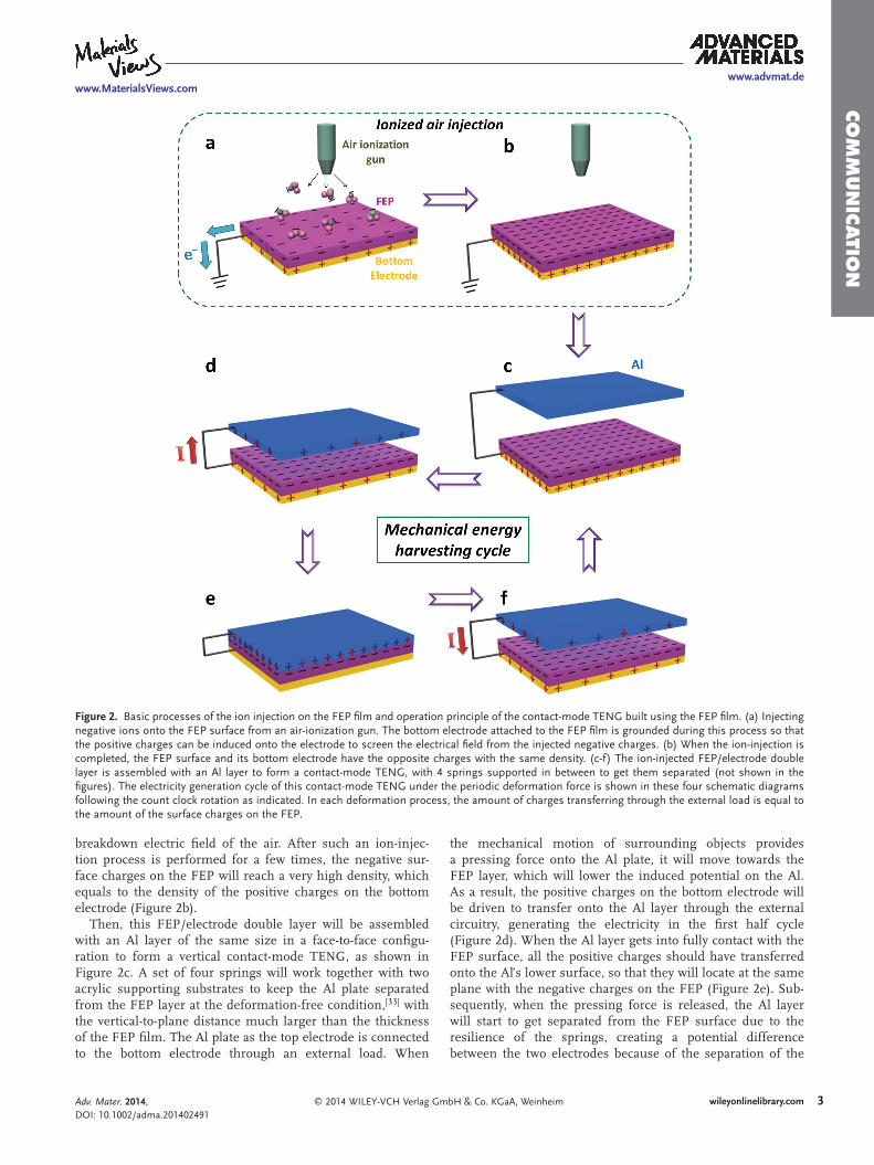
breakdown electric fi eld of the air. After such an ion-injec-tion process is performed for a few times, the negative sur-face charges on the FEP will reach a very high density, which equals to the density of the positive charges on the bottom electrode (Figure 2 b).
Then, this FEP/electrode double layer will be assembled with an Al layer of the same size in a face-to-face confi gu-ration to form a vertical contact-mode TENG, as shown in Figure 2 c. A set of four springs will work together with two acrylic supporting substrates to keep the Al plate separated from the FEP layer at the deformation-free condition, [ 33 ] with the vertical-to-plane distance much larger than the thickness of the FEP fi lm. The Al plate as the top electrode is connected to the bottom electrode through an external load. When
the mechanical motion of surrounding objects provides a pressing force onto the Al plate, it will move towards the FEP layer, which will lower the induced potential on the Al. As a result, the positive charges on the bottom electrode will be driven to transfer onto the Al layer through the external circuitry, generating the electricity in the fi rst half cycle (Figure 2 d). When the Al layer gets into fully contact with the FEP surface, all the positive charges should have transferred onto the Al’s lower surface, so that they will locate at the same plane with the negative charges on the FEP (Figure 2 e). Sub-sequently, when the pressing force is released, the Al layer will start to get separated from the FEP surface due to the resilience of the springs, creating a potential difference between the two electrodes because of the separation of the
Adv. Mater. 2014, DOI: 10.1002/adma.201402491
www.advmat.dewww.MaterialsViews.com
Figure 2. Basic processes of the ion injection on the FEP fi lm and operation principle of the contact-mode TENG built using the FEP fi lm. (a) Injecting negative ions onto the FEP surface from an air-ionization gun. The bottom electrode attached to the FEP fi lm is grounded during this process so that the positive charges can be induced onto the electrode to screen the electrical fi eld from the injected negative charges. (b) When the ion-injection is completed, the FEP surface and its bottom electrode have the opposite charges with the same density. (c-f) The ion-injected FEP/electrode double layer is assembled with an Al layer to form a contact-mode TENG, with 4 springs supported in between to get them separated (not shown in the fi gures). The electricity generation cycle of this contact-mode TENG under the periodic deformation force is shown in these four schematic diagrams following the count clock rotation as indicated. In each deformation process, the amount of charges transferring through the external load is equal to the amount of the surface charges on the FEP.

4 wileyonlinelibrary.com © 2014 WILEY-VCH Verlag GmbH & Co. KGaA, Weinheim
CO
MM
UN
ICATI
ON opposite charges. The positive charges will then transfer back
from the Al layer to the bottom electrode of FEP, producing the second current pulse in the reverse direction (Figure 2 f). When the vertical separation distance gets much larger than the thickness of the FEP fi lm, all the positive charges will return back to the bottom electrode and the TENG will revert to the state shown in Figure 2 c. Thus, in each deformation process (either pressing or releasing), the amount of charge transferred across the load equals to the amount of the nega-tive charges on the FEP surface.
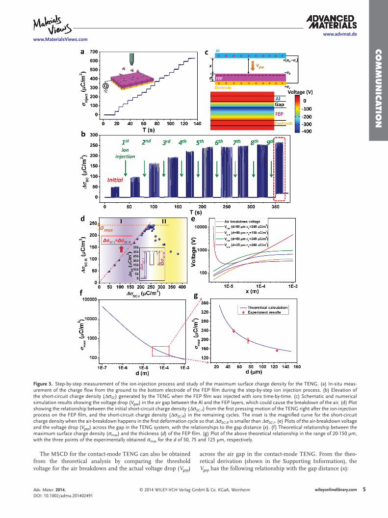
As mentioned above, through using the ion injection method, the charge density can be manually controlled, and the charge generation process is independent of the electricity generation process. Thus, this method makes it possible to systematically study the MSCD for TENGs. In the charge injection process as shown in Figure 2 a, the amount of the negative charges injected onto the FEP surface can be instan-taneously monitored by using a coulomb meter to measure the charge fl ow from the ground to the bottom electrode (inset of Figure 3 a). As shown in Figure 3 a, each time of ion injection will cause a transfer of charges with an area den-sity of ∼40 µC/m 2 from the ground to the bottom electrode, implying the charges of the same density being introduced onto the FEP surface. When the ion injection was repeated for multiple times, the negative charges injected onto the FEP surface accumulated step by step. In the consecutive 17 times of charge injection, there is no charge saturation observed and the density of the negative static charges on the FEP surface fi nally reached ∼630 µC/m 2 , as shown in Figure 3 a. This is over ten times higher than the highest charge density (53.1 µC/m 2 ) [ 34 ] that could be obtained by an electrode-free dielectric fi lm.
Such a step-by-step ion injection for the enhancement of the surface charge density has also been studied in a TENG structure. Each time after one ion injection step, the FEP/elec-trode double layer is assembled with an Al plate into a contact-mode TENG. Then the short-circuit charge density ( Δσ SC ) gen-erated by the TENG was measured, which should be equal to the surface charge density ( σ 0 ) on the FEP fi lm. In this set of experiments, the thickness of the utilized FEP fi lm is 50 µm. At fi rst, the output of the TENG was tested before the FEP fi lm was injected with negative ions, in which the static surface charges were fully generated by the triboelectrifi cation with Al. As shown in Figure 3 b, in this initial group, the TENG only produced a Δσ SC of ∼50 µC/m 2 , which stands for the triboelec-tric surface charge density on the FEP surface. Subsequently, the ion injection leaded to the elevation of the Δσ SC step by step. It should be noted that for the effective accumulation of the negative charges on the FEP surface it is very important to connect the FEP’s bottom electrode to the ground in each ion injection step. If failed to do so, the ion injection could not effectively enhance the Δσ SC (i.e. the σ 0 ) of the TENG (Figure S1). As shown in Figure 3 b, after the fi rst few times of injection, the Δσ SC approached the level around 240 µC/m 2 . Subsequently, every time of injection will only lead to a small increase on Δσ SC . After the 9 th time of injection, the charge transfer behavior suddenly became distinctively different, as marked by the red box in Figure 3 b. The fi rst pressing motion after the additional cycle of ion-injection led to a charge
transfer with a density of ∼260 µC/m 2 . Then, when the Al layer was released to get separated from the FEP layer, the reverse charge transfer only had an amount of ∼230 µC/m 2 , so that the Δσ SC curve could not return to the base line after the fi rst full deformation cycle. In the following cycles, the Δσ SC stayed at the level of 230 µC/m 2 . Since the amount of charge fl ow in each deformation process equals to the amount of the surface charges on FEP, this abrupt decrease of Δσ SC should come from the loss of the static surface charges as a result of air breakdown during the fi rst releasing process, which is triggered by a voltage drop across the air gap between the Al layer and the FEP surface during the separation pro-cess (Figure 3 c). The existence of this voltage drop can be veri-fi ed by the numerical simulation of the potential distribution in this TENG system at the short-circuit condition. As shown in the bottom image of Figure 3 c, when the gap distance is half the thickness of the FEP (set as 50 µm in the simulation model), a voltage drop ( V gap ) of ∼300 V exists across the air gap, which is proportional to the σ 0 on the FEP. So if a σ 0 leads to a V gap higher than the threshold voltage for the air breakdown at a certain gap distance, the positive ions from the air discharging corona will partially screen the negative charges on the FEP surface. This would result in the loss of the surface charges in the fi rst cycle of deformation after the ion injection.
With the help of this ion injection method, this unique charge transfer behavior in the last group of operation in Figure 3 b can serve as an indication of the air breakdown during the operation of the TENG, in which the initial short-circuit charge density ( Δσ SC-I ) from the fi rst pressing defor-mation is evidently larger than the charge density ( Δσ SC-R ) in the remaining deformation cycles thereafter, as shown in such a magnifi ed charge transfer curve in the inset of Figure 3 d. This provides an effective way to study the MSCD for a TENG structure. Through changing the times of ion injection, we introduced widely-varied surface charge densities onto the FEP layer. After each set of ion injections, the FEP fi lm was assembled into the TENG to test the charge transfer behavior, from which the Δσ SC-I and Δσ SC-R can be obtained and then plotted in the same fi gure with the Δσ SC-I value as the hori-zontal axis and the Δσ SC-R as the vertical axis. As shown in Figure 3 d, in the Region I where Δσ SC-I is within the relatively small range, the plotted points almost stay on the line of Δσ SC-I = Δσ SC-R . This is the normal charge transfer behavior we observed from the TENG in which there is no air breakdown happening. Then, when the Δσ SC-I is further increased to a range over 200 µC/m 2 , the points start to deviate downward from the above line, and the surface charge density starts to get into Region II in which the air breakdown is induced. In this region, a higher Δσ SC-I leads to a smaller Δσ SC-R . The pos-sible reason is that when the surface charge density on the FEP exceeds the maximum charge density by a larger extend, the discharging of the air will be more intensive, which could probably cause a stronger screening to the negative surface charges on the FEP. From this plot, the MSCD can be easily obtained either from the border between the two regions, or from the highest achievable value of the Δσ SC-R . Thus, the σ max for this TENG structure with the FEP thickness of 50 µm is ∼240 µC/m 2 .
Adv. Mater. 2014, DOI: 10.1002/adma.201402491
www.advmat.dewww.MaterialsViews.com
5wileyonlinelibrary.com© 2014 WILEY-VCH Verlag GmbH & Co. KGaA, Weinheim
CO
MM
UN
ICATIO
N
The MSCD for the contact-mode TENG can also be obtained from the theoretical analysis by comparing the threshold voltage for the air breakdown and the actual voltage drop ( V gap )
across the air gap in the contact-mode TENG. From the theo-retical derivation (shown in the Supporting Information), the V gap has the following relationship with the gap distance ( x ):
Adv. Mater. 2014, DOI: 10.1002/adma.201402491
www.advmat.dewww.MaterialsViews.com
Figure 3. Step-by-step measurement of the ion-injection process and study of the maximum surface charge density for the TENG. (a) In-situ meas-urement of the charge fl ow from the ground to the bottom electrode of the FEP fi lm during the step-by-step ion injection process. (b) Elevation of the short-circuit charge density ( Δσ SC ) generated by the TENG when the FEP fi lm was injected with ions time-by-time. (c) Schematic and numerical simulation results showing the voltage drop ( V gap ) in the air gap between the Al and the FEP layers, which could cause the breakdown of the air. (d) Plot showing the relationship between the initial short-circuit charge density ( Δσ SC-1 ) from the fi rst pressing motion of the TENG right after the ion-injection process on the FEP fi lm, and the short-circuit charge density ( Δσ SC-R ) in the remaining cycles. The inset is the magnifi ed curve for the short-circuit charge density when the air-breakdown happens in the fi rst deformation cycle so that Δσ SC-R is smaller than Δσ SC-I . (e) Plots of the air-breakdown voltage and the voltage drop ( V gap ) across the gap in the TENG system, with the relationships to the gap distance ( x ). (f) Theoretical relationship between the maximum surface charge density ( σ max ) and the thickness ( d ) of the FEP fi lm. (g) Plot of the above theoretical relationship in the range of 20-150 µm, with the three points of the experimentally obtained σ max for the d of 50, 75 and 125 µm, respectively.

6 wileyonlinelibrary.com © 2014 WILEY-VCH Verlag GmbH & Co. KGaA, Weinheim
CO
MM
UN
ICATI
ON
0
0
Vd x
d xgap
r
σε ε( )=
+
(1)
where d is the thickness of the FEP fi lm, ε r is the relative per-mittivity of the FEP layer, and ε 0 is the vacuum permittivity. This relationship between the V gap and the x can be plotted under different σ 0 and d , as shown in Figure 3 e (the blue, green, orange and purple curves). It can be found that both a higher σ 0 and a higher d will bring a larger V gap .
For the breakdown voltage of a gas between two plates at a small gap distance, it follows the Paschen curve—an empirical law showing the relationship of the breakdown voltage and the gap distance: [ 35,36 ]
lnV
A Px
Px Ba b
( )( )
=+−
(2)
where P is the pressure of the gas, A and B are the constants determined by the composition and the pressure of the gas. For air at standard atmospheric pressure of 101 kPa (i.e. the usual surrounding condition of a TENG), A = 2.87 × 10 5 V/(atm·m), and B = 12.6. [ 36 ] The curve for the air breakdown threshold is also plotted in Figure 3 e (the red curve). It can be found that the minimum value of the threshold voltage is reached at a cer-tain gap distance.
Thus, when x starts to increase from 0 during the releasing half cycle of the TENG, the V gap needs to remain smaller than V a-b at any x > 0 in order to avoid breakdown of air, which also means that the V gap curve is required to stay below the air breakdown curve shown in Figure 3 e. So the following relation-ship should be satisfi ed for any x > 0:
ln
00
0
A Px
Px B
d x
d x r
σε ε( )
( )( ) +
−+
>
(3)
From this, the MSCD ( σ max ) for a TENG with the dielectric thickness of d is:
ln
minmax0AP d x
d Px Brσ
ε ε(
( )( )
=+
+⎛
⎝⎜⎞
⎠⎟
(4)
From this equation, with d = 50 µm (the same as this experi-
mentally studied case), the theoretical σ max is numerically cal-culated to be 241.05 µC/m 2 , which matches very well with the above experimentally obtained value of ∼240 µC/m 2 . As shown in Figure 3 e, when d = 50 µm and σ 0 = 240 µC/m 2 , the V gap curve (blue) is in tangential contact with the air breakdown voltage curve, refl ecting the threshold condition.
Moreover, the Equation ( 4) also clearly reveals the infl uence of the TENG’s structural parameter—the thickness ( d ) of the dielectric fi lm—on the σ max . Through numerically plotting the curve of σ max vs. d according to this equation, we can fi nd that the σ max will get larger at a smaller fi lm thickness, as shown in Figure 3 f. With the d reduced from the range of tens of microns to hundreds of nanometers, the σ max will increase by 2 orders of magnitude to go beyond 10 mC/m 2 . Such a theoretical rela-tionship between the σ max and the d can be verifi ed by experi-ments. We further carried out 2 similar sets of experiments on the FEP fi lms with the thicknesses of 75 µm and 125 µm, respectively, to determine the corresponding σ max for them with
the help of the ion-injection method. The Δσ SC-I ∼ Δσ SC-R plots for these two fi lm thicknesses are shown in Figure S2, from which the σ max values can be obtained. Then the three points representing the σ max for these d values were plotted together with the theoretical σ max ∼ d curve within the range of 20–150 µm in Figure 3 g. It can be found that the experimental points have a very good overlapping with the theoretical curve. Thus, this infl uencing behavior of the fi lm thickness on the MSCD has been illustrated both theoretically and experimentally, which clearly indicates that a thinner dielectric fi lm is favorable for building a high-output TENG through the improvement of the surface charge density.
We also experimentally studied the effectiveness of this ion injection method for the improvement of the surface charge density in the other two fundamental modes of TENGs—the sliding mode [ 19,20 ] and the single-electrode mode. [ 23 ] As for the sliding mode, the Δσ SC from the 50-µm-FEP-based sliding-TENG has been improved by over one time through the injection of the negative ions (Figure S3), which refl ects the improvement on the surface charge density ( σ 0 ). However, it can be noticed that the σ max of this sliding-TENG is much smaller than that of the contact-mode TENG with the same fi lm thickness ( d ). This should result from a different distribution and strength of the electric fi eld at the separating edge in the sliding-TENG. For the single-electrode mode TENG, in which the dielectric fi lm doesn’t have an electrode layer attached at the back, the ion injection method cannot effectively improve the surface charge density, as shown in Figure S4. This is because that with the absence of the back electrode, there is no oppositely charged layer to screen the electric fi eld generated by the negative charges on the FEP, so that the air breakdown can be initiated at a large charge density. Thus, it implies that compared to the single-electrode TENGs in which the surface charge density can only stay at a low range, the contact-mode and the sliding-mode are favorable for realizing a high power output.
This ion injection method for the introduction of the sur-face charges can largely enhance the power output of the TENG for mechanical energy harvesting, through effectively increasing the surface charge density on the FEP. From the measured Δσ SC of the TENG before and after the ion injec-tions as shown in Figure 3 b, a fi ve-fold enhancement of the surface charge density (also the Δσ SC ) is achieved by this ion injection method, which should lead to a proportional increase of both the open-circuit voltage ( V OC ) and the short-circuit cur-rent density ( J SC ). As shown in Figure 4 a, before the ion injec-tion, the TENG can only produce a V OC of ∼200 V. After the ion injection from which the surface charge density was increased to the maximum value (240 µC/m 2 ), the V OC from the TENG was increased to ∼1000 V (Figure 4 b). As for the J SC before and after the ion injection both generated by gentle hand pressing (with an approximate pressing force of 20 N), it increased from ∼18 mA/m 2 to ∼78 mA/m 2 (Figure 4 c&d). If this ion-injection-enhanced TENG was triggered by a much higher pressing force that leads to a much faster deformation process, the generated J SC could reach a very large magnitude. As shown in Figure 4 e, under the pressing force of ∼300 N, the TENG generated a J SC as high as 900 mA/m 2 . It should be noted that the varied magnitudes of the J SC peaks come from the variation of the
Adv. Mater. 2014, DOI: 10.1002/adma.201402491
www.advmat.dewww.MaterialsViews.com

7wileyonlinelibrary.com© 2014 WILEY-VCH Verlag GmbH & Co. KGaA, Weinheim
CO
MM
UN
ICATIO
N
dynamic deformation rates of the TENG. Under this deforma-tion condition, the actual power output from this ion-injection-enhanced TENG was tested by connecting the TENG to a series of loads with different resistances. As shown in Figure 4 f, the current density through the load gradually decreases with the increase of the resistance, while the voltage follows a reverse
trend. The power output density of this TENG reached the maximum value of ∼315 W/m 2 at the resistance of 300 MΩ. Therefore, the ion-injection is a very effective method for the improvement of TENGs’ power output. Considering that the MSCD becomes larger when the fi lm thickness gets smaller, the power output of the TENG can possibly be enhanced to a
Adv. Mater. 2014, DOI: 10.1002/adma.201402491
www.advmat.dewww.MaterialsViews.com
Figure 4. Enhancement of the TENG’s output performance by the ion injection method. (a-b) Open-circuitvoltages of the TENG: (a) before any ion injection process, in which the surface charges are only generated by the triboelectrifi cation; (b) after the ion-injection process that increased the surface charge density on the FEP to the maximum value. (c-d) Short-circuit current densities of the TENG under the gentle pressing of hand with the force of ∼20 N: (c) before any ion injection process; (d) after the ion-injection process that increased the surface charge density on the FEP to the maximum value. (e) Short-circuit current density of the TENG after the ion injection, under the deformation force of ∼300 N. (f) With the above TENG after the ion-injection connected to the loads with different resistances, the current density and the voltage on the loads. (g) Power density obtained by the loads with difference resistances.

8 wileyonlinelibrary.com © 2014 WILEY-VCH Verlag GmbH & Co. KGaA, Weinheim
CO
MM
UN
ICATI
ON
much higher level by the ion-injection method if a thinner FEP fi lm is used.
When the TENG is constructed by an electret fi lm (e.g., the FEP in this demonstration), the surface charges brought by the ion-injection method can be preserved for as long as years, so that the TENG can deliver an elevated output for a long term after its dielectric surface gets pre-charged. In order to study the stability of the surface charge on the FEP, we reg-ularly measured the Δσ SC from the TENG constructed using this FEP fi lm in a time range of 160 days. From the results in Figure 5 a, the Δσ SC only decayed from the initial value of 240 µC/m 2 that was measured right after the ion injection, to ∼200 µC/m 2 after 80 days, and then almost got stabilized at this value. Thus, there is only ∼16.6% loss of the surface charges, and the remained Δσ SC after 160 days is still 3 times higher than the Δσ SC generated by the TENG without the ion injection process. Moreover, even when the ion-injection-charged FEP surface is kept in the intimate contact with the Al fi lm for an extended period of time, the negative charges can still stably exist, with the experimental data shown in Figure S5. Thus, under the continuous operation during which the FEP surface and the Al get into contact from time to time, the largely elevated output of this TENG should still have a good stability. As shown in Figure 5 b, when the con-tact-mode TENG was periodically triggered by the external pressing force, the generated Δσ SC only has a little decay in the continuous operation of ∼400 000 cycles. Therefore, both of the above two groups of measurements clearly show that the ion injection method is an effective and practical method for building the TENG that can deliver a largely-enhanced output for a suffi ciently long time.
Because the air-ionization gun can generate and inject both positive and negative ions in a selective manner, this ion injec-tion method we demonstrated in this work could possibly get the triboelectrically-negative FEP fi lm positively charged. As shown in Figure S6, 10 repeated times of positive ion injec-tion converted the negatively-charged FEP surface with a den-sity of −240 µC/m 2 to the state of carrying +200 µC/m 2 posi-tive charges. However, it has been observed that the stability of the positive charges on the FEP surface is much worse than the negative charges (from the comparison of Figure 5 a and Figure S8). Thus, the electret material can only stably preserve the charges with the same polarity of the material itself. More-over, the ion injection method can also signifi cantly enhance the surface charge density on non-dielectric materials (e.g. Kapton) and thus improve the power output of the constructed TENGs, as shown in Figure S6. It can be noticed that the σ max of the Kapton fi lm with the same thickness (50 µm) is a bit higher than the σ max of the FEP layer. This is because Kapton’s relative permittivity ( ε r = 3.4) is larger than that ( ε r = 2.1) of FEP. As expected, the injected charges on the non-electret Kapton fi lm showed a much faster decay than the charges on the electret fi lm (Figure S9).
The relationship between the TENGs’ maximum surface charge density and the thickness of the dielectric fi lm unraveled in this paper clearly shows the possibility of improving the tri-boelectric charge density in TENGs by as much as 2 orders of magnitude! This could be achieved through the research efforts in the following directions. First, in-depth studies on the fun-damental mechanism of the contact electrifi cation process using advanced technologies and tools (such as atomic force microscopy) [ 5,6,37,38 ] can help us to gain better insights about the driving force for the charge transfer during the contact elec-trifi cation. Second, the development of chemical approaches to modify the material and/or functionalize the surface will realize the increase of the driving force for the triboelectrifi ca-tion: either by creating two triboelectric surfaces densely cov-ered with the highly polarized functional groups respectively (e.g., -F, -Cl as the negative functional groups and -NH 2 , amide, pyridine as the positive groups), [ 39 ] or even by synthesizing new functional groups with higher polarities. Moreover, according to deepened understanding of the contact-electrifi cation, intro-ducing the optimized nano-/micro-structures on the surface could also help to increase the obtained surface charge density. Thus, the discoveries in this paper open up a huge research opportunity in the fi eld of triboelectric nanogenerators for the chemists and material scientists.
In summary, the ion injection method for the introduction of surface charges demonstrated in this paper has helped us to make three hallmarked progresses along the research track of the improvement to the triboelectric nanogenerators’ power output. Firstly, this method provides a simple but effective approach for the enhancement of the TENG’s output, through which a 25-fold enhancement and a maximum power den-sity of ∼315 W/m 2 have been achieved in the contact-mode. By using an electret material, the enhanced power output can stably exist at least for months. Secondly, with the help of this method, the existence of the maximum surface charge density for the TENGs due the limitation of the air breakdown was observed and confi rmed for the fi rst time. Thirdly, and the
Adv. Mater. 2014, DOI: 10.1002/adma.201402491
www.advmat.dewww.MaterialsViews.com
Figure 5. Stability of the electret-based TENG with the dielectric surface injected with ions. (a) Stability of the surface charges on the FEP layer obtained from the ion injection process, which was tested through meas-uring the Δσ SC from the TENG. (b) Stability of the TENG when it was continuously operating for ∼400,000 cycles.
9wileyonlinelibrary.com© 2014 WILEY-VCH Verlag GmbH & Co. KGaA, Weinheim
CO
MM
UN
ICATIO
N
most importantly, we unraveled the direct relationship between the maximum surface charge density and the thickness of the dielectric fi lm in the TENG, both experimentally and theoreti-cally, which not only tells us that thinner dielectric fi lms as the triboelectric layers are favorable for achieving higher sur-face charge density, but also clearly shows the huge room for future improvement of the TENGs’ power output. By reducing the fi lm thickness to the range of hundreds nanometers, the surface charge density could be 2 orders of magnitudes higher than the current level, which indicates a 4-order of improve-ment on the TENGs’ output power! This will create a huge drive for the material and chemistry research for improving the sur-face charge density obtained from triboelectrifi cation processes. Through these studies, not only the TENG-based mechanical energy harvesting will be promoted to technologies and prod-ucts that reach people’s daily life, but also the development of the surface chemistry and the fundamental understandings of contact electrifi cation will be largely propelled.
Supporting Information Supporting Information is available from the Wiley Online Library or from the author.
Acknowledgements Research was supported by Basic Energy Sciences DOE, MURI from Airforce, the Hightower Chair foundation, and the “thousands talents” program for pioneer researcher and his innovation team.
Received: June 4, 2014 Revised: June 25, 2014
Published online:
[1] R. G. Horn , D. T. Smith , Science 1992 , 256 , 362 . [2] R. G. Horn , D. T. Smith , A. Grabbe , Nature 1993 , 366 , 442 . [3] J. Lowell , A. C. Roseinnes , Adv. Phys. 1980 , 29 , 947 . [4] D. J. Lacks , R. M. Sankaran , J. Phys. D Appl. Phys. 2011 , 44 , 453001 . [5] H. T. Baytekin , B. Baytekin , T. M. Hermans , B. Kowalczyk ,
B. A. Grzybowski , Science 2013 , 341 , 1368 . [6] H. T. Baytekin , A. Z. Patashinski , M. Branicki , B. Baytekin , S. Soh ,
B. A. Grzybowski , Science 2011 , 333 , 308 . [7] D. K. Davies , J. Phys. D Appl. Phys. 1969 , 2 , 1533 .
[8] J. Henniker , Nature 1962 , 196 , 474 . [9] W. D. Greason , IEEE T. Ind. Appl. 1987 , 23 , 205 .
[10] N. Gibson , J. Electrostat. 1997 , 40-1 , 21 . [11] M. Angelopoulos , IBM J. Res. Dev. 2001 , 45 , 57 . [12] D. M. Pai , B. E. Springett , Rev. Mod. Phys. 1993 , 65 , 163 . [13] L. B. Schein , J. Imaging Sci. Techn. 1996 , 40 , R6 . [14] B. A. Kwetkus , Particul. Sci. Technol. 1998 , 16 , 55 . [15] C. Y. Liu , A. J. Bard , Nat. Mater. 2008 , 7 , 505 . [16] B. Baytekin , H. T. Baytekin , B. A. Grzybowski , J. Am. Chem. Soc.
2012 , 134 , 7223 . [17] F. R. Fan , Z. Q. Tian , Z. L. Wang , Nano Energy 2012 , 1 , 328 . [18] S. H. Wang , L. Lin , Z. L. Wang , Nano Lett. 2012 , 12 , 6339 . [19] S. H. Wang , L. Lin , Y. N. Xie , Q. S. Jing , S. M. Niu , Z. L. Wang , Nano
Lett. 2013 , 13 , 2226 . [20] L. Lin , S. H. Wang , Y. N. Xie , Q. S. Jing , S. M. Niu , Y. F. Hu ,
Z. L. Wang , Nano Lett. 2013 , 13 , 2916 . [21] Z. H. Lin , G. Cheng , L. Lin , S. Lee , Z. L. Wang , Angew. Chem. Int.
Edit. 2013 , 52 , 12545 . [22] S. H. Wang , Z. H. Lin , S. M. Niu , L. Lin , Y. N. Xie , K. C. Pradel ,
Z. L. Wang , ACS Nano 2013 , 7 , 11263 . [23] Y. Yang , H. L. Zhang , J. Chen , Q. S. Jing , Y. S. Zhou , X. N. Wen ,
Z. L. Wang , ACS Nano 2013 , 7 , 7342 . [24] X. S. Zhang , M. D. Han , R. X. Wang , F. Y. Zhu , Z. H. Li , W. Wang ,
H. X. Zhang , Nano Lett. 2013 , 13 , 1168 . [25] S. H. Wang , Y. N. Xie , S. M. Niu , L. Lin , Z. L. Wang , Adv. Mater.
2014 , 26 , 2818 . [26] S. M. Niu , Y. Liu , S. H. Wang , L. Lin , Y. S. Zhou , Y. F. Hu , Z. L. Wang ,
Adv. Mater. 2013 , 25 , 6184 . [27] S. M. Niu , S. H. Wang , L. Lin , Y. Liu , Y. S. Zhou , Y. F. Hu , Z. L. Wang ,
Energ Environ. Sci. 2013 , 6 , 3576 . [28] M. Eguchi , Philos Mag 1925 , 49 , 178 . [29] G. M. Sessler , J. Hillenbrand , Appl. Phys. Lett. 1999 , 75 , 3405 . [30] M. J. Waltman , P. Dwivedi , H. H. Hill , W. C. Blanchard , R. G. Ewing ,
Talanta 2008 , 77 , 249 . [31] H. O. Jacobs , G. M. Whitesides , Science 2001 , 291 , 1763 . [32] Y. Sakane , Y. Suzuki , N. Kasagi , J. Micromech. Microeng. 2008 , 18 ,
104011 . [33] G. Zhu , Z.-H. Lin , Q. S. Jing , P. Bai , C. F. Pan , Y. Yang , Y. S. Zhou ,
Z. L. Wang , Nano Lett. 2013 , 13 , 847 . [34] J. A. Cross , Electrostatics : principles, problems and applications ,
Hilger , Bristol , 1987 . [35] M. A. Lieberman , A. J. Lichtenberg , Principles of plasma discharges
and materials processing , 2nd ed. , Wiley-Interscience , Hoboken, N.J ., 2005 .
[36] K. T. A. L. Burm , Contrib. Plasm. Phys. 2007 , 47 , 177 . [37] Y. S. Zhou , Y. Liu , G. Zhu , Z. H. Lin , C. F. Pan , Q. S. Jing ,
Z. L. Wang , Nano Lett. 2013 , 13 , 2771 . [38] Y. S. Zhou , S. H. Wang , Y. Yang , G. Zhu , Z.-H. Lin , Y. Liu , Z. L. Wang ,
Nano Lett. 2014 , 14 , 1567 . [39] A. F. Diaz , R. M. Felix-Navarro , J. Electrostat. 2004 , 62 , 277 .
Adv. Mater. 2014, DOI: 10.1002/adma.201402491
www.advmat.dewww.MaterialsViews.com