maximum height to width ratio of freestanding structures built using ultrasonic...
TRANSCRIPT

Maximum Height to Width Ratio of Freestanding Structures Built using Ultrasonic Consolidation
C.J. Robinson, C. Zhang, G.D. Janaki Ram, E.J. Siggard, B. Stucker, and L. Li Department of Mechanical and Aerospace Engineering, Utah State University
Logan, UT 84322-4130, USA
Abstract Ultrasonic consolidation (UC) is a process whereby metal foils can be metallurgically bonded at or near room temperature. The UC process works by inducing high-speed differential motion (~20kHz) between a newly deposited layer and a substrate (which consists of a base plate and any previously deposited layers of material). This differential motion causes plastic deformation at the interface, which breaks up surface oxides and deforms surface asperities, bringing clean metal surfaces into intimate contact, where bonding occurs. If the substrate is not stiff enough to resist deflection during ultrasonic excitation of newly deposited layers, then it deflects along with the newly deposited layer, resulting in no differential motion and lack of bonding. Geometric issues which control substrate stiffness and deflection were investigated at Utah State University by building a number of free-standing rib structures with varying dimensions and orientations. Each structure was built to a height where lack of bonding between the previously deposited layers and the newly deposited layer caused the building process to fail, a height to width ratio (H/W) of approximately 1:1. The parts were then cut, polished, and viewed under a microscope. An ANSYS model was created to investigate analytically the cause of this failure. It appears build failure is due to excessive deflection of the ribs around a 1:1 H/W, resulting in insufficient differential motion and deformation to achieve bonding. Preliminary results show, when the H/W reaches 1:1, the von Mises stress is found to be tensile along portions of the bonding interface, which eliminates the compressive frictional forces necessary for plastic deformation and formation of a metallurgical bond. These tensile stresses are shown to be concentrated at regions near the edges of the newly deposited foil layer.
1. Introduction Ultrasonic Consolidation (UC) is a novel additive manufacturing process developed by Solidica Inc., USA, utilizing the principles of ultrasonic welding [1]. The process builds up the rough part shape by ultrasonically welding or consolidating thin metal foils (typically 150 mthick). This ultrasonic addition is combined with 3-axis CNC milling to produce geometric details. The Solidica Form-ation UC machine, commercially introduced by Solidica in 2000, is an integrated machine tool which incorporates an ultrasonic welding head, a foil feeding mechanism, a 3-axis milling machine, and software to automatically generate tool paths for material deposition and machining. Part fabrication takes place on a firmly bolted base plate (typically of the same material as the foil being deposited) on the top of a heat plate. The heat plate maintains the substrate at a set temperature allowing the deposition process to be carried out at temperatures ranging from ambient to 350 F.
Fig.1 illustrates the basic UC additive manufacturing process. In this process a rotating ultrasonic sonotrode travels along the length of a thin metal foil placed over the substrate. The thin foil is held closely in contact with the substrate by applying a normal force via the rotating sonotrode. The sonotrode oscillates transversely to the direction of welding at a frequency of 20
Reviewed, accepted September 14, 2006
502

kHz and at a user-set oscillation amplitude, while traveling over the metal foil. The combination of normal and oscillating shear forces results in generation of dynamic interfacial stresses at the interface between the two mating surfaces [1-3]. The stresses produce elastic-plastic deformation of surface asperities, which breaks up the oxide film, producing relatively clean metal surfaces under intimate contact, establishing a metallurgical bond. Oxide films, broken up during the process, are displaced in the vicinity of the interface or along the weld zone. Local temperatures at the interface and the surrounding affected region (about 20 m) can reach up to 50% of the melting point of the material being deposited [3]. After depositing a strip of foil, another foil is deposited adjacent to it. This process repeats until a complete layer is placed. After placing a layer, a computer controlled milling head shapes the layer to its slice contour. This milling can occur after each layer or, for certain geometries, after several layers have been deposited. Once the layer is shaped to its contour, the chips are blown away using compressed air and foil deposition starts for the next layer.
Fig.1. Schematic of the ultrasonic consolidation process.
A closer examination of the UC process indicates that the process works, on a fundamental level, by inducing high-speed differential motion between the layer being deposited and the substrate (which consists initially of a base plate and subsequently becomes the previously deposited layers of material). This differential motion is extremely important in producing interfacial stresses of adequate magnitude to cause oxide layer removal and plastic deformation at the interface, which are essential for bonding to occur. If the substrate is not stiff enough to resist deflection during ultrasonic excitation of newly deposited layers, then it deflects along with the newly deposited layer, resulting in no differential motion. Under these conditions, the applied ultrasonic energy fails to generate high-enough stresses at the interface leading to lack of bonding. Since the substrate stiffness, for a given material, is dependent on its geometrical shape and dimensions, the UC process can be expected to be restricted to shapes and dimensions that would provide a stiff enough substrate for subsequent layer depositions.
503
While the above sounds quite plausible and is certainly a cause for concern, no published studies have been directed to examine the effect of substrate stiffness on bond formation during ultrasonic consolidation. A detailed understanding of this aspect is extremely important for successfully building parts, especially thin wall structures. Further, little is known about the effect of deposition orientation, which can provide a practical solution to the problem of substrate deflection, as the way ultrasonic oscillations are oriented with respect to substrate dimensions can significantly alter its resistance to deflection. In view of the above, the current work has been under taken to examine the role of substrate stiffness (in this case the height to width ratio) and deposition orientation on bond formation during ultrasonic consolidation of Al alloy 3003. An attempt has also been made to gain greater insights into the subject through ANSYS modeling.
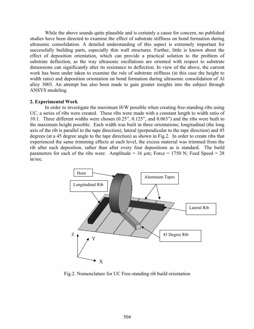
2. Experimental Work In order to investigate the maximum H/W possible when creating free-standing ribs using UC, a series of ribs were created. These ribs were made with a constant length to width ratio of 10:1. Three different widths were chosen (0.25”, 0.125”, and 0.063”) and the ribs were built to the maximum height possible. Each width was built in three orientations; longitudinal (the long axis of the rib is parallel to the tape direction), lateral (perpendicular to the tape direction) and 45 degrees (at a 45 degree angle to the tape direction) as shown in Fig.2. In order to create ribs that experienced the same trimming effects at each level, the excess material was trimmed from the rib after each deposition, rather than after every four depositions as is standard. The build parameters for each of the ribs were: Amplitude = 16 μm; Force = 1750 N; Feed Speed = 28 in/sec.
Fig.2. Nomenclature for UC Free-standing rib build orientation
ZY
X
Aluminum Tapes
Lateral Rib
45 Degree Rib
Longitudinal Rib
Horn
504

3. Experimental Results As each rib was built, they were observed carefully to note the height when ribs failed to build properly. The build process was halted when the last deposited tape did not adhere to the previously deposited tape or when the last deposited tape “peeled up” during the trimming operation. The ribs were then cross-sectioned and observed under the microscope to ascertain the quality of the welds within the ribs. The results of each rib orientation follow.
3.1 Longitudinal Ribs When building a rib along the direction of the tape the horn is vibrating perpendicular to the tape direction (across the width of the rib). This is the direction where the rib exhibits the least resistance to vibration, which should lead to the worst linear weld density, a measure of weld quality in UC as height increases [4]. Linear weld density is also discussed in a separate paper in these proceedings [5]. However, this direction of build allows the entire rib to be entirely created from a single tape, so issues that arise from having tapes laid next to each other, such as seams and the fact that they act as discontinuities during the trimming operation, are eliminated.
The appearance of the ribs built longitudinally was very good, as there were no seams due to adjacent placement of tapes. There was, however, noticeable lack of bonding along the edges of some ribs, as can be seen in Fig.3. A summary of the results, including the height of the ribs and the H/W, are shown in Table 1 and a graphical representation of height to width is shown in Fig.4. In this build orientation the average H/W was 0.943. Two additional ribs were built in this direction of widths 0.50” and 0.93”. The H/W of these ribs was 0.89 and 0.98 respectively. For each rib built in this orientation the mode of failure was detachment during the machining process. This would imply that the edges of each tape were not well bonded and there was excessive tape vibration during machining, which resulted in delamination due to insufficient bonding. When the ribs were polished and viewed under a microscope it appears that the weld density was very good in the center of the ribs, but the edges showed significant defects, Fig.5 shows these edge defects in the 0.93” rib. As the part height increased, there was little change in weld density, but the ribs with fewer defects were able to build to a greater H/W.
Fig.3. Specimen with poor bonding at the edge (0.125” width).
The edge of the rib is dark colored indicating a lack of bonding.
The center of the rib is light colored, which indicates a well bonded area.
505

Table 1. Results of longitudinal rib experiments. Width
(in) Orientation Number of layers
Height(in) Ratio
0.25 long 40 0.244 0.976 0.125 long 16 0.0976 0.7808 0.0625 long 11 0.0671 1.0736
Average Ratio = 0.943
Fig.4. Plot of height versus width of freestanding longitudinal ribs.
(a) (b) (c) Fig.5. Microstructures of 0.93” freestanding longitudinal rib: (a) Left edge, (b) Center, and (c)
Right edge. Images are not continuous, but show that the center has a much higher weld density than the edges.
Longitudinal RibsBuilt at Utah State UniversityOctober and November 2005
0
0.05
0.1
0.15
0.2
0.25
0.3
0 0.05 0.1 0.15 0.2 0.25 0.3
Width of the Rib (in)
Heig
ht o
f the
Rib
(in)
506

Lateral RibsBuilt at Utah State UniversityOctober and November 2005
0
0.02
0.04
0.06
0.08
0.1
0.12
0.14
0.16
0.18
0.2
0 0.05 0.1 0.15 0.2 0.25 0.3
Width of the Rib (in)
Heig
ht o
f the
Rib
(in)
3.2 Lateral Ribs When building a rib across the tape direction, the vibration is along the long axis of the rib, which is the stiffest direction. One difficulty in building across the tape direction is that there is such a small bonded area for each tape, particularly the thinnest ribs, that it becomes easy to peel the tapes off even with a weld density that would maintain integrity in one of the other orientations.
Visibly the weld density did not appear as consistent as with the longitudinal ribs. The results, including the height of the ribs and the H/W, are shown in Table 2 and a graphical representation of height to width is shown in Fig.6. The average H/W in this orientation was 0.943, which is coincidently the exact same as the longitudinal ribs. It is worth noting that the H/W varied greatly between specimens in the lateral direction. The mode of failure for each of the ribs built across the tape lay direction was a lack of bonding during deposition. Fig.7 shows the three ribs built across the tape direction. When viewed under a microscope at least some of these ribs show trends that would imply that as the build height increased the weld density decreased gradually until delamination occurred, this can be seen by observation of the 0.125” lateral rib, Fig.8.
Table 2. Results of lateral ribs experiments.
Width(in) Orientation Number of
layersHeight
(in) Ratio
0.25 across 30 0.183 0.732 0.125 across 17 0.1037 0.8296 0.0625 across 13 0.0793 1.2688
Average Ratio = 0.943
Fig.6. Plot of height versus width of freestanding lateral ribs.
507

(a) (b)
(c)
Fig.7. Freestanding ribs built in the lateral direction: (a) 1/4”, (b) 1/8”, and (c) 1/16”.
(a) (b) (c)
Fig.8. Images of the 0.125” lateral free-standing rib where, from top (a), to middle (b), to bottom (c), it can be seen that the weld density decreases as height increases.
3.3 45º Ribs For ribs built at a 45º orientation, the ribs are built along the direction of maximum shear, and there is a better tradeoff between resistance to vibration and area for each weld. One concern with this build is that it creates a point at the edge of each tape seam where there is almost no force applied during consolidation (since UC force is lowered proportional to deposit area). This sharp point also acts as a discontinuity during machining, which can cause the corners of each tape to peel. If a lower layer does not bond well, then subsequent layers do not bond well, as can be seen in Fig.9.
Visibly the weld density seems to be very good in the ribs built in this orientation, other than the issue with peeling along the corners of each tape. The results including the height of the ribs and the H/W are shown in Table 3 and a graphical representation of height to width is shown
508

in Fig.10. The average H/W in this orientation was 1.017:1, which is significantly better than either of the other two orientations. The mode of failure was not consistent for the ribs built in this orientation, some failed due to machining and others because of a lack of deposition bonding strength. Fig.11 shows three ribs built at the 45 degree orientation. When viewed under a microscope these ribs show very good weld density even at the top of the ribs and along the edges, Fig.12. The 0.125” rib is the only one that showed significant defects, Fig.13, and the H/W of that rib was much lower than the other ribs built at 45 degrees. However, in some ribs built in this orientation it is possible to see where two tapes were not aligned perfectly next to each other, leaving a gap between tapes that are side by side, but this did not seem to cause adverse effects above that point in the build, as seen in Fig.14.
Fig.9. 45º rib before excess tape has been trimmed. The unbonded areas (shiny metallic) are also noticeable inside the rib (dull, white). Shiny areas inside the rib show the areas where peeling
occurred due to the machining operation.
Table 3. Results of 45º rib experiments. Width
(in) Orientation Number of layers
Height(in) Ratio
0.25 45 degree 41 0.2501 1.0004 0.125 45 degree 16 0.0976 0.7808 0.0625 45 degree 13 0.0793 1.2688
Average Ratio = 1.017
Unwelded areas
509

45º ribs Built at Utah State UniversityOctober and November 2005
0
0.05
0.1
0.15
0.2
0.25
0.3
0 0.05 0.1 0.15 0.2 0.25 0.3
Width of the Rib (in)
Hei
ght o
f the
Rib
(in)
Fig.10. Plot of width versus height of freestanding 45º ribs.
(a) (b)
(c)
Fig.11. Freestanding 45º ribs (a) 1/4”, (b) 1/8”, and (c) 1/16”.
510

(a) (b) (c)
Fig.12.Microscopic images of 45º rib structure weld density: (left) 0.063” rib top center, (center) 0.50” rib top center, and (right) 0.50” rib top left side.
(a) (b)
Fig.13. Microstructures of 0.125” free-standing ribs structure: (a) Bottom of rib, (b) Top of rib.
Fig.14. Free-standing ribs built at a 45 orientation. Exposed gaps between adjacent strips of tape.
511

Height to Width Ratios for Freestanding Ribs
00.20.40.60.8
11.21.4
1 2 3(1) Longitudinal (2) Lateral (3)45 Degree Rotation
Hei
ght t
o W
idth
Rat
io
1/4" Freestanding Ribs1/8" Freestanding Ribs1/16" Freestanding Ribs
4. Experimental Discussion The results show that under ideal conditions a H/W of 1:1 is achievable using UC. The orientation that produced the highest ratio and best weld density was the 45º orientation.However, on all 45º builds there was a significant portion of the edge that was not welded properly due to the tape peeling at adjacent sharp edge tape boundaries. Overall the 1/16” ribs built to the highest H/W value, as shown in Fig.15.
For build orientations that require laying of adjacent tapes, the seams presented major problems. These seams act as discontinuities during the milling/trimming operation, resulting in a peeling up of the tape at that location and a lack of bond in the area. As the build progresses, these areas of lack of bonding grow and sometimes result in build failure. This was particularly noticeable for the wider ribs, which needed a much larger number of layers to achieve the desired H/W. It is conceivable that a better milling feed and speed rate would result in less damage during trimming with parts with seams, which might eliminate this issue. In addition, it is possible that by trimming every fourth layer, as is customary during part building of large structures, that this problem would be reduced. However, at this point the presence of seams in free-standing ribs remains a major issue.
The 0.063” ribs achieved the highest overall H/W, which is likely due to the fact that the ribs were all built within a single tape width and that the total number of layers needed was small and thus reduced the likelihood of random trimming operation problems. Since the 0.125” ribs could not be entirely fabricated using one tape width and the surface that is bonded is small, the ribs failed premature as compared to the other ribs.
Through microscopic observation it appears that the longitudinal ribs have a very high weld density in the center, but have defects along the edges. The lateral ribs have a more consistent density across the ribs. The 45º degree ribs have near 100% weld density throughout the part, but they still fail at a H/W of about 1:1.
Fig.15. A comparison of H/W for freestanding ribs.
512

5. Modeling
Failure in freestanding ribs at a 1:1 ratio was investigated analytically using an ANSYS model. The detailed model setup and analysis process are reported in another paper in this conference [6]. The vibrational behavior of a cantilevered rib and frictional behavior of the bond interface were simulated with a 2-D dynamic FEM model. Fig. 16 shows the shear strain distributions at the 1500th vibration cycle in builds with various H/W. The shear strain measures the degree of elastic/plastic deformation, which measures the potential for bond formation. For build H/W less than 1:1, greater levels of shear strain exist near the bond interface. In addition, significant shear strain exists inside the builds. Such internal shear strain appears to be distributed in horizontal bands, apparently due to the interference of the traveling vibration waves. For build H/W greater than 1:1, the shear strain has a much lower level at the bond interface. At these build heights, the internal shear strain bands are no longer seen. This may be due in part to damping properties of aluminum which become important at H/W greater than 1:1.
Fig.16. Distribution of shear strain for the 1500th ultrasonic vibration cycle for different H/W, (a) H/W=0.25, (b) H/W=0.5, (c) H/W=0.75, (d) H/W=1.0, (e) H/W=1.5, and (f) H/W=2.0.
Since bond formation is directly driven by the friction at the interface, the effect of H/W on friction stress was also analyzed. In Fig. 17, it can be clearly seen that as the H/W increases, the peak friction stress decreases. For the H/W of 1:1, the peak friction stress is less than 1500 psi, while a minimum of 2000 psi friction stress is seen for H/W less than 1:1. Apparently, as the build height increases to H/W of 1:1, the frictional driving force for bonding has decreased to below a critical level.
513

Fig.17. Contact friction stress along the bonding interface as a function of build H/W.
6. Recommendations To be able to obtain greater H/W, there are a number of suggestions based on this study.
Free-standing, unsupported ribs should be avoided, if at all possible. Instead, patterns of ribs (such as a honeycomb pattern or intersecting ribs sections) or support material should be used. Using a honeycomb pattern, H/W exceeding 100:1 should be possible [7]. Milling across seams in ribs presents a number of issues. Seams should be avoided when possible and more optimized milling parameters may help significantly. Ribs placed longitudinally will have the least resistance to vibration. When creating patterns of ribs, avoid designing members in the longitudinal direction. Tape laying patterns should be designed in such a way to maximize bonded area of the tapes on a rib.The H/W of 1:1 as the limit for the highest ribs seems to be associated with the elastic and damping properties of the aluminum material. With other building materials, this limit may increase or decrease.
514

7. Future Work Although this study lends significantly to an understanding of free-standing ribs built using UC, a number of improvements to this study could be made.
Optimized milling parameters should be studied to help alleviate the problem of tape peeling at seams. Microscopy of cross-sections at 0º, 45º, and 90º orientations should be observed for all tapes. This will provide an accurate comparison between the weld densities achievable in the different rib orientations, which is not possible using only microscopy on slices perpendicular to the long-axis of the rib. A more careful study of patterns of ribs and supporting materials for ribs should be performed. An investigation of the effect of changing UC parameters, particularly the amplitude of vibration, is merited. The validity of a 1:1 ratio for other materials should be investigated.
8. Conclusions Freestanding ribs were built longitudinally, laterally and at a 45º degree orientation with respect to the tape direction of a UC machine. Each orientation presented a number of challenges for building free-standing ribs. The main parameters which seem to affect the ability to create free-standing ribs with a high aspect ratio are stiffness with respect to the sonotrode vibration direction, bonding area for tapes, the presence of seams in ribs, and the tape trimming operation. Careful control of these make possible ribs with a maximum H/W of approximately 1:1. The existence of this maximum height is associated with the vibrational and frictional behavior of the aluminum material under the given process conditions. When the H/W is greater than 1:1, both the shear strain and frictional stress at the bond interface are believed to have decreased to levels below the critical values for bond formation.
Acknowledgements Support for this project was provided by the National Science Foundation (DMI 0522908), by an NSF STTR grant through MicroSat Systems, Inc. (OII 0512641) and by the State of Utah Centers of Excellence Program (Center for Advanced Satellite Manufacturing).
References 1. White, D.R. (2003). “Ultrasonic consolidation of aluminium tooling.” Advanced Materials
and Processes (v161), pp64-65.2. Daniels, H.P.C. (1965). “Ultrasonic welding.” Ultrasonics, pp190-196. 3. O’Brien, R.L. “Welding Processes.” in Welding Handbook (v2, 8th ed.), American Welding
Society, Miami, 1991. 4. Kong, C.Y.; Soar, R.C.; and Dickens, P.M. (2004). “Optimum process parameters for
ultrasonic consolidation of 3003 aluminium.” Journal of Materials Processing Technology(v146), pp181-187.
5. G.D. Janaki Ram, Y. Yang, J. George, C. Robinson and B.E. Stucker, Improving linear weld density in ultrasonically consolidated parts, Solid Freeform Fabrication Symposium,Austin, TX, 2006.
515

6. Chunbo Zhang, Leijun Li, 2006, “A Study of Static and Dynamic Mechanical Behavior of Substrate in Ultrasonic Consolidation,” Solid Freeform Fabrication Symposium, Austin, TX, 2006.
7. J. Clements and J. George 2006, “Rapid Manufacturing of Satellite Structures and Heat Pipes using Ultrasonic Consolidation”, American Institute of Aeronautics and Astronautics 2006, Proceedings of the 20th Annual Conference on Small Satellites August 14-17, 2006.
516