maximizing productivity for twin-screw …...maximizing productivity for twin-screw compounding adam...
TRANSCRIPT
Maximizing Productivity for
Twin-Screw Compounding
Adam Dreiblatt
Director, Process Technology
Presentation outline
� Increase capacity
- Optimized screw designs for feeding limitation
- High torque and high speed compounding
� Improve quality
- How extruder wear affects compound quality- How extruder wear affects compound quality
� Maximize profitability
- Highest production rate
- Achieve and maintain compound quality
- Best machine reliability

For most compounding applications, the maximum
capacity for twin-screw compounding extruders
will be limited by
� how much power they can apply or
� how much material the extruder can feed
Production rate limitations
� how much material the extruder can feed
We cannot change the volume of the extruder, but
we can change the efficiency for conveying
material within the extruder and increase the
production rate with optimized screw designs.
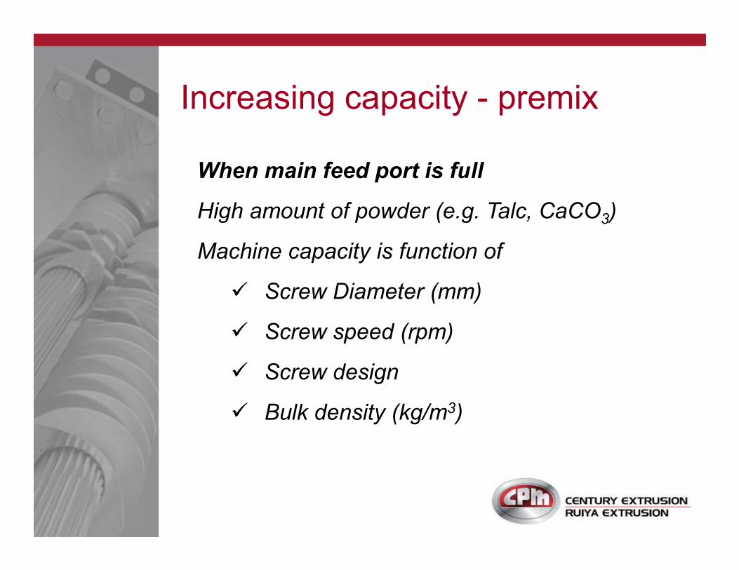
When main feed port is full
High amount of powder (e.g. Talc, CaCO3)
Machine capacity is function of
� Screw Diameter (mm)
Increasing capacity - premix
� Screw Diameter (mm)
� Screw speed (rpm)
� Screw design
� Bulk density (kg/m3)
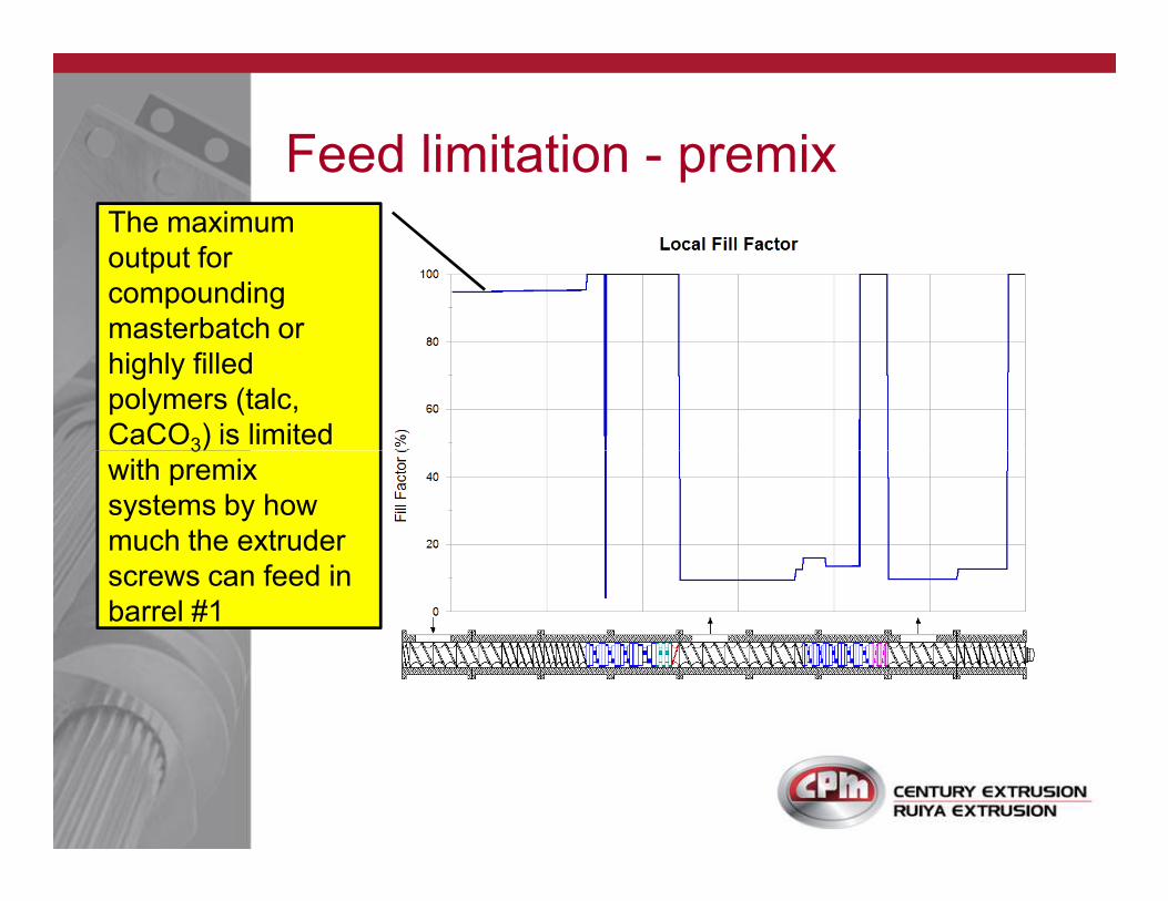
Feed limitation - premix The maximum
output for
compounding
masterbatch or
highly filled
polymers (talc,
CaCO3) is limited 3
with premix
systems by how
much the extruder
screws can feed in
barrel #1
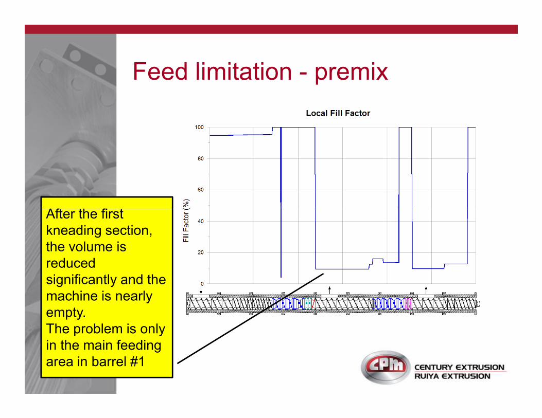
Feed limitation - premix
After the first After the first
kneading section,
the volume is
reduced
significantly and the
machine is nearly
empty.
The problem is only
in the main feeding
area in barrel #1
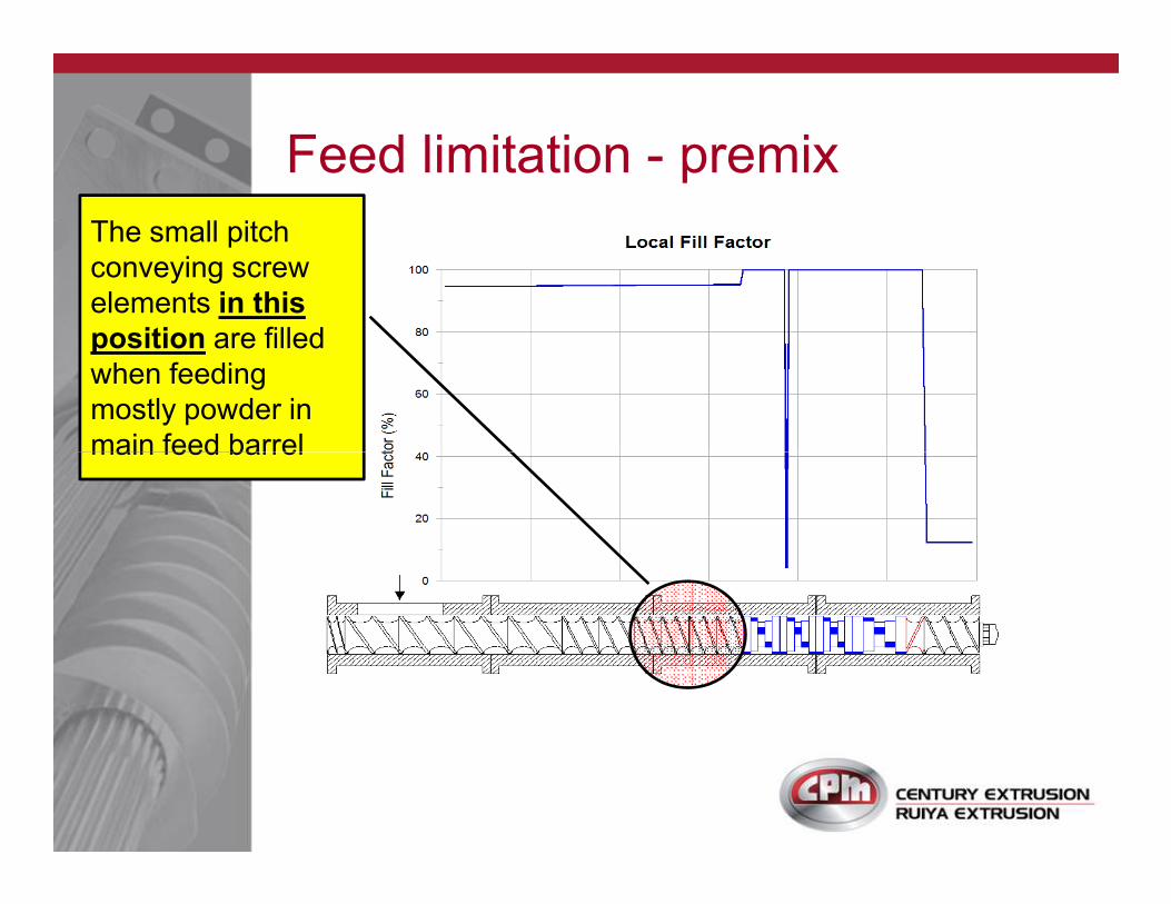
Feed limitation - premix
The small pitch
conveying screw
elements in this
position are filled
when feeding
mostly powder in
main feed barrelmain feed barrel
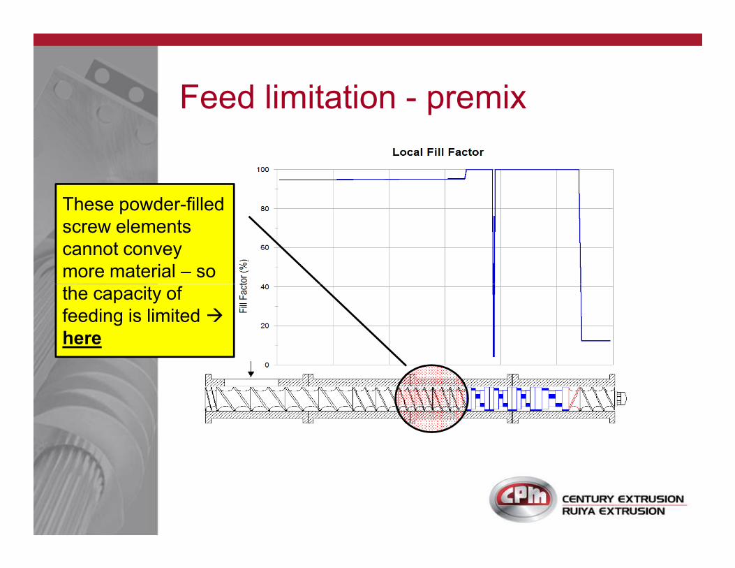
Feed limitation - premix
These powder-filled
screw elements
cannot convey
more material – so
the capacity of the capacity of
feeding is limited �
here
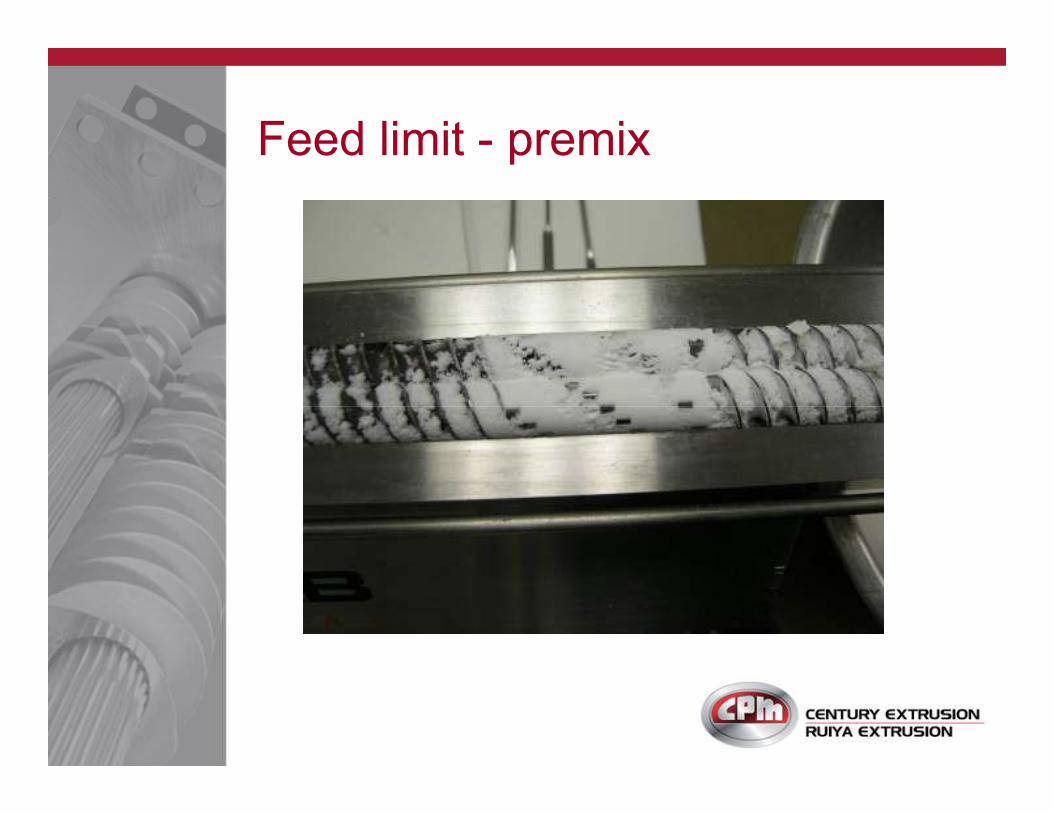
Feed limit - premix

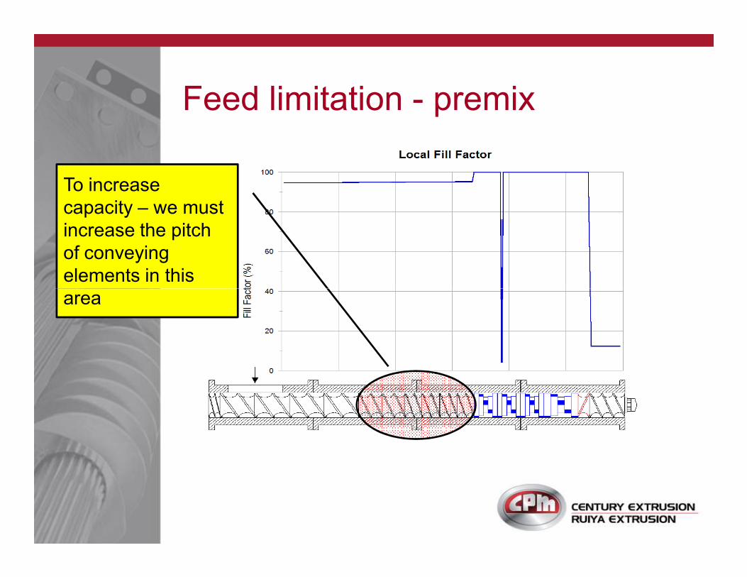
Feed limitation - premix
To increase
capacity – we must
increase the pitch
of conveying
elements in this
areaarea
Feed limitation - premix
To increase
capacity – we must
increase the pitch
of conveying
elements in this
areaarea

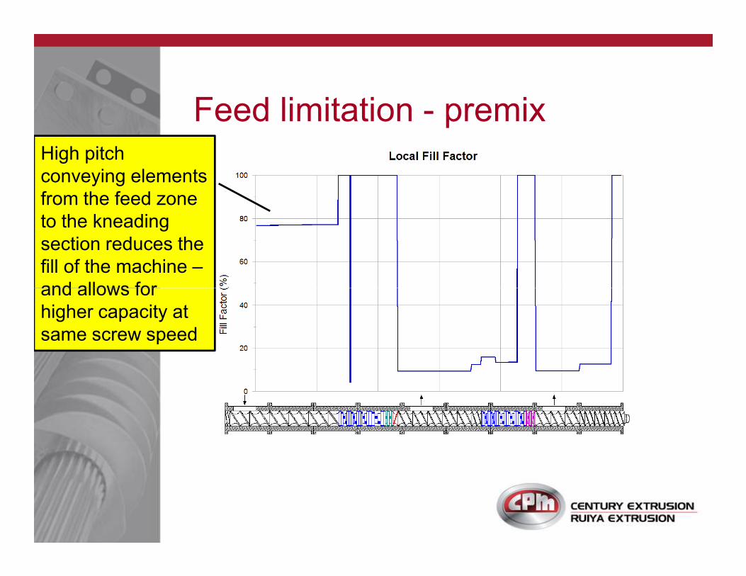
Feed limitation - premix High pitch
conveying elements
from the feed zone
to the kneading
section reduces the
fill of the machine –
and allows for and allows for
higher capacity at
same screw speed
Feed limitation - premix High pitch
conveying elements
from the feed zone
to the kneading
section reduces the
fill of the machine –
and allows for and allows for
higher capacity at
same screw speed
The screw design must use the highest pitch
conveying elements from the main feed area all
the way through to the kneading elements
Special design feeding screws can further
increase capacity for formulations with very low
bulk density, less than 0.1 (e.g. silica)
Maximizing capacity - premix
bulk density, less than 0.1 (e.g. silica)
This approach can increase productivity for
existing machines using premix feeding�
The highest capacity is achieved using
downstream feeding with side feeders�
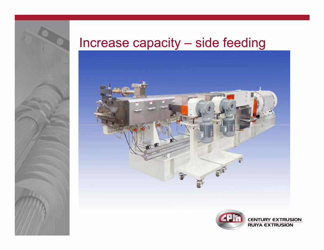
Increase capacity – side feeding
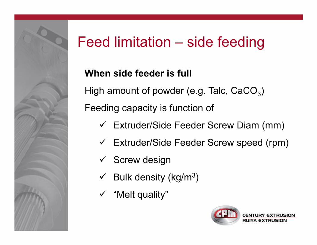
When side feeder is full
High amount of powder (e.g. Talc, CaCO3)
Feeding capacity is function of
� Extruder/Side Feeder Screw Diam (mm)
Feed limitation – side feeding
� Extruder/Side Feeder Screw Diam (mm)
� Extruder/Side Feeder Screw speed (rpm)
� Screw design
� Bulk density (kg/m3)
� “Melt quality”
Example: side feeding limitation
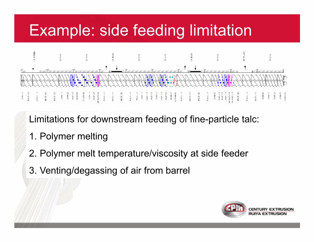
Limitations for downstream feeding of fine-particle talc:Limitations for downstream feeding of fine-particle talc:
1. Polymer melting
2. Polymer melt temperature/viscosity at side feeder
3. Venting/degassing of air from barrel

If polymer is not 100% molten at side feeder:
Problem: polymer melting
If polymer is not 100% molten at side feeder:
1. Downstream mixing of talc results in poor dispersion
2. Atmospheric vent does not work (material comes out)
MUST VISUALLY CONFIRM 100% MELTED POLYMER AT
SIDE FEEDER (there must be NO un-melted resin at this
point)
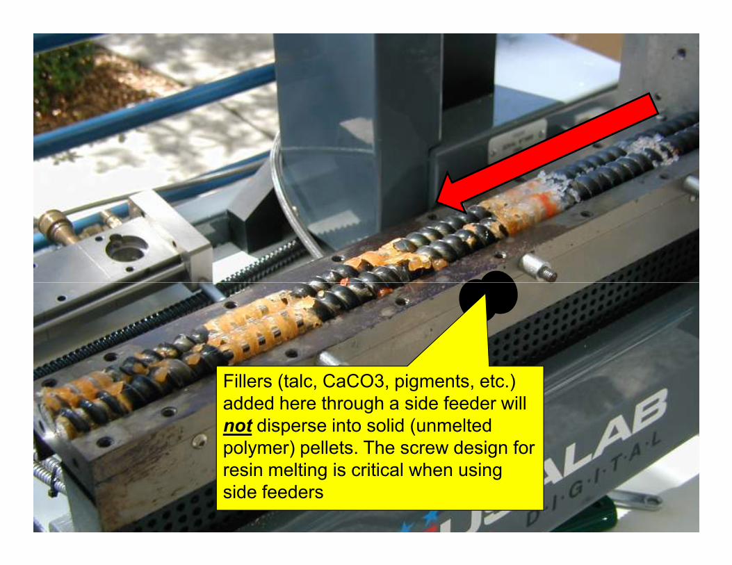
Fillers (talc, CaCO3, pigments, etc.)
added here through a side feeder will
not disperse into solid (unmelted
polymer) pellets. The screw design for
resin melting is critical when using
side feeders
If melt temperature is not high enough at side feeder:
Problem: polymer melt temperature
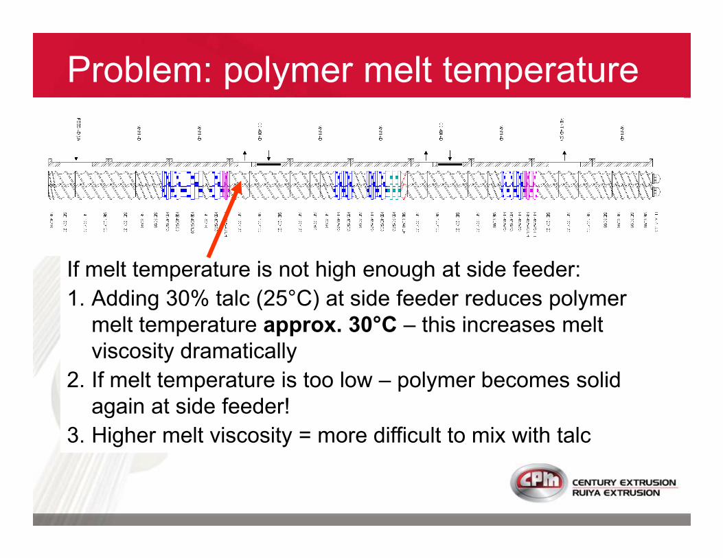
If melt temperature is not high enough at side feeder:
1. Adding 30% talc (25°C) at side feeder reduces polymer
melt temperature approx. 30°C – this increases melt
viscosity dramatically
2. If melt temperature is too low – polymer becomes solid
again at side feeder!
3. Higher melt viscosity = more difficult to mix with talc
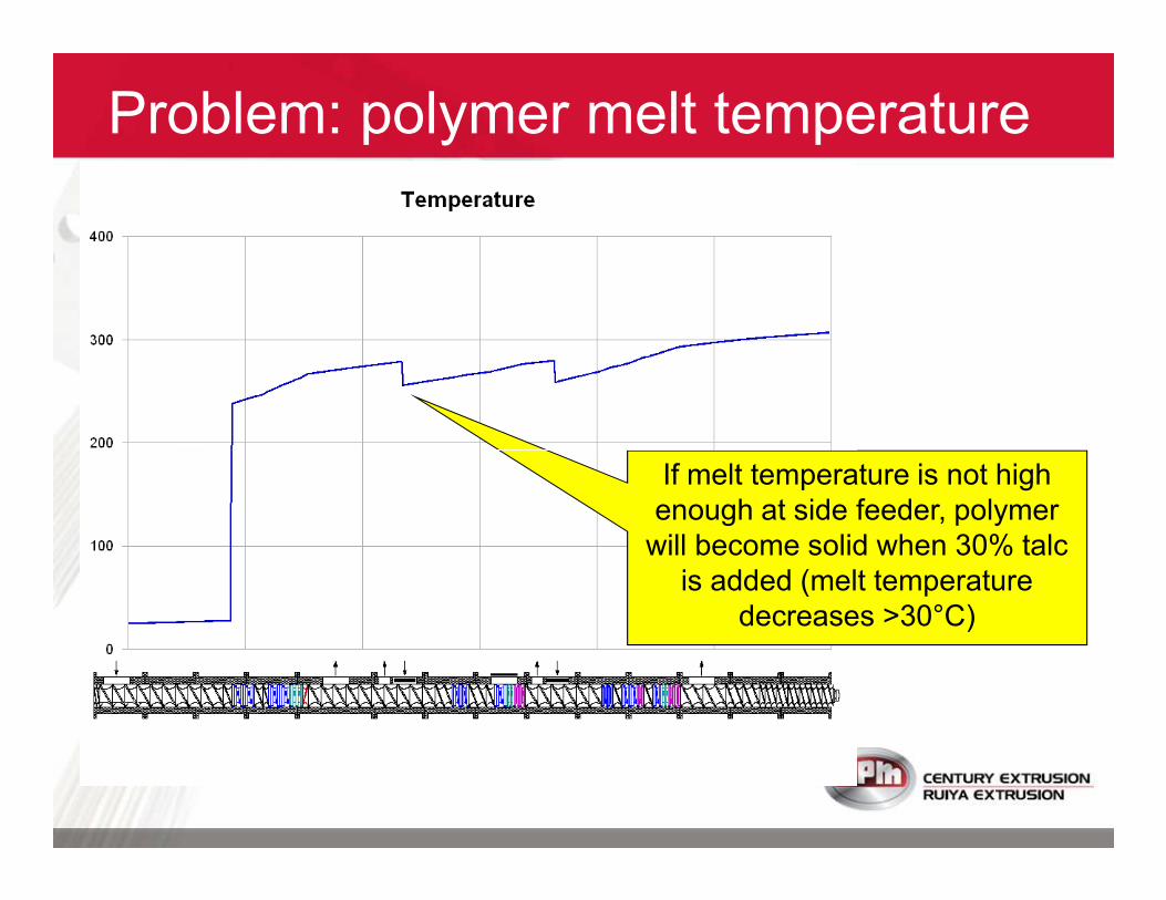
Problem: polymer melt temperature
If melt temperature is not high
enough at side feeder, polymer
will become solid when 30% talc
is added (melt temperature
decreases >30°C)
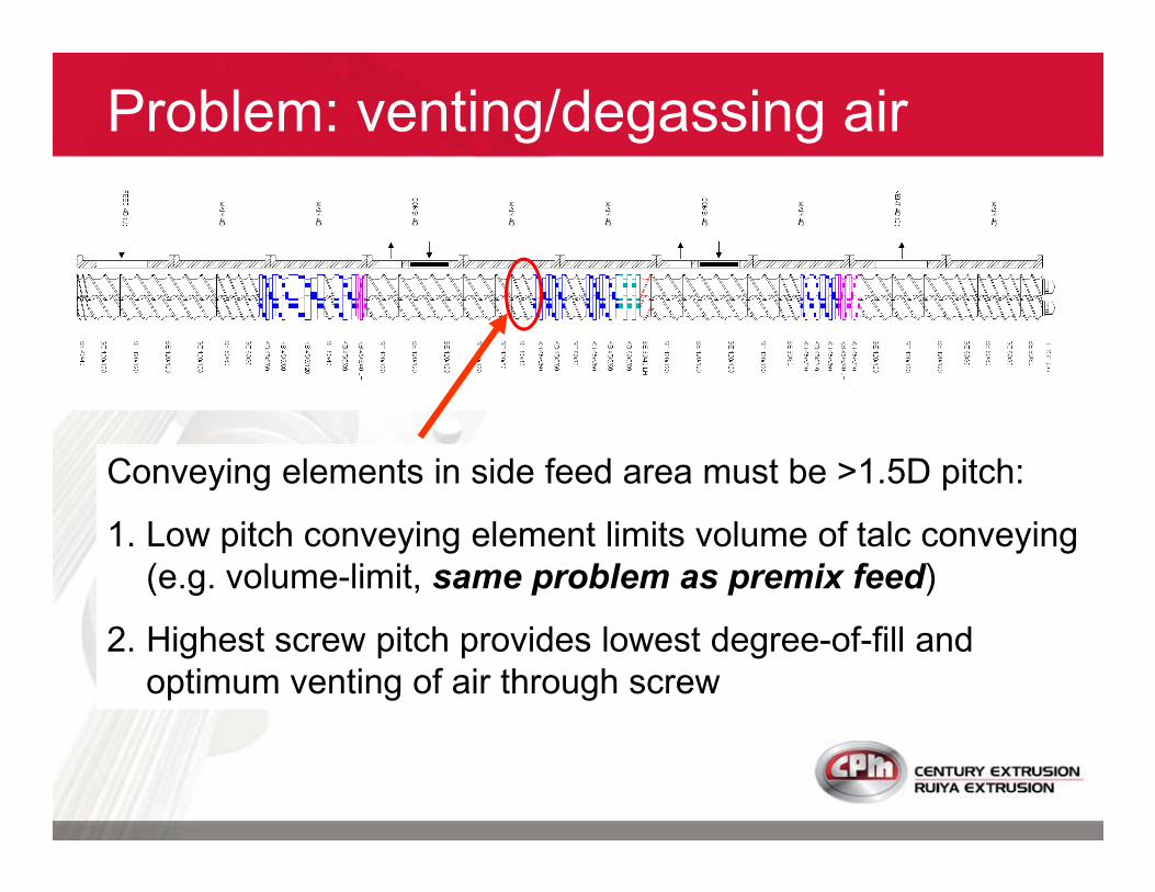
Problem: venting/degassing air
Conveying elements in side feed area must be >1.5D pitch:
1. Low pitch conveying element limits volume of talc conveying
(e.g. volume-limit, same problem as premix feed)
2. Highest screw pitch provides lowest degree-of-fill and
optimum venting of air through screw
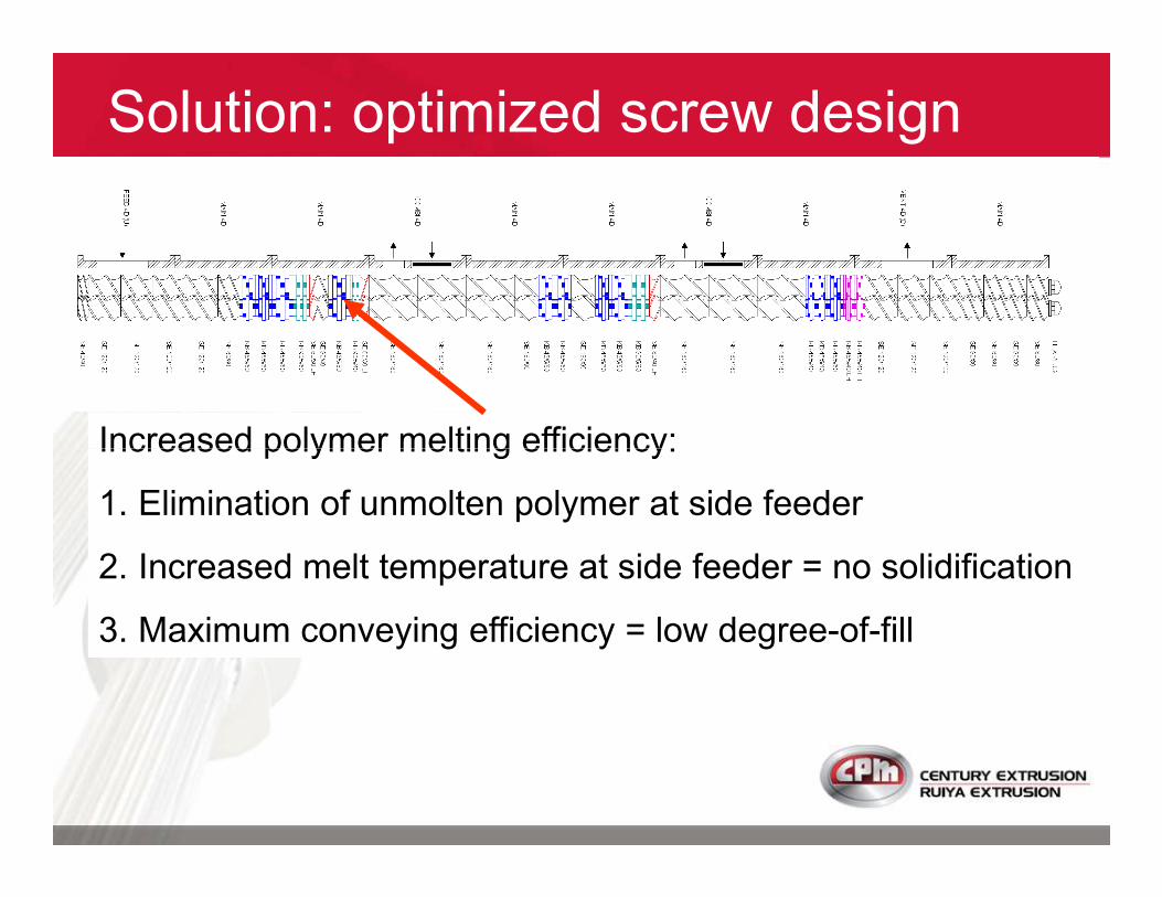
Solution: optimized screw design
Increased polymer melting efficiency:Increased polymer melting efficiency:
1. Elimination of unmolten polymer at side feeder
2. Increased melt temperature at side feeder = no solidification
3. Maximum conveying efficiency = low degree-of-fill
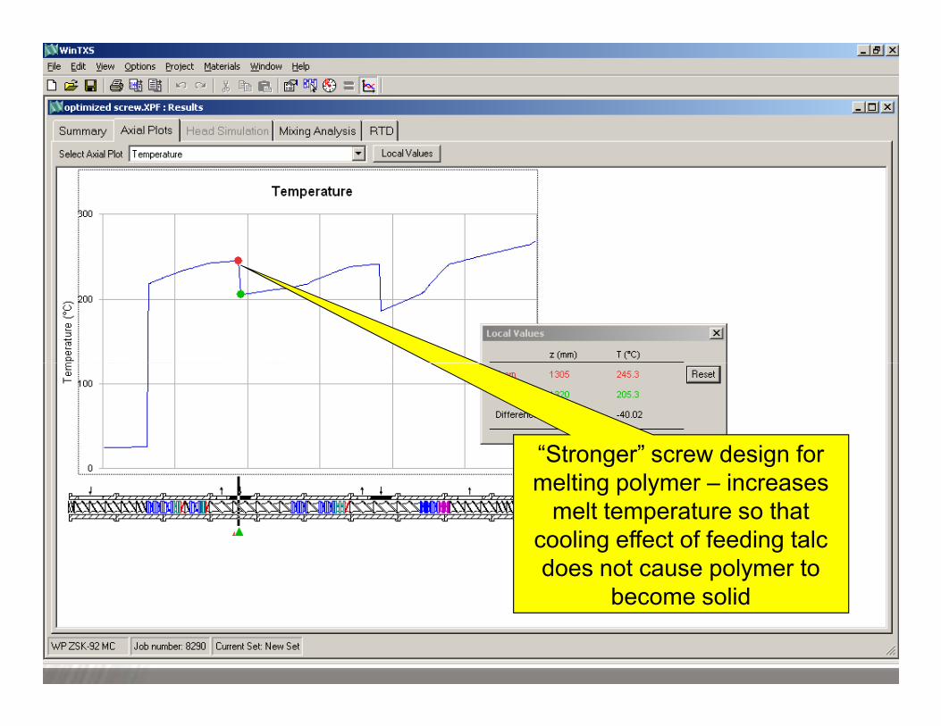
“Stronger” screw design for
melting polymer – increases
melt temperature so that
cooling effect of feeding talc
does not cause polymer to
become solid
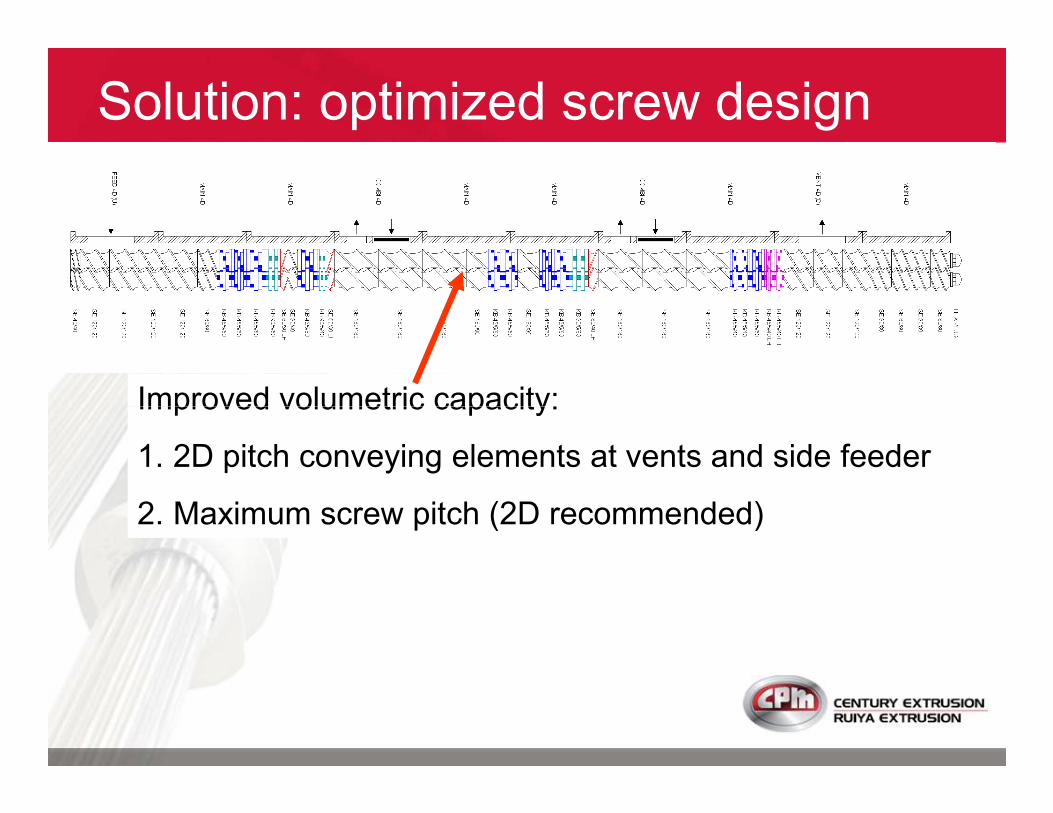
Solution: optimized screw design
Improved volumetric capacity:Improved volumetric capacity:
1. 2D pitch conveying elements at vents and side feeder
2. Maximum screw pitch (2D recommended)
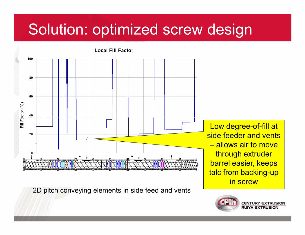
Solution: optimized screw design
Low degree-of-fill at
side feeder and vents
– allows air to move
through extruder
barrel easier, keeps
talc from backing-up
in screw2D pitch conveying elements in side feed and vents
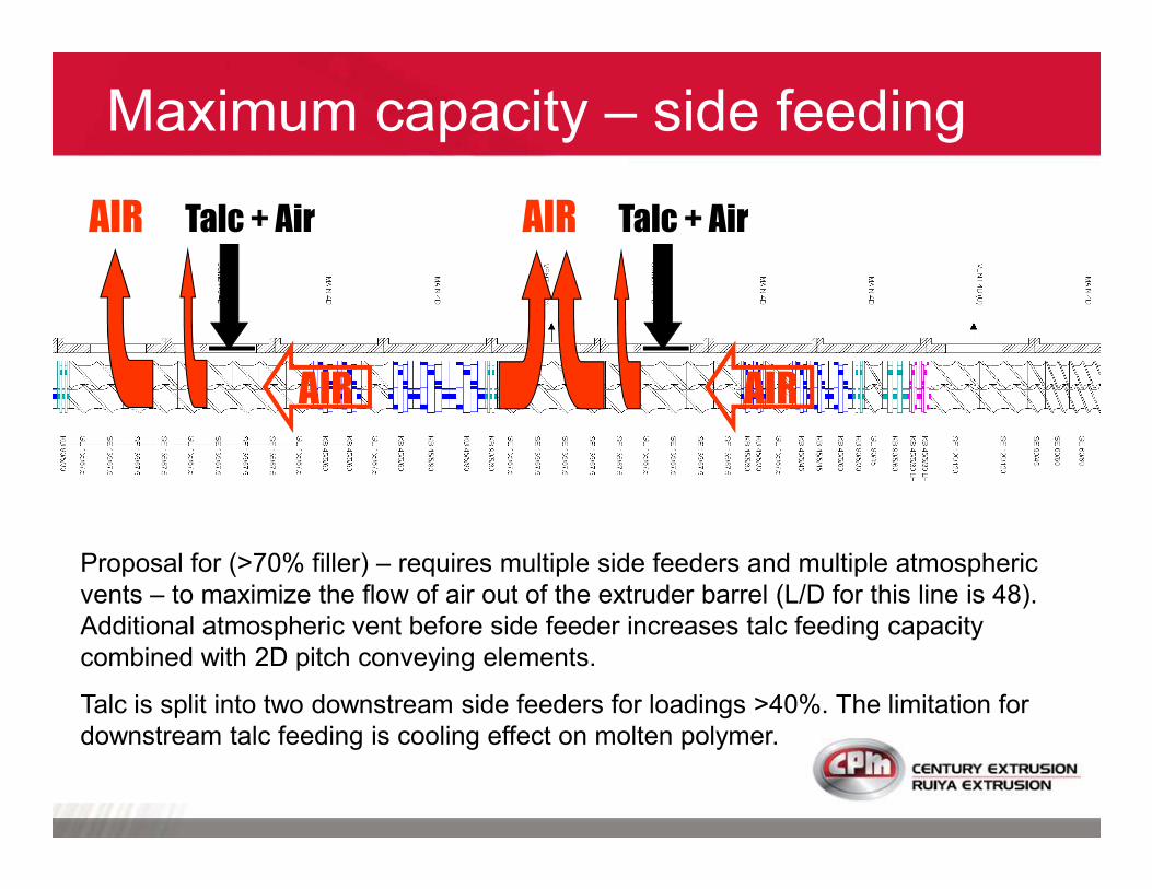
Maximum capacity – side feeding
Talc + Air Talc + Air
AIR AIR
AIR AIR
Proposal for (>70% filler) – requires multiple side feeders and multiple atmospheric
vents – to maximize the flow of air out of the extruder barrel (L/D for this line is 48).
Additional atmospheric vent before side feeder increases talc feeding capacity
combined with 2D pitch conveying elements.
Talc is split into two downstream side feeders for loadings >40%. The limitation for
downstream talc feeding is cooling effect on molten polymer.
Maximum capacity – side feeding
� Modification of screw design to provide 2D screw pitch throughout the side feed/vent areas will provide increased capacity for talc and glass feeding.
� Modification of the melting section of screw designs will also improve talc feeding and increase capacity (you should visually confirm presence of any unmelted polymer at side feeder with current screw design).polymer at side feeder with current screw design).
� Machine configuration includes multiple vent openings (upstream and downstream of side feeders) and these types of screw configurations designed to optimize fine-particle talc feeding and maximize machine capacity.

The production capacity can be limited by torque
(motor power) when compoundingD
� polymers with high melt viscosity
� fillers with high bulk density (e.g. TiO2)
Maximize capacity – torque limit
� with side feeders
� temperature-sensitive additives (e.g. FR)
In these cases, extruders with high specific
torque (Nm/cm3) will provide more capacity
The installed power (kW) for a given size extruder
is a function of
� screw diameter
� screw speed (higher speed = higher kW)
Specific torque (torque density)
� gearbox technology
� screw shaft metallurgy
When compounding low-bulk density fillers or
premix feeding, high screw speed (>600 rpm)
can also provide increased capacity
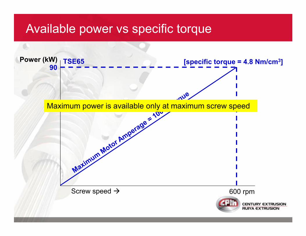
90TSE65Power (kW)
Available power vs specific torque
[specific torque = 4.8 Nm/cm3]
Maximum power is available only at maximum screw speed
600 rpmScrew speed �
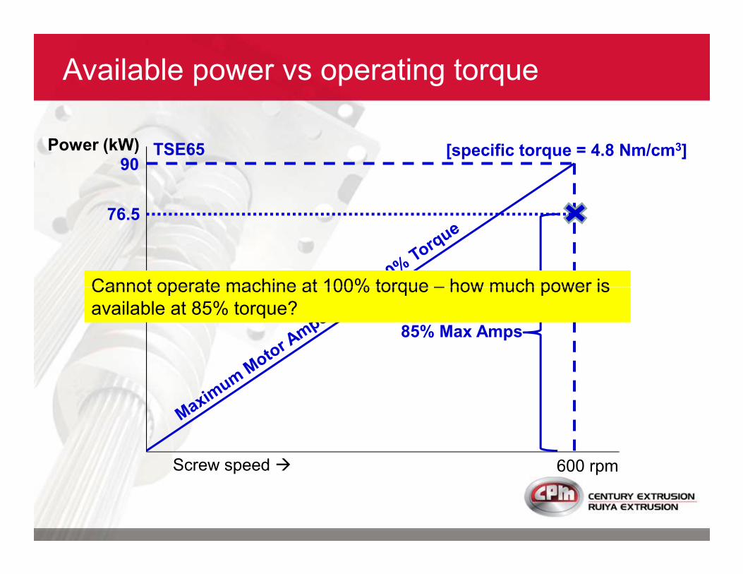
90TSE65Power (kW)
Available power vs operating torque
[specific torque = 4.8 Nm/cm3]
76.5
Cannot operate machine at 100% torque – how much power is
600 rpmScrew speed �
85% Max Amps
Cannot operate machine at 100% torque – how much power is
available at 85% torque?
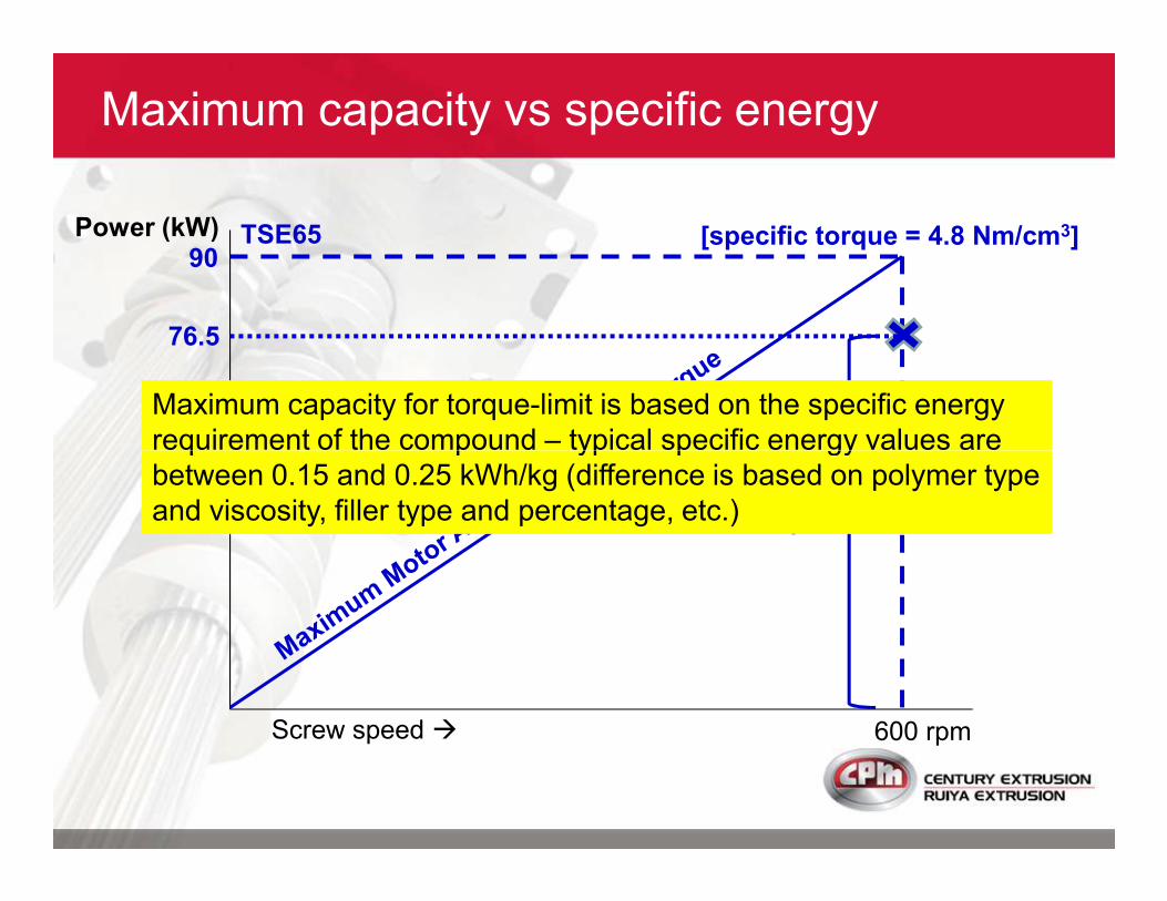
90TSE65Power (kW)
Maximum capacity vs specific energy
[specific torque = 4.8 Nm/cm3]
76.5
Maximum capacity for torque-limit is based on the specific energy
requirement of the compound – typical specific energy values are
600 rpmScrew speed �
85% Max Amps
requirement of the compound – typical specific energy values are
between 0.15 and 0.25 kWh/kg (difference is based on polymer type
and viscosity, filler type and percentage, etc.)
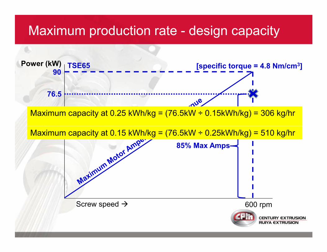
90TSE65Power (kW)
Maximum production rate - design capacity
[specific torque = 4.8 Nm/cm3]
76.5
Maximum capacity at 0.25 kWh/kg = (76.5kW ÷ 0.15kWh/kg) = 306 kg/hr
600 rpmScrew speed �
85% Max Amps
Maximum capacity at 0.15 kWh/kg = (76.5kW ÷ 0.25kWh/kg) = 510 kg/hr
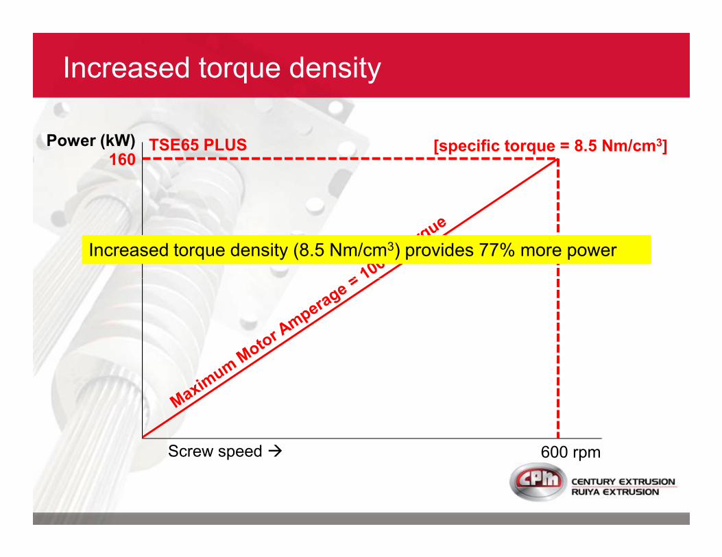
160TSE65 PLUSPower (kW)
Increased torque density
[specific torque = 8.5 Nm/cm3]
Increased torque density (8.5 Nm/cm3) provides 77% more power
600 rpmScrew speed �
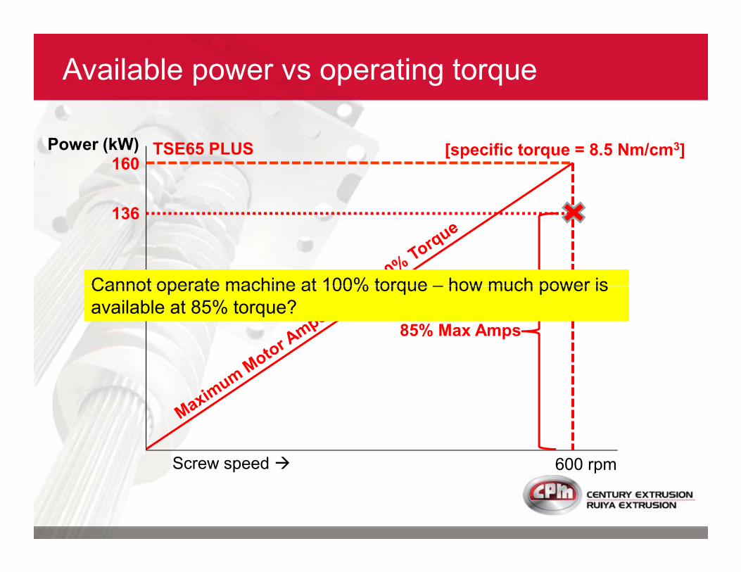
160TSE65 PLUSPower (kW)
Available power vs operating torque
[specific torque = 8.5 Nm/cm3]
136
Cannot operate machine at 100% torque – how much power is
600 rpmScrew speed �
85% Max Amps
Cannot operate machine at 100% torque – how much power is
available at 85% torque?
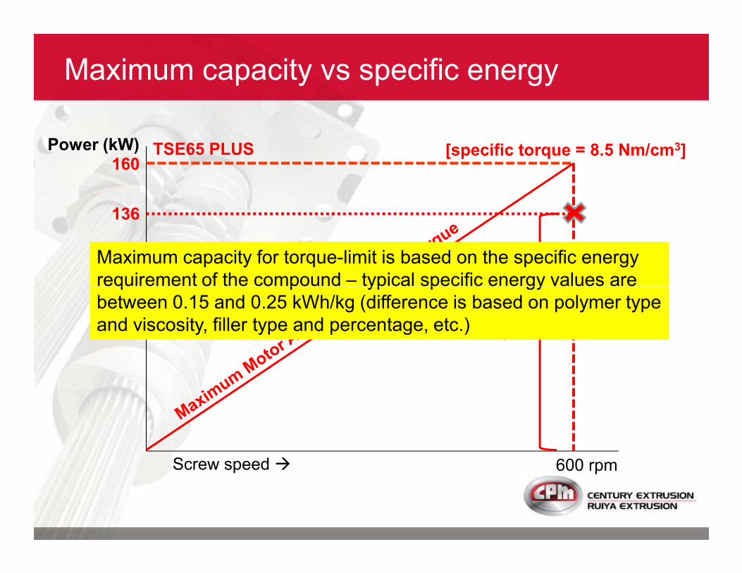
160TSE65 PLUSPower (kW) [specific torque = 8.5 Nm/cm3]
136
Maximum capacity for torque-limit is based on the specific energy
requirement of the compound – typical specific energy values are
Maximum capacity vs specific energy
600 rpmScrew speed �
85% Max Amps
requirement of the compound – typical specific energy values are
between 0.15 and 0.25 kWh/kg (difference is based on polymer type
and viscosity, filler type and percentage, etc.)
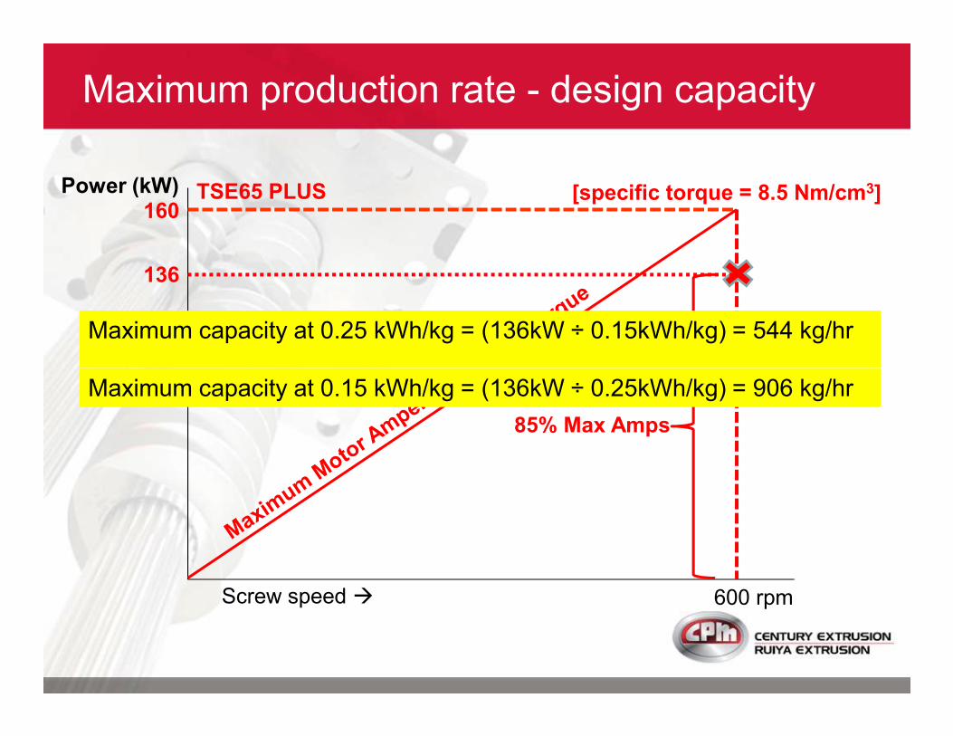
160TSE65 PLUSPower (kW) [specific torque = 8.5 Nm/cm3]
136
Maximum capacity at 0.25 kWh/kg = (136kW ÷ 0.15kWh/kg) = 544 kg/hr
Maximum production rate - design capacity
600 rpmScrew speed �
85% Max Amps
Maximum capacity at 0.15 kWh/kg = (136kW ÷ 0.25kWh/kg) = 906 kg/hr

315RXT65Power (kW)
Capacity increase with high torque machine
160TSE65 PLUS
[specific torque = 11.0 Nm/cm3]
[specific torque = 8.5 Nm/cm3]
1000 rpmScrew speed �
160
90
TSE65 PLUS
TSE65
600 rpm
[specific torque = 4.8 Nm/cm3]
[specific torque = 8.5 Nm/cm3]
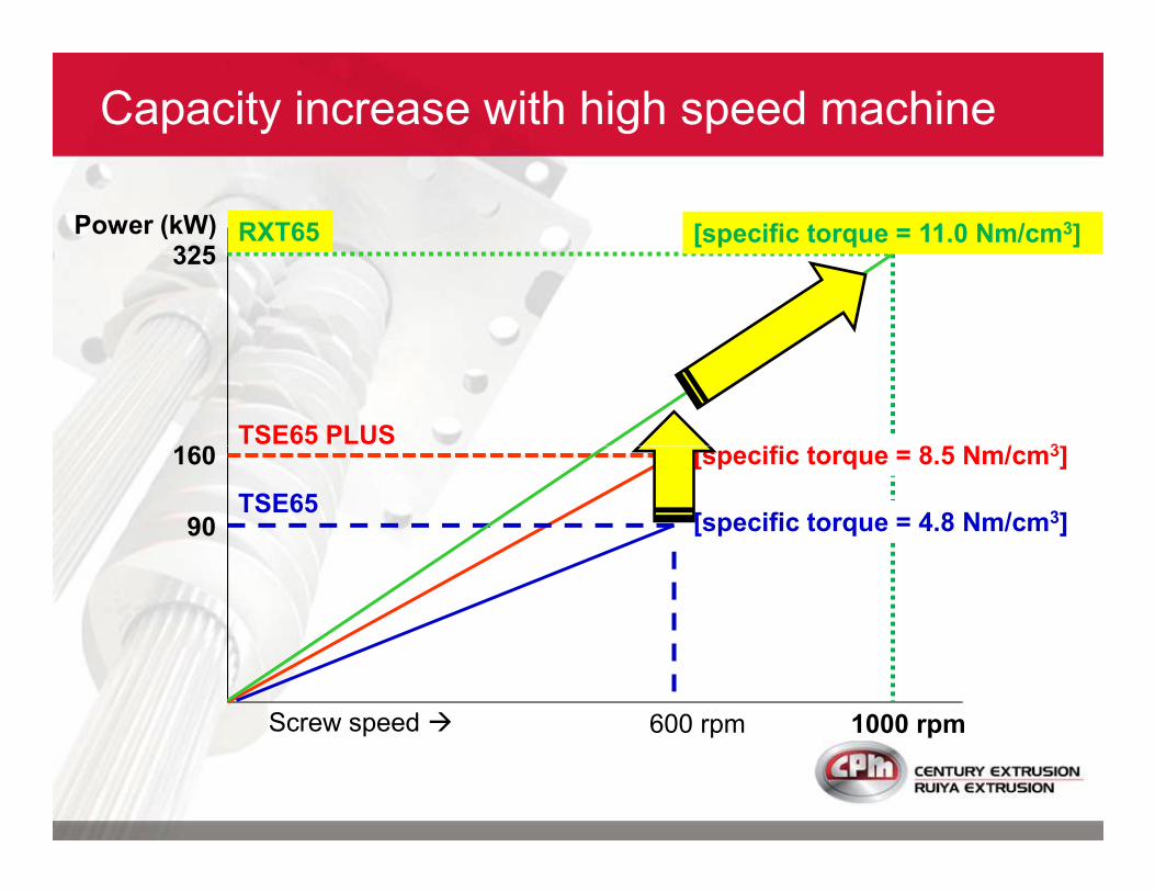
325Power (kW)
160TSE65 PLUS
[specific torque = 8.5 Nm/cm3]
Capacity increase with high speed machine
RXT65 [specific torque = 11.0 Nm/cm3]
1000 rpmScrew speed �
160
90
TSE65 PLUS
TSE65
600 rpm
[specific torque = 4.8 Nm/cm3]
[specific torque = 8.5 Nm/cm3]
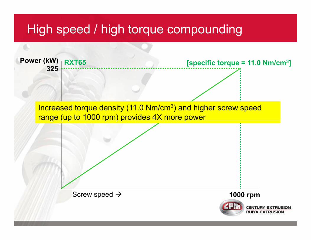
325RXT65Power (kW) [specific torque = 11.0 Nm/cm3]
High speed / high torque compounding
Increased torque density (11.0 Nm/cm3) and higher screw speed
range (up to 1000 rpm) provides 4X more power
1000 rpmScrew speed �
range (up to 1000 rpm) provides 4X more power

325RXT65Power (kW) [specific torque = 11.0 Nm/cm3]
Capacity increase with high speed machine
80% Max Screw Speed
Available power at 80% maximum screw speed (e.g. compound
quality limited by melt temperature)
260
1000 rpmScrew speed � 800 rpm
quality limited by melt temperature)
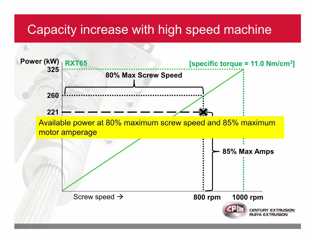
325RXT65Power (kW) [specific torque = 11.0 Nm/cm3]
Capacity increase with high speed machine
80% Max Screw Speed
260
221
Available power at 80% maximum screw speed and 85% maximum
1000 rpmScrew speed �
85% Max Amps
800 rpm
Available power at 80% maximum screw speed and 85% maximum
motor amperage
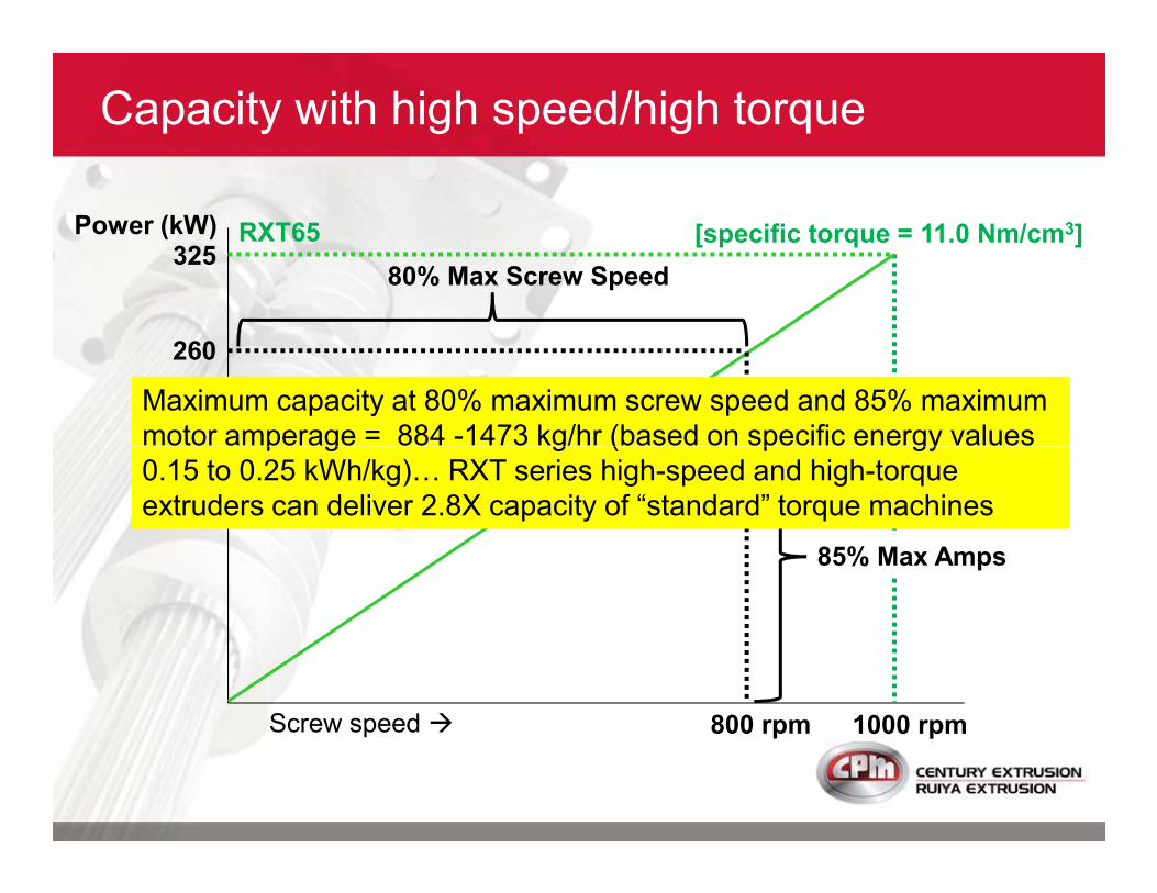
325RXT65Power (kW) [specific torque = 11.0 Nm/cm3]
Capacity with high speed/high torque
80% Max Screw Speed
260
221Maximum capacity at 80% maximum screw speed and 85% maximum
motor amperage = 884 -1473 kg/hr (based on specific energy values
1000 rpmScrew speed �
85% Max Amps
800 rpm
motor amperage = 884 -1473 kg/hr (based on specific energy values
0.15 to 0.25 kWh/kg)D RXT series high-speed and high-torque
extruders can deliver 2.8X capacity of “standard” torque machines
Maximizing Quality
High-quality compound is produced at maximum
capacity with proper extruder configuration, screw
design and operating conditions.
Compound quality and/or capacity will decrease
over time as screws and barrels wear. This over time as screws and barrels wear. This
situation is unavoidable when compounding
abrasive fillers (CaCO3, TiO2, glass fibers, etc.).
Maximizing profitability requires maintaining
both quality and capacity over time�
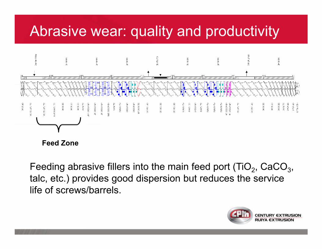
Abrasive wear: quality and productivity
Feed Zone
Feeding abrasive fillers into the main feed port (TiO2, CaCO3,
talc, etc.) provides good dispersion but reduces the service
life of screws/barrels.
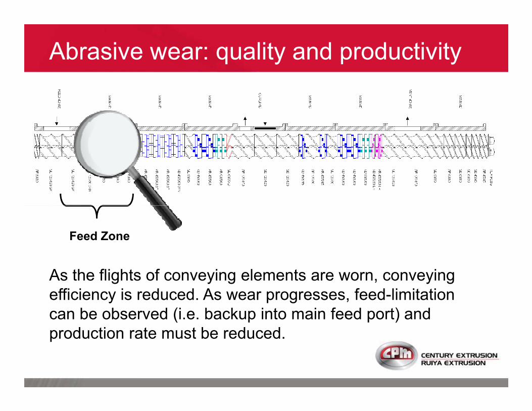
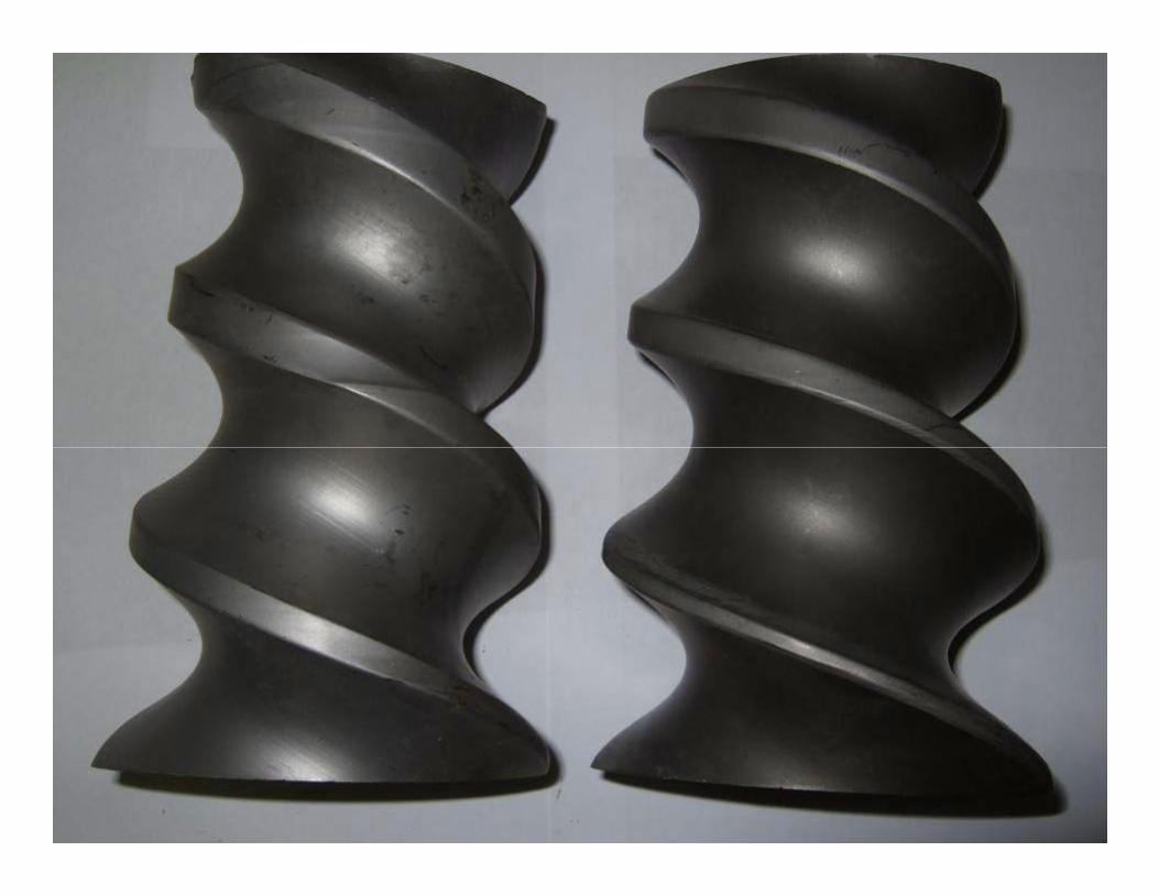
Abrasive wear: quality and productivity
As the flights of conveying elements are worn, conveying
efficiency is reduced. As wear progresses, feed-limitation
can be observed (i.e. backup into main feed port) and
production rate must be reduced.
Feed Zone
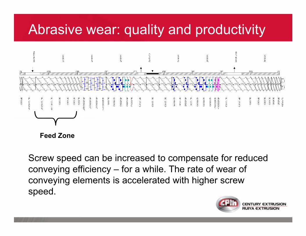
Abrasive wear: quality and productivity
Screw speed can be increased to compensate for reduced
conveying efficiency – for a while. The rate of wear of
conveying elements is accelerated with higher screw
speed.
Feed Zone

Abrasive wear: quality and productivity
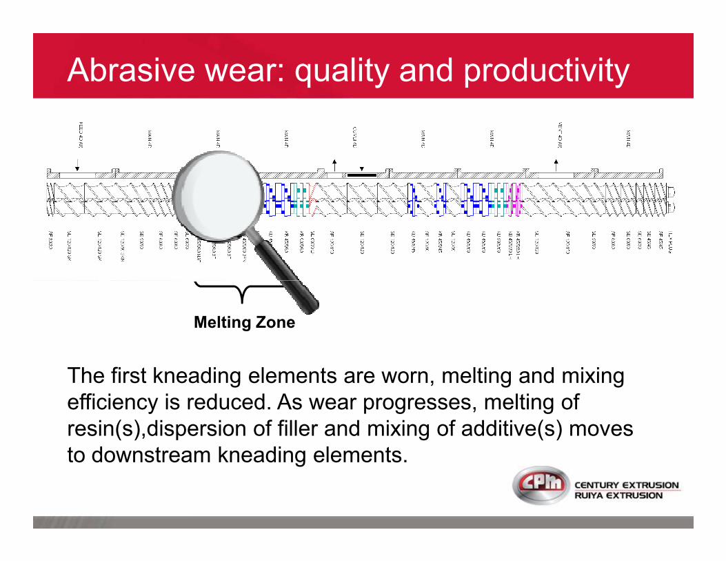
Abrasive wear: quality and productivity
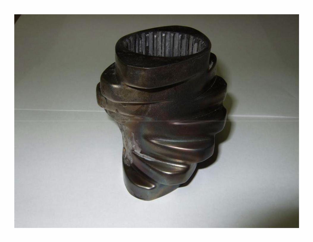
Melting Zone
The first kneading elements are worn, melting and mixing
efficiency is reduced. As wear progresses, melting of
resin(s),dispersion of filler and mixing of additive(s) moves
to downstream kneading elements.

Abrasive wear: quality and productivity
Melting Zone
As wear progresses, deterioration of physical properties
results from decreased melting and mixing. Unmelted resin
appears at side feeder, downstream mixing of fillers is
affected (venting problem at side feeder).
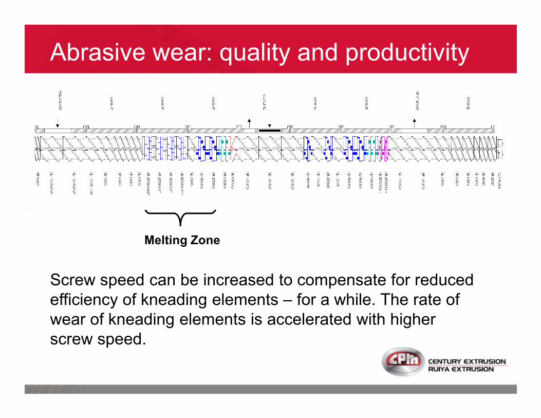
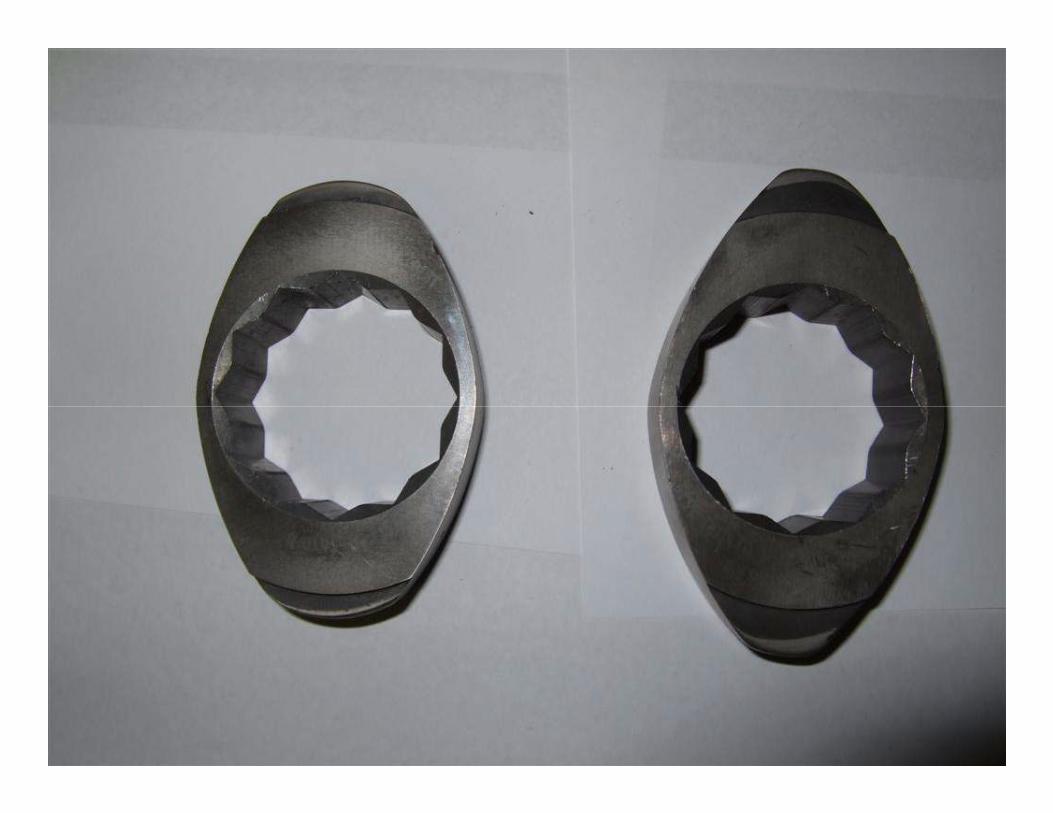
Abrasive wear: quality and productivity
Melting Zone
Screw speed can be increased to compensate for reduced
efficiency of kneading elements – for a while. The rate of
wear of kneading elements is accelerated with higher
screw speed.

As first kneading
elements wear,
melting is delayed –
note mixing cannot
Abrasive wear: quality and productivity
note mixing cannot
start until melting is
completed !
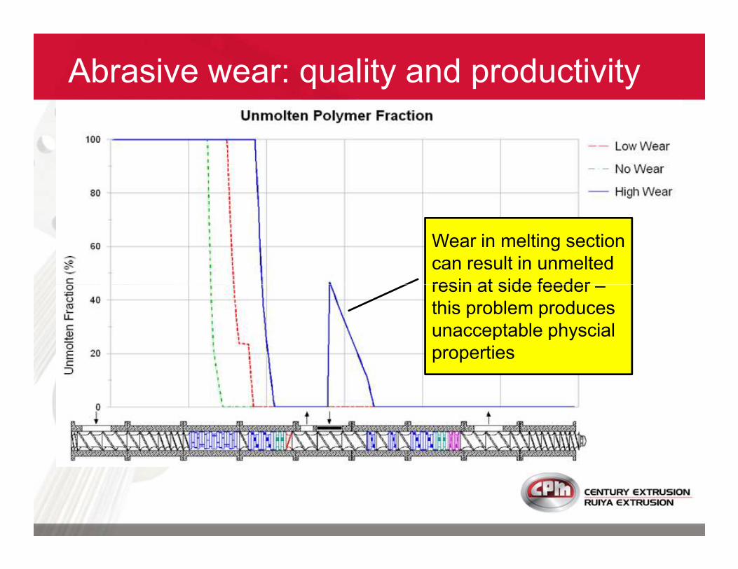
Wear in melting section
can result in unmelted
resin at side feeder –
Abrasive wear: quality and productivity
resin at side feeder –
this problem produces
unacceptable physcial
properties
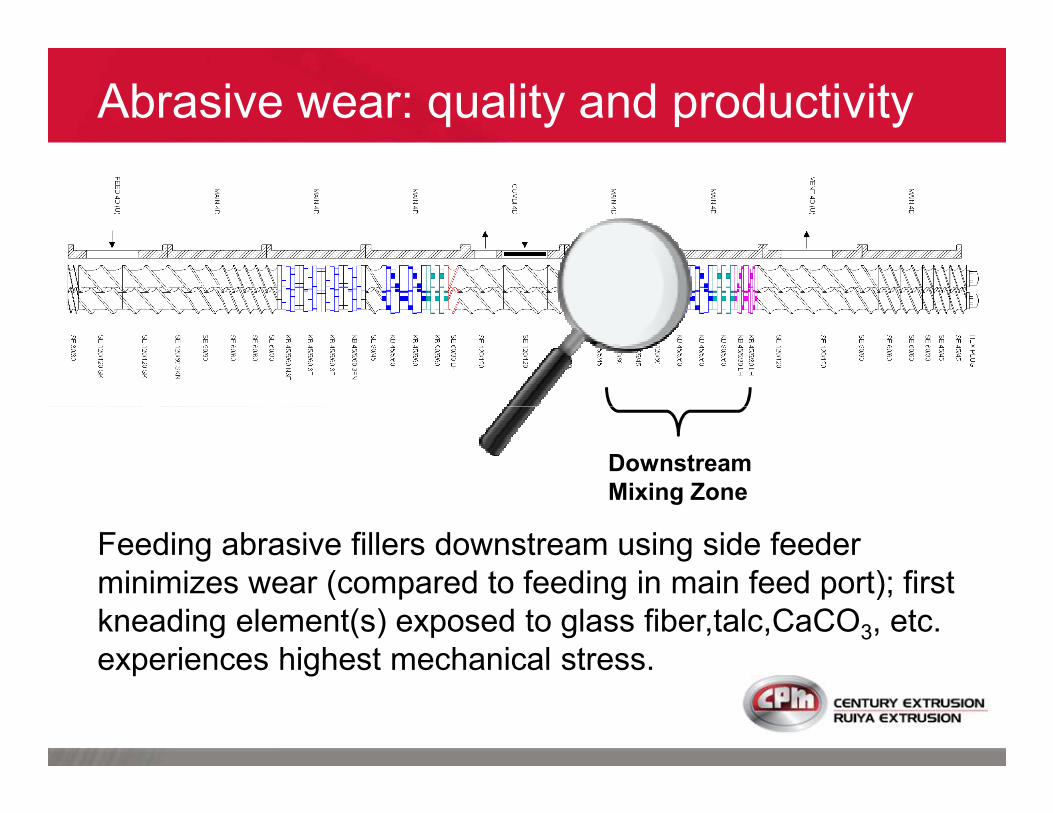
Abrasive wear: quality and productivity
Downstream
Mixing Zone
Feeding abrasive fillers downstream using side feeder
minimizes wear (compared to feeding in main feed port); first
kneading element(s) exposed to glass fiber,talc,CaCO3, etc.
experiences highest mechanical stress.

Abrasive wear: quality and productivity
Downstream
Mixing Zone
Similar to wear of kneading elements in the melting section –
mixing deteriorates as the kneading elements wear and is
observed as decreased physical properties. Filler appears in
vacuum vent or on screens.

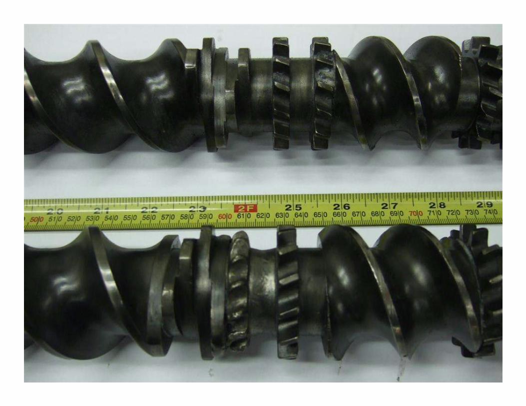
Abrasive wear: quality and productivity
Downstream
Mixing Zone
Similar to wear of conveying elements in the melting section –
conveying efficiency also decreases as these conveying
elements wear and is observed as a feeding limit at the side
feeder (backup); production rate must be reduced.
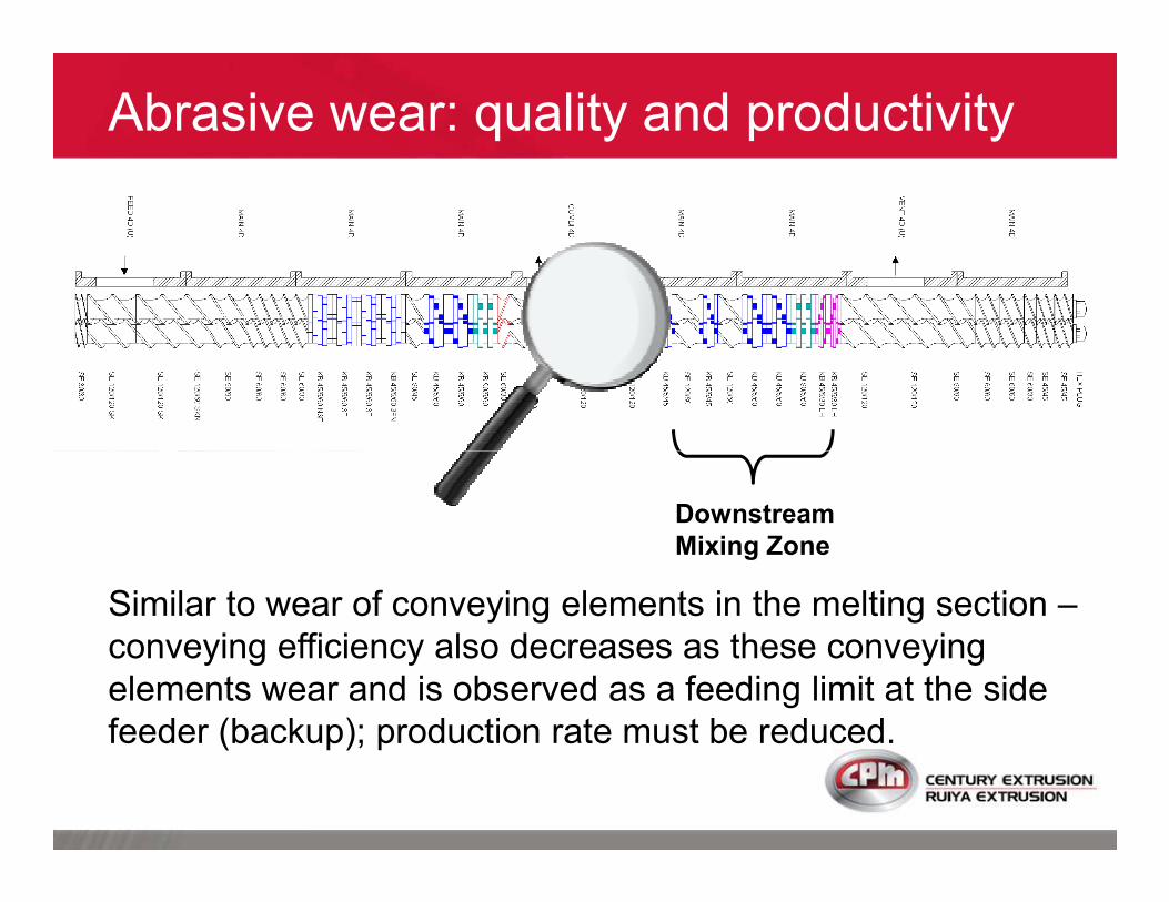
Abrasive wear: quality and productivity
Downstream
Mixing Zone
Screw speed can be increased to compensate for reduced
conveying and/or mixing efficiency – for a while. The rate of
wear of conveying and kneading elements is accelerated with
higher screw speed.
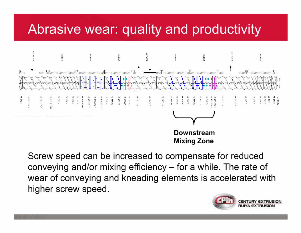
Where is the wear ?
Vacuum Zone
If clearances are enlarged (from abrasive wear) within the restriction
element used to create a melt seal for vacuum, sustainable vacuum level
is reduced.
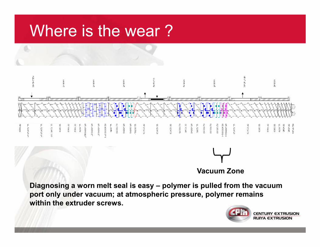
Where is the wear ?
Vacuum Zone
Diagnosing a worn melt seal is easy – polymer is pulled from the vacuum
port only under vacuum; at atmospheric pressure, polymer remains
within the extruder screws.
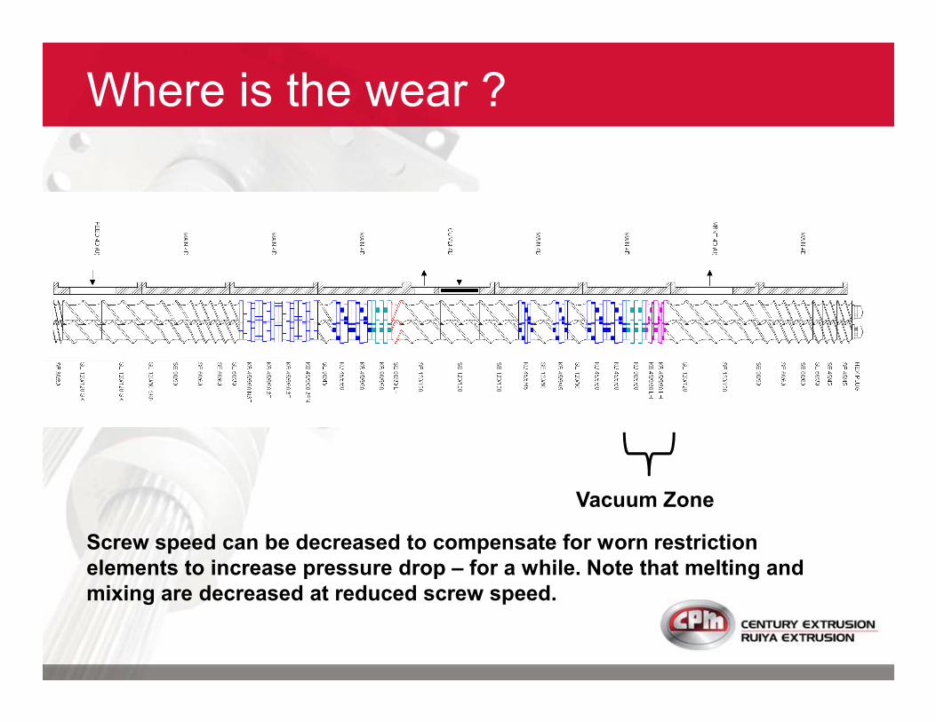
Where is the wear ?
Vacuum Zone
Screw speed can be decreased to compensate for worn restriction
elements to increase pressure drop – for a while. Note that melting and
mixing are decreased at reduced screw speed.
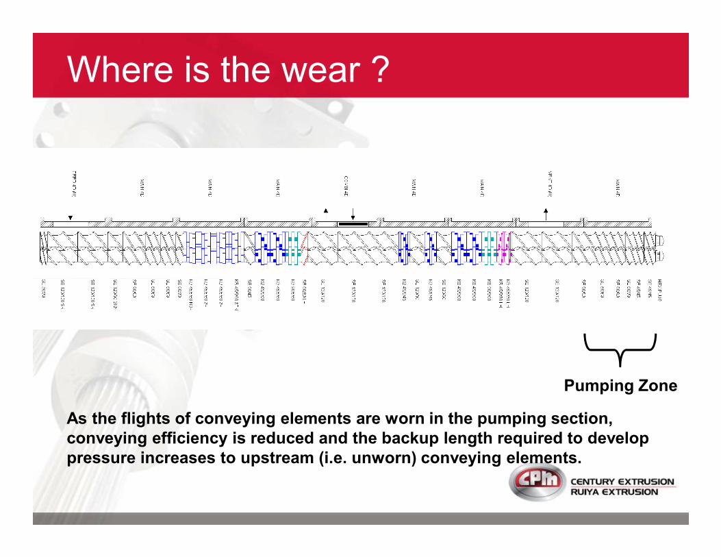
Where is the wear ?
Pumping Zone
As the flights of conveying elements are worn in the pumping section,
conveying efficiency is reduced and the backup length required to develop
pressure increases to upstream (i.e. unworn) conveying elements.

Where is the wear ?
Pumping Zone
Screw speed can be increased to compensate for reduced pumping – for a
while. The rate of wear of conveying elements is accelerated with higher
screw speed.

As wear progresses
in the pumping
Abrasive wear: quality and productivity
in the pumping
section, melt
eventually backs-up
into vacuum vent
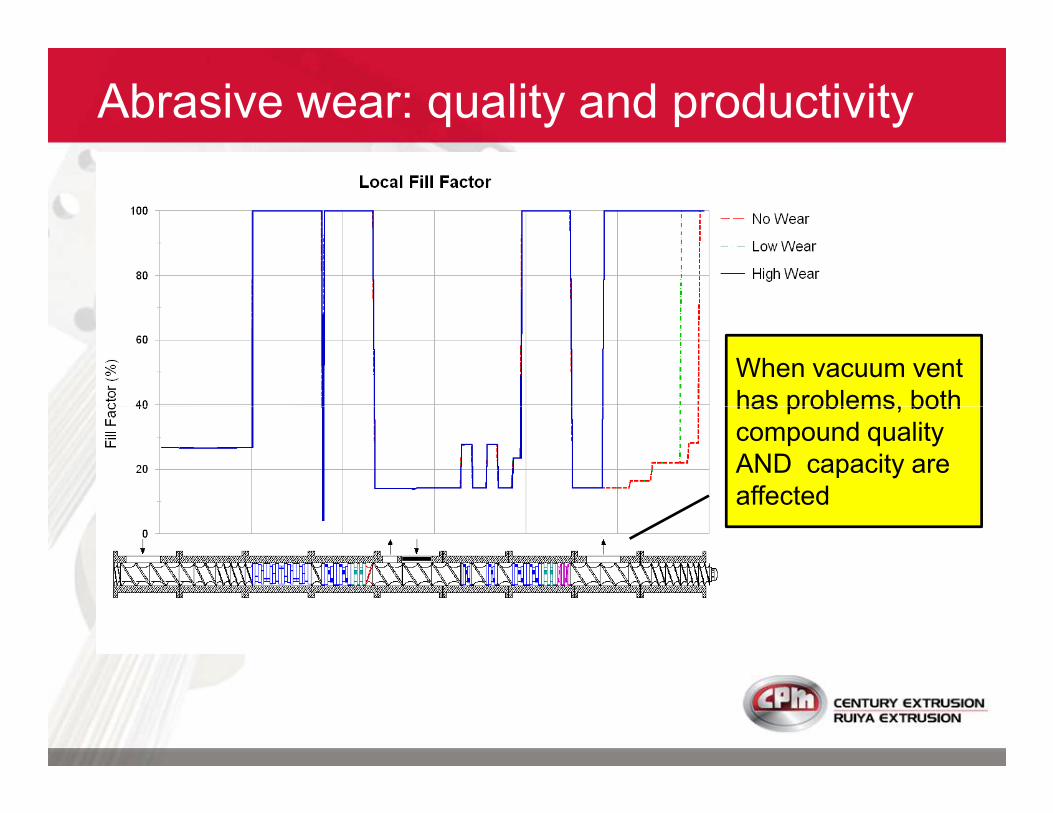
When vacuum vent
has problems, both
Abrasive wear: quality and productivity
has problems, both
compound quality
AND capacity are
affected
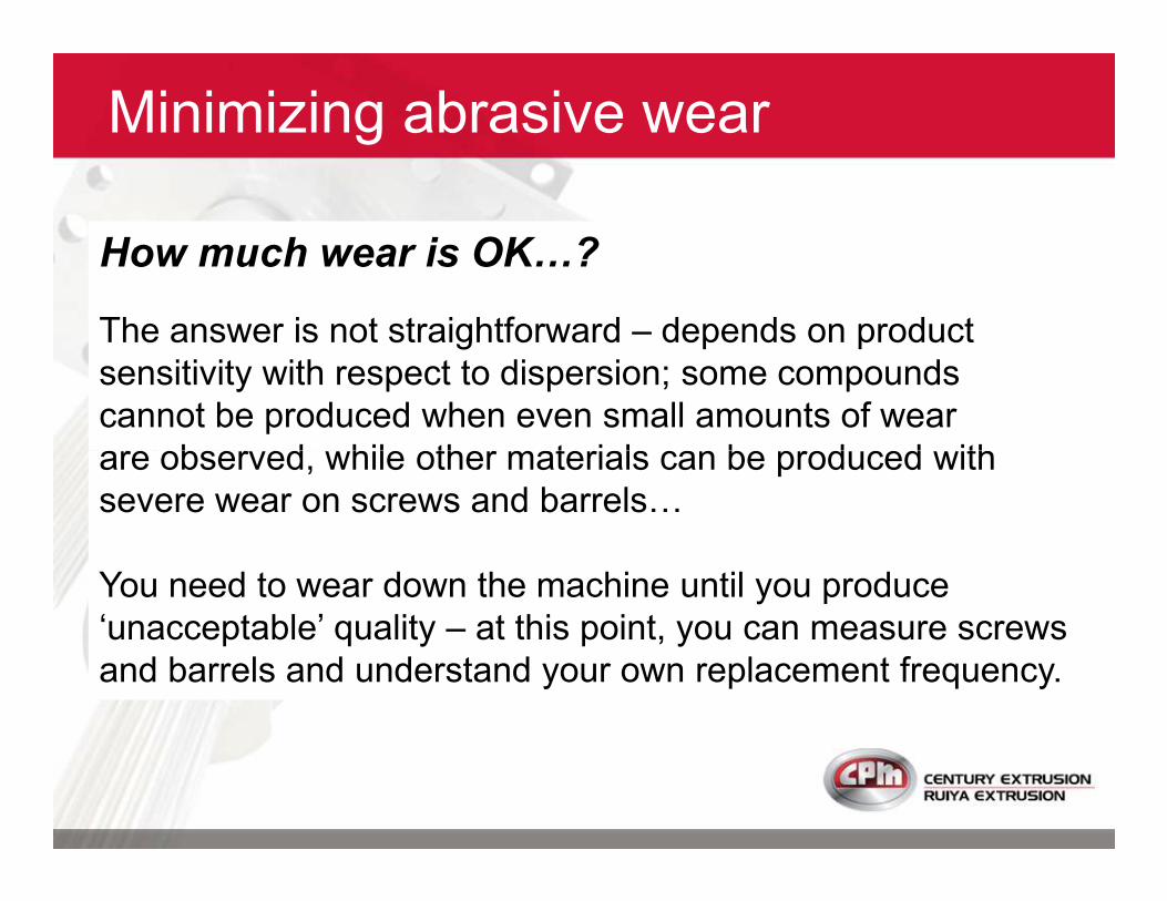
Minimizing abrasive wear
How much wear is OK�?
The answer is not straightforward – depends on product
sensitivity with respect to dispersion; some compounds
cannot be produced when even small amounts of wear
are observed, while other materials can be produced with are observed, while other materials can be produced with
severe wear on screws and barrelsD
You need to wear down the machine until you produce
‘unacceptable’ quality – at this point, you can measure screws
and barrels and understand your own replacement frequency.
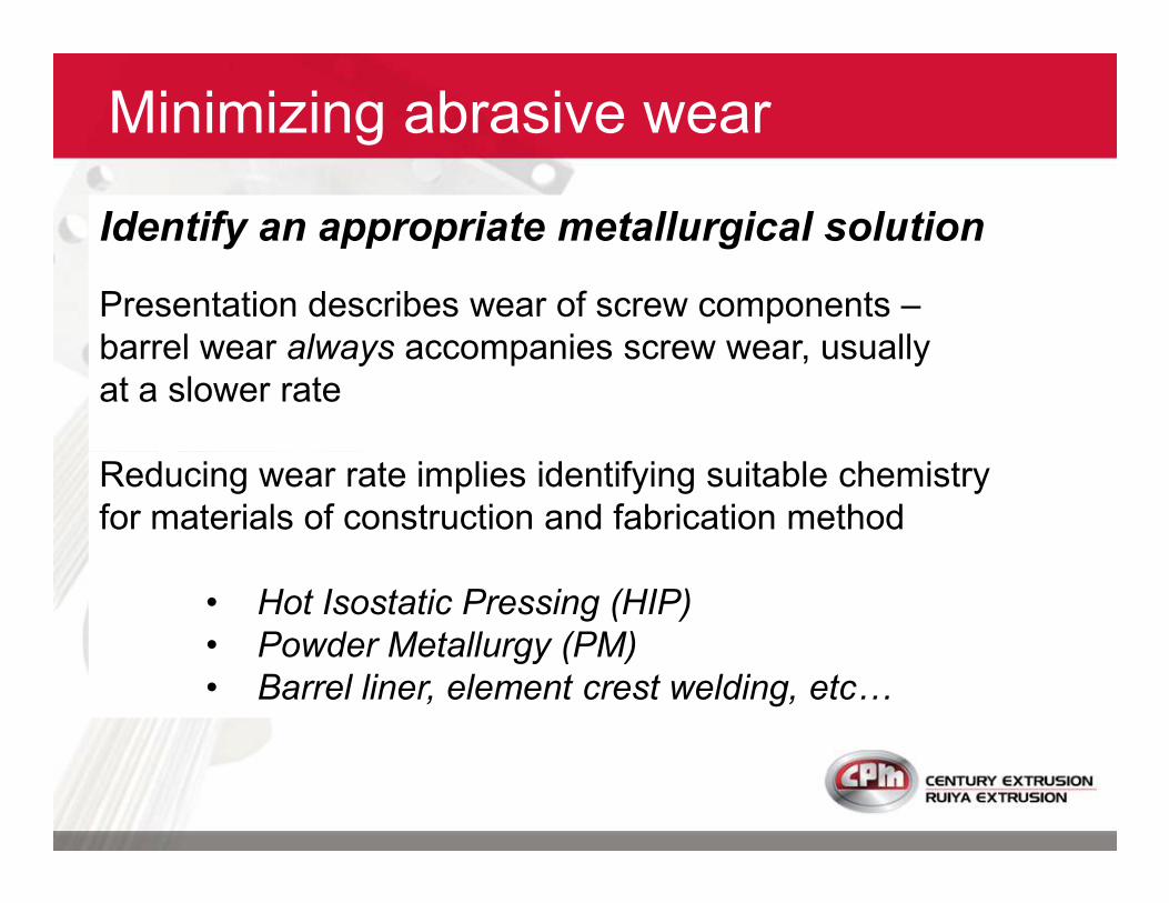
Minimizing abrasive wear
Identify an appropriate metallurgical solution
Presentation describes wear of screw components –
barrel wear always accompanies screw wear, usually
at a slower rate
Reducing wear rate implies identifying suitable chemistry
for materials of construction and fabrication method
• Hot Isostatic Pressing (HIP)
• Powder Metallurgy (PM)
• Barrel liner, element crest welding, etc&
Minimizing Abrasive Wear
Minimizing Abrasive Wear
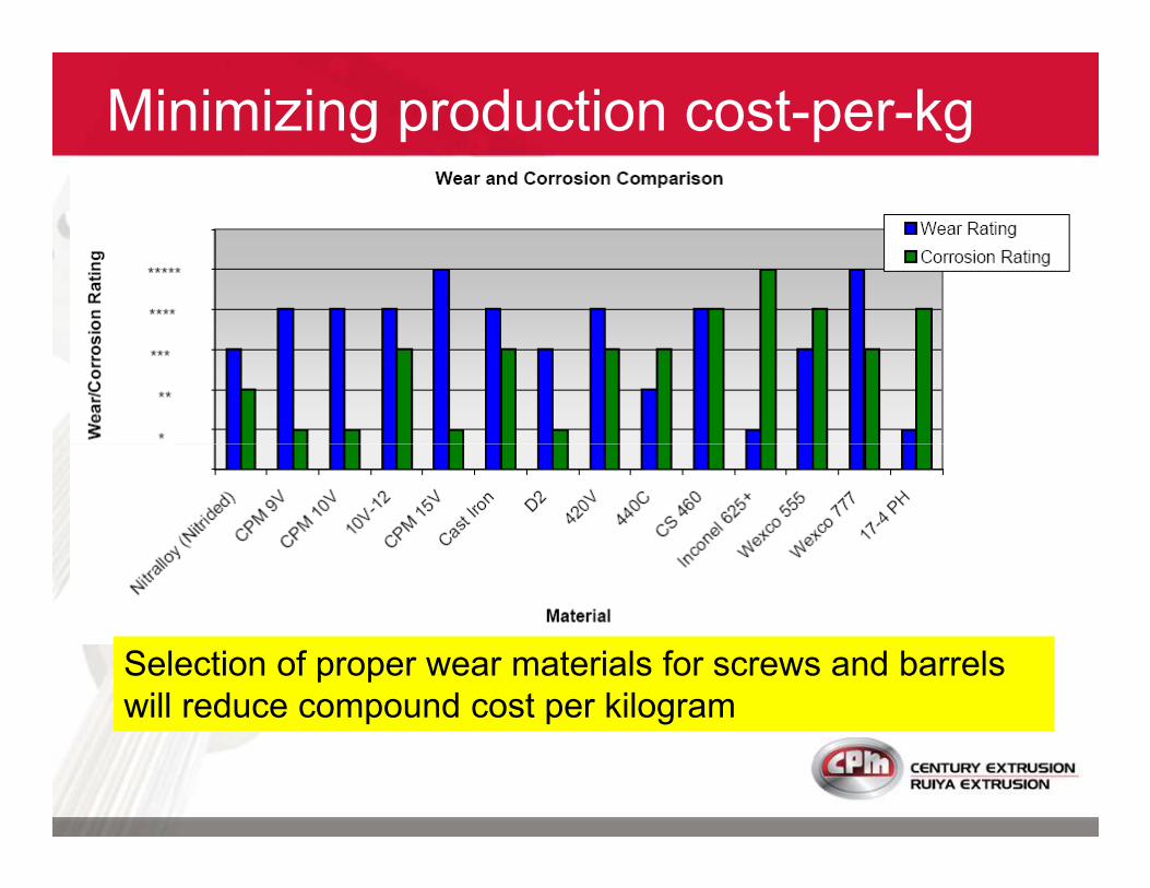
Minimizing production cost-per-kg
Selection of proper wear materials for screws and barrels
will reduce compound cost per kilogram

Maximizing profits
Ruiya Extrusion together with Century Extrusion
have the tools to improve your profitability:
�Screw design expertise
�Cost-effective TSE series extruders
�High-speed/high-torque extruders�High-speed/high-torque extruders
- PLUS series
- APEX/RXT series
�Metallurgical solutions for high-wear
CPM provides our customers with the lowest
cost per productivity!

CPM - your partner in productivity
Questions?
Want to discuss your new project(s)?
Want a copy of this presentation ?
Come to Hall W1, Booth W1E01

Thank you for your attention!Thank you for your attention!