maximising the heat transfer through fins using cfd
TRANSCRIPT

International Journal of Recent advances in Mechanical Engineering (IJMECH) Vol.2, No.3, August 2013
13
MAXIMISING THE HEAT TRANSFER THROUGH FINS
USING CFD AS A TOOL
Sanjay Kumar Sharma1 and Vikas Sharma
2
1,2 Assistant Professor, Department of Mechanical Engineering, Gyan Vihar University,
Jaipur, Rajasthan, India [email protected], [email protected]
ABSTRACT
This study presents the results of computational numerical analysis of air flow and heat transfer in a light
weight automobile engine, considering three different morphology pin fins. A numerical study using Ansys
fluent® (Version 6.3.26) was conducted to find the optimum pin shape based on minimum pressure drop
and maximizing the heat transfer across the Automobile engine body. The results indicate that the drop
shaped pin fins show improved results on the basis of heat transfer and pressure drop by comparing other
fins. The reason behind the improvement in heat transfer by drop shape pin fin was increased wetted
surface area and delay in thermal flow separation from drop shape pin fin.
KEYWORDS
CFD, Continuum Type, FLUENT, Optimization, Simulation, Turbulence
1. INTRODUCTION
Performance of various devices are based on heat transfer and widely used in the many industries,
especially in power distribution sector (transformers), Automobile sector (engine cooling), Power
Plant Sector, electric components, space industry etc.
One of the useful methods to take away heat transfer from surface area of thermal device was
extended surface or fins. Pin fin is suitable for numerous applications including heat transfer
removal from air cooled I C engines, Electrical Small Transfers etc.
"Pin fin geometry highly affects the different heat exchangers efficiency although these devices
are used in various industries. Drop shaped pin fins can show more heat transfer with lower
pressure drop from system and it was used for heat exchange purpose from past decades."
In past this type of research work was based on experimental study, but having large technical
and financial issues which was overcome by use of CFD techniques. A computational study was
performed by various researchers using commercial software’s to find out optimal shaped fins.
Various researchers considered heat transfer and pressure drop across the thermal devices surface
area. CFD analysis follow top to bottom procedure to perform simulation for any type of research
problems. The first step is known as pre-processing, in which geometry making, mesh generation
and boundary conditions of particular problem were defined by user. The heat transfer and
associated pressure drop behaviour are characterized by second step known as solution of
problem statement made in first step. To find optimum shape or performance of any thermal
device third step was very useful because in this step post processing of results was performed
and conclusion was made by researches.

International Journal of Recent advances in Mechanical Engineering (IJMECH) Vol.2, No.3, August 2013
The objective of this study was to find out optimum type of fins used for heat removal application
for automobile engine. This task was performed by using CFD as a tool. Three basic shapes of pin
fins will be used in this study to find best shape. Maximising the heat transf
pressure drop will be main criteria for selection of optimum pin fin.
2. GEOMETRICAL MODELLING
Methodology:-
For CFD simulation, first of all geometry of the wind duct was created using GAMBIT (a
software). After geometry creation next step is to mesh the geometrical model, which was also
done using GAMBIT. Next step in GAMBIT is to declare continuum type and bou
the surfaces generated. Finally a mesh file is created, which is imported in FLUENT.
After importing mesh file in FLUENT, dimensional units for CFD domain are specified. In
FLUENT desired turbulence model was selected for viscous modelling
review. After selection of turbulence model boundary conditions are specified. Fluent has
capability to store value of physical parameters for any point in the domain for analysis. Seven
points were created to store the value phy
pressure.
FLUENT is now ready to simulate flow problem. Simulation was done for unsteady mode.
Finally, post processing was done for result analysis.
3. DESCRIPTION OF DUCT AND
3.1 Size of Duct
Figure 1 Diagram of Test Ring in CFD
3.2 Geometric modelling
Geometry: geometry generation is first step for making CFD domain. In gambit we can create
both 2-D and 3-D shapes. In this case 3
In most of the problems shape of the domain is very complex. Some special operations are given
in geometry mode to model complex geometries.
The most significant operations are: unite, subtract, split, move, copy, align, rotate, translate etc.
Figure 1 shows 3-D geometry used in our case. Furniture has been subtracted from main body of
the room.
ecent advances in Mechanical Engineering (IJMECH) Vol.2, No.3, August 2013
his study was to find out optimum type of fins used for heat removal application
for automobile engine. This task was performed by using CFD as a tool. Three basic shapes of pin
fins will be used in this study to find best shape. Maximising the heat transfer and minimising the
pressure drop will be main criteria for selection of optimum pin fin.
ODELLING AND MESH GENERATION
For CFD simulation, first of all geometry of the wind duct was created using GAMBIT (a
software). After geometry creation next step is to mesh the geometrical model, which was also
done using GAMBIT. Next step in GAMBIT is to declare continuum type and boundary type for
the surfaces generated. Finally a mesh file is created, which is imported in FLUENT.
After importing mesh file in FLUENT, dimensional units for CFD domain are specified. In
FLUENT desired turbulence model was selected for viscous modelling on the basis of literature
review. After selection of turbulence model boundary conditions are specified. Fluent has
capability to store value of physical parameters for any point in the domain for analysis. Seven
points were created to store the value physical parameters such as temperature, velocity and
FLUENT is now ready to simulate flow problem. Simulation was done for unsteady mode.
Finally, post processing was done for result analysis.
UCT AND TEST POINTS
Figure 1 Diagram of Test Ring in CFD
Geometry: geometry generation is first step for making CFD domain. In gambit we can create
D shapes. In this case 3-D geometry of the duct was created.
blems shape of the domain is very complex. Some special operations are given
in geometry mode to model complex geometries.
The most significant operations are: unite, subtract, split, move, copy, align, rotate, translate etc.
geometry used in our case. Furniture has been subtracted from main body of
ecent advances in Mechanical Engineering (IJMECH) Vol.2, No.3, August 2013
14
his study was to find out optimum type of fins used for heat removal application
for automobile engine. This task was performed by using CFD as a tool. Three basic shapes of pin
er and minimising the
For CFD simulation, first of all geometry of the wind duct was created using GAMBIT (a
software). After geometry creation next step is to mesh the geometrical model, which was also
ndary type for
the surfaces generated. Finally a mesh file is created, which is imported in FLUENT.
After importing mesh file in FLUENT, dimensional units for CFD domain are specified. In
on the basis of literature
review. After selection of turbulence model boundary conditions are specified. Fluent has
capability to store value of physical parameters for any point in the domain for analysis. Seven
sical parameters such as temperature, velocity and
FLUENT is now ready to simulate flow problem. Simulation was done for unsteady mode.
Geometry: geometry generation is first step for making CFD domain. In gambit we can create
blems shape of the domain is very complex. Some special operations are given
The most significant operations are: unite, subtract, split, move, copy, align, rotate, translate etc.
geometry used in our case. Furniture has been subtracted from main body of

International Journal of Recent advances in Mechanical Engineering (IJMECH) Vol.2, No.3, August 2013
3.3 Meshing of CFD domain
After making geometry of the CFD
results using CFD tool it was mandatory to use
in GAMBIT software, where various tools are available to complete this task like mesh healing,
dynamic refinement, aspect ratio etc.
internal angle, face war-page, right handedness, negative volumes, cracks, and tetrahedral quality
were used by authors, but in this paper only limited results were shown.
Mesh sizes were kept different for zones. In Gambit, for meshing hexahedral element with sub
map scheme was selected. No boundary layer was created in this case. Figure 2 represent meshed
domain with hexahedral type meshing.
After mesh generation quality of mesh was checked in Gambit. Table 1 shows quality parameter
like equisize skew. Here “from value” to “to value” represents quality parameter. Zero represent
best and one represent worst element of grid. Figure 3 shows quality parameter aspect ratio,
which shows that quality of the grid generated is good.
Another Figure 4 shows that of the view of grid in Y
ecent advances in Mechanical Engineering (IJMECH) Vol.2, No.3, August 2013
3.3 Meshing of CFD domain
CFD domain, next step is to mesh the domain. To perform better
results using CFD tool it was mandatory to use better quality of mesh. In fluent this task was done
in GAMBIT software, where various tools are available to complete this task like mesh healing,
dynamic refinement, aspect ratio etc. In this study various parameters, such as aspect ratio,
page, right handedness, negative volumes, cracks, and tetrahedral quality
were used by authors, but in this paper only limited results were shown.
Mesh sizes were kept different for zones. In Gambit, for meshing hexahedral element with sub
scheme was selected. No boundary layer was created in this case. Figure 2 represent meshed
domain with hexahedral type meshing.
Figure 2 Meshed Domain
After mesh generation quality of mesh was checked in Gambit. Table 1 shows quality parameter
uisize skew. Here “from value” to “to value” represents quality parameter. Zero represent
best and one represent worst element of grid. Figure 3 shows quality parameter aspect ratio,
which shows that quality of the grid generated is good.
Figure 3 Aspect Ratio of Domain
Another Figure 4 shows that of the view of grid in Y-Z plane.
ecent advances in Mechanical Engineering (IJMECH) Vol.2, No.3, August 2013
15
To perform better
better quality of mesh. In fluent this task was done
in GAMBIT software, where various tools are available to complete this task like mesh healing,
parameters, such as aspect ratio,
page, right handedness, negative volumes, cracks, and tetrahedral quality
Mesh sizes were kept different for zones. In Gambit, for meshing hexahedral element with sub-
scheme was selected. No boundary layer was created in this case. Figure 2 represent meshed
After mesh generation quality of mesh was checked in Gambit. Table 1 shows quality parameter
uisize skew. Here “from value” to “to value” represents quality parameter. Zero represent
best and one represent worst element of grid. Figure 3 shows quality parameter aspect ratio,

International Journal of Recent advances in Mechanical Engineering (IJMECH) Vol.2, No.3, August 2013
Table 1 Equi
From value
0
0.1
0.2
0.3
0.4
0.5
0.6
0.7
0.8
0.9
The worst element for equi-size skew has a quality value of 0.6 to 1.0. This is ok, because only
some elements are in the worst elements range.
3.4 Boundary Conditions for Domain
After mesh generation boundary conditions are defined for CFD domain. This process is done in
Gambit. “Specify boundary type” icon is used to create boundaries. Gambit can be used to make
mesh files for many different CFD Softwares. In this case FLUENT 6 was selected. After
boundary creation next and last step is to define continuum type. In Gambit both f
continuum type can be defined. As we are studying air flow, fluid continuum type was selected.
4. CFD SIMULATION
In this work FLUENT software is used for simulation. Main focus of this work is on heat transfer
analysis of a duct for different types of Pin Fins. In CFD simulation selection of turbulence model
is an important issue. Although in most of the research papers STD k
for building simulation but k-ω SST show better results.
ecent advances in Mechanical Engineering (IJMECH) Vol.2, No.3, August 2013
Figure 4 View of Grid in Y-Z Plane
Table 1 Equi-size skew in percentage
To value Count in range Total count (in %)
0.1 28964 16.19
0.2 13512 7.55
0.3 30378 16.98
0.4 61324 34.27
0.5 22278 12.45
0.6 14135 7.90
0.7 6205 3.47
0.8 2145 1.20
0.9 0 0.0
1.0 0 0.0
size skew has a quality value of 0.6 to 1.0. This is ok, because only
some elements are in the worst elements range.
3.4 Boundary Conditions for Domain
After mesh generation boundary conditions are defined for CFD domain. This process is done in
“Specify boundary type” icon is used to create boundaries. Gambit can be used to make
mesh files for many different CFD Softwares. In this case FLUENT 6 was selected. After
boundary creation next and last step is to define continuum type. In Gambit both fluid and solid
continuum type can be defined. As we are studying air flow, fluid continuum type was selected.
In this work FLUENT software is used for simulation. Main focus of this work is on heat transfer
different types of Pin Fins. In CFD simulation selection of turbulence model
is an important issue. Although in most of the research papers STD k-ε turbulence model is used
ω SST show better results.
ecent advances in Mechanical Engineering (IJMECH) Vol.2, No.3, August 2013
16
Total count (in %)
16.19
7.55
16.98
34.27
12.45
7.90
3.47
1.20
0.0
0.0
size skew has a quality value of 0.6 to 1.0. This is ok, because only
After mesh generation boundary conditions are defined for CFD domain. This process is done in
“Specify boundary type” icon is used to create boundaries. Gambit can be used to make
mesh files for many different CFD Softwares. In this case FLUENT 6 was selected. After
luid and solid
continuum type can be defined. As we are studying air flow, fluid continuum type was selected.
In this work FLUENT software is used for simulation. Main focus of this work is on heat transfer
different types of Pin Fins. In CFD simulation selection of turbulence model
turbulence model is used

International Journal of Recent advances in Mechanical Engineering (IJMECH) Vol.2, No.3, August 2013
17
Governing Equations and turbulence modelling
The governing equations for fluid dynamics are conservation equations for mass, momentum, and
energy. The Governing Equations have actually been known for over 150 years. In the 19th
century two scientists, Navier and Stokes described the equations for a viscous, compressible
fluid, which are now known as the Navier-Stokes Equations. These equations form a set of
differential equations. The generic form of these relationships follows the advection diffusion
equation:
∂/∂t (ρϕ)+div(ρ∇ϕ-Γ_ϕ gradϕ)=S
4. RESULT AND DISCUSSION
By completion of all the test runs in Fluent, several key performance indicators were studied to
understand the heat transfer characteristics and trends for each pin-fin configuration. To
understand results we study Temperature based results in graphical mode, Velocity results and
Pressure based results.
4.1 Temperature Contour Results
Figure 5 to figure 19 provides a temperature contour like the previous figures, but in a vertical
surface (from x-plane). Here it is clearer that heat transfer coefficient (total temperature) is higher
between drop-shaped fin arrays. Heat transfer performance is based on turbulence effect created
by fins shapes. The other important point is that because of high conductivity of material for both
base of device and extended surface which an enhancing parameter is for heat transfer.
Figure 5 Temperature Contours of Cylindrical fin at plan x=25mm

International Journal of Recent advances in Mechanical Engineering (IJMECH) Vol.2, No.3, August 2013
18
Figure 6 Temperature Contours of Drop fin at plan x=25mm
Figure 7 Temperature Contours of Rectangular fin at plan x=25mm
Figure 8 Temperature Contours of Cylindrical fin at plan x=37.5 mm

International Journal of Recent advances in Mechanical Engineering (IJMECH) Vol.2, No.3, August 2013
19
Figure 9 Temperature Contours of drop fin at plan x=37.5 mm
Figure 10 Temperature Contours of rectangular fin at plan x=37.5 mm
Figure 11 to figure 16 provides a contour plot for two virtual plane in y direction to show change
in temperature profile for various fins used in this study. It is evident that the fins are affecting
this temperature distribution. In the drop-shaped fins, thermal flow has reached the complete
developed mode, more quickly than the other fins. The heat transfer coefficient has the highest
value for the drop-shaped fins and the lowest value in the rectangular fins, because of geometry
shapes and surface area of fins. The reason is that there is strong recirculation flow between fins
in the rectangular fins. This recirculation reduced in the cylindrical and drop-shaped fins.
Recirculation flow acts as a wall preventing the fresh air contributes in heat transfer theory.

International Journal of Recent advances in Mechanical Engineering (IJMECH) Vol.2, No.3, August 2013
20
Figure 11 Cylindrical fin count temp at Y=5mm
Figure 12 Drop fin count temp at Y=5mm

International Journal of Recent advances in Mechanical Engineering (IJMECH) Vol.2, No.3, August 2013
21
Figure 13 Rectangular fin count temp at Y=5mm
Figure 14 cylindrical fin count temp at plan Y=20mm
Figure 15 Drop fin count temp at plan Y=20mm

International Journal of Recent advances in Mechanical Engineering (IJMECH) Vol.2, No.3, August 2013
22
Figure 16 Rectangular fin count temp at plan Y=20mm
Figures 17 to 19 consist of different plots showing the temperature distribution in different parts
of solution. From the figure 17, the temperature distribution seems close for all three cases used
in this study; where there is a small difference between outlet temperatures occurs. The difference
is less than 1°C.
Figure 17 Temperature Contours of cylindrical fin at plan Z=38 mm
Figure 18 Temperature Contours of drop fin at plan Z=38 mm
International Journal of Recent advances in Mechanical Engineering (IJMECH) Vol.2, No.3, August 2013
23
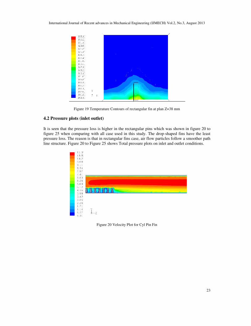
Figure 19 Temperature Contours of rectangular fin at plan Z=38 mm
4.2 Pressure plots (inlet outlet)
It is seen that the pressure loss is higher in the rectangular pins which was shown in figure 20 to
figure 25 when comparing with all case used in this study. The drop-shaped fins have the least
pressure loss. The reason is that in rectangular fins case, air flow particles follow a smoother path
line structure. Figure 20 to Figure 25 shows Total pressure plots on inlet and outlet conditions.
Figure 20 Velocity Plot for Cyl Pin Fin

International Journal of Recent advances in Mechanical Engineering (IJMECH) Vol.2, No.3, August 2013
24
Figure 21 Velocity Plot for Drop Pin Fin
Figure 22 Velocity Plot for Rect Pin Fin
Figure 23 Total Pressure Plot for Cyl Pin Fin

International Journal of Recent advances in Mechanical Engineering (IJMECH) Vol.2, No.3, August 2013
25
Figure 24 Total Pressure Plot for Drop Shaped Pin Fin
Figure 25 Total Pressure Plot for Rect Pin Fin

International Journal of Recent advances in Mechanical Engineering (IJMECH) Vol.2, No.3, August 2013
26
4.3 Velocity plots
Velocity plots are very helpful to understand air flow analysis in fins. It should be noted here that
the H/D ratio for drop-shaped pin-fins is smaller than the other ones (but wetted surface area is
equal for all). This behaviour can be reasoned by noticing the figure 26 to 28. It can be seen that
for Drop-shaped pin-fins, flow is accelerated in pin-fin section which could cause more friction
and pressure drop in fins top section
Figure 26 Temperature plot on VP-12 for all type Fins
Figure 27 Temperature plot on VP-22 for all type Fins

International Journal of Recent advances in Mechanical Engineering (IJMECH) Vol.2, No.3, August 2013
27
Figure 28 Temperature plot on VP-13 for All type Fins
3. CONCLUSIONS
A reasonable comparison of various pin-fin geometries has been attempted. A three-dimensional
conjugate problem has been studied with a three –dimensional CFD model .These were greatly
simplified by assuming 1-column in-line pin-fins with axes perpendicular to the flow and
isothermal heat transfer surfaces. At lower values of pressure drop and pumping power, drop
shaped fins work best. At higher values, drop-shaped fins and Circular fins offer highest
performance. For high Reynolds numbers, the fins thermal efficiency and effectiveness show
same behaviour, but drop-shaped fins configuration always stand a little bit upper. Also its
variation in different flow regimes is smoother, which means that the engine performance varies
according the working load conditions.
In last it was important to show that CFD tool is good approach to analysis thermal behaviour of
any thermal device. For future work refinement of mesh was good approach to refine results and
validation of CFD results will give more benefit to users.
REFERENCES
[1] S.R Mcilwain, “Improved prediction methods for finned tube bundle heat exchangers in cross flow”,
PhD Thesis, University of Strathclyde, Glasgow, 2003
[2] S.R Mcilwain, “A comparison of heat transfer around a single serrated finned tube and a plane finned
tube”, IJJRS, pp 88-94, 2010
[3] C. Weierman, “Pressure drop data for heavy duty finned tubes”, Chemical engineering progress, 73,
pp 69-72, 1977
[4] C. Weierman, “Correlations ease the selection of finned tubes”, The Oil and Gas Journal, Vol.74, pp
94-100, 1976
[5] V. Ganapathy, “Design and evaluate finned tube bundles”, Hydrocarbon processing, Vol.75, No.9,
pp103-111, 1996
[6] Poulikakos, A. and Bejan, A., “Fin Geometry for Minimum Entropy Generation in Forced
Convection” ASME Journal of Heat Transfer, Vol 104, pp. 616-623.

International Journal of Recent advances in Mechanical Engineering (IJMECH) Vol.2, No.3, August 2013
[7] Incropera F. P., DeWitt D. P., 1996, “Fundamentals of heat and m
Wiley & Sons, Pg. No. : 147-172.
[8] P. K. Nag, 2006, “Heat & Mass Transfer”, 2nd Edition, Tata McGraw Hill Co. Pg. No. : 86
425-449
[9] J. P. Holman, 2004, “Heat Transfer”, 9th Edition, Tata McGraw Hill Co,” Pg. No.
[10] Yunus A. Çengel, 2004, “Heat Transfer
Hill Co., Pg. No. : 156-168, 333
[11] H.Y. Pak, K. Park, and M.S. Choi, “Numerical Analysis of the Flow and Heat Transfer
Characteristics for Forced Convection
KSME Int. J., Vol. 12 no. 2, 1998, pp. 310~319.
[12] X.Liu, and M.K. Jensen, “Geometry Effects on Turbulent Flow and Heat Transfer in Internally
Finned Tubes,” ASME J. of Heat Transfer, Vol.123, 2001, pp. 1035~1044.
[13] G. Fabbri, “Heat Transfer Optimization in Internally Finned Tubes Under Laminar Flow Conditions,
Int. J. of Heat and Mass Transfer, Vol.41, No.10, 1998, pp.1243
[14] J. Lee, J, S. Lee, and K. Park, , Flow/Heat Transfer Analysis and Shape Optimization of a Heat
Exchanger with Internally Finned Tube, Trans, of the KSME (B), Vol.29, No.4, 2005, pp.1620
[15] Sanghwan Lee ,Juhee Lee, Kyoungwoo Park, An Application of Multi
Technique For Internally Finned Tube, Korean Journal of Air
Engineering, Vol 17, No. 10, 2005, pp. 938
[16] A.C.Poloni, A. Giurgevich, L Onesti, and V.Pediroda, Hybridisation of a Multi
Algorithm, a Neural Network and a Classical Optimizer for a Complex Design Problem in Fluid
Dynamics, Dipartimento diEnergetica Universita di Trieste, Italy, 1999.
Authors
Sanjay Kumar Sharma completed M.tech. (The
working as Assistant Professor, Gyan Vihar University, Jaipur.His area of interest is
thermal efficiency improvement of heat exchangers, CFD use in Solar applications,
Building energy simulation
E-mail address: [email protected]
Vikas Sharma completed M.tech. (Energy Engineering) MNIT, Jaipur and working
as Assistant Professor, Gyan Vihar University, Jaipur.His area of interest is use of
CFD in buildings, solar thermal devices and building energy simulation
E-mail ID: [email protected]
ecent advances in Mechanical Engineering (IJMECH) Vol.2, No.3, August 2013
Incropera F. P., DeWitt D. P., 1996, “Fundamentals of heat and mass transfer”, 4th Edition, John
172.
P. K. Nag, 2006, “Heat & Mass Transfer”, 2nd Edition, Tata McGraw Hill Co. Pg. No. : 86
J. P. Holman, 2004, “Heat Transfer”, 9th Edition, Tata McGraw Hill Co,” Pg. No. 43-53 & 315
Yunus A. Çengel, 2004, “Heat Transfer- A Practical Approach”, SI units 2nd Edition, Tata McGraw
168, 333-352 & 459-500
H.Y. Pak, K. Park, and M.S. Choi, “Numerical Analysis of the Flow and Heat Transfer
aracteristics for Forced Convection-Radiation in Entrance Region of an Internally Finned Tubes,”
KSME Int. J., Vol. 12 no. 2, 1998, pp. 310~319.
X.Liu, and M.K. Jensen, “Geometry Effects on Turbulent Flow and Heat Transfer in Internally
ASME J. of Heat Transfer, Vol.123, 2001, pp. 1035~1044.
G. Fabbri, “Heat Transfer Optimization in Internally Finned Tubes Under Laminar Flow Conditions,
Int. J. of Heat and Mass Transfer, Vol.41, No.10, 1998, pp.1243-1253.
K. Park, , Flow/Heat Transfer Analysis and Shape Optimization of a Heat
Exchanger with Internally Finned Tube, Trans, of the KSME (B), Vol.29, No.4, 2005, pp.1620
Sanghwan Lee ,Juhee Lee, Kyoungwoo Park, An Application of Multi-Objective Global
Technique For Internally Finned Tube, Korean Journal of Air- Conditioning and Refrigeration
Engineering, Vol 17, No. 10, 2005, pp. 938-946.
A.C.Poloni, A. Giurgevich, L Onesti, and V.Pediroda, Hybridisation of a Multi-Objective Genetic
lgorithm, a Neural Network and a Classical Optimizer for a Complex Design Problem in Fluid
Dynamics, Dipartimento diEnergetica Universita di Trieste, Italy, 1999.
completed M.tech. (Thermal Engineering) RTU, Kota and
working as Assistant Professor, Gyan Vihar University, Jaipur.His area of interest is
thermal efficiency improvement of heat exchangers, CFD use in Solar applications,
completed M.tech. (Energy Engineering) MNIT, Jaipur and working
as Assistant Professor, Gyan Vihar University, Jaipur.His area of interest is use of
in buildings, solar thermal devices and building energy simulation.
ecent advances in Mechanical Engineering (IJMECH) Vol.2, No.3, August 2013
28
ass transfer”, 4th Edition, John
P. K. Nag, 2006, “Heat & Mass Transfer”, 2nd Edition, Tata McGraw Hill Co. Pg. No. : 86- 108 &
53 & 315-350
A Practical Approach”, SI units 2nd Edition, Tata McGraw
H.Y. Pak, K. Park, and M.S. Choi, “Numerical Analysis of the Flow and Heat Transfer
Radiation in Entrance Region of an Internally Finned Tubes,”
X.Liu, and M.K. Jensen, “Geometry Effects on Turbulent Flow and Heat Transfer in Internally
G. Fabbri, “Heat Transfer Optimization in Internally Finned Tubes Under Laminar Flow Conditions,
K. Park, , Flow/Heat Transfer Analysis and Shape Optimization of a Heat
Exchanger with Internally Finned Tube, Trans, of the KSME (B), Vol.29, No.4, 2005, pp.1620-1629.
Objective Global Optimization
Conditioning and Refrigeration
Objective Genetic
lgorithm, a Neural Network and a Classical Optimizer for a Complex Design Problem in Fluid