maxepro version 2 manual - · pdf fileowner’s manual pool products ... to avoid stress...
TRANSCRIPT

1
Should the installer or owner be unfamiliarwith the correct installation or operation ofthis type of equipment you should contact
the distributor/manufacturer for thecorrect advice before proceeding with the
installation or operation of the product.
An earth leakage or residualcurrent protection device must be fitted to
all installations.
OW
NE
R’S
MA
NU
AL
Pool Products
MAX-E-PROTM
POOL PUMP
MaxEPro_OwnersManual_2012
Monday, 17 December 2012 10:03:44 AM
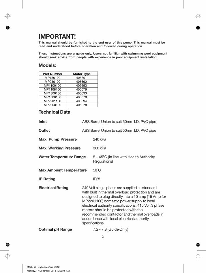
IMPORTANT!This manual should be furnished to the end user of this pump. This manual must beread and understood before operation and followed during operation.
These instructions are a guide only. Users not familiar with swimming pool equipmentshould seek advice from people with experience in pool equipment installation.
Models:
Technical Data
Inlet ABS Barrel Union to suit 50mm I.D. PVC pipe
Outlet ABS Barrel Union to suit 50mm I.D. PVC pipe
Max. Pump Pressure 240 kPa
Max. Working Pressure 360 kPa
Water Temperature Range 5 – 450C (In line with Health AuthorityRegulations)
Max Ambient Temperature 500C
IP Rating IP25
Electrical Rating 240 Volt single phase are supplied as standardwith built in thermal overload protection and aredesigned to plug directly into a 10 amp (15 Amp forMP2201100) domestic power supply to localelectrical authority specifications. 415 Volt 3 phasemotors should be protected with therecommended contactor and thermal overloads inaccordance with local electrical authorityspecifications.
Optimal pH Range 7.2 - 7.8 (Guide Only)
Motor Type 405691405692 405692 405076 405693 405078 405694 405078
Part Number MP730100 MP930100
MP1100100 MP1108100 MP1500100 MP1508100 MP2201100 MP2208100
2
MaxEPro_OwnersManual_2012
Monday, 17 December 2012 10:03:45 AM

Installation
Incorrectly installed or testedequipment may fail, causing severeinjury or property damage.
Read and follow instructions in owner’s manual wheninstalling and operating equipment. Have a trained poolprofessional perform all pressure tests.
1. Do not connect system to a high pressure or citywater system.
2. Use equipment only in a pool or spa installation.3. Install pump with at least 2 hydraulically balanced
main drains equipped with correctly installed,screw-fastened, anti-entrapment certified coversaccording to local regulations.
3. Trapped air in system can cause explosion. Ensureall air is out of system before operating or testingequipment.
Before pressure testing, make the following safety checks:• Check all clamps, bolts, lids, and system accessories prior to testing.• Release all air in system before testing.• Tighten trap lid to 4.1 kg-m torque for testing.• Water pressure for test must be less than 172kPa (25 PSI).• Water temperature for test must be less than 35°C.• Limit test to 24 hours. After test, visually check system to be sure it
is ready for operation. Remove trap lid and retighten hand tight only.
Pressure Testing(Have a trained pool professional perform all pressure tests.)
Fire and burn hazard. Modern motors run at high tempera-tures. To reduce risk of fire, do not allow leaves, debris, orforeign matter to collect around the pump motor. To avoidburns when handling the motor, let it cool for at least 20minutes before trying to work on it. A thermal overload switchprotects the motor from heat damage during operation.
3
MaxEPro_OwnersManual_2012
Monday, 17 December 2012 10:03:45 AM

ClampKnob
Discharge Portto filter or pool Strainer Basket
cover
Suction PortFrom poolor vacuumFilters
Equipotential Bonding Lug
Pump may be bolted to levelfoundation or mounting bracketFigure 1
Installation (Continued)
Only qualified, licensed personnel should install pump and wiringwhilst observing local safety regulations.Pump mount must:Be located away from corrosive or flammable chemicals.Have enough ventilation to maintain air temperature at less than themaximum ambient temperature rating. If this pump is installed in anenclosure/pump house, the enclosure must have adequate ventilationand air circulation to keep the temperature in the enclosure at or belowthe motor’s rated ambient temperature whenever the pump is running.Be solid - Level - Rigid - Vibration free. (To reduce vibration and pipe stress,bolt pump to mount).Allow pump suction inlet height to be as close to water level as possible.Allow use of short, direct suction pipe (to reduce friction losses).Allow for shut-off valves in suction and discharge piping.Have adequate floor drainage to prevent flooding.Be protected from excess moisture.Allow adequate access for servicing pump and piping.
Pentair recommends mounting the pump on a concrete platform for quietestperformance.
NOTICE: For three-phase motor pumps, start the motor for a few revolutionschecking that rotation direction is clockwise (watch the motor from the fanside). If rotation is counter-clockwise, change over the connections of twophases.
4
MaxEPro_OwnersManual_2012
Monday, 17 December 2012 10:03:45 AM

Teflon Taping Instructions:Use only new or clean PVC pipe fittings.Wrap male pipe threads with one to two layers (or a sufficient number oflayers) of Teflon tape. Cover entire threaded portion.Do not overtighten or tighten past thread stop in pump port.If leaks occur, remove pipe, clean off old tape, rewrap as previously with oneto two additional layers of tape and remake the connection.NOTICE: Support all piping connected with pump.
Piping:Use at least 2” (50mm) PVC pipe. Increase size if a long run is needed.To avoid stress on the pump, support both suction and discharge pipesindependently. Place these supports as close to the pump as possible.To avoid a strain left by a gap at the last connection, start all piping at thepump and run pipe away from the pump.Never use a suction pipe smaller than pump suction connection (2”/50mm).To avoid airlocking, slope suction pipe slightly upward toward the pump.NOTICE: To prevent flooding when removing pump for service, all floodedsuction systems must have shut-off valves in suction and discharge pipes.
Fittings:Fittings restrict flow; for best efficiency use fewest possible fittings.Avoid fittings which could cause an air trap.Pool outlets:Use only non-entrapping suction fitting or double suction conforming with theAS1926.3-2003 Standard.
Installation (Continued)
NOTICE: If the pump is not provided with a supply cord and a plug, or withother means of disconnection from the supply having a contact separation ofat least 3mm in all poles, such means for disconnection must be incorporatedin the fixed wiring.
NOTICE: Use Teflon tape for making all threaded connections to the pump.Do not use pipe dope (glue) as this will cause stress fractures in the pump.
NOTICE: Pump suction and discharge connections have moulded in threadstops. DO NOT screw pipe in beyond these stops.
5
MaxEPro_OwnersManual_2012
Monday, 17 December 2012 10:03:45 AM

Pool Pump Suction Requirements
Pump suction is hazardous and can trap and drown or disembowelbathers. Do not use or operate swimming pools, spas, or hot tubs ifa suction outlet cover is missing, broken, or loose. Follow the guidelinesbelow for a pump installation which minimises risk to users of pools, spas, andhot tubs.
Entrapment ProtectionThe pump suction system must provide protection against the hazard ofsuction entrapment or hair entrapment/entanglement.
Suction Outlet CoversAll suction outlet covers must be maintained. They must be replaced ifcracked, broken, or missing.See below for outlet cover certification requirements.All suction outlets must have correctly installed, screw-fastened covers inplace.
Testing and CertificationSuction outlet covers must have been tested by a nationally recognisedtesting laboratory and found to comply with the latest AS1926.3-2010Standard or ASME/ANSI Specification for Suction Fittings For Use in Swim-ming Pools, Spas, Hot Tubs, and Whirlpool Bathtub Applications.
6
MaxEPro_OwnersManual_2012
Monday, 17 December 2012 10:03:45 AM

Electrical
VoltageVoltage at motor must not be more than 10% above or below motor nameplate rated voltage or motor may overheat, causing overload tripping and reduced component life. If voltage is less than 90% or more than 110% of rated voltage when motor is running at full load, consult power company.
Ground motor before connecting to electrical power supply. Failure to ground motor can cause severe or fatal electrical shock hazard.
Do not ground to a gas supply line.
To avoid dangerous or fatal electrical shock, turn OFF power to motor before working on electrical connections.
Residual Current Device (RCD) tripping indicates an electrical problem. If RCD trips and will not reset, have a qualified electrician inspect and repair electrical system.
Exactly match supply voltage to motor nameplate voltage. Incorrect voltage can cause fire or seriously damage motor and voids warranty. If in doubt consult a licensed electrician.
The pump is to be supplied by an isolating transformer or supplied through a residual current device (RCD) having a rated residual operating current not exceeding 30 mA.
If the supply cord is damaged, it must be replaced by the manufacturer, its service agent or similarly qualifiedpersons in order to avoid a hazard. Warranty is void if unauthorised modifications are made to any component.
The MaxEPro series of pool pumps is classified as "Double Insulated to Water Circuit". Please refer to the Electical Wiring Rules (AS/NZS 3000) and local statutes and regulations as to whether equipotential bonding is necessary. Pentair Water Australia recommends equipotential bonding for additional safety.
7
MaxEPro_OwnersManual_2012
Monday, 17 December 2012 10:03:45 AM

Operation
NEVER run pump dry. Running pump dry maydamage seals, causing leakage and flooding. Fillpump with water before starting motor.
Before removing trap cover:1. SWITCH OFF POWER SUPPLY to pump and
unplug from outlet before proceeding.2. CLOSE SHUT-OFF VALVES in suction and
discharge pipes.3. RELEASE ALL PRESSURE from pump and
piping system.4. NEVER tighten or loosen clamp while pump
is operating!
If pump is being pressure tested, ensure pressurehas been released before removing trap cover.
Do not block pump suction. To do so with body,may cause severe or fatal injury. Small childrenusing pool must ALWAYS have close adultsupervision.
This appliance is not intended for use by persons (including children) with reduced physical, sensory or mental capabilities, or lack of experience and knowledge, unless they have been given supervision or instruction concerning use of the appliance by a person responsible for their safety.
Children should be supervised to ensure they do not play with the appliance.
Fire and burn hazard. Modern motors run at high temperatures. To reduce the risk of fire, do not allow leaves, debris, or foreign matter to collect around the pump motor. To avoid burns when handling the motor, let it cool for at least 20 minutes before trying to work on it. An internal thermal overload switch protects the motor from heat damage during operation.
NOTICE: Maximum ambient temperature for motor operation must not exceed maximum ambient tempearture rating.
8
MaxEPro_OwnersManual_2012
Monday, 17 December 2012 10:03:45 AM

Priming PumpRelease all air from filter, pump and piping system: refer filter owner’s manual.In a flooded suction system (water source higher than pump), pump will primeitself when suction and discharge valves are opened.If pump is not in a flooded suction system, disconnect power supply to pumpand remove trap cover handle ring and trap cover; fill trap and pump withwater.Do not lubricate the trap cover O’ring. The original equipment O’ring containsa permanent internal lubricant.
NOTICE: If you replace the O’ring with a non-internally lubricated O’ring, youmay need to apply a silicone based lubricant.
Clean and inspect O’ring; reinstall on trap.Replace trap cover and handle ring on trap; turn handle ring clockwise totighten cover.
NOTICE: Tighten trap cover handle ring by hand only (no wrenches!)
Pump should prime now. Priming time will depend on vertical height of suctionlift and horizontal length of suction piping. The self-priming time range is 1 to 5minutes for a height difference of 2 to 3 metres, under normal installationconditions. Normal conditions are understood to be: with suction having aninternal diameter of DN 50mm, water temperature at 20oC, and 50Hz mainspower supply.Should the pump not prime, ensure that all valves are open, lint trap is clear ofdebris and suction pipe end is submersed in water, and that there are no leaksin suction pipe.See Troubleshooting Guide.
Operation (Continued)
9
MaxEPro_OwnersManual_2012
Monday, 17 December 2012 10:03:45 AM
Operation (Continued)
Routine MaintenanceThe only routine maintenance required is inspection/cleaning of trap basket.Debris or trash that collects in basket will choke off water flow through thepump. Follow instructions below to clean trap:
1. Switch off power to pump, close valves in suction and discharge, andrelease all pressure from system before proceeding.
2. Remove trap cover handle ring (turn counterclockwise). If necessary,tap handles gently with a rubber mallet.
3. Remove strainer basket and clean. Ensure all holes in basket are clear,flush basket with water and replace in trap with large opening at pipeconnection port (between ribs provided). If basket is replacedbackwards cover will not fit on trap body. To clean transparent cover,use water and neutral soap only. Do not use solvents.
4. Clean and inspect lid o’ring; reinstall on trap.5. Clean O’ring groove on trap body and replace cover and handle ring. To
help keep cover from sticking, tighten hand tight only.6. Prime pump (refer priming instructions).
Pump Service
Pump should only be serviced by qualified personnel. For bestresults, use only genuine Pentair factory parts. Be sure to prime pump before starting.
Before removing clamp or trap cover:1. SWITCH OFF POWER to pump before proceeding.2. CLOSE SHUT-OFF VALVES in suction and discharge pipes.3. RELEASE ALL PRESSURE from pump and piping system.4. NEVER tighten or loosen clamp while pump is operating!
To avoid dangerous or fatal electrical shock hazard, turn OFF power to motorand remove plug from power outlet before working on pump or motor.
No lubrication or regular maintenance is needed beyond reasonable care andperiodic cleaning of strainer basket. When pump is not in use and there is a riskof frost, empty it completely through the drain plug.If shaft seal is worn or damaged, repair as per the procedure on page 11.
10
MaxEPro_OwnersManual_2012
Monday, 17 December 2012 10:03:45 AM
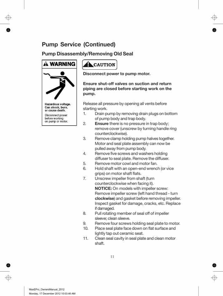
Pump Service (Continued)
Pump Disassembly/Removing Old Seal
Disconnect power to pump motor.
Ensure shut-off valves on suction and returnpiping are closed before starting work on thepump.
Release all pressure by opening all vents beforestarting work.1. Drain pump by removing drain plugs on bottom
of pump body and trap body.2. Ensure there is no pressure in trap body;
remove cover (unscrew by turning handle ringcounterclockwise).
3. Remove clamp holding pump halves together.Motor and seal plate assembly can now bepulled away from pump body.
4. Remove five screws and washers holdingdiffuser to seal plate. Remove the diffuser.
5. Remove motor cowl and motor fan.6. Hold shaft with an open-end wrench (or vice
grips) on motor shaft flats.7. Unscrew impeller from shaft (turn
counterclockwise when facing it).NOTICE: On models with impeller screw:Remove impeller screw (left hand thread - turnclockwise) and gasket before removing impeller.Inspect gasket for damage, cracks, etc. Replaceif damaged.
8. Pull rotating member of seal off of impellersleeve; clean sleeve.
9. Remove four screws holding seal plate to motor.10. Place seal plate face down on flat surface and
lightly tap out ceramic seat.11. Clean seal cavity in seal plate and clean motor
shaft.
11
MaxEPro_OwnersManual_2012
Monday, 17 December 2012 10:03:46 AM

Pump Service (Continued)Pump Reassembly/Installing NewSeal1. Ceramic seat must be clean and free of
dirt, grease, dust, etc. Wet outer edgeof rubber cup on ceramic seat withsmall amount of liquid detergent; pressceramic seat into seal plate firmly andsquarely with finger pressure (as perfigure to left).
2. If ceramic seat will not locate properly,remove it, place face up on bench andreclean cavity. Repeat Step 1. Ceramicseat should now locate.
3. If seat still will not locate properly, placea cardboard washer over the polishedface and use a piece of ¾” (19mm)standard pipe for pressing purposes.NOTICE: Be sure not to scratch ormar the polished surface or the seal willleak.
4. Remount seal plate on motor. Tighten bolts to 69-92 kg/cm torque.5. Apply a small amount of liquid detergent to inside diameter of rotating
half of seal.6. Slide rotating seal member, polished face last, over impeller sleeve until
rubber drive ring hits shoulder.NOTICE: Be sure not to nick or scratch polished seal face; seal willleak if face is damaged.
7. Screw impeller onto shaft (clockwise); this will automatically locate sealin seal plate.NOTICE: On models with impeller screw: Install impeller gasket and lockscrew (left-hand thread - turn counterclockwise to tighten). Torquelock screw to 57.6-63 kg/cm.
8. Mount diffuser on seal plate; tighten screws to 11.2-16.1 kg/cm torque.9. Assemble motor and seal plate to pump casing; ensuring that the body
clamp is properly seated.NOTICE: Clamp knob can be located in any position around the pumpbody; if it is moved after assembly, tighten knob while tapping aroundthe clamp to assist sealing. Do not move clamp while pump is full ofwater.
10. Prime pump according to instructions on Page 9.
Hazardous pressure. Release all pressure from pump and piping system before working on pump or attempting to adjust or remove clamp. Clamp may blow off of pump if adjusted under pressure.
12
MaxEPro_OwnersManual_2012
Monday, 17 December 2012 10:03:46 AM

Troubleshooting Guide
Symptom Cause Remedy Pump must be primed; make sure that the pump casing and strainer are full of water. Refer priming instructions. Make sure there are no leaks in suction piping. Make sure suction pipe inlet is well below the water level to prevent pump from sucking air.
Suction leaks / lost prime
Suction lift of 3 to 6 metres will reduce performance. Suction lift of more than 6 metres will prevent pumping and cause pump to lose prime. In either instance, move the pump closer (vertically) to water source. Ensure that the suction pipe diameter is large enough. Ensure trap is not clogged with debris; if it is, clean strainer & basket. Make sure that the impeller is not clogged. This should be checked by qualified personnel only. Impeller and diffuser may be worn. If so, check with your local Pentair dealer or suitably qualified personnel.
Clogged pipe / strainer / impeller, worn impeller.
Pump may be trying to push too high a column of water. If so, a “higher head” pump is required.
No power at outlet. Use another electrical appliance that is known to work to check the power outlet.
Blown fuse. Check fuse and replace if necessary.
Motor burnt out due to voltage spike or flooded by water.
The motor may need replacing.
Pump failure or reduced capacity or reduced discharge pressure.
Valves turned to the closed position.
Check the plumbing to ensure the valves are in the correct position for pumping on the suction and discharge.
13
MaxEPro_OwnersManual_2012
Monday, 17 December 2012 10:03:46 AM

Troubleshooting Guide (Continued)
Symptom Cause Remedy Air ingress to system. Prime the pump. Check that
there are no air leaks in the suction piping or fittings. Ensure the strainer lid is airtight and fitted securely. Check that there are no leaks coming from beneath the pump.
Low voltage. Check voltage at motor terminals and at meter while pump is running – this check should be performed by a qualified electrician only. If voltage is low check for loose connections or consult your power company.
Pump running too slowly.
Pump may be too hot. Check line voltage; if less than 90% or more than 110% of rated voltage consult a licensed electrician. Increase ventilation. Reduce ambient temperature. Tighten any loose connections.
Pump leaking from between the casing and motor.
Casing bolts are not tightened sufficiently; Casing O’ring is worn; Mechanical seal requires replacing; Casing clamp is loose.
Switch off the power to the pump. Loosen the casing bolts. Check the alignment and condition of the casing o’ring before retightening the bolts. Replace the o’ring if leaking persists. Replace the mechanical seal.
Should problems persist, contact your nearest Pentair service agent.
14
MaxEPro_OwnersManual_2012
Monday, 17 December 2012 10:03:46 AM

15
MaxEPro_OwnersManual_2012
Monday, 17 December 2012 10:03:46 AM

Part No. MP730100 MP930100 MP1100100 MP1108100 MP1500100 MP1508100 MP2200100 MP2208100Description 730W - 1P 930W - 1P 1100W - 1P 1100W - 3P 1500W - 1P 1500W - 3P 2200W - 1P 2200W - 3P
Qty405691 405692 405692 405076 405693 405078 405694 405078801418 801419 801419 801366 801420 800565 801482 800565
1 C35-44 C35-44 C35-44 C35-44 C35-44 C35-44 C35-44 C35-441
4 702594 702594 702594 702594 702594 702594 702594 702594
4 703107 703107 703107 703107 703107 703107 703107 7031071 C103-194PSSG C103-194PSSG C103-194PSSG C103-194PSSG C103-194PSSG C103-194PSSG C103-194PSSG C103-194PSSG1 U9-228A U9-228A U9-228A U9-228A U9-228A U9-228A U9-228A U9-228A1 801428 801428 801428 801428 801428 801428 801428 8014281 C19-37A C19-37A C19-37A C19-37A C19-37A C19-37A C19-37A C19-37A1 C105-238PPB C105-238PRB C105-238PSB C105-238PSB C105-238PLBAB C105-238PLBAB C105-238PHAB C105-238PHAB1111551 801273 801273 801273 801273 801274 801274 801274 8012741 17307-0110W 17307-0110W 17307-0110W 17307-0110W 17307-0110W 17307-0110W 17307-0110W 17307-0110W111 801275 801275 801275 801275 801275 801275 801275 8012751 C8 -58P C8 -58P C8 -58P C8 -58P C8 -58P C8 -58P C8 -58P C8 -58P2 800405 800405 800405 800405 800405 800405 800405 8004052 SRU30-918SS SRU30-918SS SRU30-918SS SRU30-918SS SRU30-918SS SRU30-918SS SRU30-918SS SRU30-918SS1 801276 801276 801276 801276 801276 801276 801276 8012762222 801245 801245 801245 801245 801245 801245 801245 801245
1
Part Number
2 MOTOR PAD
3 WATER SLINGER
4 SCREW 3/8in x 1in HEX ST/ST
5 WASHER 3/8in x 3/4in ST/ST
6 SEAL PLATE
7 O-RING BODY
8 SEAL 3/4"
9 CLAMP
10 IMPELLER (INCLUDES 11&12)
11 IMPELLER SCREW (3 PHASE ONLY)
12 O-RING IMPELLER SCREW (3 PHASE ONLY)
13 DIFFUSER
14 O-RING DIFFUSER
15 LOCKWASHER - DIFFUSER
SCREW - DIFFUSER
DIFFUSER KIT (INCLUDES 13,14,15 & 16)
TANK BODY ASSEMBLY
TANK AND TRAP LID
O-RING TANK AND TRAP LID
TANK LID AND O-RING (INCLUDES 19&20)
BASKET
DRAIN PLUG AND O-RING
SCREW BASE
BASE WITH MOTOR PAD AND SCREWS
ORING - COLLAR UNION
COLLAR UNION SLIP 2"
COLLAR UNION 2"
UNION KIT (INCLUDES 26, 27&28 x2)
MOTOR1
Item Description Item Description
Item
16
17
18
19
20
21
22
23
24
25
26
27
28
29
1
2
3
4
5
6
7
8
9
10
11
12
13
14
15
16
17
18
19
20
21
22
23
24
25
26
27
28
29
16
MaxEPro_OwnersManual_2012
Monday, 17 December 2012 10:03:46 AM
NOTES:
MaxEPro_OwnersManual_2012
Monday, 17 December 2012 10:03:46 AM

NOTES:
MaxEPro_OwnersManual_2012
Monday, 17 December 2012 10:03:46 AM

NOTES:
MaxEPro_OwnersManual_2012
Monday, 17 December 2012 10:03:46 AM

L300
215
121
2
18
IMPORTANT
Please attach your sales invoice/docket here as proof of purchase should warranty service be required.
Please do not return Warranty Form to Pentair Australia - please retain for your records.
Purchased From ...................................................................................................................
Purchase Date..................................... Serial No.............................. Model No........................
© Information contained here-in remains the property of Pentair Water Pty Ltd. Any reproduction, display, publication, modif ication or distribution is strictly prohibited without the prior written
permission of Pentair Water Pty Ltd.
Disclaimer: Every endeavour has been made to publish the correct details in this data sheet. No responsibility will be taken for errors, omissions or changes in product specif ications.
Pentair Water reserves the right to change specif ications
Head Office
Pentair AU/NZ: 1-21 Monash Drive, Dandenong South, Vic 3175
Australia
National Customer Service: Phone: 1300 137 344 Fax: 1800 006 688 National Dealer Locator: Phone: 1800 664 266
Ema il: [email protected] We b: www.pentair.com.au
New Zealand
National Customer Service: Phone: 0800 654 112 Fax: 0800 806 642 National Dealer Locator: Phone: 0800 664 269
Ema il: [email protected] Web: www.pentair.co.nz
International Australia/New Zealand Phone: +61 3 9709 5800 Fax: +61 3 9709 5888
MaxEPro_OwnersManual_2012
Monday, 17 December 2012 10:03:46 AM