maxcheck 400 oct15 - cewe instrument · standards standards is13779, is14697, iec62052-11,...
TRANSCRIPT

Maxchek 400
Applications
Ÿ Commercial and industrial sanctioned demand monitoring & controlling applications
Ÿ Control panels for complete plant demand controllingŸ Demand management for commerce and industry
Maxchek 400 is a smart maximum demand controller with
standard size 96x96 mm specifically designed for industries to
keep a check on their maximum demand. It gives an alarm when
demand approaches a preset value and also switches off non-
essential loads in a pre-programmed logical sequence. This
predictive maximum demand controller (MDC) allows stage wise
load restoration to maximize the use of a sanctioned load.
Maxchek 400 is most suitable for the demand control of
industrial consumers, HT consumers and commercial
establishments.
Ÿ Two modes of programming - Preventive Mode (only Alarm no control), Predictive Mode (Alarm and automatic control)
Ÿ Predictive demand control to forewarn, take corrective measures and check maximum demand crossovers
Ÿ Multi-level (phase wise and shift wise) priority based automatic load control mechanism to disconnect low priority loads in phased manner
Ÿ Configurable demand integration period for sliding and fixed type
Ÿ Optimised load disconnection timeŸ Online load planning by continuously indicating loads that
can be added or need to be disconnected (within safe operating limits)
Ÿ Check meter with accuracy class 0.2s,0.5s and 1.0Ÿ Auto and push button displayŸ An user friendly software to program and monitorŸ Control Outputs for alarm and trip applications - it provides 3
control and one alarm outputs, in the form of potential free contacts
Ÿ Large four-line seven-digit display (9.7 H x 5 W mm) with quadrant identification section and bar graph for instantaneous power-level indication
Features
Maximum Demand Controller
Benefits
Ÿ Easy interface with external devices through built-in Modbus (RS-485)
Ÿ Detachable connectors for easy installationŸ Three relay and one alarm outputŸ Suitable for star or delta connections and for low or high-
voltage applicationsŸ Alarm output for audible indication.Ÿ Field-configurable CT / PT primary and secondary values
using push-buttonsŸ Calibration LED for on-site accuracy checkŸ Configurable software (ConfigView) for reading of parameters
and load surveyŸ Shift wise demand configuration

Maxchek 400
Enriched Software - ConfigView
Shift wise demand configuration on trip circuits
Tripping Priority configuration oftrip circuits in shifts
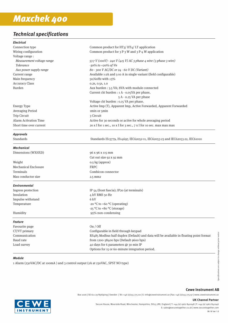
Mechanical Dimensions
Maxchek 400
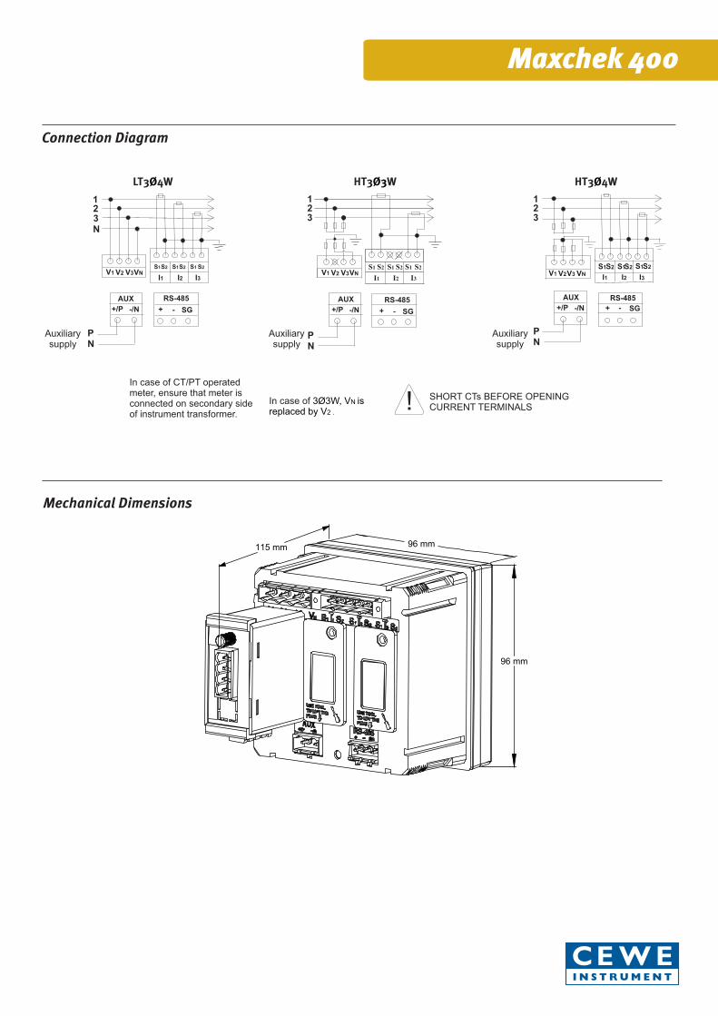
Connection Diagram
In case of CT/PT operated meter, ensure that meter is connected on secondary sideof instrument transformer.
In case of 3Ø3W, VN is replaced by V2 .
LT3 4WØ
SHORT CTs BEFORE OPENINGCURRENT TERMINALS !
123N
V1I1 I2 I3
V2 V3VNS1 S1S2 S1S2 S2
AUX
+/P -/N
PN
RS-485
+ SG-
Auxiliarysupply
HT3 WØ3123
V1I1 I2 I3
V2 V3VNS1 S1 S2 S1S2 S2
AUX
+/P -/N
PN
RS-485
+ - SG
Auxiliarysupply
HT3 4WØ123
V1V2 VNV3I1 I2 I3
S1 S1 S1S2S2 S2
AUX
+/P -/N
RS-485
+ SG-
PN
Auxiliarysupply
Electrical Connection type Common product for HT3/ HT4/ LT applicationWiring configuration Common product for 3 P-3 W and 3 P-4 W applicationVoltage range : Measurement voltage range 57.7 V (100V) - 240 V (415 V) AC 3 phase 4 wire (3 phase 3 wire) Tolerance -30% to +20% of Vn Aux power supply range 80 - 300 V AC/DC or 24 - 60 V DC (Variant)Current range Available 1-2A and 5-10 A in single variant (field configurable)Main frequency 50/60Hz with ±5%Accuracy Class 0.2s, 0.5s, 1.0Burden Aux burden : 3.5 VA; 8VA with module connected Current ckt burden : 1 A - 0.05VA per phase, 5 A - 0.25 VA per phase Voltage ckt burden : 0.15 VA per phase.Energy Type Active Imp (T), Apparent Imp, Active Forwarded, Apparent ForwardedAveraging Period 1min or 5minTrip Circuit 3 CircuitAlarm Activation Time Active for 30 seconds or active for whole averaging periodShort time over current 20 x I for 1 sec., 10 x I for 3 sec., 7 x I for 10 sec. max max max
Approvals Standards Standards IS13779, IS14697, IEC62052-11, IEC62053-23 and IEC62053-22, IEC61010
Mechanical Dimensions (WXHXD) 96 x 96 x 115 mm Cut out size 92 x 92 mmWeight 0.5 kg (approx)Mechanical Enclosure FRPCTerminals Combicon connectorMax conductor size 2.5 mm2
Environmental Ingress protection IP 54 (front fascia); IP20 (at terminals)Insulation 4 kV RMS 50 HzImpulse withstand 6 kVTemperature -20 °C to +60 °C (operating) -25 °C to +80 °C (storage)Humidity 95% non-condensing
Feature Favourite page On / OffCT/VT primary Configurable in field through keypadCommunication RS485 Modbus half duplex (Default) and data will be available in floating point formatBaud rate from 1200-38400 bps (Default 9600 bps)Load survey 40 days for 6 parameters @ 30 min IP Options for 15 or 60-minute integration period.
Module 1 Alarm (230VAC/DC at 100mA ) and 3 control output (2A at 230VAC, SPST NO type)
Technical specifications
Spec
ific
atio
ns a
re s
ubje
ct to
cha
nge
wit
hout
pri
or n
otic
e
Maxchek 400
Box 1006 | SE-611 29 Nyköping | Sweden | Tel: +46 (0)155 775 00 | E: [email protected] |Fax: +46 (0)155 775 97 | www.ceweinstrument.se
Cewe Instrument AB
Secure House, Moorside Road, Winchester, Hampshire, SO23 7RX, England | T: +44 (o) 1962 840048 | F: +44 (o) 1962 841046 E: [email protected] | www.securetogether.com
UK Channel Partner
06-16 Ver 1.0