max force eges450
DESCRIPTION
Service manual for engine,TRANSCRIPT

SE
RV
ICE
MA
NU
AL
SERVICE MANUAL
MaxxForce® DT, 9 and 10 Diesel Engines
Model Year 2010 and Up
EGES-450-1
MaxxF
orce
® DT
, 9 and
10 D
IES
EL
EN
GIN
ES
EG
ES
-450-1
Mo
del Y
ear 2010 and
Up
© 2012 Navistar, Inc. All rights reserved
Printed in the United States of America

SERVICE MANUAL
ENGINE SERVICE MANUAL
EGES-450-1
2012
EGES-450-1Read all safety instructions in the "Safety Information" section of this Manual before doing any procedures.
Follow all warnings, cautions, and notes.©2012 Navistar, Inc. All rights reserved. All marks are trademarks of their respective owners.

ENGINE SERVICE MANUAL I
Table of Contents
Foreword.. . . . . . . . . . . . . . . . . . . . . . . . . . . . . . . . . . . . . . . . . . . . . . . . . . . . . . . . . . . . . . . . . . . . . . . . . . . . . . . . . . . . . . . . . . . . . . . . . . . . . . . . . . . . . . . . . .1
Service Diagnosis. . . . . . . . . . . . . . . . . . . . . . . . . . . . . . . . . . . . . . . . . . . . . . . . . . . . . . . . . . . . . . . . . . . . . . . . . . . . . . . . . . . . . . . . . . . . . . . . . . . . . . . .2
Safety Information. . . . . . . . . . . . . . . . . . . . . . . . . . . . . . . . . . . . . . . . . . . . . . . . . . . . . . . . . . . . . . . . . . . . . . . . . . . . . . . . . . . . . . . . . . . . . . . . . . . . . . . .3
Engine Systems.. . . . . . . . . . . . . . . . . . . . . . . . . . . . . . . . . . . . . . . . . . . . . . . . . . . . . . . . . . . . . . . . . . . . . . . . . . . . . . . . . . . . . . . . . . . . . . . . . . . . . . . . . .5
Mounting Engine on Engine Stand. . . . . . . . . . . . . . . . . . . . . . . . . . . . . . . . . . . . . . . . . . . . . . . . . . . . . . . . . . . . . . . . . . . . . . . . . . . . . . . . . . .59
Engine Electrical. . . . . . . . . . . . . . . . . . . . . . . . . . . . . . . . . . . . . . . . . . . . . . . . . . . . . . . . . . . . . . . . . . . . . . . . . . . . . . . . . . . . . . . . . . . . . . . . . . . . . . . . .71
Down Stream Injection (DSI) & Related Components. . . . . . . . . . . . . . . . . . . . . . . . . . . . . . . . . . . . . . . . . . . . . . . . . . . . . . . . . . .111
Dual Stage Turbocharger and Exhaust Brake. . . . . . . . . . . . . . . . . . . . . . . . . . . . . . . . . . . . . . . . . . . . . . . . . . . . . . . . . . . . . . . . . . . .125
Exhaust Gas Recirculation (EGR) System.. . . . . . . . . . . . . . . . . . . . . . . . . . . . . . . . . . . . . . . . . . . . . . . . . . . . . . . . . . . . . . . . . . . . . . . .151
Intake, Inlet, and Exhaust Manifolds. . . . . . . . . . . . . . . . . . . . . . . . . . . . . . . . . . . . . . . . . . . . . . . . . . . . . . . . . . . . . . . . . . . . . . . . . . . . . . . .171
Fuel and High-pressure Oil Systems. . . . . . . . . . . . . . . . . . . . . . . . . . . . . . . . . . . . . . . . . . . . . . . . . . . . . . . . . . . . . . . . . . . . . . . . . . . . . . .185
Engine Brake. . . . . . . . . . . . . . . . . . . . . . . . . . . . . . . . . . . . . . . . . . . . . . . . . . . . . . . . . . . . . . . . . . . . . . . . . . . . . . . . . . . . . . . . . . . . . . . . . . . . . . . . . . .217
Air Compressor and Power Steering Pump.. . . . . . . . . . . . . . . . . . . . . . . . . . . . . . . . . . . . . . . . . . . . . . . . . . . . . . . . . . . . . . . . . . . . . .235
Oil System Module Assembly. . . . . . . . . . . . . . . . . . . . . . . . . . . . . . . . . . . . . . . . . . . . . . . . . . . . . . . . . . . . . . . . . . . . . . . . . . . . . . . . . . . . . . . 247
Oil Pan and Oil Suction Tube. . . . . . . . . . . . . . . . . . . . . . . . . . . . . . . . . . . . . . . . . . . . . . . . . . . . . . . . . . . . . . . . . . . . . . . . . . . . . . . . . . . . . . . .265
Front Cover, Cooling System, and Related Components. . . . . . . . . . . . . . . . . . . . . . . . . . . . . . . . . . . . . . . . . . . . . . . . . . . . . . .277
Cylinder Head and Valve Train. . . . . . . . . . . . . . . . . . . . . . . . . . . . . . . . . . . . . . . . . . . . . . . . . . . . . . . . . . . . . . . . . . . . . . . . . . . . . . . . . . . . . . .329
Flywheel and Flywheel Housing.. . . . . . . . . . . . . . . . . . . . . . . . . . . . . . . . . . . . . . . . . . . . . . . . . . . . . . . . . . . . . . . . . . . . . . . . . . . . . . . . . . . .377
Power Cylinders. . . . . . . . . . . . . . . . . . . . . . . . . . . . . . . . . . . . . . . . . . . . . . . . . . . . . . . . . . . . . . . . . . . . . . . . . . . . . . . . . . . . . . . . . . . . . . . . . . . . . . . .405
Crankcase, Crankshaft, and Camshaft. . . . . . . . . . . . . . . . . . . . . . . . . . . . . . . . . . . . . . . . . . . . . . . . . . . . . . . . . . . . . . . . . . . . . . . . . . . . .443
Abbreviations and Acronyms.. . . . . . . . . . . . . . . . . . . . . . . . . . . . . . . . . . . . . . . . . . . . . . . . . . . . . . . . . . . . . . . . . . . . . . . . . . . . . . . . . . . . . . .483
Terminology.. . . . . . . . . . . . . . . . . . . . . . . . . . . . . . . . . . . . . . . . . . . . . . . . . . . . . . . . . . . . . . . . . . . . . . . . . . . . . . . . . . . . . . . . . . . . . . . . . . . . . . . . . . . .489
Appendix A – Specifications. . . . . . . . . . . . . . . . . . . . . . . . . . . . . . . . . . . . . . . . . . . . . . . . . . . . . . . . . . . . . . . . . . . . . . . . . . . . . . . . . . . . . . . . .501
EGES-450-1Read all safety instructions in the "Safety Information" section of this Manual before doing any procedures.
Follow all warnings, cautions, and notes.©2012 Navistar, Inc. All rights reserved. All marks are trademarks of their respective owners.

II ENGINE SERVICE MANUAL
Appendix B – Torques. . . . . . . . . . . . . . . . . . . . . . . . . . . . . . . . . . . . . . . . . . . . . . . . . . . . . . . . . . . . . . . . . . . . . . . . . . . . . . . . . . . . . . . . . . . . . . . . .519
Appendix C – Special Service Tools. . . . . . . . . . . . . . . . . . . . . . . . . . . . . . . . . . . . . . . . . . . . . . . . . . . . . . . . . . . . . . . . . . . . . . . . . . . . . . . .531
EGES-450-1Read all safety instructions in the "Safety Information" section of this Manual before doing any procedures.
Follow all warnings, cautions, and notes.©2012 Navistar, Inc. All rights reserved. All marks are trademarks of their respective owners.

ENGINE SERVICE MANUAL 1
ForewordNavistar, Inc. is committed to continuous researchand development to improve products and introducetechnological advances. Procedures, specifications,and parts defined in published technical serviceliterature may be altered.
This Engine Service Manual provides a generalsequence of procedures for out-of-chassis engineoverhaul (removal, inspection, and installation). Forin-chassis service of parts and assemblies, thesequence may vary.
NOTE: Photo illustrations identify specific parts orassemblies that support text and procedures; otherareas in a photo illustration may not be exact.
See vehicle manuals and Technical ServiceInformation (TSI) bulletins for additional information.
Technical Service Literature
1171999R1 MaxxForce® DT, 9, and 10 EngineOperation and MaintenanceManual
EGES-450 MaxxForce® DT, 9, and 10 EngineService Manual
EGES-455 MaxxForce® DT, 9, and 10 EngineDiagnostic Manual
EGED-460 MaxxForce® Diagnostic Form
EGED-495 MaxxForce® Electronic ControlSystems Form
Technical Service Literature is revised periodicallyand mailed automatically to “Revision Service”subscribers. If a technical publication is ordered, thelatest revision will be supplied.
NOTE: To order technical service literature, contactyour International® dealer.
All marks are trademarks of their respective owners.
EGES-450-1Read all safety instructions in the "Safety Information" section of this Manual before doing any procedures.
Follow all warnings, cautions, and notes.©2012 Navistar, Inc. All rights reserved. All marks are trademarks of their respective owners.

2 ENGINE SERVICE MANUAL
Service DiagnosisService diagnosis is an investigative procedure thatmust be followed to find and correct an engineapplication problem or an engine problem.
If the problem is engine application, see specificvehicle manuals for further diagnostic information.
If the problem is the engine, see specific EngineDiagnostic Manual for further diagnostic information.
Prerequisites for Effective Diagnosis
• Availability of gauges, diagnostic test equipment,and diagnostic software.
• Availability of current information for engineapplication and engine systems.
• Knowledge of the principles of operation forengine application and engine systems.
• Knowledge to understand and do procedures indiagnostic and service publications.
Technical Service Literature required for EffectiveDiagnosis
• Engine Service Manual
• Engine Diagnostic Manual
• Diagnostics Forms
• Electronic Control Systems Diagnostics Forms
• Service Bulletins
EGES-450-1Read all safety instructions in the "Safety Information" section of this Manual before doing any procedures.
Follow all warnings, cautions, and notes.©2012 Navistar, Inc. All rights reserved. All marks are trademarks of their respective owners.

ENGINE SERVICE MANUAL 3
Safety Information
This manual provides general and specificmaintenance procedures essential for reliable engineoperation and your safety. Since many variations inprocedures, tools, and service parts are involved,advice for all possible safety conditions and hazardscannot be stated.
Read safety instructions before doing any service andtest procedures for the engine or vehicle. See relatedapplication manuals for more information.
Obey Safety Instructions, Warnings, Cautions, andNotes in this manual. Not following warnings,cautions, and notes can lead to injury, death ordamage to the engine or vehicle.
Safety Terminology
Three terms are used to stress your safety and safeoperation of the engine: Warning, Caution, and Note
Warning: A warning describes actions necessary toprevent or eliminate conditions, hazards, and unsafepractices that can cause personal injury or death.
Caution: A caution describes actions necessaryto prevent or eliminate conditions that can causedamage to the engine or vehicle.
Note: A note describes actions necessary for correct,efficient engine operation.
Safety Instructions
Work Area
• Keep work area clean, dry, and organized.
• Keep tools and parts off the floor.
• Make sure the work area is ventilated and well lit.
• Make sure a First Aid Kit is available.
Safety Equipment
• Use correct lifting devices.
• Use safety blocks and stands.
Protective Measures
• Wear protective safety glasses and shoes.
• Wear correct hearing protection.
• Wear cotton work clothing.
• Wear sleeved heat protective gloves.
• Do not wear rings, watches or other jewelry.
• Restrain long hair.
Vehicle
• Shift transmission to park or neutral, set parkingbrake, and block wheels before doing diagnosticor service procedures.
• Clear the area before starting the engine.
Engine
• The engine should be operated or serviced onlyby qualified individuals.
• Provide necessary ventilation when operatingengine in a closed area.
• Keep combustible material away from engineexhaust system and exhaust manifolds.
• Install all shields, guards, and access coversbefore operating engine.
• Do not run engine with unprotected air inlets orexhaust openings. If unavoidable for servicereasons, put protective screens over all openingsbefore servicing engine.
• Shut engine off and relieve all pressure in thesystem before removing panels, housing covers,and caps.
• If an engine is not safe to operate, tag the engineand ignition key.
Fire Prevention
• Make sure charged fire extinguishers are in thework area.
NOTE: Check the classification of each fireextinguisher to ensure that the following fire typescan be extinguished.
1. Type A — Wood, paper, textiles, and rubbish
2. Type B — Flammable liquids
3. Type C — Electrical equipment
Batteries
• Always disconnect the main negative batterycable first.
• Always connect the main negative battery cablelast.
• Avoid leaning over batteries.
EGES-450-1Read all safety instructions in the "Safety Information" section of this Manual before doing any procedures.
Follow all warnings, cautions, and notes.©2012 Navistar, Inc. All rights reserved. All marks are trademarks of their respective owners.

4 ENGINE SERVICE MANUAL
• Protect your eyes.
• Do not expose batteries to flames or sparks.
• Do not smoke in workplace.
Compressed Air
• Use an OSHA approved blow gun rated at 207kPa (30 psi).
• Limit air pressure to 207 kPa (30 psi).
• Wear safety glasses or goggles.
• Wear hearing protection.
• Use shielding to protect others in the work area.
• Do not direct compressed air at body or clothing.
Tools
• Make sure all tools are in good condition.
• Make sure all standard electrical tools aregrounded.
• Check for frayed or damaged power cords beforeusing power tools.
Fluids Under Pressure
• Use extreme caution when working on systemsunder pressure.
• Follow approved procedures only.
Fuel
• Do not over fill the fuel tank. Over fill creates a firehazard.
• Do not smoke in the work area.
• Do not refuel the tank when the engine is running.
Removal of Tools, Parts, and Equipment
• Reinstall all safety guards, shields, and coversafter servicing the engine.
• Make sure all tools, parts, and service equipmentare removed from the engine and vehicle after allwork is done.
EGES-450-1Read all safety instructions in the "Safety Information" section of this Manual before doing any procedures.
Follow all warnings, cautions, and notes.©2012 Navistar, Inc. All rights reserved. All marks are trademarks of their respective owners.

ENGINE SYSTEMS 5
Table of Contents
Engine Identification. . . . . . . . . . . . . . . . . . . . . . . . . . . . . . . . . . . . . . . . . . . . . . . . . . . . . . . . . . . . . . . . . . . . . . . . . . . . . . . . . . . . . . . . . . . . . . . . . . . . .7Engine Serial Number. . . . . . . . . . . . . . . . . . . . . . . . . . . . . . . . . . . . . . . . . . . . . . . . . . . . . . . . . . . . . . . . . . . . . . . . . . . . . . . . . . . . . . . . . .7Engine Emission Label. . . . . . . . . . . . . . . . . . . . . . . . . . . . . . . . . . . . . . . . . . . . . . . . . . . . . . . . . . . . . . . . . . . . . . . . . . . . . . . . . . . . . . . . .7Engine Accessory Labels. . . . . . . . . . . . . . . . . . . . . . . . . . . . . . . . . . . . . . . . . . . . . . . . . . . . . . . . . . . . . . . . . . . . . . . . . . . . . . . . . . . . . .7Engine Description. . . . . . . . . . . . . . . . . . . . . . . . . . . . . . . . . . . . . . . . . . . . . . . . . . . . . . . . . . . . . . . . . . . . . . . . . . . . . . . . . . . . . . . . . . . . . .8
Standard Features. . . . . . . . . . . . . . . . . . . . . . . . . . . . . . . . . . . . . . . . . . . . . . . . . . . . . . . . . . . . . . . . . . . . . . . . . . . . . . . . . . . . .9Optional Features. . . . . . . . . . . . . . . . . . . . . . . . . . . . . . . . . . . . . . . . . . . . . . . . . . . . . . . . . . . . . . . . . . . . . . . . . . . . . . . . . . . .10Chassis Mounted Features. . . . . . . . . . . . . . . . . . . . . . . . . . . . . . . . . . . . . . . . . . . . . . . . . . . . . . . . . . . . . . . . . . . . . . . . .10
Engine Component Locations (245 hp and above). . . . . . . . . . . . . . . . . . . . . . . . . . . . . . . . . . . . . . . . . . . . . . . . . . . . . .11
Air Management System (AMS). . . . . . . . . . . . . . . . . . . . . . . . . . . . . . . . . . . . . . . . . . . . . . . . . . . . . . . . . . . . . . . . . . . . . . . . . . . . . . . . . . . . . . .16Air Flow – Pre Combustion. . . . . . . . . . . . . . . . . . . . . . . . . . . . . . . . . . . . . . . . . . . . . . . . . . . . . . . . . . . . . . . . . . . . . . . . . . . . . . . . . . .17Air Flow – Post Combustion. . . . . . . . . . . . . . . . . . . . . . . . . . . . . . . . . . . . . . . . . . . . . . . . . . . . . . . . . . . . . . . . . . . . . . . . . . . . . . . . .17Air Management Components. . . . . . . . . . . . . . . . . . . . . . . . . . . . . . . . . . . . . . . . . . . . . . . . . . . . . . . . . . . . . . . . . . . . . . . . . . . . . . .17
Turbochargers. . . . . . . . . . . . . . . . . . . . . . . . . . . . . . . . . . . . . . . . . . . . . . . . . . . . . . . . . . . . . . . . . . . . . . . . . . . . . . . . . . . . . . . .17Interstage Cooler (ISC). . . . . . . . . . . . . . . . . . . . . . . . . . . . . . . . . . . . . . . . . . . . . . . . . . . . . . . . . . . . . . . . . . . . . . . . . . . . . .18High-pressure Charge Air Cooler (HPCAC). . . . . . . . . . . . . . . . . . . . . . . . . . . . . . . . . . . . . . . . . . . . . . . . . . . . . .19Turbocharger 2 Wastegate Control (TC2WC) Valve. . . . . . . . . . . . . . . . . . . . . . . . . . . . . . . . . . . . . . . . . . . .19Exhaust Gas Recirculation (EGR) System.. . . . . . . . . . . . . . . . . . . . . . . . . . . . . . . . . . . . . . . . . . . . . . . . . . . . . .20Crankcase Ventilation System.. . . . . . . . . . . . . . . . . . . . . . . . . . . . . . . . . . . . . . . . . . . . . . . . . . . . . . . . . . . . . . . . . . . .22
Aftertreatment (AFT) System.. . . . . . . . . . . . . . . . . . . . . . . . . . . . . . . . . . . . . . . . . . . . . . . . . . . . . . . . . . . . . . . . . . . . . . . . . . . . . . .23
Fuel Management System.. . . . . . . . . . . . . . . . . . . . . . . . . . . . . . . . . . . . . . . . . . . . . . . . . . . . . . . . . . . . . . . . . . . . . . . . . . . . . . . . . . . . . . . . . . . .26ICP System.. . . . . . . . . . . . . . . . . . . . . . . . . . . . . . . . . . . . . . . . . . . . . . . . . . . . . . . . . . . . . . . . . . . . . . . . . . . . . . . . . . . . . . . . . . . . . . . . . . . . .27
High-Pressure Oil Flow.. . . . . . . . . . . . . . . . . . . . . . . . . . . . . . . . . . . . . . . . . . . . . . . . . . . . . . . . . . . . . . . . . . . . . . . . . . . . .28ICP Closed Loop System.. . . . . . . . . . . . . . . . . . . . . . . . . . . . . . . . . . . . . . . . . . . . . . . . . . . . . . . . . . . . . . . . . . . . . . . . . .28ICP Control System.. . . . . . . . . . . . . . . . . . . . . . . . . . . . . . . . . . . . . . . . . . . . . . . . . . . . . . . . . . . . . . . . . . . . . . . . . . . . . . . . .29Fuel Injector. . . . . . . . . . . . . . . . . . . . . . . . . . . . . . . . . . . . . . . . . . . . . . . . . . . . . . . . . . . . . . . . . . . . . . . . . . . . . . . . . . . . . . . . . . .30
Fuel Supply System.. . . . . . . . . . . . . . . . . . . . . . . . . . . . . . . . . . . . . . . . . . . . . . . . . . . . . . . . . . . . . . . . . . . . . . . . . . . . . . . . . . . . . . . . . . . . . . . . . . . .32Fuel Supply System Flow.. . . . . . . . . . . . . . . . . . . . . . . . . . . . . . . . . . . . . . . .. . . . . . . . . . . . . . . . . . . . . . . . . . . . . . . . . . . . . . . . . . .33
Engine Lubrication System.. . . . . . . . . . . . . . . . . . . . . . . . . . . . . . . . . . . . . . . . . . . . . . . . . . . . . . . . . . . . . . . . . . . . . . . . . . . . . . . . . . . . . . . . . . .36Oil Flow.. . . . . . . . . . . . . . . . . . . . . . . . . . . . . . . . . . . . . . . . . . . . . . . . . . . . . . . . . . . . . . . . . . . . . . . . . . . . . . . . . . . . . . . . . . . . . . . . . . . . . . . . .37
Engine Cooling System.. . . . . . . . . . . . . . . . . . . . . . . . . . . . . . . . . . . . . . . . . . . . . . . . . . . . . . . . . . . . . . . . . . . . . . . . . . . . . . . . . . . . . . . . . . . . . . .39Cooling System Description. . . . . . . . . . . . . . . . . . . . . . . . . . . . . . . . . . . . . . . . . . . . . . . . . . . . . . . . . . . . . . . . . . . . . . . . . . . . . . . . .39Cooling System Components. . . . . . . . . . . . . . . . . . . . . . . . . . . . . . . . . . . . . . . . . . . . . . . . . . . . . . . . . . . . . . . . . . . . . . . . . . . . . . .40
Coolant Heater (optional). . . . . . . . . . . . . . . . . . . . . . . . . . . . . . . . . . . . . . . . . . . . . . . . . . . . . . . . . . . . . . . . . . . . . . . . . . .40Thermostat Operation. . . . . . . . . . . . . . . . . . . . . . . . . . . . . . . . . . . . . . . . . . . . . . . . . . . . . . . . . . . . . . . . . . . . . . . . . . . . . . .40Low Temperature Radiator (LTR) Thermostat Operation. . . . . . . . . . . . . . . . . . . . . . . . . . . . . . . . . . . . . .42
Electronic Control System.. . . . . . . . . . . . . . . . . . . . . . . . . . . . . . . . . . . . . . . . . . . . . . . . . . . . . . . . . . . . . . . . . . . . . . . . . . . . . . . . . . . . . . . . . . . .43Electronic Control System Components. . . . . . . . . . . . . . . . . . . . . . . . . . . . . . . . . . . . . . . . . . . . . . . . . . . . . . . . . . . . . . . . . .43
Operation and Function. . . . . . . . . . . . . . . . . . . . . . . . . . . . . . . . . . . . . . . . . . . . . . . . . . . . . . . . . . . . . . . . . . . . . . . . . . . . .44Reference Voltage (VREF). . . . . . . . . . . . . . . . . . . . . . . . . . . . . . . . . . . . . . . . . . . . . . . . . . . . . . . . . . . . . . . . . . . . . . . . . .44
EGES-450-1Read all safety instructions in the "Safety Information" section of this Manual before doing any procedures.
Follow all warnings, cautions, and notes.©2012 Navistar, Inc. All rights reserved. All marks are trademarks of their respective owners.

6 ENGINE SYSTEMS
Microprocessor. . . . . . . . . . . . . . . . . . . . . . . . . . . . . . . . . . . . . . . . . . . . . . . . . . . . . . . . . . . . . . . . . . . . . . . . . . . . . . . . . . . . . . .44Actuator Control. . . . . . . . . . . . . . . . . . . . . . . . . . . . . . . . . . . . . . . . . . . . . . . . . . . . . . . . . . . . . . . . . . . . . . . . . . . . . . . . . . . . . .44
Actuators. . . . . . . . . . . . . . . . . . . . . . . . . . . . . . . . . . . . . . . . . . . . . . . . . . . . . . . . . . . . . . . . . . . . . . . . . . . . . . . . . . . . . . . . . . . . . . . . . . . . . . . .44Exhaust Gas Recirculation (EGR) Valve. . . . . . . . . . . . . . . . . . . . . . . . . . . . . . . . . . . . . . . . . . . . . . . . . . . . . . . . . .44Intake Air Heater (IAH) Relay. . . . . . . . . . . . . . . . . . . . . . . . . . . . . . . . . . . . . . . . . . . . . . . . . . . . . . . . . . . . . . . . . . . . . . .44Engine Throttle Valve (ETV) and Position Sensor. . . . . . . . . . . . . . . . . . . . . . . . . . . . . . . . . . . . . . . . . . . . . .44Turbocharger 2 Wastegate Control (TC2WC) valve (turbocharger wastegate actuator). . .45Exhaust Back Pressure Valve (EBPV). . . . . . . . . . . . . . . . . . . . . . . . . . . . . . . . . . . . . . . . . . . . . . . . . . . . . . . . . . . .45Engine Compression Brake (ECB) valve. . . . . . . . . . . . . . . . . . . . . . . . . . . . . . . . . . . . . . . . . . . . . . . . . . . . . . . . .45Injection Pressure Regulator (IPR) valve. . . . . . . . . . . . . . . . . . . . . . . . . . . . . . . . . . . . . . . . . . . . . . . . . . . . . . . .45
Engine and Vehicle Sensors. . . . . . . . . . . . . . . . . . . . . . . . . . . . . . . . . . . . . . . . . . . . . . . . . . . . . . . . . . . . . . . . . . . . . . . . . . . . . . . . .46Temperature Sensors. . . . . . . . . . . . . . . . . . . . . . . . . . . . . . . . . . . . . . . . . . . . . . . . . . . . . . . . . . . . . . . . . . . . . . . . . . . . . . . .46Variable Capacitance Sensors. . . . . . . . . . . . . . . . . . . . . . . . . . . . . . . . . . . . . . . . . . . . . . . . . . . . . . . . . . . . . . . . . . . . .47Magnetic Pickup Sensors. . . . . . . . . . . . . . . . . . . . . . . . . . . . . . . . . . . . . . . . . . . . . . . . . . . . . . . . . . . . . . . . . . . . . . . . . . .48High-pressure Sensors. . . . . . . . . . . . . . . . . . . . . . . . . . . . . . . . . . . . . . . . . . . . . . . . . . . . . . . . . . . . . . . . . . . . . . . . . . . . . .49Potentiometer. . . . . . . . . . . . . . . . . . . . . . . . . . . . . . . . . . . . . . . . . . . . . . . . . . . . . . . . . . . . . . . . . . . . . . . . . . . . . . . . . . . . . . . . .50Switches. . . . . . . . . . . . . . . . . . . . . . . . . . . . . . . . . . . . . . . . . . . . . . . . . . . . . . . . . . . . . . . . . . . . . . . . . . . . . . . . . . . . . . . . . . . . . . .51
Engine Throttle Valve Control System.. . . . . . . . . . . . . . . . . . . . . . . . . . . . . . . . . . . . . . . . . . . . . . . . . . . . . . . . . . . . . . . . . . . .52
Exhaust and Engine Brake System.. . . . . . . . . . . . . . . . . . . . . . . . . . . . . . . . . . . . . . . . . . . . . . . . . . . . . . . . . . . . . . . . . . . . . . . . . . . . . . . . .53Exhaust Brake. . . . . . . . . . . . . . . . . . . . . . . . . . . . . . . . . . . . . . . . . . . . . . . . . . . . . . . . . . . . . . . . . . . . . . . . . . . . . . . . . . . . . . . . . . . . . . . . . .53Engine Brake. . . . . . . . . . . . . . . . . . . . . . . . . . . . . . . . . . . . . . . . . . . . . . . . . . . . . . . . . . . . . . . . . . . . . . . . . . . . . . . . . . . . . . . . . . . . . . . . . . .54
Operation. . . . . . . . . . . . . . . . . . . . . . . . . . . . . . . . . . . . . . . . . . . . . . . . . . . . . . . . . . . . . . . . . . . . . . . . . . . . . . . . . . . . . . . . . . . . . .55Operation Modes. . . . . . . . . . . . . . . . . . . . . . . . . . . . . . . . . . . . . . . . . . . . . . . . . . . . . . . . . . . . . . . . . . . . . . . . . . . . . . . . . . . . .56
EGES-450-1Read all safety instructions in the "Safety Information" section of this Manual before doing any procedures.
Follow all warnings, cautions, and notes.©2012 Navistar, Inc. All rights reserved. All marks are trademarks of their respective owners.

ENGINE SYSTEMS 7
Engine IdentificationEngine Serial Number
Figure 1 Engine serial number
The engine serial number is in two locations:
• Stamped on the right side of the crankcase, justabove the oil filter header
• On the engine emission label on the valve cover
Engine Serial Number Examples
MaxxForce® DT: 466HM2UXXXXXXX
MaxxForce® 9 and 10: 570HM2UXXXXXXX
Engine Serial Number Codes
466 – Engine displacement570 – Engine displacementH – Diesel, turbocharged, Charge Air Cooler (CAC)and electronically controlledM2 – Motor truckU – United States7 digit suffix – Engine serial number sequencebeginning with 3300001
Engine Emission Label
Figure 2 U.S. Environmental Protection Agency(EPA) exhaust emission label (example)
The U.S. Environmental Protection Agency (EPA)exhaust emission label is attached on top of the valvecover. The EPA label typically includes the following:
• Model year
• Engine family, model, and displacement
• Advertised brake horsepower and torque rating
• Emission family and control systems
• Valve lash specifications
• Engine serial number
• EPA, EURO, and reserved fields for specificapplications
Engine Accessory Labels
The following engine accessories may havemanufacturer’s labels or identification plates:
• Air compressor
• Air conditioning compressor
• Alternator
EGES-450-1Read all safety instructions in the "Safety Information" section of this Manual before doing any procedures.
Follow all warnings, cautions, and notes.©2012 Navistar, Inc. All rights reserved. All marks are trademarks of their respective owners.

8 ENGINE SYSTEMS
• Cooling fan clutch
• Power steering pump
• Starter motor
Engine Description
MaxxForce® DT, 9, and 10 Diesel Engines
Engine configuration 4 stroke, inline six cylinder diesel
MaxxForce® DT displacement 7.6 L (466 in3)
MaxxForce® 9 and 10 displacement 9.3 L (570 in3)
Bore (sleeve diameter) 116.6 mm (4.59 in)
Stroke
• MaxxForce® DT
• MaxxForce® 9 and 10
119 mm (4.68 in)
146 mm (5.75 in)
Compression ratio
• MaxxForce® DT
• MaxxForce® 9 and 10
16.9 : 1
16.5 : 1
Aspiration Dual turbocharged and charge air cooled
Advertised brake horsepower @ rpm See EPA exhaust emission label
Peak torque @ rpm See EPA exhaust emission label
Engine rotation (facing flywheel) Counterclockwise
Combustion system Direct injection turbocharged
Fuel system Electro-hydraulic injection
Total engine weight (oil and accessories)
• MaxxForce® DT
• MaxxForce® 9 and 10
824 kg (1816 lbs)
845 kg (1864 lbs)
Cooling system capacity (engine only) 12.8 L (13.5 qts US)
Lube system capacity (including filter) 28 L (30 qts US)
Lube system capacity (overhaul only, with filter) 32 L (34 qts US)
Firing order 1-5-3-6-2-4
EGES-450-1Read all safety instructions in the "Safety Information" section of this Manual before doing any procedures.
Follow all warnings, cautions, and notes.©2012 Navistar, Inc. All rights reserved. All marks are trademarks of their respective owners.
ENGINE SYSTEMS 9
Standard Features
MaxxForce® DT, 9, and 10 diesel engines aredesigned for increased durability, reliability, and easeof maintenance.
The cylinder head has four valves per cylinder withcentrally located fuel injectors directing fuel overthe pistons. This configuration provides improvedperformance and reduces emissions.
The camshaft is supported by four insert bushingspressed into the crankcase. The camshaft gear isdriven from the front of the engine. A thrust flangeis located between the camshaft and the drive gear.The overhead valve train includes mechanical rollerlifters, push rods, rocker arms, and dual valves thatopen using a valve bridge.
MaxxForce® DT engines use one-piece aluminumalloy pistons. MaxxForce® 9 and 10 engines useone-piece steel pistons. All pistons have zero pinoffset and centered combustion bowls; therefore,pistons can be installed safely without orientation:there is NO front-of-engine arrow or “CAMSIDE”marking on the piston crown to indicate a necessarypiston direction.
The one piece crankcase uses replaceable wetcylinder sleeves that are sealed by a single creviceseal ring. Some applications include a crankcaseladder which is designed to support heavier loadsand reduce engine noise.
The crankshaft has seven main bearings with foreand aft thrust controlled at the rear bearing. Onefractured cap connecting rod is attached at eachcrankshaft journal. A piston pin moves freely insidethe connecting rod and piston. Piston pin retainingrings secure the piston pin in the piston. The rear oilseal carrier is part of the flywheel housing.
A lube oil pump is mounted on the front cover and isdriven by the crankshaft. Pressurized oil is suppliedto engine components and the high-pressure injectionsystem. All MaxxForce® DT, 9, and 10 engines usean engine oil cooler and spin-on engine oil filter.
The coolant supply housing serves as the mountingbracket for the refrigerant compressor. Mountingcapabilities for a dual refrigerant compressor areavailable as an option. The pad mounting design ofthe alternator and refrigerant compressor bracketsprovide easy removal and improved durability.
The electric low-pressure fuel supply pump drawsfuel from the fuel tank through the fuel filter assembly.The assembly includes a strainer, filter, drain valve,Water in Fuel (WIF) sensor, and Fuel DeliveryPressure (FDP) sensor. If equipped, an optionalfuel heater element is installed in the fuel filterassembly. Conditioned fuel is pumped through theintake manifold and cylinder head to the fuel injectors.
The WIF sensor detects water in the fuel system.When water reaches the level of the sensor locatedin the fuel filter assembly, the instrument panel’samber FUEL FILTER lamp will illuminate. Thecollected water must be removed immediately. Wateris drained by opening the drain valve on the fuel filterassembly.
The fuel injection system is electro-hydraulic. Thesystem includes an under-valve-cover high-pressureoil manifold, fuel injectors, and a high-pressure oilpump. The injectors are installed in the cylinder head,under the high-pressure oil manifold.
MaxxForce® DT, 9, and 10 engines use dualturbochargers with an air-to-air High Pressure ChargeAir Cooler (HPCAC) after the second stage. Aninterstage cooler is used after the first stage forapplications with 245 hp and above.
The Inlet Air Heater (IAH) system warms the incomingair to aid cold engine starting and to reduce whitesmoke and engine noise. The IAH system will initiallyilluminate the WAIT TO START lamp located on theinstrument panel. When the lamp turns off, the enginecan be started.
The Exhaust Gas Recirculation (EGR) systemcirculates cooled exhaust into the intake air streamin the intake manifold. This cools the combustionprocess and reduces the formation of NOX engineemissions.
A closed crankcase breather system uses an enginemounted oil separator to return oil to the crankcaseand vent crankcase pressure into the intake system.
The Down Stream Injection (DSI) system aidesin controlling emissions by injecting fuel into theexhaust stream. The fuel causes an exothermicreaction which increases the temperature of theexhaust gas. This increase in temperature allows formore efficient conversion of soot into ash withinthe Diesel Particulate Filter (DPF). Along withDSI, the Diesel Oxidation Catalyst (DOC) aids increating the required exothermic reaction. DSI
EGES-450-1Read all safety instructions in the "Safety Information" section of this Manual before doing any procedures.
Follow all warnings, cautions, and notes.©2012 Navistar, Inc. All rights reserved. All marks are trademarks of their respective owners.
10 ENGINE SYSTEMS
consists of the Aftertreatment Control Module (ACM),Downstream Injection (DSI) assembly, hydrocarboninjector assembly, fuel lines, and coolant lines. TheElectronic Control Module (ECM) communicates withthe ACM to control the timing and quantity of fuelsprayed from the hydrocarbon injector assembly. TheECM signals the exhaust brake valve assembly tocontrol the position of the exhaust back pressurevalve to increase or decrease the exhaust gas backpressure and temperature to allow the DOC and DPFto function efficiently.
The exhaust back pressure valve acts asan aftertreatment device to manage exhausttemperature. The resulting rise in back pressure,increases exhaust temperature.
Optional Features
Optional features include the following:
• Air compressor
• Hydraulic pump
• Engine brake
• Exhaust brake
An air compressor is available for applications thatrequire air brakes or air suspension.
A hydraulic power steering pump can be used with orwithout the air compressor.
Engine brake and exhaust brake systems areavailable for applications that could benefit fromadded speed reduction capability.
Optional Cold Climate Features
Optional cold climate features include the following:
• Oil pan heater
• Coolant heater
• Fuel heater
All three heaters use an electric element to warmengine fluids in cold weather.
The oil pan heater warms engine oil to ensureoptimum oil flow.
The coolant heater warms engine coolant surroundingthe cylinders. Warmed engine coolant aids in coldengine start-up and performance.
The fuel heater is installed in the fuel filter assemblyand warms the supply fuel. Warmed supply fuelprevents waxing, and improves performance and fueleconomy during cold weather start-up.
Chassis Mounted Features
A Charge Air Cooler (CAC) is an air-to-air heatexchanger, which increases the density of the aircharge.
The Aftertreatment System, part of the larger exhaustsystem, processes engine exhaust to meet tailpipeemission requirements.
• The Pre-Diesel Oxidation Catalyst (PDOC) aids increating the required exothermic reaction beforethe exhaust gas enters the Diesel OxidationCatalyst (DOC).
• The Diesel Oxidation Catalyst (DOC) oxidizescarbon monoxide, hydrocarbons, and smallamounts of nitrogen oxide in the exhaust stream.
• The Diesel Particulate Filter (DPF) captures andoxidizes particulates in the exhaust stream andstores non-combustible ash.
EGES-450-1Read all safety instructions in the "Safety Information" section of this Manual before doing any procedures.
Follow all warnings, cautions, and notes.©2012 Navistar, Inc. All rights reserved. All marks are trademarks of their respective owners.

ENGINE SYSTEMS 11
Engine Component Locations (245 hp and above)
Figure 3 Component location – top
1. Alternator bracket2. High-pressure turbocharger
outlet3. Low-pressure turbocharger4. Exhaust back pressure valve5. Hydrocarbon injector assembly6. Exhaust brake valve assembly
7. Valve cover8. Intake Air Heater (IAH) relay
assembly9. Air and EGR mixer duct10. EGR valve11. Fuel filter cap
12. Interstage cooler (245 hp andabove)
13. Interstage cooler inlet elbow(245 hp and above)
14. Interstage cooler inlet duct (245hp and above)
EGES-450-1Read all safety instructions in the "Safety Information" section of this Manual before doing any procedures.
Follow all warnings, cautions, and notes.©2012 Navistar, Inc. All rights reserved. All marks are trademarks of their respective owners.

12 ENGINE SYSTEMS
Figure 4 Component location – front
1. Deaeration hose elbow2. Front cover3. Fan drive pulley4. Air compressor assembly5. Front engine mounting bracket
6. Vibration damper assembly7. Water inlet elbow8. Water pump pulley9. Automatic belt tensioner10. Turbo air inlet duct
11. High-pressure turbochargeroutlet
12. Water outlet tube assembly
EGES-450-1Read all safety instructions in the "Safety Information" section of this Manual before doing any procedures.
Follow all warnings, cautions, and notes.©2012 Navistar, Inc. All rights reserved. All marks are trademarks of their respective owners.

ENGINE SYSTEMS 13
Figure 5 Component location – exhaust side
1. Turbocharger heat shield2. Dual stage turbocharger
assembly3. Lifting eye4. Coolant supply housing
(refrigerant compressor mount)5. Coolant supply tube assembly
(high fin density EGR cooler)6. Breather outlet tube
7. Coolant return tube assembly(high fin density EGR cooler)
8. Breather inlet tube9. Crankcase breather assembly
with turbine10. Coolant return tube11. M16 plug assembly (coolant
drain under oil cooler module)12. Oil cooler module
13. Oil filter assembly14. Exhaust back pressure valve15. EGR cooler assembly16. Turbo oil supply tube assembly17. Exhaust brake valve assembly
EGES-450-1Read all safety instructions in the "Safety Information" section of this Manual before doing any procedures.
Follow all warnings, cautions, and notes.©2012 Navistar, Inc. All rights reserved. All marks are trademarks of their respective owners.

14 ENGINE SYSTEMS
Figure 6 Component location – intake side
1. Electric fuel pump2. Fuel filter cap3. Water drain valve assembly4. Exhaust Gas Recirculation
(EGR) valve5. Air and EGR mixer duct6. Downstream Injection (DSI)
assembly7. Lifting eye
8. Downstream Injection (DSI) feedtube assembly
9. Injection unit inlet tube assembly10. Intake manifold11. Engine Control Module (ECM)12. Coolant return hose (air
compressor)13. Power steering pump assembly14. Oil drain hose (air compressor)
15. Oil pan16. Air compressor assembly17. Oil supply hose (air compressor)18. Coolant supply hose (air
compressor)19. High pressure oil pump20. Fuel filter assembly with heater21. Electric fuel pump inlet
EGES-450-1Read all safety instructions in the "Safety Information" section of this Manual before doing any procedures.
Follow all warnings, cautions, and notes.©2012 Navistar, Inc. All rights reserved. All marks are trademarks of their respective owners.

ENGINE SYSTEMS 15
Figure 7 Component location – rear
1. Deaeration hose elbow2. Interstage cooler (245
horsepower and above)3. Valve cover4. Cylinder head assembly5. Injection unit inlet tube assembly
6. Exhaust brake valve to actuatorhose
7. Exhaust pipe assembly8. Rear engine mounting bracket
(2)9. Flywheel housing assembly
10. Flywheel11. EGR crossover duct12. Oil filler tube
EGES-450-1Read all safety instructions in the "Safety Information" section of this Manual before doing any procedures.
Follow all warnings, cautions, and notes.©2012 Navistar, Inc. All rights reserved. All marks are trademarks of their respective owners.

16 ENGINE SYSTEMS
Air Management System (AMS)
Figure 8 Air Management System (AMS)
The AMS includes the following:
• Air filter assembly
• Low-pressure turbocharger
• Interstage Cooler (ISC) (245 hp and above)
• High-pressure turbocharger
• High-pressure Charge Air Cooler (HPCAC)
• Engine Throttle Valve (ETV)
• Air and EGR mixer duct
• Exhaust and intake valves
• Exhaust Gas Recirculation (EGR) system
• Exhaust system
• Exhaust back pressure valve
• Exhaust – aftertreatment
EGES-450-1Read all safety instructions in the "Safety Information" section of this Manual before doing any procedures.
Follow all warnings, cautions, and notes.©2012 Navistar, Inc. All rights reserved. All marks are trademarks of their respective owners.

ENGINE SYSTEMS 17
Air Flow – Pre Combustion
Fresh air from the air filter enters the low-pressurecompressor where it is compressed and directedinto the ISC (245 hp and above ratings), if equipped.If not equipped with ISC, compressed air from thelow-pressure compressor is piped directly to thehigh-pressure compressor inlet. The high-pressureturbocharger further increases the intake air pressure.The hot compressed air flows into the HPCAC whereit is cooled, then through the Engine Throttle Valve(ETV) on the air and EGR mixer duct.
If the EGR valve is open, exhaust gas enters the highfin density EGR cooler from the rear of the exhaustmanifold and is transferred to the intake manifoldvia the EGR crossover duct. The exhaust gas thenpasses through a port in the intake manifold to theair and EGR mixer duct where it is mixed with filteredintake air. This mixture then flows through the intakemanifold and into the cylinder head.
If the EGR valve is closed, only filtered intake air flowsthrough the ETV, air and EGR mixer duct, and into theintake manifold.
Air Flow – Post Combustion
After combustion, gases exit through the cylinderhead exhaust valves and ports. Exhaust gas is forcedthrough the exhaust manifold where, dependingon the EGR valve position, it is split between theEGR system and the high-pressure turbocharger,
low-pressure turbocharger and the exhaust backpressure valve assembly.
The exhaust back pressure valve acts asan aftertreatment device to regulate exhausttemperatures.
Exhaust gases flow from the engine through thevehicle aftertreatment system to the exhaust tail pipe.
Air Management Components
Turbochargers
MaxxForce® DT, 9, and 10 engines are equipped withan electronically controlled two stage turbochargingsystem. This system provides high levels of charge airpressure to improve engine performance and to helpreduce emissions. Because of its ability to generatevery high charge air pressure levels, and to avoidCharge Air Cooler (CAC) overloading conditions, thesystem is fitted with a spring loaded turbochargerwastegate.
The turbocharger wastegate is actuated by chargeair pressure. The air pressure to the turbochargerwastegate actuator is controlled by the Turbocharger2 Wastegate Control (TC2WC) valve. The TC2WCvalve is controlled by Pulse Width Modulation (PWM)signals from the Electronic Control Module (ECM).
The high and low-pressure turbochargers are installedas an assembly on the exhaust manifold, on right sideof engine.
EGES-450-1Read all safety instructions in the "Safety Information" section of this Manual before doing any procedures.
Follow all warnings, cautions, and notes.©2012 Navistar, Inc. All rights reserved. All marks are trademarks of their respective owners.
18 ENGINE SYSTEMS
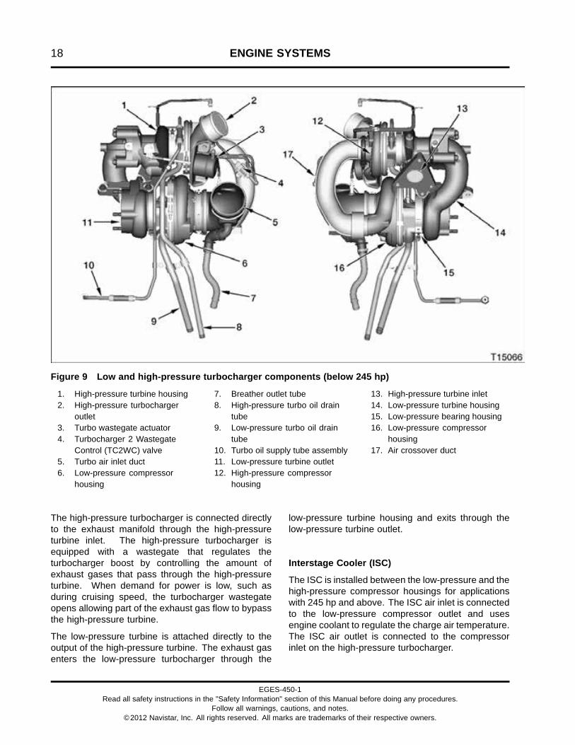
Figure 9 Low and high-pressure turbocharger components (below 245 hp)
1. High-pressure turbine housing2. High-pressure turbocharger
outlet3. Turbo wastegate actuator4. Turbocharger 2 Wastegate
Control (TC2WC) valve5. Turbo air inlet duct6. Low-pressure compressor
housing
7. Breather outlet tube8. High-pressure turbo oil drain
tube9. Low-pressure turbo oil drain
tube10. Turbo oil supply tube assembly11. Low-pressure turbine outlet12. High-pressure compressor
housing
13. High-pressure turbine inlet14. Low-pressure turbine housing15. Low-pressure bearing housing16. Low-pressure compressor
housing17. Air crossover duct
The high-pressure turbocharger is connected directlyto the exhaust manifold through the high-pressureturbine inlet. The high-pressure turbocharger isequipped with a wastegate that regulates theturbocharger boost by controlling the amount ofexhaust gases that pass through the high-pressureturbine. When demand for power is low, such asduring cruising speed, the turbocharger wastegateopens allowing part of the exhaust gas flow to bypassthe high-pressure turbine.
The low-pressure turbine is attached directly to theoutput of the high-pressure turbine. The exhaust gasenters the low-pressure turbocharger through the
low-pressure turbine housing and exits through thelow-pressure turbine outlet.
Interstage Cooler (ISC)
The ISC is installed between the low-pressure and thehigh-pressure compressor housings for applicationswith 245 hp and above. The ISC air inlet is connectedto the low-pressure compressor outlet and usesengine coolant to regulate the charge air temperature.The ISC air outlet is connected to the compressorinlet on the high-pressure turbocharger.
EGES-450-1Read all safety instructions in the "Safety Information" section of this Manual before doing any procedures.
Follow all warnings, cautions, and notes.©2012 Navistar, Inc. All rights reserved. All marks are trademarks of their respective owners.

ENGINE SYSTEMS 19
High-pressure Charge Air Cooler (HPCAC)
The HPCAC is installed between the high-pressureturbocharger and the Engine Throttle Valve (ETV).The HPCAC air inlet is connected to the high-pressurecompressor outlet and uses air-to-air to regulate thecharge air temperature. The HPCAC air outlet isconnected directly to the ETV body.
Turbocharger 2 Wastegate Control (TC2WC) Valve
The TC2WC valve controls the turbochargerwastegate actuator by regulating the amount ofcharge air pressure supplied to the wastegate
actuator. The Pulse Width Modulated (PWM) signalssent to the TC2WC valve by the Electronic ControlModule (ECM) are based on input signals from theExhaust Back Pressure (EBP) sensor.
When demand for power is high, such as duringacceleration, the TC2WC valve opens the wastegatewhich allows exhaust gas to enter the HPturbocharger in addition to the LP turbocharger.Once the vehicle reaches cruising speed, the TC2WCvalve will close the wastegate and direct exhaust gasaway from the HP turbocharger and only through theLP turbocharger.
EGES-450-1Read all safety instructions in the "Safety Information" section of this Manual before doing any procedures.
Follow all warnings, cautions, and notes.©2012 Navistar, Inc. All rights reserved. All marks are trademarks of their respective owners.

20 ENGINE SYSTEMS
Exhaust Gas Recirculation (EGR) System
Figure 10 EGR system
1. EGR crossover duct2. Air and EGR mixer duct
assembly3. EGR valve assembly
4. Engine throttle valve5. Intake manifold assembly6. Exhaust manifold assembly
7. High fin density EGR coolerassembly
8. Coolant supply tube9. Coolant return tube
The EGR system includes the following:
• Air and EGR mixer duct assembly
• Engine throttle valve
• EGR valve assembly
• Coolant supply tube
• Coolant return tube
• EGR cooler assembly
• EGR crossover duct
The EGR system reduces Nitrogen Oxide (NOX)engine emissions. NOX forms during a reactionbetween nitrogen and oxygen at high temperatures
EGES-450-1Read all safety instructions in the "Safety Information" section of this Manual before doing any procedures.
Follow all warnings, cautions, and notes.©2012 Navistar, Inc. All rights reserved. All marks are trademarks of their respective owners.

ENGINE SYSTEMS 21
during combustion. Combustion starts when fuel isinjected into the compressed combustion chamber.
EGR Flow
When EGR is commanded, the EGR valve opens andallows exhaust gas from the exhaust manifold to flowinto the EGR cooler for cooling. This cooled exhaustgas is directed through the EGR crossover duct into aport in the intake manifold and directed to the air andEGR mixer duct where it is mixed with filtered intakeair.
EGR Valve
The EGR valve consists of three major components,a valve, an actuator motor, and an Integrated Circuit(IC).
The EGR valve is installed in the air and EGR mixerduct assembly on the intake side of the engine.
The EGR valve uses a DC motor to control positionof the valve assembly. The motor pushes directly onthe valve stem to open. The valve assembly has twopoppets on a common shaft.
The IC has three hall effect position sensors to monitorvalve movement.
EGR Closed Loop System
Figure 11 EGR closed loop system
The ECM commands EGR valve position based onengine speed and load conditions. The EGR controlvalve provides feedback to the ECM on current valveposition.
Figure 12 EGR control
EGES-450-1Read all safety instructions in the "Safety Information" section of this Manual before doing any procedures.
Follow all warnings, cautions, and notes.©2012 Navistar, Inc. All rights reserved. All marks are trademarks of their respective owners.

22 ENGINE SYSTEMS
Crankcase Ventilation System
Figure 13 Crankcase ventilation system
1. Valve cover2. Turbocharger air inlet duct3. Crankcase breather inlet tube
4. Housing assembly (breather)5. Housing assembly (turbine)6. Low-pressure turbo drain tube
7. Breather outlet tube8. High-pressure turbo drain tube
The crankcase ventilation system uses an enginemounted oil separator to return oil to the crankcase.The excess crankcase pressure is vented back intothe intake system.
Oil extracted blow-by gases flow from the valve coverthrough the crankcase breather inlet tube into thebreather housing assembly.
A high-speed centrifugal oil separator, driven byengine oil pressure, separates and directs oil to theside of housing assembly. The separated oil drainsinto the oil separator turbine housing, through thecrankcase, and into the oil pan. The oil separatoris located inside and towards the top of the housingassembly.
EGES-450-1Read all safety instructions in the "Safety Information" section of this Manual before doing any procedures.
Follow all warnings, cautions, and notes.©2012 Navistar, Inc. All rights reserved. All marks are trademarks of their respective owners.

ENGINE SYSTEMS 23
The turbine housing also provides oil drainage fromthe low-pressure and high-pressure turbochargers.The low-pressure and high-pressure turbo oil draintubes direct turbocharger drain oil into the turbinehousing. The oil drains out of the turbine housing,through the crankcase, and into the oil pan.
Blow-by gases are directed through the breather outlettube and into the turbocharger air inlet duct.
Aftertreatment (AFT) System
Figure 14 Aftertreatment (AFT) system
The AFT System, part of the larger exhaust system,processes engine exhaust to meet emissionsrequirements. The AFT system traps particulatematter (soot) and prevents it from leaving the tailpipe.
AFT Control System
The control system performs the following functions:
• Monitors exhaust gases, the aftertreatmentsystem, and controls engine operatingparameters for emission processing and failurerecognition
• Cancels regeneration in the event of catalyst orsensor failure
• Monitors exhaust pressure before and afterthe Diesel Particulate Filter (DPF) and adaptsengine operating characteristics to compensatefor increased back pressure
• Controls engine operating parameters to makeregeneration automatic
• Maintains vehicle and engine performance duringregeneration
Sensors
Sensors output an electronic signal based ontemperature or pressure. The signals are usedby the control system to regulate the aftertreatmentfunction.
The sensors measure the temperature and pressureat the center of the exhaust flow.
EGES-450-1Read all safety instructions in the "Safety Information" section of this Manual before doing any procedures.
Follow all warnings, cautions, and notes.©2012 Navistar, Inc. All rights reserved. All marks are trademarks of their respective owners.

24 ENGINE SYSTEMS
Exhaust Back Pressure Valve
The exhaust back pressure valve also acts asan aftertreatment device to manage exhausttemperatures. The ECM will signal the exhaust backpressure valve to change the amount of air passingthrough the valve into the exhaust and through theDOC and DPF. The ECM interprets the increasedback pressure as an increased load. In response tothe increased pressure/load, the engine increasesspeed to meet the demand, resulting in increasedexhaust temperature.
Pre-Diesel Oxidation Catalyst (PDOC)
The PDOC does the following:
• Aids in creating an exothermic reaction to improveexhaust emissions
• Allows for more efficient operation of theaftertreatment system
Diesel Oxidation Catalyst (DOC)
The DOC does the following:
• Oxidizes hydrocarbons and carbon monoxide(CO) in exhaust stream
• Provides heat for exhaust system warm-up
• Aids in system temperature management for theDPF
Diesel Particulate Filter (DPF)
The DPF does the following:
• Captures and temporarily stores carbon-basedparticulates in a filter
• Allows for oxidation (regeneration) of storedparticulates once back pressure increases to apredetermined level
• Stores noncombustible ash
AFT Conditions and Responses
The operator is alerted audibly or with instrumentpanel indicators of system status. Automatic ormanual regeneration is required when levels of sootexceed acceptable limits. For additional informationsee the applicable Vehicle Operator Manual and thevehicle visor placard.
EGES-450-1Read all safety instructions in the "Safety Information" section of this Manual before doing any procedures.
Follow all warnings, cautions, and notes.©2012 Navistar, Inc. All rights reserved. All marks are trademarks of their respective owners.
ENGINE SYSTEMS 25
Downstream Injection System
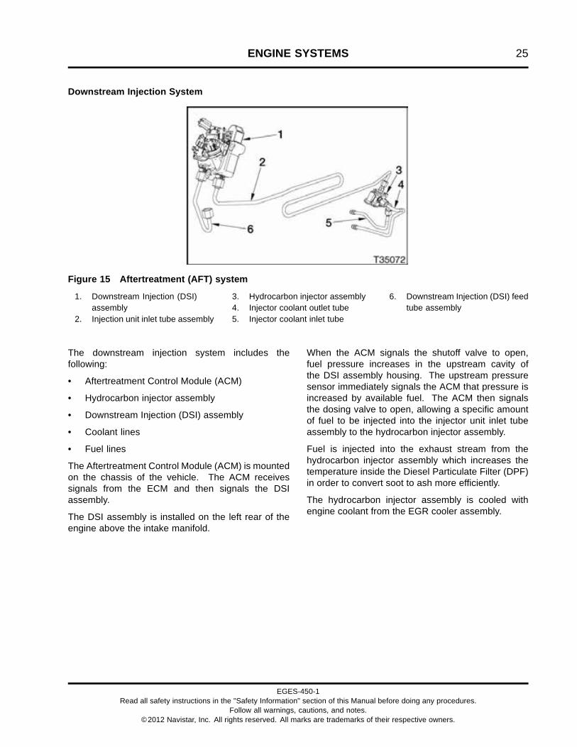
Figure 15 Aftertreatment (AFT) system
1. Downstream Injection (DSI)assembly
2. Injection unit inlet tube assembly
3. Hydrocarbon injector assembly4. Injector coolant outlet tube5. Injector coolant inlet tube
6. Downstream Injection (DSI) feedtube assembly
The downstream injection system includes thefollowing:
• Aftertreatment Control Module (ACM)
• Hydrocarbon injector assembly
• Downstream Injection (DSI) assembly
• Coolant lines
• Fuel lines
The Aftertreatment Control Module (ACM) is mountedon the chassis of the vehicle. The ACM receivessignals from the ECM and then signals the DSIassembly.
The DSI assembly is installed on the left rear of theengine above the intake manifold.
When the ACM signals the shutoff valve to open,fuel pressure increases in the upstream cavity ofthe DSI assembly housing. The upstream pressuresensor immediately signals the ACM that pressure isincreased by available fuel. The ACM then signalsthe dosing valve to open, allowing a specific amountof fuel to be injected into the injector unit inlet tubeassembly to the hydrocarbon injector assembly.
Fuel is injected into the exhaust stream from thehydrocarbon injector assembly which increases thetemperature inside the Diesel Particulate Filter (DPF)in order to convert soot to ash more efficiently.
The hydrocarbon injector assembly is cooled withengine coolant from the EGR cooler assembly.
EGES-450-1Read all safety instructions in the "Safety Information" section of this Manual before doing any procedures.
Follow all warnings, cautions, and notes.©2012 Navistar, Inc. All rights reserved. All marks are trademarks of their respective owners.

26 ENGINE SYSTEMS
Fuel Management System
Figure 16 Fuel management system
The fuel management system includes the following:
• Lubrication system
• Injection Control Pressure (ICP) system
• Engine Compression Brake (ECB)
• Fuel supply system
• Fuel injectors
• Electronic control system
EGES-450-1Read all safety instructions in the "Safety Information" section of this Manual before doing any procedures.
Follow all warnings, cautions, and notes.©2012 Navistar, Inc. All rights reserved. All marks are trademarks of their respective owners.

ENGINE SYSTEMS 27
ICP System
Figure 17 Injection Control Pressure (ICP) system
1. Engine Compression BrakePressure (ECBP) sensor
2. O-ring (2)3. Engine Compression Brake
(ECB) valve4. Injection Control Pressure (ICP)
sensor
5. High-pressure oil manifold6. Injector oil inlet from
high-pressure oil manifold7. Oil outlet (2)8. Fuel inlet port (4)9. 70 degree elbow10. High-pressure oil hose
11. Injection Pressure Regulator(IPR) valve
12. Oil inlet from front cover reservoir13. High-pressure oil pump
assembly14. Fuel injector assembly (6)
EGES-450-1Read all safety instructions in the "Safety Information" section of this Manual before doing any procedures.
Follow all warnings, cautions, and notes.©2012 Navistar, Inc. All rights reserved. All marks are trademarks of their respective owners.

28 ENGINE SYSTEMS
High-Pressure Oil Flow
The lubrication system supplies the oil reservoirlocated in the front cover. The reservoir provides oilfor the high-pressure oil pump. The pump is mountedon the backside of the front cover and is gear drivenby the upper idler gear.
High-pressure oil is directed to the high-pressure oilhose, cylinder head passage, and high-pressure oilmanifold.
High-pressure oil is used by the fuel injectors topressurize and inject fuel in the cylinders. This occurswhen the OPEN coil for each fuel injector is energized.
Excess high-pressure oil is directed to the crankcasesump by the Injection Pressure Regulator (IPR) valve.The IPR valve is controlled by the Electronic ControlModule (ECM) to maintain a desired injection controlpressure.
If equipped with the optional engine brake, somehigh-pressure oil is directed internally to the enginebrake pistons when the engine compression brake isactivated. Since these two systems share a commongallery, a problem with the engine compression brakesystem can adversely affect injection control pressureand vise versa.
ICP Closed Loop System
Figure 18 ICP closed loop system
The ICP (Injection Control Pressure) system is aclosed loop system that uses the ICP sensor tocontinuously provide feedback to the ECM. The ECM
commands the IPR duty cycle to adjust pressure tomatch engine requirements.
EGES-450-1Read all safety instructions in the "Safety Information" section of this Manual before doing any procedures.
Follow all warnings, cautions, and notes.©2012 Navistar, Inc. All rights reserved. All marks are trademarks of their respective owners.

ENGINE SYSTEMS 29
ICP Control System
Figure 19 ICP control system
The IPR valve receives a Pulse Width Modulated(PWM) signal from the ECM. This controls the on andoff time the IPR valve is energized. The on/off timeis controlled by the ECM to meet calibrated desiredvalues.
The IPR valve is mounted in the body of thehigh-pressure pump. The IPR valve maintainsdesired ICP by dumping excess oil back into thecrankcase sump.
As demand for ICP increases, the ECM increases thecurrent to the IPR valve solenoid. When demandfor ICP decreases, the duty cycle to the IPR valvedecreases and more oil is allowed to flow back to thecrankcase sump.
When the ICP electrical signal is out-of-range, theECM sets a fault code.
When ICP signals are out-of-range, the ECM ignoresthem and goes into open loop operation. The IPRvalve will operate from programmed default values.
The ICP sensor is installed in the high-pressure oilmanifold under the valve cover.
EGES-450-1Read all safety instructions in the "Safety Information" section of this Manual before doing any procedures.
Follow all warnings, cautions, and notes.©2012 Navistar, Inc. All rights reserved. All marks are trademarks of their respective owners.

30 ENGINE SYSTEMS
Fuel Injector
Figure 20 Fuel injector
1. Upper O-ring2. Lower O-ring3. Nozzle gasket4. Injector nozzle5. Fuel inlet port
Fuel Injector Features
Two 50 volt, 25 amp coils control a spool valve thatdirects oil flow in and out of the injector. Each injectorhas a single four pin connector that connects to thevalve cover gasket assembly.
Injector Coils and Spool Valve
An OPEN coil and a CLOSE coil on the injector movethe spool valve from side to side using magnetic force.The spool has two positions:
• When the spool valve is open, oil flows into theinjector from the high-pressure oil manifold.
• When the spool valve is closed, oil exits fromthe top of the fuel injector and drains back to thecrankcase.
Intensifier Piston and Plunger
When the spool valve is open, high-pressure oil entersthe injector, pushing down the intensifier piston andplunger. Since the intensifier piston is 10 times greaterin surface area than the plunger, the fuel injectionpressure is also 10 times greater than injection controlpressure on the plunger.
Plunger and Barrel
Fuel pressure builds at the base of the plunger in thebarrel. When the intensifier piston pushes the plungerdown, the plunger increases fuel pressure in the barrel10 times greater than injection control pressure. Theplunger has a hardened coating to resist scuffing.
Injector Needle
The injector needle opens inward when fuel pressureovercomes the Valve Opening Pressure (VOP). Fuelis atomized at high-pressure through the nozzle tip.
EGES-450-1Read all safety instructions in the "Safety Information" section of this Manual before doing any procedures.
Follow all warnings, cautions, and notes.©2012 Navistar, Inc. All rights reserved. All marks are trademarks of their respective owners.

ENGINE SYSTEMS 31
Fuel Injector Operation
The injector operation has three stages:
• Fill stage
• Injection
• End of injection
Figure 21 Fuel injector cross section
Fill Stage
During the fill stage, both coils are de-energized andthe spool valve is closed. High-pressure oil from thehigh-pressure oil manifold is stopped at the spoolvalve.
Low-pressure fuel fills the four ports and entersthrough the edge filter on its way to the chamberbeneath the plunger. The needle control spring holdsthe needle onto its seat to prevent fuel from enteringthe combustion chamber.
Injection
1. A pulse-width controlled current energizes theOPEN coil. Magnetic force moves the spoolvalve open. High-pressure oil flows past thespool valve and onto the top of the intensifierpiston. Oil pressure overcomes the force ofthe intensifier piston spring and the intensifierstarts to move down. An increase in fuelpressure under the plunger seats the fuel inletcheck ball, and fuel pressure starts to build onthe needle.
2. The pulse-width controlled current to theOPEN coil is shut off, but the spool valveremains open. High-pressure oil from thehigh-pressure oil manifold continues toflow past the spool valve. The intensifierpiston and plunger continue to move and fuelpressure increases in the barrel. When fuelpressure rises above the VOP, the needlelifts off its seat and injection begins.
End of Injection
1. When the ECM determines that the correctinjector on-time has been reached (thecorrect amount of fuel has been delivered),the ECM sends a pulse-width controlledcurrent to the CLOSE coil of the injector.The current energizes the CLOSE coiland magnetic force closes the spool valve.High-pressure oil is stopped against the spoolvalve.
2. The pulse-width controlled current to closethe coil is shut off, but the spool valve remainsclosed. Oil above the intensifier piston flowspast the spool valve through the exhaustports. The intensifier piston and plungerreturn to their initial positions. Fuel pressuredecreases until the needle control springforces the needle back on its seat.
EGES-450-1Read all safety instructions in the "Safety Information" section of this Manual before doing any procedures.
Follow all warnings, cautions, and notes.©2012 Navistar, Inc. All rights reserved. All marks are trademarks of their respective owners.

32 ENGINE SYSTEMS
Fuel Supply System
Figure 22 Low-pressure fuel system
1. Cylinder Head2. Fuel injector assembly (6)3. Fuel filter cap4. M8 x 75 stud bolt (3)5. Diagnostic coupling assembly
and dust cap6. Water drain valve assembly7. M8 x 75 bolt
8. Water In Fuel (WIF) sensor9. 250 watt heater assembly
(optional)10. Voss® Stop Flow adapter
assembly (fuel inlet)11. Fuel filter assembly (with
optional heater)12. Electric fuel pump assembly
13. Low pressure fuel rail (cast inintake manifold)
EGES-450-1Read all safety instructions in the "Safety Information" section of this Manual before doing any procedures.
Follow all warnings, cautions, and notes.©2012 Navistar, Inc. All rights reserved. All marks are trademarks of their respective owners.

ENGINE SYSTEMS 33
Fuel Supply System Flow
Figure 23 Fuel flow
The electric fuel pump draws fuel through the fuel linesfrom the fuel tank. Fuel enters the fuel filter assemblyand passes through the 100 micron strainer.
An optional 250 watt electric heating element isavailable to warm incoming fuel to prevent waxingand optimize cold weather performance. The heateris installed in the fuel filter assembly, below theelectric fuel pump.
Fuel flows from the strainer through the electric fuelpump to the fuel filter for further conditioning.
If water is in the fuel, the fuel filter element repels thewater. The water is collected at the bottom of the mainfilter element cavity in the fuel filter assembly.
Fuel flows through the 5 micron filter element and thestandpipe. The filter element removes debris from thefuel. The standpipe prevents fuel from draining fromthe fuel rail during service.
EGES-450-1Read all safety instructions in the "Safety Information" section of this Manual before doing any procedures.
Follow all warnings, cautions, and notes.©2012 Navistar, Inc. All rights reserved. All marks are trademarks of their respective owners.

34 ENGINE SYSTEMS
Figure 24 Fuel filter assembly components
1. M5 x 25 screw (3)2. Electric fuel pump3. Pump cover and housing O-ring
(2)4. Pump adapter5. 3.53 x 40.87 ID O-ring6. Pump strainer7. M6 screw (3)8. Port cover9. Port cover seal10. Fuel filter cap11. O-ring gasket12. Fuel filter element13. Irregular molded gasket
14. Fuel filter assembly with heater15. M8 x 75 stud bolt (3)16. Fuel pressure regulator valve
assembly17. Fuel pressure regulator spring18. Cover plate seal19. Bottom cover plate20. Sensor O-ring21. Fuel Delivery Pressure (FDP)
sensor22. M6 screw (7)23. O-ring24. Water drain valve assembly25. M5 x 18 Torx® screw (2)
26. O-ring seal27. Water In Fuel (WIF) sensor28. 250 watt heater assembly
(optional)29. Heater plug O-ring gasket30. Dust cap31. Diagnostic coupling32. #906 O-ring33. M8 x 75 bolt34. Voss® Stop Flow adapter
assembly (fuel inlet)35. Gasket
EGES-450-1Read all safety instructions in the "Safety Information" section of this Manual before doing any procedures.
Follow all warnings, cautions, and notes.©2012 Navistar, Inc. All rights reserved. All marks are trademarks of their respective owners.

ENGINE SYSTEMS 35
When the maximum amount of water is collected inthe element cavity, the WIF sensor sends a signalto the Electronic Control Module (ECM). The ECMturns on the amber Water In Fuel lamp located on theinstrument panel.
A water drain valve is located on the fuel filterassembly and can be opened to drain contaminants(usually water) from the assembly.
A fuel pressure regulator valve is built into the fuel filterassembly. The regulator valve is calibrated to relieveexcessive fuel pressure. Excess fuel is sent througha fuel return line back to the fuel tank. Return fuel isnot filtered.
Fuel continuously flows from the top of the filterelement cavity, through a 0.2 mm air bleed orifice(filter center tube feature), and into the return fuel line.This aids in removing trapped air from the elementcavity as a result of servicing.
When the fuel filter is removed, a drain-to-tank portvalve is opened. Fuel present in the filter assembly
then drains out and back to the tank to provideimproved cleanliness during servicing. When fuellines are removed, a check valve eliminates spillageand ensures fuel line cleanliness.
The Fuel Delivery Pressure (FDP) sensor detectslow fuel pressure caused by a fuel restriction or dirtyfuel filter. The FDP sensor sends a signal to theECM when pressure is below programmed valuesfor various engine conditions. The ECM turns on anamber FUEL FILTER lamp located on the instrumentpanel.
Filtered fuel flows from the fuel filter assembly into thefuel rail. The fuel rail is an integral part of the intakemanifold. Fuel flows into six cylinder head passagesto each fuel injector.
When the fuel injectors are activated, fuel flows fromthe fuel passages through the injector inlet ports andinto the fuel injectors.
EGES-450-1Read all safety instructions in the "Safety Information" section of this Manual before doing any procedures.
Follow all warnings, cautions, and notes.©2012 Navistar, Inc. All rights reserved. All marks are trademarks of their respective owners.

36 ENGINE SYSTEMS
Engine Lubrication System
Figure 25 Lubrication system
1. Unfiltered oil2. Cooled unfiltered oil3. Filtered oil4. Crankcase breather assembly5. Oil pump6. Front cover7. Reservoir for high-pressure oil
pump8. Unfiltered oil gallery9. Pick-up tube
10. Dual stage turbocharger11. Oil cooler12. Oil filter13. Oil cooler module assembly14. Oil pressure regulator relief
valve15. Regulator relief valve drain to
sump16. Oil pan assembly17. Crankshaft
18. Piston cooling tube (6)19. Main filtered oil gallery20. Camshaft21. Crankcase22. Vertical gallery23. Cylinder head24. Valve cover25. Rocker arm assembly oil gallery26. Air compressor (optional)
EGES-450-1Read all safety instructions in the "Safety Information" section of this Manual before doing any procedures.
Follow all warnings, cautions, and notes.©2012 Navistar, Inc. All rights reserved. All marks are trademarks of their respective owners.

ENGINE SYSTEMS 37
Oil Flow
Figure 26 Lubrication system
Unfiltered oil is drawn from the oil pan through thepickup tube and front cover passage by the crankshaftdriven oil pump. Pressurized oil is forced through afront cover passage, into the crankcase gallery, andto the oil system module assembly. Oil flow into theoil cooler is controlled by the thermal bypass valve.
The thermal bypass valve allows unfiltered oil tobypass the oil cooler when the oil temperature is cold,and flow directly to the oil filter. As the oil temperaturebegins to warm, the thermal bypass valve begins toopen. This allows unfiltered oil to flow into the oilcooler and oil filter.
When the oil temperature is hot, the thermal bypassvalve is fully open. This allows all unfiltered oil to flowthrough the oil cooler before entering the oil filter.
Unfiltered oil moves through plates in the oil coolerheat exchanger. Engine coolant flows around theplates to cool the surrounding oil.
Oil that exits or bypasses the oil cooler mixes andenters the spin-on oil filter. Oil flows from outside thefilter element towards the inside to remove debris.
When the filter is restricted, the oil filter bypass(located in the oil filter can) opens and allows oil tobypass the filter to maintain engine lubrication. Thefilter bypass valve opens when pressure reaches 414kPa (60 psi).
After passing through the filter, the oil travels past theoil pressure regulator. The regulator directs excessoil back to the oil pan to maintain oil pressure at amaximum of 393 kPa (57 psi).
Clean regulated oil enters the main oil gallery of theengine to lubricate the crankshaft, camshaft, andtappets. The crankshaft has cross-drillings that directoil to the connecting rods.
Oil is also provided to the high-pressure reservoirthrough a passage in the front cover.
Piston cooling jets continuously direct cooled oil to thebottom of the piston crowns.
Oil is provided to the cylinder head from the rearcam bearing through a passage at the rear of thecrankcase. Oil flows through a passage in the
EGES-450-1Read all safety instructions in the "Safety Information" section of this Manual before doing any procedures.
Follow all warnings, cautions, and notes.©2012 Navistar, Inc. All rights reserved. All marks are trademarks of their respective owners.

38 ENGINE SYSTEMS
cylinder head and rear rocker shaft support, thenenters the hollow rocker shaft, which lubricates therocker arms.
The crankcase breather assembly oil separator isdriven by unfiltered oil pressure taken from the rightside of the crankcase. Oil flows from the crankcaseinto the breather assembly oil separator. Passagesdirect the oil through a pressed brass nozzle thatcontrols oil flow into the drive oil separator wheel.Oil drains into the base and mixes with oil from thebreather system. The collected oil drains into thecrankcase and then into the oil pan.
The turbocharger is lubricated with filtered oil froma supply tube assembly that connects the oil cooler
module assembly to the center housing of eachturbocharger. Oil drains back to the crankcasethrough drain tubes connected to the base of thebreather housing assembly.
The optional air compressor is lubricated with filteredengine oil through a flexible hose. The hose isconnected to a tee on the left side of the crankcasenear the Engine Oil Pressure (EOP) sensor. Oil drainsinto the front cover and to the oil pan. Oil can alsodrain from the bottom of the air compressor througha tube into the crankcase.
The front gear train is splash lubricated with oilthat drains from the high-pressure reservoir and theoptional air compressor.
EGES-450-1Read all safety instructions in the "Safety Information" section of this Manual before doing any procedures.
Follow all warnings, cautions, and notes.©2012 Navistar, Inc. All rights reserved. All marks are trademarks of their respective owners.

ENGINE SYSTEMS 39
Engine Cooling System
Figure 27 Cooling system components and flow
Cooling System Description
The engine cooling system includes the following:
• Chassis mounted radiator
• Low temperature radiator (if equipped)
• Low temperature radiator thermostat (if equipped)
• Interstage cooler (if equipped)
• Coolant fan
• Water inlet elbow
• Front engine cover
• Water pump
• Crankcase
• Cylinder sleeves
• Cylinder head
• Oil cooler module assembly
• Air compressor
• Thermostat
• Coolant supply housing/coolant port
• EGR cooler
• Coolant surge tank
• Coolant heater (if equipped)
The water pump pushes coolant into the crankcase,low temperature radiator, and EGR cooler.
Coolant flows to the crankcase and through the waterjackets from front to rear. Coolant flows aroundthe cylinder liners to absorb heat from combustion.Coolant may also pass by the optional engine coolantheater.
Swirling coolant flow in the cylinder liner jacketsdirects coolant through passages in the cylinder headgasket and upwards into the cylinder head.
Coolant flows through the cylinder head water jacketstowards the thermostat cavity at the front of thecylinder head. When the thermostat is closed, coolantis directed through the bypass port, crankcase, frontcover, and into the water pump. When the thermostat
EGES-450-1Read all safety instructions in the "Safety Information" section of this Manual before doing any procedures.
Follow all warnings, cautions, and notes.©2012 Navistar, Inc. All rights reserved. All marks are trademarks of their respective owners.

40 ENGINE SYSTEMS
is open, the bypass port is blocked, and coolant isdirected through the radiator.
Coolant passes through the radiator and is cooled bymoving air from the coolant fan. Coolant returns to theengine through the inlet elbow and front cover.
The air compressor is cooled with engine coolantsupplied by a hose from the left side of the crankcase.Coolant passes through the air compressor andreturns to the cylinder head through a passage in thecrankcase.
The oil cooler module assembly receives coolantfrom a passage in the crankcase. Coolant passesbetween the oil cooler plates and returns through atube connected to the coolant supply housing.
The EGR cooler receives coolant from the waterpump through a supply tube at the rear of the frontcover. Coolant passing through the EGR cooler, flowsthrough the cooler plates, cools the exhaust gas, andexits through a tube to the rear of the front cover thatreturns coolant to the pump inlet. The hydrocarboninjector assembly receives and returns coolant to theEGR cooler.
The EGR coolant supply tube also branches off tothe low temperature radiator and to the interstagecooler (above 245 hp), if equipped. For engines withratings above 245 hp, the coolant is routed throughthe low temperature thermostat, then through thelow temperature radiator to the interstage cooler.Coolant is regulated by the low temperature radiatorthermostat. Warm coolant is directed to the lowtemperature radiator and into the interstage cooler.Cold coolant bypasses the low temperature radiatorand moves directly into the interstage cooler.
The interstage cooler uses coolant to lowerthe charged air temperature that exits from theturbocharger low-pressure compressor and entersthe turbocharger high-pressure compressor.
The surge tank provides expansion space for coolantand deaerates the cooling system. The following fourvents provide coolant to the tank:
• Engine vent (top of coolant supply housing)
• EGR vent (top of EGR cooler)
• Main radiator vent (top of radiator)
• Interstage cooler vent (top of interstage cooler)
The surge tank returns coolant through the surge line,back to the water pump inlet.
Cab heat is provided by the heater core, whichreceives warmed coolant from the coolant supplyhousing.
Cooling System Components
Coolant Heater (optional)
An optional coolant heater is available to warm enginecoolant in cold weather. The coolant heater warms thecoolant surrounding the cylinders. Warmed enginecoolant aids in cold engine start-up and performance.The coolant heater is installed on the left side of thecrankcase, in front of the Electronic Control Module(ECM).
Thermostat Operation
Coolant travels through two ports after it passesthrough the thermostat. One port directs coolantto the radiator when the engine is at operatingtemperature. The other port directs coolant to thewater pump until the engine reaches operatingtemperature. The thermostat begins to open at 88 °C(190 °F) and is fully open at 96 °C (205 °F).
EGES-450-1Read all safety instructions in the "Safety Information" section of this Manual before doing any procedures.
Follow all warnings, cautions, and notes.©2012 Navistar, Inc. All rights reserved. All marks are trademarks of their respective owners.
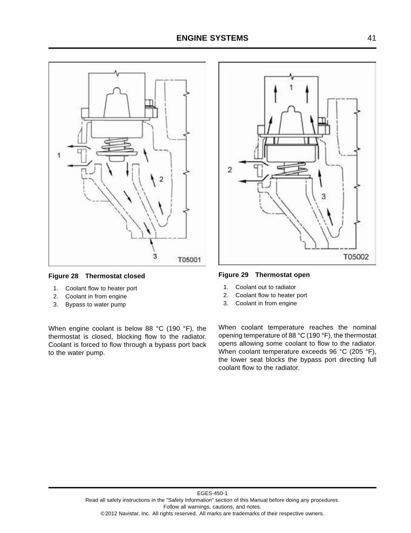
ENGINE SYSTEMS 41
Figure 28 Thermostat closed
1. Coolant flow to heater port2. Coolant in from engine3. Bypass to water pump
When engine coolant is below 88 °C (190 °F), thethermostat is closed, blocking flow to the radiator.Coolant is forced to flow through a bypass port backto the water pump.
Figure 29 Thermostat open
1. Coolant out to radiator2. Coolant flow to heater port3. Coolant in from engine
When coolant temperature reaches the nominalopening temperature of 88 °C (190 °F), the thermostatopens allowing some coolant to flow to the radiator.When coolant temperature exceeds 96 °C (205 °F),the lower seat blocks the bypass port directing fullcoolant flow to the radiator.
EGES-450-1Read all safety instructions in the "Safety Information" section of this Manual before doing any procedures.
Follow all warnings, cautions, and notes.©2012 Navistar, Inc. All rights reserved. All marks are trademarks of their respective owners.

42 ENGINE SYSTEMS
Low Temperature Radiator (LTR) ThermostatOperation
Figure 30 LTR thermostat
1. Thermostat outlet to low temperature radiator2. Thermostat inlet3. Thermostat bypass to ISC
Engines equipped with Interstage Cooler (ISC) willalso have a Low Temperature Radiator (LTR) and LTRthermostat. The LTR thermostat is a wax elementthermostat in a housing with one inlet port and twooutlet ports. During cold engine operation (thermostatclosed), coolant is directed to the ISC directly, throughthe bypass port. At normal operating temperature(thermostat open), coolant is directed to the LTR firstand then to the ISC. The thermostat begins to openat 90 °C (194 °F) and is fully open at 98 °C (209 °F).The LTR thermostat is installed on the chassis nearthe LTR.
EGES-450-1Read all safety instructions in the "Safety Information" section of this Manual before doing any procedures.
Follow all warnings, cautions, and notes.©2012 Navistar, Inc. All rights reserved. All marks are trademarks of their respective owners.

ENGINE SYSTEMS 43
Electronic Control SystemElectronic Control System Components
Figure 31 Electronic Control System
EGES-450-1Read all safety instructions in the "Safety Information" section of this Manual before doing any procedures.
Follow all warnings, cautions, and notes.©2012 Navistar, Inc. All rights reserved. All marks are trademarks of their respective owners.

44 ENGINE SYSTEMS
Operation and Function
The Electronic Control Module (ECM) monitors andcontrols engine performance to ensure maximumperformance and adherence to emissions standards.The ECM performs the following functions:
• Provides Reference Voltage (VREF)
• Conditions input signals
• Processes and stores control strategies
• Controls actuators
Reference Voltage (VREF)
The ECM internal Power supply generates 5.0V(Vcc) for the internal components, a referencevoltage of 5.0V for the A/D converters and alsothree independent short circuit protected 5.0Vtracking voltages (V_REF_1, V_REF_2, V_REF_3)for external devices.
• VREF 1 supplies 5 volts to engine sensors
• VREF 2 supplies 5 volts to vehicle aftertreatmentand pedal
• VREF 3 supplies 5 volts to body builder and pedal
Microprocessor
The ECM microprocessor stores operatinginstructions (control strategies) and value tables(calibration parameters). The ECM compares storedinstructions and values with conditioned input valuesto determine the correct strategy for all engineoperations.
Actuator Control
The ECM controls the actuators by applying a lowlevel signal (low side driver) or a high level signal (highside driver). When switched on, the drivers completea ground or power circuit to an actuator.
Actuators are controlled in one of the following ways,depending upon type of actuator:
• Duty cycle (percent time on/off)
• Controlled pulse width
• Switched on or off
Actuators
The ECM controls engine operation with the following:
• Exhaust Gas Recirculation (EGR) valve
• Intake Air Heater (IAH) relay
• Engine Throttle Valve (ETV) and position sensor
• Turbocharger 2 Wastegate Control (TC2WC)valve (turbocharger wastegate actuator)
• Exhaust Back Pressure Valve (EBPV)
• Engine Compression Brake (ECB) valve
• Injection Pressure Regulator (IPR) valve
Exhaust Gas Recirculation (EGR) Valve
The EGR valve controls the flow of exhaust gases tothe air and EGR mixer duct.
The EGR valve receives the desired valve positionfrom the ECM for exhaust gas recirculation.
Sensors within the EGR valve provide feedback to theECM on valve position and temperature. A fault codewill be set if the ECM detects an error.
Intake Air Heater (IAH) Relay
The IAH system warms the incoming air supply priorto cranking to aid cold engine starting.
The ECM is programmed to energize the IAHelement through the IAH relay while monitoringcertain programmed conditions for engine coolanttemperature, engine oil temperature, and atmosphericpressure.
The ECM activates the IAH relay. The relay suppliesbattery voltage to the heater elements for a settime, depending on engine coolant temperature andaltitude.
Engine Throttle Valve (ETV) and Position Sensor
The engine throttle valve controls the flow of inletair to regulate operating temperature for exhaustaftertreatment and base engine operation.
The integral throttle actuator controls the enginethrottle valve.
The throttle actuator receives the desired enginethrottle valve position from the ECM to activate the
EGES-450-1Read all safety instructions in the "Safety Information" section of this Manual before doing any procedures.
Follow all warnings, cautions, and notes.©2012 Navistar, Inc. All rights reserved. All marks are trademarks of their respective owners.

ENGINE SYSTEMS 45
throttle valve. The throttle position sensor providesfeedback to the ECM on the throttle valve position.
Turbocharger 2 Wastegate Control (TC2WC) valve(turbocharger wastegate actuator)
The turbocharger wastegate actuator regulates thecharge air pressure by controlling the amount ofexhaust gases that pass through the high-pressureturbine.
The TC2WC valve receives the command signal fromthe ECM. When the charge air pressure demand islow, the TC2WC valve opens, allowing control air tothe turbocharger wastegate actuator. The actuatoropens allowing part of the exhaust gas flow to bypassthe high-pressure turbine.
Exhaust Back Pressure Valve (EBPV)
The Exhaust Back Pressure Valve (EBPV) controlsthe position of the exhaust valve increasing
or decreasing exhaust gas back pressure andtemperature to allow the DOC and DPF to functionefficiently.
Engine Compression Brake (ECB) valve
The Engine Compression Brake (ECB) valve controlspressure entering the brake oil gallery from theinjector oil gallery. This activates the brake actuatorpistons and opens the exhaust valves. The ECBvalve is installed in the center of the high-pressure oilmanifold.
Injection Pressure Regulator (IPR) valve
The Injection Pressure Regulator (IPR) valve is usedto maintain desired injection control pressure. Excesshigh-pressure oil is directed to the crankcase sump bythe IPR valve.
EGES-450-1Read all safety instructions in the "Safety Information" section of this Manual before doing any procedures.
Follow all warnings, cautions, and notes.©2012 Navistar, Inc. All rights reserved. All marks are trademarks of their respective owners.

46 ENGINE SYSTEMS
Engine and Vehicle Sensors
Temperature Sensors
Thermistor Sensors
Figure 32 Thermistor sensor
A thermistor sensor varies electrical resistance withchanges in temperature. Resistance in the thermistordecreases as temperature increases, and increasesas temperature decreases. Thermistors have aresistor that limits current in the ECM to a voltagesignal matched with a temperature value.
The top half of the voltage divider is the current limitingresistor inside the ECM. A thermistor sensor has twoelectrical connectors, signal return and ground. Theoutput of a thermistor sensor is a nonlinear analogsignal.
Thermistor type sensors include the following:
• Engine Coolant Temperature (ECT) sensor
• Engine Oil Temperature (EOT) sensor
• Air Inlet Temperature (AIT) sensor
• Intake Manifold Temperature (IMT) sensor
ECT Sensor
The ECM monitors the ECT signal and uses thisinformation for the instrument panel temperaturegauge, coolant compensation, Engine WarningProtection System (EWPS), and IAH operation. TheECT is a backup, if the EOT is out-of-range. TheECT sensor is installed in the coolant supply housing(refrigerant compressor bracket).
EOT Sensor
The ECM monitors the EOT signal and uses thisinformation to control fuel quantity and timing. TheEOT signal allows the ECM to compensate fordifferences in oil viscosity for temperature changes.The EOT sensor is installed in the rear of the frontcover, to the left of the high-pressure pump assembly.
AIT Sensor
The AIT sensor is integral to the Mass Air Flow (MAF)sensor. The ECM monitors the AIT signal to controlinjector timing and fuel rate during cold starts. TheECM also uses the AIT signal to control EGR positionand engine throttle control.
IMT Sensor
The IMT sensor monitors the air temperature in theintake manifold. The ECM monitors the IMT signalfor EGR operation. The IMT sensor is installed in theintake manifold, to the right of the IMP sensor.
Exhaust Gas Temperature (EGT) sensors
The Aftertreatment System and exhaust manifold usethe following sensors:
• Exhaust Gas Temperature (EGT) sensor
• Diesel Oxidation Catalyst Intake Temperature(DOCIT) sensor
• Diesel Particulate Filter Intake Temperature(DPFIT) sensor
• Diesel Particulate Filter Outlet Temperature(DPFOT) sensor
The Exhaust Gas Temperature (EGT) sensor used inthe exhaust manifold provides a feedback signal to theECM indicating exhaust gas temperature.
The DOCIT sensor provides a feedback signal tothe ECM indicating Diesel Oxidation Catalyst (DOC)intake temperature. The DOCIT sensor is the firsttemperature sensor installed past the turbochargerand just before the DOC.
The DPFIT sensor provides a feedback signal to theECM indicating Diesel Particulate Filter Intake (DPF)intake temperature. The DPFIT sensor is the secondtemperature sensor installed past the turbochargerand just after the DOC.
EGES-450-1Read all safety instructions in the "Safety Information" section of this Manual before doing any procedures.
Follow all warnings, cautions, and notes.©2012 Navistar, Inc. All rights reserved. All marks are trademarks of their respective owners.

ENGINE SYSTEMS 47
The DPFOT sensor provides a feedback signal to theECM indicating DPF outlet temperature. The DPFOTsensor is the third temperature sensor installed pastthe turbocharger and just after the DPF.
During a catalyst regeneration, the ECM monitorsall three sensors along with the Exhaust GasRecirculation (EGR) System and Engine ThrottleValve (ETV).
Variable Capacitance Sensors
Figure 33 Variable capacitance sensor
Variable capacitance sensors measure pressure. Thepressure measured is applied to a ceramic diaphragm.Pressure forces the ceramic material closer to a thinmetal disk. This action changes the capacitance andsubsequently the voltage output of the sensor.
This type of sensor has three wires, VREF, ground anda signal wire.
The sensor receives the VREF and returns an analogsignal voltage to the ECM. The ECM compares thevoltage with pre-programmed values to determinepressure.
The operational range of a variable capacitancesensor is linked to the thickness of the ceramic disk.The thicker the ceramic disk, the more pressure thesensor can measure.
Variable capacitance sensors include the following:
• Fuel Delivery Pressure (FDP) sensor
• Engine Oil Pressure (EOP) sensor
• Exhaust Back Pressure (EBP) sensor
• Mass Air Flow (MAF) sensor
• Intake Manifold Pressure (IMP) sensor
FDP Sensor
The ECM uses the FDP sensor signal to monitorengine fuel pressure and give an indication when thefuel filter needs to be changed. The FDP sensor isinstalled in the fuel filter assembly on the intake sideof the crankcase.
EOP Sensor
The ECM monitors the EOP signal, and uses thisinformation for the instrument panel pressure gaugeand EWPS. The EOP sensor is installed in the intakeside of the crankcase, below the fuel filter assembly.
EBP Sensor
The ECM monitors the exhaust pressure to control theEGR and intake throttle systems. The EBP sensoris installed in a tube mounted on the coolant supplyhousing (refrigerant compressor bracket).
MAF Sensor
The MAF sensor is used for closed loop controlof the EGR valve and ETV. The ECM monitorsthe MAF signal to control the EGR and intake throttlesystems. The MAF sensor also sends air temperatureinformation to the ECM. The MAF sensor is installedin the intake air duct or air cleaner housing.
IMP Sensor
The ECM monitors the IMP signal to control theEGR and intake throttle systems. The IMP sensor isinstalled in the intake manifold, left of the IMT sensor.
EGES-450-1Read all safety instructions in the "Safety Information" section of this Manual before doing any procedures.
Follow all warnings, cautions, and notes.©2012 Navistar, Inc. All rights reserved. All marks are trademarks of their respective owners.
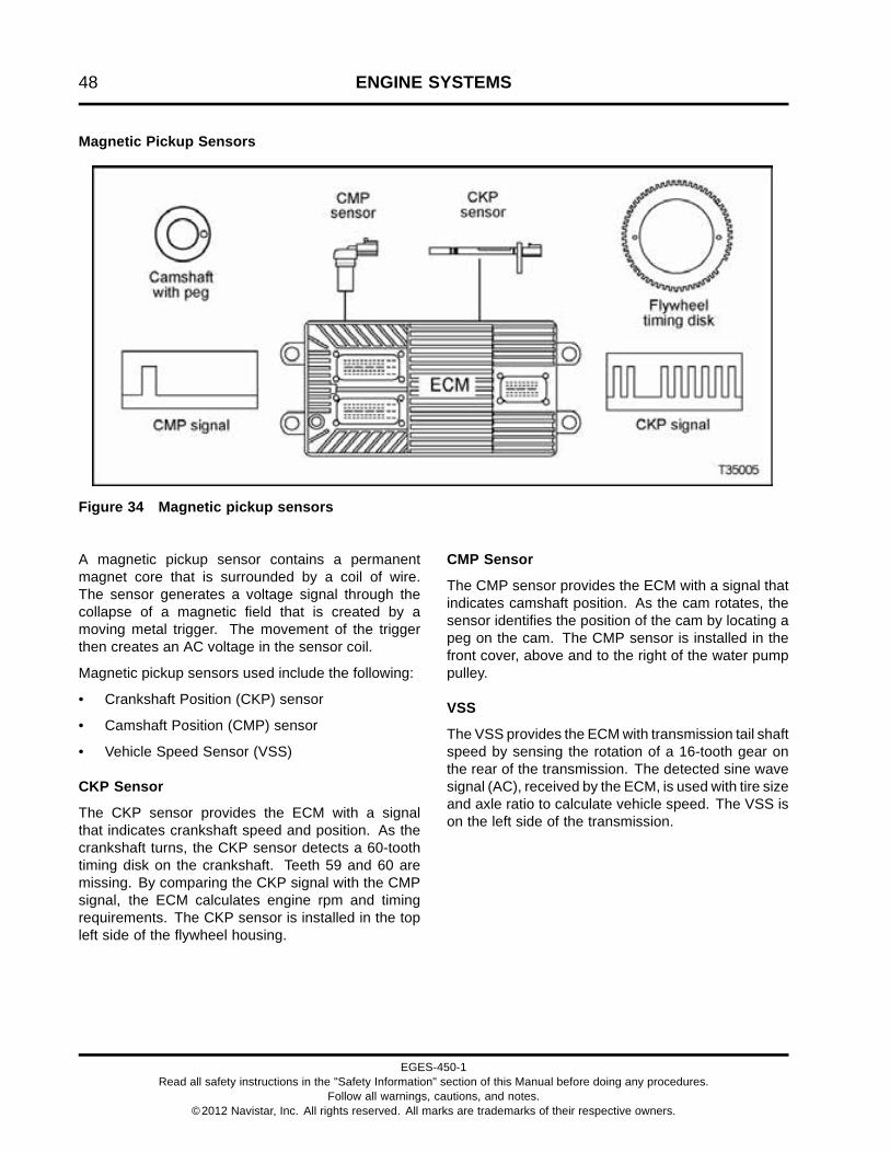
48 ENGINE SYSTEMS
Magnetic Pickup Sensors
Figure 34 Magnetic pickup sensors
A magnetic pickup sensor contains a permanentmagnet core that is surrounded by a coil of wire.The sensor generates a voltage signal through thecollapse of a magnetic field that is created by amoving metal trigger. The movement of the triggerthen creates an AC voltage in the sensor coil.
Magnetic pickup sensors used include the following:
• Crankshaft Position (CKP) sensor
• Camshaft Position (CMP) sensor
• Vehicle Speed Sensor (VSS)
CKP Sensor
The CKP sensor provides the ECM with a signalthat indicates crankshaft speed and position. As thecrankshaft turns, the CKP sensor detects a 60-toothtiming disk on the crankshaft. Teeth 59 and 60 aremissing. By comparing the CKP signal with the CMPsignal, the ECM calculates engine rpm and timingrequirements. The CKP sensor is installed in the topleft side of the flywheel housing.
CMP Sensor
The CMP sensor provides the ECM with a signal thatindicates camshaft position. As the cam rotates, thesensor identifies the position of the cam by locating apeg on the cam. The CMP sensor is installed in thefront cover, above and to the right of the water pumppulley.
VSS
The VSS provides the ECM with transmission tail shaftspeed by sensing the rotation of a 16-tooth gear onthe rear of the transmission. The detected sine wavesignal (AC), received by the ECM, is used with tire sizeand axle ratio to calculate vehicle speed. The VSS ison the left side of the transmission.
EGES-450-1Read all safety instructions in the "Safety Information" section of this Manual before doing any procedures.
Follow all warnings, cautions, and notes.©2012 Navistar, Inc. All rights reserved. All marks are trademarks of their respective owners.

ENGINE SYSTEMS 49
High-pressure Sensors
Figure 35 High-pressure sensor
High-pressure sensors convert pressure to a linearanalog voltage output of 0–5 volts. Pressure to bemeasured exerts force on a diaphragm with a straingauge bonded to it. This diaphragm stretches andcompresses to change mechanical motion into anelectrical signal.
This type of sensor has three wires, VREF, ground anda signal wire.
The sensor is powered by VREF from the ECMand is grounded through the ECM to a commonsensor ground. The ECM compares the voltage withpre-programmed values to determine pressure.
High-pressure sensors include the following:
• Diesel Particulate Filter Differential Pressure(DPFDP) sensor
• Engine Compression Brake Pressure (ECBP)sensor
• Injection Control Pressure (ICP) sensor
DPFDP Sensor
The DPFDP sensor provides a feedback signal to theECM indicating the pressure difference between the
inlet and outlet of the Diesel Particulate Filter (DPF).During a catalyst regeneration, the ECM monitorsthis sensor along with three Aftertreatment Systemthermistor sensors, the EGR System, and the EngineThrottle Valve (ETV).
ECBP
The ECM monitors the ECBP signal to determine oilpressure in the brake gallery of the high-pressure oilmanifold. The ECBP sensor is under the valve cover,forward of the No. 2 fuel injector in the high-pressureoil manifold.
ICP
The ECM monitors the ICP sensor to determineinjection control pressure for engine operation. TheICP sensor is used to control the IPR valve. It providesfeedback to the ECM for Closed Loop IPR control.The ICP sensor is located under the valve cover,forward of the No. 6 fuel injector in the high-pressureoil manifold.
EGES-450-1Read all safety instructions in the "Safety Information" section of this Manual before doing any procedures.
Follow all warnings, cautions, and notes.©2012 Navistar, Inc. All rights reserved. All marks are trademarks of their respective owners.

50 ENGINE SYSTEMS
Potentiometer
Figure 36 Potentiometer
A potentiometer is a variable voltage divider thatsenses the position of a mechanical component.A reference voltage is applied to one end of thepotentiometer. Mechanical rotary or linear motionmoves the wiper along the resistance material,changing voltage at each point along the resistivematerial. Voltage is proportional to the amount ofmechanical movement.
APP
The APP provides the ECM with a feedback signal(linear analog voltage) that indicates the operator’sdemand for power. There are two potentiometerswithin the APP sensor. The APP is installed in thecab on the accelerator pedal.
EGES-450-1Read all safety instructions in the "Safety Information" section of this Manual before doing any procedures.
Follow all warnings, cautions, and notes.©2012 Navistar, Inc. All rights reserved. All marks are trademarks of their respective owners.

ENGINE SYSTEMS 51
Switches
Figure 37 Switch
Switch sensors indicate position, level, or status.They operate open or closed, regulating the flow ofcurrent. A switch sensor can be a voltage input switchor a grounding switch. A voltage input switch suppliesthe ECM with a voltage when it is closed. A groundingswitch grounds the circuit when closed, causing azero voltage signal. Grounding switches are usuallyinstalled in series with a current limiting resistor.
Switches include the following:
• Driveline Disengagement Switch (DDS)
• Engine Coolant Level (ECL)
• Water In Fuel (WIF)
DDS
The DDS determines if a vehicle is in gear. Formanual transmissions, the clutch switch serves asthe DDS. For automatic transmissions, the neutralindicator switch or datalink communication functionsas the DDS.
ECL
ECL is part of the Engine Warning Protection System(EWPS). The ECL switch is used in plastic deaerationtanks. When a magnetic switch is open, the tank isfull.
If engine coolant is low, the switch closes and the redENGINE lamp on the instrument panel is illuminated.
WIF
A Water In Fuel (WIF) sensor in the fuel filter assemblyis used to detect water in the fuel. The resistance ofthe WIF sensor circuit changes when the water level inthe fuel filter assembly reaches the sensor. The ECMthen sends a message to illuminate the amber waterin fuel lamp, alerting the operator. The WIF is installedin the side of the fuel filter assembly.
EGES-450-1Read all safety instructions in the "Safety Information" section of this Manual before doing any procedures.
Follow all warnings, cautions, and notes.©2012 Navistar, Inc. All rights reserved. All marks are trademarks of their respective owners.

52 ENGINE SYSTEMS
Engine Throttle Valve Control System
Figure 38 Engine throttle valve control system
The Engine Throttle Valve (ETV) is controlled to limitinlet air. As part of the air management system, theETV is controlled by the ECM (closed loop) based oninput from the Mass Air Flow (MAF) sensor for properemissions control.
The ETV is also used to help control inlet air duringa Diesel Particulate Filter (DPF) regeneration processof the aftertreatment system. It maintains vehicle andengine performance during regenerations.
EGES-450-1Read all safety instructions in the "Safety Information" section of this Manual before doing any procedures.
Follow all warnings, cautions, and notes.©2012 Navistar, Inc. All rights reserved. All marks are trademarks of their respective owners.

ENGINE SYSTEMS 53
Exhaust and Engine Brake SystemExhaust Brake
Figure 39 Exhaust brake system
The exhaust brake is available for all ratings and aidsin the deceleration rate of vehicles.
The exhaust brake is an exhaust back pressure brakesystem that provides improved braking performance.
The operator can enable the brake function bytoggling an instrument panel mounted switch ON orOFF.
EGES-450-1Read all safety instructions in the "Safety Information" section of this Manual before doing any procedures.
Follow all warnings, cautions, and notes.©2012 Navistar, Inc. All rights reserved. All marks are trademarks of their respective owners.
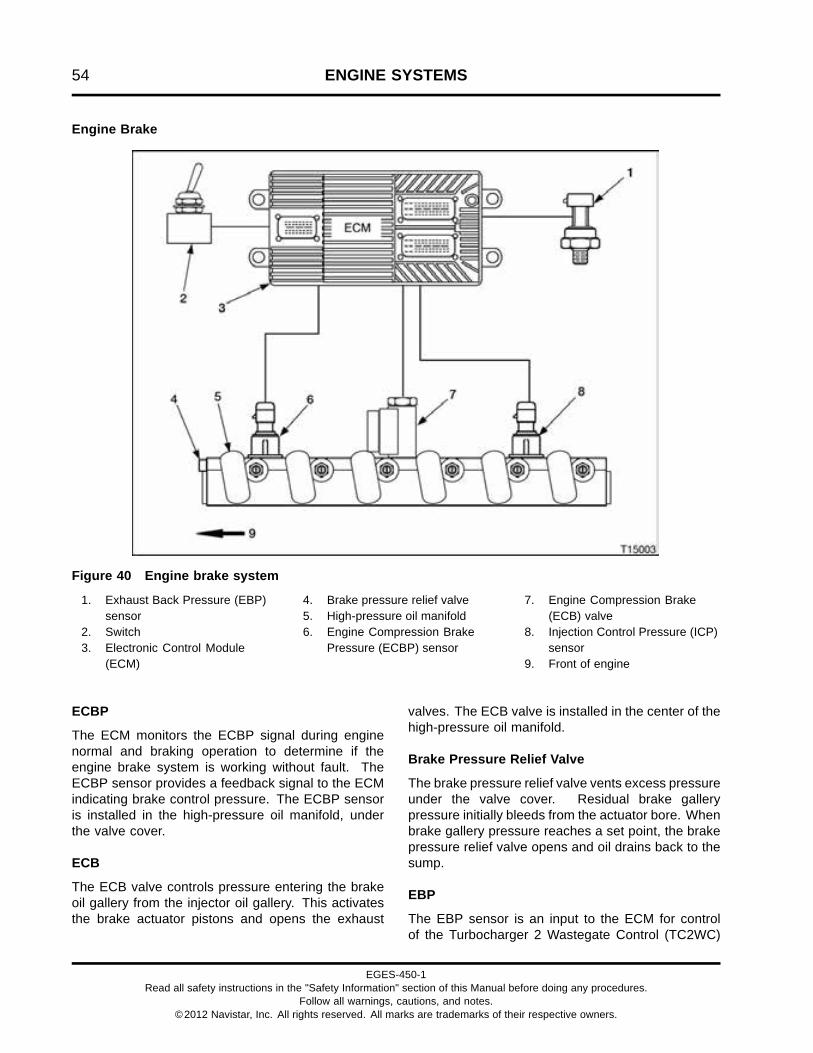
54 ENGINE SYSTEMS
Engine Brake
Figure 40 Engine brake system
1. Exhaust Back Pressure (EBP)sensor
2. Switch3. Electronic Control Module
(ECM)
4. Brake pressure relief valve5. High-pressure oil manifold6. Engine Compression Brake
Pressure (ECBP) sensor
7. Engine Compression Brake(ECB) valve
8. Injection Control Pressure (ICP)sensor
9. Front of engine
ECBP
The ECM monitors the ECBP signal during enginenormal and braking operation to determine if theengine brake system is working without fault. TheECBP sensor provides a feedback signal to the ECMindicating brake control pressure. The ECBP sensoris installed in the high-pressure oil manifold, underthe valve cover.
ECB
The ECB valve controls pressure entering the brakeoil gallery from the injector oil gallery. This activatesthe brake actuator pistons and opens the exhaust
valves. The ECB valve is installed in the center of thehigh-pressure oil manifold.
Brake Pressure Relief Valve
The brake pressure relief valve vents excess pressureunder the valve cover. Residual brake gallerypressure initially bleeds from the actuator bore. Whenbrake gallery pressure reaches a set point, the brakepressure relief valve opens and oil drains back to thesump.
EBP
The EBP sensor is an input to the ECM for controlof the Turbocharger 2 Wastegate Control (TC2WC)
EGES-450-1Read all safety instructions in the "Safety Information" section of this Manual before doing any procedures.
Follow all warnings, cautions, and notes.©2012 Navistar, Inc. All rights reserved. All marks are trademarks of their respective owners.

ENGINE SYSTEMS 55
valve. The TC2WC valve controls the turbochargerwastegate actuator. The EBP sensor is mounted on atube plumbed to the exhaust manifold on the exhaustside of the engine.
High-pressure Oil Manifold
The high-pressure oil manifold has two internalseparated oil galleries. The manifold supplieshigh-pressure oil to each fuel injector during normaloperation. High-pressure oil is directed to the brakepistons during engine brake operation.
Operation
During engine brake operation, The ECB valve opensto supply high-pressure oil to each brake actuatorpiston. These brake actuator pistons hold the exhaustvalves partially open.
Figure 41 Engine compression brake valve and brake actuator – OFF
1. High-pressure oil manifold2. High-pressure oil gallery3. Brake oil gallery
4. Engine compression brake valve5. Brake actuator piston assembly6. Exhaust valve bridge
7. Valve lash (actuator retracted)8. Oil inlet
During normal engine operation, oil in thehigh-pressure manifold goes to the fuel injectors only.The engine compression brake valve, mounted in the
high-pressure oil manifold, is closed to prevent oilfrom entering the brake gallery.
EGES-450-1Read all safety instructions in the "Safety Information" section of this Manual before doing any procedures.
Follow all warnings, cautions, and notes.©2012 Navistar, Inc. All rights reserved. All marks are trademarks of their respective owners.

56 ENGINE SYSTEMS
Figure 42 Engine compression brake valve and brake actuator – ON
1. High-pressure oil manifold2. High-pressure oil flow to brake
oil gallery3. Brake oil gallery
4. Engine compression brake valve5. Brake actuator piston assembly6. Exhaust valve bridge7. Valve lash (actuator deployed)
8. Normal oil seepage9. Oil inlet
The ECM monitors the following criteria to make surecertain conditions are met:
• Anti-lock Brake System (ABS) (inactive)
• RPM (greater than 1200)
• APP (less than 5%)
• EOT (greater than or equal to 60 °C [140 °F])
• Operator input switches (On/Off)
If On is selected, and the preceding criteria are met,the engine brake will activate.
When the engine brake is activated, the ECM providesthe power to activate the Engine Compression Brake(ECB) valve to allow oil from the injector oil gallery toflow to the brake oil gallery. High oil pressure activatesthe brake actuator pistons to open the exhaust valves.
Vehicle momentum is absorbed by the resultingcompression release of the engine power cylinderswhen pistons are near the top of their stroke.
During an ABS event, the engine brake is deactivated.The engine brake is reactivated once the ABS eventis over.
The ECM removes the power source from the ECBvalve to deactivate the engine brake. Residual brakegallery pressure initially bleeds from the actuator bore.When brake gallery pressure bleeds down the brakepressure relief valve opens, and oil drains back tosump.
Operation Modes
The engine brake system provides threeprogrammable modes of operation based onterrain, driving conditions, or driver preference.
Coast Mode
When the coast mode is programmed, the brakesystem will activate only when the driver appliesthe vehicle service brake. The coast mode allows
EGES-450-1Read all safety instructions in the "Safety Information" section of this Manual before doing any procedures.
Follow all warnings, cautions, and notes.©2012 Navistar, Inc. All rights reserved. All marks are trademarks of their respective owners.

ENGINE SYSTEMS 57
the vehicle to coast without automatic brake systemactivation.
Latched Mode
When the latch mode is programmed, the brakesystem will activate when the driver releases theaccelerator pedal. The brake system will deactivatewhen the driver depresses the accelerator or clutchpedals. The brake system will also deactivate whenthe engine speed is below a pre-programmed rpm.
Cruise Mode
When the cruise mode is programmed, the brakesystem performs similar to latch mode under normaldriving conditions. When cruise control is used thebrake system will activate when the vehicle travelsdown a grade. The brake system helps the cruisecontrol system maintain the set vehicle speed.
EGES-450-1Read all safety instructions in the "Safety Information" section of this Manual before doing any procedures.
Follow all warnings, cautions, and notes.©2012 Navistar, Inc. All rights reserved. All marks are trademarks of their respective owners.

58 ENGINE SYSTEMS
EGES-450-1Read all safety instructions in the "Safety Information" section of this Manual before doing any procedures.
Follow all warnings, cautions, and notes.©2012 Navistar, Inc. All rights reserved. All marks are trademarks of their respective owners.

MOUNTING ENGINE ON ENGINE STAND 59
Table of Contents
Engine Preparation. . . . . . . . . . . . . . . . . . . . . . . . . . . . . . . . . . . . . . . . . . . . . . . . . . . . . . . . . . . . . . . . . . . . . . . . . . . . . . . . . . . . . . . . . . . . . . . . . . . . . .61Clean Engine. . . . . . . . . . . . . . . . . . . . . . . . . . . . . . . . . . . . . . . . . . . . . . . . . . . . . . . . . . . . . . . . . . . . . . . . . . . . . . . . . . . . . . . . . . . . . . . . . . . .61Drain Coolant. . . . . . . . . . . . . . . . . . . . . . . . . . . . . . . . . . . . . . . . . . . . . . . . . . . . . . . . . . . . . . . . . . . . . . . . . . . . . . . . . . . . . . . . . . . . . . . . . . .62Drain Oil. . . . . . . . . . . . . . . . . . . . . . . . . . . . . . . . . . . . . . . . . . . . . . . . . . . . . . . . . . . . . . . . . . . . . . . . . . . . . . . . . . . . . . . . . . . . . . . . . . . . . . . . .62Removing Engine from Vehicle. . . . . . . . . . . . . . . . . . . . . . . . . . . . . . . . . . . . . . . . . . . . . . . . . . . . . . . . . . . . . . . . . . . . . . . . . . . . . 62
Removal. . . . . . . . . . . . . . . . . . . . . . . . . . . . . . . . . . . . . . . . . . . . . . . . . . . . . . . . . . . . . . . . . . . . . . . . . . . . . . . . . . . . . . . . . . . . . . . . . . . . . . . . . . . . . . . . . . .63Electrical Connections. . . . . . . . . . . . . . . . . . . . . . . . . . . . . . . . . . . . . . . . . . . . . . . . . . . . . . . . . . . . . . . . . . . . . . . . . . . . . . . . . . . . . . . .63Aftertreatment / Turbocharger Disconnection Points. . . . . . . . . . . . . . . . . . . . . . . . . . . . . . . . . . . . . . . . . . . . . . . . . . .63Turbocharger Oil Supply Tube Assembly and Heat Shield. . . . . . . . . . . . . . . . . . . . . . . . . . . . . . . . . . . . . . . . . . . . .64ISC Inlet Elbow and Intercooler. . . . . . . . . . . . . . . . . . . . . . . . . . . . . . . . . . . . . . . . . . . . . . . . . . . . . . . . . . . . . . . . . . . . . . . . . . . . .65Turbocharger Oil Drain Tubes and Turbocharger. . . . . . . . . . . . . . . . . . . . . . . . . . . . . . . . . . . . . . . . . . . . . . . . . . . . . . . .66Oil Filter. . . . . . . . . . . . . . . . . . . . . . . . . . . . . . . . . . . . . . . . . . . . . . . . . . . . . . . . . . . . . . . . . . . . . . . . . . . . . . . . . . . . . . . . . . . . . . . . . . . . . . . . . .67Oil System Module Assembly. . . . . . . . . . . . . . . . . . . . . . . . . . . . . . . . . . . . . . . . . . . . . . . . . . . . . . . . . . . . . . . . . . . . . . . . . . . . . . .67
Mounting Engine Stand Bracket and Engine. . . . . . . . . . . . . . . . . . . . . . . . . . . . . . . . . . . . . . . . . . . . . . . . . . . . . . . . . . . . . . . . . . . . . . .69Mounting Engine Stand Bracket. . . . . . . . . . . . . . . . . . . . . . . . . . . . . . . . . . . . . . . . . . . . . . . . . . . . . . . . . . . . . . . . . . . . . . . . . . . .69
Special Torque.. . . . . . . . . . . . . . . . . . . . . . . . . . . . . . . . . . . . . . . . . . . . . . . . . . . . . . . . . . . . . . . . . . . . . . . . . . . . . . . . . . . . . . . . . . . . . . . . . . . . . . . . . .70
Special Service Tools. . . . . . . . . . . . . . . . . . . . . . . . . . . . . . . . . . . . . . . . . . . . . . . . . . . . . . . . . . . . . . . . . . . . . . . . . . . . . . . . . . . . . . . . . . . . . . . . . . .70
EGES-450-1Read all safety instructions in the "Safety Information" section of this Manual before doing any procedures.
Follow all warnings, cautions, and notes.©2012 Navistar, Inc. All rights reserved. All marks are trademarks of their respective owners.

60 MOUNTING ENGINE ON ENGINE STAND
EGES-450-1Read all safety instructions in the "Safety Information" section of this Manual before doing any procedures.
Follow all warnings, cautions, and notes.©2012 Navistar, Inc. All rights reserved. All marks are trademarks of their respective owners.

MOUNTING ENGINE ON ENGINE STAND 61
Engine Preparation
GOVERNMENT REGULATION: Enginefluids (oil, fuel, and coolant) may be a hazardto human health and the environment.Handle all fluids and other contaminatedmaterials (e.g. filters, rags) in accordancewith applicable regulations. Recycleor dispose of engine fluids, filters, andother contaminated materials according toapplicable regulations.
WARNING: To prevent personal injury ordeath, read all safety instructions in the “SafetyInformation” section of this manual.
WARNING: To prevent personal injury ordeath, shift transmission to park or neutral, setparking brake, and block wheels before doingdiagnostic or service procedures.
WARNING: To prevent personal injury ordeath, do not let engine fluids stay on your skin.Clean skin and nails using hand cleaner and washwith soap and water. Wash or discard clothingand rags contaminated with engine fluids.
WARNING: To prevent personal injury ordeath, wear safety glasses with side shields.
Clean Engine
WARNING: To prevent personal injuryor death, remove ground cable from negativeterminal of main battery before disconnectingor connecting electrical components. Alwaysconnect ground cable last.
1. Disconnect the negative battery cable.
2. Cap all engine openings to prevent water anddegreasing agents from entering engine.
3. Cover exposed electrical connectors and the ECMusing plastic and duct tape.
4. Use an appropriate detergent mixed in the correctratio and apply to engine using a hot pressurewasher or similar cleaning equipment.
EGES-450-1Read all safety instructions in the "Safety Information" section of this Manual before doing any procedures.
Follow all warnings, cautions, and notes.©2012 Navistar, Inc. All rights reserved. All marks are trademarks of their respective owners.

62 MOUNTING ENGINE ON ENGINE STAND
Drain Coolant
Figure 43 Coolant drain plug
WARNING: To prevent personal injury ordeath, allow engine to cool before drainingcoolant.
1. Place a coolant drain pan under the oil systemmodule.
2. Remove M16 coolant drain plug from the bottomof the oil system module. Open radiator cap toallow system to drain quicker.
3. Remove and discard coolant drain plug O-ring.
4. Install a new O-ring on the coolant drain plug.
5. After coolant has drained, install coolant drainplug in the oil system module.
6. Tighten coolant drain plug to special torque (page70).
7. Recycle or dispose of coolant according toapplicable regulations.
Drain Oil
Figure 44 Oil drain plug removal
1. Place an oil drain pan beneath the oil drain plug.
2. Remove the oil pan drain plug and discard O-ring.
3. Inspect drain plug and replace if necessary.
4. Install a new O-ring on the oil drain plug.
5. After oil has drained, lubricate oil drain plug O-ringwith clean engine oil and install oil drain plug in theoil pan.
6. Tighten oil drain plug to special torque (page 70).
7. Recycle or dispose of oil according to applicableregulations.
Removing Engine from Vehicle
Remove engine from vehicle. Lift engine using factoryinstalled lifting eyes and an appropriately rated chainhoist equipped with safety hooks.
EGES-450-1Read all safety instructions in the "Safety Information" section of this Manual before doing any procedures.
Follow all warnings, cautions, and notes.©2012 Navistar, Inc. All rights reserved. All marks are trademarks of their respective owners.

MOUNTING ENGINE ON ENGINE STAND 63
RemovalElectrical Connections
Figure 45 Boost control harness and electricalconnections
1. Turbocharger wastegate actuatorconnector—vacuum line
2. Connector wire clip lock3. Turbocharger 2 Wastegate Control (TC2WC) valve
2-pin connector4. M5 x 16 socket head bolt (2)5. Insulator—high temperature plastic (2)6. Exhaust Gas Temperature (EGT) connector7. Interstage Cooler (ISC) inlet duct8. Exhaust Gas Temperature (EGT) sensor9. Turbocharger air inlet duct connector—vacuum line
1. Remove boost control harness assembly andTurbocharger 2 Wastegate Control (TC2WC)Valve. See Boost Control Harness Assemblyand Turbocharger 2 Wastegate Control (TC2WC)Valve (page 85).
2. Disconnect connector from Exhaust GasTemperature (EGT) sensor. See Exhaust GasTemperature (EGT) Sensor (page 89).
3. Move engine wiring harness to the side socomponents can be removed to mount the EngineStand Bracket (page 70) to the crankcase.
Aftertreatment / Turbocharger DisconnectionPoints
Figure 46 Aftertreatment / turbochargerdisconnection points (typical)
1. Exhaust brake valve2. Exhaust brake tube3. Exhaust clamp4. Actuator brake assembly5. Exhaust brake under rail housing
NOTE: The following procedure is correct for vehiclesequipped with either the exhaust under rail brakeassembly or the exhaust over rail brake assembly.
1. Loosen the exhaust clamp so it will slide off ontothe exhaust brake under rail housing.
EGES-450-1Read all safety instructions in the "Safety Information" section of this Manual before doing any procedures.
Follow all warnings, cautions, and notes.©2012 Navistar, Inc. All rights reserved. All marks are trademarks of their respective owners.

64 MOUNTING ENGINE ON ENGINE STAND
2. Loosen the 5/16 nut and the 37 degree nut on theexhaust brake tube. Remove tube; do not discard.
Turbocharger Oil Supply Tube Assembly andHeat Shield
WARNING: To prevent personal injury ordeath, use suitable lifting equipment and get helpto remove or install the turbocharger.
Figure 47 Turbocharger oil supply tubeassembly
1. Turbocharger oil supply tube nut2. Fitting and O-ring (with screen)3. Oil supply tube assembly4. M6 x 12 bolt
1. Remove turbocharger oil supply tube nut fromfitting and O-ring (with screen) on the oil coolerhousing.
2. Remove M6 x 12 bolt securing turbocharger oilsupply tube assembly retainer to EGR cooler.
Figure 48 Oil supply tube at low-pressureturbocharger assembly
1. M6 x 16 bolt2. Oil supply tube assembly
3. Remove M6 x 16 bolt securing oil supply tubeassembly to low-pressure turbocharger.
Figure 49 Oil supply tube at high-pressureturbocharger assembly
1. M6 x 16 bolt2. Oil supply tube assembly
4. Remove M6 x 16 bolt securing oil supply tubeassembly to high-pressure turbocharger.
5. Remove oil supply tube assembly.
6. Remove and discard two oil supply tube O-rings.
EGES-450-1Read all safety instructions in the "Safety Information" section of this Manual before doing any procedures.
Follow all warnings, cautions, and notes.©2012 Navistar, Inc. All rights reserved. All marks are trademarks of their respective owners.

MOUNTING ENGINE ON ENGINE STAND 65
7. Install Disposable Air and Fuel Caps (page 70) onthe ends of the turbocharger oil supply tube andon the oil supply ports of the turbocharger and oilsystem module turbo oil supply adapter.
Figure 50 Turbocharger heat shield
1. M8 x 12 bolt (3)2. M8 x 27 bolt (hi temp)3. Turbocharger heat shield
8. Remove one M8 x 27 bolt.
9. Remove three M8 x 12 bolts. Removeturbocharger heat shield from turbocharger.
ISC Inlet Elbow and Intercooler
Figure 51 ISC inlet elbow
1. Interstage cooler inlet duct2. Hose T-bolt/coil spring clamp3. M6 x 30 bolt (2)4. ISC inlet elbow
1. Remove two M6 x 30 bolts securing the InterstageCooler (ISC) inlet elbow to the interstage coolerassembly.
2. Loosen nut on hose spring clamp and turn theISC inlet elbow away from the interstage coolerassembly.
EGES-450-1Read all safety instructions in the "Safety Information" section of this Manual before doing any procedures.
Follow all warnings, cautions, and notes.©2012 Navistar, Inc. All rights reserved. All marks are trademarks of their respective owners.

66 MOUNTING ENGINE ON ENGINE STAND
Figure 52 Turned ISC inlet elbow anddisengaged elbow deaeration hose
1. Hose T-bolt/coil spring clamp (2)2. Interstage cooler3. Heat exchanger clamp4. Deaeration hose elbow5. O-ring6. ISC inlet elbow
3. Loosen heat exchanger clamp on deaerationhose elbow and pull up elbow to disengage fromintercooler assembly.
4. Remove and discard ISC inlet elbow O-ring.
Figure 53 Interstage cooler mounting bolts
5. Loosen and remove four M8 x 110 bolts securingthe interstage cooler to the valve cover. Removeinterstage cooler from engine.
Turbocharger Oil Drain Tubes and Turbocharger
Figure 54 Turbocharger oil drain tubes
1. M10 nut special thread (5)2. Low-pressure turbocharger3. High-pressure turbocharger oil drain tube4. Breather tube assembly5. Breather tube assembly worm gear clamp6. Turbocharger oil drain tube worm gear clamp (2)7. M8 x 25 bolt8. Low-pressure turbocharger oil drain tube
1. Remove M8 x 25 bolt securing turbocharger oildrain tubes.
2. Loosen turbocharger oil drain tube worm gearclamps and disconnect drain tubes (highand low-pressure) from the turbocharger andcrankcase breather.
3. Loosen breather tube assembly worm gearclamp. Disconnect breather tube assembly fromcrankcase breather.
EGES-450-1Read all safety instructions in the "Safety Information" section of this Manual before doing any procedures.
Follow all warnings, cautions, and notes.©2012 Navistar, Inc. All rights reserved. All marks are trademarks of their respective owners.

MOUNTING ENGINE ON ENGINE STAND 67
Figure 55 Turbo Lifting Bracket mountinglocation
4. Install Turbo Lifting Bracket (page 70) onto theturbocharger. Install the lifting bracket and secureusing the two front bolt holes used to secure theturbocharger heat shield.
5. Attach a hoist to the Turbo Lifting Bracket, thenloosen and remove five M10 nuts securingturbocharger to the exhaust manifold.
6. Remove turbocharger assembly and discardgasket.
7. Remove the High Fin Density EGR Cooler andComponents (page 157) and the Interstage InletDuct Assembly (page 131).
Oil Filter
Figure 56 Oil filter
1. Oil filter (spin-on)2. Oil cooler module assembly
1. Place an oil drain pan under the oil filter.
2. Rotate oil filter counterclockwise with an oil filterwrench (page 70) and remove oil filter.
3. Remove oil filter gasket and discard, if stuck to theoil cooler module assembly.
4. Recycle or dispose of oil and filter with gasket,according to applicable regulations.
Oil System Module Assembly
NOTE: Components in the following figure have beenremoved for clarity of tube support location.
EGES-450-1Read all safety instructions in the "Safety Information" section of this Manual before doing any procedures.
Follow all warnings, cautions, and notes.©2012 Navistar, Inc. All rights reserved. All marks are trademarks of their respective owners.

68 MOUNTING ENGINE ON ENGINE STAND
Figure 57 Oil cooler module and coolant returntube
1. Oil cooler module assembly2. M8 x 30 bolt (11)3. Coolant return tube assembly4. Tube support5. M8 x 30 stud bolt
1. Place a drain pan under the oil cooler moduleassembly.
2. Loosen, do not remove, one M8 x 30 bolt securingthe closest tube support to the oil cooler module.
3. Remove, do not discard, one M8 x 30 stud boltfrom the oil cooler module.
4. Remove ten M8 x 30 bolts securing the oil coolermodule to the crankcase. Pull the oil coolermodule slightly away from the crankcase, thenpull back to remove the oil cooler module fromthe coolant return tube.
5. Discard O-ring from the coolant return tube.
6. Recycle or dispose of oil and coolant according toapplicable regulations.
EGES-450-1Read all safety instructions in the "Safety Information" section of this Manual before doing any procedures.
Follow all warnings, cautions, and notes.©2012 Navistar, Inc. All rights reserved. All marks are trademarks of their respective owners.

MOUNTING ENGINE ON ENGINE STAND 69
Mounting Engine Stand Bracketand EngineMounting Engine Stand Bracket
WARNING: To prevent personal injury ordeath, use metric Class 10.9 or SAE grade 8bolts when mounting the Engine Stand Bracketto the engine and Engine Stand. See instructionsincluded with Engine Stand and Engine StandBracket.
WARNING: To prevent personal injury ordeath, use a chain hoist rated for the weight of theengine, follow manufacturer’s, installation andsafety instructions, and attach safety latch liftinghooks to lifting eyes on the engine.
Figure 58 Engine Stand Bracket and EngineStand
1. Engine Stand2. Square plate (top)3. Class 10.9 M16 bolt (8)4. Engine Stand Bracket5. Class 10.9 M8 bolt (9)6. Square plate (bottom)
1. Install bottom square plate on the Engine Stand(page 70) using two Class 10.9 M16 bolts andtighten to standard torque (page 523).
2. Match Engine Stand Bracket (page 70) holes withbolt holes in the exhaust side of the crankcase andinstall 11 appropriately sized Class 10.9 M8 bolts.
3. Tighten all 11 bolts to standard torque (page 523).
4. Raise or lower the engine to the approximateheight of the Engine Stand.
5. Install two Class 10.9 M16 bolts through thebottom square plate and Engine Stand Bracket.Install two Class 10.9 M16 nuts and washers onbolts and finger tighten.
6. Install the top square plate on the Engine Standusing two Class 10.9 M16 bolts and tighten tostandard torque (page 523).
7. Raise or lower the engine as needed to match theengine plate to the Engine Stand.
8. Install two Class 10.9 M16 bolts and washerssecuring the top plate to the engine stand.Tighten eight M16 bolts to standard torque (page523).
9. Slowly release tension from engine hoist.
10. Remove hoist safety chain hooks from enginelifting eyes.
NOTE: When installing components back ontoengine, be sure to use new gaskets, seals, andO-rings.
EGES-450-1Read all safety instructions in the "Safety Information" section of this Manual before doing any procedures.
Follow all warnings, cautions, and notes.©2012 Navistar, Inc. All rights reserved. All marks are trademarks of their respective owners.

70 MOUNTING ENGINE ON ENGINE STAND
Special Torque
Coolant drain plug, M16 21 N·m (15 lbf·ft)
Oil pan drain plug 68 N·m (50 lbf·ft)
Special Service Tools
Disposable Air and Fuel Caps ZTSE4891
Engine Stand Bracket ZTSE4940
Engine Stand OTC1750A
Oil filter wrench Obtain locally
Turbo Lifting Bracket ZTSE 4942
EGES-450-1Read all safety instructions in the "Safety Information" section of this Manual before doing any procedures.
Follow all warnings, cautions, and notes.©2012 Navistar, Inc. All rights reserved. All marks are trademarks of their respective owners.

ENGINE ELECTRICAL 71
Table of Contents
Illustrations. . . . . . . . . . . . . . . . . . . . . . . . . . . . . . . . . . . . . . . . . . . . . . . . . . . . . . . . . . . . . . . . . . . . . . . . . . . . . . . . . . . . . . . . . . . . . . . . . . . . . . . . . . . . . . .73Electronic Components – Top.. . . . . . . . . . . . . . . . . . . . . . . . . . . . . . . . . . . . . . . . . . . . . . . . . . . . . . . . . . . . . . . . . . . . . . . . . . . . . .73Electronic Components – Front. . . . . . . . . . . . . . . . . . . . . . . . . . . . . . . . . . . . . . . . . . . . . . . . . . . . . . . . . . . . . . . . . . . . . . . . . . . . .74Electronic Components – Exhaust Side. . . . . . . . . . . . . . . . . . . . . . . . . . . . . . . . . . . . . . . . . . . . . . . . . . . . . . . . . . . . . . . . . . .75Electronic Components – Intake Side. . . . . . . . . . . . . . . . . . . . . . . . . . . . . . . . . . . . . . . . . . . . . . . . . . . . . . . . . . . . . . . . . . . . . .76Electronic Components – Rear. . . . . . . . . . . . . . . . . . . . . . . . . . . . . . . . . . . . . . . . . . . . . . . . . . . . . . . . . . . . . . . . . . . . . . . . . . . . . .77
Description of Engine Sensors, Valves, and Actuators. . . . . . . . . . . . . . . . . . . . . . . . . . . . . . . . . . . . . . . . . . . . . . . . . . . . . . . . . .78Turbocharger 2 Wastegate Control (TC2WC) Valve. . . . . . . . . . . . . . . . . . . . . . . . . . . . . . . . . . . . . . . . . . . . . . . . . . . . . .78Camshaft Position (CMP) Sensor. . . . . . . . . . . . . . . . . . . . . . . . . . . . . . . . . . . . . . . . . . . . . . . . . . . . . . . . . . . . . . . . . . . . . . . . . . .78Crankshaft Position (CKP) Sensor. . . . . . . . . . . . . . . . . . . . . . . . . . . . . . . . . . . . . . . . . . . . . . . . . . . . . . . . . . . . . . . . . . . . . . . . . .79Engine Compression Brake (ECB) Valve . . . . . . . . . . . . . . . . . . . . . . . . . . . . . . . . . . . . . . . . . . . . . . . . . . . . . . . . . . . . . . . . .79Engine Compression Brake Pressure (ECBP) Sensor. . . . . . . . . . . . . . . . . . . . . . . . . . . . . . . . . . . . . . . . . . . . . . . . . .79Exhaust Back Pressure (EBP) Sensor. . . . . . . . . . . . . . . . . . . . . . . . . . . . . . . . . . . . . . . . . . . . . . . . . . . . . . . . . . . . . . . . . . . . .79Engine Coolant Temperature 1 (ECT1) Sensor. . . . . . . . . . . . . . . . . . . . . . . . . . . . . . . . . . . . . . . . . . . . . . . . . . . . . . . . . . .80Fuel Delivery Pressure (FDP) Sensor. . . . . . . . . . . . . . . . . . . . . . . . . . . . . . . . . . . . . . . . . . . . . . . . . . . . . . . . . . . . . . . . . . . . . .80Exhaust Gas Recirculation (EGR) Valve. . . . . . . . . . . . . . . . . . . . . . . . . . . . . . . . . . . . . . . . . . . . . . . . . . . . . . . . . . . . . . . . . . .80Exhaust Gas Temperature (EGT) Sensor. . . . . . . . . . . . . . . . . . . . . . . . . . . . . . . . . . . . . . . . . . . . . . . . . . . . . . . . . . . . . . . . . .81Engine Oil Pressure (EOP) Sensor. . . . . . . . . . . . . . . . . . . . . . . . . . . . . . . . . . . . . . . . . . . . . . . . . . . . . . . . . . . . . . . . . . . . . . . . .81Engine Oil Temperature (EOT) Sensor. . . . . . . . . . . . . . . . . . . . . . . . . . . . . . . . . . . . . . . . . . . . . . . . . . . . . . . . . . . . . . . . . . . . .81Fuel Heater (250 watt). . . . . . . . . . . . . . . . . . . . . . . . . . . . . . . . . . . . . . . . . . . . . . . . . . . . . . . . . . . . . . . . . . . . . . . . . . . . . . . . . . . . . . . . .82Intake Air Heater (IAH) Relay Assembly. . . . . . . . . . . . . . . . . . . . . . . . . . . . . . . . . . . . . . . . . . . . . . . . . . . . . . . . . . . . . . . . . . .82Injection Control Pressure (ICP) Sensor. . . . . . . . . . . . . . . . . . . . . . . . . . . . . . . . . . . . . . . . . . . . . . . . . . . . . . . . . . . . . . . . . . .82Intake Manifold Temperature (IMT) Sensor. . . . . . . . . . . . . . . . . . . . . . . . . . . . . . . . . . . . . . . . . . . . . . . . . . . . . . . . . . . . . . . .83Intake Manifold Pressure (IMP) Sensor. . . . . . . . . . . . . . . . . . . . . . . . . . . . . . . . . . . . . . . . . . . . . . . . . . . . . . . . . . . . . . . . . . . .83Engine Throttle Valve (ETV) Assembly. . . . . . . . . . . . . . . . . . . . . . . . . . . . . . . . . . . . . . . . . . . . . . . . . . . . . . . . . . . . . . . . . . . . .83Injection Pressure Regulator (IPR) Valve. . . . . . . . . . . . . . . . . . . . . . . . . . . . . . . . . . . . . . . . . . . . . . . . . . . . . . . . . . . . . . . . . .83Downstream Injection (DSI) Assembly. . . . . . . . . . . . . . . . . . . . . . . . . . . . . . . . . . . . . . . . . . . . . . . . . . . . . . . . . . . . . . . . . . . . .84Water In Fuel (WIF) Sensor. . . . . . . . . . . . . . . . . . . . . . . . . . . . . . . . . . . . . . . . . . . . . . . . . . . . . . . . . . . . . . . . . . . . . . . . . . . . . . . . . . .84
Removal. . . . . . . . . . . . . . . . . . . . . . . . . . . . . . . . . . . . . . . . . . . . . . . . . . . . . . . . . . . . . . . . . . . . . . . . . . . . . . . . . . . . . . . . . . . . . . . . . . . . . . . . . . . . . . . . . . .85Boost Control Harness Assembly and Turbocharger 2 Wastegate Control (TC2WC) Valve. . . . .85Crankshaft Position (CKP) Sensor. . . . . . . . . . . . . . . . . . . . . . . . . . . . . . . . . . . . . . . . . . . . . . . . . . . . . . . . . . . . . . . . . . . . . . . . . .86Camshaft Position (CMP) Sensor. . . . . . . . . . . . . . . . . . . . . . . . . . . . . . . . . . . . . . . . . . . . . . . . . . . . . . . . . . . . . . . . . . . . . . . . . . .86Exhaust Back Pressure (EBP) Sensor. . . . . . . . . . . . . . . . . . . . . . . . . . . . . . . . . . . . . . . . . . . . . . . . . . . . . . . . . . . . . . . . . . . . .87Engine Control Module (ECM) and Mounting Bracket. . . . . . . . . . . . . . . . . . . . . . . . . . . . . . . . . . . . . . . . . . . . . . . . . .87Engine Coolant Temperature 1 (ECT1) Sensor. . . . . . . . . . . . . . . . . . . . . . . . . . . . . . . . . . . . . . . . . . . . . . . . . . . . . . . . . . .88Electric Fuel Pump Connector. . . . . . . . . . . . . . . . . . . . . . . . . . . . . . . . . . . . . . . . . . . . . . . . . . . . . . . . . . . . . . . . . . . . . . . . . . . . . . .88Fuel Delivery Pressure (FDP) Sensor. . . . . . . . . . . . . . . . . . . . . . . . . . . . . . . . . . . . . . . . . . . . . . . . . . . . . . . . . . . . . . . . . . . . . .88Exhaust Gas Recirculation (EGR) Valve Connector. . . . . . . . . . . . . . . . . . . . . . . . . . . . . . . . . . . . . . . . . . . . . . . . . . . . .89Exhaust Gas Temperature (EGT) Sensor. . . . . . . . . . . . . . . . . . . . . . . . . . . . . . . . . . . . . . . . . . . . . . . . . . . . . . . . . . . . . . . . . .89Engine Oil Pressure (EOP) Sensor. . . . . . . . . . . . . . . . . . . . . . . . . . . . . . . . . . . . . . . . . . . . . . . . . . . . . . . . . . . . . . . . . . . . . . . . .89Engine Oil Temperature (EOT) Sensor. . . . . . . . . . . . . . . . . . . . . . . . . . . . . . . . . . . . . . . . . . . . . . . . . . . . . . . . . . . . . . . . . . . . .89Fuel Heater (250 watt). . . . . . . . . . . . . . . . . . . . . . . . . . . . . . . . . . . . . . . . . . . . . . . . . . . . . . . . . . . . . . . . . . . . . . . . . . . . . . . . . . . . . . . . .90Intake Air Heater (IAH) Relay Assembly. . . . . . . . . . . . . . . . . . . . . . . . . . . . . . . . . . . . . . . . . . . . . . . . . . . . . . . . . . . . . . . . . . .90Injection Control Pressure (ICP) Sensor. . . . . . . . . . . . . . . . . . . . . . . . . . . . . . . . . . . . . . . . . . . . . . . . . . . . . . . . . . . . . . . . . . .90
EGES-450-1Read all safety instructions in the "Safety Information" section of this Manual before doing any procedures.
Follow all warnings, cautions, and notes.©2012 Navistar, Inc. All rights reserved. All marks are trademarks of their respective owners.

72 ENGINE ELECTRICAL
Engine Throttle Valve (ETV) Assembly Connector. . . . . . . . . . . . . . . . . . . . . . . . . . . . . . . . . . . . . . . . . . . . . . . . . . . . . . .91Injection Pressure Regulator (IPR) Valve Connector. . . . . . . . . . . . . . . . . . . . . . . . . . . . . . . . . . . . . . . . . . . . . . . . . . . .91Intake Manifold Pressure (IMP) Sensor. . . . . . . . . . . . . . . . . . . . . . . . . . . . . . . . . . . . . . . . . . . . . . . . . . . . . . . . . . . . . . . . . . . .92Intake Manifold Temperature (IMT) Sensor. . . . . . . . . . . . . . . . . . . . . . . . . . . . . . . . . . . . . . . . . . . . . . . . . . . . . . . . . . . . . . . .92Downstream Injection (DSI) Assembly Connectors. . . . . . . . . . . . . . . . . . . . . . . . . . . . . . . . . . . . . . . . . . . . . . . . . . . . .92Water In Fuel (WIF) Sensor. . . . . . . . . . . . . . . . . . . . . . . . . . . . . . . . . . . . . . . . . . . . . . . . . . . . . . . . . . . . . . . . . . . . . . . . . . . . . . . . . . .93Engine Harness Assembly. . . . . . . . . . . . . . . . . . . . . . . . . . . . . . . . . . . . . . . . . . . . . . . . . . . . . . . . . . . . . . . . . . . . . . . . . . . . . . . . . . .94Valve Cover Gasket Assembly. . . . . . . . . . . . . . . . . . . . . . . . . . . . . . . . . . . . . . . . . . . . . . . . . . . . . . . . . . . . . . . . . . . . . . . . . . . . . . .96
Inspect. . . . . . . . . . . . . . . . . . . . . . . . . . . . . . . . . . . . . . . . . . . . . . . . . . . . . . . . . . . . . . . . . . . . . . . . . . . . . . . . . . . . . . . . . . . . . . . . . . . . . . . . . . . . . . . . . . . . .97Inspect Wiring Harness, Connectors, and Electrical Components. . . . . . . . . . . . . . . . . . . . . . . . . . . . . . . . . . .97
Installation. . . . . . . . . . . . . . . . . . . . . . . . . . . . . . . . . . . . . . . . . . . . . . . . . . . . . . . . . . . . . . . . . . . . . . . . . . . . . . . . . . . . . . . . . . . . . . . . . . . . . . . . . . . . . . . .98Engine Harness Assembly and Camshaft Position (CMP) Sensor. . . . . . . . . . . . . . . . . . . . . . . . . . . . . . . . . . . .98Boost Control Harness Assembly and Turbocharger 2 Wastegate Control (TC2WC) Valve. . . .100Crankshaft Position (CKP) Sensor. . . . . . . . . . . . . . . . . . . . . . . . . . . . . . . . . . . . . . . . . . . . . . . . . . . . . . . . . . . . . . . . . . . . . . . .100Exhaust Back Pressure (EBP) Sensor. . . . . . . . . . . . . . . . . . . . . . . . . . . . . . . . . . . . . . . . . . . . . . . . . . . . . . . . . . . . . . . . . . . .101Electronic Control Module (ECM) and Mounting Bracket. . . . . . . . . . . . . . . . . . . . . . . . . . . . . . . . . . . . . . . . . . . . .101Engine Coolant Temperature 1 (ECT1) Sensor. . . . . . . . . . . . . . . . . . . . . . . . . . . . . . . . . . . . . . . . . . . . . . . . . . . . . . . . . .102Fuel Delivery Pressure (FDP) Sensor. . . . . . . . . . . . . . . . . . . . . . . . . . . . . . . . . . . . . . . . . . . . . . . . . . . . . . . . . . . . . . . . . . . . .102Exhaust Gas Recirculation (EGR) Control Valve Connector. . . . . . . . . . . . . . . . . . . . . . . . . . . . . . . . . . . . . . . . .102Electric Fuel Pump Connector. . . . . . . . . . . . . . . . . . . . . . . . . . . . . . . . . . . . . . . . . . . . . . . . . . . . . . . . . . . . . . . . . . . . . . . . . . . . .102Exhaust Gas Temperature (EGT) Sensor. . . . . . . . . . . . . . . . . . . . . . . . . . . . . . . . . . . . . . . . . . . . . . . . . . . . . . . . . . . . . . . . .103Engine Oil Pressure (EOP) Sensor. . . . . . . . . . . . . . . . . . . . . . . . . . . . . . . . . . . . . . . . . . . . . . . . . . . . . . . . . . . . . . . . . . . . . . . .103Engine Oil Temperature (EOT) Sensor. . . . . . . . . . . . . . . . . . . . . . . . . . . . . . . . . . . . . . . . . . . . . . . . . . . . . . . . . . . . . . . . . . . .103Fuel Heater (250 watt) Connector. . . . . . . . . . . . . . . . . . . . . . . . . . . . . . . . . . . . . . . . . . . . . . . . . . . . . . . . . . . . . . . . . . . . . . . . . .103Intake Air Heater (IAH) Relay Assembly. . . . . . . . . . . . . . . . . . . . . . . . . . . . . . . . . . . . . . . . . . . . . . . . . . . . . . . . . . . . . . . . . .104Injector Control Pressure (ICP) Sensor. . . . . . . . . . . . . . . . . . . . . . . . . . . . . . . . . . . . . . . . . . . . . . . . . . . . . . . . . . . . . . . . . .104Engine Throttle Valve (ETV) Assembly Connector. . . . . . . . . . . . . . . . . . . . . . . . . . . . . . . . . . . . . . . . . . . . . . . . . . . . .105Injection Pressure Regulator (IPR) Valve Connector. . . . . . . . . . . . . . . . . . . . . . . . . . . . . . . . . . . . . . . . . . . . . . . . . .105Intake Manifold Temperature (IMT) Sensor. . . . . . . . . . . . . . . . . . . . . . . . . . . . . . . . . . . . . . . . . . . . . . . . . . . . . . . . . . . . . .105Intake Manifold Pressure (IMP) Sensor. . . . . . . . . . . . . . . . . . . . . . . . . . . . . . . . . . . . . . . . . . . . . . . . . . . . . . . . . . . . . . . . . . .106Downstream Injection (DSI) Assembly Connectors. . . . . . . . . . . . . . . . . . . . . . . . . . . . . . . . . . . . . . . . . . . . . . . . . . . .106Water In Fuel (WIF) Sensor. . . . . . . . . . . . . . . . . . . . . . . . . . . . . . . . . . . . . . . . . . . . . . . . . . . . . . . . . . . . . . . . . . . . . . . . . . . . . . . . .107Valve Cover Gasket Assembly. . . . . . . . . . . . . . . . . . . . . . . . . . . . . . . . . . . . . . . . . . . . . . . . . . . . . . . . . . . . . . . . . . . . . . . . . . . . .108
Special Torque.. . . . . . . . . . . . . . . . . . . . . . . . . . . . . . . . . . . . . . . . . . . . . . . . . . . . . . . . . . . . . . . . . . . . . . . . . . . . . . . . . . . . . . . . . . . . . . . . . . . . . . . . .109
EGES-450-1Read all safety instructions in the "Safety Information" section of this Manual before doing any procedures.
Follow all warnings, cautions, and notes.©2012 Navistar, Inc. All rights reserved. All marks are trademarks of their respective owners.

ENGINE ELECTRICAL 73
IllustrationsElectronic Components – Top
Figure 59 Electronic components – top
1. Injection Control Pressure (ICP)sensor (under valve cover)
2. Exhaust Gas Recirculation(EGR) valve assembly
3. Engine Throttle Valve (ETV)assembly
4. Electric fuel pump
5. Engine Coolant Temperature 1(ECT1) sensor
EGES-450-1Read all safety instructions in the "Safety Information" section of this Manual before doing any procedures.
Follow all warnings, cautions, and notes.©2012 Navistar, Inc. All rights reserved. All marks are trademarks of their respective owners.

74 ENGINE ELECTRICAL
Electronic Components – Front
Figure 60 Electronic components – front
1. Exhaust Gas Recirculation(EGR) valve assembly
2. Fuel heater3. Camshaft Position (CMP) sensor
EGES-450-1Read all safety instructions in the "Safety Information" section of this Manual before doing any procedures.
Follow all warnings, cautions, and notes.©2012 Navistar, Inc. All rights reserved. All marks are trademarks of their respective owners.

ENGINE ELECTRICAL 75
Electronic Components – Exhaust Side
Figure 61 Electronic components – exhaust side
1. Exhaust brake valve2. Exhaust Gas Temperature
(EGT) sensor (behind turbo airinlet duct)
3. Turbocharger 2 WastegateControl (TC2WC) valve
4. Exhaust Back Pressure (EBP)sensor
5. Engine Coolant Temperature 1(ECT1) sensor
EGES-450-1Read all safety instructions in the "Safety Information" section of this Manual before doing any procedures.
Follow all warnings, cautions, and notes.©2012 Navistar, Inc. All rights reserved. All marks are trademarks of their respective owners.

76 ENGINE ELECTRICAL
Electronic Components – Intake Side
Figure 62 Electronic components – intake side
1. Water In Fuel (WIF) sensor2. Intake Manifold Pressure (IMP)
sensor3. Intake Manifold Temperature
(IMT) sensor4. Intake Air Heater (IAH) relay
assembly5. 16-pin truck interconnect6. Downstream Injection (DSI)
assembly
7. Engine Control Module (ECM)8. Engine Oil Pressure (EOP)
sensor9. Injection Pressure Regulator
(IPR) valve10. Fuel Delivery Pressure (FDP)
Sensor11. Engine Oil Temperature (EOT)
sensor12. 250 Watt fuel heater (optional)
13. Electric fuel pump
EGES-450-1Read all safety instructions in the "Safety Information" section of this Manual before doing any procedures.
Follow all warnings, cautions, and notes.©2012 Navistar, Inc. All rights reserved. All marks are trademarks of their respective owners.

ENGINE ELECTRICAL 77
Electronic Components – Rear
Figure 63 Electronic components – rear
1. Crankshaft Position (CKP)sensor
EGES-450-1Read all safety instructions in the "Safety Information" section of this Manual before doing any procedures.
Follow all warnings, cautions, and notes.©2012 Navistar, Inc. All rights reserved. All marks are trademarks of their respective owners.

78 ENGINE ELECTRICAL
Description of Engine Sensors,Valves, and ActuatorsSee Electronic Control System (page 44) for additionaldetails.
NOTE: For information on diagnostics andtroubleshooting, see the following publications:
• EGES-455 — MaxxForce® DT, 9, and 10 EngineDiagnostic Manual
• EGES-460 — MaxxForce® DT, 9, and 10Diagnostic Form
• EGES-495 — MaxxForce® DT, 9, and 10Electronic Control System Diagnostics Form
Turbocharger 2 Wastegate Control (TC2WC) Valve
Figure 64 TC2WC valve
1. Pressurized air from throttle inlet2. To wastegate actuator3. To turbocharger air inlet duct
The TC2WC valve controls flow of pressurized air fromthe Charge Air Cooler (CAC) to control the wastegateactuator of the turbocharger.
The TC2WC is normally open. The Engine ControlModule (ECM) applies maximum voltage to theTC2WC during initial engine operation to preventair pressure from reaching the wastegate actuator.The ECM sends a PWM signal to the TC2WC valvebased on input from the Exhaust Back Pressure(EBP) sensor. When EBP exceeds a specified limit,the ECM lowers the PWM signal to the TC2WC valvewhich allows pressurized air to enter the wastegate
actuator. The wastegate actuator then opens abypass valve in the high-pressure turbine exhauststream to lower the amount of exhaust gas pressuredirected to the turbocharger. When the exhaustpressure drops below a specified level, the ECMincreases the PWM signal to the TC2WC whichprevents air pressure from reaching the wastegateactuator. The air pressure in the actuator is thenvented through the TC2WC valve and into the intakeair duct.
The TC2WC valve is installed on the exhaust sideof the engine in front of the turbochargers on theinterstage cooler inlet duct near the wastegateactuator.
Camshaft Position (CMP) Sensor
Figure 65 CMP sensor
The CMP sensor is a magnetic pickup sensor thatindicates camshaft speed and position.
The CMP sensor sends a pulsed signal to the ECMwhen a single peg on the camshaft rotates pastthe CMP sensor once during each revolution of thecamshaft. The ECM calculates camshaft speed andposition from CMP signal frequency.
The CMP sensor is installed in the front cover, to theright of the water pump pulley.
NOTE: The short CMP sensor, used with MaxxForce®DT, 9, 10 diesel engines, is the Crankshaft Position(CKP) sensor used with other MaxxForce® dieselengines.
EGES-450-1Read all safety instructions in the "Safety Information" section of this Manual before doing any procedures.
Follow all warnings, cautions, and notes.©2012 Navistar, Inc. All rights reserved. All marks are trademarks of their respective owners.

ENGINE ELECTRICAL 79
Crankshaft Position (CKP) Sensor
Figure 66 CKP sensor
The CKP sensor is a magnetic pickup sensor thatindicates crankshaft speed and position.
The CKP sensor sends a pulsed signal to the ECMas the crankshaft turns. The CKP sensor reacts to a60-tooth timing disk rotating on the crankshaft. Forcrankshaft position reference, teeth 59 and 60 aremissing. By comparing the CKP signal with the CMPsignal, the ECM calculates engine rpm and timingrequirements.
The CKP is installed in the top left of the flywheelhousing.
NOTE: The long CKP sensor, used with MaxxForce®DT, 9, 10 diesel engines, is the Camshaft Position(CMP) sensor used with other MaxxForce® dieselengines.
Engine Compression Brake (ECB) Valve
Figure 67 ECB Valve
The ECB valve controls pressure entering the brakeoil gallery from the high-pressure oil manifold gallery.This activates the brake actuator pistons and opens
the exhaust valves. The ECB valve is located in thecenter of the high-pressure oil manifold.
The ECB valve is only used on engines with enginebrake.
Engine Compression Brake Pressure (ECBP)Sensor
Figure 68 ECBP sensor
The ECBP sensor is a micro-strain gauge sensor thatmeasures brake gallery pressure.
The ECBP signal is monitored by the ECM for enginebrake-on, brake-off fault detection.
The ECBP sensor is installed in the high-pressure oilmanifold, forward of cylinder 2 fuel injector.
The ECBP sensor is only used on engines with enginebrake.
Exhaust Back Pressure (EBP) Sensor
Figure 69 EBP sensor
EGES-450-1Read all safety instructions in the "Safety Information" section of this Manual before doing any procedures.
Follow all warnings, cautions, and notes.©2012 Navistar, Inc. All rights reserved. All marks are trademarks of their respective owners.

80 ENGINE ELECTRICAL
The EBP sensor is a variable capacitance sensorthat measures exhaust back pressure before theturbocharger.
The EBP sensor provides feedback to the ECM forcontrol of the TC2WC valve, Engine Throttle Valve(ETV), and EGR rate.
The EBP sensor is installed in a tube plumbed to theexhaust manifold.
Engine Coolant Temperature 1 (ECT1) Sensor
Figure 70 ECT1 sensor
The ECT1 sensor is a thermistor sensor that detectsengine coolant temperature 1.
The ECT1 signal is monitored by the ECM foroperation of the instrument panel temperaturegauge, coolant temperature compensation, optionalEngine Warning Protection System (EWPS), and IAHoperation. The ECM uses the ECT1 sensor input asa backup when EOT sensor values are out-of-range.
The ECT1 sensor is installed in the coolant supplyhousing (refrigerant compressor bracket) on theexhaust side of the engine towards the front.
Fuel Delivery Pressure (FDP) Sensor
Figure 71 FDP sensor
The FDP sensor is a variable capacitance sensor thatmeasures fuel supply pressure.
The FDP sensor detects low fuel pressure caused bya fuel restriction or dirty fuel filter. The FDP sensorsends a signal to the ECM when pressure is belowprogrammed values for various engine conditions.The ECM will send the FUEL FILTER lamp messagefor display to the operator.
The FDP sensor is installed in the fuel filter assemblyon the intake side of the engine.
Exhaust Gas Recirculation (EGR) Valve
Figure 72 EGR Valve
The EGR valve is a variable positionelectromechanical valve that recirculates cooledexhaust gases into the intake air stream toreduce NOx emissions by reducing combustiontemperatures.
The EGR valve receives the desired valve positionfrom the ECM. When EGR is commanded, the EGRcontrol valve opens and allows cooled exhaust to
EGES-450-1Read all safety instructions in the "Safety Information" section of this Manual before doing any procedures.
Follow all warnings, cautions, and notes.©2012 Navistar, Inc. All rights reserved. All marks are trademarks of their respective owners.

ENGINE ELECTRICAL 81
enter the air and EGR mixer duct. The cooledexhaust gas flows through the EGR crossover duct,intake manifold, and into the air and EGR mixer ductwhere it is mixed with filtered intake air.
The EGR valve is installed in the air and EGR mixerduct on the intake side of the engine.
Exhaust Gas Temperature (EGT) Sensor
Figure 73 EGT sensor
The EGT sensor is a Resistance TemperatureDetector (RTD) that provides a feedback signalto the ECM indicating the exhaust gas temperature.
The EGT sensor is installed in the front exhaustmanifold section.
Engine Oil Pressure (EOP) Sensor
Figure 74 EOP sensor
The EOP sensor is a variable capacitance sensor thatdetects engine oil pressure.
The EOP signal is monitored by the ECM for operationof the instrument panel pressure gauge and optionalEngine Warning Protection System (EWPS).
The EOP sensor is installed in the intake side ofthe crankcase, below the left side of the fuel filterassembly.
Engine Oil Temperature (EOT) Sensor
Figure 75 EOT sensor
The EOT sensor is a thermistor sensor that detectsengine oil temperature.
The EOT signal is monitored by the ECM for enginefueling calculations. The EOT signal allows the ECMto compensate for differences in oil viscosity due totemperature changes.
EGES-450-1Read all safety instructions in the "Safety Information" section of this Manual before doing any procedures.
Follow all warnings, cautions, and notes.©2012 Navistar, Inc. All rights reserved. All marks are trademarks of their respective owners.

82 ENGINE ELECTRICAL
The EOT sensor is installed in the rear of the frontcover, to the left of the high-pressure pump assembly,on the intake side of the engine.
Fuel Heater (250 watt)
Figure 76 Fuel heater (optional)
The fuel heater warms incoming fuel to prevent fuelwaxing, and improves performance and fuel economyduring cold weather start-up.
The fuel heater is thermostatically controlled and turnson at approximately 7 °C (44.6 °F) and turns off atapproximately 21 °C (69.8 °F).
The fuel heater is installed in the fuel filter headerassembly, on the intake side of the engine.
Intake Air Heater (IAH) Relay Assembly
Figure 77 IAH relay assembly
The IAH system warms incoming air supply priorto cranking to aid cold engine starting. The IAHcontinues to operate for several minutes during coldengine operation.
The ECM is programmed to energize the IAH elementthrough the IAH relay while monitoring enginecoolant temperature 1, engine oil temperature, andatmospheric pressure.
The IAH relay delivers VBAT to the heater element fora set time, depending on engine coolant temperature1 and altitude.
The IAH relay is on the air and EGR mixer duct on theintake side of the engine.
Injection Control Pressure (ICP) Sensor
Figure 78 ICP sensor
The ICP sensor is a high-pressure sensor thatmeasures injection control pressure.
The ICP signal is monitored by the ECM for closedloop control of the IPR valve and engine fuelingcalculations.
The ICP sensor is installed in the high-pressure oilmanifold, to the rear of cylinder 5 fuel injector, underthe valve cover.
EGES-450-1Read all safety instructions in the "Safety Information" section of this Manual before doing any procedures.
Follow all warnings, cautions, and notes.©2012 Navistar, Inc. All rights reserved. All marks are trademarks of their respective owners.

ENGINE ELECTRICAL 83
Intake Manifold Temperature (IMT) Sensor
Figure 79 IMT sensor
The IMT sensor is a thermistor sensor that detectsintake manifold temperature.
The IMT signal is monitored by the ECM for EGRoperation.
The IMT sensor is installed in the intake manifold, tothe right of the IMP sensor.
Intake Manifold Pressure (IMP) Sensor
Figure 80 IMP sensor
The IMP sensor is a variable capacitance sensor thatmeasures intake manifold boost pressure.
The IMP signal is monitored by the ECM, which aidsthe ECM in controlling mass air flow with the EGR andETV systems.
The IMP sensor is installed in the intake manifold, leftof the IMT sensor.
Engine Throttle Valve (ETV) Assembly
Figure 81 ETV assembly
The engine throttle valve assembly, a variable positionactuator, restricts intake air flow to help heat theexhaust during aftertreatment regeneration. Theengine throttle valve assembly also restricts air flowfor key-on engine shut down.
The engine throttle valve assembly changes valveposition in response to Pulse Width Modulated (PWM)signals from the ECM.
The ETV assembly is mounted on the air and EGRmixer duct on the intake side of the engine.
Injection Pressure Regulator (IPR) Valve
Figure 82 IPR valve
The IPR valve is a variable position Pulse WidthModulated (PWM) valve that regulates injectioncontrol pressure.
EGES-450-1Read all safety instructions in the "Safety Information" section of this Manual before doing any procedures.
Follow all warnings, cautions, and notes.©2012 Navistar, Inc. All rights reserved. All marks are trademarks of their respective owners.

84 ENGINE ELECTRICAL
The IPR valve is controlled by a ground circuit in theECM in response to ICP sensor input. Voltage issupplied through the ignition switch. The IPR valveincludes a high-pressure relief valve which releasesexcessive injection control pressure.
The IPR valve is installed in the body of thehigh-pressure pump on the intake side of the engine.
Downstream Injection (DSI) Assembly
Figure 83 DSI assembly
1. Upstream pressure/temperature sensor2. Dosing valve (DV)3. Downstream pressure sensor4. Shut-off valve (SV)
NOTE: The DSI assembly is serviced as an assembly.Do not remove valves or sensors separately.
The Aftertreatment Control Module (ACM) is mountedon the chassis side of the vehicle. The ACM receives
signals from the ECM and then signals the DSIassembly.
When the ACM signals the shutoff valve to open, fuelpressure increases in the upstream cavity of the DSIhousing. The upstream pressure sensor immediatelysignals the ACM that pressure is increased byavailable fuel. The ACM then signals the dosingvalve to open, allowing a specific amount of fuel to beinjected into the injector supply line.
The DSI assembly is installed on the left rear of theengine above the intake manifold.
Water In Fuel (WIF) Sensor
Figure 84 WIF sensor
The WIF sensor is a switch that detects water in thefuel filter assembly.
The WIF sensor signal is monitored by the ECM foroperation of the instrument panel amber water in fuellamp.
The WIF is installed in the fuel filter assembly on theintake side of the engine.
EGES-450-1Read all safety instructions in the "Safety Information" section of this Manual before doing any procedures.
Follow all warnings, cautions, and notes.©2012 Navistar, Inc. All rights reserved. All marks are trademarks of their respective owners.

ENGINE ELECTRICAL 85
Removal
GOVERNMENT REGULATION: Enginefluids (oil, fuel, and coolant) may be a hazardto human health and the environment.Handle all fluids and other contaminatedmaterials (e.g. filters, rags) in accordancewith applicable regulations. Recycleor dispose of engine fluids, filters, andother contaminated materials according toapplicable regulations.
WARNING: To prevent personal injury ordeath, disconnect the main battery negativeterminal before disconnecting or connectingelectrical components.
WARNING: To prevent personal injury ordeath, read all safety instructions in the “SafetyInformation” section of this manual.
WARNING: To prevent personal injury ordeath, shift transmission to park or neutral, setparking brake, and block wheels before doingdiagnostic or service procedures.
CAUTION: To prevent engine damage, do not tug onwiring harnesses; if resistance is felt, find the problemand free connectors or clips.
Boost Control Harness Assembly andTurbocharger 2 Wastegate Control (TC2WC) Valve
Figure 85 Boost control harness assembly andTC2WC valve
1. Turbocharger wastegate actuatorconnector—vacuum line
2. Connector wire clip lock3. Turbocharger 2 Wastegate Control (TC2WC) valve
2-pin connector4. M5 x 16 socket head bolt (2)5. Insulator—high temperature plastic (2)6. Exhaust Gas Temperature (EGT) connector7. Interstage Cooler (ISC) inlet duct8. Exhaust Gas Temperature (EGT) sensor9. Turbocharger air inlet duct connector—vacuum line
1. Push connector wire clip lock on Turbocharger2 Wastegate Control (TC2WC) valve 2-pinconnector and disconnect connector fromTC2WC valve.
2. Disconnect boost control harness assembly(vacuum lines) from TC2WC valve, turbochargerair inlet duct, and turbocharger wastegateactuator connector. Discard boost controlharness assembly.
3. Disconnect boost to solenoid tube assembly(vacuum lines) from TC2WC valve and throttlecoupling. Discard boost control harnessassembly.
4. Remove two M5 x 16 socket head bolts and theTC2WC valve from ISC inlet duct. Remove anddiscard two insulators (high temperature plastic).
EGES-450-1Read all safety instructions in the "Safety Information" section of this Manual before doing any procedures.
Follow all warnings, cautions, and notes.©2012 Navistar, Inc. All rights reserved. All marks are trademarks of their respective owners.

86 ENGINE ELECTRICAL
Crankshaft Position (CKP) Sensor
Figure 86 CKP sensor
1. M6 x 16 sensor retaining bolt2. CKP 2-pin connector
1. Disconnect CKP 2-pin connector from CKPsensor installed in the top left of the flywheelhousing.
2. Remove M6 x 16 sensor retaining bolt.
3. Pull up and remove CKP sensor.
4. Discard sensor O-rings.
Camshaft Position (CMP) Sensor
Figure 87 CMP sensor
1. M8 x 20 bolt2. Engine harness bracket3. CMP sensor4. CMP sensor 2-pin connector5. M6 x 16 sensor retaining bolt
1. Disconnect CMP sensor 2-pin connector fromCMP sensor installed in the front cover.
2. Remove M6 x 16 sensor retaining bolt.
3. Pull out and remove CMP sensor.
4. Discard sensor O-ring.
5. If required, remove M8 x 20 bolt securing sensorbracket to front cover.
EGES-450-1Read all safety instructions in the "Safety Information" section of this Manual before doing any procedures.
Follow all warnings, cautions, and notes.©2012 Navistar, Inc. All rights reserved. All marks are trademarks of their respective owners.
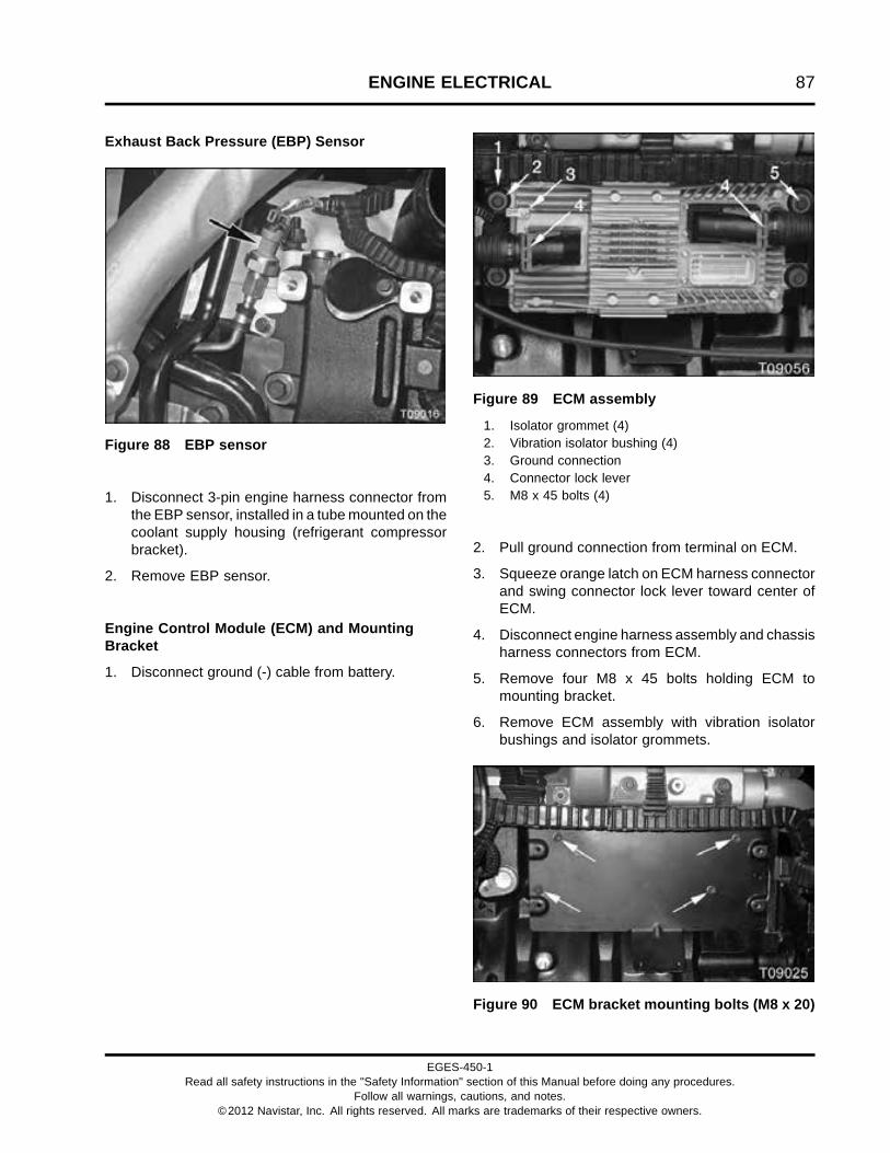
ENGINE ELECTRICAL 87
Exhaust Back Pressure (EBP) Sensor
Figure 88 EBP sensor
1. Disconnect 3-pin engine harness connector fromthe EBP sensor, installed in a tube mounted on thecoolant supply housing (refrigerant compressorbracket).
2. Remove EBP sensor.
Engine Control Module (ECM) and MountingBracket
1. Disconnect ground (-) cable from battery.
Figure 89 ECM assembly
1. Isolator grommet (4)2. Vibration isolator bushing (4)3. Ground connection4. Connector lock lever5. M8 x 45 bolts (4)
2. Pull ground connection from terminal on ECM.
3. Squeeze orange latch on ECM harness connectorand swing connector lock lever toward center ofECM.
4. Disconnect engine harness assembly and chassisharness connectors from ECM.
5. Remove four M8 x 45 bolts holding ECM tomounting bracket.
6. Remove ECM assembly with vibration isolatorbushings and isolator grommets.
Figure 90 ECM bracket mounting bolts (M8 x 20)
EGES-450-1Read all safety instructions in the "Safety Information" section of this Manual before doing any procedures.
Follow all warnings, cautions, and notes.©2012 Navistar, Inc. All rights reserved. All marks are trademarks of their respective owners.

88 ENGINE ELECTRICAL
7. Remove four M8 x 20 bolts holding ECM bracketto crankcase and remove bracket assembly.
Engine Coolant Temperature 1 (ECT1) Sensor
Figure 91 ECT1 sensor
1. Place a coolant drain pan under the engine.
2. Pull lock tab up to unlock connector.
3. Press the release tab and disconnect 2-pinengine harness connector from the ECT1 sensor,installed in the coolant supply housing (refrigerantcompressor bracket).
4. Remove ECT1 sensor.
5. Discard sensor O-ring.
6. Recycle or dispose of coolant according toapplicable regulations.
Electric Fuel Pump Connector
See Brushless Electric Fuel Pump Assembly (page194) for removal procedure.
Figure 92 Electric fuel pump connector
1. Pull lock tab out to unlock connector.
2. Press the release tab and disconnect 2-pin engineharness connector from the electric fuel pump.
Fuel Delivery Pressure (FDP) Sensor
Figure 93 FDP sensor (typical)
1. Disconnect 3-pin engine harness connector fromthe FDP sensor.
2. Remove FDP sensor from fuel filter assembly.
3. Discard sensor O-ring.
EGES-450-1Read all safety instructions in the "Safety Information" section of this Manual before doing any procedures.
Follow all warnings, cautions, and notes.©2012 Navistar, Inc. All rights reserved. All marks are trademarks of their respective owners.
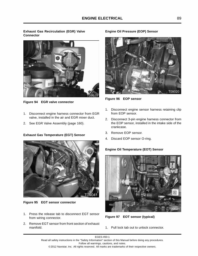
ENGINE ELECTRICAL 89
Exhaust Gas Recirculation (EGR) ValveConnector
Figure 94 EGR valve connector
1. Disconnect engine harness connector from EGRvalve, installed in the air and EGR mixer duct.
2. See EGR Valve Assembly (page 160).
Exhaust Gas Temperature (EGT) Sensor
Figure 95 EGT sensor connector
1. Press the release tab to disconnect EGT sensorfrom wiring connector.
2. Remove EGT sensor from front section of exhaustmanifold.
Engine Oil Pressure (EOP) Sensor
Figure 96 EOP sensor
1. Disconnect engine sensor harness retaining clipfrom EOP sensor.
2. Disconnect 3-pin engine harness connector fromthe EOP sensor, installed in the intake side of thecrankcase.
3. Remove EOP sensor.
4. Discard EOP sensor O-ring.
Engine Oil Temperature (EOT) Sensor
Figure 97 EOT sensor (typical)
1. Pull lock tab out to unlock connector.
EGES-450-1Read all safety instructions in the "Safety Information" section of this Manual before doing any procedures.
Follow all warnings, cautions, and notes.©2012 Navistar, Inc. All rights reserved. All marks are trademarks of their respective owners.
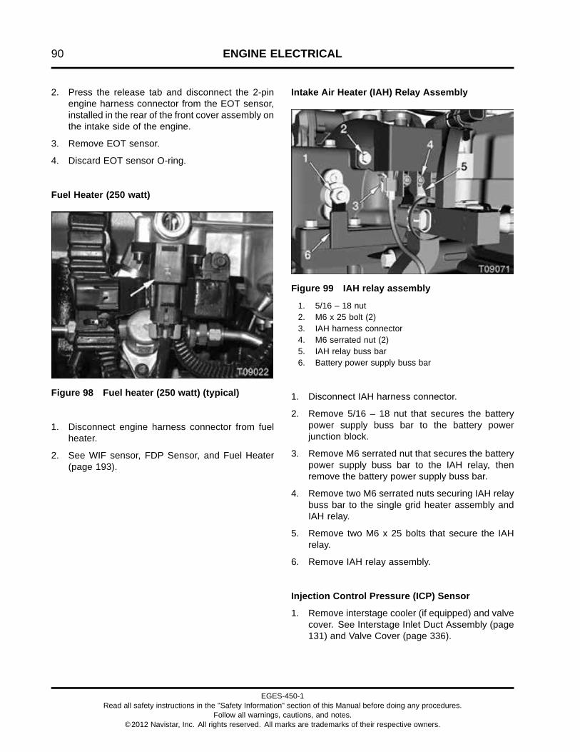
90 ENGINE ELECTRICAL
2. Press the release tab and disconnect the 2-pinengine harness connector from the EOT sensor,installed in the rear of the front cover assembly onthe intake side of the engine.
3. Remove EOT sensor.
4. Discard EOT sensor O-ring.
Fuel Heater (250 watt)
Figure 98 Fuel heater (250 watt) (typical)
1. Disconnect engine harness connector from fuelheater.
2. See WIF sensor, FDP Sensor, and Fuel Heater(page 193).
Intake Air Heater (IAH) Relay Assembly
Figure 99 IAH relay assembly
1. 5/16 – 18 nut2. M6 x 25 bolt (2)3. IAH harness connector4. M6 serrated nut (2)5. IAH relay buss bar6. Battery power supply buss bar
1. Disconnect IAH harness connector.
2. Remove 5/16 – 18 nut that secures the batterypower supply buss bar to the battery powerjunction block.
3. Remove M6 serrated nut that secures the batterypower supply buss bar to the IAH relay, thenremove the battery power supply buss bar.
4. Remove two M6 serrated nuts securing IAH relaybuss bar to the single grid heater assembly andIAH relay.
5. Remove two M6 x 25 bolts that secure the IAHrelay.
6. Remove IAH relay assembly.
Injection Control Pressure (ICP) Sensor
1. Remove interstage cooler (if equipped) and valvecover. See Interstage Inlet Duct Assembly (page131) and Valve Cover (page 336).
EGES-450-1Read all safety instructions in the "Safety Information" section of this Manual before doing any procedures.
Follow all warnings, cautions, and notes.©2012 Navistar, Inc. All rights reserved. All marks are trademarks of their respective owners.

ENGINE ELECTRICAL 91
Figure 100 ICP sensor
1. ICP sensor connector2. Valve cover gasket harness connector3. ICP sensor
2. Disconnect 3-pin valve cover gasket harnessconnector from the ICP sensor, installed in thehigh-pressure oil manifold rear of cylinder 5 fuelinjector.
3. Remove ICP sensor.
4. Discard sensor O-ring.
Engine Throttle Valve (ETV) Assembly Connector
Figure 101 ETV assembly connector
1. Pull out locking tab.
2. Push release tab and disconnect engine harnessconnector from ETV assembly, installed on theintake side of the engine.
3. See Engine Throttle Valve (ETV) Assembly (page160).
Injection Pressure Regulator (IPR) ValveConnector
Figure 102 IPR valve
1. Wire lock clip2. IPR valve connector
1. Swing wire lock clip downwards to unlock.
2. Pull connector to disconnect from IPR valve,installed in the rear of the high-pressure oil pumpon the intake side of the engine.
3. For IPR valve removal, see High-pressure OilPump Assembly and Injection Pressure Regulator(IPR) Valve Assembly (page 198).
EGES-450-1Read all safety instructions in the "Safety Information" section of this Manual before doing any procedures.
Follow all warnings, cautions, and notes.©2012 Navistar, Inc. All rights reserved. All marks are trademarks of their respective owners.

92 ENGINE ELECTRICAL
Intake Manifold Pressure (IMP) Sensor
Figure 103 IMP sensor
1. Push release tab and disconnect 3-pin engineharness connector from IMP sensor.
2. Remove IMP sensor.
3. Discard IMP sensor O-rings.
Intake Manifold Temperature (IMT) Sensor
Figure 104 IMT sensor
1. Pull up IMT sensor locking tab.
2. Push release tab and disconnect 2-pin engineharness connector from IMT sensor.
3. Remove IMT sensor.
4. Discard IMT sensor O-rings.
Downstream Injection (DSI) AssemblyConnectors
Figure 105 DSI assembly
1. Upstream pressure/temperature sensor connector2. Tie strap3. Dosing Valve (DV) connector4. Downstream pressure sensor5. Yellow connector lock6. Shutoff Valve (SV)
1. Pull out the yellow connector lock and thendisconnect engine harness connectors for theUpstream pressure/temperature sensor, DV,downstream pressure sensor and SV.
2. Remove engine harness from DSI assembly.
3. For DSI assembly removal, see Down StreamInjection (DSI) Assembly (page 115).
EGES-450-1Read all safety instructions in the "Safety Information" section of this Manual before doing any procedures.
Follow all warnings, cautions, and notes.©2012 Navistar, Inc. All rights reserved. All marks are trademarks of their respective owners.

ENGINE ELECTRICAL 93
Water In Fuel (WIF) Sensor
Figure 106 WIF sensor
1. Disconnect engine harness connector from theWIF sensor.
2. Remove WIF sensor.
3. Discard sensor O-ring.
EGES-450-1Read all safety instructions in the "Safety Information" section of this Manual before doing any procedures.
Follow all warnings, cautions, and notes.©2012 Navistar, Inc. All rights reserved. All marks are trademarks of their respective owners.

94 ENGINE ELECTRICAL
Engine Harness Assembly
1. Disconnect the battery ground (-) cable.
Figure 107 Engine wiring harness connection points – intake side
1. Tie strap (3)2. Exhaust brake valve assembly
connector
3. Valve cover gasket connector (4)4. M10 nut (2)5. 16-pin interconnect
6. M8 nut (2)7. Electro Magnetic Interference
(EMI) ground connection
2. Squeeze orange latch on ECM harness connectorand lift lever to unlock connectors.
3. Disconnect engine harness assembly and chassisharness connectors from ECM and disconnectEMI ground connection.
4. Disconnect engine harness assembly connectorsfrom sensors and actuators on intake side ofengine.
5. Remove two M10 nuts.
6. Cut three tie straps.
7. Remove Engine Harness Assembly from fourvalve cover gasket connectors.
8. Remove M6 x 16 bolt securing the 16-pininterconnect.
9. Remove two M8 nuts.
EGES-450-1Read all safety instructions in the "Safety Information" section of this Manual before doing any procedures.
Follow all warnings, cautions, and notes.©2012 Navistar, Inc. All rights reserved. All marks are trademarks of their respective owners.

ENGINE ELECTRICAL 95
Figure 108 Engine wiring harness connectionpoints – front top view (M8 x 12 bolt)
10. Remove M8 x 12 bolt.
Figure 109 Engine wiring harness connectionpoints – exhaust side
1. Coolant supply housing2. Tie strap with fir zip harness retainer (3)
11. Cut tie straps on fir zip harness retainers.
12. Disconnect connectors from ECT1 sensor, EGTsensor and TC2WC valve.
13. Remove engine wiring harness from coolantsupply housing.
14. Remove Engine Harness assembly from theengine.
EGES-450-1Read all safety instructions in the "Safety Information" section of this Manual before doing any procedures.
Follow all warnings, cautions, and notes.©2012 Navistar, Inc. All rights reserved. All marks are trademarks of their respective owners.

96 ENGINE ELECTRICAL
Valve Cover Gasket Assembly
1. Remove interstage cooler and valve cover. SeeInterstage Cooler (ISC) (page 132) and ValveCover (page 336).
Figure 110 Valve cover gasket assembly connectors
1. Injector 1 harness connector2. ECBP sensor connector3. Injector 2 harness connector4. Injector 3 harness connector
5. ECB valve connector6. Injector 4 harness connector7. Injector 5 harness connector8. Injector 6 harness connector
9. ICP sensor connector10. Valve cover gasket connector (4)
2. Disconnect four valve cover gasket connectors,ICP sensor connector, and six injector harnessconnectors.
3. Disconnect ECBP sensor connector and ECBvalve connector.
4. Starting at one side, lightly pry up and open eachof the six wire channel retainers while gentlypulling up to remove valve cover gasket harnessfrom engine.
EGES-450-1Read all safety instructions in the "Safety Information" section of this Manual before doing any procedures.
Follow all warnings, cautions, and notes.©2012 Navistar, Inc. All rights reserved. All marks are trademarks of their respective owners.

ENGINE ELECTRICAL 97
InspectInspect Wiring Harness, Connectors, andElectrical Components
1. Inspect each wiring harness for corrosion (green,gray, or white deposits), female connector sleevesthat are spread open, and terminal pins that arepushed back relative to the other terminals inthe same connector. Clean, repair, or replaceconnectors and terminals if necessary.
2. Inspect wire harness near sensors and actuatorsfor damage due to sharp bends; see diagnosticmanual for continuous monitor testing.
3. Inspect each wiring harness for wear and heatdamage to wiring and connectors. Repair orreplace if necessary.
4. Replace any broken harness connection pointsand zip ties.
5. Check for damage caused by zip ties that are tootight.
6. Inspect connector pins on all electricalcomponents. If any pins are bent or pushed in,repair or replace component.
7. Inspect female connector terminals for spreading.
8. Inspect electrical sensors, actuators, and valvesfor cracks and damage. Replace damagedcomponents if necessary.
9. Inspect pressure sensors for soot, sludge, debris,or other contamination. Clean or replace asneeded.
NOTE: See EGES-455 Engine Diagnostic Manualfor further inspection and repair of engine electricalcomponents and systems.
EGES-450-1Read all safety instructions in the "Safety Information" section of this Manual before doing any procedures.
Follow all warnings, cautions, and notes.©2012 Navistar, Inc. All rights reserved. All marks are trademarks of their respective owners.
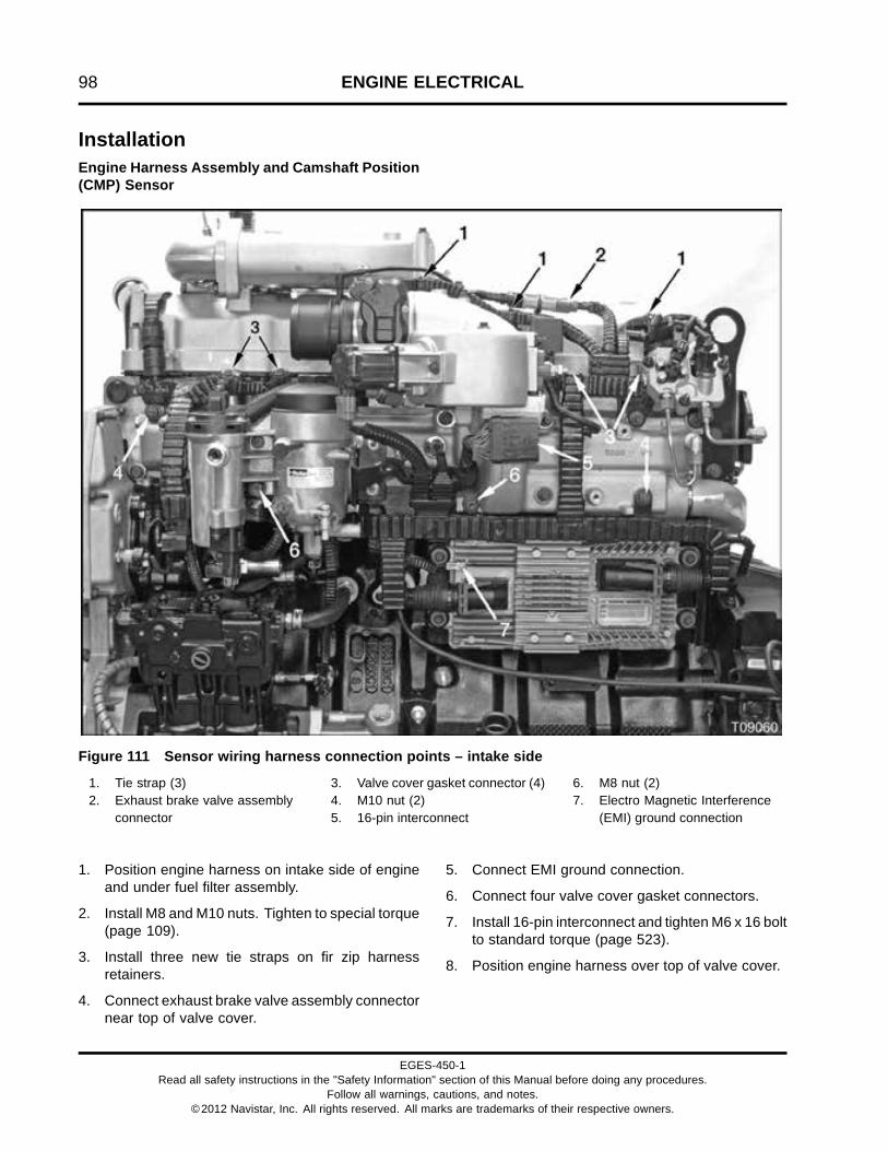
98 ENGINE ELECTRICAL
InstallationEngine Harness Assembly and Camshaft Position(CMP) Sensor
Figure 111 Sensor wiring harness connection points – intake side
1. Tie strap (3)2. Exhaust brake valve assembly
connector
3. Valve cover gasket connector (4)4. M10 nut (2)5. 16-pin interconnect
6. M8 nut (2)7. Electro Magnetic Interference
(EMI) ground connection
1. Position engine harness on intake side of engineand under fuel filter assembly.
2. Install M8 and M10 nuts. Tighten to special torque(page 109).
3. Install three new tie straps on fir zip harnessretainers.
4. Connect exhaust brake valve assembly connectornear top of valve cover.
5. Connect EMI ground connection.
6. Connect four valve cover gasket connectors.
7. Install 16-pin interconnect and tighten M6 x 16 boltto standard torque (page 523).
8. Position engine harness over top of valve cover.
EGES-450-1Read all safety instructions in the "Safety Information" section of this Manual before doing any procedures.
Follow all warnings, cautions, and notes.©2012 Navistar, Inc. All rights reserved. All marks are trademarks of their respective owners.

ENGINE ELECTRICAL 99
Figure 112 Sensor wiring harness connectionpoints – front top view (M8 x 12 bolt)
9. Install M8 x 12 bolt to secure wiring harness tovalve cover. Tighten to special torque (page 109).
Figure 113 CMP sensor
1. M8 x 20 bolt2. Engine harness bracket3. CMP sensor4. CMP sensor connector5. M6 x 16 sensor retaining bolt
10. Slide engine harness bracket behind fan pulley.Install M8 x 20 engine harness bracket bolt andtighten to standard torque (page 523).
11. Connect CMP sensor connector to CMP sensor.
Figure 114 Engine harness connection points –exhaust side
1. Coolant supply housing2. Tie strap with fir zip harness retainer (3)
12. Weave engine harness around casting featureson coolant supply housing.
13. Secure engine harness to fir zip harness retainerswith new tie straps.
14. Insert fir zip connector into interstage cooler inletpipe.
EGES-450-1Read all safety instructions in the "Safety Information" section of this Manual before doing any procedures.
Follow all warnings, cautions, and notes.©2012 Navistar, Inc. All rights reserved. All marks are trademarks of their respective owners.

100 ENGINE ELECTRICAL
Boost Control Harness Assembly andTurbocharger 2 Wastegate Control (TC2WC) Valve
Figure 115 Boost control harness assembly andTC2WC valve
1. Turbocharger wastegate actuatorconnector—vacuum line
2. Connector wire clip lock3. Turbocharger 2 Wastegate Control (TC2WC) valve
2-pin connector4. M5 x 16 socket head bolt (2)5. Insulator—high temperature plastic (2)6. Exhaust Gas Temperature (EGT) connector7. Interstage Cooler (ISC) inlet duct8. Exhaust Gas Temperature (EGT) sensor9. Turbocharger air inlet duct connector—vacuum line
1. Install TC2WC valve on ISC inlet duct with two M5x 16 socket head bolts and two new insulators.Make sure insulators are placed on bolts betweenTC2WC valve and ISC inlet duct. Tighten bolts tostandard torque (page 523).
2. Install a new boost control harness assembly(vacuum lines) to turbocharger wastegateactuator connector, turbocharger air inlet ductconnector, TC2WC valve, and throttle coupling.Crimp clamps at throttle coupling and TC2WCvalve.
3. Connect TC2WC 2-pin connector to TC2WCvalve and push in connector wire clip lock.
Crankshaft Position (CKP) Sensor
Figure 116 CKP sensor
1. M6 x 16 sensor retaining bolt2. CKP 2-pin connector
1. Lubricate new O-rings with clean engine oil andinstall on CKP sensor.
2. Install CKP sensor into the flywheel housing.
3. Install M6 x 16 retaining bolt and tighten tostandard torque (page 523).
4. Connect engine harness connector to CKPsensor.
EGES-450-1Read all safety instructions in the "Safety Information" section of this Manual before doing any procedures.
Follow all warnings, cautions, and notes.©2012 Navistar, Inc. All rights reserved. All marks are trademarks of their respective owners.
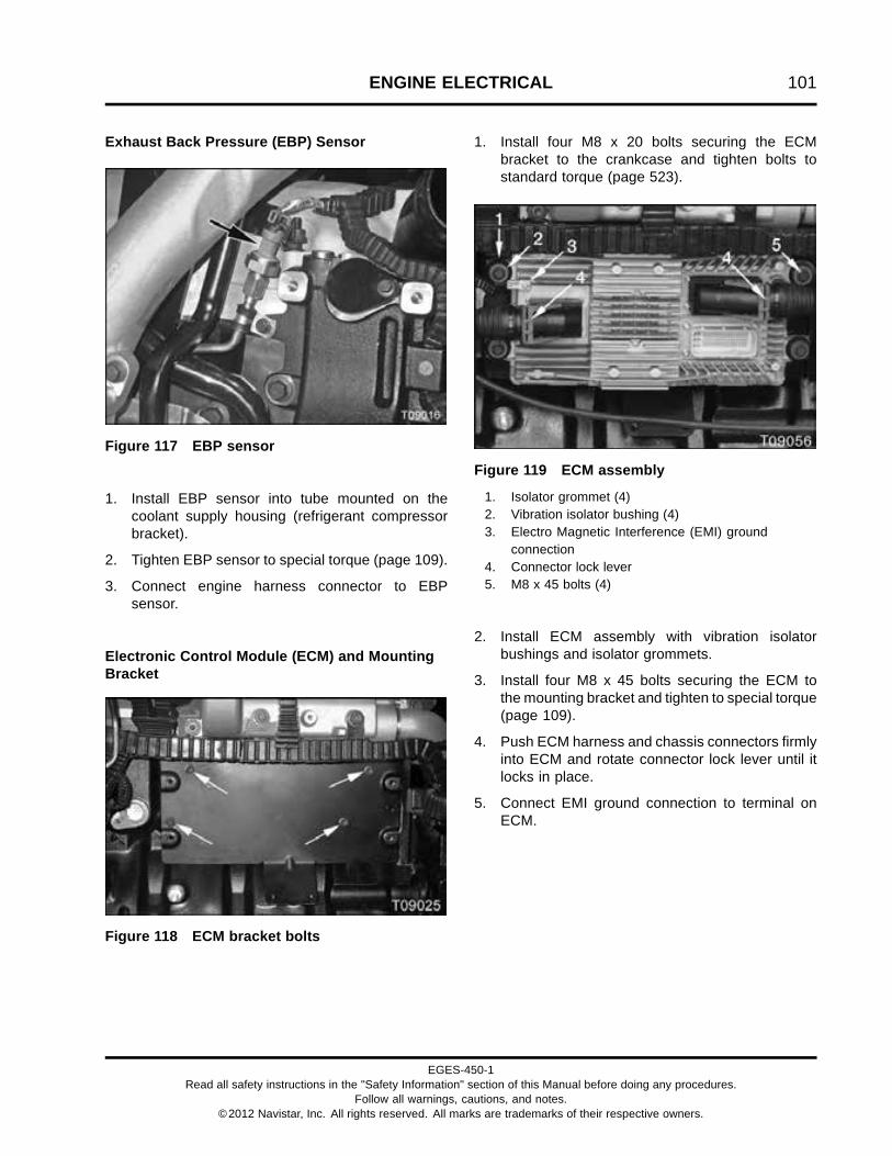
ENGINE ELECTRICAL 101
Exhaust Back Pressure (EBP) Sensor
Figure 117 EBP sensor
1. Install EBP sensor into tube mounted on thecoolant supply housing (refrigerant compressorbracket).
2. Tighten EBP sensor to special torque (page 109).
3. Connect engine harness connector to EBPsensor.
Electronic Control Module (ECM) and MountingBracket
Figure 118 ECM bracket bolts
1. Install four M8 x 20 bolts securing the ECMbracket to the crankcase and tighten bolts tostandard torque (page 523).
Figure 119 ECM assembly
1. Isolator grommet (4)2. Vibration isolator bushing (4)3. Electro Magnetic Interference (EMI) ground
connection4. Connector lock lever5. M8 x 45 bolts (4)
2. Install ECM assembly with vibration isolatorbushings and isolator grommets.
3. Install four M8 x 45 bolts securing the ECM tothe mounting bracket and tighten to special torque(page 109).
4. Push ECM harness and chassis connectors firmlyinto ECM and rotate connector lock lever until itlocks in place.
5. Connect EMI ground connection to terminal onECM.
EGES-450-1Read all safety instructions in the "Safety Information" section of this Manual before doing any procedures.
Follow all warnings, cautions, and notes.©2012 Navistar, Inc. All rights reserved. All marks are trademarks of their respective owners.

102 ENGINE ELECTRICAL
Engine Coolant Temperature 1 (ECT1) Sensor
Figure 120 ECT1 sensor
1. Install a new O-ring on ECT1 sensor.
2. Install ECT1 sensor into the coolant supplyhousing (refrigerant compressor bracket) andtighten to special torque (page 109).
3. Connect engine harness connector to ECT1sensor.
4. Push lock tab down to lock connector.
Fuel Delivery Pressure (FDP) Sensor
Figure 121 FDP sensor (typical)
1. Install new O-ring on FDP sensor
2. Install FDP sensor and tighten to special torque(page 109).
3. Connect 3-pin engine harness connector to theFDP sensor.
Exhaust Gas Recirculation (EGR) Control ValveConnector
1. See EGR Valve Assembly (page 166) for EGRcontrol valve installation.
Figure 122 EGR valve connector
2. Connect engine harness connector to the EGRvalve.
Electric Fuel Pump Connector
Figure 123 Electric fuel pump connector
EGES-450-1Read all safety instructions in the "Safety Information" section of this Manual before doing any procedures.
Follow all warnings, cautions, and notes.©2012 Navistar, Inc. All rights reserved. All marks are trademarks of their respective owners.

ENGINE ELECTRICAL 103
1. Connect engine harness connector to electric fuelpump.
2. Push lock tab into lock connector.
Exhaust Gas Temperature (EGT) Sensor
Figure 124 EGT sensor connector
1. Install EGT sensor and tighten to special torque(page 109).
2. Connect engine harness connector to the EGTsensor.
Engine Oil Pressure (EOP) Sensor
Figure 125 EOP sensor
1. Lubricate a new O-ring with clean engine oil andinstall on EOP sensor.
2. Install EOP sensor into the intake side of thecrankcase and tighten to special torque (page109).
3. Connect engine harness connector to EOPsensor.
4. Connect engine sensor harness retaining clip toEOP sensor.
Engine Oil Temperature (EOT) Sensor
Figure 126 EOT sensor
1. Lubricate a new O-ring with clean engine oil andinstall on EOT sensor.
2. Install EOT sensor into the back of the front coverand tighten to special torque (page 109).
3. Connect engine harness connector to the EOTsensor.
4. Push lock tab down to lock connector.
Fuel Heater (250 watt) Connector
1. See Water In Fuel (WIF) Sensor, Fuel DeliveryPressure (FDP) Sensor, and 250 Watt Fuel Heater(page 193) for 250 Watt Fuel Heater installation.
EGES-450-1Read all safety instructions in the "Safety Information" section of this Manual before doing any procedures.
Follow all warnings, cautions, and notes.©2012 Navistar, Inc. All rights reserved. All marks are trademarks of their respective owners.

104 ENGINE ELECTRICAL
Figure 127 Fuel heater (250 watt) (typical)
2. Connect engine harness connector to 250 wattfuel heater.
Intake Air Heater (IAH) Relay Assembly
Figure 128 IAH relay assembly
1. 5/16 – 18 nut2. M6 x 25 bolt (2)3. IAH harness connector4. M6 serrated nut (2)5. IAH relay buss bar6. Battery power supply buss bar
1. Install two M6 x 25 bolts. Tighten bolts to standardtorque (page 523).
2. Install IAH relay buss bar on single grid heaterstud and secure with two M6 serrated nuts.Tighten nut to special torque (page 109).
3. Install the battery power supply buss bar on 5/16and M6 studs. Tighten 5/16 – 18 nut and M6serrated nut to special torque (page 109).
4. Connect IAH harness connector to IAH relayassembly.
Injector Control Pressure (ICP) Sensor
Figure 129 ICP sensor
1. ICP sensor connector2. Valve cover gasket harness connector3. ICP sensor
1. Lubricate a new O-ring with clean engine oil andinstall on the ICP sensor.
2. Install ICP sensor into high-pressure oil manifold,to the rear of cylinder 5 fuel injector, and tightento special torque (page 109).
3. Connect valve cover gasket harness connector tothe ICP sensor connector.
EGES-450-1Read all safety instructions in the "Safety Information" section of this Manual before doing any procedures.
Follow all warnings, cautions, and notes.©2012 Navistar, Inc. All rights reserved. All marks are trademarks of their respective owners.

ENGINE ELECTRICAL 105
Engine Throttle Valve (ETV) Assembly Connector
1. See Engine Throttle Valve (ETV) Assembly (page166) for ETV installation.
Figure 130 ETV assembly engine harnessconnector
2. Connect engine harness connector to ETVassembly.
3. Push down locking tab to lock engine harnessconnector.
Injection Pressure Regulator (IPR) ValveConnector
1. See High-pressure Oil Pump Assembly andInjection Pressure Regulator (IPR) ValveAssembly (page 207) for IPR valve installation.
Figure 131 IPR valve on high-pressure oil pump(typical)
1. Wire clip lock2. IPR valve connector
2. Connect IPR valve connector to IPR valve.
3. Connect engine harness wire clip lock.
4. Secure wire clip with a Zip tie.
Intake Manifold Temperature (IMT) Sensor
Figure 132 IMT sensor
1. Install a new O-ring on the IMT sensor.
2. Install IMT sensor into the intake manifold andtighten to special torque (page 109).
EGES-450-1Read all safety instructions in the "Safety Information" section of this Manual before doing any procedures.
Follow all warnings, cautions, and notes.©2012 Navistar, Inc. All rights reserved. All marks are trademarks of their respective owners.

106 ENGINE ELECTRICAL
3. Connect engine harness connectors to the IMTsensor.
4. Push down IMT sensor locking tab to lock engineharness connector.
Intake Manifold Pressure (IMP) Sensor
Figure 133 IMP sensor
1. Install a new O-ring on the IMP sensor.
2. Install IMP sensor into the intake manifold andtighten to special torque (page 109).
3. Connect engine harness connectors to the IMPsensor.
Downstream Injection (DSI) AssemblyConnectors
1. Install DSI assembly. See Down Stream Injection(DSI) Assembly (page 120).
Figure 134 DSI assembly
1. Upstream pressure/temperature sensor connector2. Tie strap3. Dosing Valve (DV) connector4. Downstream pressure sensor connector5. Shutoff Valve (SV) connector6. Shutoff Valve (SV)
2. Connect engine harness connectors to Upstreampressure/temperature sensor, DV, downstreampressure sensor and SV.
3. Push in the yellow connector lock to secureconnector.
EGES-450-1Read all safety instructions in the "Safety Information" section of this Manual before doing any procedures.
Follow all warnings, cautions, and notes.©2012 Navistar, Inc. All rights reserved. All marks are trademarks of their respective owners.
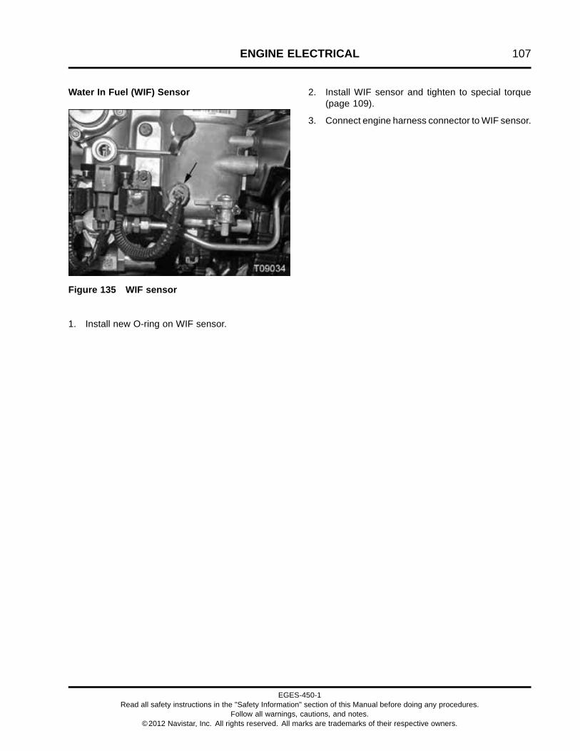
ENGINE ELECTRICAL 107
Water In Fuel (WIF) Sensor
Figure 135 WIF sensor
1. Install new O-ring on WIF sensor.
2. Install WIF sensor and tighten to special torque(page 109).
3. Connect engine harness connector to WIF sensor.
EGES-450-1Read all safety instructions in the "Safety Information" section of this Manual before doing any procedures.
Follow all warnings, cautions, and notes.©2012 Navistar, Inc. All rights reserved. All marks are trademarks of their respective owners.

108 ENGINE ELECTRICAL
Valve Cover Gasket Assembly
Figure 136 Valve cover gasket assembly connectors
1. Injector 1 harness connector2. ECBP sensor connector3. Injector 2 harness connector4. Injector 3 harness connector
5. ECB valve connector6. Injector 4 harness connector7. Injector 5 harness connector8. Injector 6 harness connector
9. ICP sensor connector10. Valve cover gasket connector (4)
1. Position valve cover gasket harness on cylinderhead and carefully push down each of the sixwire channel retainers to snap harness ontohigh-pressure oil manifold.
2. Connect four valve cover gasket connectors,ICP sensor connector, and six injector harnessconnectors.
3. If equipped, connect ECB valve and ECBP sensorconnectors.
EGES-450-1Read all safety instructions in the "Safety Information" section of this Manual before doing any procedures.
Follow all warnings, cautions, and notes.©2012 Navistar, Inc. All rights reserved. All marks are trademarks of their respective owners.

ENGINE ELECTRICAL 109
Special Torque
Battery power junction block, 5/16 – 18 nut 17 N·m (12 lbf·ft)
Exhaust Back Pressure (EBP) sensor 20 N·m (15 lbf·ft)
Engine Control Module (ECM) mounting bolts, M8 x 45 31 N·m (23 lbf·ft)
Engine Coolant Temperature 1 (ECT1) sensor 17.5 N·m (154 lbf·in)
Fuel Delivery Pressure (FDP) sensor 12 N·m (102 lbf·in)
Exhaust Gas Temperature (EGT) sensor 44 N·m (32 lbf·ft)
Engine harness M8 x 12 bolt 34 N·m (25 lbf·ft)
Engine harness M8 and M10 nuts 34 N·m (25 lbf·ft)
Engine Oil Pressure (EOP) sensor 11.5 N·m (101 lbf·in)
Engine Oil Temperature (EOT) sensor 17.5 N·m (154 lbf·in)
Intake Air Heater (IAH) relay M6 serrated nuts 4 N·m (35 lbf·in)
Injection Control Pressure (ICP) sensor 18 N·m (162 lbf·in)
Intake Manifold Pressure (IMP) sensor 11.5 N·m (101 lbf·in)
Intake Manifold Temperature (IMT) sensor 10.5 N·m (93 lbf·in)
Water In Fuel (WIF) sensor 2 N·m (15 lbf·in)
EGES-450-1Read all safety instructions in the "Safety Information" section of this Manual before doing any procedures.
Follow all warnings, cautions, and notes.©2012 Navistar, Inc. All rights reserved. All marks are trademarks of their respective owners.

110 ENGINE ELECTRICAL
EGES-450-1Read all safety instructions in the "Safety Information" section of this Manual before doing any procedures.
Follow all warnings, cautions, and notes.©2012 Navistar, Inc. All rights reserved. All marks are trademarks of their respective owners.

DOWN STREAM INJECTION (DSI) & RELATED COMPONENTS 111
Table of Contents
Exploded Views.. . . . . . . . . . . . . . . . . . . . . . . . . . . . . . . . . . . . . . . . . . . . . . . . . . . . . . . . . . . . . . . . . . . . . . . . . . . . . . . . . . . . . . . . . . . . . . . . . . . . . . .113Down Stream Injection (DSI) Assembly. . . . . . . . . . . . . . . . . . . . . . . . . . . . . . . . . . . . . . . . . . . . . . . . . . . . . . . . . . . . . . . . . .113Hydrocarbon Injector Assembly. . . . . . . . . . . . . . . . . . . . . . . . . . . . . . . . . . . . . . . . . . . . . . . . . . . . . . . . . . . . . . . . . . . . . . . . . . .114
Removal. . . . . . . . . . . . . . . . . . . . . . . . . . . . . . . . . . . . . . . . . . . . . . . . . . . . . . . . . . . . . . . . . . . . . . . . . . . . . . . . . . . . . . . . . . . . . . . . . . . . . . . . . . . . . . . . . .115Down Stream Injection (DSI) Assembly. . . . . . . . . . . . . . . . . . . . . . . . . . . . . . . . . . . . . . . . . . . . . . . . . . . . . . . . . . . . . . . . . .115Injection Unit Inlet Tube Assembly. . . . . . . . . . . . . . . . . . . . . . . . . . . . . . . . . . . . . . . . . . . . . . . . . . . . . . . . . . . . . . . . . . . . . . . .116Hydrocarbon Injector Assembly. . . . . . . . . . . . . . . . . . . . . . . . . . . . . . . . . . . . . . . . . . . . . . . . . . . . . . . . . . . . . . . . . . . . . . . . . . .117
Installation. . . . . . . . . . . . . . . . . . . . . . . . . . . . . . . . . . . . . . . . . . . . . . . . . . . . . . . . . . . . . . . . . . . . . . . . . . . . . . . . . . . . . . . . . . . . . . . . . . . . . . . . . . . . . . .119Hydrocarbon Injector Assembly. . . . . . . . . . . . . . . . . . . . . . . . . . . . . . . . . . . . . . . . . . . . . . . . . . . . . . . . . . . . . . . . . . . . . . . . . . .119Injection Unit Inlet Tube Assembly. . . . . . . . . . . . . . . . . . . . . . . . . . . . . . . . . . . . . . . . . . . . . . . . . . . . . . . . . . . . . . . . . . . . . . . .120Down Stream Injection (DSI) Assembly. . . . . . . . . . . . . . . . . . . . . . . . . . . . . . . . . . . . . . . . . . . . . . . . . . . . . . . . . . . . . . . . . .120
Special Torque.. . . . . . . . . . . . . . . . . . . . . . . . . . . . . . . . . . . . . . . . . . . . . . . . . . . . . . . . . . . . . . . . . . . . . . . . . . . . . . . . . . . . . . . . . . . . . . . . . . . . . . . . .123
EGES-450-1Read all safety instructions in the "Safety Information" section of this Manual before doing any procedures.
Follow all warnings, cautions, and notes.©2012 Navistar, Inc. All rights reserved. All marks are trademarks of their respective owners.

112 DOWN STREAM INJECTION (DSI) & RELATED COMPONENTS
EGES-450-1Read all safety instructions in the "Safety Information" section of this Manual before doing any procedures.
Follow all warnings, cautions, and notes.©2012 Navistar, Inc. All rights reserved. All marks are trademarks of their respective owners.

DOWN STREAM INJECTION (DSI) & RELATED COMPONENTS 113
Exploded ViewsDown Stream Injection (DSI) Assembly
Figure 137 Down Stream Injection (DSI) assembly
1. M8 nut (3)2. Down Stream Injection (DSI)
assembly3. Down Stream Injection (DSI)
support4. M10 nut (2)5. Rubber cushioned clamp (2)
6. M6 x 12 bolt (2)7. M6 x 14 bolt8. Tube clamp (2 pcs)9. Injection unit inlet tube assembly10. 90 degree M12 tube fitting elbow11. Down Stream Injection (DSI)
inlet tube assembly (hard tube)
12. Fitting assembly (2)13. O-ring seal (2)14. Down Stream Injection (DSI)
inlet tube assembly (flexibletube)
EGES-450-1Read all safety instructions in the "Safety Information" section of this Manual before doing any procedures.
Follow all warnings, cautions, and notes.©2012 Navistar, Inc. All rights reserved. All marks are trademarks of their respective owners.

114 DOWN STREAM INJECTION (DSI) & RELATED COMPONENTS
Hydrocarbon Injector Assembly
Figure 138 Hydrocarbon injector assembly
1. M8 x 45 bolt (2)2. Hydrocarbon injector assembly3. Hydrocarbon injector gasket
4. Injector coolant inlet tubeassembly
5. Injector coolant outlet tubeassembly
6. Tube fitting (90 degree elbow)7. M10 37 degree flare fitting
EGES-450-1Read all safety instructions in the "Safety Information" section of this Manual before doing any procedures.
Follow all warnings, cautions, and notes.©2012 Navistar, Inc. All rights reserved. All marks are trademarks of their respective owners.
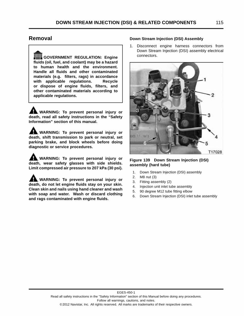
DOWN STREAM INJECTION (DSI) & RELATED COMPONENTS 115
Removal
GOVERNMENT REGULATION: Enginefluids (oil, fuel, and coolant) may be a hazardto human health and the environment.Handle all fluids and other contaminatedmaterials (e.g. filters, rags) in accordancewith applicable regulations. Recycleor dispose of engine fluids, filters, andother contaminated materials according toapplicable regulations.
WARNING: To prevent personal injury ordeath, read all safety instructions in the “SafetyInformation” section of this manual.
WARNING: To prevent personal injury ordeath, shift transmission to park or neutral, setparking brake, and block wheels before doingdiagnostic or service procedures.
WARNING: To prevent personal injury ordeath, wear safety glasses with side shields.Limit compressed air pressure to 207 kPa (30 psi).
WARNING: To prevent personal injury ordeath, do not let engine fluids stay on your skin.Clean skin and nails using hand cleaner and washwith soap and water. Wash or discard clothingand rags contaminated with engine fluids.
Down Stream Injection (DSI) Assembly
1. Disconnect engine harness connectors fromDown Stream Injection (DSI) assembly electricalconnectors.
Figure 139 Down Stream Injection (DSI)assembly (hard tube)
1. Down Stream Injection (DSI) assembly2. M8 nut (3)3. Fitting assembly (2)4. Injection unit inlet tube assembly5. 90 degree M12 tube fitting elbow6. Down Stream Injection (DSI) inlet tube assembly
EGES-450-1Read all safety instructions in the "Safety Information" section of this Manual before doing any procedures.
Follow all warnings, cautions, and notes.©2012 Navistar, Inc. All rights reserved. All marks are trademarks of their respective owners.

116 DOWN STREAM INJECTION (DSI) & RELATED COMPONENTS
Figure 140 Down Stream Injection (DSI)assembly (flexible tube)
1. Down Stream Injection (DSI) assembly2. M8 nut (3)3. Fitting assembly (2)4. Injection unit inlet tube assembly5. 90 degree M12 tube fitting elbow6. Down Stream Injection (DSI) inlet tube assembly
WARNING: To prevent personal injury ordeath, do not smoke and keep fuel away fromflames and sparks.
2. Using line wrenches, disconnect Down StreamInjection (DSI) inlet tube assembly and injectionunit inlet tube assembly from fitting assemblies onDown Stream Injection (DSI) assembly.
3. Remove DSI inlet tube assembly from 90 degreeM12 tube fitting elbow.
4. Remove and save three M8 nuts from DSIassembly.
5. Remove DSI assembly from DSI assemblysupport.
6. If required, remove fitting assemblies from DSIassembly and discard O-rings.
7. If required, remove 90 degree M12 tube fittingelbow from intake manifold.
Figure 141 Down Stream Injection (DSI) support
1. Down Stream Injection (DSI) support2. M10 nut (2)
8. Remove two M10 nuts from studs in cylinderhead.
9. Remove Down Stream Injection (DSI) supportfrom cylinder head.
Injection Unit Inlet Tube Assembly
WARNING: To prevent personal injury ordeath, do not smoke and keep fuel away fromflames and sparks.
EGES-450-1Read all safety instructions in the "Safety Information" section of this Manual before doing any procedures.
Follow all warnings, cautions, and notes.©2012 Navistar, Inc. All rights reserved. All marks are trademarks of their respective owners.

DOWN STREAM INJECTION (DSI) & RELATED COMPONENTS 117
Figure 142 Injection unit inlet tube assembly athydrocarbon injector
1. M6 x 12 bolts (2)2. Injection unit inlet tube assembly3. Injection unit inlet tube flare nut4. Hydrocarbon injector
1. Use a backup wrench to prevent movement ofhydrocarbon injector and disconnect injection unitinlet tube flare nut.
2. Remove two M6 x 12 bolts securing injection unitinlet tube assembly to crossover tube support oncylinder head.
3. Remove injection unit inlet tube assembly.
NOTE: The injection unit inlet tube assembly hasprecise specifications; only use proper replacementparts. Do not fabricate any fuel lines for Down StreamInjection (DSI) system.
Hydrocarbon Injector Assembly
Figure 143 Hydrocarbon injector assembly
1. M8 x 45 bolt (2)2. Hydrocarbon injector assembly3. Tube fitting (90 degree elbow)4. Injector coolant inlet tube assembly5. Injector coolant outlet tube assembly6. 37 degree flare nut (2)7. M10 37 degree flare fitting
WARNING: To prevent personal injury ordeath, do not smoke and keep fuel away fromflames and sparks.
1. Use a backup wrench to prevent movement ofM10 37 degree flare fitting while removing 37degree flare nut. Remove injector coolant outlettube 37 degree flare nut from fitting.
2. Loosen and remove injector coolant inlet tube 37degree flare nut from 90 degree elbow tube fitting.
EGES-450-1Read all safety instructions in the "Safety Information" section of this Manual before doing any procedures.
Follow all warnings, cautions, and notes.©2012 Navistar, Inc. All rights reserved. All marks are trademarks of their respective owners.

118 DOWN STREAM INJECTION (DSI) & RELATED COMPONENTS
Figure 144 Hydrocarbon injector coolant tubes
1. Injector coolant inlet tube assembly2. High fin density EGR cooler3. Injector coolant outlet tube assembly
3. Remove Injector coolant inlet tube assembly andInjector coolant outlet tube assembly from high findensity EGR cooler.
4. Remove M10 37 degree flare fitting and 90degree elbow tube fitting from hydrocarboninjector, if required.
5. Remove and discard two M8 x 45 bolts that securehydrocarbon injector assembly.
NOTE: Do not reuse M8 x 45 bolts. These bolts arespecial high temperature fasteners. Install new bolts.
6. Remove hydrocarbon injector assembly.
Figure 145 Hydrocarbon injector gasket
7. Remove and discard hydrocarbon injector gasket.
EGES-450-1Read all safety instructions in the "Safety Information" section of this Manual before doing any procedures.
Follow all warnings, cautions, and notes.©2012 Navistar, Inc. All rights reserved. All marks are trademarks of their respective owners.

DOWN STREAM INJECTION (DSI) & RELATED COMPONENTS 119
InstallationHydrocarbon Injector Assembly
Figure 146 Hydrocarbon injector gasket
1. Install a new hydrocarbon injector gasket.
Figure 147 Hydrocarbon injector unit
1. M8 x 45 bolt (2)2. Hydrocarbon injector assembly3. Tube fitting (90 degree elbow)4. Injector coolant inlet tube assembly5. Injector coolant outlet tube assembly6. 37 degree flare nut (2)7. M10 37 degree flare fitting
2. Position hydrocarbon injector assembly somounting holes align with holes in gasket.
NOTE: Do not reuse M8 x 45 bolts. These bolts arespecial high temperature fasteners. Install new bolts.
3. Install two new M8 x 45 bolts. Tighten bolts totwo-step special torque (page 123).
4. If previously removed, install M10 37 degreeflare fitting and 90 degree elbow tube fitting intohydrocarbon injector assembly. Tighten M10 37degree flare fitting to special torque (page 123).Tighten 90 degree elbow tube fitting finger tight.Back out 90 degree elbow tube fitting to allow forinstallation of Injector coolant inlet tube assembly.
NOTE: Install injector coolant inlet tube assemblyfirst, then the injector coolant outlet tube assembly.The injector coolant inlet tube assembly attaches atthe lower port (90 degree elbow tube fitting) on thehydrocarbon injector assembly. Ports are labeled “in”and “out”.
Figure 148 Hydrocarbon injector coolant tubes
1. Injector coolant inlet tube assembly2. High fin density EGR cooler3. Injector coolant outlet tube assembly
5. Connect injector coolant inlet tube assembly tohigh fin density EGR cooler and 90 degree elbowtube fitting. Tighten tube fittings finger tight.
6. Tighten 90 degree elbow tube fitting to specialtorque (page 123).
7. While maintaining injector coolant inlet tubeassembly clearance from exhaust brake housing,tighten fittings to special torque (page 123).
EGES-450-1Read all safety instructions in the "Safety Information" section of this Manual before doing any procedures.
Follow all warnings, cautions, and notes.©2012 Navistar, Inc. All rights reserved. All marks are trademarks of their respective owners.
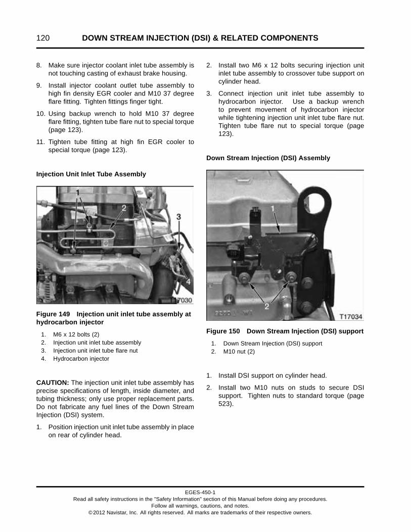
120 DOWN STREAM INJECTION (DSI) & RELATED COMPONENTS
8. Make sure injector coolant inlet tube assembly isnot touching casting of exhaust brake housing.
9. Install injector coolant outlet tube assembly tohigh fin density EGR cooler and M10 37 degreeflare fitting. Tighten fittings finger tight.
10. Using backup wrench to hold M10 37 degreeflare fitting, tighten tube flare nut to special torque(page 123).
11. Tighten tube fitting at high fin EGR cooler tospecial torque (page 123).
Injection Unit Inlet Tube Assembly
Figure 149 Injection unit inlet tube assembly athydrocarbon injector
1. M6 x 12 bolts (2)2. Injection unit inlet tube assembly3. Injection unit inlet tube flare nut4. Hydrocarbon injector
CAUTION: The injection unit inlet tube assembly hasprecise specifications of length, inside diameter, andtubing thickness; only use proper replacement parts.Do not fabricate any fuel lines of the Down StreamInjection (DSI) system.
1. Position injection unit inlet tube assembly in placeon rear of cylinder head.
2. Install two M6 x 12 bolts securing injection unitinlet tube assembly to crossover tube support oncylinder head.
3. Connect injection unit inlet tube assembly tohydrocarbon injector. Use a backup wrenchto prevent movement of hydrocarbon injectorwhile tightening injection unit inlet tube flare nut.Tighten tube flare nut to special torque (page123).
Down Stream Injection (DSI) Assembly
Figure 150 Down Stream Injection (DSI) support
1. Down Stream Injection (DSI) support2. M10 nut (2)
1. Install DSI support on cylinder head.
2. Install two M10 nuts on studs to secure DSIsupport. Tighten nuts to standard torque (page523).
EGES-450-1Read all safety instructions in the "Safety Information" section of this Manual before doing any procedures.
Follow all warnings, cautions, and notes.©2012 Navistar, Inc. All rights reserved. All marks are trademarks of their respective owners.

DOWN STREAM INJECTION (DSI) & RELATED COMPONENTS 121
Figure 151 Down Stream Injection (DSI)assembly (hard tube)
1. Down Stream Injection (DSI) assembly2. M8 nut (3)3. Fitting assembly (2)4. Injection unit inlet tube assembly5. 90 degree M12 tube fitting elbow6. Down Stream Injection (DSI) inlet tube assembly
Figure 152 Down Stream Injection (DSI)assembly (flexible tube)
1. Down Stream Injection (DSI) assembly2. M8 nut (3)3. Fitting assembly (2)4. Injection unit inlet tube assembly5. 90 degree M12 tube fitting elbow6. Down Stream Injection (DSI) inlet tube assembly
3. Seat Down Stream Injection (DSI) assembly ontoDown Stream Injection (DSI) support.
4. Install three saved M8 nuts. Tighten M8 nuts tostandard torque (page 523).
5. If previously removed, install fitting assembliesin DSI assembly with new O-rings. Tighten tospecial torque (page 123).
6. Install 90 degree M12 tube fitting elbow into intakemanifold. Tighten to special torque (page 123).
7. Connect DSI inlet tube assembly to 90 degreeM12 tube fitting elbow in intake manifold and fittingin DSI assembly. Tighten tube nuts as follows:
• For hard DSI inlet tube assembly, use abackup wrench to hold fitting assembly andtighten tube nut to special torque (page 123).
• For flexible DSI inlet tube assembly, use abackup wrench to hold fitting assembly andtighten the tube nut at the 90 degree M12 tubefitting elbow, then at DSI assembly to specialtorque (page 123).
EGES-450-1Read all safety instructions in the "Safety Information" section of this Manual before doing any procedures.
Follow all warnings, cautions, and notes.©2012 Navistar, Inc. All rights reserved. All marks are trademarks of their respective owners.

122 DOWN STREAM INJECTION (DSI) & RELATED COMPONENTS
8. Connect injection unit inlet tube assembly toDSI assembly and hydrocarbon injector. Use
a backup wrench to hold fitting assembly andtighten to special torque (page 123).
EGES-450-1Read all safety instructions in the "Safety Information" section of this Manual before doing any procedures.
Follow all warnings, cautions, and notes.©2012 Navistar, Inc. All rights reserved. All marks are trademarks of their respective owners.
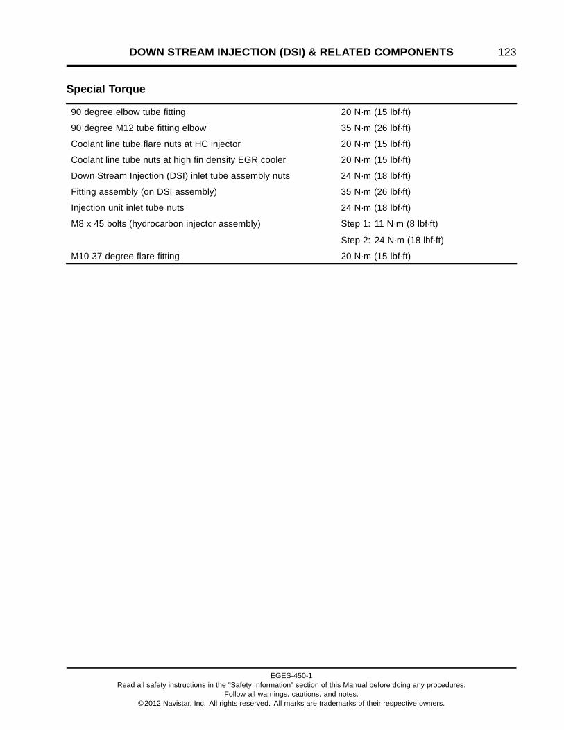
DOWN STREAM INJECTION (DSI) & RELATED COMPONENTS 123
Special Torque
90 degree elbow tube fitting 20 N·m (15 lbf·ft)
90 degree M12 tube fitting elbow 35 N·m (26 lbf·ft)
Coolant line tube flare nuts at HC injector 20 N·m (15 lbf·ft)
Coolant line tube nuts at high fin density EGR cooler 20 N·m (15 lbf·ft)
Down Stream Injection (DSI) inlet tube assembly nuts 24 N·m (18 lbf·ft)
Fitting assembly (on DSI assembly) 35 N·m (26 lbf·ft)
Injection unit inlet tube nuts 24 N·m (18 lbf·ft)
M8 x 45 bolts (hydrocarbon injector assembly) Step 1: 11 N·m (8 lbf·ft)
Step 2: 24 N·m (18 lbf·ft)
M10 37 degree flare fitting 20 N·m (15 lbf·ft)
EGES-450-1Read all safety instructions in the "Safety Information" section of this Manual before doing any procedures.
Follow all warnings, cautions, and notes.©2012 Navistar, Inc. All rights reserved. All marks are trademarks of their respective owners.

124 DOWN STREAM INJECTION (DSI) & RELATED COMPONENTS
EGES-450-1Read all safety instructions in the "Safety Information" section of this Manual before doing any procedures.
Follow all warnings, cautions, and notes.©2012 Navistar, Inc. All rights reserved. All marks are trademarks of their respective owners.

DUAL STAGE TURBOCHARGER AND EXHAUST BRAKE 125
Table of Contents
Exploded View.. . . . . . . . . . . . . . . . . . . . . . . . . . . . . . . . . . . . . . . . . . . . . . . . . . . . . . . . . . . . . . . . . . . . . . . . . . . . . . . . . . . . . . . . . . . . . . . . . . . . . . . . .127
Removal. . . . . . . . . . . . . . . . . . . . . . . . . . . . . . . . . . . . . . . . . . . . . . . . . . . . . . . . . . . . . . . . . . . . . . . . . . . . . . . . . . . . . . . . . . . . . . . . . . . . . . . . . . . . . . . . .130Interstage Inlet Duct Assembly. . . . . . . . . . . . . . . . . . . . . . . . . . . . . . . . . . . . . . . . . . . . . . . . . . . . . . . . . . . . . . . . . . . . . . . . . . . .131Interstage Cooler (ISC). . . . . . . . . . . . . . . . . . . . . . . . . . . . . . . . . . . . . . . . . . . . . . . . . . . . . . . . . . . . . . . . . . . . . . . . . . . . . . . . . . . . . .132Throttle Coupling. . . . . . . . . . . . . . . . . . . . . . . . . . . . . . . . . . . . . . . . . . . . . . . . . . . . . . . . . . . . . . . . . . . . . . . . . . . . . . . . . . . . . . . . . . . . .133Turbocharger Oil Supply Tube Assembly. . . . . . . . . . . . . . . . . . . . . . . . . . . . . . . . . . . . . . . . . . . . . . . . . . . . . . . . . . . . . . . .134Exhaust Brake Valve and Turbocharger Outlet Elbow.. . . . . . . . . . . . . . . . . . . . . . . . . . . . . . . . . . . . . . . . . . . . . . . .135Turbocharger Air Inlet Duct. . . . . . . . . . . . . . . . . . . . . . . . . . . . . . . . . . . . . . . . . . . . . . . . . . . . . . . . . . . . . . . . . . . . . . . . . . . . . . . . .136Turbocharger Wastegate Actuator Assembly. . . . . . . . . . . . . . . . . . . . . . . . . . . . . . . . . . . . . . . . . . . . . . . . . . . . . . . . . . .137Dual Stage Turbocharger Assembly. . . . . . . . . . . . . . . . . . . . . . . . . . . . . . . . . . . . . . . . . . . . . . . . . . . . . . . . . . . . . . . . . . . . . .137
Cleaning, Inspection, and Testing. . . . . . . . . . . . . . . . . . . . . . . . . . . . . . . . . . . . . . . . . . . . . . . . . . . . . . . . . . . . . . . . . . . . . . . . . . . . . . . . . .139Clean Dual Stage Turbocharger Assembly and Related Parts. . . . . . . . . . . . . . . . . . . . . . . . . . . . . . . . . . . . . . .139Inspect Turbine and Compressor. . . . . . . . . . . . . . . . . . . . . . . . . . . . . . . . . . . . . . . . . . . . . . . . . . . . . . . . . . . . . . . . . . . . . . . . . .139Crossover Tube Seal. . . . . . . . . . . . . . . . . . . . . . . . . . . . . . . . . . . . . . . . . . . . . . . . . . . . . . . . . . . . . . . . . . . . . . . . . . . . . . . . . . . . . . . . .139
Installation. . . . . . . . . . . . . . . . . . . . . . . . . . . . . . . . . . . . . . . . . . . . . . . . . . . . . . . . . . . . . . . . . . . . . . . . . . . . . . . . . . . . . . . . . . . . . . . . . . . . . . . . . . . . . .140Dual Stage Turbocharger Assembly. . . . . . . . . . . . . . . . . . . . . . . . . . . . . . . . . . . . . . . . . . . . . . . . . . . . . . . . . . . . . . . . . . . . . .140Turbocharger Wastegate Actuator Assembly (w/o precise regulated shop air pressure). . . . . . .141Turbocharger Wastegate Actuator Assembly (with precise regulated shop air pressure). . . . . .142Turbocharger Air Inlet Duct. . . . . . . . . . . . . . . . . . . . . . . . . . . . . . . . . . . . . . . . . . . . . . . . . . . . . . . . . . . . . . . . . . . . . . . . . . . . . . . . .142Exhaust Brake Valve and Turbocharger Outlet Elbow.. . . . . . . . . . . . . . . . . . . . . . . . . . . . . . . . . . . . . . . . . . . . . . . .143Turbocharger Oil Supply Tube Assembly. . . . . . . . . . . . . . . . . . . . . . . . . . . . . . . . . . . . . . . . . . . . . . . . . . . . . . . . . . . . . . . .145Throttle Coupling. . . . . . . . . . . . . . . . . . . . . . . . . . . . . . . . . . . . . . . . . . . . . . . . . . . . . . . . . . . . . . . . . . . . . . . . . . . . . . . . . . . . . . . . . . . . .146Interstage Cooler (ISC). . . . . . . . . . . . . . . . . . . . . . . . . . . . . . . . . . . . . . . . . . . . . . . . . . . . . . . . . . . . . . . . . . . . . . . . . . . . . . . . . . . . . .146Interstage Inlet Duct Assembly. . . . . . . . . . . . . . . . . . . . . . . . . . . . . . . . . . . . . . . . . . . . . . . . . . . . . . . . . . . . . . . . . . . . . . . . . . . .147
Special Torque.. . . . . . . . . . . . . . . . . . . . . . . . . . . . . . . . . . . . . . . . . . . . . . . . . . . . . . . . . . . . . . . . . . . . . . . . . . . . . . . . . . . . . . . . . . . . . . . . . . . . . . . . .150
Special Service Tools. . . . . . . . . . . . . . . . . . . . . . . . . . . . . . . . . . . . . . . . . . . . . . . . . . . . . . . . . . . . . . . . . . . . . . . . . . . . . . . . . . . . . . . . . . . . . . . . .150
EGES-450-1Read all safety instructions in the "Safety Information" section of this Manual before doing any procedures.
Follow all warnings, cautions, and notes.©2012 Navistar, Inc. All rights reserved. All marks are trademarks of their respective owners.

126 DUAL STAGE TURBOCHARGER AND EXHAUST BRAKE
EGES-450-1Read all safety instructions in the "Safety Information" section of this Manual before doing any procedures.
Follow all warnings, cautions, and notes.©2012 Navistar, Inc. All rights reserved. All marks are trademarks of their respective owners.

DUAL STAGE TURBOCHARGER AND EXHAUST BRAKE 127
Exploded View
Figure 153 Dual stage turbocharger assembly components
1. M8 x 12 high temperature bolt(3)
2. Turbo heat shield3. M8 x 27 high temperature bolt4. M10 special thread nut (5)5. M6 x 16 bolt (2)6. O-ring #305 (2)7. Turbo oil supply tube assembly8. Single cushioned clamp9. M6 x 12 bolt10. Turbocharger air inlet duct
11. Turbo inlet clamp12. Hose clamp13. Breather tube14. Retainer clip15. Turbocharger wastegate
actuator assembly16. M8 x 16 bolt (2)17. M6 nut (2)18. HP turbocharger oil drain tube19. Tube support20. M8 x 25 bolt
21. 24 mm spring clamp22. 26 mm spring clamp23. LP turbocharger oil drain tube24. O-ring, (.734 x .139 in)25. O-ring (green)26. Dual stage turbocharger
assembly27. Turbocharger mounting gasket28. Turbocharger outlet gasket
EGES-450-1Read all safety instructions in the "Safety Information" section of this Manual before doing any procedures.
Follow all warnings, cautions, and notes.©2012 Navistar, Inc. All rights reserved. All marks are trademarks of their respective owners.

128 DUAL STAGE TURBOCHARGER AND EXHAUST BRAKE
Figure 154 Interstage Cooler (ISC) components (245 hp and above)
1. M8 x 110 stud bolt (2)2. Elbow deaeration hose3. M8 x 110 bolt (2)4. 29 mm clipless clamp (2)5. 3.53 x 63.09 ID O-ring6. ISC inlet elbow7. M8 x 30 bolt (2)8. T-bolt (hose) clamp (2)
9. Flexible air hose10. M8 x 25 bolt (5)11. Top ISC duct support12. ISC coolant return tube13. 3/4 in. worm gear clamp (2)14. ISC coolant return hose15. Interstage inlet duct16. Intermediate stage support
17. M10 nut (2)18. Crossover tube seal19. Turbo inlet elbow20. V-band clamp21. 2.62 x 61.6 ID O-ring22. Crossover tube lip seal23. M8 nut24. Interstage Cooler (ISC)
EGES-450-1Read all safety instructions in the "Safety Information" section of this Manual before doing any procedures.
Follow all warnings, cautions, and notes.©2012 Navistar, Inc. All rights reserved. All marks are trademarks of their respective owners.

DUAL STAGE TURBOCHARGER AND EXHAUST BRAKE 129
Figure 155 Exhaust brake valve components
1. Exhaust brake valve supplyhose
2. M10 x 20 bolt (2)3. Exhaust brake valve heat shield4. M10 37 degree flare fitting (2)5. Exhaust brake support assembly6. Exhaust brake valve assembly7. M8 x 20 bolt8. Harness clamp9. M8 nut (2)
10. Exhaust tube fitting11. Exhaust manifold heat shield12. M8 lock nut (3)13. Turbocharger outlet gasket14. Turbocharger outlet elbow15. M10 Special thread nut (3)16. Exhaust brake gasket17. Exhaust clamp18. Cylinder muffler19. Actuator assembly, w/ E clips
20. M12 x 25 bolt21. M12 x 40 bolt (2)22. Turbocharger pipe under rail
support23. Under rail exhaust brake housing24. 1/4 lock nut25. Exhaust brake tube assembly26. 90 degree tube fitting elbow27. Exhaust brake valve to actuator
hose
EGES-450-1Read all safety instructions in the "Safety Information" section of this Manual before doing any procedures.
Follow all warnings, cautions, and notes.©2012 Navistar, Inc. All rights reserved. All marks are trademarks of their respective owners.

130 DUAL STAGE TURBOCHARGER AND EXHAUST BRAKE
Removal
GOVERNMENT REGULATION: Enginefluids (oil, fuel, and coolant) may be a hazardto human health and the environment.Handle all fluids and other contaminatedmaterials (e.g. filters, rags) in accordancewith applicable regulations. Recycleor dispose of engine fluids, filters, andother contaminated materials according toapplicable regulations.
WARNING: Read all safety instructions inthe “Safety Information” section of this manualbefore doing any procedures. Follow all warnings,cautions, and notes.
WARNING: To prevent personal injury ordeath, shift transmission to park or neutral, setparking brake, and block wheels before doingdiagnostic or service procedures.
WARNING: To prevent personal injury ordeath, allow engine to cool before working withcomponents.
WARNING: To prevent personal injury ordeath, disconnect ground (-) cable from batterybefore doing service or diagnostic procedures.
WARNING: To prevent personal injury ordeath, inspect turbocharger with engine off,and turbocharger not spinning. Turbochargercomponents may be extremely hot. Turbochargerwheels are very sharp and spin at high speeds.
WARNING: To prevent personal injury ordeath, wear safety glasses with side shields.Limit compressed air pressure to 207 kPa (30 psi).
WARNING: To prevent personal injury ordeath, use suitable lifting equipment and get helpto remove or install the turbocharger.
WARNING: To prevent personal injury ordeath, do not let engine fluids stay on your skin.Clean skin and nails using hand cleaner and washwith soap and water. Wash or discard clothingand rags contaminated with engine fluids.
EGES-450-1Read all safety instructions in the "Safety Information" section of this Manual before doing any procedures.
Follow all warnings, cautions, and notes.©2012 Navistar, Inc. All rights reserved. All marks are trademarks of their respective owners.

DUAL STAGE TURBOCHARGER AND EXHAUST BRAKE 131
Interstage Inlet Duct Assembly
Figure 156 ISC inlet elbow
1. M8 x 30 bolt (2)2. ISC inlet elbow
1. Remove two M8 x 30 bolts.
2. Remove ISC inlet elbow from ISC.
Figure 157 Interstage inlet duct and top ISCduct support
1. Interstage inlet duct2. M8 x 25 bolt (3)3. Top ISC duct support
3. Remove M8 x 25 bolt from front of top ISC ductsupport.
Figure 158 Intermediate stage support
1. Crossover tube seal2. M8 x 25 bolt (2)3. Intermediate stage support4. M10 nut (2)
4. Remove two M8 x 25 bolts from intermediatestage support.
5. Remove two M10 nuts from EGR cooler studbolts.
6. Remove intermediate stage support.
7. Remove interstage inlet duct assembly.
8. If necessary, remove crossover tube seal by hand.Inspect crossover tube seal for wear or damage.See Crossover Tube Seal (page 139).
EGES-450-1Read all safety instructions in the "Safety Information" section of this Manual before doing any procedures.
Follow all warnings, cautions, and notes.©2012 Navistar, Inc. All rights reserved. All marks are trademarks of their respective owners.

132 DUAL STAGE TURBOCHARGER AND EXHAUST BRAKE
Figure 159 ISC inlet elbow O-ring
1. 3.53 x 63.09 O-ring2. ISC inlet elbow
9. Remove and discard O-ring from ISC inlet elbow.
Interstage Cooler (ISC)
Figure 160 Interstage cooler (ISC)
1. M8 x 110 stud bolt (2)2. Elbow deaeration hose3. Interstage cooler (ISC)4. 29 mm clipless clamp (2)5. M8 x 110 bolt (2)
1. Loosen both 29 mm clipless clamps and removeelbow deaeration hose.
2. Remove two M8 x 110 bolts and two M8 x 110 studbolts.
3. Lift ISC from valve cover and pull off ofturbocharger inlet elbow.
EGES-450-1Read all safety instructions in the "Safety Information" section of this Manual before doing any procedures.
Follow all warnings, cautions, and notes.©2012 Navistar, Inc. All rights reserved. All marks are trademarks of their respective owners.
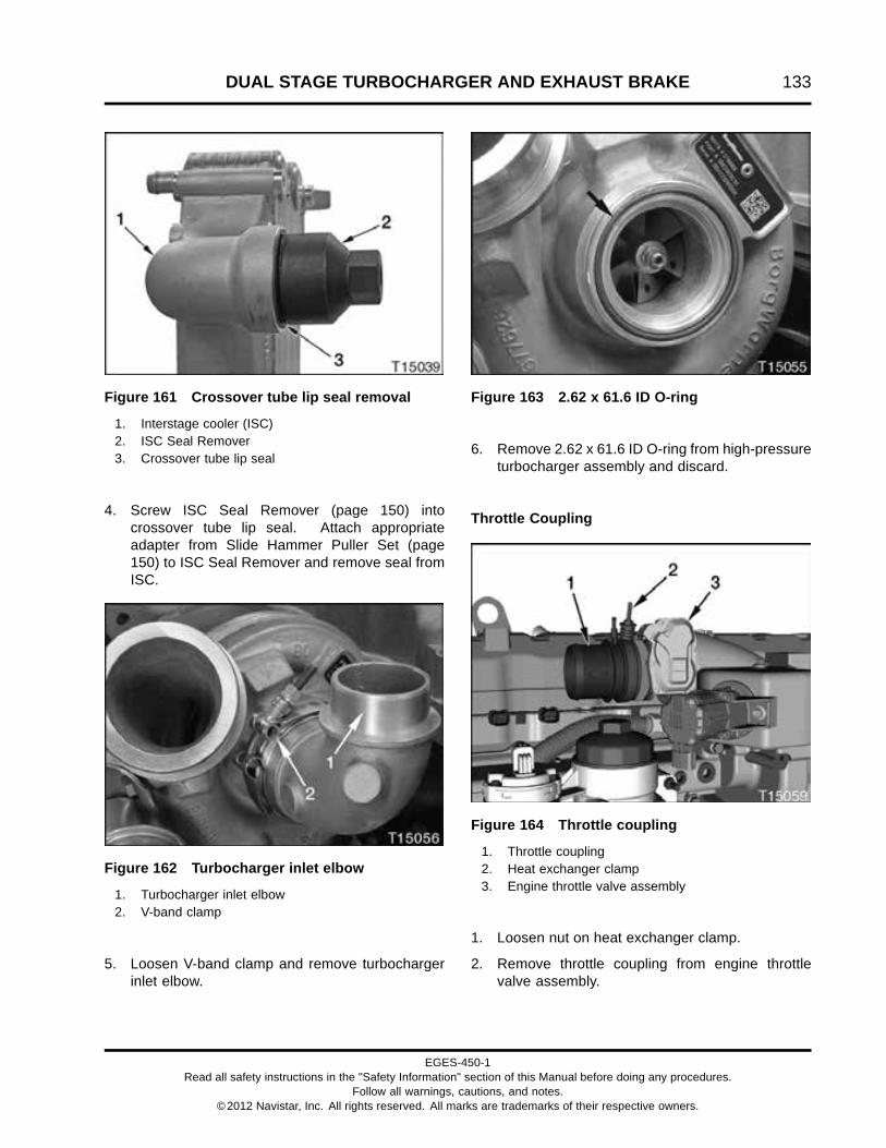
DUAL STAGE TURBOCHARGER AND EXHAUST BRAKE 133
Figure 161 Crossover tube lip seal removal
1. Interstage cooler (ISC)2. ISC Seal Remover3. Crossover tube lip seal
4. Screw ISC Seal Remover (page 150) intocrossover tube lip seal. Attach appropriateadapter from Slide Hammer Puller Set (page150) to ISC Seal Remover and remove seal fromISC.
Figure 162 Turbocharger inlet elbow
1. Turbocharger inlet elbow2. V-band clamp
5. Loosen V-band clamp and remove turbochargerinlet elbow.
Figure 163 2.62 x 61.6 ID O-ring
6. Remove 2.62 x 61.6 ID O-ring from high-pressureturbocharger assembly and discard.
Throttle Coupling
Figure 164 Throttle coupling
1. Throttle coupling2. Heat exchanger clamp3. Engine throttle valve assembly
1. Loosen nut on heat exchanger clamp.
2. Remove throttle coupling from engine throttlevalve assembly.
EGES-450-1Read all safety instructions in the "Safety Information" section of this Manual before doing any procedures.
Follow all warnings, cautions, and notes.©2012 Navistar, Inc. All rights reserved. All marks are trademarks of their respective owners.

134 DUAL STAGE TURBOCHARGER AND EXHAUST BRAKE
Turbocharger Oil Supply Tube Assembly
Figure 165 Turbocharger oil supply tubeassembly
1. Turbocharger oil supply tube nut2. Fitting and O-ring (with screen)3. Oil supply tube assembly4. M6 x 12 bolt
1. Remove turbocharger oil supply tube nut fromfitting and O-ring (with screen) on the oil coolerhousing.
2. Remove M6 x 12 bolt securing turbocharger oilsupply tube assembly retainer to EGR cooler.
Figure 166 Oil supply tube at low-pressureturbocharger assembly
1. M6 x 16 bolt2. Oil supply tube assembly
3. Remove M6 x 16 bolt securing oil supply tubeassembly to low-pressure turbocharger.
Figure 167 Oil supply tube at high-pressureturbocharger assembly
1. M6 x 16 bolt2. Oil supply tube assembly
4. Remove M6 x 16 bolt securing oil supply tubeassembly to high-pressure turbocharger.
5. Remove oil supply tube assembly.
6. Remove and discard two oil supply tube O-rings.
EGES-450-1Read all safety instructions in the "Safety Information" section of this Manual before doing any procedures.
Follow all warnings, cautions, and notes.©2012 Navistar, Inc. All rights reserved. All marks are trademarks of their respective owners.

DUAL STAGE TURBOCHARGER AND EXHAUST BRAKE 135
Exhaust Brake Valve and Turbocharger OutletElbow
Figure 168 Exhaust brake valve and supportbracket
1. 90 degree tube fitting elbow2. Exhaust brake valve to actuator hose3. Under rail exhaust brake housing4. Exhaust clamp5. Turbocharger outlet elbow6. E clip (2)7. Actuator8. M12 x 25 bolt9. Turbocharger pipe under rail support10. M12 x 40 bolt (2)
1. Remove two M12 x 40 bolts from turbochargerpipe under rail support at engine mount and oneM12 x 25 bolt at exhaust brake under rail housing.Remove turbocharger pipe under rail support.
2. Disconnect exhaust brake valve to actuator hosefrom 90 degree tube fitting elbow on actuatorassembly.
3. If required, remove two E clips and removeactuator.
4. Loosen exhaust clamp and remove exhaust brakeunder rail housing from turbocharger outlet elbow.Discard exhaust brake gasket.
Figure 169 Exhaust brake valve assembly
1. Exhaust brake valve to actuator hose2. Exhaust brake valve assembly3. Harness retainer4. M8 nut (2)5. Exhaust brake valve heat shield6. Turbocharger outlet elbow7. Exhaust manifold heat shield8. Exhaust brake tube assembly9. Exhaust brake valve supply hose10. M8 lock nut (3)
5. Disconnect exhaust brake tube assembly fromturbocharger outlet elbow and exhaust brakevalve assembly.
6. Remove three M8 lock nuts and exhaust manifoldheat shield.
7. Disconnect exhaust brake valve to actuatorhose and exhaust brake valve supply hose fromexhaust brake valve assembly.
8. Remove M8 x 20 bolt and harness clamp fromvalve cover (Figure 155) (items 7 and 8).
9. Remove harness retainer from valve cover studbolt.
10. Remove and save two M8 nuts.
11. Remove exhaust brake valve assembly andexhaust brake valve heat shield from exhaustbrake support assembly.
EGES-450-1Read all safety instructions in the "Safety Information" section of this Manual before doing any procedures.
Follow all warnings, cautions, and notes.©2012 Navistar, Inc. All rights reserved. All marks are trademarks of their respective owners.
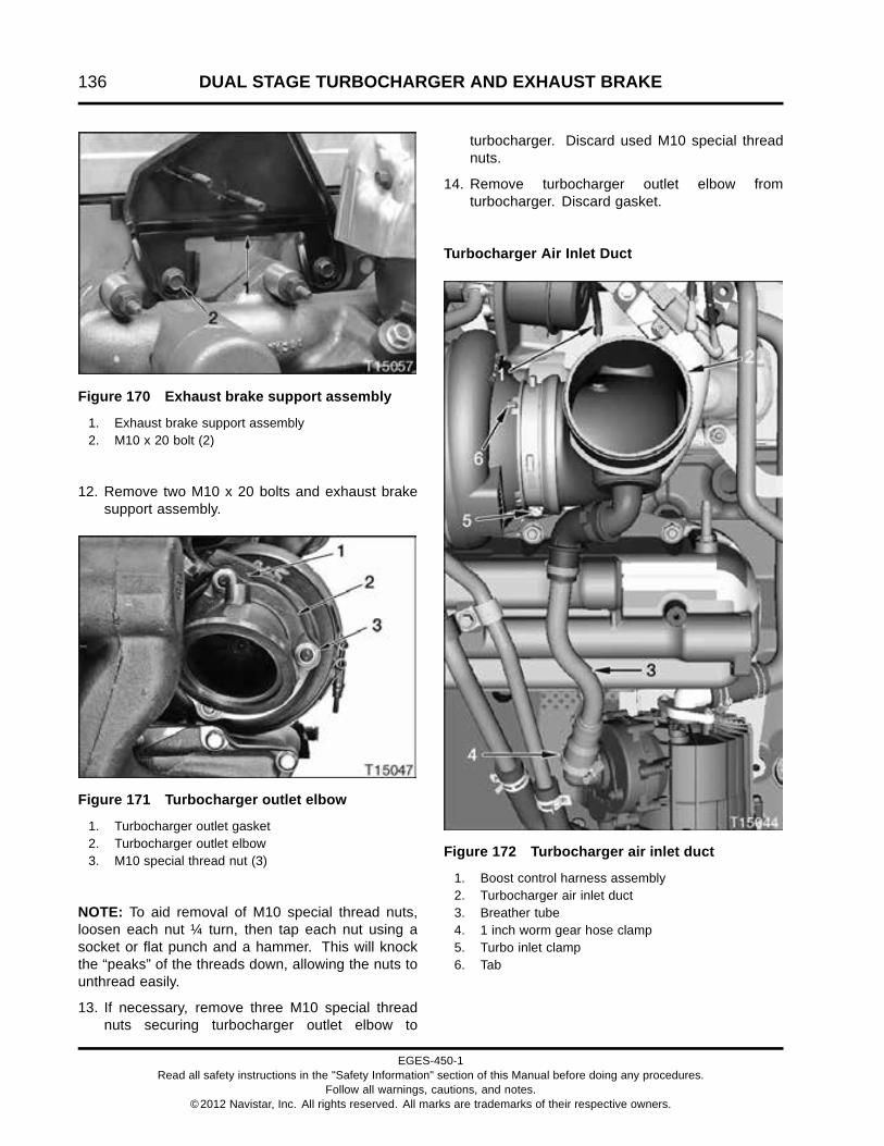
136 DUAL STAGE TURBOCHARGER AND EXHAUST BRAKE
Figure 170 Exhaust brake support assembly
1. Exhaust brake support assembly2. M10 x 20 bolt (2)
12. Remove two M10 x 20 bolts and exhaust brakesupport assembly.
Figure 171 Turbocharger outlet elbow
1. Turbocharger outlet gasket2. Turbocharger outlet elbow3. M10 special thread nut (3)
NOTE: To aid removal of M10 special thread nuts,loosen each nut ¼ turn, then tap each nut using asocket or flat punch and a hammer. This will knockthe “peaks” of the threads down, allowing the nuts tounthread easily.
13. If necessary, remove three M10 special threadnuts securing turbocharger outlet elbow to
turbocharger. Discard used M10 special threadnuts.
14. Remove turbocharger outlet elbow fromturbocharger. Discard gasket.
Turbocharger Air Inlet Duct
Figure 172 Turbocharger air inlet duct
1. Boost control harness assembly2. Turbocharger air inlet duct3. Breather tube4. 1 inch worm gear hose clamp5. Turbo inlet clamp6. Tab
EGES-450-1Read all safety instructions in the "Safety Information" section of this Manual before doing any procedures.
Follow all warnings, cautions, and notes.©2012 Navistar, Inc. All rights reserved. All marks are trademarks of their respective owners.

DUAL STAGE TURBOCHARGER AND EXHAUST BRAKE 137
1. Disconnect boost control harness assembly fromtop of turbocharger air inlet duct.
2. Loosen 1 inch worm gear hose clamp at bottomof breather tube.
3. Loosen turbo inlet clamp and removeturbocharger air inlet duct with breathertube assembly from low–pressure turbocharger.
Turbocharger Wastegate Actuator Assembly
Figure 173 Wastegate actuator
1. Retainer clip2. Wastegate actuator assembly3. M8 x 16 bolt (2)4. Air tube fitting5. Wastegate actuator rod6. M6 nut (inner)7. Pivot block8. M6 nut (outer)9. Wastegate lever
1. Pry retainer clip from actuator rod with ascrewdriver.
2. Remove outer M6 nut from actuator rod.
3. Paint a mark on one of the flats of the inner M6nut to aid in counting turns. Remove the innerM6 nut from the actuator rod while counting theturns used to remove the nut. Make a note of thenumber for use during installation.
4. Disconnect air tube from air tube fitting.
5. Rotate wastegate lever to slide pivot block off ofwastegate actuator rod.
6. Remove two M8 x 16 bolts attaching wastegateactuator assembly to turbocharger assembly.
7. Remove wastegate actuator assembly from dualstage turbocharger assembly.
Dual Stage Turbocharger Assembly
Figure 174 Turbocharger heat shield
1. M8 x 12 high temperature bolt (3)2. Turbocharger heat shield3. M8 x 27 high temperature bolt
1. Remove three M8 x 12 bolts and one M8 x 27 hightemperature bolt from turbocharger heat shield.
2. Remove turbocharger heat shield.
EGES-450-1Read all safety instructions in the "Safety Information" section of this Manual before doing any procedures.
Follow all warnings, cautions, and notes.©2012 Navistar, Inc. All rights reserved. All marks are trademarks of their respective owners.

138 DUAL STAGE TURBOCHARGER AND EXHAUST BRAKE
Figure 175 Dual stage turbocharger assemblyand oil drain tubes
1. M10 special thread nut (5)2. HP turbocharger oil drain tube3. M8 x 25 bolt4. 24 mm spring clamp5. 5/8 hose6. 3/4 hose7. 26 mm spring clamp8. Tube support9. LP turbocharger oil drain tube
3. Remove M8 x 25 bolt from tube support andremove tube support from EGR cooler.
4. Loosen 24 mm spring clamp and disconnect HPoil drain tube from 5/8 hose.
5. Pull HP turbocharger oil drain tube from bottom ofhigh-pressure turbocharger. Remove and discardO-ring (green) from HP turbocharger oil draintube.
6. Loosen 26 mm spring clamp and disconnect LPoil drain tube from 3/4 hose.
7. Pull LP turbocharger oil drain tube from bottom oflow-pressure turbocharger. Remove and discardO-ring from LP turbocharger oil drain tube.
NOTE: To aid removal of turbocharger, loosen fiveM10 special thread nuts ¼ turn then tap each nut usinga socket or flat punch and a hammer. This will knockthe “peaks” of the threads down, allowing the nuts tounthread easily.
WARNING: To prevent personal injury ordeath, support turbocharger assembly duringremoval and installation.
8. Remove five M10 special thread nuts securingthe dual stage turbocharger assembly to exhaustmanifold. Discard used M10 special thread nuts.
9. Remove dual stage turbocharger assembly fromexhaust manifold.
10. Remove and discard turbocharger mountinggasket.
EGES-450-1Read all safety instructions in the "Safety Information" section of this Manual before doing any procedures.
Follow all warnings, cautions, and notes.©2012 Navistar, Inc. All rights reserved. All marks are trademarks of their respective owners.

DUAL STAGE TURBOCHARGER AND EXHAUST BRAKE 139
Cleaning, Inspection, and Testing
WARNING: To prevent personal injury ordeath, wear safety glasses with side shields.Limit compressed air pressure to 207 kPa (30 psi).
Clean Dual Stage Turbocharger Assembly andRelated Parts
1. Clean piping between dual stage turbochargerassembly and air cleaner assembly with soap andwater. Dry piping with filtered compressed air.
2. Clean air inlet piping and connecting hoses anddry with filtered compressed air.
3. Clean turbocharger oil supply tube assembly andoil drain tubes with suitable solvent and a nylonbrush. Dry tubes with filtered compressed air.Replace any damaged tubes.
CAUTION: To prevent turbocharger damage,turbocharger oil supply fitting filter screen mustbe clean.
4. Remove fitting & O-ring (with screen) (Figure165) (item 2) to clean filter screen. Refer toCleaning, Inspection, and Testing (page 255).
5. Clean turbine housing and exhaust manifoldmounting surfaces.
Inspect Turbine and Compressor
NOTE: This inspection can be done with the dualstage turbocharger assembly mounted on or off theengine.
1. Inspect dual stage turbocharger assembly forcracks that may cause air leaks. Replace dualstage turbocharger if necessary.
2. Turn turbine shaft by hand and check for wheelrub in each housing. Shaft wheels must rotatefreely. If there is any rubbing or interference,replace dual stage turbocharger assembly.
NOTE: Do not attempt to straighten bent blades.
3. Inspect compressor impeller and turbine wheels.If any blades are bent, broken, or eroded, replacedual stage turbocharger assembly.
Crossover Tube Seal
1. Inspect crossover tube seal for wear or damageon and around each sealing bead.
2. Inspect for any damage that exposes the steelcore of the seal.
3. The crossover tube seal may be reused if nodamage is found.
EGES-450-1Read all safety instructions in the "Safety Information" section of this Manual before doing any procedures.
Follow all warnings, cautions, and notes.©2012 Navistar, Inc. All rights reserved. All marks are trademarks of their respective owners.

140 DUAL STAGE TURBOCHARGER AND EXHAUST BRAKE
InstallationDual Stage Turbocharger Assembly
Figure 176 Crossover tube seal installation
1. Low-pressure turbocharger2. Crossover tube seal3. Seal Installer4. Seal Installer Handle
1. Apply P-80® Lube (page 150) to outlet oflow-pressure turbocharger and inside ofcrossover tube seal, then install seal onlow-pressure turbocharger using a Seal Installer(page 150).
Figure 177 Turbocharger mounting gasket
1. Exhaust manifold2. Turbocharger mounting gasket
2. Place a new turbocharger mounting gasket onexhaust manifold.
Figure 178 Dual stage turbocharger assemblyand oil drain tubes
1. M10 special thread nut (5)2. HP turbocharger oil drain tube3. M8 x 25 bolt4. 24 mm spring clamp5. 5/8 hose6. 3/4 hose7. 26 mm spring clamp8. Tube support9. LP turbocharger oil drain tube
WARNING: To prevent personal injury ordeath, support turbocharger assembly duringremoval and installation.
NOTE: If removed, install the turbocharger outletelbow on the turbocharger assembly. Installingthe turbocharger outlet elbow is easier while theturbocharger assembly is off the engine. See ExhaustBrake Valve and Turbocharger Outlet Elbow (page143).
3. Lift dual stage turbocharger assembly onto engineand install five new M10 special thread nuts on
EGES-450-1Read all safety instructions in the "Safety Information" section of this Manual before doing any procedures.
Follow all warnings, cautions, and notes.©2012 Navistar, Inc. All rights reserved. All marks are trademarks of their respective owners.

DUAL STAGE TURBOCHARGER AND EXHAUST BRAKE 141
mounting studs. Tighten M10 special thread nutsto special torque (page 150).
4. Pre-lube turbochargers by adding oil to oil supplyport of each turbocharger while rotating turbineshaft. Continue to add oil until oil comes out ofdrain port of each turbocharger.
5. Lubricate oil drain tube O-rings with clean engineoil. Install new 0.734 x 0.139 in. O-ring on LPturbocharger oil drain tube and a new O-ring(green) on the HP turbocharger oil drain tube.
6. Install LP oil drain tube into low-pressureturbocharger. Connect LP oil drain tube to3/4 hose and secure with 26 mm spring clamp.
7. Install HP oil drain tube into high-pressureturbocharger. Connect HP oil drain tube to5/8 hose and secure with 24 mm spring clamp.
8. Install M8 x 25 bolt to secure tube support to EGRcooler. Tighten M8 x 25 bolt to standard torque(page 523).
Figure 179 Turbocharger heat shield
1. M8 x 12 high temperature bolt (3)2. Turbocharger heat shield3. M8 x 27 high temperature bolt
9. Place turbocharger heat shield on HPturbocharger.
10. Install four M8 bolts to secure turbocharger heatshield. Tighten to standard torque (page 523).
Turbocharger Wastegate Actuator Assembly (w/oprecise regulated shop air pressure)
Figure 180 Turbocharger wastegate actuatorassembly
1. Retainer clip2. Wastegate actuator assembly3. M8 x 16 bolt (2)4. Air tube fitting5. Wastegate actuator rod6. M6 nut (inner)7. Pivot block8. M6 nut (outer)9. Wastegate lever
1. Install wastegate actuator assembly on dual stageturbocharger assembly with two M8 x 16 bolts.Tighten bolts to special torque (page 150).
2. Install inner M6 nut onto wastegate actuator rodthe same number of turns noted during removal.(This provides an approximate position for theinner nut).
3. Rotate wastegate lever to slide pivot block ontowastegate actuator rod. Make sure inner M6 nutis at least 10 mm away from pivot block whenwastegate is fully closed (counterclockwise). Turnnut as needed to obtain 10 mm distance frompivot block. (This ensures the inner nut does notinterfere with remaining installation.)
4. Install outer M6 nut on wastegate actuator rod.
5. Hold wastegate lever fully closed(counterclockwise) and hand tighten outer
EGES-450-1Read all safety instructions in the "Safety Information" section of this Manual before doing any procedures.
Follow all warnings, cautions, and notes.©2012 Navistar, Inc. All rights reserved. All marks are trademarks of their respective owners.

142 DUAL STAGE TURBOCHARGER AND EXHAUST BRAKE
M6 nut until it touches pivot block. Mark outer M6nut and tighten additional 3.5 turns.
6. Tighten inner M6 nut to special torque (page 150).
7. Connect air tube to air tube fitting on actuator.
8. Install retainer clip over nuts on wastegateactuator rod.
Turbocharger Wastegate Actuator Assembly(with precise regulated shop air pressure)
NOTE: This method is more precise in establishingwastegate actuator set-point, however, it should onlybe used with properly regulated air pressure.
1. Install wastegate actuator assembly on dual stageturbocharger assembly with two M8 x 16 bolts.Tighten bolts to special torque (page 150).
2. Install inner M6 nut onto wastegate actuator rodthe same number of turns noted during removal.(This provides an approximate position for theinner nut).
3. Rotate wastegate lever to slide pivot block ontowastegate actuator rod. Make sure inner M6 nutis at least 10 mm away from pivot block whenwastegate is fully closed (counterclockwise).(This ensures the inner nut does not interfere withremaining installation.)
4. Install outer M6 nut on wastegate actuator rod.
5. Hold wastegate fully closed (counterclockwise)and hand tighten outer M6 nut until it touchespivot block.
CAUTION: To prevent engine damage, do not applymore then 152 kPa (22 psi) of air pressure to theturbocharger wastegate actuator assembly.
6. Apply air pressure regulated to 55 ± 3.4 kPa (8 ±0.5 psi) to air tube fitting using Pressure Test Kit(page 150). The wastegate actuator rod shouldextend slightly.
7. Hold wastegate lever arm fully closed(counterclockwise) and hand tighten outerM6 nut until it touches pivot block again.
8. Tighten inner M6 nut to special torque (page 150).
9. Remove regulated air pressure and connect airtube to air tube fitting on actuator.
10. Install retainer clip over nuts on wastegateactuator rod.
Turbocharger Air Inlet Duct
Figure 181 Turbocharger air inlet duct
1. Boost control harness assembly (air hose)2. Turbocharger air inlet duct3. Port elbow4. Hose clamp (2)5. Breather tube6. 1 inch worm gear hose clamp7. Turbo inlet clamp8. Tab
1. If removed, slide breather tube hose ontocrankcase breather assembly. Tighten 1 inch
EGES-450-1Read all safety instructions in the "Safety Information" section of this Manual before doing any procedures.
Follow all warnings, cautions, and notes.©2012 Navistar, Inc. All rights reserved. All marks are trademarks of their respective owners.

DUAL STAGE TURBOCHARGER AND EXHAUST BRAKE 143
worm gear hose clamp to standard torque (page523).
2. Install turbo air inlet duct on low-pressureturbocharger. Make sure tab on low-pressureturbocharger aligns with notch on air inlet duct.Tighten clamp to standard torque (page 523).
3. Connect boost control harness assembly (airhose) to fitting on top of turbocharger air inletduct.
Exhaust Brake Valve and Turbocharger OutletElbow
Figure 182 Turbocharger outlet gasket
1. Install a new turbocharger outlet gasket on dualstage turbocharger assembly.
Figure 183 Turbocharger outlet elbow
1. Turbocharger outlet gasket2. Turbocharger outlet elbow3. M10 special thread nut (3)
2. Install turbocharger outlet elbow with three M10special thread nuts. Tighten M10 special threadnuts to special torque (page 150).
Figure 184 Exhaust brake support assembly
1. Exhaust brake support assembly2. M10 x 20 bolt (2)
3. Install exhaust brake support assembly on enginewith two M10 x 20 bolts. Tighten bolts to standardtorque (page 523).
EGES-450-1Read all safety instructions in the "Safety Information" section of this Manual before doing any procedures.
Follow all warnings, cautions, and notes.©2012 Navistar, Inc. All rights reserved. All marks are trademarks of their respective owners.

144 DUAL STAGE TURBOCHARGER AND EXHAUST BRAKE
Figure 185 Exhaust brake valve assembly
1. Exhaust brake valve to actuator hose2. Exhaust brake valve assembly3. Harness retainer4. M8 nut (2)5. Exhaust brake valve heat shield6. Turbocharger outlet elbow7. Exhaust manifold heat shield8. Exhaust brake tube assembly9. Exhaust brake valve supply hose10. M8 lock nut (3)
4. Install exhaust manifold heat shield and three M8lock nuts. Tighten nuts to standard torque (page523).
5. If removed, install M10 37 degree flare fittings(Figure 155) (item 4) and exhaust tube fitting intoexhaust brake valve assembly. Tighten fittings tospecial torque (page 150).
6. Install exhaust brake valve heat shield on exhaustbrake support assembly.
7. Install exhaust brake valve on exhaust brakesupport assembly with two M8 nuts finger tight.Install exhaust brake tube assembly. Tighten M8nuts to standard torque (page 523) and exhaustbrake tube assembly nuts to special torque (page150).
8. Secure wiring to valve cover with harness clampand M8 x 20 bolt (Figure 155) (items 7 and 8).Tighten bolt to standard torque (page 523).
9. Push harness retainer onto valve cover stud.
10. Connect exhaust brake valve supply hose toexhaust brake valve. Tighten exhaust brakevalve supply hose fitting to special torque (page150).
11. Connect exhaust brake valve to actuator hose toexhaust brake valve. Tighten exhaust brake valveto actuator hose fitting to special torque (page150).
Figure 186 Exhaust brake valve and supportbracket
1. 90 degree tube fitting elbow2. Exhaust brake valve to actuator hose3. Exhaust brake under rail housing4. Exhaust clamp5. Turbocharger outlet elbow6. E clip (2)7. Actuator8. M12 x 25 bolt9. Turbocharger pipe under rail support10. M12 x 40 bolt (2)
12. Connect exhaust brake under rail housing toturbocharger outlet elbow using a new exhaustbrake gasket. Do not fully tighten the clamp atthis time. Allow exhaust brake under rail housingto rotate slightly.
13. Install turbocharger pipe under rail support withone M12 x 25 and two M12 x 40 bolts. TightenM12 x 25 bolt to special torque (page 150).Tighten two M12 x 40 bolts to standard torque(page 523).
EGES-450-1Read all safety instructions in the "Safety Information" section of this Manual before doing any procedures.
Follow all warnings, cautions, and notes.©2012 Navistar, Inc. All rights reserved. All marks are trademarks of their respective owners.

DUAL STAGE TURBOCHARGER AND EXHAUST BRAKE 145
14. Tighten exhaust clamp to special torque (page150).
15. Install actuator on exhaust brake under railhousing and secure with E clips.
16. Connect exhaust brake valve to actuator hoseto 90 degree tube fitting elbow. Tighten exhaustbrake valve to actuator hose fitting to specialtorque (page 150).
Turbocharger Oil Supply Tube Assembly
1. Lubricate the turbocharger special seals withclean engine oil. Install new turbocharger specialseals in grooves on oil supply tube assembly.
2. Install turbocharger oil supply tube assembly intodual stage turbocharger assembly.
Figure 187 Oil supply tube assembly atlow-pressure turbocharger assembly
1. M6 x 16 bolt2. Oil supply tube assembly
3. Install M6 x 16 bolt securing oil supply tubeassembly to low-pressure turbocharger. TightenM6 x 16 bolt to standard torque (page 523).
Figure 188 Oil supply tube assembly athigh-pressure turbocharger assembly
1. M6 x 16 bolt2. Oil supply tube assembly
4. Install M6 x 16 bolt securing oil supply tubeassembly to high-pressure turbocharger. TightenM6 x 16 bolt to standard torque (page 523).
Figure 189 Turbocharger oil supply tubeassembly
1. Turbocharger oil supply tube nut2. Fitting and O-ring (with screen)3. Oil supply tube assembly4. M6 x 12 bolt
CAUTION: To prevent turbocharger damage,turbocharger oil supply fitting filter screen mustbe clean.
5. Connect turbocharger oil supply tube assembly tofitting and O-ring (with screen) on the oil cooler
EGES-450-1Read all safety instructions in the "Safety Information" section of this Manual before doing any procedures.
Follow all warnings, cautions, and notes.©2012 Navistar, Inc. All rights reserved. All marks are trademarks of their respective owners.

146 DUAL STAGE TURBOCHARGER AND EXHAUST BRAKE
housing. Tighten turbocharger oil supply tube nutto special torque (page 150).
6. Install M6 x 12 bolt securing turbocharger oilsupply tube assembly retainer to EGR cooler.Tighten bolt to standard torque (page 523).
Throttle Coupling
Figure 190 Throttle coupling
1. Throttle coupling2. Heat exchanger clamp3. Engine throttle valve assembly
1. Install throttle coupling on engine throttle valveassembly.
2. Secure throttle coupling with heat exchangerclamp. Tighten heat exchanger clamp to specialtorque (page 150).
Interstage Cooler (ISC)
Figure 191 2.62 x 61.6 ID O-ring
1. Install a new 2.62 x 61.6 ID O-ring in groove onHP turbocharger.
Figure 192 Turbocharger inlet elbow
1. Turbocharger inlet elbow2. V-band clamp
2. Attach turbocharger inlet elbow to HPturbocharger with V-band clamp. Do notfully tighten V-band clamp at this time. Allowturbocharger inlet elbow to rotate as necessaryto allow for ISC to be installed.
EGES-450-1Read all safety instructions in the "Safety Information" section of this Manual before doing any procedures.
Follow all warnings, cautions, and notes.©2012 Navistar, Inc. All rights reserved. All marks are trademarks of their respective owners.

DUAL STAGE TURBOCHARGER AND EXHAUST BRAKE 147
Figure 193 Crossover tube lip seal
1. Crossover tube lip seal2. ISC
3. Install a new crossover tube lip seal in ISC usingISC Seal Installer (page 150).
Figure 194 Interstage cooler
1. M8 x 110 stud bolt (2)2. Elbow deaeration hose3. ISC4. 29 mm clipless clamp (2)5. M8 x 110 bolt (2)
4. Place ISC on turbocharger inlet elbow and valvecover. Install two M8 x 110 bolts and two M8 x 110stud bolts. Tighten bolts to standard torque (page523).
5. Tighten turbocharger inlet elbow V-band clamp tospecial torque (page 150).
6. Install deaeration hose and secure with two 29mm clipless clamps.
Interstage Inlet Duct Assembly
Figure 195 Crossover tube seal and interstageinlet duct
1. Crossover tube seal2. Interstage inlet duct
1. Apply P-80® Lube (page 150) to outside ofcrossover tube seal and inside of interstage inletduct. Push interstage inlet duct onto crossovertube seal.
EGES-450-1Read all safety instructions in the "Safety Information" section of this Manual before doing any procedures.
Follow all warnings, cautions, and notes.©2012 Navistar, Inc. All rights reserved. All marks are trademarks of their respective owners.

148 DUAL STAGE TURBOCHARGER AND EXHAUST BRAKE
Figure 196 ISC inlet elbow O-ring
1. 3.53 x 63.09 ID O-ring2. ISC inlet elbow
2. Install a new 3.53 x 63.09 ID O-ring into ISC inletelbow.
Figure 197 ISC inlet elbow
1. M8 x 30 bolt (2)2. ISC inlet elbow
3. Install two M8 x 30 bolts to secure ISC inlet elbowto ISC. Tighten bolts to standard torque (page523).
Figure 198 Interstage inlet duct and top frontbracket
1. Interstage inlet duct2. M8 x 25 bolt (3)3. Top ISC duct support
4. Install M8 x 25 bolt through top of ISC duct supportinto interstage inlet duct. Tighten bolt to standardtorque (page 523).
Figure 199 Intermediate stage support
1. Crossover tube seal2. M8 x 25 bolt (2)3. Intermediate stage support4. M10 nut (2)
EGES-450-1Read all safety instructions in the "Safety Information" section of this Manual before doing any procedures.
Follow all warnings, cautions, and notes.©2012 Navistar, Inc. All rights reserved. All marks are trademarks of their respective owners.

DUAL STAGE TURBOCHARGER AND EXHAUST BRAKE 149
5. Place intermediate stage support on EGR coolerstud bolts. Install two M10 nuts finger tight.
6. Install two M8 x 25 bolts finger tight.
7. Tighten M8 x 25 bolts and M10 nuts to standardtorque (page 523).
EGES-450-1Read all safety instructions in the "Safety Information" section of this Manual before doing any procedures.
Follow all warnings, cautions, and notes.©2012 Navistar, Inc. All rights reserved. All marks are trademarks of their respective owners.

150 DUAL STAGE TURBOCHARGER AND EXHAUST BRAKE
Special Torque
Exhaust brake tube assembly nuts 24 N·m (18 lbf·ft)
Exhaust brake valve to actuator hose fitting 20 N·m (15 lbf·ft)
Exhaust brake valve supply hose fitting 20 N·m (15 lbf·ft)
Exhaust clamp 8 N·m (75 lbf·in)
Exhaust tube fitting 24 N·m (18 lbf·ft)
Heat exchanger clamp 7.5 N·m (66 lbf·in)
Turbocharger oil supply tube nut 25 N·m (18 lbf·ft)
Turbocharger mounting nuts, M10 special thread nuts 71 N·m (52 lbf·ft)
Turbocharger outlet elbow, M10 special thread nuts 61 N·m (45 lbf·ft)
Turbocharger pipe under rail support, M12 x 25 bolt 65 N·m (48 lbf·ft)
90 degree tube fitting elbow 35 N·m (26 lbf·ft)
M10 37 degree flare fitting 24 N·m (18 lbf·ft)
Wastegate actuator rod inner M6 nut 8 N·m (75 lbf·in)
M8 x 16 wastegate actuator bolts 15 N·m (11 lbf·ft)
V-band clamp (turbocharger inlet elbow) 17 N·m (12.5 lbf·ft)
Special Service Tools
ISC Seal Installer ZTSE4937–1
ISC Seal Remover ZTSE4937–2
P-80® Lube Obtain locally
Pressure Test Kit ZTSE4409
Seal installer (crossover tube seal) ZTSE6046
Seal installer handle ZTSE6055-1
Slide Hammer Puller Set ZTSE1879
EGES-450-1Read all safety instructions in the "Safety Information" section of this Manual before doing any procedures.
Follow all warnings, cautions, and notes.©2012 Navistar, Inc. All rights reserved. All marks are trademarks of their respective owners.

EXHAUST GAS RECIRCULATION (EGR) SYSTEM 151
Table of Contents
Exploded View.. . . . . . . . . . . . . . . . . . . . . . . . . . . . . . . . . . . . . . . . . . . . . . . . . . . . . . . . . . . . . . . . . . . . . . . . . . . . . . . . . . . . . . . . . . . . . . . . . . . . . . . . .153
Removal. . . . . . . . . . . . . . . . . . . . . . . . . . . . . . . . . . . . . . . . . . . . . . . . . . . . . . . . . . . . . . . . . . . . . . . . . . . . . . . . . . . . . . . . . . . . . . . . . . . . . . . . . . . . . . . . .156Draining High Fin Density EGR Cooler. . . . . . . . . . . . . . . . . . . . . . . . . . . . . . . . . . . . . . . . . . . . . . . . . . . . . . . . . . . . . . . . . . .156High Fin Density EGR Cooler and Components. . . . . . . . . . . . . . . . . . . . . . . . . . . . . . . . . . . . . . . . . . . . . . . . . . . . . . . .157EGR Valve Assembly. . . . . . . . . . . . . . . . . . . . . . . . . . . . . . . . . . . . . . . . . . . . . . . . . . . . . . . . . . . . . . . . . . . . . . . . . . . . . . . . . . . . . . . .160Engine Throttle Valve (ETV) Assembly. . . . . . . . . . . . . . . . . . . . . . . . . . . . . . . . . . . . . . . . . . . . . . . . . . . . . . . . . . . . . . . . . . .160Air and EGR Mixer Duct Assembly. . . . . . . . . . . . . . . . . . . . . . . . . . . . . . . . . . . . . . . . . . . . . . . . . . . . . . . . . . . . . . . . . . . . . . . .160
Cleaning, Inspecting, and Testing. . . . . . . . . . . . . . . . . . . . . . . . . . . . . . . . . . . . . . . . . . . . . . . . . . . . . . . . . . . . . . . . . . . . . . . . . . . . . . . . . .162Cleaning and Inspecting EGR System Components. . . . . . . . . . . . . . . . . . . . . . . . . . . . . . . . . . . . . . . . . . . . . . . . . . .162Air and EGR Mixer Duct Assembly. . . . . . . . . . . . . . . . . . . . . . . . . . . . . . . . . . . . . . . . . . . . . . . . . . . . . . . . . . . . . . . . . . . . . . . .162EGR Valve Assembly. . . . . . . . . . . . . . . . . . . . . . . . . . . . . . . . . . . . . . . . . . . . . . . . . . . . . . . . . . . . . . . . . . . . . . . . . . . . . . . . . . . . . . . .162Engine Throttle Valve Assembly. . . . . . . . . . . . . . . . . . . . . . . . . . . . . . . . . . . . . . . . . . . . . . . . . . . . . . . . . . . . . . . . . . . . . . . . . . .162High Fin Density EGR Cooler. . . . . . . . . . . . . . . . . . . . . . . . . . . . . . . . . . . . . . . . . . . . . . . . . . . . . . . . . . . . . . . . . . . . . . . . . . . . . .162Pressure Testing High Fin Density EGR Cooler. . . . . . . . . . . . . . . . . . . . . . . . . . . . . . . . . . . . . . . . . . . . . . . . . . . . . . . .162
Installation. . . . . . . . . . . . . . . . . . . . . . . . . . . . . . . . . . . . . . . . . . . . . . . . . . . . . . . . . . . . . . . . . . . . . . . . . . . . . . . . . . . . . . . . . . . . . . . . . . . . . . . . . . . . . .165Air and EGR Mixer Duct Assembly. . . . . . . . . . . . . . . . . . . . . . . . . . . . . . . . . . . . . . . . . . . . . . . . . . . . . . . . . . . . . . . . . . . . . . . .165Engine Throttle Valve (ETV) Assembly. . . . . . . . . . . . . . . . . . . . . . . . . . . . . . . . . . . . . . . . . . . . . . . . . . . . . . . . . . . . . . . . . . .166EGR Valve Assembly. . . . . . . . . . . . . . . . . . . . . . . . . . . . . . . . . . . . . . . . . . . . . . . . . . . . . . . . . . . . . . . . . . . . . . . . . . . . . . . . . . . . . . . .166High Fin Density EGR Cooler and Components. . . . . . . . . . . . . . . . . . . . . . . . . . . . . . . . . . . . . . . . . . . . . . . . . . . . . . . .167
Special Torque.. . . . . . . . . . . . . . . . . . . . . . . . . . . . . . . . . . . . . . . . . . . . . . . . . . . . . . . . . . . . . . . . . . . . . . . . . . . . . . . . . . . . . . . . . . . . . . . . . . . . . . . . .169
Special Service Tools. . . . . . . . . . . . . . . . . . . . . . . . . . . . . . . . . . . . . . . . . . . . . . . . . . . . . . . . . . . . . . . . . . . . . . . . . . . . . . . . . . . . . . . . . . . . . . . . .169
EGES-450-1Read all safety instructions in the "Safety Information" section of this Manual before doing any procedures.
Follow all warnings, cautions, and notes.©2012 Navistar, Inc. All rights reserved. All marks are trademarks of their respective owners.

152 EXHAUST GAS RECIRCULATION (EGR) SYSTEM
EGES-450-1Read all safety instructions in the "Safety Information" section of this Manual before doing any procedures.
Follow all warnings, cautions, and notes.©2012 Navistar, Inc. All rights reserved. All marks are trademarks of their respective owners.
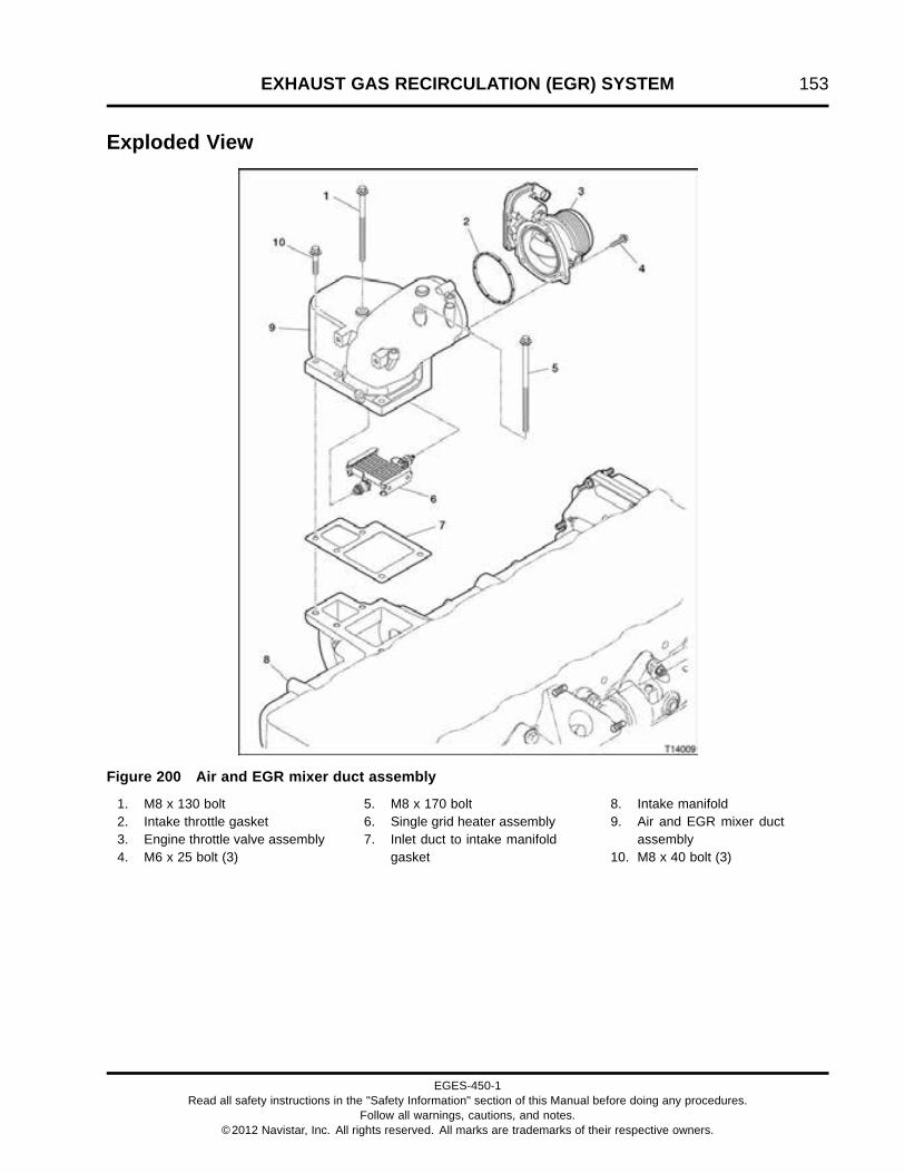
EXHAUST GAS RECIRCULATION (EGR) SYSTEM 153
Exploded View
Figure 200 Air and EGR mixer duct assembly
1. M8 x 130 bolt2. Intake throttle gasket3. Engine throttle valve assembly4. M6 x 25 bolt (3)
5. M8 x 170 bolt6. Single grid heater assembly7. Inlet duct to intake manifold
gasket
8. Intake manifold9. Air and EGR mixer duct
assembly10. M8 x 40 bolt (3)
EGES-450-1Read all safety instructions in the "Safety Information" section of this Manual before doing any procedures.
Follow all warnings, cautions, and notes.©2012 Navistar, Inc. All rights reserved. All marks are trademarks of their respective owners.
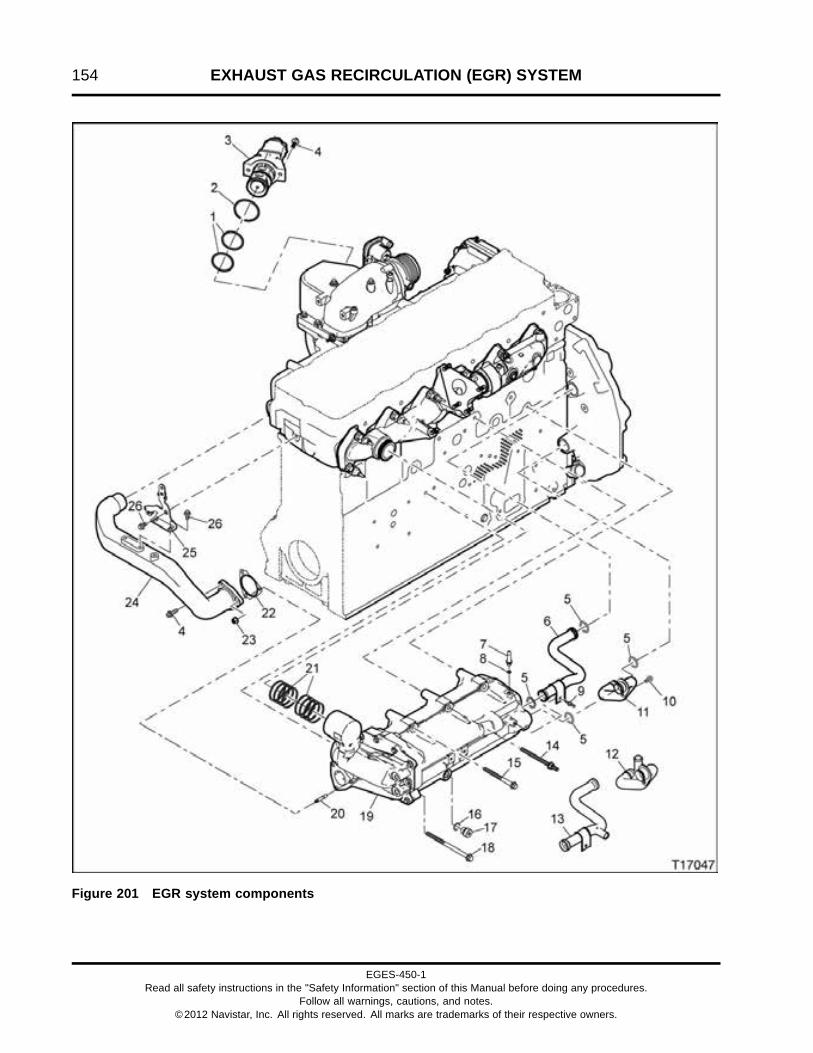
154 EXHAUST GAS RECIRCULATION (EGR) SYSTEM
Figure 201 EGR system components
EGES-450-1Read all safety instructions in the "Safety Information" section of this Manual before doing any procedures.
Follow all warnings, cautions, and notes.©2012 Navistar, Inc. All rights reserved. All marks are trademarks of their respective owners.

EXHAUST GAS RECIRCULATION (EGR) SYSTEM 155
1. 3.5 x 46.8 ID O-ring (2)2. EGR valve seal3. EGR valve assembly4. M8 x 10 prevailing torque bolt (3)5. O-ring seal (4)6. Coolant supply tube assembly
(w/o interstage cooler)7. Deaeration fitting8. O-ring seal9. M6 x 16 stud bolt10. M6 x 12 bolt
11. Coolant return tube assembly(w/o interstage cooler)
12. Coolant return tube assembly(with interstage cooler)
13. Coolant supply tube assembly(with interstage cooler)
14. M10 x 110 stud bolt (2)15. M10 x 110 bolt16. Seal17. M18 O-ring boss plug18. M10 x 160 bolt (2)
19. High fin density EGR cooler20. M8 x 1.25 stud with LKG thread
(2)21. Exhaust ring seal (8)22. Exhaust gasket23. M8 nut (2)24. EGR crossover duct25. Crossover tube support26. M8 x 16 bolt (with interstage
cooler) (3)
EGES-450-1Read all safety instructions in the "Safety Information" section of this Manual before doing any procedures.
Follow all warnings, cautions, and notes.©2012 Navistar, Inc. All rights reserved. All marks are trademarks of their respective owners.

156 EXHAUST GAS RECIRCULATION (EGR) SYSTEM
Removal
GOVERNMENT REGULATION: Enginefluids (oil, fuel, and coolant) may be a hazardto human health and the environment.Handle all fluids and other contaminatedmaterials (e.g. filters, rags) in accordancewith applicable regulations. Recycleor dispose of engine fluids, filters, andother contaminated materials according toapplicable regulations.
WARNING: To prevent personal injury ordeath, read all safety instructions in the “SafetyInformation” section of this manual.
WARNING: To prevent personal injury ordeath, shift transmission to park or neutral, setparking brake, and block wheels before doingdiagnostic or service procedures.
WARNING: To prevent personal injury ordeath, do not let engine fluids stay on your skin.Clean skin and nails using hand cleaner and washwith soap and water. Wash or discard clothingand rags contaminated with engine fluids.
WARNING: To prevent personal injury ordeath, wear safety glasses with side shields.
Draining High Fin Density EGR Cooler
WARNING: To prevent personal injury ordeath, allow engine to cool before drainingcoolant.
Figure 202 M18 O-ring boss plug (drain plug)
1. Place a coolant drain pan under M18 O-ring bossplug.
2. Remove M18 O-ring boss plug to allow coolant todrain from EGR cooler.
3. Remove and discard O-ring from M18 O-ring bossplug.
4. Install a new O-ring on M18 O-ring boss plug.
5. After coolant has drained, install M18 O-ring bossplug into high fin density EGR cooler.
6. Tighten M18 O-ring boss plug to standard torque(page 523).
7. Recycle or dispose of coolant according toapplicable regulations.
EGES-450-1Read all safety instructions in the "Safety Information" section of this Manual before doing any procedures.
Follow all warnings, cautions, and notes.©2012 Navistar, Inc. All rights reserved. All marks are trademarks of their respective owners.

EXHAUST GAS RECIRCULATION (EGR) SYSTEM 157
High Fin Density EGR Cooler and Components
1. Remove injection unit inlet tube assembly,hydrocarbon injector assembly and injectorcoolant inlet and outlet tubes. See Injection UnitInlet Tube Assembly (page 117) and HydrocarbonInjector Assembly (page 117).
2. Remove exhaust brake valve assembly andturbocharger oil supply tube. See ExhaustBrake Valve and Turbocharger Outlet Elbow(page 135) and Turbocharger Oil Supply TubeAssembly (page 134).
Figure 203 High fin density EGR cooler tocrossover duct connection
1. EGR crossover duct2. M8 x 10 prevailing torque bolt3. High fin density EGR cooler4. M8 nut (2)
3. Remove two M8 nuts and one M8 x 10 prevailingtorque bolt connecting EGR crossover duct tohigh fin density EGR cooler.
Figure 204 EGR crossover duct and crossovertube support
1. Intake manifold2. M8 x 16 bolt (3)3. Crossover tube support4. Exhaust manifold5. EGR crossover duct
4. Loosen and remove M8 x 16 bolt securingcrossover tube support to rear of cylinder head.
5. Pull back and disconnect EGR crossover duct(with crossover tube support still attached) fromhigh fin density EGR cooler and intake manifold.
6. Remove and discard seal from intake manifold.See Intake Manifold, Fuel Valve, and Fuel RailPlugs (page 176).
EGES-450-1Read all safety instructions in the "Safety Information" section of this Manual before doing any procedures.
Follow all warnings, cautions, and notes.©2012 Navistar, Inc. All rights reserved. All marks are trademarks of their respective owners.

158 EXHAUST GAS RECIRCULATION (EGR) SYSTEM
Figure 205 High fin density EGR cooler exhaustgasket
1. Exhaust gasket2. High fin density EGR cooler3. M8 stud (2)
7. Remove exhaust gasket from high fin densityEGR cooler. Discard gasket.
8. Remove alternator support. See AlternatorSupport (page 285).
EGES-450-1Read all safety instructions in the "Safety Information" section of this Manual before doing any procedures.
Follow all warnings, cautions, and notes.©2012 Navistar, Inc. All rights reserved. All marks are trademarks of their respective owners.

EXHAUST GAS RECIRCULATION (EGR) SYSTEM 159
Figure 206 High fin density EGR cooler
1. M10 x 110 bolt2. M10 x 110 stud bolt (2)3. EGR coolant supply tube
4. EGR coolant return tube5. 3/4 inch worm gear clamp6. M6 x 12 bolt
7. M6 x 16 bolt8. M10 x 160 bolt (2)
9. Remove M6 x 16 bolt securing EGR coolantsupply tube to EGR cooler. Push EGR coolantsupply tube forward (deeper into rear half of frontcover) to expose free end of tube at EGR cooler.Swing free end of tube up to clear EGR cooler.Pull tube rearward out of rear half of front cover.Remove and discard tube seals.
NOTE: Do next step if equipped with interstage cooler;if not, go to step 12.
10. If engine is equipped with an interstage cooler,loosen 3/4 inch worm gear hose clamp andremove hose from EGR coolant return tube.
11. Remove M6 x 12 bolt securing EGR coolant returntube to EGR cooler. Push EGR coolant returntube forward (deeper into rear half of front cover)
to expose free end of tube at EGR cooler. Swingfree end of tube downward to clear EGR cooler.Pull tube rearward out of rear half of front cover.Remove and discard tube seals.
12. Remove two M10 x 160 bolts.
13. Remove two M10 x 110 stud bolts. Install bothEGR Cooler Guide Pins (page 169) into the emptybolt holes.
14. Remove M10 x 110 bolt.
15. Remove high fin density EGR cooler fromcrankcase and exhaust manifold by pullingstraight out from exhaust manifold.
16. Remove eight exhaust seal rings from grooves onexhaust manifold and discard.
EGES-450-1Read all safety instructions in the "Safety Information" section of this Manual before doing any procedures.
Follow all warnings, cautions, and notes.©2012 Navistar, Inc. All rights reserved. All marks are trademarks of their respective owners.
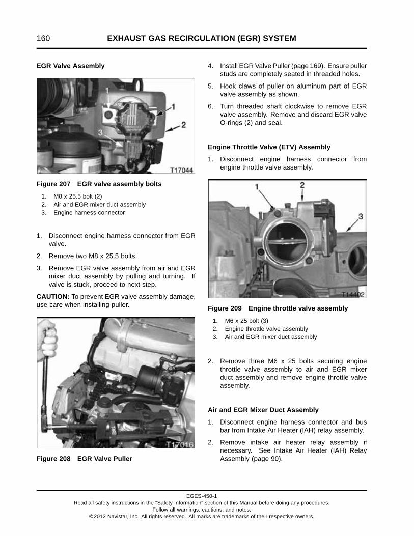
160 EXHAUST GAS RECIRCULATION (EGR) SYSTEM
EGR Valve Assembly
Figure 207 EGR valve assembly bolts
1. M8 x 25.5 bolt (2)2. Air and EGR mixer duct assembly3. Engine harness connector
1. Disconnect engine harness connector from EGRvalve.
2. Remove two M8 x 25.5 bolts.
3. Remove EGR valve assembly from air and EGRmixer duct assembly by pulling and turning. Ifvalve is stuck, proceed to next step.
CAUTION: To prevent EGR valve assembly damage,use care when installing puller.
Figure 208 EGR Valve Puller
4. Install EGR Valve Puller (page 169). Ensure pullerstuds are completely seated in threaded holes.
5. Hook claws of puller on aluminum part of EGRvalve assembly as shown.
6. Turn threaded shaft clockwise to remove EGRvalve assembly. Remove and discard EGR valveO-rings (2) and seal.
Engine Throttle Valve (ETV) Assembly
1. Disconnect engine harness connector fromengine throttle valve assembly.
Figure 209 Engine throttle valve assembly
1. M6 x 25 bolt (3)2. Engine throttle valve assembly3. Air and EGR mixer duct assembly
2. Remove three M6 x 25 bolts securing enginethrottle valve assembly to air and EGR mixerduct assembly and remove engine throttle valveassembly.
Air and EGR Mixer Duct Assembly
1. Disconnect engine harness connector and busbar from Intake Air Heater (IAH) relay assembly.
2. Remove intake air heater relay assembly ifnecessary. See Intake Air Heater (IAH) RelayAssembly (page 90).
EGES-450-1Read all safety instructions in the "Safety Information" section of this Manual before doing any procedures.
Follow all warnings, cautions, and notes.©2012 Navistar, Inc. All rights reserved. All marks are trademarks of their respective owners.

EXHAUST GAS RECIRCULATION (EGR) SYSTEM 161
Figure 210 Air and EGR mixer duct assembly(top view)
1. Intake manifold2. M8 x 40 bolt (3)3. M8 x 130 bolt4. M8 x 170 bolt
3. Remove M8 x 170 bolt.
4. Remove M8 x 130 bolt.
5. Remove three M8 x 40 bolts securing air and EGRmixer duct assembly to intake manifold.
6. Remove air and EGR mixer duct assembly anddiscard inlet duct to intake manifold gasket.
EGES-450-1Read all safety instructions in the "Safety Information" section of this Manual before doing any procedures.
Follow all warnings, cautions, and notes.©2012 Navistar, Inc. All rights reserved. All marks are trademarks of their respective owners.

162 EXHAUST GAS RECIRCULATION (EGR) SYSTEM
Cleaning, Inspecting, and Testing
WARNING: To prevent personal injury ordeath, wear safety glasses with side shields.Limit compressed air pressure to 207 kPa (30 psi).
Cleaning and Inspecting EGR SystemComponents
NOTE: To maintain and ensure peak engineperformance, it is critical to do the following cleaningand inspecting procedures.
1. Clean all mating surfaces to ensure proper gasketsealing.
2. Inspect all EGR system components (Figure201) for cracks, leaks, and damage. Replacedamaged parts as required.
Air and EGR Mixer Duct Assembly
1. Inspect air and EGR mixer duct assembly andintake throttle assembly for cracks or damage.Replace if necessary.
2. Inspect electrical connections of inlet air heaterelement and engine harness connectors forcorrosion or damage. Replace air and EGRmixer duct assembly if necessary.
EGR Valve Assembly
1. Inspect EGR valve to make sure it is fully closed.Replace the valve if necessary.
2. Inspect electrical connections on EGR valveassembly and engine harness connector forcorrosion or damage. Replace if necessary.
NOTE: Refer to MaxxForce® DT, 9, and 10 EngineDiagnostic Manual for functional check of EGR valveassembly.
Engine Throttle Valve Assembly
1. Inspect engine throttle valve assembly sealingsurfaces and body for cracks or damage. Replaceengine throttle valve if sealing surfaces arecracked or damaged.
2. Inspect the butterfly screws. Replace enginethrottle valve if screws are loose or missing.
3. Inspect electrical connections on engine throttlevalve assembly and engine harness connector forcorrosion or damage. Replace if necessary.
High Fin Density EGR Cooler
NOTE: The high fin density EGR cooler shouldbe leak tested both before and after cleaning. Ifrepeated clogging occurs in the EGR cooler on thesame engine, replace the EGR cooler, verify there areno trouble codes and inspect ECM for latest softwareversion to ensure engine is running properly.
1. Clean all mating surfaces to ensure proper gasketsealing.
2. Loose carbon can be removed by flowing waterthrough the EGR cooler in both directions or bysubmerging the EGR cooler in water a few timesand allowing it to drain out.
Pressure Testing High Fin Density EGR Cooler
NOTE: Clean all sealing surfaces on EGR cooler toensure proper sealing of all leak test tools and toeliminate misdiagnosis.
Figure 211 High fin density EGR cooler pressuretest setup – front
1. Knurled knob2. EGR cooler vent tool3. EGR cooler coolant port tool4. Knurled knobs5. Knurled screw
EGES-450-1Read all safety instructions in the "Safety Information" section of this Manual before doing any procedures.
Follow all warnings, cautions, and notes.©2012 Navistar, Inc. All rights reserved. All marks are trademarks of their respective owners.
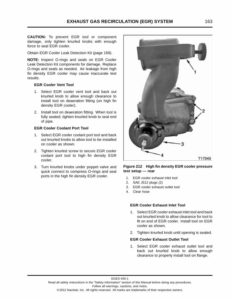
EXHAUST GAS RECIRCULATION (EGR) SYSTEM 163
CAUTION: To prevent EGR tool or componentdamage, only tighten knurled knobs with enoughforce to seal EGR cooler.
Obtain EGR Cooler Leak Detection Kit (page 169).
NOTE: Inspect O-rings and seals on EGR CoolerLeak Detection Kit components for damage. ReplaceO-rings and seals as needed. Air leakage from highfin density EGR cooler may cause inaccurate testresults.
EGR Cooler Vent Tool
1. Select EGR cooler vent tool and back outknurled knob to allow enough clearance toinstall tool on deaeration fitting (on high findensity EGR cooler).
2. Install tool on deaeration fitting. When tool isfully seated, tighten knurled knob to seal endof pipe.
EGR Cooler Coolant Port Tool
1. Select EGR cooler coolant port tool and backout knurled knobs to allow tool to be installedon cooler as shown.
2. Tighten knurled screw to secure EGR coolercoolant port tool to high fin density EGRcooler.
3. Turn knurled knobs under poppet valve andquick connect to compress O-rings and sealports in the high fin density EGR cooler.
Figure 212 High fin density EGR cooler pressuretest setup — rear
1. EGR cooler exhaust inlet tool2. SAE J512 plugs (2)3. EGR cooler exhaust outlet tool4. Clear hose
EGR Cooler Exhaust Inlet Tool
1. Select EGR cooler exhaust inlet tool and backout knurled knob to allow clearance for tool tofit on end of EGR cooler. Install tool on EGRcooler as shown.
2. Tighten knurled knob until opening is sealed.
EGR Cooler Exhaust Outlet Tool
1. Select EGR cooler exhaust outlet tool andback out knurled knob to allow enoughclearance to properly install tool on flange.
EGES-450-1Read all safety instructions in the "Safety Information" section of this Manual before doing any procedures.
Follow all warnings, cautions, and notes.©2012 Navistar, Inc. All rights reserved. All marks are trademarks of their respective owners.

164 EXHAUST GAS RECIRCULATION (EGR) SYSTEM
2. Place tool over flange so flange fits in toolopening. The cutout portion of tool providesclearance around EGR cooler. Turn toolclockwise until flange contacts stops on tool.
3. Tighten knurled knob on EGR cooler exhaustoutlet tool until rubber seal contacts flange.
SAE J512 Plugs
1. Seal the two hydrocarbon injector coolant lineports with SAE J512 plugs (page 169).
2. Tighten SAE J512 plugs only enough to sealports.
NOTE: The poppet valve is set to open at 80 psi forsafety and to prevent damage to the EGR cooler.
EGR Cooler Leak Test
1. Connect an air hose, regulated to 50 psi, toquick connect on EGR cooler coolant porttool.
2. Place red end of clear hose from EGR coolerexhaust outlet tool into a container of waterand watch for air bubbles. Submerge only thered portion of the hose in water. Air bubblesindicate a leak in the EGR cooler. It is notnecessary to pressurize the EGR cooler formore than 5 minutes. Replace EGR cooler ifair comes out of clear hose.
3. Disconnect air hose from EGR cooler coolantport tool.
4. Remove tools and SAE J512 plugs from EGRcooler. Clean tools as needed and place themin their storage case for future use.
EGES-450-1Read all safety instructions in the "Safety Information" section of this Manual before doing any procedures.
Follow all warnings, cautions, and notes.©2012 Navistar, Inc. All rights reserved. All marks are trademarks of their respective owners.

EXHAUST GAS RECIRCULATION (EGR) SYSTEM 165
InstallationCAUTION: To prevent engine damage, do not usepower tools to install EGR system nuts and bolts.EGR system nuts and bolts will be damaged if rotatedtoo quickly.
NOTE: Apply a light coat of clean engine oil on boltthreads and under bolt head when installing used nutsand bolts.
Air and EGR Mixer Duct Assembly
Figure 213 Mixing Bowl Gasket Alignment Pins
1. Intake manifold2. Inlet duct to intake manifold gasket3. Mixing bowl gasket alignment pin (2)
1. Install two Mixing Bowl Gasket Alignment Pins(page 169) to intake manifold.
2. Install a new inlet duct to intake manifold gasketon intake manifold and install air and EGR mixerduct assembly on intake manifold.
Figure 214 Air and EGR mixer duct assembly
1. Intake manifold2. M8 x 40 bolt (3)3. M8 x 130 bolt4. M8 x 170 bolt
3. Install M8 x 170 bolt finger tight.
4. Install M8 x 130 bolt finger tight.
5. Remove two Mixing Bowl Gasket Alignment Pins(page 169).
6. Install three M8 x 40 bolts finger tight.
7. Tighten three M8 x 40 bolts, M8 x 130 bolt, andM8 x 170 bolt to standard torque (page 523).
EGES-450-1Read all safety instructions in the "Safety Information" section of this Manual before doing any procedures.
Follow all warnings, cautions, and notes.©2012 Navistar, Inc. All rights reserved. All marks are trademarks of their respective owners.

166 EXHAUST GAS RECIRCULATION (EGR) SYSTEM
Engine Throttle Valve (ETV) Assembly
Figure 215 ETV assembly
1. M6 x 25 bolt (3)2. Engine throttle valve assembly3. Air and EGR mixer duct assembly
1. Install engine throttle valve assembly on air andEGR mixer duct assembly with new inlet throttlegasket and finger tighten three M6 x 25 bolts.
2. Tighten three M6 x 25 bolts to special torque(page 169).
EGR Valve Assembly
Figure 216 EGR valve assembly
1. EGR valve seal2. O-ring (2)
1. Install new EGR valve seal and O-rings. Do notapply engine oil to O-rings or seal.
2. Install EGR valve assembly into air and EGRmixer duct assembly. Push and turn as neededuntil valve is completely seated and bolt holesline up.
Figure 217 EGR valve assembly bolts
1. M8 x 25.5 bolt (2)2. Air and EGR mixer duct assembly3. EGR harness connector
3. Install two M8 x 25.5 bolts and tighten to standardtorque (page 523).
EGES-450-1Read all safety instructions in the "Safety Information" section of this Manual before doing any procedures.
Follow all warnings, cautions, and notes.©2012 Navistar, Inc. All rights reserved. All marks are trademarks of their respective owners.

EXHAUST GAS RECIRCULATION (EGR) SYSTEM 167
High Fin Density EGR Cooler and Components
Figure 218 High fin density EGR cooler
1. M10 x 110 bolt2. M10 x 110 stud bolt (2)3. EGR coolant supply tube
4. EGR coolant return tube5. 3/4 inch worm gear clamp (with
ISC)
6. M6 x 12 bolt7. M6 x 16 bolt8. M10 x 160 bolt (2)
1. Install eight new exhaust sealing rings on exhaustmanifold. See Exhaust Manifold (page 179).
2. Install EGR Cooler Guide Pins (page 169) into twoupper bolt holes.
3. Place EGR cooler onto EGR Cooler Guide Pins(page 169) and slide toward crankcase andexhaust manifold.
4. Install two M10 x 160 bolts, remove EGR CoolerGuide Pins (page 169) and then install one M10 x110 bolt, and two M10 x 110 stud bolts to EGRcooler to crankcase. Tighten bolts to standardtorque (page 523).
5. Install new O-ring seals (one on each end) oncoolant return tube. Lightly lubricate seals withengine coolant. Insert coolant return tube into rearhalf of front cover first until opposite end can clearEGR cooler. Insert opposite end of coolant returntube into port of EGR cooler.
6. Connect coolant hose to coolant return tube andsecure with 3/4 inch worm gear clamp. Tightenclamp to standard torque (page 523).
7. Install M6 x 12 bolt to secure EGR coolant returntube to high fin density EGR cooler. Tighten boltto standard torque (page 523).
8. Install new O-ring seals (one on each end) oncoolant supply tube. Lightly lubricate seals withengine coolant. Insert coolant supply tube intorear half of front cover until opposite end can clearEGR cooler. Insert opposite end of coolant supplytube into port of EGR cooler.
9. Install M6 x 16 bolt to secure EGR coolant supplytube to EGR cooler. Tighten bolt to standardtorque (page 523).
10. Using EGR Tube Seal Installer (page 169), installnew EGR pipe seal into the intake manifold. SeeIntake Manifold, Fuel Valve, and Fuel Rail Plugs(page 181).
EGES-450-1Read all safety instructions in the "Safety Information" section of this Manual before doing any procedures.
Follow all warnings, cautions, and notes.©2012 Navistar, Inc. All rights reserved. All marks are trademarks of their respective owners.

168 EXHAUST GAS RECIRCULATION (EGR) SYSTEM
Figure 219 High fin density EGR cooler exhaustgasket
1. Exhaust gasket2. High fin density EGR cooler3. M8 stud (2)
11. Install a new exhaust gasket on high fin densityEGR cooler.
Figure 220 High fin density EGR cooler tocrossover duct connection
1. EGR crossover duct2. M8 x 10 prevailing torque bolt3. High fin density EGR cooler4. M8 nut (2)
12. Push EGR crossover duct over high fin densityEGR cooler studs and straight into intakemanifold.
13. Install two M8 nuts and one M8 x 10 prevailingtorque bolt to secure high fin density EGR coolerto EGR crossover duct. Tighten to standardtorque (page 523).
Figure 221 EGR crossover duct and crossovertube support
1. Intake manifold2. M8 x 16 bolt (3)3. Crossover tube support4. Exhaust manifold5. EGR crossover duct
14. Loosen two M8 x 16 bolts holding crossover tubesupport to EGR crossover duct. The crossovertube support must be able to move freely on EGRcrossover duct.
15. Install M8 x 16 bolt to secure crossover tubesupport to rear of cylinder head. Tighten bolt tocylinder head first, then the other two bolts tostandard torque (page 523).
EGES-450-1Read all safety instructions in the "Safety Information" section of this Manual before doing any procedures.
Follow all warnings, cautions, and notes.©2012 Navistar, Inc. All rights reserved. All marks are trademarks of their respective owners.

EXHAUST GAS RECIRCULATION (EGR) SYSTEM 169
Special Torque
Engine throttle valve M6 x 25 bolts 13 N·m (120 lbf·in)
Special Service Tools
EGR Cooler Guide Pins ZTSE4945
EGR Cooler Leak Detection Kit KL 20030 NAV
EGR Valve Puller ZTSE4941
EGR Tube Seal Installer ZTSE4997
SAE J512 plugs Obtain locally
Mixing Bowl Gasket Alignment Pins ZTSE4955
EGES-450-1Read all safety instructions in the "Safety Information" section of this Manual before doing any procedures.
Follow all warnings, cautions, and notes.©2012 Navistar, Inc. All rights reserved. All marks are trademarks of their respective owners.

170 EXHAUST GAS RECIRCULATION (EGR) SYSTEM
EGES-450-1Read all safety instructions in the "Safety Information" section of this Manual before doing any procedures.
Follow all warnings, cautions, and notes.©2012 Navistar, Inc. All rights reserved. All marks are trademarks of their respective owners.

INTAKE, INLET, AND EXHAUST MANIFOLDS 171
Table of Contents
Exploded View.. . . . . . . . . . . . . . . . . . . . . . . . . . . . . . . . . . . . . . . . . . . . . . . . . . . . . . . . . . . . . . . . . . . . . . . . . . . . . . . . . . . . . . . . . . . . . . . . . . . . . . . . .173
Removal. . . . . . . . . . . . . . . . . . . . . . . . . . . . . . . . . . . . . . . . . . . . . . . . . . . . . . . . . . . . . . . . . . . . . . . . . . . . . . . . . . . . . . . . . . . . . . . . . . . . . . . . . . . . . . . . .174Exhaust Manifold. . . . . . . . . . . . . . . . . . . . . . . . . . . . . . . . . . . . . . . . . . . . . . . . . . . . . . . . . . . . . . . . . . . . . . . . . . . . . . . . . . . . . . . . . . . . .175Intake Manifold, Fuel Valve, and Fuel Rail Plugs.. . . . . . . . . . . . . . . . . . . . . . . . . . . . . . . . . . . . . . . . . . . . . . . . . . . . . .176
Cleaning, Inspection, and Measurements. . . . . . . . . . . . . . . . . . . . . . . . . . . . . . . . . . . . . . . . . . . . . . . . . . . . . . . . . . . . . . . . . . . . . . . . .178Exhaust Manifold. . . . . . . . . . . . . . . . . . . . . . . . . . . . . . . . . . . . . . . . . . . . . . . . . . . . . . . . . . . . . . . . . . . . . . . . . . . . . . . . . . . . . . . . . . . . .178Exhaust Back Pressure (EBP) Sensor Tube Assembly. . . . . . . . . . . . . . . . . . . . . . . . . . . . . . . . . . . . . . . . . . . . . . . .178Intake Manifold. . . . . . . . . . . . . . . . . . . . . . . . . . . . . . . . . . . . . . . . . . . . . . . . . . . . . . . . . . . . . . . . . . . . . . . . . . . . . . . . . . . . . . . . . . . . . . . .178
Installation. . . . . . . . . . . . . . . . . . . . . . . . . . . . . . . . . . . . . . . . . . . . . . . . . . . . . . . . . . . . . . . . . . . . . . . . . . . . . . . . . . . . . . . . . . . . . . . . . . . . . . . . . . . . . .179Exhaust Manifold. . . . . . . . . . . . . . . . . . . . . . . . . . . . . . . . . . . . . . . . . . . . . . . . . . . . . . . . . . . . . . . . . . . . . . . . . . . . . . . . . . . . . . . . . . . . .179Intake Manifold, Fuel Valve, and Fuel Rail Plugs.. . . . . . . . . . . . . . . . . . . . . . . . . . . . . . . . . . . . . . . . . . . . . . . . . . . . . .181
Special Torque.. . . . . . . . . . . . . . . . . . . . . . . . . . . . . . . . . . . . . . . . . . . . . . . . . . . . . . . . . . . . . . . . . . . . . . . . . . . . . . . . . . . . . . . . . . . . . . . . . . . . . . . . .183
Special Service Tools. . . . . . . . . . . . . . . . . . . . . . . . . . . . . . . . . . . . . . . . . . . . . . . . . . . . . . . . . . . . . . . . . . . . . . . . . . . . . . . . . . . . . . . . . . . . . . . . .183
EGES-450-1Read all safety instructions in the "Safety Information" section of this Manual before doing any procedures.
Follow all warnings, cautions, and notes.©2012 Navistar, Inc. All rights reserved. All marks are trademarks of their respective owners.

172 INTAKE, INLET, AND EXHAUST MANIFOLDS
EGES-450-1Read all safety instructions in the "Safety Information" section of this Manual before doing any procedures.
Follow all warnings, cautions, and notes.©2012 Navistar, Inc. All rights reserved. All marks are trademarks of their respective owners.

INTAKE, INLET, AND EXHAUST MANIFOLDS 173
Exploded View
Figure 222 Intake manifold, and exhaust manifold assemblies
1. M8 lock nut (3)2. Exhaust front manifold shield3. Prevailing torque stud bolt (3)4. M12 x 40 prevailing torque bolt5. Exhaust manifold (front)6. Exhaust ring seal (16)7. Turbo adapter stud (5)8. M12 x 70 bolt (5)9. Exhaust manifold bolt spacer (8)
10. M12 x 70 stud bolt (3)11. Exhaust manifold (rear)12. Exhaust manifold gasket
assembly13. Intake manifold gasket14. M10 x 35 stud bolt (3)15. M12 x 1.5 O-ring seal (2)16. M12 plug assembly (fuel rail) (2)17. EGR pipe seal
18. M10 x 25 bolt19. M10 x 110 stud bolt (2)20. M10 x 110 bolt (2)21. M8 x 1.25 stud w/locking thread22. Intake manifold23. Fuel valve assembly24. O-ring seal25. M10 x 35 bolt (6)
EGES-450-1Read all safety instructions in the "Safety Information" section of this Manual before doing any procedures.
Follow all warnings, cautions, and notes.©2012 Navistar, Inc. All rights reserved. All marks are trademarks of their respective owners.

174 INTAKE, INLET, AND EXHAUST MANIFOLDS
Removal
GOVERNMENT REGULATION: Enginefluids (oil, fuel, and coolant) may be a hazardto human health and the environment.Handle all fluids and other contaminatedmaterials (e.g. filters, rags) in accordancewith applicable regulations. Recycleor dispose of engine fluids, filters, andother contaminated materials according toapplicable regulations.
WARNING: To prevent personal injury ordeath, read all safety instructions in the “SafetyInformation” section of this manual.
WARNING: To prevent personal injury ordeath, shift transmission to park or neutral, setparking brake, and block wheels before doingdiagnostic or service procedures.
WARNING: To prevent personal injury ordeath, do not smoke and keep fuel away fromflames and sparks.
WARNING: To prevent personal injury ordeath, do not let engine fluids stay on your skin.Clean skin and nails using hand cleaner and washwith soap and water. Wash or discard clothingand rags contaminated with engine fluids.
WARNING: To prevent personal injury ordeath, make sure the engine has cooled beforeremoving components.
EGES-450-1Read all safety instructions in the "Safety Information" section of this Manual before doing any procedures.
Follow all warnings, cautions, and notes.©2012 Navistar, Inc. All rights reserved. All marks are trademarks of their respective owners.

INTAKE, INLET, AND EXHAUST MANIFOLDS 175
Exhaust Manifold
1. Remove dual stage turbocharger assembly. SeeDual Stage Turbocharger Assembly (page 137).
2. Remove crankcase breather tube inlet and outletassemblies. See Crankcase Ventilation System(page 448).
3. Remove high fin density EGR cooler. See HighFin Density EGR Cooler and Components (page157).
4. If equipped with an interstage cooler, removeinterstage inlet duct and interstage coolant returntube. See Interstage Inlet Duct Assembly (page131).
5. Disconnect engine harness from Exhaust BackPressure (EBP) sensor. See Exhaust BackPressure (EBP) Sensor (page 87).
6. Disconnect engine harness from Exhaust GasTemperature (EGT) sensor. See Exhaust GasTemperature (EGT) Sensor (page 89).
Figure 223 EBP sensor tube assembly andexhaust manifold front shield
1. EBP sensor tube assembly2. M6 x 12 bolt3. M8 lock nut (3)4. EGT sensor5. EBP sensor tube nut
7. Remove M6 x 12 bolt from EBP sensor tubeassembly clamp.
8. Loosen EBP sensor tube nut from exhaustmanifold and remove EBP sensor tube assembly.
9. Remove EGT sensor from exhaust manifold.
10. Remove three M8 lock nuts and remove exhaustmanifold shield.
Figure 224 Exhaust manifold assembly
1. M12 x 70 prevailing torque stud bolt with spacer (3)2. M12 x 70 bolt with spacer (5)3. Prevailing torque stud bolt (3)4. M12 x 40 prevailing torque bolt5. Exhaust ring seal (16) (hidden)6. Exhaust manifold (front)7. Exhaust manifold (rear)
11. Remove three M12 x 70 prevailing torque studbolts with spacers and five M12 x 70 bolts withspacers from exhaust manifold (rear).
12. Support exhaust manifold and remove M12 x 40prevailing torque bolt and three prevailing torquestud bolts from exhaust manifold (front).
13. Remove exhaust manifold assembly from engineand discard exhaust manifold gasket assembly.
14. Separate exhaust manifold front and rearsections, and remove eight exhaust ring seals.
15. Remove and discard eight exhaust ring seals fromexhaust manifold (rear) at EGR cooler connection.
16. If required, remove five turbocharger adapterstuds from exhaust manifold using a stud remover(page 183).
EGES-450-1Read all safety instructions in the "Safety Information" section of this Manual before doing any procedures.
Follow all warnings, cautions, and notes.©2012 Navistar, Inc. All rights reserved. All marks are trademarks of their respective owners.

176 INTAKE, INLET, AND EXHAUST MANIFOLDS
Intake Manifold, Fuel Valve, and Fuel Rail Plugs
1. Remove fuel filter assembly. See Fuel FilterAssembly (page 196).
2. Remove EGR crossover duct. See High FinDensity EGR Cooler and Components (page157).
3. Remove high-pressure oil hose. SeeHigh-pressure Oil Hose and Elbows (page197).
4. Remove oil level gauge assembly. See Oil LevelGauge Assembly (page 450).
Figure 225 Intake manifold and bolts
1. M10 x 35 stud bolt (3)2. M10 x 35 bolt (6)3. M10 x 110 bolt (2)
4. M10 x 110 stud bolt (2)5. M10 x 25 bolt6. M12 plug assembly (2)
7. Fuel valve assembly
EGES-450-1Read all safety instructions in the "Safety Information" section of this Manual before doing any procedures.
Follow all warnings, cautions, and notes.©2012 Navistar, Inc. All rights reserved. All marks are trademarks of their respective owners.

INTAKE, INLET, AND EXHAUST MANIFOLDS 177
WARNING: To prevent personal injury ordeath, do not smoke and keep fuel away fromflames and sparks.
WARNING: To prevent personal injury ordeath, store diesel fuel properly in an approvedcontainer designed for and clearly marked DIESELFUEL.
NOTE: Removal of rear engine lifting eye may berequired to access rear fuel rail plug with intakemanifold on engine.
5. Remove two M12 plug assemblies and discardO-rings. Drain fuel into a correct container markedDiesel Fuel.
6. Remove three M10 x 35 stud bolts.
7. Remove M10 x 25 bolt.
8. Remove six M10 x 35 bolts.
9. Remove two M10 x 110 bolts.
10. Remove two M10 x 110 stud bolts securing intakemanifold to cylinder head.
11. Remove intake manifold and gasket from engine.Drain remaining fuel from intake manifold anddiscard intake manifold gasket.
12. If required, remove fuel valve assembly (air bleedand pressure test port) and discard O-ring.
Figure 226 Rear of intake manifold
13. Screw EGR Tube Seal Installer (page 183) intoEGR pipe seal and pull seal from intake manifoldusing a Slide Hammer Puller Set (page 183).
EGES-450-1Read all safety instructions in the "Safety Information" section of this Manual before doing any procedures.
Follow all warnings, cautions, and notes.©2012 Navistar, Inc. All rights reserved. All marks are trademarks of their respective owners.

178 INTAKE, INLET, AND EXHAUST MANIFOLDS
Cleaning, Inspection, andMeasurements
WARNING: To prevent personal injury ordeath, wear safety glasses with side shields.Limit compressed air pressure to 207 kPa (30 psi).
Exhaust Manifold
1. Scrape excess scale and rust from exhaustmanifold surfaces.
2. Inspect exhaust manifold for cracks and damage.Replace exhaust manifold if necessary.
3. Install exhaust manifold (page 179) without gasketonto cleaned cylinder head using old bolts.
4. Tighten exhaust manifold bolts to special torquein proper sequence (page 180).
Figure 227 Exhaust manifold warpagemeasurement
5. Measure gap between cylinder head and exhaustmanifold mating surfaces using a 0.12 mm (0.005in) feeler gauge (page 183) at each exhaustport. If feeler gauge passes through gap, replacemanifold.
6. Inspect exhaust seal ring grooves for excessivepitting or corrosion. Replace exhaust manifold ifnecessary.
Exhaust Back Pressure (EBP) Sensor TubeAssembly
1. Clean EBP sensor tube assembly thoroughly witha suitable non-caustic solvent.
2. Dry EBP sensor tube assembly using filteredcompressed air.
3. Inspect tube for cracks, dents and internalobstructions. Replace if necessary.
4. Inspect tube fitting for stripped threads androunded corners. Replace if necessary.
Intake Manifold
CAUTION: To prevent engine damage, do not grind ormachine intake manifold to compensate for warpage.
1. Clean intake manifold thoroughly with a suitablenon-caustic solvent.
2. Dry intake manifold using filtered compressed air.
3. Inspect sealing surfaces for corrosion and pitting.Replace if necessary.
4. Inspect intake manifold for cracks and damage.Replace if necessary.
EGES-450-1Read all safety instructions in the "Safety Information" section of this Manual before doing any procedures.
Follow all warnings, cautions, and notes.©2012 Navistar, Inc. All rights reserved. All marks are trademarks of their respective owners.

INTAKE, INLET, AND EXHAUST MANIFOLDS 179
InstallationNOTE: Apply a light coat of clean engine oil on boltthreads and under bolt head when installing used nutsand bolts.
Exhaust Manifold
1. If removed, install five turbocharger adapter studsin exhaust manifold and tighten to special torque(page 183).
Figure 228 Exhaust Ring Seal Installation ToolKit
1. Pusher tool2. Installation cone (taller)3. Installation cone (shorter)
NOTE: The sixteen exhaust ring seals are installed insets of four per each seal groove with gaps positioned180 degrees from gap of the ring next to it.
2. Place four exhaust ring seals with gaps positioned180 degrees apart on narrow end of tallerinstallation cone of Exhaust Seal Ring InstallationTool Kit (page 183).
Figure 229 Exhaust ring seal installation
1. Pusher tool2. Exhaust ring seals3. Installation cone (taller)4. Exhaust manifold
3. Place installation cone and exhaust ring seals onexhaust manifold joint. The large end of coneshould cover outer groove and leave inner grooveexposed. Push exhaust ring seals over cone intoinner groove using pusher tool.
4. Place four more exhaust ring seals with gapspositioned 180 degrees apart on narrow end ofshorter installation cone.
5. Place shorter cone with exhaust rings seals onexhaust manifold joint. The large end of coneshould just reach outer groove. Push exhaust ringseals over cone into outer groove using pushertool.
6. Remove tools from exhaust manifold.
7. Slide rear section of exhaust manifold withexhaust seal rings into front section of exhaustmanifold.
8. Insert an exhaust manifold bolt in upper hole ateach end of assembly and place new exhaustmanifold gasket assembly on assembled exhaustmanifold. This will help align exhaust manifoldand gasket during installation.
EGES-450-1Read all safety instructions in the "Safety Information" section of this Manual before doing any procedures.
Follow all warnings, cautions, and notes.©2012 Navistar, Inc. All rights reserved. All marks are trademarks of their respective owners.

180 INTAKE, INLET, AND EXHAUST MANIFOLDS
Figure 230 Exhaust manifold assembly
1. M12 x 70 prevailing torque stud bolt with spacer (3)2. M12 x 70 bolt with spacer (5)3. Prevailing torque stud bolt (3)4. M12 x 40 prevailing torque bolt5. Exhaust ring seal (16) (hidden)6. Exhaust manifold (front)7. Exhaust manifold (rear)
9. Install exhaust manifold assembly and gasketonto cylinder head.
10. Install three new M12 x 70 prevailing torque studbolts with spacers, and five new M12 x 70 boltswith spacers finger tight.
11. Install three new prevailing torque stud bolts anda new M12 x 40 prevailing torque bolt finger tight.
Figure 231 Exhaust manifold torque sequence
12. Torque 12 exhaust manifold bolts using thefollowing four step sequence:
a. Tighten bolts in sequence 1 through 12 to 27N·m (20 lbf·ft).
b. Tighten bolts in sequence 1 through 12 to 54N·m (40 lbf·ft).
c. Tighten bolts in sequence 1 through 12 to 109N·m (80 lbf·ft).
d. Tighten bolts in sequence 1 through 12 to 122N·m (90 lbf·ft).
Figure 232 EGT sensor tube assembly andexhaust manifold front shield
1. EBP sensor tube assembly2. M6 x 12 bolt3. M8 lock nut (3)4. EGT sensor5. EBP sensor tube nut
13. Install exhaust manifold front shield on exhaustmanifold studs and install three M8 lock nuts.
14. Tighten three M8 lock nuts to standard torque(page 523).
15. Install EBP sensor tube nut into exhaust manifoldand finger tighten.
16. Install M6 x 12 bolt through the EBP sensor tubeassembly clamp and finger tighten.
17. Tighten EBP sensor tube nut to special torque(page 183).
18. Tighten M6 x 12 bolt to standard torque (page523).
EGES-450-1Read all safety instructions in the "Safety Information" section of this Manual before doing any procedures.
Follow all warnings, cautions, and notes.©2012 Navistar, Inc. All rights reserved. All marks are trademarks of their respective owners.

INTAKE, INLET, AND EXHAUST MANIFOLDS 181
19. Install EGT sensor. Tighten EGT sensor to specialtorque (page 183).
Intake Manifold, Fuel Valve, and Fuel Rail Plugs
1. Install new O-rings on M12 plug assemblies andinstall plugs into ends of intake manifold.
2. Tighten fuel rail plugs to special torque (page183).
3. If removed, install new O-ring on fuel valveassembly (air bleed and pressure test port) andinstall valve assembly into intake manifold.
4. Tighten fuel valve assembly to special torque(page 183).
5. Insert one intake manifold bolt in each end ofassembly and place new intake manifold gasketon intake manifold. This will help align intakemanifold and gasket during installation.
6. Install intake manifold and gasket onto cylinderhead and finger tighten two bolts.
Figure 233 Intake manifold and bolts
1. M10 x 35 stud bolt (3)2. M10 x 35 bolt (6)3. M10 x 110 bolt (2)
4. M10 x 110 stud bolt (2)5. M10 x 25 bolt6. M12 plug assembly (2)
7. Fuel valve assembly
7. Install three M10 x 35 stud bolts finger tight. 8. Install six M10 x 35 bolts finger tight.
EGES-450-1Read all safety instructions in the "Safety Information" section of this Manual before doing any procedures.
Follow all warnings, cautions, and notes.©2012 Navistar, Inc. All rights reserved. All marks are trademarks of their respective owners.

182 INTAKE, INLET, AND EXHAUST MANIFOLDS
9. Install two M10 x 110 bolts finger tight.
10. Install two M10 x 110 stud bolts finger tight.
11. Install M10 x 25 bolt finger tight.
Figure 234 Intake manifold torque sequence
12. Tighten intake manifold bolts to standard torque(page 523) in sequence 1 to 14.
13. Apply P-80® Lube (page 150) to outer surface ofEGR pipe seal.
14. Using EGR Tube Seal Installer (page 183), anda hammer, install EGR pipe seal into intakemanifold until seal is completely seated.
EGES-450-1Read all safety instructions in the "Safety Information" section of this Manual before doing any procedures.
Follow all warnings, cautions, and notes.©2012 Navistar, Inc. All rights reserved. All marks are trademarks of their respective owners.

INTAKE, INLET, AND EXHAUST MANIFOLDS 183
Special Torque
Exhaust Back Pressure (EBP) sensor tube nut 25 N·m (18 lbf·ft)
Exhaust Gas Temperature (EGT) sensor 44 N·m (32 lbf·ft)
Exhaust manifold bolts See Exhaust Manifold (page 179)
Fuel valve assembly 15 N·m (132 lbf·in)
M12 plug assembly 25 N·m (18 lbf·ft)
Turbocharger adapter stud 12.3 N·m (108 lbf·in) to seat stud
Special Service Tools
Feeler gauge Obtain locally
Exhaust Seal Ring Installation Tool Kit ZTSE6048
EGR Tube Seal Installer ZTSE4997
P-80® Lube Obtain locally
Slide Hammer Puller Set ZTSE1879
Stud remover Obtain locally
EGES-450-1Read all safety instructions in the "Safety Information" section of this Manual before doing any procedures.
Follow all warnings, cautions, and notes.©2012 Navistar, Inc. All rights reserved. All marks are trademarks of their respective owners.

184 INTAKE, INLET, AND EXHAUST MANIFOLDS
EGES-450-1Read all safety instructions in the "Safety Information" section of this Manual before doing any procedures.
Follow all warnings, cautions, and notes.©2012 Navistar, Inc. All rights reserved. All marks are trademarks of their respective owners.
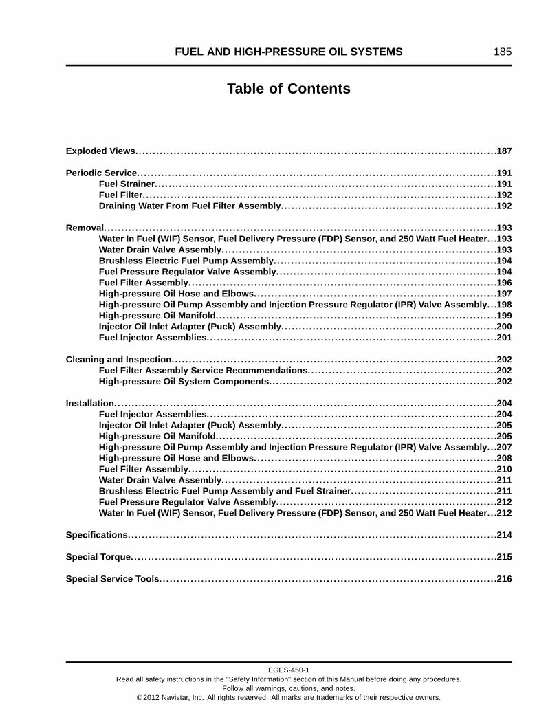
FUEL AND HIGH-PRESSURE OIL SYSTEMS 185
Table of Contents
Exploded Views.. . . . . . . . . . . . . . . . . . . . . . . . . . . . . . . . . . . . . . . . . . . . . . . . . . . . . . . . . . . . . . . . . . . . . . . . . . . . . . . . . . . . . . . . . . . . . . . . . . . . . . .187
Periodic Service. . . . . . . . . . . . . . . . . . . . . . . . . . . . . . . . . . . . . . . . . . . . . . . . . . . . . . . . . . . . . . . . . . . . . . . . . . . . . . . . . . . . . . . . . . . . . . . . . . . . . . . .191Fuel Strainer. . . . . . . . . . . . . . . . . . . . . . . . . . . . . . . . . . . . . . . . . . . . . . . . . . . . . . . . . . . . . . . . . . . . . . . . . . . . . . . . . . . . . . . . . . . . . . . . . . .191Fuel Filter. . . . . . . . . . . . . . . . . . . . . . . . . . . . . . . . . . . . . . . . . . . . . . . . . . . . . . . . . . . . . . . . . . . . . . . . . . . . . . . . . . . . . . . . . . . . . . . . . . . . . .192Draining Water From Fuel Filter Assembly. . . . . . . . . . . . . . . . . . . . . . . . . . . . . . . . . . . . . . . . . . . . . . . . . . . . . . . . . . . . . .192
Removal. . . . . . . . . . . . . . . . . . . . . . . . . . . . . . . . . . . . . . . . . . . . . . . . . . . . . . . . . . . . . . . . . . . . . . . . . . . . . . . . . . . . . . . . . . . . . . . . . . . . . . . . . . . . . . . . .193Water In Fuel (WIF) Sensor, Fuel Delivery Pressure (FDP) Sensor, and 250 Watt Fuel Heater. . .193Water Drain Valve Assembly. . . . . . . . . . . . . . . . . . . . . . . . . . . . . . . . . . . . . . . . . . . . . . . . . . . . . . . . . . . . . . . . . . . . . . . . . . . . . . .193Brushless Electric Fuel Pump Assembly. . . . . . . . . . . . . . . . . . . . . . . . . . . . . . . . . . . . . . . . . . . . . . . . . . . . . . . . . . . . . . . .194Fuel Pressure Regulator Valve Assembly. . . . . . . . . . . . . . . . . . . . . . . . . . . . . . . . . . . . . . . . . . . . . . . . . . . . . . . . . . . . . . . .194Fuel Filter Assembly. . . . . . . . . . . . . . . . . . . . . . . . . . . . . . . . . . . . . . . . . . . . . . . . . . . . . . . . . . . . . . . . . . . . . . . . . . . . . . . . . . . . . . . . .196High-pressure Oil Hose and Elbows. . . . . . . . . . . . . . . . . . . . . . . . . . . . . . . . . . . . . . . . . . . . . . . . . . . . . . . . . . . . . . . . . . . . . .197High-pressure Oil Pump Assembly and Injection Pressure Regulator (IPR) Valve Assembly. . .198High-pressure Oil Manifold. . . . . . . . . . . . . . . . . . . . . . . . . . . . . . . . . . . . . . . . . . . . . . . . . . . . . . . . . . . . . . . . . . . . . . . . . . . . . . . . .199Injector Oil Inlet Adapter (Puck) Assembly. . . . . . . . . . . . . . . . . . . . . . . . . . . . . . . . . . . . . . . . . . . . . . . . . . . . . . . . . . . . . .200Fuel Injector Assemblies. . . . . . . . . . . . . . . . . . . . . . . . . . . . . . . . . . . . . . . . . . . . . . . . . . . . . . . . . . . . . . . . . . . . . . . . . . . . . . . . . . . .201
Cleaning and Inspection. . . . . . . . . . . . . . . . . . . . . . . . . . . . . . . . . . . . . . . . . . . . . . . . . . . . . . . . . . . . . . . . . . . . . . . . . . . . . . . . . . . . . . . . . . . . . .202Fuel Filter Assembly Service Recommendations. . . . . . . . . . . . . . . . . . . . . . . . . . . . . . . . . . . . . . . . . . . . . . . . . . . . . .202High-pressure Oil System Components. . . . . . . . . . . . . . . . . . . . . . . . . . . . . . . . . . . . . . . . . . . . . . . . . . . . . . . . . . . . . . . . . .202
Installation. . . . . . . . . . . . . . . . . . . . . . . . . . . . . . . . . . . . . . . . . . . . . . . . . . . . . . . . . . . . . . . . . . . . . . . . . . . . . . . . . . . . . . . . . . . . . . . . . . . . . . . . . . . . . .204Fuel Injector Assemblies. . . . . . . . . . . . . . . . . . . . . . . . . . . . . . . . . . . . . . . . . . . . . . . . . . . . . . . . . . . . . . . . . . . . . . . . . . . . . . . . . . . .204Injector Oil Inlet Adapter (Puck) Assembly. . . . . . . . . . . . . . . . . . . . . . . . . . . . . . . . . . . . . . . . . . . . . . . . . . . . . . . . . . . . . .205High-pressure Oil Manifold. . . . . . . . . . . . . . . . . . . . . . . . . . . . . . . . . . . . . . . . . . . . . . . . . . . . . . . . . . . . . . . . . . . . . . . . . . . . . . . . .205High-pressure Oil Pump Assembly and Injection Pressure Regulator (IPR) Valve Assembly. . .207High-pressure Oil Hose and Elbows. . . . . . . . . . . . . . . . . . . . . . . . . . . . . . . . . . . . . . . . . . . . . . . . . . . . . . . . . . . . . . . . . . . . . .208Fuel Filter Assembly. . . . . . . . . . . . . . . . . . . . . . . . . . . . . . . . . . . . . . . . . . . . . . . . . . . . . . . . . . . . . . . . . . . . . . . . . . . . . . . . . . . . . . . . .210Water Drain Valve Assembly. . . . . . . . . . . . . . . . . . . . . . . . . . . . . . . . . . . . . . . . . . . . . . . . . . . . . . . . . . . . . . . . . . . . . . . . . . . . . . .211Brushless Electric Fuel Pump Assembly and Fuel Strainer. . . . . . . . . . . . . . . . . . . . . . . . . . . . . . . . . . . . . . . . . .211Fuel Pressure Regulator Valve Assembly. . . . . . . . . . . . . . . . . . . . . . . . . . . . . . . . . . . . . . . . . . . . . . . . . . . . . . . . . . . . . . . .212Water In Fuel (WIF) Sensor, Fuel Delivery Pressure (FDP) Sensor, and 250 Watt Fuel Heater. . .212
Specifications. . . . . . . . . . . . . . . . . . . . . . . . . . . . . . . . . . . . . . . . . . . . . . . . . . . . . . . . . . . . . . . . . . . . . . . . . . . . . . . . . . . . . . . . . . . . . . . . . . . . . . . . . .214
Special Torque.. . . . . . . . . . . . . . . . . . . . . . . . . . . . . . . . . . . . . . . . . . . . . . . . . . . . . . . . . . . . . . . . . . . . . . . . . . . . . . . . . . . . . . . . . . . . . . . . . . . . . . . . .215
Special Service Tools. . . . . . . . . . . . . . . . . . . . . . . . . . . . . . . . . . . . . . . . . . . . . . . . . . . . . . . . . . . . . . . . . . . . . . . . . . . . . . . . . . . . . . . . . . . . . . . . .216
EGES-450-1Read all safety instructions in the "Safety Information" section of this Manual before doing any procedures.
Follow all warnings, cautions, and notes.©2012 Navistar, Inc. All rights reserved. All marks are trademarks of their respective owners.
186 FUEL AND HIGH-PRESSURE OIL SYSTEMS
EGES-450-1Read all safety instructions in the "Safety Information" section of this Manual before doing any procedures.
Follow all warnings, cautions, and notes.©2012 Navistar, Inc. All rights reserved. All marks are trademarks of their respective owners.
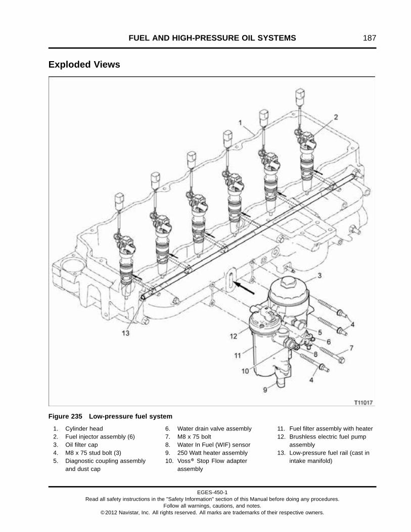
FUEL AND HIGH-PRESSURE OIL SYSTEMS 187
Exploded Views
Figure 235 Low-pressure fuel system
1. Cylinder head2. Fuel injector assembly (6)3. Oil filter cap4. M8 x 75 stud bolt (3)5. Diagnostic coupling assembly
and dust cap
6. Water drain valve assembly7. M8 x 75 bolt8. Water In Fuel (WIF) sensor9. 250 Watt heater assembly10. Voss® Stop Flow adapter
assembly
11. Fuel filter assembly with heater12. Brushless electric fuel pump
assembly13. Low-pressure fuel rail (cast in
intake manifold)
EGES-450-1Read all safety instructions in the "Safety Information" section of this Manual before doing any procedures.
Follow all warnings, cautions, and notes.©2012 Navistar, Inc. All rights reserved. All marks are trademarks of their respective owners.

188 FUEL AND HIGH-PRESSURE OIL SYSTEMS
Figure 236 Fuel filter assembly with heater
1. M5 x 25, pump cover screw (3)2. Brushless electric fuel pump
assembly3. Pump cover and housing O-ring
(2)4. Fuel pump adapter5. Fuel pump O-ring6. Pump strainer7. M6 screw (3)8. Port cover9. Port cover seal10. Oil (fuel) filter cap11. O-ring gasket12. Fuel element13. Irregular molded gasket
14. Fuel filter with heater housingassembly
15. M8 x 75 stud bolt (3)16. Fuel pressure regulator valve
assembly17. Fuel pressure regulator valve
spring18. Cover plate seal19. Bottom cover plate20. Sensor O-ring21. Fuel Delivery Pressure (FDP)
sensor22. M6 screw (7)23. O-ring24. Water drain valve assembly
25. M5 x 27 Torx® screw (2)26. O-ring seal27. Water In Fuel (WIF) sensor28. 250 watt fuel heater assembly
(optional)29. Heater O-ring gasket30. Dust cap31. Diagnostic coupling32. O-ring33. M8 x 75 bolt34. Voss® stop flow adapter (fuel
inlet)35. Hand primer gasket
EGES-450-1Read all safety instructions in the "Safety Information" section of this Manual before doing any procedures.
Follow all warnings, cautions, and notes.©2012 Navistar, Inc. All rights reserved. All marks are trademarks of their respective owners.

FUEL AND HIGH-PRESSURE OIL SYSTEMS 189
Figure 237 High-pressure Oil System
1. Engine Compression BrakePressure (ECBP) sensor
2. Sensor O-ring (2)3. Engine Compression Brake
(ECB) valve4. Injection Control Pressure (ICP)
sensor
5. High-pressure oil manifold6. Injector oil inlet from
high-pressure oil manifold7. Oil outlet (2)8. Fuel inlet port (4)9. 70 degree adapter elbow
assembly
10. High-pressure oil hose11. Injection Pressure Regulator
(IPR) valve assembly12. Oil inlet from front oil cover
reservoir13. High-pressure pump assembly14. Fuel injector assembly (6)
EGES-450-1Read all safety instructions in the "Safety Information" section of this Manual before doing any procedures.
Follow all warnings, cautions, and notes.©2012 Navistar, Inc. All rights reserved. All marks are trademarks of their respective owners.

190 FUEL AND HIGH-PRESSURE OIL SYSTEMS
Figure 238 High-pressure pump
1. High-pressure 12cc pump2. M8 x 100 bolt (2)3. O-ring seal (#112) (2)4. Back-up ring5. Elbow jam nut6. 90 degree adapter elbow
7. Injection Pressure Regulator(IPR) valve assembly
8. O-ring seal9. PTFE OE profile seal10. O-ring seal (#13)11. Back-up ring seal
12. O-ring seal13. M8 x 30 bolt (2)14. Inlet filter15. Pump gear16. M14 x 1.5 left bolt17. High-pressure pump gasket
EGES-450-1Read all safety instructions in the "Safety Information" section of this Manual before doing any procedures.
Follow all warnings, cautions, and notes.©2012 Navistar, Inc. All rights reserved. All marks are trademarks of their respective owners.
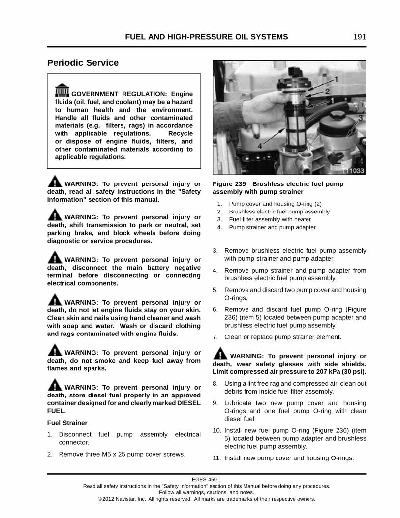
FUEL AND HIGH-PRESSURE OIL SYSTEMS 191
Periodic Service
GOVERNMENT REGULATION: Enginefluids (oil, fuel, and coolant) may be a hazardto human health and the environment.Handle all fluids and other contaminatedmaterials (e.g. filters, rags) in accordancewith applicable regulations. Recycleor dispose of engine fluids, filters, andother contaminated materials according toapplicable regulations.
WARNING: To prevent personal injury ordeath, read all safety instructions in the "SafetyInformation" section of this manual.
WARNING: To prevent personal injury ordeath, shift transmission to park or neutral, setparking brake, and block wheels before doingdiagnostic or service procedures.
WARNING: To prevent personal injury ordeath, disconnect the main battery negativeterminal before disconnecting or connectingelectrical components.
WARNING: To prevent personal injury ordeath, do not let engine fluids stay on your skin.Clean skin and nails using hand cleaner and washwith soap and water. Wash or discard clothingand rags contaminated with engine fluids.
WARNING: To prevent personal injury ordeath, do not smoke and keep fuel away fromflames and sparks.
WARNING: To prevent personal injury ordeath, store diesel fuel properly in an approvedcontainer designed for and clearly marked DIESELFUEL.
Fuel Strainer
1. Disconnect fuel pump assembly electricalconnector.
2. Remove three M5 x 25 pump cover screws.
Figure 239 Brushless electric fuel pumpassembly with pump strainer
1. Pump cover and housing O-ring (2)2. Brushless electric fuel pump assembly3. Fuel filter assembly with heater4. Pump strainer and pump adapter
3. Remove brushless electric fuel pump assemblywith pump strainer and pump adapter.
4. Remove pump strainer and pump adapter frombrushless electric fuel pump assembly.
5. Remove and discard two pump cover and housingO-rings.
6. Remove and discard fuel pump O-ring (Figure236) (item 5) located between pump adapter andbrushless electric fuel pump assembly.
7. Clean or replace pump strainer element.
WARNING: To prevent personal injury ordeath, wear safety glasses with side shields.Limit compressed air pressure to 207 kPa (30 psi).
8. Using a lint free rag and compressed air, clean outdebris from inside fuel filter assembly.
9. Lubricate two new pump cover and housingO-rings and one fuel pump O-ring with cleandiesel fuel.
10. Install new fuel pump O-ring (Figure 236) (item5) located between pump adapter and brushlesselectric fuel pump assembly.
11. Install new pump cover and housing O-rings.
EGES-450-1Read all safety instructions in the "Safety Information" section of this Manual before doing any procedures.
Follow all warnings, cautions, and notes.©2012 Navistar, Inc. All rights reserved. All marks are trademarks of their respective owners.

192 FUEL AND HIGH-PRESSURE OIL SYSTEMS
12. Install new or cleaned pump strainer and pumpadapter onto brushless electric fuel pumpassembly.
13. Install brushless electric fuel pump assembly intofuel filter assembly with heater.
14. Install three M5 x 25 pump cover screws andtighten to special torque (page 215). Do not overtighten pump cover screws.
15. Turn ignition key ON to pressurize fuel system.Inspect area around top of electric fuel pump forfuel leaks. Turn ignition key OFF and repair leaksas needed.
Fuel Filter
Figure 240 Fuel filter assembly (with optionalheater)
1. Fuel filter cap2. O-ring gasket3. Fuel element
WARNING: To prevent personal injury ordeath, do not smoke and keep fuel away fromflames and sparks.
1. Open water drain valve and drain fuel into acorrect container clearly marked DIESEL FUEL.Dispose of diesel fuel according to applicableregulations.
2. Remove fuel filter cap from fuel filter assembly.
3. Remove and discard O-ring gasket.
4. Pull fuel element up and out of fuel filter assemblyand dispose of fuel element according toapplicable regulations.
5. Clean seal areas. Lubricate new O-ring gasketwith clean diesel fuel and install on oil filter cap.
6. Clean out debris from inside fuel filter assembly.
7. Install a new fuel element into fuel filter assembly.
8. Lubricate oil filter cap threads with clean dieselfuel.
9. Tighten fuel filter cap to special torque (page 215).
10. Turn ignition key ON to pressurize fuel system.Inspect area around fuel filter cap for fuel leaks.Turn ignition key OFF and repair leaks as needed.
Draining Water From Fuel Filter Assembly
WARNING: To prevent personal injury ordeath, do not smoke and keep fuel away fromflames and sparks.
1. Open water drain valve (Figure 245) (item 8) anddrain water from fuel filter assembly into containerclearly marked DIESEL FUEL. Close water drainvalve when all water is drained and a solid streamof fuel runs out of drain valve. Dispose of waterand diesel fuel mixture according to applicableregulations.
2. Turn ignition key ON to pressurize fuel system.Inspect drain valve area for fuel leaks. Turnignition key OFF and repair leaks as needed.
EGES-450-1Read all safety instructions in the "Safety Information" section of this Manual before doing any procedures.
Follow all warnings, cautions, and notes.©2012 Navistar, Inc. All rights reserved. All marks are trademarks of their respective owners.

FUEL AND HIGH-PRESSURE OIL SYSTEMS 193
RemovalWater In Fuel (WIF) Sensor, Fuel DeliveryPressure (FDP) Sensor, and 250 Watt Fuel Heater
Figure 241 Fuel filter assembly with heater (ifequipped)
1. Water in fuel (WIF) sensor2. Fuel delivery pressure (FDP) sensor3. 250 Watt fuel heater (optional)4. M6 screw (2)
1. If equipped, disconnect engine harness connectorfrom 250 watt fuel heater.
2. Disconnect engine harness connector from WIFsensor.
3. Disconnect 3-pin engine harness connector fromFDP sensor.
WARNING: To prevent personal injury ordeath, do not smoke and keep fuel away fromflames and sparks.
4. Open water drain valve and drain fuel into acorrect container clearly marked DIESEL FUEL.Dispose of diesel fuel according to applicableregulations.
5. Remove WIF sensor.
6. Remove and discard WIF sensor O-ring.
7. Remove FDP sensor.
8. Remove and discard FDP sensor O-ring.
9. Disconnect fuel inlet line and drain fuel into acorrect container clearly marked DIESEL FUEL.Dispose of diesel fuel according to applicableregulations.
NOTE: Skip steps 10 and 11 if not equipped with 250watt fuel heater.
10. Remove two M6 screws with a T30 Torx® bit(page 216).
11. Pull 250 watt fuel heater down to remove, anddiscard O-ring.
Water Drain Valve Assembly
Figure 242 Water drain valve assembly and fuelfilter assembly (with heater shown)
1. Fuel filter assembly (with optional heater)2. O-ring3. Drain stem4. Drain retainer5. M5 screws (2)
WARNING: To prevent personal injury ordeath, do not smoke and keep fuel away fromflames and sparks.
1. Open water drain valve and drain fuel into acorrect container clearly marked DIESEL FUEL.Dispose of diesel fuel according to applicableregulations.
EGES-450-1Read all safety instructions in the "Safety Information" section of this Manual before doing any procedures.
Follow all warnings, cautions, and notes.©2012 Navistar, Inc. All rights reserved. All marks are trademarks of their respective owners.

194 FUEL AND HIGH-PRESSURE OIL SYSTEMS
2. Remove two M5 screws using a T27 Torx® bit(page 216).
3. Remove drain retainer, drain stem, and O-ringfrom fuel filter assembly.
4. Discard O-ring.
Brushless Electric Fuel Pump Assembly
1. Remove three M5 x 25 pump cover screwssecuring brushless electric fuel pump assemblyto fuel filter assembly.
Figure 243 Brushless electric fuel pumpassembly and fuel strainer
1. Pump cover and housing O-ring (2)2. Brushless electric fuel pump assembly3. Fuel filter assembly with heater4. Pump strainer and pump adapter
2. Remove fuel pump and fuel strainer assembly.
3. Pull pump strainer and pump adapter frombrushless electric fuel pump assembly.
4. Remove and discard two pump cover and housingO-rings.
5. Remove and discard fuel pump O-ring (Figure236) (item 5) located between pump adapter andbrushless electric fuel pump assembly.
Fuel Pressure Regulator Valve Assembly
Figure 244 Fuel pressure regulator valveassembly and cover plate
1. Fuel filter assembly2. Fuel pressure regulator valve assembly3. Fuel pressure regulator valve spring4. Cover plate seal5. Bottom cover plate6. M6 screw (5)7. Fuel Delivery Pressure (FDP) sensor
WARNING: To prevent personal injury ordeath, do not smoke and keep fuel away fromflames and sparks.
1. Place a suitable container below fuel filterassembly. Open water drain valve and drainfuel into container. Close drain valve when fuel isdrained.
EGES-450-1Read all safety instructions in the "Safety Information" section of this Manual before doing any procedures.
Follow all warnings, cautions, and notes.©2012 Navistar, Inc. All rights reserved. All marks are trademarks of their respective owners.

FUEL AND HIGH-PRESSURE OIL SYSTEMS 195
2. Using a T30 Torx® bit (page 216), remove five M6screws while holding cover plate in place.
3. Remove bottom cover plate downward so fuelpressure regulator valve assembly and fuelpressure regulator valve spring remain in bottomcover plate. Ensure excess fuel drains intocontainer.
4. Remove and discard fuel pressure regulator valvecover plate seal.
5. Remove all dirt and debris from fuel pressureregulator valve seating area.
6. Clean sealing areas on fuel filter assembly andbottom cover plate.
7. Check for damage in regulator seating area of fuelfilter assembly and bottom cover plate.
8. Dispose of diesel fuel according to applicableregulations.
EGES-450-1Read all safety instructions in the "Safety Information" section of this Manual before doing any procedures.
Follow all warnings, cautions, and notes.©2012 Navistar, Inc. All rights reserved. All marks are trademarks of their respective owners.

196 FUEL AND HIGH-PRESSURE OIL SYSTEMS
Fuel Filter Assembly
Figure 245 Fuel filter assembly (with heater shown)
1. M8 x 75 bolt2. Dust cap and diagnostic coupling3. M8 x 75 stud bolt (3)4. M6 x 16 bolt (hidden from view)
5. M8 oil filler tube support nut (2)6. Oil filler tube support7. Fuel outlet fitting (return to tank)8. Water drain valve assembly
9. 250 Watt fuel heater (optional)10. Voss® Stop Flow adapter
assembly (from tank)
WARNING: To prevent personal injury ordeath, do not smoke and keep fuel away fromflames and sparks.
1. Open water drain valve and drain fuel into acorrect container clearly marked DIESEL FUEL.Dispose of diesel fuel according to applicableregulations.
2. Disconnect fuel inlet and return lines from fuelfilter assembly.
3. Remove oil level gauge assembly. Refer to OilLevel Gauge Assembly (page 450).
4. Disconnect WIF sensor, if equipped, 250 watt fuelheater, and FDP engine harness connectors.
5. Remove two M8 nuts and one M6 x 16 boltsecuring engine oil filler tube support to fuel filterassembly.
6. Remove three M8 x 75 stud bolts and one M8 x75 bolt securing the fuel filter assembly to intakemanifold and remove fuel filter assembly.
7. If damaged or leaking, remove Voss® Stop Flowadapter assembly from fuel filter assembly.
8. If damaged or leaking, remove diagnosticcoupling assembly from fuel filter assembly.
EGES-450-1Read all safety instructions in the "Safety Information" section of this Manual before doing any procedures.
Follow all warnings, cautions, and notes.©2012 Navistar, Inc. All rights reserved. All marks are trademarks of their respective owners.

FUEL AND HIGH-PRESSURE OIL SYSTEMS 197
9. Remove and discard irregular molded gasket frombetween fuel filter assembly and intake manifold.
10. If necessary, remove three M6 screws, port coverand port cover seal (Figure 236) (items 7, 8, and9).
High-pressure Oil Hose and Elbows
Figure 246 High-pressure oil hose
1. High-pressure oil hose2. Elbow jam nut (2)3. 70 degree adapter elbow
4. Swivel nut (2)5. 90 degree adapter elbow6. High-pressure pump assembly
7. High-pressure oil hose nut (2)
1. Remove high-pressure oil hose swivel nuts from70 and 90 degree adapter elbows. Use onewrench to hold high-pressure oil hose nut in place
while loosening its corresponding swivel nut usinganother wrench. Remove high-pressure oil hose.
EGES-450-1Read all safety instructions in the "Safety Information" section of this Manual before doing any procedures.
Follow all warnings, cautions, and notes.©2012 Navistar, Inc. All rights reserved. All marks are trademarks of their respective owners.

198 FUEL AND HIGH-PRESSURE OIL SYSTEMS
Figure 247 High-pressure oil elbow (typical)
1. O-ring seal (#112) (2)2. Back-up ring3. Elbow jam nut4. Adapter elbow
2. Loosen elbow jam nuts on each adapter elbow.
3. Remove 70 and 90 degree adapter elbows.
4. Remove and discard each elbow back-up ring andO-rings.
NOTE: See Intake Manifold, Fuel Valve, and FuelRail Plugs (page 176) for fuel valve and fuel rail plugremoval.
High-pressure Oil Pump Assembly and InjectionPressure Regulator (IPR) Valve Assembly
Figure 248 High-pressure pump assembly
1. M8 x 100 bolt (2)2. IPR valve3. M8 x 30 bolt (2)
1. Using IPR Socket (page 216), remove IPR valve.
Figure 249 IPR valve O-rings and back-up rings
1. O-ring seal (valve tip)2. Back-up ring seal (valve tip)3. O-ring seal (#13)4. PTFE OE profile seal5. O-ring seal (IPR valve sealing)
2. Remove and discard IPR valve O-rings andback-up rings.
3. Remove two M8 x 100 and two M8 x 30 boltssecuring high-pressure oil pump assembly to frontcover.
4. Remove high-pressure pump assembly anddiscard high-pressure pump assembly gasket.
EGES-450-1Read all safety instructions in the "Safety Information" section of this Manual before doing any procedures.
Follow all warnings, cautions, and notes.©2012 Navistar, Inc. All rights reserved. All marks are trademarks of their respective owners.

FUEL AND HIGH-PRESSURE OIL SYSTEMS 199
Figure 250 Pump gear and inlet filter
1. M14 x 1.5 left bolt2. High-pressure oil pump assembly3. Pump gear4. Inlet filter
5. Remove and discard inlet filter.
6. If required, remove pump gear by rotating M14 x1.5 left bolt clockwise (this bolt has left handedthreads).
High-pressure Oil Manifold
1. Remove valve cover (page 336).
Figure 251 Valve cover gasket (injector harness)
1. Injector 1 connector2. Injector 2 connector3. Injector 3 connector4. Injector 4 connector5. Injector 5 connector6. Injector 6 connector7. Injection Control Pressure (ICP) sensor connector
2. Disconnect six injector connectors and ICPsensor connector.
3. Disconnect optional Engine Compression BrakePressure (ECBP) sensor (page 223) and EngineCompression Brake (ECB) valve connector.(page 223)
4. Remove valve cover gasket (injector harness).Starting at one side, lightly pry up and open eachof the six wire channel retainers while gentlypulling up to remove harness from cylinder head.
EGES-450-1Read all safety instructions in the "Safety Information" section of this Manual before doing any procedures.
Follow all warnings, cautions, and notes.©2012 Navistar, Inc. All rights reserved. All marks are trademarks of their respective owners.

200 FUEL AND HIGH-PRESSURE OIL SYSTEMS
Figure 252 High-pressure oil manifold(non-brake)
1. High-pressure oil manifold2. M8 x 90 bolt (12)
5. Use hand tools to break loose twelve M8 x90 bolts securing high-pressure oil manifold tocylinder head. Remove twelve bolts.
WARNING: To prevent personal injury ordeath, get assistance to remove and install thehigh-pressure oil manifold assembly.
6. Lift high-pressure oil manifold up just enough todrain oil out of manifold before lifting it away fromcylinder head.
7. Lift up and remove high-pressure oil manifold fromengine.
8. Remove and discard injector oil inlet adapterseals and back-up rings (Figure 253) (items 2and 3).
9. Remove and discard oil inlet O-ring (page201) (Figure 254) (item 3).
10. Install Injector Oil Inlet Plugs (page 216) oninjectors to keep dirt out.
Injector Oil Inlet Adapter (Puck) Assembly
Figure 253 Injector oil inlet adapter installed inhigh-pressure oil manifold
1. Injector oil inlet adapter2. Backup ring3. Injector oil inlet seal4. Oil inlet tube5. Internal O-ring (not visible, not serviceable)
See Cleaning and Inspection (page 202) procedure toinspect the oil inlet adapter for damage. If damaged,remove injector oil inlet adapter assemblies usingHigh Pressure Rail Adapter Socket (page 216).
EGES-450-1Read all safety instructions in the "Safety Information" section of this Manual before doing any procedures.
Follow all warnings, cautions, and notes.©2012 Navistar, Inc. All rights reserved. All marks are trademarks of their respective owners.

FUEL AND HIGH-PRESSURE OIL SYSTEMS 201
Fuel Injector Assemblies
Figure 254 Fuel injector assemblies and oil inletO-ring (typical)
1. Fuel injector (6)2. Injector hold down clamp assembly (6)3. Oil inlet O-ring (high-pressure)
CAUTION: To prevent engine damage, do not usepower tools to remove or install fuel injector clampbolts. Threads will be damaged if a bolt or nut isrotated too quickly.
NOTE: Fuel injectors are self extracting and come outof injector bores as injector hold down clamp bolt isloosened.
1. Using Fuel Injector Remover Tool (T40) (page216), extract six injector hold down clamps andinjectors by removing injector clamp bolt.
CAUTION: To prevent engine damage, do not cleaninjectors with parts solvent or other chemicals.
NOTE: If nozzle gasket is missing from any injectorremoved, look for gasket at bottom of its injector bore.Remove and discard all nozzle gaskets.
Figure 255 Fuel injector assembly
1. Upper O-ring2. Lower O-ring3. Nozzle gasket4. Injector nozzle5. Fuel inlet port
2. Remove and discard injector upper and lowerO-rings and nozzle gasket with a non-metallichand tool.
CAUTION: To prevent engine damage, when injectorsare removed from the engine, place injectors in acloseable container, cover with clean engine oil, andclose container.
3. Place injectors in a sealable container, cover withclean engine oil, and close container.
EGES-450-1Read all safety instructions in the "Safety Information" section of this Manual before doing any procedures.
Follow all warnings, cautions, and notes.©2012 Navistar, Inc. All rights reserved. All marks are trademarks of their respective owners.

202 FUEL AND HIGH-PRESSURE OIL SYSTEMS
Cleaning and Inspection
WARNING: To prevent personal injury ordeath, wear safety glasses with side shields.Limit compressed air pressure to 207 kPa (30 psi).
Fuel Filter Assembly Service Recommendations
NOTE: Refer to (Figure 235) and (Figure 236).
Disassembly of the fuel filter assembly is not normallyrecommended beyond service of the following:
• Fuel element replacement
• Pump strainer cleaning or replacement
• Sensor or 250 watt fuel heater assemblyreplacement
• Diagnostic coupling assembly cleaning orreplacement
• Water drain valve assembly cleaning orreplacement
• Electric fuel pump replacement
• Fuel pressure regulator cleaning or replacement
Disassemble or replace fuel filter assembly to correctthe following problems:
• Contaminated fuel in engine
• Fuel or air leaks of the brushless electric fuelpump assembly
1. Clean fuel filter assembly using a suitablenon-caustic solvent.
2. Inspect fuel filter assembly for cracks and leaks.Replace cracked or leaking parts if necessary.
High-pressure Oil System Components
1. Clean high-pressure oil manifold, IPR valveoutside of high-pressure oil pump with a suitablenon-caustic solvent.
2. Blow parts dry using filtered compressed air.
3. Inspect high-pressure oil pump assembly,high-pressure oil hose, and high-pressure oilmanifold for cracks and leaks. Replace crackedor leaking parts.
Figure 256 Injector oil inlet adapter installed inhigh-pressure oil manifold
1. Injector oil inlet adapter2. Backup ring3. Injector oil inlet seal4. Oil outlet tube5. Internal O-ring (not serviceable)
4. Verify six injector oil inlet adapter oil inlet tubesmove and are not frozen. Inspect injector oil inletadapters for internal O-ring extrusion (betweenadapter and oil outlet tube). Replace any adapterwhich has an extruded internal O-ring, frozen oilinlet tube, or high-pressure oil leak path.
5. Check IPR valve O-ring seal grooves for erosionor other damage. Replace IPR valve if eroded ordamaged.
6. Check IPR valve inlet screen for restrictions.Clean or replace valve as necessary.
NOTE: Fuel injectors should be checked forcarbon/soot traces between the lower injector O-ring(Figure 257) (item 2) and the nozzle gasket (Figure257) (item 3). When removed, the injectors shouldbe clean and shiny, looking like new except for thenozzle. Carbon on these areas may mean thatcompression leaked through the nozzle gasket dueto a loose injector. Mistakenly doubling the nozzlegasket, or poor sealing surfaces may cause looseinjectors.
7. Inspect intake manifold and fuel injectors forcracks and leaks. Replace cracked or leakingparts.
EGES-450-1Read all safety instructions in the "Safety Information" section of this Manual before doing any procedures.
Follow all warnings, cautions, and notes.©2012 Navistar, Inc. All rights reserved. All marks are trademarks of their respective owners.
FUEL AND HIGH-PRESSURE OIL SYSTEMS 203
8. Inspect all fuel lines for kinks, obstructions, orother damage. Replace fuel lines if necessary.
9. Check high-pressure pump inlet screen forrestrictions. Clean or replace high-pressurepump inlet screen as necessary.
10. Clean injector and high-pressure oil manifoldthreaded holes. Oil in these holes will negativelyaffect bolt torque and result in engine performanceissues.
EGES-450-1Read all safety instructions in the "Safety Information" section of this Manual before doing any procedures.
Follow all warnings, cautions, and notes.©2012 Navistar, Inc. All rights reserved. All marks are trademarks of their respective owners.

204 FUEL AND HIGH-PRESSURE OIL SYSTEMS
InstallationFuel Injector Assemblies
Figure 257 Fuel Injector assembly
1. Upper O-ring2. Lower O-ring3. Nozzle gasket4. Fuel nozzle5. Fuel inlet port
CAUTION: To prevent engine damage, replace upperand lower injector O-rings and nozzle gasket eachtime an injector is removed.
1. Lubricate new injector upper O-ring with cleanengine oil and slide into the recess just above thefuel inlet ports.
2. Lubricate new lower O-ring with clean engine oiland slide into the recess just below the fuel inletports.
Figure 258 Injector nozzle gasket
1. Injector nozzle gasket2. Injector nozzle
CAUTION: To prevent engine damage, do not nick orscratch injector nozzle gasket.
3. Push a new injector nozzle gasket oninjector nozzle by hand. Nozzle gasketsare non-directional and can be installed witheither face out. Verify that old nozzle gaskets arenot left at bottom of injector cup.
EGES-450-1Read all safety instructions in the "Safety Information" section of this Manual before doing any procedures.
Follow all warnings, cautions, and notes.©2012 Navistar, Inc. All rights reserved. All marks are trademarks of their respective owners.

FUEL AND HIGH-PRESSURE OIL SYSTEMS 205
Figure 259 Injector assembly installation(typical)
1. Injector hold down clamp notch2. Oil inlet O-ring (high-pressure)3. Injector assembly slot
4. Using a suction bulb (page 216), purge any oil orfuel that may have dripped in during removal ofinjectors.
5. Align each injector assembly slot with hold downclamp notch and install assembly in cylinder head.
CAUTION: To prevent engine damage, do not usepower tools to remove or install fuel injector clampbolts. Threads will be damaged if a bolt or nut isrotated too quickly.
6. Using Fuel Injector Remover Tool (T40) (page216), tighten injector hold down clamp bolts.Make sure injector and hold down clamp areinstalled squarely as bolt is tightened.
7. Tighten six injector hold down clamp bolts tospecial torque (page 215). Injector will be placedat correct depth.
Injector Oil Inlet Adapter (Puck) Assembly
Figure 260 Injector oil inlet adapter installed inhigh-pressure oil manifold
1. Injector oil inlet adapter2. Backup ring3. Injector oil inlet seal4. Oil inlet tube5. Internal O-ring (not serviceable)
1. Install injector oil inlet adapters using HighPressure Rail Adapter Socket (page 216).
2. Tighten injector oil inlet adapters to special torque(page 215).
High-pressure Oil Manifold
NOTE: Air trapped in high-pressure oil manifold willbe purged automatically during cranking and start up.
1. If not previously done, verify six injector oilinlet adapter oil inlet tubes move and are notfrozen. Inspect injector oil inlet adapters forinternal O-ring extrusion and high-pressure oilleak paths. Replace any adapter which has anextruded internal O-ring, frozen oil inlet tube, orhigh-pressure oil leak path (identify during highpressure oil diagnostics).
2. Coat backup rings and injector oil inlet seals withclean engine oil.
3. Install new backup rings and injector oil inlet sealson all oil inlet adapters that were not replaced withnew.
EGES-450-1Read all safety instructions in the "Safety Information" section of this Manual before doing any procedures.
Follow all warnings, cautions, and notes.©2012 Navistar, Inc. All rights reserved. All marks are trademarks of their respective owners.

206 FUEL AND HIGH-PRESSURE OIL SYSTEMS
4. Coat a new oil inlet O-ring (Figure 259) with cleanengine oil and install in cylinder head recess.
Figure 261 High-pressure oil manifoldinstallation
WARNING: To prevent personal injury ordeath, get assistance to remove and install thehigh-pressure oil manifold assembly.
5. With help from an assistant, lift high-pressure oilmanifold up and carefully place on engine.
CAUTION: To prevent engine damage, carefully alignsix injector oil inlet ports with six injector oil inletadapters of the high-pressure oil manifold beforetightening oil manifold bolts.
6. Carefully align six injector oil inlet ports with sixinjector oil inlet adapters of the high-pressure oilmanifold and firmly push down to “snap” manifoldin place. Confirm that manifold is seated againstcylinder head at all contact points between thetwo.
Figure 262 High-pressure oil manifold (typical)
1. High-pressure oil manifold2. M8 x 90 bolt (12)
7. Install and finger tighten twelve M8 x 90 boltssecuring high-pressure oil manifold to cylinderhead.
Figure 263 High-pressure oil manifold bolttorque sequence
8. Tighten twelve M8 x 90 bolts to 30 N·m (22 lbf·ft)in the torque sequence shown.
EGES-450-1Read all safety instructions in the "Safety Information" section of this Manual before doing any procedures.
Follow all warnings, cautions, and notes.©2012 Navistar, Inc. All rights reserved. All marks are trademarks of their respective owners.

FUEL AND HIGH-PRESSURE OIL SYSTEMS 207
High-pressure Oil Pump Assembly and InjectionPressure Regulator (IPR) Valve Assembly
Figure 264 Pump gear and inlet filter
1. M14 x 1.5 left bolt2. High-pressure pump assembly3. Pump gear4. Inlet filter
1. If removed, position pump gear ontohigh-pressure pump and install M14 x 1.5left bolt. Tighten to special torque (page 215).
2. Install a new inlet filter.
3. Lubricate a new high-pressure pump gasket withclean engine oil and install on rear of front coverassembly.
4. Install high-pressure pump assembly into frontcover, making sure pump gear meshes with upperidler gear.
Figure 265 High-pressure pump assembly
1. M8 x 100 bolt (2)2. IPR valve3. M8 x 30 bolt (2)
5. Install two M8 x 100 and two M8 x 30 boltsconnecting high-pressure pump to front cover.
6. Tighten two M8 x 100 and two M8 x 30 bolts tospecial torque (page 215).
Figure 266 IPR valve O-rings and back-up rings
1. O-ring seal (valve tip)2. Back-up ring seal (valve tip)3. O-ring seal (#13)4. PTFE OE profile seal5. O-ring seal (IPR valve sealing)
EGES-450-1Read all safety instructions in the "Safety Information" section of this Manual before doing any procedures.
Follow all warnings, cautions, and notes.©2012 Navistar, Inc. All rights reserved. All marks are trademarks of their respective owners.

208 FUEL AND HIGH-PRESSURE OIL SYSTEMS
NOTE: The PTFE OE profile seal (item 4) fits overO-ring seal (#13).
CAUTION: Only stretch IPR valve seals the minimumamount needed for installation.
7. Lubricate new O-ring seals with clean engine oil.
8. Install O-ring seal (IPR valve sealing) on IPRvalve.
9. Install O-ring seal (#13).
10. Install back-up ring seal (valve tip).
11. Install O-ring seal (valve tip).
12. Install PTFE OE profile seal over O-ring seal (#13)taking care not to overstretch the seal.
13. Seat the PTFE OE profile seal in the middle O-ringgroove with fingertip pressure.
14. Clean IPR valve bore of high pressure pumpassembly.
15. Install IPR valve using IPR Socket (page 216).Hand tighten the IPR valve.
16. Remove the IPR valve using IPR Socket.
17. Inspect PTFE OE profile seal for damage fromover stretching, if damaged install a new O-ringseal. If not damaged, reinstall.
18. Install IPR valve in high-pressure oil pump.Tighten IPR valve to special torque (page 215).
High-pressure Oil Hose and Elbows
Figure 267 High-pressure oil elbow (typical)
1. O-ring seal (#112) (2)2. Back-up ring3. Elbow jam nut4. Adapter elbow
1. Rotate both elbow jam nuts all the way to base ofadapter elbows.
2. Lubricate new O-rings with clean engine oil.
3. Install new O-rings and back-up ring on 70 and 90degree adapter elbows.
EGES-450-1Read all safety instructions in the "Safety Information" section of this Manual before doing any procedures.
Follow all warnings, cautions, and notes.©2012 Navistar, Inc. All rights reserved. All marks are trademarks of their respective owners.
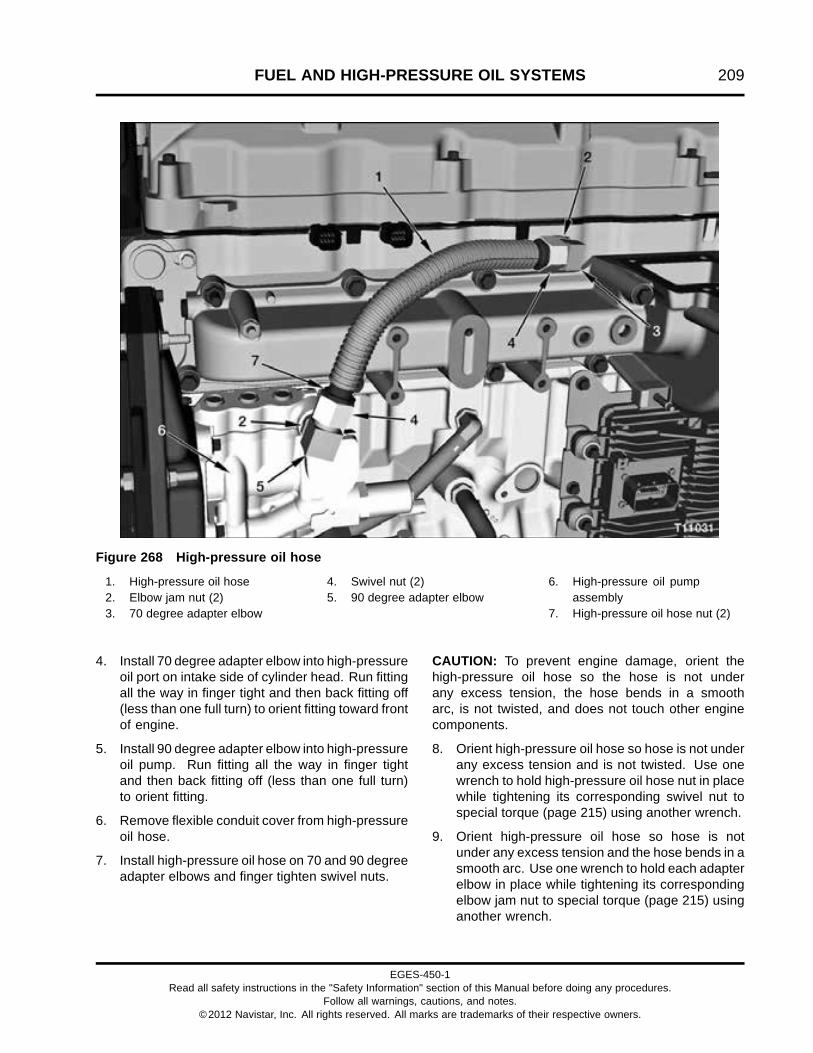
FUEL AND HIGH-PRESSURE OIL SYSTEMS 209
Figure 268 High-pressure oil hose
1. High-pressure oil hose2. Elbow jam nut (2)3. 70 degree adapter elbow
4. Swivel nut (2)5. 90 degree adapter elbow
6. High-pressure oil pumpassembly
7. High-pressure oil hose nut (2)
4. Install 70 degree adapter elbow into high-pressureoil port on intake side of cylinder head. Run fittingall the way in finger tight and then back fitting off(less than one full turn) to orient fitting toward frontof engine.
5. Install 90 degree adapter elbow into high-pressureoil pump. Run fitting all the way in finger tightand then back fitting off (less than one full turn)to orient fitting.
6. Remove flexible conduit cover from high-pressureoil hose.
7. Install high-pressure oil hose on 70 and 90 degreeadapter elbows and finger tighten swivel nuts.
CAUTION: To prevent engine damage, orient thehigh-pressure oil hose so the hose is not underany excess tension, the hose bends in a smootharc, is not twisted, and does not touch other enginecomponents.
8. Orient high-pressure oil hose so hose is not underany excess tension and is not twisted. Use onewrench to hold high-pressure oil hose nut in placewhile tightening its corresponding swivel nut tospecial torque (page 215) using another wrench.
9. Orient high-pressure oil hose so hose is notunder any excess tension and the hose bends in asmooth arc. Use one wrench to hold each adapterelbow in place while tightening its correspondingelbow jam nut to special torque (page 215) usinganother wrench.
EGES-450-1Read all safety instructions in the "Safety Information" section of this Manual before doing any procedures.
Follow all warnings, cautions, and notes.©2012 Navistar, Inc. All rights reserved. All marks are trademarks of their respective owners.

210 FUEL AND HIGH-PRESSURE OIL SYSTEMS
10. Install flexible conduit cover on high-pressure oilhose.
Fuel Filter Assembly
Figure 269 Fuel filter assembly (with heater shown)
1. M8 x 75 bolt2. Dust cap and diagnostic coupling3. M8 x 75 stud bolt (3)4. M6 x 16 bolt (hidden from view)
5. M8 oil filler tube support nut (2)6. Oil filler tube support7. Fuel outlet fitting (return to tank)8. Water drain valve assembly
9. 250 Watt fuel heater (optional)10. Voss® Stop Flow adapter
assembly (from tank)
1. If removed, install a new port cover seal (Figure236) (item 9) on fuel filter assembly. Install portcover and tighten three M6 screws to specialtorque (page 215).
2. Install fuel filter assembly on intake manifold usinga new irregular molded gasket. Tighten three M8x 75 stud bolts and M8 x 75 bolt to special torque(page 215).
3. If removed, install diagnostic coupling and dustcap. Tighten to special torque (page 215).
4. If removed, install Voss® Stop Flow adapterassembly. Tighten to special torque (page 215).
5. Install oil filler tube support, M6 x 16 bolt, and twoM8 oil filler tube support nuts. Tighten M6 x 16bolt and M8 nuts to special torque (page 481).
6. Verify that lever on water drain valve assembly isclosed.
EGES-450-1Read all safety instructions in the "Safety Information" section of this Manual before doing any procedures.
Follow all warnings, cautions, and notes.©2012 Navistar, Inc. All rights reserved. All marks are trademarks of their respective owners.

FUEL AND HIGH-PRESSURE OIL SYSTEMS 211
Water Drain Valve Assembly
Figure 270 Water drain valve assembly and fuelelement assembly (with heater shown)
1. Fuel element assembly (with optional) heater2. O-ring3. Drain stem4. Drain retainer5. M5 screw (2)
1. Install a new water valve O-ring into fuel filterassembly.
2. Install drain stem, drain retainer, and finger tightentwo M5 screws.
3. Using a T27 Torx® bit (page 216), tighten two M5screws to special torque (page 215).
Brushless Electric Fuel Pump Assembly and FuelStrainer
Figure 271 Brushless electric fuel pumpassembly and fuel strainer
1. Pump cover and housing O-ring (2)2. Brushless electric fuel pump assembly3. Fuel filter assembly with heater4. Pump strainer and pump adapter
1. Lubricate two new pump cover and housingO-rings with clean diesel fuel and install on fuelpump and outside of pump adapter.
2. Lubricate new fuel pump O-ring (Figure 236) (item5) with clean diesel fuel and install on inside ofpump strainer and pump adapter.
3. Install pump strainer and pump adapter onbrushless electric fuel pump assembly.
4. Install brushless electric fuel pump assembly andfuel strainer into fuel filter assembly.
5. Install three M5 x 25 pump cover screws andtighten to special torque (page 215). Do not overtighten pump cover screws.
EGES-450-1Read all safety instructions in the "Safety Information" section of this Manual before doing any procedures.
Follow all warnings, cautions, and notes.©2012 Navistar, Inc. All rights reserved. All marks are trademarks of their respective owners.

212 FUEL AND HIGH-PRESSURE OIL SYSTEMS
Fuel Pressure Regulator Valve Assembly
Figure 272 Fuel pressure regulator valveassembly and cover plate
1. Fuel filter assembly (with or without heater)2. Fuel pressure regulator valve assembly3. Fuel pressure regulator valve spring4. Cover plate seal5. Bottom cover plate6. M6 screw (5)7. Fuel delivery pressure (FDP) sensor
1. Install new cover plate seal into groove of bottomcover plate.
2. Lubricate new fuel pressure regulator valveassembly with clean diesel fuel and install onvalve spring.
3. Place fuel pressure regulator valve spring and fuelpressure regulator valve assembly onto bottomcover plate.
4. Lift bottom cover plate assembly up to fuelfilter assembly. Ensure fuel pressure regulatorvalve assembly installs smoothly into fuel filterassembly.
NOTE: If fuel pressure regulator valve assembly bindsduring installation, remove valve spring and regulatorvalve assembly. Check spring for binding, and checkfuel pressure regulator valve assembly for damage.Correct the problem, lubricate fuel pressure regulatorvalve assembly with clean diesel fuel, and install coverplate assembly.
5. Using a T30 Torx® bit (page 216), install fiveM6 screws using a star pattern and tighten eachscrew one full turn at a time until all bolts aresnug. Ensure bottom cover plate is flush withbottom surface of fuel filter assembly.
6. Tighten five M6 screws to 9.6 N·m (85 lbf·in).
Water In Fuel (WIF) Sensor, Fuel DeliveryPressure (FDP) Sensor, and 250 Watt Fuel Heater
Figure 273 Fuel filter assembly with heater (ifequipped)
1. Water in fuel (WIF) sensor2. Fuel delivery pressure (FDP) sensor3. 250 Watt fuel heater (optional)
NOTE: If not equipped with 250 watt fuel heater, skipsteps 1 through 3.
EGES-450-1Read all safety instructions in the "Safety Information" section of this Manual before doing any procedures.
Follow all warnings, cautions, and notes.©2012 Navistar, Inc. All rights reserved. All marks are trademarks of their respective owners.

FUEL AND HIGH-PRESSURE OIL SYSTEMS 213
1. Lubricate a new O-ring with clean diesel fuel andinstall O-ring on to 250 watt fuel heater.
2. Install 250 watt fuel heater into fuel filter assemblyand finger tighten two M6 x 25 bolts.
3. Tighten two M6 x 25 250 watt fuel heater bolts tospecial torque (page 215).
4. Lubricate a new O-ring with clean diesel fuel andinstall on to the WIF sensor.
5. Install WIF sensor into fuel filter assembly withheater and tighten to 2 N·m (15 lbf·in) or until
O-ring contacts fuel filter assembly with heaterand then turn sensor an additional 1/16 of a turn.
6. Lubricate a new O-ring with clean diesel fuel andinstall O-ring on FDP sensor.
7. Install FDP sensor into bottom of fuel filterassembly and tighten to special torque (page215).
EGES-450-1Read all safety instructions in the "Safety Information" section of this Manual before doing any procedures.
Follow all warnings, cautions, and notes.©2012 Navistar, Inc. All rights reserved. All marks are trademarks of their respective owners.
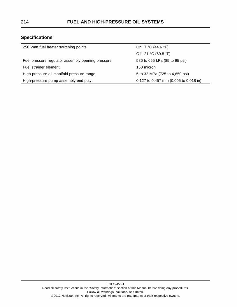
214 FUEL AND HIGH-PRESSURE OIL SYSTEMS
Specifications
On: 7 °C (44.6 °F)250 Watt fuel heater switching points
Off: 21 °C (69.8 °F)
Fuel pressure regulator assembly opening pressure 586 to 655 kPa (85 to 95 psi)
Fuel strainer element 150 micron
High-pressure oil manifold pressure range 5 to 32 MPa (725 to 4,650 psi)
High-pressure pump assembly end play 0.127 to 0.457 mm (0.005 to 0.018 in)
EGES-450-1Read all safety instructions in the "Safety Information" section of this Manual before doing any procedures.
Follow all warnings, cautions, and notes.©2012 Navistar, Inc. All rights reserved. All marks are trademarks of their respective owners.

FUEL AND HIGH-PRESSURE OIL SYSTEMS 215
Special Torque
Adapter elbow jam nut, 70 and 90 degree 105 N·m (78 lbf·ft)
Brushless electric fuel pump assembly, M5 x 25 screw 5 N·m (44 lbf·in)
Diagnostic coupling assembly 17 N·m (145 lbf·in)
Fuel Delivery Pressure (FDP) sensor 11 N·m (100 lbf·in)
Fuel filter cap 40 N·m (29 lbf·ft)
Fuel filter assembly housing bolt and stud bolts, M8 x 75 27 N·m (20 lbf·ft)
250 Watt fuel heater bolts, M6 x 25 10 N·m (85 lbf·in)
Fuel filter inlet fitting 18 N·m (155 lbf·in)
Fuel pressure regulator valve cover plate M6 screw See Fuel Pressure Regulator ValveAssembly (page 212) for tighteningprocedure
High-pressure oil hose (swivel nuts) 65 N·m (48 lbf·ft)
High-pressure oil manifold bolts, M8 x 90 See High-pressure Oil Manifold (page206) for correct torque and sequence.
High-pressure oil pump assembly bolts, M8 x 30 and M8 x 100 30 N·m (22 lbf·ft)
High-pressure oil pump gear bolt, M14 x 1.5 left 244 N·m (179 lbf·ft)
Injector hold down clamp bolt 41 N·m (30 lbf·ft)
Injector oil inlet adapter assembly 204 N·m (150 lbf·ft)
IPR valve 50 N·m (37 lbf·ft)
M12 fuel rail plug 25 N·m (18 lbf·ft)
Oil rail plug assembly (bottom) 204 N·m (150 lbf·ft)
Plug assembly, M10 and M12 12 N·m (108 lbf·in)
Port cover M6 screws 10 N·m (85 lbf·in)
Pump cover screws, M5 x 25 5 N·m (45 lbf·in)
Rail end plug assembly 204 N·m (150 lbf·ft)
Voss® Stop Flow adapter assembly 27 N·m (20 lbf·ft)
Water drain valve assembly M5 screws 6 N·m (50 lbf·in)
Water In Fuel (WIF) sensor See Water In Fuel (WIF) Sensor, FuelDelivery Pressure (FDP) Sensor, and 250Watt Fuel Heater (page 213) for tighteningprocedure.
EGES-450-1Read all safety instructions in the "Safety Information" section of this Manual before doing any procedures.
Follow all warnings, cautions, and notes.©2012 Navistar, Inc. All rights reserved. All marks are trademarks of their respective owners.

216 FUEL AND HIGH-PRESSURE OIL SYSTEMS
Special Service Tools
Injector Oil Inlet Plugs ZTSE4660
Fuel Injector Remover Tool (T40) ZTSE4524
High Pressure Rail Adapter Socket ZTSE4725
IPR Socket ZTSE4931
Suction bulb Obtain locally
T27 Torx® bit Obtain locally
T30 Torx® bit Obtain locally
EGES-450-1Read all safety instructions in the "Safety Information" section of this Manual before doing any procedures.
Follow all warnings, cautions, and notes.©2012 Navistar, Inc. All rights reserved. All marks are trademarks of their respective owners.

ENGINE BRAKE 217
Table of Contents
Exploded View and Description. . . . . . . . . . . . . . . . . . . . . . . . . . . . . . . . . . . . . . . . . . . . . . . . . . . . . . . . . . . . . . . . . . . . . . . . . . . . . . . . . . . . .219High-pressure Oil Manifold (Brake). . . . . . . . . . . . . . . . . . . . . . . . . . . . . . . . . . . . . . . . . . . . . . . . . . . . . . . . . . . . . . . . . . . . . . .219
Periodic Service. . . . . . . . . . . . . . . . . . . . . . . . . . . . . . . . . . . . . . . . . . . . . . . . . . . . . . . . . . . . . . . . . . . . . . . . . . . . . . . . . . . . . . . . . . . . . . . . . . . . . . . .220Engine Brake Lash Adjustment. . . . . . . . . . . . . . . . . . . . . . . . . . . . . . . . . . . . . . . . . . . . . . . . . . . . . . . . . . . . . . . . . . . . . . . . . . . .220
Removal. . . . . . . . . . . . . . . . . . . . . . . . . . . . . . . . . . . . . . . . . . . . . . . . . . . . . . . . . . . . . . . . . . . . . . . . . . . . . . . . . . . . . . . . . . . . . . . . . . . . . . . . . . . . . . . . .223Engine Compression Brake (ECB) Valve. . . . . . . . . . . . . . . . . . . . . . . . . . . . . . . . . . . . . . . . . . . . . . . . . . . . . . . . . . . . . . . . .223Engine Compression Brake Pressure (ECBP) Sensor. . . . . . . . . . . . . . . . . . . . . . . . . . . . . . . . . . . . . . . . . . . . . . . . .223Valve Cover Gasket (Harness) Assembly (Brake). . . . . . . . . . . . . . . . . . . . . . . . . . . . . . . . . . . . . . . . . . . . . . . . . . . . . .224High-pressure Oil Manifold (Brake). . . . . . . . . . . . . . . . . . . . . . . . . . . . . . . . . . . . . . . . . . . . . . . . . . . . . . . . . . . . . . . . . . . . . . .225Oil Pressure Relief Valve. . . . . . . . . . . . . . . . . . . . . . . . . . . . . . . . . . . . . . . . . . . . . . . . . . . . . . . . . . . . . . . . . . . . . . . . . . . . . . . . . . . .226Brake Actuator Piston Assembly. . . . . . . . . . . . . . . . . . . . . . . . . . . . . . . . . . . . . . . . . . . . . . . . . . . . . . . . . . . . . . . . . . . . . . . . . .226
Cleaning and Inspection. . . . . . . . . . . . . . . . . . . . . . . . . . . . . . . . . . . . . . . . . . . . . . . . . . . . . . . . . . . . . . . . . . . . . . . . . . . . . . . . . . . . . . . . . . . . . .228
Installation. . . . . . . . . . . . . . . . . . . . . . . . . . . . . . . . . . . . . . . . . . . . . . . . . . . . . . . . . . . . . . . . . . . . . . . . . . . . . . . . . . . . . . . . . . . . . . . . . . . . . . . . . . . . . .229Brake Actuator Piston Assembly. . . . . . . . . . . . . . . . . . . . . . . . . . . . . . . . . . . . . . . . . . . . . . . . . . . . . . . . . . . . . . . . . . . . . . . . . .229Oil Pressure Relief Valve. . . . . . . . . . . . . . . . . . . . . . . . . . . . . . . . . . . . . . . . . . . . . . . . . . . . . . . . . . . . . . . . . . . . . . . . . . . . . . . . . . . .229High-pressure Oil Manifold (Brake). . . . . . . . . . . . . . . . . . . . . . . . . . . . . . . . . . . . . . . . . . . . . . . . . . . . . . . . . . . . . . . . . . . . . . .230Valve Cover Gasket (Harness) Assembly (Brake). . . . . . . . . . . . . . . . . . . . . . . . . . . . . . . . . . . . . . . . . . . . . . . . . . . . . .232Engine Compression Brake Pressure (ECBP) Sensor. . . . . . . . . . . . . . . . . . . . . . . . . . . . . . . . . . . . . . . . . . . . . . . . .232Engine Compression Brake (ECB) valve assembly. . . . . . . . . . . . . . . . . . . . . . . . . . . . . . . . . . . . . . . . . . . . . . . . . . . .233
Specifications. . . . . . . . . . . . . . . . . . . . . . . . . . . . . . . . . . . . . . . . . . . . . . . . . . . . . . . . . . . . . . . . . . . . . . . . . . . . . . . . . . . . . . . . . . . . . . . . . . . . . . . . . .234
Special Torque.. . . . . . . . . . . . . . . . . . . . . . . . . . . . . . . . . . . . . . . . . . . . . . . . . . . . . . . . . . . . . . . . . . . . . . . . . . . . . . . . . . . . . . . . . . . . . . . . . . . . . . . . .234
Special Service Tools. . . . . . . . . . . . . . . . . . . . . . . . . . . . . . . . . . . . . . . . . . . . . . . . . . . . . . . . . . . . . . . . . . . . . . . . . . . . . . . . . . . . . . . . . . . . . . . . .234
EGES-450-1Read all safety instructions in the "Safety Information" section of this Manual before doing any procedures.
Follow all warnings, cautions, and notes.©2012 Navistar, Inc. All rights reserved. All marks are trademarks of their respective owners.
218 ENGINE BRAKE
EGES-450-1Read all safety instructions in the "Safety Information" section of this Manual before doing any procedures.
Follow all warnings, cautions, and notes.©2012 Navistar, Inc. All rights reserved. All marks are trademarks of their respective owners.

ENGINE BRAKE 219
Exploded View and DescriptionHigh-pressure Oil Manifold (Brake)
Figure 274 High-pressure oil manifold (brake)
1. Engine Compression BrakePressure (ECBP) sensor
2. Engine Compression Brake(ECB) valve assembly
3. M10 plug (2 top, 1 bottom notshown), (3)
4. Injection Control Pressure (ICP)sensor
5. M8 x 90 bolt (12)6. M12 plug7. Rail end plug assembly (2)8. Injector oil inlet adaptor (6)9. Back-up ring (6)10. Injector oil inlet seal (6)11. High-pressure oil manifold
(brake)
12. Oil inlet O-ring13. Brake actuator piston (6)14. Oil pressure relief valve15. Brake actuator piston lock nut
(6)
The engine brake system uses high-pressure oil inthe high-pressure oil manifold, controlled by a Engine
Compression Brake (ECB) valve, to force six brakeactuator pistons down onto the valve bridges. This
EGES-450-1Read all safety instructions in the "Safety Information" section of this Manual before doing any procedures.
Follow all warnings, cautions, and notes.©2012 Navistar, Inc. All rights reserved. All marks are trademarks of their respective owners.

220 ENGINE BRAKE
partially opens one exhaust valve for each cylinderresulting in the release of compression pressure onthe power stroke, which increases engine braking.See Engine Brake (page 54) for additional details.
Periodic Service
GOVERNMENT REGULATION: Enginefluids (oil, fuel, and coolant) may be a hazardto human health and the environment.Handle all fluids and other contaminatedmaterials (e.g. filters, rags) in accordancewith applicable regulations. Recycleor dispose of engine fluids, filters, andother contaminated materials according toapplicable regulations.
WARNING: To prevent personal injury ordeath, read all safety instructions in the "SafetyInformation" section of this manual.
WARNING: To prevent personal injury ordeath, shift transmission to park or neutral, setparking brake, and block wheels before doingdiagnostic or service procedures.
WARNING: To prevent personal injury ordeath, wear safety glasses with side shields.Limit compressed air pressure to 207 kPa (30 psi).
WARNING: To prevent personal injury ordeath, disconnect the main battery negativeterminal before disconnecting or connectingelectrical components.
WARNING: To prevent personal injury ordeath, do not let engine fluids stay on your skin.Clean skin and nails using hand cleaner and washwith soap and water. Wash or discard clothingand rags contaminated with engine fluids.
NOTE: If the valve cover is removed for any reason,verify six brake piston locknuts are tight. If loose,verify and reset brake lash.
Engine Brake Lash Adjustment
Crankshaft is rotated twice during brake lashadjustment procedure.
• Three brake actuator pistons are adjustedwhen piston 1 is at Top Dead Center (TDC)compression.
• Three brake actuator pistons are adjustedwhen piston 6 is at Top Dead Center (TDC)compression.
Corresponding intake and exhaust valve lash can beadjusted (page 333) when piston 1 and 6 are at TDCcompression.
NOTE: Valve lash adjustments are not required whenadjusting engine brake lash.
1. On engines rated at 245 horsepower and above,remove the interstage cooler and piping. SeeInterstage Cooler (ISC) (page 132).
2. Remove valve cover. See Valve Cover (page336).
3. Turn the crankshaft in the direction of enginerotation to remove gear lash. Position piston 1 atTDC compression by observing cylinder 6 rockerarms in overlap as the vibration damper timingmark approaches the TDC mark on the frontcover. Cylinder 6 exhaust valve will be closing(coming up) and the intake valve will be startingto open (going down).
4. If piston 1 is at TDC compression, see Chart 1(page 221) and do steps 4 and 5 for cylinders 1,3, and 5.
EGES-450-1Read all safety instructions in the "Safety Information" section of this Manual before doing any procedures.
Follow all warnings, cautions, and notes.©2012 Navistar, Inc. All rights reserved. All marks are trademarks of their respective owners.

ENGINE BRAKE 221
Chart 1
Brake and valve lash adjustments (inches) with piston 1 at TDC compression (Chart 1)
Cylinder 1 Cylinder 2 Cylinder 3 Cylinder 4 Cylinder 5 Cylinder 6
intake
1
exhaust
2
intake
3
exhaust
4
intake
5
exhaust
6
intake
7
exhaust
8
intake
9
exhaust
10
intake
11
exhaust
12
0.019 0.019 0.019 0.019 0.019 0.019
Brake 0.019 Brake 0.019 Brake 0.019
Brake and valve lash adjustments with piston 1 at TDC compression
Chart 2
Brake and valve lash adjustments (inches) with piston 6 at TDC compression (Chart 2)
Cylinder 1 Cylinder 2 Cylinder 3 Cylinder 4 Cylinder 5 Cylinder 6
intake
1
exhaust
2
intake
3
exhaust
4
intake
5
exhaust
6
intake
7
exhaust
8
intake
9
exhaust
10
intake
11
exhaust
12
0.019 0.019 0.019 0.019 0.019 0.019
Brake 0.019 Brake 0.019 Brake 0.019
Brake and valve lash adjustments with piston 6 at TDC compression
Figure 275 High-pressure oil manifold (brake)
1. Cylinder 12. Cylinder 23. Cylinder 3
4. Cylinder 45. Cylinder 56. Cylinder 6
7. Brake actuator piston locknut (6)8. Front of engine
EGES-450-1Read all safety instructions in the "Safety Information" section of this Manual before doing any procedures.
Follow all warnings, cautions, and notes.©2012 Navistar, Inc. All rights reserved. All marks are trademarks of their respective owners.

222 ENGINE BRAKE
Figure 276 Brake lash measurement (typical)
1. Brake actuator piston screw2. Brake actuator piston locknut
3. Valve bridge4. Feeler gauge
5. Measure brake lash when engine is cold.Put a 0.48 mm (0.019 in) feeler gauge (page234) between the brake actuator piston and valvebridge, a light drag on the feeler gauge shouldbe felt. If adjustment is required, loosen actuatorpiston locknut and turn actuator piston screw.
6. Once brake lash is set, tighten actuator pistonlocknut to special torque (page 234) and removefeeler gauge. Recheck lash with a light drag onfeeler gauge. If drag is too tight or loose, repeatsteps 4 and 5.
Corresponding valve lash can be adjusted beforerotating crankshaft for either the intake or exhaustfor cylinders 1, 2, and 3 but not both at the sametime. See Chart 1 (page 221).
7. Turn the crankshaft 360° in the direction of enginerotation to remove gear lash. Position piston 6 atTDC compression by observing cylinder 1 rockerarms in overlap as the vibration damper timingmark approaches the TDC mark on the frontcover.
8. If piston 6 is at TDC compression, see Chart 2(page 221) and do steps 4 and 5 for cylinders 2,4, and 6.
Corresponding valve lash can be adjusted foreither the intake or exhaust for cylinders 2, 4, and6 but not both at the same time. See Chart 2(page 221).
EGES-450-1Read all safety instructions in the "Safety Information" section of this Manual before doing any procedures.
Follow all warnings, cautions, and notes.©2012 Navistar, Inc. All rights reserved. All marks are trademarks of their respective owners.

ENGINE BRAKE 223
RemovalInspect for external damage or oil leaks from sensorsor valve. Only remove sensor if damage, diagnosticcode, or test indicated a problem.
NOTE: If the valve cover is removed for any reason,verify six brake piston locknuts are tight. If loose,verify and reset engine brake lash (page 220).
Engine Compression Brake (ECB) Valve
1. Remove valve cover. See Valve Cover (page336).
Figure 277 ECB valve assembly (typical)
1. Solenoid2. Nut3. Harness connector
2. Disconnect harness connector from ECB valveassembly.
3. Use a 12 point (1-1/16 inch) socket to removenut and solenoid from Engine Compression Brake(ECB) valve.
Figure 278 ECB valve
4. Remove ECB valve from high-pressure oilmanifold.
5. Remove and discard ECB valve O-rings andback-up rings.
Engine Compression Brake Pressure (ECBP)Sensor
Figure 279 ECBP sensor (typical)
1. Disconnect 3-pin harness connector from ECBPsensor installed in the high-pressure oil manifoldforward of cylinder 2 fuel injector.
2. Remove ECBP sensor.
3. Discard sensor O-ring.
EGES-450-1Read all safety instructions in the "Safety Information" section of this Manual before doing any procedures.
Follow all warnings, cautions, and notes.©2012 Navistar, Inc. All rights reserved. All marks are trademarks of their respective owners.

224 ENGINE BRAKE
Valve Cover Gasket (Harness) Assembly (Brake)
Figure 280 Valve cover gasket (harness) assembly (brake, typical)
1. Injector 1 connector (front ofengine)
2. Injector 2 connector3. Injector 3 connector4. Injector 4 connector5. Injector 5 connector
6. Injector 6 connector7. Injection Control Pressure (ICP)
sensor connector8. Engine Compression Brake
(ECB) valve
9. Engine Compression BrakePressure (ECBP) sensorconnector
1. Disconnect four injector wiring harnessconnectors from the valve cover gasket harnessassembly located under the valve cover.
NOTE: ICP and ECBP sensors are identical and sharethe same part number.
2. Disconnect six injector connectors, ICP, andECBP sensor connectors.
3. Disconnect ECB valve connector.
4. Starting at one side, lightly pry up and open eachof the six wire channel retainers while gentlypulling up to remove valve cover gasket harnessfrom engine.
EGES-450-1Read all safety instructions in the "Safety Information" section of this Manual before doing any procedures.
Follow all warnings, cautions, and notes.©2012 Navistar, Inc. All rights reserved. All marks are trademarks of their respective owners.

ENGINE BRAKE 225
High-pressure Oil Manifold (Brake)
1. Remove 12 M8 x 90 bolts holding high-pressureoil manifold to the cylinder head. Do not discard,save for installation.
Figure 281 High-pressure oil manifold removal(typical)
WARNING: To prevent personal injury ordeath, get assistance to remove or install thehigh-pressure oil manifold assembly.
2. Lift high-pressure oil manifold straight up justenough to drain oil out of manifold before lifting itaway from cylinder head.
3. Lift up and remove high-pressure oil manifold fromengine.
Figure 282 Injector oil inlet adaptor installed inhigh-pressure oil manifold
1. Injector oil inlet adaptor2. Backup ring3. Injector oil inlet seal4. Oil inlet tube5. Internal O-ring (not serviceable)
4. Remove and discard injector oil inlet adaptorseals and backup rings.
5. Remove any damaged injector oil inlet adaptorassemblies using High Pressure Rail AdapterSocket (page 234).
Figure 283 Oil inlet O-ring (typical)
6. Discard oil inlet O-ring
EGES-450-1Read all safety instructions in the "Safety Information" section of this Manual before doing any procedures.
Follow all warnings, cautions, and notes.©2012 Navistar, Inc. All rights reserved. All marks are trademarks of their respective owners.

226 ENGINE BRAKE
Oil Pressure Relief Valve
Figure 284 Oil pressure relief valve
1. Remove oil pressure relief valve fromhigh-pressure oil manifold.
2. Discard valve O-ring.
Brake Actuator Piston Assembly
NOTE: Do steps 1 through 3 as required for the sixbrake actuator piston assemblies.
Figure 285 Brake actuator piston locknut
1. Remove brake actuator piston locknut. Do notdiscard, save for installation.
Figure 286 Brake actuator piston removal
2. Unscrew the brake actuator piston assembly fromthe high-pressure oil manifold.
EGES-450-1Read all safety instructions in the "Safety Information" section of this Manual before doing any procedures.
Follow all warnings, cautions, and notes.©2012 Navistar, Inc. All rights reserved. All marks are trademarks of their respective owners.

ENGINE BRAKE 227
Figure 287 Brake actuator piston assembly
CAUTION: To prevent engine damage, usepermanent marker to identify internal enginecomponents and their orientation. Do not use paintor temporary markers.
3. Remove and mark brake actuator piston forinstallation in original location.
NOTE: There are no seals associated with the brakeactuator piston assembly.
EGES-450-1Read all safety instructions in the "Safety Information" section of this Manual before doing any procedures.
Follow all warnings, cautions, and notes.©2012 Navistar, Inc. All rights reserved. All marks are trademarks of their respective owners.

228 ENGINE BRAKE
Cleaning and Inspection1. Clean external surface of high-pressure oil
manifold, brake actuator pistons, valve bridges,oil pressure relief valve, Engine CompressionBrake (ECB) valve, and Engine CompressionBrake Pressure (ECBP) sensor with a suitablenon-caustic solvent.
2. Clean any oil and debris from the 12high-pressure oil manifold mounting bolthole threads. Clean bolt hole threads will ensurethe proper torque is reached when tightening themounting bolts.
WARNING: To prevent personal injury ordeath, wear safety glasses. Limit compressed airpressure to 207 kPa (30 psi).
3. Blow parts dry using filtered compressed air.
4. Inspect high-pressure oil manifold, and oilpressure relief valve for cracks and leaks.Replace cracked or leaking parts.
Figure 288 Injector oil inlet adaptor installed inhigh-pressure oil manifold
1. Injector oil inlet adaptor2. Backup ring3. Injector oil inlet seal4. Oil inlet tube5. Internal O-ring (not serviceable)
5. Verify six injector oil inlet adaptor oil inlet tubesmove and are not frozen. Inspect injector oilinlet adaptors for internal O-ring extrusion andhigh-pressure oil leak paths. Replace any adaptor
which has an extruded internal O-ring, frozen oilinlet tube, or high-pressure oil leak path.
Replace old backup ring and injector oil inlet sealwith new.
6. Inspect all brake actuator pistons and valvebridge contact surfaces. Look for pitting andmaterial transfer deformation. Replace pitted ordeformed parts if necessary. Polished surfacesare acceptable.
7. Inspect the ECB valve and ECBP sensor forcracks. Replace cracked parts.
EGES-450-1Read all safety instructions in the "Safety Information" section of this Manual before doing any procedures.
Follow all warnings, cautions, and notes.©2012 Navistar, Inc. All rights reserved. All marks are trademarks of their respective owners.

ENGINE BRAKE 229
InstallationBrake Actuator Piston Assembly
NOTE: Be sure the old backup ring and injector oilinlet seal on the high-pressure oil manifold has beenreplaced with a new seal and ring.
NOTE: Do steps 1 through 4 for each brake actuatorpiston assembly removed.
Figure 289 Brake actuator piston assembly
1. Lubricate brake actuator piston and high-pressureoil manifold bore with clean engine oil.
2. Install brake actuator piston into high-pressure oilmanifold. Install used brake actuator pistons inthe same location as removed.
NOTE: There are no seals associated with the brakeactuator piston assembly. It is normal for some oil toexit past the piston assemblies.
Figure 290 Brake actuator piston installation
3. Screw brake actuator piston assembly intohigh-pressure oil manifold until bottomed out.
Figure 291 Brake actuator piston locknut
4. Install brake actuator piston locknut. Do nottighten at this time.
NOTE: Final brake lash adjustments will be madeafter high-pressure oil manifold is installed on thecylinder head.
Oil Pressure Relief Valve
Figure 292 Oil pressure relief valve
1. Install new O-ring on oil pressure relief valve.
2. Install oil pressure relief valve and tighten tospecial torque (page 234).
EGES-450-1Read all safety instructions in the "Safety Information" section of this Manual before doing any procedures.
Follow all warnings, cautions, and notes.©2012 Navistar, Inc. All rights reserved. All marks are trademarks of their respective owners.

230 ENGINE BRAKE
High-pressure Oil Manifold (Brake)
1. Back off all brake actuator piston lashadjustments, for correct high-pressure oilmanifold bolt torque during high-pressure oilmanifold installation.
Figure 293 Injector oil inlet adaptor installed inhigh-pressure oil manifold
1. Injector oil inlet adaptor2. Backup ring3. Injector oil inlet seal4. Oil inlet tube5. Internal O-ring (not serviceable)
2. Install injector oil inlet adaptors with HighPressure Rail Adapter Socket (page 234).Tighten injector oil inlet adaptors to specialtorque (page 234).
3. Install new backup rings and injector oil inlet sealson all oil inlet adaptors that were not replaced.
4. Coat backup rings and injector oil inlet seals withclean engine oil.
Figure 294 Oil inlet O-ring (typical)
5. Coat new oil inlet O-ring with clean engine oil andinstall in cylinder head recess.
6. If valve bridges have been removed install at thistime. Also check valve lash adjustment beforeinstalling the high-pressure oil manifold. SeeValve Lash Adjustment (page 333) for adjustmentprocedure.
Figure 295 High-pressure oil manifoldinstallation (typical)
WARNING: To prevent personal injury ordeath, get assistance to remove and install thehigh-pressure oil manifold assembly.
7. With help from an assistant, lift the high-pressureoil manifold up and carefully place on engine.
CAUTION: To prevent engine damage, carefully alignsix injector oil inlet ports with six injector oil inletadaptors of the high-pressure oil manifold beforetightening oil manifold bolts.
8. Carefully align six injector oil inlet ports with sixinjector oil inlet adapters of the high-pressure oilmanifold and firmly push down to “snap” manifoldin place.
9. Once the high-pressure oil manifold is set in placeonto the cylinder head; shine a flashlight at all thepoints where the high-pressure oil manifold restson the cylinder head.
• If all points of the high-pressure oil manifoldare resting on the cylinder head, thehigh-pressure oil manifold is seated correctly,go to step 10.
EGES-450-1Read all safety instructions in the "Safety Information" section of this Manual before doing any procedures.
Follow all warnings, cautions, and notes.©2012 Navistar, Inc. All rights reserved. All marks are trademarks of their respective owners.

ENGINE BRAKE 231
• If all the points of the high-pressure oilmanifold are not resting on the cylinderhead; push down on the high points to “snap”manifold in place. Once again, check allpoints with the flashlight, if high-pressure oilmanifold is seated correctly, go to step 10.
10. Install and finger tighten 12 M8 x 90 bolts securinghigh-pressure oil manifold to the cylinder head.
Figure 296 High-pressure oil manifold bolttorque sequence
11. Tighten 12 high-pressure oil manifold M8 x 90bolts in the proper torque sequence to 30 N·m (22lbf·ft).
12. Adjust engine brake lash (page 220) for allcylinders.
NOTE: Air trapped in the high-pressure oil manifoldwill be purged automatically during cranking and startup.
EGES-450-1Read all safety instructions in the "Safety Information" section of this Manual before doing any procedures.
Follow all warnings, cautions, and notes.©2012 Navistar, Inc. All rights reserved. All marks are trademarks of their respective owners.

232 ENGINE BRAKE
Valve Cover Gasket (Harness) Assembly (Brake)
Figure 297 Valve cover gasket (harness) assembly (brake, typical)
1. Injector 1 connector (front ofengine)
2. Injector 2 connector3. Injector 3 connector4. Injector 4 connector5. Injector 5 connector
6. Injector 6 connector7. Injection Control Pressure (ICP)
sensor connector8. Engine Compression Brake
(ECB) valve connector
9. Engine Compression BrakePressure (ECBP) sensorconnector
NOTE: ICP and ECBP sensors are identical and sharethe same part number.
1. Position valve cover gasket harness on cylinderhead and carefully push down each of the sixwire channel retainers to snap harness ontohigh-pressure oil manifold.
2. Connect six injectors, ICP sensor, ECBP sensor,and ECB valve harness connectors.
Engine Compression Brake Pressure (ECBP)Sensor
Figure 298 ECBP sensor (typical)
1. Install new O-ring on ECBP sensor and lubricatewith clean engine oil.
2. Install ECBP sensor into high-pressure oilmanifold, forward of cylinder 2 fuel injector,and tighten to special torque (page 234).
3. Connect valve cover gasket harness connector toECBP sensor.
EGES-450-1Read all safety instructions in the "Safety Information" section of this Manual before doing any procedures.
Follow all warnings, cautions, and notes.©2012 Navistar, Inc. All rights reserved. All marks are trademarks of their respective owners.

ENGINE BRAKE 233
Engine Compression Brake (ECB) valve assembly
Figure 299 Engine Compression Brake (ECB)valve seals
1. O-ring2. Back-up ring (2)3. O-ring
1. Install new O-rings and back-up rings on EngineCompression Brake (ECB) valve.
2. Lubricate O-rings with clean engine oil.
Figure 300 Engine Compression Brake (ECB)valve (typical)
3. Install Engine Compression Brake (ECB) valve inhigh-pressure oil manifold.
4. Tighten Engine Compression Brake (ECB) valveto special torque (page 234).
Figure 301 ECB valve assembly
1. Solenoid2. Solenoid nut3. Harness connector
5. Install solenoid over the Engine CompressionBrake (ECB) valve.
CAUTION: To prevent engine damage, ECB valveharness connector must be positioned to give properclearance for rocker arm movement.
6. Install solenoid nut and position ECB valveharness connector to give proper clearance forrocker arm movement.
7. Using a 12 point (1–1/16 in) socket (page 234),tighten solenoid nut to special torque (page 234).
8. Connect valve cover gasket harness connector toECB valve assembly.
EGES-450-1Read all safety instructions in the "Safety Information" section of this Manual before doing any procedures.
Follow all warnings, cautions, and notes.©2012 Navistar, Inc. All rights reserved. All marks are trademarks of their respective owners.
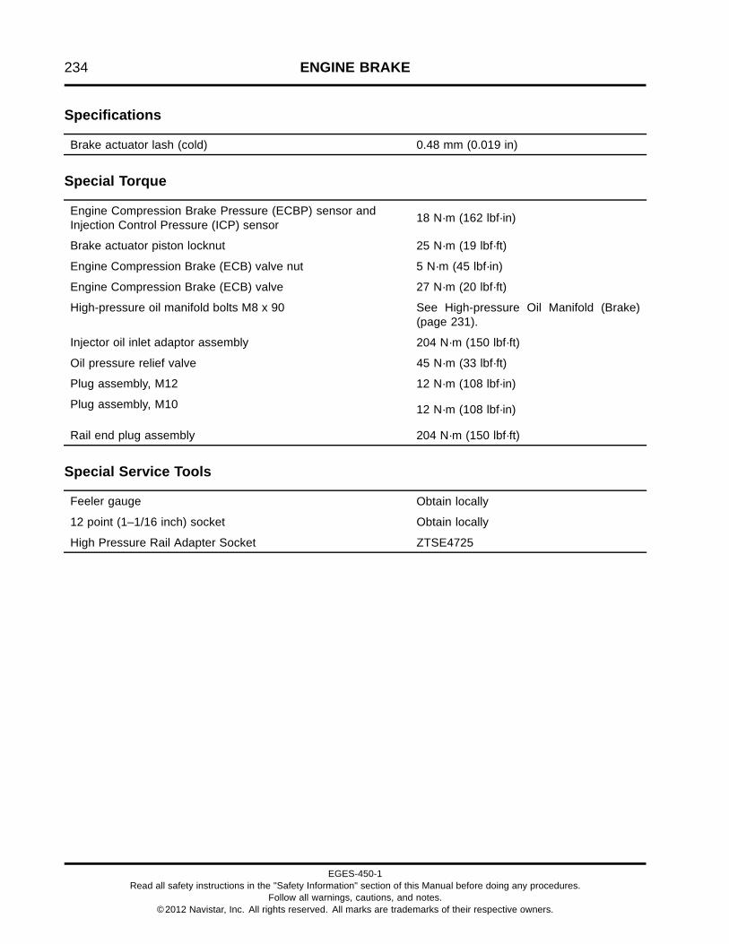
234 ENGINE BRAKE
Specifications
Brake actuator lash (cold) 0.48 mm (0.019 in)
Special Torque
Engine Compression Brake Pressure (ECBP) sensor andInjection Control Pressure (ICP) sensor 18 N·m (162 lbf·in)
Brake actuator piston locknut 25 N·m (19 lbf·ft)
Engine Compression Brake (ECB) valve nut 5 N·m (45 lbf·in)
Engine Compression Brake (ECB) valve 27 N·m (20 lbf·ft)
High-pressure oil manifold bolts M8 x 90 See High-pressure Oil Manifold (Brake)(page 231).
Injector oil inlet adaptor assembly 204 N·m (150 lbf·ft)
Oil pressure relief valve 45 N·m (33 lbf·ft)
Plug assembly, M12 12 N·m (108 lbf·in)
Plug assembly, M10 12 N·m (108 lbf·in)
Rail end plug assembly 204 N·m (150 lbf·ft)
Special Service Tools
Feeler gauge Obtain locally
12 point (1–1/16 inch) socket Obtain locally
High Pressure Rail Adapter Socket ZTSE4725
EGES-450-1Read all safety instructions in the "Safety Information" section of this Manual before doing any procedures.
Follow all warnings, cautions, and notes.©2012 Navistar, Inc. All rights reserved. All marks are trademarks of their respective owners.

AIR COMPRESSOR AND POWER STEERING PUMP 235
Table of Contents
Illustrations. . . . . . . . . . . . . . . . . . . . . . . . . . . . . . . . . . . . . . . . . . . . . . . . . . . . . . . . . . . . . . . . . . . . . . . . . . . . . . . . . . . . . . . . . . . . . . . . . . . . . . . . . . . . .237Air Compressor. . . . . . . . . . . . . . . . . . . . . . . . . . . . . . . . . . . . . . . . . . . . . . . . . . . . . . . . . . . . . . . . . . . . . . . . . . . . . . . . . . . . . . . . . . . . . . .237Power Steering Pump.. . . . . . . . . . . . . . . . . . . . . . . . . . . . . . . . . . . . . . . . . . . . . . . . . . . . . . . . . . . . . . . . . . . . . . . . . . . . . . . . . . . . . . 238
Description. . . . . . . . . . . . . . . . . . . . . . . . . . . . . . . . . . . . . . . . . . . . . . . . . . . . . . . . . . . . . . . . . . . . . . . . . . . . . . . . . . . . . . . . . . . . . . . . . . . . . . . . . . . . . .239Air Compressor. . . . . . . . . . . . . . . . . . . . . . . . . . . . . . . . . . . . . . . . . . . . . . . . . . . . . . . . . . . . . . . . . . . . . . . . . . . . . . . . . . . . . . . . . . . . . . .239Power Steering Pump.. . . . . . . . . . . . . . . . . . . . . . . . . . . . . . . . . . . . . . . . . . . . . . . . . . . . . . . . . . . . . . . . . . . . . . . . . . . . . . . . . . . . . . 239
Removal. . . . . . . . . . . . . . . . . . . . . . . . . . . . . . . . . . . . . . . . . . . . . . . . . . . . . . . . . . . . . . . . . . . . . . . . . . . . . . . . . . . . . . . . . . . . . . . . . . . . . . . . . . . . . . . . .239Power Steering Pump.. . . . . . . . . . . . . . . . . . . . . . . . . . . . . . . . . . . . . . . . . . . . . . . . . . . . . . . . . . . . . . . . . . . . . . . . . . . . . . . . . . . . . . 240Air Compressor. . . . . . . . . . . . . . . . . . . . . . . . . . . . . . . . . . . . . . . . . . . . . . . . . . . . . . . . . . . . . . . . . . . . . . . . . . . . . . . . . . . . . . . . . . . . . . .241
Cleaning and Inspection. . . . . . . . . . . . . . . . . . . . . . . . . . . . . . . . . . . . . . . . . . . . . . . . . . . . . . . . . . . . . . . . . . . . . . . . . . . . . . . . . . . . . . . . . . . . . .242
Installation. . . . . . . . . . . . . . . . . . . . . . . . . . . . . . . . . . . . . . . . . . . . . . . . . . . . . . . . . . . . . . . . . . . . . . . . . . . . . . . . . . . . . . . . . . . . . . . . . . . . . . . . . . . . . .243Air Compressor. . . . . . . . . . . . . . . . . . . . . . . . . . . . . . . . . . . . . . . . . . . . . . . . . . . . . . . . . . . . . . . . . . . . . . . . . . . . . . . . . . . . . . . . . . . . . . .243Power Steering Pump Without Air Compressor. . . . . . . . . . . . . . . . . . . . . . . . . . . . . . . . . . . . . . . . . . . . . . . . . . . . . . . .244Power Steering Pump With Air Compressor. . . . . . . . . . . . . . . . . . . . . . . . . . . . . . . . . . . . . . . . . . . . . . . . . . . . . . . . . . . .244
Specifications. . . . . . . . . . . . . . . . . . . . . . . . . . . . . . . . . . . . . . . . . . . . . . . . . . . . . . . . . . . . . . . . . . . . . . . . . . . . . . . . . . . . . . . . . . . . . . . . . . . . . . . . . .245
Special Torque.. . . . . . . . . . . . . . . . . . . . . . . . . . . . . . . . . . . . . . . . . . . . . . . . . . . . . . . . . . . . . . . . . . . . . . . . . . . . . . . . . . . . . . . . . . . . . . . . . . . . . . . . .245
EGES-450-1Read all safety instructions in the "Safety Information" section of this Manual before doing any procedures.
Follow all warnings, cautions, and notes.©2012 Navistar, Inc. All rights reserved. All marks are trademarks of their respective owners.

236 AIR COMPRESSOR AND POWER STEERING PUMP
EGES-450-1Read all safety instructions in the "Safety Information" section of this Manual before doing any procedures.
Follow all warnings, cautions, and notes.©2012 Navistar, Inc. All rights reserved. All marks are trademarks of their respective owners.

AIR COMPRESSOR AND POWER STEERING PUMP 237
IllustrationsAir Compressor
Figure 302 Air compressor mounting and connections (typical)
1. M18 elbow assembly (3)2. Air compressor hose, 13 mm ID
x 375 mm long (0.5 in ID x 14.75in long)
3. Air compressor hose, 13 mm IDx 152 mm long (0.5 in ID x 6.0in long)
4. Air compressor (oil supply) hoseassembly
5. M10 x 30 bolt (2)6. M12 x 50 bolt (2)7. Drain hose (oil)8. Gasket9. M12 x 80 bolt (2)
10. Air compressor gear11. Air compressor gear nut12. M10 elbow assembly
EGES-450-1Read all safety instructions in the "Safety Information" section of this Manual before doing any procedures.
Follow all warnings, cautions, and notes.©2012 Navistar, Inc. All rights reserved. All marks are trademarks of their respective owners.

238 AIR COMPRESSOR AND POWER STEERING PUMP
Power Steering Pump
Figure 303 Power steering pump without air compressor (typical)
1. M18 plug assembly (coolant) (2)2. Cap (oil)3. Power steering pump assembly
4. M12 nut (2)5. Gasket6. M12 x 90 bolt (2)
7. Drive gear8. Power steering pump gear nut9. Shaft key
EGES-450-1Read all safety instructions in the "Safety Information" section of this Manual before doing any procedures.
Follow all warnings, cautions, and notes.©2012 Navistar, Inc. All rights reserved. All marks are trademarks of their respective owners.

AIR COMPRESSOR AND POWER STEERING PUMP 239
DescriptionAir Compressor
The optional air compressor is gear driven from thelower idler gear located in the engine front cover.
Lubrication oil for the air compressor is providedthrough a hose connected to the engine oil pressuresensor tee. Oil drains back to the crankcase througha hose on the bottom of the compressor.
Filtered air for the air compressor is drawn through anair hose connected to the air cleaner assembly. Air iscompressed and delivered to an air tank. When theair tank is full, excess compressed air is vented to theatmosphere.
Coolant for the air compressor is supplied andreturned through two hoses connected to the intakeside of the crankcase.
Power Steering Pump
The optional power steering pump assembly ismounted in one of two configurations:
• Without an air compressor, the power steeringpump is mounted on the front cover and drivenby the lower idler gear.
• With an air compressor, the power steeringpump is mounted to the air compressor. Thecompressor is driven by the lower idler gear andtorque is transferred to the power steering pumpthrough the compressor crankshaft.
Removal
GOVERNMENT REGULATION: Enginefluids (oil, fuel, and coolant) may be a hazardto human health and the environment.Handle all fluids and other contaminatedmaterials (e.g. filters, rags) in accordancewith applicable regulations. Recycleor dispose of engine fluids, filters, andother contaminated materials according toapplicable regulations.
WARNING: To prevent personal injury ordeath, read all safety instructions in the "SafetyInformation" section of this manual.
WARNING: To prevent personal injury ordeath, shift transmission to park or neutral, setparking brake, and block wheels before doingdiagnostic or service procedures.
WARNING: To prevent personal injury ordeath, allow engine to cool before working withcomponents.
WARNING: To prevent personal injury ordeath, do not let engine fluids stay on your skin.Clean skin and nails using hand cleaner and washwith soap and water. Wash or discard clothingand rags contaminated with engine fluids.
NOTE: For air compressor and power steering pumpprocedures other than removal and installation, referto the International Service Information Solutions -ISIS® website and then select the “Suppliers” link.
EGES-450-1Read all safety instructions in the "Safety Information" section of this Manual before doing any procedures.
Follow all warnings, cautions, and notes.©2012 Navistar, Inc. All rights reserved. All marks are trademarks of their respective owners.

240 AIR COMPRESSOR AND POWER STEERING PUMP
NOTE: Air compressor and power steering pump maybe removed together as an assembly or separatelydepending on service requirements.
Power Steering Pump
1. Place a drain pan under the power steering pumpassembly.
2. Disconnect high-pressure power steering hose atpower steering pump.
3. Disconnect low-pressure power steering hose atpower steering pump.
4. Cap open oil ports and oil lines to keep dirt outand reduce fluid spills.
Figure 304 Power steering pump without aircompressor (typical)
1. M12 nut (2)2. Power steering pump assembly3. Gasket4. M12 x 90 bolt (2)
Figure 305 Power steering pump with aircompressor (typical)
1. M10 x 35 bolt (2)2. Power steering pump assembly
5. Depending on application, do one of the following:
• For power steering pump without aircompressor, remove two M12 x 90 boltsand M12 nuts.
• For power steering pump with air compressor,remove two M10 x 35 bolts.
6. Remove power steering pump and discardgasket.
EGES-450-1Read all safety instructions in the "Safety Information" section of this Manual before doing any procedures.
Follow all warnings, cautions, and notes.©2012 Navistar, Inc. All rights reserved. All marks are trademarks of their respective owners.

AIR COMPRESSOR AND POWER STEERING PUMP 241
Air Compressor
Figure 306 Air compressor mounting andconnections (typical)
1. M18 elbow assembly (3)2. Air compressor hose, 13 mm ID x 375 mm long (0.5
in ID x 14.75 in long)3. Air compressor hose, 13 mm ID x 152 mm long (0.5
in ID x 6.0 in long)4. Air compressor (oil supply) hose assembly5. M10 x 30 bolt (2)6. M12 x 50 bolt (2)7. Drain hose (oil)8. Air compressor gasket9. M12 x 80 bolt (2)10. M10 elbow assembly
1. Place a drain pan under the air compressorassembly.
2. Clamp off coolant hoses so engine coolant doesnot drain out.
3. Loosen coolant hose clamps and remove twocoolant hoses from air compressor.
4. Remove air compressor (oil supply) hoseassembly.
5. Loosen oil drain hose clamps and remove drainhose.
6. Cap oil and coolant open ports and lines to keepdirt out and reduce fluid spills.
7. Remove two M12 x 80 bolts holding aircompressor to the front cover.
WARNING: To prevent personal injury ordeath, get assistance to remove and install the aircompressor and power steering pump assembly.
8. Support weight of air compressor and remove twoM12 x 50 bolts holding the air compressor andsupport bracket to the crankcase. Remove aircompressor and bracket assembly from engine.
9. Remove two M10 x 30 bolts connecting the aircompressor bracket to the air compressor.
10. Remove and discard air compressor gasket,mounted between the air compressor and frontcover.
EGES-450-1Read all safety instructions in the "Safety Information" section of this Manual before doing any procedures.
Follow all warnings, cautions, and notes.©2012 Navistar, Inc. All rights reserved. All marks are trademarks of their respective owners.

242 AIR COMPRESSOR AND POWER STEERING PUMP
Cleaning and Inspection1. Clean external surfaces of the power steering
pump, air compressor, and lines with a rag orbrush and a suitable solvent.
2. Check power steering pump and air compressorfor cracks and leaks. Replace if required.
3. Check hoses and lines for cracks and leaks.Replace cracked or leaking lines and hoses.
EGES-450-1Read all safety instructions in the "Safety Information" section of this Manual before doing any procedures.
Follow all warnings, cautions, and notes.©2012 Navistar, Inc. All rights reserved. All marks are trademarks of their respective owners.

AIR COMPRESSOR AND POWER STEERING PUMP 243
InstallationAir Compressor
Figure 307 Air compressor mounting andconnections (typical)
1. M18 elbow assembly (3)2. Air compressor hose, 13 mm ID x 375 mm long (0.5
in ID x 14.75 in long)3. Air compressor hose, 13 mm ID x 152 mm long (0.5
in ID x 6.0 in long)4. Air compressor (oil supply) hose assembly5. M10 x 30 bolt (2)6. M12 x 50 bolt (2)7. Drain hose (oil)8. Air compressor gasket9. M12 x 80 bolt (2)10. M10 elbow assembly
1. Install two M10 x 30 bolts connecting the aircompressor bracket to the air compressor andfinger tighten.
2. Install a new air compressor gasket on the frontcover.
WARNING: To prevent personal injury ordeath, get assistance to remove and install the aircompressor and power steering pump assembly.
3. With help from an assistant, install air compressorassembly into front cover while aligning aircompressor gear with the lower idler gear. Installtwo M12 x 50 bolts through air compressorbracket into crankcase and finger tighten.
4. Align air compressor bolt holes with the front coverbolt holes and install two M12 x 80 bolts fingertight.
CAUTION: To prevent engine damage, do not overtorque air compressor mounting bolts. Over tighteningbolts will result in a fractured front cover.
5. Tighten two M12 x 80 bolts connecting the aircompressor to the front cover to special torque(page 245).
6. Tighten two M10 x 30 bolts connecting the aircompressor to the air compressor bracket tospecial torque (page 245).
7. Push up on rear of air compressor and tightentwo M12 x 50 bolts connecting the air compressorbracket to the crankcase to special torque (page245).
8. Install all elbow assemblies and hose connectorassemblies removed from the crankcase and aircompressor.
9. Orient elbow assemblies to reduce hose stress.Tighten elbow assemblies and hose connectorassemblies to special torque (page 245).
10. Install coolant hoses and tighten hose clamps.
11. Install air compressor (oil supply) hose assemblyon M10 elbow assembly. Finger tighten hose nutand then turn nut 1/2 to 2 additional turns until tight(page 245).
12. Install oil drain hose and tighten hose clamps.
EGES-450-1Read all safety instructions in the "Safety Information" section of this Manual before doing any procedures.
Follow all warnings, cautions, and notes.©2012 Navistar, Inc. All rights reserved. All marks are trademarks of their respective owners.

244 AIR COMPRESSOR AND POWER STEERING PUMP
Power Steering Pump Without Air Compressor
Figure 308 Power steering pump without aircompressor (typical)
1. M12 nut (2)2. Power steering pump assembly3. Gasket4. M12 x 90 bolt (2)
1. Install a new power steering pump gasket on theback of the front cover.
2. Install power steering pump on the front cover andinstall two M12 x 90 bolts and two M12 nuts.
3. Tighten two M12 x 90 bolts and two M12 nuts tospecial torque (page 245).
4. Install low-pressure power steering hose.
5. Install high-pressure power steering hose.Tighten hose fitting to special torque (page 245).
6. Fill power steering reservoir to full mark.
7. Start engine and turn steering wheel lock-to-lockseveral times.
8. Turn ignition switch to OFF.
9. Check for leaks and fill engine power steeringreservoir to full mark.
Power Steering Pump With Air Compressor
Figure 309 Power steering pump with aircompressor (typical)
1. M10 x 35 bolt (2)2. Power steering pump assembly
1. Install a new power steering pump gasket on theback of the air compressor.
2. Install power steering pump on the back of the aircompressor and secure with two M10 x 35 bolts.
3. Tighten two M10 x 35 bolts to special torque (page245).
4. Install low-pressure power steering hose.
5. Install high-pressure power steering hose.Tighten hose fitting to special torque (page 245).
6. Fill power steering reservoir to full mark.
7. Start engine and turn steering wheel lock-to-lockseveral times.
8. Turn ignition switch to OFF.
9. Check for leaks and fill engine power steeringreservoir to full mark.
EGES-450-1Read all safety instructions in the "Safety Information" section of this Manual before doing any procedures.
Follow all warnings, cautions, and notes.©2012 Navistar, Inc. All rights reserved. All marks are trademarks of their respective owners.

AIR COMPRESSOR AND POWER STEERING PUMP 245
Specifications
Lower idler gear to air compressor gear backlash 0.508 mm (0.020 in)
Special Torque
Air compressor gear nut 150 N·m (110 lbf·ft)
Air compressor (oil supply) hose assembly See Air Compressor (page 243)
Air compressor and power steering pump M12 x 80 mountingbolts 83 N·m (61 lbf·ft)
Bracket to air compressor M10 x 30 bolts 67 N·m (49 lbf·ft)
Compressor bracket to crankcase M12 x 50 bolts 115 N·m (85 lbf·ft)
Elbow assembly, M10 16 N·m (138 lbf·in)
Elbow assembly, M18 48 N·m (35 lbf·ft)
High-pressure power steering hose fitting 63 N·m (46 lbf·ft)
Power steering pump mounting bolts, M10 x 35 (used whenmounting pump to back of air compressor)
57 N·m (42 lbf·ft)
Power steering pump mounting bolts, M12 x 90 (used whenmounting pump to back of front cover)
83 N·m (61 lbf·ft)
Power steering pump drive nut 90 N·m (66 lbf·ft)
EGES-450-1Read all safety instructions in the "Safety Information" section of this Manual before doing any procedures.
Follow all warnings, cautions, and notes.©2012 Navistar, Inc. All rights reserved. All marks are trademarks of their respective owners.

246 AIR COMPRESSOR AND POWER STEERING PUMP
EGES-450-1Read all safety instructions in the "Safety Information" section of this Manual before doing any procedures.
Follow all warnings, cautions, and notes.©2012 Navistar, Inc. All rights reserved. All marks are trademarks of their respective owners.
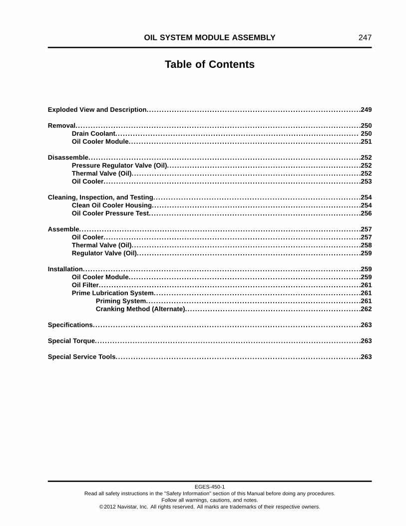
OIL SYSTEM MODULE ASSEMBLY 247
Table of Contents
Exploded View and Description. . . . . . . . . . . . . . . . . . . . . . . . . . . . . . . . . . . . . . . . . . . . . . . . . . . . . . . . . . . . . . . . . . . . . . . . . . . . . . . . . . . . .249
Removal. . . . . . . . . . . . . . . . . . . . . . . . . . . . . . . . . . . . . . . . . . . . . . . . . . . . . . . . . . . . . . . . . . . . . . . . . . . . . . . . . . . . . . . . . . . . . . . . . . . . . . . . . . . . . . . . .250Drain Coolant. . . . . . . . . . . . . . . . . . . . . . . . . . . . . . . . . . . . . . . . . . . . . . . . . . . . . . . . . . . . . . . . . . . . . . . . . . . . . . . . . . . . . . . . . . . . . . . . . 250Oil Cooler Module. . . . . . . . . . . . . . . . . . . . . . . . . . . . . . . . . . . . . . . . . . . . . . . . . . . . . . . . . . . . . . . . . . . . . . . . . . . . . . . . . . . . . . . . . . . .251
Disassemble. . . . . . . . . . . . . . . . . . . . . . . . . . . . . . . . . . . . . . . . . . . . . . . . . . . . . . . . . . . . . . . . . . . . . . . . . . . . . . . . . . . . . . . . . . . . . . . . . . . . . . . . . . . .252Pressure Regulator Valve (Oil). . . . . . . . . . . . . . . . . . . . . . . . . . . . . . . . . . . . . . . . . . . . . . . . . . . . . . . . . . . . . . . . . . . . . . . . . . . . .252Thermal Valve (Oil). . . . . . . . . . . . . . . . . . . . . . . . . . . . . . . . . . . . . . . . . . . . . . . . . . . . . . . . . . . . . . . . . . . . . . . . . . . . . . . . . . . . . . . . . . .252Oil Cooler. . . . . . . . . . . . . . . . . . . . . . . . . . . . . . . . . . . . . . . . . . . . . . . . . . . . . . . . . . . . . . . . . . . . . . . . . . . . . . . . . . . . . . . . . . . . . . . . . . . . . .253
Cleaning, Inspection, and Testing. . . . . . . . . . . . . . . . . . . . . . . . . . . . . . . . . . . . . . . . . . . . . . . . . . . . . . . . . . . . . . . . . . . . . . . . . . . . . . . . . .254Clean Oil Cooler Housing.. . . . . . . . . . . . . . . . . . . . . . . . . . . . . . . . . . . . . . . . . . . . . . . . . . . . . . . . . . . . . . . . . . . . . . . . . . . . . . . . . .254Oil Cooler Pressure Test. . . . . . . . . . . . . . . . . . . . . . . . . . . . . . . . . . . . . . . . . . . . . . . . . . . . . . . . . . . . . . . . . . . . . . . . . . . . . . . . . . . .256
Assemble. . . . . . . . . . . . . . . . . . . . . . . . . . . . . . . . . . . . . . . . . . . . . . . . . . . . . . . . . . . . . . . . . . . . . . . . . . . . . . . . . . . . . . . . . . . . . . . . . . . . . . . . . . . . . . . .257Oil Cooler. . . . . . . . . . . . . . . . . . . . . . . . . . . . . . . . . . . . . . . . . . . . . . . . . . . . . . . . . . . . . . . . . . . . . . . . . . . . . . . . . . . . . . . . . . . . . . . . . . . . . .257Thermal Valve (Oil). . . . . . . . . . . . . . . . . . . . . . . . . . . . . . . . . . . . . . . . . . . . . . . . . . . . . . . . . . . . . . . . . . . . . . . . . . . . . . . . . . . . . . . . . . .258Regulator Valve (Oil). . . . . . . . . . . . . . . . . . . . . . . . . . . . . . . . . . . . . . . . . . . . . . . . . . . . . . . . . . . . . . . . . . . . . . . . . . . . . . . . . . . . . . . . .259
Installation. . . . . . . . . . . . . . . . . . . . . . . . . . . . . . . . . . . . . . . . . . . . . . . . . . . . . . . . . . . . . . . . . . . . . . . . . . . . . . . . . . . . . . . . . . . . . . . . . . . . . . . . . . . . . .259Oil Cooler Module. . . . . . . . . . . . . . . . . . . . . . . . . . . . . . . . . . . . . . . . . . . . . . . . . . . . . . . . . . . . . . . . . . . . . . . . . . . . . . . . . . . . . . . . . . . .259Oil Filter. . . . . . . . . . . . . . . . . . . . . . . . . . . . . . . . . . . . . . . . . . . . . . . . . . . . . . . . . . . . . . . . . . . . . . . . . . . . . . . . . . . . . . . . . . . . . . . . . . . . . . . .261Prime Lubrication System.. . . . . . . . . . . . . . . . . . . . . . . . . . . . . . . . . . . . . . . . . . . . . . . . . . . . . . . . . . . . . . . . . . . . . . . . . . . . . . . . .261
Priming System.. . . . . . . . . . . . . . . . . . . . . . . . . . . . . . . . . . . . . . . . . . . . . . . . . . . . . . . . . . . . . . . . . . . . . . . . . . . . . . . . . . . .261Cranking Method (Alternate). . . . . . . . . . . . . . . . . . . . . . . . . . . . . . . . . . . . . . . . . . . . . . . . . . . . . . . . . . . . . . . . . . . . . .262
Specifications. . . . . . . . . . . . . . . . . . . . . . . . . . . . . . . . . . . . . . . . . . . . . . . . . . . . . . . . . . . . . . . . . . . . . . . . . . . . . . . . . . . . . . . . . . . . . . . . . . . . . . . . . .263
Special Torque.. . . . . . . . . . . . . . . . . . . . . . . . . . . . . . . . . . . . . . . . . . . . . . . . . . . . . . . . . . . . . . . . . . . . . . . . . . . . . . . . . . . . . . . . . . . . . . . . . . . . . . . . .263
Special Service Tools. . . . . . . . . . . . . . . . . . . . . . . . . . . . . . . . . . . . . . . . . . . . . . . . . . . . . . . . . . . . . . . . . . . . . . . . . . . . . . . . . . . . . . . . . . . . . . . . .263
EGES-450-1Read all safety instructions in the "Safety Information" section of this Manual before doing any procedures.
Follow all warnings, cautions, and notes.©2012 Navistar, Inc. All rights reserved. All marks are trademarks of their respective owners.

248 OIL SYSTEM MODULE ASSEMBLY
EGES-450-1Read all safety instructions in the "Safety Information" section of this Manual before doing any procedures.
Follow all warnings, cautions, and notes.©2012 Navistar, Inc. All rights reserved. All marks are trademarks of their respective owners.

OIL SYSTEM MODULE ASSEMBLY 249
Exploded View and Description
Figure 310 Oil cooler module assembly
1. Pressure regulator valve cap2. O-ring, 2.9 x 29.6 I.D. (pressure
regulator valve)3. Pressure regulator valve spring4. Pressure regulator valve piston5. O-ring gasket (thermal valve
assembly)6. Thermal valve assembly7. M8 x 25 screw (2)8. Oil cooler housing
9. Housing to crankcase gasket(oil)
10. Housing to crankcase gasket(coolant)
11. M8 serrated nut (2)12. Seal (coolant return cooler tube)13. O-ring, 2.2 x 13.3 I.D.14. M16 plug (coolant drain)15. Cooler to housing gasket -
coolant (2)
16. Cooler to housing gasket - oil (2)17. M8 x 25 screw (8)18. Oil cooler19. M8 x 15 stud bolt20. Oil filter adapter21. M12 plug22. Seal23. Fitting & O-ring (with screen)
(turbocharger oil supply)24. M8 x 30 bolt (13)
EGES-450-1Read all safety instructions in the "Safety Information" section of this Manual before doing any procedures.
Follow all warnings, cautions, and notes.©2012 Navistar, Inc. All rights reserved. All marks are trademarks of their respective owners.

250 OIL SYSTEM MODULE ASSEMBLY
The oil cooler module assembly uses engine coolant,an oil cooler, and a thermal valve to cool engine oil. Anoil pressure regulator valve dumps excess oil to theoil pan to regulate oil pressure and an oil filter filtersengine oil. See Engine Lubrication System (page36) for additional lubrication system information.
Removal
GOVERNMENT REGULATION: Enginefluids (oil, fuel, and coolant) may be a hazardto human health and the environment.Handle all fluids and other contaminatedmaterials (e.g. filters, rags) in accordancewith applicable regulations. Recycleor dispose of engine fluids, filters, andother contaminated materials according toapplicable regulations.
WARNING: To prevent personal injury ordeath, read all safety instructions in the “SafetyInformation” section of this manual.
WARNING: To prevent personal injury ordeath, shift transmission to park or neutral, setparking brake, and block wheels before doingdiagnostic or service procedures.
WARNING: To prevent personal injury ordeath, do not let engine fluids stay on your skin.Clean skin and nails using hand cleaner and washwith soap and water. Wash or discard clothingand rags contaminated with engine fluids.
WARNING: To prevent personal injury ordeath, wear safety glasses with side shields.Limit compressed air pressure to 207 kPa (30 psi).
Drain Coolant
WARNING: To prevent personal injury ordeath, allow engine to cool before drainingcoolant.
Figure 311 Coolant drain plug
1. Place a coolant drain pan under the oil coolermodule.
2. Remove M16 coolant drain plug from the bottomof the oil cooler module. Open radiator cap toallow system to drain quicker.
3. Remove and discard coolant drain plug O-ring.
4. Inspect coolant drain plug, replace if necessary.
5. Lubricate a new coolant O-ring with clean coolant.Install O-ring onto the coolant drain plug.
6. After coolant has drained, install coolant drainplug into the oil cooler module.
7. Tighten coolant drain plug to special torque (page263).
8. Recycle or dispose of coolant according toapplicable regulations.
EGES-450-1Read all safety instructions in the "Safety Information" section of this Manual before doing any procedures.
Follow all warnings, cautions, and notes.©2012 Navistar, Inc. All rights reserved. All marks are trademarks of their respective owners.

OIL SYSTEM MODULE ASSEMBLY 251
Oil Cooler Module
NOTE: Components in the following figure have beenremoved for clarity of tube support locations.
Figure 312 Oil cooler module and coolant returntube
1. Oil cooler module2. Turbocharger oil supply tube3. M8 x 30 bolt (13)4. Coolant supply housing5. Tube support (3)6. Coolant return tube assembly7. M8 x 15 stud bolt8. Oil filter
1. Place a drain pan under the oil cooler moduleassembly.
2. Rotate oil filter counterclockwise with an oil filterwrench (page 263) and remove oil filter from oilcooler housing.
3. Remove the turbocharger oil supply tube from theoil cooler housing. See Turbocharger Oil SupplyTube Assembly (page 134).
4. Discard turbocharger oil supply tube O-ring.
5. Cap the open ends of the turbocharger oil supplytube and fitting.
6. Loosen and back out, do not remove, one M8x 30 bolt securing the closest tube support forthe coolant return tube assembly to the oil coolermodule.
7. Remove, do not discard, one M8 x 15 stud boltfrom the oil cooler module.
8. Remove ten M8 x 30 bolts securing the oil coolermodule to the crankcase. Pull oil cooler moduleslightly away from the crankcase, then remove thecoolant return tube.
9. Discard O-ring from the coolant return tube.
10. Remove three M8 x 30 bolts and remove coolantreturn tube from the coolant supply housing.
11. Recycle or dispose of oil filter, oil, and coolantaccording to applicable regulations.
Figure 313 Oil cooler housing gaskets
1. Housing to crankcase gasket (coolant)2. Housing to crankcase gasket (oil)
12. Remove and discard both the housing tocrankcase coolant gaskets.
EGES-450-1Read all safety instructions in the "Safety Information" section of this Manual before doing any procedures.
Follow all warnings, cautions, and notes.©2012 Navistar, Inc. All rights reserved. All marks are trademarks of their respective owners.

252 OIL SYSTEM MODULE ASSEMBLY
DisassemblePressure Regulator Valve (Oil)
Figure 314 Pressure regulator valve removal
1. Pressure regulator valve cap with O-ring2. Pressure regulator valve spring3. Pressure regulator valve piston4. Oil cooler5. Oil cooler housing
1. Remove pressure regulator valve cap from the oilcooler housing.
2. Remove and discard pressure regulator valve capO-ring.
3. Inspect pressure regulator valve cap. If damagedor corroded, replace.
4. Remove pressure regulator spring and pistonfrom oil cooler housing.
5. Inspect spring and piston. If damaged, replace.
Thermal Valve (Oil)
Figure 315 Thermal valve removal
1. Oil cooler housing2. Thermal valve3. M8 x 25 screw (2)4. O-ring5. Oil cooler
1. Loosen and remove, do not discard two M8 x25 screws securing thermal valve to oil coolerhousing.
2. Remove thermal valve from oil cooler housing.
3. Remove and discard thermal valve O-ring.
EGES-450-1Read all safety instructions in the "Safety Information" section of this Manual before doing any procedures.
Follow all warnings, cautions, and notes.©2012 Navistar, Inc. All rights reserved. All marks are trademarks of their respective owners.

OIL SYSTEM MODULE ASSEMBLY 253
Oil Cooler
Figure 316 Oil cooler removal
1. Oil cooler housing2. Oil cooler3. M8 x 25 screw (8)
1. Loosen and remove, do not discard, eight M8 x25 screws securing the oil cooler to the oil coolerhousing.
Figure 317 Oil cooler mounting nuts
1. Oil cooler housing2. M8 serrated nut (2)3. Oil cooler
2. Flip oil cooler housing over and remove, do notdiscard, two M8 serrated nuts securing the oilcooler to the oil cooler housing.
CAUTION: To prevent engine damage, do not useexcessive force against aluminum cooler plate toseparate oil cooler from oil cooler housing. Do notapply any force to oil cooler fins.
Figure 318 Oil cooler separation point
1. Oil cooler2. Oil cooler housing
3. Separate oil cooler from the oil cooler housingby applying just enough force at large arrow forseparation.
4. Drain oil and coolant out of oil cooler.
EGES-450-1Read all safety instructions in the "Safety Information" section of this Manual before doing any procedures.
Follow all warnings, cautions, and notes.©2012 Navistar, Inc. All rights reserved. All marks are trademarks of their respective owners.

254 OIL SYSTEM MODULE ASSEMBLY
Figure 319 Oil cooler seals
1. Oil cooler housing2. Oil cooler to housing gasket - oil (2)3. Oil cooler to housing gasket - coolant (2)4. M12 plug with seal
5. Remove and discard two oil cooler housinggaskets for oil and two oil cooler housing gasketsfor coolant from oil cooler housing.
6. Remove M12 plug and seal. Discard seal
Cleaning, Inspection, and Testing
WARNING: To prevent personal injury ordeath, wear safety glasses with side shields.Limit compressed air pressure to 207 kPa (30 psi).
Clean Oil Cooler Housing
CAUTION: To prevent engine damage, replace the oilcooler if an engine bearing fails. Bearing debris cannot be removed from the oil cooler.
CAUTION: To prevent engine damage, do not cleanthe assembled oil cooler housing in solvent. Solventwill be trapped in the oil cooler, regulator valveassembly, and thermal valve assembly.
If not already done, remove the following componentsfrom the oil cooler housing before cleaning withsolvent:
• Oil cooler
• Regulator valve assembly
• Thermal valve assembly
• Fitting & O-ring (with screen)
• All plugs and O-rings
Figure 320 Fitting & O-ring (with screen)(turbocharger oil supply)
1. Fitting & O-ring (with screen)2. Oil cooler housing
EGES-450-1Read all safety instructions in the "Safety Information" section of this Manual before doing any procedures.
Follow all warnings, cautions, and notes.©2012 Navistar, Inc. All rights reserved. All marks are trademarks of their respective owners.

OIL SYSTEM MODULE ASSEMBLY 255
CAUTION: To prevent turbocharger damage,turbocharger oil supply fitting filter screen mustbe clean.
1. Remove fitting & O-ring (with screen)(turbocharger oil supply) from side of oilcooler housing. Remove and discard O-ring fromfitting.
Figure 321 Fitting & O-ring (with screen)(turbocharger oil supply)
1. Direction of oil flow2. Wire mesh screen
2. Inspect wire mesh screen for damage or particleobstruction. Clean or replace fitting if necessary.
3. The oil cooler housing can be cleaned in solventand blown dry with filtered compressed air asfollows:
• Clean the disassembled oil cooler housing ina suitable solvent.
• Flush and drain oil cooler housing to removeany residue. Dry oil cooler housing withfiltered compressed air.
• Check oil cooler housing for blocked orificesand damaged threads. Replace housing ifrequired.
4. Once oil cooler housing has been cleaned andinspected or a new oil cooler housing is to beused, lubricate a new O-ring with clean engine oiland install onto fitting with screen.
5. Install fitting into oil cooler housing and fingertighten.
6. Tighten fitting (turbocharger oil supply tube) tospecial torque (page 263).
EGES-450-1Read all safety instructions in the "Safety Information" section of this Manual before doing any procedures.
Follow all warnings, cautions, and notes.©2012 Navistar, Inc. All rights reserved. All marks are trademarks of their respective owners.
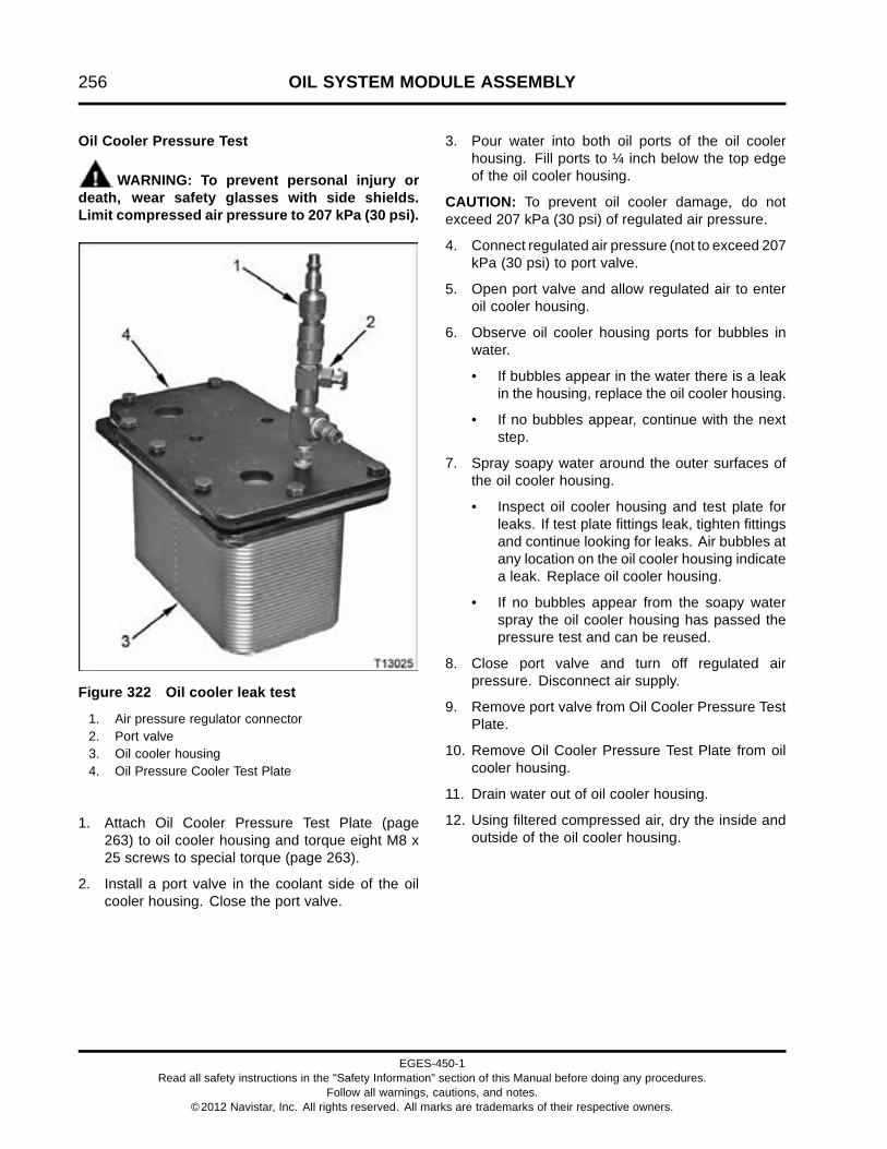
256 OIL SYSTEM MODULE ASSEMBLY
Oil Cooler Pressure Test
WARNING: To prevent personal injury ordeath, wear safety glasses with side shields.Limit compressed air pressure to 207 kPa (30 psi).
Figure 322 Oil cooler leak test
1. Air pressure regulator connector2. Port valve3. Oil cooler housing4. Oil Pressure Cooler Test Plate
1. Attach Oil Cooler Pressure Test Plate (page263) to oil cooler housing and torque eight M8 x25 screws to special torque (page 263).
2. Install a port valve in the coolant side of the oilcooler housing. Close the port valve.
3. Pour water into both oil ports of the oil coolerhousing. Fill ports to ¼ inch below the top edgeof the oil cooler housing.
CAUTION: To prevent oil cooler damage, do notexceed 207 kPa (30 psi) of regulated air pressure.
4. Connect regulated air pressure (not to exceed 207kPa (30 psi) to port valve.
5. Open port valve and allow regulated air to enteroil cooler housing.
6. Observe oil cooler housing ports for bubbles inwater.
• If bubbles appear in the water there is a leakin the housing, replace the oil cooler housing.
• If no bubbles appear, continue with the nextstep.
7. Spray soapy water around the outer surfaces ofthe oil cooler housing.
• Inspect oil cooler housing and test plate forleaks. If test plate fittings leak, tighten fittingsand continue looking for leaks. Air bubbles atany location on the oil cooler housing indicatea leak. Replace oil cooler housing.
• If no bubbles appear from the soapy waterspray the oil cooler housing has passed thepressure test and can be reused.
8. Close port valve and turn off regulated airpressure. Disconnect air supply.
9. Remove port valve from Oil Cooler Pressure TestPlate.
10. Remove Oil Cooler Pressure Test Plate from oilcooler housing.
11. Drain water out of oil cooler housing.
12. Using filtered compressed air, dry the inside andoutside of the oil cooler housing.
EGES-450-1Read all safety instructions in the "Safety Information" section of this Manual before doing any procedures.
Follow all warnings, cautions, and notes.©2012 Navistar, Inc. All rights reserved. All marks are trademarks of their respective owners.

OIL SYSTEM MODULE ASSEMBLY 257
AssembleOil Cooler
Figure 323 Oil cooler seals and oil cooler
1. Oil cooler housing2. Oil cooler to housing gasket - oil (2)3. Oil cooler to housing gasket - coolant (2)4. Oil cooler5. Oil cooler alignment studs (part of cooler)
1. Place oil cooler housing onto a clean work bench,flat side down.
2. Lubricate two new oil cooler housing gaskets foroil with clean engine oil and install into the oilcooler housing recess.
3. Lubricate two new oil cooler housing gaskets forcoolant with clean coolant and install into the oilcooler housing recess.
4. Align oil cooler over oil cooler housing. Insert oilcooler studs through oil cooler housing and pushdown onto the oil cooler.
Figure 324 Oil cooler
1. Oil cooler housing2. Oil cooler3. M8 x 25 screw (8)
CAUTION: To prevent engine damage, do not usepower tools to install oil cooler screws.
5. Install eight M8 x 25 screws to the oil cooler andoil cooler housing. Finger tighten screws.
6. Tighten oil cooler mounting screws to specialtorque (page 263).
EGES-450-1Read all safety instructions in the "Safety Information" section of this Manual before doing any procedures.
Follow all warnings, cautions, and notes.©2012 Navistar, Inc. All rights reserved. All marks are trademarks of their respective owners.

258 OIL SYSTEM MODULE ASSEMBLY
Figure 325 Oil cooler mounting nuts
1. Oil cooler housing2. M8 serrated nut (2)3. Oil cooler
7. Flip oil cooler housing and oil cooler over andinstall two M8 serrated nuts to the oil cooler studssticking through the oil cooler housing. Fingertighten M8 serrated nuts.
8. Tighten two M8 serrated nuts to special torque(page 263).
Thermal Valve (Oil)
Figure 326 Thermal valve
1. Oil cooler housing2. Thermal valve3. M8 x 25 screw (2)4. O-ring5. Oil cooler
1. Lubricate a new O-ring with clean engine oil.Install O-ring onto thermal valve.
2. Install thermal valve into oil cooler housing.
3. Secure with two M8 x 25 screws. Finger tightenscrews.
4. Tighten two M8 x 25 screws to special torque(page 263).
EGES-450-1Read all safety instructions in the "Safety Information" section of this Manual before doing any procedures.
Follow all warnings, cautions, and notes.©2012 Navistar, Inc. All rights reserved. All marks are trademarks of their respective owners.

OIL SYSTEM MODULE ASSEMBLY 259
Regulator Valve (Oil)
Figure 327 Pressure regulator valve (oil)
1. Pressure regulator valve cap with O-ring2. Pressure regulator valve spring3. Pressure regulator valve piston4. Oil cooler5. Oil cooler housing
1. Install pressure regulator valve piston and springinto oil cooler housing.
2. Lubricate new O-ring with clean engine oil andinstall onto pressure regulator valve cap.
3. Install pressure regulator valve cap onto oil coolerhousing. Finger tighten cap.
4. Tighten pressure regulator valve cap (oil) tospecial torque (page 263).
InstallationOil Cooler Module
Figure 328 Oil cooler module gaskets
1. Housing to crankcase gasket - coolant2. Housing to crankcase gasket - oil
1. Lubricate a new housing to crankcase oil gasketwith clean engine oil and install into oil coolerhousing recess.
2. Lubricate a new housing to crankcase coolantgasket with clean coolant and install into oil coolerhousing recess.
3. Clean crankcase oil cooler housing matingsurface.
NOTE: Components in the following figure have beenremoved for clarity of tube support locations.
EGES-450-1Read all safety instructions in the "Safety Information" section of this Manual before doing any procedures.
Follow all warnings, cautions, and notes.©2012 Navistar, Inc. All rights reserved. All marks are trademarks of their respective owners.

260 OIL SYSTEM MODULE ASSEMBLY
Figure 329 Oil cooler module and coolant returntube
1. Oil cooler module2. Turbocharger oil supply tube3. M8 x 30 bolt (13)4. Coolant supply housing5. Tube support (3)6. Coolant return tube assembly7. M8 x 15 stud bolt
4. Lubricate a new O-ring for the coolant return tubewith clean coolant and install onto tube.
5. Install crankcase breather assembly, if removed.See Crankcase Ventilation System (page 476) formore information.
6. Install coolant return tube and three M8 x 30 boltsfinger tight.
7. Pull coolant return tube assembly outwardsenough to engage the oil cooler module. Slide oilcooler module onto coolant return tube, then alignbolt holes of oil cooler module with the mountingholes on the crankcase.
8. Place oil cooler module against crankcase andsecure with ten M8 x 30 bolts and one M8 x 30stud bolt. Finger tighten bolts.
9. Tighten M8 x 30 bolts and stud bolt to specialtorque (page 263).
10. Tighten three M8 x 30 bolts securing the coolantreturn tube assembly.
11. Uncap the open ends of the turbocharger oilsupply tube and fitting.
12. Install the turbocharger oil supply tube to the oilcooler module. See Turbocharger Oil SupplyTube Assembly (page 145).
13. Refill cooling system. See the appropriate VehicleOperator Manual for procedure and quantity ofcoolant.
EGES-450-1Read all safety instructions in the "Safety Information" section of this Manual before doing any procedures.
Follow all warnings, cautions, and notes.©2012 Navistar, Inc. All rights reserved. All marks are trademarks of their respective owners.

OIL SYSTEM MODULE ASSEMBLY 261
Oil Filter
Figure 330 Oil cooler module assembly
1. Oil cooler housing2. Oil cooler3. Oil filter
1. Lubricate new oil filter gasket with clean engineoil.
CAUTION: To prevent engine damage, install thecorrect oil filter for the engine application.
2. Install new oil filter on oil module housing. Verifycorrect oil filter is used.
• Standard oil filter (long filter)
• Front drive/steering axle oil filter (shorter filter)
CAUTION: To prevent engine damage, do not overtighten oil filter.
3. Hand tighten filter 2/3 to 1 full turn after gasket firstcontacts oil filter header.
CAUTION: To prevent engine damage, do not overfillengine with oil.
NOTE: The amount of oil used to refill the engine isdependent upon the service that was done.
4. Fill engine with the proper grade and viscosityof engine oil. See Engine Operation andMaintenance Manual for procedure and oil fillcapacities.
Prime Lubrication System
Priming System
CAUTION: To prevent engine damage, after completeengine overhaul, prime engine with oil before startingengine. This will lubricate internal engine componentsduring the critical initial startup phase.
NOTE: If only the oil cooler module was serviced,priming lubrication system is not required.
Figure 331 M12 plug assembly
1. Remove M12 plug assembly and pressurizelubrication system with sufficient engine oil tofill the oil filter and charge the entire lubricationsystem. See Engine Operation and MaintenanceManual for proper grade and viscosity of engineoil. Do not exceed total oil fill Specifications (page275)
2. Install M12 plug assembly and tighten to specialtorque (page 263).
3. Finish filling engine with oil. Remember tosubtract oil added during lubrication systempressurization and oil added directly to the oilfilter.
4. Start engine and check for leaks. If oil is leaking,turn off engine and repair leaks.
5. Turn off engine. Wait 15 minutes. Check oil leveland fill to the full mark.
EGES-450-1Read all safety instructions in the "Safety Information" section of this Manual before doing any procedures.
Follow all warnings, cautions, and notes.©2012 Navistar, Inc. All rights reserved. All marks are trademarks of their respective owners.

262 OIL SYSTEM MODULE ASSEMBLY
Cranking Method (Alternate)
CAUTION: To prevent engine damage, use thePressurization method to prime lubrication systemafter an engine overhaul.
1. Fill engine with oil. See Engine Operationand Maintenance Manual for proper grade andviscosity of engine oil. Do not exceed total oil fillSpecifications (page 275).
2. Disconnect Camshaft Position (CMP) sensorconnector.
3. Crank engine until the oil pressure gauge showssufficient oil pressure.
4. After oil pressure is evident in the lubricationsystem, reconnect CMP sensor connector andstart engine.
5. Start engine and check for leaks. Check for oilleaks. If oil is leaking turn off engine and repairleaks.
6. Turn off engine and clear CMP fault code. SeeEngine Diagnostic Manual.
7. Check oil level and fill to the full mark.
EGES-450-1Read all safety instructions in the "Safety Information" section of this Manual before doing any procedures.
Follow all warnings, cautions, and notes.©2012 Navistar, Inc. All rights reserved. All marks are trademarks of their respective owners.

OIL SYSTEM MODULE ASSEMBLY 263
Specifications
Oil cooler, all engines with front drive axle 33 plates
Oil cooler, MaxxForce® DT 23 plates
Oil cooler, MaxxForce® 9 and 10 33 plates
Oil pressure regulator valve, opening pressure 393 kPa (57 psi) @ 38 °C (100 °F)
Thermal valve, opening pressure 206 - 241 kPa (30 - 35 psi) @ 111 °C (232°F)
Special Torque
Coolant drain plug, M16 19 N·m (14 lbf·ft)
Coolant tube bracket bolts, M8 x 30 31 N·m (23 lbf·ft)
Fitting (turbocharger oil supply tube) 47 N·m (35 lbf·ft)
Oil filter adapter 80 N·m (59 lbf·ft)
Oil cooler module mounting bolts and stud bolt, M8 x 30 31 N·m (23 lbf·ft)
Oil cooler mounting screws, M8 x 25 23 N·m (17 lbf·ft)
Oil cooler M8 serrated nuts 22 N·m (16 lbf·ft)
Oil cooler pressure test plate mounting screws M8 x 25 23 N·m (17 lbf·ft)
Oil pressure regulator valve cap 70 N·m (51 lbf·ft)
Plug assembly, M12 5 N·m (46 lbf·in)
Thermal valve screws, M8 x 25 23 N·m (17 lbf·ft)
Special Service Tools
Air pressure regulator Obtain locally
Loctite® 272 Obtain locally
Oil Cooler Pressure Test Plate ZTSE4654
Oil filter wrench Obtain locally
EGES-450-1Read all safety instructions in the "Safety Information" section of this Manual before doing any procedures.
Follow all warnings, cautions, and notes.©2012 Navistar, Inc. All rights reserved. All marks are trademarks of their respective owners.
264 OIL SYSTEM MODULE ASSEMBLY
EGES-450-1Read all safety instructions in the "Safety Information" section of this Manual before doing any procedures.
Follow all warnings, cautions, and notes.©2012 Navistar, Inc. All rights reserved. All marks are trademarks of their respective owners.

OIL PAN AND OIL SUCTION TUBE 265
Table of Contents
Exploded Views.. . . . . . . . . . . . . . . . . . . . . . . . . . . . . . . . . . . . . . . . . . . . . . . . . . . . . . . . . . . . . . . . . . . . . . . . . . . . . . . . . . . . . . . . . . . . . . . . . . . . . . .267Front Sump.. . . . . . . . . . . . . . . . . . . . . . . . . . . . . . . . . . . . . . . . . . . . . . . . . . . . . . . . . . . . . . . . . . . . . . . . . . . . . . . . . . . . . . . . . . . . . . . . . . .267Rear Sump.. . . . . . . . . . . . . . . . . . . . . . . . . . . . . . . . . . . . . . . . . . . . . . . . . . . . . . . . . . . . . . . . . . . . . . . . . . . . . . . . . . . . . . . . . . . . . . . . . . . .268
Removal. . . . . . . . . . . . . . . . . . . . . . . . . . . . . . . . . . . . . . . . . . . . . . . . . . . . . . . . . . . . . . . . . . . . . . . . . . . . . . . . . . . . . . . . . . . . . . . . . . . . . . . . . . . . . . . . .269Drain Engine Oil. . . . . . . . . . . . . . . . . . . . . . . . . . . . . . . . . . . . . . . . . . . . . . . . . . . . . . . . . . . . . . . . . . . . . . . . . . . . . . . . . . . . . . . . . . . . . .269Oil Pan and Gasket. . . . . . . . . . . . . . . . . . . . . . . . . . . . . . . . . . . . . . . . . . . . . . . . . . . . . . . . . . . . . . . . . . . . . . . . . . . . . . . . . . . . . . . . . . .269Suction Tube Assembly. . . . . . . . . . . . . . . . . . . . . . . . . . . . . . . . . . . . . . . . . . . . . . . . . . . . . . . . . . . . . . . . . . . . . . . . . . . . . . . . . . . . .270
Cleaning and Inspecting. . . . . . . . . . . . . . . . . . . . . . . . . . . . . . . . . . . . . . . . . . . . . . . . . . . . . . . . . . . . . . . . . . . . . . . . . . . . . . . . . . . . . . . . . . . . . .271Oil Pan and Suction Tube. . . . . . . . . . . . . . . . . . . . . . . . . . . . . . . . . . . . . . . . . . . . . . . . . . . . . . . . . . . . . . . . . . . . . . . . . . . . . . . . . . .271
Installation. . . . . . . . . . . . . . . . . . . . . . . . . . . . . . . . . . . . . . . . . . . . . . . . . . . . . . . . . . . . . . . . . . . . . . . . . . . . . . . . . . . . . . . . . . . . . . . . . . . . . . . . . . . . . .272Suction Tube Assembly. . . . . . . . . . . . . . . . . . . . . . . . . . . . . . . . . . . . . . . . . . . . . . . . . . . . . . . . . . . . . . . . . . . . . . . . . . . . . . . . . . . . .272Oil Pan and Gasket. . . . . . . . . . . . . . . . . . . . . . . . . . . . . . . . . . . . . . . . . . . . . . . . . . . . . . . . . . . . . . . . . . . . . . . . . . . . . . . . . . . . . . . . . . .273Fill Engine with Oil. . . . . . . . . . . . . . . . . . . . . . . . . . . . . . . . . . . . . . . . . . . . . . . . . . . . . . . . . . . . . . . . . . . . . . . . . . . . . . . . . . . . . . . . . . .274
Specifications. . . . . . . . . . . . . . . . . . . . . . . . . . . . . . . . . . . . . . . . . . . . . . . . . . . . . . . . . . . . . . . . . . . . . . . . . . . . . . . . . . . . . . . . . . . . . . . . . . . . . . . . . .275
Special Torque.. . . . . . . . . . . . . . . . . . . . . . . . . . . . . . . . . . . . . . . . . . . . . . . . . . . . . . . . . . . . . . . . . . . . . . . . . . . . . . . . . . . . . . . . . . . . . . . . . . . . . . . . .275
Special Service Tools. . . . . . . . . . . . . . . . . . . . . . . . . . . . . . . . . . . . . . . . . . . . . . . . . . . . . . . . . . . . . . . . . . . . . . . . . . . . . . . . . . . . . . . . . . . . . . . . .275
EGES-450-1Read all safety instructions in the "Safety Information" section of this Manual before doing any procedures.
Follow all warnings, cautions, and notes.©2012 Navistar, Inc. All rights reserved. All marks are trademarks of their respective owners.

266 OIL PAN AND OIL SUCTION TUBE
EGES-450-1Read all safety instructions in the "Safety Information" section of this Manual before doing any procedures.
Follow all warnings, cautions, and notes.©2012 Navistar, Inc. All rights reserved. All marks are trademarks of their respective owners.

OIL PAN AND OIL SUCTION TUBE 267
Exploded ViewsFront Sump
Figure 332 Oil pan and oil suction tube (front sump)
1. Oil suction tube gasket2. Oil pan gasket3. M10 x 25 bolt4. Oil pan end rail stiffener (2)5. M8 x 24 bolt (18)6. Oil pan rail stiffener (2)
7. Drain plug gasket8. Heater element (optional)9. Flanged hex head plug (M25 x
1.5, without oil pan heater)10. Flanged hex head plug (oil drain
plug)
11. O-ring seal, #21312. Oil pan (front sump)13. M8 x 35 bolt (2)14. Front sump suction tube
assembly
EGES-450-1Read all safety instructions in the "Safety Information" section of this Manual before doing any procedures.
Follow all warnings, cautions, and notes.©2012 Navistar, Inc. All rights reserved. All marks are trademarks of their respective owners.
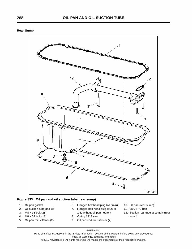
268 OIL PAN AND OIL SUCTION TUBE
Rear Sump
Figure 333 Oil pan and oil suction tube (rear sump)
1. Oil pan gasket2. Oil suction tube gasket3. M8 x 35 bolt (2)4. M8 x 24 bolt (18)5. Oil pan rail stiffener (2)
6. Flanged hex head plug (oil drain)7. Flanged hex head plug (M25 x
1.5, without oil pan heater)8. O-ring #213 seal9. Oil pan end rail stiffener (2)
10. Oil pan (rear sump)11. M10 x 70 bolt12. Suction rear tube assembly (rear
sump)
EGES-450-1Read all safety instructions in the "Safety Information" section of this Manual before doing any procedures.
Follow all warnings, cautions, and notes.©2012 Navistar, Inc. All rights reserved. All marks are trademarks of their respective owners.
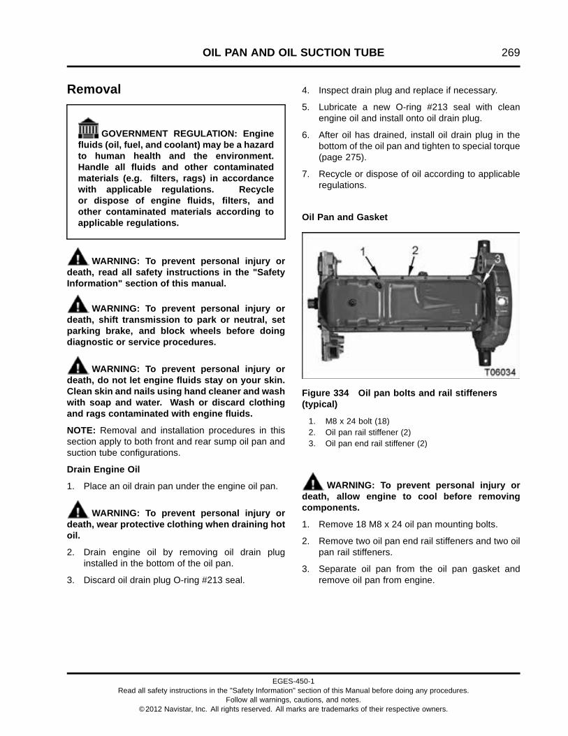
OIL PAN AND OIL SUCTION TUBE 269
Removal
GOVERNMENT REGULATION: Enginefluids (oil, fuel, and coolant) may be a hazardto human health and the environment.Handle all fluids and other contaminatedmaterials (e.g. filters, rags) in accordancewith applicable regulations. Recycleor dispose of engine fluids, filters, andother contaminated materials according toapplicable regulations.
WARNING: To prevent personal injury ordeath, read all safety instructions in the "SafetyInformation" section of this manual.
WARNING: To prevent personal injury ordeath, shift transmission to park or neutral, setparking brake, and block wheels before doingdiagnostic or service procedures.
WARNING: To prevent personal injury ordeath, do not let engine fluids stay on your skin.Clean skin and nails using hand cleaner and washwith soap and water. Wash or discard clothingand rags contaminated with engine fluids.
NOTE: Removal and installation procedures in thissection apply to both front and rear sump oil pan andsuction tube configurations.
Drain Engine Oil
1. Place an oil drain pan under the engine oil pan.
WARNING: To prevent personal injury ordeath, wear protective clothing when draining hotoil.
2. Drain engine oil by removing oil drain pluginstalled in the bottom of the oil pan.
3. Discard oil drain plug O-ring #213 seal.
4. Inspect drain plug and replace if necessary.
5. Lubricate a new O-ring #213 seal with cleanengine oil and install onto oil drain plug.
6. After oil has drained, install oil drain plug in thebottom of the oil pan and tighten to special torque(page 275).
7. Recycle or dispose of oil according to applicableregulations.
Oil Pan and Gasket
Figure 334 Oil pan bolts and rail stiffeners(typical)
1. M8 x 24 bolt (18)2. Oil pan rail stiffener (2)3. Oil pan end rail stiffener (2)
WARNING: To prevent personal injury ordeath, allow engine to cool before removingcomponents.
1. Remove 18 M8 x 24 oil pan mounting bolts.
2. Remove two oil pan end rail stiffeners and two oilpan rail stiffeners.
3. Separate oil pan from the oil pan gasket andremove oil pan from engine.
EGES-450-1Read all safety instructions in the "Safety Information" section of this Manual before doing any procedures.
Follow all warnings, cautions, and notes.©2012 Navistar, Inc. All rights reserved. All marks are trademarks of their respective owners.

270 OIL PAN AND OIL SUCTION TUBE
Figure 335 Oil pan gasket, RTV sealant locations, and suction tube assembly (front sump, typical)
1. Oil pan gasket2. RTV sealant locations3. M10 x 25 bolt (front sump)
4. Oil pan gasket dowel (intocrankcase)
5. M8 x 35 bolt (2)
4. To preserve the gasket, cut through RTV sealantunder the oil pan gasket at indicated locations onthe oil pan mounting surface using a flat gasketscraper or similar tool. Cut parallel to the gasketpath.
NOTE: The oil pan gasket is reusable if it is notcracked and the sealing surface is in good condition.
5. Remove the oil pan gasket from the front cover,flywheel housing, and crankcase. To ensuregasket reusability, carefully remove any residualRTV from gasket surface.
Suction Tube Assembly
1. Remove M10 bolt holding the suction tube bracketto the crankcase.
2. Remove two M8 x 35 bolts connecting the suctiontube assembly to the front cover.
3. Remove the suction tube assembly and discardgasket.
Figure 336 Suction tube assembly and gasket(typical)
1. Suction tube assembly2. Suction tube gasket
EGES-450-1Read all safety instructions in the "Safety Information" section of this Manual before doing any procedures.
Follow all warnings, cautions, and notes.©2012 Navistar, Inc. All rights reserved. All marks are trademarks of their respective owners.

OIL PAN AND OIL SUCTION TUBE 271
Cleaning and InspectingOil Pan and Suction Tube
1. Remove RTV sealant from the crankcase, oil pan,front cover, and flywheel housing mating surfaceswith a flat scraper. Scrape parallel to the gasketpath.
2. Clean the oil pan, front cover, flywheel housing,suction tube assembly, and crankcase matingsurfaces thoroughly with a suitable solvent.
3. Clean and inspect the oil pan gasket. Inspectgasket for cracks or damaged sealing surface toverify gasket reusability. If gasket is damaged,discard and replace with new gasket.
4. Clean and inspect the oil suction tube assembly.Make sure the suction tube is free of obstructions,cracks, or other damage.
5. Check the oil pan for cracks and damage.Replace components if necessary.
EGES-450-1Read all safety instructions in the "Safety Information" section of this Manual before doing any procedures.
Follow all warnings, cautions, and notes.©2012 Navistar, Inc. All rights reserved. All marks are trademarks of their respective owners.

272 OIL PAN AND OIL SUCTION TUBE
InstallationSuction Tube Assembly
Figure 337 Suction tube assembly and gasket(typical)
1. Suction tube assembly2. Suction tube gasket
1. Install suction tube assembly and a new gasketon the front cover and finger tighten two M8 x 35bolts.
Figure 338 Installing suction tube assembly(typical)
2. Install one M10 bolt connecting the oil suctiontube mounting bracket to the crankcase and fingertighten.
3. Tighten two M8 x 35 bolts to special torque (page275).
4. Tighten M10 bolt to standard torque (page 523).
EGES-450-1Read all safety instructions in the "Safety Information" section of this Manual before doing any procedures.
Follow all warnings, cautions, and notes.©2012 Navistar, Inc. All rights reserved. All marks are trademarks of their respective owners.

OIL PAN AND OIL SUCTION TUBE 273
Oil Pan and Gasket
1. If removed, install flywheel housing (page395) before oil pan.
2. If removed, install front cover (page 302) beforeoil pan.
Figure 339 Oil pan gasket mounting surface (typical)
1. RTV sealant locations 2. Oil pan gasket dowel hole
CAUTION: Install components and tighten bolts within5 minutes of Liquid Gasket (RTV) application.
3. Apply a 6 mm (0.25 in) bead of Wacker® T –442 RTV sealant (page 275) to the six locationson the oil pan mounting surface. These locationscoincide with gasket joints between the front coverhalves, crankcase, and flywheel housing.
4. Before the RTV sealant dries, install a clean oilpan gasket on the crankcase mounting surface.Make sure the oil pan gasket dowel is aligned withthe hole in the crankcase mounting surface.
5. Install the oil pan on the crankcase.
EGES-450-1Read all safety instructions in the "Safety Information" section of this Manual before doing any procedures.
Follow all warnings, cautions, and notes.©2012 Navistar, Inc. All rights reserved. All marks are trademarks of their respective owners.

274 OIL PAN AND OIL SUCTION TUBE
Figure 340 Oil pan, bolts, and rail stiffeners(typical)
1. M8 x 24 bolt (18)2. Oil pan rail stiffener (2)3. Oil pan end rail stiffener (2)
6. Install two oil pan end rail stiffeners and two oilpan rail stiffeners on the oil pan.
7. Install 18 M8 x 24 oil pan mounting bolts fingertight.
8. Tighten M8 x 24 bolts to special torque (page275).
Fill Engine with Oil
CAUTION: To prevent engine damage, after engineor lubrication system service, prime engine with oil(page 261) before starting engine. This will lubricateinternal engine components during the critical initialstartup phase.
1. Fill engine with the proper grade, viscosity, andquantity of engine oil. See Engine Operation andMaintenance Manual. Do not exceed engine oilSpecifications (page 275).
2. Start engine and check for oil leaks. If oil isleaking, turn off engine, repair leaks, and repeatstep.
3. Turn off engine.
4. Wait 15 minutes. Check oil level and fill to the fullmark.
EGES-450-1Read all safety instructions in the "Safety Information" section of this Manual before doing any procedures.
Follow all warnings, cautions, and notes.©2012 Navistar, Inc. All rights reserved. All marks are trademarks of their respective owners.

OIL PAN AND OIL SUCTION TUBE 275
Specifications
Lube system capacity (after rebuild and new filter) 32 L (34 quarts US)
Lube system capacity (after oil drain and filter change) 28 L (30 quarts US)
Special Torque
Oil pan drain plug 68 N·m (50 lbf·ft)
Oil pan heater plug 68 N·m (50 lbf·ft)
Oil pan mounting bolts, M8 x 24 32 N·m (24 lbf·ft)
Oil suction tube bolts, M8 x 35 27 N·m (20 lbf·ft)
Special Service Tools
Wacker® T – 442 RTV sealant Obtain locally
EGES-450-1Read all safety instructions in the "Safety Information" section of this Manual before doing any procedures.
Follow all warnings, cautions, and notes.©2012 Navistar, Inc. All rights reserved. All marks are trademarks of their respective owners.

276 OIL PAN AND OIL SUCTION TUBE
EGES-450-1Read all safety instructions in the "Safety Information" section of this Manual before doing any procedures.
Follow all warnings, cautions, and notes.©2012 Navistar, Inc. All rights reserved. All marks are trademarks of their respective owners.

FRONT COVER, COOLING SYSTEM, AND RELATED COMPONENTS 277
Table of Contents
Exploded View.. . . . . . . . . . . . . . . . . . . . . . . . . . . . . . . . . . . . . . . . . . . . . . . . . . . . . . . . . . . . . . . . . . . . . . . . . . . . . . . . . . . . . . . . . . . . . . . . . . . . . . . . .280
Removal. . . . . . . . . . . . . . . . . . . . . . . . . . . . . . . . . . . . . . . . . . . . . . . . . . . . . . . . . . . . . . . . . . . . . . . . . . . . . . . . . . . . . . . . . . . . . . . . . . . . . . . . . . . . . . . . .282Dual Drive Belt. . . . . . . . . . . . . . . . . . . . . . . . . . . . . . . . . . . . . . . . . . . . . . . . . . . . . . . . . . . . . . . . . . . . . . . . . . . . . . . . . . . . . . . . . . . . . . . .282Single Drive Belt. . . . . . . . . . . . . . . . . . . . . . . . . . . . . . . . . . . . . . . . . . . . . . . . . . . . . . . . . . . . . . . . . . . . . . . . . . . . . . . . . . . . . . . . . . . . . .283Dual Idler Pulleys. . . . . . . . . . . . . . . . . . . . . . . . . . . . . . . . . . . . . . . . . . . . . . . . . . . . . . . . . . . . . . . . . . . . . . . . . . . . . . . . . . . . . . . . . . . . .284Alternator Support. . . . . . . . . . . . . . . . . . . . . . . . . . . . . . . . . . . . . . . . . . . . . . . . . . . . . . . . . . . . . . . . . . . . . . . . . . . . . . . . . . . . . . . . . . .285Secondary Compressor Support, Flat Idler Pulleys, and Idler Support Plate. . . . . . . . . . . . . . . . . . . . .286Coolant Supply Housing (Refrigerant Compressor Mount). . . . . . . . . . . . . . . . . . . . . . . . . . . . . . . . . . . . . . . . . . .287Water Outlet Tube and Thermostat. . . . . . . . . . . . . . . . . . . . . . . . . . . . . . . . . . . . . . . . . . . . . . . . . . . . . . . . . . . . . . . . . . . . . . . .287Water Pump Assembly. . . . . . . . . . . . . . . . . . . . . . . . . . . . . . . . . . . . . . . . . . . . . . . . . . . . . . . . . . . . . . . . . . . . . . . . . . . . . . . . . . . . . .288Water Inlet Elbow.. . . . . . . . . . . . . . . . . . . . . . . . . . . . . . . . . . . . . . . . . . . . . . . . . . . . . . . . . . . . . . . . . . . . . . . . . . . . . . . . . . . . . . . . . . . .288Fan Drive. . . . . . . . . . . . . . . . . . . . . . . . . . . . . . . . . . . . . . . . . . . . . . . . . . . . . . . . . . . . . . . . . . . . . . . . . . . . . . . . . . . . . . . . . . . . . . . . . . . . . . .289
Spin-on Fan Drive. . . . . . . . . . . . . . . . . . . . . . . . . . . . . . . . . . . . . . . . . . . . . . . . . . . . . . . . . . . . . . . . . . . . . . . . . . . . . . . . . . .289Horton DriveMaster® Fan Drive. . . . . . . . . . . . . . . . . . . . . . . . . . . . . . . . . . . . . . . . . . . . . . . . . . . . . . . . . . . . . . . . . .290
Vibration Damper, Hub, and Wear Sleeve. . . . . . . . . . . . . . . . . . . . . . . . . . . . . . . . . . . . . . . . . . . . . . . . . . . . . . . . . . . . . . . .291Vibration Damper—Single Drive Belt Engines. . . . . . . . . . . . . . . . . . . . . . . . . . . . . . . . . . . . . . . . . . . . . . . . .291Vibration Damper—Dual Drive Belt Engines. . . . . . . . . . . . . . . . . . . . . . . . . . . . . . . . . . . . . . . . . . . . . . . . . . .291Damper Hub.. . . . . . . . . . . . . . . . . . . . . . . . . . . . . . . . . . . . . . . . . . . . . . . . . . . . . . . . . . . . . . . . . . . . . . . . . . . . . . . . . . . . . . . . .292
Oil Pump Assembly. . . . . . . . . . . . . . . . . . . . . . . . . . . . . . . . . . . . . . . . . . . . . . . . . . . . . . . . . . . . . . . . . . . . . . . . . . . . . . . . . . . . . . . . . .293Front Engine Mount. . . . . . . . . . . . . . . . . . . . . . . . . . . . . . . . . . . . . . . . . . . . . . . . . . . . . . . . . . . . . . . . . . . . . . . . . . . . . . . . . . . . . . . . . .294Front Cover (Front Half). . . . . . . . . . . . . . . . . . . . . . . . . . . . . . . . . . . . . . . . . . . . . . . . . . . . . . . . . . . . . . . . . . . . . . . . . . . . . . . . . . . . .295Idler Gears. . . . . . . . . . . . . . . . . . . . . . . . . . . . . . . . . . . . . . . . . . . . . . . . . . . . . . . . . . . . . . . . . . . . . . . . . . . . . . . . . . . . . . . . . . . . . . . . . . . . .296Front Cover (Rear Half). . . . . . . . . . . . . . . . . . . . . . . . . . . . . . . . . . . . . . . . . . . . . . . . . . . . . . . . . . . . . . . . . . . . . . . . . . . . . . . . . . . . . .298
Cleaning, Inspection, and Measurement. . . . . . . . . . . . . . . . . . . . . . . . . . . . . . . . . . . . . . . . . . . . . . . . . . . . . . . . . . . . . . . . . . . . . . . . . . .299Cleaning and Inspection. . . . . . . . . . . . . . . . . . . . . . . . . . . . . . . . . . . . . . . . . . . . . . . . . . . . . . . . . . . . . . . . . . . . . . . . . . . . . . . . . . . .299Measuring Gear Backlash.. . . . . . . . . . . . . . . . . . . . . . . . . . . . . . . . . . . . . . . . . . . . . . . . . . . . . . . . . . . . . . . . . . . . . . . . . . . . . . . . . .299
Lower Idler Gear Backlash. . . . . . . . . . . . . . . . . . . . . . . . . . . . . . . . . . . . . . . . . . . . . . . . . . . . . . . . . . . . . . . . . . . . . . . .299Upper Idler Gear Backlash. . . . . . . . . . . . . . . . . . . . . . . . . . . . . . . . . . . . . . . . . . . . . . . . . . . . . . . . . . . . . . . . . . . . . . . .300Camshaft Gear Backlash.. . . . . . . . . . . . . . . . . . . . . . . . . . . . . . . . . . . . . . . . . . . . . . . . . . . . . . . . . . . . . . . . . . . . . . . . .300
Measuring Oil Pump Side Clearance.. . . . . . . . . . . . . . . . . . . . . . . . . . . . . . . . . . . . . . . . . . . . . . . . . . . . . . . . . . . . . . . . . . . . .301Measuring Oil Pump End Clearance. . . . . . . . . . . . . . . . . . . . . . . . . . . . . . . . . . . . . . . . . . . . . . . . . . . . . . . . . . . . . . . . . . . . . .301
Installation. . . . . . . . . . . . . . . . . . . . . . . . . . . . . . . . . . . . . . . . . . . . . . . . . . . . . . . . . . . . . . . . . . . . . . . . . . . . . . . . . . . . . . . . . . . . . . . . . . . . . . . . . . . . . .302Front Cover (Rear Half). . . . . . . . . . . . . . . . . . . . . . . . . . . . . . . . . . . . . . . . . . . . . . . . . . . . . . . . . . . . . . . . . . . . . . . . . . . . . . . . . . . . . .302Idler Gears. . . . . . . . . . . . . . . . . . . . . . . . . . . . . . . . . . . . . . . . . . . . . . . . . . . . . . . . . . . . . . . . . . . . . . . . . . . . . . . . . . . . . . . . . . . . . . . . . . . . .304Front Cover (Front Half). . . . . . . . . . . . . . . . . . . . . . . . . . . . . . . . . . . . . . . . . . . . . . . . . . . . . . . . . . . . . . . . . . . . . . . . . . . . . . . . . . . . .306Front Engine Mount. . . . . . . . . . . . . . . . . . . . . . . . . . . . . . . . . . . . . . . . . . . . . . . . . . . . . . . . . . . . . . . . . . . . . . . . . . . . . . . . . . . . . . . . . .308Oil Pump Assembly. . . . . . . . . . . . . . . . . . . . . . . . . . . . . . . . . . . . . . . . . . . . . . . . . . . . . . . . . . . . . . . . . . . . . . . . . . . . . . . . . . . . . . . . . .308Vibration Damper, Hub, and Wear Sleeve. . . . . . . . . . . . . . . . . . . . . . . . . . . . . . . . . . . . . . . . . . . . . . . . . . . . . . . . . . . . . . . .311
Damper Hub.. . . . . . . . . . . . . . . . . . . . . . . . . . . . . . . . . . . . . . . . . . . . . . . . . . . . . . . . . . . . . . . . . . . . . . . . . . . . . . . . . . . . . . . . .311Vibration Damper—Dual Drive Belt Engines. . . . . . . . . . . . . . . . . . . . . . . . . . . . . . . . . . . . . . . . . . . . . . . . . . .313Vibration Damper—Single Drive Belt Engines. . . . . . . . . . . . . . . . . . . . . . . . . . . . . . . . . . . . . . . . . . . . . . . . .314
Fan Drive. . . . . . . . . . . . . . . . . . . . . . . . . . . . . . . . . . . . . . . . . . . . . . . . . . . . . . . . . . . . . . . . . . . . . . . . . . . . . . . . . . . . . . . . . . . . . . . . . . . . . . .314Spin-on Fan Drive. . . . . . . . . . . . . . . . . . . . . . . . . . . . . . . . . . . . . . . . . . . . . . . . . . . . . . . . . . . . . . . . . . . . . . . . . . . . . . . . . . .314
EGES-450-1Read all safety instructions in the "Safety Information" section of this Manual before doing any procedures.
Follow all warnings, cautions, and notes.©2012 Navistar, Inc. All rights reserved. All marks are trademarks of their respective owners.

278 FRONT COVER, COOLING SYSTEM, AND RELATED COMPONENTS
Horton DriveMaster® Fan Drive. . . . . . . . . . . . . . . . . . . . . . . . . . . . . . . . . . . . . . . . . . . . . . . . . . . . . . . . . . . . . . . . . .316Water Outlet Tube, and Thermostat. . . . . . . . . . . . . . . . . . . . . . . . . . . . . . . . . . . . . . . . . . . . . . . . . . . . . . . . . . . . . . . . . . . . . . .317Water Pump Assembly. . . . . . . . . . . . . . . . . . . . . . . . . . . . . . . . . . . . . . . . . . . . . . . . . . . . . . . . . . . . . . . . . . . . . . . . . . . . . . . . . . . . . .317Water Inlet Elbow.. . . . . . . . . . . . . . . . . . . . . . . . . . . . . . . . . . . . . . . . . . . . . . . . . . . . . . . . . . . . . . . . . . . . . . . . . . . . . . . . . . . . . . . . . . . .318Coolant Housing (Refrigerant Compressor Mount). . . . . . . . . . . . . . . . . . . . . . . . . . . . . . . . . . . . . . . . . . . . . . . . . . . .318Alternator Support. . . . . . . . . . . . . . . . . . . . . . . . . . . . . . . . . . . . . . . . . . . . . . . . . . . . . . . . . . . . . . . . . . . . . . . . . . . . . . . . . . . . . . . . . . .319Dual Idler Pulleys. . . . . . . . . . . . . . . . . . . . . . . . . . . . . . . . . . . . . . . . . . . . . . . . . . . . . . . . . . . . . . . . . . . . . . . . . . . . . . . . . . . . . . . . . . . . .320Secondary Compressor Support, Flat Idler Pulleys, and Idler Support Plate. . . . . . . . . . . . . . . . . . . . .321Single Drive Belt. . . . . . . . . . . . . . . . . . . . . . . . . . . . . . . . . . . . . . . . . . . . . . . . . . . . . . . . . . . . . . . . . . . . . . . . . . . . . . . . . . . . . . . . . . . . . .323Dual Drive Belt. . . . . . . . . . . . . . . . . . . . . . . . . . . . . . . . . . . . . . . . . . . . . . . . . . . . . . . . . . . . . . . . . . . . . . . . . . . . . . . . . . . . . . . . . . . . . . . .324
Specifications. . . . . . . . . . . . . . . . . . . . . . . . . . . . . . . . . . . . . . . . . . . . . . . . . . . . . . . . . . . . . . . . . . . . . . . . . . . . . . . . . . . . . . . . . . . . . . . . . . . . . . . . . .325
Special Torque.. . . . . . . . . . . . . . . . . . . . . . . . . . . . . . . . . . . . . . . . . . . . . . . . . . . . . . . . . . . . . . . . . . . . . . . . . . . . . . . . . . . . . . . . . . . . . . . . . . . . . . . . .326
Special Service Tools. . . . . . . . . . . . . . . . . . . . . . . . . . . . . . . . . . . . . . . . . . . . . . . . . . . . . . . . . . . . . . . . . . . . . . . . . . . . . . . . . . . . . . . . . . . . . . . . .327
EGES-450-1Read all safety instructions in the "Safety Information" section of this Manual before doing any procedures.
Follow all warnings, cautions, and notes.©2012 Navistar, Inc. All rights reserved. All marks are trademarks of their respective owners.

FRONT COVER, COOLING SYSTEM, AND RELATED COMPONENTS 279
EGES-450-1Read all safety instructions in the "Safety Information" section of this Manual before doing any procedures.
Follow all warnings, cautions, and notes.©2012 Navistar, Inc. All rights reserved. All marks are trademarks of their respective owners.

280 FRONT COVER, COOLING SYSTEM, AND RELATED COMPONENTS
Exploded View
Figure 341 Front cover and related components, less gear train (typical)
EGES-450-1Read all safety instructions in the "Safety Information" section of this Manual before doing any procedures.
Follow all warnings, cautions, and notes.©2012 Navistar, Inc. All rights reserved. All marks are trademarks of their respective owners.

FRONT COVER, COOLING SYSTEM, AND RELATED COMPONENTS 281
1. Alternator support2. M8 x 20 bolt (6)3. Fan drive pulley4. Fan housing assembly5. M10 x 30 bolt (3)6. M10 x 45 bolt7. Coolant supply housing
(refrigerant compressor mount)8. Coolant port seal9. M8 x 25 bolt (2)10. Water outlet tube11. Thermostat assembly12. M10 x 30 bolt (3)13. O-ring14. 90° fitting15. M8 x 55 bolt16. Front cover rear half (coolant)
gasket17. Vibration damper key18. Front cover rear half (oil) gasket19. Oil pump spline drive20. Oil pump seal (housing plate)21. Oil pump housing plate22. Oil pump rotor assembly23. Oil pump seal (housing)
24. Oil pump housing25. M8 x 25 bolt (4) (See Oil Pump
Assembly (page 293))26. Wear sleeve (POSE dust seal
for MaxxForce® 9 & 10)27. Damper hub28. Damper retainer29. M10 x 16 bolt (6)30. Vibration damper assembly31. Washer, seal32. M8 x 80 bolt and seal assembly33. M8 x 60 flange bolt (2)34. Oil front seal35. Dowel pin36. M12 x 40 (12 point) damper bolt,
(3)37. O-ring seal, #235 (PTO equipped
only)38. PTO adapter cover (PTO
equipped only)39. M18 x 100 bolt, lower (2)40. M18 x 70 bolt, upper (2)41. Engine front mount bracket42. M8 x 50 bolt and seal assembly43. Dowel 5/16 (2)
44. Front cover (front half)45. Front cover front half (oil) gasket
seal assembly46. O-ring (4)47. Front cover (rear half)48. O-ring plug (33 mm)49. O-ring50. Water inlet gasket51. Water inlet elbow52. M8 x 30 stud bolt (3)53. Front cover front half (coolant)
gasket54. Tensioner (belt)55. M10 x 90 bolt56. M10 x 70 bolt57. M8 x 40 bolt (2)58. M8 x 16 bolt59. M6 x 12 bolt (4)60. Water pump pulley61. Water pump assembly62. M8 nut63. M8 x 70 bolt (See Water Pump
Assembly (page 288))64. Water pump seal
EGES-450-1Read all safety instructions in the "Safety Information" section of this Manual before doing any procedures.
Follow all warnings, cautions, and notes.©2012 Navistar, Inc. All rights reserved. All marks are trademarks of their respective owners.

282 FRONT COVER, COOLING SYSTEM, AND RELATED COMPONENTS
Removal
GOVERNMENT REGULATION: Enginefluids (oil, fuel, and coolant) may be a hazardto human health and the environment.Handle all fluids and other contaminatedmaterials (e.g. filters, rags) in accordancewith applicable regulations. Recycleor dispose of engine fluids, filters, andother contaminated materials according toapplicable regulations.
WARNING: To prevent personal injury ordeath, read all safety instructions in the “SafetyInformation” section of this manual.
WARNING: To prevent personal injury ordeath, shift transmission to park or neutral, setparking brake, and block wheels before doingdiagnostic or service procedures.
WARNING: To prevent personal injury ordeath, wear safety glasses with side shields.Limit compressed air pressure to 207 kPa (30 psi).
WARNING: To prevent personal injury ordeath, do not let engine fluids stay on your skin.Clean skin and nails using hand cleaner and washwith soap and water. Wash or discard clothingand rags contaminated with engine fluids.
NOTE: Valve train failures from broken or bent pushrods, valves, rocker arms, and worn valve retainersand rotators can be caused by improper gear traintiming. Depending on valve lash setting, if thecamshaft gear is improperly timed by one tooth, thepistons will strike the intake or exhaust valves.
Dual Drive Belt
Figure 342 Dual drive belt routing
1. Inner drive belt2. Outer drive belt
1. Rotate tensioner (outer belt) counter clockwise,using a 16 mm socket and a ratchet or breakerbar.
2. Remove outer drive belt and release tensioner(outer belt).
3. Insert 1/2 inch square drive ratchet or breaker barinto tensioner (inner belt) square hole.
4. Rotate tensioner (inner belt) clockwise to releasebelt tension.
5. Remove drive belt and release automatic belttensioner assembly (inner).
EGES-450-1Read all safety instructions in the "Safety Information" section of this Manual before doing any procedures.
Follow all warnings, cautions, and notes.©2012 Navistar, Inc. All rights reserved. All marks are trademarks of their respective owners.

FRONT COVER, COOLING SYSTEM, AND RELATED COMPONENTS 283
Single Drive Belt
Figure 343 Single drive belt routing
1. Single refrigerant compressor and single idler pulley2. Without refrigerant compressor3. Dual refrigerant compressors and dual idler pulleys
1. Insert 1/2 inch square drive ratchet or breakerbar into automatic belt tensioner assembly squarehole.
2. Rotate automatic belt tensioner assemblyclockwise to release belt tension.
3. Remove drive belt and release automatic belttensioner assembly.
EGES-450-1Read all safety instructions in the "Safety Information" section of this Manual before doing any procedures.
Follow all warnings, cautions, and notes.©2012 Navistar, Inc. All rights reserved. All marks are trademarks of their respective owners.
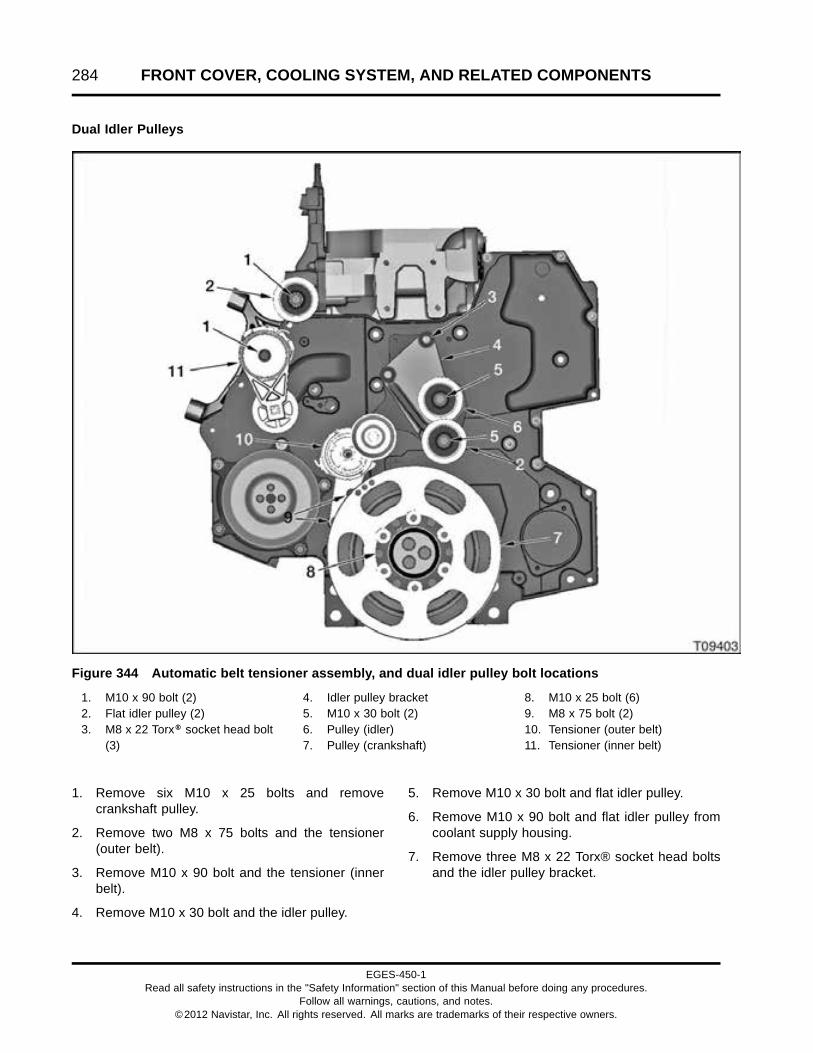
284 FRONT COVER, COOLING SYSTEM, AND RELATED COMPONENTS
Dual Idler Pulleys
Figure 344 Automatic belt tensioner assembly, and dual idler pulley bolt locations
1. M10 x 90 bolt (2)2. Flat idler pulley (2)3. M8 x 22 Torx® socket head bolt
(3)
4. Idler pulley bracket5. M10 x 30 bolt (2)6. Pulley (idler)7. Pulley (crankshaft)
8. M10 x 25 bolt (6)9. M8 x 75 bolt (2)10. Tensioner (outer belt)11. Tensioner (inner belt)
1. Remove six M10 x 25 bolts and removecrankshaft pulley.
2. Remove two M8 x 75 bolts and the tensioner(outer belt).
3. Remove M10 x 90 bolt and the tensioner (innerbelt).
4. Remove M10 x 30 bolt and the idler pulley.
5. Remove M10 x 30 bolt and flat idler pulley.
6. Remove M10 x 90 bolt and flat idler pulley fromcoolant supply housing.
7. Remove three M8 x 22 Torx® socket head boltsand the idler pulley bracket.
EGES-450-1Read all safety instructions in the "Safety Information" section of this Manual before doing any procedures.
Follow all warnings, cautions, and notes.©2012 Navistar, Inc. All rights reserved. All marks are trademarks of their respective owners.
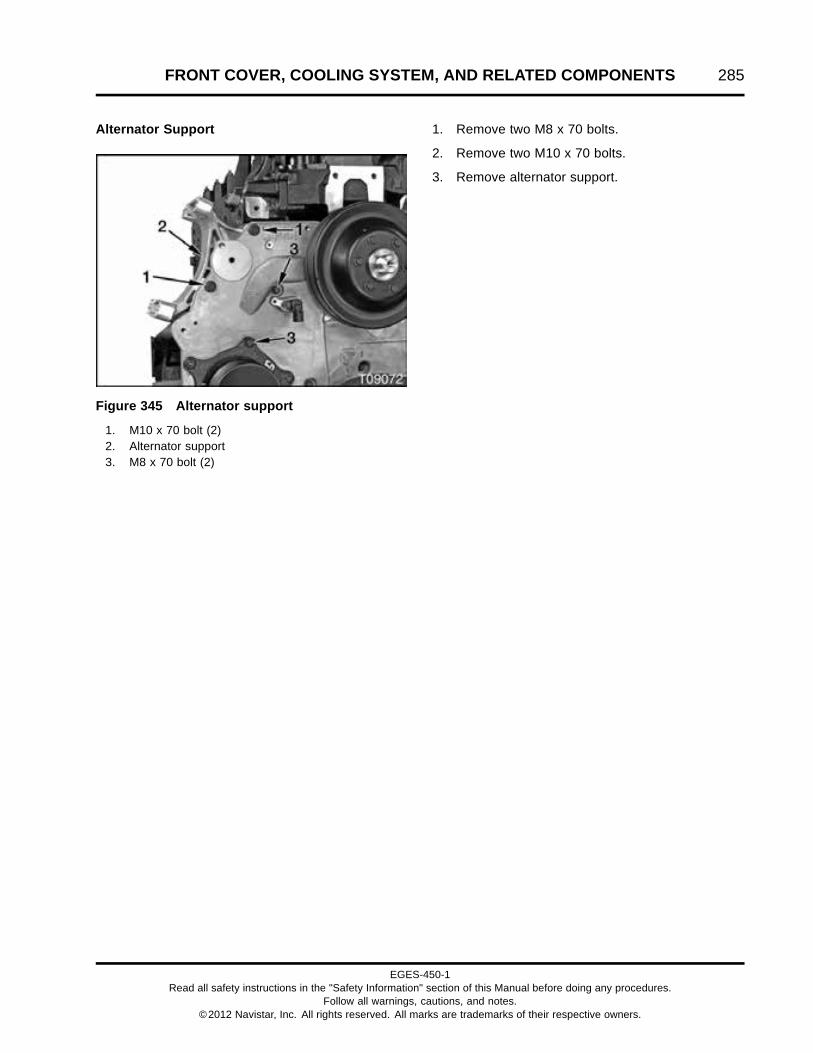
FRONT COVER, COOLING SYSTEM, AND RELATED COMPONENTS 285
Alternator Support
Figure 345 Alternator support
1. M10 x 70 bolt (2)2. Alternator support3. M8 x 70 bolt (2)
1. Remove two M8 x 70 bolts.
2. Remove two M10 x 70 bolts.
3. Remove alternator support.
EGES-450-1Read all safety instructions in the "Safety Information" section of this Manual before doing any procedures.
Follow all warnings, cautions, and notes.©2012 Navistar, Inc. All rights reserved. All marks are trademarks of their respective owners.

286 FRONT COVER, COOLING SYSTEM, AND RELATED COMPONENTS
Secondary Compressor Support, Flat IdlerPulleys, and Idler Support Plate
NOTE: The following procedure only applies toengines equipped with dual refrigerant compressoroption.
Figure 346 Dual refrigerant compressor support
1. M8 x 110 bolt (8)2. A/C (refrigerant) compressor (2)
3. Secondary refrigerantcompressor support
4. M10 x 30 bolt (2)
5. M10 x 60 bolt (2)6. Flat idler pulley assembly (2)7. Idler support plate
WARNING: To prevent personal injury ordeath, do not open pressurized refrigerant lines.
1. Remove four M8 x 110 bolts holding theouter refrigerant compressor to the secondaryrefrigerant compressor support.
2. Move outer refrigerant compressor out of the wayand secure with a strap or remove from engine.
3. If equipped, remove two M10 x 60 bolts andremove two flat idler pulley assemblies.
4. If equipped, remove two M10 x 30 bolts andremove the idler support plate from the secondaryrefrigerant compressor support.
5. Remove four M8 x 110 bolts holding thesecondary refrigerant compressor support andinner refrigerant compressor to the cylinder head.
EGES-450-1Read all safety instructions in the "Safety Information" section of this Manual before doing any procedures.
Follow all warnings, cautions, and notes.©2012 Navistar, Inc. All rights reserved. All marks are trademarks of their respective owners.

FRONT COVER, COOLING SYSTEM, AND RELATED COMPONENTS 287
Coolant Supply Housing (Refrigerant CompressorMount)
Figure 347 Coolant supply housing
1. Coolant supply housing (refrigerant compressormount)
2. M10 x 30 bolt (3)3. M10 x 45 bolt
1. Remove three M10 x 30 bolts.
2. Remove M10 x 45 bolt and remove coolant supplyhousing.
Figure 348 Coolant housing seal
3. Remove and discard coolant housing seal.
Water Outlet Tube and Thermostat
Figure 349 Water outlet tube and thermostat
1. Water outlet tube (typical)2. Thermostat assembly
NOTE: Water outlet tube configurations use eithertwo M8 x 25 bolts to hold the water outlet tube tothe cylinder head or two M8 x 120 bolts to hold thewater outlet tube and thermostat bypass housing tothe cylinder head.
1. Remove two M8 bolts holding the water outlettube to the cylinder head or thermostat bypasshousing.
2. Remove water outlet tube and thermostat.
3. If equipped, remove the thermostat bypasshousing and discard gasket.
EGES-450-1Read all safety instructions in the "Safety Information" section of this Manual before doing any procedures.
Follow all warnings, cautions, and notes.©2012 Navistar, Inc. All rights reserved. All marks are trademarks of their respective owners.

288 FRONT COVER, COOLING SYSTEM, AND RELATED COMPONENTS
Water Pump Assembly
Figure 350 Water pump and inlet elbow (typical)
1. M8 x 55 bolt (nut on front)2. M8 x 70 bolt3. Water pump pulley (typical)4. M8 x 16 bolt5. M6 x 12 bolt (4)6. M8 x 40 bolt (2)7. M8 x 30 stud bolt (3)8. Water inlet elbow
1. Remove four M6 x 12 bolts and remove waterpump pulley.
2. Remove M8 x 70 bolt.
3. Remove M8 x 55 bolt and nut (nut on front).
4. Remove M8 x 16 bolt.
5. Remove two M8 x 40 bolts.
6. Remove water pump assembly and discard waterpump housing seal.
Water Inlet Elbow
NOTE: Water inlet elbow configurations use eitherthree M8 stud bolts or three M8 x 30 bolts to hold thewater inlet elbow to the front cover.
1. Remove three M8 x 30 stud bolts holding thewater inlet elbow to the front cover.
2. Remove water inlet elbow and discard gasket.
EGES-450-1Read all safety instructions in the "Safety Information" section of this Manual before doing any procedures.
Follow all warnings, cautions, and notes.©2012 Navistar, Inc. All rights reserved. All marks are trademarks of their respective owners.

FRONT COVER, COOLING SYSTEM, AND RELATED COMPONENTS 289
Fan Drive
Spin-on Fan Drive
Figure 351 Fan drive pulley, spin-on
1. M8 x 20 bolt (6)2. Fan drive pulley
1. Remove six M8 x 20 bolts and remove the fandrive pulley.
Figure 352 Fan housing assembly, spin-on(typical)
1. M10 x 30 bolt (3)2. Fan housing assembly (typical)3. Fan pulley mounting hub
2. Remove three M8 x 30 bolts and remove the fanhousing assembly.
EGES-450-1Read all safety instructions in the "Safety Information" section of this Manual before doing any procedures.
Follow all warnings, cautions, and notes.©2012 Navistar, Inc. All rights reserved. All marks are trademarks of their respective owners.

290 FRONT COVER, COOLING SYSTEM, AND RELATED COMPONENTS
Horton DriveMaster® Fan Drive
Figure 353 Fan pulley, DriveMaster®
1. Fan mounting bracket (typical)2. Nut assembly3. Fan pulley
1. Remove nut assembly from fan mounting bracket,using a Fan Hub Wrench (2 inch) (page 327).
Figure 354 Fan mounting bracket, DriveMaster®(typical)
1. M10 x 30 bolt (3)2. Fan clutch air supply fitting (typical)3. Fan mounting bracket (typical)
NOTE: Fan drive configurations use either three orfour M10 x 30 bolts to hold the fan mounting bracketto the cylinder head.
2. Remove M10 x 30 bolts and remove the fanmounting bracket.
EGES-450-1Read all safety instructions in the "Safety Information" section of this Manual before doing any procedures.
Follow all warnings, cautions, and notes.©2012 Navistar, Inc. All rights reserved. All marks are trademarks of their respective owners.

FRONT COVER, COOLING SYSTEM, AND RELATED COMPONENTS 291
Vibration Damper, Hub, and Wear Sleeve
Vibration Damper—Single Drive Belt Engines
Figure 355 Vibration damper assembly
1. M10 x 16 bolt (6)2. M12 x 40 (12 point) damper bolt (3)3. Damper retainer4. Dowel pin
NOTE: The dowel pin for MaxxForce® 9 and 10vibration dampers is almost flush with the damperfront surface. The dowel pin for MaxxForce® DTvibration dampers protrudes out approximately 6 mm(0.24 in).
1. Remove six M10 x 16 bolts holding the vibrationdamper to the damper hub and remove vibrationdamper.
2. Remove three M12 x 40 (12 point) damper boltsand remove the damper retainer.
Vibration Damper—Dual Drive Belt Engines
Figure 356 Dual drive belt pulley and vibrationdamper
1. Pulley2. Dowel pin3. M10 x 25 bolt (6)4. Vibration damper5. M12 x 40 (12 point) damper bolt (3)6. Damper retainer
NOTE: The dowel pin for MaxxForce® 9 and 10vibration dampers is almost flush with the damperfront surface. The dowel pin for MaxxForce® DTvibration dampers protrudes out approximately 6 mm(0.24 in).
1. Remove six M10 x 25 bolts holding the pulley andvibration damper to the damper hub and removepulley and vibration damper.
2. Remove three M12 x 40 (12 point) damper boltsand remove the damper retainer.
EGES-450-1Read all safety instructions in the "Safety Information" section of this Manual before doing any procedures.
Follow all warnings, cautions, and notes.©2012 Navistar, Inc. All rights reserved. All marks are trademarks of their respective owners.

292 FRONT COVER, COOLING SYSTEM, AND RELATED COMPONENTS
Damper Hub
Figure 357 Damper hub and H-bar puller
1. Damper hub2. Crankshaft3. H-bar puller
1. Install two M10 x 80 bolts and washers throughH-bar puller (page 327) and into the damper hub.Adjust M10 x 80 bolts until the bolt heads are atequal lengths from the vibration damper mountingsurface.
2. Using hand tools only, tighten H-bar center shaftto pull damper hub off of crankshaft and removedamper hub.
Figure 358 Damper hub and wear sleeve
1. Muffler chisel2. Damper hub3. Wear sleeve
CAUTION: To prevent engine damage, do notdamage or distort damper hub while removing wearsleeve.
3. Carefully split wear sleeve with a muffler chisel(page 327) and remove sleeve from the damperhub. Be careful not to damage the damper hub.
EGES-450-1Read all safety instructions in the "Safety Information" section of this Manual before doing any procedures.
Follow all warnings, cautions, and notes.©2012 Navistar, Inc. All rights reserved. All marks are trademarks of their respective owners.

FRONT COVER, COOLING SYSTEM, AND RELATED COMPONENTS 293
Oil Pump Assembly
Figure 359 Oil pump housing assembly
1. Oil front seal2. M8 x 80 bolt and seal assembly3. M8 x 25 bolt (4)4. Dowel (2)5. M8 x 60 bolt (2)
NOTE: Be careful not to damage the crankshaft oroil front seal mounting surface while removing the oilfront seal.
1. Remove the oil front seal with a heel bar (page327) or seal puller, while the oil pump housingassembly is attached to the front cover.
2. Discard oil front seal.
3. Remove and discard M8 x 80 bolt and sealassembly.
4. Remove two M8 x 60 bolts holding the oil pumphousing to the front cover.
5. Remove four M8 x 25 bolts.
Figure 360 Oil pump housing assembly
1. Oil pump housing2. Inner rotor3. Outer rotor4. Oil pump seal (housing)
6. Remove the oil pump housing and discard oilpump (housing) seal.
CAUTION: To prevent engine damage, usepermanent marker to identify internal enginecomponents and their orientation. Do not use paintor temporary markers.
7. Mark inner and outer rotors with a permanentmarker, if oil pump is to be reused. Mark willindicate rotor turning direction and orientation tofront cover.
8. Remove outer rotor.
EGES-450-1Read all safety instructions in the "Safety Information" section of this Manual before doing any procedures.
Follow all warnings, cautions, and notes.©2012 Navistar, Inc. All rights reserved. All marks are trademarks of their respective owners.

294 FRONT COVER, COOLING SYSTEM, AND RELATED COMPONENTS
Figure 361 Vibration damper key, inner rotor,and oil pump housing plate
1. Washer seal2. Vibration damper key3. Inner rotor4. Oil pump housing plate
CAUTION: To prevent engine damage, do notdamage or distort the crankshaft keyway grooveduring vibration damper key removal or installation.
9. Carefully tap the vibration damper key out of thecrankshaft with a hammer and punch.
10. Remove washer seal and inner rotor fromcrankshaft.
11. Remove oil pump housing plate.
12. Remove oil pump seal (housing) from front coverand discard.
NOTE: To remove the oil pump spline drive, see OilPump Spline Drive and Crankshaft Gear (page 456).
Front Engine Mount
Figure 362 Front engine mount
1. M18 x 70 bolt, upper (2)2. M18 x 100 bolt, lower (2)
WARNING: To prevent personal injury ordeath, make sure the engine is supported beforeremoving mounting hardware.
1. Properly support the engine.
2. Remove two upper M18 x 70 bolts.
3. Support front engine mount and remove two lowerM18 x 100 bolts.
4. Remove front engine mounting bracket.
EGES-450-1Read all safety instructions in the "Safety Information" section of this Manual before doing any procedures.
Follow all warnings, cautions, and notes.©2012 Navistar, Inc. All rights reserved. All marks are trademarks of their respective owners.
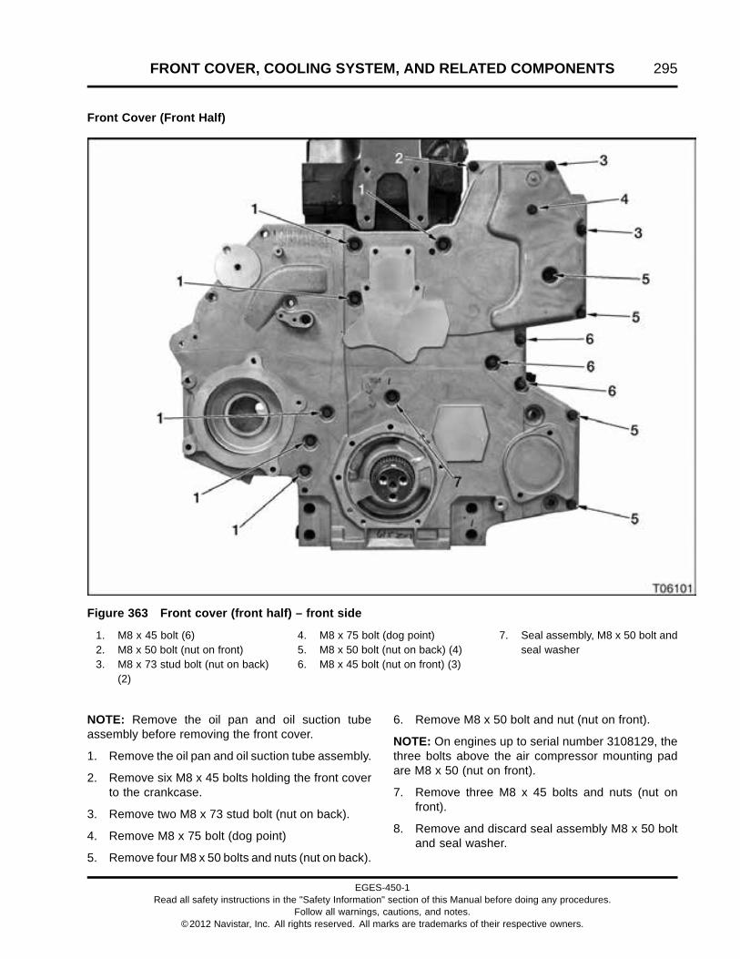
FRONT COVER, COOLING SYSTEM, AND RELATED COMPONENTS 295
Front Cover (Front Half)
Figure 363 Front cover (front half) – front side
1. M8 x 45 bolt (6)2. M8 x 50 bolt (nut on front)3. M8 x 73 stud bolt (nut on back)
(2)
4. M8 x 75 bolt (dog point)5. M8 x 50 bolt (nut on back) (4)6. M8 x 45 bolt (nut on front) (3)
7. Seal assembly, M8 x 50 bolt andseal washer
NOTE: Remove the oil pan and oil suction tubeassembly before removing the front cover.
1. Remove the oil pan and oil suction tube assembly.
2. Remove six M8 x 45 bolts holding the front coverto the crankcase.
3. Remove two M8 x 73 stud bolt (nut on back).
4. Remove M8 x 75 bolt (dog point)
5. Remove four M8 x 50 bolts and nuts (nut on back).
6. Remove M8 x 50 bolt and nut (nut on front).
NOTE: On engines up to serial number 3108129, thethree bolts above the air compressor mounting padare M8 x 50 (nut on front).
7. Remove three M8 x 45 bolts and nuts (nut onfront).
8. Remove and discard seal assembly M8 x 50 boltand seal washer.
EGES-450-1Read all safety instructions in the "Safety Information" section of this Manual before doing any procedures.
Follow all warnings, cautions, and notes.©2012 Navistar, Inc. All rights reserved. All marks are trademarks of their respective owners.

296 FRONT COVER, COOLING SYSTEM, AND RELATED COMPONENTS
9. Remove front cover (front half) by sliding coverforward and off two dowel pins.
10. Remove and discard oil and coolant gaskets andO-ring seals from the front cover (front half) – backside.
Idler Gears
NOTE: Measure lower idler, upper idler, and camshaftgear backlash (page 299) before removing any gearsfrom the gear train.
Figure 364 Gear train
1. Camshaft gear2. Camshaft to upper idler gear
timing marks (single dimple)3. Upper idler gear
4. M16 x 65 bolt (12 point)5. Upper idler to lower idler gear
timing marks (double dimple)6. Lower idler gear
7. M20 x 70 bolt8. Lower idler to crankshaft gear
timing marks9. Crankshaft gear
EGES-450-1Read all safety instructions in the "Safety Information" section of this Manual before doing any procedures.
Follow all warnings, cautions, and notes.©2012 Navistar, Inc. All rights reserved. All marks are trademarks of their respective owners.

FRONT COVER, COOLING SYSTEM, AND RELATED COMPONENTS 297
NOTE: Once timing marks are aligned, the crankshaftwill require 34 revolutions to align timing marks again.
1. Rotate crankshaft until camshaft, upper idler,lower idler, and crankshaft gears timing marksare aligned.
2. Remove M20 x 70 bolt using Lower Idler GearSocket (page 327) and a 3/4 inch drive breakerbar.
3. Remove lower idler gear.
4. Remove M16 x 65 bolt using a 16 mm 12 pointimpact socket (page 327) and a 1/2 inch drivebreaker bar.
5. Remove upper idler gear.
NOTE: If required, measure camshaft end play (page460) after removing the upper idler gear but beforeremoving camshaft gear.
EGES-450-1Read all safety instructions in the "Safety Information" section of this Manual before doing any procedures.
Follow all warnings, cautions, and notes.©2012 Navistar, Inc. All rights reserved. All marks are trademarks of their respective owners.

298 FRONT COVER, COOLING SYSTEM, AND RELATED COMPONENTS
Front Cover (Rear Half)
Figure 365 Front cover (rear half) – front side
1. Special M8 x 20 hex flange bolt(8)
2. Dowel pins (4)
1. Remove Camshaft Gear (page 451) or removeCamshaft Assembly (page 452).
2. Remove eight special M8 x 20 hex flange boltsholding the front cover (rear half) to the crankcase.
3. Pull cover outward to slide dowel pins out ofcrankcase and remove cover from engine.
4. Remove and discard oil and coolant gaskets fromthe front cover (rear half) – crankcase side.
EGES-450-1Read all safety instructions in the "Safety Information" section of this Manual before doing any procedures.
Follow all warnings, cautions, and notes.©2012 Navistar, Inc. All rights reserved. All marks are trademarks of their respective owners.

FRONT COVER, COOLING SYSTEM, AND RELATED COMPONENTS 299
Cleaning, Inspection, andMeasurement
WARNING: To prevent personal injury ordeath, wear safety glasses with side shields.Limit compressed air pressure to 207 kPa (30 psi).
Cleaning and Inspection
1. Clean coolant supply housing, water pump, waterinlet elbow, water outlet tube, oil pump housing,front engine mount, and front cover with a suitablenon-caustic solvent.
2. Blow parts dry using filtered compressed air.
3. Clean coolant and oil seal mating surfaces onthe cylinder head, coolant supply housing, waterpump, water inlet elbow, water outlet tube, oilpump housing, and front cover.
4. Inspect alternator support, secondary refrigerantcompressor support, coolant supply housing,water inlet elbow, vibration damper assembly, oilpump housing, oil pump inner and outer rotors,front cover, and idler gears for cracks, damage,or excessive wear. Replace parts if required.
5. Inspect drive belt for excessive cracks and wear.Replace if necessary.
6. Inspect belt tensioner to make sure tensioner armand pulley are properly in line with the fan drivebelt and not coming apart. Make sure tensionerarm is not binding and pulley bearing is not loose.Replace automatic belt tensioner assembly ifrequired.
7. Inspect thermostat and gasket. If thermostat isstuck open, damaged, cracked, or not openingproperly replace thermostat and gasket.
8. Inspect fan drive bearing by wiggling fan pulley. Ifbearing has excess play, replace fan housing ormounting bracket.
9. Inspect water pump. Wiggle water pump pulley.If water pump bearing has excess play, replacewater pump. Inspect water pump housing forcoolant leaks. Replace water pump if leaking.
Measuring Gear Backlash
NOTE: Remove rocker arm assembly to releasepressure exerted by valve train.
Lower Idler Gear Backlash
Figure 366 Lower idler gear and dial indicator
1. Lower idler gear2. Dial indicator3. Crankshaft gear
1. Mount a dial indicator set (page 327) on a levelengine surface.
2. Place dial indicator tip on one of the lower idlergear teeth. Position dial indicator tangent (90degrees relative to the plane of the gear tooth).
3. Rotate lower idler gear by hand in one direction,without moving the crankshaft gear, and zero thedial indicator.
4. Rock the lower idler gear back and forth withoutmoving the crankshaft gear. If lower idler gear tocrankshaft gear backlash exceeds Specifications(page 325), replace the lower idler gear.
EGES-450-1Read all safety instructions in the "Safety Information" section of this Manual before doing any procedures.
Follow all warnings, cautions, and notes.©2012 Navistar, Inc. All rights reserved. All marks are trademarks of their respective owners.

300 FRONT COVER, COOLING SYSTEM, AND RELATED COMPONENTS
Upper Idler Gear Backlash
Figure 367 Upper idler gear and dial indicator
1. Upper idler gear2. Dial indicator3. Lower idler gear
1. Mount a dial indicator set (page 327) on a levelengine surface.
2. Place dial indicator tip on one of the upper idlergear teeth. Position dial indicator tangent (90degrees relative to the plane of the gear tooth).
3. Rotate upper idler gear by hand in one directionwhile holding the lower idler gear stationary witha gear locking tool. Zero the dial indicator.
4. Rock the upper idler gear back and forth withoutmoving the lower idler gear. If upper idler gear tolower idler gear backlash exceeds Specifications(page 325), replace upper idler gear.
Camshaft Gear Backlash
Figure 368 Camshaft gear and dial indicator
1. Dial indicator2. Upper idler gear3. Camshaft gear
1. Mount a dial indicator set (page 327) on a levelengine surface.
2. Place dial indicator tip on one of the camshaft gearteeth. Position dial indicator tangent (90 degreesrelative to the plane of the gear tooth).
3. Rotate camshaft gear by hand in one directionwhile holding the upper idler gear stationary witha gear locking tool or screwdriver. Zero the dialindicator.
4. Rock the camshaft gear back and forth withoutmoving the upper idler gear. If camshaft gear toupper idler gear backlash exceeds Specifications(page 325), replace camshaft gear.
EGES-450-1Read all safety instructions in the "Safety Information" section of this Manual before doing any procedures.
Follow all warnings, cautions, and notes.©2012 Navistar, Inc. All rights reserved. All marks are trademarks of their respective owners.

FRONT COVER, COOLING SYSTEM, AND RELATED COMPONENTS 301
Measuring Oil Pump Side Clearance
Figure 369 Oil pump side clearancemeasurement
1. Feeler gauge2. Oil pump housing3. Outer rotor
1. Coat outer rotor with oil and install rotor in oil pumphousing.
2. Check oil pump side clearance Specification(page 325) and choose the appropriate thicknessfeeler gauge (page 327).
3. Insert feeler gauge between the oil pump housingand outer rotor.
4. Replace oil pump assembly if not withinspecification.
Measuring Oil Pump End Clearance
Figure 370 Oil pump end clearancemeasurement
1. Straightedge2. Feeler gauge3. Outer rotor4. Inner rotor
1. Place a straightedge (page 327) across the oilpump mounting surface.
2. Check oil pump end clearance Specification (page325) and choose the appropriate thickness feelergauge (page 327).
3. Slide feeler gauge between the straightedge andthe oil pump inner and outer rotors.
4. Replace oil pump and rotor assembly if not withinspecification.
EGES-450-1Read all safety instructions in the "Safety Information" section of this Manual before doing any procedures.
Follow all warnings, cautions, and notes.©2012 Navistar, Inc. All rights reserved. All marks are trademarks of their respective owners.
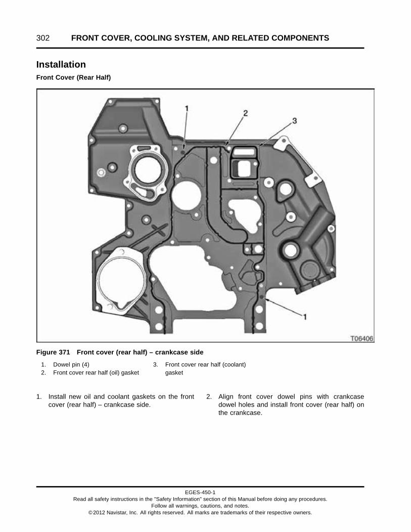
302 FRONT COVER, COOLING SYSTEM, AND RELATED COMPONENTS
InstallationFront Cover (Rear Half)
Figure 371 Front cover (rear half) – crankcase side
1. Dowel pin (4)2. Front cover rear half (oil) gasket
3. Front cover rear half (coolant)gasket
1. Install new oil and coolant gaskets on the frontcover (rear half) – crankcase side.
2. Align front cover dowel pins with crankcasedowel holes and install front cover (rear half) onthe crankcase.
EGES-450-1Read all safety instructions in the "Safety Information" section of this Manual before doing any procedures.
Follow all warnings, cautions, and notes.©2012 Navistar, Inc. All rights reserved. All marks are trademarks of their respective owners.

FRONT COVER, COOLING SYSTEM, AND RELATED COMPONENTS 303
Figure 372 Front cover (rear half) – front side
1. Special M8 x 20 hex flange bolt(8)
2. Dowel pins (4)
3. Install eight special M8 x 20 hex flange bolts fingertight.
4. Tighten eight special M8 x 20 hex flange bolts tostandard torque (page 523).
5. Install Camshaft Assembly (page 465) orCamshaft Gear (page 465).
EGES-450-1Read all safety instructions in the "Safety Information" section of this Manual before doing any procedures.
Follow all warnings, cautions, and notes.©2012 Navistar, Inc. All rights reserved. All marks are trademarks of their respective owners.

304 FRONT COVER, COOLING SYSTEM, AND RELATED COMPONENTS
Idler Gears
Figure 373 Gear train
1. Camshaft gear2. Camshaft to upper idler gear
timing marks (single dimple)3. Upper idler gear
4. M16 x 65 bolt (12 point)5. Upper idler to lower idler gear
timing marks (double dimple)6. Lower idler gear
7. M20 x 70 bolt8. Lower idler to crankshaft gear
timing marks (single dimple)9. Crankshaft gear
NOTE: Gear train gears should be assembled andinstalled with the timing marks facing out as shown.
1. Install upper idler gear on the crankcase and alignupper idler gear (single dimple) timing mark withcamshaft gear (single dimple) timing mark. Installupper idler gear M16 x 65 bolt finger tight.
2. Install lower idler gear on the crankcase and alignlower idler gear (single dimple) timing mark withcrankshaft gear timing mark and align lower idler
gear (double dimple) timing mark with upper idlergear (double dimple) timing mark. Install loweridler gear M20 x 70 bolt finger tight.
3. Tighten upper idler gear M16 x 65 bolt to specialtorque (page 326) using a 16 mm 12 point impactsocket (page 327).
4. Tighten lower idler gear M20 x 70 bolt to specialtorque (page 326) using Lower Idler Gear Socket(page 327).
EGES-450-1Read all safety instructions in the "Safety Information" section of this Manual before doing any procedures.
Follow all warnings, cautions, and notes.©2012 Navistar, Inc. All rights reserved. All marks are trademarks of their respective owners.

FRONT COVER, COOLING SYSTEM, AND RELATED COMPONENTS 305
NOTE: Once timing marks are aligned, the crankshaftwill require 34 revolutions to align timing marks again.
5. Measure lower idler, upper idler, and camshaftgears backlash (page 299).
6. Install the high-pressure oil pump and measuregear backlash between the upper idler gear
and the high-pressure oil pump gear. SeeSpecifications (page 325).
7. Measure high-pressure oil pump end play. SeeSpecifications (page 325).
EGES-450-1Read all safety instructions in the "Safety Information" section of this Manual before doing any procedures.
Follow all warnings, cautions, and notes.©2012 Navistar, Inc. All rights reserved. All marks are trademarks of their respective owners.

306 FRONT COVER, COOLING SYSTEM, AND RELATED COMPONENTS
Front Cover (Front Half)
Figure 374 Front cover (front half) – back side
1. O-ring (4)2. Dowel hole (2)
3. Front cover front half (oil) gasket 4. Front cover front half (coolant)gasket
1. Install a new oil gasket, coolant gasket, and fourO-rings to the front cover (front half) recesses.
2. Install the front cover (front half) on the front cover(rear half) and align front half dowel holes with rearhalf dowel pins.
EGES-450-1Read all safety instructions in the "Safety Information" section of this Manual before doing any procedures.
Follow all warnings, cautions, and notes.©2012 Navistar, Inc. All rights reserved. All marks are trademarks of their respective owners.
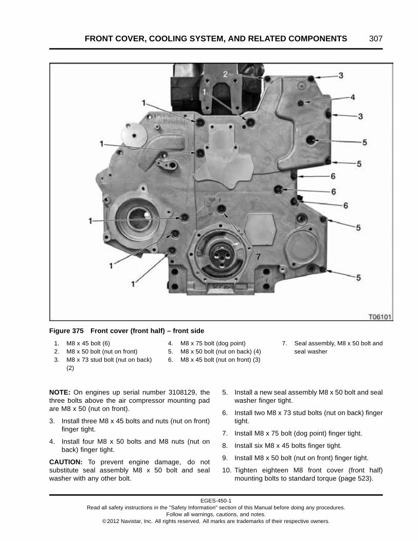
FRONT COVER, COOLING SYSTEM, AND RELATED COMPONENTS 307
Figure 375 Front cover (front half) – front side
1. M8 x 45 bolt (6)2. M8 x 50 bolt (nut on front)3. M8 x 73 stud bolt (nut on back)
(2)
4. M8 x 75 bolt (dog point)5. M8 x 50 bolt (nut on back) (4)6. M8 x 45 bolt (nut on front) (3)
7. Seal assembly, M8 x 50 bolt andseal washer
NOTE: On engines up serial number 3108129, thethree bolts above the air compressor mounting padare M8 x 50 (nut on front).
3. Install three M8 x 45 bolts and nuts (nut on front)finger tight.
4. Install four M8 x 50 bolts and M8 nuts (nut onback) finger tight.
CAUTION: To prevent engine damage, do notsubstitute seal assembly M8 x 50 bolt and sealwasher with any other bolt.
5. Install a new seal assembly M8 x 50 bolt and sealwasher finger tight.
6. Install two M8 x 73 stud bolts (nut on back) fingertight.
7. Install M8 x 75 bolt (dog point) finger tight.
8. Install six M8 x 45 bolts finger tight.
9. Install M8 x 50 bolt (nut on front) finger tight.
10. Tighten eighteen M8 front cover (front half)mounting bolts to standard torque (page 523).
EGES-450-1Read all safety instructions in the "Safety Information" section of this Manual before doing any procedures.
Follow all warnings, cautions, and notes.©2012 Navistar, Inc. All rights reserved. All marks are trademarks of their respective owners.

308 FRONT COVER, COOLING SYSTEM, AND RELATED COMPONENTS
Front Engine Mount
Figure 376 Front engine mount
1. M18 x 70 bolt, upper (2)2. M18 x 100 bolt, lower (2)
1. Position front engine mount on front cover andinstall two lower M18 x 100 bolts finger tight.
2. Install two upper M18 x 70 bolts finger tight.
3. Tighten two M18 x 100 and two M18 x 70 bolts tospecial torque (page 326).
Oil Pump Assembly
Figure 377 Oil pump housing plate and seal
1. Oil pump seal (housing plate)2. Oil pump housing plate
1. Lubricate a new oil pump seal (housing) with cleanengine oil and install in the front cover. Install theoil pump housing plate.
Figure 378 Vibration damper key, inner rotor,and washer seal
1. Washer seal2. Vibration damper key3. Inner rotor
CAUTION: To prevent engine damage, make sureused oil pump inner and outer rotors rotate in the samedirection as before removal. See marks added duringremoval for proper rotor orientation.
2. Slide oil pump inner rotor on the crankshaft oilpump spline drive.
3. Install washer seal with angled outer edgepointing out toward the front of the engine.
CAUTION: To prevent engine damage, do not mark ordistort the crankshaft keyway groove during vibrationdamper key installation.
4. Carefully tap the vibration damper key into thecrankshaft keyway groove with a hammer.
EGES-450-1Read all safety instructions in the "Safety Information" section of this Manual before doing any procedures.
Follow all warnings, cautions, and notes.©2012 Navistar, Inc. All rights reserved. All marks are trademarks of their respective owners.
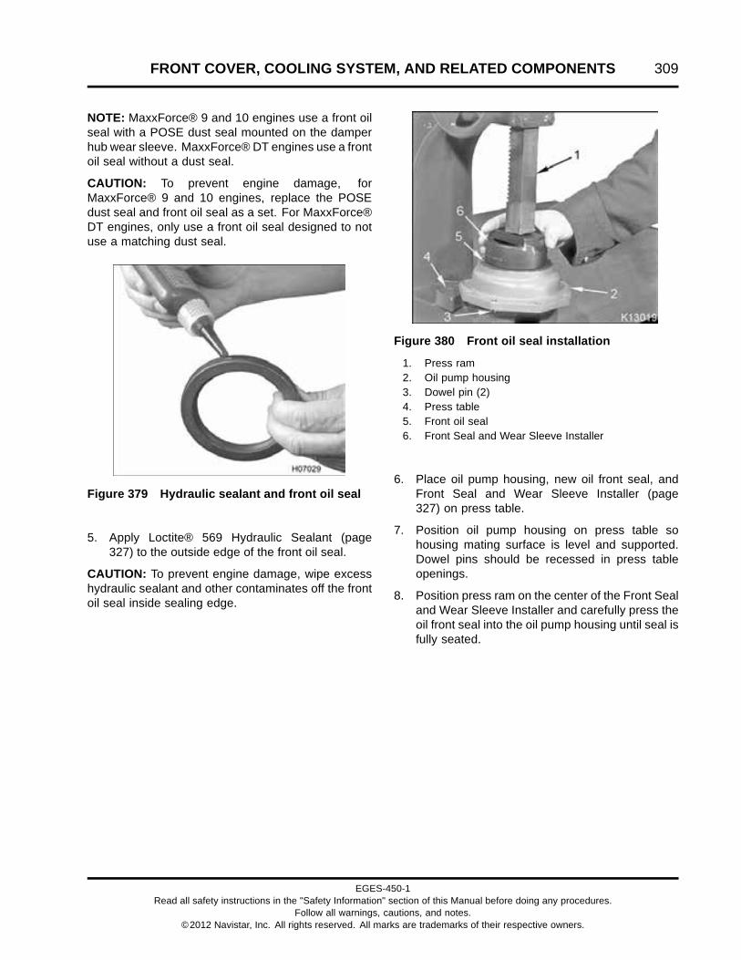
FRONT COVER, COOLING SYSTEM, AND RELATED COMPONENTS 309
NOTE: MaxxForce® 9 and 10 engines use a front oilseal with a POSE dust seal mounted on the damperhub wear sleeve. MaxxForce® DT engines use a frontoil seal without a dust seal.
CAUTION: To prevent engine damage, forMaxxForce® 9 and 10 engines, replace the POSEdust seal and front oil seal as a set. For MaxxForce®DT engines, only use a front oil seal designed to notuse a matching dust seal.
Figure 379 Hydraulic sealant and front oil seal
5. Apply Loctite® 569 Hydraulic Sealant (page327) to the outside edge of the front oil seal.
CAUTION: To prevent engine damage, wipe excesshydraulic sealant and other contaminates off the frontoil seal inside sealing edge.
Figure 380 Front oil seal installation
1. Press ram2. Oil pump housing3. Dowel pin (2)4. Press table5. Front oil seal6. Front Seal and Wear Sleeve Installer
6. Place oil pump housing, new oil front seal, andFront Seal and Wear Sleeve Installer (page327) on press table.
7. Position oil pump housing on press table sohousing mating surface is level and supported.Dowel pins should be recessed in press tableopenings.
8. Position press ram on the center of the Front Sealand Wear Sleeve Installer and carefully press theoil front seal into the oil pump housing until seal isfully seated.
EGES-450-1Read all safety instructions in the "Safety Information" section of this Manual before doing any procedures.
Follow all warnings, cautions, and notes.©2012 Navistar, Inc. All rights reserved. All marks are trademarks of their respective owners.
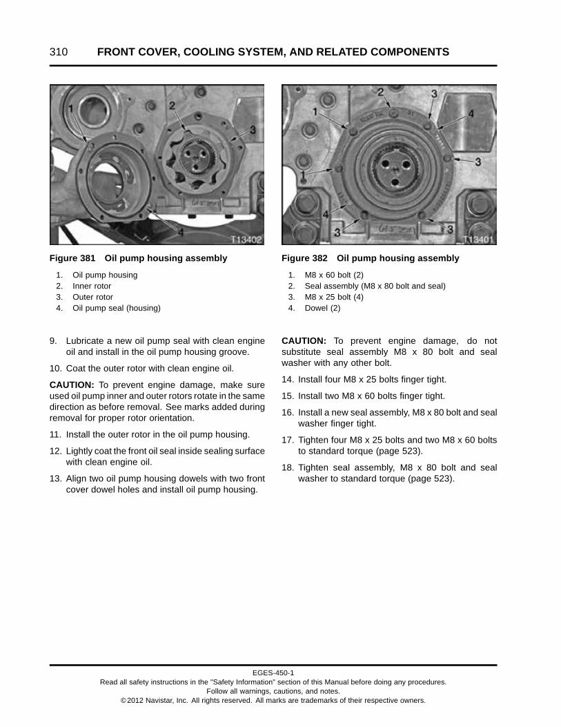
310 FRONT COVER, COOLING SYSTEM, AND RELATED COMPONENTS
Figure 381 Oil pump housing assembly
1. Oil pump housing2. Inner rotor3. Outer rotor4. Oil pump seal (housing)
9. Lubricate a new oil pump seal with clean engineoil and install in the oil pump housing groove.
10. Coat the outer rotor with clean engine oil.
CAUTION: To prevent engine damage, make sureused oil pump inner and outer rotors rotate in the samedirection as before removal. See marks added duringremoval for proper rotor orientation.
11. Install the outer rotor in the oil pump housing.
12. Lightly coat the front oil seal inside sealing surfacewith clean engine oil.
13. Align two oil pump housing dowels with two frontcover dowel holes and install oil pump housing.
Figure 382 Oil pump housing assembly
1. M8 x 60 bolt (2)2. Seal assembly (M8 x 80 bolt and seal)3. M8 x 25 bolt (4)4. Dowel (2)
CAUTION: To prevent engine damage, do notsubstitute seal assembly M8 x 80 bolt and sealwasher with any other bolt.
14. Install four M8 x 25 bolts finger tight.
15. Install two M8 x 60 bolts finger tight.
16. Install a new seal assembly, M8 x 80 bolt and sealwasher finger tight.
17. Tighten four M8 x 25 bolts and two M8 x 60 boltsto standard torque (page 523).
18. Tighten seal assembly, M8 x 80 bolt and sealwasher to standard torque (page 523).
EGES-450-1Read all safety instructions in the "Safety Information" section of this Manual before doing any procedures.
Follow all warnings, cautions, and notes.©2012 Navistar, Inc. All rights reserved. All marks are trademarks of their respective owners.

FRONT COVER, COOLING SYSTEM, AND RELATED COMPONENTS 311
Vibration Damper, Hub, and Wear Sleeve
Damper Hub
Figure 383 POSE seal (MaxxForce® 9 and 10only) and wear sleeve orientation
1. POSE seal (MaxxForce® 9 and 10 only)2. Wear sleeve3. Front of engine
NOTE: If service kit contains more than one wearsleeve, use sleeve that has the same width as thecurrent wear sleeve.
NOTE: MaxxForce® 9 and 10 engines have a POSEdust seal attached to the wear sleeve. A dust seal isnot used on MaxxForce® DT engines.
CAUTION: To prevent engine damage, forMaxxForce® 9 and 10 engines, replace the POSEdust seal and oil front seal as a set. For MaxxForce®DT engines, only use a oil front seal designed to notuse a matching dust seal.
NOTE: The chamfer (rounded edge) of the wearsleeve outside diameter must face in, toward theengine.
1. Apply Loctite® 569 Hydraulic Sealant (page327) to the inside diameter of a new wear sleeve.
Figure 384 Front seal and wear sleeveinstallation
1. Press ram2. Front Seal and Wear Sleeve Installer3. POSE dust seal (MaxxForce® 9 and 10 engines
only )4. Damper hub
2. Center the damper hub, new wear sleeve, andFront Seal and Wear Sleeve Installer (page327) under press ram.
3. Carefully press the new wear sleeve on thedamper hub until sleeve is fully seated.
4. Wipe any excess sealant off the outside diameterof the wear sleeve.
EGES-450-1Read all safety instructions in the "Safety Information" section of this Manual before doing any procedures.
Follow all warnings, cautions, and notes.©2012 Navistar, Inc. All rights reserved. All marks are trademarks of their respective owners.

312 FRONT COVER, COOLING SYSTEM, AND RELATED COMPONENTS
5. Mark damper hub with 100 °C (212 °F)Thermo-melt crayon (page 327).
Figure 385 Damper hub and hot plate
CAUTION: To prevent engine damage, do not heatdamper hub assembly above 100 °C (212 °F).
6. Heat damper hub on a hot plate (page 327), orother controlled heat source, until Thermo-meltcrayon mark melts.
Figure 386 Damper hub installation (typical)
WARNING: To prevent personal injury ordeath, wear heat insulated gloves when handlingheated components.
7. Install damper hub on crankshaft while wearingheat insulated gloves (page 327). Make surekeyway groove on damper hub aligns with keywayin crankshaft.
EGES-450-1Read all safety instructions in the "Safety Information" section of this Manual before doing any procedures.
Follow all warnings, cautions, and notes.©2012 Navistar, Inc. All rights reserved. All marks are trademarks of their respective owners.

FRONT COVER, COOLING SYSTEM, AND RELATED COMPONENTS 313
Figure 387 Damper hub
1. Dowel pin2. Damper retainer3. M12 x 40 (12 point) damper bolt (3)
WARNING: To prevent personal injury ordeath, damper hub must be completely seated onthe crankshaft.
CAUTION: To prevent engine damage, only use 15.2mm (0.60 in) thick damper retainer and Class 12.9damper bolts.
8. Install damper retainer and three M12 x 40damper bolts. Verify damper retainer is 15.2 mm(0.60 in) thick and damper bolts are Class 12.9.
9. Tighten three M12 x 40 damper bolts to specialtorque (page 326).
10. Retighten three M12 x 40 damper bolts to specialtorque (page 326) several times until each bolthas no movement.
Vibration Damper—Dual Drive Belt Engines
Figure 388 Dual drive belt pulley and vibrationdamper
1. Pulley (crankshaft)2. Dowel pin3. M10 x 25 bolt (6)4. Vibration damper5. M12 x 40 (12 point) damper bolt (3)6. Damper retainer
NOTE: The dowel pin for MaxxForce® 9 and 10vibration dampers is almost flush with the damperfront surface. The dowel pin for MaxxForce® DTvibration dampers protrudes out approximately 6 mm(0.24 in).
1. Install pulley and vibration damper assembly ondamper hub and align dowel holes with dowel pinon damper hub.
2. Install six M10 x 25 bolts finger tight.
3. Tighten six M10 x 25 bolts to special torque (page326).
EGES-450-1Read all safety instructions in the "Safety Information" section of this Manual before doing any procedures.
Follow all warnings, cautions, and notes.©2012 Navistar, Inc. All rights reserved. All marks are trademarks of their respective owners.

314 FRONT COVER, COOLING SYSTEM, AND RELATED COMPONENTS
Vibration Damper—Single Drive Belt Engines
Figure 389 Vibration damper assembly
1. M10 x 16 bolt (6)2. M12 x 40 (12 point) damper bolt (3)3. Damper retainer4. Dowel pin
CAUTION: To prevent engine damage, verify damperhub dowel pin is aligned with dowel hole of thevibration damper assembly.
1. Install vibration damper assembly on damper huband align dowel hole in damper with dowel pin ondamper hub.
2. Install six M10 x 16 bolts finger tight.
3. Tighten six M10 x 16 bolts to special torque (page326).
Fan Drive
Spin-on Fan Drive
Figure 390 Fan housing assembly, spin-on(typical)
1. M10 x 30 bolt (3)2. Fan housing assembly (typical)3. Fan pulley mounting hub
1. Install fan housing assembly on cylinder head andinstall three M10 x 30 bolts finger tight.
2. Tighten bolts to standard torque (page 523).
EGES-450-1Read all safety instructions in the "Safety Information" section of this Manual before doing any procedures.
Follow all warnings, cautions, and notes.©2012 Navistar, Inc. All rights reserved. All marks are trademarks of their respective owners.

FRONT COVER, COOLING SYSTEM, AND RELATED COMPONENTS 315
Figure 391 Fan drive pulley, spin-on
1. M8 x 20 bolt (6)2. Fan drive pulley
3. Install fan drive pulley on fan housing assemblyand install six M8 x 20 bolts finger tight.
Figure 392 Fan Wrench and fan drive pulley
4. Hold the fan drive pulley stationary with a FanWrench (for spin-on fan pulley) (page 327).
5. Tighten six M8 x 20 bolts to standard torque (page523).
EGES-450-1Read all safety instructions in the "Safety Information" section of this Manual before doing any procedures.
Follow all warnings, cautions, and notes.©2012 Navistar, Inc. All rights reserved. All marks are trademarks of their respective owners.

316 FRONT COVER, COOLING SYSTEM, AND RELATED COMPONENTS
Horton DriveMaster® Fan Drive
Figure 393 Fan mounting bracket, DriveMaster®(typical)
1. M10 x 30 bolt (3)2. Fan clutch air supply fitting (typical)3. Fan mounting bracket (typical)
NOTE: Fan drive configurations use either three orfour M10 x 30 bolts to hold the fan mounting bracketto the cylinder head.
1. Install fan mounting bracket to the cylinder headand secure with M10 x 30 bolts.
2. Tighten M10 x 30 bolts to standard torque (page523).
Figure 394 Fan pulley, DriveMaster®
1. Fan mounting bracket (typical)2. Nut assembly3. Fan Pulley
3. Slide fan pulley on fan mounting bracket.
CAUTION: To prevent engine damage, install nutassembly with collar toward engine.
4. Install nut assembly (collar toward engine) on thefan mounting bracket and finger tighten.
5. Tighten nut assembly to special torque (page326) using a Fan Hub Wrench (2 inch) (page327) and a torque wrench. See Using a TorqueWrench Extension (page 524) to calculate thecorrect torque wrench setting.
EGES-450-1Read all safety instructions in the "Safety Information" section of this Manual before doing any procedures.
Follow all warnings, cautions, and notes.©2012 Navistar, Inc. All rights reserved. All marks are trademarks of their respective owners.

FRONT COVER, COOLING SYSTEM, AND RELATED COMPONENTS 317
Water Outlet Tube, and Thermostat
Figure 395 Water outlet tube and thermostat
1. Water outlet tube (typical)2. Thermostat assembly
1. If equipped with a thermostat bypass, install a newthermostat seal and then install the thermostatbypass housing on the cylinder head.
2. Install thermostat assembly in the cylinder heador thermostat bypass.
NOTE: Water outlet tube configurations use eithertwo M8 x 25 bolts to hold the water outlet tube tothe cylinder head or two M8 x 120 bolts to hold thewater outlet tube and thermostat bypass housing tothe cylinder head.
3. Install water outlet tube and finger tighten two M8bolts.
4. Tighten two M8 bolts to standard torque (page523).
Water Pump Assembly
Figure 396 Water pump and inlet elbow
1. M8 x 55 bolt (nut on front)2. M8 x 70 bolt3. Water pump pulley (typical)4. M8 x 16 bolt5. M6 x 12 bolt (4)6. M8 x 40 bolt (2)7. M8 x 30 stud bolt (3)8. Water inlet elbow
1. Install a new water pump seal in the water pumpassembly.
2. Install water pump assembly on the front coverand install two M8 x 40 bolts.
NOTE: Do not install the M8 x 70 bolt at this time if thealternator bracket was removed.
3. Install M8 x 70 bolt, M8 x 55 bolt (nut on front),and M8 x 16 bolt finger tight.
4. Tighten five M8 water pump bolts to standardtorque (page 523).
5. Install the water pump pulley on the water pumpand install four M6 x 12 pulley bolts finger tight.
6. Tighten four M6 x 12 pulley bolts to standardtorque (page 523).
EGES-450-1Read all safety instructions in the "Safety Information" section of this Manual before doing any procedures.
Follow all warnings, cautions, and notes.©2012 Navistar, Inc. All rights reserved. All marks are trademarks of their respective owners.

318 FRONT COVER, COOLING SYSTEM, AND RELATED COMPONENTS
Water Inlet Elbow
NOTE: Water inlet elbow configurations use eitherthree M8 stud bolts or three M8 x 30 bolts to hold thewater inlet elbow to the front cover.
1. Install a new water inlet elbow gasket into frontcover.
2. Install water inlet elbow using three M8 x 30 waterinlet elbow stud bolts finger tight.
3. Tighten three M8 x 30 stud bolts to standardtorque (page 523).
Coolant Housing (Refrigerant CompressorMount)
Figure 397 Coolant housing seal
1. Install a new coolant housing seal in the coolanthousing.
Figure 398 Coolant supply housing
1. Coolant housing (refrigerant compressor mount)2. M10 x 30 bolt (3)3. M10 x 45 bolt
2. Install coolant supply housing on the cylinderhead and install three M10 x 30 bolts finger tight.
3. Install M10 x 45 bolt finger tight.
4. Tighten three M10 x 30 bolts and M10 x 45 bolt tostandard torque (page 523).
EGES-450-1Read all safety instructions in the "Safety Information" section of this Manual before doing any procedures.
Follow all warnings, cautions, and notes.©2012 Navistar, Inc. All rights reserved. All marks are trademarks of their respective owners.

FRONT COVER, COOLING SYSTEM, AND RELATED COMPONENTS 319
Alternator Support
Figure 399 Alternator support
1. M10 x 70 bolt (2)2. Alternator support3. M8 x 70 bolt (2)
1. Position alternator support on the back of the frontcover.
2. Install two M10 x 70 bolts through the front coverand alternator support.
3. Install two M8 x 70 bolts through the front coverand alternator support.
4. Tighten two M10 x 70 bolts and two M8 x 70 boltto standard torque (page 523).
EGES-450-1Read all safety instructions in the "Safety Information" section of this Manual before doing any procedures.
Follow all warnings, cautions, and notes.©2012 Navistar, Inc. All rights reserved. All marks are trademarks of their respective owners.

320 FRONT COVER, COOLING SYSTEM, AND RELATED COMPONENTS
Dual Idler Pulleys
Figure 400 Belt tensioner, and dual idler pulley bolt locations
1. M10 x 90 bolt (2)2. Flat idler pulley (2)3. M8 x 22 Torx® socket head bolt
(3)
4. Idler pulley bracket5. M10 x 30 bolt (2)6. Pulley (idler)7. Pulley (crankshaft)
8. M10 x 25 bolt (6)9. M8 x 75 bolt (2)10. Tensioner (outer belt)11. Tensioner (inner belt)
1. Install the idler pulley bracket and the three M8 x22 Torx® socket head bolts and tighten bolts tostandard torque (page 523).
2. Install the flat idler pulley and the M10 x 90 bolton the coolant supply housing and tighten bolt tostandard torque (page 523).
3. Install the flat idler pulley and the M10 x 30 boltand tighten bolt to standard torque (page 523).
4. Install the pulley (idler) and the M10 x 30 bolt andtighten bolt to standard torque (page 523).
5. Install the tensioner (inner belt) and the M10 x90 bolt and tighten bolt to standard torque (page523).
6. Install the tensioner (outer belt) and the two M8 x75 bolts and tighten bolts to standard torque (page523).
EGES-450-1Read all safety instructions in the "Safety Information" section of this Manual before doing any procedures.
Follow all warnings, cautions, and notes.©2012 Navistar, Inc. All rights reserved. All marks are trademarks of their respective owners.

FRONT COVER, COOLING SYSTEM, AND RELATED COMPONENTS 321
7. Install the pulley and the six M10 x 25 bolts andtighten bolts to special torque (page 326).
Secondary Compressor Support, Flat IdlerPulleys, and Idler Support Plate
NOTE: The following procedure only appliesto engines equipped with dual A/C (refrigerant)compressor option.
Figure 401 Dual refrigerant compressor support
1. M8 x 110 bolt (8)2. A/C (refrigerant) compressor (2)
3. Secondary refrigerantcompressor support
4. M10 x 30 bolt (2)
5. M10 x 60 bolt (2)6. Flat idler pulley assembly (2)7. Idler support plate
EGES-450-1Read all safety instructions in the "Safety Information" section of this Manual before doing any procedures.
Follow all warnings, cautions, and notes.©2012 Navistar, Inc. All rights reserved. All marks are trademarks of their respective owners.

322 FRONT COVER, COOLING SYSTEM, AND RELATED COMPONENTS
WARNING: To prevent personal injury ordeath, do not open pressurized refrigerant lines.
1. Position inner refrigerant compressor on thecoolant supply housing (refrigerant compressormount).
2. Install the secondary refrigerant compressorsupport and four M8 x 110 bolts.
3. Tighten four M8 x 110 bolts to standard torque(page 523).
4. Install the idler support plate and two M10 x 30bolts on the secondary refrigerant compressorsupport.
5. Tighten two M10 x 30 bolts to standard torque(page 523).
6. Install two flat idler pulley assemblies on the idlersupport plate and tighten two M10 x 60 bolts tostandard torque (page 523).
7. Install outer refrigerant compressor and four M8 x110 bolts.
8. Tighten four M8 x 110 bolts to standard torque(page 523).
EGES-450-1Read all safety instructions in the "Safety Information" section of this Manual before doing any procedures.
Follow all warnings, cautions, and notes.©2012 Navistar, Inc. All rights reserved. All marks are trademarks of their respective owners.

FRONT COVER, COOLING SYSTEM, AND RELATED COMPONENTS 323
Single Drive Belt
Figure 402 Single drive belt routing
1. Single refrigerant compressorand single idler pulley
2. Without refrigerant compressor 3. Dual refrigerant compressorsand dual idler pulleys
1. Install drive belt on all engine pulleys, except one.
2. Insert 1/2 inch square drive ratchet or breakerbar into automatic belt tensioner assembly squarehole.
3. Rotate tensioner (belt) clockwise.
4. Fit drive belt on last pulley and slowly releaseautomatic belt tensioner assembly.
5. Inspect each pulley to verify drive belt is properlyseated.
EGES-450-1Read all safety instructions in the "Safety Information" section of this Manual before doing any procedures.
Follow all warnings, cautions, and notes.©2012 Navistar, Inc. All rights reserved. All marks are trademarks of their respective owners.

324 FRONT COVER, COOLING SYSTEM, AND RELATED COMPONENTS
Dual Drive Belt
Figure 403 Dual drive belt routing
1. Inner drive belt2. Outer drive belt
1. Install inner drive belt on all engine pulleys, exceptone.
2. Insert 1/2 inch square drive ratchet or breaker barinto tensioner (inner belt) square hole.
3. Rotate automatic tensioner (inner belt) clockwise.
4. Fit inner drive belt on last pulley and slowlyrelease tensioner (inner belt).
5. Inspect each pulley to verify drive belt is properlyseated.
6. Install outer drive belt on all pulleys, except flatidler pulley.
7. Rotate tensioner (outer belt) counter clockwise,using a 16 mm socket and a ratchet or breakerbar.
8. Fit outer belt on flat idler pulley and slowly releasetensioner (outer belt).
9. Inspect each pulley to verify drive belt is properlyseated.
EGES-450-1Read all safety instructions in the "Safety Information" section of this Manual before doing any procedures.
Follow all warnings, cautions, and notes.©2012 Navistar, Inc. All rights reserved. All marks are trademarks of their respective owners.

FRONT COVER, COOLING SYSTEM, AND RELATED COMPONENTS 325
Specifications
Camshaft gear to upper idler gear maximum backlash 0.312 mm (0.012 in)
High-pressure oil pump end play 0.127 to 0.457 mm (0.005 to 0.018 in)
Lower idler gear to air compressor gear maximumbacklash
0.310 mm (0.012 in)
Lower idler gear to crankshaft gear maximumbacklash
0.338 mm (0.013 in)
Oil pump end clearance 0.05 to 0.13 mm (0.002 to 0.005 in)
Oil pump side clearance 0.48 to 0.62 mm (0.019 to 0.024 in)
Upper idler gear to high-pressure oil pump gearmaximum backlash
0.342 mm (0.013 in)
Upper idler gear to lower idler gear maximumbacklash
0.310 mm (0.012 in)
Vibration damper face runout (maximum) 1.52 mm (0.060 in)
Water Pump Pulley Diameters and Spin Ratios
Engine Pulley Diameter Spin Ratio
MaxxForce® DT 215 – 230 BHP 15.54 cm (6.12 in) 1.40: 1
MaxxForce® DT 245 – 260 BHP 13.93 cm (5.48 in) 1.55: 1
MaxxForce® DT 270 – 300 BHP 13.93 cm (5.48 in) 1.55: 1
MaxxForce® 9 and 10 12.54 cm (4.94 in) 1.73: 1
Fan Drive Configurations Diameters and Ratios (Spin-on)
Fan Center Line (CL)
Fan DriveConfiguration
Engine Verticalabove Crank
Lateral Offset(toward turbo)
PulleyDiameter
Fan DriveRatio
Spin-on 11” fancenter
MaxxForce®DT
279.4 mm(11 in)
none 200.66 mm(7.9 in)
1.08 : 1
Spin-on 13” fancenter
MaxxForce®DT
330.2 mm(13 in)
25.4 mm(1 in)
201.2 mm(7.92 in)
1.08 : 1
Spin-on 14.3” fancenter
MaxxForce®DT
363.22 mm(14.3 in)
none 218.95 mm(8.62 in)
0.99 : 1
Spin-on 14.3” fancenter
MaxxForce®DT
363.22 mm(14.3 in)
none 200.66 mm(7.9 in)
1.08 : 1
Spin-on 16.2” fancenter
MaxxForce®DT
411.5 mm(16.2 in)
95.3 mm(3.75 in)
219.5 mm(8.64 in)
0.99 : 1
Spin-on 16.2” fancenter
MaxxForce®DT
411.5 mm(16.2 in)
95.3 mm(3.75 in)
201.2 mm(7.92 in)
1.08 : 1
Spin-on 20” fancenter
MaxxForce®DT
508 mm(20 in)
none 21.95 cm(8.64 in)
0.99 : 1
EGES-450-1Read all safety instructions in the "Safety Information" section of this Manual before doing any procedures.
Follow all warnings, cautions, and notes.©2012 Navistar, Inc. All rights reserved. All marks are trademarks of their respective owners.

326 FRONT COVER, COOLING SYSTEM, AND RELATED COMPONENTS
Fan Drive Configurations Diameters and Ratios (DriveMaster®) — Single Drive Belt
Fan Center Line (CL)
Fan DriveConfiguration
Engine Vertical aboveCrank
Lateral Offset(toward turbo)
PulleyDiameter
Fan DriveRatio
Horton DriveMaster®11” fan center
MaxxForce®DT
279.4 mm(11 in)
none 200.66 mm(7.9 in)
1.08 : 1
Horton DriveMaster®13” fan center
MaxxForce®DT
330.2 mm(13 in)
25.4 mm(1 in)
20.12 cm(7.92 in)
1.08 : 1
Horton DriveMaster®14.3” fan center
MaxxForce®DT
363.22 mm(14.3 in)
none 218.95 mm(8.62 in)
0.99 : 1
Horton DriveMaster®16.2” fan center
MaxxForce®DT
411.5 mm(16.2 in)
95.3 mm(3.75 in)
20.12 cm(7.92 in)
1.08 : 1
Horton DriveMaster®20” fan center
MaxxForce®DT
508 mm(20 in)
none 21.95 cm(8.64 in)
0.99 : 1
Fan Drive Configurations Diameters and Ratios (DriveMaster®) — Dual Drive Belt
Fan Center Line (CL)
Fan DriveConfiguration
Engine Vertical aboveCrank
Lateral Offset(toward turbo)
PulleyDiameter
Fan DriveRatio
Horton DriveMaster®14.3” fan center
MaxxForce®DT
363.22 mm(14.3 in)
none 200.66 mm(7.9 in)
1.08 : 1
Horton DriveMaster®14.3” fan center
MaxxForce® 9and 10
508 mm(20 in)
none 18.14 cm(7.14 in)
1.2 : 1
Horton DriveMaster®20” fan center
MaxxForce®DT
508 mm(20 in)
none 20.12 cm(7.92 in)
1.08 : 1
Horton DriveMaster®20” fan center
MaxxForce® 9and 10
508 mm(20 in)
none 18.14 cm(7.14 in)
1.2 : 1
Special Torque
Damper (hub) bolts, M12 x 40 135 N·m (99 lbf·ft) Re-torque all bolts untilno movement
Front engine mount M18 bolts 368 N·m (271 lbf·ft)
Horton DriveMaster® nut assembly (2 inch) 177 N·m (130 lbf·ft)
Lower idler gear M20 x 70 bolt 639 N·m (470 lbf·ft)
PTO adapter cover, M10 x 25 bolts (PTO equipped enginesonly) 61 N·m (45 lbf·ft)
Upper idler gear M16 x 65 bolt 326 N·m (240 lbf·ft)
Vibration damper assembly M10 x 16 bolts 58 N·m (43 lbf·ft)
Vibration damper and pulley assembly M10 x 25 bolts 61 N·m (45 lbf·ft)
EGES-450-1Read all safety instructions in the "Safety Information" section of this Manual before doing any procedures.
Follow all warnings, cautions, and notes.©2012 Navistar, Inc. All rights reserved. All marks are trademarks of their respective owners.

FRONT COVER, COOLING SYSTEM, AND RELATED COMPONENTS 327
Special Service Tools
Dial indicator set Obtain locally
Fan Wrench (for spin-on fan pulley) ZTSE43971
Fan Hub Wrench, 2 inch (for DriveMaster® nut assembly) ZTSE43972
Feeler gauge Obtain locally
Front Seal and Wear Sleeve Installer ZTSE3004B
H-bar puller Obtain locally
Heat insulated gloves Obtain locally
Heel bar Obtain locally
Hot plate Obtain locally
Loctite® 569 Hydraulic Sealant Obtain locally
Lower Idler Gear Socket ZTSE4383
Muffler chisel Obtain locally
Straightedge Obtain locally
Thermo-melt crayon, 100 °C (212 °F) Obtain locally
16 mm 12 point impact socket Obtain locally
EGES-450-1Read all safety instructions in the "Safety Information" section of this Manual before doing any procedures.
Follow all warnings, cautions, and notes.©2012 Navistar, Inc. All rights reserved. All marks are trademarks of their respective owners.

328 FRONT COVER, COOLING SYSTEM, AND RELATED COMPONENTS
EGES-450-1Read all safety instructions in the "Safety Information" section of this Manual before doing any procedures.
Follow all warnings, cautions, and notes.©2012 Navistar, Inc. All rights reserved. All marks are trademarks of their respective owners.

CYLINDER HEAD AND VALVE TRAIN 329
Table of Contents
Illustrations and Description. . . . . . . . . . . . . . . . . . . . . . . . . . . . . . . . . . . . . . . . . . . . . . . . . . . . . . . . . . . . . . . . . . . . . . . . . . . . . . . . . . . . . . . . .331Exploded View of Cylinder Head and Valve Train Components. . . . . . . . . . . . . . . . . . . . . . . . . . . . . . . . . . . . . .331Description. . . . . . . . . . . . . . . . . . . . . . . . . . . . . . . . . . . . . . . . . . . . . . . . . . . . . . . . . . . . . . . . . . . . . . . . . . . . . . . . . . . . . . . . . . . . . . . . . . . .332
Periodic Service. . . . . . . . . . . . . . . . . . . . . . . . . . . . . . . . . . . . . . . . . . . . . . . . . . . . . . . . . . . . . . . . . . . . . . . . . . . . . . . . . . . . . . . . . . . . . . . . . . . . . . . .333Valve Lash Adjustment. . . . . . . . . . . . . . . . . . . . . . . . . . . . . . . . . . . . . . . . . . . . . . . . . . . . . . . . . . . . . . . . . . . . . . . . . . . . . . . . . . . . . .333
Removal. . . . . . . . . . . . . . . . . . . . . . . . . . . . . . . . . . . . . . . . . . . . . . . . . . . . . . . . . . . . . . . . . . . . . . . . . . . . . . . . . . . . . . . . . . . . . . . . . . . . . . . . . . . . . . . . .336Valve Cover. . . . . . . . . . . . . . . . . . . . . . . . . . . . . . . . . . . . . . . . . . . . . . . . . . . . . . . . . . . . . . . . . . . . . . . . . . . . . . . . . . . . . . . . . . . . . . . . . . . .336Rocker Arm Assembly. . . . . . . . . . . . . . . . . . . . . . . . . . . . . . . . . . . . . . . . . . . . . . . . . . . . . . . . . . . . . . . . . . . . . . . . . . . . . . . . . . . . . . .338Rocker Arms. . . . . . . . . . . . . . . . . . . . . . . . . . . . . . . . . . . . . . . . . . . . . . . . . . . . . . . . . . . . . . . . . . . . . . . . . . . . . . . . . . . . . . . . . . . . . . . . . .339Cylinder Head. . . . . . . . . . . . . . . . . . . . . . . . . . . . . . . . . . . . . . . . . . . . . . . . . . . . . . . . . . . . . . . . . . . . . . . . . . . . . . . . . . . . . . . . . . . . . . . . .339Roller Tappets and Guides. . . . . . . . . . . . . . . . . . . . . . . . . . . . . . . . . . . . . . . . . . . . . . . . . . . . . . . . . . . . . . . . . . . . . . . . . . . . . . . . . .340
Cleaning, Inspection, Measurement, and Testing. . . . . . . . . . . . . . . . . . . . . . . . . . . . . . . . . . . . . . . . . . . . . . . . . . . . . . . . . . . . . . . .341Measuring Camshaft Lobe Lift. . . . . . . . . . . . . . . . . . . . . . . . . . . . . . . . . . . . . . . . . . . . . . . . . . . . . . . . . . . . . . . . . . . . . . . . . . . . .341Cylinder Head Cleaning. . . . . . . . . . . . . . . . . . . . . . . . . . . . . . . . . . . . . . . . . . . . . . . . . . . . . . . . . . . . . . . . . . . . . . . . . . . . . . . . . . . . .341Cleaning and Inspection of Roller Tappets and Guides. . . . . . . . . . . . . . . . . . . . . . . . . . . . . . . . . . . . . . . . . . . . . . .342Cleaning and Inspection of Push Rods. . . . . . . . . . . . . . . . . . . . . . . . . . . . . . . . . . . . . . . . . . . . . . . . . . . . . . . . . . . . . . . . . .342Measuring Rocker Shaft. . . . . . . . . . . . . . . . . . . . . . . . . . . . . . . . . . . . . . . . . . . . . . . . . . . . . . . . . . . . . . . . . . . . . . . . . . . . . . . . . . . . .342Inspection and Measurement of Rocker Arms.. . . . . . . . . . . . . . . . . . . . . . . . . . . . . . . . . . . . . . . . . . . . . . . . . . . . . . . . .343Measuring Cylinder Head Warpage.. . . . . . . . . . . . . . . . . . . . . . . . . . . . . . . . . . . . . . . . . . . . . . . . . . . . . . . . . . . . . . . . . . . . . .344Measuring Cylinder Head Thickness. . . . . . . . . . . . . . . . . . . . . . . . . . . . . . . . . . . . . . . . . . . . . . . . . . . . . . . . . . . . . . . . . . . . .345Measuring Valve Seat Leakage. . . . . . . . . . . . . . . . . . . . . . . . . . . . . . . . . . . . . . . . . . . . . . . . . . . . . . . . . . . . . . . . . . . . . . . . . . . .345Inspecting Cylinder Head for Cracks. . . . . . . . . . . . . . . . . . . . . . . . . . . . . . . . . . . . . . . . . . . . . . . . . . . . . . . . . . . . . . . . . . . . .345Cylinder Head Pressure Test. . . . . . . . . . . . . . . . . . . . . . . . . . . . . . . . . . . . . . . . . . . . . . . . . . . . . . . . . . . . . . . . . . . . . . . . . . . . . . .346
Reconditioning. . . . . . . . . . . . . . . . . . . . . . . . . . . . . . . . . . . . . . . . . . . . . . . . . . . . . . . . . . . . . . . . . . . . . . . . . . . . . . . . . . . . . . . . . . . . . . . . . . . . . . . . .348Removal of Valves from Cylinder Head.. . . . . . . . . . . . . . . . . . . . . . . . . . . . . . . . . . . . . . . . . . . . . . . . . . . . . . . . . . . . . . . . .348Inspection and Measurement of Valve Guides. . . . . . . . . . . . . . . . . . . . . . . . . . . . . . . . . . . . . . . . . . . . . . . . . . . . . . . . . .348Replacing Valve Guides. . . . . . . . . . . . . . . . . . . . . . . . . . . . . . . . . . . . . . . . . . . . . . . . . . . . . . . . . . . . . . . . . . . . . . . . . . . . . . . . . . . . .350Inspecting and Measurement of Valve. . . . . . . . . . . . . . . . . . . . . . . . . . . . . . . . . . . . . . . . . . . . . . . . . . . . . . . . . . . . . . . . . . . .351Refacing Valves. . . . . . . . . . . . . . . . . . . . . . . . . . . . . . . . . . . . . . . . . . . . . . . . . . . . . . . . . . . . . . . . . . . . . . . . . . . . . . . . . . . . . . . . . . . . . . .352
Valve Face.. . . . . . . . . . . . . . . . . . . . . . . . . . . . . . . . . . . . . . . . . . . . . . . . . . . . . . . . . . . . . . . . . . . . . . . . . . . . . . . . . . . . . . . . . . .352Refacing Valve Stem Tip. . . . . . . . . . . . . . . . . . . . . . . . . . . . . . . . . . . . . . . . . . . . . . . . . . . . . . . . . . . . . . . . . . . . . . . . . . .353Valve Face-to-Seat Contact Inspection. . . . . . . . . . . . . . . . . . . . . . . . . . . . . . . . . . . . . . . . . . . . . . . . . . . . . . . . .353
Resurfacing Valve Seats. . . . . . . . . . . . . . . . . . . . . . . . . . . . . . . . . . . . . . . . . . . . . . . . . . . . . . . . . . . . . . . . . . . . . . . . . . . . . . . . . . . .354Replacing Valve Seats. . . . . . . . . . . . . . . . . . . . . . . . . . . . . . . . . . . . . . . . . . . . . . . . . . . . . . . . . . . . . . . . . . . . . . . . . . . . . . . . . . . . . . .355
Removal. . . . . . . . . . . . . . . . . . . . . . . . . . . . . . . . . . . . . . . . . . . . . . . . . . . . . . . . . . . . . . . . . . . . . . . . . . . . . . . . . . . . . . . . . . . . . .355Installation. . . . . . . . . . . . . . . . . . . . . . . . . . . . . . . . . . . . . . . . . . . . . . . . . . . . . . . . . . . . . . . . . . . . . . . . . . . . . . . . . . . . . . . . . . .357
Valve Spring Inspection. . . . . . . . . . . . . . . . . . . . . . . . . . . . . . . . . . . . . . . . . . . . . . . . . . . . . . . . . . . . . . . . . . . . . . . . . . . . . . . . . . . . .358Inspecting Valve Rotators and Retainers. . . . . . . . . . . . . . . . . . . . . . . . . . . . . . . . . . . . . . . . . . . . . . . . . . . . . . . . . . . . . . . .360Inspecting Valve Spring Retainer Keys.. . . . . . . . . . . . . . . . . . . . . . . . . . . . . . . . . . . . . . . . . . . . . . . . . . . . . . . . . . . . . . . . . .360Replacing Fuel Injector Sleeves. . . . . . . . . . . . . . . . . . . . . . . . . . . . . . . . . . . . . . . . . . . . . . . . . . . . . . . . . . . . . . . . . . . . . . . . . . .361
Removal. . . . . . . . . . . . . . . . . . . . . . . . . . . . . . . . . . . . . . . . . . . . . . . . . . . . . . . . . . . . . . . . . . . . . . . . . . . . . . . . . . . . . . . . . . . . . .361Installation. . . . . . . . . . . . . . . . . . . . . . . . . . . . . . . . . . . . . . . . . . . . . . . . . . . . . . . . . . . . . . . . . . . . . . . . . . . . . . . . . . . . . . . . . . .361
EGES-450-1Read all safety instructions in the "Safety Information" section of this Manual before doing any procedures.
Follow all warnings, cautions, and notes.©2012 Navistar, Inc. All rights reserved. All marks are trademarks of their respective owners.

330 CYLINDER HEAD AND VALVE TRAIN
Installing Valves. . . . . . . . . . . . . . . . . . . . . . . . . . . . . . . . . . . . . . . . . . . . . . . . . . . . . . . . . . . . . . . . . . . . . . . . . . . . . . . . . . . . . . . . . . . . . .363Cleaning.. . . . . . . . . . . . . . . . . . . . . . . . . . . . . . . . . . . . . . . . . . . . . . . . . . . . . . . . . . . . . . . . . . . . . . . . . . . . . . . . . . . . . . . . . . . . .363Assembly. . . . . . . . . . . . . . . . . . . . . . . . . . . . . . . . . . . . . . . . . . . . . . . . . . . . . . . . . . . . . . . . . . . . . . . . . . . . . . . . . . . . . . . . . . . . .363
Installation. . . . . . . . . . . . . . . . . . . . . . . . . . . . . . . . . . . . . . . . . . . . . . . . . . . . . . . . . . . . . . . . . . . . . . . . . . . . . . . . . . . . . . . . . . . . . . . . . . . . . . . . . . . . . .364Roller Tappets and Guides. . . . . . . . . . . . . . . . . . . . . . . . . . . . . . . . . . . . . . . . . . . . . . . . . . . . . . . . . . . . . . . . . . . . . . . . . . . . . . . . . .364Cylinder Head.. . . . . . . . . . . . . . . . . . . . . . . . . . . . . . . . . . . . . . . . . . . . . . . . . . . . . . . . . . . . . . . . . . . . . . . . . . . . . . . . . . . . . . . . . . . . . . . .364Torque Procedure for Torque-to-yield Head Bolts. . . . . . . . . . . . . . . . . . . . . . . . . . . . . . . . . . . . . . . . . . . . . . . . . . . . . .366Rocker Arms.. . . . . . . . . . . . . . . . . . . . . . . . . . . . . . . . . . . . . . . . . . . . . . . . . . . . . . . . . . . . . . . . . . . . . . . . . . . . . . . . . . . . . . . . . . . . . . . . .368Rocker Arm Assembly. . . . . . . . . . . . . . . . . . . . . . . . . . . . . . . . . . . . . . . . . . . . . . . . . . . . . . . . . . . . . . . . . . . . . . . . . . . . . . . . . . . . . . .368Valve Cover. . . . . . . . . . . . . . . . . . . . . . . . . . . . . . . . . . . . . . . . . . . . . . . . . . . . . . . . . . . . . . . . . . . . . . . . . . . . . . . . . . . . . . . . . . . . . . . . . . . .370
Specifications. . . . . . . . . . . . . . . . . . . . . . . . . . . . . . . . . . . . . . . . . . . . . . . . . . . . . . . . . . . . . . . . . . . . . . . . . . . . . . . . . . . . . . . . . . . . . . . . . . . . . . . . . .372
Special Torque.. . . . . . . . . . . . . . . . . . . . . . . . . . . . . . . . . . . . . . . . . . . . . . . . . . . . . . . . . . . . . . . . . . . . . . . . . . . . . . . . . . . . . . . . . . . . . . . . . . . . . . . . .374
Special Service Tools. . . . . . . . . . . . . . . . . . . . . . . . . . . . . . . . . . . . . . . . . . . . . . . . . . . . . . . . . . . . . . . . . . . . . . . . . . . . . . . . . . . . . . . . . . . . . . . . .374
EGES-450-1Read all safety instructions in the "Safety Information" section of this Manual before doing any procedures.
Follow all warnings, cautions, and notes.©2012 Navistar, Inc. All rights reserved. All marks are trademarks of their respective owners.

CYLINDER HEAD AND VALVE TRAIN 331
Illustrations and DescriptionExploded View of Cylinder Head and Valve TrainComponents
Figure 404 Cylinder head and valve train components
1. Valve spring retainer keys (48)2. Valve rotators or retainers (24)3. Valve springs (24)4. Valve stem seals (24)5. Valve guide inserts (24)6. Fuel injector sleeve (6)7. Front lifting eye
8. Cylinder head bolt, (26)9. M12 x 25 bolt (2 each lift eye)10. Rear lifting eye11. Cylinder head gasket12. Valve seat insert intake seats
(12)13. Exhaust valve (12)
14. Intake valve (12)15. Valve seat insert exhaust seats
(12)16. Valve assemblies (12)
MaxxForce® DT, 9, and 10 cylinder heads are castgrey iron and feature four valves per cylinder. Asingle camshaft transfers lifting force through a roller
tappet, push rod, rocker arm, and onto a valve bridgewhere both intake or exhaust valves are openedand closed simultaneously. Four valves per cylinder
EGES-450-1Read all safety instructions in the "Safety Information" section of this Manual before doing any procedures.
Follow all warnings, cautions, and notes.©2012 Navistar, Inc. All rights reserved. All marks are trademarks of their respective owners.

332 CYLINDER HEAD AND VALVE TRAIN
allows greater air volume to flow into and out of eachcylinder than comparably sized engines using onlytwo valves per cylinder.
Figure 405 Valve train components
1. Intake rocker arm (6)2. Valve adjusting screw lock nut,
M10 (12)3. Exhaust rocker arm (6)4. M8 x 60 shaft bolt (12)5. Pivot foot assembly (12)
6. Valve bridge (12)7. Rocker arm shaft8. Rocker shaft support (6)9. Support washer (assembly aid)
(6)10. Roller tappets (12)
11. Roller tappet guide (12)12. Push rods (12)13. Valve lash adjuster screw, M10
(12)14. Rocker shaft plug (2)
Description
Valve bridges, guides, springs, retainer keys, andvalve stem seals are common between the intakeand exhaust sides of the cylinder head. Rotators arealways used on intake valves and can be used onexhaust valves.
New valve bridges can be installed on the intake orexhaust valves in either direction, and are also part ofcompression brake operation.
Valve guides and valve seats are replaceable.
Valve rotators allow valves to rotate for increasedvalve face life.
EGES-450-1Read all safety instructions in the "Safety Information" section of this Manual before doing any procedures.
Follow all warnings, cautions, and notes.©2012 Navistar, Inc. All rights reserved. All marks are trademarks of their respective owners.

CYLINDER HEAD AND VALVE TRAIN 333
Valve stem seals are one piece and have an integralhardened valve spring seat.
Phosphate coating is used on rocker arms for initialbreak-in and to extend life.
Pressurized oil is fed from the crankcase through thecylinder head at the cylinder 6 rocker shaft support.Oil then enters the rocker shaft and is distributed tothe rocker arms.
Periodic Service
GOVERNMENT REGULATION: Enginefluids (oil, fuel, and coolant) may be a hazardto human health and the environment.Handle all fluids and other contaminatedmaterials (e.g. filters, rags) in accordancewith applicable regulations. Recycleor dispose of engine fluids, filters, andother contaminated materials according toapplicable regulations.
WARNING: To prevent personal injury ordeath, read all safety instructions in the “SafetyInformation” section of this manual.
WARNING: To prevent personal injury ordeath, shift transmission to park or neutral, setparking brake, and block wheels before doingdiagnostic or service procedures.
WARNING: To prevent personal injury ordeath, allow engine to cool before working withcomponents.
WARNING: To prevent personal injury ordeath, disconnect ground (-) cable from batterybefore doing service or diagnostic procedures.
WARNING: To prevent personal injury ordeath, wear safety glasses with side shields.Limit compressed air pressure to 207 kPa (30 psi).
WARNING: To prevent personal injury ordeath, do not let engine fluids stay on your skin.Clean skin and nails using hand cleaner and washwith soap and water. Wash or discard clothingand rags contaminated with engine fluids.
Valve Lash Adjustment
The crankshaft is rotated twice during valve lashadjustment procedure.
• Six valves are adjusted when piston 1 is at TopDead Center (TDC) compression.
• Six valves are adjusted when piston 6 is at TopDead Center (TDC) compression.
If engine is equipped with an engine brake,corresponding engine brake actuator lash canbe adjusted when piston 1 and 6 are at TDCcompression.
NOTE: Engine brake lash adjustments are notrequired when adjusting valve lash.
1. On engines rated at 245 horsepower and above,remove the interstage cooler and piping. SeeInterstage Cooler (ISC) (page 132).
2. Remove, do not discard the M6 x 20 bolt securingthe crankcase breather inlet tube to the valvecover. See Crankcase Ventilation System (page448).
3. Remove valve cover from cylinder head. SeeValve Cover (page 336).
4. Turn the crankshaft in the direction of enginerotation to remove gear lash. Position piston 1 atTDC compression by observing cylinder 6 rockerarms in overlap as the vibration damper timingmark approaches the TDC mark on the frontcover. Cylinder 6 exhaust valve will be closing(coming up) and the intake valve will be startingto open (going down).
5. If piston 1 is at TDC compression, see Chart 3(page 334) and do steps 6 and 7.
EGES-450-1Read all safety instructions in the "Safety Information" section of this Manual before doing any procedures.
Follow all warnings, cautions, and notes.©2012 Navistar, Inc. All rights reserved. All marks are trademarks of their respective owners.

334 CYLINDER HEAD AND VALVE TRAIN
Chart 3
Valve and brake lash adjustments (inches) with piston 1 at TDC compression (Chart 3)
Cylinder 1 Cylinder 2 Cylinder 3 Cylinder 4 Cylinder 5 Cylinder 6
intake
1
exhaust
2
intake
3
exhaust
4
intake
5
exhaust
6
intake
7
exhaust
8
intake
9
exhaust
10
intake
11
exhaust
12
0.019 0.019 0.019 0.019 0.019 0.019
Brake 0.019 Brake 0.019 Brake 0.019
Valve and brake lash adjustments with piston 1 at TDC compression
Chart 4
Valve and brake lash adjustments (inches) with piston 6 at TDC compression (Chart 4)
Cylinder 1 Cylinder 2 Cylinder 3 Cylinder 4 Cylinder 5 Cylinder 6
intake
1
exhaust
2
intake
3
exhaust
4
intake
5
exhaust
6
intake
7
exhaust
8
intake
9
exhaust
10
intake
11
exhaust
12
0.019 0.019 0.019 0.019 0.019 0.019
Brake 0.019 Brake 0.019 Brake 0.019
Valve and brake lash adjustments with piston 6 at TDC compression
Figure 406 Valve lash adjustment
EGES-450-1Read all safety instructions in the "Safety Information" section of this Manual before doing any procedures.
Follow all warnings, cautions, and notes.©2012 Navistar, Inc. All rights reserved. All marks are trademarks of their respective owners.

CYLINDER HEAD AND VALVE TRAIN 335
Figure 407 Valve lash measurement
6. Measure valve lash when the engine is cold.Put a 0.48 mm (0.019 in) feeler gauge (page374) between the rocker arm pivot foot and thevalve bridge. A light drag should be felt on the
feeler gauge. If adjustment is required, loosenlock nut and turn valve adjustment screw until alight drag is felt.
7. Once valve lash is set, tighten valve adjustmentscrew lock nut to special torque (page 374) andremove feeler gauge. Recheck lash, a light dragshould be felt on the feeler gauge. If drag is tootight or loose, repeat steps 6 and 7.
If engine is equipped with an engine brake,corresponding brake actuator lash can beadjusted before rotating crankshaft.
8. Turn crankshaft 360° in the direction of enginerotation to remove gear lash. Position piston 6 atTDC compression by observing cylinder 1 rockerarms in overlap as the vibration damper timingmark approaches the TDC mark on the frontcover.
9. If piston 6 is at TDC compression, see Chart 4(page 334) and do steps 6 and 7.
EGES-450-1Read all safety instructions in the "Safety Information" section of this Manual before doing any procedures.
Follow all warnings, cautions, and notes.©2012 Navistar, Inc. All rights reserved. All marks are trademarks of their respective owners.

336 CYLINDER HEAD AND VALVE TRAIN
RemovalValve Cover
NOTE: If the valve cover is removed for any reasonand engine is equipped with an engine brake, verify sixbrake piston locknuts are tight. If loose, check brakelash, see Valve Lash Adjustment (page 333).
1. Disconnect EBP sensor harness. See ExhaustBack Pressure (EBP) Sensor (page 87)
2. On engines rated at 245 horsepower and above,remove the interstage cooler and interstagecooler inlet duct. See Interstage Cooler (ISC)(page 132) and Interstage Inlet Duct Assembly(page 131).
3. Remove, do not discard, the M6 x 20 bolt securingthe ISC coolant return tube to the valve cover. SeeCrankcase Ventilation System (page 448).
Figure 408 Clipping plate
1. Clipping plate2. M8 x 25 bolt (2)
4. Remove, do not discard, two M8 x 25 boltssecuring the clipping plate to the valve cover.Remove clipping plate.
5. Disconnect CMP sensor connector and removesensor harness from front cover. See CamshaftPosition (CMP) Sensor (page 86)
6. Disconnect ECT1 sensor connector. See EngineCoolant Temperature 1 (ECT1) Sensor (page 88)
Figure 409 Sensor wiring harness clamp
7. Remove, do not discard, M8 x 12 bolt securingengine wiring harness to the front of the valvecover.
8. Disengage engine wiring harness from the valvecover and water housing. Push or pull enginewiring harness out of the way just enough so valvecover can be removed from engine.
9. Remove M8 x 20 bolt and clip located onthe middle of the valve cover securing boostsolenoid tube assembly and exhaust brake valveassembly wiring harnesses to the valve cover.Do not discard bolt or nut. See Turbocharger 2Wastegate Control (TC2WC) Valve (page 85).
10. Disconnect boost to solenoid tube assemblyfrom engine throttle valve and the Turbocharger2 Wastegate Control (TC2WC) valve. Placetube assembly on side. See Turbocharger 2Wastegate Control (TC2WC) Valve (page 85).
11. Follow the wiring harness from the exhaustbrake valve assembly to the main wiring harnessconnector. Disconnect main wiring harnessconnector and place wiring harness on the side.
EGES-450-1Read all safety instructions in the "Safety Information" section of this Manual before doing any procedures.
Follow all warnings, cautions, and notes.©2012 Navistar, Inc. All rights reserved. All marks are trademarks of their respective owners.

CYLINDER HEAD AND VALVE TRAIN 337
Figure 410 Valve cover bolts
1. Bolt, M8 x 80 (6) 2. Bolt, M8 x 25 (secures optionalradiator piping support)
3. Stud bolt, M8 x 80 (4)4. Bolt, M8 x 20
12. Remove and save four M8 x 80 stud bolts and sixM8 x 80 bolts.
13. Lift valve cover off of cylinder head.
EGES-450-1Read all safety instructions in the "Safety Information" section of this Manual before doing any procedures.
Follow all warnings, cautions, and notes.©2012 Navistar, Inc. All rights reserved. All marks are trademarks of their respective owners.

338 CYLINDER HEAD AND VALVE TRAIN
Rocker Arm Assembly
1. Remove the valve cover gasket (page 96).
2. Remove the high-pressure oil manifold (page199).
Figure 411 Valve train components
1. Valve adjusting screw lock nut (12)2. Adjuster screw (12)3. Rocker shaft bolt (12)4. Exhaust rocker arm (6)5. Valve bridge (12)6. Intake rocker arm (6)
3. Loosen 12 adjuster screws and lock nuts. This willhelp prevent valve train damage and false torquereadings during installation.
4. Loosen, but do not remove, 12 rocker shaft bolts.
NOTE: There are six support washers, one for eachrocker shaft support, for assembly.
5. Push down on rocker shaft bolts. This will latchsupport washers onto shaft bolts and keep rockershaft supports from falling off.
6. Lift rocker arm shaft assembly up and off cylinderhead.
Figure 412 Valve bridge removal
CAUTION: To prevent engine damage, usepermanent marker to identify internal enginecomponents and their orientation. Do not use paintor temporary markers.
7. Mark all valve bridges for installation in originallocation and orientation.
8. Remove valve bridges.
NOTE: If required, measure camshaft lobe lift beforeremoving push rods or cylinder head. See MeasureCamshaft Lobe Lift (page 341).
EGES-450-1Read all safety instructions in the "Safety Information" section of this Manual before doing any procedures.
Follow all warnings, cautions, and notes.©2012 Navistar, Inc. All rights reserved. All marks are trademarks of their respective owners.

CYLINDER HEAD AND VALVE TRAIN 339
Rocker Arms
CAUTION: To prevent engine damage, usepermanent marker to identify internal enginecomponents and their orientation. Do not use paintor temporary markers.
1. Mark each rocker arm for installation in originallocation.
2. Remove 12 rocker shaft bolts.
Figure 413 Rocker arm components
1. M8 x 60 shaft bolt2. Exhaust rocker arm3. Rocker arm shaft support4. Support washer (assembly aid)5. Machined recess6. Intake rocker arm
3. Slide rocker arms off rocker arm shaft.
4. Remove and tag each push rod with cylindernumber, orientation, and valve association (intakeor exhaust).
Cylinder Head
NOTE: If required, measure camshaft lobe lift beforeremoving push rods or cylinder head. See MeasureCamshaft Lobe Lift (page 341).
1. Drain engine coolant. See Drain Coolant (page62).
2. Remove ISC coolant return tube, interstagecooler inlet duct assembly, interstage cooler,and water outlet tube. See ISC Inlet Elbow andIntercooler (page 65).
3. Remove the oil level gauge. See Oil Level GaugeAssembly (page 450).
4. Remove the fuel filter assembly. See Fuel FilterAssembly (page 196).
5. Remove the air and EGR Mixer duct assembly.See Air and EGR Mixer Duct Assembly (page160).
6. Remove the exhaust brake assembly andturbocharger outlet elbow. See Exhaust BrakeValve and Turbocharger Outlet Elbow (page 135)
7. Remove the turbocharger oil supply tubeassembly (page 134), dual stage turbochargerassembly (page 137), crankcase breather inlettube (page 448), and EBP sensor and tubing(page 87).
8. Remove the DSI assembly and tubing. See DownStream Injection (DSI) Assembly (page 115).
9. Remove the exhaust manifold (page 175) andintake manifold (page 176).
10. Remove the coolant supply housing (page 287),thermostat housing (page 317), and fan housingassembly (page 289).
CAUTION: To prevent engine damage, remove fuelinjectors before removing the cylinder head.
11. Remove the high-pressure oil hose and swivelnuts (page 197), valve cover gasket assembly(page 96), high-pressure oil manifold (page 199),and fuel injectors (page 201).
EGES-450-1Read all safety instructions in the "Safety Information" section of this Manual before doing any procedures.
Follow all warnings, cautions, and notes.©2012 Navistar, Inc. All rights reserved. All marks are trademarks of their respective owners.

340 CYLINDER HEAD AND VALVE TRAIN
12. Remove and discard 26 cylinder head mountingbolts.
WARNING: To prevent personal injury ordeath, use a hoist rated for the weight of thecylinder head and follow the manufacturer’soperation and safety instructions. Attach safetylifting hooks to the cylinder head lifting eyes.
Figure 414 Cylinder head and crankcase(typical)
13. Attach appropriate hoist and lifting hooks tocylinder head lifting eyes.
14. Carefully lift cylinder head off crankcase.
NOTE: Place cylinder head on wood blocks to protectvalves and bottom deck surface.
15. Place the cylinder head on a workbench. Supportcylinder head with wooden blocks.
16. Remove four M12 x 25 bolts and both lifting eyesfrom cylinder head.
Figure 415 Cylinder head gasket (typical)
17. Remove cylinder head gasket from crankcase anddiscard.
Figure 416 Cylinder head alignment dowels(typical)
18. Remove two cylinder head alignment dowels fromthe top of crankcase.
Roller Tappets and Guides
Figure 417 Roller tappets and guides
1. Roller tappet guide (2)2. Roller tappet (2)3. Crankcase
CAUTION: To prevent engine damage, usepermanent marker to identify internal enginecomponents and their orientation. Do not use paintor temporary markers.
EGES-450-1Read all safety instructions in the "Safety Information" section of this Manual before doing any procedures.
Follow all warnings, cautions, and notes.©2012 Navistar, Inc. All rights reserved. All marks are trademarks of their respective owners.

CYLINDER HEAD AND VALVE TRAIN 341
Remove each roller tappet and two guides fromtappet bores and mark with cylinder number, valveassociation (intake or exhaust), and roller orientation.
Cleaning, Inspection,Measurement, and Testing
WARNING: To prevent personal injury ordeath, wear safety glasses. Limit compressed airpressure to 207 kPa (30 psi).
Measuring Camshaft Lobe Lift
Figure 418 Dial indicator with magnetic base
NOTE: If a complete engine overhaul is scheduled,camshaft wear can be accurately determined bymeasuring with a micrometer after the camshaft isremoved. Measure camshaft lobes and journals(page 460). If this is not a complete engine overhaul,camshaft lobe lift can be measured using the followingprocedure.
1. Mount a dial indicator set (page 374) on thecylinder head.
2. Place dial indicator tip on top of push rod androtate engine until push rod is at its lowest pointof travel (base circle), then “zero” indicator.
3. Rotate the crankshaft and bring push rod to itshighest point of travel. Record readings.
4. Repeat steps 2 and 3 for all twelve camshaftlobes.
5. Compare readings to camshaft lobe liftSpecification (page 372).
Cylinder Head Cleaning
CAUTION: To prevent engine damage, leave valvesinstalled in cylinder head to protect valve seats duringcleaning.
1. Remove deposits and gasket material from thecylinder head gasket surface using a rotary wirebrush or sanding block with mineral spirits.
2. Clean all cylinder head mounting bolt holes usingan appropriately sized brush.
3. Wash rocker arm assemblies, roller tappets, andpush rods in a suitable solvent and dry thoroughly.Replace any bolts that have damaged threads.
CAUTION: To prevent engine damage, do not usechlorinated solvents on bolts or crankcase tappedholes. Parts should be clean, dry, and free of anychemicals other than engine oil.
EGES-450-1Read all safety instructions in the "Safety Information" section of this Manual before doing any procedures.
Follow all warnings, cautions, and notes.©2012 Navistar, Inc. All rights reserved. All marks are trademarks of their respective owners.

342 CYLINDER HEAD AND VALVE TRAIN
Cleaning and Inspection of Roller Tappets andGuides
Figure 419 Roller tappet guide slot measurement
WARNING: To prevent personal injury ordeath, wear safety glasses with side shields.Limit compressed air pressure to 207 kPa (30 psi).
1. Clean roller tappets and guides using a suitablesolvent and dry using filtered compressed air.
2. Inspect roller tappet guides for wear and damage.
3. Using a vernier caliper (page 374), measure thewidth of the slots of the roller tappet guides.
4. If Specifications (page 372) are exceeded,replace roller tappet guide.
Cleaning and Inspection of Push Rods
WARNING: To prevent personal injury ordeath, wear safety glasses with side shields.Limit compressed air pressure to 207 kPa (30 psi).
1. Clean push rods using a suitable solvent and dryusing filtered compressed air.
2. Inspect push rods for wear at both ends. Replaceif required.
Figure 420 Push rod straightness inspection
3. Inspect push rods for straightness by rolling ona flat surface with the cup end hanging over anedge.
4. Measure push rod runout with a feeler gauge(page 374) between the flat surface and pushrod.
5. If Specifications (page 372) are exceeded,replace push rod.
Measuring Rocker Shaft
CAUTION: To prevent engine damage, if replacing therocker arm shaft, all rocker arms must be replaced.Reusing rocker arms on a new shaft will not allowproper break-in, causing premature failure.
EGES-450-1Read all safety instructions in the "Safety Information" section of this Manual before doing any procedures.
Follow all warnings, cautions, and notes.©2012 Navistar, Inc. All rights reserved. All marks are trademarks of their respective owners.

CYLINDER HEAD AND VALVE TRAIN 343
Figure 421 Rocker arm shaft measurement
1. Inspect rocker shaft for scoring, pitting, and wear.Replace rocker arm shaft and all of the rockerarms if required.
NOTE: It is normal to see slight polishing at rocker armcontact areas.
2. Measure a non-contact area of the rocker armshaft using an outside micrometer (page 374).This dimension will be used as a baseline for shaftdiameter.
3. Measure each of the 12 rocker arm contact areasof the rocker arm shaft with a micrometer. If thedifference between the baseline measurementand any of the contact area measurements isgreater than 0.03 mm (0.001 in), replace therocker shaft and all rocker arms.
4. Clean oil supply holes with a small wire or anothersuitable tool.
5. Inspect cup plugs at each end of the rocker armshaft. Do not disturb the cup plugs unless theyare damaged. If replacement is required, pry outplugs and press in new plugs.
Inspection and Measurement of Rocker Arms
1. Inspect rocker arms for scoring, pitting, or signs ofexcessive wear. If the bore has visible damage,replace the rocker arm. Inspect the lower half
of the rocker arm, significant wear can occur atthis location. If the phosphate coating is worn offthe rocker arms, they may only be reused on theoriginal rocker arm shaft in their original locations.
Figure 422 Rocker arm bore measurement
1. Pivot foot assembly2. Valve lash adjuster screw
NOTE: The black phosphate coating on rockerarms provides break-in lubricant between therocker shaft and rocker arm bore. It is normalfor the black phosphate coatings to wear off thebottom of the lever arm in the shaft and borecontact area. Rocker arms must be labeled andinstalled in their original locations to maintainproper wear patterns.
2. Use a telescoping gauge and outside micrometer(page 374) to measure rocker arm bore diameterat two locations. Measure diameter at A-B andC-D. If difference between diameters is greaterthan or equal to 0.03 mm (0.001 in), replacerocker arm.
3. Inspect twelve rocker arm pivot foot assembliesfor scoring, pitting, or signs of excessive wear.Replace rocker arms if necessary.
4. Inspect valve lash adjuster screw for wear.Replace adjuster screw if excessively worn.
EGES-450-1Read all safety instructions in the "Safety Information" section of this Manual before doing any procedures.
Follow all warnings, cautions, and notes.©2012 Navistar, Inc. All rights reserved. All marks are trademarks of their respective owners.

344 CYLINDER HEAD AND VALVE TRAIN
Measuring Cylinder Head Warpage
Figure 423 Cylinder head warpage measurement(typical)
Figure 424 Cylinder head warpage measurementpattern
Use a straightedge and feeler gauge (page 374) tomeasure cylinder head gasket surface for warpage.If warpage exceeds cylinder head gasket surface
flatness Specifications (page 372), measure cylinderhead thickness to determine if cylinder head can beresurfaced. If the cylinder head can not be broughtwithin surface flatness specification, replace cylinderhead.
Figure 425 Cylinder head deck brinelling
1. Cylinder head2. Cylinder head deck3. Brinelling (indentation area)
Inspect cylinder head deck surface in the area ofthe cylinder bore O.D. looking for circular brinelling(indentation) into the cylinder head deck. Replacecylinder head if brinelling indentation exceedsSpecifications (page 372)
EGES-450-1Read all safety instructions in the "Safety Information" section of this Manual before doing any procedures.
Follow all warnings, cautions, and notes.©2012 Navistar, Inc. All rights reserved. All marks are trademarks of their respective owners.

CYLINDER HEAD AND VALVE TRAIN 345
Measuring Cylinder Head Thickness
Figure 426 Cylinder head thicknessmeasurement
Use a 6 to 7 inch micrometer to measure cylinder headthickness at six locations (four corners and two centerpoints). All cylinder head thickness measurementsmust equal or exceed minimum Specification (page372) after resurfacing. Replace cylinder head if underminimum specification.
Measuring Valve Seat Leakage
NOTE: This test does not check condition of valveguides or valve stem-to-guide clearance.
1. Position cylinder head on wood blocks with gasketsurface facing down.
2. Squirt mineral spirits in the intake and exhaustvalve ports and wait 5 minutes.
3. Use an inspection mirror to inspect valve seatarea for leakage of mineral spirits past valveseats.
NOTE: If leakage occurs, valves and seats mustbe reconditioned.
Inspecting Cylinder Head for Cracks
Figure 427 Spraying cleaner on cylinder head
NOTE: Cylinder head crack inspection can beperformed with or without valves installed.
1. Spray cleaner, from dye penetrant kit (page 374),on cylinder head gasket surface and wipe dry.
Figure 428 Spraying dye penetrant on cylinderhead
2. Spray dye penetrant, from dye penetrant kit,on cylinder head gasket surface. Leave dyepenetrant on for 1 to 10 minutes.
EGES-450-1Read all safety instructions in the "Safety Information" section of this Manual before doing any procedures.
Follow all warnings, cautions, and notes.©2012 Navistar, Inc. All rights reserved. All marks are trademarks of their respective owners.

346 CYLINDER HEAD AND VALVE TRAIN
Figure 429 Wiping dye penetrant off cylinderhead
3. Wipe off dye penetrant after 1 to 10 minutes. Dyewill remain in any cracks in the cylinder head.
Figure 430 Spraying developer on cylinder head
4. Spray developer, from dye penetrant kit, oncylinder head gasket surface. Allow developer todry for 5 to 15 minutes.
Figure 431 Crack in cylinder head
NOTE: Any cracks will show up as purple lines againstthe white developer. If any cracks are present, replacecylinder head.
Cylinder Head Pressure Test
NOTE: Pressure testing the cylinder head will revealcracks in ports or sleeve leakage which can not beseen using dye penetrant.
1. Remove valves from the cylinder head. SeeRemove Valves from Cylinder Head (page 348).
2. Install fuel injectors into cylinder head injectorbores. See Fuel Injector Assemblies (page 204).
Figure 432 Cylinder head pressure test tools
1. Cylinder Head Test Plate2. Water Supply Housing Pressure Adapter3. Thermostat Opening Pressure Adapter
3. Pressure test cylinder head using Cylinder HeadTest Plate, Water Supply Housing PressureAdapter, Thermostat Opening Pressure Adapter,and a pressure regulator (page 374).
EGES-450-1Read all safety instructions in the "Safety Information" section of this Manual before doing any procedures.
Follow all warnings, cautions, and notes.©2012 Navistar, Inc. All rights reserved. All marks are trademarks of their respective owners.

CYLINDER HEAD AND VALVE TRAIN 347
4. Attach Cylinder Head Test Plate to cylinder headgasket surface using mounting bolts and nutssupplied with kit.
5. Attach Water Supply Housing Pressure Adaptorto cylinder head and secure with mounting bolts.
6. Remove thermostat and fill cylinder head with hotwater.
7. Attach Thermostat Opening Pressure Adapter tocylinder head and secure with mounting bolts.
WARNING: To prevent personal injury ordeath, wear safety glasses with side shields.Limit compressed air pressure to 207 kPa (30 psi).
8. Attach compressed air hose and pressureregulator to hose fitting on Thermostat OpeningPressure Adapter.
9. Apply 124 to 138 kPa (18 to 20 psi) air pressureand inspect cylinder head for leaks. Check thefollowing:
• Fuel injector nozzle sleeve areas
• Intake and exhaust valve ports
• Upper deck
• Lower deck
If leakage is observed from any fuel injector nozzlesleeves, replace injector sleeves and pressure testcylinder head again. If cylinder head leakage isobserved replace the cylinder head.
EGES-450-1Read all safety instructions in the "Safety Information" section of this Manual before doing any procedures.
Follow all warnings, cautions, and notes.©2012 Navistar, Inc. All rights reserved. All marks are trademarks of their respective owners.

348 CYLINDER HEAD AND VALVE TRAIN
ReconditioningRemoval of Valves from Cylinder Head
Figure 433 Valve spring retainer key removal(typical)
1. Valve Spring Compressor2. Valve spring retainer key3. Magnet
WARNING: To prevent personal injury ordeath, wear safety glasses when removing valvesor valve spring retainer keys.
1. Install a Valve Spring Compressor (page 374) withappropriate valve spring compressor jaws, overthe valve and compress the valve spring.
2. Use a magnet to remove valve spring retainerkeys.
Figure 434 Valve rotator, spring, and valve stemseal
1. Valve stem seal2. Valve stem3. Valve rotator or retainer (typical)4. Valve spring
3. Release Valve Spring Compressor and removevalve rotator or retainer and valve spring.
4. Remove and discard valve stem seal.
5. Remove valve from the cylinder head.
6. Repeat steps 1 through 5 for all 24 valves.
Inspection and Measurement of Valve Guides
Figure 435 Cleaning valve guides
1. Clean valve guides with soap, water, and a nylonbrush.
EGES-450-1Read all safety instructions in the "Safety Information" section of this Manual before doing any procedures.
Follow all warnings, cautions, and notes.©2012 Navistar, Inc. All rights reserved. All marks are trademarks of their respective owners.

CYLINDER HEAD AND VALVE TRAIN 349
2. Position an inspection light at the bottom of valveguide bores. Inspect bores for burning or cracks.Replace any damaged valve guides.
Figure 436 Valve guide measurement with ballgauge
Figure 437 Ball gauge measurement withmicrometer
3. Measure inside diameter of each valve guidewith a ball gauge or small hole gauge set and anoutside micrometer (page 374).
If valve guide bore inside diameter, taper, or out ofround exceeds Specifications (page 372), replacethe valve guide.
4. Measure valve guides within 0.64 mm (0.025in) of each end and 90 degrees from crankshaftcenter line. Record measurements. Determinevalve stem-to-guide running clearance after doingInspecting and Measurement of Valve procedure(page 351).
EGES-450-1Read all safety instructions in the "Safety Information" section of this Manual before doing any procedures.
Follow all warnings, cautions, and notes.©2012 Navistar, Inc. All rights reserved. All marks are trademarks of their respective owners.
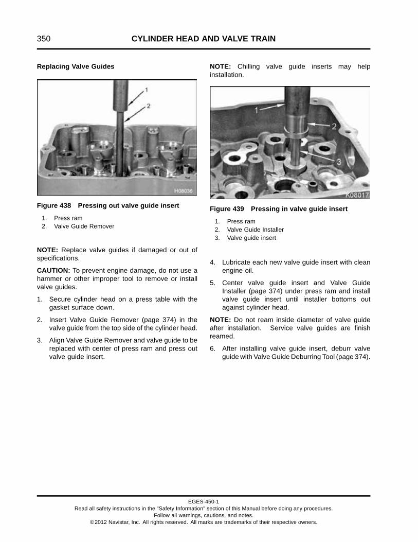
350 CYLINDER HEAD AND VALVE TRAIN
Replacing Valve Guides
Figure 438 Pressing out valve guide insert
1. Press ram2. Valve Guide Remover
NOTE: Replace valve guides if damaged or out ofspecifications.
CAUTION: To prevent engine damage, do not use ahammer or other improper tool to remove or installvalve guides.
1. Secure cylinder head on a press table with thegasket surface down.
2. Insert Valve Guide Remover (page 374) in thevalve guide from the top side of the cylinder head.
3. Align Valve Guide Remover and valve guide to bereplaced with center of press ram and press outvalve guide insert.
NOTE: Chilling valve guide inserts may helpinstallation.
Figure 439 Pressing in valve guide insert
1. Press ram2. Valve Guide Installer3. Valve guide insert
4. Lubricate each new valve guide insert with cleanengine oil.
5. Center valve guide insert and Valve GuideInstaller (page 374) under press ram and installvalve guide insert until installer bottoms outagainst cylinder head.
NOTE: Do not ream inside diameter of valve guideafter installation. Service valve guides are finishreamed.
6. After installing valve guide insert, deburr valveguide with Valve Guide Deburring Tool (page 374).
EGES-450-1Read all safety instructions in the "Safety Information" section of this Manual before doing any procedures.
Follow all warnings, cautions, and notes.©2012 Navistar, Inc. All rights reserved. All marks are trademarks of their respective owners.

CYLINDER HEAD AND VALVE TRAIN 351
Inspecting and Measurement of Valve
1. Remove carbon deposits from valve stems andvalve heads.
2. Inspect each valve for burn marks, warpage,scuffing, and bending. Replace any damagedvalves.
3. Inspect valve stem tip for scoring, pitting, or signsof excessive wear. Reface valve stem tip orreplace valve, if required.
Figure 440 Valve stem diameter measurement locations
1. Two measurements 90 degreesapart
2. Three valve stem diametermeasurement locations
4. Measure valve stem diameter with a micrometer(page 374) at three locations. At each location,take two measurements 90 degrees apart.Average the two measurements from eachlocation.
If the average of measurements at any of thethree locations is not within valve stem diameterSpecification (page 372), replace that valve.
5. Determine valve stem-to-guide running clearanceusing the valve stem diameter measurements
above and valve guide inside diametermeasurements. Subtract the average valve stemdiameter from the average valve guide insidediameter.
NOTE: Valve Stem-to-guide Running Clearance= Valve Guide Inside Diameter – Valve StemDiameter
6. Replace valve or valve guide if not withinSpecifications (page 372).
EGES-450-1Read all safety instructions in the "Safety Information" section of this Manual before doing any procedures.
Follow all warnings, cautions, and notes.©2012 Navistar, Inc. All rights reserved. All marks are trademarks of their respective owners.

352 CYLINDER HEAD AND VALVE TRAIN
Refacing Valves
Valve Face
NOTE: If valves are in good condition and withinspecifications, they may be refaced to specifiedangles.
CAUTION: To prevent engine damage, maintainminimum valve face margin across the entire valveface. An insufficient valve face margin will not allowproper heat dissipation, causing that valve to warp orbreak.
Figure 441 Grind valve face
NOTE: Make sure there is sufficient coolant in thevalve grinding machine reservoir. Turn coolant pumpon before grinding.
1. Dress the grinder cutting stone using the dressingstud attachment.
Figure 442 Valve face angles
1. Intake margin2. Intake valve angle3. Exhaust margin4. Exhaust valve angle
NOTE: Intake valves and exhaust valves havedifferent valve face margins.
2. Install valve in grinder and set grinder to specifiedintake or exhaust valve face angle (page 374).
3. Turn on coolant and grinder.
NOTE: Removal of too much material may reducevalve face margin below minimum specifications.
4. Grind valve face. Only remove the minimumamount of material necessary.
Figure 443 Valve face margin measurement
5. Measure valve face margin at four locations with avernier caliper (page 374). If any measurementsare less than minimum Specification (page 372),replace valve.
EGES-450-1Read all safety instructions in the "Safety Information" section of this Manual before doing any procedures.
Follow all warnings, cautions, and notes.©2012 Navistar, Inc. All rights reserved. All marks are trademarks of their respective owners.

CYLINDER HEAD AND VALVE TRAIN 353
Refacing Valve Stem Tip
CAUTION: To prevent engine damage, leavesufficient material on the tip of the valve stem sothe valve bridge does not contact the valve retainerkeys or valve rotator during operation. Maintain aminimum of 1.524 mm (0.060 in) gap between thevalve bridge and valve spring retainer keys.
1. Dress the cutting stone using the dressing studattachment on the grinder.
Figure 444 Valve stem grinding
2. Install valve in grinder so the tip of the valve stemis close to the grinding stone.
3. Briefly touch the tip of the valve stem to thegrinding stone. Only remove the minimumamount of material necessary.
Valve Face-to-Seat Contact Inspection
Figure 445 Marker paste application to valveface
1. After refacing a valve, spread a thin film of markerpaste (Prussian Blue® or equivalent) on the valveface and insert the valve in the valve guide.
Figure 446 Imprinting marker paste onto valveseat
2. Apply pressure to the center of the valve headwhile turning valve 90 degrees on the valve seat.
3. Remove valve from cylinder head. Inspectimpression on valve seat and valve face. Markerpaste should appear around entire contactsurface of valve seat and valve face.
4. Perform impression inspection several times torule out any errors.
• If marker paste contact impression is good,continue to Valve Spring Inspection (page358).
• If marker paste contact impression is notgood, verify correct valve face angles andthen continue to resurface valve seats. SeeResurfacing Valve Seats (page 354).
EGES-450-1Read all safety instructions in the "Safety Information" section of this Manual before doing any procedures.
Follow all warnings, cautions, and notes.©2012 Navistar, Inc. All rights reserved. All marks are trademarks of their respective owners.

354 CYLINDER HEAD AND VALVE TRAIN
Resurfacing Valve Seats
Figure 447 Valve guide pilot
1. Lightly lubricate correct size grinding pilot fromValve Seat Grinder (page 374). Install grindingpilot in valve guide.
2. Choose correct angle valve seat grinding stone(page 374) and dress stone. See Specification(page 372) for correct valve seat angle.
3. Install grinding stone over pilot.
Figure 448 Valve seat grinding
1. Motor and drive2. Holder3. Grindstone
4. Turn on grinding motor and gently apply pressureto the grindstone. Raise grinding stone frequentlyto prevent overheating. Grind valve seat to asmooth even finish, paying attention to achievinguniform width.
Figure 449 Valve seat width measurement
5. Measure valve seat width using a verniercaliper (page 374). If valve seat width exceedsSpecifications (page 372), the valve seat may becorrected by grinding with a 15 degree or smallerangle stone.
EGES-450-1Read all safety instructions in the "Safety Information" section of this Manual before doing any procedures.
Follow all warnings, cautions, and notes.©2012 Navistar, Inc. All rights reserved. All marks are trademarks of their respective owners.

CYLINDER HEAD AND VALVE TRAIN 355
Figure 450 Measuring valve recession
6. Install each valve in its valve guide. Use adepth micrometer (page 374) to measure valverecession and check Specification (page 372).
• If valve recedes too far into head, install a newvalve or replace valve seat. Reinspect valveface-to-seat contact (page 353).
• If valve protrudes above cylinder headsurface, regrind valve seat. After regrindingvalve seat, check valve seat width again.Reinspect valve face-to-seat contact.
Replacing Valve Seats
Removal
Figure 451 Valve seat groove grinder
1. Air motor2. Grinding base3. Grinding wheel4. Valve seat insert
NOTE: Replace valve seats if damaged or out ofspecifications.
1. Carefully grind a groove in valve seat insertto be removed using Valve Seat Extractor Kit(Universal) (page 374). Do not grind into cylinderhead.
EGES-450-1Read all safety instructions in the "Safety Information" section of this Manual before doing any procedures.
Follow all warnings, cautions, and notes.©2012 Navistar, Inc. All rights reserved. All marks are trademarks of their respective owners.

356 CYLINDER HEAD AND VALVE TRAIN
Figure 452 Removing valve seat insert
1. Lifting bridge2. Valve Seat Remover (collet)
2. Position appropriate size Valve Seat Remover(collet) (page 374) in valve seat.
3. Expand collet by threading shaft into valveseat remover until tight inside valve seat. TurnT-handle on shaft to pull valve seat insert out ofcylinder head.
Figure 453 Valve seat insert removal
1. Collet2. Valve seat insert
4. Unlock collet by loosening threaded shaft anddiscard valve seat insert.
EGES-450-1Read all safety instructions in the "Safety Information" section of this Manual before doing any procedures.
Follow all warnings, cautions, and notes.©2012 Navistar, Inc. All rights reserved. All marks are trademarks of their respective owners.

CYLINDER HEAD AND VALVE TRAIN 357
Installation
Figure 454 Valve seat counterbore
1. Measure valve seat counterbore diameter at twolocations 90° apart, using an inside micrometer(page 374). Average the two measurements todetermine the appropriate size valve seat insertto install.
CAUTION: To prevent engine damage, maintainproper diametral interference between valve seatinsert outside diameter and valve seat counterborediameter.
Valve Seat Insert Selection Chart
Available inserts (Intakeand Exhaust)
Intake counterbore averagediameter
Exhaust counterbore averagediameter
Standard 40.120 to 40.170 mm (1.5795 to1.5815 in)
37.478 to 37.528 mm (1.4755 to1.4775 in)
Oversize - 0.05 mm (0.002 in) 40.170 to 40.220 mm (1.5815 to1.5835 in)
37.529 to 37.579 mm (1.4775 to1.4795 in)
EGES-450-1Read all safety instructions in the "Safety Information" section of this Manual before doing any procedures.
Follow all warnings, cautions, and notes.©2012 Navistar, Inc. All rights reserved. All marks are trademarks of their respective owners.

358 CYLINDER HEAD AND VALVE TRAIN
2. Chill valve seat insert in a freezer for 30 minutes.This will slightly shrink insert and prevent theouter layer of metal from being shaved off duringinstallation.
Figure 455 Valve seat insert
3. Align chilled valve seat insert over counterbore.
Figure 456 Valve seat insert installation
4. Carefully drive valve seat into place, until fullyseated, using a hammer and Valve Seat Installer(page 374).
5. Grind new valve seats to specified angles andwidths.
Valve Spring Inspection
CAUTION: To prevent engine damage, do not grindvalve springs or use a wire brush for cleaning.Disruption of spring surface may cause fatigue cracksand spring failure.
1. Clean valve springs in a suitable solvent.
2. Inspect valve springs for rust, cracks, and pitting.Replace any damaged valve springs.
Figure 457 Valve spring
1. Cutoff end2. Wear notch3. Adjacent coil4. Push here
3. Inspect both ends of each valve spring at contactpoints between the cutoff end of the last coil andthe adjacent coil. If the cutoff end has worn anotch in the adjacent coil, replace the spring.
NOTE: Valve spring wear notches can also bedetected by compressing the spring and listeningfor a clicking sound.
EGES-450-1Read all safety instructions in the "Safety Information" section of this Manual before doing any procedures.
Follow all warnings, cautions, and notes.©2012 Navistar, Inc. All rights reserved. All marks are trademarks of their respective owners.

CYLINDER HEAD AND VALVE TRAIN 359
Figure 458 Measuring perpendicularity andflatness of valve spring
NOTE: Valve springs that are not perpendicular to aflat surface put an unequal load on the valve stem,causing premature valve and valve guide wear.
4. Use a square (page 374) to check flatness andperpendicularity of spring ends. If the end of anyvalve spring is not flat and square, replace spring. Figure 459 Measuring valve spring tension
5. Use a Valve and Clutch Spring Tester (page374) to measure valve spring tension. Measurethe maximum and minimum lengths of the springat appropriate test loads (valve closed and valveopen). Replace any valve spring that does notmeet Specifications (page 372).
EGES-450-1Read all safety instructions in the "Safety Information" section of this Manual before doing any procedures.
Follow all warnings, cautions, and notes.©2012 Navistar, Inc. All rights reserved. All marks are trademarks of their respective owners.

360 CYLINDER HEAD AND VALVE TRAIN
Inspecting Valve Rotators and Retainers
1. Clean all valve rotators and retainers in a suitablesolvent.
CAUTION: To prevent engine damage, install rotatorson intake valves.
NOTE: Some low horse power engines have retainerson the exhaust valves. Rotators must be used onintake valves and can be used on exhaust valves toextend valve life.
2. Inspect valve retainers and rotators for wear,deformation, cracking, or corrosion. Replace ifdamaged.
Figure 460 Inspecting valve rotator
1. Ram2. Steel ball bearing3. Paint reference line4. Spring5. Valve rotator
WARNING: To prevent personal injuryor death, suitable protection must be placedbetween tester and rotator and ram of Valve andClutch Spring Tester.
3. Lubricate valve rotator with clean engine oil.Place valve spring and rotator in Valve and ClutchSpring Tester.
4. Place a ball bearing between the valve rotator andram of the spring tester. The ball bearing mustbe large enough to prevent the ram from touchingany part of the rotator.
5. Paint a reference line on the valve rotator andspring.
6. Compress valve spring repeatedly and rapidlywith even pressure and observe the valve rotatoras it turns. Replace any valve rotator that doesnot turn.
Inspecting Valve Spring Retainer Keys
1. Clean all valve spring retainer keys with a suitablesolvent.
2. Check the inside and outside of the valve springretainer keys for wear. Replace any worn retainerkeys.
EGES-450-1Read all safety instructions in the "Safety Information" section of this Manual before doing any procedures.
Follow all warnings, cautions, and notes.©2012 Navistar, Inc. All rights reserved. All marks are trademarks of their respective owners.

CYLINDER HEAD AND VALVE TRAIN 361
Replacing Fuel Injector Sleeves
Removal
NOTE: Replace injector sleeves if damaged orexcessively worn.
NOTE: If removing fuel injector sleeves with enginein-chassis, place a cup plug in injector bore beforesleeve removal to prevent debris from enteringcylinder.
1. Lubricate thread tap, part of Injector SleeveRemover (page 374).
2. Insert thread tap in fuel injector sleeve.
3. Screw thread tap into fuel injector sleeve. Cutthreads at least ¾ inch deep to accommodate fuelinjector sleeve puller.
NOTE: Ensure fuel injector sleeve puller threadssufficiently into fuel injector sleeve.
4. Insert fuel injector sleeve puller, part of InjectorSleeve Remover (page 374) into fuel injectorsleeve and tighten. Make sure puller tool isthreaded all the way into fuel injector sleeve.
5. Install appropriate adapter from Slide HammerPuller Set (page 374) on fuel injector sleeve pullertool, and remove fuel injector sleeve from injectorbore.
Figure 461 Cleaning fuel injector bore
6. Using a stiff wire brush from the Injector SleeveBrush Set (set of 2) (page 374), clean depositsand hardened sealant from the fuel injector bore.
7. Insert a small stiff nylon brush tool into oil galleryfor cleaning.
WARNING: To prevent personal injury ordeath, wear safety glasses. Limit compressed airpressure to 207 kPa (30 psi).
8. Use compressed air to clean out all fuel and oilgalleries.
Installation
1. Use an Injector Sleeve Installer (page 374) thatdoes not have a bent pilot shaft or any nicks wherethe sleeve will seat.
2. Install a new fuel injector sleeve on the end of theInjector Sleeve Installer.
Figure 462 Applying sealant to fuel injectorsleeve
3. Apply Loctite® 620 Retaining Compound (page374) around outside bottom of injector sleeve andaround beginning of taper at middle of sleeve.
EGES-450-1Read all safety instructions in the "Safety Information" section of this Manual before doing any procedures.
Follow all warnings, cautions, and notes.©2012 Navistar, Inc. All rights reserved. All marks are trademarks of their respective owners.

362 CYLINDER HEAD AND VALVE TRAIN
Figure 463 Fuel injector sleeve and injector bore
4. Insert fuel injector sleeve and Injector SleeveInstaller into injector bore.
Figure 464 Installing fuel injector sleeve
5. Carefully drive fuel injector sleeve into injectorbore with a hammer.
6. Clean fuel injector sleeve with a soft nylon brush.
7. Inspect inside surfaces of installed fuel injectorsleeve. If nicked or scratched, replace sleeveagain. Make sure Injector Sleeve Installer is notcausing damage. Use a different Injector SleeveInstaller, if necessary.
EGES-450-1Read all safety instructions in the "Safety Information" section of this Manual before doing any procedures.
Follow all warnings, cautions, and notes.©2012 Navistar, Inc. All rights reserved. All marks are trademarks of their respective owners.

CYLINDER HEAD AND VALVE TRAIN 363
Installing Valves
Cleaning
WARNING: To prevent personal injury ordeath, wear safety glasses with side shields.
1. Clean valve faces and seats with a suitablesolvent. Dry all components using filteredcompressed air.
2. To clean valve guides, coat a brush with soapand water. Insert brush into each valve guidebore and rotate in one direction with an up anddown motion. Dry valve guide bores using filteredcompressed air.
Assembly
Figure 465 Valve stem seal, spring, and rotator
1. Valve stem seal2. Valve stem3. Valve rotator or retainer (typical)4. Valve spring
1. Lubricate valve stem with clean engine oil andinsert valve in valve guide.
2. Lubricate inside diameter of new valve stem sealswith clean engine oil. Install seals over valve
stems and valve guides. Make sure seals arecompletely seated against cylinder head springpockets.
3. Install valve springs over valve stem seals.
CAUTION: To prevent engine damage, rotators mustbe installed on intake valves.
4. Install valve rotators on top of intake valve springs.Install valve rotators or retainers on top of exhaustvalve springs.
Figure 466 Valve Spring Compressor andretainer keys
1. Valve Spring Compressor2. Valve spring retainer keys
WARNING: To prevent personal injury ordeath, wear safety glasses with side shields.
5. Install Valve Spring Compressor (page 374) overvalve and compress valve spring.
6. Install valve spring retainer keys and releasespring compressor.
EGES-450-1Read all safety instructions in the "Safety Information" section of this Manual before doing any procedures.
Follow all warnings, cautions, and notes.©2012 Navistar, Inc. All rights reserved. All marks are trademarks of their respective owners.

364 CYLINDER HEAD AND VALVE TRAIN
InstallationRoller Tappets and Guides
Figure 467 Roller tappets and guides
1. Roller tappet guide (2)2. Roller tappet (2)3. Crankcase
1. Lubricate roller tappets with clean engine oil.
2. Install each roller tappet and two guides intotappet bore. Install used roller tappets in theiroriginal locations, revolving in the same directionas before removal.
Cylinder Head
CAUTION: To prevent engine damage, measurecylinder sleeve protrusion (page 424) and verifywithin specification before installing cylinder headand adjust as needed.
1. Install two lifting eyes with four M12 x 25 bolts ontocylinder head. Tighten bolts to standard torque(page 523).
WARNING: To prevent personal injury ordeath, wear safety glasses with side shields.Limit compressed air pressure to 207 kPa (30 psi).
2. Clean head bolt holes in crankcase of oil anddebris with Head Bolt Bottoming Tap (page 374).Dry with filtered compressed air. Clean and drycylinder head gasket surfaces.
Figure 468 Cylinder head alignment dowel
3. Install or verify two alignment dowels are correctlyinstalled in top of crankcase.
EGES-450-1Read all safety instructions in the "Safety Information" section of this Manual before doing any procedures.
Follow all warnings, cautions, and notes.©2012 Navistar, Inc. All rights reserved. All marks are trademarks of their respective owners.
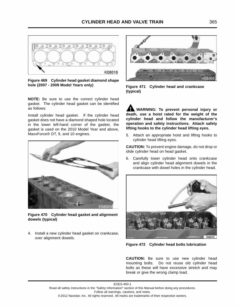
CYLINDER HEAD AND VALVE TRAIN 365
Figure 469 Cylinder head gasket diamond shapehole (2007 - 2009 Model Years only)
NOTE: Be sure to use the correct cylinder headgasket. The cylinder head gasket can be identifiedas follows:
Install cylinder head gasket. If the cylinder headgasket does not have a diamond shaped hole locatedin the lower left-hand corner of the gasket, thegasket is used on the 2010 Model Year and above,MaxxForce® DT, 9, and 10 engines.
Figure 470 Cylinder head gasket and alignmentdowels (typical)
4. Install a new cylinder head gasket on crankcase,over alignment dowels.
Figure 471 Cylinder head and crankcase(typical)
WARNING: To prevent personal injury ordeath, use a hoist rated for the weight of thecylinder head and follow the manufacturer’soperation and safety instructions. Attach safetylifting hooks to the cylinder head lifting eyes.
5. Attach an appropriate hoist and lifting hooks tocylinder head lifting eyes.
CAUTION: To prevent engine damage, do not drop orslide cylinder head on head gasket.
6. Carefully lower cylinder head onto crankcaseand align cylinder head alignment dowels in thecrankcase with dowel holes in the cylinder head.
Figure 472 Cylinder head bolts lubrication
CAUTION: Be sure to use new cylinder headmounting bolts. Do not reuse old cylinder headbolts as these will have excessive stretch and maybreak or give the wrong clamp load.
EGES-450-1Read all safety instructions in the "Safety Information" section of this Manual before doing any procedures.
Follow all warnings, cautions, and notes.©2012 Navistar, Inc. All rights reserved. All marks are trademarks of their respective owners.

366 CYLINDER HEAD AND VALVE TRAIN
CAUTION: Do not use chlorinated solvents oncylinder head bolts. Parts should be clean, dry, andfree of chemicals other than engine oil.
7. Install new cylinder head mounting bolts. Lightlylubricate the threads and bolt flange of each withclean engine oil.
8. Install all the new cylinder head bolts finger tight.
Torque Procedure for Torque-to-yield Head Bolts
Figure 473 Cylinder head torque sequence A
1. Rotate crankshaft to TDC for Cylinder 1. Thenrotate crankshaft 30 degrees past TDC.
NOTE: It is necessary to torque cylinder headbolts three times before doing final torque-to-yieldprocedure in order to obtain uniform head bolt torque.
2. Torque each cylinder head bolt to 150 N·m (110lbf·ft) in cylinder head torque sequence A.
3. Retorque each cylinder head bolt to 238 N·m (175lbf·ft) in cylinder head torque sequence A.
EGES-450-1Read all safety instructions in the "Safety Information" section of this Manual before doing any procedures.
Follow all warnings, cautions, and notes.©2012 Navistar, Inc. All rights reserved. All marks are trademarks of their respective owners.

CYLINDER HEAD AND VALVE TRAIN 367
H08105
1 2 3 4 5 6
7 8 9 10 11 12 13
14 15 16 17 18 19 20
21 22 23 24 25 26
Figure 474 Cylinder head torque sequence B
4. Torque each cylinder head bolt again to 238 N·m(175 lbf·ft) in cylinder head torque sequence B.
Figure 475 Head bolt torque-to-yield marking
1. Top of head bolt before Torque-to-Yield2. Top of head bolt after Torque-to-Yield3. Mark on cylinder head surface
CAUTION: To prevent engine damage, usepermanent marker to identify internal enginecomponents and their orientation. Do not use paintor temporary markers.
5. Using a permanent marker, place a mark on eachhead bolt and put another mark on the head boltsocket (page 374) directly in line with the mark oneach head bolt.
6. Put a mark on the cylinder head surface 90°clockwise from each head bolt mark.
7. Install head bolt socket on head bolt to be torquedand align mark on socket with the mark on thehead bolt.
8. Torque-to-yield each cylinder head bolt by rotatingbolt 90 degrees clockwise (1/4 turn) in cylinderhead torque sequence A (Figure 473). The markson the head bolt socket, head bolt, and cylinderhead surface should be aligned.
EGES-450-1Read all safety instructions in the "Safety Information" section of this Manual before doing any procedures.
Follow all warnings, cautions, and notes.©2012 Navistar, Inc. All rights reserved. All marks are trademarks of their respective owners.

368 CYLINDER HEAD AND VALVE TRAIN
Rocker Arms
NOTE: See Fuel Injector Assemblies for fuel injectorinstallation (page 204).
Figure 476 Rocker arm configuration
1. M8 x 60 shaft bolt2. Exhaust rocker arm3. Rocker arm shaft support4. Support washer (assembly aid)5. Machined recess6. Intake rocker arm
1. Slide 12 rocker arms onto rocker shaft in orderremoved (rocker arms should have been markedduring removal procedure).
NOTE: Ensure rocker arm shaft has big “T” stampfacing up.
2. Install twelve shaft bolts through rocker arm shaftand into rocker arm shaft supports.
3. Install a support washer (assembly aid) onto eachintake rocker arm shaft bolt (recessed side of shaftsupport only).
Rocker Arm Assembly
Figure 477 Valve bridge installation
1. Install valve bridges on each set of intake andexhaust valve stems. Used valve bridges must bereinstalled in their original location and orientation.(See marks from removal.)
EGES-450-1Read all safety instructions in the "Safety Information" section of this Manual before doing any procedures.
Follow all warnings, cautions, and notes.©2012 Navistar, Inc. All rights reserved. All marks are trademarks of their respective owners.

CYLINDER HEAD AND VALVE TRAIN 369
Figure 478 Rocker arm orientation and big “T” stamp
2. Install rocker arm shaft assembly with 12 shaftbolts and six shaft supports, onto cylinder head.
3. Align shaft bolts with mating bolt holes in cylinderhead. Finger tighten bolts.
Figure 479 Rocker arm torque sequence
NOTE: Check that all valve adjustment screwsshould be loose. They should have been loose sinceremoving the rocker arm.
4. Tighten shaft bolts in two steps using rocker armtorque sequence.
a. Torque rocker arm shaft bolts in sequence to27 N·m (20 lbf·ft).
b. Torque rocker arm shaft bolts in sequence to37 N·m (27 lbf·ft).
5. Adjust valve lash (page 333) for all 12 rockerarms.
EGES-450-1Read all safety instructions in the "Safety Information" section of this Manual before doing any procedures.
Follow all warnings, cautions, and notes.©2012 Navistar, Inc. All rights reserved. All marks are trademarks of their respective owners.

370 CYLINDER HEAD AND VALVE TRAIN
Valve Cover
1. Install the valve cover gasket on top of the cylinderhead before installing the valve cover. See ValveCover Gasket Assembly (page 108).
Figure 480 Valve cover bolts
1. Bolt, M8 x 80 (6) 2. Bolt, M8 x 25 (secures optionalradiator piping support)
3. Stud bolt, M8 x 80 (4)4. Bolt, M8 x 20
EGES-450-1Read all safety instructions in the "Safety Information" section of this Manual before doing any procedures.
Follow all warnings, cautions, and notes.©2012 Navistar, Inc. All rights reserved. All marks are trademarks of their respective owners.

CYLINDER HEAD AND VALVE TRAIN 371
2. Install valve cover and finger tighten saved fourM8 x 80 stud bolts and six M8 x 80 bolts. Tightento standard torque (page 523).
Figure 481 Clipping plate
1. Clipping plate2. M8 x 25 bolt (2)
3. Install two M8 x 25 bolts securing the clippingplate to the valve cover. Tighten bolts to standardtorque (page 523).
EGES-450-1Read all safety instructions in the "Safety Information" section of this Manual before doing any procedures.
Follow all warnings, cautions, and notes.©2012 Navistar, Inc. All rights reserved. All marks are trademarks of their respective owners.

372 CYLINDER HEAD AND VALVE TRAIN
Specifications
Valve Specifications
Intake:
6.68 mm (0.263 in)
0.254 mm (0.010 in) maximum wear limit
Camshaft lobe lift
Exhaust:
6.91 mm (0.272 in)
0.254 mm (0.010 in) maximum wear limit
Roller tappet guide slot width 9.271 ± 0.05 mm (0.365 ± 0.002 in)
Intake:
59.75 to 60.00°
Valve face angle
Exhaust:
44.75 to 45.00°
Intake:
1.32 mm (0.052 in)
Valve face margin (minimum)
Exhaust:
1.16 mm (0.046 in)
Valve face-to-valve stem runout (maximum) 0.038 mm (0.0015 in)
Valve lash (cold), intake and exhaust 0.48 mm (0.019 in)
Valve stem diameter (new condition) Intake:
7.92861 ± 0.0089 mm (0.31215 ± 0.00035 in)
Exhaust:
7.9083 ± 0.0089 mm (0.31135 ± 0.00035 in)
Valve stem straightness (maximum) 0.010 mm (0.0004 in)
Valve stem-to-guide running clearance (maximum) Intake:
0.10 mm (0.004 in)
Exhaust:
0.11 mm (0.005 in)
Intake valve head diameter 39.73 ± 0.13 mm (1.564 ± 0.005 in)
Exhaust valve head diameter 36.55 ± 0.13 mm (1.439 ± 0.005 in)
EGES-450-1Read all safety instructions in the "Safety Information" section of this Manual before doing any procedures.
Follow all warnings, cautions, and notes.©2012 Navistar, Inc. All rights reserved. All marks are trademarks of their respective owners.
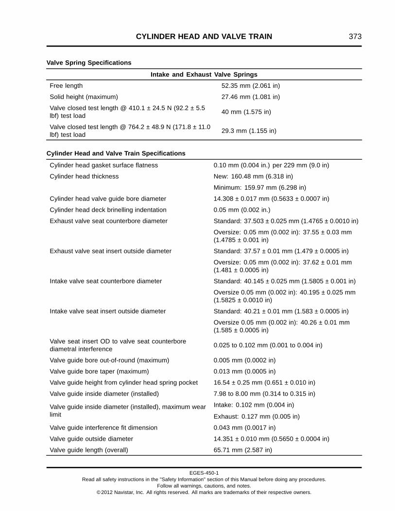
CYLINDER HEAD AND VALVE TRAIN 373
Valve Spring Specifications
Intake and Exhaust Valve Springs
Free length 52.35 mm (2.061 in)
Solid height (maximum) 27.46 mm (1.081 in)
Valve closed test length @ 410.1 ± 24.5 N (92.2 ± 5.5lbf) test load 40 mm (1.575 in)
Valve closed test length @ 764.2 ± 48.9 N (171.8 ± 11.0lbf) test load 29.3 mm (1.155 in)
Cylinder Head and Valve Train Specifications
Cylinder head gasket surface flatness 0.10 mm (0.004 in.) per 229 mm (9.0 in)
New: 160.48 mm (6.318 in)Cylinder head thickness
Minimum: 159.97 mm (6.298 in)
Cylinder head valve guide bore diameter 14.308 ± 0.017 mm (0.5633 ± 0.0007 in)
Cylinder head deck brinelling indentation 0.05 mm (0.002 in.)
Standard: 37.503 ± 0.025 mm (1.4765 ± 0.0010 in)Exhaust valve seat counterbore diameter
Oversize: 0.05 mm (0.002 in): 37.55 ± 0.03 mm(1.4785 ± 0.001 in)
Standard: 37.57 ± 0.01 mm (1.479 ± 0.0005 in)Exhaust valve seat insert outside diameter
Oversize: 0.05 mm (0.002 in): 37.62 ± 0.01 mm(1.481 ± 0.0005 in)
Standard: 40.145 ± 0.025 mm (1.5805 ± 0.001 in)Intake valve seat counterbore diameter
Oversize 0.05 mm (0.002 in): 40.195 ± 0.025 mm(1.5825 ± 0.0010 in)
Standard: 40.21 ± 0.01 mm (1.583 ± 0.0005 in)Intake valve seat insert outside diameter
Oversize 0.05 mm (0.002 in): 40.26 ± 0.01 mm(1.585 ± 0.0005 in)
Valve seat insert OD to valve seat counterborediametral interference 0.025 to 0.102 mm (0.001 to 0.004 in)
Valve guide bore out-of-round (maximum) 0.005 mm (0.0002 in)
Valve guide bore taper (maximum) 0.013 mm (0.0005 in)
Valve guide height from cylinder head spring pocket 16.54 ± 0.25 mm (0.651 ± 0.010 in)
Valve guide inside diameter (installed) 7.98 to 8.00 mm (0.314 to 0.315 in)
Valve guide inside diameter (installed), maximum wearlimit
Intake: 0.102 mm (0.004 in)
Exhaust: 0.127 mm (0.005 in)
Valve guide interference fit dimension 0.043 mm (0.0017 in)
Valve guide outside diameter 14.351 ± 0.010 mm (0.5650 ± 0.0004 in)
Valve guide length (overall) 65.71 mm (2.587 in)
EGES-450-1Read all safety instructions in the "Safety Information" section of this Manual before doing any procedures.
Follow all warnings, cautions, and notes.©2012 Navistar, Inc. All rights reserved. All marks are trademarks of their respective owners.

374 CYLINDER HEAD AND VALVE TRAIN
Cylinder Head and Valve Train Specifications (cont.)
Intake:
1.02 ± 0.13 mm (0.040 ± 0.005 in)
Valve recession
Exhaust:
1.40 ± 0.13 mm (0.055 ± 0.005 in)
Intake:
59.75 - 60°
Valve seat angles
Exhaust:
44.75 - 45°
Valve seat to valve guide bore concentricity (maximum) 0.076 mm (0.003 in)
Valve seat width 1.91 to 2.16 mm (0.075 to 0.085 in)
Push rod runout (maximum) 0.508 mm (0.020 in)
Special Torque
Cylinder head mounting bolts torque and sequence See Torque Procedure for Torque-to-yieldHead Bolts (page 366)
Rocker arm bolts torque and sequence See torque procedure in Rocker ArmAssembly (page 368)
Valve adjustment screw lock nut 27 N·m (20 lbf·ft)
Special Service Tools
Ball gauge Obtain locally
Cylinder Head Test Plate ZTSE4289A
Depth micrometer Obtain locally
Dial indicator set Obtain locally
Dye penetrant kit Obtain locally
Feeler gauge Obtain locally
Head bolt socket Obtain locally
Head Bolt Bottoming Tap ZTSE4671
Injector Sleeve Brush Set (set of 2) ZTSE4304
Injector Sleeve Installer ZTSE4642
Injector Sleeve Remover ZTSE4643–1A
Inside micrometer Obtain locally
Loctite® 620 Retaining Compound Obtain locally
EGES-450-1Read all safety instructions in the "Safety Information" section of this Manual before doing any procedures.
Follow all warnings, cautions, and notes.©2012 Navistar, Inc. All rights reserved. All marks are trademarks of their respective owners.

CYLINDER HEAD AND VALVE TRAIN 375
Outside micrometer Obtain locally
Prussian® Blue Obtain locally
Pressure regulator Obtain locally
Slide Hammer Puller Set ZTSE1879
Small hole gauge set Obtain locally
Square Obtain locally
Straightedge Obtain locally
Telescoping gauge Obtain locally
Thermostat Opening Pressure Adapter ZTSE4647
Valve and Clutch Spring Tester ZTSE2241
Valve Guide Deburring Tool ZTSE4393
Valve Guide Installer ZTSE1943
Valve Guide Remover ZTSE4377
Valve Seat Extractor Kit (Universal) ZTSE1951C
Valve Seat Grinder ZTSE1631A
Valve seat grinding stones 45° (exhaust) Obtain locally
Valve seat grinding stones 60° (intake) Obtain locally
Valve Seat Installer ZTSE4641
Valve Seat Remover (collet) ZTSE4640
Valve Spring Compressor ZTSE1846
Valve Spring Compressor Jaws ZTSE4652
Vernier caliper Obtain locally
Water Supply Housing Pressure Adapter ZTSE4648
EGES-450-1Read all safety instructions in the "Safety Information" section of this Manual before doing any procedures.
Follow all warnings, cautions, and notes.©2012 Navistar, Inc. All rights reserved. All marks are trademarks of their respective owners.

376 CYLINDER HEAD AND VALVE TRAIN
EGES-450-1Read all safety instructions in the "Safety Information" section of this Manual before doing any procedures.
Follow all warnings, cautions, and notes.©2012 Navistar, Inc. All rights reserved. All marks are trademarks of their respective owners.
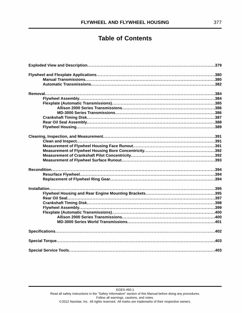
FLYWHEEL AND FLYWHEEL HOUSING 377
Table of Contents
Exploded View and Description. . . . . . . . . . . . . . . . . . . . . . . . . . . . . . . . . . . . . . . . . . . . . . . . . . . . . . . . . . . . . . . . . . . . . . . . . . . . . . . . . . . . .379
Flywheel and Flexplate Applications. . . . . . . . . . . . . . . . . . . . . . . . . . . . . . . . . . . . . . . . . . . . . . . . . . . . . . . . . . . . . . . . . . . . . . . . . . . . . . .380Manual Transmissions.. . . . . . . . . . . . . . . . . . . . . . . . . . . . . . . . . . . . . . . . . . . . . . . . . . . . . . . . . . . . . . . . . . . . . . . . . . . . . . . . . . . . .380Automatic Transmissions.. . . . . . . . . . . . . . . . . . . . . . . . . . . . . . . . . . . . . . . . . . . . . . . . . . . . . . . . . . . . . . . . . . . . . . . . . . . . . . . . . .382
Removal. . . . . . . . . . . . . . . . . . . . . . . . . . . . . . . . . . . . . . . . . . . . . . . . . . . . . . . . . . . . . . . . . . . . . . . . . . . . . . . . . . . . . . . . . . . . . . . . . . . . . . . . . . . . . . . . .384Flywheel Assembly. . . . . . . . . . . . . . . . . . . . . . . . . . . . . . . . . . . . . . . . . . . . . . . . . . . . . . . . . . . . . . . . . . . . . . . . . . . . . . . . . . . . . . . . . .384Flexplate (Automatic Transmissions). . . . . . . . . . . . . . . . . . . . . . . . . . . . . . . . . . . . . . . . . . . . . . . . . . . . . . . . . . . . . . . . . . . . .385
Allison 2000 Series Transmissions.. . . . . . . . . . . . . . . . . . . . . . . . . . . . . . . . . . . . . . . . . . . . . . . . . . . . . . . . . . . . .386MD-3000 Series Transmissions. . . . . . . . . . . . . . . . . . . . . . . . . . . . . . . . . . . . . . . . . . . . . . . . . . . . . . . . . . . . . . . . . .386
Crankshaft Timing Disk. . . . . . . . . . . . . . . . . . . . . . . . . . . . . . . . . . . . . . . . . . . . . . . . . . . . . . . . . . . . . . . . . . . . . . . . . . . . . . . . . . . . .387Rear Oil Seal Assembly. . . . . . . . . . . . . . . . . . . . . . . . . . . . . . . . . . . . . . . . . . . . . . . . . . . . . . . . . . . . . . . . . . . . . . . . . . . . . . . . . . . . .388Flywheel Housing.. . . . . . . . . . . . . . . . . . . . . . . . . . . . . . . . . . . . . . . . . . . . . . . . . . . . . . . . . . . . . . . . . . . . . . . . . . . . . . . . . . . . . . . . . . .389
Cleaning, Inspection, and Measurement. . . . . . . . . . . . . . . . . . . . . . . . . . . . . . . . . . . . . . . . . . . . . . . . . . . . . . . . . . . . . . . . . . . . . . . . . . .391Clean and Inspect. . . . . . . . . . . . . . . . . . . . . . . . . . . . . . . . . . . . . . . . . . . . . . . . . . . . . . . . . . . . . . . . . . . . . . . . . . . . . . . . . . . . . . . . . . . .391Measurement of Flywheel Housing Face Runout. . . . . . . . . . . . . . . . . . . . . . . . . . . . . . . . . . . . . . . . . . . . . . . . . . . . . . .391Measurement of Flywheel Housing Bore Concentricity. . . . . . . . . . . . . . . . . . . . . . . . . . . . . . . . . . . . . . . . . . . . . . .392Measurement of Crankshaft Pilot Concentricity. . . . . . . . . . . . . . . . . . . . . . . . . . . . . . . . . . . . . . . . . . . . . . . . . . . . . . . .392Measurement of Flywheel Surface Runout. . . . . . . . . . . . . . . . . . . . . . . . . . . . . . . . . . . . . . . . . . . . . . . . . . . . . . . . . . . . . .393
Recondition. . . . . . . . . . . . . . . . . . . . . . . . . . . . . . . . . . . . . . . . . . . . . . . . . . . . . . . . . . . . . . . . . . . . . . . . . . . . . . . . . . . . . . . . . . . . . . . . . . . . . . . . . . . . .394Resurface Flywheel. . . . . . . . . . . . . . . . . . . . . . . . . . . . . . . . . . . . . . . . . . . . . . . . . . . . . . . . . . . . . . . . . . . . . . . . . . . . . . . . . . . . . . . . . .394Replacement of Flywheel Ring Gear. . . . . . . . . . . . . . . . . . . . . . . . . . . . . . . . . . . . . . . . . . . . . . . . . . . . . . . . . . . . . . . . . . . . . .394
Installation. . . . . . . . . . . . . . . . . . . . . . . . . . . . . . . . . . . . . . . . . . . . . . . . . . . . . . . . . . . . . . . . . . . . . . . . . . . . . . . . . . . . . . . . . . . . . . . . . . . . . . . . . . . . . .395Flywheel Housing and Rear Engine Mounting Brackets. . . . . . . . . . . . . . . . . . . . . . . . . . . . . . . . . . . . . . . . . . . . . .395Rear Oil Seal. . . . . . . . . . . . . . . . . . . . . . . . . . . . . . . . . . . . . . . . . . . . . . . . . . . . . . . . . . . . . . . . . . . . . . . . . . . . . . . . . . . . . . . . . . . . . . . . . . .397Crankshaft Timing Disk. . . . . . . . . . . . . . . . . . . . . . . . . . . . . . . . . . . . . . . . . . . . . . . . . . . . . . . . . . . . . . . . . . . . . . . . . . . . . . . . . . . . .398Flywheel Assembly. . . . . . . . . . . . . . . . . . . . . . . . . . . . . . . . . . . . . . . . . . . . . . . . . . . . . . . . . . . . . . . . . . . . . . . . . . . . . . . . . . . . . . . . . .399Flexplate (Automatic Transmissions). . . . . . . . . . . . . . . . . . . . . . . . . . . . . . . . . . . . . . . . . . . . . . . . . . . . . . . . . . . . . . . . . . . . .400
Allison 2000 Series Transmissions.. . . . . . . . . . . . . . . . . . . . . . . . . . . . . . . . . . . . . . . . . . . . . . . . . . . . . . . . . . . . .400MD-3000 Series World Transmissions.. . . . . . . . . . . . . . . . . . . . . . . . . . . . . . . . . . . . . . . . . . . . . . . . . . . . . . . . .401
Specifications. . . . . . . . . . . . . . . . . . . . . . . . . . . . . . . . . . . . . . . . . . . . . . . . . . . . . . . . . . . . . . . . . . . . . . . . . . . . . . . . . . . . . . . . . . . . . . . . . . . . . . . . . .402
Special Torque.. . . . . . . . . . . . . . . . . . . . . . . . . . . . . . . . . . . . . . . . . . . . . . . . . . . . . . . . . . . . . . . . . . . . . . . . . . . . . . . . . . . . . . . . . . . . . . . . . . . . . . . . .403
Special Service Tools. . . . . . . . . . . . . . . . . . . . . . . . . . . . . . . . . . . . . . . . . . . . . . . . . . . . . . . . . . . . . . . . . . . . . . . . . . . . . . . . . . . . . . . . . . . . . . . . .403
EGES-450-1Read all safety instructions in the "Safety Information" section of this Manual before doing any procedures.
Follow all warnings, cautions, and notes.©2012 Navistar, Inc. All rights reserved. All marks are trademarks of their respective owners.

378 FLYWHEEL AND FLYWHEEL HOUSING
EGES-450-1Read all safety instructions in the "Safety Information" section of this Manual before doing any procedures.
Follow all warnings, cautions, and notes.©2012 Navistar, Inc. All rights reserved. All marks are trademarks of their respective owners.

FLYWHEEL AND FLYWHEEL HOUSING 379
Exploded View and Description
Figure 482 Flywheel housing and related parts (typical)
1. M12 x 40 bolt (8)2. Rear engine mounting bracket
(2)3. Flywheel housing
4. Crankshaft Position sensor(CKP)
5. M6 x 16 bolt6. Copper fuel line clip
7. Flywheel housing seal8. Cover plate9. M6 x 16 bolt (2)10. Hollow dowel (2)
The flywheel housing assembly is bolted to the backof the crankcase and supports the transmission,starter motor, rear engine mounting brackets, andcrankshaft position sensor. A flywheel and clutchassembly (manual transmission) or a flexplate and
torque converter assembly (automatic transmission)are housed inside the flywheel housing to transferengine power to the transmission. Several flywheelhousing, flywheel, and flexplate options are availableto fit different applications.
EGES-450-1Read all safety instructions in the "Safety Information" section of this Manual before doing any procedures.
Follow all warnings, cautions, and notes.©2012 Navistar, Inc. All rights reserved. All marks are trademarks of their respective owners.

380 FLYWHEEL AND FLYWHEEL HOUSING
All transmission applications are designed to attach toone of the following four flywheel housing assemblyconfigurations:
Flywheel housing SAE 1
• Houses a flywheel or flexplate with a 148-toothring gear
• SAE 1 transmission opening
• SAE 1 starter motor location (will only work with a148-tooth ring gear)
• Standard SAE 2 side mount locations
Flywheel housing SAE 1A
• Houses a flywheel or flexplate with a 138-toothring gear
• SAE 1 transmission opening
• SAE 2 starter motor location (will only work with a138-tooth ring gear)
• Standard SAE 2 side mount locations
Flywheel housing SAE 2
• Houses a flywheel or flexplate with a 138-toothring gear
• SAE 2 transmission opening
• SAE 2 starter motor location (will only work with a138-tooth ring gear)
• Standard SAE 2 side mount locations
Flywheel housing (Bus) SAE 2
• Houses a flywheel or flexplate with a 138-toothring gear
• SAE 2 starter motor location (will only work with a138-tooth ring gear)
• High side mounts for bus
Flywheel and FlexplateApplicationsManual Transmissions
Figure 483 14 inch flywheel - for multiple plateclutch applications (800 lbf·ft and below)
1. Flywheel assembly2. M12 x 40 bolt (12)3. Crankshaft timing disk
EGES-450-1Read all safety instructions in the "Safety Information" section of this Manual before doing any procedures.
Follow all warnings, cautions, and notes.©2012 Navistar, Inc. All rights reserved. All marks are trademarks of their respective owners.
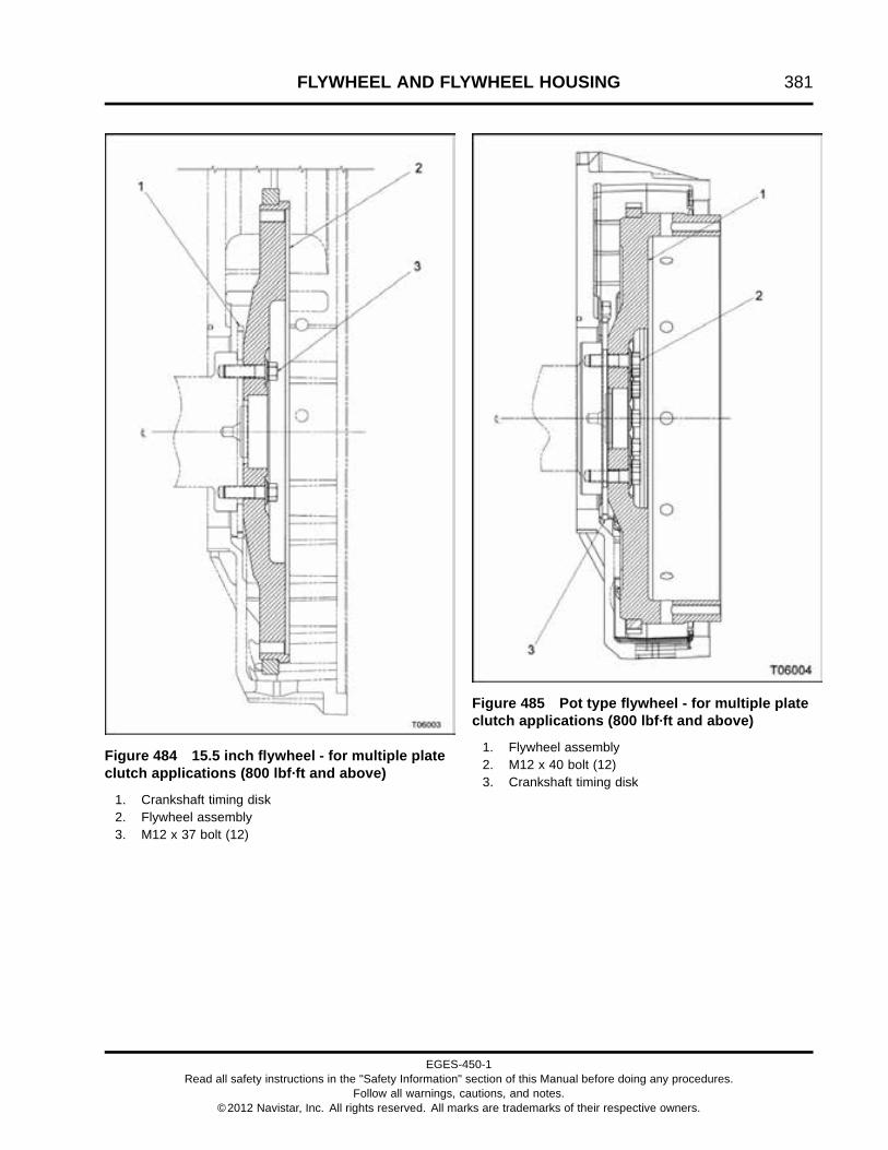
FLYWHEEL AND FLYWHEEL HOUSING 381
Figure 484 15.5 inch flywheel - for multiple plateclutch applications (800 lbf·ft and above)
1. Crankshaft timing disk2. Flywheel assembly3. M12 x 37 bolt (12)
Figure 485 Pot type flywheel - for multiple plateclutch applications (800 lbf·ft and above)
1. Flywheel assembly2. M12 x 40 bolt (12)3. Crankshaft timing disk
EGES-450-1Read all safety instructions in the "Safety Information" section of this Manual before doing any procedures.
Follow all warnings, cautions, and notes.©2012 Navistar, Inc. All rights reserved. All marks are trademarks of their respective owners.

382 FLYWHEEL AND FLYWHEEL HOUSING
Automatic Transmissions
NOTE: Side of reinforcement ring stamped with thepart number or logo must face outward.
Figure 486 Application for Allison World Transmissions - MD-3060 and MD-3560
1. Flexplate assembly2. Reinforcement ring (Allison
transmissions only)
3. M12 x 45 bolt (12)4. Crankshaft timing disk5. Adapter hub crankshaft
EGES-450-1Read all safety instructions in the "Safety Information" section of this Manual before doing any procedures.
Follow all warnings, cautions, and notes.©2012 Navistar, Inc. All rights reserved. All marks are trademarks of their respective owners.

FLYWHEEL AND FLYWHEEL HOUSING 383
NOTE: Side of reinforcement ring stamped with thepart number or logo must face outward.
Figure 487 Application for Allison transmissions
1. Crankshaft timing disk2. Ring gear & flex plate assembly3. Plate assembly, Allison AT
transmissions
4. M12 x 43 bolt (12)5. Reinforcement ring6. Adapter hub, AT7. M10 x 1.5 nut
8. Converter adapter ring (SAE 2to SAE 3 ring)
9. Transmission case10. Torque converter assembly
EGES-450-1Read all safety instructions in the "Safety Information" section of this Manual before doing any procedures.
Follow all warnings, cautions, and notes.©2012 Navistar, Inc. All rights reserved. All marks are trademarks of their respective owners.

384 FLYWHEEL AND FLYWHEEL HOUSING
Removal
WARNING: To prevent personal injury ordeath, read all safety instructions in the "SafetyInformation" section of this manual.
WARNING: To prevent personal injury ordeath, shift transmission to park or neutral, setparking brake, and block wheels before doingdiagnostic or service procedures.
WARNING: To prevent personal injury ordeath, wear safety glasses with side shields.Limit compressed air pressure to 207 kPa (30 psi).
Flywheel Assembly
WARNING: To prevent personal injury ordeath, disconnect ground (-) cable from batterybefore doing service or diagnostic procedures.
1. Disconnect the negative (ground) cable from thebattery.
2. Disconnect the electrical cable and wires from thestarter motor.
3. Remove bolts holding the starter motor to theflywheel housing and remove the starter.
4. Remove the transmission and clutch assembly.
EGES-450-1Read all safety instructions in the "Safety Information" section of this Manual before doing any procedures.
Follow all warnings, cautions, and notes.©2012 Navistar, Inc. All rights reserved. All marks are trademarks of their respective owners.
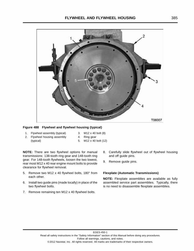
FLYWHEEL AND FLYWHEEL HOUSING 385
Figure 488 Flywheel and flywheel housing (typical)
1. Flywheel assembly (typical)2. Flywheel housing assembly
(typical)
3. M12 x 40 bolt (8)4. Ring gear5. M12 x 40 bolt (12)
NOTE: There are two flywheel options for manualtransmissions: 138-tooth ring gear and 148-tooth ringgear. For 148-tooth flywheels, loosen the two lowest,rear most M12 x 40 rear engine mount bolts to provideclearance for flywheel removal.
5. Remove two M12 x 40 flywheel bolts, 180° fromeach other.
6. Install two guide pins (made locally) in place of thetwo flywheel bolts.
7. Remove remaining ten M12 x 40 flywheel bolts.
8. Carefully slide flywheel out of flywheel housingand off guide pins.
9. Remove guide pins.
Flexplate (Automatic Transmissions)
NOTE: Flexplate assemblies are available as fullyassembled service part assemblies. Typically, thereis no need to disassemble flexplate assemblies.
EGES-450-1Read all safety instructions in the "Safety Information" section of this Manual before doing any procedures.
Follow all warnings, cautions, and notes.©2012 Navistar, Inc. All rights reserved. All marks are trademarks of their respective owners.

386 FLYWHEEL AND FLYWHEEL HOUSING
Allison 2000 Series Transmissions
Figure 489 Flexplate, reinforcement ring, andadaptor hub
1. M12 x 43 bolt (12)2. Reinforcement ring3. Paint marking index4. Adapter hub A/T5. Flexplate assembly
1. Remove transmission and torque converterassembly.
2. Put a paint mark on the exposed face of thereinforcement ring and flexplate for properinstallation orientation.
3. Remove two M12 x 43 flywheel bolts, 180° fromeach other.
4. Install two guide pins (made locally) in place of twoM12 x 43 flywheel bolts.
5. Remove remaining ten M12 x 43 flywheel bolts.
6. Slide reinforcement ring, flexplate, and adapterhub off guide pins.
7. Remove guide pins.
MD-3000 Series Transmissions
Figure 490 Flexplate, reinforcement ring, andguide pins
1. M12 x 45 bolt hole (12)2. Reinforcement ring3. Adapter crankshaft hub4. M6 flexplate assembly bolt (2)5. Flexplate assembly6. Guide pin (2)
1. Remove transmission and torque converterassembly.
CAUTION: To prevent engine or vehicle damage, donot remove two M6 flexplate assembly bolts.
2. Remove two M12 x 45 flexplate bolts, 180° fromeach other.
3. Install two guide pins (made locally) in place of twoM12 x 45 flexplate bolts.
4. Remove remaining ten M12 x 45 flexplate bolts.
5. Slide flexplate assembly off guide pins.
6. Remove guide pins.
EGES-450-1Read all safety instructions in the "Safety Information" section of this Manual before doing any procedures.
Follow all warnings, cautions, and notes.©2012 Navistar, Inc. All rights reserved. All marks are trademarks of their respective owners.

FLYWHEEL AND FLYWHEEL HOUSING 387
Crankshaft Timing Disk
CAUTION: To prevent engine damage, do not contactthe rear oil seal with bolts threaded into the crankshafttiming disk for disk removal. Damage to the rear oilseal could cause oil leaks.
Figure 491 Crankshaft timing disk removal
1. Install two bolts and washers through H-bar puller(page 403) and into the crankshaft timing disk.Install bolt heads at equal lengths from the timingdisk.
2. Tighten H-bar puller center shaft to pull timing diskoff of the crankshaft.
EGES-450-1Read all safety instructions in the "Safety Information" section of this Manual before doing any procedures.
Follow all warnings, cautions, and notes.©2012 Navistar, Inc. All rights reserved. All marks are trademarks of their respective owners.

388 FLYWHEEL AND FLYWHEEL HOUSING
Rear Oil Seal Assembly
NOTE: If the flywheel housing is to be removed, thenremove flywheel housing (page 389) first. The rear oilseal will remain in the flywheel housing and can beknocked out with a hammer.
Figure 492 Puller screw holes in rear oil sealassembly
NOTE: Use an appropriate size drill bit to fit SlideHammer Puller screw.
1. Carefully drill two puller screw holesapproximately 180° from each other in therear oil seal assembly.
Figure 493 Rear oil seal assembly and slidehammer
2. Screw Slide Hammer Puller Set (page 403) screwinto holes drilled in the rear oil seal assembly.
3. Alternately pull each side of the rear oil seal out.
4. Remove and discard rear oil seal.
NOTE: When replacing crankshaft rear oil seal, notethat production engines will not have a wear sleeve.Wear sleeves are only available as a service itemincluded with replacement crankshaft rear oil seals.
5. If installed, remove and discard wear sleeve usingSlide Hammer Puller Set (page 403).
EGES-450-1Read all safety instructions in the "Safety Information" section of this Manual before doing any procedures.
Follow all warnings, cautions, and notes.©2012 Navistar, Inc. All rights reserved. All marks are trademarks of their respective owners.

FLYWHEEL AND FLYWHEEL HOUSING 389
Flywheel Housing
1. Remove the oil pan (page 269).
Figure 494 Flywheel housing removal (typical)
1. Rear engine mounting bracket(2)
2. M12 x 40 bolt (8)3. M12 x 50 bolt (8)
WARNING: To prevent personal injury ordeath, support engine (if in chassis) beforeremoving any engine mounting bracket orflywheel housing bolts.
2. Properly support the engine and remove eightM12 x 40 rear engine mounting bracket bolts andtwo rear engine mounting brackets.
WARNING: To prevent personal injury ordeath, get assistance to remove or install theflywheel housing.
3. Remove seven of the eight M12 x 50 flywheelhousing mounting bolts.
4. Support the flywheel housing with help from anassistant.
5. Remove the final M12 x 50 flywheel housingmounting bolt and remove flywheel housing fromthe crankcase.
EGES-450-1Read all safety instructions in the "Safety Information" section of this Manual before doing any procedures.
Follow all warnings, cautions, and notes.©2012 Navistar, Inc. All rights reserved. All marks are trademarks of their respective owners.

390 FLYWHEEL AND FLYWHEEL HOUSING
Figure 495 Camshaft rear seal ring
6. Remove camshaft rear seal ring over camshaftend opening at rear of crankcase.
EGES-450-1Read all safety instructions in the "Safety Information" section of this Manual before doing any procedures.
Follow all warnings, cautions, and notes.©2012 Navistar, Inc. All rights reserved. All marks are trademarks of their respective owners.

FLYWHEEL AND FLYWHEEL HOUSING 391
Cleaning, Inspection, andMeasurement
WARNING: To prevent personal injury ordeath, wear safety glasses with side shields.Limit compressed air pressure to 207 kPa (30 psi).
Clean and Inspect
1. Clean flywheel or flexplate, flywheel housing, andrear engine mounting brackets with a non-causticsolvent and dry with filtered compressed air.
2. Inspect flywheel housing and rear enginemounting brackets for cracks and damage.Replace if required.
3. If equipped, inspect flexplate for cracks, damage,and warpage. Replace if required.
4. If equipped, inspect flywheel for cracks, heatchecks, and extensive scoring. Resurface orreplace as required.
5. Inspect crankshaft timing disk for missing, bent,chipped, or otherwise damaged gear teeth. Laytiming disk on a flat surface to ensure disk is notbent. If teeth are damaged or disk is bent, replacethe timing disk.
6. Inspect ring gear for worn, chipped, or crackedteeth. If teeth are damaged, replace the ring gear.
7. Clean and inspect crankshaft and crankcasewhere flywheel and flywheel housing mount.
Measurement of Flywheel Housing Face Runout
Figure 496 Flywheel housing face runoutmeasurement
1. Push the crankshaft in by hand to bring crankshaftend play to zero.
2. Center the magnetic base of a dial indicator set(page 403) on the end of the crankshaft.
3. Place the dial indicator tip against the face of theflywheel housing.
4. Zero dial indicator.
5. Slowly rotate crankshaft 360° while keepingcrankshaft end play at zero and observe dialindicator measurements.
6. Compare the total dial indicator variation (highest– lowest reading) to flywheel housing face runoutSpecifications (page 402).
EGES-450-1Read all safety instructions in the "Safety Information" section of this Manual before doing any procedures.
Follow all warnings, cautions, and notes.©2012 Navistar, Inc. All rights reserved. All marks are trademarks of their respective owners.

392 FLYWHEEL AND FLYWHEEL HOUSING
Measurement of Flywheel Housing BoreConcentricity
Figure 497 Flywheel housing bore concentricitymeasurement
1. Attach the magnetic base of a dial indicator set(page 403) on the end of the crankshaft.
2. Place the tip of the dial indicator against theflywheel housing bore.
3. Zero the dial indicator.
4. Slowly rotate the crankshaft 360° and observe dialindicator measurements.
5. Compare the total dial indicator variation (highest– lowest reading) to flywheel housing boreconcentricity Specification (page 402).
Measurement of Crankshaft Pilot Concentricity
Figure 498 Crankshaft pilot concentricitymeasurement
1. Crankshaft pilot2. Magnetic base3. Dial indicator
1. Attach the magnetic base of a dial indicator set(page 403) to the flywheel housing.
2. Place dial indicator tip against the crankshaft pilotouter edge.
3. Zero the dial indicator.
4. Slowly rotate the crankshaft 360° and observe dialindicator measurements.
5. Compare the total dial indicator variation (highest– lowest reading) to crankshaft pilot concentricitySpecification (page 402).
EGES-450-1Read all safety instructions in the "Safety Information" section of this Manual before doing any procedures.
Follow all warnings, cautions, and notes.©2012 Navistar, Inc. All rights reserved. All marks are trademarks of their respective owners.

FLYWHEEL AND FLYWHEEL HOUSING 393
Measurement of Flywheel Surface Runout
Figure 499 Flywheel surface runout measurement
1. Attach the magnetic base of a dial indicator set(page 403) to the face of the flywheel housing.
2. Place dial indicator tip against the face of theflywheel near the pressure plate mounting holes.
3. Zero the dial indicator.
4. Slowly rotate the crankshaft 360° and observe dialindicator measurements.
5. Compare the total dial indicator variation (highest– lowest reading) to flywheel surface runoutSpecification (page 402).
EGES-450-1Read all safety instructions in the "Safety Information" section of this Manual before doing any procedures.
Follow all warnings, cautions, and notes.©2012 Navistar, Inc. All rights reserved. All marks are trademarks of their respective owners.

394 FLYWHEEL AND FLYWHEEL HOUSING
ReconditionResurface Flywheel
NOTE: Flywheels used with manual transmissionsmay be resurfaced to correct minor wear and scoringif flywheel is not cracked or damaged and meetsminimum thickness Specification (page 402).
WARNING: To prevent personal injury ordeath, do not machine flywheel beyond minimumthickness specified for flywheel resurfacing.
NOTE: Flywheel resurfacing information is providedfor guidance only. Navistar, Inc. assumes noresponsibility either for the results of any workperformed in accordance with this information or forthe ability of service personnel to detect cracks.
Figure 500 Flywheel surface dimension (typical)
1. Flywheel thickness (dimension “A”)2. Clutch disc mounting face3. Crankshaft flange mounting face
WARNING: To prevent personal injury ordeath, carefully examine flywheel for any cracksor heat checks before and after resurfacing.Cracks in the flywheel can cause it to separate. Ifthere are any questions, do not reuse the flywheel.
1. Check flywheel for cracks and damage. Replaceflywheel if required.
2. Measure flywheel thickness and compareto minimum required thickness Specification(page 402). Discard flywheel if below minimumthickness specification or if flywheel will be belowminimum thickness after resurfacing.
3. Resurface flywheel. See flywheel resurfacingmachine operators manual for instructions onflywheel resurfacing procedure.
4. Check flywheel for cracks and damage afterresurfacing. Replace flywheel if required.
5. Measure flywheel thickness after resurfacingand compare to minimum required thicknessspecification. Discard flywheel if below minimumthickness specification.
Replacement of Flywheel Ring Gear
WARNING: To prevent personal injury ordeath, wear heat resistant gloves when handlingheated components.
CAUTION: To prevent engine damage, do not heatring gear higher than 278 °C (500 °F). Heating beyondthis temperature will adversely affect the ring gearhardness.
1. Evenly heat ring gear with a torch to expand thegear for removal.
CAUTION: To prevent engine damage, do not hit theflywheel when knocking the ring gear off the flywheel.
2. After the ring gear is heated, carefully knock thering gear off the flywheel. Do not hit the flywheelwhen removing the ring gear.
3. Heat the new ring gear evenly until gear expandsenough to slip onto the flywheel.
4. Make sure ring gear is properly seated againstflywheel shoulder along the entire radius of theflywheel.
EGES-450-1Read all safety instructions in the "Safety Information" section of this Manual before doing any procedures.
Follow all warnings, cautions, and notes.©2012 Navistar, Inc. All rights reserved. All marks are trademarks of their respective owners.

FLYWHEEL AND FLYWHEEL HOUSING 395
InstallationFlywheel Housing and Rear Engine MountingBrackets
Figure 501 Camshaft rear seal ring
1. Install new camshaft rear seal ring over camshaftend opening at rear of crankcase.
WARNING: To prevent personal injury ordeath, support engine (if in chassis) beforeremoving any engine mounting bracket orflywheel housing bolts.
Figure 502 Loctite application
1. Flywheel housing Seal2. Apply Loctite® 5127
2. Install a new flywheel housing seal in thecrankcase side of the flywheel housing.
3. Apply an approximately 1/8” continuous bead ofLoctite® 5127 (page 403) on the flat mountingface (engine side) of the housing. Avoid applyingany Loctite® on seals or bolt holes.
WARNING: To prevent personal injury ordeath, get assistance to remove or install theflywheel housing.
NOTE: Verify two hollow dowels are installed inthe crankcase side of the flywheel housing beforeinstalling the housing.
EGES-450-1Read all safety instructions in the "Safety Information" section of this Manual before doing any procedures.
Follow all warnings, cautions, and notes.©2012 Navistar, Inc. All rights reserved. All marks are trademarks of their respective owners.

396 FLYWHEEL AND FLYWHEEL HOUSING
Figure 503 Flywheel housing installation
1. Rear engine mounting bracket(2)
2. M12 x 50 bolt (8)3. M12 x 40 bolt (8)
4. With help from an assistant, lift the flywheelhousing into position and align two hollow dowelsof the flywheel housing with dowel holes in thecrankcase and install one M12 x 50 flywheelhousing bolt finger tight.
5. Install seven remaining M12 x 50 flywheel housingbolts finger tight.
6. Tighten eight M12 x 50 bolts to standard torque(page 523).
NOTE: On engines with a 148-tooth ring gear, leavethe lowest, rear most M12 x 40 mounting bracket boltloose (2 or 3 threads) on each side of the flywheelhousing (SAE 1A). This will provide clearance forinstallation of the flywheel and ring gear assembly.
7. Install two rear engine mounting brackets andfinger tighten eight M12 x 40 mounting bracketbolts.
8. Tighten eight M12 x 40 bolts to standard torque(page 523).
EGES-450-1Read all safety instructions in the "Safety Information" section of this Manual before doing any procedures.
Follow all warnings, cautions, and notes.©2012 Navistar, Inc. All rights reserved. All marks are trademarks of their respective owners.
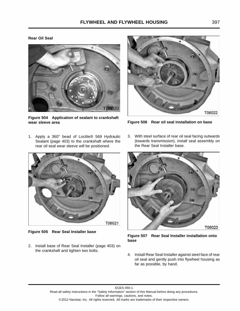
FLYWHEEL AND FLYWHEEL HOUSING 397
Rear Oil Seal
Figure 504 Application of sealant to crankshaftwear sleeve area
1. Apply a 360° bead of Loctite® 569 HydraulicSealant (page 403) to the crankshaft where therear oil seal wear sleeve will be positioned.
Figure 505 Rear Seal Installer base
2. Install base of Rear Seal Installer (page 403) onthe crankshaft and tighten two bolts.
Figure 506 Rear oil seal installation on base
3. With steel surface of rear oil seal facing outwards(towards transmission), install seal assembly onthe Rear Seal Installer base.
Figure 507 Rear Seal Installer installation ontobase
4. Install Rear Seal Installer against steel face of rearoil seal and gently push into flywheel housing asfar as possible, by hand.
EGES-450-1Read all safety instructions in the "Safety Information" section of this Manual before doing any procedures.
Follow all warnings, cautions, and notes.©2012 Navistar, Inc. All rights reserved. All marks are trademarks of their respective owners.

398 FLYWHEEL AND FLYWHEEL HOUSING
Figure 508 Rear oil seal installation
5. Install bearing, washer, and forcing nut on installershaft.
CAUTION: To prevent engine damage, do not use airtools to tighten Rear Seal Installer nut.
6. Tighten forcing nut until rear oil seal installerbottoms out. Rear oil seal assembly will beplaced at the correct depth.
Crankshaft Timing Disk
Figure 509 Crankshaft timing disk alignmentspring pin
CAUTION: To prevent engine damage, timingdisk alignment spring pin must protrude out of thecrankshaft.
Figure 510 Crankshaft timing disk alignmentspring pin (cut-away)
1. Slotted spring pin2. 7.6 mm (0.30 in) max3. Crankshaft timing disk4. Crankshaft
Figure 511 Crankshaft timing disk installation
NOTE: Crankshaft timing disk can be installed witheither side out. Best practice is to install with the partnumber facing outwards.
EGES-450-1Read all safety instructions in the "Safety Information" section of this Manual before doing any procedures.
Follow all warnings, cautions, and notes.©2012 Navistar, Inc. All rights reserved. All marks are trademarks of their respective owners.

FLYWHEEL AND FLYWHEEL HOUSING 399
1. Align index notch of the crankshaft timing disk withcrankshaft timing disk alignment pin.
2. Use a rubber mallet to carefully tap the crankshafttiming disk onto the crankshaft. Tap evenlyaround the crankshaft timing disk to ensure aflush fit against the end of the crankshaft.
NOTE: Rear Seal Installer (page 403) can be used topress the crankshaft timing disk onto the crankshaft.
Flywheel Assembly
Figure 512 Guide pins for flywheel installation
1. Install two guide pins (made locally) in the flywheelmounting bolt holes, 180° from each other.
2. Install flywheel over the guide pins.
3. Install ten M12 x 40 flywheel mounting bolts fingertight.
4. Remove two guide pins and install remaining twoM12 x 40 flywheel mounting bolts finger tight.
Figure 513 Flywheel mounting bolts (typical)
5. Tighten bolts to special torque (page 403).
6. Tighten two remaining rear engine mountingbracket bolts on manual transmission applicationswith 148-tooth ring gears to standard torque (page523).
7. Measure flywheel surface runout (page 393).
EGES-450-1Read all safety instructions in the "Safety Information" section of this Manual before doing any procedures.
Follow all warnings, cautions, and notes.©2012 Navistar, Inc. All rights reserved. All marks are trademarks of their respective owners.

400 FLYWHEEL AND FLYWHEEL HOUSING
Flexplate (Automatic Transmissions)
Allison 2000 Series Transmissions
1. Install two guide pins (made locally) in flexplatemounting bolt holes, 180° from each other.
Figure 514 Adaptor hub, flexplate, and reinforcement ring
1. M12 x 43 bolt (12)2. Reinforcement ring
3. Paint marking index4. Adapter hub AT
5. Flexplate assembly
2. Install adapter hub AT on guide pins.
NOTE: When installed correctly, the ring gear ofthe flexplate is offset (not centered) toward thetransmission.
3. Install flexplate assembly on the guide pins.
CAUTION: To prevent engine damage, make surethe reinforcement ring is installed with the paintmark or XMSN SIDE facing outward (towards thetransmission), otherwise, premature flexplate failuremay occur.
4. Install reinforcement ring on the guide pins withpaint mark (or XMSN SIDE) facing outward.
5. Install ten M12 x 43 flexplate mounting bolts fingertight.
6. Remove guide pins and install remaining two M12x 43 flywheel mounting bolts finger tight.
7. Tighten twelve M12 x 43 flexplate mounting boltsto special torque (page 403).
EGES-450-1Read all safety instructions in the "Safety Information" section of this Manual before doing any procedures.
Follow all warnings, cautions, and notes.©2012 Navistar, Inc. All rights reserved. All marks are trademarks of their respective owners.

FLYWHEEL AND FLYWHEEL HOUSING 401
MD-3000 Series World Transmissions
Figure 515 Flexplate assembly
1. M12 x 45 bolt hole (12)2. Reinforcement ring
3. Crankshaft hub adapter4. M6 bolt (2)
5. Flexplate assembly6. Guide pin (2)
1. Install two guide pins (made locally) in mountingbolt holes, 180° from each other.
CAUTION: To prevent engine damage, make surethe paint mark, part number, or XMSN SIDE on theflexplate is facing outward (towards the transmission).
NOTE: The flexplate assembly is available as acomplete assembled service part.
2. Install flexplate assembly over the guide pins.
NOTE: The following step applies to MDtransmissions only.
3. Install reinforcement ring with part number or logofacing out (towards the transmission).
4. Install ten M12 x 45 flexplate mounting bolts fingertight.
5. Remove guide pins and install remaining two M12x 45 bolts finger tight.
6. Tighten M12 x 45 flexplate mounting bolts tospecial torque (page 403).
NOTE: Flywheel and ring gear are part of the torqueconverter assembly.
EGES-450-1Read all safety instructions in the "Safety Information" section of this Manual before doing any procedures.
Follow all warnings, cautions, and notes.©2012 Navistar, Inc. All rights reserved. All marks are trademarks of their respective owners.
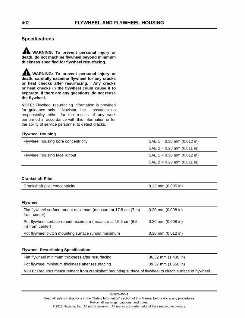
402 FLYWHEEL AND FLYWHEEL HOUSING
Specifications
WARNING: To prevent personal injury ordeath, do not machine flywheel beyond minimumthickness specified for flywheel resurfacing.
WARNING: To prevent personal injury ordeath, carefully examine flywheel for any cracksor heat checks after resurfacing. Any cracksor heat checks in the flywheel could cause it toseparate. If there are any questions, do not reusethe flywheel.
NOTE: Flywheel resurfacing information is providedfor guidance only. Navistar, Inc. assumes noresponsibility either for the results of any workperformed in accordance with this information or forthe ability of service personnel to detect cracks.
Flywheel Housing
SAE 1 = 0.30 mm (0.012 in)Flywheel housing bore concentricity
SAE 2 = 0.28 mm (0.011 in)
SAE 1 = 0.30 mm (0.012 in)Flywheel housing face runout
SAE 2 = 0.28 mm (0.011 in)
Crankshaft Pilot
Crankshaft pilot concentricity 0.13 mm (0.005 in)
Flywheel
Flat flywheel surface runout maximum (measure at 17.8 cm (7 in)from center)
0.20 mm (0.008 in)
Pot flywheel surface runout maximum (measure at 16.5 cm (6.5in) from center)
0.20 mm (0.008 in)
Pot flywheel clutch mounting surface runout maximum 0.30 mm (0.012 in)
Flywheel Resurfacing Specifications
Flat flywheel minimum thickness after resurfacing 36.32 mm (1.430 in)
Pot flywheel minimum thickness after resurfacing 39.37 mm (1.550 in)
NOTE: Requires measurement from crankshaft mounting surface of flywheel to clutch surface of flywheel.
EGES-450-1Read all safety instructions in the "Safety Information" section of this Manual before doing any procedures.
Follow all warnings, cautions, and notes.©2012 Navistar, Inc. All rights reserved. All marks are trademarks of their respective owners.

FLYWHEEL AND FLYWHEEL HOUSING 403
Special Torque
Flexplate mounting bolts, M12 136 N·m (100 lbf·ft)
Flywheel mounting bolts, M12 x 40 136 N·m (100 lbf·ft)
Special Service Tools
Dial indicator set Obtain locally
Guide pins Obtain locally
H-bar puller Obtain locally
Loctite® 569 Hydraulic Sealant Obtain locally
Loctite® 5127 Obtain locally
Rear Seal Installer ZTSE4637
Slide Hammer Puller Set ZTSE1879
EGES-450-1Read all safety instructions in the "Safety Information" section of this Manual before doing any procedures.
Follow all warnings, cautions, and notes.©2012 Navistar, Inc. All rights reserved. All marks are trademarks of their respective owners.

404 FLYWHEEL AND FLYWHEEL HOUSING
EGES-450-1Read all safety instructions in the "Safety Information" section of this Manual before doing any procedures.
Follow all warnings, cautions, and notes.©2012 Navistar, Inc. All rights reserved. All marks are trademarks of their respective owners.
POWER CYLINDERS 405
Table of Contents
Exploded View and Description. . . . . . . . . . . . . . . . . . . . . . . . . . . . . . . . . . . . . . . . . . . . . . . . . . . . . . . . . . . . . . . . . . . . . . . . . . . . . . . . . . . . .407
Removal. . . . . . . . . . . . . . . . . . . . . . . . . . . . . . . . . . . . . . . . . . . . . . . . . . . . . . . . . . . . . . . . . . . . . . . . . . . . . . . . . . . . . . . . . . . . . . . . . . . . . . . . . . . . . . . . .408Piston Cooling Tubes. . . . . . . . . . . . . . . . . . . . . . . . . . . . . . . . . . . . . . . . . . . . . . . . . . . . . . . . . . . . . . . . . . . . . . . . . . . . . . . . . . . . . . . .408Piston Protrusion Measurement – Preliminary Check. . . . . . . . . . . . . . . . . . . . . . . . . . . . . . . . . . . . . . . . . . . . . . . . .408Piston and Connecting Rod Assembly. . . . . . . . . . . . . . . . . . . . . . . . . . . . . . . . . . . . . . . . . . . . . . . . . . . . . . . . . . . . . . . . . . .409Piston Pin and Rings.. . . . . . . . . . . . . . . . . . . . . . . . . . . . . . . . . . . . . . . . . . . . . . . . . . . . . . . . . . . . . . . . . . . . . . . . . . . . . . . . . . . . . . .411Cylinder Sleeve. . . . . . . . . . . . . . . . . . . . . . . . . . . . . . . . . . . . . . . . . . . . . . . . . . . . . . . . . . . . . . . . . . . . . . . . . . . . . . . . . . . . . . . . . . . . . . .412
Cleaning, Inspecting, and Measuring.. . . . . . . . . . . . . . . . . . . . . . . . . . . . . . . . . . . . . . . . . . . . . . . . . . . . . . . . . . . . . . . . . . . . . . . . . . . . . .413Cleaning and Inspecting. . . . . . . . . . . . . . . . . . . . . . . . . . . . . . . . . . . . . . . . . . . . . . . . . . . . . . . . . . . . . . . . . . . . . . . . . . . . . . . . . . . .413Measuring Pistons.. . . . . . . . . . . . . . . . . . . . . . . . . . . . . . . . . . . . . . . . . . . . . . . . . . . . . . . . . . . . . . . . . . . . . . . . . . . . . . . . . . . . . . . . . .414
Top Compression Ring Grooves.. . . . . . . . . . . . . . . . . . . . . . . . . . . . . . . . . . . . . . . . . . . . . . . . . . . . . . . . . . . . . . . .414Intermediate and Oil Control Ring Groove. . . . . . . . . . . . . . . . . . . . . . . . . . . . . . . . . . . . . . . . . . . . . . . . . . . . .415Piston-to-Cylinder Sleeve Running Clearance. . . . . . . . . . . . . . . . . . . . . . . . . . . . . . . . . . . . . . . . . . . . . . . .415
Measuring Piston Rings.. . . . . . . . . . . . . . . . . . . . . . . . . . . . . . . . . . . . . . . . . . . . . . . . . . . . . . . . . . . . . . . . . . . . . . . . . . . . . . . . . . . .416Measuring Piston Pins. . . . . . . . . . . . . . . . . . . . . . . . . . . . . . . . . . . . . . . . . . . . . . . . . . . . . . . . . . . . . . . . . . . . . . . . . . . . . . . . . . . . . .416Measuring and Inspecting Connecting Rods.. . . . . . . . . . . . . . . . . . . . . . . . . . . . . . . . . . . . . . . . . . . . . . . . . . . . . . . . . . .417
Piston Pin Bushing.. . . . . . . . . . . . . . . . . . . . . . . . . . . . . . . . . . . . . . . . . . . . . . . . . . . . . . . . . . . . . . . . . . . . . . . . . . . . . . . .417Connecting Rod Bolt Holes Inspection. . . . . . . . . . . . . . . . . . . . . . . . . . . . . . . . . . . . . . . . . . . . . . . . . . . . . . . . .417Connecting Rod Bearing Bore (Big End). . . . . . . . . . . . . . . . . . . . . . . . . . . . . . . . . . . . . . . . . . . . . . . . . . . . . . .418Connecting Rod Bend and Twist. . . . . . . . . . . . . . . . . . . . . . . . . . . . . . . . . . . . . . . . . . . . . . . . . . . . . . . . . . . . . . . . .418
Bearing Fitting Procedures. . . . . . . . . . . . . . . . . . . . . . . . . . . . . . . . . . . . . . . . . . . . . . . . . . . . . . . . . . . . . . . . . . . . . . . . . . . . . . . . .419Measuring Bearing Running Clearance.. . . . . . . . . . . . . . . . . . . . . . . . . . . . . . . . . . . . . . . . . . . . . . . . . . . . . . . .419Measuring Connecting Rod Side Clearance. . . . . . . . . . . . . . . . . . . . . . . . . . . . . . . . . . . . . . . . . . . . . . . . . . .420
Measuring Cylinder Sleeves. . . . . . . . . . . . . . . . . . . . . . . . . . . . . . . . . . . . . . . . . . . . . . . . . . . . . . . . . . . . . . . . . . . . . . . . . . . . . . . .421Telescoping Gauge Method.. . . . . . . . . . . . . . . . . . . . . . . . . . . . . . . . . . . . . . . . . . . . . . . . . . . . . . . . . . . . . . . . . . . . . .421Dial Bore Gauge Method.. . . . . . . . . . . . . . . . . . . . . . . . . . . . . . . . . . . . . . . . . . . . . . . . . . . . . . . . . . . . . . . . . . . . . . . . . .422Feeler Gauge Method. . . . . . . . . . . . . . . . . . . . . . . . . . . . . . . . . . . . . . . . . . . . . . . . . . . . . . . . . . . . . . . . . . . . . . . . . . . . . .422
Measuring Counterbore Depth. . . . . . . . . . . . . . . . . . . . . . . . . . . . . . . . . . . . . . . . . . . . . . . . . . . . . . . . . . . . . . . . . . . . . . . . . . . . .423Cylinder Liner Height Gauge Method. . . . . . . . . . . . . . . . . . . . . . . . . . . . . . . . . . . . . . . . . . . . . . . . . . . . . . . . . . .423Depth Micrometer Method.. . . . . . . . . . . . . . . . . . . . . . . . . . . . . . . . . . . . . . . . . . . . . . . . . . . . . . . . . . . . . . . . . . . . . . . .423
Measuring Cylinder Sleeve Protrusion.. . . . . . . . . . . . . . . . . . . . . . . . . . . . . . . . . . . . . . . . . . . . . . . . . . . . . . . . . . . . . . . . . .424
Reconditioning. . . . . . . . . . . . . . . . . . . . . . . . . . . . . . . . . . . . . . . . . . . . . . . . . . . . . . . . . . . . . . . . . . . . . . . . . . . . . . . . . . . . . . . . . . . . . . . . . . . . . . . . .426Resurfacing Counterbore. . . . . . . . . . . . . . . . . . . . . . . . . . . . . . . . . . . . . . . . . . . . . . . . . . . . . . . . . . . . . . . . . . . . . . . . . . . . . . . . . . .426
Preparation. . . . . . . . . . . . . . . . . . . . . . . . . . . . . . . . . . . . . . . . . . . . . . . . . . . . . . . . . . . . . . . . . . . . . . . . . . . . . . . . . . . . . . . . . . .426Mounting the Counterbore Reconditioning Tool. . . . . . . . . . . . . . . . . . . . . . . . . . . . . . . . . . . . . . . . . . . . . .427Tool Settings. . . . . . . . . . . . . . . . . . . . . . . . . . . . . . . . . . . . . . . . . . . . . . . . . . . . . . . . . . . . . . . . . . . . . . . . . . . . . . . . . . . . . . . . .428Cutting Counterbore Ledge. . . . . . . . . . . . . . . . . . . . . . . . . . . . . . . . . . . . . . . . . . . . . . . . . . . . . . . . . . . . . . . . . . . . . . .429Tool Care and Maintenance.. . . . . . . . . . . . . . . . . . . . . . . . . . . . . . . . . . . . . . . . . . . . . . . . . . . . . . . . . . . . . . . . . . . . . .429
Installation. . . . . . . . . . . . . . . . . . . . . . . . . . . . . . . . . . . . . . . . . . . . . . . . . . . . . . . . . . . . . . . . . . . . . . . . . . . . . . . . . . . . . . . . . . . . . . . . . . . . . . . . . . . . . .430Cylinder Sleeve. . . . . . . . . . . . . . . . . . . . . . . . . . . . . . . . . . . . . . . . . . . . . . . . . . . . . . . . . . . . . . . . . . . . . . . . . . . . . . . . . . . . . . . . . . . . . . .430Piston Rings.. . . . . . . . . . . . . . . . . . . . . . . . . . . . . . . . . . . . . . . . . . . . . . . . . . . . . . . . . . . . . . . . . . . . . . . . . . . . . . . . . . . . . . . . . . . . . . . . . .431Piston Pin. . . . . . . . . . . . . . . . . . . . . . . . . . . . . . . . . . . . . . . . . . . . . . . . . . . . . . . . . . . . . . . . . . . . . . . . . . . . . . . . . . . . . . . . . . . . . . . . . . . . . .432
EGES-450-1Read all safety instructions in the "Safety Information" section of this Manual before doing any procedures.
Follow all warnings, cautions, and notes.©2012 Navistar, Inc. All rights reserved. All marks are trademarks of their respective owners.

406 POWER CYLINDERS
Piston and Connecting Rod Assembly. . . . . . . . . . . . . . . . . . . . . . . . . . . . . . . . . . . . . . . . . . . . . . . . . . . . . . . . . . . . . . . . . . .433Torque-to-yield Procedure for Connecting Rods.. . . . . . . . . . . . . . . . . . . . . . . . . . . . . . . . . . . . . . . . . . . . .435
Piston Cooling Tubes.. . . . . . . . . . . . . . . . . . . . . . . . . . . . . . . . . . . . . . . . . . . . . . . . . . . . . . . . . . . . . . . . . . . . . . . . . . . . . . . . . . . . . . .436
Engine Run-in Procedure. . . . . . . . . . . . . . . . . . . . . . . . . . . . . . . . . . . . . . . . . . . . . . . . . . . . . . . . . . . . . . . . . . . . . . . . . . . . . . . . . . . . . . . . . . . . .437
Specifications. . . . . . . . . . . . . . . . . . . . . . . . . . . . . . . . . . . . . . . . . . . . . . . . . . . . . . . . . . . . . . . . . . . . . . . . . . . . . . . . . . . . . . . . . . . . . . . . . . . . . . . . . .438
Special Torque.. . . . . . . . . . . . . . . . . . . . . . . . . . . . . . . . . . . . . . . . . . . . . . . . . . . . . . . . . . . . . . . . . . . . . . . . . . . . . . . . . . . . . . . . . . . . . . . . . . . . . . . . .440
Special Service Tools. . . . . . . . . . . . . . . . . . . . . . . . . . . . . . . . . . . . . . . . . . . . . . . . . . . . . . . . . . . . . . . . . . . . . . . . . . . . . . . . . . . . . . . . . . . . . . . . .441
EGES-450-1Read all safety instructions in the "Safety Information" section of this Manual before doing any procedures.
Follow all warnings, cautions, and notes.©2012 Navistar, Inc. All rights reserved. All marks are trademarks of their respective owners.

POWER CYLINDERS 407
Exploded View and Description
Figure 516 Cylinder, piston, rings, and connecting rod (typical)
1. Cylinder sleeve2. Crevice seal ring3. Top compression piston ring4. Intermediate compression piston
ring
5. Oil control piston ring6. Piston pin retainer (2)7. Piston8. Connecting rod cap9. Connecting rod bolt (2)
10. Connecting rod bearing (2)11. Connecting rod12. Piston pin13. Front of engine
Six removable cylinder sleeves, each with a singlecrevice seal ring, are installed in the crankcase.
Pistons are one-piece cast aluminum or one-pieceforged steel and use floating piston pins.
Piston cooling tubes spray oil on the bottom of thepistons for cooling and lubrication.
Three rings are installed on each piston to seal thecombustion chamber and to control oil on the cylinderwalls.
Connecting rods have a fractured surface at theconnecting rod cap bolted joint (big end). These arematch-mated surfaces and are not interchangeable.
EGES-450-1Read all safety instructions in the "Safety Information" section of this Manual before doing any procedures.
Follow all warnings, cautions, and notes.©2012 Navistar, Inc. All rights reserved. All marks are trademarks of their respective owners.

408 POWER CYLINDERS
Removal
GOVERNMENT REGULATION: Enginefluids (oil, fuel, and coolant) may be a hazardto human health and the environment.Handle all fluids and other contaminatedmaterials (e.g. filters, rags) in accordancewith applicable regulations. Recycleor dispose of engine fluids, filters, andother contaminated materials according toapplicable regulations.
WARNING: To prevent personal injury ordeath, read all safety instructions in the “SafetyInformation” section of this manual.
WARNING: To prevent personal injury ordeath, shift transmission to park or neutral, setparking brake, and block wheels before doingdiagnostic or service procedures.
WARNING: To prevent personal injury ordeath, allow engine to cool before working withcomponents.
WARNING: To prevent personal injury ordeath, do not let engine fluids stay on your skin.Clean skin and nails using hand cleaner and washwith soap and water. Wash or discard clothingand rags contaminated with engine fluids.
CAUTION: To prevent engine damage, do not allowconnecting rod or connecting rod cap fractured matingsurfaces to contact any surface other then its matchedfractured surface. Contacting any other surface couldcause misalignment of the mating surface, resulting inconnecting rod bearing and engine failure.
Piston Cooling Tubes
Figure 517 Piston cooling tube (typical)
1. Piston cooling tube assembly (6)2. Piston cooling jet bolt (6)3. Crankcase piston cooling tube mounting pad (6)
NOTE: The crankshaft may need to be rotated toaccess some piston cooling tubes.
1. Remove and discard six piston cooling jetbolts, securing the piston cooling tubes to thecrankcase.
2. Remove piston cooling tubes and discard sealingrings.
Piston Protrusion Measurement – PreliminaryCheck
NOTE: Evaluate piston protrusion before removingany piston and connecting rod assemblies. This helpsidentify bent, twisted, or worn conditions.
1. Install cylinder Sleeve Protrusion Hold DownClamps (page 441) with 10.9 or higher gradebolts finger tight. See Measuring Cylinder SleeveProtrusion (page 424) for proper installationprocedures.
2. Tighten cylinder sleeve holding adaptor bolts to 55N·m (40 lbf·ft).
3. Tighten cylinder sleeve holding adaptor bolts to110 N·m (80 lbf·ft).
4. Place Cylinder Liner Height Gauge (page 441) oncrankcase deck.
EGES-450-1Read all safety instructions in the "Safety Information" section of this Manual before doing any procedures.
Follow all warnings, cautions, and notes.©2012 Navistar, Inc. All rights reserved. All marks are trademarks of their respective owners.

POWER CYLINDERS 409
5. Place Cylinder Liner Height Gauge indicator tip oncrankcase deck and zero dial indicator.
6. Bring piston to be measured to Top Dead Center(TDC).
7. Depress indicator plunger and slide CylinderLiner Height Gauge to allow indicator tip to reston piston top flat surface, as close to area abovewrist pin as possible.
8. Hold Cylinder Liner Height Gauge and slightly barengine fore and aft to measure maximum pistonprotrusion above crankcase deck. Compareto piston protrusion above crankcase top deckSpecification (page 438).
Piston and Connecting Rod Assembly
CAUTION: To prevent engine damage, do not allowconnecting rod or connecting rod cap fractured matingsurfaces to contact any surface other then its matchedfractured surface. Contacting any other surface couldcause misalignment of the mating surface, resulting inconnecting rod bearing and engine failure.
NOTE: If a carbon ridge has developed on the top ofthe cylinder sleeve, remove the cylinder sleeve andpiston as an assembly and then remove the pistonfrom the bottom of the cylinder sleeve.
Figure 518 Connecting rod bolt removal
1. Loosen both connecting rod bolts. Leave boltsattached to the connecting rod.
2. Push connecting rod bolts down to separateconnecting rod from crankshaft journal.
Figure 519 Connecting rod cap and boltsremoval
3. Remove connecting rod cap and bolts.
EGES-450-1Read all safety instructions in the "Safety Information" section of this Manual before doing any procedures.
Follow all warnings, cautions, and notes.©2012 Navistar, Inc. All rights reserved. All marks are trademarks of their respective owners.

410 POWER CYLINDERS
Figure 520 Piston and connecting rod assemblyremoval
CAUTION: To prevent engine damage, do not pushon the connecting rod fractured surface.
4. Push the piston out of the cylinder sleeve usingthe butt end of a plastic or wooden hammer handleor a non-marring punch. Do not push on theconnecting rod fractured surface.
Figure 521 Piston and connecting rod assemblyremoval (typical)
5. When the piston rings are free of the cylindersleeve, remove the assembly from the top of thecrankcase.
CAUTION: To prevent engine damage, usepermanent marker to identify internal enginecomponents and their orientation. Do not use paintor temporary markers.
6. Mark each piston, connecting rod, and cap withits cylinder number. Also mark the front of eachpiston as it was installed in the engine.
7. Install each connecting rod cap on its matchedconnecting rod and finger tighten connectingrod cap bolts to protect connecting rod fracturedsurface.
NOTE: Each piston, connecting rod, and cylindersleeve can be removed together without removing thepiston from the cylinder sleeve. Remove the cylinderhead and connecting rod cap and then carefully drivethe cylinder sleeve straight out using a wood blockand a hammer. Be careful not to damage the pistoncooling tubes. Maintain the power cylinder packageundisturbed while replacing sleeve O-rings.
EGES-450-1Read all safety instructions in the "Safety Information" section of this Manual before doing any procedures.
Follow all warnings, cautions, and notes.©2012 Navistar, Inc. All rights reserved. All marks are trademarks of their respective owners.

POWER CYLINDERS 411
Piston Pin and Rings
Figure 522 Piston pin retaining ring removal(typical)
WARNING: To prevent personal injury ordeath, wear safety glasses with side shields.
1. Use pliers to contract the piston pin retainingrings. Remove two piston pin retaining rings.
Figure 523 Remove piston pin (typical)
2. Push the piston pin out of the piston andconnecting rod, by hand.
CAUTION: To prevent engine damage, use care to notallow piston pins to contact other pins or other objects.Store individually.
3. Separate the piston from the connecting rod.
4. Mark the front of the piston pin with its cylindernumber.
Figure 524 Piston ring removal (typical)
5. Use a piston ring expander (page 441) to expandeach piston ring and remove rings from thepistons.
EGES-450-1Read all safety instructions in the "Safety Information" section of this Manual before doing any procedures.
Follow all warnings, cautions, and notes.©2012 Navistar, Inc. All rights reserved. All marks are trademarks of their respective owners.

412 POWER CYLINDERS
Cylinder Sleeve
Figure 525 Cylinder sleeve removal
CAUTION: To prevent engine damage, beforeinstalling the Cylinder Sleeve Puller in each cylinder,rotate the crankshaft so the crankshaft journal is atthe bottom (low point) of its travel. This can preventdamage to the journal during puller installation.
CAUTION: To prevent engine damage, be careful notto damage the piston cooling tubes when installing orremoving the Cylinder Sleeve Puller.
NOTE: When removing the sleeve from the puller,mark the sleeve with its cylinder number. Also markthe sleeve position in the crankcase for inspection andassembly.
1. If the cylinder sleeve is to be reused, mark theposition of the cylinder sleeve on the crankcasedeck for reference during installation.
2. Position the Cylinder Sleeve Puller (page 441) inthe cylinder sleeve and spread the lifting jaws sothe tangs grip the bottom of the sleeve.
3. With the Cylinder Sleeve Puller lifting bridgesquarely on the crankcase deck surface, turn thecenter shaft bolt to pull the cylinder sleeve out ofthe crankcase.
4. Lift sleeve and puller out of the crankcase.
5. Use a pick to remove the crevice seal ring at thelower counterbore area of each cylinder sleeve.Discard crevice seal ring.
EGES-450-1Read all safety instructions in the "Safety Information" section of this Manual before doing any procedures.
Follow all warnings, cautions, and notes.©2012 Navistar, Inc. All rights reserved. All marks are trademarks of their respective owners.

POWER CYLINDERS 413
Cleaning, Inspecting, andMeasuringCleaning and Inspecting
CAUTION: To prevent engine damage, do not usecaustic solvent, wire brushes, or media blasting toclean pistons.
1. Soak pistons in a soap and water solution andclean with a non-metallic brush.
2. Scrub piston ring grooves thoroughly. Make surethe oil drain holes in the oil ring grooves are notblocked.
3. Inspect pistons for cracks, excessive wear, andworn ring lands. Replace damaged pistons ifrequired.
CAUTION: To prevent engine damage, do not cleanthe fractured mating surfaces of connecting rods.
4. Use a suitable solvent and a non-metallic brush toclean the connecting rods and caps, piston rings,pins, and cylinder sleeves.
5. Inspect piston pins for damage, nicks, andexcessive wear. Replace piston pins if required.
6. Clean the connecting rod bolt holes and threads.Do not tap the connecting rod bolt holes. Inspectthe finished surface of the connecting rod bearingbore for nicks, burrs, and scoring. Replace theconnecting rod if required.
7. Inspect cylinder sleeves for excessive wear,scoring, and cracks. Replace damaged cylindersleeves if required.
8. Clean crankcase crevice seal ring bore area ofany scale, deposits, or sealant.
EGES-450-1Read all safety instructions in the "Safety Information" section of this Manual before doing any procedures.
Follow all warnings, cautions, and notes.©2012 Navistar, Inc. All rights reserved. All marks are trademarks of their respective owners.

414 POWER CYLINDERS
Measuring Pistons
Top Compression Ring Grooves
Piston Ring Gauge Pin Selection
Engine Ring / Groove Type Gauge Pin Diameter
MaxxForce® DT Top / keystone cross section 2.885 mm (0.1136 in)
MaxxForce® 9 and 10 Top / keystone cross section 2.70 mm (0.1063 in)
Figure 526 Measuring piston ring groove (top /keystone cross section)
1. Install Piston Gauge Pins (page 441) in the topcompression ring groove. Make sure the gaugepins are parallel.
2. With pistons at room temperature 20 °C (68 °F),measure the diameter of the piston over the gaugepins using an outside micrometer (page 441).
3. If the top compression ring groove widthmeasurement exceeds Specification (page 438),replace the piston.
EGES-450-1Read all safety instructions in the "Safety Information" section of this Manual before doing any procedures.
Follow all warnings, cautions, and notes.©2012 Navistar, Inc. All rights reserved. All marks are trademarks of their respective owners.

POWER CYLINDERS 415
Intermediate and Oil Control Ring Groove
Figure 527 Measuring ring groove (typical)
1. Place the edge of a new intermediatecompression piston ring in the middle piston ringgroove. Roll the intermediate compression pistonring all the way around the piston ring groove toensure the ring is free in its groove.
2. With the edge of the intermediate compressionpiston ring in the piston intermediate compressionpiston ring groove, use a feeler gauge (page441) to measure clearance between the ring andgroove.
If the intermediate compression ring sideclearance exceeds Specification (page 438),replace the piston.
3. Place the edge of a new oil control piston ringin the oil control ring groove. Roll the oil controlpiston ring all the way around the piston to ensurethe ring is free in its groove.
4. With the edge of the oil control piston ring in thepiston oil ring groove, use a feeler gauge (page441) to measure clearance between the ring andgroove.
If the oil control ring side clearance exceedsSpecification (page 438), replace the piston.
Piston-to-Cylinder Sleeve Running Clearance
Figure 528 Measuring piston skirt diameter(typical)
1. With pistons at room temperature 20 °C (68 °F),use an outside micrometer (page 441) to measurepiston skirt diameter. Place micrometer 90° fromthe piston pin bore.
• For MaxxForce® DT aluminum pistons, takeskirt diameter measurement 22 mm (0.87 in)from the bottom of the piston skirt.
• For MaxxForce® 9 and 10 steel pistons, takeskirt diameter measurement 12 mm (0.47 in)from the bottom of the piston skirt.
2. Subtract the piston skirt diameter from the insidediameter of the cylinder sleeve. See MeasuringCylinder Sleeves (page 421). The result is therunning clearance between the piston and thecylinder sleeve.
NOTE: Piston to Cylinder Sleeve RunningClearance = Cylinder Sleeve Inside Diameter– Piston Skirt Diameter
3. If piston to cylinder sleeve running clearanceis not within Specification (page 438), recheckpiston and cylinder sleeve measurements andspecifications. Replace the part that is out ofspecification.
EGES-450-1Read all safety instructions in the "Safety Information" section of this Manual before doing any procedures.
Follow all warnings, cautions, and notes.©2012 Navistar, Inc. All rights reserved. All marks are trademarks of their respective owners.

416 POWER CYLINDERS
Measuring Piston Rings
Figure 529 Measuring piston ring end gap
NOTE: The top of a piston can be used to pushpiston ring down in the cylinder sleeve to insure ringis squarely positioned in the sleeve.
1. Install each piston ring into its cylinder bore. Makesure the ring is perpendicular to the cylinder wall.If measuring used rings, install ring just below thetop of piston ring travel.
2. Use a feeler gauge (page 441) to measure the endgap between the ends of each piston ring.
Discard any piston ring that does not meetSpecifications (page 439).
NOTE: If replacement of the cylinder sleeve isrequired, replace the cylinder sleeve and piston ringsas a set.
NOTE: If any piston ring is replaced, replace all pistonrings and the cylinder sleeve for that cylinder.
Measuring Piston Pins
Figure 530 Measuring piston pin
1. Use an outside micrometer (page 441) tomeasure the diameter of the each piston pinat two locations.
2. If the diameter of any piston pin is less thanminimum Specification (page 439), replace thepiston pin.
3. With pistons at room temperature 20° C (68° F),measure each piston pin bore.
4. Calculate piston pin clearance. Subtract thediameter of the piston pin from the inside diameterof the piston pin bore.
NOTE: Piston Pin Clearance in Piston = PistonPin Bore Inside Diameter – Piston Pin Diameter
5. If piston pin clearance in piston exceedsSpecification (page 439), replace the piston.
EGES-450-1Read all safety instructions in the "Safety Information" section of this Manual before doing any procedures.
Follow all warnings, cautions, and notes.©2012 Navistar, Inc. All rights reserved. All marks are trademarks of their respective owners.
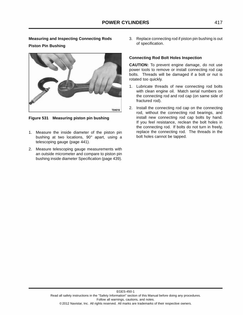
POWER CYLINDERS 417
Measuring and Inspecting Connecting Rods
Piston Pin Bushing
Figure 531 Measuring piston pin bushing
1. Measure the inside diameter of the piston pinbushing at two locations, 90° apart, using atelescoping gauge (page 441).
2. Measure telescoping gauge measurements withan outside micrometer and compare to piston pinbushing inside diameter Specification (page 439).
3. Replace connecting rod if piston pin bushing is outof specification.
Connecting Rod Bolt Holes Inspection
CAUTION: To prevent engine damage, do not usepower tools to remove or install connecting rod capbolts. Threads will be damaged if a bolt or nut isrotated too quickly.
1. Lubricate threads of new connecting rod boltswith clean engine oil. Match serial numbers onthe connecting rod and rod cap (on same side offractured rod).
2. Install the connecting rod cap on the connectingrod, without the connecting rod bearings, andinstall new connecting rod cap bolts by hand.If you feel resistance, reclean the bolt holes inthe connecting rod. If bolts do not turn in freely,replace the connecting rod. The threads in thebolt holes cannot be tapped.
EGES-450-1Read all safety instructions in the "Safety Information" section of this Manual before doing any procedures.
Follow all warnings, cautions, and notes.©2012 Navistar, Inc. All rights reserved. All marks are trademarks of their respective owners.

418 POWER CYLINDERS
Connecting Rod Bearing Bore (Big End)
Figure 532 Measuring connecting rod bearingbore out-of-round
NOTE: If performing bearing fit procedure, do nottorque-to-yield connecting rod cap bolts. Tightenconnecting rod cap bolts to 109 N·m (80 lbf·ft).
1. Measure the inside diameter of each connectingrod bearing bore at three locations 60° apart,using an inside micrometer (page 441).
If the difference between measurement B andthe average of measurements A and C exceedsout-of-round Specification (page 438), replacethe connecting rod.
Figure 533 Measuring connecting rod bearingbore taper
2. Use a telescoping gauge and an outsidemicrometer (page 441), measure the insidediameter of the connecting rod bearing bore atthe edge of each side of the bore.
If the difference between the two measurementsexceeds bore taper Specification (page 438),replace the connecting rod assembly.
Connecting Rod Bend and Twist
Engine component wear patterns can often beidentified and used to diagnose problems. Somecommon examples of connecting rod wear patternsinclude:
• A shiny surface on the edge of the piston pin boreusually indicates that a connecting rod is bentor a piston pin hole is not positioned properly inrelation to the piston skirt and piston ring grooves.
• Abnormal wear on the connecting rod bearingmay indicate that a connecting rod is bent or thebearing bore is excessively tapered.
• A twisted connecting rod will not create aneasily identifiable wear pattern, althoughseverely twisted connecting rods will disturbthe action of the entire piston and connecting rodassembly and may be the cause of excessive oilconsumption.
If any of these conditions exist, use a suitablealignment fixture to check the connecting rod forbends and twists. Follow the instructions of thealignment fixture manufacturer. If bend or twistexceeds Specification (page 438), replace theconnecting rod.
EGES-450-1Read all safety instructions in the "Safety Information" section of this Manual before doing any procedures.
Follow all warnings, cautions, and notes.©2012 Navistar, Inc. All rights reserved. All marks are trademarks of their respective owners.

POWER CYLINDERS 419
Bearing Fitting Procedures
CAUTION: To prevent engine damage, do not attemptto reduce journal-to-bearing running clearance byreworking the connecting rod bearing cap or thebearings. Grind the crankshaft to the next availableunder size or replace the crankshaft.
Figure 534 Effects of bearing crush
1. Diameter at open ends after bearing crush load2. Diameter at open ends before bearing crush load
NOTE: Connecting rod bearings must fit tightly in theconnecting rod bore. When bearings are insertedin the connecting rod and cap, they protrude slightlyabove the parting surface. This protrusion is requiredto achieve bearing crush. Bearing crush forces theends inward at the parting line when a load is appliedby tightening the bolts. Some snap may be lost innormal use, but bearing replacement is not requiredbecause of a nominal loss of snap.
When the connecting rod bearing is installed and theconnecting rod cap bolts are tightened, the bearing iscompressed, ensuring a positive contact between thebackside of the bearing and the machined surface ofthe connecting rod bore.
Measuring Bearing Running Clearance
1. Install new bearings in the connecting rod andcap.
CAUTION: To prevent engine damage, correct matingof connecting rod and cap are required to preventdamage to connecting rod fractured surface.
CAUTION: To prevent engine damage, do nottorque-to-yield connecting rod cap bolts while doingthis measurement procedure.
CAUTION: To prevent engine damage, whentorquing connecting rod bolts use a calibrated torquewrench. Correct torque of connecting rod cap bolts isimportant.
2. Match serial numbers on the connecting rod androd cap (on same side of fractured rod) and installthe connecting rod and cap on the crankshaft.See Piston and Connecting Rod Assembly (page433).
3. Remove the connecting rod cap. Wipe the oilfrom the face of the bearings in the cap and theexposed portion of the crankshaft.
4. Place a piece of undamaged Plastigage acrossthe full width of the connecting rod bearing, about6 mm (0.25 in) from the center of the connectingrod cap.
5. Install the connecting rod cap and tighten the boltsto 109 N·m (80 lbf·ft).
NOTE: Do not turn the crankshaft. This will smear thePlastigage making it unusable.
EGES-450-1Read all safety instructions in the "Safety Information" section of this Manual before doing any procedures.
Follow all warnings, cautions, and notes.©2012 Navistar, Inc. All rights reserved. All marks are trademarks of their respective owners.

420 POWER CYLINDERS
Figure 535 Measuring with Plastigage
6. Remove the connecting rod cap. The Plastigagematerial will adhere to either the connecting rodbearing or the crankshaft. Do not remove thePlastigage.
7. Use the Plastigage paper scale to measurethe widest point of the flattened material.The numbers in the graduated marks on thewrapper scale indicate the running clearance inthousandths of an inch or millimeters.
8. Compare Plastigage measurements withconnecting rod bearing running clearanceSpecification (page 438).
NOTE: If running clearance is not withinspecifications, grinding the crankshaft and usingundersized bearings may be necessary. Re-measurerunning clearance before condemning the crankshaft.
9. Remove the Plastigage material. Repeat the testfor each connecting rod bearing.
Measuring Connecting Rod Side Clearance
Figure 536 Measuring connecting rod sideclearance
1. Insert a feeler gauge (page 441) between theconnecting rod and crankshaft journal.
2. If the connecting rod side clearance is not inSpecification (page 438), replace the connectingrod.
NOTE: If there is too little side clearance, theconnecting rod may be damaged or the bearingmay be out of position. If there is too much clearance,the connecting rod or crankshaft may be damaged.
EGES-450-1Read all safety instructions in the "Safety Information" section of this Manual before doing any procedures.
Follow all warnings, cautions, and notes.©2012 Navistar, Inc. All rights reserved. All marks are trademarks of their respective owners.

POWER CYLINDERS 421
Measuring Cylinder Sleeves
NOTE: If replacement of the cylinder sleeve isrequired, replace the cylinder sleeve and piston ringsas a set.
Measure cylinder sleeve wear (taper), using one of thefollowing methods:
Telescoping Gauge Method
1. Measure the inside diameter of each cylindersleeve at two locations 90° apart just below thetop of piston ring travel and again just abovethe bottom area of piston ring travel using atelescoping gauge (page 441) and an outsidemicrometer (page 441).
Figure 537 Measuring cylinder sleeve taper
2. Install telescoping gauge plungers perpendicularto the cylinder sleeve center line. Unlock and fit
plungers to the cylinder sleeve. Lock and thenrotate gauge out of cylinder sleeve.
Figure 538 Measuring telescoping gauge
3. Measure the telescoping gauge with an outsidemicrometer (page 441).
4. Calculate cylinder sleeve taper by subtracting theaverage of the lower reading from the average ofthe higher reading.
5. If cylinder sleeve taper exceeds Specification(page 440), replace the cylinder sleeve andpiston rings.
6. Repeat steps 1 through 5 for all six cylindersleeves.
EGES-450-1Read all safety instructions in the "Safety Information" section of this Manual before doing any procedures.
Follow all warnings, cautions, and notes.©2012 Navistar, Inc. All rights reserved. All marks are trademarks of their respective owners.

422 POWER CYLINDERS
Dial Bore Gauge Method
Figure 539 Measuring cylinder sleeve taper
1. Measure the inside diameter of each cylindersleeve at two locations 90° apart just below thetop of piston ring travel and again just above thebottom area of piston ring travel using a cylinderbore gauge (page 441).
2. Calculate cylinder sleeve taper by subtracting theaverage of the lower reading from the average ofthe higher reading.
3. If cylinder sleeve taper exceeds Specification(page 440), replace the cylinder sleeve andpiston rings.
Feeler Gauge Method
Figure 540 Measuring cylinder sleeve pistonring end gap
1. Install the top compression ring squarely into itscylinder bore just below the top of piston ringtravel. Make sure the ring is perpendicular to thecylinder wall.
2. Use a feeler gauge (page 441) to measure the ringend gap.
3. Move the top compression ring squarely on thebottom of the piston ring travel area.
4. Measure piston ring end gap using a feeler gauge.
NOTE: Every increase of 0.07 mm (0.003 in) betweenthe measurements equals a 0.0223 mm (0.0009 in)increase in cylinder sleeve inside diameter.
5. If the cylinder sleeve is worn beyond Specification(page 440), replace the cylinder sleeve and pistonrings.
EGES-450-1Read all safety instructions in the "Safety Information" section of this Manual before doing any procedures.
Follow all warnings, cautions, and notes.©2012 Navistar, Inc. All rights reserved. All marks are trademarks of their respective owners.

POWER CYLINDERS 423
Measuring Counterbore Depth
NOTE: Remove any existing shims and cleancounterbore surface before measuring counterboredepth. Inspect each crankcase counterbore forcracks.
Use one of the following methods to measure depth ofeach crankcase counterbore:
Cylinder Liner Height Gauge Method
Figure 541 Measuring counterbore depth
1. Crankcase deck surface2. Counterbore ledge
1. Place the indicator tip of a Cylinder Liner HeightGauge (page 441) on the crankcase deck surfaceand zero the dial indicator.
2. Move the gauge indicator tip to the counterboreledge and measure the counterbore depth.
3. Measure counterbore depth at four evenly spacedlocations around each counterbore ledge.
4. If the maximum variation between the fourmeasurements exceeds Specification (page440), resurface the counterbore.
Depth Micrometer Method
Figure 542 Measuring counterbore depth
1. Place a depth micrometer (page 441) on thecrankcase deck surface and measure thedistance to the counterbore ledge (counterboredepth).
2. Measure counterbore depth at four evenly spacedlocations around the counterbore ledge.
3. If the maximum variation between the fourmeasurements exceeds Specification (page440), resurface the counterbore.
EGES-450-1Read all safety instructions in the "Safety Information" section of this Manual before doing any procedures.
Follow all warnings, cautions, and notes.©2012 Navistar, Inc. All rights reserved. All marks are trademarks of their respective owners.

424 POWER CYLINDERS
Measuring Cylinder Sleeve Protrusion
Figure 543 Cylinder sleeve clamping (cut-away)
1. Cylinder sleeve fire dam (highest point on cylindersleeve)
2. Cylinder Sleeve Protrusion Hold Down Clamp3. Cylinder sleeve holding adapter bolt4. Crankcase5. Cylinder sleeve6. Shim pack (if required)
CAUTION: To prevent engine damage, do not applyholding adapters to the "fire dam" ridge of the cylindersleeve. Clamping forces should not be applied to thisridge as internal cracking could develop adjacent tothe shim land.
1. Clean the cylinder sleeve, cylinder sleeve crevicebore, and crankcase counterbore surfaces.
2. Install the cylinder sleeve with proper orientationin the proper cylinder bore without the crevice sealring.
Figure 544 Installing Sleeve Protrusion HoldDown Clamps
3. Install Cylinder Sleeve Protrusion Hold DownClamps (page 441) with 10.9 or higher gradebolts and finger tighten. Locate clamps on thecylinder sleeve flange as indicated in (Figure543) and (Figure 544).
CAUTION: To prevent engine damage, do nottorque-to-yield hold down clamp bolts.
4. Tighten supplied hold down clamp bolts to 55 N·m(40 lbf·ft).
5. Tighten supplied hold down clamp bolts to 110N·m (80 lbf·ft).
EGES-450-1Read all safety instructions in the "Safety Information" section of this Manual before doing any procedures.
Follow all warnings, cautions, and notes.©2012 Navistar, Inc. All rights reserved. All marks are trademarks of their respective owners.

POWER CYLINDERS 425
Figure 545 Measuring cylinder sleeve protrusion
6. Place the indicator tip of a Cylinder Liner HeightGauge (page 441) on the cylinder sleeve flangeand zero the dial indicator.
7. Move the Cylinder Liner Height Gauge until theindicator tip slides off the flange to the surface ofthe crankcase.
Figure 546 Cylinder sleeve protrusion(cut-away)
1. Cylinder sleeve protrusion2. Top surface of crankcase3. Cylinder sleeve flange4. Shim5. Counterbore depth
8. Measure cylinder sleeve protrusion at fourlocations evenly spaced around the cylindersleeve. Average the four readings to determinecylinder sleeve protrusion.
If cylinder sleeve protrusion does not meetSpecification (page 440), determine shimthickness necessary to meet the cylinder sleeveprotrusion specification.
9. Remove the cylinder sleeve and install thenecessary cylinder sleeve shims.
10. Repeat steps 2 through 8 for all six cylinders.
11. If the difference in cylinder sleeve protrusionbetween all six sleeves is greater than 0.03 mm(0.001 in), remove the highest cylinder sleeve andinstall the correct shim or resurface counterbore.Measure cylinder sleeve protrusion again.
EGES-450-1Read all safety instructions in the "Safety Information" section of this Manual before doing any procedures.
Follow all warnings, cautions, and notes.©2012 Navistar, Inc. All rights reserved. All marks are trademarks of their respective owners.

426 POWER CYLINDERS
ReconditioningResurfacing Counterbore
Figure 547 Counterbore Reconditioning Tool Kit
1. Base assembly2. Stop collar3. Cutter head assembly4. Carbide cutting screw (spare)
5. Carbide cutting insert (spare)6. T-handle allen wrench7. Torx® wrench8. Bolt spacers (2)
9. Shims (4)10. Cutter foam plugs (3)
To ensure optimal counterbore ledge machiningresults, obtain a Counterbore Reconditioning Tool Kit(page 441) and do the following:
• Inspect all counterbore ledges and alwaysmachine worst condition ledge first and followin succession.
• Inspect cutter head integrity prior to setting toolassembly. Ensure tool is free of sharp edges,grooves, and burrs.
• Ensure final setting remains intact for allremaining counterbore ledges after final cuttingdepth is established.
Preparation
1. Remove cylinder head, connecting rods, pistons,and all cylinder liners for counterbore ledgesrequiring machining.
2. Block all exposed oil gallery holes to preventdebris from entering lubrication system.
3. Clean crankcase deck surface and ensure surfaceis free of gasket material. Inspect surface for nicksor burrs to ensure proper seating of tool assembly.Repair as required.
EGES-450-1Read all safety instructions in the "Safety Information" section of this Manual before doing any procedures.
Follow all warnings, cautions, and notes.©2012 Navistar, Inc. All rights reserved. All marks are trademarks of their respective owners.

POWER CYLINDERS 427
Mounting the Counterbore Reconditioning Tool
Figure 548 Mounting counterbore cutting tool
1. Insert foam plugs 1/2” deep into cylinder housingto be machined and adjacent cylinder housings.This prevents debris from entering the engine.
2. Mount the counterbore cutting tool to thecrankcase for cylinder bore to be machined.The tool must not bind.
Figure 549 Aligning counterbore tool
3. Align the holes of the base assembly to thecrankcase mounting hole.
Figure 550 Inserting bolt spacers and head bolts
4. Place one bolt spacer onto each of the twohead bolts. Insert head bolts through the baseassembly and into the crankcase. Finger tightenboth bolts.
EGES-450-1Read all safety instructions in the "Safety Information" section of this Manual before doing any procedures.
Follow all warnings, cautions, and notes.©2012 Navistar, Inc. All rights reserved. All marks are trademarks of their respective owners.

428 POWER CYLINDERS
Figure 551 Centering cutter head
5. Turn the cutter head assembly 1 to 2 revolutionscounter clockwise to center the cutter head. A“position” arrow is located on the base assemblyfor directional reference.
6. Tighten two cylinder head bolts to 40 N·m (30lbf·ft).
Tool Settings
Figure 552 Installing shims
NOTE: See Cylinder Sleeve Specifications (page440) for allowable counterbore depths.
1. Determine required depth of cut. Select shims toachieve desired cut depth. Install shims under thestop collar.
Figure 553 Locking the stop collar
EGES-450-1Read all safety instructions in the "Safety Information" section of this Manual before doing any procedures.
Follow all warnings, cautions, and notes.©2012 Navistar, Inc. All rights reserved. All marks are trademarks of their respective owners.
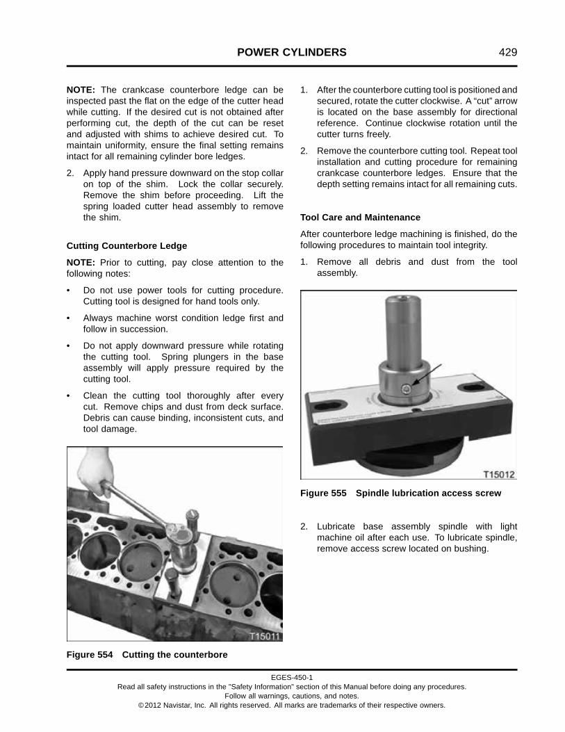
POWER CYLINDERS 429
NOTE: The crankcase counterbore ledge can beinspected past the flat on the edge of the cutter headwhile cutting. If the desired cut is not obtained afterperforming cut, the depth of the cut can be resetand adjusted with shims to achieve desired cut. Tomaintain uniformity, ensure the final setting remainsintact for all remaining cylinder bore ledges.
2. Apply hand pressure downward on the stop collaron top of the shim. Lock the collar securely.Remove the shim before proceeding. Lift thespring loaded cutter head assembly to removethe shim.
Cutting Counterbore Ledge
NOTE: Prior to cutting, pay close attention to thefollowing notes:
• Do not use power tools for cutting procedure.Cutting tool is designed for hand tools only.
• Always machine worst condition ledge first andfollow in succession.
• Do not apply downward pressure while rotatingthe cutting tool. Spring plungers in the baseassembly will apply pressure required by thecutting tool.
• Clean the cutting tool thoroughly after everycut. Remove chips and dust from deck surface.Debris can cause binding, inconsistent cuts, andtool damage.
Figure 554 Cutting the counterbore
1. After the counterbore cutting tool is positioned andsecured, rotate the cutter clockwise. A “cut” arrowis located on the base assembly for directionalreference. Continue clockwise rotation until thecutter turns freely.
2. Remove the counterbore cutting tool. Repeat toolinstallation and cutting procedure for remainingcrankcase counterbore ledges. Ensure that thedepth setting remains intact for all remaining cuts.
Tool Care and Maintenance
After counterbore ledge machining is finished, do thefollowing procedures to maintain tool integrity.
1. Remove all debris and dust from the toolassembly.
Figure 555 Spindle lubrication access screw
2. Lubricate base assembly spindle with lightmachine oil after each use. To lubricate spindle,remove access screw located on bushing.
EGES-450-1Read all safety instructions in the "Safety Information" section of this Manual before doing any procedures.
Follow all warnings, cautions, and notes.©2012 Navistar, Inc. All rights reserved. All marks are trademarks of their respective owners.

430 POWER CYLINDERS
InstallationCylinder Sleeve
CAUTION: To prevent engine damage, if any pistonring or cylinder sleeve is replaced, replace thatcylinder sleeve and piston rings as a set.
NOTE: If required, install appropriate shim(s) in eachcrankcase counterbore based on counterbore depthmeasurements (page 423).
1. If required, install shim(s) in each crankcasecounterbore to bring cylinder sleeve protrusionwithin Specification (page 440).
Figure 556 Cylinder sleeve and crevice seal ring
NOTE: Each cylinder sleeve has one crevice seal ring.
2. A new cylinder sleeve will come kitted with a newcrevice seal ring. If reinstalling a used cylindersleeve, a new crevice seal ring must be used. Inthis case, lightly lubricate the new crevice seal ringwith clean engine oil and install in cylinder sleevegroove.
3. Apply clean engine oil to the lower crankcasecounterbore and crevice seal ring bore.
Figure 557 Cylinder sleeve installation
4. Carefully install each cylinder sleeve in itscrankcase counterbore. If a new cylinder sleeveis installed, it can be installed without regardto orientation. If cylinder sleeves are re-used,however, each sleeve should be installed backinto its original counterbore (cylinder number)and clocked so that camside or front-of-enginemark is in the same engine orientation as prior toremoval.
5. After installation, measure cylinder sleeveprotrusion (page 424).
6. Measure cylinder sleeve protrusion at fourlocations evenly spaced around each cylindersleeve. If the difference of the four measurementsfor any one cylinder is greater than (0.001 in),check for an improperly aligned crevice seal ringand re-measure protrusion.
Average the four measurements and checkcylinder sleeve protrusion Specification (page440). If required, determine shim thicknessnecessary to meet the cylinder sleeve protrusionspecification.
EGES-450-1Read all safety instructions in the "Safety Information" section of this Manual before doing any procedures.
Follow all warnings, cautions, and notes.©2012 Navistar, Inc. All rights reserved. All marks are trademarks of their respective owners.

POWER CYLINDERS 431
Piston Rings
CAUTION: To prevent engine damage, if any pistonring or cylinder sleeve is replaced, replace thatcylinder sleeve and piston rings as a set.
Figure 558 Oil control piston ring
1. Oil control ring2. Ring expander coil, paint stripe
NOTE: The orange paint stripe on the ring expandercoil must align and show through the oil ring gap.
Figure 559 Installing piston rings (typical)
NOTE: Make sure the top side of both compressionrings (marked with a dot) are facing up. The oil controlpiston ring may be installed with either side facing up,if new.
1. Install rings on each piston using a piston ringexpander (page 441). Expand the oil controlpiston ring enough to fit it over the piston crownand install in the lower ring groove of the piston.
2. Expand the intermediate compression piston ringand install in the middle piston ring groove.
3. Expand the top compression piston ring andinstall in the top piston ring groove.
EGES-450-1Read all safety instructions in the "Safety Information" section of this Manual before doing any procedures.
Follow all warnings, cautions, and notes.©2012 Navistar, Inc. All rights reserved. All marks are trademarks of their respective owners.
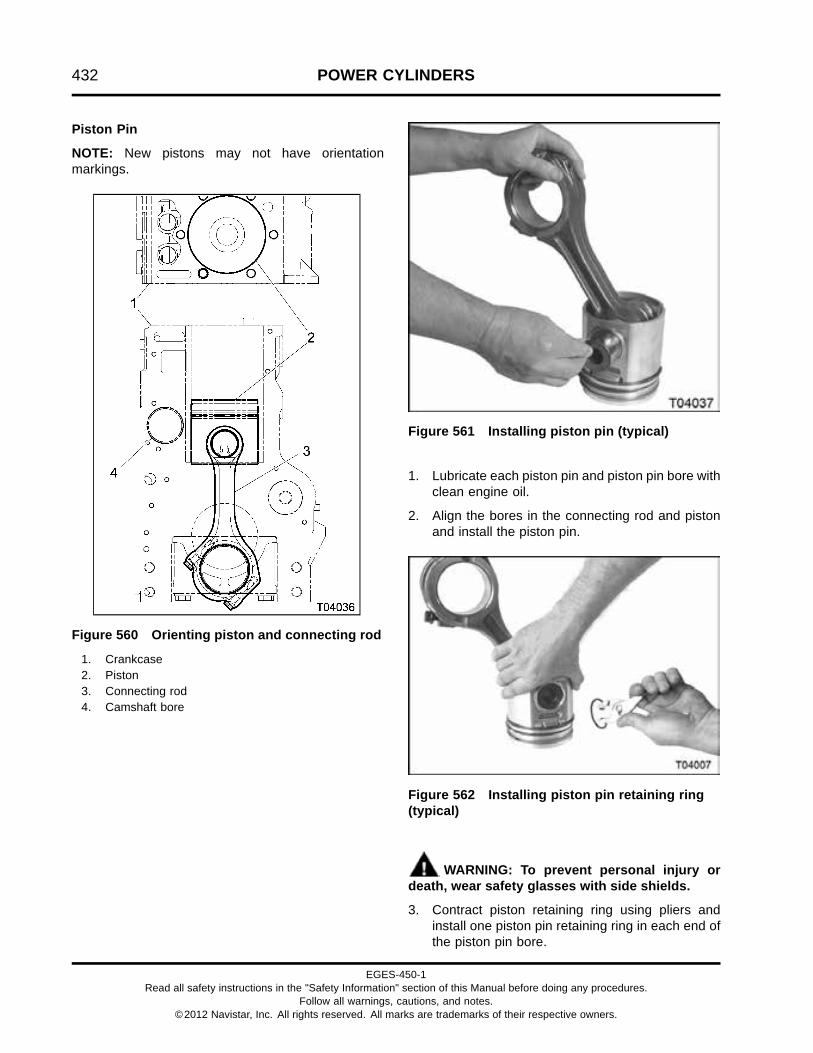
432 POWER CYLINDERS
Piston Pin
NOTE: New pistons may not have orientationmarkings.
Figure 560 Orienting piston and connecting rod
1. Crankcase2. Piston3. Connecting rod4. Camshaft bore
Figure 561 Installing piston pin (typical)
1. Lubricate each piston pin and piston pin bore withclean engine oil.
2. Align the bores in the connecting rod and pistonand install the piston pin.
Figure 562 Installing piston pin retaining ring(typical)
WARNING: To prevent personal injury ordeath, wear safety glasses with side shields.
3. Contract piston retaining ring using pliers andinstall one piston pin retaining ring in each end ofthe piston pin bore.
EGES-450-1Read all safety instructions in the "Safety Information" section of this Manual before doing any procedures.
Follow all warnings, cautions, and notes.©2012 Navistar, Inc. All rights reserved. All marks are trademarks of their respective owners.

POWER CYLINDERS 433
Piston and Connecting Rod Assembly
CAUTION: To prevent engine damage, do not allowthe connecting rod or connecting rod cap fracturedmating surfaces to contact any surface other thenits matched fractured surface. Contacting any othersurface will cause misalignment of the mating surface,resulting in connecting rod bearing and engine failure.
NOTE: Turn crankshaft so connecting rod journals 1and 6 are at Bottom Dead Center (BDC). Install pistonand connecting rod assemblies 1 and 6 first. Thenrepeat the procedure for piston and connecting rodassemblies 2 and 5. Finish with piston and connectingrod assemblies 3 and 4.
1. Install connecting rod bearings into connectingrods and connecting rod caps dry (without oil),being sure to fit bearing tabs into slots and placingthe ends of the bearings flush to rod and cap jointlines.
2. Lubricate bearing surface of bearing in connectingrod with clean engine oil.
3. Lubricate piston rings and inside diameter of thecylinder sleeve with clean engine oil. Staggerpiston ring gaps approximately 120° from eachother.
Figure 563 Piston Ring Compressor Tool
4. Install a Piston Ring Compressor Tool (page441) over the piston rings and compress the rings
down into the piston grooves, such that the ringswill fit into the cylinder sleeve. Be sure the ringsremain in their respective grooves during thisprocedure.
5. Re-confirm that the rod is properly assembled tothe piston: when installed, the piston will haveproper orientation and the connecting rod’s “openside” will face the CAM SIDE of the engine, whenviewed from above. If the piston has a CAMSIDE mark or a front-of-engine arrow, thesemarks should be properly aligned with engineorientation. Confirm that if a used piston isinstalled, it is going back into its previous cylindersleeve with the same orientation it had prior toremoval.
6. Carefully install the piston and connecting rodassembly into the cylinder sleeve.
Figure 564 Installing piston and connecting rodassembly
7. Push the piston and connecting rod assemblyinto the cylinder sleeve using a wooden or plastichandle. Carefully guide the connecting rod overthe crankshaft connecting rod journal. Do nottouch the crankshaft journal with the fracturedmating surface of the connecting rod.
EGES-450-1Read all safety instructions in the "Safety Information" section of this Manual before doing any procedures.
Follow all warnings, cautions, and notes.©2012 Navistar, Inc. All rights reserved. All marks are trademarks of their respective owners.

434 POWER CYLINDERS
Figure 565 Connecting rod and cap serialnumber locations
CAUTION: To prevent engine damage, eachconnecting rod cap serial number must be assembledon the same side as its connecting rod serial number(they must match). If the rod cap is reversed whenassembled on the connecting rod or a rod cap is notinstalled on its original matching connecting rod, thefractured mating surfaces will be ruined. The entireconnecting rod assembly must then be replaced.
Figure 566 Incorrect connecting rod caporientation
NOTE: If the connecting rod cap is reversed duringassembly, an obvious offset will be seen at the rodmating surfaces. If the connecting rod cap is installedin the reverse orientation, the connecting rod mustbe replaced. Also check the crankshaft journal fordamage.
EGES-450-1Read all safety instructions in the "Safety Information" section of this Manual before doing any procedures.
Follow all warnings, cautions, and notes.©2012 Navistar, Inc. All rights reserved. All marks are trademarks of their respective owners.

POWER CYLINDERS 435
NOTE: Each connecting rod cap mark must pointtoward the front of the engine.
8. Lubricate the connecting rod bearing insidediameter with clean engine oil.
Figure 567 Installing connecting rod cap
9. Carefully install connecting rod cap and two newrod bolts over the crankshaft journal and fingertighten rod bolts into connecting rod.
Figure 568 Connecting rod with M11 bolts (markpointing to front of engine)
10. Verify all connecting rods are properly installedwith mark pointing towards front of engine.
Torque-to-yield Procedure for Connecting Rods
NOTE: If performing bearing fit procedure, do nottorque-to-yield connecting rod cap bolts. Tightenconnecting rod cap bolts to 109 N·m (80 lbf·ft).
CAUTION: To prevent engine damage, do not usepower tools to remove or install connecting rod capbolts. Threads will be damaged if a bolt or nut isrotated too quickly.
1. Tighten two new M11 connecting rod bolts to 41N·m (30 lbf·ft).
Figure 569 M11 Connecting rod bolttorque-to-yield markings
1. Connecting rod bolt with permanent marker spot(before torque-to-yield)
2. Connecting rod bolt with permanent marker spot(after torque-to-yield)
3. Permanent marker spot on connecting rod cap
CAUTION: To prevent engine damage, usepermanent marker to identify internal enginecomponents and their orientation. Do not use paintor temporary markers.
2. Using a permanent marker, place a mark on eachconnecting rod bolt and put another mark on a 15mm 12 point socket (page 441) directly in line withthe mark on each rod bolt.
3. Put a mark on the connecting rod cap surface 90°clockwise from each rod bolt mark.
4. Install the socket on the rod bolt to be torqued andalign mark on socket with the mark on the rod bolt.
5. Torque-to-yield each M11 rod bolt by rotating boltexactly 90° clockwise (1/4 turn). The marks on thesocket, rod bolt, and connecting rod cap surfaceshould be aligned when finished.
EGES-450-1Read all safety instructions in the "Safety Information" section of this Manual before doing any procedures.
Follow all warnings, cautions, and notes.©2012 Navistar, Inc. All rights reserved. All marks are trademarks of their respective owners.

436 POWER CYLINDERS
Piston Cooling Tubes
Figure 570 Piston cooling tube assemblies
1. Piston cooling tube (unknurled) – MaxxForce® DTengines
2. Piston cooling tube (knurled) – MaxxForce® 9 and10 engines
CAUTION: To prevent engine damage, correct pistoncooling tube assemblies must be installed. Unknurledpiston cooling tube assemblies are required forMaxxForce® DT engines: A painted green stripedesignates Model Years 2007-2009. A paintedblue stripe designates Model Year 2010 and up.Knurled piston cooling tube assemblies, without apainted stripe, are required for MaxxForce® 9 and 10engines.
NOTE: The crankshaft may need to be rotated toinstall some piston cooling tubes.
NOTE: Piston cooling tubes are self aligning. Do notbend.
Figure 571 O-ring on underside of pistoncooling tube
1. Install a new O-ring onto piston cooling tubes.
Figure 572 Piston cooling tube
1. Piston cooling tube assembly (6)2. M6 x 12 piston cooling jet bolt (6)3. Crankcase mounting pad for piston cooling tube (6)
CAUTION: To prevent engine damage, piston coolingtubes use a special mounting bolt. Do not substitute.
2. Install six piston cooling tube assemblies andsix new M6 x 12 piston cooling jet bolts into thecrankcase mounting pads.
3. Tighten new M6 x 12 piston cooling jet bolts tospecial torque (page 440).
EGES-450-1Read all safety instructions in the "Safety Information" section of this Manual before doing any procedures.
Follow all warnings, cautions, and notes.©2012 Navistar, Inc. All rights reserved. All marks are trademarks of their respective owners.

POWER CYLINDERS 437
Engine Run-in Procedure
WARNING: To prevent personal injury ordeath, shift transmission to park or neutral, setparking brake, and block wheels before doingdiagnostic or service procedures.
If new pistons, piston rings, or cylinder sleeveshave been installed, use the following engine run-inprocedure:
1. Start engine and run at low idle with no load for 5minutes. Check for leaks in the cooling, oil, fuel,and air induction systems.
2. Check the turbocharger for all of the followingconditions:
• Unusual noise
• Oil leaks
• Air leaks
• Excessive exhaust smoke
• Excessive vibration
• Loose mounting
3. Turn engine off and correct any of these problemsto prevent engine or turbocharger damage.
4. Start engine and drive vehicle (unloaded) for25 minutes in city mode, then drive vehicle(unloaded) for an additional 15 minutes inhighway mode.
5. Return to idle and check for leaks.
EGES-450-1Read all safety instructions in the "Safety Information" section of this Manual before doing any procedures.
Follow all warnings, cautions, and notes.©2012 Navistar, Inc. All rights reserved. All marks are trademarks of their respective owners.

438 POWER CYLINDERS
Specifications
Connecting Rod Specifications
Bend (maximum) 0.051 mm (0.002 in)
Center-to-center distance between connecting rod bearing bore and piston pin bushing bore
MaxxForce® DT
MaxxForce® 9 and 10
239.600 to 239.702 mm (9.433 to 9.437 in)
219.4 to 219.5 mm (8.638 to 8.642 in)
Connecting rod bearing bore inside diameter 85.130 to 85.156 mm (3.3516 to 3.3526 in)
Connecting rod bearing inside diameter (installed) 80.05 to 80.10 mm (3.1518 to 3.1536 in)
Connecting rod bearing bore out-of-round (maximum) 0.02 mm (0.00078 in)
Connecting rod bearing bore taper (maximum) 0.02 mm (0.00078 in)
Connecting rod bearing running clearance 0.030 to 0.107 mm (0.0012 to 0.0042 in)
Connecting rod to crankshaft side clearance 0.190 to 0.419 mm (0.0075 to 0.0165 in)
Twist (maximum) 0.051 mm (0.002 in)
Piston pin bushing inside diameter
MaxxForce® DT
MaxxForce® 9 and 10
48.039 to 48.047 mm (1.8913 to 1.892 in)
46.393 to 46.401 mm (1.8265 to 1.8268 in)
Piston Specifications – MaxxForce® DT
Piston One-piece aluminum
Top ring - keystone cross sectionPiston rings
Intermediate - rectangular cross section
Running clearance between piston and cylinder sleeve 0.088 to 0.132 mm (0.00335 to 0.00524 in)
Skirt diameter 116.467 to 116.485 mm (4.5853 to 4.5860 in)
Top compression ring groove width, measure over 2.885 mm(0.1135 in) gauge pins
117.325 to 117.545 mm (4.6191 to 4.6278 in)
Intermediate compression ring side clearance 0.05 to 0.10 mm (0.002 to 0.0039 in)
Oil control ring side clearance 0.03 to 0.08 mm (0.0012 to 0.00315 in)
Piston protrusion above crankcase top deck 0.622 to 0.813 mm (0.025 to 0.032 in)
Piston cooling tube diameter (spray hole) 2.18 mm (0.086 in)
EGES-450-1Read all safety instructions in the "Safety Information" section of this Manual before doing any procedures.
Follow all warnings, cautions, and notes.©2012 Navistar, Inc. All rights reserved. All marks are trademarks of their respective owners.

POWER CYLINDERS 439
Piston Specifications – MaxxForce® 9 and 10
Piston One-piece steel
Top ring - keystone cross sectionPiston rings
Intermediate - rectangular cross section
Running clearance between piston and cylinder sleeve 0.085 to 0.133 mm (0.00335 to 0.00524 in)
Skirt diameter 116.498 to 116.528 mm (4.5865 to 4.5877 in)
Top compression ring groove width, measure over 2.70mm (0.1063 in) gauge pins
116.104 to 116.304 mm (4.5710 to 4.5866 in)
Intermediate compression ring side clearance 0.07 to 0.12 mm (0.0028 to 0.0047 in)
Oil control ring side clearance 0.03 to 0.08 mm (0.0012 to 0.00315 in)
Piston protrusion above crankcase top deck 0.622 to 0.813 mm (0.025 to 0.032 in)
Piston Ring Specifications (in 116.573 mm diameter gage ring)
Top compression ring end gap 0.35 to 0.50 mm (0.014 to 0.0197 in)
Intermediate compression ring end gap 1.20 to 1.45 mm (0.0472 to 0.0571 in)
Oil control ring end gap 0.35 to 0.65 mm (0.014 to 0.0256 in)
Piston Pin Specifications
Clearance in piston
MaxxForce® DT
MaxxForce® 9 and 10
0.006 to 0.016 mm (0.00024 to 0.00063 in)
0.083 to 0.103 mm (0.00327 to 0.00406 in)
Length
MaxxForce® DT
MaxxForce® 9 and 10
94.3 to 94.6 mm (3.7126 to 3.7244 in)
77.88 to 78.13 mm (3.066 to 3.076 in)
Diameter
MaxxForce® DT
MaxxForce® 9 and 10
46.352 to 46.357 mm (1.8249 to 1.8251 in)
47.997 to 48.002 mm (1.8896 to 1.8898 in)
EGES-450-1Read all safety instructions in the "Safety Information" section of this Manual before doing any procedures.
Follow all warnings, cautions, and notes.©2012 Navistar, Inc. All rights reserved. All marks are trademarks of their respective owners.

440 POWER CYLINDERS
Cylinder Sleeve Specifications
Counterbore depth allowable variation between fourpoints (maximum)
0.03 mm (0.001 in)
Counterbore depth before adding shims (maximum) 10.49 mm (0.413 in)
Counterbore depth (including shims - if any) 8.84 to 8.89 mm (0.348 to 0.350 in)
Cylinder sleeve protrusion 0.05 to 0.13 mm (0.002 to 0.005 in)
Cylinder sleeve protrusion difference between all sixsleeves (maximum)
0.03 mm (0.001 in)
Cylinder sleeve taper travel (maximum) 0.10 mm (0.004 in)
Flange thickness 8.94 to 8.96 mm (0.352 to 0.353 in)
Inside diameter 116.57 to 116.60 mm (4.5895 to 4.5905 in)
Special Torque
Connecting rod bolts See Torque-to-yield Procedure for Connecting Rods withM11 bolts (page 435).
Piston cooling jet bolts, M6 x 12 13 N·m (114 lbf·in)
EGES-450-1Read all safety instructions in the "Safety Information" section of this Manual before doing any procedures.
Follow all warnings, cautions, and notes.©2012 Navistar, Inc. All rights reserved. All marks are trademarks of their respective owners.
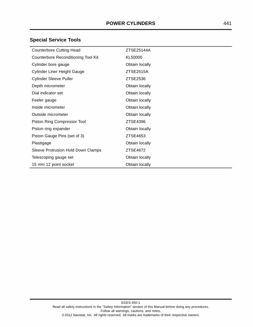
POWER CYLINDERS 441
Special Service Tools
Counterbore Cutting Head ZTSE25144A
Counterbore Reconditioning Tool Kit KL50000
Cylinder bore gauge Obtain locally
Cylinder Liner Height Gauge ZTSE2515A
Cylinder Sleeve Puller ZTSE2536
Depth micrometer Obtain locally
Dial indicator set Obtain locally
Feeler gauge Obtain locally
Inside micrometer Obtain locally
Outside micrometer Obtain locally
Piston Ring Compressor Tool ZTSE4396
Piston ring expander Obtain locally
Piston Gauge Pins (set of 3) ZTSE4653
Plastigage Obtain locally
Sleeve Protrusion Hold Down Clamps ZTSE4672
Telescoping gauge set Obtain locally
15 mm 12 point socket Obtain locally
EGES-450-1Read all safety instructions in the "Safety Information" section of this Manual before doing any procedures.
Follow all warnings, cautions, and notes.©2012 Navistar, Inc. All rights reserved. All marks are trademarks of their respective owners.

442 POWER CYLINDERS
EGES-450-1Read all safety instructions in the "Safety Information" section of this Manual before doing any procedures.
Follow all warnings, cautions, and notes.©2012 Navistar, Inc. All rights reserved. All marks are trademarks of their respective owners.

CRANKCASE, CRANKSHAFT, AND CAMSHAFT 443
Table of Contents
Exploded Views and Description. . . . . . . . . . . . . . . . . . . . . . . . . . . . . . . . . . . . . . . . . . . . . . . . . . . . . . . . . . . . . . . . . . . . . . . . . . . . . . . . . . . .445Crankcase Breather Assembly with Turbine. . . . . . . . . . . . . . . . . . . . . . . . . . . . . . . . . . . . . . . . . . . . . . . . . . . . . . . . . . . .445Crankcase, Crankshaft, and Camshaft. . . . . . . . . . . . . . . . . . . . . . . . . . . . . . . . . . . . . . . . . . . . . . . . . . . . . . . . . . . . . . . . . . .446
Removal. . . . . . . . . . . . . . . . . . . . . . . . . . . . . . . . . . . . . . . . . . . . . . . . . . . . . . . . . . . . . . . . . . . . . . . . . . . . . . . . . . . . . . . . . . . . . . . . . . . . . . . . . . . . . . . . .448Crankcase Ventilation System.. . . . . . . . . . . . . . . . . . . . . . . . . . . . . . . . . . . . . . . . . . . . . . . . . . . . . . . . . . . . . . . . . . . . . . . . . . . .448Oil Level Gauge Assembly. . . . . . . . . . . . . . . . . . . . . . . . . . . . . . . . . . . . . . . . . . . . . . . . . . . . . . . . . . . . . . . . . . . . . . . . . . . . . . . . . .450Coolant Heater Assembly (Optional). . . . . . . . . . . . . . . . . . . . . . . . . . . . . . . . . . . . . . . . . . . . . . . . . . . . . . . . . . . . . . . . . . . . . .450Crankcase Ladder Assembly. . . . . . . . . . . . . . . . . . . . . . . . . . . . . . . . . . . . . . . . . . . . . . . . . . . . . . . . . . . . . . . . . . . . . . . . . . . . . . .450Camshaft Gear. . . . . . . . . . . . . . . . . . . . . . . . . . . . . . . . . . . . . . . . . . . . . . . . . . . . . . . . . . . . . . . . . . . . . . . . . . . . . . . . . . . . . . . . . . . . . . . .451Camshaft Assembly. . . . . . . . . . . . . . . . . . . . . . . . . . . . . . . . . . . . . . . . . . . . . . . . . . . . . . . . . . . . . . . . . . . . . . . . . . . . . . . . . . . . . . . . . .452Camshaft Bearings.. . . . . . . . . . . . . . . . . . . . . . . . . . . . . . . . . . . . . . . . . . . . . . . . . . . . . . . . . . . . . . . . . . . . . . . . . . . . . . . . . . . . . . . . . .453Main Bearing Caps, Crankshaft, and Main Bearings. . . . . . . . . . . . . . . . . . . . . . . . . . . . . . . . . . . . . . . . . . . . . . . . . . .455Oil Pump Spline Drive and Crankshaft Gear. . . . . . . . . . . . . . . . . . . . . . . . . . . . . . . . . . . . . . . . . . . . . . . . . . . . . . . . . . . .456
Cleaning, Inspection, and Measurement. . . . . . . . . . . . . . . . . . . . . . . . . . . . . . . . . . . . . . . . . . . . . . . . . . . . . . . . . . . . . . . . . . . . . . . . . . .457Camshaft Assembly. . . . . . . . . . . . . . . . . . . . . . . . . . . . . . . . . . . . . . . . . . . . . . . . . . . . . . . . . . . . . . . . . . . . . . . . . . . . . . . . . . . . . . . . . .457Crankcase Breather Assembly. . . . . . . . . . . . . . . . . . . . . . . . . . . . . . . . . . . . . . . . . . . . . . . . . . . . . . . . . . . . . . . . . . . . . . . . . . . . .457Crankcase, Cup Plugs, and Piston Cooling Tubes.. . . . . . . . . . . . . . . . . . . . . . . . . . . . . . . . . . . . . . . . . . . . . . . . . . . .457Crankshaft and Main Bearings.. . . . . . . . . . . . . . . . . . . . . . . . . . . . . . . . . . . . . . . . . . . . . . . . . . . . . . . . . . . . . . . . . . . . . . . . . . . .459Camshaft End Play Measurement. . . . . . . . . . . . . . . . . . . . . . . . . . . . . . . . . . . . . . . . . . . . . . . . . . . . . . . . . . . . . . . . . . . . . . . . .460Camshaft Lobes and Journals Measurement. . . . . . . . . . . . . . . . . . . . . . . . . . . . . . . . . . . . . . . . . . . . . . . . . . . . . . . . . . .460Crankshaft End Play Measurement. . . . . . . . . . . . . . . . . . . . . . . . . . . . . . . . . . . . . . . . . . . . . . . . . . . . . . . . . . . . . . . . . . . . . . .461
Installation. . . . . . . . . . . . . . . . . . . . . . . . . . . . . . . . . . . . . . . . . . . . . . . . . . . . . . . . . . . . . . . . . . . . . . . . . . . . . . . . . . . . . . . . . . . . . . . . . . . . . . . . . . . . . .462Camshaft Bearings.. . . . . . . . . . . . . . . . . . . . . . . . . . . . . . . . . . . . . . . . . . . . . . . . . . . . . . . . . . . . . . . . . . . . . . . . . . . . . . . . . . . . . . . . . .462Camshaft Assembly. . . . . . . . . . . . . . . . . . . . . . . . . . . . . . . . . . . . . . . . . . . . . . . . . . . . . . . . . . . . . . . . . . . . . . . . . . . . . . . . . . . . . . . . . .465Camshaft Gear. . . . . . . . . . . . . . . . . . . . . . . . . . . . . . . . . . . . . . . . . . . . . . . . . . . . . . . . . . . . . . . . . . . . . . . . . . . . . . . . . . . . . . . . . . . . . . . .465Crankshaft Gear and Oil Pump Spline Drive. . . . . . . . . . . . . . . . . . . . . . . . . . . . . . . . . . . . . . . . . . . . . . . . . . . . . . . . . . . .466Upper Main Bearings and Crankshaft Assembly. . . . . . . . . . . . . . . . . . . . . . . . . . . . . . . . . . . . . . . . . . . . . . . . . . . . . . .467Main Bearing Fit Procedure. . . . . . . . . . . . . . . . . . . . . . . . . . . . . . . . . . . . . . . . . . . . . . . . . . . . . . . . . . . . . . . . . . . . . . . . . . . . . . . .469Main Bearings and Caps. . . . . . . . . . . . . . . . . . . . . . . . . . . . . . . . . . . . . . . . . . . . . . . . . . . . . . . . . . . . . . . . . . . . . . . . . . . . . . . . . . . .471Torque Procedure for Torque-to-yield Main Bearing Cap Bolts. . . . . . . . . . . . . . . . . . . . . . . . . . . . . . . . . . . . . .472Crankcase Ladder Assembly. . . . . . . . . . . . . . . . . . . . . . . . . . . . . . . . . . . . . . . . . . . . . . . . . . . . . . . . . . . . . . . . . . . . . . . . . . . . . . .473Coolant Heater Assembly (Optional). . . . . . . . . . . . . . . . . . . . . . . . . . . . . . . . . . . . . . . . . . . . . . . . . . . . . . . . . . . . . . . . . . . . . .474Oil Level Gauge Assembly. . . . . . . . . . . . . . . . . . . . . . . . . . . . . . . . . . . . . . . . . . . . . . . . . . . . . . . . . . . . . . . . . . . . . . . . . . . . . . . . . .475Crankcase Ventilation System.. . . . . . . . . . . . . . . . . . . . . . . . . . . . . . . . . . . . . . . . . . . . . . . . . . . . . . . . . . . . . . . . . . . . . . . . . . . .476
Specifications. . . . . . . . . . . . . . . . . . . . . . . . . . . . . . . . . . . . . . . . . . . . . . . . . . . . . . . . . . . . . . . . . . . . . . . . . . . . . . . . . . . . . . . . . . . . . . . . . . . . . . . . . .478
Special Torque.. . . . . . . . . . . . . . . . . . . . . . . . . . . . . . . . . . . . . . . . . . . . . . . . . . . . . . . . . . . . . . . . . . . . . . . . . . . . . . . . . . . . . . . . . . . . . . . . . . . . . . . . .481
Special Service Tools. . . . . . . . . . . . . . . . . . . . . . . . . . . . . . . . . . . . . . . . . . . . . . . . . . . . . . . . . . . . . . . . . . . . . . . . . . . . . . . . . . . . . . . . . . . . . . . . .482
EGES-450-1Read all safety instructions in the "Safety Information" section of this Manual before doing any procedures.
Follow all warnings, cautions, and notes.©2012 Navistar, Inc. All rights reserved. All marks are trademarks of their respective owners.

444 CRANKCASE, CRANKSHAFT, AND CAMSHAFT
EGES-450-1Read all safety instructions in the "Safety Information" section of this Manual before doing any procedures.
Follow all warnings, cautions, and notes.©2012 Navistar, Inc. All rights reserved. All marks are trademarks of their respective owners.

CRANKCASE, CRANKSHAFT, AND CAMSHAFT 445
Exploded Views and DescriptionCrankcase Breather Assembly with Turbine
Figure 573 Crankcase breather assembly with turbine
1. M5 x 16 bolt (2)2. Inlet elbow3. Breather fitting seal (2)4. Housing assembly (breather)5. M6 x 30 bolt (3)
6. Breather turbine seal7. M8 x 30 bolt (used with coolant
return tube supports) (3)8. Housing assembly (turbine)9. M8 x 25 bolt (3)
10. Breather to crankcase seal11. M5 x 10 bolt (2)12. Breather flange13. Breather elbow
The crankcase breather assembly separates oilfrom crankcase gases. A turbine in the breatherhousing assembly is driven by engine oil pressure
that separates the oil mist from crankcase gases. Theclosed breather system returns crankcase gases tothe engine intake air and oil to the oil pan.
EGES-450-1Read all safety instructions in the "Safety Information" section of this Manual before doing any procedures.
Follow all warnings, cautions, and notes.©2012 Navistar, Inc. All rights reserved. All marks are trademarks of their respective owners.

446 CRANKCASE, CRANKSHAFT, AND CAMSHAFT
Crankcase, Crankshaft, and Camshaft
Figure 574 Crankcase, Crankshaft, and Camshaft
EGES-450-1Read all safety instructions in the "Safety Information" section of this Manual before doing any procedures.
Follow all warnings, cautions, and notes.©2012 Navistar, Inc. All rights reserved. All marks are trademarks of their respective owners.

CRANKCASE, CRANKSHAFT, AND CAMSHAFT 447
1. Camshaft gear assembly2. M8 x 20 bolt (2)3. Camshaft thrust plate4. Woodruff key, ¼ x ¾5. Roller tappet assembly (12)6. Roller tappet guide (12)7. Camshaft8. Front #1 bearing (camshaft)9. Intermediate #2 and #3 bearing
(camshaft) (2)10. Rear #4 bearing (camshaft)11. Valve cover
12. Camshaft seal, ring (rear)13. Crankcase assembly14. Oil level gauge assembly15. Thrust main bearing (#7 upper)16. M12 Tee assembly17. Crankshaft18. Crankcase ladder19. M10 x 25 bolt (10)20. M12 x 35 bolt (14)21. M15 x 162 bearing cap bolt (14)22. Spacer (14)23. Main bearing cap (7)
24. Lower main bearing (7)25. Oil pump spline drive26. Crankshaft gear27. Slotted spring pin, 5/32 x 5/1628. Front & intermediate upper main
bearing (6)29. M6 x 12 piston cooling tube bolt
(6)30. Piston cooling tube with O-ring
assembly (6)31. Coolant heater assembly
(optional)
The one piece cast grey iron crankcase hasremovable cylinder sleeves and seven main bearingcaps with 2 bolts per main cap.
The forged steel crankshaft has one journal for eachconnecting rod and thrust is taken by number 7 uppermain bearing.
The single roller tappet camshaft is gear driven by theupper idler gear.
EGES-450-1Read all safety instructions in the "Safety Information" section of this Manual before doing any procedures.
Follow all warnings, cautions, and notes.©2012 Navistar, Inc. All rights reserved. All marks are trademarks of their respective owners.

448 CRANKCASE, CRANKSHAFT, AND CAMSHAFT
Removal
GOVERNMENT REGULATION: Enginefluids (oil, fuel, and coolant) may be a hazardto human health and the environment.Handle all fluids and other contaminatedmaterials (e.g. filters, rags) in accordancewith applicable regulations. Recycleor dispose of engine fluids, filters, andother contaminated materials according toapplicable regulations.
WARNING: To prevent personal injury ordeath, read all safety instructions in the “SafetyInformation” section of this manual.
WARNING: To prevent personal injury ordeath, shift transmission to park or neutral, setparking brake, and block wheels before doingdiagnostic or service procedures.
WARNING: To prevent personal injury ordeath, allow engine to cool before working withcomponents.
WARNING: To prevent personal injury ordeath, disconnect ground (-) cable from batterybefore doing service or diagnostic procedures.
WARNING: To prevent personal injury ordeath, wear safety glasses with side shields.Limit compressed air pressure to 207 kPa (30 psi).
WARNING: To prevent personal injury ordeath, do not let engine fluids stay on your skin.Clean skin and nails using hand cleaner and washwith soap and water. Wash or discard clothingand rags contaminated with engine fluids.
Crankcase Ventilation System
NOTE: If not previously done, drain coolant from thecoolant drain plug located in the oil cooler module,before removing the crankcase breather from theengine.
Figure 575 Crankcase breather assembly andtubes
1. Port elbow2. Crankcase breather outlet tube3. Crankcase breather inlet tube4. Crankcase breather inlet tube hose clamp (2)5. Crankcase breather assembly with turbine6. Coolant return tube assembly (two tubes and
interconnecting hose)7. High and low-pressure turbo drain tube hose clamp
(4)8. High-pressure turbo drain hose9. Low-pressure turbo drain hose10. Oil cooler module11. Breather elbow12. Crankcase breather outlet tube hose clamp13. High and low-pressure turbo drain tube clamp14. M8 x 25 bolt
EGES-450-1Read all safety instructions in the "Safety Information" section of this Manual before doing any procedures.
Follow all warnings, cautions, and notes.©2012 Navistar, Inc. All rights reserved. All marks are trademarks of their respective owners.

CRANKCASE, CRANKSHAFT, AND CAMSHAFT 449
NOTE: Two different size bolts secure the crankcasebreather assembly to the crankcase. There are threeM8 x 30 bolts securing the two bottom and middle rightside of the crankcase breather assembly as well assecuring the coolant return tube supports. The otherthree bolts are M8 x 25, secure the crankcase breatherassembly to the crankcase. The correct bolts must beplaced in the correct locations to correctly secure thecrankcase breather assembly to the crankcase.
1. Place a drain pan under the coolant return tubeassembly.
2. Loosen and remove, do not discard three M8x 30 bolts which secure the coolant return tubesupports to the crankcase breather assembly andcoolant supply housing.
3. Pull coolant tube out of the coolant supply housingand the oil cooler module.
4. Discard coolant return tube assembly O-rings(one on each end of assembly). Place coolantreturn tube assembly on a clean workbench.
5. Dispose of coolant per applicable regulations.
6. Loosen hose clamp securing breather outlet tubeto breather elbow. Disconnect breather outlettube from breather elbow.
7. Loosen hose clamp securing breather outlet tubeto port elbow. Disconnect breather outlet tubefrom port elbow and place breather outlet tube ona clean workbench.
8. Loosen hose clamps connecting high andlow-pressure turbo drain tubes to high andlow-pressure turbo hoses.
9. Remove M8 x 25 bolt securing the high andlow-pressure turbo drain tube clamp to the EGR.Do not discard bolt.
10. Remove, do not discard, high and low-pressureturbo drain tube clamp.
11. Pull high and low-pressure turbo drain tubes off ofturbochargers and crankcase breather assembly.
12. Loosen hose clamps securing breather inlet tubeto inlet elbow on crankcase breather assembly.
13. Pull breather inlet tube off of inlet elbow.
14. Loosen and remove three M8 x 25 bolts securingcrankcase breather assembly to crankcase.
15. Remove crankcase breather assembly fromcrankcase.
Figure 576 Crankcase breather housingassembly (turbine) and seal
1. Housing assembly (turbine)2. Breather to crankcase seal
16. Remove and discard breather to crankcase sealfrom housing assembly (turbine).
EGES-450-1Read all safety instructions in the "Safety Information" section of this Manual before doing any procedures.
Follow all warnings, cautions, and notes.©2012 Navistar, Inc. All rights reserved. All marks are trademarks of their respective owners.

450 CRANKCASE, CRANKSHAFT, AND CAMSHAFT
Oil Level Gauge Assembly
Figure 577 Oil level gauge assembly
1. Cushioned clamp2. Oil filler tube support3. Oil level gauge tube4. Tube clamp5. Oil filler tube6. M6 x 25 bolt and M6 nut
1. Remove M6 x 25 bolt and M6 nut securing the oilfiller tube to the oil filler tube support.
2. Loosen tube clamp and remove the oil filler tubeassembly from the oil level gauge tube.
3. If required, remove the oil filler tube support.Remove two M8 nuts and one M6 x 16 boltholding the oil filler tube support to the fuel filterheader.
4. If required, remove the oil level gauge tube bydriving the tube up and out of the crankcase usinga brass punch and hammer.
Coolant Heater Assembly (Optional)
Figure 578 Coolant heater (intake side ofcrankcase)
1. Coolant heater mounting flange2. M8 x 20 bolt
1. If not previously done, drain engine coolant to alevel below the coolant heater. Dispose of enginecoolant according to applicable regulations.
2. Remove M8 x 20 bolt.
3. Pull out and remove coolant heater assembly fromcrankcase.
4. Discard O-ring.
Crankcase Ladder Assembly
1. Drain engine oil. See Drain Oil (page 62).
2. Remove oil pan (page 269) and oil suction tubeassembly (page 270).
3. Rotate engine on stand to bring the crankcase tothe vertical position so components do not fall intothe crankcase.
EGES-450-1Read all safety instructions in the "Safety Information" section of this Manual before doing any procedures.
Follow all warnings, cautions, and notes.©2012 Navistar, Inc. All rights reserved. All marks are trademarks of their respective owners.

CRANKCASE, CRANKSHAFT, AND CAMSHAFT 451
Figure 579 Crankcase ladder assembly (typical)
1. M12 x 35 bolt (14)2. M10 x 25 bolt hole (10)3. Crankcase ladder4. Spacer (14)5. Main bearing cap (7)
NOTE: Plastic washers are used as an assembly aidto hold each bolt and spacer to the crankcase ladder.Plastic washers are not required.
4. Remove ten M10 x 25 bolts securing thecrankcase ladder to the crankcase.
5. Loosen fourteen M12 x 35 bolts securing thecrankcase ladder to the main bearing caps andremove crankcase ladder assembly from theengine.
6. Remove 14 loose spacers that were under thecrankcase ladder at the M12 x 35 bolt locations.
7. Carefully inspect crankcase for broken debrisfrom plastic washers or washers that may havefallen into the crankcase. Remove and discardall plastic washers and any debris from plastic
washers found in the crankcase or on the ladderassembly.
Camshaft Gear
Figure 580 Camshaft gear and Cam Gear Puller
NOTE: Before removing the camshaft, measurecamshaft end play (page 460). For easier camshaftgear removal, remove the camshaft gear beforeremoving camshaft, using the following procedure.To remove the camshaft and gear as an assembly,skip this procedure and go to Camshaft Assembly.
1. Bar engine until the number 1 cylinder is at TopDead Center (TDC)
2. Install two claws of the Cam Gear Puller (page482) into two holes of the camshaft gear.
3. Center the gear puller threaded shaft on thecenter of the camshaft and tighten shaft whilefirmly attaching puller claws on the camshaft gear.
NOTE: Keep the Cam Gear Puller center shaft in linewith the camshaft center line while removing the camgear.
4. Remove the camshaft gear by rotating the gearpuller center shaft in a continuous motion using a
EGES-450-1Read all safety instructions in the "Safety Information" section of this Manual before doing any procedures.
Follow all warnings, cautions, and notes.©2012 Navistar, Inc. All rights reserved. All marks are trademarks of their respective owners.

452 CRANKCASE, CRANKSHAFT, AND CAMSHAFT
breaker bar, while holding the camshaft gear andCam Gear Puller from rotating.
Camshaft Assembly
Figure 581 Camshaft thrust plate bolts (typical)
1. M8 x 20 bolt (2)2. Camshaft
NOTE: Roller tappets must be removed beforeremoving camshaft. See Roller Tappets and Guides(page 340).
1. Remove two M8 x 20 camshaft thrust plate bolts.
Figure 582 Camshaft assembly removal (typical)
2. Rotate engine on stand so camshaft can be pulledstraight up.
3. Carefully pull camshaft assembly up and out ofcrankcase.
EGES-450-1Read all safety instructions in the "Safety Information" section of this Manual before doing any procedures.
Follow all warnings, cautions, and notes.©2012 Navistar, Inc. All rights reserved. All marks are trademarks of their respective owners.

CRANKCASE, CRANKSHAFT, AND CAMSHAFT 453
Camshaft Bearings
Figure 583 Camshaft Bearing Puller (installer)
1. Puller screw2. Pulling nut3. Thrust bearing4. Pulling plate5. Pulling spacer
6. Extension tube7. Puller screw extension8. Camshaft bearing (not part of
tool)9. Expanding collet
10. Backup nut
NOTE: Although the inside diameter of each camshaftbearing is the same, the outside diameters andwidths are different depending on bearing location.See crankcase and camshaft bearing Specifications(page 478).
Use Camshaft Bearing Puller (page 482) to removecamshaft bearings. Remove the front and rearcamshaft bearings first. Remove the camshaft sealring and rear camshaft bearing from the rear of thecrankcase.
1. Assemble the correct expanding collet andbackup nut on the puller screw extension. Seecamshaft bearing Specifications (page 478).
EGES-450-1Read all safety instructions in the "Safety Information" section of this Manual before doing any procedures.
Follow all warnings, cautions, and notes.©2012 Navistar, Inc. All rights reserved. All marks are trademarks of their respective owners.

454 CRANKCASE, CRANKSHAFT, AND CAMSHAFT
Figure 584 Camshaft bearing removal pull direction
1. Front of engine2. Crankcase assembly
3. Front and rear camshaftbearings
4. Intermediate camshaft bearings5. Camshaft seal ring
2. Remove the camshaft seal ring from the back ofthe crankcase.
3. With the expanding collet collapsed, install thecollet assembly in the camshaft bearing andtighten backup nut until the collet fits the camshaftbearing.
4. Assemble the Camshaft Bearing Puller and installextension tube on the puller screw extension.
NOTE: Make sure pulling spacer is squarely mountedon the crankcase before tightening pulling nut.
5. Hold the end of the puller screw with a wrench andtighten the pulling nut against the thrust bearingand pulling plate until the camshaft bearing isremoved.
6. Remove the front and rear camshaft bearings andthen remove the two intermediate bearings usingthe pull direction indicated in (Figure 584).
EGES-450-1Read all safety instructions in the "Safety Information" section of this Manual before doing any procedures.
Follow all warnings, cautions, and notes.©2012 Navistar, Inc. All rights reserved. All marks are trademarks of their respective owners.

CRANKCASE, CRANKSHAFT, AND CAMSHAFT 455
Main Bearing Caps, Crankshaft, and MainBearings
1. Disconnect the connecting rod assemblies. SeePiston and Connecting Rod Assembly (page 409).
Figure 585 Main bearing cap and crankcasestamps (typical)
1. Crankcase stamp for #7 main bearing2. Main bearing cap stamp on #7 main bearing cap3. M15 x 162 main bearing cap bolt (14)
NOTE: Crankcase and main bearing caps may needto be cleaned to see stamped numbers.
2. Verify main bearing caps and crankcase havecorresponding numbers stamped in each.
3. Loosen fourteen M15 x 162 main bearing capbolts.
Figure 586 Main bearing cap removal
4. Lift up both bolts of each main bearing cap soabout half the threads are exposed.
5. Rock each main bearing cap free from thecrankcase using both main bearing cap bolts.
6. Remove each main bearing cap and discard mainbearing cap bolts.
NOTE: Main bearing cap bolts are not reusable, dueto permanent deformation caused when bolts aretightened to the yield point (torque-to-yield).
Figure 587 Crankshaft assembly removal
CAUTION: To prevent engine damage, do not drop orbend the crankshaft.
WARNING: To prevent personal injury ordeath, use a correct size lifting sling and hoistwith a safety latch on hook.
7. Place an appropriate sling around the middle ofthe crankshaft and attach the sling to a hoist orcrane.
8. Carefully lift the crankshaft out of the crankcase.
EGES-450-1Read all safety instructions in the "Safety Information" section of this Manual before doing any procedures.
Follow all warnings, cautions, and notes.©2012 Navistar, Inc. All rights reserved. All marks are trademarks of their respective owners.

456 CRANKCASE, CRANKSHAFT, AND CAMSHAFT
Figure 588 Thrust main bearing removal
9. Push thrust main bearing and six other uppermain bearings out of the crankcase main bearingsaddles by hand. Mark each upper main bearingwith its bearing number and orientation. Set asideeach upper main bearing with its correspondinglower main bearing for later inspection andmeasurements.
Oil Pump Spline Drive and Crankshaft Gear
Figure 589 Oil pump spline drive removal
CAUTION: To prevent engine damage, strike chiselcarefully to prevent damage to the crankshaft duringoil pump spline drive and crankshaft gear removal.
1. Inspect oil pump drive spline for excessive wear.If worn, remove oil pump drive spline. Place chiselbetween teeth of oil pump drive spline. Strikechisel with hammer to break spline off crankshaft.
2. Remove oil pump drive spline from the crankshaft.
3. If worn or chipped, remove crankshaft gear. Placechisel between teeth of crankshaft gear. Strikechisel with hammer to break gear off crankshaft.
4. Remove crankshaft gear from the crankshaft.
EGES-450-1Read all safety instructions in the "Safety Information" section of this Manual before doing any procedures.
Follow all warnings, cautions, and notes.©2012 Navistar, Inc. All rights reserved. All marks are trademarks of their respective owners.

CRANKCASE, CRANKSHAFT, AND CAMSHAFT 457
Cleaning, Inspection, andMeasurementCamshaft Assembly
1. Use a soft bristle brush and a suitable solvent toclean the camshaft assembly and camshaft gear.
2. Inspect the camshaft gear for worn and damagedteeth. Replace gear if necessary.
3. Inspect camshaft for scuffed, scored, and crackedlobes. Replace camshaft if necessary.
4. Inspect the camshaft thrust plate for wear, cracks,and distortion. Replace thrust plate if necessary.
5. Measure camshaft thrust plate thickness using anoutside micrometer. Replace thrust plate if notwithin Specifications (page 478).
Crankcase Breather Assembly
1. Clean all tubing, hoses, and crankcase breatherassembly.
WARNING: To prevent personal injury ordeath, wear safety glasses. Limit compressed airpressure to 207 kPa (30 psi).
2. Dry parts with filtered compressed air.
3. Inspect tubing, hoses, and crankcase breatherassembly for leaks or cracks. Replace crackedor leaking parts.
Crankcase, Cup Plugs, and Piston Cooling Tubes
NOTE: The best way to clean the crankcase duringan engine overhaul is in a chemical bath or “hot tank”.If hot tank cleaning is not available, use the followingcleaning procedure.
1. Remove deposits and gasket material fromgasket surfaces using a rotary wire brush orsanding block with mineral spirits.
Figure 590 Crankcase cup (freeze) plug removal
2. Remove the main oil gallery cup plug, located inthe rear of the crankcase. Carefully knock out cupplugs with a hammer and chisel.
3. Clean oil galleries in the crankcase using a StiffNylon Brush (page 482) with soap and water.
EGES-450-1Read all safety instructions in the "Safety Information" section of this Manual before doing any procedures.
Follow all warnings, cautions, and notes.©2012 Navistar, Inc. All rights reserved. All marks are trademarks of their respective owners.
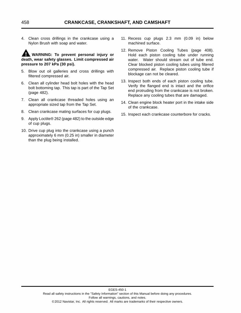
458 CRANKCASE, CRANKSHAFT, AND CAMSHAFT
4. Clean cross drillings in the crankcase using aNylon Brush with soap and water.
WARNING: To prevent personal injury ordeath, wear safety glasses. Limit compressed airpressure to 207 kPa (30 psi).
5. Blow out oil galleries and cross drillings withfiltered compressed air.
6. Clean all cylinder head bolt holes with the headbolt bottoming tap. This tap is part of the Tap Set(page 482).
7. Clean all crankcase threaded holes using anappropriate sized tap from the Tap Set.
8. Clean crankcase mating surfaces for cup plugs.
9. Apply Loctite® 262 (page 482) to the outside edgeof cup plugs.
10. Drive cup plug into the crankcase using a punchapproximately 6 mm (0.25 in) smaller in diameterthan the plug being installed.
11. Recess cup plugs 2.3 mm (0.09 in) belowmachined surface.
12. Remove Piston Cooling Tubes (page 408).Hold each piston cooling tube under runningwater. Water should stream out of tube end.Clear blocked piston cooling tubes using filteredcompressed air. Replace piston cooling tube ifblockage can not be cleared.
13. Inspect both ends of each piston cooling tube.Verify the flanged end is intact and the orificeend protruding from the crankcase is not broken.Replace any cooling tubes that are damaged.
14. Clean engine block heater port in the intake sideof the crankcase.
15. Inspect each crankcase counterbore for cracks.
EGES-450-1Read all safety instructions in the "Safety Information" section of this Manual before doing any procedures.
Follow all warnings, cautions, and notes.©2012 Navistar, Inc. All rights reserved. All marks are trademarks of their respective owners.

CRANKCASE, CRANKSHAFT, AND CAMSHAFT 459
Crankshaft and Main Bearings
WARNING: To prevent personal injury ordeath, wear safety glasses. Limit compressed airpressure to 207 kPa (30 psi).
1. Inspect crankshaft gear for chips or excessivewear. Replace gear if required.
2. Clean each main bearing and cap in solvent anddry with filtered compressed air. Do not scrapegum or varnish deposits from main bearings.
3. Clean internal oil passages of the crankshaftusing a Stiff Nylon Brush (page 482). Flush oilpassages with a suitable non-caustic solvent.
4. Blow crankshaft oil passages dry with filteredcompressed air.
5. Inspect crankshaft journals (main and rod) forscratches, grooves, and scoring. Use dyepenetrant kit (page 482) to check for cracks.
6. Inspect all upper and lower main bearings.Replace bearings that are scored, chipped, orexcessively worn.
Figure 591 Crankshaft journal measurement
7. Measure diameter of each crankshaft journal attwo points 90 degrees from each other usingan outside micrometer (page 482). Move themicrometer over the entire width of the journal ateach measurement point.
8. Compare measurements to crankshaftSpecification (page 478).
EGES-450-1Read all safety instructions in the "Safety Information" section of this Manual before doing any procedures.
Follow all warnings, cautions, and notes.©2012 Navistar, Inc. All rights reserved. All marks are trademarks of their respective owners.

460 CRANKCASE, CRANKSHAFT, AND CAMSHAFT
NOTE: If crankshaft journals exceed maximumout-of-round or other specifications the crankshaftmust be reground or replaced.
The crankshaft can be ground to the followingundersizes:
• 0.254 mm (0.010 in)
• 0.508 mm (0.020 in)
• 0.762 mm (0.030 in)
Camshaft End Play Measurement
Figure 592 Camshaft end play measurement
1. Camshaft2. Dial indicator set
1. Mount magnetic base of a dial indicator set (page482) on a flat engine surface.
2. Push camshaft toward the engine and put tip ofdial indicator on the camshaft end.
3. Zero dial indicator.
4. Lightly pry camshaft toward the dial indicator andthen push away.
5. See camshaft end play Specification (page 478).
• If camshaft end play exceeds maximumspecification, remove the camshaft gear, pullcamshaft forward, and reinstall camshaftgear making sure gear is seated all the wayon the camshaft. Repeat steps 2 through 4.
• If camshaft end play is less then minimumspecification correct camshaft thrust plate ormating surface problems.
Camshaft Lobes and Journals Measurement
NOTE: See Measure Camshaft Lobe Lift (page341) to measure camshaft lift without removing thecamshaft or cylinder head.
Figure 593 Camshaft lobe measurement
1. Measure across each camshaft lobe from pointsA-D and B-C using an outside micrometer (page482).
2. Subtract measurement B-C from measurementA-D. This is lobe lift.
3. If any camshaft lobe lift measurement is 0.25 mm(0.010 in) or more below Specification (page 478),replace camshaft.
4. Measure the diameter of each camshaft journalusing an outside micrometer.
5. If any journal measurement is below Specification(page 478), replace the camshaft.
EGES-450-1Read all safety instructions in the "Safety Information" section of this Manual before doing any procedures.
Follow all warnings, cautions, and notes.©2012 Navistar, Inc. All rights reserved. All marks are trademarks of their respective owners.

CRANKCASE, CRANKSHAFT, AND CAMSHAFT 461
Crankshaft End Play Measurement
Figure 594 Crankshaft end play measurement
1. Mount magnetic base of a dial indicator set (page482) on a flat engine surface.
2. Push crankshaft toward the rear of the engine andput tip of dial indicator on the crankshaft end.
3. Zero dial indicator.
4. Lightly pry crankshaft toward the front of theengine and then away. Pry between thecrankshaft counter weight and crankcase mainbearing caps.
CAUTION: To prevent engine damage, install newmain bearing cap bolts whenever main bearing boltsare removed.
5. See crankshaft end play Specification (page 478).
• If crankshaft end play exceeds maximumspecification, replace thrust main bearing(number 7 upper). Install and torque newmain bearing cap bolts (page 472). Repeatsteps 1 through 4.
• If crankshaft end play is less than minimumspecification, loosen main bearing caps andreposition bearings. Install and torque newmain bearing cap bolts (page 472). Repeatsteps 1 through 4.
EGES-450-1Read all safety instructions in the "Safety Information" section of this Manual before doing any procedures.
Follow all warnings, cautions, and notes.©2012 Navistar, Inc. All rights reserved. All marks are trademarks of their respective owners.

462 CRANKCASE, CRANKSHAFT, AND CAMSHAFT
InstallationCamshaft Bearings
CAUTION: To prevent engine damage, camshaftbearings must be installed in the proper order dueto different outside diameters. Both intermediatecamshaft bearings are the same and have an outerdiameter slightly smaller than bearings used in thefront and rear.
1. Identify each camshaft bearing according toits outside diameter and width. See CamshaftBearing Specifications (page 478).
Figure 595 Camshaft Bearing Puller (installer)
1. Backup nut2. Expanding collet3. Puller screw extension4. Puller shaft
2. Install a new camshaft bearing on the CamshaftBearing Puller (page 482) expanding collet.
3. Tighten expanding collet by turning backup nutuntil camshaft bearing is held securely.
Figure 596 Camshaft bearing oil slot locationmark
4. Mark each camshaft bearing oil slot location onthe backup nut of the Camshaft Bearing Puller toinsure bearing oil slot gets installed in the optimumbearing lubrication position.
CAUTION: To prevent engine damage, the number 2intermediate camshaft bearing must be installed fromthe front of the engine. Face the crankcase from thefront of the engine and rotate the bearing oil slot tothe four o’clock position for installation of the number2 intermediate camshaft bearing. Aligning the oilslot of the camshaft bearing in this position ensuresoptimum bearing lubrication. Note that the frontcamshaft bearing bore does not have the annulus(groove).
CAUTION: To prevent engine damage, the number3 intermediate camshaft bearing and rear camshaftbearing must be installed from the rear of the engine.Face the crankcase from the rear of the engine androtate the bearing oil slot to the 8 o’clock position (4o’clock position if viewed from the front of the engine).Aligning the oil slot of the camshaft bearing in thisposition ensures optimum bearing lubrication.
EGES-450-1Read all safety instructions in the "Safety Information" section of this Manual before doing any procedures.
Follow all warnings, cautions, and notes.©2012 Navistar, Inc. All rights reserved. All marks are trademarks of their respective owners.

CRANKCASE, CRANKSHAFT, AND CAMSHAFT 463
Figure 597 Camshaft bearing installation pull direction
1. Front camshaft bearing2. Number 2 intermediate camshaft
bearing
3. Number 3 intermediate camshaftbearing
4. Rear camshaft bearing
5. Camshaft seal ring6. Front of engine7. Crankcase assembly
5. Install number 3 intermediate camshaft bearingthrough the rear of the crankcase. Make sure thecamshaft bearing is pulled past the chamfer andis fully supported in the block. Align camshaftbearing oil slot in the eight o’clock position, asviewed from the rear of the engine, 4 o’clockposition as viewed from the front of the engine.
6. Pull camshaft bearing in place from the front of thecrankcase by turning the pulling nut on the pullerscrew.
EGES-450-1Read all safety instructions in the "Safety Information" section of this Manual before doing any procedures.
Follow all warnings, cautions, and notes.©2012 Navistar, Inc. All rights reserved. All marks are trademarks of their respective owners.

464 CRANKCASE, CRANKSHAFT, AND CAMSHAFT
Figure 598 Annulus (groove) in cam borepositions 2, 3, and 4)
1. Annulus2. Cam bore
7. Remove the Camshaft Bearing Puller and verifycamshaft bearing oil slot and annulus alignment.
8. Install the number 2 intermediate camshaftbearing through the front of the crankcase. Makesure the camshaft bearing is pulled past thechamfer and is fully supported in the block.Align camshaft bearing oil slot in the four o’clockposition, as viewed from the front of the engine,8 o’clock position as viewed from the rear of theengine.
9. Pull camshaft bearing in place from the rear of thecrankcase by turning the pulling nut on the pullerscrew.
10. Remove the Camshaft Bearing Puller and verifycamshaft bearing oil slot and annulus alignment.
NOTE: The oil slot of the front camshaft bearing, mustalign with the oil transfer drilling in the crankcase toensure proper oil will flow around the cam bearing.the front camshaft bearing bore does not have theannulus (groove).
Figure 599 Front camshaft bearing installation
1. Front camshaft bearing2. Crankcase oil slot alignment mark3. Camshaft bearing oil slot4. Camshaft bearing Puller (installer)5. Camshaft bearing oil slot alignment mark
11. Install front camshaft bearing through the front ofthe crankcase. Align camshaft bearing oil slot andoil transfer drilling in crankcase.
12. Pull camshaft bearing in place from the rear of thecrankcase by turning the pulling nut on the pullerscrew.
13. Remove the Camshaft Bearing Puller and verifycamshaft bearing oil slot and oil transfer drillingalignment.
14. Install rear camshaft bearing through the rear ofthe crankcase. Align camshaft bearing oil slotand annulus in crankcase; eight o’clock positionas viewed from the rear of the engine, 4 o’clockposition as viewed from the front of the engine.
15. Pull camshaft bearing in place from the front of thecrankcase by turning the pulling nut on the pullerscrew.
16. Remove the Camshaft Bearing Puller and verifycamshaft bearing oil slot and annulus alignment.
17. Install camshaft seal ring in rear of crankcase.
EGES-450-1Read all safety instructions in the "Safety Information" section of this Manual before doing any procedures.
Follow all warnings, cautions, and notes.©2012 Navistar, Inc. All rights reserved. All marks are trademarks of their respective owners.

CRANKCASE, CRANKSHAFT, AND CAMSHAFT 465
Camshaft Assembly
Figure 600 Camshaft assembly installation
1. Rotate crankcase to a vertical position.
2. Lubricate all camshaft journals and bearings withclean engine oil.
3. Carefully install camshaft assembly intocrankcase. Do not scratch or damage camshaftjournals or bearings during installation.
Figure 601 Camshaft thrust plate bolts (typical)
1. M8 x 20 bolt (2)2. Camshaft
4. Install two M8 x 20 camshaft thrust plate bolts andtighten to standard torque (page 523).
5. Measure camshaft end play (page 460).
Camshaft Gear
Figure 602 Camshaft gear and hot plate
WARNING: To prevent personal injury ordeath, wear heat protective gloves when installinghot camshaft gear.
1. Heat camshaft gear on a hot plate (page 482) orother controlled heat source to 191 to 202 °C (375to 395 °F).
CAUTION: To prevent engine damage, do not heatcam gear above 202 °C (395 °F).
2. Pull camshaft assembly forward prior to slidingheated camshaft gear on the camshaft andensure woodruff key is in place.
EGES-450-1Read all safety instructions in the "Safety Information" section of this Manual before doing any procedures.
Follow all warnings, cautions, and notes.©2012 Navistar, Inc. All rights reserved. All marks are trademarks of their respective owners.
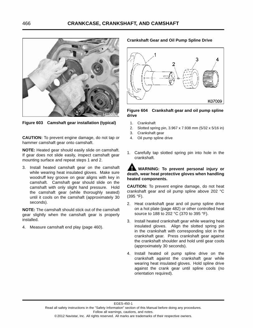
466 CRANKCASE, CRANKSHAFT, AND CAMSHAFT
Figure 603 Camshaft gear installation (typical)
CAUTION: To prevent engine damage, do not tap orhammer camshaft gear onto camshaft.
NOTE: Heated gear should easily slide on camshaft.If gear does not slide easily, inspect camshaft gearmounting surface and repeat steps 1 and 2.
3. Install heated camshaft gear on the camshaftwhile wearing heat insulated gloves. Make surewoodruff key groove on gear aligns with key incamshaft. Camshaft gear should slide on thecamshaft with only slight hand pressure. Holdthe camshaft gear (while thoroughly seated)until it cools on the camshaft (approximately 30seconds).
NOTE: The camshaft should stick out of the camshaftgear slightly when the camshaft gear is properlyinstalled.
4. Measure camshaft end play (page 460).
Crankshaft Gear and Oil Pump Spline Drive
Figure 604 Crankshaft gear and oil pump splinedrive
1. Crankshaft2. Slotted spring pin, 3.967 x 7.938 mm (5/32 x 5/16 in)3. Crankshaft gear4. Oil pump spline drive
1. Carefully tap slotted spring pin into hole in thecrankshaft.
WARNING: To prevent personal injury ordeath, wear heat protective gloves when handlingheated components.
CAUTION: To prevent engine damage, do not heatcrankshaft gear and oil pump spline above 202 °C(395 °F).
2. Heat crankshaft gear and oil pump spline driveon a hot plate (page 482) or other controlled heatsource to 188 to 202 °C (370 to 395 °F).
3. Install heated crankshaft gear while wearing heatinsulated gloves. Align the slotted spring pinin the crankshaft with corresponding slot in thecrankshaft gear. Press crankshaft gear againstthe crankshaft shoulder and hold until gear cools(approximately 30 seconds).
4. Install heated oil pump spline drive on thecrankshaft against the crankshaft gear whilewearing heat insulated gloves. Hold spline driveagainst the crank gear until spline cools (noorientation required).
EGES-450-1Read all safety instructions in the "Safety Information" section of this Manual before doing any procedures.
Follow all warnings, cautions, and notes.©2012 Navistar, Inc. All rights reserved. All marks are trademarks of their respective owners.

CRANKCASE, CRANKSHAFT, AND CAMSHAFT 467
Upper Main Bearings and Crankshaft Assembly
Figure 605 Thrust bearing installation
1. Rotate crankcase so main bearing saddles arefacing up.
2. Clean oil off crankcase main bearing saddles witha lint-free cloth. Do not lubricate the back side ofmain bearings.
3. Install thrust main bearing in the rear #7 uppermain bearing saddle. Make sure locking tab onbearing aligns with notch in the crankcase.
4. Install the remaining six upper main bearings intheir corresponding saddles. Make sure lockingtab on each bearing aligns with notch in thecrankcase.
5. Apply marker paste Prussian Blue (page 482) orequivalent) on the crankshaft main bearingjournals.
EGES-450-1Read all safety instructions in the "Safety Information" section of this Manual before doing any procedures.
Follow all warnings, cautions, and notes.©2012 Navistar, Inc. All rights reserved. All marks are trademarks of their respective owners.

468 CRANKCASE, CRANKSHAFT, AND CAMSHAFT
Figure 606 Crankshaft assembly installation
WARNING: To prevent personal injury ordeath, use a correct size lifting sling and hoistwith a safety latch on hook.
CAUTION: To prevent engine or vehicle damage, donot drop, bend, or gouge crankshaft.
6. Install and center an appropriate lifting sling onthe crankshaft, supported by two connecting rodjournals.
7. Carefully lift and lower the crankshaft onto theupper main bearings in the crankcase.
NOTE: Do not install the main bearing caps at thistime.
8. Rotate the crankshaft 180 degrees (½ turn).
9. Carefully remove the crankshaft and inspect theupper bearings for an even transfer of bluingagent from the journals to the bearings.
• If voids appear in the bluing agent transfer,inspect and measure the crankcase andcrankshaft. Correct any problems and thenrepeat steps 7 through 13.
• If the bluing agent transfer is even and normaland the crankcase and crankshaft are notdamaged then proceed to step 10.
10. Clean all marker paste off bearings and crankshaftjournals.
11. Lubricate upper main bearings with clean engineoil.
12. Install and center an appropriate lifting sling onthe crankshaft, supported by two connecting rodjournals.
13. Carefully lift and lower the crankshaft onto themain bearings in the crankcase.
EGES-450-1Read all safety instructions in the "Safety Information" section of this Manual before doing any procedures.
Follow all warnings, cautions, and notes.©2012 Navistar, Inc. All rights reserved. All marks are trademarks of their respective owners.

CRANKCASE, CRANKSHAFT, AND CAMSHAFT 469
Main Bearing Fit Procedure
Figure 607 Main bearing cap and lower mainbearing
1. Main bearing cap notch2. Bearing alignment tab
NOTE: Main bearing caps and the back of mainbearing surfaces must be free of oil and dirt. Do notlubricate the backside of main bearings.
1. Install lower main bearing in each main bearingcap. Make sure bearing alignment tabs snap ineach bearing cap notch.
Figure 608 Main bearing cap and crankcasestamps (typical)
1. Crankcase stamp for #7 main bearing2. Main bearing cap stamp on #7 main bearing cap3. M15 x 162 main bearing cap bolt (14)
2. Orient each main bearing cap with its matchingcrankcase stamp.
3. Clean each lower main bearing surface and theexposed half of the crankshaft journal. Thesesurfaces must be free of oil.
4. Install each main bearing cap assembly. Lightlyoil threads of new main bearing bolts with cleanengine oil.
NOTE: Bearing clearance measurement checksbearing fit and will not permanently stretch mainbearing bolts. Do not torque-to-yield main bearingbolts until final assembly.
EGES-450-1Read all safety instructions in the "Safety Information" section of this Manual before doing any procedures.
Follow all warnings, cautions, and notes.©2012 Navistar, Inc. All rights reserved. All marks are trademarks of their respective owners.

470 CRANKCASE, CRANKSHAFT, AND CAMSHAFT
Figure 609 Main bearing cap bolt torque sequence
5. Tighten each main bearing cap bolt to 136 N·m(100 lbf·ft) using main bearing cap bolt torquesequence.
6. Tighten each main bearing bolt to 177 N·m(130 lbf·ft) using main bearing cap bolt torquesequence.
7. Remove one main bearing cap assembly at atime. Leave other caps tight.
8. Wipe oil from all contact surfaces of the exposedcrankshaft journal and main bearing.
NOTE: For in chassis service only: the crankshaftmust be supported and held against the upper mainbearing halves to get a correct Plastigage (page482) reading. Use a jack to support the crankshaft atthe counterweight nearest each main bearing beingchecked. Failure to support the crankshaft will resultin inaccurate readings.
NOTE: Do not rotate the crankshaft.
9. Place a piece of Plastigage across the full width ofthe bearing surface on the crankshaft journal (orbearing insert) approximately 6 mm (0.25 in) offcenter. Install the bearing cap and tighten mainbearing cap bolts to 177 N·m (130 lbf·ft).
10. Remove main bearing cap assembly. Do notdisturb the Plastigage.
Figure 610 Plastigage Measurement
11. Measure Plastigage using the scale on thePlastigage envelope. Measure and recordthe widest point of the flattened Plastigage.This reading indicates the bearing clearance inthousandths of an inch or millimeters.
12. Remove Plastigage, install main bearing capassembly, and tighten main bearing bolts to 177N·m (130 lbf·ft). Repeat steps 7 through 11 for allseven main bearings.
13. If main bearing to crankshaft running clearancesare not within Specifications (page 478), replacethe crankshaft or resurface the crankshaft andinstall oversize main bearings.
EGES-450-1Read all safety instructions in the "Safety Information" section of this Manual before doing any procedures.
Follow all warnings, cautions, and notes.©2012 Navistar, Inc. All rights reserved. All marks are trademarks of their respective owners.

CRANKCASE, CRANKSHAFT, AND CAMSHAFT 471
Main Bearings and Caps
Figure 611 Main bearings and caps
1. Rounded end of main bearingcaps
2. Main bearing cap #1 (front ofengine)
3. Upper main bearing4. Lower main bearing5. Crankshaft #1 main bearing
journal
6. M15 x 162 main bearing cap bolt(14)
CAUTION: To prevent engine damage, use new mainbearing cap bolts whenever main bearing cap boltsthat have been torqued to yield are removed.
NOTE: Thrust main bearing is only located on thecrankcase number 7 upper main bearing saddle. Allseven lower bearings are the same part number.
1. Clean all Plastigage and marker paste from mainbearing and crankshaft journal surfaces.
2. Coat all main bearing journal surfaces with cleanengine oil.
3. Lightly coat new main bearing cap bolts with cleanengine oil (coat threads and under bolt head).
NOTE: Main bearing cap rounded ends go toward thecam or exhaust side of the crankcase. Match theupper and lower main bearing tabs on the cam sideof the engine.
CAUTION: To prevent engine damage, match andorient each main bearing cap with its correspondingnumber stamped in the crankcase. Install #1 mainbearing cap on the front main bearing journal andinstall remaining main bearing caps numbered fromthe front of the engine to the rear (number 7).
4. Install seven main bearing cap assemblies in theircorresponding crankcase saddles. Make surenumber on each bearing cap is correctly orientedand matches its corresponding number stampedin the crankcase.
5. Install fourteen new M15 x 162 main bearing capbolts and finger tighten. See Torque Procedurefor Torque-to-yield Main Bearing Cap Bolts (page472).
EGES-450-1Read all safety instructions in the "Safety Information" section of this Manual before doing any procedures.
Follow all warnings, cautions, and notes.©2012 Navistar, Inc. All rights reserved. All marks are trademarks of their respective owners.

472 CRANKCASE, CRANKSHAFT, AND CAMSHAFT
Torque Procedure for Torque-to-yield MainBearing Cap Bolts
Figure 612 Main bearing cap bolt torque sequence
1. Tighten each main bearing cap bolt to 136 N·m(100 lbf·ft) using main bearing cap bolt torquesequence.
2. Measure crankshaft end play (page 461). Do notproceed to the next step in this procedure until endplay is within Specification (page 478).
3. Tighten each main bearing cap bolt to 177 N·m(130 lbf·ft) using main bearing cap bolt torquesequence.
Figure 613 Main bearing cap bolt torque-to-yieldmarking
1. Head of main bearing cap bolt before Torque-to-yield2. Head of main bearing cap bolt after Torque-to-yield3. Mark on main bearing cap surface
CAUTION: To prevent engine damage, use new mainbearing cap bolts whenever main bearing cap boltsthat have been torqued to yield are removed.
CAUTION: To prevent engine damage, usepermanent marker to identify internal enginecomponents and their orientation. Do not use paintor temporary markers.
4. Using a permanent marker, place a mark on eachnew main bearing cap bolt and put another markon the socket directly in line with the mark on eachnew main bearing cap bolt.
5. Put a mark on the main bearing cap surface 90°clockwise from each main bearing cap bolt mark.
6. Install socket on main bearing cap bolt to betorqued and align mark on socket with the markon the main bearing cap bolt.
7. Torque-to-yield each main bearing cap bolt byrotating each bolt 90 degrees clockwise (1/4 turn).The marks on the socket, main bearing cap bolt,and main bearing cap surface should be aligned.
EGES-450-1Read all safety instructions in the "Safety Information" section of this Manual before doing any procedures.
Follow all warnings, cautions, and notes.©2012 Navistar, Inc. All rights reserved. All marks are trademarks of their respective owners.
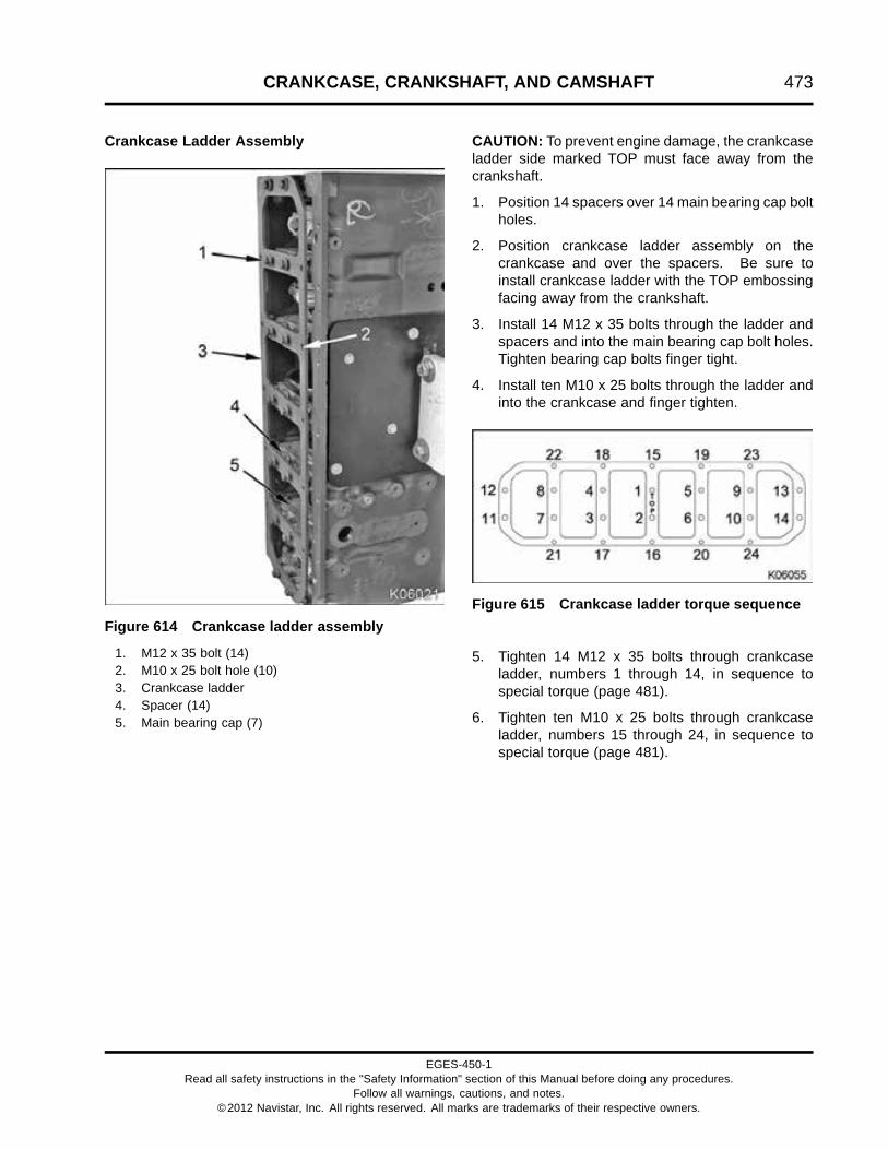
CRANKCASE, CRANKSHAFT, AND CAMSHAFT 473
Crankcase Ladder Assembly
Figure 614 Crankcase ladder assembly
1. M12 x 35 bolt (14)2. M10 x 25 bolt hole (10)3. Crankcase ladder4. Spacer (14)5. Main bearing cap (7)
CAUTION: To prevent engine damage, the crankcaseladder side marked TOP must face away from thecrankshaft.
1. Position 14 spacers over 14 main bearing cap boltholes.
2. Position crankcase ladder assembly on thecrankcase and over the spacers. Be sure toinstall crankcase ladder with the TOP embossingfacing away from the crankshaft.
3. Install 14 M12 x 35 bolts through the ladder andspacers and into the main bearing cap bolt holes.Tighten bearing cap bolts finger tight.
4. Install ten M10 x 25 bolts through the ladder andinto the crankcase and finger tighten.
Figure 615 Crankcase ladder torque sequence
5. Tighten 14 M12 x 35 bolts through crankcaseladder, numbers 1 through 14, in sequence tospecial torque (page 481).
6. Tighten ten M10 x 25 bolts through crankcaseladder, numbers 15 through 24, in sequence tospecial torque (page 481).
EGES-450-1Read all safety instructions in the "Safety Information" section of this Manual before doing any procedures.
Follow all warnings, cautions, and notes.©2012 Navistar, Inc. All rights reserved. All marks are trademarks of their respective owners.

474 CRANKCASE, CRANKSHAFT, AND CAMSHAFT
Coolant Heater Assembly (Optional)
Figure 616 Coolant heater assembly
1. Heater element2. Cord adaptor3. O-ring
1. Lubricate a new O-ring with clean coolant andinstall on the coolant heater assembly.
Figure 617 Coolant heater (intake side ofcrankcase)
1. Coolant heater mounting flange2. M8 x 20 bolt
2. Install coolant heater element into the crankcase.Press coolant heater mounting flange flush withcrankcase mounting surface.
3. Tighten M8 x 20 bolt to standard torque (page523).
4. Refill cooling system and check for leaks.
EGES-450-1Read all safety instructions in the "Safety Information" section of this Manual before doing any procedures.
Follow all warnings, cautions, and notes.©2012 Navistar, Inc. All rights reserved. All marks are trademarks of their respective owners.

CRANKCASE, CRANKSHAFT, AND CAMSHAFT 475
Oil Level Gauge Assembly
Figure 618 Oil level gauge tube
1. If removed, install oil level gauge tube incrankcase. Apply Loctite® 277™ (page482) around entire outside circumference of tube.Drive oil level gauge tube into crankcase untilbead of tube is seated in chamfer of crankcaseboss (tube orientation is not required).
Figure 619 Oil filler tube support
1. M6 x 16 bolt2. M8 nut (2)
NOTE: If oil filler tube support was removed, do steps2 through 8. If oil filler tube support was not removed,go to step 5.
2. Install oil filler tube support and two M8 nuts onthe fuel filter header assembly mounting studs.
3. Install M6 x 16 bolt and tighten to special torque(page 481).
4. Tighten two M8 nuts to special torque.
Figure 620 Oil level gauge assembly
1. Cushioned clamp2. Oil filler tube support3. Oil level gauge tube4. Tube clamp5. Oil filler tube6. M6 x 25 bolt and M6 nut
5. Install oil filler tube and tube clamp on the oil levelgauge tube.
6. Install cushioned clamp on the oil filler tube andinstall the M6 x 25 bolt through the cushionedclamp and oil filler tube support. Install M6 nuton M6 x 25 bolt
7. Tighten tube clamp.
8. Tighten M6 x 25 bolt and nut to special torque(page 481).
EGES-450-1Read all safety instructions in the "Safety Information" section of this Manual before doing any procedures.
Follow all warnings, cautions, and notes.©2012 Navistar, Inc. All rights reserved. All marks are trademarks of their respective owners.

476 CRANKCASE, CRANKSHAFT, AND CAMSHAFT
Crankcase Ventilation System
Figure 621 Crankcase breather assembly backplate and seal
1. Housing assembly (turbine)2. Breather to crankcase seal
1. Lubricate a new breather to crankcase seal withclean engine oil and install into the back plate ofthe crankcase breather assembly.
NOTE: Two different size bolts secure the crankcasebreather assembly to the crankcase. There are threeM8 x 30 bolts securing the two bottom and middle rightside of the crankcase breather assembly as well assecuring the coolant return tube supports. The otherthree bolts are M8 x 25, secure the crankcase breatherassembly to the crankcase. The correct bolts must beplaced in the correct locations to correctly secure thecrankcase breather assembly to the crankcase.
2. Install crankcase breather assembly to thecrankcase and secure with three M8 x 25 bolts.Finger tighten bolts.
3. Lubricate two new coolant return tube O-rings withclean coolant and install onto coolant return tubeassembly ends.
4. Install the coolant return tube assembly into the oilcooler module and coolant supply housing.
5. Use the three M8 x 30 bolts and secure thecoolant return tube supports and the crankcasebreather assembly to the crankcase. Fingertighten bolts.
6. Tighten six M8 bolts, securing the crankcasebreather to the crankcase, see special torque(page 481).
Figure 622 Crankcase breather assembly andinlet tube
1. Port elbow2. Crankcase breather outlet tube3. Crankcase breather inlet tube4. Crankcase breather inlet tube hose clamp (2)5. Crankcase breather assembly with turbine6. Coolant return tube assembly (two tubes and
interconnecting hose)7. High and low-pressure turbo drain tube hose clamp
(4)8. High-pressure turbo drain hose9. Low-pressure turbo drain hose10. Oil cooler module11. Breather elbow12. Crankcase breather outlet tube hose clamp (2)13. High and low-pressure turbo drain tube clamp14. M8 x 25 bolt
EGES-450-1Read all safety instructions in the "Safety Information" section of this Manual before doing any procedures.
Follow all warnings, cautions, and notes.©2012 Navistar, Inc. All rights reserved. All marks are trademarks of their respective owners.

CRANKCASE, CRANKSHAFT, AND CAMSHAFT 477
7. Install new O-rings onto the high and low-pressureturbo drain tubes.
8. Install high and low-pressure turbo drain tubesinto the high and low-pressure turbochargers.
9. Loosely place hose clamps over drain tubes andinstall both high and low-pressure turbo draintubes onto hoses.
10. Tighten hose clamps securing high andlow-pressure turbocharger drain tubes to hoses.
11. Install high and low-pressure turbo drain tubeclamp over tube and secure to the EGR coolerwith an M8 x 25 bolt. Finger tighten bolt
12. Tighten M8 x 25 bolt to standard torque (page523).
13. Loosely place hose clamp over the breather outlettube. Install breather outlet tube onto port elbow.
14. Loosely place hose clamp over the breather outlettube. Install breather outlet tube onto breatherelbow.
15. Tighten both the port elbow and breather elbowhose clamps.
16. Loosely place hose clamp over breather inlettube. Install breather inlet tube onto inlet elbow.
17. Tighten the inlet elbow hose clamp securing theinlet tube to the inlet elbow.
EGES-450-1Read all safety instructions in the "Safety Information" section of this Manual before doing any procedures.
Follow all warnings, cautions, and notes.©2012 Navistar, Inc. All rights reserved. All marks are trademarks of their respective owners.

478 CRANKCASE, CRANKSHAFT, AND CAMSHAFT
Specifications
Crankcase Specifications
Main cap attachment 2 bolts per main cap
Main bearing type Precision replaceable
Main bearing material Steel-backed copper, lead, tin
Thrust taken by Rear upper main bearing #7
Engine block heater rating 1250 W, 120 V
Center line of main bearing bore to head deck 368.3 ± 0.05 mm (14.50 ± 0.002 in)
Counterbore depth allowable variation between four points(maximum)
0.025 mm (0.001 in)
Counterbore depth in crankcase 8.865 ± 0.025 mm (0.349 ± 0.001 in)
Counterbore diameter in crankcase 136.14 + 0.381 – 0.127 mm (5.360 +0.015 – 0.005 in)
Counterbore maximum allowable depth 9.25 mm (0.364 in)
Crankcase deck flatness 0.076 mm (0.003 in)
Crankcase main bearing bore diameter 116.421 ± 0.127 mm (4.5835 ± 0.005 in)
Piston cooling tube diameter (spray hole) MaxxForce® DT 2.18 mm (0.086 in)
Piston cooling tube diameter (spray hole) MaxxForce® 9 and 10 2.59 mm (0.102 in)
Roller tappet outside diameter 28.435 to 28.448 mm (1.1195 to 1.1200 in)
Sleeve protrusion above crankcase 0.051 to 0.127 mm (0.002 to 0.005 in)
Tappet bore diameter 28.5306 ± 0.01905 mm (1.12325 ±0.00075 in)
Camshaft Bearing Bore Diameter in Crankcase:
Front 63.5521 ± 0.01905 mm (2.50205 ±0.00075 in)
Intermediate (2) 63.0238 ± 0.01905 mm (2.48125 ±0.00075 in)
Rear 63.5521 ± 0.01905 mm (2.50205 ±0.00075 in)
EGES-450-1Read all safety instructions in the "Safety Information" section of this Manual before doing any procedures.
Follow all warnings, cautions, and notes.©2012 Navistar, Inc. All rights reserved. All marks are trademarks of their respective owners.

CRANKCASE, CRANKSHAFT, AND CAMSHAFT 479
Camshaft Specifications
Camshaft bearing inner diameter (ID) (installed) 58.04 to 58.12 mm (2.285 to 2.288 in)
Cam lobe lift, exhaust 6.91 mm (0.272 in)
Cam lobe lift, intake 6.68 mm (0.263 in)
Camshaft end play 0.18 to 0.33 mm (0.007 to 0.013 in)
Camshaft journal diameter 57.96 to 57.99 mm (2.282 to 2.283 in)
Camshaft journal to bearing radial clearance 0.025 to 0.076 mm (0.001 to 0.003 in)
Maximum permissible cam lobe wear 0.25 mm (0.010 in)
Service bearings furnished to size Yes
Thrust plate thickness (new) 6.96 to 7.01 mm (0.274 to 0.276 in)
Camshaft Bearing Specifications
Bearing Location Outside Diameter (nominal) Width (nominal)
Front 63.5 mm (2.50 in) 25.4 mm (1.00 in)
Rear 63.5 mm (2.50 in) 17.8 mm (0.70 in)
Intermediate 63.0 mm (2.48 in) 26.7 mm (1.05 in)
EGES-450-1Read all safety instructions in the "Safety Information" section of this Manual before doing any procedures.
Follow all warnings, cautions, and notes.©2012 Navistar, Inc. All rights reserved. All marks are trademarks of their respective owners.

480 CRANKCASE, CRANKSHAFT, AND CAMSHAFT
Crankshaft Specifications
Crankshaft Forged steel, induction hardened, grindable
Number of main bearings 7
Thrust taken by Number 7 rear upper main bearing
Main bearing journal diameter:
Standard size 107.95 ± 0.015 mm (4.250 ± 0.0006 in)
0.254 mm (0.010 in) undersized 107.70 ± 0.015 mm (4.240 ± 0.0006 in)
0.508 mm (0.020 in) undersized 107.44 ± 0.015 mm (4.230 ± 0.0006 in)
0.762 mm (0.030 in) undersized 107.19 ± 0.015 mm (4.220 ± 0.0006 in)
Crankshaft journal waviness (maximum) 0.00381 mm (0.00015 in)
Crankshaft journal surface finish 0.00015 mm (0.000006 in)
NOTE: Grind all crankshaft journals against operating rotation (when looking at front end of crankshaft,operating rotation is clockwise). Lap all Journals with operating rotation, not more than 0.0127 mm (0.0005in) stock to be removed by lapping.
Thrust Bearing Journal Length:
Standard size to 0.76 mm (0.030 in) undersized 34.404 ± 0.546 mm (1.3545 ± 0.0015 in)
Connecting rod journal diameter:
Standard size 80.010 ± 0.015 mm (3.1500 ± 0.0006 in)
0.0254 mm (0.010 in) undersized 79.756 ± 0.015 mm (3.1400 ± 0.0006 in)
0.508 mm (0.020 in) undersized 79.502 ± 0.015 mm (3.1300 ± 0.0006 in)
0.762 mm (0.030 in) undersized 79.248 ± 0.015 mm (3.1200 ± 0.0006 in)
EGES-450-1Read all safety instructions in the "Safety Information" section of this Manual before doing any procedures.
Follow all warnings, cautions, and notes.©2012 Navistar, Inc. All rights reserved. All marks are trademarks of their respective owners.

CRANKCASE, CRANKSHAFT, AND CAMSHAFT 481
Crankshaft Specifications (continued)
Connecting rod bearing to crankshaft running clearance 0.030 to 0.107 mm (0.0012 to 0.0042 in)
Connecting rod bearing width 39.99 mm (1.5745 in)
Connecting rod journal maximum out-of-round 0.0064 mm (0.00025 in)
Connecting rod journal taper (maximum per inch) 0.0051 mm (0.0002 in)
Connecting rod to crankshaft side clearance 0.190 to 0.419 mm (0.0075 to 0.0165 in)
Crankshaft end play 0.152 to 0.305 mm (0.006 to 0.012 in)
Crankshaft end play maximum wear limit 0.51 mm (0.020 in)
Crankshaft flange outside diameter 155.58 mm (6.125 in)
Damper mounting surface runout (maximum) 0.0127 mm (0.0005 in)
Flywheel mounting surface runout (maximum) 0.05 mm (0.002 in)
Main bearing journal maximum out-of-round 0.00635 mm (0.00025 in)
Main bearing journal taper (maximum per inch) 0.0051 mm (0.0002 in)
Main bearing thrust face runout (TIR maximum) 0.026 mm (0.001 in)
Main bearing to crankshaft running clearance 0.046 to 0.127 mm (0.0018 to 0.0050 in)
Main bearing width (except rear thrust) 34.19 ± 0.13 mm (1.346 ± 0.005 in)
Rear oil seal journal runout (maximum) 0.08 mm (0.003 in)
Special Torque
Crankcase breather assembly to crankcase M8 x 25and M8 x 30 bolts
27 N·m (20 lbf·ft)
Crankcase ladder, M12 x 35 122 N·m (90 lbf·ft)
Crankcase ladder, M10 x 25 63 N·m (46 lbf·ft)
Main bearing cap bolt torque and sequence See Torque Procedure for Torque-to-yield MainBearing Cap Bolts (page 472)
M12 tee assembly 24 N·m (18 lbf·ft)
Oil filler tube support bolt, M6 x 16 13.6 N·m (120 lbf·in)
Oil filler tube support, M8 nuts 34 N·m (25 lbf·ft)
Oil filler tube support, M6 x 25 bolt and M6 nut 13.6 N·m (120 lbf·in)
EGES-450-1Read all safety instructions in the "Safety Information" section of this Manual before doing any procedures.
Follow all warnings, cautions, and notes.©2012 Navistar, Inc. All rights reserved. All marks are trademarks of their respective owners.

482 CRANKCASE, CRANKSHAFT, AND CAMSHAFT
Special Service Tools
Cam Gear Puller ZTSE4411
Camshaft Bearing Puller ZTSE2893B
Dial indicator set Obtain locally
Dye penetrant kit Obtain locally
Hot plate Obtain locally
Loctite® 262 Obtain locally
Loctite® 277 Obtain locally
Outside micrometer Obtain locally
Plastigage Obtain locally
Prussian Blue Obtain locally
Stiff Nylon Brush ZTSE4392
Tap Set ZTSE4386
EGES-450-1Read all safety instructions in the "Safety Information" section of this Manual before doing any procedures.
Follow all warnings, cautions, and notes.©2012 Navistar, Inc. All rights reserved. All marks are trademarks of their respective owners.

ABBREVIATIONS AND ACRONYMS 483
Table of Contents
Abbreviations and Acronyms.. . . . . . . . . . . . . . . . . . . . . . . . . . . . . . . . . . . . . . . . . . . . . . . . . . . . . . . . . . . . . . . . . . . . . . . . . . . . . . . . . . . . . . .485Abbreviations and Acronyms.. . . . . . . . . . . . . . . . . . . . . . . . . . . . . . . . . . . . . . . . . . . . . . . . . . . . . . . . . . . . . . . . . . . . . . . . . . . . .485
EGES-450-1Read all safety instructions in the "Safety Information" section of this Manual before doing any procedures.
Follow all warnings, cautions, and notes.©2012 Navistar, Inc. All rights reserved. All marks are trademarks of their respective owners.

484 ABBREVIATIONS AND ACRONYMS
EGES-450-1Read all safety instructions in the "Safety Information" section of this Manual before doing any procedures.
Follow all warnings, cautions, and notes.©2012 Navistar, Inc. All rights reserved. All marks are trademarks of their respective owners.

ABBREVIATIONS AND ACRONYMS 485
Abbreviations and AcronymsAbbreviations and Acronyms
A or amp – AmpereAAT – Ambient Air TemperatureABDC – After Bottom Dead CenterABS – Antilock Brake SystemAC – Alternating CurrentA/C – Air ConditionerACC – Air Conditioner ControlACCEL – AccelerateACD – Air Conditioner DemandACM – Aftertreatment Control ModuleACT PWR GND – Actuator Power GroundACV – Air Control ValveAF – Air to Fuel ratioAFT – AftertreatmentAFTFD – Aftertreatment Fuel DoserAFTFDH – Aftertreatment Fuel Doser HighAFTFDL – Aftertreatment Fuel Doser LowAFTFIT – Aftertreatment Fuel Inlet TemperatureAFTFIS – Aftertreatment Fuel Inlet SensorAFTFP – Aftertreatment Fuel PressureAFTFP1 – Aftertreatment Fuel Pressure 1AFTFP2 – Aftertreatment Fuel Pressure 2AFTFSH – Aftertreatment Fuel Shutoff HighAFTFSL – Aftertreatment Fuel Shutoff LowAFTFSV – Aftertreatment Fuel Shutoff ValveAIT – Air Inlet TemperatureAmb – Ambientamp or A – AmpereAMS – Air Management SystemAPI – American Petroleum InstituteAPP – Accelerator Pedal PositionAPP1 – Accelerator Pedal Position 1APP2 – Accelerator Pedal Position 2ASTM – American Society for Testing and MaterialsATA – American Trucking AssociationATAH – American Trucking Association Link HighATAL – American Trucking Association Link LowATDC – After Top Dead CenterAWG – American Wire GaugeB+ or VBAT – Battery VoltageBARO – Barometric Absolute PressureBBDC – Before Bottom Dead CenterBDC – Bottom Dead Centerbhp – Brake HorsepowerBOO – Brake On / OffBPP – Brake Pedal PositionBPS – Brake Pressure SwitchBTDC – Before Top Dead Center
BTU – British Thermal UnitC – CelsiusCAC – Charge Air CoolerCACOT – Charge Air Cooler Outlet TemperatureCAN – Controller Area NetworkCAP – Cold Ambient ProtectionCARB – California Air Resources Boardcc – Cubic centimeterCCA – Cold Cranking AmpereCCOSS – Crankcase Oil Separator Speedcfm – Cubic feet per minutecfs – Cubic feet per secondCFV – Coolant Flow ValveCID – Cubic Inch DisplacementCKP – Crankshaft PositionCKPH – Crankshaft Position HighCKPL – Crankshaft Position LowCKPO – Crankshaft Position Outcm – CentimeterCMP – Camshaft PositionCMPH – Camshaft Position HighCMPL – Camshaft Position LowCMPO – Camshaft Position OutCMV – Coolant Mixer ValveCO – Carbon MonoxideCOO – Cruise On / Off switchCPU – Central Processing UnitCSFI – Cold Start Fuel IgniterCSFS – Cold Start Fuel SolenoidCSR – Cold Start RelayCTC – Coolant Temperature CompensationCyl – CylinderDB – DecibelDCA – Diesel Coolant AdditiveDDI – Digital Direct Fuel InjectionDDS – Driveline Disengagement SwitchDLC – Data Link ConnectorDME – Dimethyl EtherDMM – Digital Multi-meterDOC – Diesel Oxidation CatalystDOCIT – Diesel Oxidation Catalyst Inlet TemperatureDOCOT – Diesel Oxidation Catalyst OutletTemperatureDPF – Diesel Particulate FilterDPFDP – Diesel Particulate Filter DifferentialPressureDPFIT – Diesel Particulate Filter Inlet TemperatureDPFOT – Diesel Particulate Filter Outlet TemperatureDSI – Down Stream InjectionDT – Diesel TurbochargedDTC – Diagnostic Trouble Code
EGES-450-1Read all safety instructions in the "Safety Information" section of this Manual before doing any procedures.
Follow all warnings, cautions, and notes.©2012 Navistar, Inc. All rights reserved. All marks are trademarks of their respective owners.

486 ABBREVIATIONS AND ACRONYMS
DTRM – Diesel Thermo Recirculation ModuleEBP – Exhaust Back PressureEBPD – Exhaust Back Pressure DesiredEBPV – Exhaust Back Pressure ValveECB – Engine Compression BrakeECB1 – Engine Compression Brake 1ECB2 – Engine Compression Brake 2ECBP – Engine Compression Brake PressureECI – Engine Crank InhibitECL – Engine Coolant LevelECM – Engine Control ModuleECM GND – Engine Control Module GroundECM PWR – Engine Control Module PowerECS – Engine Coolant SystemECSR – Engine Controlled Shutdown RequestECT – Engine Coolant TemperatureECT1 – Engine Coolant Temperature 1ECT2 – Engine Coolant Temperature 2EFAN – Engine FanEFC – Engine Fan ControlEFRC – Engine Family Rating CodeEFS – Engine Fan SpeedEFT – Engine Fuel TemperatureEG – Ethylene GlycolEGC – Electronic Gauge ClusterEGBP – Exhaust Gas Back PressureEGDP – Exhaust Gas Differential PressureEGR – Exhaust Gas RecirculationEGRC – Exhaust Gas Recirculation ControlEGRH – Exhaust Gas Recirculation High controlEGRL – Exhaust Gas Recirculation Low controlEGROT – Exhaust Gas Recirculation OutletTemperatureEGRP – Exhaust Gas Recirculation PositionEGRT – Exhaust Gas Recirculation TemperatureEGT – Exhaust Gas TemperatureEGT1 – Exhaust Gas Temperature 1EGT2 – Exhaust Gas Temperature 2EGT3 – Exhaust Gas Temperature 3EMI – Electromagnetic InterferenceEMP – Exhaust Manifold PressureEMT – Exhaust Manifold TemperatureEOL – Engine Oil LevelEOP – Engine Oil PressureEOT – Engine Oil TemperatureEPA – Environmental Protection AgencyEPR – Engine Pressure RegulatorESC – Electronic System ControllerESN – Engine Serial NumberEST – Electronic Service ToolETC – Engine Throttle Control
ETCH – Engine Throttle Control HighETCL – Engine Throttle Control LowETP – Engine Throttle PositionETV – Engine Throttle ValveEWPS – Engine Warning Protection SystemF – FahrenheitFCV – Fuel Coolant ValveFDP – Fuel Delivery PressureFEL – Family Emissions Limitfhp – Friction horsepowerFMI – Failure Mode IndicatorFPC – Fuel Pump ControlFPCV – Fuel Pressure Control Valvefpm – Feet per minuteFPM – Fuel Pump Monitorfps – Feet per secondFRP – Fuel Rail Pressureft – FeetFVCV – Fuel Volume Control ValveGND – Ground (electrical)gal – Gallongal/h – U.S. Gallons per hourgal/min – U.S. Gallons per minuteGCW – Gross Combined WeightGCWR – Gross Combined Weight RatingGPC – Glow Plug ControlGPD – Glow Plug DiagnosticGPR – Glow Plug RelayGVW – Gross Vehicle WeightH2O – WaterHC – HydrocarbonsHEST – High Exhaust System TemperatureHFCM – Horizontal Fuel Conditioning ModuleHg – Mercuryhp – HorsepowerHPCAC – High-Pressure Charge Air CoolerHPCR – High-Pressure Common RailHPFP – High-Pressure Fuel Pumphr – HourHS – Humidity SensorHyd – HydraulicIAH – Inlet Air HeaterIAHC – Inlet Air Heater ControlIAHD – Inlet Air Heater DiagnosticIAHR – Inlet Air heater RelayIC – Integrated CircuitICP – Injection Control PressureICPR – Injection Control Pressure RegulatorICG1 – Injector Control Group 1ICG2 – Injector Control Group 2ID – Inside Diameter
EGES-450-1Read all safety instructions in the "Safety Information" section of this Manual before doing any procedures.
Follow all warnings, cautions, and notes.©2012 Navistar, Inc. All rights reserved. All marks are trademarks of their respective owners.

ABBREVIATIONS AND ACRONYMS 487
IGN – IgnitionILO – Injector Leak OffIMP – Intake Manifold PressureIMT – Intake Manifold Temperaturein – InchinHg – Inch of mercuryinH2O – Inch of waterINJs – InjectorsIPR – Injection Pressure RegulatorIPR PWR – Injection Pressure Regulator PowerISC – Interstage CoolerISIS – International® Service Information SystemIST – Idle Shutdown TimerITP – Internal Transfer PumpJ1939H – J1939 Data Link HighJ1939L – J1939 Data Link LowJCT – Junction (electrical)kg – Kilogramkm – Kilometerkm/h – Kilometers per hourkm/l – Kilometers per literKOEO – Key-On Engine-OffKOER – Key-On Engine-RunningkPa – KilopascalL – LiterL/h – Liters per hourL/m – Liters per minuteL/s – Liters per secondlb – Poundlbf – Pounds of forcelb/s – Pounds per secondlbf ft – Pounds of force per footlbf in – Pounds of force per inchlbm – Pounds of massLSD – Low Sulfur Dieselm – Meterm/s – Meters per secondMAF – Mass Air FlowMAF GND – Mass Air Flow GroundMAG – MagneticMAP – Manifold Absolute PressureMAT – Manifold Air Temperaturemep – Mean effective pressuremi – MileMIL – Malfunction Indicator Lampmm – Millimetermpg – Miles per gallonmph – Miles per hourMPR – Main Power RelayMSDS – Material Safety Data SheetMSG – Micro Strain Gauge
MSM – Multiplex System ModuleMY – Model YearNC – Normally closed (electrical)NETS – Navistar Electronics Technical SupportNm – Newton meterNO – Normally Open (electrical)NOX – Nitrogen OxidesO2S – Oxygen SensorO2SH – Oxygen Sensor HeaterOAT – Organic Acid TechnologyOCC – Output Circuit CheckOCP – Overcrank ProtectionOD – Outside DiameterOL – Over LimitORH – Out-of-Range HighORL – Out-of-Range LowOSHA – Occupational Safety and HealthAdministrationOWL – Oil/Water LampPID – Parameter IdentifierP/N – Part NumberPDOC – Pre-Diesel Oxidation Catalystppm – Parts per millionPROM – Programmable Read Only Memorypsi – Pounds per square inchpsia – Pounds per square inch absolutepsig – Pounds per square inch gaugept – PintPTO – Power TakeoffPWM – Pulse Width ModulatePWR – Power (voltage)qt – QuartRAM – Random Access MemoryRAPP – Remote Accelerator Pedal PositionRAS – Resume / Accelerate Switch (speed control)REPTO – Rear Engine Power TakeoffRFI – Radio Frequency Interferencerev – Revolutionrpm – Revolutions per minuteRPRE – Remote Preset Power Take OffRSE – Radiator Shutter EnableRVAR – Remote VariableSAE – Society of Automotive Engineers®SCA – Supplemental Cooling AdditiveSCCS – Speed Control Command SwitchesSCS – Speed Control SwitchSHD – Shield (electrical)SID – Subsystem IdentifierSIG GND – Signal GroundSIG GNDB – Signal Ground BodySIG GNDC – Signal Ground Chassis
EGES-450-1Read all safety instructions in the "Safety Information" section of this Manual before doing any procedures.
Follow all warnings, cautions, and notes.©2012 Navistar, Inc. All rights reserved. All marks are trademarks of their respective owners.
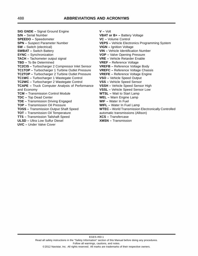
488 ABBREVIATIONS AND ACRONYMS
SIG GNDE – Signal Ground EngineS/N – Serial NumberSPEEDO – SpeedometerSPN – Suspect Parameter NumberSW – Switch (electrical)SWBAT – Switch BatterySYNC – SynchronizationTACH – Tachometer output signalTBD – To Be DeterminedTC2CIS – Turbocharger 2 Compressor Inlet SensorTC1TOP – Turbocharger 1 Turbine Outlet PressureTC2TOP – Turbocharger 2 Turbine Outlet PressureTC1WC – Turbocharger 1 Wastegate ControlTC2WC – Turbocharger 2 Wastegate ControlTCAPE – Truck Computer Analysis of Performanceand EconomyTCM – Transmission Control ModuleTDC – Top Dead CenterTDE – Transmission Driving EngagedTOP – Transmission Oil PressureTOSS – Transmission Output Shaft SpeedTOT – Transmission Oil TemperatureTTS – Transmission Tailshaft SpeedULSD – Ultra Low Sulfur DieselUVC – Under Valve Cover
V – VoltVBAT or B+ – Battery VoltageVC – Volume ControlVEPS – Vehicle Electronics Programming SystemVIGN – Ignition VoltageVIN – Vehicle Identification NumberVOP – Valve Opening PressureVRE – Vehicle Retarder EnableVREF – Reference VoltageVREFB – Reference Voltage BodyVREFC – Reference Voltage ChassisVREFE – Reference Voltage EngineVSO – Vehicle Speed OutputVSS – Vehicle Speed SensorVSSH – Vehicle Speed Sensor HighVSSL – Vehicle Speed Sensor LowWTSL – Wait to Start LampWEL – Warn Engine LampWIF – Water In FuelWIFL – Water In Fuel LampWTEC – World Transmission Electronically Controlledautomatic transmissions (Allison)XCS – TransfercaseXMSN – Transmission
EGES-450-1Read all safety instructions in the "Safety Information" section of this Manual before doing any procedures.
Follow all warnings, cautions, and notes.©2012 Navistar, Inc. All rights reserved. All marks are trademarks of their respective owners.

TERMINOLOGY 489
Table of Contents
Terminology.. . . . . . . . . . . . . . . . . . . . . . . . . . . . . . . . . . . . . . . . . . . . . . . . . . . . . . . . . . . . . . . . . . . . . . . . . . . . . . . . . . . . . . . . . . . . . . . . . . . . . . . . . . . .491Terms.. . . . . . . . . . . . . . . . . . . . . . . . . . . . . . . . . . . . . . . . . . . . . . . . . . . . . . . . . . . . . . . . . . . . . . . . . . . . . . . . . . . . . . . . . . . . . . . . . . . . . . . . . .491
EGES-450-1Read all safety instructions in the "Safety Information" section of this Manual before doing any procedures.
Follow all warnings, cautions, and notes.©2012 Navistar, Inc. All rights reserved. All marks are trademarks of their respective owners.

490 TERMINOLOGY
EGES-450-1Read all safety instructions in the "Safety Information" section of this Manual before doing any procedures.
Follow all warnings, cautions, and notes.©2012 Navistar, Inc. All rights reserved. All marks are trademarks of their respective owners.

TERMINOLOGY 491
TerminologyTerms
Accelerator Pedal Position (APP) sensor – Apotentiometer sensor that indicates the position of thethrottle pedal.
Accessory work – The work per cycle requiredto drive engine accessories (normally, only thoseessential to engine operation).
Actuator – A device that performs work in responseto an input signal.
Actuator Control – The ECM controls the actuatorsby applying a low-level signal (low-side driver) or ahigh-level signal (high side driver). When switched on,both drivers complete a ground or power circuit to anactuator.
Aeration – The entrainment of air or combustion gasin coolant, lubricant, or fuel.
Aftercooler (Charge Air Cooler) – A heat exchangermounted in the charge air path between theturbocharger and engine intake manifold. Theaftercooler reduces the charge air temperature bytransferring heat from the charge air to a coolingmedium (usually air).
Aftertreatment Fuel Doser (AFTFD) – A part ofthe Downstream Injection (DSI) unit that sendspressurized fuel to the Aftertreatment Fuel Injector(AFI) to inject fuel into the exhaust pipe.
Aftertreatment (AFT) system – A part of the exhaustsystem that processes engine exhaust to meetemission requirements and traps particulate matter(soot) to prevent it from leaving the tailpipe.
Air Control Valve (ACV) – Contains the LPturbocharger wastegate control port, HP turbochargerwastegate control port, the EBPV control port, andthe TC1TOP port. Although these components areintegral to the ACV, each circuit is controlled by theECM. The ACV controls compressed air for eachcontrol valve.
Air Inlet Temperature (AIT) sensor – A thermistorsensor that monitors intake air temperature.
Ambient temperature – The environmental airtemperature in which a unit is operating. In general,the temperature is measured in the shade (no solarradiation) and represents the air temperature for otherengine cooling performance measurement purposes.
Air entering the radiator may or may not be the sameambient due to possible heating from other sourcesor recirculation. (SAE J1004 SEP81)
Ampere (amp) – The standard unit for measuring thestrength of an electrical current. The flow rate of acharge in a conductor or conducting medium of onecoulomb per second. (SAE J1213 NOV82)
Analog – A continuously variable voltage.
Analog to digital converter (A/D) – A device in theECM that converts an analog signal to a digital signal.
American Trucking Association (ATA) Datalink –A serial datalink specified by the American TruckingAssociation and the SAE.
Boost pressure – 1. The pressure of the charge airleaving the turbocharger.
2. Inlet manifold pressure that is greater thanatmospheric pressure. Obtained by turbocharging.
Bottom Dead Center (BDC) – The lowest position ofthe piston during the stroke.
Brake Horsepower (bhp) – The power output froman engine, not the indicated horsepower. The poweroutput of an engine, sometimes-called flywheelhorsepower, is less than the indicated horsepower bythe amount of friction horsepower consumed in theengine.
Brake Horsepower (bhp) net – Net brakehorsepower is measured with all engine components.The power of an engine when configured as a fullyequipped engine. (SAE J1349 JUN90)
Calibration – ECM programming strategy to solveengine performance equations and make decisions.Calibration values are stored in ROM and put into theprocessor during programming to allow the engine tooperate within certain parameters.
Camshaft Position (CMP) sensor – A magneticpickup sensor that provides the ECM with a camshaftspeed and position signal.
Carbon Monoxide (CO) – A colorless, odorless,highly poisonous gas that is formed by the incompletecombustion of carbon burning diesel engine. It ispresent in the exhaust gases of diesel engines.
Catalyst – A substance that produces a chemicalreaction without undergoing a chemical change itself.
EGES-450-1Read all safety instructions in the "Safety Information" section of this Manual before doing any procedures.
Follow all warnings, cautions, and notes.©2012 Navistar, Inc. All rights reserved. All marks are trademarks of their respective owners.

492 TERMINOLOGY
Catalytic converter – An antipollution device in theexhaust system that contains a catalyst for chemicallyconverting some pollutants in the exhaust gases(carbon monoxide, unburned hydrocarbons, andoxides of nitrogen) into harmless compounds.
Cavitation – A dynamic condition in a fluid system thatforms gas-filled bubbles (cavities) in the fluid.
Cetane number – 1. The auto-ignition quality ofdiesel fuel.
2. A rating applied to diesel fuel similar to octanerating for gasoline.
3. A measure of how readily diesel fuel starts to burn(self-ignites) at high compression temperature.
Diesel fuel with a high cetane number self-ignitesshortly after injection into the combustion chamber.Therefore, it has a short ignition delay time. Dieselfuel with a low cetane number resists self-ignition.Therefore, it has a longer ignition delay time.
Charge air – Dense, pressurized, heated airdischarged from the turbocharger.
Charge Air Cooler (CAC) – See Aftercooler.
Charge Air Outlet Temperature (CACOT) sensor –A thermistor sensor that monitors the temperature ofcharge air entering the intake air duct.
Closed crankcase – A crankcase ventilation thatrecycles crankcase gases through a breather, thenback to the clean air intake.
Closed loop operation – A system that uses sensorsto provide feedback to the ECM. The ECM uses thesensor input to continuously monitor variables andadjust actuators to match engine requirements.
Cloud point – The point when wax crystals occur infuel, making fuel cloudy or hazy. Usually below -12 °C(10 °F).
Cold cranking ampere rating (battery rating) – Thesustained constant current (in amperes) needed toproduce a minimum terminal voltage under a load of7.2 volts per battery after 30 seconds.
Cold Start Fuel Ignitor (CSFI) – The CSFI heats theintake air by vaporizing and igniting fuel in the air inletduct.
Cold Start Fuel Solenoid (CSFS) – As the engineis cranked, the ECM energizes the CSFS valve,introducing fuel into the CSFI, which ignites andwarms the air being drawn into the engine.
Cold Start Relay (CSR) – The CSR provides voltageto the CSFI, and is controlled by the ECM.
Controller Area Network (CAN) – A J1939 highspeed communication link.
Coolant – A fluid used to transport heat from one pointto another.
Coolant level switch – A switch sensor used tomonitor coolant level.
Coolant Flow Valve (CFV) – The CFV is ECMcontrolled and redirects coolant through the fuelcooler, based on EFT, when directed.
Coolant Mixer Valve (CMV) – Controls coolant flowthrough the low-temperature radiator.
Continuous Monitor Test – An ECM function thatcontinuously monitors the inputs and outputs toensure that readings are within set limits.
Crankcase – The housing that encloses thecrankshaft, connecting rods, and allied parts.
Crankcase breather – A vent for the crankcase torelease excess interior air pressure.
Crankcase Oil Separator Speed (CCOSS) sensor– The CCOSS sensor sends the ECM informationabout the speed of the crankcase oil separator internalcomponents.
Crankcase pressure – The force of air inside thecrankcase against the crankcase housing.
Crankshaft Position (CKP) sensor – A magneticpickup sensor that determines crankshaft position andspeed.
Current – The flow of electrons passing through aconductor. Measured in amperes.
Damper – A device that reduces the amplitude oftorsional vibration. (SAE J1479 JAN85)
Deaeration – The removal or purging of gases (air orcombustion gas) entrained in coolant or lubricating oil.
EGES-450-1Read all safety instructions in the "Safety Information" section of this Manual before doing any procedures.
Follow all warnings, cautions, and notes.©2012 Navistar, Inc. All rights reserved. All marks are trademarks of their respective owners.

TERMINOLOGY 493
Deaeration tank – A separate tank in the coolingsystem used for one or more of the following functions:
• Deaeration
• Coolant reservoir (fluid expansion and afterboil)
• Coolant retention
• Filling
• Fluid level indication (visible)
Diagnostic Trouble Code (DTC) – 2010 modelyear vehicles no longer utilize DTC identification bynumber. DTCs are now identified using the SuspectParameter Number (SPN) and Failure Mode Indicator(FMI) identifiers only.
Diesel Particulate Filter (DPF) – A diesel particulatefilter, sometimes called a DPF, is a device designedto remove diesel particulate matter or soot from theexhaust gas of a diesel engine.
Diesel Oxidation Catalyst (DOC) – A DOC is part ofthe diesel exhaust Aftertreatment system. DOCs aredevices that use a chemical process to break downpollutants in the exhaust stream into less harmfulcomponents. More specifically, DOCs utilize raremetals such as palladium and platinum to reducehydrocarbon based Soluble Organic Fraction (SOF)and carbon monoxide content of diesel exhaust bysimple oxidation. The DOC can be used duringan active regeneration to create higher exhausttemperatures, thereby reducing soot in the DPF.
Digital Multimeter (DMM) – An electronic meter thatuses a digital display to indicate a measured value.Preferred for use on microprocessor systems becauseit has a very high internal impedance and will not loaddown the circuit being measured.
Disable – A computer decision that deactivates asystem and prevents operation of the system.
Displacement – The stroke of the piston multiplied bythe area of the cylinder bore multiplied by the numberof cylinders in the engine.
Down Stream Injection (DSI) – The DSI systeminjects fuel into the exhaust system to increasetemperature of the exhaust gases, and is necessaryfor DPF regeneration.
Driver (high side) – A transistor within an electronicmodule that controls the power to an actuator circuit.
Driver (low side) – A transistor within an electronicmodule that controls the ground to an actuator circuit.
Dual Stage Turbocharger – An assembly of twoturbochargers (low-pressure and high-pressure) inseries to provide a wide range of charge air pressuresefficiently.
Duty cycle – A control signal that has a controlledon/off time measurement from 0 to 100%. Normallyused to control solenoids.
EGR Cooler – A cooler that allows heat to dissipatefrom the exhaust gasses before they enter the intakemanifold.
Engine Control Module (ECM) – An electronicprocessor that monitors and controls the engine.
Engine Back Pressure Valve (EBPV) – The ECMcommands the EBPV to control the Exhaust Brake.
Engine Compression Brake (ECB) valve – TheECB valve controls pressure entering the brake oilgallery from the high-pressure oil rail gallery. Thisactivates the brake actuator pistons and opens theexhaust valves.
Engine Compression Brake 1 (ECB1) solenoid –The ECB1 solenoid controls pressure entering thebrake oil gallery from the high-pressure oil rail gallery.
Engine Compression Brake 2 (ECB2) solenoid –The ECB2 solenoid controls pressure entering thebrake oil gallery from the high-pressure oil rail gallery.
Engine Compression Brake Pressure (ECBP)sensor – A high-pressure sensor that provides afeedback signal to the ECM indicating brake controlpressure.
Engine Coolant Level (ECL) sensor – A switchsensor that monitors coolant level.
Engine Coolant Temperature 1 (ECT1) sensor– A thermistor sensor that detects engine coolanttemperature.
Engine Coolant Temperature 2 (ECT2) sensor– A thermistor sensor that detects engine coolanttemperature.
Engine Fuel Temperature (EFT) sensor – Athermistor sensor that measures fuel temperature.
Engine lamp – An instrument panel lamp that comeson when DTCs are set. DTCs can be read as flashcodes (red and amber instrument panel lamps).
EGES-450-1Read all safety instructions in the "Safety Information" section of this Manual before doing any procedures.
Follow all warnings, cautions, and notes.©2012 Navistar, Inc. All rights reserved. All marks are trademarks of their respective owners.

494 TERMINOLOGY
Engine OFF tests – Tests that are done with theignition switch ON and the engine OFF.
Engine Oil Pressure (EOP) sensor – A variablecapacitance sensor that measures oil pressure.
Engine Oil Temperature (EOT) sensor – Athermistor sensor that measures oil temperature.
Engine rating – Engine rating includes Rated hp andRated rpm.
Engine RUNNING tests – Tests done with the enginerunning.
Engine Throttle Valve (ETV) and Engine ThrottlePosition Sensor – The ETV valve is used tocontrol airflow during a regeneration process of theaftertreatment system. The ETV valve is also usedto ensure a smooth engine shut down by restrictingairflow to the engine at shut down.
Engine Warning Protection System (EWPS) –Safeguards the engine from undesirable operatingconditions to prevent engine damage and to prolongengine life.
Exhaust Back Pressure (EBP) – The pressurepresent in the exhaust system during the exhaustperiod.
Exhaust Back Pressure Valve (EBPV) – A valve thatregulates the amount of air pressure applied to theEBPV pneumatic actuator.
Exhaust brake – A brake device using engineexhaust back pressure as a retarding medium.
Exhaust Gas Recirculation (EGR) – A system usedto recirculate a portion of the exhaust gases into thepower cylinder in order to reduce oxides of nitrogen.
Exhaust Gas Temperature (EGT) – The temperatureof exhaust gases.
Exhaust Gas Recirculation Temperature (EGRT)sensor – A thermistor sensor that detects the exhaustgas temperature entering the EGR cooler.
Exhaust Gas Recirculation (EGR) valve – TheEGRV controls the flow of exhaust gases to the intakemanifold. The EGRV is integrated with an EGRPosition (EGRP) sensor.
Exhaust manifold – Exhaust gases flow through theexhaust manifold to the turbocharger exhaust inlet andare directed to the EGR cooler.
Exhaust Manifold Pressure (EMP) sensor – Avariable capacitance sensor used to indicate airpressure in the exhaust manifold.
Exhaust Manifold Temperature (EMT) sensor– A thermistor style sensor used to indicate airtemperature in the exhaust manifold.
Fault detection/management – An alternate controlstrategy that reduces adverse effects that can becaused by a system failure. If a sensor fails, the ECMsubstitutes a good sensor signal or assumed sensorvalue in its place. A lit amber instrument panel lampsignals that the vehicle needs service.
Failure Mode Indicator (FMI) – Identifies the fault orcondition effecting the individual component.
Filter restriction – A blockage, usually fromcontaminants, that prevents the flow of fluid througha filter.
Flash code – See Diagnostic Trouble Code (DTC).
Fuel Delivery Pressure (FDP) sensor – A variablecapacitance sensor that monitors fuel pressurecoming from the fuel tank and sends a signal to theECM.
Fuel inlet restriction – A blockage, usually fromcontaminants, that prevents the flow of fluid throughthe fuel inlet line.
Fuel pressure – The force fuel exerts on the fuelsystem as it is pumped through the fuel system.
Fuel Pressure Control Valve (FPCV) – The FPCVcontrols the fuel pressure to the fuel rails and iscontrolled by the ECM. FPCV control depends on fuelpressure and fuel temperature.
Fuel Rail Pressure (FRP) – The amount of pressurein the fuel rail.
Fuel Rail Pressure (FRP) sensor – A variablecapacitance sensor that monitors fuel pressure in thefuel rail and sends a signal to the ECM.
Fuel strainer – A pre-filter in the fuel system thatkeeps larger contaminants from entering the fuelsystem.
EGES-450-1Read all safety instructions in the "Safety Information" section of this Manual before doing any procedures.
Follow all warnings, cautions, and notes.©2012 Navistar, Inc. All rights reserved. All marks are trademarks of their respective owners.

TERMINOLOGY 495
Fuel Volume Control Valve (FVCV) – The FVCVregulates the volume of flow sent to the HPFP.The FVCV allows a sufficient quantity of fuel to bedelivered to the HPFP depending on engine load,speed, injector quantity, fuel temperature, and numberof injections per cycle.
Fully equipped engine – A fully equipped engineis an engine equipped with only those accessoriesnecessary to perform its intended service. A fullyequipped engine does not include componentsthat are used to power auxiliary systems. If thesecomponents are integral with the engine or, for anyreason are included on the test engine, the powerabsorbed may be determined and added to the netbrake power. (SAE J1995 JUN90)
Fusible link (fuse link) – A fusible link is a specialsection of low tension cable designed to open thecircuit when subjected to an extreme current overload.(SAE J1156 APR86)
Gradeability – The maximum percent grade, whichthe vehicle can transverse for a specified time at aspecified speed. The gradeability limit is the gradeupon which the vehicle can just move forward. (SAEJ227a)
Gross Combined Weight Rating (GCWR) –Maximum combined weight of towing vehicle(including passengers and cargo) and the trailer.The GCWR indicates the maximum loaded weightthat the vehicle is allowed to tow.
Gross brake horsepower – The power of a completebasic engine, with air cleaner, without fan, andalternator, and air compressor not charging.
H-Bridge Circuit – An H-Bridge (bipolar) circuitoperates like putting a power source on one side of amotor and connecting the other side of the motor to aground. This turns the motor. By shifting the leads onthe motor, it will turn in the opposite direction.
Hall effect – The development of a transverse electricpotential gradient in a current-carrying conductor orsemiconductor when a magnetic field is applied.
Hall effect sensor – Transducer that varies its outputvoltage in response to changes in a magnetic field.Commonly used to time the speed of wheels andshafts.
High Pressure Fuel Pump (HPFP) assembly – TheHPFP is a volumetric pump that supplies fuel at highpressure. The HPFP is mounted in the rear valley onthe top of the engine and is driven by the camshaft.
High-pressure Piezo Common Rail (HPCR) – TheHPFP pumps fuel through separate tubes to eachfuel rail. Each fuel rail has four fuel tubes, one foreach injector, that maintain constant pressure from thehigh-pressure pump to each injector.
High speed digital inputs – Inputs to the ECM froma sensor that generates varying frequencies (enginespeed and vehicle speed sensors).
Horsepower (hp) – Horsepower is the unit of workdone in a given period of time, equal to 33,000 poundsmultiplied by one foot per minute. 1hp = 33,000 lb x 1ft /1 min.
Humidity Sensor (HS) – A sensor that measuresthe moisture content of filtered air entering the intakesystem.
Hydrocarbons – Organic compounds consisting ofhydrogen and carbon (fuel and oil).
Hydrocarbon Injector – Injects fuel into the exhaustsystem to increase temperature of the exhaust gases.
Injection Pressure Regulator (IPR) valve – A valvethat is used to maintain desired injection controlpressure.
Injection Control Pressure (ICP) sensor – Providesa feedback signal to the ECM indicating injectioncontrol pressure.
Inlet Air Heater (IAH) – The IAH is primarily used toassist in starting the engine during cold weather. Inaddition, it helps to reduce white smoke emissions byheating the incoming air.
Intake manifold – Engine component that evenlysupplies air to each intake port in the cylinder head(s).
Intake Manifold Pressure (IMP) sensor – A variablecapacitance sensor used to indicate air pressure in theintake manifold.
Intake Manifold Temperature (IMT) sensor – Athermistor sensor used to indicate air temperature inthe intake manifold.
EGES-450-1Read all safety instructions in the "Safety Information" section of this Manual before doing any procedures.
Follow all warnings, cautions, and notes.©2012 Navistar, Inc. All rights reserved. All marks are trademarks of their respective owners.
496 TERMINOLOGY
Internal Transfer Pump (ITP) – The ITP is part ofthe HPFP assembly and driven off the same shaftas the HPFP assembly. The ITP supplies fuel at aslightly higher pressure and flow to the HPFP thoughthe Fuel Volume Control Valve (FVCV). The ITPalso provides fuel for cooling and lubrication of theHPFP. Fuel is rerouted as pump return flow throughthe HPFP cooling and lubrication valve. Pressure ismaintained at the inlet of the HPFP piston pump byan ITP regulator.
International NGV Tool Utilized for NextGeneration Electronics (INTUNE) – Thediagnostics software for chassis related componentsand systems.
Interstage Cooler (ISC) – Uses cooled coolant tolower the charged air temperature that exits from theturbocharger low-pressure compressor and enters theturbocharger high-pressure compressor.
Low speed digital inputs – Switched sensor inputsthat generate an on/off (high/low) signal to the ECM.The input to the ECM from the sensor could be froma high input source switch (usually 5 or 12 volts) orfrom a grounding switch that grounds the signal froma current limiting resistor in the ECM that creates a lowsignal (0 volts).
Low temperature radiator thermostat – Coolantflow to the low temperature radiator is regulated bythe low temperature radiator thermostat.
Lubricity – Lubricity is the ability of a substanceto reduce friction between solid surfaces in relativemotion under loaded conditions.
Lug (engine) – A condition when the engine is run atan overly low RPM for the load being applied.
Manifold Absolute Pressure (MAP) – Boostpressure in the manifold that is a result of theturbocharger.
Manifold Absolute Pressure (MAP) sensor – Avariable capacitance sensor that measures boostpressure.
Manometer – A double-leg liquid-column gauge, or asingle inclined gauge, used to measure the differencebetween two fluid pressures. Typically, a manometerrecords in inches of water.
Mass Airflow – The intake airflow in an engine.
Mass Airflow (MAF) sensor – The MAF sensor isused for closed loop control of the EGR valve and ITV.
The ECM monitors the MAF signal so that the ECMcan control the EGR and intake throttle systems.
MasterDiagnostics® (MD) – Diagnostics software forengine related components and systems.
Magnehelic Gauge – A gauge that measurespressure in inches of water.
Magnetic Pickup Sensor – A magnetic pickupsensor generates an alternating frequency thatindicates speed. Magnetic pickups have a two-wireconnection for signal and ground. This sensor has apermanent magnetic core surrounded by a wire coil.The signal frequency is generated by the rotation ofthe gear teeth that disturb the magnetic field.
Metering unit valve assembly – The Metering unitvalve assembly provides a metered amount of fuel tothe Aftertreatment Fuel Injector (AFI).
Microprocessor – An integrated circuit in amicrocomputer that controls information flow.
Micro Strain Gauge (MSG) Sensor – A MSG sensormeasures pressure. Pressure exerts force on apressure vessel that stretches and compresses tochange resistance of strain gauges bonded to thesurface of the pressure vessel. Internal sensorelectronics convert the changes in resistance to aratiometric voltage output.
Nitrogen Oxides (NOx) – Nitrogen oxides form bya reaction between nitrogen and oxygen at hightemperatures and pressures in the combustionchamber.
Normally closed – Refers to a switch that remainsclosed when no control force is acting on it.
Normally open – Refers to a switch that remains openwhen no control force is acting on it.
Ohm (Ω) – The unit of electrical resistance. One ohmis the value of resistance through which a potential ofone volt will maintain a current of one ampere. (SAEJ1213 NOV82)
On demand test – A self-test the technician initiatesusing the EST that is run from a program in thesoftware.
Output Circuit Check (OCC) – An on-demand testdone during an Engine OFF self-test to check thecontinuity of selected actuators.
EGES-450-1Read all safety instructions in the "Safety Information" section of this Manual before doing any procedures.
Follow all warnings, cautions, and notes.©2012 Navistar, Inc. All rights reserved. All marks are trademarks of their respective owners.

TERMINOLOGY 497
Oxides of Nitrogen (NOx) – Nitrogen oxides formedby a reaction between nitrogen and oxygen at hightemperatures.
Oxygen Sensor (O2S) – A sensor that monitorsoxygen levels in the exhaust.
pH – A measure of the acidity or alkalinity of a solution.
Particulate matter – Particulate matter includesmostly burned particles of fuel and engine oil.
Piezometer – An instrument for measuring fluidpressure.
Power – Power is a measure of the rate at whichwork (force x distance) is done during a specific time.Compare with Torque.
Power TakeOff (PTO) – Accessory output, usuallyfrom the transmission, used to power a hydraulicpump for a special auxiliary feature (garbage packing,lift equipment, etc).
Pulse Width Modulation (PWM) – Succession ofdigital electrical pulses, rather than an analog signal.Efficient method of providing power between fully onand fully off.
Random Access Memory (RAM) – Computermemory that stores information. Information canbe written to and read from RAM. Input information(current engine speed or temperature) can be storedin RAM to be compared to values stored in Read OnlyMemory (ROM). All memory in RAM is lost when theignition switch is turned off.
Rated gross horsepower – Engine grosshorsepower at rated speed as declared by themanufacturer. (SAE J1995 JUN90)
Rated horsepower – Maximum brake horsepoweroutput of an engine as certified by the enginemanufacturer. The power of an engine whenconfigured as a basic engine. (SAE J1995 JUN90)
Rated net horsepower – Engine net horsepower atrated speed as declared by the manufacturer. (SAEJ1349 JUN90)
Rated speed – The speed, as determined by themanufacturer, at which the engine is rated. (SAEJ1995 JUN90)
Rated torque – Maximum torque produced by anengine as certified by the manufacturer.
Ratiometric Voltage – In a Micro Strain Gauge(MSG) sensor, pressure to be measured exerts forceon a pressure vessel that stretches and compressesto change resistance of strain gauges bonded tothe surface of the pressure vessel. Internal sensorelectronics convert the changes in resistance to aratiometric voltage output.
Reference voltage (VREF) – A 5 volt reference suppliedby the ECM to operate the engine sensors.
Reserve capacity – Time in minutes that a fullycharged battery can be discharged to 10.5 volts at 25amperes.
Return Fuel System – The return fuel system movesunused fuel from the fuel injectors to the fuel cooler.Excess fuel out of the FVCV and the FPCV mix withfuel from the fuel injectors on the way to the fuel cooler.
ServiceMaxx™ software – Diagnostics software forengine related components and systems.
Signal Conditioner – The signal conditioner in theinternal microprocessor converts analog signals todigital signals, squares up sine wave signals, oramplifies low-intensity signals to a level that the ECMmicroprocessor can process.
Signal ground – The common ground wire to theECM for the sensors.
Speed Control Command Switches (SCCS) – A setof switches used for cruise control, Power TakeOff(PTO), and remote hand throttle system.
Steady state condition – An engine operatingat a constant speed and load and at stabilizedtemperatures and pressures. (SAE J215 JAN80)
Strategy – A plan or set of operating instructionsthat the microprocessor follows for a desired goal.Strategy is the computer program itself, includingall equations and decision making logic. Strategy isalways stored in ROM and cannot be changed duringcalibration.
Stroke – The movement of the piston from Top DeadCenter (TDC) to Bottom Dead Center (BDC).
Substrate – Material that supports the wash coatingor catalytic materials.
EGES-450-1Read all safety instructions in the "Safety Information" section of this Manual before doing any procedures.
Follow all warnings, cautions, and notes.©2012 Navistar, Inc. All rights reserved. All marks are trademarks of their respective owners.

498 TERMINOLOGY
Suspect Parameter Number (SPN) – A 19-bitnumber used to identify the item for which diagnosticsare being reported. The SPN is used for multiplepurposes, some that are specific to diagnostics areas follows;
• Identify the least repairable subsystem that hasfailed.
• Identify subsystems or assemblies that may nothave hard failures but may be exhibiting abnormaloperating performance.
• Identify a particular event or condition that will bereported.
• Report a component and non-standard failuremode.
System restriction (air) – The static pressuredifferential that occurs at a given airflow from airentrance through air exit in a system. Usuallymeasured in inches (millimeters) of water. (SAEJ1004 SEP81)
Tachometer output signal – Engine speed signal forremote tachometers.
Thermistor – A semiconductor device. A sensingelement that changes resistance as the temperaturechanges.
Thermistor Sensor – Changes electrical resistancewith changes in temperature. Resistance in thethermistor decreases as temperature increases, andincreases as temperature decreases. Thermistorswork with a resistor that limits current to form a voltagesignal matched with a temperature value.
Thrust load – A thrust load pushes or reacts througha bearing in a direction parallel to the shaft.
Top Dead Center (TDC) – The uppermost position ofthe piston during the stroke.
Torque – A force having a twisting or turning effect.For a single force, the cross product of a vector fromsome reference point to the point of application of theforce within the force itself. Also known as moment offorce or rotation moment. Torque is a measure of theability of an engine to do work.
Truck Computer Analysis of Performance andEconomy (TCAPE) – A computer program thatsimulates the performance and fuel economy oftrucks.
Turbocharger – A turbine driven compressormounted on the exhaust manifold. The turbochargerincreases the pressure, temperature and density ofintake air to charge air.
Turbocharger 1 Turbine Outlet Pressure (TC1TOP)– A variable capacitance sensor that monitors exhaustback-pressure.
Turbocharger 2 Compressor Inlet Sensor (TC2CIS)– The TC2CIS sensor includes a thermistor sensorthat monitors the temperature of charge air enteringthe HP turbocharger. This sensor also monitors boostpressure for the LP turbocharger.
Turbocharger Wastegate Control (TCWC) –Controls the turbocharger wastegate actuator byregulating the amount of charge air pressure suppliedto the wastegate actuator. The TCWC is controlled bysignals from the ECM in response to engine speed,required fuel quantity, boost, exhaust back-pressure,and altitude.
Turbocharger 1 Wastegate Control (TC1WC) –Controls the turbocharger wastegate actuator byregulating the amount of charge air pressure suppliedto the wastegate actuator. The TC1WC is controlledby signals from the ECM in response to engine speed,required fuel quantity, boost, exhaust back-pressure,and altitude. The TC1WC is part of the turbochargerassembly.
Turbocharger 2 Wastegate Control (TC2WC) –Controls the turbocharger wastegate actuator byregulating the amount of charge air pressure suppliedto the wastegate actuator. The TC2WC is controlledby signals from the ECM in response to engine speed,required fuel quantity, boost, exhaust back-pressure,and altitude. The TC2WC is part of the turbochargerassembly.
Variable capacitance sensor – A variablecapacitance sensor measures pressure. Thepressure forces a ceramic material closer to a thinmetal disc in the sensor, changing the capacitance ofthe sensor.
Vehicle Electronic System Programming System –The computer system used to program electronicallycontrolled vehicles.
Vehicle Retarder Enable/Engage – Output from theECM to a vehicle retarder.
EGES-450-1Read all safety instructions in the "Safety Information" section of this Manual before doing any procedures.
Follow all warnings, cautions, and notes.©2012 Navistar, Inc. All rights reserved. All marks are trademarks of their respective owners.

TERMINOLOGY 499
Vehicle Speed Sensor (VSS) – Normally a magneticpickup sensor mounted in the tailshaft housing of thetransmission, used to indicate ground speed.
Viscosity – The internal resistance to the flow of anyfluid.
Viscous fan – A fan drive that is activated when athermostat, sensing high air temperature, forces fluidthrough a special coupling. The fluid activates the fan.
Volt (v) – A unit of electromotive force that will movea current of one ampere through a resistance of oneOhm.
Voltage – Electrical potential expressed in volts.
Voltage drop – Reduction in applied voltage from thecurrent flowing through a circuit or portion of the circuitcurrent multiplied by resistance.
Voltage ignition – Voltage supplied by the ignitionswitch when the key is ON.
Washcoat – A layer of alumina applied to thesubstrate in a monolith-type converter.
Water In Fuel (WIF) sensor – A switch sensor thatmeasures the amount of water in the fuel.
EGES-450-1Read all safety instructions in the "Safety Information" section of this Manual before doing any procedures.
Follow all warnings, cautions, and notes.©2012 Navistar, Inc. All rights reserved. All marks are trademarks of their respective owners.

500 TERMINOLOGY
EGES-450-1Read all safety instructions in the "Safety Information" section of this Manual before doing any procedures.
Follow all warnings, cautions, and notes.©2012 Navistar, Inc. All rights reserved. All marks are trademarks of their respective owners.

APPENDIX A – SPECIFICATIONS 501
Table of Contents
Specifications. . . . . . . . . . . . . . . . . . . . . . . . . . . . . . . . . . . . . . . . . . . . . . . . . . . . . . . . . . . . . . . . . . . . . . . . . . . . . . . . . . . . . . . . . . . . . . . . . . . . . . . . . .503Fuel and High-pressure Oil Systems. . . . . . . . . . . . . . . . . . . . . . . . . . . . . . . . . . . . . . . . . . . . . . . . . . . . . . . . . . . . . . . . . . . . .503Engine Brake. . . . . . . . . . . . . . . . . . . . . . . . . . . . . . . . . . . . . . . . . . . . . . . . . . . . . . . . . . . . . . . . . . . . . . . . . . . . . . . . . . . . . . . . . . . . . . . . . .503Air Compressor and Power Steering Pump.. . . . . . . . . . . . . . . . . . . . . . . . . . . . . . . . . . . . . . . . . . . . . . . . . . . . . . . . . . . .503Oil System Module Assembly. . . . . . . . . . . . . . . . . . . . . . . . . . . . . . . . . . . . . . . . . . . . . . . . . . . . . . . . . . . . . . . . . . . . . . . . . . . . . .503Oil Pan and Oil Suction Tube.. . . . . . . . . . . . . . . . . . . . . . . . . . . . . . . . . . . . . . . . . . . . . . . . . . . . . . . . . . . . . . . . . . . . . . . . . . . . . .503Front Cover, Cooling System, and Related Components. . . . . . . . . . . . . . . . . . . . . . . . . . . . . . . . . . . . . . . . . . . . .504Cylinder Head and Valve Train. . . . . . . . . . . . . . . . . . . . . . . . . . . . . . . . . . . . . . . . . . . . . . . . . . . . . . . . . . . . . . . . . . . . . . . . . . . . .507Flywheel and Flywheel Housing.. . . . . . . . . . . . . . . . . . . . . . . . . . . . . . . . . . . . . . . . . . . . . . . . . . . . . . . . . . . . . . . . . . . . . . . . . .509Power Cylinders. . . . . . . . . . . . . . . . . . . . . . . . . . . . . . . . . . . . . . . . . . . . . . . . . . . . . . . . . . . . . . . . . . . . . . . . . . . . . . . . . . . . . . . . . . . . . .510Crankcase, Crankshaft, and Camshaft. . . . . . . . . . . . . . . . . . . . . . . . . . . . . . . . . . . . . . . . . . . . . . . . . . . . . . . . . . . . . . . . . . .514
EGES-450-1Read all safety instructions in the "Safety Information" section of this Manual before doing any procedures.
Follow all warnings, cautions, and notes.©2012 Navistar, Inc. All rights reserved. All marks are trademarks of their respective owners.

502 APPENDIX A – SPECIFICATIONS
EGES-450-1Read all safety instructions in the "Safety Information" section of this Manual before doing any procedures.
Follow all warnings, cautions, and notes.©2012 Navistar, Inc. All rights reserved. All marks are trademarks of their respective owners.

APPENDIX A – SPECIFICATIONS 503
SpecificationsFuel and High-pressure Oil Systems
On: 7 °C (44.6 °F)250 Watt fuel heater switching points
Off: 21 °C (69.8 °F)
Fuel pressure regulator assembly opening pressure 586 to 655 kPa (85 to 95 psi)
Fuel strainer element 150 micron
High-pressure oil manifold pressure range 5 to 32 MPa (725 to 4,650 psi)
High-pressure pump assembly end play 0.127 to 0.457 mm (0.005 to 0.018 in)
Engine Brake
Brake actuator lash (cold) 0.48 mm (0.019 in)
Air Compressor and Power Steering Pump
Lower idler gear to air compressor gear backlash 0.508 mm (0.020 in)
Oil System Module Assembly
Oil cooler, all engines with front drive axle 33 plates
Oil cooler, MaxxForce® DT 23 plates
Oil cooler, MaxxForce® 9 and 10 33 plates
Oil pressure regulator valve, opening pressure 393 kPa (57 psi) @ 38 °C (100 °F)
Thermal valve, opening pressure 206 - 241 kPa (30 - 35 psi) @ 111 °C (232°F)
Oil Pan and Oil Suction Tube
Lube system capacity (after rebuild and new filter) 32 L (34 quarts US)
Lube system capacity (after oil drain and filter change) 28 L (30 quarts US)
EGES-450-1Read all safety instructions in the "Safety Information" section of this Manual before doing any procedures.
Follow all warnings, cautions, and notes.©2012 Navistar, Inc. All rights reserved. All marks are trademarks of their respective owners.

504 APPENDIX A – SPECIFICATIONS
Front Cover, Cooling System, and RelatedComponents
Camshaft gear to upper idler gear maximum backlash 0.312 mm (0.012 in)
High-pressure oil pump end play 0.127 to 0.457 mm (0.005 to 0.018 in)
Lower idler gear to air compressor gear maximumbacklash
0.310 mm (0.012 in)
Lower idler gear to crankshaft gear maximumbacklash
0.338 mm (0.013 in)
Oil pump end clearance 0.05 to 0.13 mm (0.002 to 0.005 in)
Oil pump side clearance 0.48 to 0.62 mm (0.019 to 0.024 in)
Upper idler gear to high-pressure oil pump gearmaximum backlash
0.342 mm (0.013 in)
Upper idler gear to lower idler gear maximumbacklash
0.310 mm (0.012 in)
Vibration damper face runout (maximum) 1.52 mm (0.060 in)
Water Pump Pulley Diameters and Spin Ratios
Engine Pulley Diameter Spin Ratio
MaxxForce® DT 215 – 230 BHP 15.54 cm (6.12 in) 1.40: 1
MaxxForce® DT 245 – 260 BHP 13.93 cm (5.48 in) 1.55: 1
MaxxForce® DT 270 – 300 BHP 13.93 cm (5.48 in) 1.55: 1
MaxxForce® 9 and 10 12.54 cm (4.94 in) 1.73: 1
EGES-450-1Read all safety instructions in the "Safety Information" section of this Manual before doing any procedures.
Follow all warnings, cautions, and notes.©2012 Navistar, Inc. All rights reserved. All marks are trademarks of their respective owners.

APPENDIX A – SPECIFICATIONS 505
Fan Drive Configurations Diameters and Ratios (Spin-on)
Fan Center Line (CL)
Fan DriveConfiguration
Engine Verticalabove Crank
Lateral Offset(toward turbo)
PulleyDiameter
Fan DriveRatio
Spin-on 11” fancenter
MaxxForce®DT
279.4 mm(11 in)
none 200.66 mm(7.9 in)
1.08 : 1
Spin-on 13” fancenter
MaxxForce®DT
330.2 mm(13 in)
25.4 mm(1 in)
201.2 mm(7.92 in)
1.08 : 1
Spin-on 14.3” fancenter
MaxxForce®DT
363.22 mm(14.3 in)
none 218.95 mm(8.62 in)
0.99 : 1
Spin-on 14.3” fancenter
MaxxForce®DT
363.22 mm(14.3 in)
none 200.66 mm(7.9 in)
1.08 : 1
Spin-on 16.2” fancenter
MaxxForce®DT
411.5 mm(16.2 in)
95.3 mm(3.75 in)
219.5 mm(8.64 in)
0.99 : 1
Spin-on 16.2” fancenter
MaxxForce®DT
411.5 mm(16.2 in)
95.3 mm(3.75 in)
201.2 mm(7.92 in)
1.08 : 1
Spin-on 20” fancenter
MaxxForce®DT
508 mm(20 in)
none 21.95 cm(8.64 in)
0.99 : 1
EGES-450-1Read all safety instructions in the "Safety Information" section of this Manual before doing any procedures.
Follow all warnings, cautions, and notes.©2012 Navistar, Inc. All rights reserved. All marks are trademarks of their respective owners.

506 APPENDIX A – SPECIFICATIONS
Fan Drive Configurations Diameters and Ratios (DriveMaster®) — Single Drive Belt
Fan Center Line (CL)
Fan DriveConfiguration
Engine Vertical aboveCrank
Lateral Offset(toward turbo)
PulleyDiameter
Fan DriveRatio
Horton DriveMaster®11” fan center
MaxxForce®DT
279.4 mm(11 in)
none 200.66 mm(7.9 in)
1.08 : 1
Horton DriveMaster®13” fan center
MaxxForce®DT
330.2 mm(13 in)
25.4 mm(1 in)
20.12 cm(7.92 in)
1.08 : 1
Horton DriveMaster®14.3” fan center
MaxxForce®DT
363.22 mm(14.3 in)
none 218.95 mm(8.62 in)
0.99 : 1
Horton DriveMaster®16.2” fan center
MaxxForce®DT
411.5 mm(16.2 in)
95.3 mm(3.75 in)
20.12 cm(7.92 in)
1.08 : 1
Horton DriveMaster®20” fan center
MaxxForce®DT
508 mm(20 in)
none 21.95 cm(8.64 in)
0.99 : 1
Fan Drive Configurations Diameters and Ratios (DriveMaster®) — Dual Drive Belt
Fan Center Line (CL)
Fan DriveConfiguration
Engine Vertical aboveCrank
Lateral Offset(toward turbo)
PulleyDiameter
Fan DriveRatio
Horton DriveMaster®14.3” fan center
MaxxForce®DT
363.22 mm(14.3 in)
none 200.66 mm(7.9 in)
1.08 : 1
Horton DriveMaster®14.3” fan center
MaxxForce® 9and 10
508 mm(20 in)
none 18.14 cm(7.14 in)
1.2 : 1
Horton DriveMaster®20” fan center
MaxxForce®DT
508 mm(20 in)
none 20.12 cm(7.92 in)
1.08 : 1
Horton DriveMaster®20” fan center
MaxxForce® 9and 10
508 mm(20 in)
none 18.14 cm(7.14 in)
1.2 : 1
EGES-450-1Read all safety instructions in the "Safety Information" section of this Manual before doing any procedures.
Follow all warnings, cautions, and notes.©2012 Navistar, Inc. All rights reserved. All marks are trademarks of their respective owners.

APPENDIX A – SPECIFICATIONS 507
Cylinder Head and Valve Train
Valve Specifications
Intake:
6.68 mm (0.263 in)
0.254 mm (0.010 in) maximum wear limit
Camshaft lobe lift
Exhaust:
6.91 mm (0.272 in)
0.254 mm (0.010 in) maximum wear limit
Roller tappet guide slot width 9.271 ± 0.05 mm (0.365 ± 0.002 in)
Intake:
59.75 to 60.00°
Valve face angle
Exhaust:
44.75 to 45.00°
Intake:
1.32 mm (0.052 in)
Valve face margin (minimum)
Exhaust:
1.16 mm (0.046 in)
Valve face-to-valve stem runout (maximum) 0.038 mm (0.0015 in)
Valve lash (cold), intake and exhaust 0.48 mm (0.019 in)
Valve stem diameter (new condition) Intake:
7.92861 ± 0.0089 mm (0.31215 ± 0.00035 in)
Exhaust:
7.9083 ± 0.0089 mm (0.31135 ± 0.00035 in)
Valve stem straightness (maximum) 0.010 mm (0.0004 in)
Valve stem-to-guide running clearance (maximum) Intake:
0.10 mm (0.004 in)
Exhaust:
0.11 mm (0.005 in)
Intake valve head diameter 39.73 ± 0.13 mm (1.564 ± 0.005 in)
Exhaust valve head diameter 36.55 ± 0.13 mm (1.439 ± 0.005 in)
EGES-450-1Read all safety instructions in the "Safety Information" section of this Manual before doing any procedures.
Follow all warnings, cautions, and notes.©2012 Navistar, Inc. All rights reserved. All marks are trademarks of their respective owners.

508 APPENDIX A – SPECIFICATIONS
Valve Spring Specifications
Intake and Exhaust Valve Springs
Free length 52.35 mm (2.061 in)
Solid height (maximum) 27.46 mm (1.081 in)
Valve closed test length @ 410.1 ± 24.5 N (92.2 ± 5.5lbf) test load 40 mm (1.575 in)
Valve closed test length @ 764.2 ± 48.9 N (171.8 ± 11.0lbf) test load 29.3 mm (1.155 in)
Cylinder Head and Valve Train Specifications
Cylinder head gasket surface flatness 0.10 mm (0.004 in.) per 229 mm (9.0 in)
New: 160.48 mm (6.318 in)Cylinder head thickness
Minimum: 159.97 mm (6.298 in)
Cylinder head valve guide bore diameter 14.308 ± 0.017 mm (0.5633 ± 0.0007 in)
Cylinder head deck brinelling indentation 0.05 mm (0.002 in.)
Standard: 37.503 ± 0.025 mm (1.4765 ± 0.0010 in)Exhaust valve seat counterbore diameter
Oversize: 0.05 mm (0.002 in): 37.55 ± 0.03 mm(1.4785 ± 0.001 in)
Standard: 37.57 ± 0.01 mm (1.479 ± 0.0005 in)Exhaust valve seat insert outside diameter
Oversize: 0.05 mm (0.002 in): 37.62 ± 0.01 mm(1.481 ± 0.0005 in)
Standard: 40.145 ± 0.025 mm (1.5805 ± 0.001 in)Intake valve seat counterbore diameter
Oversize 0.05 mm (0.002 in): 40.195 ± 0.025 mm(1.5825 ± 0.0010 in)
Standard: 40.21 ± 0.01 mm (1.583 ± 0.0005 in)Intake valve seat insert outside diameter
Oversize 0.05 mm (0.002 in): 40.26 ± 0.01 mm(1.585 ± 0.0005 in)
Valve seat insert OD to valve seat counterborediametral interference 0.025 to 0.102 mm (0.001 to 0.004 in)
Valve guide bore out-of-round (maximum) 0.005 mm (0.0002 in)
Valve guide bore taper (maximum) 0.013 mm (0.0005 in)
Valve guide height from cylinder head spring pocket 16.54 ± 0.25 mm (0.651 ± 0.010 in)
Valve guide inside diameter (installed) 7.98 to 8.00 mm (0.314 to 0.315 in)
Valve guide inside diameter (installed), maximum wearlimit
Intake: 0.102 mm (0.004 in)
Exhaust: 0.127 mm (0.005 in)
Valve guide interference fit dimension 0.043 mm (0.0017 in)
Valve guide outside diameter 14.351 ± 0.010 mm (0.5650 ± 0.0004 in)
Valve guide length (overall) 65.71 mm (2.587 in)
EGES-450-1Read all safety instructions in the "Safety Information" section of this Manual before doing any procedures.
Follow all warnings, cautions, and notes.©2012 Navistar, Inc. All rights reserved. All marks are trademarks of their respective owners.
APPENDIX A – SPECIFICATIONS 509
Cylinder Head and Valve Train Specifications (cont.)
Intake:
1.02 ± 0.13 mm (0.040 ± 0.005 in)
Valve recession
Exhaust:
1.40 ± 0.13 mm (0.055 ± 0.005 in)
Intake:
59.75 - 60°
Valve seat angles
Exhaust:
44.75 - 45°
Valve seat to valve guide bore concentricity (maximum) 0.076 mm (0.003 in)
Valve seat width 1.91 to 2.16 mm (0.075 to 0.085 in)
Push rod runout (maximum) 0.508 mm (0.020 in)
Flywheel and Flywheel Housing
WARNING: To prevent personal injury ordeath, do not machine flywheel beyond minimumthickness specified for flywheel resurfacing.
WARNING: To prevent personal injury ordeath, carefully examine flywheel for any cracksor heat checks after resurfacing. Any cracksor heat checks in the flywheel could cause it toseparate. If there are any questions, do not reusethe flywheel.
NOTE: Flywheel resurfacing information is providedfor guidance only. Navistar, Inc. assumes noresponsibility either for the results of any workperformed in accordance with this information or forthe ability of service personnel to detect cracks.
Flywheel Housing
SAE 1 = 0.30 mm (0.012 in)Flywheel housing bore concentricity
SAE 2 = 0.28 mm (0.011 in)
SAE 1 = 0.30 mm (0.012 in)Flywheel housing face runout
SAE 2 = 0.28 mm (0.011 in)
Crankshaft Pilot
Crankshaft pilot concentricity 0.13 mm (0.005 in)
EGES-450-1Read all safety instructions in the "Safety Information" section of this Manual before doing any procedures.
Follow all warnings, cautions, and notes.©2012 Navistar, Inc. All rights reserved. All marks are trademarks of their respective owners.
510 APPENDIX A – SPECIFICATIONS
Flywheel
Flat flywheel surface runout maximum (measure at 17.8 cm (7 in)from center)
0.20 mm (0.008 in)
Pot flywheel surface runout maximum (measure at 16.5 cm (6.5in) from center)
0.20 mm (0.008 in)
Pot flywheel clutch mounting surface runout maximum 0.30 mm (0.012 in)
Flywheel Resurfacing Specifications
Flat flywheel minimum thickness after resurfacing 36.32 mm (1.430 in)
Pot flywheel minimum thickness after resurfacing 39.37 mm (1.550 in)
NOTE: Requires measurement from crankshaft mounting surface of flywheel to clutch surface of flywheel.
Power Cylinders
Connecting Rod Specifications
Bend (maximum) 0.051 mm (0.002 in)
Center-to-center distance between connecting rod bearing bore and piston pin bushing bore
MaxxForce® DT
MaxxForce® 9 and 10
239.600 to 239.702 mm (9.433 to 9.437 in)
219.4 to 219.5 mm (8.638 to 8.642 in)
Connecting rod bearing bore inside diameter 85.130 to 85.156 mm (3.3516 to 3.3526 in)
Connecting rod bearing inside diameter (installed) 80.05 to 80.10 mm (3.1518 to 3.1536 in)
Connecting rod bearing bore out-of-round (maximum) 0.02 mm (0.00078 in)
Connecting rod bearing bore taper (maximum) 0.02 mm (0.00078 in)
Connecting rod bearing running clearance 0.030 to 0.107 mm (0.0012 to 0.0042 in)
Connecting rod to crankshaft side clearance 0.190 to 0.419 mm (0.0075 to 0.0165 in)
Twist (maximum) 0.051 mm (0.002 in)
Piston pin bushing inside diameter
MaxxForce® DT
MaxxForce® 9 and 10
48.039 to 48.047 mm (1.8913 to 1.892 in)
46.393 to 46.401 mm (1.8265 to 1.8268 in)
EGES-450-1Read all safety instructions in the "Safety Information" section of this Manual before doing any procedures.
Follow all warnings, cautions, and notes.©2012 Navistar, Inc. All rights reserved. All marks are trademarks of their respective owners.

APPENDIX A – SPECIFICATIONS 511
Piston Specifications – MaxxForce® DT
Piston One-piece aluminum
Top ring - keystone cross sectionPiston rings
Intermediate - rectangular cross section
Running clearance between piston and cylinder sleeve 0.088 to 0.132 mm (0.00335 to 0.00524 in)
Skirt diameter 116.467 to 116.485 mm (4.5853 to 4.5860 in)
Top compression ring groove width, measure over 2.885 mm(0.1135 in) gauge pins
117.325 to 117.545 mm (4.6191 to 4.6278 in)
Intermediate compression ring side clearance 0.05 to 0.10 mm (0.002 to 0.0039 in)
Oil control ring side clearance 0.03 to 0.08 mm (0.0012 to 0.00315 in)
Piston protrusion above crankcase top deck 0.622 to 0.813 mm (0.025 to 0.032 in)
Piston cooling tube diameter (spray hole) 2.18 mm (0.086 in)
EGES-450-1Read all safety instructions in the "Safety Information" section of this Manual before doing any procedures.
Follow all warnings, cautions, and notes.©2012 Navistar, Inc. All rights reserved. All marks are trademarks of their respective owners.

512 APPENDIX A – SPECIFICATIONS
Piston Specifications – MaxxForce® 9 and 10
Piston One-piece steel
Top ring - keystone cross sectionPiston rings
Intermediate - rectangular cross section
Running clearance between piston and cylinder sleeve 0.085 to 0.133 mm (0.00335 to 0.00524 in)
Skirt diameter 116.498 to 116.528 mm (4.5865 to 4.5877 in)
Top compression ring groove width, measure over 2.70mm (0.1063 in) gauge pins
116.104 to 116.304 mm (4.5710 to 4.5866 in)
Intermediate compression ring side clearance 0.07 to 0.12 mm (0.0028 to 0.0047 in)
Oil control ring side clearance 0.03 to 0.08 mm (0.0012 to 0.00315 in)
Piston protrusion above crankcase top deck 0.622 to 0.813 mm (0.025 to 0.032 in)
Piston Ring Specifications (in 116.573 mm diameter gage ring)
Top compression ring end gap 0.35 to 0.50 mm (0.014 to 0.0197 in)
Intermediate compression ring end gap 1.20 to 1.45 mm (0.0472 to 0.0571 in)
Oil control ring end gap 0.35 to 0.65 mm (0.014 to 0.0256 in)
Piston Pin Specifications
Clearance in piston
MaxxForce® DT
MaxxForce® 9 and 10
0.006 to 0.016 mm (0.00024 to 0.00063 in)
0.083 to 0.103 mm (0.00327 to 0.00406 in)
Length
MaxxForce® DT
MaxxForce® 9 and 10
94.3 to 94.6 mm (3.7126 to 3.7244 in)
77.88 to 78.13 mm (3.066 to 3.076 in)
Diameter
MaxxForce® DT
MaxxForce® 9 and 10
46.352 to 46.357 mm (1.8249 to 1.8251 in)
47.997 to 48.002 mm (1.8896 to 1.8898 in)
EGES-450-1Read all safety instructions in the "Safety Information" section of this Manual before doing any procedures.
Follow all warnings, cautions, and notes.©2012 Navistar, Inc. All rights reserved. All marks are trademarks of their respective owners.

APPENDIX A – SPECIFICATIONS 513
Cylinder Sleeve Specifications
Counterbore depth allowable variation between fourpoints (maximum)
0.03 mm (0.001 in)
Counterbore depth before adding shims (maximum) 10.49 mm (0.413 in)
Counterbore depth (including shims - if any) 8.84 to 8.89 mm (0.348 to 0.350 in)
Cylinder sleeve protrusion 0.05 to 0.13 mm (0.002 to 0.005 in)
Cylinder sleeve protrusion difference between all sixsleeves (maximum)
0.03 mm (0.001 in)
Cylinder sleeve taper travel (maximum) 0.10 mm (0.004 in)
Flange thickness 8.94 to 8.96 mm (0.352 to 0.353 in)
Inside diameter 116.57 to 116.60 mm (4.5895 to 4.5905 in)
EGES-450-1Read all safety instructions in the "Safety Information" section of this Manual before doing any procedures.
Follow all warnings, cautions, and notes.©2012 Navistar, Inc. All rights reserved. All marks are trademarks of their respective owners.

514 APPENDIX A – SPECIFICATIONS
Crankcase, Crankshaft, and Camshaft
Crankcase Specifications
Main cap attachment 2 bolts per main cap
Main bearing type Precision replaceable
Main bearing material Steel-backed copper, lead, tin
Thrust taken by Rear upper main bearing #7
Engine block heater rating 1250 W, 120 V
Center line of main bearing bore to head deck 368.3 ± 0.05 mm (14.50 ± 0.002 in)
Counterbore depth allowable variation between four points(maximum)
0.025 mm (0.001 in)
Counterbore depth in crankcase 8.865 ± 0.025 mm (0.349 ± 0.001 in)
Counterbore diameter in crankcase 136.14 + 0.381 – 0.127 mm (5.360 +0.015 – 0.005 in)
Counterbore maximum allowable depth 9.25 mm (0.364 in)
Crankcase deck flatness 0.076 mm (0.003 in)
Crankcase main bearing bore diameter 116.421 ± 0.127 mm (4.5835 ± 0.005 in)
Piston cooling tube diameter (spray hole) MaxxForce® DT 2.18 mm (0.086 in)
Piston cooling tube diameter (spray hole) MaxxForce® 9 and 10 2.59 mm (0.102 in)
Roller tappet outside diameter 28.435 to 28.448 mm (1.1195 to 1.1200 in)
Sleeve protrusion above crankcase 0.051 to 0.127 mm (0.002 to 0.005 in)
Tappet bore diameter 28.5306 ± 0.01905 mm (1.12325 ±0.00075 in)
Camshaft Bearing Bore Diameter in Crankcase:
Front 63.5521 ± 0.01905 mm (2.50205 ±0.00075 in)
Intermediate (2) 63.0238 ± 0.01905 mm (2.48125 ±0.00075 in)
Rear 63.5521 ± 0.01905 mm (2.50205 ±0.00075 in)
EGES-450-1Read all safety instructions in the "Safety Information" section of this Manual before doing any procedures.
Follow all warnings, cautions, and notes.©2012 Navistar, Inc. All rights reserved. All marks are trademarks of their respective owners.

APPENDIX A – SPECIFICATIONS 515
Camshaft Specifications
Camshaft bearing inner diameter (ID) (installed) 58.04 to 58.12 mm (2.285 to 2.288 in)
Cam lobe lift, exhaust 6.91 mm (0.272 in)
Cam lobe lift, intake 6.68 mm (0.263 in)
Camshaft end play 0.18 to 0.33 mm (0.007 to 0.013 in)
Camshaft journal diameter 57.96 to 57.99 mm (2.282 to 2.283 in)
Camshaft journal to bearing radial clearance 0.025 to 0.076 mm (0.001 to 0.003 in)
Maximum permissible cam lobe wear 0.25 mm (0.010 in)
Service bearings furnished to size Yes
Thrust plate thickness (new) 6.96 to 7.01 mm (0.274 to 0.276 in)
Camshaft Bearing Specifications
Bearing Location Outside Diameter (nominal) Width (nominal)
Front 63.5 mm (2.50 in) 25.4 mm (1.00 in)
Rear 63.5 mm (2.50 in) 17.8 mm (0.70 in)
Intermediate 63.0 mm (2.48 in) 26.7 mm (1.05 in)
EGES-450-1Read all safety instructions in the "Safety Information" section of this Manual before doing any procedures.
Follow all warnings, cautions, and notes.©2012 Navistar, Inc. All rights reserved. All marks are trademarks of their respective owners.

516 APPENDIX A – SPECIFICATIONS
Crankshaft Specifications
Crankshaft Forged steel, induction hardened, grindable
Number of main bearings 7
Thrust taken by Number 7 rear upper main bearing
Main bearing journal diameter:
Standard size 107.95 ± 0.015 mm (4.250 ± 0.0006 in)
0.254 mm (0.010 in) undersized 107.70 ± 0.015 mm (4.240 ± 0.0006 in)
0.508 mm (0.020 in) undersized 107.44 ± 0.015 mm (4.230 ± 0.0006 in)
0.762 mm (0.030 in) undersized 107.19 ± 0.015 mm (4.220 ± 0.0006 in)
Crankshaft journal waviness (maximum) 0.00381 mm (0.00015 in)
Crankshaft journal surface finish 0.00015 mm (0.000006 in)
NOTE: Grind all crankshaft journals against operating rotation (when looking at front end of crankshaft,operating rotation is clockwise). Lap all Journals with operating rotation, not more than 0.0127 mm (0.0005in) stock to be removed by lapping.
Thrust Bearing Journal Length:
Standard size to 0.76 mm (0.030 in) undersized 34.404 ± 0.546 mm (1.3545 ± 0.0015 in)
Connecting rod journal diameter:
Standard size 80.010 ± 0.015 mm (3.1500 ± 0.0006 in)
0.0254 mm (0.010 in) undersized 79.756 ± 0.015 mm (3.1400 ± 0.0006 in)
0.508 mm (0.020 in) undersized 79.502 ± 0.015 mm (3.1300 ± 0.0006 in)
0.762 mm (0.030 in) undersized 79.248 ± 0.015 mm (3.1200 ± 0.0006 in)
EGES-450-1Read all safety instructions in the "Safety Information" section of this Manual before doing any procedures.
Follow all warnings, cautions, and notes.©2012 Navistar, Inc. All rights reserved. All marks are trademarks of their respective owners.

APPENDIX A – SPECIFICATIONS 517
Crankshaft Specifications (continued)
Connecting rod bearing to crankshaft running clearance 0.030 to 0.107 mm (0.0012 to 0.0042 in)
Connecting rod bearing width 39.99 mm (1.5745 in)
Connecting rod journal maximum out-of-round 0.0064 mm (0.00025 in)
Connecting rod journal taper (maximum per inch) 0.0051 mm (0.0002 in)
Connecting rod to crankshaft side clearance 0.190 to 0.419 mm (0.0075 to 0.0165 in)
Crankshaft end play 0.152 to 0.305 mm (0.006 to 0.012 in)
Crankshaft end play maximum wear limit 0.51 mm (0.020 in)
Crankshaft flange outside diameter 155.58 mm (6.125 in)
Damper mounting surface runout (maximum) 0.0127 mm (0.0005 in)
Flywheel mounting surface runout (maximum) 0.05 mm (0.002 in)
Main bearing journal maximum out-of-round 0.00635 mm (0.00025 in)
Main bearing journal taper (maximum per inch) 0.0051 mm (0.0002 in)
Main bearing thrust face runout (TIR maximum) 0.026 mm (0.001 in)
Main bearing to crankshaft running clearance 0.046 to 0.127 mm (0.0018 to 0.0050 in)
Main bearing width (except rear thrust) 34.19 ± 0.13 mm (1.346 ± 0.005 in)
Rear oil seal journal runout (maximum) 0.08 mm (0.003 in)
EGES-450-1Read all safety instructions in the "Safety Information" section of this Manual before doing any procedures.
Follow all warnings, cautions, and notes.©2012 Navistar, Inc. All rights reserved. All marks are trademarks of their respective owners.

518 APPENDIX A – SPECIFICATIONS
EGES-450-1Read all safety instructions in the "Safety Information" section of this Manual before doing any procedures.
Follow all warnings, cautions, and notes.©2012 Navistar, Inc. All rights reserved. All marks are trademarks of their respective owners.

APPENDIX B – TORQUES 519
Table of Contents
General Torque.. . . . . . . . . . . . . . . . . . . . . . . . . . . . . . . . . . . . . . . . . . . . . . . . . . . . . . . . . . . . . . . . . . . . . . . . . . . . . . . . . . . . . . . . . . . . . . . . . . . . . . . .521Bolt Identification. . . . . . . . . . . . . . . . . . . . . . . . . . . . . . . . . . . . . . . . . . . . . . . . . . . . . . . . . . . . . . . . . . . . . . . . . . . . . . . . . . . . . . . . . . . . .521General Torque Guidelines. . . . . . . . . . . . . . . . . . . . . . . . . . . . . . . . . . . . . . . . . . . . . . . . . . . . . . . . . . . . . . . . . . . . . . . . . . . . . . . . .522Standard Torque Charts. . . . . . . . . . . . . . . . . . . . . . . . . . . . . . . . . . . . . . . . . . . . . . . . . . . . . . . . . . . . . . . . . . . . . . . . . . . . . . . . . . . . .523Using a Torque Wrench Extension. . . . . . . . . . . . . . . . . . . . . . . . . . . . . . . . . . . . . . . . . . . . . . . . . . . . . . . . . . . . . . . . . . . . . . . .524
Special Torque.. . . . . . . . . . . . . . . . . . . . . . . . . . . . . . . . . . . . . . . . . . . . . . . . . . . . . . . . . . . . . . . . . . . . . . . . . . . . . . . . . . . . . . . . . . . . . . . . . . . . . . . . .525Mounting Engine on Engine Stand.. . . . . . . . . . . . . . . . . . . . . . . . . . . . . . . . . . . . . . . . . . . . . . . . . . . . . . . . . . . . . . . . . . . . . . .525Engine Electrical. . . . . . . . . . . . . . . . . . . . . . . . . . . . . . . . . . . . . . . . . . . . . . . . . . . . . . . . . . . . . . . . . . . . . . . . . . . . . . . . . . . . . . . . . . . . . .525Down Stream Injection (DSI) & Related Components. . . . . . . . . . . . . . . . . . . . . . . . . . . . . . . . . . . . . . . . . . . . . . . . . .525Dual Stage Turbocharger and Exhaust Brake. . . . . . . . . . . . . . . . . . . . . . . . . . . . . . . . . . . . . . . . . . . . . . . . . . . . . . . . . . .526Exhaust Gas Recirculation (EGR) System.. . . . . . . . . . . . . . . . . . . . . . . . . . . . . . . . . . . . . . . . . . . . . . . . . . . . . . . . . . . . . .526Intake, Inlet and Exhaust Manifolds. . . . . . . . . . . . . . . . . . . . . . . . . . . . . . . . . . . . . . . . . . . . . . . . . . . . . . . . . . . . . . . . . . . . . . .526Fuel and High-pressure Oil Systems. . . . . . . . . . . . . . . . . . . . . . . . . . . . . . . . . . . . . . . . . . . . . . . . . . . . . . . . . . . . . . . . . . . . .527Engine Brake. . . . . . . . . . . . . . . . . . . . . . . . . . . . . . . . . . . . . . . . . . . . . . . . . . . . . . . . . . . . . . . . . . . . . . . . . . . . . . . . . . . . . . . . . . . . . . . . . .528Air Compressor and Power Steering Pump.. . . . . . . . . . . . . . . . . . . . . . . . . . . . . . . . . . . . . . . . . . . . . . . . . . . . . . . . . . . .528Oil System Module Assembly. . . . . . . . . . . . . . . . . . . . . . . . . . . . . . . . . . . . . . . . . . . . . . . . . . . . . . . . . . . . . . . . . . . . . . . . . . . . . .529Oil Pan and Oil Suction Tube.. . . . . . . . . . . . . . . . . . . . . . . . . . . . . . . . . . . . . . . . . . . . . . . . . . . . . . . . . . . . . . . . . . . . . . . . . . . . . .529Front Cover, Cooling System, and Related Components. . . . . . . . . . . . . . . . . . . . . . . . . . . . . . . . . . . . . . . . . . . . .529Cylinder Head and Valve Train. . . . . . . . . . . . . . . . . . . . . . . . . . . . . . . . . . . . . . . . . . . . . . . . . . . . . . . . . . . . . . . . . . . . . . . . . . . . .530Flywheel and Flywheel Housing.. . . . . . . . . . . . . . . . . . . . . . . . . . . . . . . . . . . . . . . . . . . . . . . . . . . . . . . . . . . . . . . . . . . . . . . . . .530Power Cylinders. . . . . . . . . . . . . . . . . . . . . . . . . . . . . . . . . . . . . . . . . . . . . . . . . . . . . . . . . . . . . . . . . . . . . . . . . . . . . . . . . . . . . . . . . . . . . .530Crankcase, Crankshaft, and Camshaft. . . . . . . . . . . . . . . . . . . . . . . . . . . . . . . . . . . . . . . . . . . . . . . . . . . . . . . . . . . . . . . . . . .530
EGES-450-1Read all safety instructions in the "Safety Information" section of this Manual before doing any procedures.
Follow all warnings, cautions, and notes.©2012 Navistar, Inc. All rights reserved. All marks are trademarks of their respective owners.

520 APPENDIX B – TORQUES
EGES-450-1Read all safety instructions in the "Safety Information" section of this Manual before doing any procedures.
Follow all warnings, cautions, and notes.©2012 Navistar, Inc. All rights reserved. All marks are trademarks of their respective owners.

APPENDIX B – TORQUES 521
General TorqueBolt Identification
Figure 623 Metric fasteners – Classification and identification
Figure 624 Special fasteners – Classification and identification
EGES-450-1Read all safety instructions in the "Safety Information" section of this Manual before doing any procedures.
Follow all warnings, cautions, and notes.©2012 Navistar, Inc. All rights reserved. All marks are trademarks of their respective owners.

522 APPENDIX B – TORQUES
General Torque Guidelines
CAUTION: To prevent engine damage, do notsubstitute fasteners. All original equipment fastenersare hardened and phosphate coated.
NOTE: Inspect parts for cleanliness and defectsbefore assembly.
Many conditions affect torque and the results oftorque applications. The major purpose in tighteninga fastener to a specified torque is to obtain a clampingload which exceeds any possible loading imposed onparts.
New phosphate coated fasteners do not require oillubrication during assembly and torque application.Reused fasteners (even if originally phosphate
coated) do require oil lubrication to threads and underhead area for correct torque application.
Threads that are dry, excessively rough, battered,or filled with dirt require considerable effort just torotate. Then when the clamping load is developed orthe bolt tension is applied, the torque reading mountsrapidly (due to thread friction) to the specified torquevalue. However, the desired bolt tension and correctclamping load is not achieved. This condition canlead to failure of the fastener to maintain componentintegrity. The correct bolt tension and clamping effectcan never be attained if the fastener is dry. Fastenerthreads must be new condition phosphate coatedor have a film of clean lubricant (engine oil) to beconsidered lubricated.
EGES-450-1Read all safety instructions in the "Safety Information" section of this Manual before doing any procedures.
Follow all warnings, cautions, and notes.©2012 Navistar, Inc. All rights reserved. All marks are trademarks of their respective owners.

APPENDIX B – TORQUES 523
Standard Torque Charts
CAUTION: To prevent engine damage, do not use thisstandard torque chart with other International brandengines or engines made by other manufacturers.
Standard torque chart provides tightening values forall hardware that do not require special torque.
Standard Torque Values - Class 10.9 Metric Flange Head Bolts and Studs
Thread Diameter (mm) Thread Pitch (mm) Torque
6 1 13 N·m (115 lbf·in)
8 1.25 31 N·m (23 lbf·ft)
10 1.5 62 N·m (45 lbf·ft)
12 1.75 107 N·m (79 lbf·ft)
14 2 172 N·m (127 lbf·ft)
15 2 216 N·m (159 lbf·ft)
16 2 266 N·m (196 lbf·ft)
18 2.5 368 N·m (272 lbf·ft)
20 2.5 520 N·m (384 lbf·ft)
Example: Tighten four M6 x 12 pulley bolts to standardtorque. What is the size and standard torque for thesefour bolts?
M6 x 12 refers to the bolts thread diameter and length.These bolts have a thread diameter of 6 mm and are12 mm long.
To find the standard torque for a M6 x 12 bolt look atthe torque chart above. We see the standard torquefor a 6 mm thread diameter class 10.9 bolt should be13 N·m (115 lbf·in).
EGES-450-1Read all safety instructions in the "Safety Information" section of this Manual before doing any procedures.
Follow all warnings, cautions, and notes.©2012 Navistar, Inc. All rights reserved. All marks are trademarks of their respective owners.

524 APPENDIX B – TORQUES
Using a Torque Wrench Extension
Occasionally an extension, crowfoot, or other adapteris necessary to use with a torque wrench to torque abolt or line fitting. Adding adapters or extensions willalter the torque on the fastener from what the torquewrench reads. Use the following formula to calculatethe correct torque wrench setting to achieve a specifictorque value.
Figure 625 Torque wrench and extension
• F - Force applied by technician
• L - Total length through which force is applied tofastener
• TW - Torque applied at end of torque wrench
TS = TE (LW / (LW + LE))
• TS - Torque wrench setting
• TE - Torque specified at fastener
• LW - Length of torque wrench
• LE - Length of extension
Example: A component requires a specified torquevalue of 65 lbf·ft and a 6 inch extension is required to
reach it. What should the torque wrench setting (TS)be to compensate for the extension?
• Torque specified at fastener (TE) = 65 lbf·ft
• Length of torque wrench (LW) = 12 inches
• Length of extension (LE) = 6 inches
TS = TE (LW / (LW + LE))
TS = 65 lbf·ft (12 inches / (12 inches + 6 inches)
TS = 65 lbf·ft (12 inches / (18 inches)
TS = 65 lbf·ft (0.666)
TS = 43.33 lbf·ft
EGES-450-1Read all safety instructions in the "Safety Information" section of this Manual before doing any procedures.
Follow all warnings, cautions, and notes.©2012 Navistar, Inc. All rights reserved. All marks are trademarks of their respective owners.

APPENDIX B – TORQUES 525
Special TorqueMounting Engine on Engine Stand
Coolant drain plug, M16 21 N·m (15 lbf·ft)
Oil pan drain plug 68 N·m (50 lbf·ft)
Engine Electrical
Battery power junction block, 5/16 – 18 nut 17 N·m (12 lbf·ft)
Exhaust Back Pressure (EBP) sensor 20 N·m (15 lbf·ft)
Engine Control Module (ECM) mounting bolts, M8 x 45 31 N·m (23 lbf·ft)
Engine Coolant Temperature 1 (ECT1) sensor 17.5 N·m (154 lbf·in)
Fuel Delivery Pressure (FDP) sensor 12 N·m (102 lbf·in)
Exhaust Gas Temperature (EGT) sensor 44 N·m (32 lbf·ft)
Engine harness M8 x 12 bolt 34 N·m (25 lbf·ft)
Engine harness M8 and M10 nuts 34 N·m (25 lbf·ft)
Engine Oil Pressure (EOP) sensor 11.5 N·m (101 lbf·in)
Engine Oil Temperature (EOT) sensor 17.5 N·m (154 lbf·in)
Intake Air Heater (IAH) relay M6 serrated nuts 4 N·m (35 lbf·in)
Injection Control Pressure (ICP) sensor 18 N·m (162 lbf·in)
Intake Manifold Pressure (IMP) sensor 11.5 N·m (101 lbf·in)
Intake Manifold Temperature (IMT) sensor 10.5 N·m (93 lbf·in)
Water In Fuel (WIF) sensor 2 N·m (15 lbf·in)
Down Stream Injection (DSI) & RelatedComponents
90 degree elbow tube fitting 20 N·m (15 lbf·ft)
90 degree M12 tube fitting elbow 35 N·m (26 lbf·ft)
Coolant line tube flare nuts at HC injector 20 N·m (15 lbf·ft)
Coolant line tube nuts at high fin density EGR cooler 20 N·m (15 lbf·ft)
Down Stream Injection (DSI) inlet tube assembly nuts 24 N·m (18 lbf·ft)
Fitting assembly (on DSI assembly) 35 N·m (26 lbf·ft)
Injection unit inlet tube nuts 24 N·m (18 lbf·ft)
M8 x 45 bolts (hydrocarbon injector assembly) Step 1: 11 N·m (8 lbf·ft)
Step 2: 24 N·m (18 lbf·ft)
M10 37 degree flare fitting 20 N·m (15 lbf·ft)
EGES-450-1Read all safety instructions in the "Safety Information" section of this Manual before doing any procedures.
Follow all warnings, cautions, and notes.©2012 Navistar, Inc. All rights reserved. All marks are trademarks of their respective owners.

526 APPENDIX B – TORQUES
Dual Stage Turbocharger and Exhaust Brake
Exhaust brake tube assembly nuts 24 N·m (18 lbf·ft)
Exhaust brake valve to actuator hose fitting 20 N·m (15 lbf·ft)
Exhaust brake valve supply hose fitting 20 N·m (15 lbf·ft)
Exhaust clamp 8 N·m (75 lbf·in)
Exhaust tube fitting 24 N·m (18 lbf·ft)
Heat exchanger clamp 8 N·m (66 lbf·in)
Turbocharger oil supply tube nut 25 N·m (18 lbf·ft)
Turbocharger mounting nuts, M10 special thread nuts 71 N·m (52 lbf·ft)
Turbocharger outlet elbow, M10 special thread nuts 61 N·m (45 lbf·ft)
Turbocharger pipe under rail support, M12 x 25 bolt 65 N·m (48 lbf·ft)
90 degree tube fitting elbow 35 N·m (26 lbf·ft)
M10 37 degree flare fitting 24 N·m (18 lbf·ft)
Wastegate actuator rod inner M6 nut 8 N·m (75 lbf·in)
M8 x 16 wastegate actuator bolts 15 N·m (11 lbf·ft)
V-band clamp (turbocharger inlet elbow) 17 N·m (12.5 lbf·ft)
Exhaust Gas Recirculation (EGR) System
Engine throttle valve M6 x 25 bolts 13 N·m (120 lbf·in)
Intake, Inlet and Exhaust Manifolds
Exhaust Back Pressure (EBP) sensor tube nut 25 N·m (18 lbf·ft)
Exhaust Gas Temperature (EGT) sensor 44 N·m (32 lbf·ft)
Fuel valve assembly 15 N·m (132 lbf·in)
M12 plug assembly 25 N·m (18 lbf·ft)
Turbocharger adapter stud 12.3 N·m (108 lbf·in) to seat stud
EGES-450-1Read all safety instructions in the "Safety Information" section of this Manual before doing any procedures.
Follow all warnings, cautions, and notes.©2012 Navistar, Inc. All rights reserved. All marks are trademarks of their respective owners.

APPENDIX B – TORQUES 527
Fuel and High-pressure Oil Systems
Adapter elbow jam nut, 70 and 90 degree 105 N·m (78 lbf·ft)
Brushless electric fuel pump assembly, M5 x 25 screw 5 N·m (44 lbf·in)
Diagnostic coupling assembly 17 N·m (145 lbf·in)
Fuel Delivery Pressure (FDP) sensor 11 N·m (100 lbf·in)
Fuel filter cap 40 N·m (29 lbf·ft)
Fuel filter assembly housing bolt and stud bolts, M8 x 75 27 N·m (20 lbf·ft)
250 Watt fuel heater bolts, M6 x 25 10 N·m (85 lbf·in)
Fuel filter inlet fitting 18 N·m (155 lbf·in)
Fuel pressure regulator valve cover plate M6 screw See Fuel Pressure Regulator ValveAssembly (page 212) for tighteningprocedure
High-pressure oil hose (swivel nuts) 65 N·m (48 lbf·ft)
High-pressure oil manifold bolts, M8 x 90 See High-pressure Oil Manifold (page206) for correct torque and sequence.
High-pressure oil pump assembly bolts, M8 x 30 and M8 x 100 30 N·m (22 lbf·ft)
High-pressure oil pump gear bolt, M14 x 1.5 left 244 N·m (179 lbf·ft)
Injector hold down clamp bolt 41 N·m (30 lbf·ft)
Injector oil inlet adapter assembly 204 N·m (150 lbf·ft)
IPR valve 50 N·m (37 lbf·ft)
M12 fuel rail plug 25 N·m (18 lbf·ft)
Oil rail plug assembly (bottom) 204 N·m (150 lbf·ft)
Plug assembly, M10 and M12 12 N·m (108 lbf·in)
Port cover M6 screws 10 N·m (85 lbf·in)
Pump cover screws, M5 x 25 5 N·m (45 lbf·in)
Rail end plug assembly 204 N·m (150 lbf·ft)
Voss® Stop Flow adapter assembly 27 N·m (20 lbf·ft)
Water drain valve assembly M5 screws 6 N·m (50 lbf·in)
Water In Fuel (WIF) sensor See Water In Fuel (WIF) Sensor, FuelDelivery Pressure (FDP) Sensor, and 250Watt Fuel Heater (page 213) for tighteningprocedure.
EGES-450-1Read all safety instructions in the "Safety Information" section of this Manual before doing any procedures.
Follow all warnings, cautions, and notes.©2012 Navistar, Inc. All rights reserved. All marks are trademarks of their respective owners.

528 APPENDIX B – TORQUES
Engine Brake
Engine Compression Brake Pressure (ECBP) sensor andInjection Control Pressure (ICP) sensor 18 N·m (162 lbf·in)
Brake actuator piston locknut 25 N·m (19 lbf·ft)
Engine Compression Brake (ECB) valve nut 5 N·m (45 lbf·in)
Engine Compression Brake (ECB) valve 27 N·m (20 lbf·ft)
High-pressure oil manifold bolts M8 x 90 See High-pressure Oil Manifold (Brake)(page 231).
Injector oil inlet adaptor assembly 204 N·m (150 lbf·ft)
Oil pressure relief valve 45 N·m (33 lbf·ft)
Plug assembly, M12 12 N·m (108 lbf·in)
Plug assembly, M10 12 N·m (108 lbf·in)
Rail end plug assembly 204 N·m (150 lbf·ft)
Air Compressor and Power Steering Pump
Air compressor gear nut 150 N·m (110 lbf·ft)
Air compressor (oil supply) hose assembly See Air Compressor (page 243)
Air compressor and power steering pump M12 x 80 mountingbolts 83 N·m (61 lbf·ft)
Bracket to air compressor M10 x 30 bolts 67 N·m (49 lbf·ft)
Compressor bracket to crankcase M12 x 50 bolts 115 N·m (85 lbf·ft)
Elbow assembly, M10 16 N·m (138 lbf·in)
Elbow assembly, M18 48 N·m (35 lbf·ft)
Power steering pump mounting bolts, M10 x 35 (used whenmounting pump to back of air compressor)
57 N·m (42 lbf·ft)
Power steering pump mounting bolts, M12 x 90 (used whenmounting pump to back of front cover)
83 N·m (61 lbf·ft)
Power steering pump drive nut 90 N·m (66 lbf·ft)
EGES-450-1Read all safety instructions in the "Safety Information" section of this Manual before doing any procedures.
Follow all warnings, cautions, and notes.©2012 Navistar, Inc. All rights reserved. All marks are trademarks of their respective owners.

APPENDIX B – TORQUES 529
Oil System Module Assembly
Coolant drain plug, M16 19 N·m (14 lbf·ft)
Coolant tube bracket bolts, M8 x 30 31 N·m (23 lbf·ft)
Fitting (turbocharger oil supply tube) 47 N·m (35 lbf·ft)
Oil filter adapter 80 N·m (59 lbf·ft)
Oil cooler module mounting bolts and stud bolt, M8 x 30 31 N·m (23 lbf·ft)
Oil cooler mounting screws, M8 x 25 23 N·m (17 lbf·ft)
Oil cooler M8 serrated nuts 22 N·m (16 lbf·ft)
Oil cooler pressure test plate mounting screws M8 x 25 23 N·m (17 lbf·ft)
Oil pressure regulator valve cap 70 N·m (51 lbf·ft)
Plug assembly, M12 5 N·m (46 lbf·in)
Thermal valve screws, M8 x 25 23 N·m (17 lbf·ft)
Oil Pan and Oil Suction Tube
Oil pan drain plug 68 N·m (50 lbf·ft)
Oil pan heater plug 68 N·m (50 lbf·ft)
Oil pan mounting bolts, M8 x 24 32 N·m (24 lbf·ft)
Oil suction tube bolts, M8 x 35 27 N·m (20 lbf·ft)
Front Cover, Cooling System, and RelatedComponents
Damper (hub) bolts, M12 x 40 135 N·m (99 lbf·ft) Retorque all bolts untilno movement
Front engine mount M18 bolts 368 N·m (271 lbf·ft)
Horton DriveMaster® nut assembly (2 inch) 177 N·m (130 lbf·ft)
Lower idler gear M20 x 70 bolt 639 N·m (470 lbf·ft)
PTO adapter cover, M10 x 25 bolts (PTO equipped enginesonly) 61 N·m (45 lbf·ft)
Upper idler gear M16 x 65 bolt 326 N·m (240 lbf·ft)
Vibration damper assembly M10 x 16 bolts 58 N·m (43 lbf·ft)
Vibration damper and pulley assembly M10 x 25 bolts 61 N·m (45 lbf·ft)
EGES-450-1Read all safety instructions in the "Safety Information" section of this Manual before doing any procedures.
Follow all warnings, cautions, and notes.©2012 Navistar, Inc. All rights reserved. All marks are trademarks of their respective owners.

530 APPENDIX B – TORQUES
Cylinder Head and Valve Train
Cylinder head mounting bolts torque and sequence See Torque Procedure for Torque-to-yieldHead Bolts (page 366)
Rocker arm bolts torque and sequence See torque procedure in Rocker ArmAssembly (page 368)
Valve adjustment screw lock nut 27 N·m (20 lbf·ft)
Flywheel and Flywheel Housing
Flexplate mounting bolts, M12x40 136 N·m (100 lbf·ft)
Flywheel mounting bolts 136 N·m (100 lbf·ft)
Power Cylinders
Connecting rod bolts See Torque-to-yield Procedure for Connecting Rods withM11 bolts (page 435).
Piston cooling jet bolts, M6 x 12 13 N·m (114 lbf·in)
Crankcase, Crankshaft, and Camshaft
Crankcase breather assembly to crankcase M8 x 25and M8 x 30 bolts
27 N·m (20 lbf·ft)
Crankcase ladder, M12 x 35 122 N·m (90 lbf·ft)
Crankcase ladder, M10 x 25 63 N·m (46 lbf·ft)
Main bearing cap bolt torque and sequence See Torque Procedure for Torque-to-yield MainBearing Cap Bolts (page 472)
M12 tee assembly 24 N·m (18 lbf·ft)
Oil filler tube support bolt, M6 x 16 13.6 N·m (120 lbf·in)
Oil filler tube support, M8 nuts 34 N·m (25 lbf·ft)
Oil filler tube support, M6 x 25 bolt and M6 nut 13.6 N·m (120 lbf·in)
EGES-450-1Read all safety instructions in the "Safety Information" section of this Manual before doing any procedures.
Follow all warnings, cautions, and notes.©2012 Navistar, Inc. All rights reserved. All marks are trademarks of their respective owners.

APPENDIX C – SPECIAL SERVICE TOOLS 531
Table of Contents
Tool Ordering Information. . . . . . . . . . . . . . . . . . . . . . . . . . . . . . . . . . . . . . . . . . . . . . . . . . . . . . . . . . . . . . . . . . . . . . . . . . . . . . . . . . . . . . . . . . . .533
Special Tools. . . . . . . . . . . . . . . . . . . . . . . . . . . . . . . . . . . . . . . . . . . . . . . . . . . . . . . . . . . . . . . . . . . . . . . . . . . . . . . . . . . . . . . . . . . . . . . . . . . . . . . . . . . .533Mounting Engine on Engine Stand.. . . . . . . . . . . . . . . . . . . . . . . . . . . . . . . . . . . . . . . . . . . . . . . . . . . . . . . . . . . . . . . . . . . . . . .533Dual Stage Turbocharger and Exhaust Brake. . . . . . . . . . . . . . . . . . . . . . . . . . . . . . . . . . . . . . . . . . . . . . . . . . . . . . . . . . .533Exhaust Gas Recirculation (EGR) System.. . . . . . . . . . . . . . . . . . . . . . . . . . . . . . . . . . . . . . . . . . . . . . . . . . . . . . . . . . . . . .533Intake, Inlet and Exhaust Manifolds. . . . . . . . . . . . . . . . . . . . . . . . . . . . . . . . . . . . . . . . . . . . . . . . . . . . . . . . . . . . . . . . . . . . . . .534Fuel and High-pressure Oil Systems. . . . . . . . . . . . . . . . . . . . . . . . . . . . . . . . . . . . . . . . . . . . . . . . . . . . . . . . . . . . . . . . . . . . .534Engine Brake. . . . . . . . . . . . . . . . . . . . . . . . . . . . . . . . . . . . . . . . . . . . . . . . . . . . . . . . . . . . . . . . . . . . . . . . . . . . . . . . . . . . . . . . . . . . . . . . . .534Oil System Module Assembly. . . . . . . . . . . . . . . . . . . . . . . . . . . . . . . . . . . . . . . . . . . . . . . . . . . . . . . . . . . . . . . . . . . . . . . . . . . . . .534Oil Pan and Oil Suction Tube.. . . . . . . . . . . . . . . . . . . . . . . . . . . . . . . . . . . . . . . . . . . . . . . . . . . . . . . . . . . . . . . . . . . . . . . . . . . . . .534Front Cover, Cooling System, and Related Components. . . . . . . . . . . . . . . . . . . . . . . . . . . . . . . . . . . . . . . . . . . . .535Cylinder Head and Valve Train. . . . . . . . . . . . . . . . . . . . . . . . . . . . . . . . . . . . . . . . . . . . . . . . . . . . . . . . . . . . . . . . . . . . . . . . . . . . .535Flywheel and Flywheel Housing.. . . . . . . . . . . . . . . . . . . . . . . . . . . . . . . . . . . . . . . . . . . . . . . . . . . . . . . . . . . . . . . . . . . . . . . . . .536Power Cylinders. . . . . . . . . . . . . . . . . . . . . . . . . . . . . . . . . . . . . . . . . . . . . . . . . . . . . . . . . . . . . . . . . . . . . . . . . . . . . . . . . . . . . . . . . . . . . .537Crankcase, Crankshaft, and Camshaft. . . . . . . . . . . . . . . . . . . . . . . . . . . . . . . . . . . . . . . . . . . . . . . . . . . . . . . . . . . . . . . . . . .537
Photos of Essential Tools. . . . . . . . . . . . . . . . . . . . . . . . . . . . . . . . . . . . . . . . . . . . . . . . . . . . . . . . . . . . . . . . . . . . . . . . . . . . . . . . . . . . . . . . . . . .538
EGES-450-1Read all safety instructions in the "Safety Information" section of this Manual before doing any procedures.
Follow all warnings, cautions, and notes.©2012 Navistar, Inc. All rights reserved. All marks are trademarks of their respective owners.

532 APPENDIX C – SPECIAL SERVICE TOOLS
EGES-450-1Read all safety instructions in the "Safety Information" section of this Manual before doing any procedures.
Follow all warnings, cautions, and notes.©2012 Navistar, Inc. All rights reserved. All marks are trademarks of their respective owners.

APPENDIX C – SPECIAL SERVICE TOOLS 533
Tool Ordering InformationSpecial service tools for Maxxforce DT, 9, and10 series engines can be ordered from the SPXCorporation, 1-800-520-2584.
Special ToolsMounting Engine on Engine Stand
Disposable Air and Fuel Caps ZTSE4891
Engine Stand Bracket ZTSE4940
Engine Stand OTC1750A
Oil filter wrench Obtain locally
Turbo Lifting Bracket ZTSE 4942
Dual Stage Turbocharger and Exhaust Brake
ISC Seal Installer ZTSE4937–1
ISC Seal Remover ZTSE4937–2
P-80® Lube Obtain locally
Pressure Test Kit ZTSE4409
Seal installer (crossover tube seal) ZTSE6046
Seal installer handle ZTSE6055-1
Slide Hammer Puller Set ZTSE1879
Exhaust Gas Recirculation (EGR) System
EGR Cooler Guide Pins ZTSE4945
EGR Cooler Leak Detection Kit KL 20030 NAV
EGR Valve Puller ZTSE4941
EGR Tube Seal Installer ZTSE4997
SAE J512 plugs Obtain locally
Mixing Bowl Gasket Alignment Pins ZTSE4955
EGES-450-1Read all safety instructions in the "Safety Information" section of this Manual before doing any procedures.
Follow all warnings, cautions, and notes.©2012 Navistar, Inc. All rights reserved. All marks are trademarks of their respective owners.

534 APPENDIX C – SPECIAL SERVICE TOOLS
Intake, Inlet and Exhaust Manifolds
Feeler gauge Obtain locally
Exhaust seal ring installation tool kit ZTSE6048
EGR Tube Seal Installer ZTSE4997
P-80® Lube Obtain locally
Stud remover Obtain locally
Fuel and High-pressure Oil Systems
Injector Oil Inlet Plugs ZTSE4660
Fuel Injector Remover Tool (T40) ZTSE4524
High Pressure Rail Adapter Socket ZTSE4725
IPR Socket ZTSE4931
Suction Bulb Obtain locally
T27 Torx® bit Obtain locally
T30 Torx® bit Obtain locally
Engine Brake
Feeler gauge Obtain locally
12 point (1–1/16 inch socket) Obtain locally
High Pressure Rail Adapter Socket ZTSE4725
Oil System Module Assembly
Air pressure regulator Obtain locally
Loctite® 272 Obtain locally
Oil Cooler Pressure Test Plate ZTSE4654
Oil filter wrench Obtain locally
Oil Pan and Oil Suction Tube
Wacker® T – 442 RTV sealant Obtain locally
EGES-450-1Read all safety instructions in the "Safety Information" section of this Manual before doing any procedures.
Follow all warnings, cautions, and notes.©2012 Navistar, Inc. All rights reserved. All marks are trademarks of their respective owners.

APPENDIX C – SPECIAL SERVICE TOOLS 535
Front Cover, Cooling System, and RelatedComponents
Dial indicator set Obtain locally
Fan Wrench (for spin-on fan pulley) ZTSE43971
Fan Hub Wrench, 2 inch (for DriveMaster® nut assembly) ZTSE43972
Feeler gauge Obtain locally
Front Seal and Wear Sleeve Installer ZTSE3004B
H-bar puller Obtain locally
Heat insulated gloves Obtain locally
Heel bar Obtain locally
Hot plate Obtain locally
Loctite® 569 Hydraulic Sealant Obtain locally
Lower Idler Gear Socket ZTSE4383
Muffler chisel Obtain locally
Straightedge Obtain locally
Thermo-melt crayon, 100 °C (212 °F) Obtain locally
16 mm 12 point impact socket Obtain locally
Cylinder Head and Valve Train
Ball gauge Obtain locally
Cylinder Head Test Plate ZTSE4289A
Depth micrometer Obtain locally
Dial indicator set Obtain locally
Dye penetrant kit Obtain locally
Feeler gauge Obtain locally
Head bolt socket Obtain locally
Head Bolt Bottoming Tap ZTSE4671
Injector Sleeve Brush Set (set of 2) ZTSE4304
Injector Sleeve Installer ZTSE4642
Injector Sleeve Remover ZTSE4643–1A
Inside micrometer Obtain locally
Loctite® 620 Retaining Compound Obtain locally
Outside micrometer Obtain locally
Prussian® Blue Obtain locally
Pressure regulator Obtain locally
EGES-450-1Read all safety instructions in the "Safety Information" section of this Manual before doing any procedures.
Follow all warnings, cautions, and notes.©2012 Navistar, Inc. All rights reserved. All marks are trademarks of their respective owners.

536 APPENDIX C – SPECIAL SERVICE TOOLS
Slide Hammer Puller Set ZTSE1879
Small hole gauge set Obtain locally
Square Obtain locally
Straightedge Obtain locally
Telescoping gauge Obtain locally
Thermostat Opening Pressure Adapter ZTSE4647
Valve and Clutch Spring Tester ZTSE2241
Valve Guide Deburring Tool ZTSE4393
Valve Guide Installer ZTSE1943
Valve Guide Remover ZTSE4377
Valve Seat Extractor Kit (Universal) ZTSE1951C
Valve Seat Grinder ZTSE1631A
Valve seat grinding stones 45° (exhaust) Obtain locally
Valve seat grinding stones 60° (intake) Obtain locally
Valve Seat Installer ZTSE4641
Valve Seat Remover (collet) ZTSE4640
Valve Spring Compressor ZTSE1846
Valve Spring Compressor Jaws ZTSE4652
Vernier caliper Obtain locally
Water Supply Housing Pressure Adapter ZTSE4648
Flywheel and Flywheel Housing
Dial indicator set Obtain locally
Guide pins Obtain locally
H-bar puller Obtain locally
Loctite® 569 Hydraulic Sealant Obtain locally
Loctite® 5127 Obtain locally
Rear Seal Installer ZTSE4637
Slide Hammer Puller Set ZTSE1879
EGES-450-1Read all safety instructions in the "Safety Information" section of this Manual before doing any procedures.
Follow all warnings, cautions, and notes.©2012 Navistar, Inc. All rights reserved. All marks are trademarks of their respective owners.

APPENDIX C – SPECIAL SERVICE TOOLS 537
Power Cylinders
Counterbore Cutting Head ZTSE25144A
Counterbore Reconditioning Tool Kit KL50000
Cylinder bore gauge Obtain locally
Cylinder Liner Height Gauge ZTSE2515A
Cylinder Sleeve Puller ZTSE2536
Depth micrometer Obtain locally
Dial indicator set Obtain locally
Feeler gauge Obtain locally
Inside micrometer Obtain locally
Outside micrometer Obtain locally
Piston Ring Compressor Tool ZTSE4396
Piston ring expander Obtain locally
Piston Gauge Pins (set of 3) ZTSE4653
Plastigage Obtain locally
Sleeve Protrusion Hold Down Clamps ZTSE4672
Telescoping gauge set Obtain locally
15 mm 12 point socket Obtain locally
Crankcase, Crankshaft, and Camshaft
Cam Gear Puller ZTSE4411
Camshaft bearing Puller ZTSE2893B
Dial indicator set Obtain locally
Dye penetrant kit Obtain locally
Hot plate Obtain locally
Loctite® 262 Obtain locally
Loctite® 277 Obtain locally
Outside micrometer Obtain locally
Plastigage Obtain locally
Prussian Blue Obtain locally
Stiff Nylon Brush ZTSE4392
Tap Set ZTSE4386
EGES-450-1Read all safety instructions in the "Safety Information" section of this Manual before doing any procedures.
Follow all warnings, cautions, and notes.©2012 Navistar, Inc. All rights reserved. All marks are trademarks of their respective owners.

538 APPENDIX C – SPECIAL SERVICE TOOLS
Photos of Essential Tools
Figure 626 Engine Stand Bracket, ZTSE4649
Figure 627 EGR Cooler Pressure Test Kit,KL20030NAV
Figure 628 Thermostat Opening PressureAdapter - cylinder head, ZTSE4647
Figure 629 Water Supply Housing PressureAdapter - cylinder head, ZTSE4648
EGES-450-1Read all safety instructions in the "Safety Information" section of this Manual before doing any procedures.
Follow all warnings, cautions, and notes.©2012 Navistar, Inc. All rights reserved. All marks are trademarks of their respective owners.

APPENDIX C – SPECIAL SERVICE TOOLS 539
Figure 630 Oil Cooler Pressure Test Plate,ZTSE4654
Figure 631 IPR valve removal and installationtool, ZTSE4666
Figure 632 Injector Oil Inlet Plugs, ZTSE4660
Figure 633 Injector Sleeve Remover, ZTSE4643
Figure 634 Injector Sleeve Installer, ZTSE4642
EGES-450-1Read all safety instructions in the "Safety Information" section of this Manual before doing any procedures.
Follow all warnings, cautions, and notes.©2012 Navistar, Inc. All rights reserved. All marks are trademarks of their respective owners.

540 APPENDIX C – SPECIAL SERVICE TOOLS
Figure 635 Valve Spring Compressor Jaws,ZTSE4652
Figure 636 Valve Seat Remover (collet),ZTSE4640
Figure 637 Valve Seat Installer, ZTSE4641
Figure 638 Head Bolt Bottoming Tap, ZTSE4671
Figure 639 Piston Gauge Pins (set of three),ZTSE4653
EGES-450-1Read all safety instructions in the "Safety Information" section of this Manual before doing any procedures.
Follow all warnings, cautions, and notes.©2012 Navistar, Inc. All rights reserved. All marks are trademarks of their respective owners.
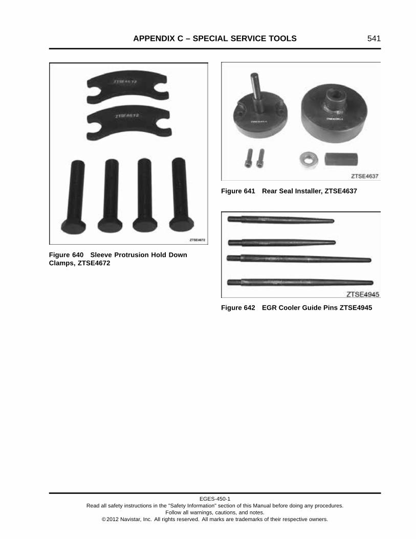
APPENDIX C – SPECIAL SERVICE TOOLS 541
Figure 640 Sleeve Protrusion Hold DownClamps, ZTSE4672
Figure 641 Rear Seal Installer, ZTSE4637
Figure 642 EGR Cooler Guide Pins ZTSE4945
EGES-450-1Read all safety instructions in the "Safety Information" section of this Manual before doing any procedures.
Follow all warnings, cautions, and notes.©2012 Navistar, Inc. All rights reserved. All marks are trademarks of their respective owners.

542 APPENDIX C – SPECIAL SERVICE TOOLS
EGES-450-1Read all safety instructions in the "Safety Information" section of this Manual before doing any procedures.
Follow all warnings, cautions, and notes.©2012 Navistar, Inc. All rights reserved. All marks are trademarks of their respective owners.

Printed in the United States of America