max. 600mm diameter grinding machine for quartz and
TRANSCRIPT

XG600
Max. 600mm diameter grinding machine for Quartz and Ceramic materials
Lynx

02 /
Product Overview
Basic Information
Structure
Cutting
Performance
Detailed
Information
Standard / Options
Applications
Diagrams
Specifications
Customer Support
Service
Ideal for grinding Quartz and Ceramic materials used in the manufacturing process of semiconductor wafers,
the latest model of the Lynx XG600 realizes a high level of precision and stable performance, while minimizing
the defect rate when grinding workpieces composed of pure metal with high thermal resistance properties.
Lynx XG600
Lynx XG600

03 02 /
Contents
02 Product Overview
Basic Information
04 Basic Structure05 Cutting Performance
Detailed Information
07 Standard / Optional
Specifications08 Applications09 Capacity Diagram10 Machine / NC Unit Specifications
11 Customer Support Service
1
3
5
67
2
4
➊ O.D. Groove Grinding
➋ O.D. End face Grinding
➌ Face Grinding
➍ I.D. Taper Grinding
➎ I.D. Curve Grinding
➏ I.D. Grinding
➐ I.D. Groove Grinding
Extended Machine Life and Easier Sludge (Quartz Dust) Treatment
The gap wiper and air-tight cover structure completely prevent the entry of Quartz or Ceramic dust into the machine slideway area, and improves long term durability.
The “straight” type coolant tank structure with no protruding interior parts makes cleaning easy.
Greater spatial efficiency due to adoption of a coolant tank that is removable both ways (forward and backward)
High Precision and Machine Structure Ideal for Grinding Works
Stable support structure for the X axis allows
higher grinding spindle load.
Top class level of precision allows grinding all
the way up to finishing operations..
Improved User Convenience and Options
Access for easy workpiece and tool change
achieved by creating a 650 mm space for door
opening and a spacious internal work zone.
Thanks to the addition of main spindle C axis,
holes and grooves on a pitch circle diameter
can also be included in the grinding process,
previously only possible on machining
centers.

04 /
Adoption of single body type, high rigidity bed structure enables minimal vibration and thermal error, while the LMG axis configuration provides smooth and precise feed movement.
Basic Structure Rapid traverse
X-axis 10 m/min (393.7 ipm)
Z-axis 20 m/min (787.4 ipm)
• 580mm of LMG rail spacing on the Z axis provides a high level of stability for the grinding head mounted on the X axis.
• Machine stability improved by adoption of single-body bed structure.
Feeding System
X-axis Box Guide
Z-axis Roller Type LM Guide
Machining Area
Ample space for workpiece and tool setting, with a maximum grinding diameter of 600mm and grinding length of 100mm
Chuck Size Machining Area
12 inch Ø600 X 100 mm ( Ø23.6 X 3.9 )
Max Ø
600 m
m
Max. grinding length
100 mm (3.9 inch)
Between Chuck and Grinding Spindle
400 mm (15.7 inch)
Single-body Bed StructureZ-axis
X-axis
Product Overview
Basic Information
Structure
Cutting
Performance
Detailed
Information
Standard / Options
Applications
Diagrams
Specifications
Customer Support
Service
580mm(22.8 inch)
(23. 6 inch)
Lynx XG600

05 04 /
14.1kW high output motor on the main spindle delivers high productivity for rough and finishing operations.
Spindle
Spindle nose
A2-8
Max. spindle speed
500 r/min
2500 r/min
Grinding spindle with a maximum rotating speed of 5000 r/min is fully optimized for cutting quartz and ceramic workpieces.* A different model of spindle is available
upon request (technical consultation
needed).
Grinding Spindle
Tool shank type
BT40 * Auto/Manual change types available
Max. spindle speed
5000 r/min

06 /
Dust Inflow and Coolant Leak Prevention
➊ The sliding cover protects the whole slant bed surface, and includes a 2 step wiper system to prevent inflow of grinding dust.
➋ The Multi-Cover protects the exposed part of the lower LM guide rail on the grinding spindle’s feeding axis (X axis).
➌ The air purge function supplies pressurized air from inside the spindle to prevent inflow of dust and coolant into the spindle bearings.
➊
➋
➌
Easy Tank Cleaning * Sludge treatment
➍ The straight type tank structure can be easily removed (forward/backward) from the bed.
➎ Sludge cleaning is much easier due to minimized protruding parts and steps on the coolant tank.
➎
➍
Product Overview
Basic Information
Structure
Cutting
Performance
Detailed
Information
Standard / Options
Applications
Diagrams
Specifications
Customer Support
Service
Lynx XG600

07 06 /
Standard / Optional Specifications
Diverse optional devices and features are available to meet specific customer requirements.
Standard Optional ◓Consultation Needed
NO. Description Specifications Lynx XG600
1Spindle
C axis functions (hole machining) ◦
2 Air Purge ◦
3Grinding Spindle
Doosan Standard ●
4 Customization ◦
5
Chuck
12” manual ●
6 12” hydraulic ◦
7 Vacuum chuck preparation (technical consultation required) ◦
8 No chuck available ◦
9Coolant pump
1 set of pump ●
10 2 sets of pump (Selectable Coolant Location function) ◦
11 Collector Mist Collector ◦
Productivity Improvement
Hole Machining (C-axis control)
➊➋
➌
➍
Selectable Coolant Location function
Independent coolant pumps are used for the separate OD and ID coolant supply nozzles. Each nozzle can be accurately set to provide optimum performance and minimized setting time.
Pump 1
Grinding of holes and grooves on the front face and OD of the workpiece can now be achieved thanks to the addition of a C axis function on the main spindle.
➊ Semicircular groove cutting ➋ ➌ Hole machining ➍ Keyway cutting
I.D. cutting O.D. cutting
Pump 2Coolant nozzle 2
I.D. cutting O.D. cutting
Coolant nozzle 1
Collector

08 /
Lynx XG600
Phased Command for Grinding Spindle and Display Functions
Command function (0-7 steps) allows easier and correct control of the grinding spindle speed, and can be checked in the “GRINDING RPM” section of the screen.
User-Friendly Operation Panel
During Tool Setting
During Grinding Machining Programming
S code commands available (rotating speed can be used as a command)
CNC optimized for DOOSAN's machine tools maximizes productivity.
DOOSAN FANUC i
• USB & PCMCIA card (standard)
• Counter, timer or special option button can be optionally installed
• Easy to add buttons when option specification is selected
• Control panel re-designed for more convenience
• LCD Size 10.4 inch standard
Spindle StepGrinding spindle speed
(r/min)M-code S-code GRINDING RPM
Step 0 50 Manual only - 0
Step 1 2000 M141 M103 S2000 1
Step 2 2500 M142 M103 S2500 2
Step 3 3000 M143 M103 S3000 3
Step 4 3500 M144 M103 S3500 4
Step 5 4000 M145 M103 S4000 5
Step 6 4500 M146 M103 S4500 6
Step 7 5000 M147 M103 S5000 7
* Step 0 : Set as default upon machine ON
Manual selection of grinding spindle
Allows visually check and control of the current rotating speed step by step
Manual operation of grinding tool clamp/unclamp
Product Overview
Basic Information
Structure
Cutting
Performance
Detailed
Information
Standard / Options
Applications
Diagrams
Specifications
Customer Support
Service

09 08 /
500 r/min 2500 r/min
External Dimensions
SPINDLE CENTER
1202 (47.3) 2220 (87.4)
2220 (87.4) 290(11.4) 2510 (98.8)
650(25.6) (DOOR OPEN)
670 (26.4) 730 (28.7) 138 (5.4) 880 (34.6) 870
(34.
3)
450
(17.
7)
1353
(53.
3)
429
(16.
9)
432
(17.
0)
432
(17.
0)
1364
(53.
7)
439
(17.
3)
635
(25.
0)
1120
(44.
1)
1105
(43.
5)
1757
(69.
2)
10 (0
.4) 10
(0.4
)
66 (2
.6)
Unit : mm (inch)Lynx XG600
Top view Front view
Spindle Power – Torque Diagram
Max. spindle speed
500 r/minMax. spindle speed
2500 r/min
Pow
er :
kW (H
p)
Torq
ue :
N·m
(ft-
lbs)
50010010
S1 Cont.
S3 15%S3 25%
S3 40%
6.3(8.4)
14.1(18.9)
269(198.5)218(160.9)
160(118.1)
120(88.6)
8.4(11.3) 11.4(15.3)
S1 Cont.
S3 15%S3 25%S3 40%
Spindle speed : r/min
Pow
er :
kW (H
p)
Torq
ue :
N·m
(ft-
lbs)
50010010
S1 Cont.
S3 15%S3 25%
S3 40%
6.3(8.4)
14.1(18.9)
269(198.5)218(160.9)
160(118.1)
120(88.6)
8.4(11.3) 11.4(15.3)
S1 Cont.
S3 15%S3 25%S3 40%
Spindle speed : r/min

10 /
Machine Specifications
Lynx XG600
NC Unit Specifications
Description Unit Lynx XG600
Capacity Max. grinding diameter mm (inch) 600 (23.6)
Max. grinding length mm (inch) 100 (3.9)
Chuck size inch 12
TravelsTravel distance
X-axis mm (inch) 400 (15.7)
Z-axis mm (inch) 320 (12.6)
Rapid traverseX-axis m/min (ipm) 10 (393.7)
Z-axis m/min (ipm) 20 (787.4)
Spindle Max. Spindle speed r/min 500 {2500}*
Spindle nose - A2-8
Max. spindle power (S3 15%/S3 40%/cont.) kW (Hp) 14.1/8.4/6.3
Grinding Spindle
No. of tool stations st 1
Max. Spindle speed r/min 5000
Tool shank type - BT40
Machine dimensions
Length x Width mm (inch) 2510 x 1803 (98.8 x 71.0)
Height mm (inch) 1757 (69.2)
Weight kg (lb) 2800 (6172.9)
Control CNC system - DOOSAN FANUC i
* Please contact DOOSAN to select detailed steady rest specifications.
FANUC
Standard Optional X N/A
NO. Division Item Spec DOOSAN-FANUC i
1
Controlled axis
Controlled axes X, Z
2 Simultaneously controlled axes 2 axes
3 Cs contouring control ◦
4 Synchronous / Composite control X5 Torque control ●
6 HRV2 control ●
7 Inch / metric conversion ●
8 Stored stroke check 1 ●
9 Stored stroke check 2,3 ●
10 Stored limit check before move ◦
11 Chamfering on / off ●
12 Unexpected disturbance torque detection function ●
13 Position switch ●
14
Operation
DNC operationIncluded in RS232C interface.
●
15 DNC operation with memory card ●
16 Quick program restart X17 Tool retract and recover ◦
18 Wrong operation prevention ●
19 Dry run ●
20 Single block ●
21 Reference position shift ●
22 Handle interruption ◦
23 Incremental feed x1, x10, x100 ●
24 Manual handle retrace ◦
25
Interpolation functions
Nano interpolation ●
26 Linear interpolation ●
27 Circular interpolation ●
28 Polar coordinate interpolation X
29 Cylindrical interpolation X30 Helical interpolation ◦*
31 Thread cutting, synchronous cutting ◦*
32 Multi threading ●
33 Thread cutting retract ●
34 Continuous threading ●
35 Variable lead thread cutting ●
36 Polygon machining with two spindles X
NO. Division Item Spec DOOSAN-FANUC i
37Interpolation functions
High-speed skip Input signal is 8 points. ◦
38 2nd reference position return G30 ●
39 3rd / 4th reference position return ●
40
Feed function
Override cancel ●
41 AI contour control I ◦
42 AI contour control II X43 Rapid traverse block overlap ●
44
Program input
Optional block skip 9 pieces ◦
45 Absolute / incremental programming
Combined use in the same block
●
46 Diameter / Radius programming ●
47 Automatic coordinate system setting ●
48 Workpiece coordinate system G52 - G59 ●
49 Workpiece coordinate system preset ●
50 Direct drawing dimension programming ●
51 G code system A ●
52 G code system B/C ●
53 Chamfering / Corner R ●
54 Custom macro ●
55 Addition of custom macro common variables
#100 - #199, #500 - #999 ●
56 Interruption type custom macro ●
57 Canned cycle ●
58 Multiple repetitive cycles ●
59 Multiple repetitive cycles II ●
60 Canned cycle for drilling ●
61 Coordinate system shift ●
62 Direct input of coordinate system shift ●
63 Pattern data input ●
64 Operation Guidance Function
EZ Guidei(Conversational Programming Solution) X
65 MANUAL GUIDE i ◦
66 Auxiliary/Spindle speed function
Constant surface speed control ●
67 Spindle override 0 - 150% ●
68 Spindle orientation ●* Available only with the Fanuc 0iTF_Type3.
Product Overview
Basic Information
Structure
Cutting
Performance
Detailed
Information
Standard / Options
Applications
Diagrams
Specifications
Customer Support
Service
Lynx XG600
11 10 /
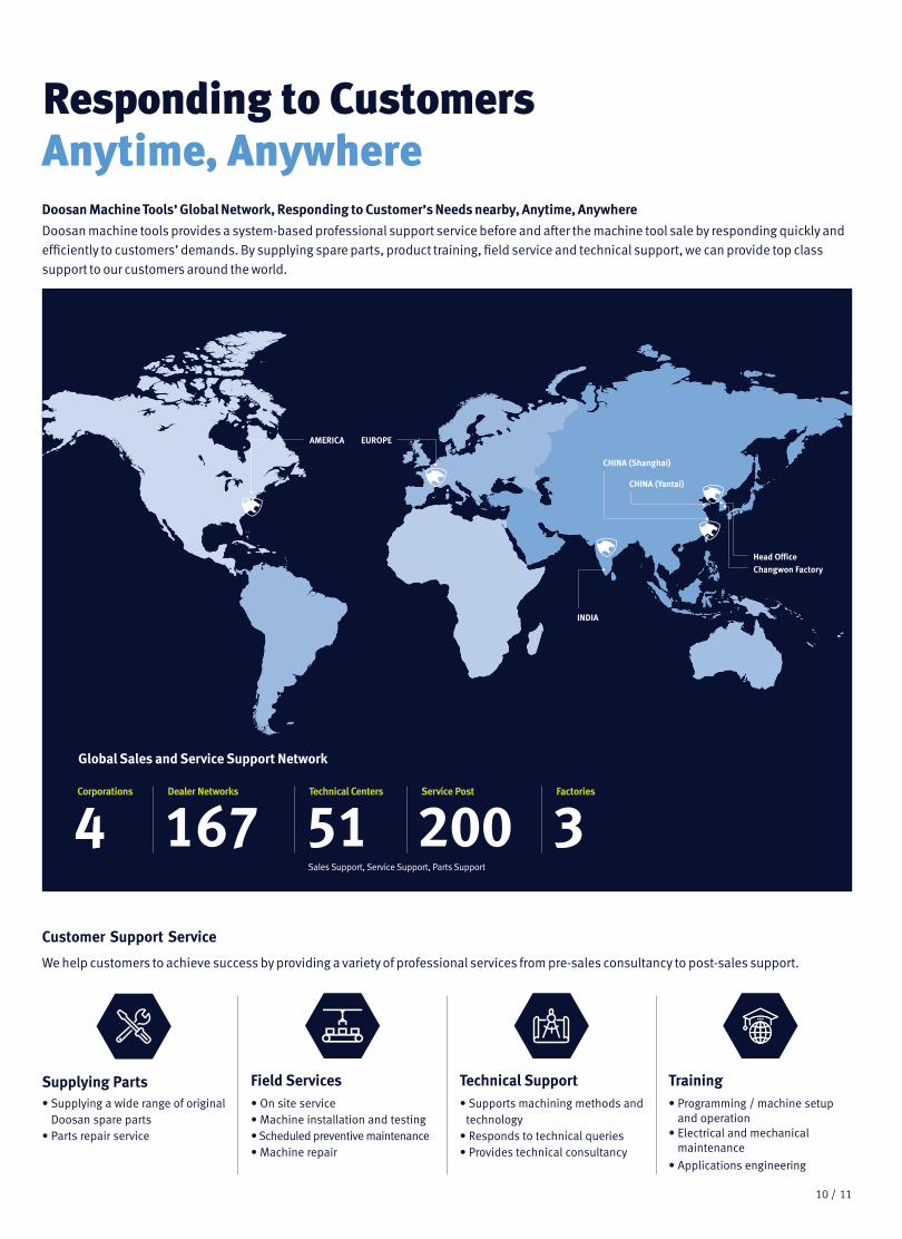
Doosan Machine Tools’ Global Network, Responding to Customer’s Needs nearby, Anytime, Anywhere
Doosan machine tools provides a system-based professional support service before and after the machine tool sale by responding quickly and efficiently to customers’ demands. By supplying spare parts, product training, field service and technical support, we can provide top class support to our customers around the world.
Responding to Customers Anytime, Anywhere
We help customers to achieve success by providing a variety of professional services from pre-sales consultancy to post-sales support.
Customer Support Service
Supplying Parts• Supplying a wide range of original
Doosan spare parts• Parts repair service
Field Services• On site service• Machine installation and testing• Scheduled preventive maintenance• Machine repair
Technical Support• Supports machining methods and
technology• Responds to technical queries• Provides technical consultancy
Training• Programming / machine setup
and operation• Electrical and mechanical
maintenance
• Applications engineering
Changwon FactoryHead Office
AMERICA EUROPE
CHINA (Yantai)
CHINA (Shanghai)
INDIA
4Global Sales and Service Support Network
Sales Support, Service Support, Parts Support
Corporations
200Service Post
51Technical Centers
167Dealer Networks
3Factories

ver. EN 210430 SU
* For more details, please contact Doosan Machine Tools.
*The specifications and information above-mentioned may be changed without prior notice.
* Doosan Machine Tools Co., Ltd. is a subsidiary of MBK Partners. The trademark is used under a licensing agreement with Doosan Corporation, the registered trademark holder.
There is a high risk or fire when using non-water-soluble cutting fluids, processing flammable materials, neglecting use coolants and modifying the machine without the consent of the manufacturer. Please check the SAFETY GUIDANCE carefully before using the machine.
Fire Safety Precautions
doosanmachinetools.com
Head Office22F T Tower, 30, Sowol-ro 2-gil Jung-gu, Seoul, Korea, 04637Tel +82-2-6972-0370/0350Fax +82-2-6972-0400
Doosan Machine Tools America19A Chapin Road, Pine Brook New Jersey 07058, United StatesTel: +1-973-618-2500 Fax: +1-973-618-2501
Doosan Machine Tools EuropeEmdener Strasse 24, D-41540 Dormagen, GermanyTel: +49-2133-5067-100 Fax: +49-2133-5067-111
Doosan Machine Tools IndiaNo.82, Jakkuar Village Yelahanka Hobil, Bangalore-560064Tel: + 91-80-2205-6900E-mail: [email protected]
Doosan Machine Tools ChinaRoom 101,201,301, Building 39 Xinzhuan Highway No.258 Songjiang District China Shanghai (201612)Tel: +86 21-5445-1155Fax: +86 21-6405-1472
Sales inquiry [email protected]