matrix - rs components · 2.3 personnel requirements 2.3.1 qualifications the following...
TRANSCRIPT

Matrix Linear Actuator
Read this manual before installing, operating
or maintaining this actuator. Failure to follow
safety precautions and instructions could
cause actuator failure and result in serious
injury, death or property damage.
Installation, operation and maintenance manual
1 General information . . . . . . . . . . . . . . . . . . . . . . . . . . . . . 5
1.1 Information on this manual . . . . . . . . . . . . . . . . . . . . . 5
1.2 Explanation of symbols . . . . . . . . . . . . . . . . . . . . . . . . 6
1.3 Limitation of liability . . . . . . . . . . . . . . . . . . . . . . . . . . . 6
1.4 Copyright . . . . . . . . . . . . . . . . . . . . . . . . . . . . . . . . . . . 7
1.5 Spare parts . . . . . . . . . . . . . . . . . . . . . . . . . . . . . . . . . 7
1.6 Warranty terms . . . . . . . . . . . . . . . . . . . . . . . . . . . . . . 7
1.7 Customer service . . . . . . . . . . . . . . . . . . . . . . . . . . . . . 7
2 Safety . . . . . . . . . . . . . . . . . . . . . . . . . . . . . . . . . . . . . . . . . 8
2.1 Use . . . . . . . . . . . . . . . . . . . . . . . . . . . . . . . . . . . . . . . 8
2.1.1 Intended use. . . . . . . . . . . . . . . . . . . . . . . . . . . . 8
2.1.2 Unintended and excluded use . . . . . . . . . . . . . . . 9
2.1.3 Essential performance . . . . . . . . . . . . . . . . . . . . 9
2.2 Responsibility of the owner and processor . . . . . . . . . . 8
2.3 Personnel requirements . . . . . . . . . . . . . . . . . . . . . . . 9
2.3.1 Qualifications . . . . . . . . . . . . . . . . . . . . . . . . . . . 9
2.4 Specific dangers . . . . . . . . . . . . . . . . . . . . . . . . . . . . . . 10
2.5 Safety equipment . . . . . . . . . . . . . . . . . . . . . . . . . . . . . 11
2.6 Safeguard against restart . . . . . . . . . . . . . . . . . . . . . . 13
2.7 Changes and to the device . . . . . . . . . . . . . . . . . . . . . . 13
2.7.1 Warning labels . . . . . . . . . . . . . . . . . . . . . . . . . . 15
2.7.2 Information labels . . . . . . . . . . . . . . . . . . . . . . . 15
2.8 Manufacturer’s declaration of EMC compliance . . . . . . 16
3 Technical data . . . . . . . . . . . . . . . . . . . . . . . . . . . . . . . . . . 24
3.1 Operating conditions . . . . . . . . . . . . . . . . . . . . . . . . . . 24
3.2 Product label . . . . . . . . . . . . . . . . . . . . . . . . . . . . . . . . 24
4 Structure and function . . . . . . . . . . . . . . . . . . . . . . . . . . . 25
4.1 Overview . . . . . . . . . . . . . . . . . . . . . . . . . . . . . . . . . . . 25
4.1.1 Matrix MAX1 and MAX3 . . . . . . . . . . . . . . . . . . 25
4.1.2 Matrix MAX6 . . . . . . . . . . . . . . . . . . . . . . . . . . . 25
4.2 Brief description . . . . . . . . . . . . . . . . . . . . . . . . . . . . . 26
4.3 Special features . . . . . . . . . . . . . . . . . . . . . . . . . . . . . . 27
4.4 Construction group description . . . . . . . . . . . . . . . . . . 28
4.5 Requirement for 3rd party power supply . . . . . . . . . . . 28
4.6 Connections . . . . . . . . . . . . . . . . . . . . . . . . . . . . . . . . . 29
4.7 Operating elements . . . . . . . . . . . . . . . . . . . . . . . . . . . 30
4.8 Options . . . . . . . . . . . . . . . . . . . . . . . . . . . . . . . . . . . . 31
4.8.1 Emergency lowering device . . . . . . . . . . . . . . . . 31
4.8.2 Quick adjustment . . . . . . . . . . . . . . . . . . . . . . . . 31
4.8.3 Electrical pinch protection . . . . . . . . . . . . . . . . . 32
4.8.4 Life span display . . . . . . . . . . . . . . . . . . . . . . . . 33
4.8.5 Mechanical pinch protection . . . . . . . . . . . . . . . 33
4.8.6 Master slave actuator function . . . . . . . . . . . . . . 33
4.8.7 Impulse transmitter . . . . . . . . . . . . . . . . . . . . . . 33
4.9 Accessories . . . . . . . . . . . . . . . . . . . . . . . . . . . . . . . . . 34
Contents
5 Transport, packaging and storage . . . . . . . . . . . . . . . . . . . 35
5.1 Safety information for the transport . . . . . . . . . . . . . . . 35
5.2 Transport inspection . . . . . . . . . . . . . . . . . . . . . . . . . . 35
5.3 Return to the manufacturer . . . . . . . . . . . . . . . . . . . . . 36
5.4 Packaging . . . . . . . . . . . . . . . . . . . . . . . . . . . . . . . . . . 36
5.5 Storage . . . . . . . . . . . . . . . . . . . . . . . . . . . . . . . . . . . . 37
6 Installation and first operation . . . . . . . . . . . . . . . . . . . . . 38
6.1 Installation location . . . . . . . . . . . . . . . . . . . . . . . . . . . 39
6.2 Inspections prior to first operation . . . . . . . . . . . . . . . . 39
6.3 Installation . . . . . . . . . . . . . . . . . . . . . . . . . . . . . . . . . . 41
6.4 Connection to the control Unit . . . . . . . . . . . . . . . . . . . 44
6.5 Connection to operating element . . . . . . . . . . . . . . . . . 47
6.5.1 Connect MAX1 and MAX3 to operating element 47
6.5.2 Connect MAX6 to operating element . . . . . . . . . 47
6.6 Connect to power supply . . . . . . . . . . . . . . . . . . . . . . . 51
6.6.1 Connect MAX1 and MAX3 to power supply . . . . 51
6.6.2 Connect MAX6 to energy supply . . . . . . . . . . . . 51
6.7 Requirements concerning the installation of the
actuators with options . . . . . . . . . . . . . . . . . . . . . . . . . 54
6.7.1 Emergency lowering device . . . . . . . . . . . . . . . . 54
6.7.2 Quick adjustment . . . . . . . . . . . . . . . . . . . . . . . . 55
6.7.3 Electrical pinch protection . . . . . . . . . . . . . . . . . 55
6.7.4 Mechanical pinch protection . . . . . . . . . . . . . . . 56
6.7.5 Master-slave actuator function . . . . . . . . . . . . . 56
7 Operation . . . . . . . . . . . . . . . . . . . . . . . . . . . . . . . . . . . . . . 59
7.1 Safety . . . . . . . . . . . . . . . . . . . . . . . . . . . . . . . . . . . . . 59
7.2 Turn on . . . . . . . . . . . . . . . . . . . . . . . . . . . . . . . . . . . . 60
7.3 Turn off . . . . . . . . . . . . . . . . . . . . . . . . . . . . . . . . . . . . 60
7.4 Action before Use . . . . . . . . . . . . . . . . . . . . . . . . . . . . . 61
7.5 Action during the operation . . . . . . . . . . . . . . . . . . . . . 62
7.5.1 Normal operation . . . . . . . . . . . . . . . . . . . . . . . 62
7.5.2 Operate emergency lowering device . . . . . . . . . 62
7.5.3 Operate quick adjustment . . . . . . . . . . . . . . . . . 64
7.6 Disengagement in case of emergency . . . . . . . . . . . . . 67
7.6.1 Shut down MAX1 and MAX3 . . . . . . . . . . . . . . . 68
7.6.2 Shut down MAX6 . . . . . . . . . . . . . . . . . . . . . . . . 69
7.7 Action after use . . . . . . . . . . . . . . . . . . . . . . . . . . . . . . 69
2

8 Maintenance . . . . . . . . . . . . . . . . . . . . . . . . . . . . . . . . . . . 70
8.1 Maintenance plan . . . . . . . . . . . . . . . . . . . . . . . . . . . . 71
8.2 Maintenance work . . . . . . . . . . . . . . . . . . . . . . . . . . . . 72
8.2.1 Cleaning . . . . . . . . . . . . . . . . . . . . . . . . . . . . . . 72
8.2.2 Inspections and readings . . . . . . . . . . . . . . . . . . 72
8.2.3 Check Sealing function of plug . . . . . . . . . . . . . . 73
8.2.4 Check of visual condition . . . . . . . . . . . . . . . . . . 75
8.2.5 Check options . . . . . . . . . . . . . . . . . . . . . . . . . . 76
8.3 Measures after completed maintenance . . . . . . . . . . . 76
9 Malfunctions . . . . . . . . . . . . . . . . . . . . . . . . . . . . . . . . . . . 77
9.1 Malfunction table . . . . . . . . . . . . . . . . . . . . . . . . . . . . . 79
9.1.1 Matrix MAX1 and MAX3 . . . . . . . . . . . . . . . . . . 79
9.1.2 Matrix MAX6 . . . . . . . . . . . . . . . . . . . . . . . . . . . 80
9.2 Start of operation after fixed malfunction . . . . . . . . . . . 81
10 Dismantling . . . . . . . . . . . . . . . . . . . . . . . . . . . . . . . . . . . 82
10.1 Dismantling . . . . . . . . . . . . . . . . . . . . . . . . . . . . . . . . . 83
10.1.1 Dismantling of MAX1 and MAX3 . . . . . . . . . . . 83
10.1.2 Dismantle MAX6 . . . . . . . . . . . . . . . . . . . . . . . 83
10.2 Disposal . . . . . . . . . . . . . . . . . . . . . . . . . . . . . . . . . . . 86
3

4
1.1 Information on this manual
This manual provides important information on how to work with
the actuator (also called device) safely and efficiently.
The Manual is part of the device, must always be kept in the
device’s direct proximity and should be available for the personnel
at any time. All personnel working with the device must read and
understand this Manual before starting any work. Strict compliance
with all specified safety notes and instructions is a basic requirement
for safety at work.
Moreover, the accident prevention guidelines and general safety
regulations applicable at the place of use of the device must also
be complied with.
For better representation of circumstances, the illustrations used
are not necessarily to scale and may vary from the actual design of
the device.
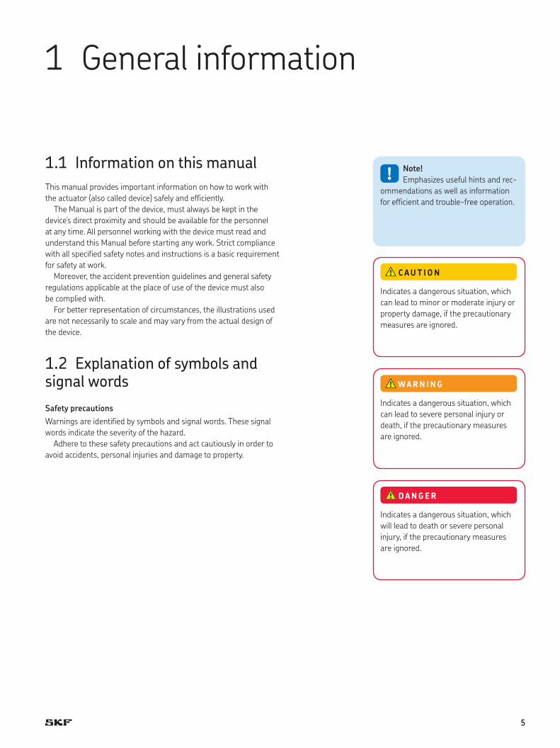
1.2 Explanation of symbols and signal words
Safety precautions
Warnings are identified by symbols and signal words. These signal
words indicate the severity of the hazard.
Adhere to these safety precautions and act cautiously in order to
avoid accidents, personal injuries and damage to property.
1 General information
!Note!
Emphasizes useful hints and rec-
ommendations as well as information
for efficient and trouble-free operation.
Indicates a dangerous situation, which
can lead to severe personal injury or
death, if the precautionary measures
are ignored.
WARN ING
Indicates a dangerous situation, which
can lead to minor or moderate injury or
property damage, if the precautionary
measures are ignored.
C AUT ION
Indicates a dangerous situation, which
will lead to death or severe personal
injury, if the precautionary measures
are ignored.
DANGER
5

1.3 Limitation of liability
All information and notes in this manual were compiled under due
consideration of valid standards and regulations, the present status
of technology and our years of knowledge and experience.
The manufacturer will not be liable for damage resulting from:
• disregarding this manual
• unintended use
• employment of untrained personnel
• unauthorized conversions
• technical modifications
• manipulation or removal of the screws on the device
• use of unapproved spare parts
In case the actuator is customised, the actual product delivered may
be different from what is described in the manual. In this case, ask
SKF for any additional instructions or safety precautions relevant to
these actuators.
We reserve the right to make technical modifications to the actua-
tor to improve usability.
1.4 Copyright
This Manual is protected by copyright law and exclusively to be
used for internal purposes.
Passing this Manual on to third parties, duplication of any kind
– even in form of excerpts – as well as the use and/or disclosure of
the contents without the written consent of the manufacturer is not
permitted, except for internal purposes.
Violations oblige to compensation. The right for further claims
remains reserved.
6

1.5 Spare parts
The Matrix linear actuator is not designed for repair work. All war-
ranty and service claims become void without notice if any screws
on the linear actuator have been manipulated.
The device must be dismantled and sent to the manufacturer. The
address is listed on the cover back.
1.6 Warranty terms
The applicable and effective warranty terms are those contained in
the manufacturer’s terms and conditions of sale.
1.7 Customer service
SKF Customer Service is always available to provide technical
information and answer questions.
The contact information for SKF Customer Service can be found
on www.skf.com.
Safety hazard caused by wrong spare parts
Wrong or faulty spare parts can adversely affect
safety and cause damage, malfunctions or total
failure.
Therefore:
• Use only genuine spare parts from the manufacturer.
• Spare parts in/on the device may only be replaced by the
manufacturer.
WARN ING
7

2 Safety
This paragraph provides an overview of all important safety aspects
for optimal protection of personnel as well as safe and trouble-free
operation.
Disregarding this Manual and safety regulations specified therein
may result in considerable danger and possible serious injury or
death.
2.1 Use2.1.1 Intended useThe device has been designed and built exclusively for its intended
purpose as described in these instructions.
The device is only used for the dynamic centric compression
or tensile-loaded lift. It is only intended for interior use and is
implemented in medical devices as well as in industrial and
construction technology.
range of environmental conditions:
• Ambient temperature: 0 °C to + 40 °C
• Relative humidity : 5% to 85%
• atmospheric pressure: 700 hPa to 1060 hPa
2.1.1.1 Product life time
the linear actuators MAX are designed for a service life of 10 years
or 10 000 double strokes at a stroke length of 200 mm.
Risk from misuse
Any utilization of this device beyond its intended purpose may
lead to potentially hazardous situations.
Therefore:
• Strictly adhere to all safety precautions and instructions in this
operating manual.
• Do not make this device subject to weather conditions, strong
UV rays, corrosive or explosive air media as well as other
aggressive media.
• Do not modify, retool or change the structural design or
individual components of the actuator.
• Never use the device outside of the technical application and
operational limits.
WARN ING
8

2.1.2 Unintended useAny use other that the intended use, or modifications to the device
without the manufacturer’s written agreement, or operation beyond
the technical limits, is considered unauthorized.
Specific application exemptions are:
• Flammable anaesthetic mixture with air
• Flammable anaesthetic mixture with oxygen or nitrous oxide
• Increased radiation
2.1.3 Essential performancethe essential performance of the linear actuator MAX is moving or
holding a load within the boundaries defined by the device specifica-
tions given in this operating manual and the datasheet.
Any injury, damage or loss caused by violation of these instructions
will be the responsibility of the customer.
2.2 Responsibility of the owner and processorThe device is designed for personal use and is also used in
commercial applications by owner or processors.
The processor is the contracting partner of the reseller or the manufacturer. The processor installs the device in a complete system
(application).
The owner or processor of the system is therefore subject to the requirements of the Occupational Health and Safety Act.
In addition to the safety instructions in this Manual, the owner or processor must do the following concerning these safety and acci-
dent prevention guidelines and environmental protection regula-
tions, applicable to the site of the system’s installation:
• Inform themselves of applicable industrial safety regulations and
determine additional hazards that arise due to the specific work-
ing conditions prevailing at the site where the device is installed
using risk assessment. The risk assessment must be implemented
in the form of work instructions for device operation.
• Must confirm that the work instructions created for the system
including the device satisfy current legal requirements and must
alter the instructions if they don’t.
• Clearly regulate and specify the responsibilities for installation,
operation, maintenance, and cleaning.
• Ensure that all employees who deal with the device have read and
understood this Manual.
• Provide personnel with the required protective equipment.
• In addition, owner must train personnel at regular intervals and
inform personnel of the hazards.
!Note!
Any unauthorized use of the device can cause personal
injury and property damage. Always adhere to the instructions
given in this manual.
9

In addition, owner or processors must ensure that the device is in
adequate working condition. They must do the following:
• Ensure that the maintenance intervals described in these instruc-
tions are complied with.
• Have all safety devices inspected regularly for function and
completeness.
2.3 Personnel requirements
2.3.1 QualificationsThe following qualifications are specified for different areas of
activity listed in the manual.
• An instructed person (Operator)
has been instructed by the customer in an orientation session on
the assigned tasks and possible dangers in case of improper
behaviour.
• Qualified personnel
based on their professional training, know-how and experience as
well as knowledge of the applicable standards and regulations is
able to perform assigned work activities and to detect and avoid
possible dangers on their own.
• A professional electrician
based on his/her professional training, know-how and experience
as well as knowledge of the applicable standards and regulations
is able to perform work on electrical systems and to detect and
avoid possible dangers on his/her own.
The professional electrician has been trained for the special
location where he/she works and knows the relevant standards
and regulations.
Only persons who are expected to perform their tasks reliably are
permitted as personnel. Persons whose reaction capability is
impaired, e.g. through drugs, alcohol or medication, are not
permitted.
Improper installation, operation and maintenance can result
in serious injury, death or property damage.
Use only qualified, instructed, or trained personnel (as described
below) who have read, understand and follow these instructions.
WARN ING
10

2.4 Specific dangersThe following section lists the residual risks that have been deter-
mined by the risk assessment.
• Heed the safety instructions listed here, and the warnings in
subsequent chapters of this Manual, to reduce health hazards
and to avoid dangerous situations.
Danger to life caused by electric current
Touching conductive parts causes a direct danger to life.
Damage to insulation or individual components can cause dan-
ger to life.
Therefore:
• In the event of damage to insulation, switch off the power
supply immediately and have the defective parts repaired.
• Work on the electrical system must be carried out only by
skilled electricians.
• De-energize the machine for all work on the electrical system.
• Before maintenance, cleaning or repair work, switch off the
power supply and perform lockout procedures so it cannot be
turned on again.
• Do not bridge fuses or make them ineffective. When changing
fuses, make sure you use the correct amperage.
• Keep moisture away from conductive parts. If you do not, this
can cause short circuit.
DANGER
Electric current
Electric shock hazard
Ensure that cables cannot become pinched or damaged. Check
that the mains voltage corresponds to nominal values on the
product label. Ensure that the cabling is correctly installed in
the cable channel.
Beware of damage to actuator caused by splashing or
hose-directed water. The actuators are in accordance with IP66.
Exposure to risk of damage must be prevented at all times.
WARN ING
Electric shock hazard
The linear actuator MAX do not have any on/off-switch and if
required to be switched off, for example in a emergency, the
actuator must be disconnected from the control unit or the
power supply. Only this measure will de-energize the actuator.
Applications where the actuators are built in, must provide an
emergency stop switch or isolation from the mains supply on all
conductors.
WARN ING
11

Crush hazard
Do not let any object or person come in contact with the push
and / or protection tube on front and rear attachment.
Risk of damage to the linear actuator caused by static and
dynamic overloading of the actuator. Do not use the actuator
beyond the permissible operating data
WARN ING
Pinch hazard
When the actuator runs into fixed objects, the driving force can
cause personal injury. If the actuator is left unattended, check
that the full stroke length is free of obstacles and that there is
nobody in the stroke area. Alternatively, provide a means of
disconnecting all conductors from the mains power supply.
WARN ING
Injury due to cracks and related openings in the housing
of the actuator and / or its accessories:
If the housing is damaged due to stock, beakage or heavy wear,
cease using the device and follow the dismantling instructions.
WARN ING
Any side-acting forces can destroy the actuator and pose a risk
of serious injury. During the stroke, do not manipulate any of the
elements connected to the actuator.
WARN ING
Danger of injury caused by moving components
Rotating and/or linearly moving components can cause severe
injury.
Therefore:
• Do not work on or place any of your body, hands, or arms near
moving components
WARN INGMoving components
12

Overload safety cut-off
Thermal fuse protection
Overload protection (optional)
2.5 Safety equipment
Integration in an emergency-stop system required
(for certain applications)
The device is only intended for installation into an an application or
system. It does not have its own operating control elements and
does not have an independent emergency-stop-function.
Install the device so that it is part of an emergency shut-off
system and can be stopped if necessary.
The emergency shut-off system has to be connected in such a
way that a disruption of the power supply or the reactivation of the
power supply after a power disruption cannot cause a hazardous
situation for persons and objects.
The emergency shut-off systems must always be freely
accessible.
!Note!
The processor decides which applications require the
installation of an emergency shut-off system.
The following safety installations may have been installed:
Matrix MAX1/Matrix MAX3
In its standard version the device does not feature an overload safety
shut-off and must be turned off via an SKF control unit. MAX11 and
MAX31 are exceptions.
Matrix MAX6
The control unit with integrated power shut-off has been installed in
the motor housing.
Matrix MAX1/Matrix MAX3
In its standard version the device does not feature a thermal fuse
protection and can be destroyed through overheating. An SKF
control unit with integrated thermal switch turns the device off in
emergencies.
Danger due to malfunctioning safety equipment
For safe operation, be sure all safety equipment is in good
working order.
Therefore:
• Always check functionality of safety equipment according to
the maintenance plan.
• Never disengage safety equipment.
• Safety equipment may never be by-passed or modified.
WARN ING
13
Matrix MAX6
A thermal fuse protection has been integrated in the motor housing.
A ball screw nut converts the rotation of the gear unit into a linear
motion. If an overload occurs when the actuator is operating, a ball
detent clutch will operate, thus stopping linear motion.
Information concerning emergency lowering function, quick adjust-
ment, electrical pinch protection and mechanical pinch protection
can be found in the chapter “Structure and Function”.
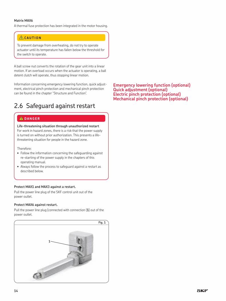
2.6 Safeguard against restart
Protect MAX1 and MAX3 against a restart.
Pull the power line plug of the SKF control unit out of the
power outlet.
Protect MAX6 against restart.
Pull the power line plug (connected with connection (1) out of the
power outlet.
To prevent damage from overheating, do not try to operate
actuator until its temperature has fallen below the threshold for
the switch to operate.
C AUT ION
Life-threatening situation through unauthorized restart
For work in hazard zones, there is a risk that the power supply
is turned on without prior authorization. This presents a life-
threatening situation for people in the hazard zone.
Therefore:
• Follow the information concerning the safeguarding against
re-starting of the power supply in the chapters of this
operating manual.
• Always follow the process to safeguard against a restart as
described below.
DANGER
Fig. 1
1
Emergency lowering function (optional)Quick adjustment (optional)Electric pinch protection (optional)Mechanical pinch protection (optional)
14

2.7 Modifications on the device
To avoid hazardous situations and to ensure optimal performance,
do not make any changes or modifications to the device unless they
have been specifically authorized by SKF.
2.7.1 Warning labelsThe following symbols and information decals can be found in the
danger zone. They refer to the immediate vicinity around their
location.
Do not hold on to the device.
(part number 0120698)
The label will be attached for specific applications, e.g. for patient
lifters.
Do not hold on to the actuator or casing tube.
Do not put body parts and objects inbetween moving parts.
Keep body parts or objects away from moving parts.
Adhere to operation instructions and warnings.
Fig. 2
Danger of injury because of illegible symbols
Over the course of time stickers and decals may become dirty or
illegible for some other reason.
Therefore:
• Keep any safety, warning and operation related decals in
legible condition at all times.
• Replace damaged decals or stickers immediately.
WARN ING
15
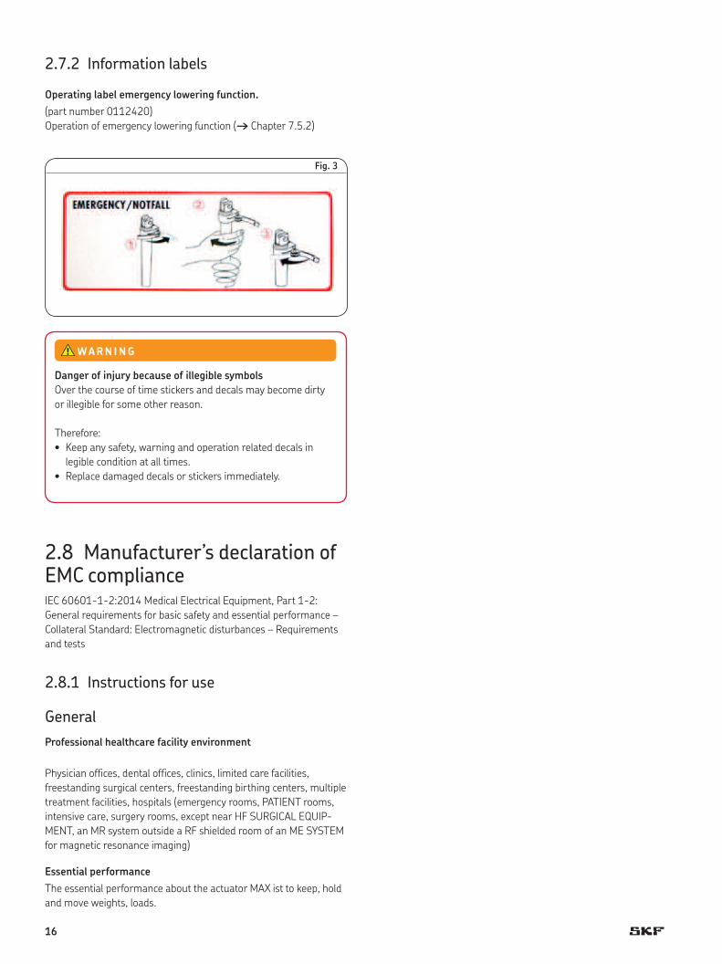
2.7.2 Information labels
Operating label emergency lowering function.
(part number 0112420)
Operation of emergency lowering function († Chapter 7.5.2)
Fig. 3
2.8 Manufacturer’s declaration of EMC complianceIEC 60601-1-2:2014 Medical Electrical Equipment, Part 1-2:
General requirements for basic safety and essential performance –
Collateral Standard: Electromagnetic disturbances – Requirements
and tests
2.8.1 Instructions for use
General
Professional healthcare facility environment
Physician offices, dental offices, clinics, limited care facilities,
freestanding surgical centers, freestanding birthing centers, multiple
treatment facilities, hospitals (emergency rooms, PATIENT rooms,
intensive care, surgery rooms, except near HF SURGICAL EQUIP-
MENT, an MR system outside a RF shielded room of an ME SYSTEM
for magnetic resonance imaging)
Essential performance
The essential performance about the actuator MAX ist to keep, hold
and move weights, loads.
Danger of injury because of illegible symbols
Over the course of time stickers and decals may become dirty
or illegible for some other reason.
Therefore:
• Keep any safety, warning and operation related decals in
legible condition at all times.
• Replace damaged decals or stickers immediately.
WARN ING
16
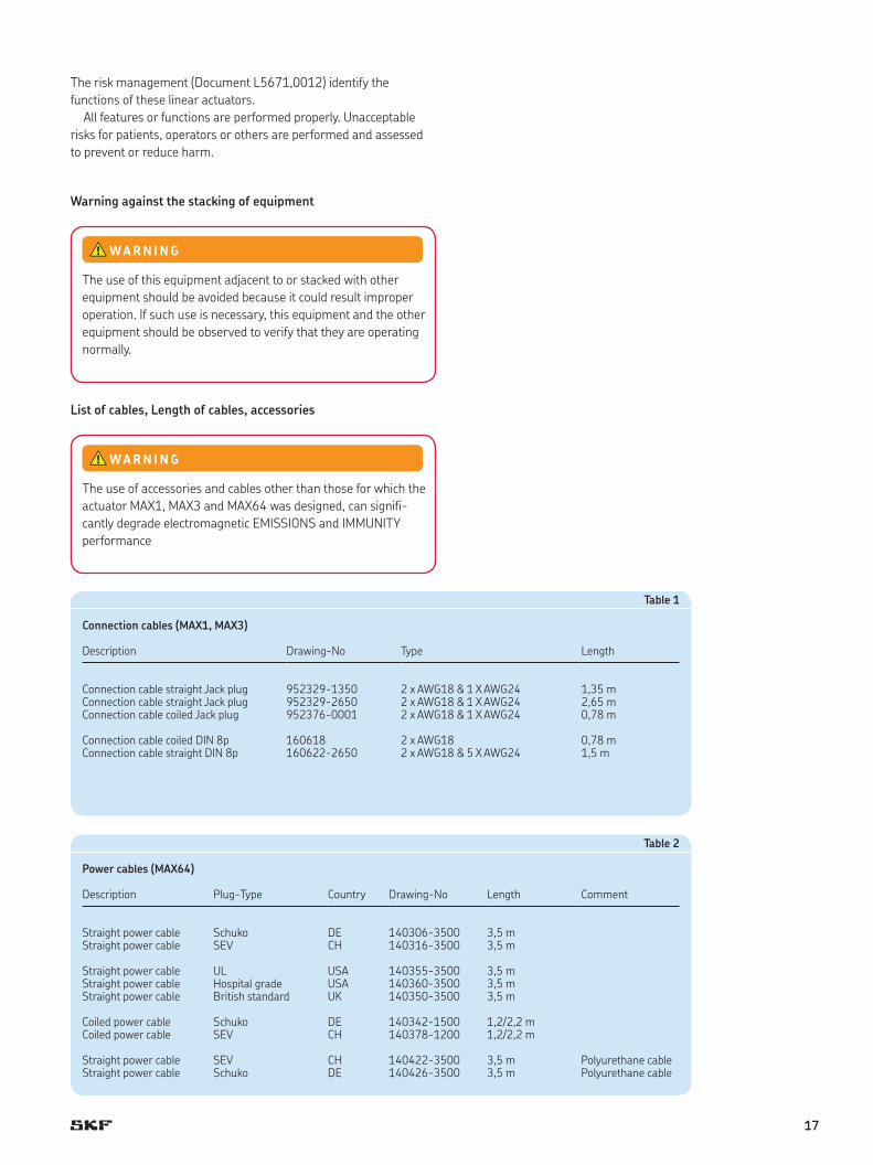
The risk management (Document L5671,0012) identify the
functions of these linear actuators.
All features or functions are performed properly. Unacceptable
risks for patients, operators or others are performed and assessed
to prevent or reduce harm.
Warning against the stacking of equipment
List of cables, Length of cables, accessories
The use of this equipment adjacent to or stacked with other
equipment should be avoided because it could result improper
operation. If such use is necessary, this equipment and the other
equipment should be observed to verify that they are operating
normally.
WARN ING
The use of accessories and cables other than those for which the
actuator MAX1, MAX3 and MAX64 was designed, can signifi-
cantly degrade electromagnetic EMISSIONS and IMMUNITY
performance
WARN ING
Table 2
Power cables (MAX64)
Description Plug-Type Country Drawing-No Length Comment
Straight power cable Schuko DE 140306-3500 3,5 mStraight power cable SEV CH 140316-3500 3,5 m
Straight power cable UL USA 140355-3500 3,5 mStraight power cable Hospital grade USA 140360-3500 3,5 mStraight power cable British standard UK 140350-3500 3,5 m
Coiled power cable Schuko DE 140342-1500 1,2/2,2 mCoiled power cable SEV CH 140378-1200 1,2/2,2 m
Straight power cable SEV CH 140422-3500 3,5 m Polyurethane cableStraight power cable Schuko DE 140426-3500 3,5 m Polyurethane cable
Table 1
Connection cables (MAX1, MAX3)
Description Drawing-No Type Length
Connection cable straight Jack plug 952329-1350 2 x AWG18 & 1 X AWG24 1,35 mConnection cable straight Jack plug 952329-2650 2 x AWG18 & 1 X AWG24 2,65 mConnection cable coiled Jack plug 952376-0001 2 x AWG18 & 1 X AWG24 0,78 m
Connection cable coiled DIN 8p 160618 2 x AWG18 0,78 mConnection cable straight DIN 8p 160622-2650 2 x AWG18 & 5 X AWG24 1,5 m
17

RF communications equipment
Technical description
Requirements applicable to all ME equipment and ME Systems
a) Compliance for each Emissions and Immunity standards
Emission guidance
The Linear actuator MAX1, MAX3 and MAX64 is intended for use
in the electromagnetic environment specified below.
The customer or user of the actuator should ensure that they
are used in such an environment.
Table 3
Emission tests Compliance Electromagnetic environment- guidance
Radiated electromagnetic field emissions CISPR 14 (EN 55014)
Group 1
Radiated electromagnetic field emissions CISPR 14 (EN 55014)
Class B ME equipment class B
b) Deviations from Standards and allowances used (MAX1 and
MAX3 only) see table 4, page 19.
c) Instruction for maintaining BASIC Safety and Essential perfor-
mance for the expected Service life
One time approved in the final application not change is allowed
due to the EMC influence.
Portable RF communications equipment (including peripherals
such as antenna cables and external antennas) should be used
no closer than 30cm to any part of the ME equipment. Other-
wise, degradation of the performance of this equipment could
result
WARN ING
! Note!
Do not change the once installed final application due to
EMC view
This product was tested against actual conditions of frequency
wireless environment present in Europe
WARN ING
18

Table 5
Enclosure port
Phenomenon Basic EMC standard or testmethod
Immunity test levelsProfessional healtcare Home healthcare
facility environment environment
Electrostatic discharge IEC 61000-4-2 ±8 kV contact ±2 kV, ±4 kV, ±8 kV, ±15 kV air
±8 kV contact ±2 kV, ±4 kV, ±8 kV, ±15 kV air
Radiated RF EM fieldsa) IEC 61000-4-3 3 V/mf) 10 V/mf)
80 MHz – 2,7 GHzb) 80 MHz – 2,7 GHzb)
80% AM at 1 kHzc) 80% AM at 1 kHzc)
Proximity fields from RF wireless communication equipments
IEC 61000-4-3 (→ table 10 on page 23) (→ table 10 on page 23)
Rated power frequency magnetic fieldsd), e)
IEC 61000-4-8 30 A/mg)
50 Hz or 60 Hz30 A/mg)
50 Hz or 60 Hz
a) The interface between the patient physiological signat simulation, if used, and the ME equipment or ME system shall be located within 0,1 m of the vertical plane of uniform field area in one orientation of the ME equipment or ME system
b) ME equipment and ME system that intentionally receive RF electromagnetic energy for the purpose of their operation shall be tested at the frequency of reception. Testing may be performed at other modulation frequencies identified by the risk management process. This test assesses the basic safety and essential performance of an intentional receiver when an ambient signal is in the passband. It is understood that the receiver might not achieve normal reception during the test.
c) Testing may be performed at other modulation frequencies identified by the risk management process.d) Applies only to ME equipment an ME systems with magnetically sensitive components or circuitry.e) During the test, the ME equipment or ME system may be powered at any nominal input voltage, but with the same frequency as the test signal († IEC60601-1-2:2014 / table 1)f) Before modulation is appliedg) This test level assumes a minimum distance between the ME equipment or the ME system and sources of power frequency magnetic field of at least 15 cm. If the RISK ANALYSIS shows that the
ME equipment or ME system will be used closer than 15 cm to sources of power frequency magnetic field, the immunity test level shall be adjusted as appropriate for the minimum expected distance.
Table 4
Deviations from Standard 5.2.2.1b)
Test type Value Sample Remark
60601-1-2:2014 9.1 Interference voltage emissionrequirement 0 dB QP marginmeasurement –1,8 dB / 154 kHz MAX 30 FAIL
–0,9 dB /172 kHz MAX 30 FAIL
9.2 Discontinous disturbance (clicks) emission high click rate MAX 11, MAX 30 FAIL (both actuator types)PASS with Control unit KOM
10.4 Surges immissionrequirement L-L (AC) ±1 kV, ± 2 kV MAX 11, MAX 30 N/A (only product for 24 VDC)requirement L-PE (AC) ±1 kV, ± 2 kV MAX 11, MAX 30 N/A (only product for 24 VDC)requirement L-L (DC) ±0,5 kVrequirement L-PE (DC) ±0,5 kVmeasurement ±0,5 kV MAX 11, MAX 30 PASS with DC power
61000-6-3 9.2 Discontinous disturbance (clicks) emission high click rate MAX 11, MAX 30 FAIL (both actuator types)PASS with Control unit KOM
Action plan according the deviations:In the applications the MAX1 and MAX3 are operated with a Control unit supplied by mains. Therefore we accept the deviations.The end user must secure compliance to the applicable EMC requirements.
Immunity Test levels (IEC 60601-1-2:2014)
19

Table 6
Input a.c. power port
Phenomenon Basic EMC standard
Immunity test levels Immunity test levelsProfessional healtcare Home healthcare
facility environment environment
Electrical fast transients / burstsa), l), o)
IEC 61000-4-4 ±2 kV ±2 kV
Surgesa), b), j), o)
Line-to-lineIEC 61000-4-5 ±0,5 kV, ±1 kV ±0,5 kV, ±1 kV
Surgesa), b), j), k), o)
Line-to-groundIEC 61000-4-5 ±0,5 kV, ±1 kV, ±2 kV ±0,5 kV, ±1 kV, ±2 kV
Conducted disturbancesinduced by RF fieldc), d), o)
IEC 61000-4-6 3 Vm) 3 Vm)
0,15 MHz – 80 MHz 0,15 MHz – 80 MHz
6 Vm) in ISM bands between 0,15 MHz and 80 MHzn)
6 Vm) in ISM and amateur radio bands between 0,15 MHz and 80 MHzn)
80% AM at 1 kHze) 80% AM at 1 kHze)
Voltage dipsf), p), r) IEC 61000-4-11 0% UT; 0,5 cycleg)
At 0°, 45°, 90°, 135°, 180°, 225°, 270° and 315° q)
0% UT; 0,5 cycleg)
At 0°, 45°, 90°, 135°, 180°, 225°, 270° and 315° q)
0% UT; 1 cycle and 70% UT; 25/30 cyclesh) 0% UT; 1 cycle and 70% UT; 25/30 cyclesh)
Single phase: at 0° Single phase: at 0°
Voltage interruptionf), i), o), r) IEC 61000-4-11 0% UT; 250/300 cycleh) 0% UT; 250/300 cycleh)
a) The test may be performed at any one power input voiltage within the ME equipment or ME system rated voltage range. If the ME equipment or ME system is tested at one power input voltage, it is not necessery to re-test at additional voltages.
b) All ME equipment and ME system cables are attached during the test.c) Calibration for current injection clamps shall be performed in a 150 Ω system.d) If the frequency stepping skips over an ISM amateur band, as applicable, an additional test frequency shall be used in the IMS or amateur radio band. This applies to each ISM and radio band
within the specified frequency range.e) Testing may be performed at other modulation frequencies identified by the risk management process.f) ME equipment and ME system with a d.c. power input intended for use with a.c.-to-d.c. converters shall be tested using a converter that meets the specification of the manufacturer of the
ME equipment or ME system. The immunity test levels are applied to the a.c. power input of the converter.g) Applicable only to ME equipment and ME systems connected to single-phase a.c. mains.h) E.g. 10/12 means 10 periods at 50 Hz or 12 periods at 60 Hz.i) ME equipment and ME systems with rated input current greater than 16 A/phase shall be interrupted once for 250/300 cycles at any angle and at all phases at the same time ( if applicable).
ME equipment and ME systems with battery backup shall resume line power operation after the test. or ME equipment and ME systems with rated input current not exceeding 16 A, all phases shall be interrupted simultaneously.
j) ME equipment and ME systems that do not have a surge protection device in the primary power circuit may be tested only at ±2 kV line(s) to earth and ±1 kV line(s) to line(s)..k) Not applicable to class II ME equipment and ME systems.l) Direct coupling shall be used.m) r.m.s., before modulation is applied.n) The ISM (industrial, scientific and medical) bands between 0,15 MHz and 80 MHz are 6,765 to 6,795 MHz; 13,553 to 13,567 MHz; 26,957 to 27,283 MHz; and 40,66 to 40,70 MHz.
The amateur radio bands between 0,15 and 80 MHz are 1,8 to 2,0 MHz; 3,5 to 4,0 MHz; 5,3 to 5,4 MHz; 7,0 to 7,3 MHz; 10,1 to 10,15 MHz; 14,0 to 14,2 MHz; 18,07 to 18,17 MHz; 21,0 to 21,4 MHz; 24,89 to 24,99 MHz; 28,0 to 29,7 MHz and 50,0 to 54,0 MHz;
o) Applicable to ME equipment and ME systems with rated input current less than or equal to 16 A/phase and ME equipment and ME systems with rated input current greater than 16 A/phase.p) Applicable to ME equipment and ME systems with rated input current less than or equal to 16 A/phase.q) At some phase angles, applying this test to ME equipment with transformer mains power input might cause an overcurrent protection device to open. This can occur due to magnetic flux saturation
of the transformer core after the voltage dip. If this occurs, the ME equipment of ME system shall provide basic safety during and after the test.r) For ME equipment of ME systems that have multiple voltage settings or auto ranging voltage capability, the test shall be performed at the minimum and maximum rated input voltage.
ME equipment of ME systems with a rated input voltage range of less than 25% of the highest rated input voltage shall be tested at one rated input voltage within the range. († IEC60601-1-2:2014 / table 1, Note c) for examples calculations.
20

Table 7
Input a.c. power port
Phenomenon Basic EMC standard
Immunity test levels Immunity test levelsProfessional healtcare Home healthcare
facility environment environment
Electrical fast transients / burstsa), g)
IEC 61000-4-4 ±2 kV ±2 kV
100 kHz repetition frequency 100 kHz repetition frequency
Surgesa), b),g)
Line-to-lineIEC 61000-4-5 ±0,5 kV, ±1 kV ±0,5 kV, ±1 kV
Surgesa), b), g)
Line-to-groundIEC 61000-4-5 ±0,5 kV, ±1 kV, ±2 kV ±0,5 kV, ±1 kV, ±2 kV
Conducted disturbancesinduced by RF fielda),c), d), i)
IEC 61000-4-6 3 Vh) 3 Vh)
0,15 MHz – 80 MHz 0,15 MHz – 80 MHz
6 Vh) in ISM bands between 0,15 MHz and 80 MHzj)
6 Vh) in ISM and amateur radio bands between 0,15 MHz and 80 MHzn)
80% AM at 1 kHze) 80% AM at 1 kHze)
Electrical transient conduction along supply linesf)
ISO 7637-2 Not applicable As specified in ISO 7637-2
a) The test is applicable to all d.c. power ports intended to be connected permanently to cables longer than 3 m.b) All ME equipment and ME system cables shall be attached during the test.c) Internally powered ME equipment is exempt from this test if it cannot be used during battery charging, is of less than 0,4 m maximum dimenion including the maximum lenght of all cables
specified and has no connection to earth, telecommunications systems, any other equipment or a patientd) The test may be performed with the ME equipment or ME system powered at any one of its nominal input voltages.e) Testing may be performed at other modulation frequencies identified by the risk management process.f) For ME equipment and ME systems intended to be installed in passenger cars and light commercial vehicles including ambulances fitted with 12 V electrical systems or commercial vehicles
including ambulamces fitted with 24 V electrical systems.g) Direct coupling shall be used.h) r.m.s., before modulation is applied.i) If the frequency stepping skips over an ISM or amateur radio band, as applicable, an additional test frequency shall be used in the ISM or amateur radio band. This applies to each ISM and
amateur radio band within the specified frequency range.j) The ISM (industrial, scientific and medical) bands between 0,15 MHz and 80 MHz are 6,765 to 6,795 MHz; 13,553 to 13,567 MHz; 26,957 to 27,283 MHz; and 40,66 to 40,70 MHz.
The amateur radio bands between 0,15 and 80 MHz are 1,8 to 2,0 MHz; 3,5 to 4,0 MHz; 5,3 to 5,4 MHz; 7,0 to 7,3 MHz; 10,1 to 10,15 MHz; 14,0 to 14,2 MHz; 18,07 to 18,17 MHz; 21,0 to 21,4 MHz; 24,89 to 24,99 MHz; 28,0 to 29,7 MHz and 50,0 to 54,0 MHz.
21

Table 8
Patient coupling port
Phenomenon Basic EMC standard Immunity test levels Immunity test levelsProfessional healtcare Home healthcare
facility environment environment
Electrostatic dischargee) IEC 61000-4-2 ±8 kV contact ±2 kV, ±4 kV, ±8 kV, ±15 kV air
±8 kV contact ±2 kV, ±4 kV, ±8 kV, ±15 kV air
Conducted disturbances inducted by RF fielda)
IEC 61000-4-6 3 Vb) 3 Vb)
0,15 MHz – 80 MHz 0,15 MHz – 80 MHz
6 Vb) in ISM bands between 0,15 MHz and 80 MHz
6 Vb) in ISM and amateur radio bands between 0,15 MHz and 80 MHz
80% AM at 1 kHz 80% AM at 1 kHz
a) The following apply: – All patient-coupled cables shall be tested, either individually or bundled. – Patient-coupled cables shall be tested using a current clamp unless a current clamp is not suitable. In cases were a current clamp is not suitable, an EM clamp shall be used. – No intentional decoupling device shall be used between the injection point and the patient coupling point in any case. – Testing may be perfomed at other modulation frequencies identified by the risk management process. – Tubes that are intentionally filled with conductive liquids and intended to be connected to a patient shall be considered to be patient-coupled cables– If the frequency stepping skips over an ISM or amateur radio band, as applicable, an additional test frequency shall be used int the ISM or amateur radio band. This applies to each
ISM and amateur radioband within the specified frequency range.– The ISM (industrial, scientific and medical) bands between 0,15 and 80 MHZ are 6,765 to 6,795 MHz; 13,553 to 13,567 MHz; 26,957 to 27,283 MHz; and 40,66 to 40,70 MHz.
The amature radio bands between 0,15 and 80 MHz are 1,8 to 2,0 MHz; 3,5 to 4,0 MHz; 5,3 to 5,4 MHz; 7,0 to 7,3 MHz; 10,1 to 10,15 MHz; 14,0 to 14,2 MHz; 18,07 to 18,17 MHz; 21,0 to 21,4 MHz; 24,89 to 24,99 MHz; 28,0 to 29,7 MHz and 50,0 to 54,0 MHz.
b) r.m.s., before modulation is applied.c) Discharges shall be applied with no connection to an artificial hand and no connection to patient simulation. Patient simulation may be connected after the test as needed in order to
verify basic safety and essential performance.
Table 9
Signal input/output parts port
Phenomenon Basic EMC standard
Immunity test levels Immunity test levelsProfessional healtcare Home healthcare
facility environment environment
Electrostatic dischargee) IEC 61000-4-2 ±8 kV contact ±8 kV contact
±2 kV, ±4 kV, ±8 kV, ±15 kV air ±2 kV, ±4 kV, ±8 kV, ±15 kV air
Electrical fast transients/burstsb), f)
IEC 61000-4-4 ±1 kV ±1 kV
100 kHz repetition frequency 100 kHz repetition frequency
SurgesLine-to-grounda)
IEC 61000-4-5 ±2 kV ±2 kV
Conducted disturbances inducted by RF fieldb),d), g)
IEC 61000-4-6 3 Vh) 3 Vh)
0,15 MHz – 80 MHz 0,15 MHz – 80 MHz
6 Vh) in ISM bands between 0,15 MHz and 80 MHzi)
6 Vh) in ISM and amateur radio bands between 0,15 MHz and 80 MHzi)
80% AM at 1 kHzc) 80% AM at 1 kHzc)
a) The test applies only to output lines intended to connect directly to outdoor cables.b) SIP/SOPS whose maximum cable lenght is less than 3 m are excluded.c) Testing may be performed at other modulation frequencies identified by the risk management process.d) Calibration for current injection clamps shall be performed in a 150 Ω system.e) Connecters shall be tested per 8.3.2 and Table 4 of IEC 61000-4-2:2008. For insulated connectors shells, perform air discharge testing to the connecto shell and pins using the rounded tip finger
of the ESD generator. with the exception that the only connector pins that are tested are those that can be contacted or touched, under conditions of intended use, by the standard test finger shown in Figure 6 of the general standard, applied in a bent or straight position.
f) Capacitive coupling shall be used.g) If the frequency stepping skips over an ISM or amateur radio band, as applicable, an additional test frequency shall be used in the ISM or amateur radio band. This applies to each ISM and
amateur radio band within the specified frequency range.h) r.m.s., before modulation is applied.i) The ISM (industrial, scientific and medical) bands between 0,15 MHz and 80 MHz are 6,765 to 6,795 MHz; 13,553 to 13,567 MHz; 26,957 to 27,283 MHz; and 40,66 to 40,70 MHz.
The amateur radio bands between 0,15 and 80 MHz are 1,8 to 2,0 MHz; 3,5 to 4,0 MHz; 5,3 to 5,4 MHz; 7,0 to 7,3 MHz; 10,1 to 10,15 MHz; 14,0 to 14,2 MHz; 18,07 to 18,17 MHz; 21,0 to 21,4 MHz; 24,89 to 24,99 MHz; 28,0 to 29,7 MHz and 50,0 to 54,0 MHz.
22

Table 10
71.10 - Table title - heading
Test frequency Banda) Servicea) Modulationb) Maximum power
Distance Immunity test level
MHz MHz – – W m V/m
385 380–390 TETRA 400 Puls modulationb) 18 Hz
1,8 0,3 27
450
430–470
GMRS 460, FRS 460
FMc) ±5 kHz deviation 1 kHz sine
2
0,3
28
710 745 780
704–787
LTE band 13, 17
Pulsmodulationb)
217 Hz
0,2
0,3
9
810 870 930
800–960
GSM 800/900, TETRA 800, IDEN 820, CDMA 850, LTE band 5
Puls modulationb) 18 Hz
2
0,3
28
1 720 1 845 1 970
1 700–1 990
GSM 1800 CDMA 1900, GSM 1900, DECT LTE band 1, 3, 4, 25; UMTS
Pulse modulationb) 217 Hz
2
0,3
28
2 450
2 400–2 570
Bluetooth WLAN 802.11 b/g/n RFID 2450 LTE band 7
Pulse modulationb) 217 Hz
2
0,3
28
5 2405 500 5 785
5 100–5 800
WLAN 802.11 a/n
Pulse modulationb) 217 Hz
0,2
0,3
9
NOTE: If necessary to achieve the immunity test level, the distance between the transmitting antenna and the ME equipment or ME system may be reduced to 1 m. The 1 m test distance is permitted by IEC 61000-4-3.
a) For some services, only the uplink frequencies are included.b) The carrier shall be modulated using a 50% duty cycle square wave signal.c) As an alternative to FM modulation, 50% pulse modulation at 18 Hz may be used because while it does not represent actual modulation, it would be worst case.
23

3 Technical data
The product label provides the followingInformation
1 Identification of type2 Power frequency3 Power consumption 4 Serial number5 Power-on/of time (duty cycle)6 Inspection mark UL7 IP safety type8 Speed of linear actuator9 Manufacturing date (month/year)10 Extension (stroke)11 Force12 Read this user manual13 Energy (Main supply voltage)14 Class II equipment15 CE-mark (CE-Conformity)16 Manufacturer’s address17 Waste symbol
3.1 Operating conditions
Environment
Information Value Unit
Temperature range 0 to +40 °C
Relative atmospheric humidity, (no build up of condensation)
5 to 85 %
Duration (intermittent)
Information Value Unit
Maximum operating time without a break 1 Minutes
Break until next operation 9 Minutes
3.2 Product label
SKF Actuation SystemMAX64-C500715A01M0-500 №L09999999
230 V~max. 3 000 Npush
SKF Actuation System (Liestal) AG, CH-4410 Liestal SWISS MADE
BJ:03.16MAX64-500-0011
15 mm/s500 mm IP66S50/60 Hz 1,2 A Int. 1 min/9 min
1 2 3 8 4
5
7
15
6129 1417
10
16
1113
i C US
Fig. 4
! Note!
The technical data (dimensions, weight, output, connec-
tion values etc.) can be found in the enclosed drawings and data
sheets († Appendix).
24

4 Structure and function
Matrix MAX6
1 Multi-shell plastic housing2 Connection of slave actuator (optional)3 Connection of operation element4 Connection of power line5 Hinge head6 Bracket7 Casing tube8 Actuator9 Fork head of the actuator10 Linear unit
4.1 Overview
4.1.1 Matrix MAX1 and MAX3
1
2
3
4
5
6
7
8
9
Fig. 5
4.1.2 Matrix MAX6
1
2
3
4
5
6
7
8
9
10
Fig. 6
Matrix MAX1 and MAX3
1 Connection cable on control2 Multi-shell plastic housing3 Motor part4 Hinge head5 Bracket6 Casing tube7 Actuator8 Fork head of the actuator9 Linear unit
25

4.2 Brief description
1
2
3
4
5
Fig. 7
The actuator is implemented in an application and is exclusively
forthe dynamic centric compression- or tensile-loaded lift.
The linear actuator consists of a motor part (1) and a linear
unit(5), connected with each other by a bayonet joint.
The actuator consists of a direct current motor with worm gear
which sets in motion a trapezoidal sliding spindle system with shaft
joint (type B and C) or ball bearing spindle system (type A). Via the
ball screw mount the trapezoidal sliding spindle or ball bearing spin-
dle system transforms the rotation of the gear into a linear motion
of the actuator (3).
The hinge head (2) and the fork head (4) transmit the actuator
power to both sides of the application.
26

4.3 Special features
Fig. 8
Fig. 9
Matrix MAX1 and MAX3
The device requires an external control unit to power the motor unit.
The control unit is connected to the device via a connecting cable.
The SKF operating control element is also connected to the control
unit, († fig. 8).
The difference between the linear actuators of Matrix MAX1 and
MAX3 consists in the different outputs († Chapter “Technical Data”).
Matrix MAX6
The device does not require an external control unit. The control unit
is integrated in the multi-shell plastic housing. To power the motor
unit, the device is directly connected to the supply voltage via the
power line connection. The SKF operating control element can also
be connected directly to the device († fig. 9).
The Matrix MAX6 linear actuator can be used in a master actuator
function with a second DC actuator (slave actuator) with jack plug
(† Chapter “Options”).
! Note!
Additional differences between the Matrix MAX1, MAX3
and MAX6 linear actuators can be found in the appendix in the
Chapters “Safety Features”, “Connections”, and “Data Sheets”.
(† Appendix).
Supplyvoltage
SKF control unit
MAX1MAX3
SKF operatingcontrol element
Supplyvoltage
Slaveactuator
SKF operatingcontrol elementMAX6
27

4.4 Construction group description
Motor
The motor is a 24-V-DC, whose motor shaft powers a worm gear.
The lift speed depends on the load. The motor unit is surrounded by
and fused with the multi-shell plastic housing. The plastic housing-
cannot be opened. A bracket clasps around the plastic housing.
Brake
The brake is located in the motor unit and takes care of the decel-
eration of the spindle as well as the stabilization in idle mode.
The maximum self-preservation force of the brake in idle mode
can be found in the respective data sheet († Appendix).
Gear unit
The worm gear is directly powered by the motor shaft, which
depending on the version, moves a trapezoidal sliding spindle or ball
bearing spindle.
Linear unit
The actuator extends and retracts the push tube. The actuator is
surrounded and protected by the casing tube. The footer of the
actuator is connected with the threaded spindle via the ball screw
nut.
The linear unit is connected with the motor unit via a bayonet
joint. The bayonet joint is protected by a plastic cover which also
functions as a locking mechanism and which must not be removed.
4.5 Requirements for third party control units (mandatory in medical application)Control units not approved by SKF for MAX1 and MAX3 actuators,
are treated as third party control units.
! Note!
It is strongly recommended to use original SKF controls
for operation of the MAX1 and MAX3 actuators. If third party
control are Used, there must be good documented evidence
that the requirements listed below are complied with.
The secondary circuit of third party control units must be designed
as an over voltage category 1 circuit. The third party control unit
must be fitted with an overload safety cut-off. The maximum power
input to the device should be only 0,5 A above the nominal value.
The maximum shut-off value may be only 1 A above the nominal
value.
For example: The maximum power consumption is 12 A. The
recommended shut-off value is 12,5 A, the maximum cut-off value
is 13 A.
28

The third party control must enable the drive to draw currents up to
25 A for 200 ms after switching on (start-up current). The access
power shut-off feature can also be temporarily de-activated for this
purpose.
The operating voltage of the MAX1 and MAX3 actuators is
24–30 V DC. The no-load voltage of 36 V DC must not be exceeded.
After the system has been installed , ensure electro-magnetic
compatibility. The operating time and duty cycle of the MAX
actuators may not be exceeded.
Push-to-run operation (recommended): The actuator operates as
long as the switch is pressed. If the device does not have signals to
indicate operation, and depending on the application, it is recom-
mended to ha an operational signal installed in the third party con-
trol unit.
4.6 Connections
! Note!
The current cut-off has to be set differently if the main
load direction is in pull mode. Consult the technical data or
datasheet in this manual, for maximum power consumption
values for each type
! Note!
The third party power supply must have an isolation
between the primary and secondary circuits according to
2 MOPP, and provide a non-grounded secondary circuit
1
2
3
4
5
6
7
8
9
Fig. 10 Matrix MAX1 and MAX3
1 Connection to an external control (jack or DIN-8 plug) A low voltage plug (1) connects the device to the power supply via an external SKF control.
29

Connection to operating element
Depending on the version of the linear actuator the Matrix MAX6 is
controlled via an electric (2) or pneumatic (4) († fig. 11) operating
element († Chapter “Operating Elements”).
Connection to power line
The device is directly connected to the power supply via connection
(3) († fig. 11).
4.7 Operating elementsMatrix MAX1 and MAX3
! Note!
The device does not feature its own operating elements.
The operation takes place via a SKF operating element at an
external SKF control († Separate operating manual).
Matrix MAX6
! Note!
The device does not feature its own operating elements.
The operation takes place via an electric or pneumatic SKF
operating element which is connected directly to the device
(† Separate operating manual).
1
2
3
4
Fig. 11 Matrix MAX6
1 Connection slave actuator for jack plug (optional)*
2 Connection to operation device (electric)3 Connection power line4 Connection to operation element (pneumatic)
* † Chapter “Master-Slave Actuator Function”
30

Emergency lowering device
1 Release handle of the emergency lowering device
4.8 Options
If not specified otherwise, the options listed here are available for
the entire series of the Matrix linear actuator (MAX1, MAX3 und
MAX6).
4.8.1 Emergency lowering deviceThe emergency lowering device (1) makes it possible to manually
lower the application in case of an emergency (e. g. during power
failure or motor malfunctions) († Chapter “Operation”).
1
Fig. 12
4.8.2 Quick adjustmentIn life-threatening situations (e. g. reanimation of a patient) the
actuator can be adjusted manually with the quick adjustment func-
tion. This makes it possible to lower e.g. the back or foot wedge of a
bed.
There are two options for a quick adjustment.
• Quick adjustment via knob
• Quick adjustment via Bowden cable
1
Fig. 13 Quick adjustment via knob (1)
31

2
F ig. 14
4.8.3 Electrical pinch protection
MAX3 and MAX6
21
Fig. 15
The electrical pinch protection consists of a hinge head with an elon-
gated hole (1), an integrated control pin (2) and a micro switch,
which turns off the device when it moves against the effective direc-
tion. In the event of a jam, the pin is lifted from the fastening bold
and triggers the activation of the turn-off function.
! Note!
It is recommended that this option is not used in
connection with an impulse transmitter. Additional information
in conjunction with the quick adjustment feature († Chapter
“Operation”).
Electrical pinch protection
Quick adjustment via Bowden cable (2)
32

If the linear actuator is used in the application as a pressure actu-
ator (extending application), the electrical pinch protection only
becomes effective if the upstroke is blocked by an object or a body
part.
!N o t e !
Additional information about the electrical pinch protec-
tion († Chapter “Installation and First Start of Operation”).
4.8.4 Life span display
M A X1 and MAX3
The life span display monitors the time of operation of the linear
actuator. As soon as the calculated total run time has been reached
for the direct current motor (in relation to the life span of the linear
actuator), a visual or acoustic signal will be triggered depending on
the respective version.
4.8.5 Mechanical pinch protectionThe mechanical pinch protection uncouples the ball screw nut from
the ball screw spindle in the event of a jam against the effective
direction of the linear actuator.
If a linear actuator is utilized as a pressure engine (extending
application) in the application, the mechanical pinch protection only
works during the retraction of the device.
! Note!
It is recommended that this option is not used in connec-
tion with an impulse transmitter.
4.8.6 Master slave actuator function
MAX6
The master-slave actuator function can operate a maximum of one
additional actuator (e. g. MAX1, MAX3 or Telemag) directly via
MAX6.
The second actuator (slave actuator) is controlled via additional
buttons on the SKF operating element. A parallel operation is not
possible.
This function is only available in conjunction with an electrical
control unit.
Note the total power in the master-slave actuator function:
≤ 6 A († Chapter 6.5.4).
4.8.7 Impulse transmitter
MAX1 and MAX3
The impulse transmitter gives impulses which are further processed
by the external control.
This provides the opportunity that the linear operation can be
extended or retracted into one of more defined positions.
33
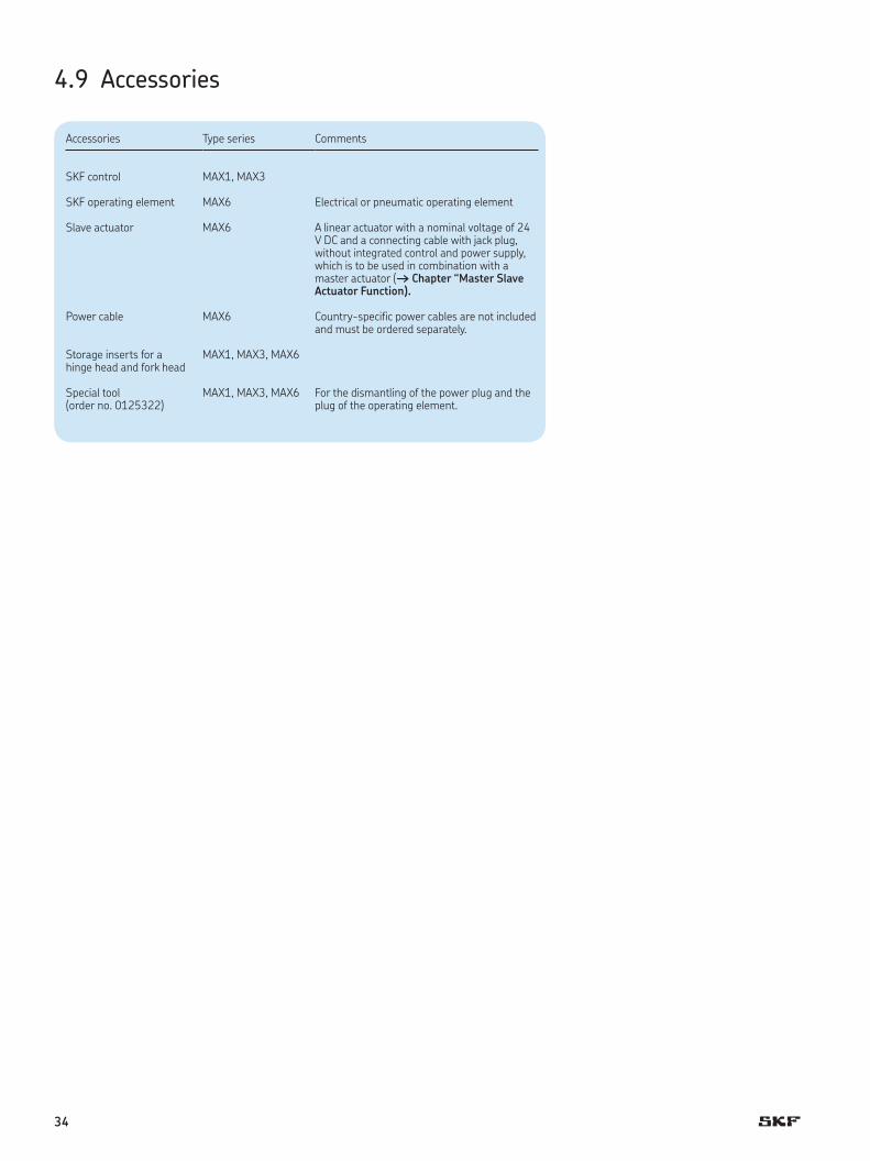
4.9 Accessories
Accessories Type series Comments
SKF control MAX1, MAX3
SKF operating element MAX6 Electrical or pneumatic operating element
Slave actuator MAX6 A linear actuator with a nominal voltage of 24 V DC and a connecting cable with jack plug, without integrated control and power supply, which is to be used in combination with a master actuator († Chapter “Master Slave Actuator Function).
Power cable MAX6 Country-specific power cables are not included and must be ordered separately.
Storage inserts for a MAX1, MAX3, MAX6hinge head and fork head
Special tool(order no. 0125322)
MAX1, MAX3, MAX6 For the dismantling of the power plug and theplug of the operating element.
34
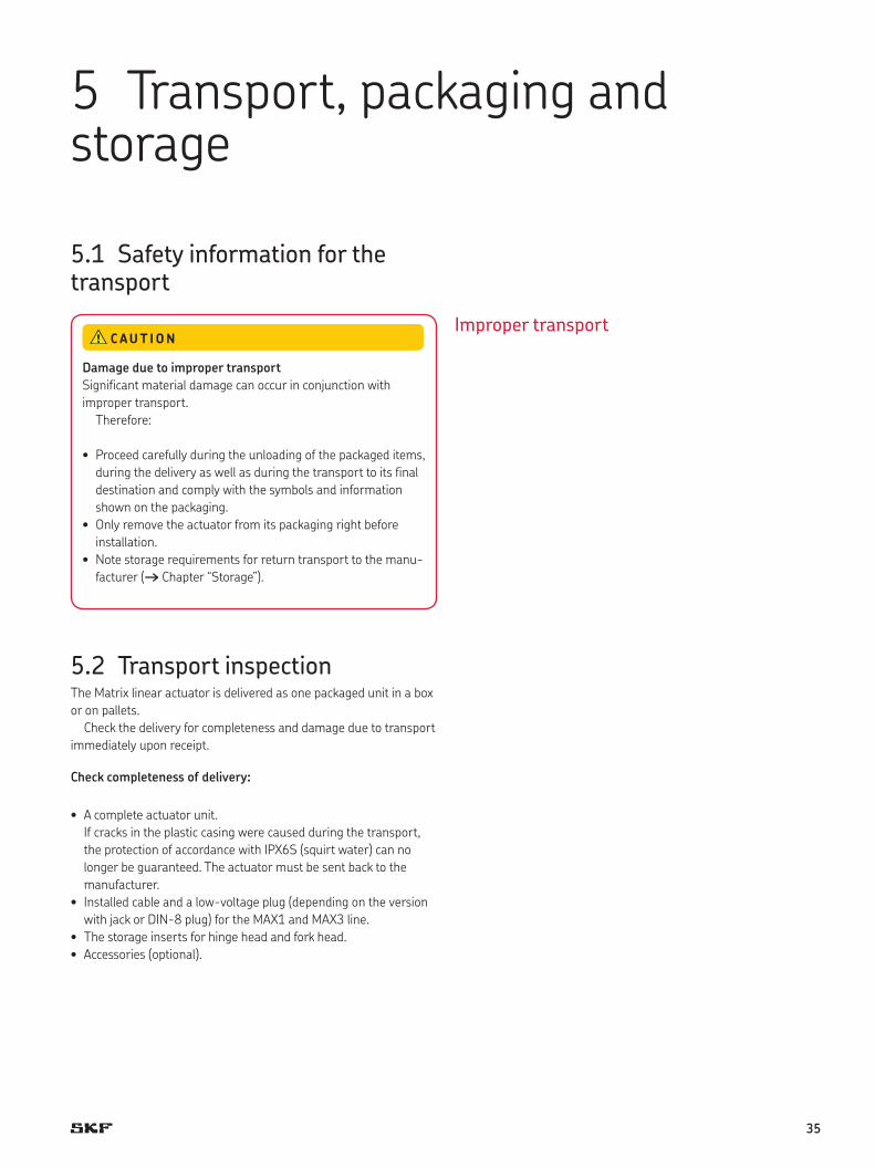
5.1 Safety information for the transport
5.2 Transport inspectionThe Matrix linear actuator is delivered as one packaged unit in a box
or on pallets.
Check the delivery for completeness and damage due to transport
immediately upon receipt.
C heck completeness of delivery:
• A complete actuator unit.
If cracks in the plastic casing were caused during the transport,
the protection of accordance with IPX6S (squirt water) can no
longer be guaranteed. The actuator must be sent back to the
manufacturer.
• Installed cable and a low-voltage plug (depending on the version
with jack or DIN-8 plug) for the MAX1 and MAX3 line.
• The storage inserts for hinge head and fork head.
• Accessories (optional).
Damage due to improper transport
Significant material damage can occur in conjunction with
improper transport.
Therefore:
• Proceed carefully during the unloading of the packaged items,
during the delivery as well as during the transport to its final
destination and comply with the symbols and information
shown on the packaging.
• Only remove the actuator from its packaging right before
installation.
• Note storage requirements for return transport to the manu-
facturer († Chapter “Storage”).
C AUT ION
5 Transport, packaging and storage
Improper transport
35

Proceed as follows in conjunction with visible exterior transport
damage:
• Do not accept delivery or do so only with reservations.
• Record scope of damage on the transport documents or on the
bill of delivery of the shipping company.
• Initiate complaint.
! Note!
Report any damage as soon as it has been recognized.
Damage claims can only be asserted within the transporter’s
applicable complaint period.
5.3 Return transportation to the manufacturer Proceed as follows for the return transport:
1 Dismantle the device if necessary († Chapter Dismantling).
2 Pack device in its original packaging. Follow storage conditions
(† Chapter Storage).
3 Send to manufacturer. The address is listed on the cover back.
5.4 PackagingFor packaging
The individual packaged pieces have been packaged appropriately
according to the expected transport conditions. Only environmentally-
friendly materials were used for the packaging.
The packaging is supposed to protect the individual components
from damage caused by the transport, corrosion and other damage
until they are ready for installation. Therefore, do not destroy the
packaging and only remove it shortly prior to the installation. Keep
packaging for possible return shipment to the manufacturer
(† Chapter 5.3).
If the packaging is to be disposed off, please note and adhere to
the following:
Environmental damage due to incorrect disposal
Packaging material consists of valuable raw materials and in
many cases they can be sensibly recycled and reused.
Therefore:
• Dispose of packaging material in an environmentally correct
way.
• Comply with locally applicable disposal regulations.
C AUT IONHandling of packaging materials
36

5.5 Storage
Pack the device in its original packaging for storage.
• Do not store outside.
• Dry and dust-free storage.
• Keep away from any aggressive media.
• Protect from UV radiation.
• Avoid mechanical vibrations.
• Storage temperature: –20 to 40 °C.
• Relative atmospheric humidity: max. 95% (no build up of
condensation).
• For storage for longer than three months, check the general con-
dition of all parts of the packaging on a regular basis. If necessary,
refresh or renew the conservation.
! Note!
It is possible that there are notices on the packaging con-
cerning the storage, which go beyond the requirements listed
here. Follow those accordingly.
37

Authorized personnel
• The installation and first start of operation may only be conducted
by specially trained experts.
• Work on the electric system may only be performed by trained
electricians.
Electric shock and moving parts hazards
Serious injury or death can be caused by touching live electrical
components and by unexpected movement of the actuator.
Be sure the system’s power supply is off and actuator is
locked out before installing.
WARN ING
Danger if restarted without authorization
When correcting faults there is danger of the energy supply
being switched on without authorization. This poses a lifethreat-
ening hazard for persons in the danger zone.
Therefore:
• Prior to starting work switch off the system and safeguard it
from being lockout.
WARN ING
Risk of injury and material damage due to incorrect
installation of the optional devices
Therefore:
• Optional devices, in particular components that are part of a
retrofitting, may only be installed in accordance with the
respective instructions (circuit diagram).
• The electromagnetic compatibility must be tested for the
routing and appropriate measures must be carried out if
necessary.
WARN ING
6 Installation and first operation
Safeguarding against restart
Electrical equipment
Optional devices
38
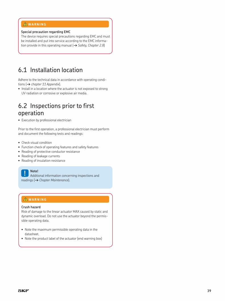
6.1 Installation location
Adhere to the technical data in accordance with operating condi-
tions († chapter 11 Appendix).
• Install in a location where the actuator is not exposed to strong
UV radiation or corrosive or explosive air media.
6.2 Inspections prior to first operation• Execution by professional electrician
Prior to the first operation, a professional electrician must perform
and document the following tests and readings:
• Check visual condition
• Function check of operating features and safety features
• Reading of protective conductor resistance
• Reading of leakage currents
• Reading of insulation resistance
Special precaution regarding EMC
The device requires special precautions regarding EMC and must
be installed and put into service according to the EMC informa-
tion provide in this operating manual († Safety, Chapter 2.8)
WARN ING
! Note!
Additional information concerning inspections and
readings († Chapter Maintenance).
Crush hazard
Risk of damage to the linear actuator MAX caused by static and
dynamic overload. Do not use the actuator beyond the permis-
sible operating data.
• Note the maximum permissible operating data in the
datasheet.
• Note the product label of the actuator (end warning box)
WARN ING
39

Before initial start-up, check that the following point have been dealt
with:
• All instructions followed, in above sections of this chapter
• grounding conductor resistance and substitute leakage currents
checked according threshold of owner usage.
• No impermissibly high side -acting forces impacting on the guide
tube unit.
• Entire stroke area unobstructed so that linear actuators cannot be
driven onto a fixed object.
• All cables secured against pinching and trapping, and properly
connected
• Electrical supply secured
• Operating device connected to the control unit.
Initial start-up
After the installation check has been completed, you can start up the
linear actuators MAX: with the LED on the operating light green,
press the corresponding operating button of the operating device.
Prior to first operation, a professional electrician must perform and
document the following tests and readings:
• Visual condition check
• Functional check of operating features and safety features
• Reading of leakage currents
• Reading of insulation resistance
! Note!
Additional information concerning inspections and
readings. († Maintenance, chapter 8) .
40

6.3 Installation
• Execution by qualified personnel
The Matrix linear actuator is attached to two elements via the fork
head and the hinge head.
1 Secure elements of the application in between which the linear
actuator will be inserted.
2 Insert storage inserts (1) at the fork head (2) and the hinge head,
if necessary.
2
1
Fig. 16
! Note!
The storage inserts that are part of the delivery can be
installed in the following cases:
• For a bolt diameter of 10 mm
• To reduce electro-magnetic charging
• As an electric insulation
• As an optimization of the storage place, so that metal doesn’t
rub on metal
Risk of injury and material damage due to manipulation of
the screws on the device
Manipulation or loosening of the screws on the device or on the
options may lead to injuries and material damage during the
operation.
Therefore:
• Never loosen screws on the device or the options.
WARN ING
41

3 Connect the fork head (1) and the hinge head (2) and the ele-
ments of the application with the fastening bolts.
1 2
Fig. 17
! Note!
Information concerning the dimensions of the drill holes
for fastening bolts can be found in the respective data sheets.
(† Appendix).
Risk of injury and material damage due to insufficient
fastening!
Only use fastening bolts and secure them adequately. Do not use
screws to install. Never loosen or otherwise manipulate screws
on actuator or options.
WARN ING
42

4 Ensure that the applied force is always centrically directed on the
actuator. († fig. 18).
Fig. 18
5 Ensure that the linear actuator is not impacted in its movement
over the entire stroke area. Consider collision tests of the
application.
6 Ensure that the motor cable cannot be squeezed, clamped or
pulled.
7 Connect linear actuator to control unit if necessary
(† Chapter “Connection to the Control Unit”).
8 Connect linear actuator to operating element
(† Chapter “Connection to Operating Element”).
9 Connect linear actuator to power supply.
(† Chapter “Connect to Power Supply”).
10 Ensure that the power plug is accessible at all times.
11 Ensure that none of the supply or control cables can be pinched
by the kinematics of the application or by the linear actuator
during the extension or retraction.
12 Ensure that the installation requirements of the options have-
been adhered to († Chapter “Requirements Concerning the
Installation of the Actuators with Options”).
13 Affix prohibition and warning labels for the application onto the
linear actuator, if necessary († Chapter “Warning labels”).
Risk of injury and material damage due to incorrect
installation!
During installation, do not subject the actuator to side-impact or
to turning forces.
WARN ING
43

6.4 Connection to the control unit
All control units which are not approved for the Matrix devices by
SKF AG are treated as third party controls.
Connect MAX1 and MAX3 to the control
! Note!
A low-voltage plug connects the device to an external
control unit. Adhere to the instructions of the operating manual
of the SKF Control unit during the connection process.
Depending on the version, the low-voltage plug has been fitted with
a jack or DIN-8 plug.
• Special tools required:
– Special tool from the manufacturer (part no. 0125322)
1 Check the sealing ring of the jack plug (arrow) and the plug for
damage.
Fig. 19
Material damage due to third-party control unit
The use of a third-party control unit may lead to material dam-
age. In conjunction with the use of a third-party control unit, the
manufacturer does not assume any liability for damage that may
be caused
Therefore:
• It is recommended to use the SKF control unit from the
manufacturer.
• When using the third-party control unit, the requirements
stipulated for the third-party control unit must be adhered to
(† Requirements for third party control units in the appendix).
C AUT ION
! Note!
Damaged sealing rings and twisted plugs can no longer
guarantee protection pursuant to IPX6S. They have to be
replaced by the manufacturer († Chapter “Transport
inspection”).
Connect jack plug to control unit
44

2 Sealing ring with Klübersynth VR 69-252 (part no. 0118037),
lightly lubricate.
3 Insert jack plug with bayonet joint (2) into the connecting socket
(1) of the control unit.
Ensure correct positioning of the groove (3).
3
1
2
Fig. 20
2
1
Fig. 21
4 Insert special tool (1) in the nut (2) of the jack plug.
5 Turn special tool (1) clockwise until the bayonet joint of the jack
plug is locked.
Damage due to wrong lubricants
The use of incorrect additives may cause significant material
damage.
Therefore:
• Only use the auxiliary products listed by the manufacturer.
C AUT ION
45

Connect DIN-8 plug to control unit.
The insertion position is dictated by the geometric shape of the plug.
The strain relief for this system is provided via attached components
of the respective SKF control unit casing.
1 Check the sealing ring of the DIN-8 plug (arrow) and the plug for
damage.
Fig. 22
! Note!
Damaged sealing rings and twisted plugs can no longer
guarantee protection pursuant to IPX6S. They have to be
replaced by the manufacturer († Chapter “Transport
inspection”).
2 Sealing ring (arrow) with Klübersynth VR 69-252
(part no. 0118037), lightly apply lubricant.
3 Insert DIN-8 plug (3) into the connecting socket (1) of the control
unit. Ensure correct positioning of the groove (2) and the lug (4).
Damage due to wrong lubricants
The use of incorrect additives may cause significant material
damage.
Therefore:
• Only use the auxiliary products listed by the manufacturer.
C AUT ION
34
2
1
Fig. 23
46

6.5 Connection to operating element
6.5.1 Connect MAX1 and MAX3 to operating element
! Note!
The device is connected to the operating element via an
external control. († Separate operating manual of the control
and the operating element).
6.5.2 Connect MAX6 to operating element
! Note!
The device is connected directly to an electric or pneu-
matic operating element. Adhere to the operating instructions
for the operating elements in regard to the connection
(† Separate operating manual).
Risk of injury and material damage due to third party
operating element
The use of a third party operating element may lead to signifi-
cant injuries or material damage.
In conjunction with the use of a third-party operating
element, the manufacturer does not assume any liability for
damage that may be caused.
Therefore:
• Only use the manufacturer’s SKF operating element.
WARN ING
47

Connect the device to electric operating element:
1 Check sealing rings (arrows) of the operating element plug and
the plug for damage.
Fig. 24
! Note!
Damaged sealing rings and twisted plugs can no longer
guarantee protection pursuant to IPX6S. They have to be
replaced by the manufacturer († Chapter “Transport
Inspection”).
2 Sealing rings (arrow) with Klübersynth VR 69-252
(part no. 0118037), lightly apply lubricant.
Damage due to wrong lubricants
The use of incorrect additives may cause significant material
damage.
Therefore:
• Only use the auxiliary products listed by the manufacturer.
C AUT ION
48
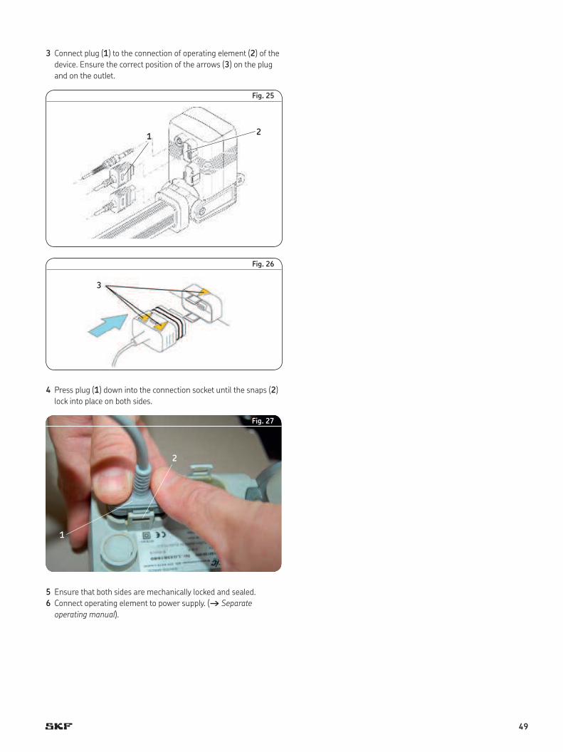
3 Connect plug (1) to the connection of operating element (2) of the
device. Ensure the correct position of the arrows (3) on the plug
and on the outlet.
12
Fig. 25
3
Fig. 26
4 Press plug (1) down into the connection socket until the snaps (2)
lock into place on both sides.
2
1
Fig. 27
5 Ensure that both sides are mechanically locked and sealed.
6 Connect operating element to power supply. († Separate
operating manual).
49

C o n n e c t t h e d e v ic e t o p n e u m a t ic o p e r a t in g e le m e n t :
1 Check gear pins of pneumatic control line for damage.
Fig. 28
2 Insert gear pins (1) into the bore holes of the rubber fitting (2).
1
2
Fig. 29
Ensure that the marking on the rubber fitting (1) aligns with the
marking on the pneumatic line (2).
12
Fig. 30
! Note!
If the connection has been switched, the linear actuator
moves in the opposite direction of the arrows on the operating
element.
50
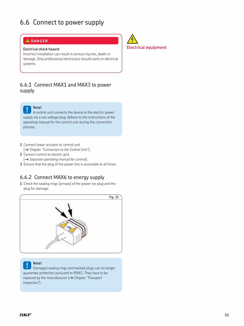
E lectrical equipment
6.6 Connect to power supply
6.6.1 Connect MAX1 and MAX3 to power supply
! Note!
A control unit connects the device to the electric power
supply via a low voltage plug. Adhere to the instructions of the
operating manual for the control unit during the connection
process.
1 Connect linear actuator to control unit
(† Chapter “Connection to the Control Unit”).
2 Connect control to electric grid
(† Separate operating manual for control).
3 Ensure that the plug of the power line is accessible at all times.
6.6.2 Connect MAX6 to energy supply1 Check the sealing rings (arrows) of the power ine plug and the
plug for damage.
Fig. 31
Electrical shock hazard
Incorrect installation can result in serious injuries, death or
damage. Only professional electricians should work on electrical
systems.
DANGER
! Note!
Damaged sealing rings and twisted plugs can no longer
guarantee protection pursuant to IPX6S. They have to be
replaced by the manufacturer († Chapter “Transport
Inspection”).
51

2 Sealing rings (arrow) with Klübersynth VR 69-252
(part no. 0118037), lightly apply lubricant.
1
2
Fig. 32
3 Connect plug of the electric cord (1) to the co nection of the power
line (2) of the device.
Ensure the correct position of the arrows (3) on the plug and on
the outlet.
3
Fig. 33
Damage due to wrong lubricants
The use of incorrect additives may cause significant material
damage.
Therefore:
• Only use the auxiliary products listed by the manufacturer.
C AUT ION
52

4 Press plug (1) down into the connection socket until the snaps (2)
lock into place on both sides.
2
1
Fig. 34
5 Ensure that both sides are mechanically locked and sealed.
6 Connect electric cord to power supply.
7 Ensure that the plug of the power line is accessible at all times.
53
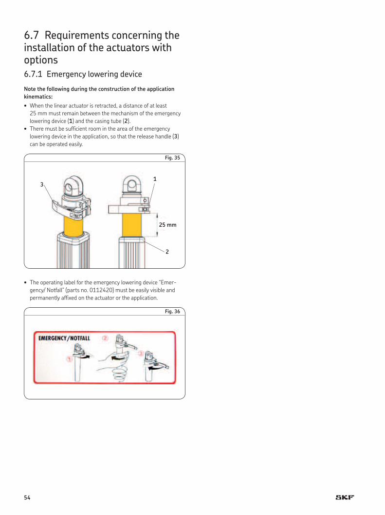
6.7 Requirements concerning the installation of the actuators with options 6.7.1 Emergency lowering device
Note the following during the construction of the application
kinematics:
• When the linear actuator is retracted, a distance of at least
25 mm must remain between the mechanism of the emergency
lowering device (1) and the casing tube (2).
• There must be sufficient room in the area of the emergency
lowering device in the application, so that the release handle (3)
can be operated easily.
31
25 mm
2
Fig. 35
• The operating label for the emergency lowering device “Emer-
gency/ Notfall” (parts no. 0112420) must be easily visible and
permanently affixed on the actuator or the application.
Fig. 36
54

6.7.2 Quick adjustment N o te the following during the construction of the application
kinematics:
• In the application there must be enough room in the area of the
knob (1) or the Bowden cable (2), so that the two elements can be
operated easily.
1
2
Fig. 37
• The Bowden cable between the linear actuator and the operating
element has to be installed so that it is not pinched or affected by
the movements of the linear actuator.
6.7.3 Electrical pinch protection Note the following during the installation of the linear actuator
with electric pinch protection.
• The gear pin (2) at the hinge head (1) may not be jammed.
• Use fastening bolts with ∅12 h7 for the mounting of the hinge
head.
12
Fig. 38
55

• Ensure after the installation that the installed linear actuator can
be moved inside the elongated hole (2) of the hinge head (1).
21
1 mm
F ig. 39
6.7.4 Mechanical pinch protectionAdhere to the larger installation measures for the use of a linear
actuator with pinch protection. († Data sheets for linear actuator
and accessories in the appendix).
6.7.5 Master-slave actuator functionThe master-slave actuator function features an additional actuator
(slave actuator) which is connected to the Matrix MAX6 linear actua-
tor via a jack plug (e. g. Matrix MAX1 or MAX3). Note the following
during the connection:
• Only one linear actuator with a power supply voltage of 24 V DC
may be connected.
• When both actuators (master actuator and slave actuator) run
together, the total power may not exceed 6 A
Connect slave actuator to Matrix MAX6
• Special tools required:
– Special tool from the manufacturer (part no. 0125322)
1 Check sealing ring of jack plug (arrow) and the jack plug of the
slave actuator for damage.
Fig. 40
56

2 Sealing ring (arrow) with Klübersynth VR 69-252
(part no. 0118037) lightly apply grease.
3 Insert jack plug with bayonet joint (1) into the connecting sockets
(2) of the device († fig. 41).
Ensure correct positioning of the groove (3) († fig. 42).
2
1
Fig. 41
3
Fig. 42
! Note!
Damaged sealing rings and twisted plugs can no longer
guarantee protection pursuant to IPX6S. They have to be
replaced by the manufacturer († Chapter “Transport Inspection).
Damage due to wrong lubricants
The use of incorrect additives may cause significant material
damage.
Therefore:
• Only use the auxiliary products listed by the manufacturer.
C AUT ION
57

4 Insert special tool (1) in the groove (2) of the jack plug.
5 Turn special tool (1) clockwise until the bayonet joint of the jack
plug is locked.
6 Connect slave actuator to energy supply. († Chapter “Connect to
Power Supply”).
2
1
Fig. 43
58

7.1 Safety
R i s k of injury through contact with the fork head
Therefore:
• Do not let objects or body parts come in contact with the fork
head of the actuator.
C AUT ION
Risk of crushing
While moving onto solid objects, the force of the device may
cause injuries.
Therefore:
• Ensure that there are no persons in the stroke area of the
device while in operation.
• Take note of maximum permissible operating data for the
device († Data sheets in Chapter 11 Appendix).
• Never tamper with the elements that are connected to the
device while the device is in operation.
DANGER
Material damage due to static and dynamic overload of the
device
Static and dynamic overload can lead to damage and failure of
the device.
Therefore:
• Adhere to maximum permissible operating data for the device
(† Data sheets in the Appendix).
• Never exceed nominal load.
• Never tamper with the elements that are connected to the
device while the device is in operation.
C AUT ION
7 Operation
59

7.2 Turn on
!Note!
The device does not feature its own operating control ele-
ments. The operation takes place via a separate operating ele-
ment († Separate operating manual).
7.3 Turn off
! Note!
The device does not feature its own operating elements.
The operation takes place via a separate operating element
(† Separate operating manual).
Actuator may be damaged if liquids penetrate the actuator
during extension and retra c t io n . K eep liquids away.
C AUT ION
Material damage through overheating
An overheating of the device can cause damage.
Therefore:
• Only use control integrated thermal switch.
• Never exceed nominal load.
• Always adhere to idle times and operating times.
(† Chapter “Technical Data”).
C AUT ION
60

7.4 Action before use
1 Ensure that there are no persons or objects in the stroke area of
the device.
For options:
2 Ensure that the release handle of the emergency lowering device
(1) is closed until it touches the arrester or that the mechanism of
the quick adjustment is locked. († Chapter “Operate Emergency
Lowering Device”).
1
Fig. 44
3 Ensure that the mechanism of a quick adjustment (1) is locked
(† Chapter “Operate Quick Adjustment”).
1
Fig. 45
61
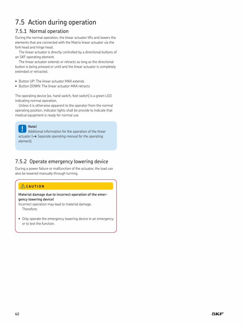
7.5 Action during operation7.5.1 Normal operationDuring the normal operation, the linear actuator lifts and lowers the
elements that are connected with the Matrix linear actuator via the
fork head and hinge head.
The linear actuator is directly controlled by a directional buttons of
an SKF operating element.
The linear actuator extends or retracts as long as the directional
button is being pressed or until and the linear actuator is completely
extended or retracted.
• Button UP: The linear actuator MAX extends
• Button DOWN: The linear actuator MAX retracts
The operating device (ex. hand switch, foot switch) is a green LED
indicating normal operation.
Unless it is otherwise apparent to the operator from the normal
operating position, indicator lights shall be provide to indicate that
medical equipment is ready for normal use
!Note!
Additional information for the operation of the linear
actuator († Separate operating manual for the operating
element).
7.5.2 Operate emergency lowering deviceDuring a power failure or malfunction of the actuator, the load can
also be lowered manually through turning.
Material damage due to incorrect operation of the emer-
gency lowering device!
Incorrect operation may lead to material damage.
Therefore:
• Only operate the emergency lowering device in an emergency
or to test the function.
C AUT ION
62

To engage the emergency lowering device, proceed as follows:
1 Open release handle (1).
2 Turn actuator (2) clockwise toward the arrow. The actuator moves
downward. The required manually applied force depends on the
load.
2
Fig. 47
Fig. 46
1
Risk of crashing and material damage due to an unintended
lowering
Unintended lowering while carrying a load may cause injuries
and material damage.
Therefore:
• Immediately stop the operation in the event of excessive exer-
tion of force or independent lowering and initiate repairs
through the manufacturer.
C AUT ION
63

3 Little oppositionists reached, close the release handle (3) all the
way to the arrester.
7.5.3 Operate quick adjustment
Adjust actuator with the button
1 Turn button (1) by 90° and unlock.
1
Fig. 49
Fig. 48
1
Material damage due to incorrect operation of the quick
adjustment function
Incorrect operation may lead to material damage.
Therefore:
• Only operate the quick adjustment function in an emergency
or to test the function.
C AUT ION
64

2 Ensure that the head (1) is in position (2).
3 Manually retract actuator (3).
1
23
Fig. 50
Risk of crashing and material damage due to an unintended
lowering
Depending on the construction and the load, the linear actuator
can be quickly retracted. Unintended lowering while carrying a
load may cause injuries and material damage
Therefore:
• The part of the application that is to be lowered (e. g. head
and foot piece in a bed) must be retained at all cost during the
lowering.
• In its retracted position of the application, the portion that is
to be lowered must rest on a solid arrester (e. g. bed frame).
C AUT ION
65

4 Turn button (1) by 90° again and unlock
Adjust speed of the lowering device.
1 The speed of the lowering device may be adjusted via two oppos-
ing adjusting screws (1).
1
Fig. 51
Adjust actuator with Bowden cable
For adjustments via the Bowden cable, the Bowden cable (1) is
operated via an operating element on the application.
1
Fig. 52
Material damage
The adjusting screws are not secured and can be entirely
unscrewed and can therefore be lost.
Therefore:
• Do not completely unscrew adjusting screws.
C AUT ION
66

A f ter rescue measures
7.6 Disengagement in case of emergencyIn hazardous situations, all movements of the device must be
stopped as quickly as possible and the power supply must be
turned off.
Proceed as follows in hazardous situations:
1 Immediately engage emergency shut-off, if present, or cut off
power for actuator († Chapter “Shut down MAX1 and MAX3“,
“Shut down MAX6“).
2 Evacuate people from the hazard zone, initiate first aid measures.
3 Notify doctor and fire department, if necessary.
4 Notify responsible person on-site.
5 Keep access paths open for rescue vehicles.Order specialized staff
to repair malfunction.
6 Based on severity of emergency, notify the authorities
if necessary.
7 Order specialized staff to repair malfunction.
8 Check the device and application that uses the device prior to
restarting the operation and ensure that all safety equipment is
installed and fully functional.
Do not restart until all persons are outside the hazard zone.
Check the device and application that uses the device prior to
restarting the operation and ensure that all safety equipment is
installed and fully functional
WARN ING
67

7.6.1 Shut down MAX1 and MAX31 Pull the power line plug of the control unit out of the power outlet.
2 Pull the low-voltage plug (Jack plug or DIN-8 plug) of the cable of
the device out of the connecting socket of control unit († Refer to
paragraph below).
Pull jack plug out of control unit
Proceed as follows to pull jack plug out of the connection outlet of
the control unit:
• Special tools required:
– Special tool from the manufacturer (part no. 0125322)
1 Insert special tool (1) in the groove (2) of the jack plug.
2 Turn special key (1) counter-clockwise until the bayonet joint of
the jack plug is unlocked.
1
2
Fig. 53
3 Pull jack plug (1) out of the connection outlet (2) of the control
unit (arrow).
2
1
Fig. 54
68

7.6.2 Shut down MAX61 Pull the power line plug (connected with
connection (1) out of the power outlet.
Fig. 55
7.7 Action after use
Separate the actuator from the power
supply.
69

P ersonnel
• The maintenance work described herein can be performed by the
operator unless otherwise indicated.
• Some maintenance tasks should only be executed by especially
trained, qualified personnel, or exclusively by the manufacturer;
specific reference will be made in each case in the description of
the respective maintenance task.
• Only professional electricians should perform work on the electri-
cal equipment.
Electrical shock hazard
Incorrect installation can result in serious injuries, death or
damage. Only professional electricians should work on electrical
systems.
DANGER
Danger if restarted without authorization
When correcting faults, there is danger of the energy supply
being switched on without authorization. This poses a lifethreat-
ening hazard for persons in the danger zone.
Therefore:
• Prior to starting work, switch off the system and safeguard it
from being lockout.
DANGER
8 Maintenance
Electrical equipment
Safeguarding against restart
70

8.1 Maintenance plan
Maintenance tasks that are required for optimal and trouble-free
operation are described in the sections below.
If increased wear is detected during regular inspections, shorten
the required maintenance intervals according to the actual indica-
tions of wear.
Linear actuator Matrix maintenance plan
Interval Maintenance work To be carried out by
Daily Check actuator for visible damage Operator(† Chapter “Check of Visual Condition”).
Clean off dust and dirt if necessary(† Chapter “Cleaning”).
Operator
Monthly Function check of operating features and safety features († Chapter “Inspections and Readings”).
Qualified personnel
Check tight fit of the device to the fork head and hinge Qualified personnelhead, correct it if necessary Check connection for tight fit.
Annually Reading of protective conductor resistance(† Chapter “Inspections and Readings“).
Professional electrician
Reading of leakage currentsn(† Chapter “Inspections and Readings“).
Professional electrician
Reading of insulation resistance († Chapter Professional electrician“Inspections and Readings“).
Check labels and warning notices for damage and Qualified personnelreplace if necessary.
Check plug for tight fit. Professional electrician
Check sealing O-rings for damage Professional electrician(† Chapter “Check Sealing Funktion of Plug”).
Definition through Conduct visual inspection of the condition of thethe processor permanent safeguard and the routing of the supply and
control cable within the application. Cable routingelements may not be loose or broken.
Options
Semi- Check options for visible damage Qualified personnelannually
Check functionality of emergency lowering device Qualified personnelunder nominal load († Chapter “Check Options”).
Check functionality of electric pinch protection undernominal load († Chapter “Check Options”).
Qualified personnel
Check functionality of quick adjustment Qualified personnel(† Chapter “Check Options”).
! Note!
If the linear actuator is used outside of the environmental
conditions specified earlier in this manual, check such compo-
nents once a month for any changes such as oxidation or
sedimentation.
71

8.2 Maintenance work
8.2.1 CleaningTo be performed by operator
C lean line actuator:
1 Separate the device from the energy supply.
2 Clean dirty parts with a damp cloth.
Cleaning of emergency lowering device, quick adjustment
device:
1 Separate the device from the energy supply.
2 Clean emergency lowering mechanism or quick adjustment
device with a damp cloth and prophyl alcohol.
8.2.2 Inspections and readings• Execution by professional electrician.
• The inspections and readings must be performed as stipulated by
the applicable standards and regulations. The list of the applicable
standards can be found in the appendix.
• The inspections must be documented († “Service Log”).
The external metal parts are not reliably connected with the projec-
tive conductor, with the exception of the external protective conduc-
tor connection. The separation/insulation takes place either through
a double or reinforced insulation or through an intermediate circuit
that is connected with a protective conductor within the housing.
A reading of the protective conductor resistance is therefore not
possible. Potential connections only take place by accident due to
metal parts that touch each other more or less forcefully.
Damage due to incorrect cleaning
Therefore:
• Do not use any aggressive cleaning agents. Water used for
cleaning including the chemical additives must be pH-neutral.
• Liquids must not touch the actuator during the retraction or
extension.
• Only use the auxiliary materials listed by the manufacturer.
• Emergency lowering mechanism for quick adjustment system
may not be treated with oil, grease or other lubricants.
• No steam jets or pressure washers may be used for cleaning.
• Other cleaning agents or cleaning devices may only be utilized
with the manufacturer’s approval.
C AUT ION
Measuring of the protectiveconductor resistance (MAX6)
72

Complete the following entries in the service log:
• Name of the executing body (company, department)
• Names of the staff on duty
• Identification of the device/system (type, serial number, inventory
number) and the respective accessories
• Completed inspections and readings
• Scope and results of the inspections
• Measuring method, measuring device, measuring results for
readings
• Overall assessment
• Date and signature of the assessing person; personal coding is a
viable alternative for IT applications.
8.2.3 Check sealing function of plugTo be performedby professional electrician
Check sealing function of DIN-8 plug
1 Separate the device from the energy supply.
2 Check sealing O-ring (3) of the DIN-8 plug (2) for damage.
3 Ensure that there is no irregular gap between the DIN-8 plug (2)
and the connection outlet (1) of the housing.
4 If sealing O-rings (3) are damaged, have the manufacturer
replace them.
5 If there is no damage, reconnect the device with the energy
supply.
1
3
2
Fig. 56
Service log
73
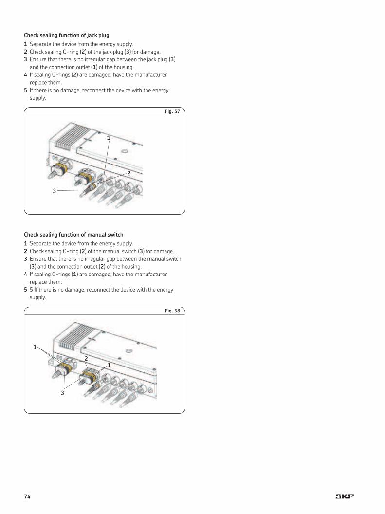
Check sealing function of jack plug
1 Separate the device from the energy supply.
2 Check sealing O-ring (2) of the jack plug (3) for damage.
3 Ensure that there is no irregular gap between the jack plug (3)
and the connection outlet (1) of the housing.
4 If sealing O-rings (2) are damaged, have the manufacturer
replace them.
5 If there is no damage, reconnect the device with the energy
supply.
2
1
3
Fig. 57
Check sealing function of manual switch
1 Separate the device from the energy supply.
2 Check sealing O-ring (2) of the manual switch (3) for damage.
3 Ensure that there is no irregular gap between the manual switch
(3) and the connection outlet (2) of the housing.
4 If sealing O-rings (1) are damaged, have the manufacturer
replace them.
5 5 If there is no damage, reconnect the device with the energy
supply.
2
3
1
1
Fig. 58
74
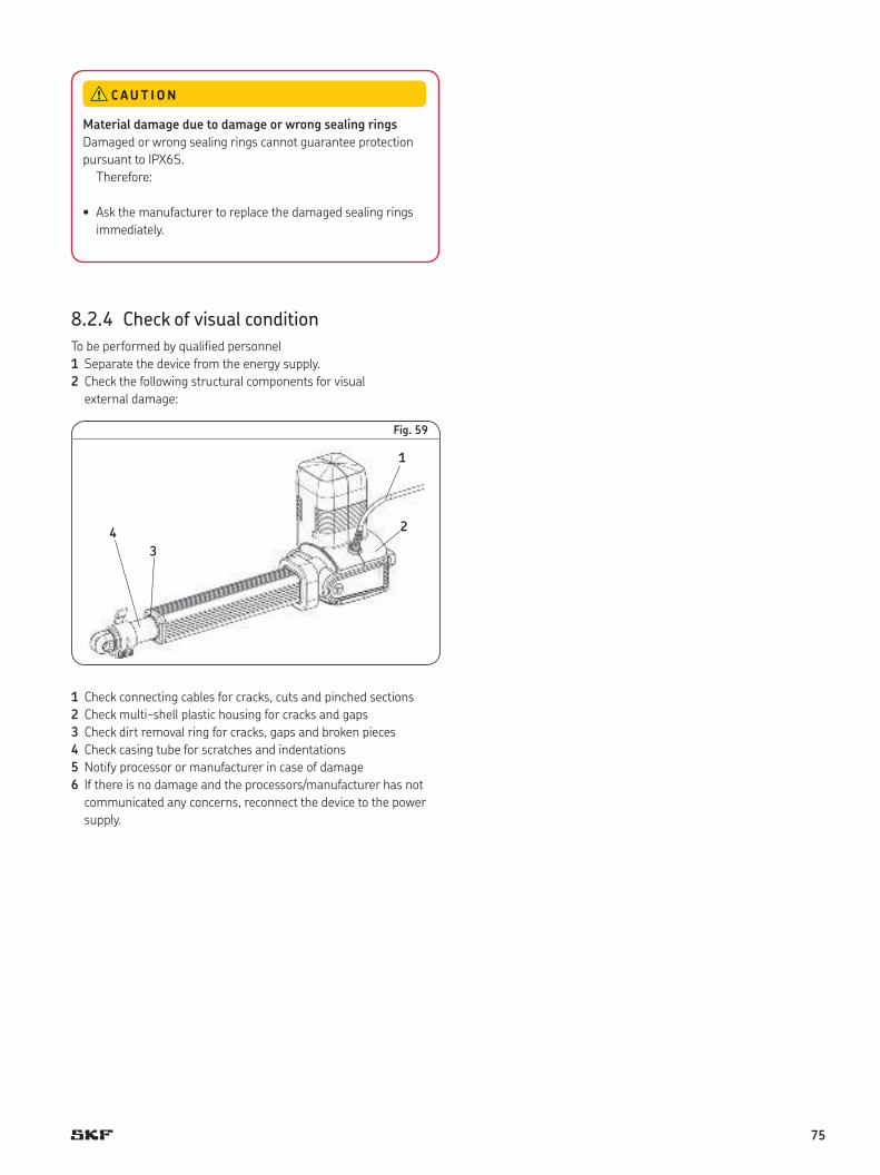
8.2.4 Check of visual condition
To be performed by qualified personnel
1 Separate the device from the energy supply.
2 Check the following structural components for visual
external damage:
1
24
3
Fig. 59
1 Check connecting cables for cracks, cuts and pinched sections
2 Check multi-shell plastic housing for cracks and gaps
3 Check dirt removal ring for cracks, gaps and broken pieces
4 Check casing tube for scratches and indentations
5 Notify processor or manufacturer in case of damage
6 If there is no damage and the processors/manufacturer has not
communicated any concerns, reconnect the device to the power
supply.
Material damage due to damage or wrong sealing rings
Damaged or wrong sealing rings cannot guarantee protection
pursuant to IPX6S.
Therefore:
• Ask the manufacturer to replace the damaged sealing rings
immediately.
C AUT ION
75

8.2.5 Check options
Check functionality of emergency lowering device,
quick adjustment
• Ensure that there is no excessive application of force, extremely
slick movement (independent downward movement of the actua-
tor after opening the release handle) under nominal load
(† Chapter “Operation” † “Operate Emergency Lowering Device”,
“Operate Quick Adjustment”).
Check functionality for electrical pinch protection
• Ensure that the gear pin (1) is lifted in the backload direction to
turn off the actuator.
1
Fig. 60
! Note!
Inform the manufacturer in case of damage or
malfunction.
8.3 Measures after completed maintenanceUpon completion of the maintenance work, the following steps have
been executed prior to restarting the device.
1 Check all previously loosened screw connections for a tight fit.
2 Ensure that all used tools, materials and other equipment have
been removed from the work area.
3 Clean work area and remove potential spills such as e. g. liquids,
processing material or similar.
4 Ensure that all safety measures of the system work without a
problem.
5 Check functions.
6 Document the inspections in the service log.
76

The following chapter describes potential causes for disruptions and
the work that is necessary to restore operation.
In the event of more frequent malfunctions, shorten the mainte-
nance intervals according to the actual load.
Contact the manufacturer concerning malfunctions which are not
solved by the subsequent notices; see service address on the back
cover.
Personnel
• Unless indicated otherwise, the work described herein to solve
malfunctions may be performed by the operator.
• Some work may only be carried out by qualified personnel, which
is specifically indicated in the description of the individual
malfunction.
• Work on the electric system may only be performed by profes-
sional electricians.
Electric shock and moving parts hazards
Serious injury or death can be caused by touching live electrical
components and by unexpected movement of the actuator.
Be sure power supply is off and actuator is locked out before
installing.
DANGER
Danger if restarted without authorization
When correcting faults, there is danger of the energy supply
being switched on without authorization. This poses a lifethreat-
ening hazard for persons in the danger zone.
Therefore:
• Prior to starting work, switch off the system and safeguard it
from being lockout.
DANGER
9 Malfunctions
Electrical equipment
Safeguarding against restart
77

B ehavior during malfunctions
In principle:
1 In the event of a malfunction that may present an immediate
danger to persons or assets, turn off the actuator or control unit
immediately and safeguard against a restart.
2 Determine cause of malfunction.
3 Depending on the type of a malfunction, have it repaired by quali-
fied personnel.
4 Inform responsible party on-site concerning malfunction.
! Note!
The following malfunction table provides information
as to who is authorized to perform the repair.
Risk of injury and material damage due to incorrect repair
of malfunction
The Matrix linear actuator is not designed for repair work.
Incorrect repair of a malfunction may lead to personal injury
or material damage.
Therefore:
• Never loosen the screws on the linear actuator or try to open
the linear actuator.
• In the event of a malfunction that cannot be fixed by adhering
to the subsequent notices, dismantle the device and send it to
the manufacturer for repair. († Chapter “Transport, Packag-
ing and Storage”).
DANGER
Incorrect repair of malfunction
78

9.1 Malfunction table
9.1.1 Matrix MAX1 and MAX3
Ma lfunction Possible cause Repair malfunction To be repaired by
Linear actuatordoesn’t move
No supply voltage. Check power supply. Professional electrician
Lack of plug contact or plug has not beeninserted properly.
Plug contacts:Device control unit, control of voltage network.Check control operating element.
Operator
Defective network cable or power plug. Supply cable and plug of the lines:Check device control unit, control of voltagenetwork control operating element for damage,if necessary replace defective elements.
Professional electrician
Obstacle in the stroke area of the linearactuator.
Remove all obstacles in the stroke area. Operator
Incorrect load. Measure static and dynamic load and compare Qualified personnelwith information concerning the product label.If the load capacity is exceeded, check thenominal load and install stronger actuator ifnecessary.
Defective control unit/operating element. Identification of defect concerning the SKFcontrol unit; if necessary replace defectivecontrol, operating element.
Qualified personnel
Lifespan of the device is exceeded. If the actuator is older than 10 years and has Qualified personnelperformed more than 10 000 double strokeswith a 200 mm hub, the actuator needs to bereplaced.
Linear actuator cannot be set in motion by Exchange device. Qualified personnelany of the above listed measures.
Linear actuator cannotbe lifted
Obstacle in the stroke area of the linearactuator.
Remove all obstacles in the stroke area. Operator
Incorrect load. Remove all loads that are on the elements. Operator
Defective screw nut. Exchange device. Qualified personnel
Significantly reduced speed Obstacle in the stroke area of the linearactuator.
Remove all obstacles in the stroke area. Operator
Incorrect load. Remove all loads that are on the elements. Operator
Defective motor, gear or screw nut Exchange device. Qualified personnel
Significantly increase ofnoises during operation
Obstacle in the stroke area of the linearactuator.
Remove all obstacles in the stroke area. Operator
Incorrect load. Remove all loads that are on the elements. Operator
Defective motor, gear orball screw nut.
Exchange device. Qualified personnel
79

9.1.2 Matrix MAX6
Malfunction Possible cause Repair malfunction To be repaired by
Linear actuatordoesn’t move
No supply voltage. Check power supply. Professional electrician
Lack of plug contact or plug has not beeninserted properly.
Plug contacts:Device-electric grid, check deviceoperatingelement.
Operator
Defective network cable or power plug. Supply cable and plug of the lines:Device-electric grid, check for damage ondevice-operating element, if necessary replacedefective elements.
Professional electrician
Obstacle in the stroke area of the linearactuator.
Remove all obstacles in the stroke area. Operator
Incorrect load. Measure static and dynamic load and Qualified personnelcompare with information on the typelabel. If the load capacity is exceeded,replace the device.
Lifespan of the device is exceeded. If the actuator is older than 10 years and has Qualified personnelperformed more than 10 000 double strokeswith a 200 mm hub, the actuator needs to bereplaced.
Linear actuator cannot be set in motion by Exchange device. Qualified personnelany of the above listed measures.
Linear actuator cannot beoperated
Incorrect operatingelement.
Compare the information on the type label ofthe operating element with the information onthe type sign of the device. If the manufacturerof the operating element is not authorized forthe Matrix actuator, replace incorrect operatingelement through SKF operating elementauthorized by the manufacturer.
Qualified personnel
Defective SKF operating element. Conduct malfunction identification of the SKFoperating element, if necessary replaceoperating element.
Qualified personnel
Defective screw nut. Exchange device. Qualified personnel
Linear actuator cannot belifted
Obstacle in the stroke area of the linearactuator.
Remove all obstacles in the stroke area. Operator
Incorrect load. Remove all loads that are on the elements. Operator
Defective ball screw nut. Exchange device. Qualified personnel
Significantly reduced speed Obstacle in the stroke area of the linearactuator.
Remove all obstacles in the stroke area. Operator
Incorrect load. Remove all loads that are on the elements. Operator
Defective motor, gear orball screw nut.
Exchange device. Qualified personnel
Significantly increase noisesduring operation
Obstacle in the stroke area of the linearactuator.
Remove all obstacles in the stroke area. Operator
Incorrect load. Remove all loads that are on the elements. Operator
Defective motor, gear or ball screw nut. Exchange device. Qualified personnel
80

9.2 Start of operation after fixing malfunctionAfter the malfunction has been fixed, perform the steps from the
Installations chapter prior to restart.
81

P ersonnel
• The dismantling may only be carried out by specifically qualified
personnel.
• Work on the electric system may only be performed by profes-
sional electricians.
Electric shock and moving parts hazards
Serious injury or death can be caused by touching live electrical
components and by unexpected movement of the actuator.
Be sure power supply is off and actuator is locked out before
installing.
DANGER
Risk of injury due to incorrect dismantling
Stored residual power, sharp-edged components, pins and cor-
ners on the individual components or at the required tools can
cause serious injuries.
Therefore:
• Ensure there is ample of space for the dismantling prior to
starting with the work.
• Use caution when working with open, sharp-edged structural
components.
• Ensure order and cleanliness at the dismantling site! Loosely
stacked structural components or structural components and
tools on the floor may present a source for accidents.
• Dismantle structural components professionally pursuant to
applicable local regulations.
• Secure structural components in a way so they would not be
able to fall or tip over.
• Contact the manufacturer if you have any questions or
concerns.
WARN ING
10 Dismantling
Electrical equipment
Basic Information
82
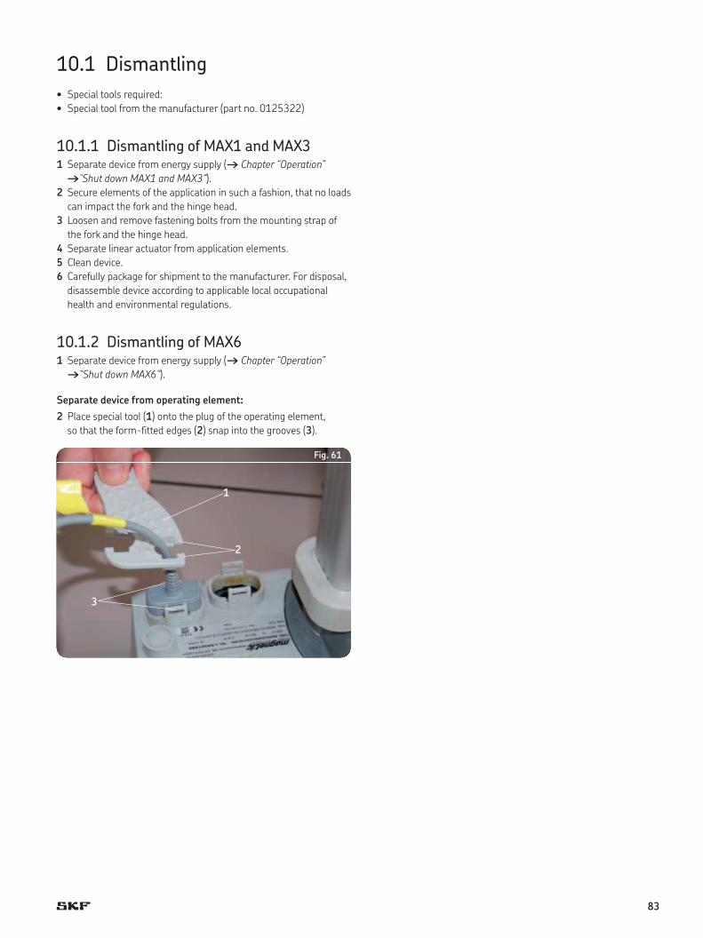
10.1 Dismantling
• Special tools required:
• Special tool from the manufacturer (part no. 0125322)
10.1.1 Dismantling of MAX1 and MAX31 Separate device from energy supply († Chapter “Operation”
†“Shut down MAX1 and MAX3“).
2 Secure elements of the application in such a fashion, that no loads
can impact the fork and the hinge head.
3 Loosen and remove fastening bolts from the mounting strap of
the fork and the hinge head.
4 Separate linear actuator from application elements.
5 Clean device.
6 Carefully package for shipment to the manufacturer. For disposal,
disassemble device according to applicable local occupational
health and environmental regulations.
10.1.2 Dismantling of MAX61 Separate device from energy supply († Chapter “Operation”
†“Shut down MAX6“).
Separate device from operating element:
2 Place special tool (1) onto the plug of the operating element,
so that the form-fitted edges (2) snap into the grooves (3).
2
3
1
Fig. 61
83

3 Push down special tool until the locking mechanism on the plug
is opened.
Fig. 62
4 Pull out plug (1).
1
Fig. 63
Separate electric cord from the actuator:
5 Carry out steps 2 to 4 for the plug of the power line (1).
3
1
Fig. 64
84
Sever connection to the slave actuator, if it exists:
6 Place special tool (1) onto the nut (2) of the jack plug.
7 Turn special tool (1) counter-clockwise until the bayonet joint
of the jack plug is unlocked.
1
2
Fig. 65
8 Pull jack plug (1) out of the connection outlet (2) of the actuator.
2
1
Fig. 66
9 Secure elements of the application in such a fashion, that no
loads can impact the fork and the hinge head.
10 Loosen and remove fastening bolts from the mounting strap
of the fork and the hinge head.
11 Separate linear actuator from application elements.
12 Clean actuator.
13 Careful packaging for shipment to the manufacturer. For
disposal, disassemble device according to applicable local
occupational health and environmental regulations.
85

10.2 Disposal
To the extent that no take-back or disposal agreement has been put
in place, disassembled components should be recycled.
• Dispose of metals and plastic components at an appropriate
recycling centre.
• Sort remaining components based on the respective material
and dispose of according to applicable local occupational health
and environmental regulations.
The local municipal authorities or specialized waste management
companies can provide information concerning environmentally
appropriate disposal.
D a m a g e can be caused to the environment due to incorrect
disposal
Electronic waste, electronic components, lubricants and other
additives are subject to special waste treatment regulations and
may only be disposed of by approved specialized companies!
C AUT ION
86

Notes
87

® SKF and MATRIX are registered trademarks of the SKF Group.
© SKF Group 2017 The contents of this publication are the copyright of the publisher and may not be reproduced (even extracts) unless prior written permis-sion is granted. Every care has been taken to ensure the accuracy of the information contained in this publication but no liability can be accepted for any loss or damage whether direct, indirect or consequential arising out of the use of the information contained herein.
PUB MT/I1 11133/2 EN · May 2017
Please contact:
SKF Actuation System (Liestal) AGOristalstrasse 97
4410 Liestal
Switzerland
Tel.: +41 61 925 4111
Fax: +41 61 921 3704
skf.com