mathieson, a., cardoni, a., cerisola, n., and lucas, m ...eprints.gla.ac.uk/104347/1/104347.pdf2...
TRANSCRIPT

s
Mathieson, A., Cardoni, A., Cerisola, N., and Lucas, M. (2015) Understanding nonlinear vibration behaviours in high-power ultrasonic surgical devices. Proceedings of the Royal Society of London Series A: Mathematical, Physical and Engineering Sciences, 471, 20140906.
Copyright © 2015 The Authors
This work is made available the Creative Commons Attribution 4.0 License (CC BY 4.0)
Version: Published http://eprints.gla.ac.uk/104347 Deposited on: 25 March 2015
Enlighten – Research publications by members of the University of Glasgow http://eprints.gla.ac.uk
rspa.royalsocietypublishing.org
ResearchCite this article:Mathieson A, Cardoni A,Cerisola N, Lucas M. 2015 Understandingnonlinear vibration behaviours in high-powerultrasonic surgical devices. Proc. R. Soc. A 471:20140906.http://dx.doi.org/10.1098/rspa.2014.0906
Received: 21 November 2014Accepted: 11 February 2015
Subject Areas:biomedical engineering,mechanical engineering
Keywords:power ultrasonics, ultrasonic surgery,experimental modal analysis,nonlinear behaviour
Author for correspondence:Margaret Lucase-mail: [email protected]
Electronic supplementary material is availableat http://dx.doi.org/10.1098/rspa.2014.0906 orvia http://rspa.royalsocietypublishing.org.
Understanding nonlinearvibration behaviours inhigh-power ultrasonicsurgical devicesAndrewMathieson1, Andrea Cardoni2,
Niccolò Cerisola3 and Margaret Lucas1
1School of Engineering, University of Glasgow, Glasgow, UK2Pusonics SL, Arganda del Rey, Spain3Mectron S.p.A, Carasco, GE, Italy
Ultrasonic surgical devices are increasingly usedin oral, craniofacial and maxillofacial surgeryto cut mineralized tissue, offering the surgeonhigh accuracy with minimal risk to nerve andvessel tissue. Power ultrasonic devices operatein resonance, requiring their length to be a half-wavelength or multiple-half-wavelength. For bonesurgery, devices based on a half-wavelength haveseen considerable success, but longer multiple-half-wavelength endoscopic devices have recentlybeen proposed to widen the range of surgeries.To provide context for these developments, someexamples of surgical procedures and the associateddesigns of ultrasonic cutting tips are presented.However, multiple-half-wavelength components,typical of endoscopic devices, have greater potentialto exhibit nonlinear dynamic behaviours that have ahighly detrimental effect on device performance.Through experimental characterization of thedynamic behaviour of endoscopic devices, itis demonstrated how geometrical features influencenonlinear dynamic responses. Period doubling, aknown route to chaotic behaviour, is shown to besignificantly influenced by the cutting tip shape,whereas the cutting tip has only a limited effect onDuffing-like responses, particularly the shape ofthe hysteresis curve, which is important for devicestability. These findings underpin design, aimingto pave the way for a new generation of ultrasonicendoscopic surgical devices.
2015 The Authors. Published by the Royal Society under the terms of theCreative Commons Attribution License http://creativecommons.org/licenses/by/4.0/, which permits unrestricted use, provided the original author andsource are credited.
on March 25, 2015http://rspa.royalsocietypublishing.org/Downloaded from

2
rspa.royalsocietypublishing.orgProc.R.Soc.A471:20140906
...................................................
1. Introduction
(a) Power ultrasonic surgical devicesThe term high-power ultrasonics (HPU) has been used historically to differentiate applicationsof ultrasound above a certain power or intensity threshold from those below the threshold. HPUapplications include many ultrasonically assisted manufacturing processes, such as cleaning andwelding, whereas low-power ultrasonics has defined applications in imaging and non-destructivetesting. More recently, the term power ultrasonics has been adopted, which particularly definesapplications where there is an irreversible change in the load medium, even though the powerlevel may be comparatively low. Power ultrasonic surgical devices generally operate at a tunedfrequency in the low ultrasonic range, approximately 20–100 kHz, and at a power level oftens of watts [1,2]. A typical power ultrasonic surgical device consists of a generator, whichtransforms mains power to a signal whose frequency corresponds with the resonant frequencyof the device, and a transducer which uses a transduction material to convert an electrical signalinto micrometric vibration. Transduction materials can exploit the magnetostrictive effect but,more commonly in ultrasonic surgical devices, use the inverse piezoelectric effect to generatethe vibrational motion. Ultrasonic surgical devices designed to cut mineralized tissue usuallyoperate at a frequency between 20 and 40 kHz, while ultrasonic scalpels or shears used in softtissue dissection typically operate in the 50–60 kHz range [3,4].
This study focuses on both commercially available and prototype surgical devices designedfor osteotomies during maxillofacial, craniofacial, dental and orthopaedic surgeries. The paperaims to present the background to their design, development and application, followed byexperimental characterizations of the dynamic responses, particularly aimed at providing insightinto the nonlinear behaviours and the impact these have on the design of reliable novel surgicaltools. The devices are tuned to operate at frequencies between 25 and 29 kHz and, although theyuse a common transducer and similar insert base, they possess different geometric features anddiffer in wavelength. Identifying the extent to which these features determine the vibrationalbehaviour of the devices enhances opportunities to design stable and reliable novel devices andfacilitates the adoption of ultrasonic devices in a wider range of surgical procedures.
(b) Power ultrasonics in dental and surgical proceduresPower ultrasonic devices capable of cutting mineralized tissue have only been routinelyemployed in surgical procedures since the start of this century [3], but the introduction ofultrasonic devices for clinical procedures was initiated in the middle of the last century withthe development and trials of an industrial ultrasonic impact grinder to cut cavities in extractedteeth [5]. The success of this trial led to the commercial development of a miniaturized versionof the industrial device suitable for use in clinical practice. This early ultrasonic surgical devicerelied on the vibrational motion of the device impacting against an abrasive paste, positioned onthe tooth surface, to remove tissue and form a cavity. In vitro and in vivo studies using the clinicalversion of the impact grinder reported a reduction in force required to generate a cavity whencompared with the low-speed rotatory devices available at the time, while the device also offeredhigh accuracy and minimal damage to tooth pulp [6]. Even though it was claimed that the devicewas enthusiastically received by patients, the requirement for an abrasive paste during the cuttingprocess, which restricted the view of the operator, its high cost and the success of the competitorhigh-speed miniature pneumatic turbine, hampered its commercial development and restrictedits use by clinicians.
During the 1950s, power ultrasonic devices were also developed for periodontic andendodontic hygiene procedures, particularly oral prophylaxis [7] and root canal therapy [8].Early trials reported favourable performance over manual scaling and curette instruments,reducing procedure time, patient discomfort and damage to soft tissue surrounding the tooth.Technological and scientific advances enhanced the capability of ultrasonic devices during the
on March 25, 2015http://rspa.royalsocietypublishing.org/Downloaded from

3
rspa.royalsocietypublishing.orgProc.R.Soc.A471:20140906
...................................................
1970s and 1980s. The introduction of thinner tips in interproximal scaling devices improvedtip access to sites between teeth [9], whereas specialized endodontic tips coupled with biocidalagents increased the effectiveness of root canal therapy [10]. This ensured the routine adoption ofultrasonic devices in periodontal and endodontic procedures [11].
Despite Vang patenting a design in 1955 with the claim that a vibrating device could cutboth soft and hard tissue without the requirement of an abrasive paste [12], the first ultrasonicsurgical devices which incorporated scalpel-like blades and possessed this capability did notbecome available until the late 1950s and early 1960s. Studies comparing the performance ofthese devices with conventional surgical mechanical and pneumatic-powered burs and saws,concluded that the ultrasonic devices provided the surgeon with more precision and reducedsoft tissue damage, however, their material removal rate and post-operative tissue healing rateswere found to be slower [13,14]. Nevertheless, the introduction of saline solution, as a coolantto reduce cutting temperature, during ultrasonic cutting improved recovery rates leading to asatisfactory level of healing by the end of the trial period [14]. With satisfactory healing, it wasconcluded that the ultrasonic device may be preferable during procedures requiring particularlyhigh precision and accuracy. Volkov reported using an ultrasonic device in human osteotomiesin 1974, after first using a device clinically in 1969 [15]. After 311 procedures, which includedremoving deformations such as juvenile exostoses (bone formations), Volkov commented thatosteotomies could be completed through smaller incisions than possible with conventionaldevices, minimizing soft tissue damage and simplifying the surgical procedure. He also reportedthat sites cut with an ultrasonic device exhibited normal bone regeneration.
Although studies during the 1970s and early 1980s [16–18] agreed with previous observationsthat ultrasonic surgical devices provided high accuracy during cutting and that surgical sitesexhibited normal healing rates after ultrasonic cutting, the limitations associated with slowcutting rates were again highlighted. Ultrasonic devices available at this time were also awkwardto handle, owing to their size and weight, and had a tendency to overheat. Furthermore, theyrequired manual control of the excitation signal and therefore were not always driven at theoptimal frequency, in resonance. Technological advancements throughout the 1980s and 1990s,especially in the driving electronics, permitted many of the limitations to be addressed, such asautomatic tracking of the resonant frequency. Other generator functions were introduced, suchas the capability to incorporate modulated pulses in the excitation signal. This momentarilyincreases the power delivered to the transducer and increases the vibrational amplitude of thecutting tip, consequently enhancing cutting efficiency and preventing stalling of the cuttingtip [19,20]. The integration of an internal cooling system also permits a coolant, such as salinesolution, to be channelled through the device directly to the cutting site. As well as preventingheating of the surgical site, it also reduces the likelihood of the transducer overheating andexhibiting unstable behaviour.
Technological advancements have underpinned the design and adoption of reliable andefficient ultrasonic cutting devices which often offer a broad range of interchangeable cuttinginserts tailored for specific procedures in oral and maxillofacial surgery, neurosurgery andorthopaedics [2–4,20–23].
(c) Cutting mineralized tissue(i) Biological response of bone tissue to heat shock
Bone tissue damage is induced during cutting when the tissue is exposed to elevatedtemperatures, however, the extent of this damage is dependent on both the maximumtemperature and the duration of exposure. This is often referred to as heat shock and it hasbeen reported that it can have a significant biological effect on bone cells. The typical responseof bone tissue to heat shock is an immediate necrotic response (death induced by cell injury)followed by later stage apoptosis (programmed cell death) [24]. However, the heat shock thatbone tissue can be exposed to before necrotic and apoptotic responses occur is also dependent
on March 25, 2015http://rspa.royalsocietypublishing.org/Downloaded from

4
rspa.royalsocietypublishing.orgProc.R.Soc.A471:20140906
...................................................
on cell type. Osteoblast-like cells (cells responsible for bone formation) have been found tobe more susceptible to heat-induced necrotic response than osteocyte-like cells (cells found inmature bone). Nevertheless, it has been reported that when heat shock is minimal, 45◦C for 60 sfor osteocyte-like cells and 45◦C for 30 s for osteoblast-like cells, cells show signs of recoverya few days post-exposure. Cell responses to higher temperatures (60◦C) are characterizedby an immediate necrotic response and recovery duration of several weeks. Interestingly, itwas also reported that mild heat shock (47◦C for 60 s or less) could enhance bone healingthrough mineralization of osteoblast-like cells as well as differentiation and mineralization ofmesenchymal stem cells, stem cells that are capable of differentiating to a variety of cells such asosteoblasts [24].
(ii) Controlling thermal tissue damage
It is beneficial for post-operative recovery if the maximum temperature and duration of exposureat the surgical site is controlled. Studies have reported that the temperature of bone tissue andbone mimic materials during ultrasonic cutting can range from as low as 35◦C (under in vitroconditions) to 160◦C [15–18,25,26]. The results of these studies are difficult to compare due todifferences in the ultrasonic device used, procedure duration, presence of coolant, or in vitro orin vivo conditions. Nevertheless, they all conclude that ultrasonic cutting of bone, as with cuttingwith conventional bone saws and burs, causes thermal shock in tissue sufficient to induce necroticor apoptotic responses.
Heating during ultrasonic cutting is known to stem from absorption of ultrasonic energy,frictional heating between the blade and the tissue, and the combustion of debris at the cuttinginterface. Although a solution to maintain temperature below a critical value is the delivery ofa coolant to the cutting site, the atomization of the coolant by the vibrating ultrasonic blade hasled to concerns related to the potential for cross-contamination. To minimize heating withoutincorporating a coolant system, it is possible to configure the blade geometry with the aim ofreducing the contact area of the bone and blade interaction site while also permitting debris to bedirected from the cut site [25,26].
(iii) Clinician use of ultrasonic devices
The way a clinician uses an ultrasonic device has the potential not only to significantly affect theheat shock, but also to influence the cutting performance. A study that compared five cliniciansin their application of a conventional rotary bur and an ultrasonic device under in vitro cuttingconditions reported that clinicians cut more efficiently with the bone bur, although it was alsoobserved that they applied similar force when operating both devices [27]. Ultrasonic devicesrequire considerably less force to be applied than conventional devices to perform effectivelyand too high a load hinders cutting progress. This indicates that the ultrasonic devices were sub-optimally used during this study. Other studies investigating in vivo use of ultrasonic devices tocomplete or partially complete clinical procedures have also recognized that it can take severalyears for a clinician to gain sufficient experience to use an ultrasonic cutting device optimally[19,21].
(iv) Tissue damage and recovery
Recent studies indicate that surgical sites prepared with ultrasonic devices often exhibit less tissuedamage, such as inflammation, and exhibit higher levels of morphogenetic proteins (proteins withthe ability to induce bone formation) and osteoblasts, which lead to enhanced neo-osteogenesis(formation and development of new bone tissue), than sites prepared with conventional devicessuch as burs or saws [22,23]. Although trials have shown that conventional cutting devices canexhibit superior debris removal, the benefits of ultrasonic cutting of greater precision [12,14–23,27]and minimal soft tissue damage [19–23], can lead to shorter cumulative surgical durations aswell as a reduction in procedures postponed due to damage to delicate structures such as
on March 25, 2015http://rspa.royalsocietypublishing.org/Downloaded from
5
rspa.royalsocietypublishing.orgProc.R.Soc.A471:20140906
...................................................
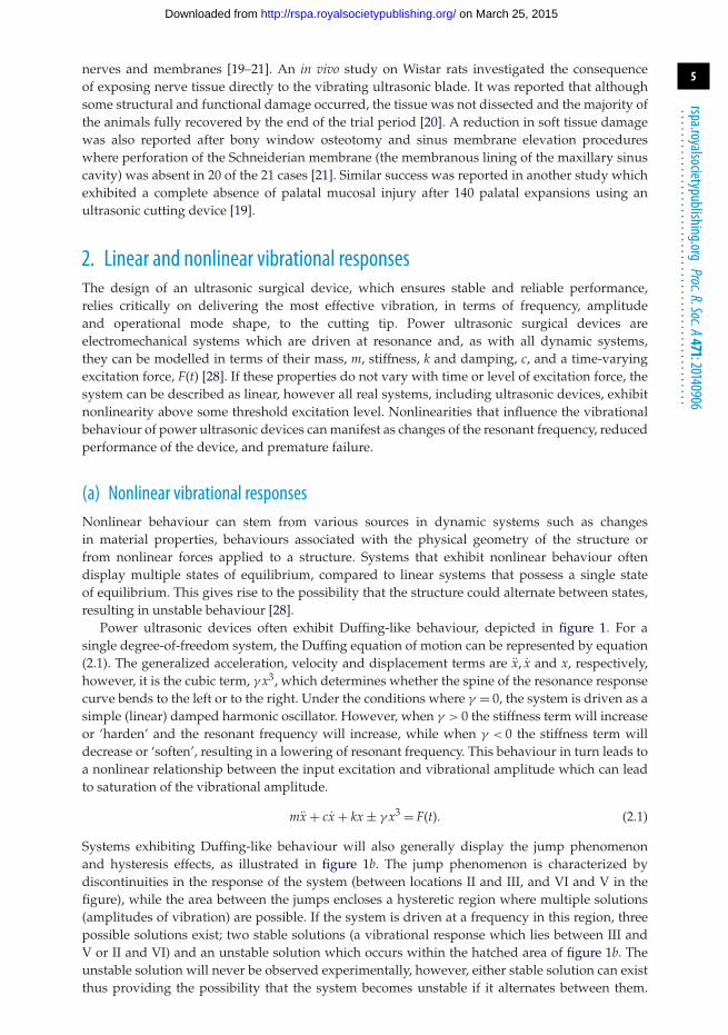
nerves and membranes [19–21]. An in vivo study on Wistar rats investigated the consequenceof exposing nerve tissue directly to the vibrating ultrasonic blade. It was reported that althoughsome structural and functional damage occurred, the tissue was not dissected and the majority ofthe animals fully recovered by the end of the trial period [20]. A reduction in soft tissue damagewas also reported after bony window osteotomy and sinus membrane elevation procedureswhere perforation of the Schneiderian membrane (the membranous lining of the maxillary sinuscavity) was absent in 20 of the 21 cases [21]. Similar success was reported in another study whichexhibited a complete absence of palatal mucosal injury after 140 palatal expansions using anultrasonic cutting device [19].
2. Linear and nonlinear vibrational responsesThe design of an ultrasonic surgical device, which ensures stable and reliable performance,relies critically on delivering the most effective vibration, in terms of frequency, amplitudeand operational mode shape, to the cutting tip. Power ultrasonic surgical devices areelectromechanical systems which are driven at resonance and, as with all dynamic systems,they can be modelled in terms of their mass, m, stiffness, k and damping, c, and a time-varyingexcitation force, F(t) [28]. If these properties do not vary with time or level of excitation force, thesystem can be described as linear, however all real systems, including ultrasonic devices, exhibitnonlinearity above some threshold excitation level. Nonlinearities that influence the vibrationalbehaviour of power ultrasonic devices can manifest as changes of the resonant frequency, reducedperformance of the device, and premature failure.
(a) Nonlinear vibrational responsesNonlinear behaviour can stem from various sources in dynamic systems such as changesin material properties, behaviours associated with the physical geometry of the structure orfrom nonlinear forces applied to a structure. Systems that exhibit nonlinear behaviour oftendisplay multiple states of equilibrium, compared to linear systems that possess a single stateof equilibrium. This gives rise to the possibility that the structure could alternate between states,resulting in unstable behaviour [28].
Power ultrasonic devices often exhibit Duffing-like behaviour, depicted in figure 1. For asingle degree-of-freedom system, the Duffing equation of motion can be represented by equation(2.1). The generalized acceleration, velocity and displacement terms are x, x and x, respectively,however, it is the cubic term, γ x3, which determines whether the spine of the resonance responsecurve bends to the left or to the right. Under the conditions where γ = 0, the system is driven as asimple (linear) damped harmonic oscillator. However, when γ > 0 the stiffness term will increaseor ‘harden’ and the resonant frequency will increase, while when γ < 0 the stiffness term willdecrease or ‘soften’, resulting in a lowering of resonant frequency. This behaviour in turn leads toa nonlinear relationship between the input excitation and vibrational amplitude which can leadto saturation of the vibrational amplitude.
mx + cx + kx ± γ x3 = F(t). (2.1)
Systems exhibiting Duffing-like behaviour will also generally display the jump phenomenonand hysteresis effects, as illustrated in figure 1b. The jump phenomenon is characterized bydiscontinuities in the response of the system (between locations II and III, and VI and V in thefigure), while the area between the jumps encloses a hysteretic region where multiple solutions(amplitudes of vibration) are possible. If the system is driven at a frequency in this region, threepossible solutions exist; two stable solutions (a vibrational response which lies between III andV or II and VI) and an unstable solution which occurs within the hatched area of figure 1b. Theunstable solution will never be observed experimentally, however, either stable solution can existthus providing the possibility that the system becomes unstable if it alternates between them.
on March 25, 2015http://rspa.royalsocietypublishing.org/Downloaded from

6
rspa.royalsocietypublishing.orgProc.R.Soc.A471:20140906
...................................................
(a)
(b)
ampl
itude
frequency
–g g = 0 +g
wn
frequency
wn
ampl
itude
III
III
IVVI
V
hysteresis region
jumpup/down
Figure 1. Duffing-like behaviour; (a) frequency response curves for varying γ : cubic softening: −γ , linear: γ = 0, cubichardening:+γ , (b) jump phenomenon and hysteretic region.
Away from this region, in regions I and IV, the response of the system is stable and hence onlyone solution exists [28].
(b) Sources of nonlinearities in ultrasonic devicesNonlinear behaviour is known to stem from a range of sources and therefore can be difficultto predict from simulations or theoretical models which do not tend to account for all possiblesources. Research has indicated that device geometry can influence nonlinear behaviour, oftenmodifying the threshold excitation level above which nonlinear responses occur [29,30]. Otherstudies have reported that material properties, such as the mechanical quality factor, Qm, ofalloys used in the manufacture of power ultrasonic devices are strain dependent above a strainthreshold consistent with the excitation levels used to drive these devices [31,32]. Furthermore,it is known that transduction materials, such as lead zirconate titanate (PZT), strongly exhibitDuffing-like responses at elevated excitation levels, leading to a loss of performance and efficiency[33–36]. Properties such as the electromechanical loss factor, keff, quality factor, Qm, and dielectricloss factor, tan δ, (all indicators of piezoceramic or transducer performance and efficiency) are
on March 25, 2015http://rspa.royalsocietypublishing.org/Downloaded from
7
rspa.royalsocietypublishing.orgProc.R.Soc.A471:20140906
...................................................
electric field strength, vibrational amplitude and temperature dependent. The elastic compliance,sE, dielectric constant, εT and piezoelectric constant, d, have also been shown to be temperatureand vibrational amplitude dependent [33–36]. The implications of all of these potential sources ofnonlinear vibrational responses on device design and performance are not well understood, andthere is a need to establish a characterization methodology in order to develop design guidelinesfor optimal operation.
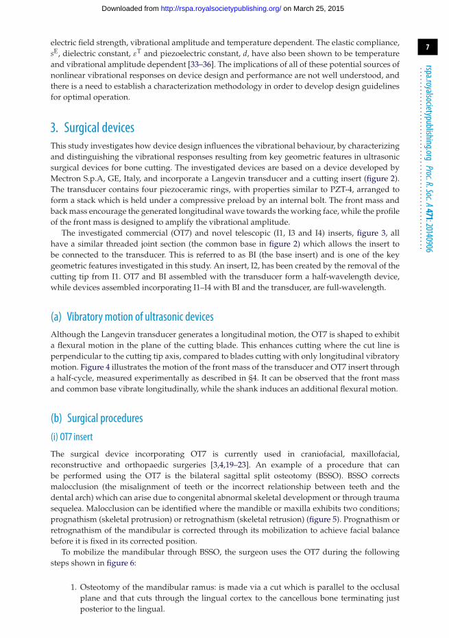
3. Surgical devicesThis study investigates how device design influences the vibrational behaviour, by characterizingand distinguishing the vibrational responses resulting from key geometric features in ultrasonicsurgical devices for bone cutting. The investigated devices are based on a device developed byMectron S.p.A, GE, Italy, and incorporate a Langevin transducer and a cutting insert (figure 2).The transducer contains four piezoceramic rings, with properties similar to PZT-4, arranged toform a stack which is held under a compressive preload by an internal bolt. The front mass andback mass encourage the generated longitudinal wave towards the working face, while the profileof the front mass is designed to amplify the vibrational amplitude.
The investigated commercial (OT7) and novel telescopic (I1, I3 and I4) inserts, figure 3, allhave a similar threaded joint section (the common base in figure 2) which allows the insert tobe connected to the transducer. This is referred to as BI (the base insert) and is one of the keygeometric features investigated in this study. An insert, I2, has been created by the removal of thecutting tip from I1. OT7 and BI assembled with the transducer form a half-wavelength device,while devices assembled incorporating I1–I4 with BI and the transducer, are full-wavelength.
(a) Vibratory motion of ultrasonic devicesAlthough the Langevin transducer generates a longitudinal motion, the OT7 is shaped to exhibita flexural motion in the plane of the cutting blade. This enhances cutting where the cut line isperpendicular to the cutting tip axis, compared to blades cutting with only longitudinal vibratorymotion. Figure 4 illustrates the motion of the front mass of the transducer and OT7 insert througha half-cycle, measured experimentally as described in §4. It can be observed that the front massand common base vibrate longitudinally, while the shank induces an additional flexural motion.
(b) Surgical procedures(i) OT7 insert
The surgical device incorporating OT7 is currently used in craniofacial, maxillofacial,reconstructive and orthopaedic surgeries [3,4,19–23]. An example of a procedure that canbe performed using the OT7 is the bilateral sagittal split osteotomy (BSSO). BSSO correctsmalocclusion (the misalignment of teeth or the incorrect relationship between teeth and thedental arch) which can arise due to congenital abnormal skeletal development or through traumasequelea. Malocclusion can be identified where the mandible or maxilla exhibits two conditions;prognathism (skeletal protrusion) or retrognathism (skeletal retrusion) (figure 5). Prognathism orretrognathism of the mandibular is corrected through its mobilization to achieve facial balancebefore it is fixed in its corrected position.
To mobilize the mandibular through BSSO, the surgeon uses the OT7 during the followingsteps shown in figure 6:
1. Osteotomy of the mandibular ramus: is made via a cut which is parallel to the occlusalplane and that cuts through the lingual cortex to the cancellous bone terminating justposterior to the lingual.
on March 25, 2015http://rspa.royalsocietypublishing.org/Downloaded from

8
rspa.royalsocietypublishing.orgProc.R.Soc.A471:20140906
...................................................
shank
cuttingblade
commonbase
piezoceramic stack
frontmass backmass
insert
bolt
transducer
Figure 2. Schematic of transducer and cutting insert.
(b)
(d )
( f )
(a)
(c)
(e)
Figure 3. Investigated inserts (a) OT7, (b) BI, (c) I1, (d) I2, (e) I3 and (f ) I4.
Figure 4. Images of deformationmeasurements (shaded and superimposed on dashed stationary image) through a half-cycleof oscillation of the OT7 insert.
on March 25, 2015http://rspa.royalsocietypublishing.org/Downloaded from

9
rspa.royalsocietypublishing.orgProc.R.Soc.A471:20140906
...................................................
ramus maxilla
angle
occlusal planemandible body
(a) (c)(b)
Figure 5. Diagrams of the skull showing (a) mandible exhibiting prognathism (b) normal mandible position (c) mandibleexhibiting retrognathism.
1
2
3
4
5
6
Figure 6. The mandibular and osteotomies during the BSSO procedure.
2. Vertical osteotomy: this cut starts from the osteotomy of step 1, cutting vertically throughthe centre of the ramus, passing through the cortex and into the cancellous bone. The cutis terminated at the second molar.
3. Mandibular body buccal osteotomy: commences at the lower border of the mandibularbody and terminates at the endpoint of the vertical osteotomy.
4. Sagittal split commencement: cancellous bone is cut up to the neurovascular bundle.5. Nerve protection: before a deeper cut to the cancellous bone of the lower border of
the mandibular is performed, the neurovascular nerve is located and protected by aseparator.
6. Completion of the Sagittal split: an osteotome is made to the mandibular body that allowsits mobilization and for its position to be corrected.
(ii) Telescopic inserts
I1, I3 and I4 have been developed for endoscopic procedures, one of which is functionalendoscopic sinus surgery (FESS). FESS is possibly the most regularly performed otolaryngology
on March 25, 2015http://rspa.royalsocietypublishing.org/Downloaded from

10
rspa.royalsocietypublishing.orgProc.R.Soc.A471:20140906
...................................................
(a)
frontal sinuses
ethmoid sinus
orbital plate ofethmoid bone
maxillary sinuses maxillary
ocular cavity
(b)
frontal sinusperpendicular plateof ethmoid bone
pituitary gland
sphenoid bone
maxilla
nasal cavity
Figure 7. The anatomy of the skull.
procedure (procedures treating disorders of the ear, nose and throat), and it is estimated thataround 300 000 are performed each year [37]. FESS is a minimally invasive procedure and surgicalsites are accessed through the nasal cavity (figure 7). FESS treats paranasal disease and restoresnormal drainage of the sinuses through clearing blockages or enlarging the nasal ostia (smallorifices that join the paranasal sinuses with the nasal cavity).
Trans-sphenoidal surgery and optic nerve decompression are procedures that could also useultrasonic devices with telescopic capability. Trans-sphenoidal surgery, a procedure that removestumours of the pituitary gland, requires access to the base of the skull through the sphenoid bonevia the nasal cavity in order to reach the pituitary gland. Decompression of the optic nerve couldalso be completed through accessing the nerve through the orbital floor from the nasal cavity.
For power ultrasonic devices to access anatomical structures in the nasal cavity region, insertsrequire to be approximately 10–15 cm in length. Straight inserts can be used in FESS proceduresthat require access to the ethmoid bone, while to access the frontal sinuses (figure 7) the cuttingtip is required to make an angle with the shaft of 50◦–70◦, as in I4. To prevent tissue damage viafrictional heating resulting from the vibrating insert, the shaft of the insert must be containedwithin a sheath.
4. Characterization of devices through experimental modal analysisThe distinctive nature of these surgical procedures results in ultrasonic device designs requiringthe incorporation of distinctive tailored features. It is therefore important to understand howvibration behaviours of both the half-wavelength and full-wavelength surgical devices areinfluenced both by their distinct and common geometric features. The basis of all the vibrationcharacterizations, for linear and nonlinear responses, is an identification of the modal frequenciesand mode shapes of each measured device configuration (as presented in figure 4). This allowsbehaviours to be associated with the tuned operational mode and/or other modal responsesof each device. Identification of modal frequencies and mode shapes is carried out through anexperimental modal analysis (EMA) [38].
For the EMA, the devices were excited with a random excitation signal, in a frequency range of0–80 kHz, by a function generator built into the data acquisition hardware (Data Physics Quattro),and amplified through a power amplifier (QSC RMX). Vibration measurements were acquired inthe form of frequency response functions (FRFs), which are a measure of the relationship betweenthe input excitation force and output vibration velocity in the Fourier domain, providing complex
on March 25, 2015http://rspa.royalsocietypublishing.org/Downloaded from

11
rspa.royalsocietypublishing.orgProc.R.Soc.A471:20140906
...................................................
(b)(a)
longitudinal node flexural node
(d)(c)
( f )(e)
longitudinal node
(i)
(i)
(i)
(ii)
(ii)
(ii)
(i)
(i)
(i)
(ii)
(ii)
(ii)
longitudinal node
longitudinal node
longitudinal node
longitudinal node
Figure8. Modesof vibrationof operational frequencies showing (i) deformedmode shape superimposedonundeformed shapeand (ii) normalized contours of deformation superimposed on undeformed shape, for (a) OT7, (b) BI, (c) I1, (d) I2, (e) I3 and (f ) I4.
functions from which magnitude and phase data can be extracted over a grid of measurementpoints. FRFs were measured from grid points located on the surface of the transducer and surgicalinserts using a three-dimensional laser Doppler vibrometer (Polytec CLV-3D) and were acquiredwith a resolution of 1.6 Hz using Signal Calc ACE data acquisition software (Data Physics).Once the FRF traces had been collected from every measurement point, they were importedto modal analysis software, ME’ScopeVES (Vibrant Technology), where a curve-fitting processgenerated a single mathematical expression which represents the vibrational responses for thewhole device from the experimental data. To visualize modes of vibration, the curve-fitted modaldata were assigned to a three-dimensional model, representing the geometry of the device, whichsubsequently could be animated through the cycles of vibration in each of the measured modes.
The mode shapes of the tuned modes of vibration measured through EMA are shown infigure 8. The contour plots, where lighter shading represents higher vibrational amplitude anddarker shading represents lower vibrational amplitudes, identify the nodal and antinodal planes.It can be observed that half-wavelength devices, containing OT7 and BI, exhibit one longitudinalnodal plane, while the full-wavelength devices, incorporating I1–I4, exhibit two. Comparison ofthe mode shapes of the half-wavelength and full-wavelength devices with and without cuttingblades illustrates how the cutting blade introduces a flexural motion to the longitudinal mode ofvibration. These modes of vibration exhibit a nodal plane associated with the flexural motionin addition to the longitudinal mode nodal plane. The location of this node is an importantconsideration, as location in a high stress region can result in failure of the insert and thereforepoor reliability of the device.
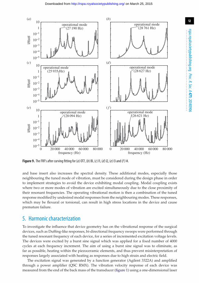
The curve-fitted FRFs, identifying the frequencies of the tuned mode of vibration of eachdevice, are shown in figure 9. The FRFs of the full-wavelength devices contain a much higherspectral density than the half-wavelength device FRFs, and this is consistent with more lowerorder flexural and torsional modes being excited at lower resonant frequencies for the full-wavelength devices. The addition of a cutting blade, or other device component, to the transducer
on March 25, 2015http://rspa.royalsocietypublishing.org/Downloaded from
12
rspa.royalsocietypublishing.orgProc.R.Soc.A471:20140906
...................................................
10−5
10−4
10−3
10−2
10−1
1
10(a)
|H(w
)|
10−5
10−4
10−3
10−2
10−1
1
10
|H(w
)|
10−5
10−4
10−3
10−2
10−1
1
10
|H(w
)|
(b)
(c) (d )
0 20 000 40 000 60 000 80 000
(e)
frequency (Hz)0 20 000 40 000 60 000 80 000
( f )
frequency (Hz)
operational mode(28 761 Hz)
operational mode(27 190 Hz)
operational mode(28 627 Hz)
operational mode(25 935 Hz)
operational mode(28 094 Hz)
operational mode(26 621 Hz)
Figure 9. The FRF’s after curving fitting for (a) OT7, (b) BI, (c) I1, (d) I2, (e) I3 and (f ) I4.
and base insert also increases the spectral density. These additional modes, especially thoseneighbouring the tuned mode of vibration, must be considered during the design phase in orderto implement strategies to avoid the device exhibiting modal coupling. Modal coupling existswhere two or more modes of vibration are excited simultaneously due to the close proximity oftheir resonant frequencies. The operating vibrational motion is then a combination of the tunedresponse modified by undesired modal responses from the neighbouring modes. These responses,which may be flexural or torsional, can result in high stress locations in the device and causepremature failure.
5. Harmonic characterizationTo investigate the influence that device geometry has on the vibrational response of the surgicaldevices, such as Duffing-like responses, bi-directional frequency sweeps were performed throughthe tuned resonant frequency of each device, for a series of incremented excitation voltage levels.The devices were excited by a burst sine signal which was applied for a fixed number of 4000cycles at each frequency increment. The aim of using a burst sine signal was to eliminate, asfar as possible, heating within the piezoceramic elements, and thus prevent misinterpretation ofresponses largely associated with heating as responses due to high strain and electric field.
The excitation signal was generated by a function generator (Agilent 3322A) and amplifiedthrough a power amplifier (QSC RMX). The vibration velocity response of each device wasmeasured from the end of the back mass of the transducer (figure 1) using a one-dimensional laser
on March 25, 2015http://rspa.royalsocietypublishing.org/Downloaded from
13
rspa.royalsocietypublishing.orgProc.R.Soc.A471:20140906
...................................................
27 800 27 900 28 000 28 1000
10
20
30
40(a)
frequency (Hz)
tem
pera
ture
(°C
)
26 900 27 000 27 100 27 200
(b)
frequency (Hz)
2 Vr.m.s.
6 Vr.m.s.
10 Vr.m.s.
15 Vr.m.s.
20 Vr.m.s.
25 Vr.m.s.
30 Vr.m.s.
35 Vr.m.s.
40 Vr.m.s.
45 Vr.m.s.
50 Vr.m.s.
sweep down
sweep up
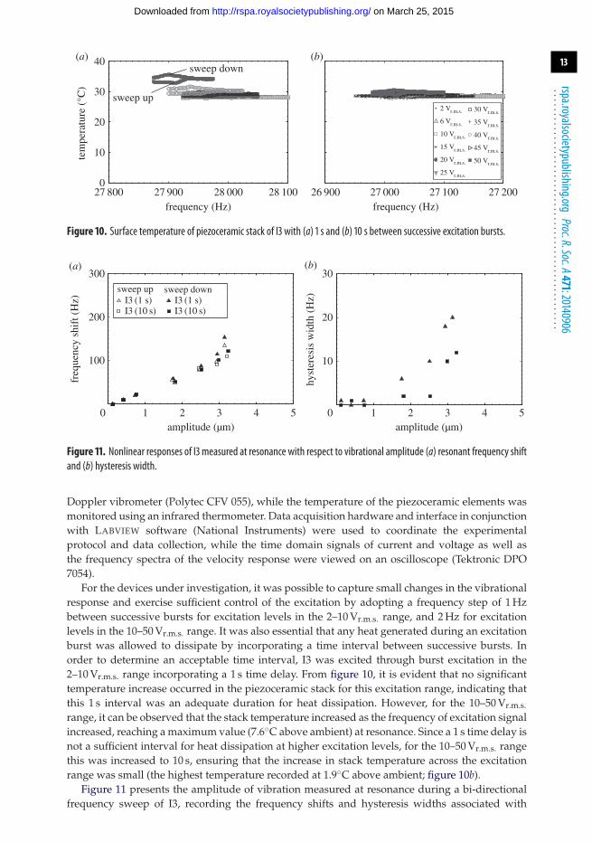
Figure 10. Surface temperature of piezoceramic stack of I3 with (a) 1 s and (b) 10 s between successive excitation bursts.
0 1 2 3 4 5
100
200
300(a)
amplitude (µm)
freq
uenc
y sh
ift (
Hz) I3 (1 s)
I3 (10 s)I3 (1 s)I3 (10 s)
0 1 2 3 4 5
10
20
30(b)
amplitude (µm)
hyst
eres
is w
idth
(H
z)
sweep up sweep down
Figure 11. Nonlinear responses of I3 measured at resonance with respect to vibrational amplitude (a) resonant frequency shiftand (b) hysteresis width.
Doppler vibrometer (Polytec CFV 055), while the temperature of the piezoceramic elements wasmonitored using an infrared thermometer. Data acquisition hardware and interface in conjunctionwith LABVIEW software (National Instruments) were used to coordinate the experimentalprotocol and data collection, while the time domain signals of current and voltage as well asthe frequency spectra of the velocity response were viewed on an oscilloscope (Tektronic DPO7054).
For the devices under investigation, it was possible to capture small changes in the vibrationalresponse and exercise sufficient control of the excitation by adopting a frequency step of 1 Hzbetween successive bursts for excitation levels in the 2–10 Vr.m.s. range, and 2 Hz for excitationlevels in the 10–50 Vr.m.s. range. It was also essential that any heat generated during an excitationburst was allowed to dissipate by incorporating a time interval between successive bursts. Inorder to determine an acceptable time interval, I3 was excited through burst excitation in the2–10 Vr.m.s. range incorporating a 1 s time delay. From figure 10, it is evident that no significanttemperature increase occurred in the piezoceramic stack for this excitation range, indicating thatthis 1 s interval was an adequate duration for heat dissipation. However, for the 10–50 Vr.m.s.
range, it can be observed that the stack temperature increased as the frequency of excitation signalincreased, reaching a maximum value (7.6◦C above ambient) at resonance. Since a 1 s time delay isnot a sufficient interval for heat dissipation at higher excitation levels, for the 10–50 Vr.m.s. rangethis was increased to 10 s, ensuring that the increase in stack temperature across the excitationrange was small (the highest temperature recorded at 1.9◦C above ambient; figure 10b).
Figure 11 presents the amplitude of vibration measured at resonance during a bi-directionalfrequency sweep of I3, recording the frequency shifts and hysteresis widths associated with
on March 25, 2015http://rspa.royalsocietypublishing.org/Downloaded from
14
rspa.royalsocietypublishing.orgProc.R.Soc.A471:20140906
...................................................
26 700 26 800 26 900 27 000 27 1000
1
2
3
4
5(a)
ampl
itude
(mm
)
0
1
2
3
4
5
ampl
itude
(mm
)
0
1
2
3
4
5
ampl
itude
(mm
)
28 400 28 500 28 600 28 700 28 800
(b)
26 000 26 100 26 200 26 300 26 400
(c)
28 300 28 400 28 500 28 600 28 700
(d )
27 800 27 900 28 000 28 100 28 200
(e)
frequency (Hz)26 900 27 000 27 100 27 200 27 300
( f )
frequency (Hz)
2 Vr.m.s. 6 Vr.m.s. 10 Vr.m.s. 15 Vr.m.s. 20 Vr.m.s. 25 Vr.m.s.
30 Vr.m.s. 35 Vr.m.s. 40 Vr.m.s. 45 Vr.m.s. 50 Vr.m.s.
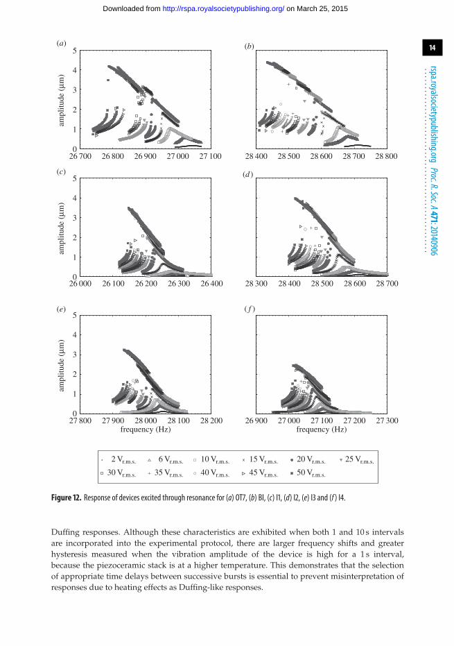
Figure 12. Response of devices excited through resonance for (a) OT7, (b) BI, (c) I1, (d) I2, (e) I3 and (f ) I4.
Duffing responses. Although these characteristics are exhibited when both 1 and 10 s intervalsare incorporated into the experimental protocol, there are larger frequency shifts and greaterhysteresis measured when the vibration amplitude of the device is high for a 1 s interval,because the piezoceramic stack is at a higher temperature. This demonstrates that the selectionof appropriate time delays between successive bursts is essential to prevent misinterpretation ofresponses due to heating effects as Duffing-like responses.
on March 25, 2015http://rspa.royalsocietypublishing.org/Downloaded from

15
rspa.royalsocietypublishing.orgProc.R.Soc.A471:20140906
...................................................
0 1 2 3 4 5
100
200
300(a)
amplitude (µm)
freq
uenc
y sh
ift (
Hz)
0 1 2 3 4 5
10
20
30(b)
amplitude (µm)
hyst
eres
is w
idth
(H
z)
OT7BII1I2I3I4
OT7BII1I2I3I4
sweep up sweep down OT7BII1I2I3I4
Figure 13. Nonlinear responses of devices with respect to vibrational amplitude for (a) resonant frequency shift and (b) widthof hysteresis region.
Table 1. Selected data from figure 12, illustrative of the comparative Duffing-like behaviour exhibited by the devices.
measured at 2.5µm jump first observed at:
resonant frequency width of hysteresis
shift (Hz) region (Hz) amplitude (µm) voltage (Vr.m.s.)
OT7 121 12 1.81 15. . . . . . . . . . . . . . . . . . . . . . . . . . . . . . . . . . . . . . . . . . . . . . . . . . . . . . . . . . . . . . . . . . . . . . . . . . . . . . . . . . . . . . . . . . . . . . . . . . . . . . . . . . . . . . . . . . . . . . . . . . . . . . . . . . . . . . . . . . . . . . . . . . . . . . . . . . . . . . . . . . . . . . . . . . . . . . . . . . . . . . . . . . . . . . . . . . . . . . . . . .
BI 133 8 1.81 15. . . . . . . . . . . . . . . . . . . . . . . . . . . . . . . . . . . . . . . . . . . . . . . . . . . . . . . . . . . . . . . . . . . . . . . . . . . . . . . . . . . . . . . . . . . . . . . . . . . . . . . . . . . . . . . . . . . . . . . . . . . . . . . . . . . . . . . . . . . . . . . . . . . . . . . . . . . . . . . . . . . . . . . . . . . . . . . . . . . . . . . . . . . . . . . . . . . . . . . . . .
I1 120 6 1.97 25. . . . . . . . . . . . . . . . . . . . . . . . . . . . . . . . . . . . . . . . . . . . . . . . . . . . . . . . . . . . . . . . . . . . . . . . . . . . . . . . . . . . . . . . . . . . . . . . . . . . . . . . . . . . . . . . . . . . . . . . . . . . . . . . . . . . . . . . . . . . . . . . . . . . . . . . . . . . . . . . . . . . . . . . . . . . . . . . . . . . . . . . . . . . . . . . . . . . . . . . . .
I2 113 10 2.47 25. . . . . . . . . . . . . . . . . . . . . . . . . . . . . . . . . . . . . . . . . . . . . . . . . . . . . . . . . . . . . . . . . . . . . . . . . . . . . . . . . . . . . . . . . . . . . . . . . . . . . . . . . . . . . . . . . . . . . . . . . . . . . . . . . . . . . . . . . . . . . . . . . . . . . . . . . . . . . . . . . . . . . . . . . . . . . . . . . . . . . . . . . . . . . . . . . . . . . . . . . .
I3 80 2 1.26 15. . . . . . . . . . . . . . . . . . . . . . . . . . . . . . . . . . . . . . . . . . . . . . . . . . . . . . . . . . . . . . . . . . . . . . . . . . . . . . . . . . . . . . . . . . . . . . . . . . . . . . . . . . . . . . . . . . . . . . . . . . . . . . . . . . . . . . . . . . . . . . . . . . . . . . . . . . . . . . . . . . . . . . . . . . . . . . . . . . . . . . . . . . . . . . . . . . . . . . . . . .
I4 105 8 1.60 25. . . . . . . . . . . . . . . . . . . . . . . . . . . . . . . . . . . . . . . . . . . . . . . . . . . . . . . . . . . . . . . . . . . . . . . . . . . . . . . . . . . . . . . . . . . . . . . . . . . . . . . . . . . . . . . . . . . . . . . . . . . . . . . . . . . . . . . . . . . . . . . . . . . . . . . . . . . . . . . . . . . . . . . . . . . . . . . . . . . . . . . . . . . . . . . . . . . . . . . . . .
(a) Insert effect on vibrational responseThe vibrational responses of the devices excited through resonance are presented in figure 12,and it can be observed that all the devices exhibit Duffing-like behaviour. Resonant frequencyshifts and amplitude jumps can be seen in all measurements, the curvature of the spine of all theresponse curves being consistent with stiffness softening. In order to compare these behavioursfor the different devices, the frequency shifts and widths of hysteresis regions were extracted fromthe data in figure 12.
Figure 13a illustrates that for all devices, the larger the amplitude of vibration the largerthe resonant frequency shift. However, it can also be seen from figure 13a and table 1 that atelevated amplitudes of vibration the half-wavelength devices (OT7and BI) exhibit larger resonantfrequency shifts than the full-wavelength devices (I1–I4). This is consistent with a previous study,of ultrasonic food-cutting devices, that reported larger frequency shifts with increasing excitationlevel for longer devices [39]. It is known that the Qm of alloys commonly used to manufactureultrasonic devices, particularly TiV6Al4 and 300 series stainless steel, drops off rapidly once avibrational amplitude threshold has been reached. Qm is a measure of damping and hence it canbe expected that a lowering of Qm will result in a lowering of resonant frequency [31,32].
Although all the devices displayed the jump phenomenon and hysteresis, as observed infigure 12, a definite relationship does not appear to exist with the device geometry, including thepresence of a flexural as well as axial vibrational motion. Figure 13a illustrates that the widths of
on March 25, 2015http://rspa.royalsocietypublishing.org/Downloaded from

16
rspa.royalsocietypublishing.orgProc.R.Soc.A471:20140906
...................................................
(a)
ampl
itude
(m
ms–1
)
(b)
(c)
ampl
itude
(m
ms–1
) am
plitu
de (
mm
s–1)
(d)
0 20 000 40 000 60 000 80 000 100 000
(e)
frequency (Hz)0 20 000 40 000 60 000 80 000 100 000
( f )
frequency (Hz)
w2
10−1
102
103
W
WW
W
w1w1w2
w2
W W
w1
w1
w2
1
10
10−1
102
103
1
10
10−1
102
103
1
10
w2
w1
w2w1
Figure 14. Power spectra of devices excited close to resonance at 50 Vr.m.s. (a) OT7, (b) BI, (c) I1, (d) I2, (e) I3 and (f ) I4.
the hysteresis regions are small, if not insignificant, below a vibrational threshold (around 1.8 µmfor these devices). Above this threshold, the hysteresis widths all increase with excitation level.Meanwhile, the excitation level at which the jump phenomenon is first observed is presented intable 1, where it can be seen that, again, no relationship is emerging relating the geometry of thedevice to the excitation threshold.
Duffing-like behaviour is known to stem from several sources in power ultrasonic devices and,although the devices exhibited differing levels of cubic softening, these have been accredited tononlinear material properties of the inserts induced by elevated strain levels. However, Duffing-like behaviour can also be induced in power ultrasonic devices through sub-optimal tighteningof threaded joints and from non-constant piezoceramic properties [33–35,40–42]. It is known thatpiezoceramic materials exhibit an increase in their elastic compliance, sE
11, under elevated stress,which has the effect of lowering the resonant frequency and resulting in the jump phenomenon[35]. This is exacerbated when the piezoceramic material is exposed to higher temperatures. Highstress and elevated temperatures have also shown to increase both the mechanical and dielectriclosses [34,41] and these losses, specifically the dielectric losses, have also been suggested as thecause of Duffing-like behaviour in piezoceramic-based devices [41].
on March 25, 2015http://rspa.royalsocietypublishing.org/Downloaded from

17
rspa.royalsocietypublishing.orgProc.R.Soc.A471:20140906
...................................................
(b) Harmonic responsesThe power spectra of the devices when excited at 50 Vr.m.s. close to their resonant frequency arepresented in figure 14. It can be observed that the spectral responses of BI and I2 are similar,while OT7, I1 and I3 show similarities. The excitation frequency, Ω , as well as the first and secondharmonics, ω1, and ω2, are visible in the power spectra of BI and I2. However, responses in thespectra of OT7, I1 and I3 other than ω1 and ω2, and with a frequency relationship of ωk = k0.5Ω
(where k is the harmonic number) can also be observed.These responses can be accredited to the presence of the flexural motion induced by the cutting
blade in OT7, I1 and I3, but also indicate a system exhibiting period-2 motion. Period-2 motion isthe first step of the period doubling route to chaotic behaviour, which if reached would result inunpredictable and uncontrollable behaviour in the devices [28]. Period-2 motion will only occurabove an excitation threshold and from the power spectra it is clear that this threshold has beenexceeded for OT7, I1 and I3. The spectral response of I4 appears to indicate that the device is closeto the threshold of period-2 motion, and if the excitation level was higher, then I4 would alsoexhibit this route to chaos.
6. ConclusionAlthough power ultrasonic surgical devices have been routinely adopted to cut hard tissue forover a decade, their use in surgery is still limited when compared with the more conventionalmechanical or pneumatic-powered devices. To enable the wider adoption of power ultrasonicdevices, a better understanding of the design of stable, effective and efficient devices is required.
This investigation illustrates the influence that device geometry has on some nonlinearbehaviours, while having a limited effect on others. Certain behaviours were observed to beinfluenced by device length; at higher vibrational amplitudes longer devices (full-wavelength)were found to exhibit smaller shifts in resonant frequency than shorter devices (half-wavelength).However, the device length or the presence of geometric features, such as a cutting blade, hadlimited influence on the formation of hysteretic regions and the jump phenomenon. Nevertheless,all the Duffing-like behaviours were influenced by piezoceramic stack temperature and thereforeone effective method of reducing the adverse effects of nonlinear responses in power ultrasonicdevices is through the careful control of the stack temperature.
As expected, longer devices exhibited higher modal density than the shorter devices withinthe frequency range of the investigation. However, incorporating an off-axis geometric feature,such as a curved insert, further increased the number of modes of vibration identified throughEMA. This increases the possibility of modal coupling occurring between the tuned mode anda neighbouring mode of vibration. Modal coupling can be minimized by ensuring there is asufficient frequency separation between the operational mode and its neighbouring modes ofvibration. However, incorporating an off-axis geometrical feature also resulted in a spectralresponse exhibiting the period doubling route to chaos. While chaotic behaviour was notobserved in this study, the presence of period doubling implies that these devices, especially thosewith features that lie outside their axis, should be monitored to ensure that chaotic behaviourdoes not manifest in the device during operation. The future is likely to see a significant increasein power ultrasonic devices used in surgical procedures, especially longer more slender devicesfor endoscopic procedures and higher power devices capable of cutting through large bones. Forboth, it becomes more likely that the vibrational threshold at which chaotic behaviour manifestsis reached under operating conditions. The nonlinear response characterizations reported herewill need to become a routine part of the design process if reliable novel power ultrasonic devicesexhibiting stable behaviour are to be realized.
Data accessibility. The datasets supporting this article have been uploaded as part of the electronic supplementarymaterial.Acknowledgements. The authors are grateful to the Power Ultrasonics Group of the Consejo Superior de lasInvestigaciones Cientificas (CSIC), Madrid, for access to laboratory facilities and to Peter McKenna (University
on March 25, 2015http://rspa.royalsocietypublishing.org/Downloaded from

18
rspa.royalsocietypublishing.orgProc.R.Soc.A471:20140906
...................................................
of Glasgow) for assistance with producing the graphics for many of the figures. A.M. and M.L. are employedby the University of Glasgow; N.C. is an employee of Mectron S.p.A; A.C. was an employee of the Universityof Glasgow when this study was initiated and is now an employee of Pusonics SL.Author contributions. A.M. was primarily responsible for carrying out the experiments and wrote the first draftof the article; A.C. conceived the initial study and was responsible for developing the experimental protocols;N.C. participated in the design of the components that are characterized in the study and provided expertisein the analysis; M.L. led the research in nonlinear characterization of ultrasonic surgical devices, participatedin the design of the study and helped draft the manuscript.Funding statement. This work has been funded by the Engineering and Physical Sciences Research Council(EPSRC) grant no. EP/E025811/1 with Mectron S.p.A, Carasco, Genoa, as project partner.Competing interests. We declare that we have no competing interests.
References1. Neppiras E. 1972 Macrosonics in industry 1: introduction. Ultrasonics 10, 9–13. (doi:10.1016/
0041-624X(72)90207-7)2. Lucas M, Gachagan A, Cardoni A. 2009 Research applications and opportunities in
power ultrasonics. Proc. IMechE Part C: J. Mech. Eng. Sci. 223, 2949–2965. (doi:10.1243/09544062JMES1671)
3. Labanca M, Azzola F, Vinci R, Rodella L. 2008 Piezoelectric surgery: twenty years of use. Br. J.Oral Maxillofac. Surg. 46, 265–269. (doi:10.1016/j.bjoms.2007.12.007)
4. O’Daly B, Morris E, Gavin G, O’Byrne J, McGuinness G. 2008 High-power low-frequencyultrasound: a review of tissue dissection and ablation in medicine and surgery. J. Mater.Process. Technol. 200, 38–58. (doi:10.1016/j.jmatprotec.2007.11.041)
5. Catuna M. 1953 Sonic energy: a possible dental application. Ann. Density 12, 100–101.6. Postle H. 1958 Ultrasonic cavity preparation. J. Prosthet. Dent. 8, 153–160. (doi:10.1016/
0022-3913(58)90027-1)7. Zinner D. 1955 Recent ultrasonic dental studies including periodontia, without the use of an
abrasive. J. Dent. Res. 34, 748–749.8. Suppipat N. 1974 Ultrasonics in periodontics. J. Clin. Periodontol. 1, 206–213.
(doi:10.1111/j.1600-051X.1974.tb01259.x)9. Trenter S, Walmsley A, Landini G, Shippen J. 2002 Assessment of the ultrasonic dental scaler
insert. Med. Eng. Phys. 24, 139–144. (doi:10.1016/S1350-4533(01)00103-5)10. Martin H. 1976 Ultrasonic disinfection of the root canal. Oral Surg. Oral Med. Oral. Pathol. 42,
92–99. (doi:10.1016/0030-4220(76)90035-9)11. Walmsley A, Laird W, Lumley P. 1992 Ultrasound in dentistry. Part 2- periodontology and
endodontics. J. Dent. 20, 11–17. (doi:10.1016/0300-5712(92)90003-U)12. Vang A. 1955 Vibratory surgical instruments. US Patent 2714890.13. Mararow H. 1960 Bone repair after experimentally produced defects. J. Oral Surg. Anesth.
Hosp. Dent. Serv. 18, 107–114.14. McFall T, Yamane G, Burnett G. 1961 Comparison of the cutting effect on bone of an ultrasonic
cutting device and rotary burs. J. Oral Surg. Anesth. Hosp. Dent. Serv. 19, 200–209.15. Volkov M, Shepeleva I. 1974 The use of ultrasonic instrumentation for the transection and
uniting of bone tissue in orthopaedic surgery. Reconstr. Surg. Traumat. 14, 147–152.16. Horton J, Tarpley T, Wood L. 1975 The healing of surgical defects in alveolar bone produced
with ultrasonic instrumentation, chisel, and rotary bur. Oral Surg. Oral Med. Oral Pathol. 39,536–546. (doi:10.1016/0030-4220(75)90192-9)
17. Horton J, Tarpley T, Wood L. 1981 Clinical applications of ultrasonic instrumentation inthe surgical removal of bone. Oral Surg. Oral Med. Oral Pathol. 51, 236–242. (doi:10.1016/0030-4220(81)90051-7)
18. Aro H, Kallioniemi H, Aho A, Kellokumpu-Lehtinen P. 1982 Ultrasonic device in bonecutting: a histological and scanning electron microscopical study. Acta Orthop. Scand. 52, 5–10.(doi:10.3109/17453678108991750)
19. Beziat J-L, Bera J-C, Lavandier B, Gleizal A. 2007 Ultrasonic osteotomy as a new techniquein craniomaxillofacial surgery. Int. J. Oral Maxillofac. Surg. 36, 493–500. (doi:10.1016/j.ijom.2007.01.012)
20. Schaeren S, Jaquiéry C, Heberer M, Tolnay M, Vercellotti T, Martin I. 2008 Assessment of nervedamage using a novel ultrasonic device for bone cutting. J. Oral Maxillofac. Surg. 66, 593–596.(doi:10.1016/j.joms.2007.03.025)
on March 25, 2015http://rspa.royalsocietypublishing.org/Downloaded from

19
rspa.royalsocietypublishing.orgProc.R.Soc.A471:20140906
...................................................
21. Vercellotti T, De Paoli S, Nevins M. 2001 The piezoelectric bony window osteotomy andsinus membrane elevation: introduction of a new technique for simplification of the sinusaugmentation procedure. Int. J. Periodontics Restorative Dent. 21, 561–567.
22. Preti G, Martinasso G, Peirone B, Navone R, Manzella C, Muzio G, Russo C, Canuto R,Schierano G. 2007 Cytokines and growth factors involved in the osseointegration of oraltitanium implants positioned using piezoelectric bone surgery versus a drill technique: a pilotstudy in minipigs. J. Periodontol. 78, 716–722. (doi:10.1902/jop.2007.060285)
23. Blus C, Szmukler-Moncler S, Vozza I, Rispoli L, Polastri C. 2010 Split-crest and immediateimplant placement with ultrasonic bone surgery (piezosurgery): 3-year follow-up of 180treated implant sites. Quintessence Int. 41, 463–469.
24. Dolan E, Haugh M, Tallon D, Casey C, McNamara L. 2012 Heat-shock-induced cellularresponses to temperature elevations occurring during orthopaedic cutting. J. R. Soc. Interface9, 3503–3513. (doi:10.1098/rsif.2012.0520)
25. Lucas M, Cardoni A, MacBeath A. 2005 Temperature effects in ultrasonic cutting of naturalMaterials. CIRP Ann.Manuf. Technol. 54, 195–198. (doi:10.1016/S0007-8506(07)60082-1)
26. Cardoni A, MacBeath A, Lucas M. 2006 Methods for reducing cutting temperature inultrasonic cutting of bone. Ultrasonics 44, e37–e42. (doi:10.1016/j.ultras.2006.06.046)
27. Khambay B, Walmsley A. 2000 Investigations into the use of an ultrasonic chisel to cut bone.Part 1: forces applied by clinicians. J. Dent. 28, 31–37. (doi:10.1016/S0300-5712(99)00043-3)
28. Thomsen JJ. 1997 Vibrations and stability: order and chaos. London, UK: McGraw-Hill.29. Mathieson A, Cardoni A, Cerisola N, Lucas M. 2013 The influence of piezoceramic stack
location on nonlinear behavior of Langevin transducers. IEEE Trans. Ultras. Ferro. Freq. Cont.60, 1126–1133. (doi:10.1109/TUFFC.2013.2675)
30. Lim F, Cartmell M, Cardoni A, Lucas M. 2004 A preliminary investigation into optimisingthe response of vibrating systems used for ultrasonic cutting. J. Sound Vib. 272, 1047–1069.(doi:10.1016/j.jsv.2003.03.011)
31. Puškár A. 1982 Cyclic stress-strain curves and internal friction of steel at ultrasonicfrequencies. Ultrasonics 20, 118–122. (doi:10.1016/0041-624X(82)90072-5)
32. Campos-Pozuelo C, Gallego-Juarez J. 1996 Limiting strain of metals subjected to high-intensity ultrasound. Acta Acust. 82, 823–828.
33. Aurelle N, Guyomar D, Richard C, Gonnard P, Eyraud L. 1996 Nonlinear behavior of anultrasonic transducer. Ultrasonics 34, 187–191. (doi:10.1016/0041-624X(95)00077-G)
34. Umeda M, Nakamura K, Ueha S. 1999 Effects of vibration stress and temperature on thecharacteristics of piezoelectric ceramics under high vibration amplitude levels measured byelectrical transient method. Jpn. J. Appl. Phys. 38, 5581–5585. (doi:10.1143/JJAP.38.5581)
35. Umeda M, Nakamura K, Takahashi S, Ueha S. 2000 An analysis of jumping and droppingphenomena of piezoelectric transducers using the electrical equivalent circuit constants athigh vibration amplitude levels. Jpn. J. Appl. Phys. 39, 5623–5628. (doi:10.1143/JJAP.39.5623)
36. Albareda A, Perez R, Casals J, Garcia J, Ochoa D. 2007 Optimization of elastic nonlinearbehavior measurements of ceramic piezoelectric resonators with burst excitation. IEEE Trans.Ultras. Ferro. Freq. Cont. 54, 2175–2188. (doi:10.1109/TUFFC.2007.514)
37. Sillers M, Lay K. 2006 Principles of revision functional endoscopic sinus surgery. Oper. Tech.Otolaryngol. Head Neck. Surg. 17, 6–12. (doi:10.1016/j.otot.2005.12.005)
38. Ewins DJ. 2000 Modal testing—theory, practice and application, 2nd edn. Baldock, Hertfordshire,UK: Research Studies Press.
39. Cardoni A. 2003 Characterising the dynamic response of ultrasonic cutting devices. PhD,Department of Mechanical Engineering, University of Glasgow, UK.
40. Albareda A, Gonnard P, Perrin V, Briot R, Guyomar D. 2000 Characterization of themechanical nonlinear behavior of piezoelectric ceramics. IEEE Trans. Ultras. Ferro. Freq. Cont.47, 844–853. (doi:10.1109/58.852066)
41. Guymar D, Ducharne B, Sebald G. 2011 High nonlinearities in Langevin transducer: acomprehensive model. Ultrasonics 51, 1006–1013. (doi:10.1016/j.ultras.2011.05.017)
42. Riviere J, Renaud G, Haupert S, Talmant M, Laugier P, Johnson P. 2010 Nonlinear acousticresonances to probe a threaded interface. J. Appl. Phys. 107, 124901. (doi:10.1063/1.3443578)
on March 25, 2015http://rspa.royalsocietypublishing.org/Downloaded from