mathematical modeling of performance of a liqud piston...
TRANSCRIPT
9. Pompa Vana Kompressor Kongresi
5-7 Mayıs 2016, Istanbul
MATHEMATICAL MODELING OF PERFORMANCE OF A LIQUD PISTONCOMPRESSOR
Suleyman Dogan OnerDepartment of Mechanical Engineering
I.D. Bilkent UniversityEmail: [email protected]
Ibrahim Nasuh YıldıranDepartment of Mechanical Engineering
I.D. Bilkent UniversityEmail: [email protected]
Okan Deniz YılmazDepartment of Mechanical Engineering
I.D. Bilkent UniversityEmail: [email protected]
Barbaros CetinDepartment of Mechanical Engineering
Associate ProfessorI.D. Bilkent University
Email: [email protected]
ABSTRACT
The compressed air produced by compressors has been us-ing in many different industries, and the efficiency of a com-pressor is important regarding the both the economical and envi-ronmental aspects. In a conventional compressor, a solid pistoncompresses the air. During this compression process, an air leakoccurs which diminishes the performance of a compressor. Theleakage becomes even greater as the operation time increases.Moreover, the compression process of the solid piston performedat a relatively high speed (several hundred rpms) to minimize theair leakage. Since the gas does not have enough time to haveenough heat transfer, compression at high speed increases in thegas temperature, which leads to an inefficient compression pro-cess. One alternative to overcome this issue is to use liquid pis-ton in which the solid piston is replaced by the liquid rising in acolumn. This way, both the air leakage can be avoided and thecompression process can be performed slower. Moreover, due tothe circulating nature of the water, and the superior heat trans-fer characteristic of the flowing water, a better heat transfer cantake place which leads to a lower temperature rise of the gas, andhence more efficient compression process. With a more efficientcompression process, the environmental foot print of the processcan be minimized. In this study, a mathematical model to pre-dict the performance of a liquid piston is developed. The liquid
piston considered in this study includes also small metal tubingsinside the main cylinder to enhance the heat transfer between theliquid and the compressed gas. The performance of the liquidpiston compression is presented as a function of number of tubespacked in the main cylinder.
NOMENCLATURE
m mass (kg)A heat transfer area (m2)Ac cross-sectional area (m2)C Sutherland constant (120 K)h convective heat transfer coefficientk thermal conductivity of the gas (W/m·K)Cv specific heat capacity (kJ/kgK)L axial extent of heated region (m)Nu Nusselt number, hLchar/kRe Reynolds number, V Lchar/µ
p Pressure (Pa)P Wetted perimeter (m)Pr Prandtl number, µ/α
∀ volume of the gas (m3)
t tube wall thickness (m)Di inner tube diameter (m)Do outer tube diameter (m)Dpc outer diameter of the cylinder (m)T temperature (K)Tw wall temperature (K)To reference temperature (K)U internal energy (kJ)V Average velocity (m/s)f friction factorWf frictional work (J)W compression work (J)E stored energy (J)
Greekν kinematic viscosityρ densityµo reference dynamic viscosityη efficiencyηcomp compression efficiencyε surface roughness
Subscriptc.v. control volumeg Gas
INTRODUCTIONPressurized air is commonly used in industry. Compressors
with reciprocating pistons are preferred to increase pressure ofair. These compressors are using mechanical power to movethe metal piston in a cylinder in which the pressure of air is in-creased. At the end of compression process, the air is deliveredto a storage tank through valves. Then, another valve is openedto suck atmospheric air in to the cylinder. This cycle runs overand over again till the filling of storage tank with air at desiredpressure. During the compression process, an air leak occurs. Tominimize the amount of air leak, the compression process shouldbe performed at a relatively high speed (typically several hundredrpms). Although increased piston velocity prevents gas leakageup to some extent, it also restricts the amount of heat transferfrom the pressurized gas to the environment. Hence, temperatureof air is increased. This situation hinders to obtain pressurizedair with high efficiency, because some amount of work deliveredby the motor is used to increase temperature of the gas [1]. In ad-dition to this, when air is cooled to room temperature in storagetank, its pressure decreases significantly.
As an alternative technology, the replacement of the solidpiston with a liquid piston has been suggested [2]. In a liquidpiston compressor, water, oil or some another appropriate liquidcan be pumped into a cylinder to pressurize the air. When desiredpressure is maintained, the check valve let the air be transferredto storage tank. There are major improvements coming with liq-
uid piston compressor. The most significant advantage of thisnew concept is to prevent gas leakage inherently by the nature ofthe liquid [3]. Since the air is not allowed to leak, the cycle canbe operated slower then conventional compressors which allowsthe heat transfer to take place which will decrease the tempera-ture rise during the compression process. Hence, the efficiencyof compressor is increased by using the power delivered by thepump almost only to increase the pressure of air. Moreover, in-clusion of some metal inserts can further enhance the heat trans-fer between the pressurized air and the water, hence the efficiencyof the compression process [4]. Therefore, liquid piston com-pressors serves as a more environmentally friendly alternativecompared to conventional compressors by supplying the sameamount of air with desired pressure with a less power.
In this study, a mathematical model to predict the perfor-mance of a liquid piston is developed. The liquid piston con-sidered in this study includes also small metal tubings inside themain cylinder to enhance the heat transfer between the liquid andthe compressed gas. The performance of the liquid piston com-pression is presented as a function of number of tubes packedin the main cylinder. The polytropic constant, compression effi-ciency, total efficiency and the total work per stroke of the com-pression process is determined as a function of number of tubesinserted in the main cylinder.
THEORYTaking the control volume as the gas inside the cylinder (see
Figure ), by neglecting kinetic and potential energies, first law ofthermodynamics reads as:
dUc.v.
dt= Q−W (1)
The term on left hand side can be written as:
dUc.v.
dt=CvTg
dmc.v.
dt+mc.v.Cv
dTg
dt(2)
where T is the temperature of the gas inside the cylinder at timet. The stroke of a piston composed of two phases. In Phase-I,only the compression process takes with a closed valve. Whenthe desired critical pressure (Pc) is reached the value opens andthe compressed gas is transferred out of the cylinder at constantpressure, Pc (Phase-II). The rate of change of the mass inside thecontrol volume can be written as:
dmc.v.
dt=
0 t < tc (Phase-I)
ρAcx− Pc
RgT 2g
dTg
dt, t > tc (Phase-II)
(3)

Water
Tg(t)
Pg(t)
8(t)
Tg(t)
Pg(t)
8(t)
Water
Tg(t + �t)
Pg(t + �t)
8(t + �t)
Time = t + �tTime = t
Valve
Controlvolume
x(t)
Ho
FIGURE 1. Schematics of the cylinder with metal tubes
where tc is the time when the critical value is reached.The first term on the right hand side of Eq. 1 indicates that
convective heat transfer between the gas and solid walls whichare assumed to be kept at constant temperature of T∞ (neglectingheat transfer occurring the at the interface of the water and thegas):
Qconv = hA(T −Ts) (4)
To estimate the heat transfer coefficient, the gas flow within thecylinder can be modeled as a fully-developed pipe flow, and theNusselt number can determined as [1]:
Nu =hLchar
k= aRemPrn (5)
where a, m and n are constant which depend on the flow regime.Within the operational temperature range of the process, thethermo-pyhsical properties of the gas is temperature dependent.However, considering only the kinematic viscosity as a functionof temperature following Sutherland’s law
ν =µ0
ρ
T0 +CT +C
(TTo
)3/2
(6)
the heat transfer coefficient can be determined by the followingconstants with Pr = 0.7 [1]:
a = 0.664, m = 1/2, n = 1/3 laminar flow (Re < 2300)a = 0.023, m = 0.8, n = 0.3 turbulent flow (Re > 2300)
The second term on the right hand side of Eq. 1 describes therate of work done on the control volume and can be calculatedas:
W = Pgd∀dt
(7)
Moreover, the temperature, pressure and the density of thegas is related to each other through the Ideal Gas Law at anyinstant:
Pg = ρRgTg (8)
Eq. (1) can be integrated numeically with the following ini-tial conditions:
Tg = 300 K at t = 0 (9)
Pg = 1 bar at t = 0 (10)
∀o = AcHo at t = 0 (11)
To determine the compression efficiency, the energy storedin the compressed gas needs to be calculated. The stored energyequation can be stated as [1]:
E = Pc∀ f inal ln
∣∣∣∣∣ pc
patm
∣∣∣∣∣ (12)
The work delivered to the gas during compression can be deter-mined once the area under the P-∀ curve of compression pro-cess is calculated numerically. Then the compression efficiency,ηcomp, can be determined as:
ηcomp =E∫ ∀o
0Pgd∀
(13)
For the calculation of the total efficiency, the frictional work sup-plied to generate the liquid flow up needs to be calculated to-gether with the work required for the compression. The frictionalwork can be obtained by multiplying the pressure drop with therate of change of the volume of the water:
Wf =∫ ∀o
0∆Pd∀ (14)
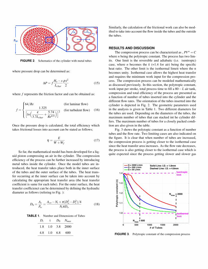
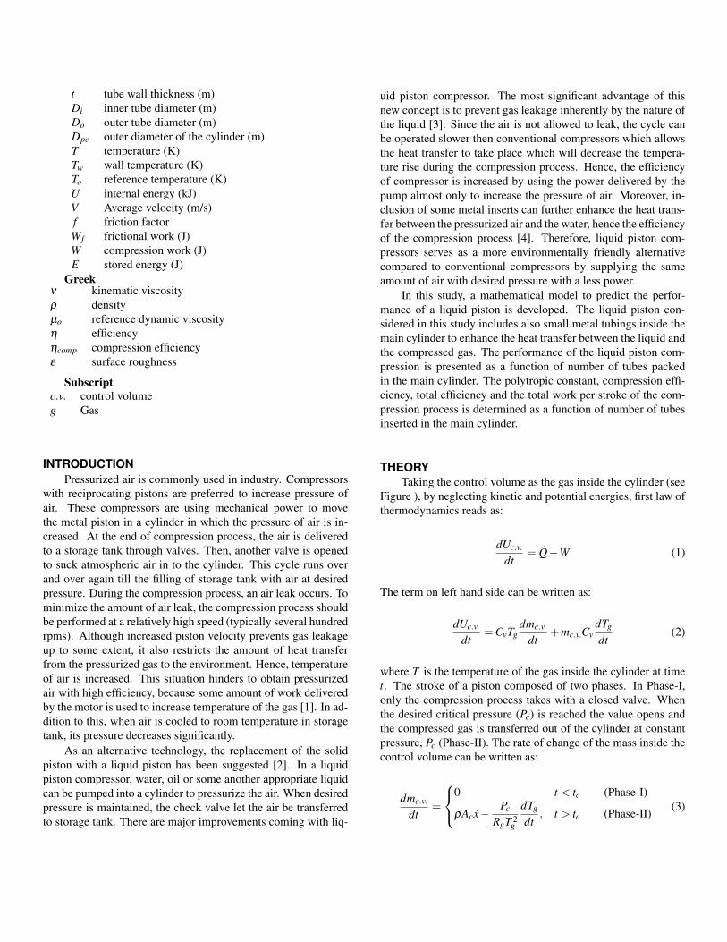
FIGURE 2. Schematics of the cylinder with metal tubes
where pressure drop can be determined as:
∆P = fHo− xLchar
ρ x2
2(15)
where f represents the friction factor and can be obtained as:
f =
64/Re (for laminar flow)
1.325[ln(
ε
3.7Lchar+
5.74Re0.9
)]2 (for turbulent flow) (16)
Once the pressure drop is calculated, the total efficiency whichtakes frictional losses into account can be stated as follows;
η =E
W +Wf(17)
So far, the mathematical model has been developed for a liq-uid piston compressing an air in the cylinder. The compressionefficiency of the process can be further increased by introducingmetal tubes inside the cylinder. Once the model tubes are in-troduced, the heat transfer takes place both in the inner surfaceof the tubes and the outer surface of the tubes. The heat trans-fer occurring at the inner surface can be taken into account bycalculating the appropriate heat transfer area (the heat transfercoefficient is same for each tube). For the outer surface, the heattransfer coefficienct can be determined by defining the hydraulicdiameter as follows (refering to Fig. ):
Dh =Ac
Pw=
Aco−Nt ×π(D2o−D2
i )/4NtπDo
(18)
TABLE 1. Number and Dimensions of Tubes
Di t D0 Nmax
1.8 1.0 3.8 2000
4.8 1.0 6.8 600
Similarly, the calculation of the frictional work can also be mod-ified to take into account the flow inside the tubes and the outsidethe tubes.
RESULTS AND DISCUSSIONThe compression process can be characterized as , PV n =C
where n being the polytropic constant. The process has two lim-its. One limit is the reversible and adiabatic (i.e. isentropic)case, where n becomes the k (=1.4 for air) being the specificheat ratio. The other limit is the isothermal limeit where the nbecomes unity. Isothermal case allows the highest heat transferand requires the minimum work input for the compression pro-cess. The compression process can be modeled mathematicallyas discussed previously. In this section, the polytropic constant,work input per stroke, total process time to fill a 80−L air tank,compression and total efficiency of the process are presented asa function of number of tubes inserted into the cylinder and thedifferent flow rates. The orientation of the tubes inserted into thecylinder is depicted in Fig. 2. The geometric parameters usedin the analysis is given in Table 1. Two different diameters forthe tubes are used. Depending on the diameters of the tubes, themaximum number of tubes that can stacked int he cylinder dif-fers. The maximum number of tubes for a closely packed condi-tion are also given in the table.
Fig. 3 shows the polytopic constant as a function of numbertubes and the flow rate. Two limiting cases are also indicated onthe figure. It is clear that when number of tubes are increased,the compression process is getting closer to the isothermal casesince the heat transfer area increases. As the flow rate decreases,the process is also getting closer to the isothermal case which isquite expected since the process getting slower and slower gas
0 500 1000 1500 2000# of Tubes
1.0
1.1
1.2
1.3
1.4
Poly
trop
ic c
onst
ant (
n)
Q = 3000 L/minQ = 300 L/minQ = 30 L/min
Isentropiclimit
Isothermallimit
Nmax = 600
Nmax = 2000
Solid Line: I.D. = 1.8mmDashed Line: I.D. = 4.8mm
FIGURE 3. Polytropic constant of the compression process
0 500 1000 1500 2000# of Tubes
0.1
1.0
10
100
Tota
l tim
e [s
]
Q = 30 L/minQ = 300 L/minQ = 3000 L/min
Solid Line: I.D. = 1.8mmDashed Line: I.D. = 4.8mm
Nmax = 600 Nmax = 2000
FIGURE 4. Total time to fill 80 L air tank
0 500 1000 1500 2000# of Tubes
500
750
1000
1250
1500
1750
2000
Tota
l Wor
k [J
/str
oke]
Q = 3000 L/minQ = 300 L/minQ = 30 L/min
Nmax = 2000Nmax = 600
Solid Line: I.D. = 1.8mmDashed Line: I.D. = 4.8mm
FIGURE 5. Total work per stroke of the compression process
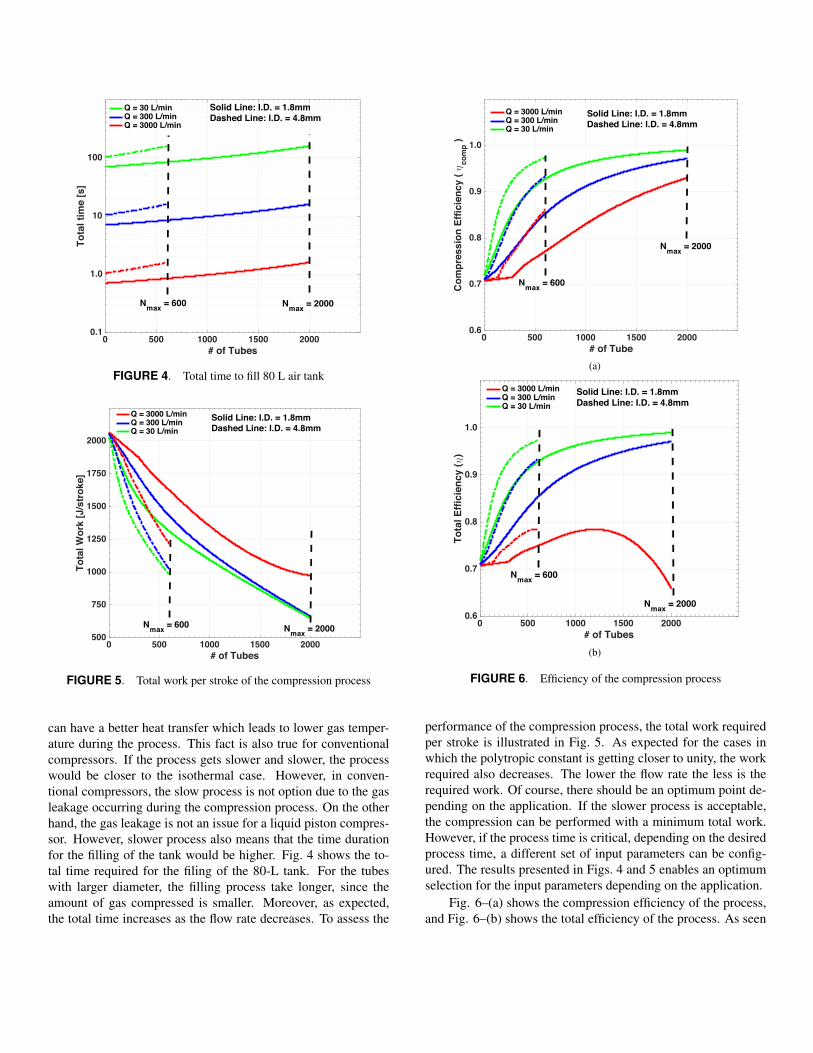
can have a better heat transfer which leads to lower gas temper-ature during the process. This fact is also true for conventionalcompressors. If the process gets slower and slower, the processwould be closer to the isothermal case. However, in conven-tional compressors, the slow process is not option due to the gasleakage occurring during the compression process. On the otherhand, the gas leakage is not an issue for a liquid piston compres-sor. However, slower process also means that the time durationfor the filling of the tank would be higher. Fig. 4 shows the to-tal time required for the filing of the 80-L tank. For the tubeswith larger diameter, the filling process take longer, since theamount of gas compressed is smaller. Moreover, as expected,the total time increases as the flow rate decreases. To assess the
0 500 1000 1500 2000# of Tube
0.6
0.7
0.8
0.9
1.0
Com
pres
sion
Effi
cien
cy ( η
com
p )
Q = 3000 L/minQ = 300 L/minQ = 30 L/min
Solid Line: I.D. = 1.8mmDashed Line: I.D. = 4.8mm
Nmax = 600
Nmax = 2000
(a)
0 500 1000 1500 2000# of Tubes
0.6
0.7
0.8
0.9
1.0
Tota
l Effi
cien
cy (η
)
Q = 3000 L/minQ = 300 L/minQ = 30 L/min
Nmax = 2000
Nmax = 600
Solid Line: I.D. = 1.8mmDashed Line: I.D. = 4.8mm
(b)
FIGURE 6. Efficiency of the compression process
performance of the compression process, the total work requiredper stroke is illustrated in Fig. 5. As expected for the cases inwhich the polytropic constant is getting closer to unity, the workrequired also decreases. The lower the flow rate the less is therequired work. Of course, there should be an optimum point de-pending on the application. If the slower process is acceptable,the compression can be performed with a minimum total work.However, if the process time is critical, depending on the desiredprocess time, a different set of input parameters can be config-ured. The results presented in Figs. 4 and 5 enables an optimumselection for the input parameters depending on the application.
Fig. 6–(a) shows the compression efficiency of the process,and Fig. 6–(b) shows the total efficiency of the process. As seen
previously, slower the compression process higher the compres-sion efficiency. Similar trend is also true for the total efficiencyexcept for the solid red curve in Fig. 6–(b). The trend is similarsince work accounted for the frictional losses is not the dominantone. However as the flow rate increases, and more and moretubes are presented, now the area of the gas decreases whichresults in higher velocities, and the frictional losses dominates.This is the reason for the solid red curve has a diminishing totalefficiency with increasing number of tubes.
CONCLUSIONLiquid piston compressor is an alternative technology which
aims to increase efficiency by preventing gas leakages and highheat transfer rates. Heat transfer is favorable since it allows tokeep temperature of air constant at a certain level, hence powerdelivered by the pump is consumed almost only to pressurizethe air. This is accomplished by decelerating the compression.Conventional compressor should operate at high frequencies inorder to minimize the gas leakage. Since leakage is not a con-cern in liquid piston compressor, the cycle may operate at lowfrequencies. This enables the system to work with increased heattransfer from air to the surroundings which leads to a process be-ing close to an isothermal one. A mathematical model has beendeveloped and presented in this paper which assess the effect ofdifferent design parameters on the process. It has been shownthat introducing metal tubing inserts into the cylinder, the pro-cess becomes more and more closer to being an isothermal one.One limiting case for the cylinder with the metal inserts is thetotal process time. Depending on the nature of the process, thedesign parameters can be optimized to obtain the desired perfor-mance within the certain limit of process time.
In this study, only the compression process and the dischargeof the compressed gas is modeled. The modeling of the expan-sion step and the inclusion of the heat transfer occurring at themetal tube walls will be our future research direction.
ACKNOWLEDGMENTFinancial support from the Turkish Scientific and Technical
Research Council (Project No: 1139B411501759) is greatly ap-preciated.
REFERENCES[1] de Ven, J. D. V., and Li, P. Y., 2009. “Liquid piston gas
compression”. Applied Energy, 86(10), pp. 2183 – 2191.[2] C. Qin, E. L., 2014. “Liquid piston compression efficiency
with droplet heat transfer”. Applied Energy, 114, pp. 539 –550.
[3] Shirazi, F. A., Saadat, M., Yan, B., Li, P. Y., and Simon,T. W., 2013. “Iterative optimal and adaptive control of a
near isothermal liquid piston air compressor in a compressedair energy storage system”. American Control Conference,pp. 2934–2939.
[4] Zhang, C., Simon, T. W., and Li, P. Y., 2013. “Optimiza-tion of the axial porosity distribution of porous inserts in aliquid-piston gas compressor using a one-dimensional for-mulation”. Heat Transfer and Thermal Engineering.