mathanakeerthi s assistant professor civil …
TRANSCRIPT

Clariflocculator in Waste Water Treatments
MATHANAKEERTHI S
ASSISTANT PROFESSOR CIVIL ENGINEERING
SNS COLLEGE OF ENGINEERING
• In large waste water treatment plants, the flocculator and the clarifier are combined together to achieve economy in construction. The combined unit of flocculator and clarifier is known as clariflocculator in waste water treatment process. Clariflocculator shall have two concentric tanks with inner tank serving as flocculation basin and outer tank serving as clarifier.
2 EN8491 - WATER SUPPLY ENGINEERING -SEM 5 - UNIT III - MATHANAKEERTHI S
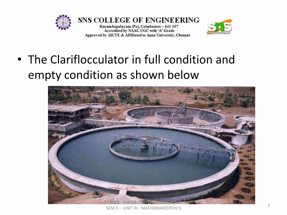
• The Clariflocculator in full condition and empty condition as shown below
3 EN8491 - WATER SUPPLY ENGINEERING -SEM 5 - UNIT III - MATHANAKEERTHI S

PLATE AND TUBE SETTLERS • Plate and Tube Settlers have been developed as an alternative to shallow basins
and are used in conjunction with both existing and specially designed sedimentation basins.
• Plate and Tube Settlers are shallow settling devices consisting of stacked offset trays or bundles of small plastic tubes of various geometries. They are used to enhance the settling characteristics of sedimentation basins.
• The shape, hydraulic radii, angle of inclination, and length of the plate and tube settlers will vary according to the particular installation.
• Normal practice is to insert the plate or tube settlers in sedimentation basins (either rectangular or circular) of sufficient depth. The flow within the basin passes upward through the plate or tube modules and exits from the basin above the modules. The solids that settle out within the plates or tubes move by means of gravity counter currently downward and out of the tube modules to the basin bottom.
4 EN8491 - WATER SUPPLY ENGINEERING -SEM 5 - UNIT III - MATHANAKEERTHI S
• To be self-cleaning, plate or tube settlers are usually set at an angle between 45° and 60° above the horizontal.
• When the angle of inclination of plate or tube is more than 60° the efficiency of the settling basin decreases. If the plates and tubes are inclined at angles less than 45°, settler will tend to accumulate solids, which must be flushed out periodically (usually with high pressure hose).
• The need for flushing poses a problem with the use of plate and tube settlers where the characteristics of the solids to be removed vary from day to day.
5 EN8491 - WATER SUPPLY ENGINEERING -SEM 5 - UNIT III - MATHANAKEERTHI S
• Tube settlers are a light weight structure composed of closely spaced tubes on an incline (usually between 45° and 60°). Clarifier up flow is passed through these tubes.
• Settling within these tubes and contact clarification of fine floc results in a build-up of particles on the tube surfaces.
• Particles combine to form agglomerates which become heavy enough to slough against the upward flow and slide down the tube slope to join the sludge blanket below.
6 EN8491 - WATER SUPPLY ENGINEERING -SEM 5 - UNIT III - MATHANAKEERTHI S
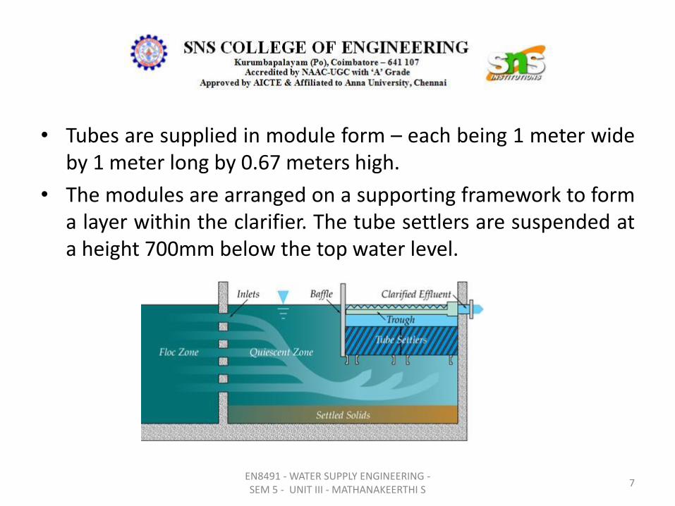
• Tubes are supplied in module form – each being 1 meter wide by 1 meter long by 0.67 meters high.
• The modules are arranged on a supporting framework to form a layer within the clarifier. The tube settlers are suspended at a height 700mm below the top water level.
7 EN8491 - WATER SUPPLY ENGINEERING -SEM 5 - UNIT III - MATHANAKEERTHI S

Clarifier with Plate Settler
8 EN8491 - WATER SUPPLY ENGINEERING -SEM 5 - UNIT III - MATHANAKEERTHI S
High Rate Settlers • High rate tube settlers are designed to improve the
characteristics of the rectangular basin and to increase flow through the tank.
• The tube settlers consist of a series of tubes that are installed at a 600 angle to the surface of the tank. The flow is directed up through the settlers.
• Particles have a tendency to flow at an angle different than the water and to contact the tube at some point before reaching the top of the tube.
• After particles have been removed from the flow and collected on the tubes, they tend to slide down the tube and back into the sludge zone.
9 EN8491 - WATER SUPPLY ENGINEERING -SEM 5 - UNIT III - MATHANAKEERTHI S

Arrangements of Tube Settlers in Rectangular Tank
10 EN8491 - WATER SUPPLY ENGINEERING -SEM 5 - UNIT III - MATHANAKEERTHI S

Advantages of tube settlers
• Solids removal efficiency will be higher leading to clarified water turbidity as less than 10 NTU
• Hence the load on the filter will be less.
• Treatment plant capacity of the existing Water treatment Plant could be increased by 50 to 60%
11 EN8491 - WATER SUPPLY ENGINEERING -SEM 5 - UNIT III - MATHANAKEERTHI S
Advantages of Plate settlers
• Compact design: Space saving; Cost saving
• No moving parts: Low maintenance; No spare parts
• Simple installation: Saves money; Immediate start-up at full capacity
• Ease of access: Individual removal of each lamella plate; Easily available for inspection
• Sludge handling benefits: High underflow sludge concentration; Low cost for sludge withdrawal
• Flexible system : Retrofitting of existing tank; Custom design;
12 EN8491 - WATER SUPPLY ENGINEERING -SEM 5 - UNIT III - MATHANAKEERTHI S
Disadvantages of Tube settlers / plate settlers
• Algae growth in tubes and plates may cause maintenance and odor problems.
• Easy to clean in Lamella but not in Tubular Module.
• Careful attention is necessary for ,the design of inlet and outlet structures to avoid turbulence and uneven flow.
• Sometimes high pressure hose water is injected to flush out the solids.
13 EN8491 - WATER SUPPLY ENGINEERING -SEM 5 - UNIT III - MATHANAKEERTHI S
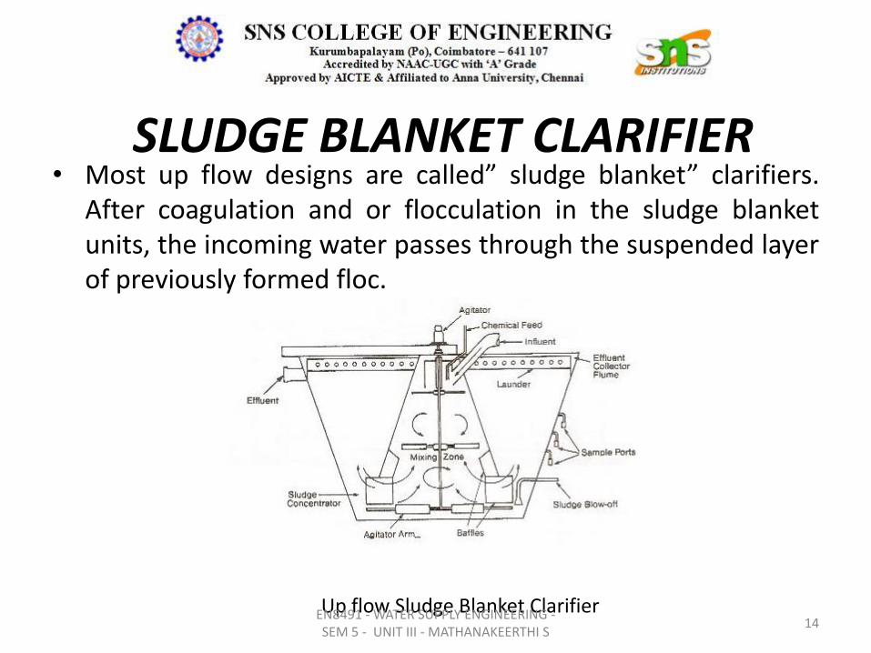
SLUDGE BLANKET CLARIFIER • Most up flow designs are called” sludge blanket” clarifiers.
After coagulation and or flocculation in the sludge blanket units, the incoming water passes through the suspended layer of previously formed floc.
Up flow Sludge Blanket Clarifier 14
EN8491 - WATER SUPPLY ENGINEERING -SEM 5 - UNIT III - MATHANAKEERTHI S
• Because the center-well in these units is often shaped like an inverted cone, the rise rate of the water decreases as it rises through the steadily enlarging cross section.
• When the rise rate, decreases enough to equal the settling rate of the suspended floc exactly, a distinct sludge/ liquid interface forms.
• Sludge blanket efficiency depends on the filtering action as the freshly coagulated or flocculated water passes through the suspended floc.
15 EN8491 - WATER SUPPLY ENGINEERING -SEM 5 - UNIT III - MATHANAKEERTHI S
• Higher sludge levels increase the filtration efficiency.
• In practice, the top sludge interface is carried at the highest safe level to prevent upsets that might result in large amounts of floc carryover into the overflow.
• Excessive sludge withdrawal or blow down should also be avoided.
• The sludge blanket level is often highly sensitive to changes in throughput, coagulant addition, and changes in raw water chemistry and temperature.
16 EN8491 - WATER SUPPLY ENGINEERING -SEM 5 - UNIT III - MATHANAKEERTHI S
PULSATOR CLARIFIER • The original Pulsator Clarifier was developed in the early
1950′ s.
• Now it is a properitory item designed and installed by M/ s Degremont private Ltd.
Components of Pulsator clarifier are:
– Vacuum chamber, vacuum pump and vent valve
– Raw water distribution channel and perforated distribution pipes.
– Lamellar Plates and/ or Tubes for clarification.
– Clarified water collection laterals and channel.
17
EN8491 - WATER SUPPLY ENGINEERING -SEM 5 - UNIT III - MATHANAKEERTHI S
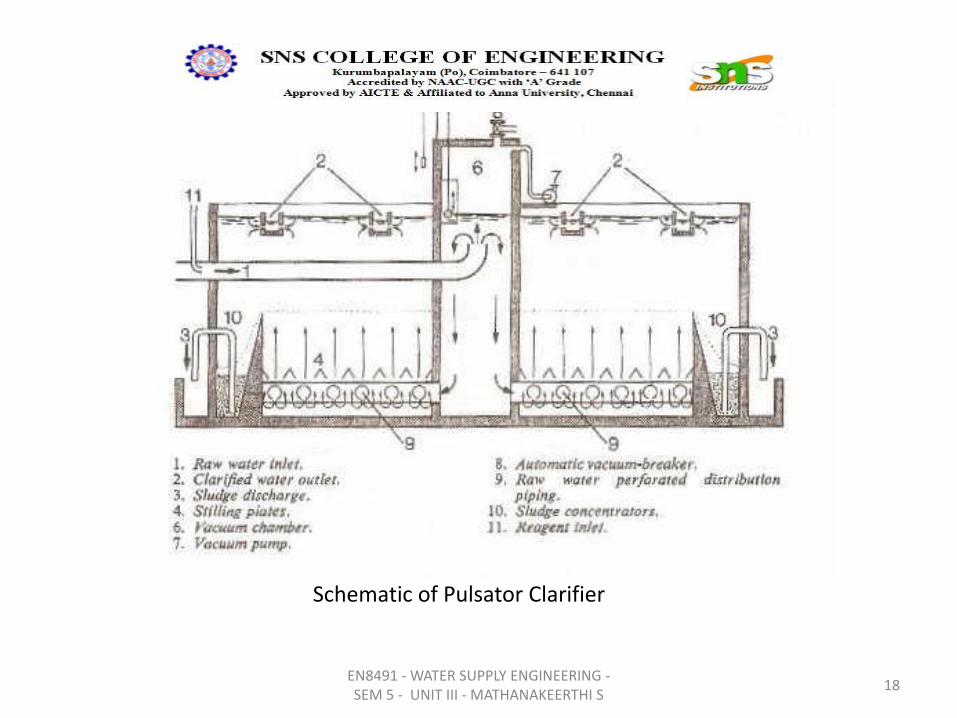
Schematic of Pulsator Clarifier
18 EN8491 - WATER SUPPLY ENGINEERING -SEM 5 - UNIT III - MATHANAKEERTHI S
Working Principles of Pulsator Clarifier
• It consists of a flat-bottom tank with a series of perforated pipes at its base to distribute the raw water
uniformly over the entire bottom
• Coagulated water to pulsator flow intermittently through perforated pipes
• Coagulant water is stored in the upper part of the vacuum chamber for a given period by creating vacuum.
• The hydraulic force is then released, and the coagulated water is pulsed at a high velocity through
distribution pipes into the Pulsator.
• Sludge blanket in the pulsator flocculates and remove the particles.
• A set of channels (launders) is provided at the top of the Pulsator to collect the clarified water evenly.
• By removing the air by suction from the vacuum chamber vacuum is created. As a result, the water level
rises gradually inside the vacuum chamber. When it reaches a set level between 0.35 m and 0.45 m above
the Pulsator water level, a contact suddenly opens an air inlet valve.
19 EN8491 - WATER SUPPLY ENGINEERING -SEM 5 - UNIT III - MATHANAKEERTHI S

• The sludge blanket in the bottom part of the Pulsator is subjected to alternating vertical motions. It expands when the water rushes from vacuum chamber during drop, for a short time (5 -20 sec.) and then shrinks (packs) during vacuum creation which lasts 25 – 50 seconds.
• Thus once in about 60 sec the water is pushed into pulsator through sludge blanket and the sludge blanket expands and shrinks once during that time.
• Frequency of pulsing is adjusted according to turbidity in raw water; For high turbidity shorter pulse interval (30 to 40 sec) and for low turbidity longer pulse interval 45 to 60 sec) is provided.
• The sludge blanket gradually increases in volume due to entrapping the impurities contained in the feed water. When the level of the sludge blanket rises above a specified level (weir level), and sludge spills into the concentrators.
• Sludge concentrator contains number of hopper bottomed tanks; The sludge is extracted from the concentrators at regular intervals.
20
EN8491 - WATER SUPPLY ENGINEERING -SEM 5 - UNIT III - MATHANAKEERTHI S