materials, structures and manufacturing: an integrated ... · pdf fileamerican institute of...
TRANSCRIPT
American Institute of Aeronautics and Astronautics
1
Materials, Structures and Manufacturing: An Integrated Approach to Develop Expandable Structures
W. Keith Belvin1
NASA Langley Research Center, Hampton VA 23681
Martin E. Zander2 TU Braunschweig / DLR German Aerospace Center, 38108 Braunschweig Germany
David W. Sleight3, John Connell4, Nancy Holloway5 NASA Langley Research Center, Hampton VA 23681
and
Frank Palmieri6 National Institute of Aerospace, Hampton VA 23666
Membrane dominated space structures are lightweight and package efficiently for launch; however, they must be expanded (deployed) in-orbit to achieve the desired geometry. These expandable structural systems include solar sails, solar power arrays, antennas, and numerous other large aperture devices that are used to collect, reflect and/or transmit electromagnetic radiation. In this work, an integrated approach to development of thin-film damage tolerant membranes is explored using advanced manufacturing. Bio-inspired hierarchical structures were printed on films using additive manufacturing to achieve improved tear resistance and to facilitate membrane deployment. High precision, robust expandable structures can be realized using materials that are both space durable and processable using additive manufacturing. Test results show this initial work produced higher tear resistance than neat film of equivalent mass. Future research and development opportunities for expandable structural systems designed using an integrated approach to structural design, manufacturing, and materials selection are discussed.
I. Introduction xpandable structural systems can revolutionize the application of large apertures in space missions, enable many new missions (e.g. power systems, solar sails, aerodynamic decelerators), and permit shape changing features
for aerospace vehicles to achieve mission adaptability. Figure 1 shows four classes of expandable structures applications: large in-space systems; pressurized systems including habitats; entry, descent and landing systems; and morphing systems. These predominantly membrane structures provide mission enabling geometric dimensions with very low mass/area (areal density) and they can be packaged in small volumes for launch and transit (Ref. 1). The cost savings of expandable structures have the potential to change the economics of space exploration and enable human exploration of asteroids and the inner solar system. However, this class of structural system must earn its way into aerospace applications by developing a rigorous knowledge base for design (materials and structures), analysis, testing, fabrication, deployment, and shape control. 1 Principal Investigator, NASA Office of Chief Technologist, Mail Stop 250, AIAA Associate Fellow. 2 Aerospace Engineer, Technische Universität Braunschweig & DLR German Aerospace Center, Institute of
Composite Structures, Lilienthalplatz 7. 3 Aerospace Engineer, Research Directorate, Mail Stop 188E, AIAA Senior Member. 4 Aerospace Engineer, Research Directorate, Mail Stop 226. 5 Aerospace Technologist, Engineering Directorate, Mail Stop 390. 6 Research Engineer, 100 Exploration Way.
E
https://ntrs.nasa.gov/search.jsp?R=20120008170 2018-05-25T21:49:10+00:00Z

American Institute of Aeronautics and Astronautics
2
As previously stated, the high pay-off of expandables is accompanied by high risk. Technology advances are needed to reduce or eliminate the largest known risks, specifically:
Long life durability and damage tolerance – Mission Environment Compatibility Achieving precision requirements – Deployment and Dimensional Control Deployment/Expansion Reliability – Reduced Complexity and Mass Operational Safety – Design/Diagnostics/Certification
In many applications, such as inflated habitats and aeroshells, expandable structures are fiber reinforced or built from fabrics that exhibit a high degree of in plane strength and the fibers provide inherent rip stop. Conversely, large in-space systems are typically designed for stiffness not strength, and the need for low areal mass density result in the use of thin films instead of fabric membranes. These systems are highly susceptible to tearing (Ref. 2-3). In this work, a novel combination of materials, structures and manufacturing technology is explored for development of thin-film damage tolerant membranes. Bio-inspired hierarchical structure was “printed” on films using additive manufacturing to achieve improved tear resistance and to facilitate membrane deployment. Test results show this initial work produced higher tear resistance than neat film of equivalent mass. In the following sections, biologic inspiration for design of thin hierarchical structures is discussed. Subsequently a new application of additive manufacturing is shown to create large scale, fine feature thin film structures at very low cost. Experimental data for various levels of hierarchy are presented to show the efficacy of the proposed approach. Finally, future directions for maturation of the proposed technology are summarized.
Figure 1. Expandable Structures Applications
II. Durability, Damage Tolerance, and Self-Deployment – Biologic Inspiration
The reliability of structural systems can be enhanced by taking a hierarchical approach to design that prevents progressive failure by redistributing loads around a damaged area. For example, space debris impact damage can be localized if proper damage tolerant design approaches are used. Ultra-light weight structures originate in nature as one can see for example on insect wings, feathers, spider webs, leaves and airfoils like bat wings. Therefore, several interesting and applicable principles were evaluated during the conceptual phase of this work. Some remarkable principles are briefly described in this section. Principles of ultra-light membrane structures from nature, especially from leaves and insect wings, can be applied to the proposed hierarchical design. While leaves are, in most cases, built up symmetrically from central primary veins to secondary and tertiary veins, the structure of an insect wing is often not symmetrical. Insect wings consist of two types of structure, veins and the membrane, constituting generally only 0.5–5% of the body mass. Both consist of cuticle which is composed of the material chitin. The veins provide the primary structural support for the wings,

American Institute of Aeronautics and Astronautics
3
Figure 2. Wing structure of a dragonfly.
(Jim Johnson, Identification: Dragonflies versus Damselflies, May 9, 2011, http://nwdragonflier.blogspot.com/2011/05/identification-dragonflies-versus.html )
thicker surrounding structures provide stiffness (leading and trailing edge), and thinner intermediate structures provide less stiffness and provide some damage tolerance (Ref. 4-5). On dragonflies, for example, the membrane is very thin, with a thickness of only 2 to 3 µm as shown in Fig. 2. A. Damage tolerance Damage tolerance can be found in insect wings which accumulate damage but remain functional. Wing damage can be seen on dragonflies ranging from minor tattering to the loss of large wing sections, especially towards the trailing edge and wing tips. It was also found that a loss of up to 30% total wing area influenced flight behavior but still enabled the insects to fly. This indicates a membrane rip-stop quality as the damage must not have propagated since only a few cases resulting in the inability to fly were reported (Ref. 4). One interesting characteristic to note about a dragonfly wing is that there are several different kinds of patterns present in the wing vein framework. The leading edge consists primarily of rectangular frames whereas the trailing surface is largely formed of hexagons and some other polygons with more than 4 sides as depicted in Fig. 2. The principle appears to be that the chitin material acts to limit damage in one part of the wing from propagating by localizing the damage. The cuticle (veins) redistribute load around damaged areas. B. Self-deployment Self-Deployment and self-folding is also found in insect wings. Any winged insect, when it transforms into the adult stage has to expand the wings from short stubby highly folded bags into long thin stiff membranes, which is done by pressurizing (inflation). Unfolding of wings in adult insects is basically achieved and controlled from the wing base, whereas folding in most cases is possible only by using additional structures, like forewings and abdomen. An unfolding supporting intrinsic elastic mechanism within the wing membrane was found and demonstrated self-deployment in several beetle species (Coleoptera, Ref. 6). In earwig bugs, the wing venation and folding pattern, shown in Fig. 3, is unique among insects especially in two aspects: the veins radiate from the center of the hind wing, rather than from its base, and the large fan is folded four times, once radially and twice transversely and fourthly the whole wing folds longitudinally. This four-fold folding is actually done in one combined movement after the wing stiffening mechanisms are released. The area of the unfolded wing is ten times greater than the area of the stowed wing. Mechanical experiments have shown that the earwig (dermapteran) hind wing is actually folded by intrinsic elasticity, stored by resilin in well-defined patches in the wing veins. The resilin is a rubber-like protein also found in the vein joints of wings of dragonflies (Odonata) to enable controlled torsion, essential to flapping flight. The vein structure, the membrane, the material elasticity (resilin distribution) and the folding pattern play an important role for self-deployment and packaging in insect wings and are also inspiring for deployment concepts for large in-space membrane systems.

American Institute of Aeronautics and Astronautics
4
Figure 3. a) Schematic view of the earwig hind wing with resilin concentrations (blue) in joints and fold lines;
b) Earwig deploys its wings with the cerci . (Ref. 6)
III. Additive Manufacturing Incorporating small-feature hierarchical structures as occur in nature on large scale thin film space structures would be prohibitive without advances in manufacturing. Typically, rip-stop or other features are added to membrane structures either manually by bonding some form of reinforcement to the film or by robotic assisted thermal bonding of simple geometry seams (Ref. 7). Manual bonding often leads to excess adhesive, wrinkling and unwanted thermal deformation due to the use of dissimilar materials. To enable large scale and complex geometry reinforcements, a new process is proposed based on direct build on the film using robotic assisted additive manufacturing. This process, invented by the authors, is patent pending (Ref. 8). The successful integration of small feature substructure on a film is strongly dependent on compatible manufacturing processes and materials (Ref. 9). For large space systems, a process that can achieve fine detail in the hierarchical structure but that can also be scaled up for roll-to-roll processing of large area films was needed. The proper choice of materials and manufacturing process is necessary to provide compatibility between the reinforcement and the film materials and to ensure sufficient bonding between the added build structure and the film. Several different manufacturing techniques, processes and build materials were tested with several relevant film materials. This integrated approach to selection of the materials, structure and manufacturing led to successful demonstration of the method in Ref. 8 and is described in the following sections. A. Building Structures on Films with Fused Deposition Modeling Technology Manufacturing with fused deposition modeling (FDM) technology using a STRATASYS® FDM 400 mc 3D production system was performed on various film thicknesses and film materials (polycarbonate, Kapton®, and CP1) . Fused deposition modeling is a manufacturing technology commonly used for modeling, prototyping, and production applications, where thermoplastic build and support material is precisely deposited layer-by-layer, to form the part. The thermoplastic material is heated up to about 350 °C, melting in an extrusion nozzle and then deposited on the film, which is held down on a vertically movable table with vacuum suction. The material hardens immediately after extrusion from the nozzle due to cooling. The nozzle is moved in horizontal directions by a numerically controlled mechanism, following a prescribed tool path. For the proof of concept rip-stop structures printed with FDM technology in this study, an example shown in Fig. 4, the maximum build envelope (XYZ) was 406 x 356 x 406 mm (16 x 14 x 16 in) due to use of an existing system. The build chamber is air circulation heated and kept at a constant temperature of approximately 145 °C during the build process. To print a prototype, the rip-stop structure geometry was generated in a computer aided design (CAD) program and exported to the STRATASYS® FDM 400 controller. Extension of the proposed additive manufacturing technology to large scale membrane structures using a roll-to-roll process is described in section V. ® STRATASYS is a Registered Trademark of STRATASYS Inc. ® Kapton is a Registered Trademark of Dupont Corporation
b a
American Institute of Aeronautics and Astronautics
5
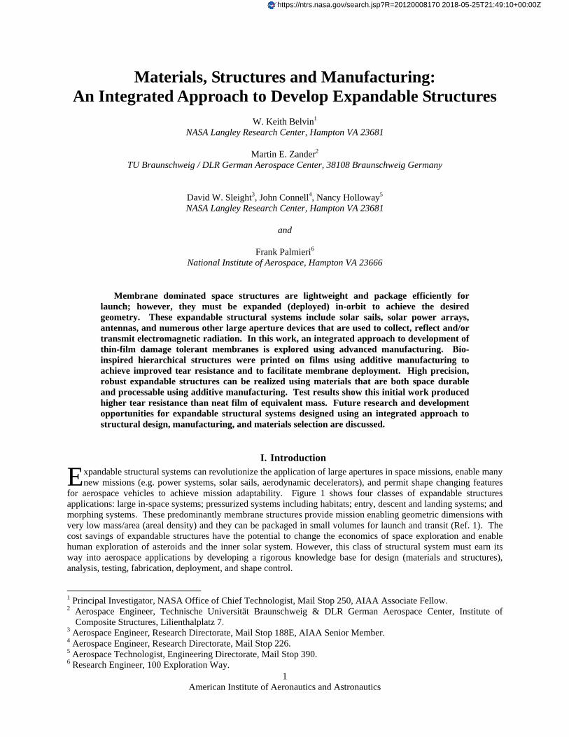
Figure 4. Typical specimen mounted in test frame with elliptical FDM reinforcements B. Experimental Specimens Six series of specimens were designed and built. All specimens were made of isotropic cast polycarbonate film, Makrofol N® grade (Bayer®), with a thickness of 0.02 mm (0.8 mil), purchased at the Goodfellow Corporation, USA. All applied structures were made of polycarbonate as it is the build material of the FDM manufacturing process available for this study. Each of the specimens was designed for tensile testing described in the following section to study tear propagation. Reference 10 is a notable contribution on membrane tearing and also provides an excellent review of prior work. The specimens were designed to assess tearing of the films also referred to as crack growth in Ref. 11 (the terms crack growth and tearing are used interchangeably herein). For this study, the specimens can be categorized by their main dimensions in two specific types, the so called Small Specimen Type, consisting of two specimen series and the Large Specimen Type, consisting of four specimen series. 1. Small Specimen Type Two series can be classified in the Small Specimen Type. One series of plain film called Plain Film Specimen, serves as a reference (or control specimen) without any rip-stop structure featuring just the main dimensions of the Small Specimen Type. Figure 5 depicts this specimen series with the main dimensions L1, h1 and a1 and also shows the clamping edges as hatched clamping zones. The Small Specimen Type main dimensions were length L1= 254 mm (10 in), the height h1= 63.5 mm (2.5 in) and with an applied initial center slit length (or crack), oriented parallel to the longest side of the specimen, with the initial crack length of a1= 76.2 mm (3 in). A clamping edge (also referred to as the clamping zone) along their longest side of the specimen had a width of 6.35 mm (0.25 in). The second specimen, shown in Fig. 6, features 6 polycarbonate rip-stop line structures, oriented perpendicular to the initial crack. The rip-stop lines were symmetrically arranged to the specimen and have different widths. The rip-stop line closest to the tip of the initial crack has a line-width of 0.254 mm (0.01 in), increasing to 0.508 mm (0.02 in) in width for the next line, to 0.762 mm (0.03 in) in width for the lines furthest from the crack tip and closest to the edge of the specimen. All of the rip-stop lines have a thickness of 0.1778 mm (0.007 in) and a length of 38.1 mm (1.5 in). The lines on each side of the initial crack reinforcements are spaced 25.4mm (1 in) from another, while the inner lines are 12.7 mm (0.5 in) distanced from the corresponding crack tip, thus assuring sufficient ligament length for the tear to develop a stable propagation speed before hitting the first rip-stop line when tested.

American Institute of Aeronautics and Astronautics
6
Figure 5. Plain film specimen Figure 6. Film specimen with six rip-stop lines
2. Large Specimen Type The first Large Specimen Type, the Elliptical rip-stop specimen series, features a rip-stop structure consisting of 3 cascaded ellipses, centered and rotated relative to the main dimensions of the specimen as depicted in Fig. 7. In this series, the specimens had a film thickness of 0.02 mm (0.8 mil). Four series of specimens with the main dimensions: length L2= 254 mm (10 in) and height h2= 139.7 mm (5.5 in), made up the Large Specimen Type. All specimen series within this specimen type exhibit different initial crack lengths and crack orientations according to the specific specimen series design. The large radii of the ellipses, starting with the inner ellipse and moving outward to the specimen edge, are 15.24 mm (0.6 in), 40.64 mm (1.6 in) and 66.4 mm (2.6 in), while the corresponding small radii are 10.46 mm (0.412 in), 27.89 mm (1.098 in) and 45.34 mm (1.785 in). The relation of large radius to the corresponding small radius of one ellipse was inspired by the elliptical shaped wings of the earwig bug. The different widths of the rip-stop lines are, starting with the inner ellipse and moving outward to the specimen edge, 0.254 mm (0.01 in), 0.508 mm (0.02 in) and 0.762 mm (0.03 in). The measured thickness of all rip-stop ellipses is 0.1778 mm (0.007 in) and the initial crack length aE is 12.7 mm (0.5 in).
Figure 7. Film specimen with elliptical rip-stop structure (rotated 45°)
Another form of large specimen types featured hexagonal rip-stop structures. As shown in Fig. 8, two test specimens were fabricated with the same main dimensions as the Large Specimen Type. The regular hexagon shaped rip-stop structure was 96.52 mm (3.8 in) in diameter of the circumscribed circle. The hexagonal rip-stop cell is oriented with two opposite sides parallel to the longer edges of the specimens. The structural line itself has a width of 0.254 mm (0.01 in), a thickness of 0.02 mm (0.8 mil) and the corners of the hexagonal shape are rounded off to a radius of 2.54 mm (0.1 in). The differences between the two similar specimens are the arrangement of the hexagonal rip-stop structure on the specimens and the dimension and orientation of the initial cracks. The Hexagonal rip-stop specimen series has a horizontal initial center crack with a length of aH= 50.8 mm (2 in) and a 26.9 mm (1.06 in) vertical off-center shift in the hexagonal rip-stop cell. In Fig. 8a the arrangement of the shifted hexagonal structure relative to the main dimensions of the specimen, L2 and h2, as well as the horizontal center crack with its length aH are shown. The 45°-initial crack with a length of aH45= 45.72mm (1.8 in), the main dimensions L2 and h2, the centered hexagonal rip-stop cell and the clamping zone are depicted schematically in Fig. 8b.

American Institute of Aeronautics and Astronautics
7
Figure 8. a) Hexagonal Film specimen with crack vertically off-center
b) Hexagonal Film specimen with 45° tilted initial crack
The last specimen series, shown in Fig. 9, is the Soccer ball specimen which features a hierarchical structure, comprised of hexagon-cell structures within a circular boundary. The cell structure is based on regular hexagons with a diameter of 34.54 mm (1.36 in) for the circumscribed circle for each hexagonal cell. A large circular structure line encloses the hierarchical cell structure with a diameter of 114.55 mm (4.51 in). In the specimen´s center the by 45° counter-clockwise tilted initial crack (relative to the horizontal) can be found with the initial crack length aS= 20.32 mm (0.8 in).
Figure 9. Film specimen with a hierarchical soccer ball structure and a 45° tilted initial crack
IV. Test Method and Results A tensile test was performed to measure the load and displacement and to show visually the tear propagation behavior for the earlier specified rip-stop concepts. The measured load-displacement curves are used to show the effectiveness of the hierarchical structure concept as a rip-stop feature. The procedure uses video imaging to detect tear growth, to monitor the overall behavior of the specimens under load, and to record the load (independent variable) as a constant displacement rate of the boundary was introduced (displacement control). The fracture behavior of thin films is quite different from that of bulk materials. The reason for this is that the state of stress at the crack tip is affected by the thickness. When a tensile load is applied to a plate with an initial crack, there is large stress intensity near the crack tip. This results in the creation of a “plastic zone,” a region of material that is at its yield stress, along the crack tip. This yielded region experiences a lateral Poisson contraction. In a thick plate, the large bulk of the material along the width of the crack tip largely prevents this contraction, or compressive strain, from taking place. Therefore, this condition is called plane strain. In a thin film, however, the size of the plastic zone is often the same size as, or larger than, the film thickness. The material in the plastic zone can contract in the thickness direction. Because of this free contraction, the stress in the thickness direction stays approximately the same as that at the free surface. This condition results in a biaxial stress in the plane of the film.
a b
American Institute of Aeronautics and Astronautics
8
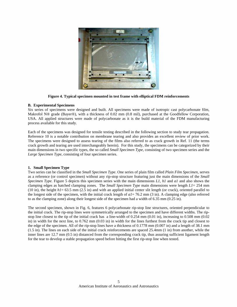
A constant force F was applied to the film perpendicular to the tear direction so that a mode 1 crack opening type occurs. The test setup is shown in Fig. 10, where L and h are the initial dimensions of the sheet and a is the length of the initial central crack cut in the film prior to testing. Note that h is the height of the specimen in theory. For practical reasons such as clamping, the specimen needs to have additional area and therefore a larger height to do so.
Figure 10. Film tension test
The apparatus used to perform the tension test was the material testing system INSTRON® 5848 Micro Tester made by the U.S. Company INSTRON®. The arrangement of the test setup with camcorder, specimen, the contrast screen and the digital display are shown in Fig. 11.
Figure 11. Arrangement of a) camcorder, b) mounted specimen, c) contrast screen and d) digital display A. Experimental Results Two hypotheses were evaluated in the experimental effort. The first was to evaluate the principle of stopping and/or pausing the tear propagation for a certain range of loading and displacement. This would prove the hypothesis that adding the hierarchical structure would improve the damage tolerance as compared to the control specimen. It was anticipated that the augmented films would show an increase in the maximum load (and extension) that the film could withstand before the tear would propagate through the whole specimen (specimen breakage). For the film specimens with the rip-stop lines perpendicular to the preexisting tear, the steady tear growth was expected to stop when the tear tip encounters the first rip-stop line, and then either propagates around the rip-stop, tears through the rip-stop, or propagates underneath (overcoming the bonding between rip-stop lines and film). This mechanism was expected for all three lines on each side of the specimen. As a result, several steps, ideally three if the tear propagation is symmetrical, were expected in the recorded load-displacement curve. The second aim of the tests was to prove the hypothesis of leading/guiding a tear to a different direction by turning the propagation path with a rip-stop line at an angle to the propagating tear. Turning the tear direction repeatedly in an area surrounded by a closed rip-stop cell would effectively localize the damage. The results were expected to be seen as steps in the load-displacement curves and in tear orientation changes in the video images.
b
d
c
a
American Institute of Aeronautics and Astronautics
9
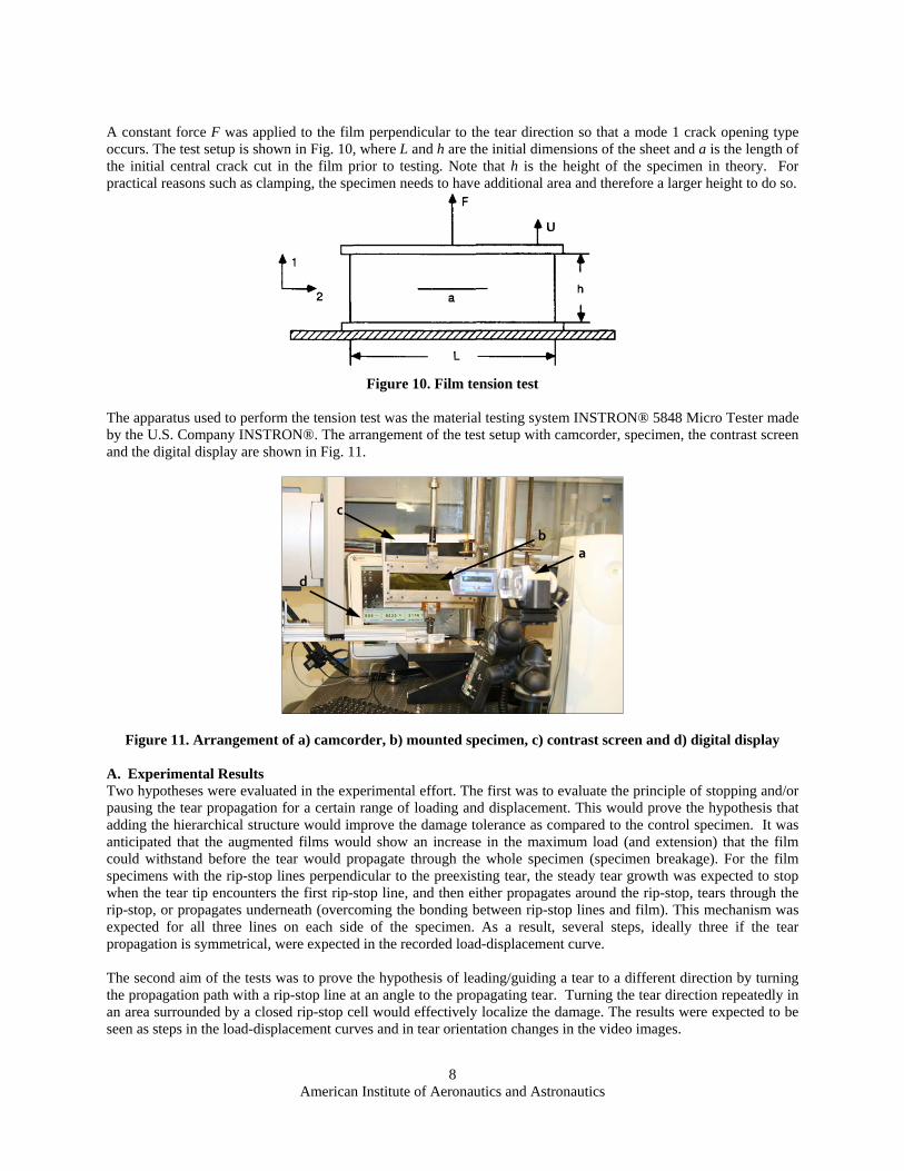
1. Small Specimen Type The load-displacement curve shown in Fig. 12 for plain film without any rip-stop feature (control specimen), shows an almost linear slope until the load maximum is reached and a sudden drop of load as tearing of the film occurs. Wrinkles in the film caused non-linearity in the response at the onset of specimen loading, which was corrected by extrapolating the linear portion of the curve to zero load in subsequent data analysis. This is true for all specimens (with and without rip-stop features) tested within this work. For the plain film specimen, the tear propagation dynamics involved a steady pace of tear propagation after the tear opened, followed by sudden rupture.
Figure 12. Load-displacement (extension) curve of a Plain film specimen
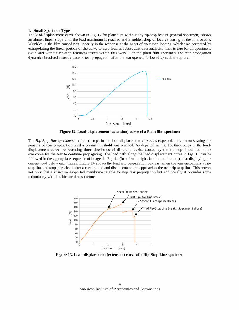
The Rip-Stop line specimens exhibited steps in the load-displacement curves as expected, thus demonstrating the pausing of tear propagation until a certain threshold was reached. As depicted in Fig. 13, three steps in the load-displacement curve, representing three thresholds of different levels, caused by the rip-stop lines, had to be overcome for the tear to continue propagating. The load path along the load-displacement curve in Fig. 13 can be followed in the appropriate sequence of images in Fig. 14 (from left to right, from top to bottom), also displaying the current load below each image. Figure 14 shows the load and propagation process, when the tear encounters a rip-stop line and stops, breaks it after a certain load and displacement and approaches the next rip-stop line. This proves not only that a structure supported membrane is able to stop tear propagation but additionally it provides some redundancy with this hierarchical structure.
Figure 13. Load-displacement (extension) curve of a Rip-Stop Line specimen
Neat Film Begins Tearing
First Rip‐Stop Line Breaks
Second Rip‐Stop Line Breaks
Third Rip‐Stop Line Breaks (Specimen Failure)

American Institute of Aeronautics and Astronautics
10
Figure 14. Sequence of a Rip-Stop Line specimen images and under displacement control
2. Large Specimen Type The path of the load-displacement curve of the Elliptical rip-stop specimens exhibited fewer steps than the straight rip-stop lines. In most cases a second load step drop did not occur after the peak load occurred. However, the load-displacement curve, shown in Fig. 15, does show a second load step jump after the maximum peak load occurred. The loading in the corresponding image sequence is shown in Fig. 16 (from upper left to lower right). The peak load can be identified when the tear propagation is stopped within the inner ellipse. The second load step jump in the curve occurred while the tear was kept between the second elliptical rip-stop on the left and the outer elliptical rip-stop on the right at 191.4 N. After this, the specimen suddenly ruptured, as seen as a steep load drop in the load-displacement curve. The tear propagated in all specimens of this series horizontally; turning of the tear in a different direction was not observed.
Figure 15. Typical load-displacement curve of an Elliptical rip-stop specimen

American Institute of Aeronautics and Astronautics
11
Figure 16. Tear propagation through an Elliptical rip-stop specimen during test
B. Experimental Results Summary Essential values of the tested specimens, averaged over multiple tests, are presented with an uncertainty of one standard deviation (+/- ) in Table 1. The values for the specimens of the Large Specimen Type (Elliptical rip-stop specimen, Hexagonal rip-stop specimen, Hexagonal 45 rip-stop specimen and Soccer ball specimen) seem to show that the additive film structure (indicated by mass of the specimens) increased both the maximum load and extension that the film can carry before failure. From the initial results of this study, we conclude:
1. Rip-stop lines impeded tear propagation resulting in load-displacement curves with steps as anticipated. A 14.3 % (164.4 N/143.8 N) weight normalized improvement in load capacity over plain films was observed.
2. A tear was kept in a closed rip-stop cell for a certain load span; until the displacement control produced a high enough load to fail the rip-stop line. This was observed in all specimens of the Large Specimen Type.
3. The idea that tear direction can be turned for localization was not proven. Constant rate displacement control may have contributed to an artificial loading condition that prevents turning of the crack direction.
Table 1. Essential values of tested specimens
Specimen series Film Thickness
[µm] +/-
Weight [g]
+/-
Number of tests
Average maximum load Fmax
[N] +/-
Average maximum
extension Umax [mm] +/-
Plain film specimen 21.0
+/- 1.0 0.3789
+/- 0.0038 6
143.8 +/- 3.9
2.47 +/- 0.17
Rip-Stop lines specimen (weight-normalized)
21.0 +/- 1.0
0.4013 +/- 0.0027
6 174.1
(164.4) +/- 3.9
3.64 +/- 0.23
Elliptical rip-stop specimen
21.0 +/- 1.0
0.9084 +/- 0.0040
4 264.8
+/- 2.1 6.18
+/- 0.15
Hexagonal rip-stop specimen
21.0 +/- 1.0
0.8097 +/- 0.0181
5 157.1
+/- 2.8 4.27
+/- 0.23
Hexagonal 45 rip-stop specimen
21.0 +/- 1.0
0.8369 +/- 0.0047
5 170.5
+/- 7.0 4.83
+/- 0.62
Soccer ball specimen 21.0
+/- 1.0 0.8739
+/- 0.0621 4
232.0 +/- 5.1
5.15 +/- 0.38
American Institute of Aeronautics and Astronautics
12
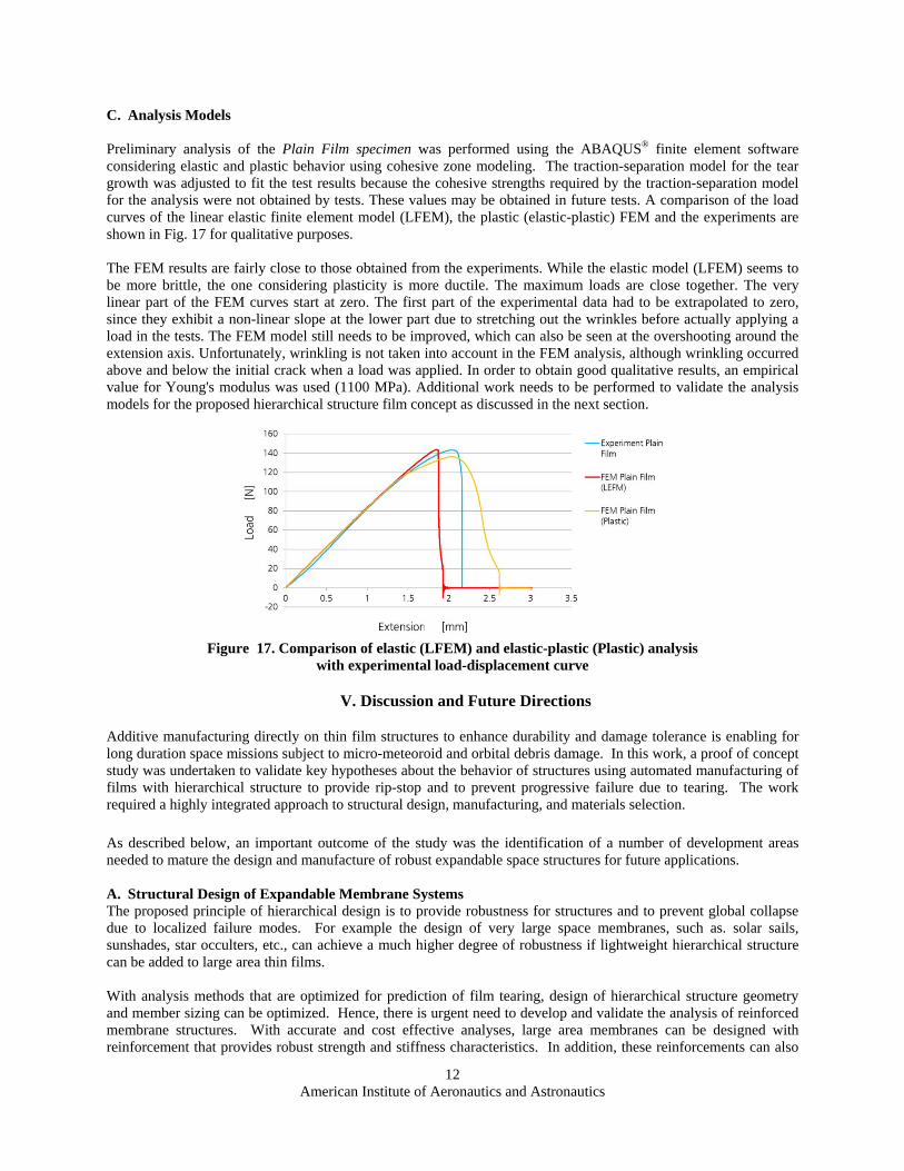
C. Analysis Models Preliminary analysis of the Plain Film specimen was performed using the ABAQUS® finite element software considering elastic and plastic behavior using cohesive zone modeling. The traction-separation model for the tear growth was adjusted to fit the test results because the cohesive strengths required by the traction-separation model for the analysis were not obtained by tests. These values may be obtained in future tests. A comparison of the load curves of the linear elastic finite element model (LFEM), the plastic (elastic-plastic) FEM and the experiments are shown in Fig. 17 for qualitative purposes. The FEM results are fairly close to those obtained from the experiments. While the elastic model (LFEM) seems to be more brittle, the one considering plasticity is more ductile. The maximum loads are close together. The very linear part of the FEM curves start at zero. The first part of the experimental data had to be extrapolated to zero, since they exhibit a non-linear slope at the lower part due to stretching out the wrinkles before actually applying a load in the tests. The FEM model still needs to be improved, which can also be seen at the overshooting around the extension axis. Unfortunately, wrinkling is not taken into account in the FEM analysis, although wrinkling occurred above and below the initial crack when a load was applied. In order to obtain good qualitative results, an empirical value for Young's modulus was used (1100 MPa). Additional work needs to be performed to validate the analysis models for the proposed hierarchical structure film concept as discussed in the next section.
Figure 17. Comparison of elastic (LFEM) and elastic-plastic (Plastic) analysis
with experimental load-displacement curve
V. Discussion and Future Directions
Additive manufacturing directly on thin film structures to enhance durability and damage tolerance is enabling for long duration space missions subject to micro-meteoroid and orbital debris damage. In this work, a proof of concept study was undertaken to validate key hypotheses about the behavior of structures using automated manufacturing of films with hierarchical structure to provide rip-stop and to prevent progressive failure due to tearing. The work required a highly integrated approach to structural design, manufacturing, and materials selection.
As described below, an important outcome of the study was the identification of a number of development areas needed to mature the design and manufacture of robust expandable space structures for future applications.
A. Structural Design of Expandable Membrane Systems The proposed principle of hierarchical design is to provide robustness for structures and to prevent global collapse due to localized failure modes. For example the design of very large space membranes, such as. solar sails, sunshades, star occulters, etc., can achieve a much higher degree of robustness if lightweight hierarchical structure can be added to large area thin films. With analysis methods that are optimized for prediction of film tearing, design of hierarchical structure geometry and member sizing can be optimized. Hence, there is urgent need to develop and validate the analysis of reinforced membrane structures. With accurate and cost effective analyses, large area membranes can be designed with reinforcement that provides robust strength and stiffness characteristics. In addition, these reinforcements can also

American Institute of Aeronautics and Astronautics
13
be used to add multifunctionality to the membrane system. For example, the hierarchical structure reinforcements could also serve as electro-optical pathways throughout the membrane. Another intriguing application of the proposed direct manufacture of hierarchical structure on membranes is to achieve a self deploying membrane. The earwig bug wing (section II) has a fascinating folding and deployment scheme based on just localized areas of elastic strain energy. The degree to which this self-deploying concept can be scaled has not been studied. Self-deploying membranes is another area of research and technology development to reduce the highest mission risk for large space membrane structures, namely, the failure to deploy. B. Additive Manufacturing Additive Manufacturing (AM) is a fast growing technology for both metals and plastics. Near net shape production of metallic parts reduces waste and cost of conventional machining. Until recently, 3-D rapid prototyping machines for production of plastic parts have not been considered for structural applications. However, the widespread accessibility of low cost plastic AM will likely lead to innovative new materials and processes such as fiber reinforcement of the AM parts. Already, small scale AM parts have been fabricated at the 100’s of nanometer scale (Ref. 12). For large scale production, as needed for space structures, the extension of the present study’s direct print on film technology could easily be transferred to a roll-to-roll process as shown in Fig. 18 and described in Ref. 13 for electrospinning of fiber reinforcements. Finally, AM coupled with robotics makes in-space manufacturing of repair parts and of large area structures feasible. Manufacturing in space with plastics, perhaps fiber reinforced, may change the entire concept of packaging and deployment of large space systems.
Figure 18. Roll-to-Roll processing of Rip-Stop Hierarchical Structure
C. Materials Compatibility Current AM compatible plastic materials, e.g. polycarbonate, are not space durable. Polycarbonate, and other AM materials, are mostly selected for the relatively low melt temperature and there rapid solidification. Much work is needed to develop materials compatible with AM technology but also durable in the space environment (atomic oxygen, UV and radiation compatible). In addition, for the proposed direct membrane printing process, the materials must also achieve high bond strength with the membrane material or be integrated within the membrane. Hybrid (composite) materials systems are also feasible with AM. New space durable and AM compatible material systems are critically needed to achieve the potential of polymer based additive manufacturing.

American Institute of Aeronautics and Astronautics
14
VI. Summary
Membrane dominated systems such as solar sails, solar power arrays, antennas, and numerous other large aperture devices suffer from both perceived and real limits in durability and damage tolerance. Fortunately, structural systems can be enhanced by taking a hierarchical approach to design that prevents progressive failure by redistributing loads around a damaged area. In this work, an integrated approach to development of thin-film damage tolerant membranes is explored using advanced manufacturing. A bio-inspired hierarchical structure was “printed” on films using additive manufacturing to achieve improved tear resistance and to facilitate membrane deployment. High precision, robust expandable structures can be realized using materials that are both space durable and processable using additive manufacturing. A fused deposition modeling (FDM) process was used to build lightweight, complex geometries directly on thin films. The rip-stop augmented specimens were tested in tension with simulated MMOD damage by including an initial tear. The tests revealed that such rip-stop structures can stop tear propagation for a certain load and strain. The principle of a hierarchical structure serving as rip-stop was observed with stepped load-displacement curves. Turning or leading a tear could was not observed with the applied test method. The rip-stop test results were analyzed using an FEM model, running elastic as well as elastic-plastic analysis. To date, the analysis has not been adequate for prediction of the steps in the load-displacement curves and needs to be further developed. Test results show this initial work produced higher tear resistance than neat film of equivalent mass, thus validating the premise that an integrated approach that includes material selection, structural design and advanced manufacturing processes can yield enhanced functionality in this class of space structures. Future research and development opportunities are presented for robust expandable structures in the areas of structural design, manufacturing, and materials selection.
References 1 Jenkins, Christopher H.M.: Gossamer Spacecraft: Membrane and Inflatable Structures Technology for Space Applications.
In: Zarchan, Paul: Progess in Astronautics and Aeronautics, Vol. 191, Reston: American Institute of Aeronautics and Astronautics Inc. ,2001
2 Woo, K., Zignego, D. L., and Jenkins, C. H. “Tearing of Thin Sheets with Wrinkling,” AIAA 2011-2089, 52nd AIAA/ASME/ASCE/ASC Structures, Structural Dynamics and Materials Conference, 4-7 April 2011, Denver Colorado.
3 Zignego, D. L., Woo, K. and Jenkins, C. H. “Essential Work of Fracture for Damage Modeling of Polymer Membranes,” AIAA 2011-2085, 52nd AIAA/ASME/ASCE/ASC Structures, Structural Dynamics and Materials Conference, 4-7 April 2011, Denver Colorado. 4 Combes, S. A.; Daniel, T.L.: Flexural stiffness in insect wings II. Spatial distribution and dynamic wing bending. In: The Journal of Experimental Biology, Vol. 206, p. 2989-2997, doi:10.1242/jeb.00524, The Company of Biologists Ltd, 2003
5 Haas, Fabian: Wing Folding In Insects: A Natural, Deployable Structure, 1998. http://www.earwigs-online.de/privat_FH/FH_Cambridge_ 1998.pdf, accessed 10 October 2010.
6 Haas, F.; Gorb, S., Wootton, R.J.: Elastic joints in dermapteran hind wings: materials and wing folding. In: Arthropod Structure & Development, Vol.29, p. 137-146, Elsevier Science Ltd., 2000.
7 Parrish, K., “The JWST Sunshield: A Behind the Scenes Tour of its Engineering Challenges and Design Evolution, Gossamer Forum Keynote Lecture, 50th AIAA/ASME/ASCE/ASC Structures, Structural Dynamics and Materials Conference, 4-7 May 2009, Palm Springs California.
8 U.S. Provisional Patent Application No. 61/431,245 to Belvin et al., “Manufacturing of Low Mass, Large-Scale Hierarchical Thin Film Structural Systems,” filed on January 10, 2011.
9 Zander, M. E., “Development of a Structure Supported Membrane for Deployable Space Applications,” Diplomarbeit, University of Magdeburg, December 2010.
10 Zignego, D. L.: Investigation of Membrane Tearing Characterization and Healing, Master of Science Thesis, Montana State University, Bozeman Montana, 2010. 11Cortet, P. P.; Santucci, S.; Vanel, L.; Ciliberto, S.: Slow crack growth in polycarbonate films. In: Europhysics Letters, Vol.
71, 2005, p. 242-248 12K. Cicha, Z. Li, K. Stadlmann, A. Ovsianikov, R. Markut-Kohl, R. Liska, J. Stampfl: Evaluation of 3D structures fabricated
with two-photon-photopolymerization by using FTIR spectroscopy. Journal of Applied Physics, 110 (2011), 064911; S. 1 - 5. 13M.A. Costolo, J.D. Lennhoff, R. Pawle, E.A. Rietman, A.E. Stevens, "A nonlinear system model for electrospinning sub-
100 nm polyacrylonitrile fibers ," Nanotechnology 19 , 035707 (13 December 2007).