materials science and engineering cmeyersgroup.ucsd.edu/papers/journals/meyers 339.pdf · a...
TRANSCRIPT

Materials Science and Engineering C xxx (2010) xxx–xxx
MSC-02948; No of Pages 6
Contents lists available at ScienceDirect
Materials Science and Engineering C
j ourna l homepage: www.e lsev ie r.com/ locate /msec
Structural characterization and mechanical behavior of a bivalveshell (Saxidomus purpuratus)
Wen Yang a,b, Neima Kashani c, Xiao-Wu Li a, Guang-Ping Zhang b, Marc André Meyers c,⁎a Institute of Materials Physics and Chemistry, College of Sciences, Northeastern University Shenyang 110004, PR Chinab Shenyang National Laboratory for Materials Science, Institute of Metal Research, Chinese Academy of Sciences, 72 Wenhua Road, Shenyang 110016, PR Chinac Department of Mechanical and Aerospace Engineering, Materials Science and Engineering Program, University of California, San Diego, La Jolla, CA 92093-0411, USA
⁎ Corresponding author. Tel.: +1 858 534 4719; fax:E-mail address: [email protected] (M.A. Meyers)
0928-4931/$ – see front matter © 2010 Elsevier B.V. Aldoi:10.1016/j.msec.2010.10.003
Please cite this article as: W. Yang, et al., M
a b s t r a c t
a r t i c l e i n f oArticle history:Received 20 March 2010Received in revised form 24 September 2010Accepted 10 October 2010Available online xxxx
Keywords:BiologicalX-ray diffractionStructureHardnessCompressionShells
The structure and mechanical behavior of Saxidomus purpuratus bivalve shell were investigated. XRD resultsshow that the only form of calcium carbonate present in the shell is aragonite. The inner and middle layershave a cross-lamellar structure, while the outer layer has porosity and does not have tiles, but instead has‘blocky’ regions. The hardness of middle and inner layer are close in both plane view and cross section, but thehardness of outer layer is significantly less, especially in the plane view. The compressive strengths withloading along the three orientations were established and significant differences were found. The Weibullstrength at 50% of the probability of failure varies between 59 and 148 MPa and is dependent on the loadingorientation and in condition of shell (dry vs. hydrated). These differences are interpreted in terms of theanisotropic structure and coarser structure of the external layer.
+1 858 534 5698..
Fig. 1. Fixture used todifferent sizes. Right
l rights reserved.
aterials Science and Engineering C (2010), d
© 2010 Elsevier B.V. All rights reserved.
1. Introduction
Through natural selection over hundreds of millions of years,mollusk shells have developed their structure and mechanicalproperties to protect themselves from attack by a variety of marinepredators, which try to break it using compressive force application,prying attack or nipping attempt. Hence, their properties, consideringthe simple constituents, are much better than man-made materials.The components of biological shells are calcium carbonate which is ingeneral about 95 wt.% and less than 5 wt.% organic materials [1–3].The two principal polymorphs of calcium carbonate in shells arearagonite and calcite. X-ray diffraction (XRD) is usually used to detectthe detailed structure of these minerals. In 1960, Lutts et al. [4]identified the calcium carbonate phases for 19mollusk shells. In 1963,Wilbur and Watabe [5] studied the regeneration process with somemollusk species and found that the crystalline phase in some specieswas not changed during regeneration. Calcium carbonate changedfrom the amorphous state to aragonite during the growth of the shells.Calcite traces were only detected in some organisms [6]. Investigatorsanalyzed the CaCO3 polymorphs in different kinds of shells withdifferent treatments [7–15]. Most of the shells contain aragonite.Some species have both aragonite and calcite, such as Pecten maximus,that contains aragonite and calcite in a proportion of 3:7. The external
layer in abalone is also calcitic. Paula and Silveira [16] summarized theanalytical methods including XRD method. The different CaCO3
polymorphs can form different types of morphologies, such asprismatic structure, sheet nacreous structure, lenticular nacreousstructure, foliated structure, cross-lamellar structure, complex cross-lamellar structure and homogeneous structure [17,18].
These structures, with simple components, can result in outstand-ing properties, such as flexure strength and toughness. The compres-sion strengths of a significant number of shell species have already
prepare the specimens. Left and middle: separate components for: assembled fixture.
oi:10.1016/j.msec.2010.10.003

Fig. 2. XRD results of inner (bottom), middle and outer (top) layers of Saxidomuspurpuratus shell. All the layers are aragonite. Outer layer has more peaks than inner andmiddle layers.
Fig. 3. Cross sections parallel and perpendicular to growth lines of Saxidomuspurpuratus shell and the orientations of compression specimens: Orientation A, loadingperpendicular to the shell surface; Orientation B, loading parallel to the shell surfaceand growth lines; Orientation C, loading parallel to the shell surface and perpendicularto the growth lines.
2 W. Yang et al. / Materials Science and Engineering C xxx (2010) xxx–xxx
been investigated [1,17–25]. The high strength and good toughness ofshells were first identified by Currey and Taylor [1,18–20]. Theyattested that the strongest shells had nearly twice the compressivestrength of bone. Although the flexure strength of shells with somestructures, such as homogeneous structure, is not as high as that ofbone, the compression strengths of shells can be much higher thanbone [17]. Bone has a compression strength of between 88 and232 MPa and a tension strength between 80 and 138 MPa[17,26].
Menig et al. [21,22] investigated the quasi-static and dynamicmechanical response ofHaliotis rufescens and Strombus gigas including
Table 1Calcium carbonate polymorphs of different shells with different state and treatments. (A:aragonite, C: calcite).
Organisms Statetested
Treatment Mineral Ref
Gastropoda Haliotis rufescens Powder R.T. A 13,14Powder 500 °C,
10 minA→C 14
Stromubus gigas Bulk/powder
A 8,9,11
Pomacea canaliculataLamarck
Powder Unannealed A 12
Annealed,N400 °C
A→C 12
Annealed,500 °C
C 12
Annealed,900 °C
CaO 12
Trochus maculates Powder A 13“Flat pearl” (nacreous,block-like, spheruliticlayer)
Planeview
A 7
“Flat pearl” (prismaticlayer)
Planeview
C 7
Bivalve Tridacna gigas Bulk A 9Meretrix lusoria Powder/
bulkA 10, 13
Preria penguin Powder/bulk
A 10, 13
Pecten maximus Powder A(30%)+C 13Tellinella asperrima Powder/
nacreA 15
Saxidomus purpuratus Inner/middle/outerlayers
A Presentwork
Please cite this article as: W. Yang, et al., Materials Science and Engine
compression and analyzed the results by Weibull statistics. Theyshowed that the quasi-static compression strength (measured asfailure probability of 50% [P(V)=0.5] ) of abalone and conch are540 MPa and 166 MPa respectively for loading perpendicular to theshell surfaces; and 235 MPa and 310 MPa respectively for loadingparallel to the shell surfaces. Lin et al. [23] later investigated themechanical properties of a clam called Tridacna gigas and comparedthe results with those obtained by Menig et al. [21,22]. They foundthat the compression strength of red abalone (Haliotis rufescens) isabout twice as that of clam (Tridacna gigas) and four times as that ofconch (Strombus gigas). This difference is the direct consequence ofthe much lower fraction of the mineral component in bone:approximately 0.3 to 0.6 on a volume basis.
Herein, the structure of Saxidomus purpuratus shells was charac-terized by X-ray diffraction and scanning electron microscopy (SEM),and some mechanical properties including hardness and compressionbehavior were investigated.
Fig. 4. Overall view of the cross section perpendicular to the growth lines.
ering C (2010), doi:10.1016/j.msec.2010.10.003
3W. Yang et al. / Materials Science and Engineering C xxx (2010) xxx–xxx
2. Experimental techniques
The Saxidomus purpuratus shells, which are bivalves and like to livein groups in thewater rich with diatom foods, were collected from Bo/Huang Sea Area near Dalian city in China. This kind of shell was chosenbecause its thickness is sufficient so that the specimens can beprepared in different orientations. They were cleaned carefully anddried in air at room temperature. Specimens were cut with a water-cooled low-speed diamond saw. The specimens used in XRD test, OMobservation and hardness testing were ground with sand paper from400# to 2000# and polished carefully to decrease the size and thenumber of the microcracks.
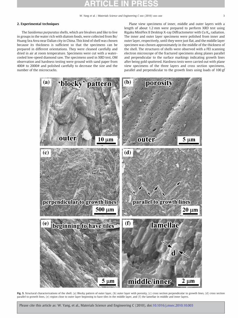
Fig. 5. Structural characterizations of the shell. (a) Blocky pattern of outer layer, (b) outerparallel to growth lines, (e) region close to outer layer beginning to have tiles in the middl
Please cite this article as: W. Yang, et al., Materials Science and Engine
Plane view specimens of inner, middle and outer layers with alength of about 1.2 mm were prepared to perform XRD test usingRigakuMiniFlex II Desktop X-ray Diffractometer with Cu Kα radiation.The inner and outer layer specimens were polished from inner andouter layer, respectively, until theywere just flat, and themiddle layerspecimen was chosen approximately in the middle of the thickness ofthe shell. The structures of shells were observed with a FEI scanningelectron microscope of the fractured specimens along planes paralleland perpendicular to the surface markings indicating growth linesafter being gold sputtered. Hardness tests were carried out with planeview specimens of the three layers and cross section specimens,parallel and perpendicular to the growth lines using loads of 100 gf
layer with porosity, (c) cross section perpendicular to growth lines, (d) cross sectione layer, and (f) the lamellae in middle and inner layers.
ering C (2010), doi:10.1016/j.msec.2010.10.003

Fig. 6. Hardness across cross sections parallel and perpendicular to the growth lines(GL) as a function of the normalized position (x=0.0–1.0) from outer to inner layer;loads of (a) 100 gf and (b) 200 gf. Hardness along plane view (taken in the positions).
4 W. Yang et al. / Materials Science and Engineering C xxx (2010) xxx–xxx
and 200 gf with a Leco M-400-H1 hardness testing machine. Theindentations were separated sufficiently to ensure that the indenta-tion regions would not affect the adjacent regions. Dry and wetcompression specimens with approximate dimensions of3.5×3.5×3.5 mm were prepared in three orientations: loadingperpendicular to the shell surface (A), parallel to the shell surfaceand growth lines (B) and parallel to the shell surface but perpendic-ular to the growth lines (C).
Wet (hydrated) compression specimens were prepared with aspecial fixture to ensure that the two surfaces of the specimens loadedwere flat and parallel (Fig. 1). The shells for these tests were about3–8 mm thick. This thickness allowed the samples to be polished untiltheir edges where parallel, eliminating the irregularities and non-parallelism in their surfaces. The diamond blade cuts were madewithout removing the specimen from the grips to ensure parallelismof the surfaces being tested. A thin sheet of plastic and grease wereused tominimize stress concentrations of the contact regions with theplatens. All the compression specimens were tested under constantloading rate of 1×10⁻³ s−1 in an Instron 3367 testing machine.
3. Results and discussion
3.1. Structural characterization
Fig. 2 shows the XRD patterns obtained from the inner, middle andouter layers of the shells. The intensity and d spacings of the labeledpeaks of the three layers correspond to the 2θ angles of XRD peaks ofaragonite. The inner layer shows a distinct texture. The intensities of the(012), (102) and (113) reflections are much stronger than otherreflections. Themiddle layer shows a similar peak intensity distributionas the inner layer, but its (102)peak is not as strongas that of inner layer.However, the outer layer shows more XRD peaks than the others. Asmost of themollusk shells, themain CaCO3 configuration existing in theshell is aragonite. Table 1 shows calcium carbonate polymorphs fordifferent shells. Only a few shells, such as Pecten maximus [13]¸ containboth aragonite and calcite. When heated to a temperature of about400 °C or 500 °C, the structure of the shells changes from aragonite tocalcite. This transformation occurs because aragonite is a thermody-namically unstable phase of calcium carbonate which exists stably withthe present of organic compound at room temperature [27].
Fig. 3 shows the cross-sectional morphologies parallel andperpendicular to the growth lines of the shell and the threeorientations of the compression specimens with loads. The dashedlines on the little cubes stand for the growth lines. The OM picturesshow an alternation of light and dark layers. The light region is theouter layer. The layers in the cross section parallel to the growth linescorrespond to the shape of shell in that part. The layers in the crosssection perpendicular to the growth lines taken from the edge of shellshow an outward curvature. In the edge of the shell, the inner layersare parallel to each other and follow the shape of shell, but when theyreach the outer layer, they bend toward the surface of the shell. Theselayers represent the growth sequence in the shell, as it increases inboth size and thickness.
The detailed structure of the shell is seen in Fig. 4 (SEM), whichshows the whole view of the cross section perpendicular to thegrowth lines. The approximate ranges of outer, middle, and innerlayers are shown in the picture. Higher magnification was used todistinguish the differences between the structures of three layers.Fig. 5(a) shows the ‘blocky’ pattern of the outer layer and its detailedporous structure is shown in Fig. 5(b); as one goes toward the middlelayer, the structure begins gradually to have tiles. The middle andinner layers have similar crossed-lamellar structure. Fig. 5(c) and(d) shows the morphologies of the cross section perpendicular andparallel to the growth lines, respectively. The orientations of thelamellae are pointed by arrows. Fig. 5(e) shows parallel arrays of tiles(lamellae) in the transition region. Fig. 5(f) shows the lamellae in the
Please cite this article as: W. Yang, et al., Materials Science and Engine
middle and inner layer whose average thickness, d, of about 250 nm.The thickness of these tiles (lamellae) is lower than that of the abalone(~450 nm) [21] and of the bivalve Araguaia shell (~1500 nm). [28].
3.2. Mechanical properties
The hardness was measured with five measurements in the planeview and one measurement in the cross sections. This was done toestablish whether it changes from outer to inner portions of the shellboth parallel and perpendicular to the growth lines. The length of thediagonal of the indentation is about 25–75 μm. The corners of someindentation were damaged or broken. Some cracks spread aroundfrom the tip of the indentation, and someweak lamellae are lost in thecorner by the load. The hardness is calculated by the equation [29],
HV =2P sinðα= 2Þ
d2=
1:8544Pd2
ð1Þ
in which P is the applied load (in kgf), d is the average length of thediagonals (inmm) andα is the angle between the opposite surfaces ofthe indenter (136°). The results are shown in Fig. 6(a) and (b),respectively. The horizontal coordinate represents the normalizeddistance from outer layer to inner layer, and the Y coordinaterepresents the hardness. The variation in hardness is more distinctunder loading of 100 gf. One can see the trend of the hardness in the
ering C (2010), doi:10.1016/j.msec.2010.10.003

5W. Yang et al. / Materials Science and Engineering C xxx (2010) xxx–xxx
cross section from the outer layer to inner layer in Fig. 6(a). Amongthe three layers in the cross section, the hardness of outer layer islowest but varies greatly. The hardness of cross section perpendicularto the growth lines varies more than that of cross section parallel tothe growth lines. The hardness of plane view layers is easier toevaluate under the load of 200 gf, and is shown in Fig. 6(b). Thehardness (plane view) of outer layer (~1200 MPa) is considerablylower than those of middle (~2400 MPa) and inner layer(~2700 MPa) due to their different structures and porosities.
The compression strengths were obtained from about 10 speci-mens in each orientation and analyzed by theWeibull method and areshown in Fig. 7. The specimens in Orientation A are much harder toobtain because the shell was too thin in some areas for a 3.5 mmspecimen to be made from it. A typical stress-strain plot tested inOrientation B is shown in Fig. 7(a). The compression strength andmodulus are 88.3 MPa and 11.9 GPa, respectively. The two drops inload (marked by arrows) indicate that the cracks that formed wereoften of the ‘axial splitting’ kind and the specimens were not damagedcatastrophically. Fig. 7(b)–(d) shows the compression strengths fittedwith Weibull curves for Orientations A, B and C, respectively. Theseorientations are defined in Section 2. As seen above, the hardness inOrientation C is the highest, while the hardness in Orientation A is thelowest. The compression strengths obtained with dry/wet specimens(50% of the probability of failure) are 101.6/109.8 MPa and 101.8/148.0 MPa in Orientations B and C, respectively, while the one for
Fig. 7. Compression test results; (a) a typical stress-strain plot obtained in Orientation B; (b)wet specimens in Orientations B and C, respectively.
Please cite this article as: W. Yang, et al., Materials Science and Engine
Orientation A is lower (58.8/105.0 MPa). The strength in OrientationsA and C for dry differ considerably from the strength for wet in thesame orientations, respectively. This is well known for shells and hasbeen attributed to the effect of hydration on the mechanicalproperties of the organic interlayer. The Weibull modulus, whichdepends on the distribution of flaw sizes [30,31], is a measure of thevariability of strength. The higher the value of m, the less thevariability of the material strength is [29]. So, there is less variation inthe compression strengths in Orientations B (m=4.81, 2.21) and C(m=4.42, 3.93) than in Orientation A (m=2.67, 2.36). This indicatesthat mechanical properties of the shell are anisotropic. One possiblereason for the difference is that the compressive specimensincorporate both the external and internal regions, which havedifferent strengths. When loading is applied perpendicular to thesurface, the two components are in series and the strength of theweakest component (the outside layer) determines the strength ofthe specimen. On the other hand, when loading is applied in the planeof the shell, the two components are in parallel and subjected to thesame stress. The strongest (middle and inner layers) can carry load toa higher level than the outside, and the specimens are consequentlystronger. The compressive strengths of the Araguaia bivalve shells[28] (the strongest in compression studied by our group) were567 MPa perpendicular and 347 MPa parallel to surface. Hence,Saxidomus purpuratus is also much weaker than the shells previouslymentioned, such as abalone and conch [21,22]. This can be attributed
Weibull fit of dry and wet specimens in Orientation A; and (c, d) Weibull fit of dry and
ering C (2010), doi:10.1016/j.msec.2010.10.003

6 W. Yang et al. / Materials Science and Engineering C xxx (2010) xxx–xxx
to a lower fraction of organic material in the structure of theSaxidomus shell.
4. Conclusions
The structure of Saxidomus purpuratus shells was analyzed by XRD,OM and SEM. The mechanical properties were investigated throughhardness and compression tests. The calcium carbonate exists inaragonite structure in the three layers. The outer layer has a porousblocky structure, while the middle and inner layers have a cross-lamellar structure with distinct XRD patterns. The hardness in planeview of the outer layer is much lower than that of the inner andmiddle layer and varies considerably in the cross sections, bothperpendicular and parallel to the growth lines. The hardness of middleand inner layers show less variability than that of the outer layer. Thecompression strength with loading perpendicular to the surface of theshell is the lowest and shows the greatest variation. Because thecomponent with the lowest strength (outside) fails first and itsstrength determines the overall strength. For the other two loadingdirections, the interface is parallel to the loading direction and the tworegions act as springs in parallel. The strengths vary betweenapproximately ~50 and 150 MPa, which is much lower than shellspreviously studied by our group. These ranged from ~160 to~550 MPa [21–23,28].
Acknowledgements
This work was supported by NSF DMR Biomaterials Program atUCSD. We thank the following persons that have contributedsignificantly to this work: C.T. Wei, for assisting with mechanicaltesting and XRD, Y.S. Lin, for assisting with the hardness testing, J.Kiang, for assisting with the compression tests, A. Suwarnasarn, forhelping with SEM observation, M.L. Li and Y. Li, for helping with
Please cite this article as: W. Yang, et al., Materials Science and Engine
interpretation of the XRD results. P.Y. Chen and I.H. Chen helped withseveral aspects of the research.
References
[1] J.D. Currey, Proc. R. Soc. Lond. 196 (1977) 443.[2] K. Okumura, P.G. Gennes, Eur. Phys. J. E 4 (2001) 121.[3] G. Kramptz, G. Graser, Science 255 (1992) 1098.[4] A. Lutt, J. Grandjean, Ch. Grégorie, Arch. Int. Physiol. Biochim. 68 (1960) 829.[5] K.M. Wilbur, N. Watabe, Ann. NY Acad. Sci. 109 (1963) 82.[6] D. Medakovié, S. Popovié, B. Grzeta, M. Plazonié, M. Hrs-Brenko, Mar. Biol. 129
(1997) 615.[7] X.W. Su, A.M. Belcher, C.M. Zaremba, D.E. Morse, G..D. Stucky, A.H. Heuer, Chem.
Mater. 14 (2002) 3106.[8] X.W. Su, D.M. Zhang, A.H. Heuer, Chem. Mater. 16 (2004) 581.[9] X. Zhang, K.S. Vecchio, Mater. Sci. Eng. C 26 (2006) 1445.
[10] Z.H. Zhu, H. Tong, Y.Y. Ren, J.M. Hu, Micron 37 (2006) 35.[11] K.S. Vecchio, X. Zhang, J.B. Massie, M. Wang, C.W. Kim, Acta Biomater. 3 (2007)
910.[12] N. Udomkan, P. Limsuwan, Mater. Sci. Eng. C 28 (2008) 316.[13] F.D. Fleischli, M. Dietiker, C. Borgia, R. Spolenak, Acta Biomater. 4 (2008) 1694.[14] Z.W. Huang, X.D. Li, Mater. Sci. Eng. C 29 (2009) 1803.[15] F.Z. Ren, X.D. Wan, Z.H. Ma, J.H. Su, Mater. Chem. Phys. 114 (2009) 367.[16] S.M. de Paula, M. Silveira, Micron 40 (2009) 669.[17] J.D. Taylor, M. Layman, Palaeontology 15 (1972) 73.[18] J.D. Currey, J.D. Taylor, J. Zool. Lond. 173 (1974) 395.[19] J.D. Currey, J. Zool. 180 (1976) 445.[20] J.D. Currey, Biorheology 2 (1964) 1.[21] R. Menig, M.H. Meyers, M.A. Meyers, K.S. Vecchio, Acta Mater. 48 (2000) 2383.[22] R. Menig, M.H. Meyers, M.A. Meyers, K.S. Vecchio, Mater. Sci. Eng. A 297 (2001)
203.[23] A.Y.M. Lin, M.A. Meyers, K.S. Vecchio, Mater. Sci. Eng. C 26 (2006) 1380.[24] R.Z. Wang, Z. Suo, A.G. Evans, N. Yao, I.A. Aksay, J. Mater. Res. 16 (2001) 2485.[25] F. Barthelat, H. Tang, P.D. Zavattieri, C.M. Li, H.D. Espinosa, J. Mech. Phys. Solids 55
(2007) 306.[26] J.D. Currey, Clin. Orthop. 73 (1970) 210.[27] S. Weiner, L. Addadi, Trends Biochem. Sci. 16 (1991) 252.[28] P.-Y. Chen, A.Y.M. Lin, Y.-S. Lin, Y. Seki, A.G. Stokes, J. Peyras, E.A. Olevsky, M.A.
Meyers, J. McKittrick, J. Mech. Behav. Biomed. Mater. 1 (2008) 208.[29] M.A. Meyers, K.K. Chawla, Mechanical behavior of materials, Prentice-Hall, USA,
1999.[30] A.D.S. Jayatilaka, K. Trustrum, J. Mater. Sci. 12 (1977) 1426.[31] R. Danzer, J. Eur. Ceram. Soc. 10 (1992) 461.
ering C (2010), doi:10.1016/j.msec.2010.10.003