materials & design - accedacris
TRANSCRIPT

Materials & Design 206 (2021) 109758
Contents lists available at ScienceDirect
Materials & Design
journal homepage: www.elsevier .com/locate /matdes
Biomechanical characterization of custom-made dynamic implantsfabricated by Electron Beam Melting for anterior chest wallreconstruction
https://doi.org/10.1016/j.matdes.2021.1097580264-1275/� 2021 The Authors. Published by Elsevier Ltd.This is an open access article under the CC BY-NC-ND license (http://creativecommons.org/licenses/by-nc-nd/4.0/).
⇑ Corresponding author at: Edificio de Ingenierías, Campus Universitario deTafira, 35017 Las Palmas de Gran Canaria, Las Palmas (Canary Islands), Spain.
E-mail address: [email protected] (M.P. Fiorucci).
María Paula Fiorucci a,⇑, Alberto Cuadrado a, Alejandro Yánez a, Oscar Martel a, Belinda Mentado b,c,Donato Monopoli b,c
aDepartment of Mechanical Engineering, University of Las Palmas de Gran Canaria, 35017 Las Palmas de Gran Canaria, SpainbDepartment of Biomedical Engineering, Technological Institute of the Canary Islands (ITC), 35118 Arinaga, SpaincOsteobionix S.L, 35118 Arinaga, Spain
a r t i c l e i n f o
Article history:Received 4 November 2020Revised 24 March 2021Accepted 20 April 2021Available online 22 April 2021
Keywords:Custom-made dynamic implantElectron Beam MeltingBiomechanical analysisTi-6Al-4VChest wall reconstruction
a b s t r a c t
Large thoracic defects need to be reconstructed to restore inner organs protection and normal ventilation.Early rigid implants have provided the stabilization of the ribcage; however, those have been associatedwith breathing restrictions. The evolution of additive manufacturing has enabled the production of 3Dcustom-made thoracic implants. This has led to case reports on reconstructions with these prostheses,particularly for large anterior resections. A novel design of thoracic implant with dynamic capacity hasalready been reported, with promising short-term outcomes. However, specific biomechanical studiesare needed to clarify its mechanical behaviour. A study of the evolution of the design of dynamic thoracicimplants was carried out and such implants were biomechanically tested. Furthermore, finite elementanalyses were carried out to obtain a simple and reliable model to predict the implant behaviour, consid-ering a rib and its costal cartilage. In the models, the stiffness and stress distribution along the implantand the bone showed that the reconstructions exhibited adequate mechanical behaviour. One of thedesigns provided a flexibility that closely matched the native model and the maximum stress valuesdid not exceed the 30% of the yield strength of Ti-6Al-4V. The implants strength was demonstrated tobe sufficient under tested conditions.� 2021 The Authors. Published by Elsevier Ltd. This is anopenaccess article under the CCBY-NC-ND license
(http://creativecommons.org/licenses/by-nc-nd/4.0/).
1. Introduction
Chest wall defects generally result from resection of primarychest wall tumours, locally-invasive malignancies or metastaticlesions, radiation injury, infection, or trauma [1,2]. The primarygoals of chest wall reconstruction include the restoration of thechest wall rigidity (skeletal stability) to protect intrathoracicorgans and to preserve the mechanics of breathing [2,3]. In com-plex cases, large resection may be required, with more than onerib and several anatomical structures, such as cartilages and thesternum, also needed to be removed.
Reconstruction of the chest wall remains controversial regard-ing the technique to be applied and the type of material or implantto be used [4]. The location and the size of the defect to be recon-structed are principal aspects to take into consideration [3]. Several
reconstructive materials have been proposed, including rigid andsoft materials, with or without soft tissue covering, such astitanium-based osteosynthesis systems, acrylic or methylmethacrylate resins, cryopreserved allografts, titanium micromeshsandwiched between a layer of polyethylene mesh, or muscularflaps [5].
The progress in the Additive Manufacturing (AM) technologyhas enabled the production of custom-made implants for chestwall reconstructions. Computed Tomography (CT) data of thepatient allow the development of an implant model that com-pletely fulfils the patient’s anatomy, based on a precise locationand size of the chest wall resection. Demondion et al. [6] fabricateda Ti-6Al-4V sternum which was composed of a plate connected tothree staples on each side drawn to be tightened on several ribs.Turna et al. [7] manufactured a single Ti-6Al-4V plate by SelectiveLaser Melting (SLM) with the shape of the sternum, the clavicles,the first three ribs on the left side and the first four ribs on the rightside. Both implants focused mainly on a rigid and static anatomicalreconstruction that did not take into account the elongation of the

María Paula Fiorucci, A. Cuadrado, A. Yánez et al. Materials & Design 206 (2021) 109758
removed cartilages and the anterior thoracic joints. Anotherimplant design incorporated a rigid sternal core with titanium rodsas neo-ribs to improve the flexibility of the implant fabricated byElectron Beam Melting (EBM) in titanium alloy [8].
In recent years, there has been a growing number of publica-tions of case reports on reconstructions with 3D thoracic implants[9–13]. Although rigid methods ensure stabilization of skeletal ele-ments of the chest for breathing balance [14], they are associatedwith difficulty to anatomical fitting, implant migration, dislocation,infection and failure [2,15]. The lack of implant flexibility woulddifficult following breathing movements of the thorax and mightcause patient discomfort during ventilation. Respiratory complica-tions have been reported as the main source of morbidity afterchest wall reconstruction [16,17].
A novel design of custom thoracic implant has been recentlyoriginated. The design was adapted to mimic the mechanical beha-viour of the tissues to be replaced along with chest reconstruction:an equivalent region of the ribcage formed by cartilage and rib,including the sternocostal joint. A dynamic concept was intro-duced by a ground-breaking design with a spring-like geometrywhich makes the implant flexible. The implants have been fabri-cated by EBM and SLM from Ti-6Al-4V powder and have been clin-ically tested in singular patients who required large anterior chestwall resection [18–21]. According to some postoperative dynamicstudies, the novel design has proven to be able to mimic the beha-viour of the natural chest wall during ventilation and to maintainan adequate respiratory function [19,20]. Those previous clinicalresults give promising evidence that the novel spring-like implantis an optimal choice for reconstructive application in wide anteriorchest wall resection. Although clinical reports have described thenovel surgical procedure and patient short-term outcomes, morepatient cases, long-term clinical follow-up, as well as specificbiomechanics studies, are still required.
Overall, the ideal implant should restore the native stiffness ofthe ribcage and be sufficiently flexible to accommodate breathing.In general, anterior chest wall reconstruction requires variableimplantable solutions, including total, partial or no sternum struc-ture associated with one or several cartilage-ribs. To advance safelyin the use of customized devices, it is imperative to investigate intoa harmless implant design and to clarify the mechanical character-istics that thoracic implants must have.
The main goal of this study is to present the rationale of thedesign and the biomechanical characterization of a previouslyreported dynamic thoracic implant in anterior chest wall recon-struction. Based on the presented grounds, in this study it is sug-gested that the mechanical properties of a 3D printed thoracicimplant can be enhanced by optimizing the design of the implant,in terms of flexibility and strength. In the present work, thedynamic implant structures were tested by means of experimentaland Finite Element (FE) studies.
2. Materials and methods
2.1. Design and manufacturing of thoracic implants
The original idea of the design made to obtain dynamic implantsstarted with a simple wavy pattern design resembling a spring-likeshape device. Hence, the first design approach was based on a wavyshape andwas designated as sample S0 (Fig. 1a). In order to estimatethe general mechanical behaviour of S0, an arbitrary range of thick-ness (T) was selected. The thickness range was [1.6; 2; 2.7; 3.4; 4.1]mm and the width (W) was 13 mm.
Based on the results of the preliminary testing (detailed below),new typologies were designed to improve the folding pattern. Oneof the samples, named S1, was designed with variable T andW. The
2
centre of S1 had T = 2.5 mm and W = 14 mm, continuously growinguntil reaching ends of T = 2.7 mm and W = 15 mm (Fig. 1b). A thirdsample was designed (S2), introducing a variation in folding formby rolling it up in a longitudinal axis which resulted in a tubular-like shape. S1 and S2 had the same T and W gradients towardsthe extremities (Fig. 1c).
The additive manufacturing of the implants was done by EBMdeveloped by Arcam AB (Krokslätts Fabriker, Mölndal, Sweden)from Ti-6Al-4V-ELI powder (with an average diameter of 50 lm,ARCAM AB). The fabrication procedure was on a stainless-steelstart plate and the working parameters were set to generate melt-ing layers of 70 mm. The process was kept under vacuum at 10�3
mbar, controlled by Helium. A constant temperature of 700 �Cwas maintained inside the vacuum chamber throughout the fabri-cation. Post-processing of the implants was carried out by remov-ing the fabrication supports and mechanical polishing of thesurface because of the high roughness of the EBM fabrication [22].
2.2. Experimental tests
Quasi-static three-point bending tests were carried out. Aservo-mechanical testing machine was used for bending tests,according to ASTM standards F 382–99 and ISO 9585. A customizedsemi-circular head was built to adapt the servo actuator to achievea distributed load on the implants (Fig. 2a). The actuator displace-ment velocity was 2 mm/min and the load was applied until fail-ure. The 3D implants were fabricated embedded into supportswhich maintained both ends of the samples fixed (fixed–fixedcondition).
The curves of force versus displacement were obtained. Thestructural stiffness of each specimen was obtained as the slope ofthe linear part of each force–displacement curve.
2.3. Finite element models
The proposed methodology for the FE analyses is presented inthree stages. The FE software used was Abaqus 6.14–2 (DassaultSystem, SIMULIACorp., Providence, RI, USA).
The first FE analysis was performed on the CAD models of thethreedesignsof the implants (S0, S1 and S2) to conduct abiomechan-ical analysis of the thoracic implants. A replica of experimentalthree-point bending tests was carried out by FE models. An elasticmodulusof93GPaandaPoisson’s ratioof0.3wasapplied to theelas-tic model and a yield stress of 869MPa was applied to the plasticitymodel [23–25]. To simulate the boundary conditions of the three-point bending tests, the ends of the samples were fixed, and a dis-placement of 25mmwas applied through the cross-head of the test-ing machine. This part was considered as having infinite stiffnessbecause it did not affect the computational study. The contactbetween the cross-head and the samples was a frictionlesssurface-to-surface interaction (Fig. 2b). After conducting the rele-vant sensitivity tests, the type of element selected for the meshwas a ten-node tetrahedral element (C3D10). Estimation of stiffnessand von Mises stress distribution of the implants were obtained.
The second computational analysis was focused on the develop-ment of an anatomical model of the sub-structural level of the ribc-age, i.e. a semi rib-ring of the thoracic cage. For that purpose, fromthe CT scan of a complete thorax obtained from a healthy malesubject, the third right rib and its costal cartilage were isolatedfrom the sternum to the spine. Only the right segment of the semirib-ring was considered for simplification of analysis [26]. All thejoints were also removed from the analysis. This model wasreferred to as ‘‘the native model”. The STL files from the CT scanwere used for the segmentation and reconstruction with the Sim-pleware commercial package (Synopsys International Ltd., CA,USA). Then, the volumetric meshes were obtained in order to

Fig. 1. Designs of the thoracic implants: a) sample S0; b) sample S1; c) sample S2. The cutting plane (A-A’) and the cross-sectional area A-A’ are represented to indicate thedimensions T and W.
Fig. 2. 3-point bending test. a) Experimental set-up. b) Representation of thecontact between the machine head and the sample (S2) in FE simulations.
María Paula Fiorucci, A. Cuadrado, A. Yánez et al. Materials & Design 206 (2021) 109758
export to Abaqus. The costal cartilage was modelled as a solid seg-ment with a circular cross-section with a length that allowed thecontinuity from rib end to sternum along the anatomicalcircumference.
All tissue behaviours were modelled as isotropic linear elasticmaterials and material properties were obtained from the litera-ture. The cortical rib bone had Young’s modulus (E) and Poison’sratio (m) of 14.4 GPa [27] and 0.3 [28], respectively. The trabecularrib bone had E = 40 MPa and m = 0.35 [28]. The costal cartilage hadan E = 35.8 MPa (average value obtained for the third cartilage) andm = 0.40 [29]. The costal cartilage is a composite structure, formedby a central mid-substance of hyaline cartilage surrounded by afibrous layer, the perichondrium, and those structures exhibiteddifferent local material properties which can affect the overall stiff-ness of the ribcage [29]. Hence, a homogeneous representation of
3
costal cartilage was modelled with an effective E necessary toreproduce the structural behaviour of whole costal cartilage seg-ment [29–31].
A set of loading and boundary conditions were established toanalyse the biomechanical response of the semi rib-ring undersimulated physiological loads and to predict the overall stiffnessof the native model. A simplified loading scenario was reproduced,where the vertebral rib end was articulated and the sternal endwas displaced 10 mm towards the posterior end in the plane whichbest fitted the shape of the cartilage and the rib, to create ananterior-posterior load causing the bending deformation [28]. Asingle rotational degree of freedom, on an axis normal to the load-ing plane, was permitted at the posterior extremity. No movementwas allowed at the costochondral junction [32]. Estimation of stiff-ness and stress distribution were carried out. The described modelcan be observed in Fig. 3a.
The third computational analysis was developed to model thereconstruction of a single right rib with a 3D thoracic implant. Inthis reconstructed model, the cartilage and an anterior portion ofthe rib were removed, and the remaining rib portion was recon-structed with S1 and S2 implant typologies. The rib reconstructedmodel was simulated in the same manner that the previous nativemodel. The material properties of the thoracic implants used in thismodel were the same as in the first FE analysis, whereas the prop-erties of the materials of the rib and the boundary conditions anddisplacement of this third model were the same as in the second FEanalysis (Fig. 3b and 3c). Then, a comparative analysis was per-formed in terms of overall stiffness and stress distribution alongthe bone and the implant.
3. Results
3.1. Experimental tests
The experimental results of the three-point bending test of S0with several thickness values are summarized in Table 1. Maxi-mum values were obtained from the force–deformation curves of

Fig. 3. FE models for a) native condition; b) rib reconstruction with implant S1; and c) rib reconstruction with implant S2.
María Paula Fiorucci, A. Cuadrado, A. Yánez et al. Materials & Design 206 (2021) 109758
the loaded implant until failure. The estimation of the stiffnessparameter is also given.
There was a relationship, although non-proportional, betweenthe stiffness and the amount of material in the implant. Whenthe sample broke, the failure was at the ends in all samples(Fig. 4a).
Regarding implant S2, the experimental results of the three-point bending test showed an average value of peak force and dis-placement before the failure of (218 ± 41.1) N and (19.6 ± 2.4) mm,respectively, given in mean and standard deviation values. Theestimation of the stiffness was (10.1 ± 0.6) N/mm. The failure ofthe samples was observed to occur in regions located betweenthe centre and the ends (Fig. 4b).
3.2. FE analyses of implant designs
The FE studies were performed first on the CAD design ofimplant S0. When S0 was loaded, the maximum stresses occurredat the ends of the sample. Fig. 4c depicts the von Mises stress dis-tribution on the S0 with a thickness of 1.6 mm. A small fraction atthe end of the sample was beyond the elastic limit and was coinci-dent with the failure observed in experimental test.
Analogously, the validation of the FE model for implant S2 wasperformed based on the results of the previous experimental testpresented. Fig. 5 shows the load–displacement curves resultingfrom both studies. Thus, a good agreement between the experi-mental and the FE curves was observed.
Once the S2 FE model was validated, the same set of parameterswere implemented into the FE model based on the CADmodel of S1structure. Then, a comparison between the load–deflectionresponse of the two designed implants was made. Fig. 6 depictsthe FE results for the force versus displacement response in thethree-point bending test. The estimation of stiffness was obtainedfrom the calculation of the slope of the linear regression, which
Table 1Experimental data resulted from the 3-point bending test of the S0 implant withseveral thickness values.
Sample thickness (mm) Force (N) Displacement(mm)
Stiffness(N/mm)
1.6 124 24.19 5.132 419 32.89 12.742.7 804 29.32 27.423.4 811 28.91 28.054.1 820 27.56 29.75
4
showed a high goodness of fit index (R2). The fitting indicated thatthe implants presented different bending stiffness values: 10.0 N/mm for S2 and 13.1 N/mm for S1.
Von Mises stress distribution for implants S1 and S2 wereobtained (Fig. 7). The maximum stress values in S1 were locatedat the ends of the sample and other critical points at the centre.Only the ends exceeded the yield limit. More homogeneous stressdistribution was observed in S2. The maximum von Mises stressvalues were found at smaller points located between the endsand the centre, in consonance with the place where failure wasobserved (Fig. 4d).
3.3. FE analysis of native and reconstructed models
Under the anterior-posterior bending loading simulations in theFE models, a plot of the reaction force at the posterior end of the ribversus deflection applied to the system was obtained for the nativemodel and the reconstruction with implants S1 and S2 (Fig. 8). Thestiffness of the native model was estimated to be 1.13 N/mm. Inthe case of reconstruction with implant S1, the stiffness was2.52 N/mm and for implant S2, the stiffness was 1.70 N/mm.
The analysis of the stress distribution was performed on thesimulated tissues and implants. Fig. 9a depicts the Maximum Prin-cipal stress distribution in simulated tissues of the native model.The data are listed in Table 2. The maximum bone stress reachedwas around 20 MPa in tension (Fig. 9a). An increase in the maxi-mum bone stress value in the range of 22–35 MPa stress wasobserved when the rib was reconstructed and predominantlyoccurred at the same location as in the observed for the nativemodel, i.e. on the external convex region of the body of the rib.When comparing the bone stress outcome generated by the ribreconstruction with implant designs, the S1 reconstruction showedhigher maximum bone stress values than the S2 reconstruction(Table 2, Fig. 9b and c).
In order to clarify the von Mises stress distribution on theimplants, cortical and trabecular bones have been hidden inFig. 10. Different distribution patterns of von Mises stress wereexhibited. Implant S2 showed a more homogeneous stress distribu-tion than S1, and the latter also showed higher stress values occur-ring more frequently. The maximum von Mises stress value forimplant S1 was 328 MPa, whereas for implant S2 it was 248 MPa(Table 2). Those peak values represented the 40% (implant S1)and the 30% (implant S2) of the yield stress value of Ti-6Al-4V fab-ricated by EBM.
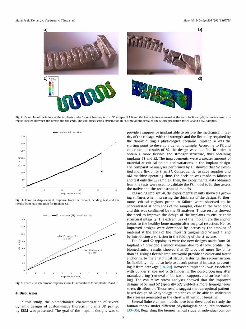
Fig. 4. Examples of the failure of the implants under 3-point bending test. a) S0 sample of 1.6 mm thickness, failure occurred at the ends, b) S2 sample, failure occurred at aregion located between the centre and the ends. The von Mises stress distribution in FE simulations revealed the failure prediction for c) S0 and d) S2 samples.
Fig. 5. Force vs displacement response from the 3-point bending test and theresults from FE simulation for implant S2.
Fig. 6. Force vs displacement responses from FE simulations for implants S2 and S1.
María Paula Fiorucci, A. Cuadrado, A. Yánez et al. Materials & Design 206 (2021) 109758
4. Discussion
In this study, the biomechanical characterization of severaldynamic designs of custom-made thoracic implants 3D printedby EBM was presented. The goal of the implant designs was to
5
provide a supportive implant able to restore the mechanical integ-rity of the ribcage, with the strength and the flexibility required bythe thorax during a physiological scenario. Implant S0 was thestarting point to develop a dynamic sample. According to FE andexperimental results of S0, the design was modified in order toobtain a more flexible and stronger structure, thus obtainingimplants S1 and S2. The improvements were a greater amount ofmaterial at critical points and variations in the implant design.The comparative analyses performed by FE showed that S2 exhib-ited more flexibility than S1. Consequently, to save supplies andAM machine operating time, the decision was made to fabricateand test only the S2 samples. Then, the experimental data obtainedfrom the tests were used to validate the FE model to further assessthe native and the reconstructed models.
Regarding implant S0, the experimental results showed a grow-ing stiffness when increasing the thickness of the design. Further-more, critical regions prone to failure were observed to beconcentrated at both ends of the samples, close to the fixed ends,and this was confirmed by the FE analyses. Those results showedthe need to improve the design of the implants to ensure theirstructural integrity. The extremities of the implant are the anchorpoints to the healthy bone margin after surgical resection. Hence,improved designs were developed by increasing the amount ofmaterial at the ends of the implants (augmented W and T) andby introducing a variation in the folding of the structure.
The S1 and S2 typologies were the new designs made from S0.Implant S1 provided a minor volume due to its low profile. Thebiomechanical results showed that S2 provided more flexibilitythan S1. Using a flexible implant would provide an easier and fasteranchoring to the anatomical structure during the reconstruction.Its flexibility might also help to absorb potential impacts, prevent-ing it from breakage [18–20]. However, implant S2 was associatedwith bulkier shape and with hindering the post-processing aftermanufacturing (removal of fabrication supports and surface finish-ing). The von Mises stress analyses showed that the improveddesigns of S1 and S2 (specially S2) yielded a more homogeneousstress distribution. Those results suggest that an optimal patient-based design of S2 typology implant could be able to withstandthe stresses generated in the chest wall without breaking.
Several finite element models have been developed to study thehuman thorax under different physiological or injured scenarios[33–35]. Regarding the biomechanical study of individual compo-

Fig. 7. The von Mises stress distribution of 3-point bending test for implants S1 and S2 under 25 mm of imposed displacement. The machine head was removed from thepicture to improve visualization.
Fig. 8. Force reaction at the posterior end of the rib versus imposed deflectionunder anterior-posterior loading scenario simulated by FEM for the native andreconstructed models with S1 and S2 implants.
María Paula Fiorucci, A. Cuadrado, A. Yánez et al. Materials & Design 206 (2021) 109758
nents of the thorax, several FE models have studied the structuralresponse and fracture prediction of human ribs [28,36,37] and, to alesser extent, FE models of the costal cartilage [38–40]. However, itwas difficult to find FE models that study the biomechanical beha-viour of semi rib-ring, formed by an individual rib and its costalcartilage. Such models could give support, on the one hand, toidentify the range of mechanical properties ideal for thoracicimplant and, on the other hand, to investigate the mechanical cou-pling of the implant with the rib. Hence, in the present work, thenative model of the third right rib and its cartilage developed fromCT images of a real patient and the reconstructed model with theproposed implants were studied. The structural stiffness of thenative model obtained for the anterior-posterior bending waslower (1.13 N/mm) than values reported for individual ribs in theliterature, because the inclusion of the costal cartilage segmentin the analysis leads to a decrease in the stiffness of the model.The individual rib stiffness has been reported in the literature[28,41–43]. When the segment of costal cartilage is considered,
6
an accurate model can be assembled, being this model sensitiveto E variation of the cartilage as it has been reported by otherauthors [30,38]. An increased range of E from 20 to 66 MPa hasbeen reported as a result of high calcification of the cartilage[40]. As it was shown, by changing the design and its parameters,different stiffness values of the implant can be achieved. Particu-larly, large anterior chest wall reconstruction still represents achallenge to thoracic surgery since a single implant is required toreplace ribs, several costal cartilage segments and even the ster-num, either partially or completely.
The results of FE simulations of the reconstructed models pre-sented in this study showed that the stiffness of the implant andrib reconstructed mode was slightly higher than that of the nativemodel. Although the estimated stiffness for both models was sim-ilar, the reconstruction with S2 provided the flexibility thatmatched closer to the native model. A yield stress reference valuefor cortical bone in the range from 65.3 to 100.7 MPa could be con-sidered [28,33,37]. Despite an increment in the maximum princi-pal stress at the bone with regard to the native model, peakstress values are still far below the referenced strength range, rep-resented by approximately the 42% and 26% of the mean corticalyield stress reference, respectively for implants S1 and S2. The pat-tern of stress distribution remains still the same on the rib bone.Thus, the reconstruction with the proposed implant would notinduce stress concentration that could be harmful or induce furtherinjury at the rib.
Regarding von Mises stress distribution at the implants, themaximum stress reached the 40% for implant S1 and the 30% forimplant S2 of the yield strength value of Ti-6Al-4V fabricated byEBM. Under the loading scenario and boundary conditions tested,there are no induced maximal stresses that might damage theimplant or the rib bone. To date, few studies have focused on themechanical properties of custom-made thoracic implant manufac-tured by AM techniques. Due to variations in implant designs, fab-rication material, loading condition, etc., comparing results amongstudies is not always possible. The PEEK rib implant reported byKang et al. [44] showed that its stiffness was lower than that of
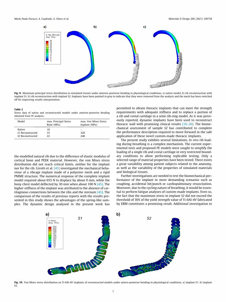
Fig. 9. Maximum principal stress distribution in simulated tissues under anterior-posterior bending in physiological conditions, a) native model, b) rib reconstruction withimplant S1, b) rib reconstruction with implant S2. Implants have been painted in grey to indicate that they were removed from the analysis and the mesh has been switchedoff for improving results interpretation.
Table 2Stress data of native and reconstructed models under anterior-posterior bendingobtained from FE analysis.
Model max. Principal StressBone (MPa)
max. Von Mises StressImplant (MPa)
Native 18 –S1 Reconstructed 35 328S2 Reconstructed 22 248
María Paula Fiorucci, A. Cuadrado, A. Yánez et al. Materials & Design 206 (2021) 109758
the modelled natural rib due to the difference of elastic modulus ofcortical bone and PEEK material. However, the von Mises stressdistribution did not reach critical limits, neither for the implantnor for the rib. Girotti et al. [45] investigated the mechanical beha-viour of a ribcage implant made of a polyester mesh and a rigidPMME structure. The numerical response of the complete implantmodel required about 655 N to displace by about 9 mm, while thebony chest model deflected by 30 mm when about 100 N [45]. Thehigher stiffness of the implant was attributed to the absence of car-tilaginous connections between the ribs and the sternum [45]. Thecomparison of the results of previous reports with the results pre-sented in this study shows the advantages of the spring-like sam-ples. The dynamic design analysed in the present work has
Fig. 10. Von Mises stress distribution on Ti-6Al-4V implants of reconstructed models unS2.
7
permitted to obtain thoracic implants that can meet the strengthrequirements with adequate stiffness and to replace a portion ofa rib and costal cartilage in a semi rib-ring model. As it was previ-ously reported, dynamic implants have been used to reconstructthoracic wall with promising clinical results [18–20]. The biome-chanical assessment of sample S2 has contributed to completethe performance description required to move forward in the safeapplication of these novel custom-made thoracic implants.
The present study exhibits several limitations. In vivo rib load-ing during breathing is a complex mechanism. The current exper-imental tests and proposed FE models were sought to simplify theloading of a single rib and costal cartilage in very restricted bound-ary conditions to allow performing replicable testing. Only aselected range of material properties have been tested. There existsa great variability among patient subjects related to the anatomy,as well as the variability of the properties of simulated materialsand biological tissues.
Further investigations are needed to test the biomechanical per-formance of the implant in more demanding scenarios such ascoughing, accidental hit/punch or cardiopulmonary resuscitation.Moreover, due to the cycling nature of breathing, it would be essen-tial to perform fatigue analyses of custom-made implants. Even so,the fact that the maximum stress in implant S2 did not exceed thethreshold of 30% of the yield strength value of Ti-6Al-4V fabricatedby EBM constitutes a promising result. Additional investigation to
der antero-posterior bending in physiological conditions. a) implant S1; b) implant

María Paula Fiorucci, A. Cuadrado, A. Yánez et al. Materials & Design 206 (2021) 109758
extrapolate the results obtained from the present study to a morerealisticmodel considering thewhole ribcagewould be highly valu-able. In thismanner, FEanalysescouldbe integrated in theprocedureof a custom-made thoracic implant intervention/surgery, allowingto simulate in the most realistic way the clinical case of the patientbefore the reconstruction surgery, as a complementary stage in thepreoperative planning process.
5. Conclusion
The evolution of the design of thoracic implants carried out inthis study demonstrated that through AM fabrication, it is possibleto obtain a safe custom-made implant which owns adequatemechanical properties to reconstruct chest wall resections. Thedesign of the special folding pattern in S2 exhibited the most suit-able stiffness since this closely matched the native model. Adjust-ing parameters of the design could lead to a fine tuning of thebiomechanical properties of the implants. The reconstructed modelverified that the stress distribution in the rib was not noticeablyaltered and that the implant strength was sufficient under thetested conditions.
Declaration of Competing Interest
The authors declare that they have no known competing finan-cial interests or personal relationships that could have appearedto influence the work reported in this paper.
Acknowledgement
The authors also acknowledge the Postdoctoral Program grantprovided by the University of Las Palmas de Gran Canaria, Spain.
References
[1] C. Deschamps, B.M. Tirnaksiz, R. Darbandi, V.F. Trastek, M.S. Allen, D.L. Miller,P.G. Arnold, P.C. Pairolero, E.A. Rendina, G.A. Patterson, M.K. Ferguson, Earlyand long-term results of prosthetic chest wall reconstruction, J. Thorac.Cardiovasc. Surg. (1999), https://doi.org/10.1016/S0022-5223(99)70339-9.
[2] C.W. Seder, G. Rocco, Chest wall reconstruction after extended resection, J.Thorac. Dis. 8 (S11) (2016) S863–S871, https://doi.org/10.21037/jtd10.21037/jtd.2016.11.07.
[3] K.A. Mansour, V.H. Thourani, A. Losken, J.G. Reeves, J.I. Miller, G.W. Carlson, G.E. Jones, Chest wall resections and reconstruction: a 25-year experience, Ann.Thorac. Surg. 73 (6) (2002) 1720–1726, https://doi.org/10.1016/S0003-4975(02)03527-0.
[4] P. Ferraro, S. Cugno, M. Liberman, M.A. Danino, P.G. Harris, Principles of chestwall resection and reconstruction, Thorac. Surg. Clin. 20 (4) (2010) 465–473,https://doi.org/10.1016/j.thorsurg.2010.07.008.
[5] K. Harati, J. Kolbenschlag, B. Behr, O. Goertz, T. Hirsch, N. Kapalschinski, A. Ring,M. Lehnhardt, A. Daigeler, Thoracic wall reconstruction after tumor resection,Front. Oncol. (2015), https://doi.org/10.3389/fonc.2015.00247.
[6] P. Demondion, O. Mercier, F. Kolb, E. Fadel, Sternal replacement with a custom-made titanium plate after resection of a solitary breast cancer metastasis,Interact. Cardiovasc. Thorac. Surg. 18 (1) (2014) 145–147, https://doi.org/10.1093/icvts/ivt456.
[7] A. Turna, K. Kavakli, E. Sapmaz, H. Arslan, H. Caylak, H.S. Gokce, A. Demirkaya,Reconstruction with a patient-specific titanium implant after a wide anteriorchest wall resection, Interact. Cardiovasc. Thorac. Surg. 18 (2) (2014) 234–236,https://doi.org/10.1093/icvts/ivt408.
[8] J.L. Aranda, M.F. Jiménez, M. Rodríguez, G. Varela, Tridimensional titanium-printed custom-made prosthesis for sternocostal reconstruction, Eur. J. Cardio-Thoracic Surg. 48 (4) (2015) e92–e94, https://doi.org/10.1093/ejcts/ezv265.
[9] J.L. Aranda, N. Novoa, M.F. Jiménez, Thoracic customized modular titanium-printed prosthesis, AME Case Reports (2019) doi:10.21037/acr.2019.08.01.
[10] X. Wen, S. Gao, J. Feng, S. Li, R. Gao, G. Zhang, Chest-wall reconstruction with acustomized titanium-alloy prosthesis fabricated by 3D printing and rapidprototyping, J. Cardiothorac. Surg. 13 (2018) 1–7, https://doi.org/10.1186/s13019-017-0692-3.
[11] M.D. Tran, J.A. Varzaly, J.C.Y. Chan, Y. Caplash, M.G. Worthington, Novel Sternalreconstruction with custom three-dimensional–printed titanium porestarprosthesis, Innov. Technol. Tech. Cardiothorac. Vasc. Surg. 13 (4) (2018)309–311, https://doi.org/10.1097/IMI.0000000000000511.
8
[12] A. Dzian, J. Zivcák, R. Penciak, R. Hudák, Implantation of a 3D-printed titaniumsternum in a patient with a sternal tumor, World J. Surg. Oncol. 16 (1) (2018),https://doi.org/10.1186/s12957-018-1315-8.
[13] M.K. Kamel, A. Cheng, B. Vaughan, B. Stiles, N. Altorki, J.A. Spector, J.L. Port,Sternal reconstruction using customized 3D-printed titanium implants, Ann.Thorac. Surg. 109 (6) (2020) e411–e414, https://doi.org/10.1016/j.athoracsur.2019.09.087.
[14] A. Bille, L. Okiror, W. Karenovics, T. Routledge, Experience with titaniumdevices for rib fixation and coverage of chest wall defects, Interact. Cardiovasc.Thorac. Surg. 15 (4) (2012) 588–595, https://doi.org/10.1093/icvts/ivs327.
[15] P.K. Sharma, T.P. Willems, D.J. Touw, W. Woudstra, M.E. Erasmus, T. Ebels,Implant failure: STRATOS system for pectus repair, Ann. Thorac. Surg. 103 (5)(2017) 1536–1543, https://doi.org/10.1016/j.athoracsur.2016.08.033.
[16] M.J. Weyant, M.S. Bains, E. Venkatraman, R.J. Downey, B.J. Park, R.M. Flores, N.Rizk, V.W. Rusch, Results of chest wall resection and reconstruction with andwithout rigid prosthesis, Ann. Thorac. Surg. 81 (1) (2006) 279–285, https://doi.org/10.1016/j.athoracsur.2005.07.001.
[17] J.P. Corkum, P.B. Garvey, D.P. Baumann, J. Abraham, J. Liu, W. Hofstetter, C.E.Butler, M.W. Clemens, Reconstruction of massive chest wall defects: A 20-yearexperience, J. Plast. Reconstr. Aesthetic Surg. 73 (6) (2020) 1091–1098, https://doi.org/10.1016/j.bjps.2020.02.010.
[18] J. Aragón, I. Pérez Méndez, Dynamic 3D printed titanium copy prosthesis: Anovel design for large chest wall resection and reconstruction, J. Thorac. Dis. 8(6) (2016) E385–E389, https://doi.org/10.21037/jtd10.21037/jtd.2016.03.94.
[19] J. Moradiellos, S. Amor, M. Córdoba, G. Rocco, M. Vidal, A. Varela, Functionalchest wall reconstruction with a biomechanical three-dimensionally printedimplant, Ann. Thorac. Surg. 103 (4) (2017) e389–e391, https://doi.org/10.1016/j.athoracsur.2016.11.048.
[20] J.R.Cano,F.H.Escobar,D.P.Alonso,L.L.Rivero,Reconstructionoftheanteriorchestwallwitha3-dimensionallyprintedbiodynamicprosthesis, J.Thorac.Cardiovasc.Surg. 155 (1) (2018) e59–e60, https://doi.org/10.1016/j.jtcvs.2017.08.118.
[21] J. Vannucci, E. Scarnecchia, R. Potenza, S. Ceccarelli, D. Monopoli, F. Puma,Dynamic titanium prosthesis based on 3D-printed replica for chest wallresection and reconstruction, Transl. Lung Cancer Res. 9 (5) (2020) 2027–2032,https://doi.org/10.21037/tlcr10.21037/tlcr-20-699.
[22] A. Pérez-Sánchez, A. Yánez, A. Cuadrado, O. Martel, N. Nuño, Fatigue behaviourand equivalent diameter of single Ti-6Al-4V struts fabricated by Electron BeanMelting orientated to porous lattice structures, Mater. Des. 155 (2018) 106–115, https://doi.org/10.1016/j.matdes.2018.05.066.
[23] H.K. Rafi, N. V Karthik, H. Gong, T.L. Starr, B.E. Stucker, Microstructures andMechanical Properties of Ti6Al4V Parts Fabricated by Selective Laser Meltingand Electron Beam Melting, 22 (2013) 3872–3883. doi:10.1007/s11665-013-0658-0.
[24] A. Cuadrado, A. Yánez, O. Martel, S. Deviaene, D. Monopoli, Influence of loadorientation and of types of loads on the mechanical properties of porousTi6Al4V biomaterials, Mater. Des. 135 (2017) 309–318, https://doi.org/10.1016/j.matdes.2017.09.045.
[25] A. Yánez, M.P. Fiorucci, A. Cuadrado, O. Martel, D. Monopoli, Surface roughnesseffects on the fatigue behaviour of gyroid cellular structures obtained byadditive manufacturing, Int. J. Fatigue. 138 (2020) 105702, https://doi.org/10.1016/j.ijfatigue.2020.105702.
[26] N. Yoganandan, F.A. Pintar, Biomechanics of human thoracic ribs, J. Biomech.Eng. 120 (1998) 100–104, https://doi.org/10.1115/1.2834288.
[27] A.R. Kemper, C. McNally, C.A. Pullins, L.J. Freeman, S.M. Duma, S.M. Rouhana,The biomechanics of human ribs: material and structural properties fromdynamic tension and bending tests, Stapp Car Crash J. 51 (2007) 235–273.
[28] Z. Li, M.W. Kindig, J.R. Kerrigan, C.D. Untaroiu, D. Subit, J.R. Crandall, R.W. Kent,Rib fractures under anterior-posterior dynamic loads: Experimental and finite-element study, J. Biomech. 43 (2) (2010) 228–234, https://doi.org/10.1016/j.jbiomech.2009.08.040.
[29] J.L. Forman, E. Del Pozo de Dios, R.W. Kent, A pseudo-elastic effective materialproperty representation of the costal cartilage for use in finite element modelsof the whole human body, Traffic Inj. Prev. 11 (2010) 613–622. doi:10.1080/15389588.2010.517254.
[30] D. Murakami, S. Kobayashi, T. Torigaki, R. Kent, Finite element analysis of hardand soft tissue contributions to thoracic response: sensitivity analysis offluctuations in boundary conditions., Stapp Car Crash J. 50 (2006) 169–189.https://www.scopus.com/inward/record.uri?eid=2-s2.0-33947507878&partnerID=40&md5=fc5e63cdf168e8c5281c3f2ba6196240.
[31] A. Lau, M.L. Oyen, R.W. Kent, D. Murakami, T. Torigaki, Indentation stiffness ofaging human costal cartilage, Acta Biomater. 4 (1) (2008) 97–103, https://doi.org/10.1016/j.actbio.2007.06.008.
[32] S. (Editor-in-C. Standring, ed., Gray’s Anatomy: The Anatomical Basis ofClinical Practice, Elsevier Churchill Livingstone, 2005.
[33] H. Kimpara, M. Iwamoto, I. Watanabe, K. Miki, J.B. Lee, K.H. Yang, A.I. King,Effect of assumed stiffness and mass density on the impact response of thehuman chest using a three-dimensional FE model of the human body, J.Biomech. Eng. 128 (2006) 772–776, https://doi.org/10.1115/1.2264394.
[34] D. Poulard, R.W. Kent, M. Kindig, Z. Li, D. Subit, Thoracic response targets for acomputational model: a hierarchical approach to assess the biofidelity of a50th-percentile occupant male finite element model, J. Mech. Behav. Biomed.Mater. 45 (2015) 45–64, https://doi.org/10.1016/j.jmbbm.2015.01.017.
[35] G. Zhang, X. Chen, J. Ohgi, T. Miura, A. Nakamoto, C. Matsumura, S. Sugiura, T.Hisada, Biomechanical simulation of thorax deformation using finite elementapproach, Biomed. Eng. Online. 15 (2016) 15–18, https://doi.org/10.1186/s12938-016-0132-y.

María Paula Fiorucci, A. Cuadrado, A. Yánez et al. Materials & Design 206 (2021) 109758
[36] Z. Li, M.W. Kindig, D. Subit, R.W. Kent, Influence of mesh density, corticalthickness and material properties on human rib fracture prediction, Med. Eng.Phys. 32 (9) (2010) 998–1008, https://doi.org/10.1016/j.medengphy.2010.06.015.
[37] J. Iraeus, K. Brolin, B. Pipkorn, Generic finite element models of human ribs,developed and validated for stiffness and strain prediction – To be used in ribfracture risk evaluation for the human population in vehicle crashes, J. Mech.Behav. Biomed. Mater. 106 (2020) 103742, https://doi.org/10.1016/j.jmbbm.2020.103742.
[38] A. Vaziri, H. Nayeb-Hashemi, B. Akhavan-Tafti, Computational model of ribmovement and its application in studying the effects of age-related thoraciccage calcification on respiratory system, Comput. Methods Biomech. Biomed.Engin. 13 (2) (2010) 257–264, https://doi.org/10.1080/10255840903170694.
[39] J.L. Forman, R.W. Kent, Modeling costal cartilage using local materialproperties with consideration for gross heterogeneities, J. Biomech. 44 (5)(2011) 910–916, https://doi.org/10.1016/j.jbiomech.2010.11.034.
[40] A.G. Lau, M.W. Kindig, R.S. Salzar, R.W. Kent, Micromechanical modeling ofcalcifying human costal cartilage using the generalized method of cells, ActaBiomater. 18 (2015) 226–235, https://doi.org/10.1016/J.ACTBIO.2015.02.012.
9
[41] E. Charpail, X. Trosseille, P. Petit, S. Laporte, F. Lavaste, G. Vallancien,Characterization of PMHS Ribs: A New Test Methodology, in: SAE Tech. Pap.,SAE International, 2005, pp. 183–198. doi:10.4271/2005-22-0009.
[42] M. Kindig, A.G. Lau, R.W. Kent, Biomechanical response of ribs underquasistatic frontal loading, Traffic Inj. Prev. 12 (2011) 377–387, https://doi.org/10.1080/15389588.2011.583960.
[43] M.M. Murach, Y.-S. Kang, S.D. Goldman, M.A. Schafman, S.H. Schlecht, K.Moorhouse, I. V Bolte J.H., A.M. Agnew, Rib geometry explains variation indynamic structural response: potential implications for frontal impact fracturerisk, Ann. Biomed. Eng. 45 (2017) 2159–2173. doi:10.1007/s10439-017-1850-4.
[44] J. Kang, L. Wang, C. Yang, L. Wang, C. Yi, J. He, D. Li, Custom design andbiomechanical analysis of 3D-printed PEEK rib prostheses, Biomech. Model.Mechanobiol. 17 (2018) 1083–1092, https://doi.org/10.1007/s10237-018-1015-x.
[45] A. Girotti, F. Rosa, M. Ferrotto, P. Girotti, U. Pastorino, Mechanical behavior of atotal chest wall prosthesis with rib-like features, Comput. Methods Biomech.Biomed. Engin. 20 (2017) 1581–1588, https://doi.org/10.1080/10255842.2017.1391952.