material selection for a pressure vessel · material selection for a pressure vessel abstract...
TRANSCRIPT
AC 2008-2887: MATERIAL SELECTION FOR A PRESSURE VESSEL
Somnath Chattopadhyay, Pennsylvania State University
© American Society for Engineering Education, 2008
Page 13.869.1
Material Selection for a Pressure Vessel
ABSTRACT
Pressure vessels are designed to contain pressure and withstand the operating mechanical
and thermal transients for a specified design life. In addition they are designed to safety
to leak before break (LBB). LBB describes the situation in which a leak occurs before a
complete double-ended break of a component. Ductile and tough materials are widely
used in nuclear pressure vessels, because of their high resistance to catastrophic rupture.
The design process involves fatigue analysis to demonstrate that there is insignificant
crack growth a postulated surface crack during the entire design life. However in terms
of LBB the significant parameter is the elastic-plastic fracture toughness, and the material
strength. However based on assessment based on linear elastic fracture mechanics, the
candidate materials are carbon steels, low alloy steels and stainless steels, which
interestingly are the materials that are used for pressure vessels. In terms of the fatigue
crack initiation, the appropriate parameters are the threshold stress intensity factor range
and the endurance limit and the material selection is based on these parameters.
INTRODUCTION
Selection of materials and manufacturing processes are important activities that are
essential for structural design. Ashby (2005) was the first to demonstrate that a wide
range of material properties could be collected and plotted on the same curve, where two
individual material variables appear on the abscissa and the ordinate. Using this concept
Granta Design (2007) has developed a software package CES EduPack which includes a
wide range of data on materials, manufacturing processes and shapes for over 3000
engineering materials. The objective of the present study is explore the use of the
software CES EduPack in the selection of material for a pressure vessel where competing
requirements of strength and resistance to crack extension have to be met.
Traditional treatment of pressure vessels in undergraduate engineering and engineering
technology curricula appears typically in the course on strength of materials where only
the strength design is emphasized. The elastic analyses are invoked and deformations
beyond the elastic limit are not considered. In addition there is very limited reference to
fracture mechanics. There have been incidences of failure of pressure vessels that could
not be attributed to strength but to brittle and ductile fracture. In addition a large number
of vessels fail in fatigue for which design codes exist.
Page 13.869.2
In what follows we will primarily focus on Leak before Break (LBB) which is considered
a significant design feature for pressure vessels. We will discuss the issue of fatigue
crack initiation for which some modifications to the software CES EduPack is needed.
LEAK BEFORE BREAK METHODOLOGY
One of the earliest methods to address LBB in pressure vessels was due to Irwin (1963)
where the LBB was postulated to occur due to an axial flaw in a pressure vessel, if the
flaw length was less than twice the shell thickness. This implies that the crack driving
force in the radial direction would exceed that in the axial location under these
conditions. Subsequently this criterion was modified by other researchers by including
free surface effects, bulging effects and toughness differences in through-wall crack
versus surface growth directions. As noted by Wilkowski (2006) LBB procedures and
analyses vary from one industry to another depending on the level of risk and the nature
of loading experienced during operation. In the natural gas pipeline industry, where
pipelines stay buried in remote areas, the axial flaws tend to be problematic because of
the existence of large compressive longitudinal stresses. In the nuclear industry the
concepts of LBB has been applied to piping systems for the purpose of eliminating
equipment used for restraining pipe whipping from a postulated pipe rupture event. The
concern in this application is with the above ground plant piping systems where
circumferential flaws are historically more prevalent than the axial flaws. In the LBB
approach it is desirable to detect small amounts of leakage at normal operating conditions
so that the leakage size flaw will be stable at transient stresses. It is also essential that
there not be any sub-critical crack growth mechanism that could cause long surface flaws
to occur. Such long surface flaws could lead to failure under the transient loads without
any leakage warning. Application of the LBB concept thus requires reliable leak
detection systems and verified leak rate estimation techniques. An important issue is to
determine the condition under which piping would leak sufficiently prior to break so that
an operator action could be taken before a catastrophic failure occurs.
ANALYSIS BASED ON LBB
Hoop stress σ in a cylindrical pressure vessel of radius R and thickness t, due to an
applied internal pressure p is given by,
σ =pR
t( )1
Page 13.869.3

If the limiting stress σ is the yield strength σf of the pressure vessel material, then the
thickness t of the vessel to preclude yielding will be,
tpR
f
≥σ
( )2
If a through wall crack (i.e. a crack length 2ac = t) is detected from which a leak is taking
place, then the crack will be stable if and only if,
σπ
≤
K
t
I c
/( )
23
Where, KIc is the plane strain fracture toughness of the pressure vessel material. In
equation (3) inserting the limiting value of σ as the yield strength σf of the pressure vessel
material, and substituting in (2) we obtain,
pR
KI c
f
≤
24
2
π σ( )
The maximum pressure is carried most safely by the material having greatest value of
(KIc2/ σf) – This sets the selection criterion for the LBB. Figure 1 indicates the method
used to select pressure vessel material for LBB
The line with the largest (KIc2/ σf) in the plot for KIc vs σf and the intersection with a
large value of σy yields the steels and nickel alloys as the choice for the design based on
LBB and also high strength. These procedures are indicated in Ashby (2005) and
Ashby et al (2007) and are shown in Figures 2 and 3.
This activity was introduced in the sophomore strength of materials course, after material
properties were discussed and the concept of fracture toughness was introduced. The
software proved to be quite effective, although there was an element of confusion,
because the data on Figures 1, 2 and 3 represented both ductile and brittle materials. If
the data included only ductile materials the selection process would have been more
representative. The students were also made aware of some of the limitations in the
software in terms of absence of data on elastic-plastic fracture toughness.
Page 13.869.4
ANALYSIS BASED ON FATIGUE CRACK INITIATION
This activity was introduced in the sophomore mechanical design course. The students
were introduced to the subject of fatigue. The discussion centered on fatigue life. The
fatigue life is divided in two phases that of initiation and propagation. The fatigue limit
was described as threshold crack propagation (Suresh (2004). This is based on nucleation
and growth of small cracks. Small cracks are assumed to nucleate instantly and could
become propagating only when the small crack threshold is exceeded and this is assumed
to grow through the process zone which is characterized by a distance parameter which is
dependent on the small crack threshold stress intensity factor range, ∆Kth and the
endurance limit ∆σe of the material. On the basis of short crack growth rate obtained for
a wide variety of materials, Kitagawa and Takahashi (1976) have demonstrated that there
exists a critical crack size d below which ∆Kth decreases with decreasing crack lengths.
This parameter d was also defined by Taylor (2007) as a distance parameter given by,
dKth
=
15
2
π σ
∆
∆( )
The distance parameter is related to grain size and smaller grain size indicates stronger
resistance to crack initiation. Therefore for selection of pressure vessel material for long
initiation life should be based on the least value of ∆Kth / ∆σe. This activity could not be
successfully done with CES EduPack. Although a discussion of the process zone is
mentioned in Ashby (2005) and indicated in Figure 2, the application of distance
parameter needs to be incorporated effectively in the software. Furthermore, CES
EduPack software needs to be updated with the information on small crack threshold
stress intensity factor ranges, ∆Kth and the endurance limits ∆σe of various structural
materials.
Page 13.869.5
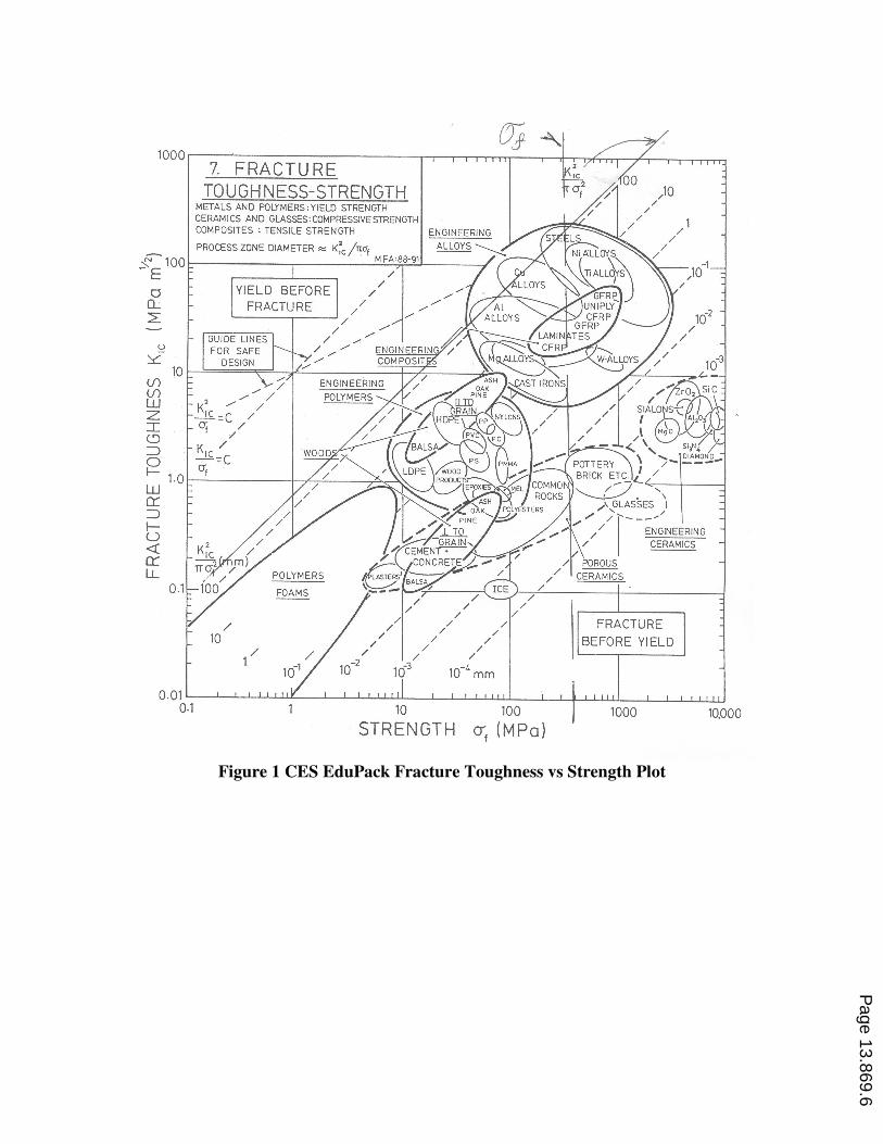
Figure 1 CES EduPack Fracture Toughness vs Strength Plot
Page 13.869.6
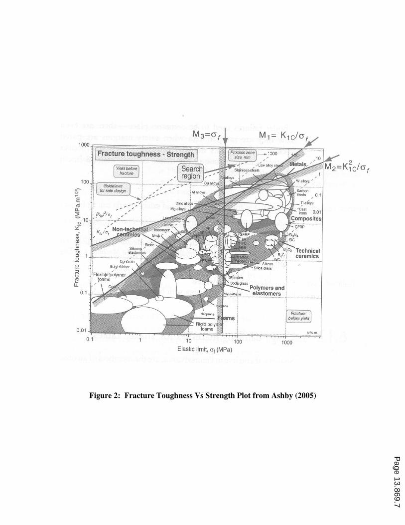
Figure 2: Fracture Toughness Vs Strength Plot from Ashby (2005)
Page 13.869.7
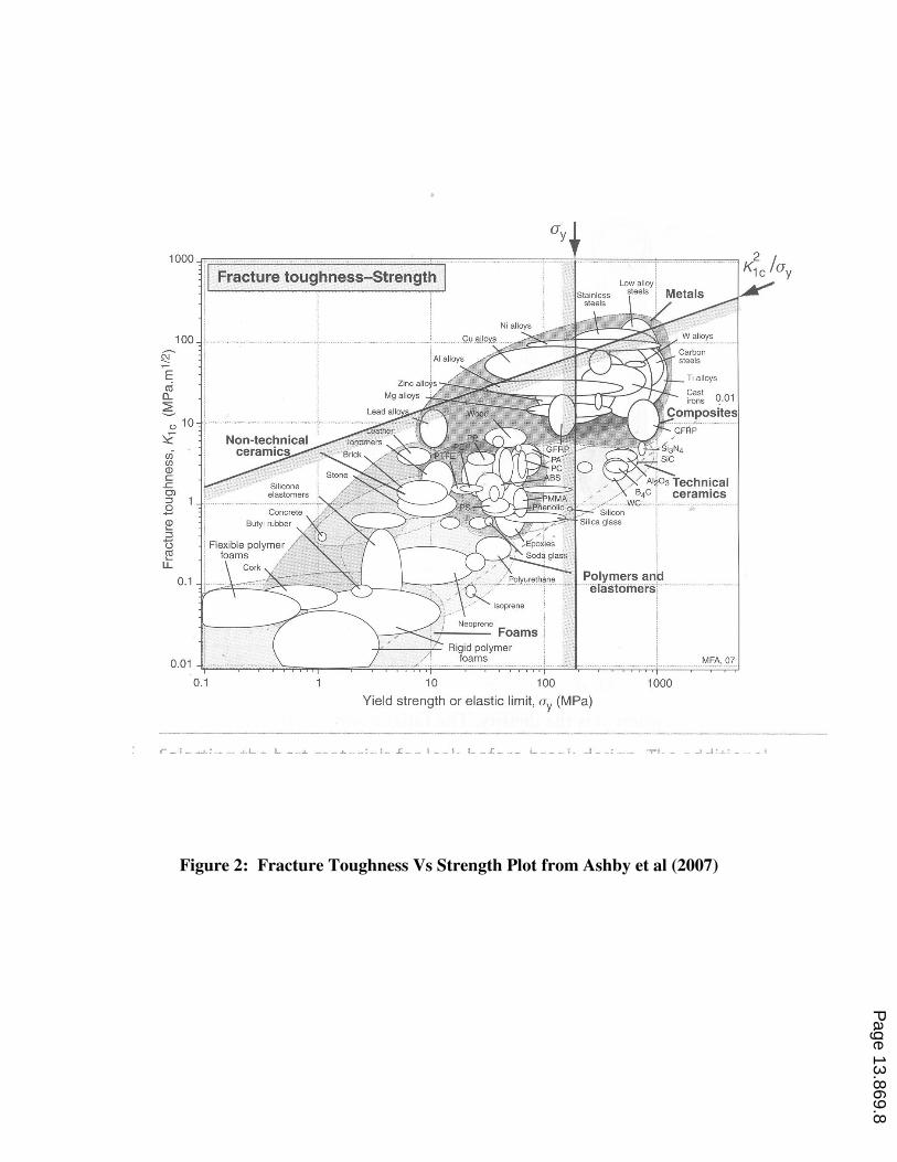
Figure 2: Fracture Toughness Vs Strength Plot from Ashby et al (2007)
Page 13.869.8
•
REFERENCES
Ashby, M. F. (2005), Material Selection in Mechanical Design, 3rd
Edition, Elsevier Butterworth
Heinemann, Burlington, MA
Ashby, M. F., Shercliff, H., and Cebon, D. (2007) Materials: Engineering, Science, Processing and
Design, 1st Edition, Elsevier Butterworth Heinemann, Burlington, MA
Granta Design (2007) CES EduPack , Cambridge, UK.
Irwin, G. R. (1963), “Fracture of Pressure Vessels,” in Materials for Missiles and Spacecraft, McGraw
Hill, New York, pp. 204-229.
Kitagawa , H. and Takahashi, S (1976),” Applicability of fracture mechanics to very small cracks or the
cracks in the early stage,”. Proceedings of Second International Conference on Mechanical Behavior of
Materials, pp. 627-631. Metals Park: American Society of Metals.
Suresh, S. (2004), Fatigue of Materials, 2nd
Edition, Cambridge University Press
Taylor, D. (2007), Theory of Critical Distances, Elsevier.
Wilkowski, G (2000), “Leak-Before-Break: What Does It Really Mean? “ Journal of Pressure Vessel
Technology, Vol. 122. pp. 267-272.
Page 13.869.9