material model for deformation and failure of cast iron for high
TRANSCRIPT
3rd European HyperworksTechnology Conference
2nd - 4th Nov. 2009, Ludwigsburg, Germany
Material Model for Deformation and Failureof Cast Iron for High-Speed Impacts
S. Edelmann / M. Walter / H. Chladek
INPROSIM GmbH © 2009
3rd European HyperworksTechnology Conference2nd - 4th Nov. 2009, Ludwigsburg, Germany
- 2 -
3rd European HyperworksTechnology Conference
2nd - 4th Nov. 2009, Ludwigsburg, Germany
Overview
• Introduction• Use of cast iron / Highly dynamic loading
• Specimen Test• Material data basing on tension and compression tests
• Implementation• Use of the standard and enhanced material implementation
• Impact Test• Verification of the enhanced material implementation
• Summary

- 3 -
3rd European HyperworksTechnology Conference
2nd - 4th Nov. 2009, Ludwigsburg, Germany
Introduction
• Use of cast iron• Cast iron parts have been used for a wide range of applications in
mechanical engineering for a long time
• Previously cast iron parts have often been used for simple parts only
e.g. fittings, wheels, exhaust manifolds,pipes, gates, ovens, boiler, pans, etc.
- 4 -
3rd European HyperworksTechnology Conference
2nd - 4th Nov. 2009, Ludwigsburg, Germany
Introduction
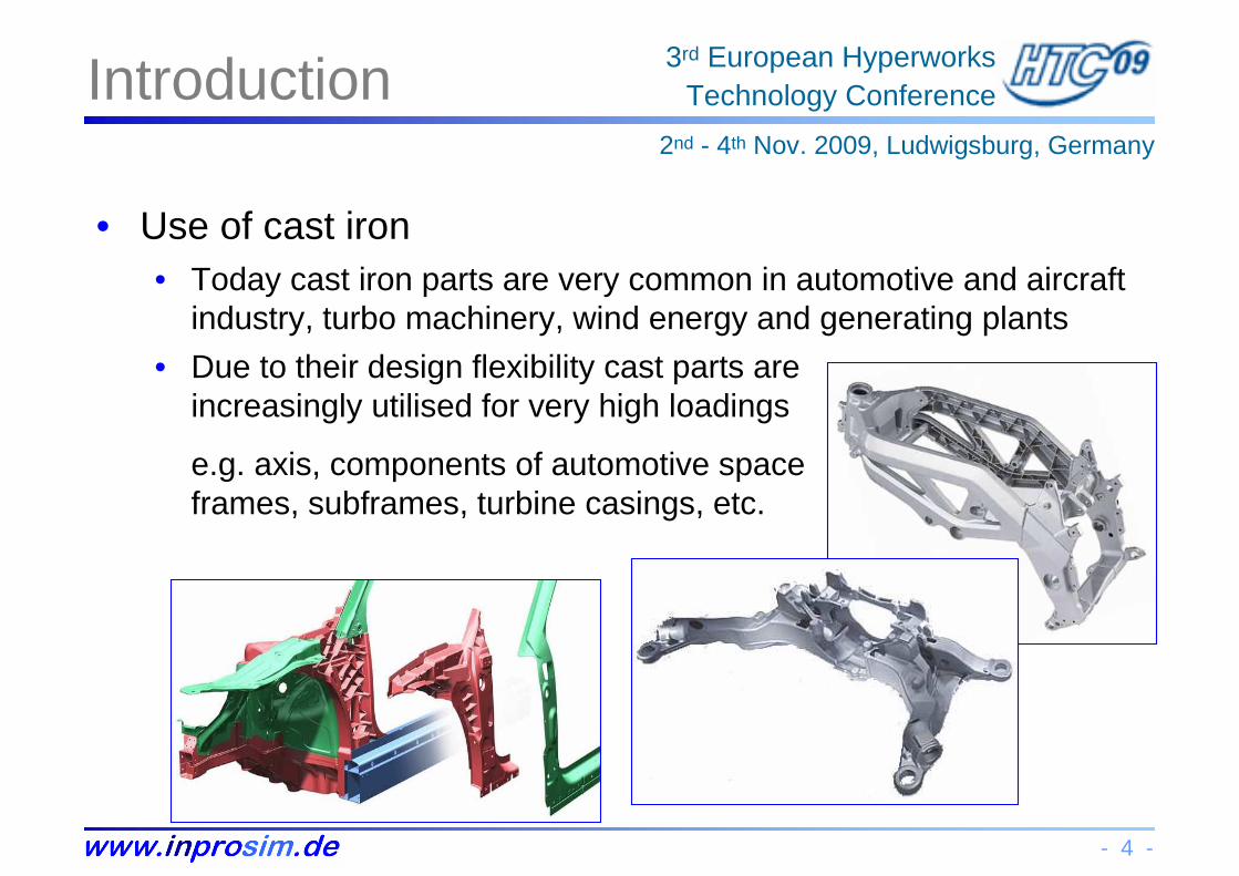
• Use of cast iron• Today cast iron parts are very common in automotive and aircraft
industry, turbo machinery, wind energy and generating plants
• Due to their design flexibility cast parts are increasingly utilised for very high loadings
e.g. axis, components of automotive spaceframes, subframes, turbine casings, etc.
- 5 -
3rd European HyperworksTechnology Conference
2nd - 4th Nov. 2009, Ludwigsburg, Germany
Introduction
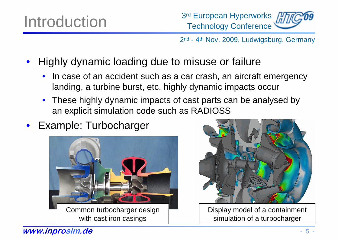
• Highly dynamic loading due to misuse or failure• In case of an accident such as a car crash, an aircraft emergency
landing, a turbine burst, etc. highly dynamic impacts occur
• These highly dynamic impacts of cast parts can be analysed by an explicit simulation code such as RADIOSS
• Example: Turbocharger
Common turbocharger design with cast iron casings
Display model of a containment simulation of a turbocharger

- 6 -
3rd European HyperworksTechnology Conference
2nd - 4th Nov. 2009, Ludwigsburg, Germany
Specimen Tests
• Overview• Specimen tests are required to determine the material properties
• The most common tests are tension tests with quasi-static and dynamic loading, sometimes also considering the temperature
• Tension Test• Tension tests are well known in the industry, nonetheless often
missing in practice due to time and costs
• Anyway, the description of an isotropic elastoplastic material behaviour requires a stress-strain-curve input
• Compression Test• In addition compression tests are required for the analysis of a
possible interrelation of behaviour under tension and compression
- 7 -
3rd European HyperworksTechnology Conference
2nd - 4th Nov. 2009, Ludwigsburg, Germany
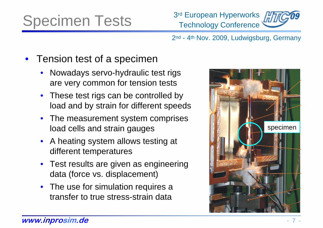
Specimen Tests
• Tension test of a specimen• Nowadays servo-hydraulic test rigs
are very common for tension tests
• These test rigs can be controlled byload and by strain for different speeds
• The measurement system comprisesload cells and strain gauges
• A heating system allows testing at different temperatures
• Test results are given as engineering data (force vs. displacement)
• The use for simulation requires atransfer to true stress-strain data
specimen
- 8 -
3rd European HyperworksTechnology Conference
2nd - 4th Nov. 2009, Ludwigsburg, Germany
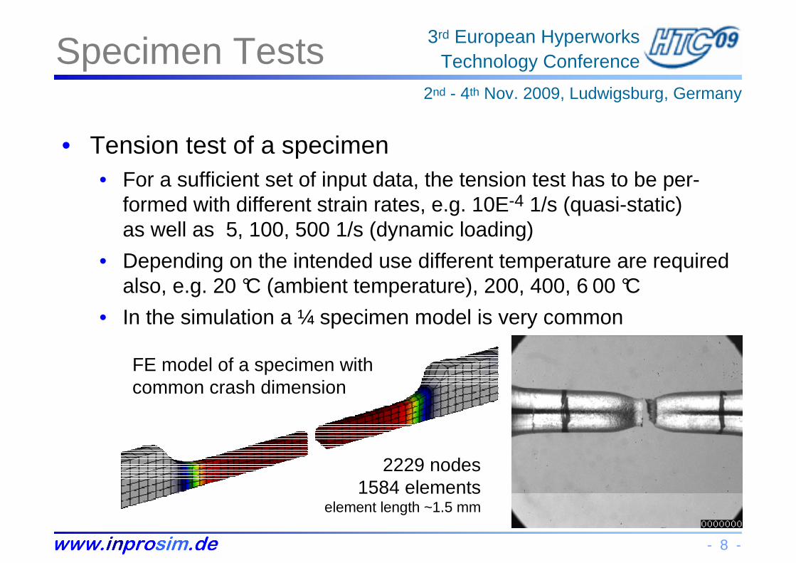
Specimen Tests
• Tension test of a specimen• For a sufficient set of input data, the tension test has to be per-
formed with different strain rates, e.g. 10E-4 1/s (quasi-static)as well as 5, 100, 500 1/s (dynamic loading)
• Depending on the intended use different temperature are requiredalso, e.g. 20 °C (ambient temperature), 200, 400, 6 00 °C
• In the simulation a ¼ specimen model is very common
2229 nodes1584 elements
element length ~1.5 mm
FE model of a specimen with common crash dimension

- 9 -
3rd European HyperworksTechnology Conference
2nd - 4th Nov. 2009, Ludwigsburg, Germany
Specimen Tests
• Tension test of a specimen• Typical effects of higher strain rate and higher temperature
true straintrue strain
true
str
ess
true
str
ess
decreasing by higher temperature
increasing by higherstrain rate
- 10 -
3rd European HyperworksTechnology Conference
2nd - 4th Nov. 2009, Ludwigsburg, Germany
Specimen Tests
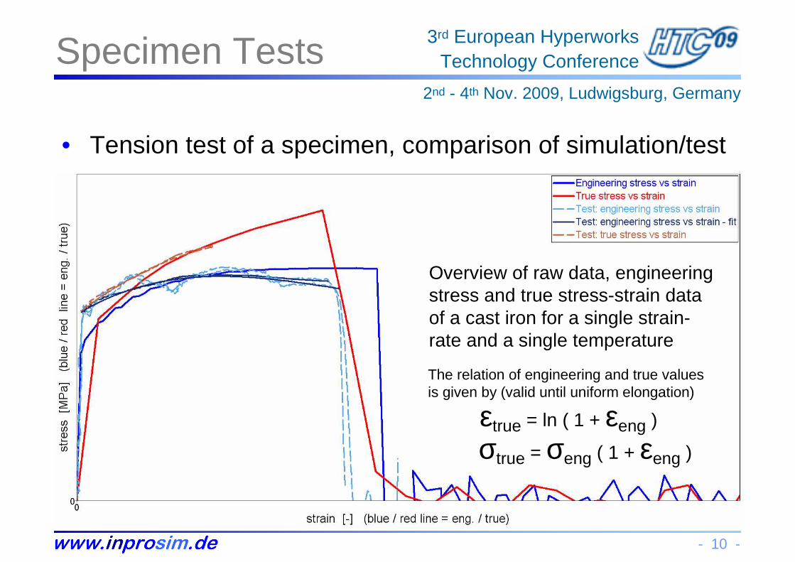
• Tension test of a specimen, comparison of simulation/test
Overview of raw data, engineering stress and true stress-strain data of a cast iron for a single strain-rate and a single temperature
εtrue = ln ( 1 + εeng )
σtrue = σeng ( 1 + εeng )
The relation of engineering and true values is given by (valid until uniform elongation)

- 11 -
3rd European HyperworksTechnology Conference
2nd - 4th Nov. 2009, Ludwigsburg, Germany
Specimen Tests
• Compression Test• An additional compression test allows the analysis of a possible
interrelation of material behaviour under tension and compression
• But as testing under highly dynamic loading is very difficult, normally this test is done with quasi-static loading
• There is a significant influence of the friction between the specimen and the plates of the test rig
FE model of a specimen with common crash dimension
1929 nodes1604 elements
element length ~0.8 mm
Specimenbefore and after test

- 12 -
3rd European HyperworksTechnology Conference
2nd - 4th Nov. 2009, Ludwigsburg, Germany
Specimen Tests
• Compression Test
Overview of raw test data, engineering stress and true stress-strain data of a castiron for a single strain-rateand a single temperature
In compression tests it’s not easy to identify the limit of plastic strain, because there is no breaking into two parts.So a common criterion is the appearance of the first shear lines
- 13 -
3rd European HyperworksTechnology Conference
2nd - 4th Nov. 2009, Ludwigsburg, Germany
Implementation
• Overview• RADIOSS offers a wide range of different material laws that are
very common in explicit respectively crash simulation
• Examples are /MAT/LAW2 (Johnson-Cook) with polynomial input or /MAT/LAW36 with tabulated input, which is preferred today
• Standard material implementation• Using /MAT/LAW36 as a standard crash material for a common
description of an isotropic elastoplastic material law
• Enhanced material implementation• Different stress-strain-curves for tension and compression
• Different failure modes for tension and compression (triaxiality)

- 14 -
3rd European HyperworksTechnology Conference
2nd - 4th Nov. 2009, Ludwigsburg, Germany
Implementation
• Standard material implementation• Using /MAT/LAW36 as a standard material description for crash
simulation with an isotropic elastoplastic material law
• Common input data• Physical data e.g. bulk modulus, density, Poisson’s ration, etc.
• Maximum plastic strain (element eroding if this limit is reached)
• Isotropic / kinematic hardening formulation
• Yield stress functions for different strain rates• The first curve represents the lower limit of strain-rates (quasi-static)
• Extrapolation for higher strain rates using the two last curves
• Linear interpolation between two strain-rates
• Remark: stress-strain-curves are based on tension tests
- 15 -
3rd European HyperworksTechnology Conference
2nd - 4th Nov. 2009, Ludwigsburg, Germany
Implementation
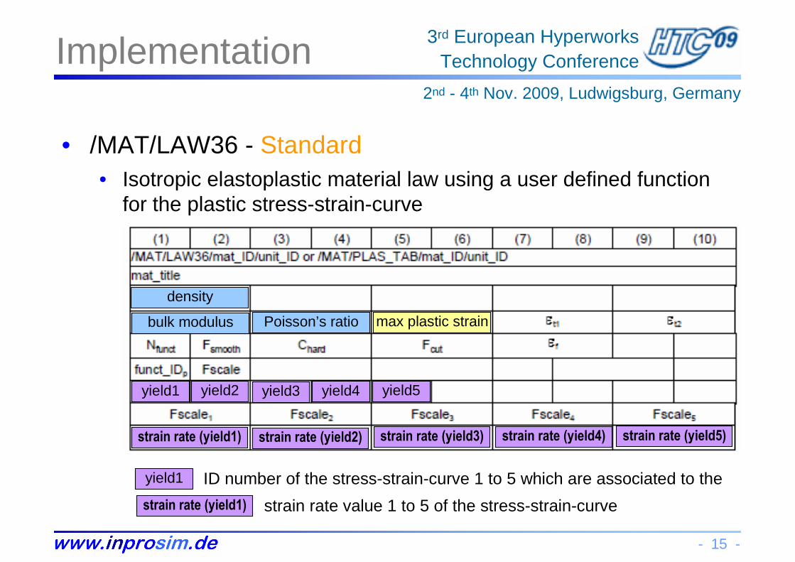
• /MAT/LAW36 - Standard• Isotropic elastoplastic material law using a user defined function
for the plastic stress-strain-curve
density
bulk modulus Poisson’s ratio max plastic strain
yield1 yield2 yield3 yield4 yield5
strain rate (yield1) strain rate (yield2) strain rate (yield3) strain rate (yield4) strain rate (yield5)
yield1 ID number of the stress-strain-curve 1 to 5 which are associated to the
strain rate (yield1) strain rate value 1 to 5 of the stress-strain-curve
- 16 -
3rd European HyperworksTechnology Conference
2nd - 4th Nov. 2009, Ludwigsburg, Germany
Implementation
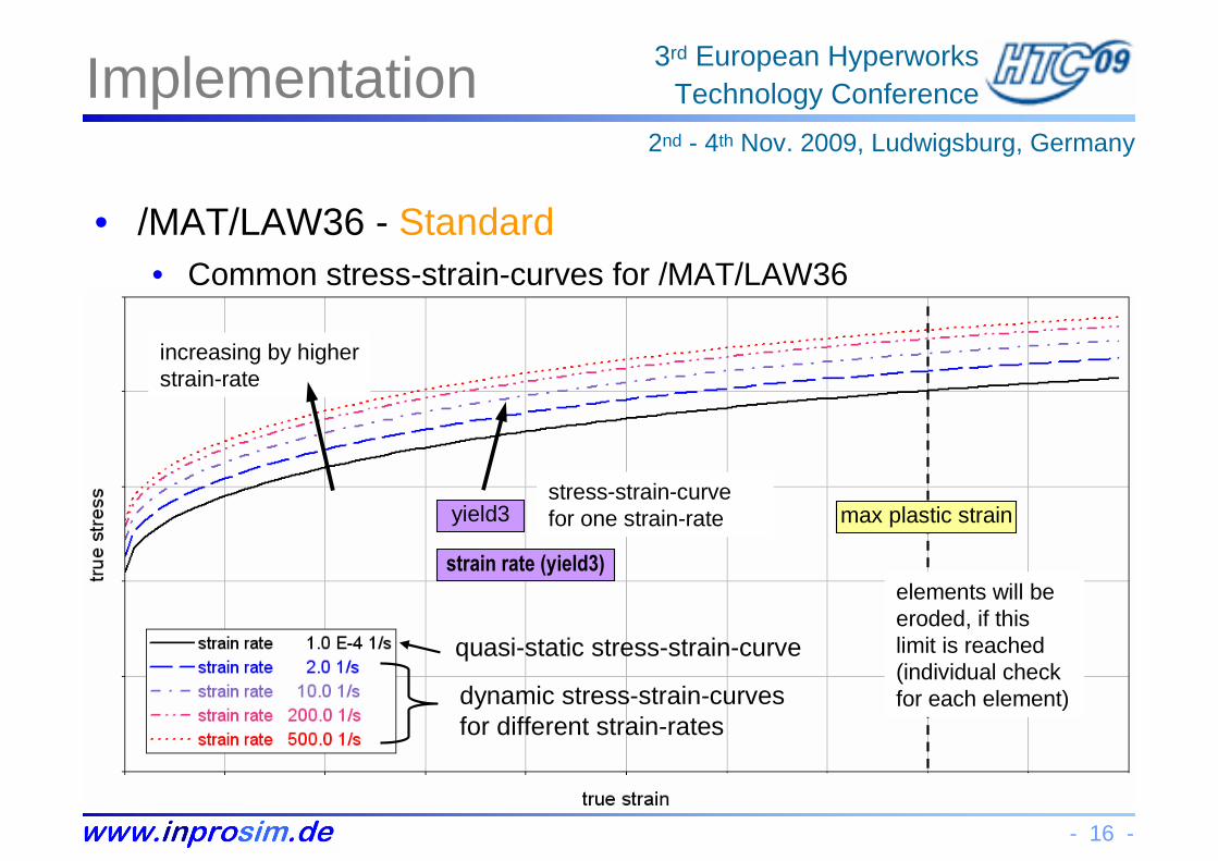
• /MAT/LAW36 - Standard• Common stress-strain-curves for /MAT/LAW36
quasi-static stress-strain-curve
dynamic stress-strain-curves for different strain-rates
max plastic strain
elements will be eroded, if thislimit is reached(individual check for each element)
yield3
strain rate (yield3)
increasing by higherstrain-rate
stress-strain-curve for one strain-rate
- 17 -
3rd European HyperworksTechnology Conference
2nd - 4th Nov. 2009, Ludwigsburg, Germany
Implementation
• Enhanced material implementation• Using /MAT/LAW36 as a standard material description for crash
simulation with an isotropic elastoplastic material law
• Additional feature - Enhancement 1• Different stress-strain-curves for tension and compression
• Physical background• Most cast iron materials have significant differences in the stress-
strain-curves for tension and for compression
• This has to be taken into account for 3D-structures especially
• This can be implemented directly into the standard material card/MAT/LAW36, no extra card is needed

- 18 -
3rd European HyperworksTechnology Conference
2nd - 4th Nov. 2009, Ludwigsburg, Germany
Implementation
• /MAT/LAW36 - Enhancement 1• Enhanced material implementation for the relationship of
compression and tension by using the standard card
density
bulk modulus poisson’s ratio max plastic strain
yield1 yield2 yield3 yield4 yield5
strain rate (yield1) strain rate (yield2) strain rate (yield3) strain rate (yield4) strain rate (yield5)
ID number of the compression / tension relationship
scaling factor for the relationship
pressure
pressure
scale
scale
- 19 -
3rd European HyperworksTechnology Conference
2nd - 4th Nov. 2009, Ludwigsburg, Germany
Implementation
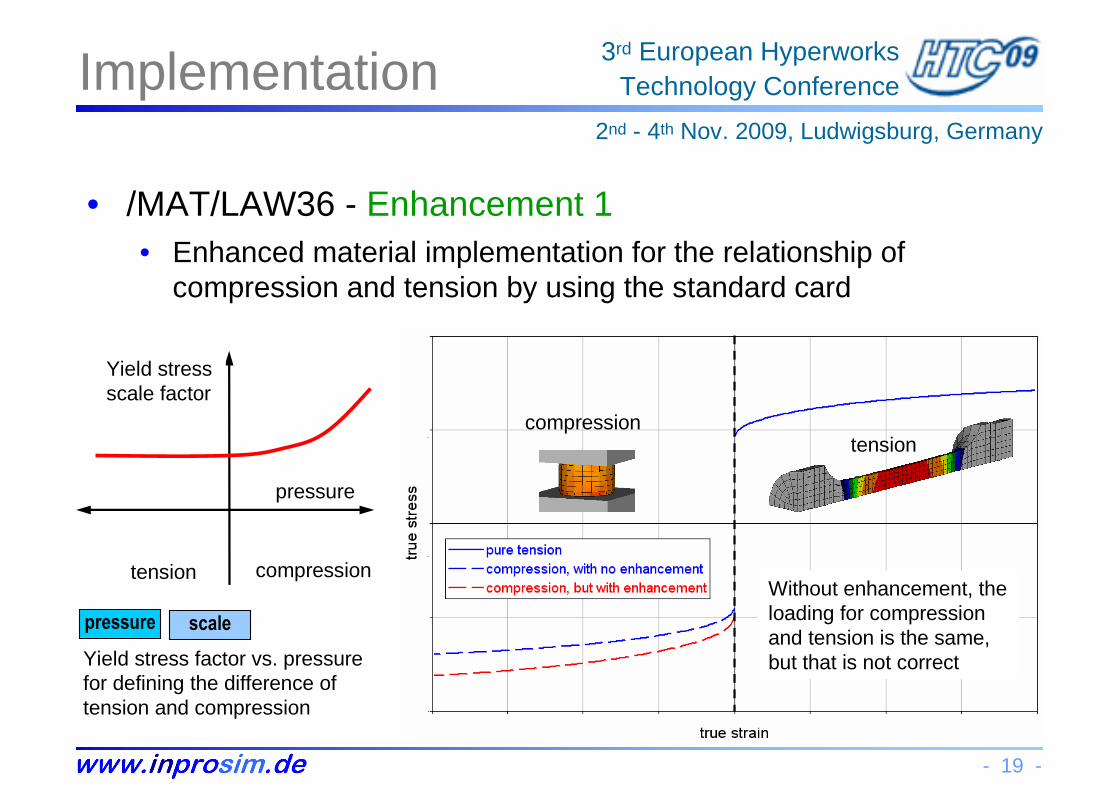
• /MAT/LAW36 - Enhancement 1• Enhanced material implementation for the relationship of
compression and tension by using the standard card
tensioncompression
Without enhancement, the loading for compression and tension is the same, but that is not correct
tension compression
Yield stress scale factor
pressure
pressure scale
Yield stress factor vs. pressurefor defining the difference of tension and compression
- 20 -
3rd European HyperworksTechnology Conference
2nd - 4th Nov. 2009, Ludwigsburg, Germany
Implementation
• Enhanced material implementation• Using /MAT/LAW36 as a standard material description for crash
simulation with an isotropic elastoplastic material law
• Additional feature - Enhancement 2• Different failure modes for tension and for compression (triaxiality)
• Physical background• Most cast iron materials also have significant differences in the
failure mode due to tension and due to compression
• This has to be taken into account for all simulation with fracture
• This effect can be described by an additional failure card whichcan be associated to the used material card

- 21 -
3rd European HyperworksTechnology Conference
2nd - 4th Nov. 2009, Ludwigsburg, Germany
Implementation
• Enhancement 2 /FAIL/JOHNSON - physical background• Enhanced material implementation for the failure relationship of
compression and tension using the additional /FAIL card
• The failure relationship is definedby a function of mid-stress levelto von-Mises stress
• This relation is named triaxiality
-0.333 = compression
0.0 = shear
+0.333 = tension
σ mid
σvm
( )*, σε FPfT =

- 22 -
3rd European HyperworksTechnology Conference
2nd - 4th Nov. 2009, Ludwigsburg, Germany
Implementation
• Enhancement 2 / FAIL/JOHNSON• Enhanced material implementation for the failure relationship of
compression and tension using the additional /FAIL card
• The relationship (failure curve) is defined by at least three failure parameters D1 to D3, D4 and D5 can be added optionally
-> therefore normalized mean stress σ* = σM / σVM
Damage Factor 1 Damage Factor 2 Damage Factor 3 Damage Factor 4 Damage Factor 5
- 23 -
3rd European HyperworksTechnology Conference
2nd - 4th Nov. 2009, Ludwigsburg, Germany
Impact Test
• Overview• The impact test is a simple but repeatable test for analysing a
multiaxial stress combination under highly dynamic loading
• Thus in this presentation the impact test is used for demonstrating the qualities of the material implementations described above
• Verification / Comparison of test and simulation• The calculations were carried out using different initial speeds of
the bullet when hitting the plate
• This allows to determine the limit of specific energy needed for a full penetration and to compare it for test and simulation
• The simulation compares the standard material law versus the optimised i.e. the enhanced material implementation with the additional failure specification

- 24 -
3rd European HyperworksTechnology Conference
2nd - 4th Nov. 2009, Ludwigsburg, Germany
Impact Test
• Impact Test• For this impact test the same
cast iron material is used forthe plate and for the bullet
• The plate is clamped by a rigidsteel frame
• The bullet has different initial speeds
• Simulation• Comparison of standard material and
optimised material implementation• Standard = /MAT/LAW36
• Optimised = /MAT/LAW36 + /FAIL/JC
bullet
frame
plate
impact
Enhancement 2Enhancement 1 +

- 25 -
3rd European HyperworksTechnology Conference
2nd - 4th Nov. 2009, Ludwigsburg, Germany
Impact Test
• Comparison of both material implementations
Standard Material Implementation Optimised Material Implementation
plastic strain [-]
min
max
plastic strain [-]
min
max

- 26 -
3rd European HyperworksTechnology Conference
2nd - 4th Nov. 2009, Ludwigsburg, Germany
Impact Test
• Comparison of both material implementations
Standard Material Implementation Optimised Material Implementation
plastic strain [-]
min
max
plastic strain [-]
min
max

- 27 -
3rd European HyperworksTechnology Conference
2nd - 4th Nov. 2009, Ludwigsburg, Germany
Impact Test
• Comparison of impact test and simulation
The optimised material law with the enhanced material and the additional failure specification leads to an excellent correlation of deformation and failure behaviour and meets the specific energy which is needed for a full penetration

- 28 -
3rd European HyperworksTechnology Conference
2nd - 4th Nov. 2009, Ludwigsburg, Germany
Summary
• Cast Iron Parts• Due to design flexibility and low costs, cast iron parts are used
increasingly for very high loadings in a wide range of applications
• But for highly dynamic loads with a significant failure behaviour, e.g. in a car crash, an impeller burst, etc. a standard material law defined only by a tension test is no longer sufficient
• In particular for cast iron parts, the different behaviour undertension and compression in the stress-strain curves as well as in the failure behaviour have to be taken into account
• CAE Simulation / Process• RADIOSS Explicit can handle this by using common crash
material laws, which can enhanced very comfortably with specificparameters and with an add-on of given failure criteria cards
- 29 -
3rd European HyperworksTechnology Conference
2nd - 4th Nov. 2009, Ludwigsburg, Germany
Appendix
• Acknowledgement / References• German Research Association for Combustion Engines (FVV)
• for allowing to attend sophisticated research programs,in particular, the research program FVV 0936 (Containment safety)
• Federal Institute for Materials Research and Testing (BAM)• for their activity on a specimen test programme for cast iron
• Fraunhofer Institute for Mechanics of Materials (IWM) • for their research for a better cast iron material description
• References / Internet• www.de.wikipedia.org www.konstruktionspraxis.vogel.de
• www.honsel.com/honsel.php www.temming-online.de
• www.claasguss.de/html/home.html www.audia2museum.de/54.html
• www.svrider.de/Homepage/SV1000FAQ/SV1000FAQ_rahmen.jpg