material forces for 3d crack propagation in xfem forces for 3d crack propagation in xfem m. baydoun...
TRANSCRIPT
Material forces for 3D crack propagation in XFEMpropagation in XFEM
M. Baydoun & T. P. FriesCFRAC‐20118th June
AACHEN INSTITUTE FOR ADVANCED STUDYIN COMPUTATIONAL ENGINEERING SCIENCE
OutlineOutline
I Traditional crack propagation in XFEMI. Traditional crack propagation in XFEM.II. Hybrid explicit implicit crack description.III. Material forces as propagation criteria in FEM.p p gIV. Material forces as propagation criteria in XFEM.V. Numerical results.VI. Conclusions and outlook.
28/6/2011 M.Baydoun & T.P.Fries: Material forces in 3D XFEM
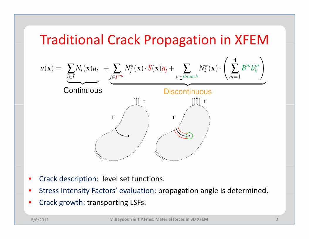
Traditional Crack Propagation in XFEMTraditional Crack Propagation in XFEM
• Crack description: level set functions.• Stress Intensity Factors’ evaluation: propagation angle is determined.• Crack growth: transporting LSFs.
38/6/2011 M.Baydoun & T.P.Fries: Material forces in 3D XFEM
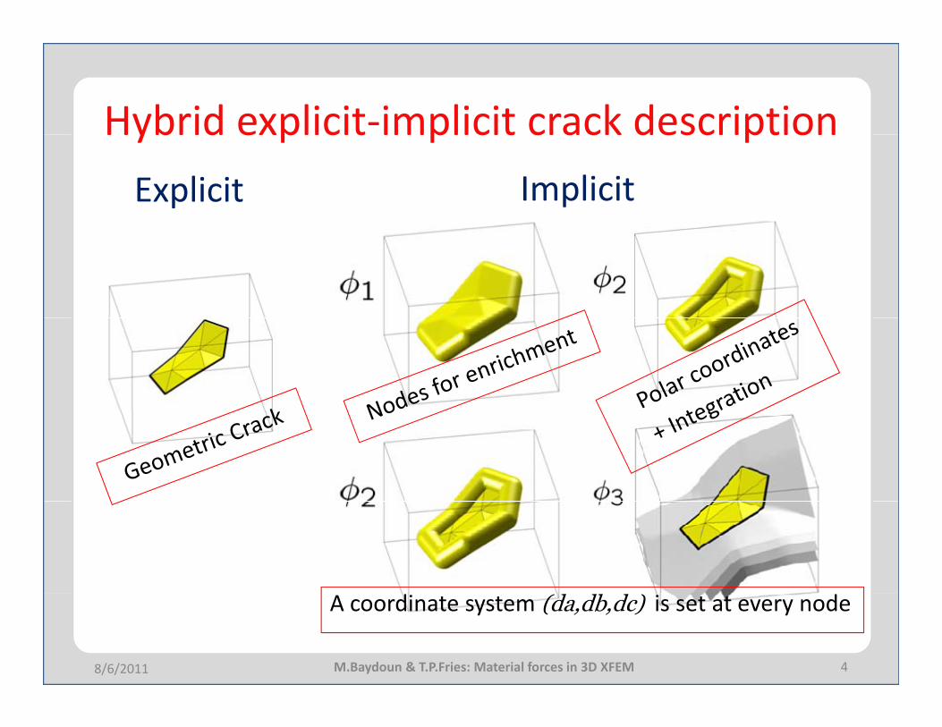
Hybrid explicit‐implicit crack descriptionHybrid explicit implicit crack descriptionExplicit Implicit
48/6/2011 M.Baydoun & T.P.Fries: Material forces in 3D XFEM
A coordinate system (da,db,dc) is set at every node
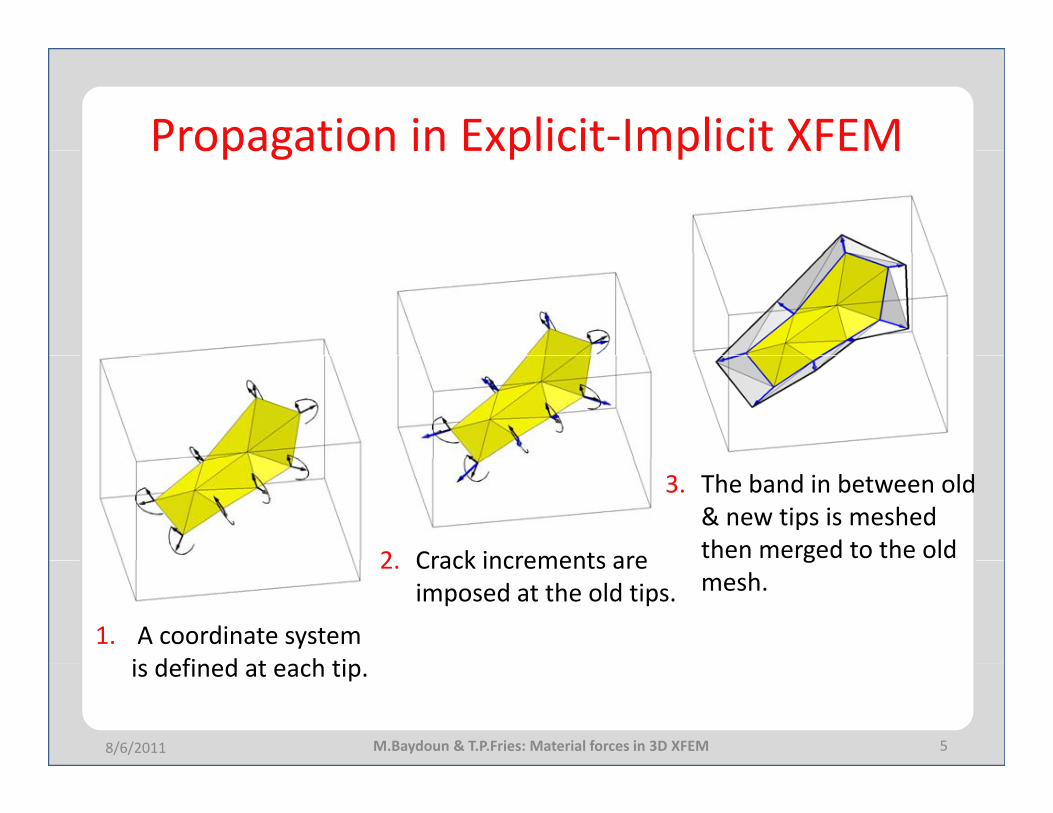
Propagation in Explicit‐Implicit XFEMPropagation in Explicit Implicit XFEM
2 Crack increments are
3. The band in between old & new tips is meshed then merged to the old
1. A coordinate system i d fi d t h ti
2. Crack increments are imposed at the old tips.
gmesh.
5
is defined at each tip.
8/6/2011 M.Baydoun & T.P.Fries: Material forces in 3D XFEM

Material ForcesMaterial Forces• Global dissipation is positive
0:))((: ≥∇∇−⋅−∇−= ∫∫ dVauIWdVuDV
T
V
&& σσ
• A duality between the stress driving the change in the displacement and a stress like quantity driving the crack evolution .a&
• This stress like tensor is the Eshelby tensor or the material stress tensor as it drives the increment of the crack.
σ)( uIW T∇−⋅=Σ
68/6/2011 M.Baydoun & T.P.Fries
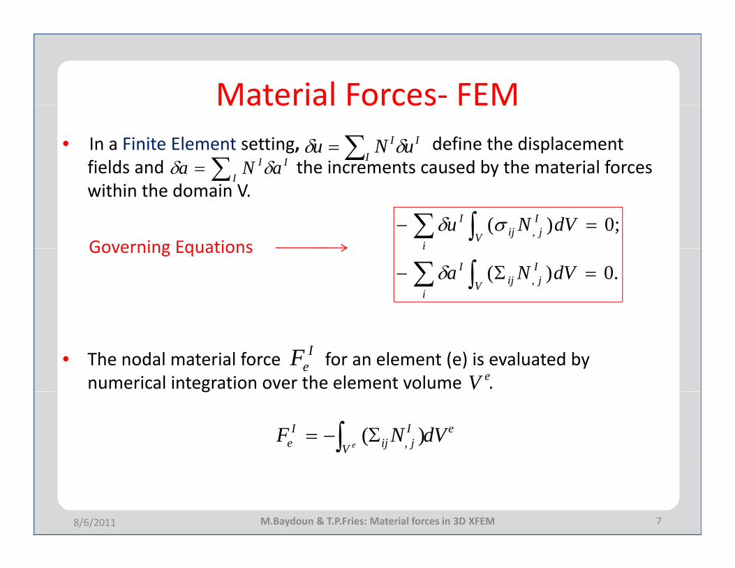
Material Forces‐ FEMMaterial Forces FEM• In a Finite Element setting, define the displacement
fields and the increments caused by the material forces I
II uNu δδ ∑=
II
I aNa δδ ∑= ywithin the domain V.
Governing Equations
I∑
;0)( , =− ∫∑ dVNu IjV ij
i
I σδGoverning Equations
.0)( , =Σ− ∫∑ dVNa IjV ij
i
I
i
δ
• The nodal material force for an element (e) is evaluated by numerical integration over the element volume .
IeF
eVg
e
V
Ijij
Ie dVNF
e∫ Σ−= )( ,
78/6/2011 M.Baydoun & T.P.Fries: Material forces in 3D XFEM
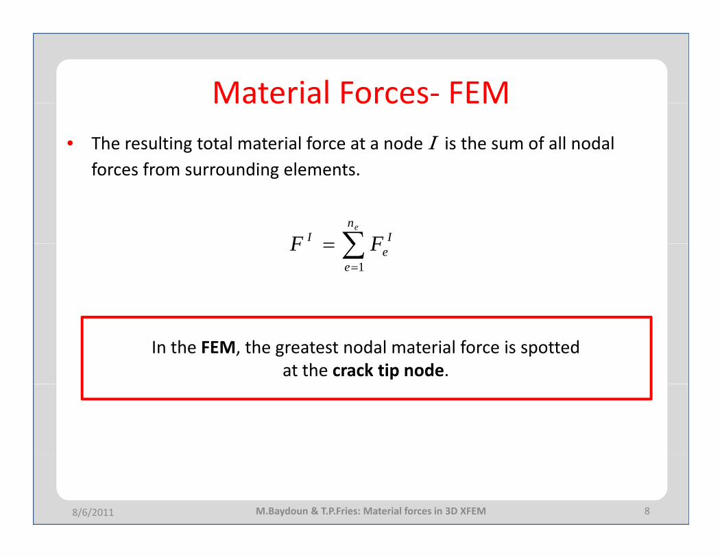
Material Forces‐ FEMMaterial Forces FEM• The resulting total material force at a node I is the sum of all nodal
forces from surrounding elements.forces from surrounding elements.
∑=en
II FF ∑=
=e
eFF1
In the FEM, the greatest nodal material force is spotted at the crack tip node.
88/6/2011 M.Baydoun & T.P.Fries: Material forces in 3D XFEM
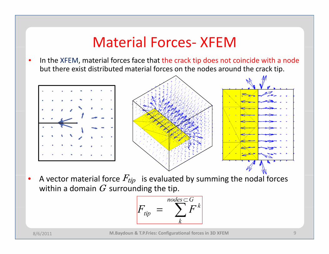
Material Forces‐ XFEMMaterial Forces XFEM• In the XFEM, material forces face that the crack tip does not coincide with a node
but there exist distributed material forces on the nodes around the crack tip.
F• A vector material force is evaluated by summing the nodal forces within a domain G surrounding the tip.
tipF
98/6/2011 M.Baydoun & T.P.Fries: Configurational forces in 3D XFEM
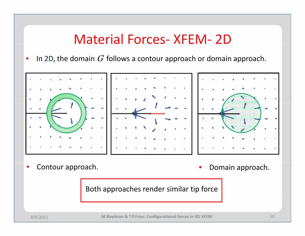
Material Forces‐ XFEM‐ 2DMaterial Forces XFEM 2D• In 2D, the domain G follows a contour approach or domain approach.
• Contour approach. • Domain approach.
Both approaches render similar tip force
10
pp p
8/6/2011 M.Baydoun & T.P.Fries: Configurational forces in 3D XFEM
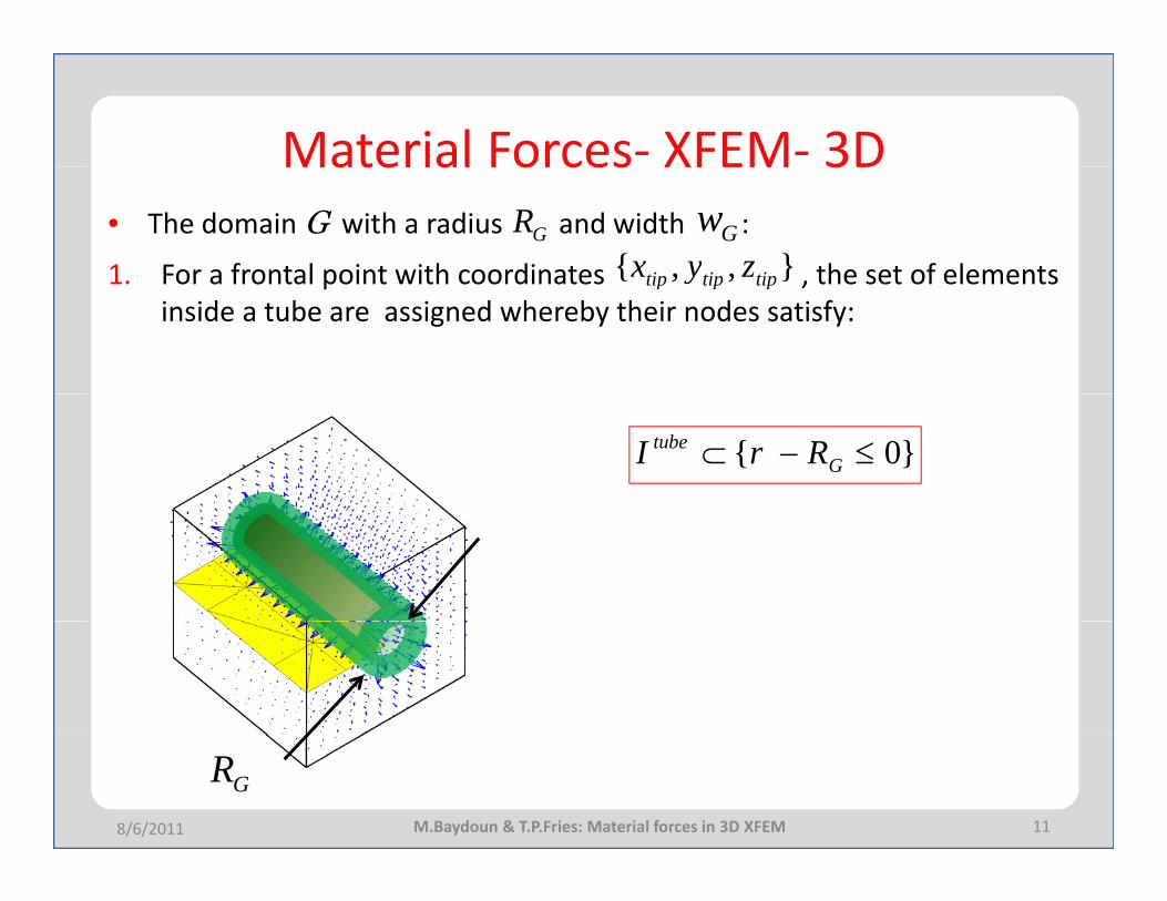
Material Forces‐ XFEM‐ 3DMaterial Forces XFEM 3D• The domain G with a radius and width :
1 For a frontal point with coordinates the set of elementsGR
},,{ tiptiptip zyxGw
1. For a frontal point with coordinates , the set of elements inside a tube are assigned whereby their nodes satisfy:
},,{ tiptiptip y
}0{ ≤−⊂ Gtube RrI
118/6/2011
GRM.Baydoun & T.P.Fries: Material forces in 3D XFEM
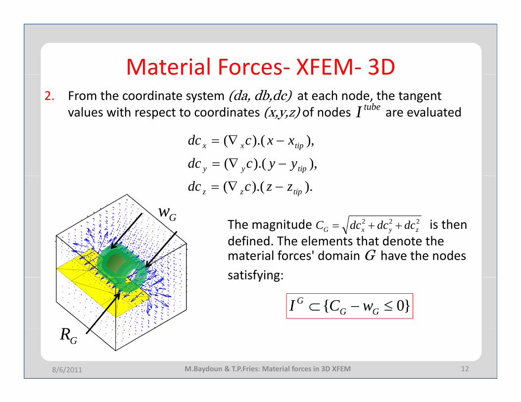
Material Forces‐ XFEM‐ 3DMaterial Forces XFEM 3D2. From the coordinate system (da, db,dc) at each node, the tangent
values with respect to coordinates (x,y,z) of nodes are evaluatedtubeI
),).((
),).((
tipyy
tipxx
yycdc
xxcdc
−∇=
−∇=
222 dcdcdcC ++=
).).(( tipzz zzcdc −∇=
The magnitude is thenGwzyxG dcdcdcC ++=The magnitude is then
defined. The elements that denote the material forces' domain G have the nodes satisfying:
}0{ ≤−⊂ GGG wCI
satisfying:
128/6/2011
GR
M.Baydoun & T.P.Fries: Material forces in 3D XFEM
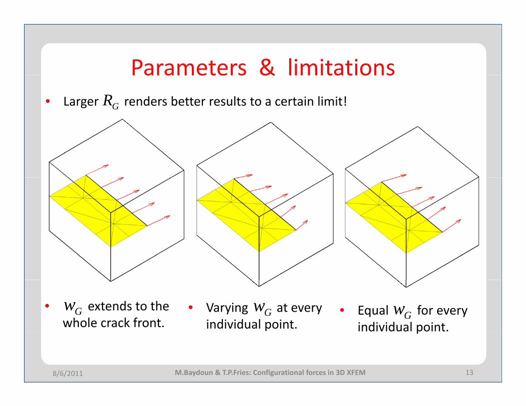
Parameters & limitationsParameters & limitations• Larger renders better results to a certain limit!GR
• extends to the whole crack front.
• Varying at every individual point.
• Equal for every individual point.
Gw GwGw
13
individual point.
8/6/2011 M.Baydoun & T.P.Fries: Configurational forces in 3D XFEM

Parameters & limitationsParameters & limitations• Mesh dependency
9261
1331
9261
3375
148/6/2011 M.Baydoun & T.P.Fries: Configurational forces in 3D XFEM
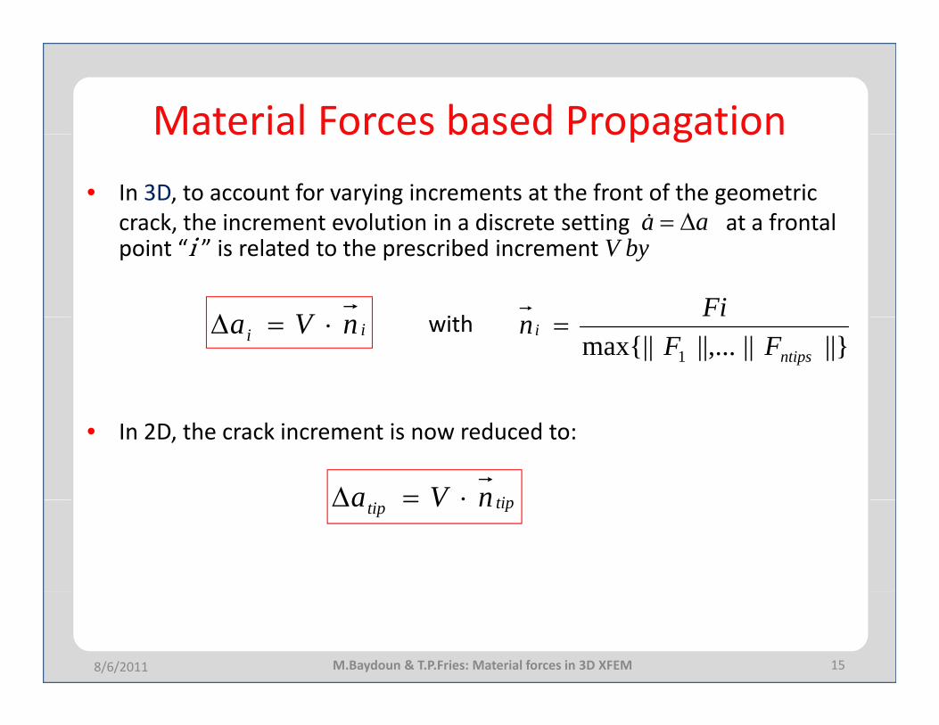
Material Forces based PropagationMaterial Forces based Propagation• In 3D, to account for varying increments at the front of the geometric
crack the increment evolution in a discrete setting at a frontalaa Δ=&crack, the increment evolution in a discrete setting at a frontal point “i ” is related to the prescribed increment V by
i hVΔ
aa Δ=
Fiwith ii nVa ⋅=Δ
||}||||,...max{|| 1 ntips
iFF
n =
• In 2D, the crack increment is now reduced to:
tinVa ⋅=Δ tiptip nVa ⋅=Δ
158/6/2011 M.Baydoun & T.P.Fries: Material forces in 3D XFEM
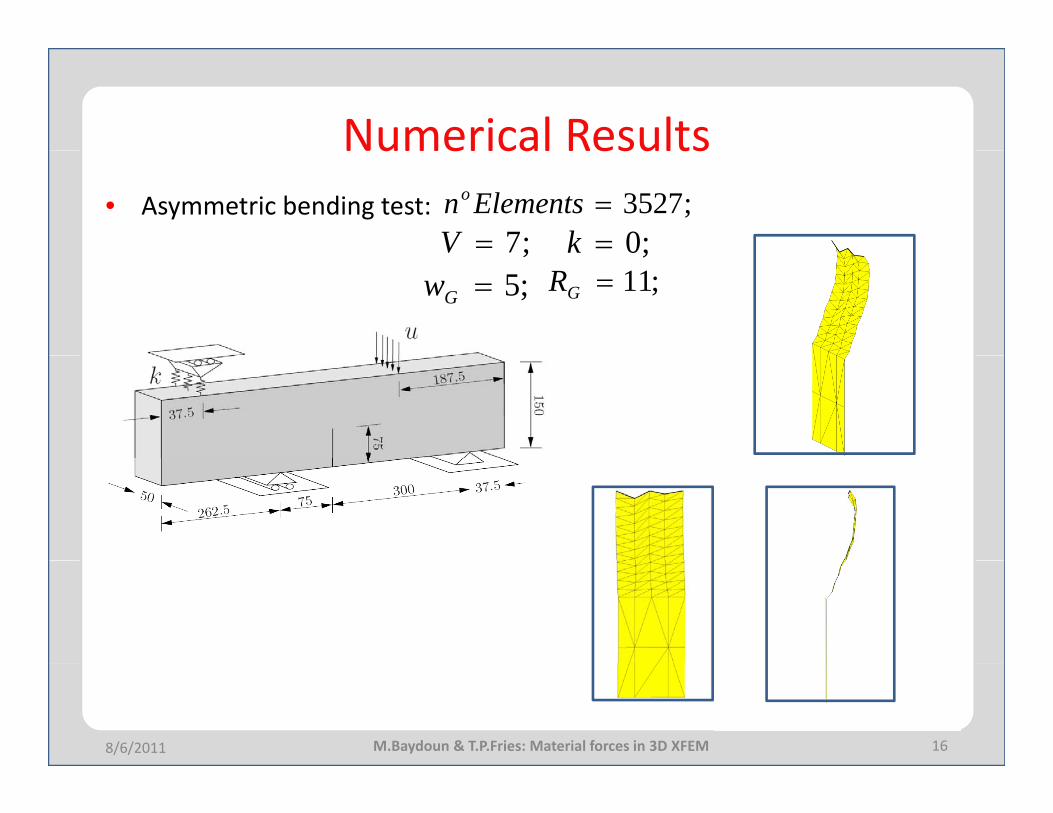
Numerical ResultsNumerical Results• Asymmetric bending test:
;0=k;7=V;3527=Elementsno
;11=GR;5=Gw;0k;
168/6/2011 M.Baydoun & T.P.Fries: Material forces in 3D XFEM
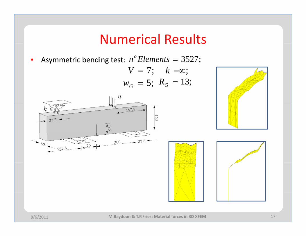
Numerical ResultsNumerical Results• Asymmetric bending test:
;=∝k;7=V;3527=Elementsno
;13=GR;5=Gw;k;
178/6/2011 M.Baydoun & T.P.Fries: Material forces in 3D XFEM
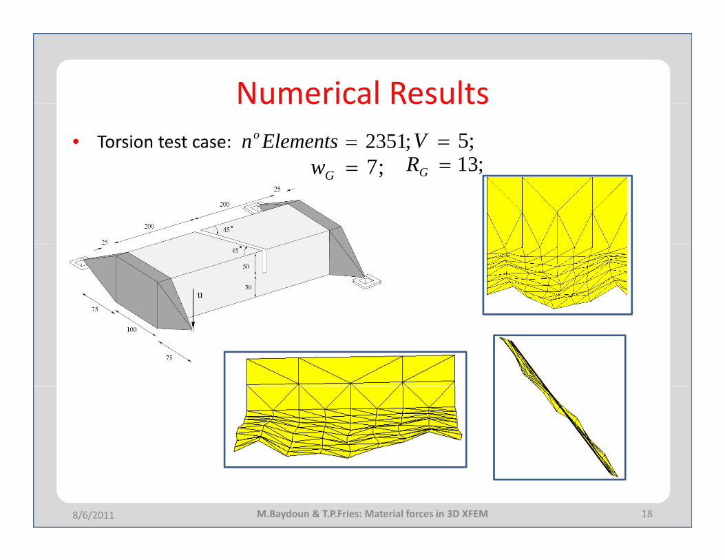
Numerical ResultsNumerical Results• Torsion test case: ;2351=Elementsno
;13=GR;7=Gw;5=V;G;7Gw
188/6/2011 M.Baydoun & T.P.Fries: Material forces in 3D XFEM
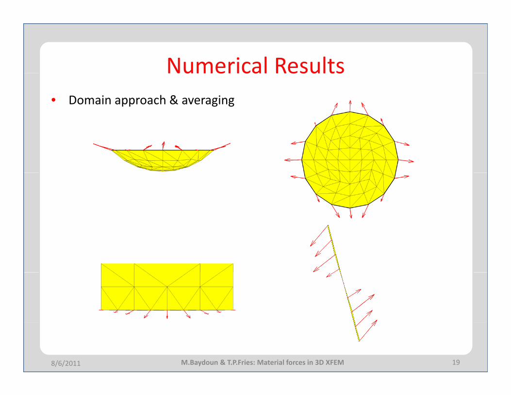
Numerical ResultsNumerical Results• Domain approach & averaging
198/6/2011 M.Baydoun & T.P.Fries: Material forces in 3D XFEM

ConclusionsConclusions
• Material forces as geometric propagation criteria in 3D XFEM.• Effects of the width and radius of the domain.• Having an equal domain is very hard: Averaging is required. • Limited dependency on the mesh size
GRGw
Limited dependency on the mesh size.• Similar crack paths to existing propagation results.
Outlook • Further Studies on .• Comparative study between material forces and MCSC in XFEM.
Gw
208/6/2011 M.Baydoun & T.P.Fries: Material forces in 3D XFEM