mastertrace manual pdfa - aef sales manual.pdf2.4 test heater & alarms ... 1-3 and 1-4 wired and...
TRANSCRIPT

MASTERTRACE TM
OPERATOR�S MANUAL
HEAT TRACING CONTROL
ISO 9001 Registered
MASTERTRACE Contents
1 Overview ....................................................................................................................... 1.11.1 Use of This Manual ............................................................................................................................ 1.11.2 Related Documents ............................................................................................................................ 1.11.3 Conventions ....................................................................................................................................... 1.11.4 Scope ................................................................................................................................................. 1.1
2 Getting Started.............................................................................................................. 2.12.1 Introduction ........................................................................................................................................ 2.12.2 Enable Heaters .................................................................................................................................. 2.12.3 Enter Setpoints ................................................................................................................................... 2.22.4 Test Heater & Alarms ......................................................................................................................... 2.42.5 Monitor System Status ....................................................................................................................... 2.5
3 Product Description ..................................................................................................... 3.13.1 Introduction ........................................................................................................................................ 3.13.2 Features and Benefits ........................................................................................................................ 3.23.3 Control Module Specifications ............................................................................................................ 3.33.4 Model Codes for Control Panels ....................................................................................................... 3.14
4 Installation .................................................................................................................... 4.14.1 Control Panel Mounting ...................................................................................................................... 4.14.2 RTD Sensor Wiring ............................................................................................................................ 4.14.3 Ground Fault Protection ..................................................................................................................... 4.14.4 Ground Fault Testing .......................................................................................................................... 4.14.5 Heater Wiring ..................................................................................................................................... 4.14.6 Ground Connection ............................................................................................................................ 4.14.7 Safety Ground .................................................................................................................................... 4.14.8 Control Power Wiring ......................................................................................................................... 4.14.9 Commissioning .................................................................................................................................. 4.2
5 Operation ...................................................................................................................... 5.15.1 Control Modules ................................................................................................................................. 5.15.2 Interface Modules .............................................................................................................................. 5.55.3 Responding to Alarms ....................................................................................................................... 5.85.4 Setpoint Values Menu: Single-Phase Modules .................................................................................. 5.95.5 Setpoint Values Menu: Three-Phase Modules (1- and 5-point only) ................................................ 5.105.6 Measured Values Menu: Single-Phase Modules ............................................................................. 5.115.7 Measured Values Menu: Three-Phase Modules .............................................................................. 5.12
6 Programming & Setup ................................................................................................. 6.16.1 Getting Started ................................................................................................................................... 6.16.2 Program Enable ................................................................................................................................. 6.16.3 Module List (MR100 Group Interface) ................................................................................................ 6.16.4 Heater Enable .................................................................................................................................... 6.16.5 Example: Change the Setpoint for Heater 3-2 to 50 °C ...................................................................... 6.1
7 Networking Modules .................................................................................................... 7.17.1 RS-485 Communications ................................................................................................................... 7.17.2 RS-485 Wiring .................................................................................................................................... 7.27.3 Removing a Control Module from the Network ................................................................................... 7.27.4 Adding a Control Module to the Network ............................................................................................ 7.27.5 Communication With Third Party Equipment ...................................................................................... 7.27.6 Baud Rate .......................................................................................................................................... 7.2
8 Service & Testing ......................................................................................................... 8.18.1 Troubleshooting Hints ......................................................................................................................... 8.18.2 Field Tests .......................................................................................................................................... 8.18.3 Field Repairs ...................................................................................................................................... 8.2

ContentsMASTERTRACE
Appendix A Display Message Details - Setpoints ......................................................... A.1Setpoints: Operating Values .................................................................................................................... A.1Setpoints: Heater Setup Menu ................................................................................................................ A.7Setpoints: System Setup Menu ............................................................................................................... A.9Setpoints: Test Menu ............................................................................................................................. A.17
Appendix B Display Message Detail - Measured ..........................................................B.1Measured Values: Operating Values ....................................................................................................... B.1Measured Values: Statistics Menu ........................................................................................................... B.3
Appendix C Summary of Alarms and their Causes ......................................................C.1
Appendix D Typical Wiring Diagrams ............................................................................D.1MS-1DXH0 .............................................................................................................................................. D.1MS-1TXH0 .............................................................................................................................................. D.1MS-1DIN2 ............................................................................................................................................... D.1MS-2DXH0 .............................................................................................................................................. D.2MS-2DIN2 ............................................................................................................................................... D.2MS-5ADXH0 ........................................................................................................................................... D.2MS-5ADIN2 ............................................................................................................................................. D.3MS-5ATXH0 ............................................................................................................................................ D.3MS-10ADXH0 ......................................................................................................................................... D.4MS-10ADIN2 ........................................................................................................................................... D.4Driving Contactors ................................................................................................................................... D.5Serial Communications ........................................................................................................................... D.5
Warranty .............................................................................................................Back Cover
1.1
MASTERTRACE Chapter 1 Overview
1 Overview
1.1 Use of This Manual
Reading a lengthy instruction manual on a new product isnot a task most people enjoy. To speed things up,Chapter 2, Getting Started, provides a step-by-steptutorial for a heat trace application. Chapter 4, Installa-tion, discusses important mounting and wiring issues forreliable operation. Detailed information relating to switchand output ratings, accuracy and so forth are detailed inSection 3.3, Specification. The remainder of this manualshould be read and kept for reference to provide themaximum benefit of the MasterTrace Controls.
1.2 Related Documents
The following documents are attached with this manualand located inside the control panel.s Layout Drawing(s)s Wiring Diagram(s)
1.3 Conventions
The following conventions are used in this manual.? User Changeable Values& Retrieved Data[ ] Key PressV~ VAC (AC Voltage)_ _ _ VDC (DC Voltage)
Warning Statement
1.4 Scope
This manual describes control panel installation, startupinformation and operation for:s MasterTrace one and two point control moduless MasterTrace Rev.A versions of five and ten point
modules. These models are identified by the addition ofthe letter �A� in the model number. (ie: MS-5ADXH0,MS-10ADXH0). These models are not replacementcompatible with previous models.s MasterTrace local and remote display modules
1.5 Rev.A Enhancements
New enhanced Rev.A models have been introduced forfive and ten point models. These models include MS-5ADXH0, MS-5ATXH0, MS-5ADIN2, MS-10ADXH0and MS-10ADXH0 which replaces the previous modelsdesignated without the �A�.A GF test function has been added to verify that GFmonitoring is functional. The user may set the GF testingperiod and is notified if a GF test fails. GF monitoring is
very important in protecting plant equipment in the eventof a GF which can cause fires . It is required by electricalcode (NEC and CEC) on electric heat trace.The overall height on external switching models MS-5ADXH0, MS-5ATXH0 and MS-10ADXH0 have beenreduce by half from the previous models which willimprove control panel servicing.Service and replacement of control modules take minutesinstead of hours with the addition of detachable terminals.All terminals can be unplugged without a screw driver.
1.6 Overall Enhancements
These enhancements pertain to all controller modelsdescribed in this manual. These controllers are identifiedby the marking �REV. D1-xx-xx� on the product name-plate. Previous models identified by the marking �REV.D0-xx-xx� on the product nameplate do not contain theseenhancements.Alarm contacts have been changed on all controllermodels to one solid-state and one mechanical alarmcontact. Each contact may be configured normally openor closed by the user. The mechanical contact is dualrated hazardous and ordinary areas. The alarm lightindicator can be programmed by the user to turn on, offor flash on alarm.Communication baud rate is user settable to one of thefollowing: 600,1200, 2400, 4800 and 9600. Faster baudrates will provide quicker response times on the remotedisplay.The MS-xDXN0 type models which were used forexternal contactor drive instead of solid-state relays arediscontinued for new applications. The MS-xDXH0 orMS-xADXH0 models which are used for external solid-state relays can also be used for driving contacts with theaddition of the SSR/HCC board. More details on drivingcontacts with this board is shown in Appendix D, pageD5. The MS-xDXN0 type models are still available forcontroller replacement.
1.6 Shipping Content
Control panels are usually packaged in a wooden crate,sealed in plastic to minimize possiblity of damage. Checkthe crate for damage, or other signs of rough handling orabuse. If damaged, notify the shipping carrier at once.
Control PanelPanel Drawings (Located inside the control panel)Instruction Manual (Located inside the control panel)Warranty Card (Located inside the control panel)

2.1
MASTERTRACE Chapter 2 Getting Started
2 Getting Started
2.1 Introduction
MasterTrace� has many features which can providetrouble-free operation of heat tracing installations. Torealize all the capabilities of control, it is recommendedthat all sections of the instruction manual are read.
An example is presented to illustrate how MasterTrace�set up and operation on a specific installation.MasterTrace� is easy to program and setting up a unit toyour specific requirements should be straight forward.In this example an MS-10A control module and ML100/MR100 front panel display/keyboard module are mountedin an enclosure for control of 10 heavy oil feed lines.Consult Appendix A and B for further information on aspecific message or instructions.
Example: Each heater will be programmed as:Configuration:1) 10 point panel and local display2) 1 RTD per heater for temperature sensing3) Mineral insulated (MI) cable is used for the heater.4) Normally open alarm contact to remote programmable
control5) Solid state switching 120 Vac@20A6) Northern climate installation outdoors.
Operating temperatures: -40° to +40 °CNEMA-4 weatherproof enclosure.
Install and commission the control in the following order:STEP 1: Enable heaters (Section 2.2)STEP 2: Program setpoints (Section 2.3)STEP 3: Test heater and alarm operation (Section 2.4)STEP 4: Monitor system status (Section 2.5)
2.2 Enable Heaters
After each control has been programmed with it�s uniqueaddress, it is necessary to indicate which units are con-nected to the system and should be controlled. This isdone by enabling a heater circuit. To enable a heatercircuit, the operator must specify the heater number.
Note: When programming controls on a multipoint systemit is important that you always know which heater is beingaccessed. Otherwise it is possible to program the wrongheater control by accident.
Suppose in our example we have a 10-point controllerwith heaters; 1-1, 1-2, 1-3 and 1-4 wired and pro-grammed. The remaining six unused heaters will bedisabled and can be used for easy system expansion at alater date.
The user can determine which heater the display isselected to by pressing either the [SETPOINTS] key orthe [MEASURED] key which will cause this message tobe displayed (the 2nd line and heater number may bedifferent):
SELECT HEATER: 1-1NONAME
Use the [VALUE ñ] or [VALUE ò] keys to select theappropriate heater number then press [STORE] to select anew heater.
Setpoint Required Range
Fluid maintaintemperature
50 °C 0-300°C/off/none
Low temperaturealarm
35 °C -50 to 300°C/off
High temperaturealarm
no alarm -50 to 300°C/off
Nominal heatercurrent
5 amps 0.0 to 100.0A/off
Nominal heatervoltage
115 VAC 100 to 600 Vac
Ground fault tripcurrent
30 mA 10 to 1000mA/off
Ground fault alarmcurrent
20 mA 10 to 1000mA/off
System exercisetime interval
8 hours 1-24/off
Cost per Kilowatthour
$0.06 $0.01-$0.50
Heater name HEAVY OILLINE
16 characters

2.2
MASTERTRACE Chapter 2 Getting Started
For this example, press [SETPOINT], select heater 1-1using [VALUE ñ] or [VALUE ò] keys then press[STORE].To enable a heater circuit, press the [SETPOINTS] keyonce to access the Setpoints Operating Values group ofmessages. Press [MESSAGE ò] until a message similarto the following appears:
HEATER ENABLED?NO?
Use [VALUE ñ] or [VALUE ò] keys to toggle Heater 1-1 between YES and NO. When YES is displayed, press[STORE].
Repeat this process, for the remaining heaters.For example, to enable heater 1-2, select heater 1-2 first,then press the [MESSAGE ò] key to display:
HEATER ENABLED?NO?
Select YES, then press [STORE] to enable heater 1-2.Now that we have programmed control addresses and toldthe master display which heater circuits are enabled, wecan program setpoints for each control. There are twoways to do this on a multipoint system. Either go througheach control and program every value or choose aparameter like temperature and program each control withthat parameter before proceeding with the next item.
2.3 Enter Setpoints
2.3.1 Program Enable: Since the heater control displayand keypad are normally accessible to passers-by whomay wish to read measured values, a program disablefeature is used to prevent accidental changes to thesetpoints. So before any setpoints can be entered, thePROGRAM ENABLE dip switch/terminals must be setin the ENABLE position. These dip switches/terminalsare located on both the ML100 and MR100 displaymodules. Refer to figure 5.7 and 5.8 for the location ofthe dip switch and terminal.
When programming is complete, the PROGRAM EN-ABLE dip switch should be returned to the DISABLEposition or the terminals jumpered to prevent accidentalchanges to the setpoint.
If you try and store a setpoint without the dip switch/terminals in the ENABLE position the setpoint will not besaved and this message will flash on the screen:
NOT STOREDPROG DISABLED
Now that the MasterTrace� control is ready for program-ming, we will enter the setpoints for this example. Forfurther information about the organization of all themessages or for details on the range and application ofeach message see Appendix A. It is not necessary to entersetpoints in any particular order and any setpoint can bechanged later.
2.3.2 Temperature Units °C/°F: Temperature values canbe displayed in degrees Celsius or Fahrenheit. In order toenter values in preferred units this selection will beentered first.
Press the [SETPOINTS] key 3 times for System Setupmode and [MESSAGE ò] until the following message isdisplayed:
TEMPERATUREUNITS: Celsius
Press the [VALUE ñ] or [VALUE ò] key to toggleselection between Celsius and Fahrenheit. When Celsiusis displayed press [STORE]. A brief message appears:
SETPOINTSTORED
Then the message reverts back to the previously enteredvalue for verification. If instead you get the message:
NOT STORED -PROG DISABLED
then the PROGRAM ENABLE dip switch/terminals havenot been set to the ENABLE position. This must be doneto proceed with setpoint programming.
Assuming the setpoint was stored, all values will bedisplayed in °C. Temperature values can automatically beconverted to °F at any time by selecting Fahrenheit usingthe Temperature Units message.

2.3
MASTERTRACE Chapter 2 Getting Started
2.3.3 ASSIGN HEATER NAME: To assist operators introubleshooting, each MasterTrace� control can beprogrammed with a heater name. Up to 16 characters canbe assigned to the name of each heater in a system. Thesame name can be used with different heaters although aunique name is preferable for clarity.Press [SETPOINTS] twice to enter the Heater Setupgroup of setpoints. Press the [MESSAGE ò] key until theheater name message appears:
HEATER 1-1 NAME:NONAME ?
Note: The heater default name when MasterTrace� isshipped from the factory is �NONAME�.Each letter can be programmed separately with upper andlower case characters, numbers, space or the specialsymbols !@#$%^&*()?.,��:;}]{[. Uppercase charactersare generally more legible.
For this example a name has arbitrarily been chosen as:
Name: HEAVY OIL LINE
The cursor appears under the first letter N. Each time the[STORE] key is pressed, the current letter displayed issaved and the cursor advances to the next letter. Holddown the [VALUE ñ] or [VALUE ò] until the desiredletter appears above the cursor, then press the [STORE]key. The cursor automatically advances to the next letterwhile saving the previous letter.
H: Press the [VALUE ñ] or [VALUE ò] key until Happears. Press the [STORE] key. The letter H nowappears in the first character position and the cursor isunder the second character.
E: Press the [VALUE ò] key until E appears. Press the[STORE] key. The first 2 letters are now HE and thecursor is under character position 3.
HEATER 1-1 NAME:HENAME?
Continue entering each letter this way until the completenew name is displayed . With the cursor under the lastcharacter position at the right edge of the message screen(blank character) press the STORE key until the cursor isat the end of the line. A brief message will flash:
NAMESTORED
followed by the new name that has been stored:
HEATER 1-1 NAME:HEAVY OIL LINE
The new heater name is now saved in non-volatilememory and will remain until you change it.
If a character is accidentally entered incorrectly eitherpress [RESET] to start over or go to the end of the line tosave the displayed message with the error. Now press[MESSAGE ñ] or [MESSAGE ò] to exit and return tothe 1st character position. Then press [STORE] until thecursor is under the incorrect character. Proceed as beforeuntil new letters are entered Press the [STORE] key toskip over the correct letters until on the last characterposition. Now press [STORE] to save the correctedmessage.
Setpoint information for system configuration and datafor each heater can now be entered. Message summaryand organization are located in Chapter 5. Detail descrip-tion of setpoint messages is located in Appendix A. A fewsample setpoints will be entered.
2.3.4 SETPOINT TEMPERATURE: The desired main-tained temperature for the fluid in the pipe being traced isset by this heater on/off temperature setpoint. To displaythis message press the [SETPOINT] key once:
HEATER SETPOINT
50 °C?
Press the [VALUE ñ] key once and notice that thedisplayed temperature increments by 1. Now hold downthe [VALUE ñ] key and notice that after a short delay thedisplayed value increments rapidly. The [VALUE ò] keyworks the same way. If you pass the required value, use[VALUE ò] to decrease the number displayed.
Hold down the [VALUE ñ] key until 50 °C is displayed.Press the [STORE] key to save the new value. When anew value is successfully stored a brief acknowledgementmessage will flash on the screen:
2.4
MASTERTRACE Chapter 2 Getting Started
SETPOINTSTORED
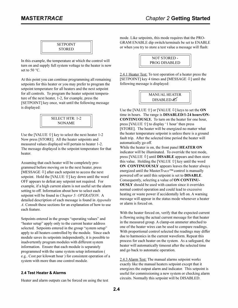
In this example, the temperature at which the control willturn on and supply full system voltage to the heater is nowset to 50 °C.
At this point you can continue programming all remainingsetpoints for this heater or you may prefer to program thesetpoint temperature for all heaters and the next setpointfor all controls. To program the heater setpoint tempera-ture of the next heater, 1-2, for example, press the[SETPOINT] key once, wait until the following messageis displayed:
SELECT HTR: 1-2NONAME
Use the [VALUE ñ] key to select the next heater 1-2Now press [STORE]. All the heater setpoints andmeasured values displayed will pertain to heater 1-2.The message displayed is the setpoint temperature for thatheater.
Assuming that each heater will be completely pro-grammed before moving on to the next heater, press[MESSAGE ò] after each setpoint to access the nextsetpoint. Hold the [VALUE ñ] key down until the wordOFF appears to defeat any setpoint not required. Forexample, if a high current alarm is not useful set the alarmsetting to off. Information about how to select eachsetpoint will be found in Chapter 5: OPERATION. Adetailed description of each message is found in AppendixA. Consult these sections for an explanation of how to useeach feature.
Setpoints entered in the groups �operating values� and�heater setup� apply only to the current heater addressselected. Setpoints entered in the group �system setup�apply to all heaters controlled by the module. Since eachmodule saves its setpoints independently, it is possible toinadvertently program modules with different systeminformation. Ensure that each module is separatelyprogrammed with the same system setup information (e.g.. Cost per kilowatt hour ) for consistent operation of asystem with more than one control module.
2.4 Test Heater & Alarms
Heater and alarm outputs can be forced on using the test
mode. Like setpoints, this mode requires that the PRO-GRAM ENABLE dip switch/terminals be set to ENABLEor when you try to store a test value a message will flash:
NOT STORED -PROG DISABLED
2.4.1 Heater Test: To test operation of a heater press the[SETPOINT] key 4 times and [MESSAGE ò] until thefollowing message is displayed:
MANUAL HEATERDISABLED?
Use the [VALUE ñ] or [VALUE ò] keys to set the ONtime in hours. The range is DISABLED/1-24 hours/ON-CONTINUOUSLY. To turn on the heater for one hour,press [VALUE ñ] to display �1 hour� then press[STORE]. The heater will be energized no matter whatthe heater temperature setpoint is unless there is a groundfault trip. After the selected time period the heater willautomatically go off.While the heater is on, the front panel HEATER ONindicator will be illuminated. To override the test mode,press [VALUE ò] until DISABLE appears and then storethis value. Holding the [VALUE ñ] key until the wordON CONTINUOUSLY appears leaves the heater alwaysenergized until the MasterTrace� control is manuallypowered off or until this setpoint is set to DISABLE.Consequently, selecting a value of ON CONTINU-OUSLY should be used with caution since it overridesnormal control operation and could lead to excessiveheating or waste power if accidentally left on. A warningmessage will appear in the status mode whenever a heateror alarm is forced on.
With the heater forced on, verify that the expected currentis flowing using the actual current message for that heaterin the measured group. A clamp-on ammeter atteched toone of the heater wires can be used to compare readings.With proportional control selected the readings may differdue to harmonics in the current waveform. Repeat thisprocess for each heater on the system. As a safeguard, theheater will automatically timeout after the selected timeand go back to automatic operation.
2.4.3 Alarm Test: The manual alarms setpoint worksexactly like the manual heaters setpoint except that itenergizes the output alarm and indicator. This setpoint isuseful for commissioning a new system or checking alarmcircuits. Normally this setpoint will be DISABLED.
2.5
MASTERTRACE Chapter 2 Getting Started
2.5 Monitor System Status
Now that the MasterTrace� control has been pro-grammed for a specific application, system status can bechecked. If no keys are pressed for the time specified inDISPLAY TIMEOUT in setpoints-system setup group ofmessages, the display will automatically go into thedefault message mode. In the System Status mode, thedisplay will show any alarms on the system. If desired thiscould be changed to a specific message later by repro-gramming the default message.
Measured values are accessed using the [MEASUREDVALUES] key. These are divided into 2 groups. Pressing[MEASURED VALUES] once accesses the group ofmessages that show current values of temperature currentetc. Pressing the [MEASURED VALUES] key twice willdisplay the statistics data such as minimum/maximumtemperature, power consumption, running hours etc.Unlike setpoints, measured values cannot be changedusing the [VALUE ñ] , [VALUE ò] or [STORE] keys.
Note: A summary of all measured messages is provided inAppendix B. Press the [MEASURED] key and [MES-SAGE ò] to view each measured value for the selectedheater.
All measured values displayed would be for heater 1-1. Ifyou want to look at heater 1-2, press the [VALUE ñ] keyto select heater 1-2 then press [STORE]. All measuredvalues will now be for this heater. Press [MESSAGE ò]to display the first measured value. Continue examiningeach value of interest by pressing the [MESSAGE ò] keyand referring to Chapter 5: OPERATION and AppendixB.
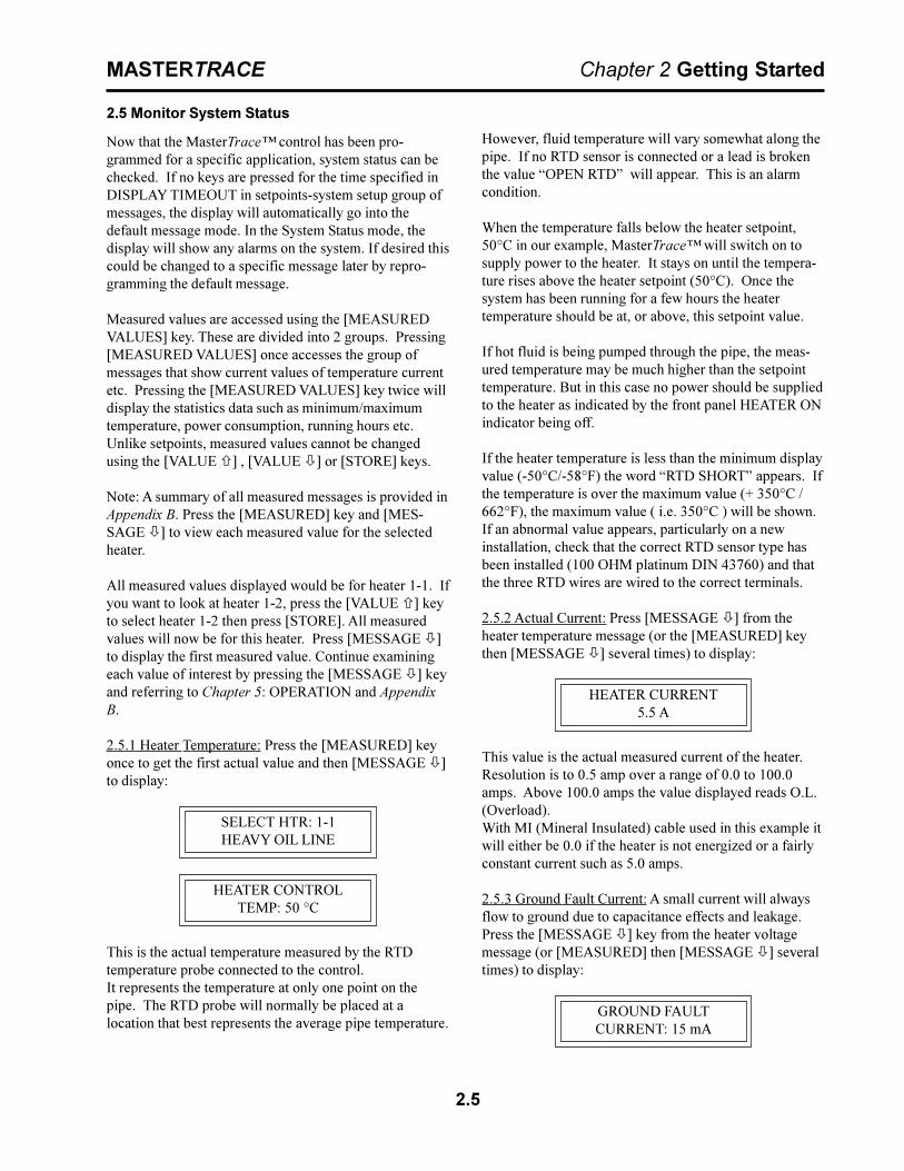
2.5.1 Heater Temperature: Press the [MEASURED] keyonce to get the first actual value and then [MESSAGE ò]to display:
SELECT HTR: 1-1HEAVY OIL LINE
HEATER CONTROLTEMP: 50 °C
This is the actual temperature measured by the RTDtemperature probe connected to the control.It represents the temperature at only one point on thepipe. The RTD probe will normally be placed at alocation that best represents the average pipe temperature.
However, fluid temperature will vary somewhat along thepipe. If no RTD sensor is connected or a lead is brokenthe value �OPEN RTD� will appear. This is an alarmcondition.
When the temperature falls below the heater setpoint,50°C in our example, MasterTrace� will switch on tosupply power to the heater. It stays on until the tempera-ture rises above the heater setpoint (50°C). Once thesystem has been running for a few hours the heatertemperature should be at, or above, this setpoint value.
If hot fluid is being pumped through the pipe, the meas-ured temperature may be much higher than the setpointtemperature. But in this case no power should be suppliedto the heater as indicated by the front panel HEATER ONindicator being off.
If the heater temperature is less than the minimum displayvalue (-50°C/-58°F) the word �RTD SHORT� appears. Ifthe temperature is over the maximum value (+ 350°C /662°F), the maximum value ( i.e. 350°C ) will be shown.If an abnormal value appears, particularly on a newinstallation, check that the correct RTD sensor type hasbeen installed (100 OHM platinum DIN 43760) and thatthe three RTD wires are wired to the correct terminals.
2.5.2 Actual Current: Press [MESSAGE ò] from theheater temperature message (or the [MEASURED] keythen [MESSAGE ò] several times) to display:
HEATER CURRENT5.5 A
This value is the actual measured current of the heater.Resolution is to 0.5 amp over a range of 0.0 to 100.0amps. Above 100.0 amps the value displayed reads O.L.(Overload).With MI (Mineral Insulated) cable used in this example itwill either be 0.0 if the heater is not energized or a fairlyconstant current such as 5.0 amps.
2.5.3 Ground Fault Current: A small current will alwaysflow to ground due to capacitance effects and leakage.Press the [MESSAGE ò] key from the heater voltagemessage (or [MEASURED] then [MESSAGE ò] severaltimes) to display:
GROUND FAULTCURRENT: 15 mA

2.6
MASTERTRACE Chapter 2 Getting Started
In this example, any value above 20mA would cause analarm and if a ground fault current above 30mA weredetected, MasterTrace� would remove power to theheater. If the heater is off, the value displayed would be�0�. For values over 15 mA, check the system forinsulation leakage problems.
All actual values have now been checked.
2.5.4 Statistical Data: In addition to actual values that arepresent, such as current and temperature, MasterTrace�continuously gathers and computes historic informationabout the heat tracing system to determine cost of opera-tion, utilization, trends etc. This can be quite useful inspotting potential problems or in designing similarsystems for other applications. Information is stored forthe last 24 hours to give an idea of current usage.
Pressing the [MESSAGE ò] key from the measured valuemessages just displayed will take you to the statisticsvalues group. A short-cut is to press the [MEASURED]key twice to display the first message in this group.Either way displays a brief message to indicate the start ofthe statistics page followed by the first value message:
MEASURED:STATISTICS
Since this is a new installation any random data should becleared. Press [MESSAGE ò] in this group until themessage appears:
RESETSTATISTICS: YES??
Reset statistics for a new measurement interval. Data canbe read or cleared at any time to provide the most usefulinformation. MasterTrace� will keep track of when themeasurement interval started. See Chapter 5: Operationand Appendix B for a complete description of how data isgathered and application ideas.
Important note:If you clear statistics using an ML100, the statistics forall heaters will be cleared. However, if you clear statisticsusing MR100, only the statistics of the selected heater iscleared.
This completes setpoint programming and system testing.Set the PROGRAM ENABLE dip switch/terminals toDISABLE to prevent accidental setpoint changes ortampering. By following this sequence and messageexplanation it should be fairly easy to install a similarcontrol application. Refer to Appendix A and Appendix Bfor further details.
As the system is used, some setpoints may need adjusting.For example, frequent low temperature alarms mightindicate that the setpoint value was set too close to normalheater temperature swings and needs to be lowered.

3.1
MASTERTRACE Chapter 3 Product Description
3 Product Description
3.1 Introduction
Electric heat tracing control schemes have generally usedsome combination of mechanical thermostats, custombuilt control panels or programmable controls to providethe required level of control, monitoring and alarmfunctions. Budgetary constraints usually limit the degreeof system fault monitoring to less than optimal levels.This results in periodic costly process shutdowns due toprocess or hardware malfunctions. Equipment reliabilityconcerns often force plant procedures to include annualthermostat performance checks to ensure that the deviceis still operating as intended. This can be a tedious,labour intensive job.
The MasterTrace� heat tracing system is a compatiblefamily of electronic controls that uses state of the arttechnology to give complete control and central monitor-ing of electric heat tracing systems. MasterTrace� can beused with MI, self-regulating and constant wattage cable.Individual smart controls mounted near to the pipe beingtraced can communicate with a single master unit to givecomplete system monitoring and control from a conven-ient location.
Continuous process and hardware monitoring with alarmsfor the complete system at a central point eliminates theneed for annual maintenance checks. Overall system costis lower than custom panels that have far less capabilitydue to the many standard features incorporated into eachcontrol.
Each heater point is monitored by a control mounted nearthe pipe being traced. Up to 300 points can be monitoredby a single master conveniently located to allow quicksystem monitoring and fault diagnosis. A second RS485port can be used for communication between controls andcentralized monitoring. Each local control is completelyindependent and will continue to function if the masterfails or if the communication link fails. This ensuresmaximum reliability and minimizes vulnerability in theevent of a hardware failure. Additional points can beadded at any time as easily as a mechanical thermostatcan be installed. Unlike control schemes using program-mable controllers, no software development is required.The complete system is operational as soon as it isinstalled.
To ensure that the MasterTrace� heat tracing system willcontinue to meet the needs of plants as they upgrade tofully automated operation, an additional data highway canbe implemented using the second RS485 port. By con-necting controls to a programmable controller that is tiedinto a central plant computer, alarms caused by heattracing malfunctions can immediately be flagged in acentral control location. The complete system can bemonitored and problem descriptions can be received forfast fault diagnosis and repair. In addition, the setpointsof any remote control can be altered by the master control(MR100) or a central computer (MC100). Heaters can bemanually forced on and any pipe temperature can be read.
Figure 3.1 MasterTrace� System Concept
3.2
MASTERTRACE Chapter 3 Product Description
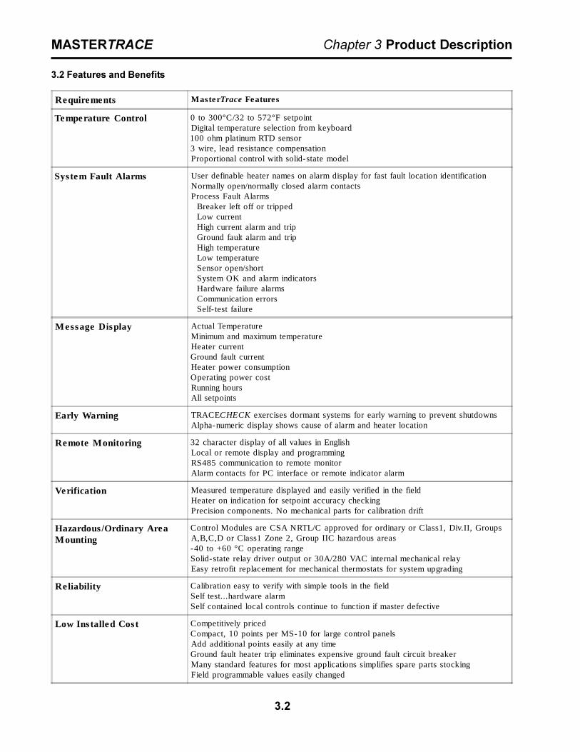
Requirements MasterTrace Features
Temperature Control 0 to 300°C/32 to 572°F setpointDigital temperature selection from keyboard100 ohm platinum RTD sensor3 wire, lead resistance compensationProportional control with solid-state model
System Fault Alarms User definable heater names on alarm display for fast fault location identificationNormally open/normally closed alarm contactsProcess Fault Alarms Breaker left off or tripped Low current High current alarm and trip Ground fault alarm and trip High temperature Low temperature Sensor open/short System OK and alarm indicators Hardware failure alarms Communication errors Self- test failure
Message Display Actual TemperatureMinimum and maximum temperatureHeater currentGround fault currentHeater power consumptionOperating power costRunning hoursAll setpoints
Early Warning TRACECHECK exercises dormant systems for early warning to prevent shutdownsAlpha-numeric display shows cause of alarm and heater location
Remote Monitoring 32 character display of all values in EnglishLocal or remote display and programmingRS485 communication to remote monitorAlarm contacts for PC interface or remote indicator alarm
Verification Measured temperature displayed and easily verified in the fieldHeater on indication for setpoint accuracy checkingPrecision components. No mechanical parts for calibration drift
Hazardous/Ordinary AreaMounting
Control Modules are CSA NRTL/C approved for ordinary or Class1, Div.II, GroupsA,B,C,D or Class1 Zone 2, Group IIC hazardous areas-40 to +60 °C operating rangeSolid-state relay driver output or 30A/280 VAC internal mechanical relayEasy retrofit replacement for mechanical thermostats for system upgrading
Reliability Calibration easy to verify with simple tools in the fieldSelf test...hardware alarmSelf contained local controls continue to function if master defective
Low Installed Cost Competitively pricedCompact, 10 points per MS-10 for large control panelsAdd additional points easily at any timeGround fault heater trip eliminates expensive ground fault circuit breakerMany standard features for most applications simplifies spare parts stockingField programmable values easily changed
3.2 Features and Benefits
3.3
MASTERTRACE Chapter 3 Product Description
3.3 Control Module Specifications
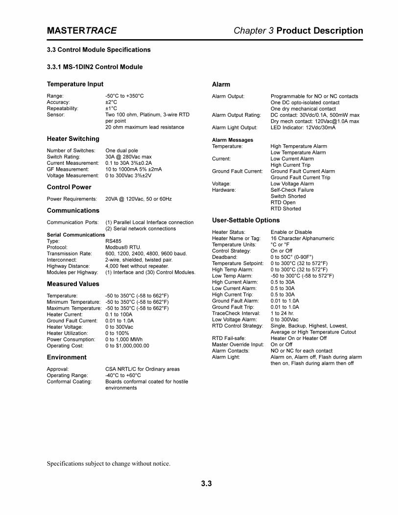
3.3.1 MS-1DIN2 Control Module
Temperature Input
Range: -50°C to +350°CAccuracy: ±2°CRepeatability: ±1°CSensor: Two 100 ohm, Platinum, 3-wire RTD
per point20 ohm maximum lead resistance
Heater Switching
Number of Switches: One dual poleSwitch Rating: 30A @ 280Vac maxCurrent Measurement: 0.1 to 30A 3%±0.2AGF Measurement: 10 to 1000mA 5% ±2mAVoltage Measurement: 0 to 300Vac 3%±2V
Control Power
Power Requirements: 20VA @ 120Vac, 50 or 60Hz
Communications
Communication Ports: (1) Parallel Local Interface connection(2) Serial network connections
Serial CommunicationsType: RS485Protocol: Modbus® RTU.Transmission Rate: 600, 1200, 2400, 4800, 9600 baud.Interconnect: 2-wire, shielded, twisted pair.Highway Distance: 4,000 feet without repeater.Modules per Highway: (1) Interface and (30) Control Modules.
Measured Values
Temperature: -50 to 350°C (-58 to 662°F)Minimum Temperature: -50 to 350°C (-58 to 662°F)Maximum Temperature: -50 to 350°C (-58 to 662°F)Heater Current: 0.1 to 100AGround Fault Current: 0.01 to 1.0AHeater Voltage: 0 to 300VacHeater Utilization: 0 to 100%Power Consumption: 0 to 1,000 MWhOperating Cost: 0 to $1,000,000.00
Environment
Approval: CSA NRTL/C for Ordinary areasOperating Range: -40°C to +60°CConformal Coating: Boards conformal coated for hostile
environments
Alarm
Alarm Output: Programmable for NO or NC contactsOne DC opto-isolated contactOne dry mechanical contact
Alarm Output Rating: DC contact: 30Vdc/0.1A, 500mW maxDry mech contact: [email protected] max
Alarm Light Output: LED Indicator: 12Vdc/30mA
Alarm MessagesTemperature: High Temperature Alarm
Low Temperature AlarmCurrent: Low Current Alarm
High Current TripGround Fault Current: Ground Fault Current Alarm
Ground Fault Current TripVoltage: Low Voltage AlarmHardware: Self-Check Failure
Switch ShortedRTD OpenRTD Shorted
User-Settable Options
Heater Status: Enable or DisableHeater Name or Tag: 16 Character AlphanumericTemperature Units: °C or °FControl Strategy: On or OffDeadband: 0 to 50C° (0-90F°)Temperature Setpoint: 0 to 300°C (32 to 572°F)High Temp Alarm: 0 to 300°C (32 to 572°F)Low Temp Alarm: -50 to 300°C (-58 to 572°F)High Current Alarm: 0.5 to 30ALow Current Alarm: 0.5 to 30AHigh Current Trip: 0.5 to 30AGround Fault Alarm: 0.01 to 1.0AGround Fault Trip: 0.01 to 1.0ATraceCheck Interval: 1 to 24 hr.Low Voltage Alarm: 0 to 300VacRTD Control Strategy: Single, Backup, Highest, Lowest,
Average or High Temperature CutoutRTD Fail-safe: Heater On or Heater OffMaster Override Input: On or OffAlarm Contacts: NO or NC for each contactAlarm Light: Alarm on, Alarm off, Flash during alarm
then on, Flash during alarm then off
Specifications subject to change without notice.

3.4
MASTERTRACE Chapter 3 Product Description
3.3.2 MS-1DXH0 Control Module
Temperature Input
Range: -50°C to +350°CAccuracy: ±2°CRepeatability: ±1°CSensor: Two 100 ohm, Platinum, 3-wire RTD
per point20 ohm maximum lead resistance
Current Input
Range: 0.1A to 100AAccuracy: 3%±0.2ASensor: One current transformer
GF Input
Range: 10mA to 1000mAAccuracy: 5%±2mASensor: One current transformer
Voltage Input
Range: 0Vac to 300VacAccuracy: 3%±2VSensor: One voltage transformer
Heater Switching
No. of SSR Outputs: OneSSR Output Rating: 12Vdc@15mA max output for driving
external solid-state relays600Vac@100A max.GF CT will allow two conductors of O.D.0.35� max.
Heater Configuration: Single Phase
Control Power
Power Requirements: 15VA @ 120Vac, 50 or 60Hz
Communications
Communication Ports: (1) Parallel Local Interface connection(2) Serial network connections
Serial CommunicationsType: RS485Protocol: Modbus® RTU.Transmission Rate: 1200, 2400, 4800, 9600 baud.Interconnect: 2-wire, shielded, twisted pair.Highway Distance: 4,000 feet without repeater.Modules per Highway: (1) Interface and (30) Control Modules.
Measured Values
Temperature: -50 to 350°C (-58 to 662°F)Minimum Temperature: -50 to 350°C (-58 to 662°F)Maximum Temperature: -50 to 350°C (-58 to 662°F)Heater Current: 0.1 to 100AHeater Percent Power 0 to 100%Ground Fault Current: 0.01 to 1.0AHeater Voltage: 0 to 300VacHeater Utilization: 0 to 100%Power Consumption: 0 to 1,000 MWhOperating Cost: 0 to $1,000,000.00
Environment
Approval: CSA NRTL/CClass1, Div.II, Groups A,B,C,DClass1 Zone 2, Group IIC
Operating Range: -40°C to +60°CConformal Coating: Boards conformal coated for hostile
environments
Alarm
Alarm Output: Programmable for NO or NC contactsOne DC opto-isolated contactOne dry mechanical contact
Alarm Output Rating:Hazardous Areas: DC contact: 30Vdc/0.1A, 500mW max
Dry mech contact: 30Vdc@10mA maxOrdinary Areas: DC contact: 30Vdc/0.1A, 500mW max
Dry mech contact: [email protected] maxAlarm Light Output: LED Indicator: 12Vdc/30mA
Alarm MessagesTemperature: High Temperature Alarm
Low Temperature AlarmCurrent: High Current Alarm
Low Current AlarmHigh Current Trip
Ground Fault Current: Ground Fault Current AlarmGround Fault Current Trip
Voltage: Low Voltage AlarmHardware: Self-Check Failure
Switch ShortedRTD OpenRTD Shorted
User-Settable Options
Heater Status: Enable or DisableHeater Name or Tag: 16 Character AlphanumericTemperature Units: °C or °FControl Strategy: On-Off or ProportionalDeadband: 0 to 50C° (0-90F°)PowerLimit: 0.5 to100ATemperature Setpoint: 0 to 300°C (32 to 572°F)High Temp Alarm: 0 to 300°C (32 to 572°F)Low Temp Alarm: -50 to 300°C (-58 to 572°F)High Current Alarm: 0.5 to 100ALow Current Alarm: 0.5 to 100AHigh Current Trip: 0.5 to 100AGround Fault Alarm: 0.01 to 1.0AGround Fault Trip: 0.01 to 1.0ATraceCheck Interval: 1 to 24 hr.Low Voltage Alarm: 0 to 300VacRTD Control Strategy: Single, Backup, Highest, Lowest,
Average or High Temperature CutoutRTD Fail-safe: Heater On or Heater OffMaster Override Input: On or OffAlarm Contacts: NO or NC for each contactAlarm Light: Alarm on, Alarm off, Flash during alarm
then on, Flash during alarm then off
Specifications subject to change without notice.

3.5
MASTERTRACE Chapter 3 Product Description
3.3.3 MS-1TXH0 Control Module
Temperature Input
Range: -50°C to +350°CAccuracy: ±2°CRepeatability: ±1°CSensor: Two 100 ohm, Platinum, 3-wire RTD
per point20 ohm maximum lead resistance
Current Input
Range: 0.1A to 100AAccuracy: 3%±0.2ASensor: Three current transformers
GF Input
Range: 10mA to 1000mAAccuracy: 5%±2mASensor: One current transformer
Heater Switching
No. of SSR Outputs: OneSSR Output Rating: 12Vdc@15mA max output for driving
external solid-state relays600Vac@100A max.GF CT will allow three conductors ofO.D 0.32� max.
Heater Configuration: Three Phase
Control Power
Power Requirements: 15VA @ 120Vac, 50 or 60Hz
Communications
Communication Ports: (1) Parallel Local Interface connection(2) Serial network connections
Serial CommunicationsType: RS485Protocol: Modbus® RTU.Transmission Rate: 600, 1200, 2400, 4800, 9600 baud.Interconnect: 2-wire, shielded, twisted pair.Highway Distance: 4,000 feet without repeater.Modules per Highway: (1) Interface and (30) Control Modules.
Measured Values
Temperature: -50 to 350°C (-58 to 662°F)Minimum Temperature: -50 to 350°C (-58 to 662°F)Maximum Temperature: -50 to 350°C (-58 to 662°F)Heater Current: 0.1 to 100AHeater Percent Power: 0 to 100%Ground Fault Current: 0.01 to 1.0AHeater Utilization: 0 to 100%Power Consumption: 0 to 1,000 MWhOperating Cost: 0 to $1,000,000.00
Environment
Approval: CSA NRTL/CClass1, Div.II, Groups A,B,C,DClass1 Zone 2, Group IIC
Operating Range: -40°C to +60°CConformal Coating: Boards conformal coated for hostile
environments
Alarm
Alarm Output: Programmable for NO or NC contactsOne DC opto-isolated contactOne dry mechanical contact
Alarm Output Rating:Hazardous Areas: DC contact: 30Vdc/0.1A, 500mW max
Dry mech contact: 30Vdc@10mA maxOrdinary Areas: DC contact: 30Vdc/0.1A, 500mW max
Dry mech contact: [email protected] maxAlarm Light Output: LED Indicator: 12Vdc/30mA
Alarm MessagesTemperature: High Temperature Alarm
Low Temperature AlarmCurrent: High Current Alarm
Low Current AlarmHigh Current Trip
Ground Fault Current: Ground Fault Current AlarmGround Fault Current Trip
Hardware: Self-Check FailureSwitch ShortedRTD OpenRTD Shorted
User-Settable Options
Heater Status: Enable or DisableHeater Name or Tag: 16 Character AlphanumericTemperature Units: °C or °FControl Strategy: On-Off or ProportionalDeadband: 0 to 50C° (0-90F°)PowerLimit: 0.5 to 100ATemperature Setpoint: 0 to 300°C (32 to 572°F)High Temp Alarm: 0 to 300°C (32 to 572°F)Low Temp Alarm: -50 to 300°C (-58 to 572°F)High Current Alarm: 0.5 to 100ALow Current Alarm: 0.5 to 100AHigh Current Trip: 0.5 to 100AGround Fault Alarm: 0.01 to 1.0AGround Fault Trip: 0.01 to 1.0ATraceCheck Interval: 1 to 24 hr.RTD Control Strategy: Single, Backup, Highest, Lowest,
Average or High Temperature CutoutRTD Fail-safe: Heater On or Heater OffMaster Override Input: On or OffAlarm Contacts: NO or NC for each contactAlarm Light: Alarm on, Alarm off, Flash during alarm
then on, Flash during alarm then off
Specifications subject to change without notice.
3.6
MASTERTRACE Chapter 3 Product Description
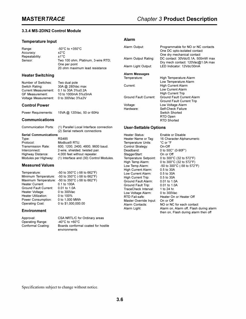
3.3.4 MS-2DIN2 Control Module
Temperature Input
Range: -50°C to +350°CAccuracy: ±2°CRepeatability: ±1°CSensor: Two 100 ohm, Platinum, 3-wire RTD;
One per point20 ohm maximum lead resistance
Heater Switching
Number of Switches: Two dual poleSwitch Rating: 30A @ 280Vac maxCurrent Measurement: 0.1 to 30A 3%±0.2AGF Measurement: 10 to 1000mA 5%±5mAVoltage Measurement: 0 to 300Vac 3%±2V
Control Power
Power Requirements: 15VA @ 120Vac, 50 or 60Hz
Communications
Communication Ports: (1) Parallel Local Interface connection(2) Serial network connections
Serial CommunicationsType: RS485Protocol: Modbus® RTU.Transmission Rate: 600, 1200, 2400, 4800, 9600 baud.Interconnect: 2-wire, shielded, twisted pair.Highway Distance: 4,000 feet without repeater.Modules per Highway: (1) Interface and (30) Control Modules.
Measured Values
Temperature: -50 to 350°C (-58 to 662°F)Minimum Temperature: -50 to 350°C (-58 to 662°F)Maximum Temperature: -50 to 350°C (-58 to 662°F)Heater Current: 0.1 to 100AGround Fault Current: 0.01 to 1.0AHeater Voltage: 0 to 300VacHeater Utilization: 0 to 100%Power Consumption: 0 to 1,000 MWhOperating Cost: 0 to $1,000,000.00
Environment
Approval: CSA NRTL/C for Ordinary areasOperating Range: -40°C to +60°CConformal Coating: Boards conformal coated for hostile
environments
Alarm
Alarm Output: Programmable for NO or NC contactsOne DC opto-isolated contactOne dry mechanical contact
Alarm Output Rating: DC contact: 30Vdc/0.1A, 500mW maxDry mech contact: [email protected] max
Alarm Light Output: LED Indicator: 12Vdc/30mA
Alarm MessagesTemperature: High Temperature Alarm
Low Temperature AlarmCurrent: High Current Alarm
Low Current AlarmHigh Current Trip
Ground Fault Current: Ground Fault Current AlarmGround Fault Current Trip
Voltage: Low Voltage AlarmHardware: Self-Check Failure
Switch ShortedRTD OpenRTD Shorted
User-Settable Options
Heater Status: Enable or DisableHeater Name or Tag: 16 Character AlphanumericTemperature Units: °C or °FControl Strategy: On-OffDeadband: 0 to 50C° (0-90F°)StaggerStart: On or OffTemperature Setpoint: 0 to 300°C (32 to 572°F)High Temp Alarm: 0 to 300°C (32 to 572°F)Low Temp Alarm: -50 to 300°C (-58 to 572°F)High Current Alarm: 0.5 to 30ALow Current Alarm: 0.5 to 30AHigh Current Trip: 0.5 to 30AGround Fault Alarm: 0.01 to 1.0AGround Fault Trip: 0.01 to 1.0ATraceCheck Interval: 1 to 24 hr.Low Voltage Alarm: 0 to 300VacRTD Fail-safe: Heater On or Heater OffMaster Override Input: On or OffAlarm Contacts: NO or NC for each contactAlarm Light: Alarm on, Alarm off, Flash during alarm
then on, Flash during alarm then off
Specifications subject to change without notice.
3.7
MASTERTRACE Chapter 3 Product Description
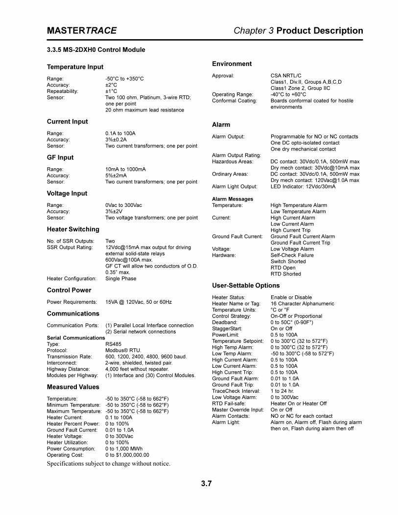
3.3.5 MS-2DXH0 Control Module
Temperature Input
Range: -50°C to +350°CAccuracy: ±2°CRepeatability: ±1°CSensor: Two 100 ohm, Platinum, 3-wire RTD;
one per point20 ohm maximum lead resistance
Current Input
Range: 0.1A to 100AAccuracy: 3%±0.2ASensor: Two current transformers; one per point
GF Input
Range: 10mA to 1000mAAccuracy: 5%±2mASensor: Two current transformers; one per point
Voltage Input
Range: 0Vac to 300VacAccuracy: 3%±2VSensor: Two voltage transformers; one per point
Heater Switching
No. of SSR Outputs: TwoSSR Output Rating: 12Vdc@15mA max output for driving
external solid-state relays600Vac@100A max.GF CT will allow two conductors of O.D.0.35� max.
Heater Configuration: Single Phase
Control Power
Power Requirements: 15VA @ 120Vac, 50 or 60Hz
Communications
Communication Ports: (1) Parallel Local Interface connection(2) Serial network connections
Serial CommunicationsType: RS485Protocol: Modbus® RTU.Transmission Rate: 600, 1200, 2400, 4800, 9600 baud.Interconnect: 2-wire, shielded, twisted pair.Highway Distance: 4,000 feet without repeater.Modules per Highway: (1) Interface and (30) Control Modules.
Measured Values
Temperature: -50 to 350°C (-58 to 662°F)Minimum Temperature: -50 to 350°C (-58 to 662°F)Maximum Temperature: -50 to 350°C (-58 to 662°F)Heater Current: 0.1 to 100AHeater Percent Power: 0 to 100%Ground Fault Current: 0.01 to 1.0AHeater Voltage: 0 to 300VacHeater Utilization: 0 to 100%Power Consumption: 0 to 1,000 MWhOperating Cost: 0 to $1,000,000.00
Environment
Approval: CSA NRTL/CClass1, Div.II, Groups A,B,C,DClass1 Zone 2, Group IIC
Operating Range: -40°C to +60°CConformal Coating: Boards conformal coated for hostile
environments
Alarm
Alarm Output: Programmable for NO or NC contactsOne DC opto-isolated contactOne dry mechanical contact
Alarm Output Rating:Hazardous Areas: DC contact: 30Vdc/0.1A, 500mW max
Dry mech contact: 30Vdc@10mA maxOrdinary Areas: DC contact: 30Vdc/0.1A, 500mW max
Dry mech contact: [email protected] maxAlarm Light Output: LED Indicator: 12Vdc/30mA
Alarm MessagesTemperature: High Temperature Alarm
Low Temperature AlarmCurrent: High Current Alarm
Low Current AlarmHigh Current Trip
Ground Fault Current: Ground Fault Current AlarmGround Fault Current Trip
Voltage: Low Voltage AlarmHardware: Self-Check Failure
Switch ShortedRTD OpenRTD Shorted
User-Settable Options
Heater Status: Enable or DisableHeater Name or Tag: 16 Character AlphanumericTemperature Units: °C or °FControl Strategy: On-Off or ProportionalDeadband: 0 to 50C° (0-90F°)StaggerStart: On or OffPowerLimit: 0.5 to 100ATemperature Setpoint: 0 to 300°C (32 to 572°F)High Temp Alarm: 0 to 300°C (32 to 572°F)Low Temp Alarm: -50 to 300°C (-58 to 572°F)High Current Alarm: 0.5 to 100ALow Current Alarm: 0.5 to 100AHigh Current Trip: 0.5 to 100AGround Fault Alarm: 0.01 to 1.0AGround Fault Trip: 0.01 to 1.0ATraceCheck Interval: 1 to 24 hr.Low Voltage Alarm: 0 to 300VacRTD Fail-safe: Heater On or Heater OffMaster Override Input: On or OffAlarm Contacts: NO or NC for each contactAlarm Light: Alarm on, Alarm off, Flash during alarm
then on, Flash during alarm then off
Specifications subject to change without notice.

3.8
MASTERTRACE Chapter 3 Product Description
3.3.6 MS-5ADIN2 Control Module
Temperature Input
Range: -50°C to +350°CAccuracy: ±2°CRepeatability: ±1°CSensor: Ten 100 ohm, Platinum, 3-wire RTD;
two per point20 ohm maximum lead resistance
Heater Switching
Number of Switches: Five dual poleSwitch Rating: 30A @ 280Vac maxCurrent Measurement: 0.1 to 30A 3%±0.2AGF Measurement: 10 to 1000mA 5%±2mA
Ground Fault
Maximum Trip Time: 13.7 seconds
Control Power
Power Requirements: 35VA @ 120Vac, 50 or 60Hz
Communications
Communication Ports: (1) Parallel Local Interface connection(2) Serial network connections
Serial CommunicationsType: RS485Protocol: Modbus® RTU.Transmission Rate: 600, 1200, 2400, 4800, 9600 baud.Interconnect: 2-wire, shielded, twisted pair.Highway Distance: 4,000 feet without repeater.Modules per Highway: (1) Interface and (30) Control Modules.
Measured Values
Temperature: -50 to 350°C (-58 to 662°F)Minimum Temperature: -50 to 350°C (-58 to 662°F)Maximum Temperature: -50 to 350°C (-58 to 662°F)Heater Current: 0.1 to 100AGround Fault Current: 0.01 to 1.0AHeater Utilization: 0 to 100%Power Consumption: 0 to 1,000 MWhOperating Cost: 0 to $1,000,000.00
Environment
Approval: CSA NRTL/C for Ordinary areasOperating Range: -40°C to +60°CConformal Coating: Boards conformal coated for hostile
environments
Alarm
Alarm Output: Programmable for NO or NC contactsOne DC opto-isolated contactOne dry mechanical contact
Alarm Output Rating: DC contact: 30Vdc/0.1A, 500mW maxDry mech contact: [email protected] max
Alarm Light Output: LED Indicator: 12Vdc/30mA
Alarm MessagesTemperature: High Temperature Alarm
Low Temperature AlarmCurrent: High Current Alarm
Low Current AlarmHigh Current Trip
Ground Fault Current: Ground Fault Current AlarmGround Fault Current Trip
Hardware: Self-Check FailureSwitch ShortedRTD OpenRTD Shorted
User-Settable Options
Heater Status: Enable or DisableHeater Name or Tag: 16 Character AlphanumericTemperature Units: °C or °FControl Strategy: On-OffDeadband: 0 to 50C° (0-90F°)StaggerStart: On or OffTemperature Setpoint: 0 to 300°C (32 to 572°F)High Temp Alarm: 0 to 300°C (32 to 572°F)Low Temp Alarm: -50 to 300°C (-58 to 572°F)High Current Alarm: 0.5 to 30ALow Current Alarm: 0.5 to 30AHigh Current Trip: 0.5 to 30AGround Fault Alarm: 0.01 to 1.0AGround Fault Trip: 0.01 to 1.0ATraceCheck Interval: 1 to 24 hr.RTD Control Strategy: Single, Backup, Highest, Lowest,
Average or High Temperature CutoutRTD Fail-safe: Heater On or Heater OffMaster Override Input: On or OffAlarm Contacts: NO or NC for each contactAlarm Light: Alarm on, Alarm off, Flash during alarm
then on, Flash during alarm then offGF Test: 1 to 24hrs, test now
Specifications subject to change without notice.

3.9
MASTERTRACE Chapter 3 Product Description
3.3.7 MS-5ADXH0 Control Module
Temperature Input
Range: -50°C to +350°CAccuracy: ±2°CRepeatability: ±1°CSensor: Ten 100 ohm, Platinum, 3-wire RTD;
two per point20 ohm maximum lead resistance
Current Input
Range: 0.1A to 100AAccuracy: 3%±0.2ASensor: Five current transformers; one per point
GF Input
Range: 10mA to 1000mAAccuracy: 5%±2mASensor: Five current transformers; one per pointMaximum Trip Time: 14.1 seconds
Heater Switching
No. of SSR Outputs: FiveSSR Output Rating: 12Vdc@15mA max output for driving
external solid-state relays600Vac@100A max.GF CT will allow two conductors of O.D.0.35� max.
Heater Configuration: Single Phase
Control Power
Power Requirements: 15VA @ 120Vac, 50 or 60Hz
Communications
Communication Ports: (1) Parallel Local Interface connection(2) Serial network connections
Serial CommunicationsType: RS485Protocol: Modbus® RTU.Transmission Rate: 600, 1200, 2400, 4800, 9600 baud.Interconnect: 2-wire, shielded, twisted pair.Highway Distance: 4,000 feet without repeater.Modules per Highway: (1) Interface and (30) Control Modules.
Measured Values
Temperature: -50 to 350°C (-58 to 662°F)Minimum Temperature: -50 to 350°C (-58 to 662°F)Maximum Temperature: -50 to 350°C (-58 to 662°F)Heater Current: 0.1 to 100AHeater Percent Power: 0 to 100%Ground Fault Current: 0.01 to 1.0AHeater Utilization: 0 to 100%Power Consumption: 0 to 1,000 MWhOperating Cost: 0 to $1,000,000.00
Environment
Approval: CSA NRTL/CClass1, Div.II, Groups A,B,C,DClass1 Zone 2, Group IIC
Operating Range: -40°C to +60°CConformal Coating: Boards conformal coated for hostile
environments
Alarm
Alarm Output: Programmable for NO or NC contactsOne DC opto-isolated contactOne dry mechanical contact
Alarm Output Rating:Hazardous Areas: DC contact: 30Vdc/0.1A, 500mW max
Dry mech contact: 30Vdc@10mA maxOrdinary Areas: DC contact: 30Vdc/0.1A, 500mW max
Dry mech contact: [email protected] maxAlarm Light Output: LED Indicator: 12Vdc/30mA
Alarm MessagesTemperature: High Temperature Alarm
Low Temperature AlarmCurrent: High Current Alarm
Low Current AlarmHigh Current Trip
Ground Fault Current: Ground Fault Current AlarmGround Fault Current Trip
Hardware: Self-Check FailureSwitch ShortedRTD OpenRTD Shorted
User-Settable Options
Heater Status: Enable or DisableHeater Name or Tag: 16 Character AlphanumericTemperature Units: °C or °FControl Strategy: On-Off or ProportionalDeadband: 0 to 50C° (0-90F°)StaggerStart: On or OffPowerLimit: 0.5 to 100ATemperature Setpoint: 0 to 300°C (32 to 572°F)High Temp Alarm: 0 to 300°C (32 to 572°F)Low Temp Alarm: -50 to 300°C (-58 to 572°F)High Current Alarm: 0.5 to 100ALow Current Alarm: 0.5 to 100AHigh Current Trip: 0.5 to 100AGround Fault Alarm: 0.01 to 1.0AGround Fault Trip: 0.01 to 1.0ATraceCheck Interval: 1 to 24 hr.RTD Control Strategy: Single, Backup, Highest, Lowest,
Average or High Temperature CutoutRTD Fail-safe: Heater On or Heater OffMaster Override Input: On or OffAlarm Contacts: NO or NC for each contactAlarm Light: Alarm on, Alarm off, Flash during alarm
then on, Flash during alarm then offGF Test: 1 to 24hrs, test now
Specifications subject to change without notice.
3.10
MASTERTRACE Chapter 3 Product Description
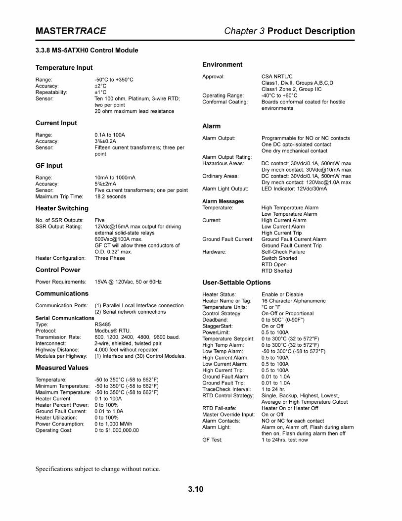
3.3.8 MS-5ATXH0 Control Module
Temperature Input
Range: -50°C to +350°CAccuracy: ±2°CRepeatability: ±1°CSensor: Ten 100 ohm, Platinum, 3-wire RTD;
two per point20 ohm maximum lead resistance
Current Input
Range: 0.1A to 100AAccuracy: 3%±0.2ASensor: Fifteen current transformers; three per
point
GF Input
Range: 10mA to 1000mAAccuracy: 5%±2mASensor: Five current transformers; one per pointMaximum Trip Time: 18.2 seconds
Heater Switching
No. of SSR Outputs: FiveSSR Output Rating: 12Vdc@15mA max output for driving
external solid-state relays600Vac@100A max.GF CT will allow three conductors ofO.D. 0.32� max.
Heater Configuration: Three Phase
Control Power
Power Requirements: 15VA @ 120Vac, 50 or 60Hz
Communications
Communication Ports: (1) Parallel Local Interface connection(2) Serial network connections
Serial CommunicationsType: RS485Protocol: Modbus® RTU.Transmission Rate: 600, 1200, 2400, 4800, 9600 baud.Interconnect: 2-wire, shielded, twisted pair.Highway Distance: 4,000 feet without repeater.Modules per Highway: (1) Interface and (30) Control Modules.
Measured Values
Temperature: -50 to 350°C (-58 to 662°F)Minimum Temperature: -50 to 350°C (-58 to 662°F)Maximum Temperature: -50 to 350°C (-58 to 662°F)Heater Current: 0.1 to 100AHeater Percent Power: 0 to 100%Ground Fault Current: 0.01 to 1.0AHeater Utilization: 0 to 100%Power Consumption: 0 to 1,000 MWhOperating Cost: 0 to $1,000,000.00
Environment
Approval: CSA NRTL/CClass1, Div.II, Groups A,B,C,DClass1 Zone 2, Group IIC
Operating Range: -40°C to +60°CConformal Coating: Boards conformal coated for hostile
environments
Alarm
Alarm Output: Programmable for NO or NC contactsOne DC opto-isolated contactOne dry mechanical contact
Alarm Output Rating:Hazardous Areas: DC contact: 30Vdc/0.1A, 500mW max
Dry mech contact: 30Vdc@10mA maxOrdinary Areas: DC contact: 30Vdc/0.1A, 500mW max
Dry mech contact: [email protected] maxAlarm Light Output: LED Indicator: 12Vdc/30mA
Alarm MessagesTemperature: High Temperature Alarm
Low Temperature AlarmCurrent: High Current Alarm
Low Current AlarmHigh Current Trip
Ground Fault Current: Ground Fault Current AlarmGround Fault Current Trip
Hardware: Self-Check FailureSwitch ShortedRTD OpenRTD Shorted
User-Settable Options
Heater Status: Enable or DisableHeater Name or Tag: 16 Character AlphanumericTemperature Units: °C or °FControl Strategy: On-Off or ProportionalDeadband: 0 to 50C° (0-90F°)StaggerStart: On or OffPowerLimit: 0.5 to 100ATemperature Setpoint: 0 to 300°C (32 to 572°F)High Temp Alarm: 0 to 300°C (32 to 572°F)Low Temp Alarm: -50 to 300°C (-58 to 572°F)High Current Alarm: 0.5 to 100ALow Current Alarm: 0.5 to 100AHigh Current Trip: 0.5 to 100AGround Fault Alarm: 0.01 to 1.0AGround Fault Trip: 0.01 to 1.0ATraceCheck Interval: 1 to 24 hr.RTD Control Strategy: Single, Backup, Highest, Lowest,
Average or High Temperature CutoutRTD Fail-safe: Heater On or Heater OffMaster Override Input: On or OffAlarm Contacts: NO or NC for each contactAlarm Light: Alarm on, Alarm off, Flash during alarm
then on, Flash during alarm then offGF Test: 1 to 24hrs, test now
Specifications subject to change without notice.

3.11
MASTERTRACE Chapter 3 Product Description
3.3.9 MS-10ADIN2
Temperature Input
Range: -50°C to +350°CAccuracy: ±2°CRepeatability: ±1°CSensor: Ten 100 ohm, Platinum, 3-wire RTD;
one per point20 ohm maximum lead resistance
Heater Switching
Number of Switches: Ten dual poleSwitch Rating: 30A @ 280Vac maxCurrent Measurement: 0.1 to 30A 3%±0.2AGF Measurement: 10 to 1000mA 5%±2mA
Control Power
Power Requirements: 50VA @ 120Vac, 50 or 60Hz
Communications
Communication Ports: (1) Parallel Local Interface connection(2) Serial network connections
Serial CommunicationsType: RS485Protocol: Modbus® RTU.Transmission Rate: 600, 1200, 2400, 4800, 9600 baud.Interconnect: 2-wire, shielded, twisted pair.Highway Distance: 4,000 feet without repeater.Modules per Highway: (1) Interface and (30) Control Modules.
Measured Values
Temperature: -50 to 350°C (-58 to 662°F)Minimum Temperature: -50 to 350°C (-58 to 662°F)Maximum Temperature: -50 to 350°C (-58 to 662°F)Heater Current: 0.1 to 100AGround Fault Current: 0.01 to 1.0APower Consumption: 0 to 1,000 MWhHeater Utilization: 0 to 100%Operating Cost: 0 to $1,000,000.00
Ground Fault
Maximum Trip Time: 24.5 seconds
Environment
Approval: CSA NRTL/C for Ordinary areasOperating Range: -40°C to +60°CConformal Coating: Boards conformal coated for hostile
environments
Alarm
Alarm Output: Programmable for NO or NC contactsOne DC opto-isolated contactOne dry mechanical contact
Alarm Output Rating: DC contact: 30Vdc/0.1A, 500mW maxDry mech contact: [email protected] max
Alarm Light Output: LED Indicator: 12Vdc/30mA
Alarm MessagesTemperature: High Temperature Alarm
Low Temperature AlarmCurrent: High Current Alarm
Low Current AlarmHigh Current Trip
Ground Fault Current: Ground Fault Current AlarmGround Fault Current Trip
Hardware: Self-Check FailureSwitch ShortedRTD OpenRTD Shorted
User-Settable Options
Heater Status: Enable or DisableHeater Name or Tag: 16 Character AlphanumericTemperature Units: °C or °FControl Strategy: On-OffDeadband: 0 to 50C° (0-90F°)StaggerStart: On or OffTemperature Setpoint: 0 to 300°C (32 to 572°F)High Temp Alarm: 0 to 300°C (32 to 572°F)Low Temp Alarm: -50 to 300°C (-58 to 572°F)High Current Alarm: 0.5 to 30ALow Current Alarm: 0.5 to 30AHigh Current Trip: 0.5 to 30AGround Fault Alarm: 0.01 to 1.0AGround Fault Trip: 0.01 to 1.0ATraceCheck Interval: 1 to 24 hr.RTD Fail-safe: Heater On or Heater OffMaster Override Input: On or OffAlarm Contacts: NO or NC for each contactAlarm Light: Alarm on, Alarm off, Flash during alarm
then on, Flash during alarm then offGF Test: 1 to 24hrs, test now
Specifications subject to change without notice.
3.12
MASTERTRACE Chapter 3 Product Description
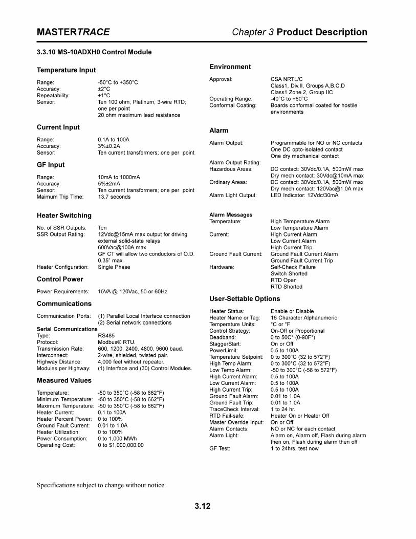
3.3.10 MS-10ADXH0 Control Module
Temperature Input
Range: -50°C to +350°CAccuracy: ±2°CRepeatability: ±1°CSensor: Ten 100 ohm, Platinum, 3-wire RTD;
one per point20 ohm maximum lead resistance
Current Input
Range: 0.1A to 100AAccuracy: 3%±0.2ASensor: Ten current transformers; one per point
GF Input
Range: 10mA to 1000mAAccuracy: 5%±2mASensor: Ten current transformers; one per pointMaimum Trip Time: 13.7 seconds
Heater Switching
No. of SSR Outputs: TenSSR Output Rating: 12Vdc@15mA max output for driving
external solid-state relays600Vac@100A max.GF CT will allow two conductors of O.D.0.35� max.
Heater Configuration: Single Phase
Control Power
Power Requirements: 15VA @ 120Vac, 50 or 60Hz
Communications
Communication Ports: (1) Parallel Local Interface connection(2) Serial network connections
Serial CommunicationsType: RS485Protocol: Modbus® RTU.Transmission Rate: 600, 1200, 2400, 4800, 9600 baud.Interconnect: 2-wire, shielded, twisted pair.Highway Distance: 4,000 feet without repeater.Modules per Highway: (1) Interface and (30) Control Modules.
Measured Values
Temperature: -50 to 350°C (-58 to 662°F)Minimum Temperature: -50 to 350°C (-58 to 662°F)Maximum Temperature: -50 to 350°C (-58 to 662°F)Heater Current: 0.1 to 100AHeater Percent Power: 0 to 100%Ground Fault Current: 0.01 to 1.0AHeater Utilization: 0 to 100%Power Consumption: 0 to 1,000 MWhOperating Cost: 0 to $1,000,000.00
Environment
Approval: CSA NRTL/CClass1, Div.II, Groups A,B,C,DClass1 Zone 2, Group IIC
Operating Range: -40°C to +60°CConformal Coating: Boards conformal coated for hostile
environments
Alarm
Alarm Output: Programmable for NO or NC contactsOne DC opto-isolated contactOne dry mechanical contact
Alarm Output Rating:Hazardous Areas: DC contact: 30Vdc/0.1A, 500mW max
Dry mech contact: 30Vdc@10mA maxOrdinary Areas: DC contact: 30Vdc/0.1A, 500mW max
Dry mech contact: [email protected] maxAlarm Light Output: LED Indicator: 12Vdc/30mA
Alarm MessagesTemperature: High Temperature Alarm
Low Temperature AlarmCurrent: High Current Alarm
Low Current AlarmHigh Current Trip
Ground Fault Current: Ground Fault Current AlarmGround Fault Current Trip
Hardware: Self-Check FailureSwitch ShortedRTD OpenRTD Shorted
User-Settable Options
Heater Status: Enable or DisableHeater Name or Tag: 16 Character AlphanumericTemperature Units: °C or °FControl Strategy: On-Off or ProportionalDeadband: 0 to 50C° (0-90F°)StaggerStart: On or OffPowerLimit: 0.5 to 100ATemperature Setpoint: 0 to 300°C (32 to 572°F)High Temp Alarm: 0 to 300°C (32 to 572°F)Low Temp Alarm: -50 to 300°C (-58 to 572°F)High Current Alarm: 0.5 to 100ALow Current Alarm: 0.5 to 100AHigh Current Trip: 0.5 to 100AGround Fault Alarm: 0.01 to 1.0AGround Fault Trip: 0.01 to 1.0ATraceCheck Interval: 1 to 24 hr.RTD Fail-safe: Heater On or Heater OffMaster Override Input: On or OffAlarm Contacts: NO or NC for each contactAlarm Light: Alarm on, Alarm off, Flash during alarm
then on, Flash during alarm then offGF Test: 1 to 24hrs, test now
Specifications subject to change without notice.

3.13
MASTERTRACE Chapter 3 Product Description
3.3.11 ML100 Dedicated Interface Module
Control Power
Power Requirements: From Control Module ML100 Interfaceconnector: +5Vdc/0.1A, +8Vdc/0.4A,-6.5Vdc/1mA
Communications
Port: 1 Dedicated parallel connectionInterconnect: 26-pin IDC ribbon cableCable Length: 3 feet maximum
Environment
Approval: CSA NRTL/CClass 1, Div.II, Groups A,B,C,DClass 1, Zone-2, Groups IIC
Operating Range: -40°C to +60°CConformal Coating: Boards conformal coated for hostile
environments
User Interface
Display: 20-character x 2-line VFD Alpha-numeric display
Keypad: 9 tactile keys, polyester faceplate- Setpoint, measured, status- Message Up, Message Down- Value Up, Value Down- Reset- Store
Contrast: Adjustable by potentiometerPanel Indicators: Power on
Current heater display onSerial communication activeSystem alarmProcess alarm
Bezel
Material: 304 Stainless steelMounting: For mounting on NEMA-12 or NEMA-4
enclosure door. Includes gasketing.Optional: 304 Stainless steel shroud with plexi-
glass hinged cover to protect keypadfrom physical damage.
Specifications subject to change without notice.
3.3.12 MR100 Group Interface Module
Control Power
Power Requirements: 12VA @ 120Vac, 50 or 60Hz
Communications
Ports: 1 Serial network connectionsType: RS485Protocol: Modbus® RTU.Transmission Rate: 600, 1200, 2400, 4800, 9600 baud.Interconnect: 2-wire, shielded, twisted pair.Highway Distance: 4,000 feet without repeater.Modules per Highway: (1) MR100 and (30) Control Modules.
Environment
Approval: CSA NRTL/CClass1, Div.II, Groups A,B,C,DClass1 Zone 2, Group IIC
Operating Range: -40°C to +60°CConformal Coating: Boards conformal coated for hostile
environments
Alarm
Alarm Output: Programmable for NO or NC contactsOne DC opto-isolated contactOne dry mechanical contact
Alarm Output Rating:Hazardous Areas: DC contact: 30Vdc/0.1A, 500mW max
Dry mech contact: 30Vdc@10mA maxOrdinary Areas: DC contact: 30Vdc/0.1A, 500mW max
Dry mech contact: [email protected] maxAlarm Light Output: LED Indicator: 12Vdc/30mAAlarm Messages: Refer to Control Module Specifications
User Interface
Display: 20-character x 2-line VFD Alpha-numeric display
Keypad: 9 tactile keys, polyester faceplate- Setpoint, measured, status- Message Up, Message Down- Value Up, Value Down- Reset- Store
Contrast: Adjustable by potentiometerPanel Indicators: Power on
Current heater display onSerial communication activeSystem alarmProcess alarm
Bezel
Material: 304 Stainless steelMounting: For mounting on NEMA-4/4X
enclosure door. Includes gasketing.Optional: 304 Stainless steel shroud with plexi-
glass hinged cover to protect keypadfrom physical damage.
3.14
MASTERTRACE Chapter 3 Product Description
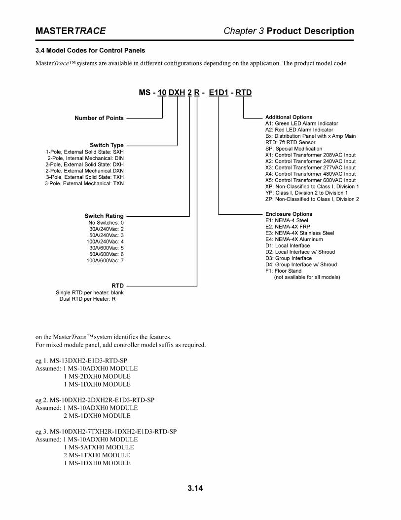
3.4 Model Codes for Control Panels
MasterTrace� systems are available in different configurations depending on the application. The product model code
on the MasterTrace� system identifies the features.For mixed module panel, add controller model suffix as required.
eg 1. MS-13DXH2-E1D3-RTD-SPAssumed: 1 MS-10ADXH0 MODULE
1 MS-2DXH0 MODULE1 MS-1DXH0 MODULE
eg 2. MS-10DXH2-2DXH2R-E1D3-RTD-SPAssumed: 1 MS-10ADXH0 MODULE
2 MS-1DXH0 MODULE
eg 3. MS-10DXH2-7TXH2R-1DXH2-E1D3-RTD-SPAssumed: 1 MS-10ADXH0 MODULE
1 MS-5ATXH0 MODULE2 MS-1TXH0 MODULE1 MS-1DXH0 MODULE
MS - 10 DXH 2 R - E1D1 - RTD
Number of Points
Enclosure OptionsE1: NEMA-4 SteelE2: NEMA-4X FRPE3: NEMA-4X Stainless SteelE4: NEMA-4X AluminumD1: Local InterfaceD2: Local Interface w/ ShroudD3: Group InterfaceD4: Group Interface w/ ShroudF1: Floor Stand
(not available for all models)
Switch Type1-Pole, External Solid State: SXH2-Pole, Internal Mechanical: DIN
2-Pole, External Solid State: DXH2-Pole, External Mechanical:DXN3-Pole, External Solid State: TXH3-Pole, External Mechanical: TXN
Switch RatingNo Switches: 030A/240Vac: 250A/240Vac: 3
100A/240Vac: 430A/600Vac: 550A/600Vac: 6
100A/600Vac: 7
Additional OptionsA1: Green LED Alarm IndicatorA2: Red LED Alarm IndicatorBx: Distribution Panel with x Amp MainRTD: 7ft RTD SensorSP: Special ModificationX1: Control Transformer 208VAC InputX2: Control Transformer 240VAC InputX3: Control Transformer 277VAC InputX4: Control Transformer 480VAC InputX5: Control Transformer 600VAC InputXP: Non-Classified to Class I, Division 1YP: Class I, Division 2 to Division 1ZP: Non-Classified to Class I, Division 2
RTDSingle RTD per heater: blank
Dual RTD per Heater: R
4.1
MASTERTRACE Chapter 4 Installation
4 Installation
4.1 Control Panel Mounting
Mount the control panel at a convenient location, gener-ally with the Interface Module at eye level. Placing theInterface Module in direct sunlight may make reading thedisplay difficult.Cut holes and mount hubs at suitable locations in theenclosure as required. It is recommended that powerwires are run in separate conduits from RTD and RS-485signal wires.
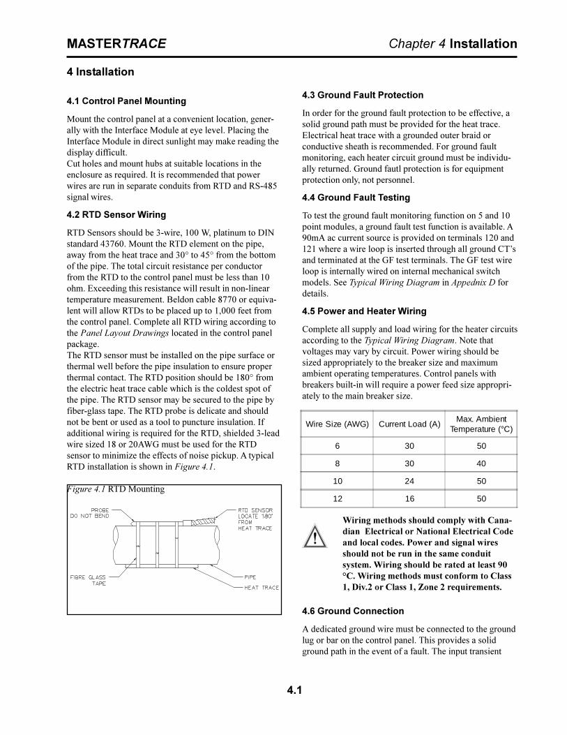
4.2 RTD Sensor Wiring
RTD Sensors should be 3-wire, 100 W, platinum to DINstandard 43760. Mount the RTD element on the pipe,away from the heat trace and 30° to 45° from the bottomof the pipe. The total circuit resistance per conductorfrom the RTD to the control panel must be less than 10ohm. Exceeding this resistance will result in non-lineartemperature measurement. Beldon cable 8770 or equiva-lent will allow RTDs to be placed up to 1,000 feet fromthe control panel. Complete all RTD wiring according tothe Panel Layout Drawings located in the control panelpackage.The RTD sensor must be installed on the pipe surface orthermal well before the pipe insulation to ensure properthermal contact. The RTD position should be 180° fromthe electric heat trace cable which is the coldest spot ofthe pipe. The RTD sensor may be secured to the pipe byfiber-glass tape. The RTD probe is delicate and shouldnot be bent or used as a tool to puncture insulation. Ifadditional wiring is required for the RTD, shielded 3-leadwire sized 18 or 20AWG must be used for the RTDsensor to minimize the effects of noise pickup. A typicalRTD installation is shown in Figure 4.1.
Figure 4.1 RTD Mounting
4.3 Ground Fault Protection
In order for the ground fault protection to be effective, asolid ground path must be provided for the heat trace.Electrical heat trace with a grounded outer braid orconductive sheath is recommended. For ground faultmonitoring, each heater circuit ground must be individu-ally returned. Ground fautl protection is for equipmentprotection only, not personnel.
4.4 Ground Fault Testing
To test the ground fault monitoring function on 5 and 10point modules, a ground fault test function is available. A90mA ac current source is provided on terminals 120 and121 where a wire loop is inserted through all ground CT�sand terminated at the GF test terminals. The GF test wireloop is internally wired on internal mechanical switchmodels. See Typical Wiring Diagram in Appednix D fordetails.
4.5 Power and Heater Wiring
Complete all supply and load wiring for the heater circuitsaccording to the Typical Wiring Diagram. Note thatvoltages may vary by circuit. Power wiring should besized appropriately to the breaker size and maximumambient operating temperatures. Control panels withbreakers built-in will require a power feed size appropri-ately to the main breaker size.
Wiring methods should comply with Cana-dian Electrical or National Electrical Codeand local codes. Power and signal wiresshould not be run in the same conduitsystem. Wiring should be rated at least 90°C. Wiring methods must conform to Class1, Div.2 or Class 1, Zone 2 requirements.
4.6 Ground Connection
A dedicated ground wire must be connected to the groundlug or bar on the control panel. This provides a solidground path in the event of a fault. The input transient
Wire Size (AWG) Current Load (A)Max. Ambient
Temperature (°C)
6 30 50
8 30 40
10 24 50
12 16 50

4.2
MASTERTRACE Chapter 4 Installation
protectors on the modules can not provide the necessaryprotection without a solid ground.
4.7 Safety Ground
Each of the ten RTD inputs are protected by a transientsuppressor network which acts as a barrier againsttransient energy pick-up by the RTD probe. In order forthis protection to work effectively, terminals 122 and 123must be terminated to a solid ground separate from theenclosure chassis ground. On panels pre-wired at thefactory, transient ground is tied to earth ground so that itis not left open. It is recommended that transient groundbe disconnected from enclosure ground and moved to aseparate ground.Note: The transient suppressor network is not an intrinsi-cally safe barrier and is only available on 5 and 10 pointmodels.
4.8 Control Power Wiring
The control panel requires control power supplied from adedicated circuit breaker. The supply voltage for controlpower to the MasterTrace modules is 120VAC. If thesupply voltage is incorrect, the modules may be damaged.Control power must be protected by a circuit breaker nolarger than 15A. If the control panel includes a breakerpanel, control power connection to a branch breaker willbe already done at the factory. Recommended wire sizefor control power wiring is 14 AWG at maximum ambienttemperature of 40°C and 12 AWG t maximum ambienttemperature of 50°C.
Wiring methods should comply with Cana-dian Electrical or National Electrical Codeand local codes. Power and signal wiresshould not be run in the same conduitsystem. Wiring should be rated at least 90°C. Wiring methods must conform to Class1, Div.2 or Class 1, Zone 2 requirements.
4.9 Alarm Wiring
MasterTrace controllers have two alarm contacts and oneactive alarm output for driving a LED alarm indicator.Both the alarm contacts are software configurable fornormally open or closed. The alarm LED output issoftware configurable for alarm on, alarm off or flashduring alarm. Refer to typical wiring diagrams in Appen-dix D for alarm output terminals.The mechanical alarm output is rated 30Vdc, 0.1A inhazardous locations and 120Vac/1A in ordinary areas.The DC alarm output is an opto-isolated transition output
4.9 Commissioning
Commissioning the MasterTrace� Control Panel requiresan understanding of its functions including how to displaymeasured values and, if necessary, to change setpoints orconfiguration. Read Chapter 5: Operation and Chapter 6:Programming & Setup before proceeding if you are notfamiliar with the MasterTrace� operation.Once the wiring is complete and in accordance with theTypical Wiring Diagram in Appendix D, close the circuitbreaker to provide control power to the panel.On power-up, the Interface Module displays this sequenceof messages:
MASTERTRACE HEATTRACING CONTROL
NEXTRON CORP(403)735-9555
FIRMWARE VERSION:REV. D1-02-01
MANUAL VERSION:1501-0006_1
SELF TESTPASSED
Refer to Appendix C: Summary of Alarms and Causes, ifthe Self Test Failure alarm light turns on or the InterfaceModule displays this message:
SELF TESTFAILURE ALARM
rated 30Vdc/100mA, 500mW max.The alarm LED output is rated 12Vdc, 30mA. It can beused to drive a 12Vdc LED indicator. Alarm outputs aredesigned for interface to annunciator, panels, PLC orDCS.

4.3
MASTERTRACE Chapter 4 Installation
4.9.1 Enter Program Changes: Refer to the ProgrammingSheet for Control Panel & Modules (Rev. D1).Refer toFigure 4.1 for Sample Programming Worksheet. Ignoringthe alarm messages and lights, enter all required usersetup changes. The Program Enable dip switch/terminalson the Interface Module must be set to ENABLE to allowprogramming. Refer to Figure5.7 for the ML100 Dedi-cated Interface Module or Figure 5.9 for the MR100Group Interface Module. It is recommended that thisdip switch be set to DISABLE or the terminals bejumpered to prevent unauthorized entry of programchanges.
4.9.2 Turn On Heater Power: Close the circuit breakersfor all heat trace circuits controlled by the MasterTrace�control panel.
4.9.3 Respond to Alarm Conditions: Examine each alarmcondition and correct problems as required. High Currentand Low Temperature alarms should be ignored duringstart-up and until normal operating levels have beenreached. Refer to Appendix C: Summary of Alarms andCauses for information on potential causes of alarms.
4.9.4 Check Actual Readings: Once the system hasreached normal operating temperatures, check theindividual temperature, current and ground fault currentreadings against expected values for each circuit. This canindicate wiring or design errors.
4.9.5 Check the RTD Wiring: Locate and open thejunction box or head of the selected RTD. Either discon-nect the RTD or short the wires. The RTD Short or RTDOpen alarm will be displayed on the Interface Moduleshowing the Heater Name. Confirm that the displayedheater matches the heater of the selected RTD.
Warning - Explosion Hazard - Substitutionof components may impair suitablility forClass 1, Division 2 or Class 1, Zone 2.
Warning - Explosion Hazard - Do notdisconnect equipment unless power hasbeen switched off or the area is known to benon-hazardous.
Warning - The ground fault trip function isintended for equipment protection only andshould not be used in place of ground faultprotection for personnel protection wherethis is required.
There are no consumable components contained in any ofthe models covered in this manual.There is no cleaning requirements for any of the modelscovered in this manual.
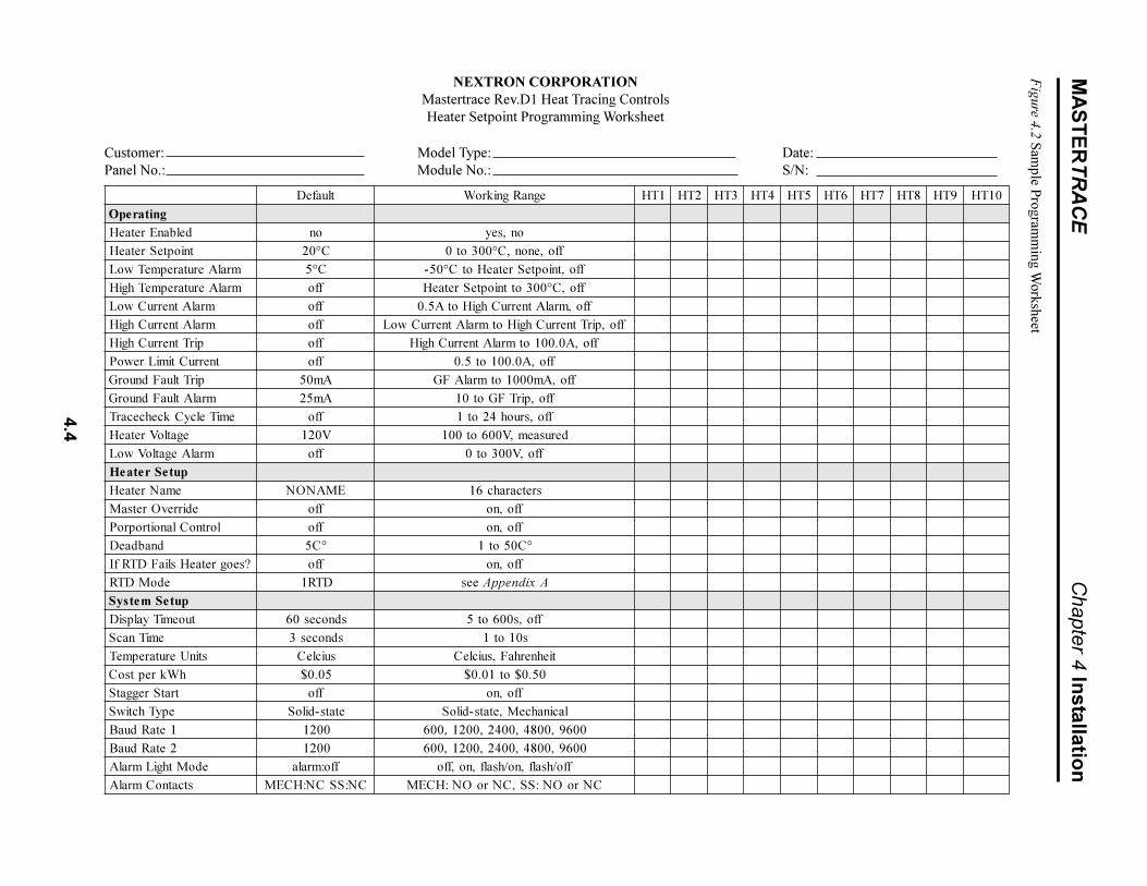
4.4
MA
ST
ER
TR
AC
EC
hapter 4 Installatio
n
tluafeD egnaRgnikroW 1TH 2TH 3TH 4TH 5TH 6TH 7TH 8TH 9TH 01TH
gnitarepOdelbanEretaeH on on,seytniopteSretaeH C°02 ffo,enon,C°003ot0
mralAerutarepmeTwoL C°5 ffo,tniopteSretaeHotC°05-mralAerutarepmeThgiH ffo ffo,C°003ottniopteSretaeH
mralAtnerruCwoL ffo ffo,mralAtnerruChgiHotA5.0mralAtnerruChgiH ffo ffo,pirTtnerruChgiHotmralAtnerruCwoL
pirTtnerruChgiH ffo ffo,A0.001otmralAtnerruChgiHtnerruCtimiLrewoP ffo ffo,A0.001ot5.0
pirTtluaFdnuorG Am05 ffo,Am0001otmralAFGmralAtluaFdnuorG Am52 ffo,pirTFGot01
emiTelcyCkcehcecarT ffo ffo,sruoh42ot1egatloVretaeH V021 derusaem,V006ot001
mralAegatloVwoL ffo ffo,V003ot0puteSretaeH
emaNretaeH EMANON sretcarahc61edirrevOretsaM ffo ffo,no
lortnoClanoitroproP ffo ffo,nodnabdaeD °C5 °C05ot1
?seogretaeHsliaFDTRfI ffo ffo,noedoMDTR DTR1 ees AxidneppA
puteSmetsyStuoemiTyalpsiD sdnoces06 ffo,s006ot5
emiTnacS sdnoces3 s01ot1stinUerutarepmeT suicleC tiehnerhaF,suicleC
hWkreptsoC 50.0$ 05.0$ot10.0$tratSreggatS ffo ffo,no
epyThctiwS etats-diloS lacinahceM,etats-diloS1etaRduaB 0021 0069,0084,0042,0021,0062etaRduaB 0021 0069,0084,0042,0021,006
edoMthgiLmralA ffo:mrala ffo/hsalf,no/hsalf,no,ffostcatnoCmralA CN:SSCN:HCEM CNroON:SS,CNroON:HCEM
NEXTRON CORPORATIONMastertrace Rev.D1 Heat Tracing ControlsHeater Setpoint Programming Worksheet
Customer: Model Type: Date:Panel No.: Module No.: S/N:
Figure 4.2 Sam
ple Program
ming W
orksheet

5.1
MASTERTRACE Chapter 5 Operation
5 Operation
This section provides information on how to operate theMasterTrace� modules. Refer to the module nameplate(s) and Chapter 3.4, Model Codes, if you are unsureof your product and its specific features.
5.1 Control Modules
Refer to the following Figures for the appropriate ControlModule(s).� Figure 5.1: MS-1DIN2 & MS-2DIN2
� Figure5.2: MS-1TXH0
� Figure 5.3: MS-1DXH0 & MS-2DXH0
� Figure5.4: MS-5ADIN2 & MS-10ADIN2
� Figure 5.5: MS-5ADXH0, MS-5ATXH0 & MS-10ADXH0
5.1.1 Status Lights:
� L1 Power: Light is on when control power is present.
� L2 Heater: Each heater circuit has a light which is onwhen the heater relay or contactor is closed.
� L3 Alarm: Light is on if there are one or more alarmson any circuits of the Control Module.
� L4 Address: Light is on when Control Module is inAddress Enable Mode. Light must be on to allow theModule Number to be changed from a master on thedata highway.
� L5 Transmit: Each serial port has a light which flasheswhile the Control Module is transmitting informationto the data highway.
� L6 Receive: Each serial port has a light which flasheswhile the Control Module is receiving informationfrom the data highway.
� L7 Override: Light is on when the Override Inputterminals are shorted. All heaters which are pro-grammed with Master Override set to ON should be onwhen light is on.
5.1.2 Switches & Jumpers:
� S1 Address Mode: When the switch is set toDISABLE, the Module Number cannot be changedfrom a master on the data highway. When set toENABLE, the Module Number can be changed for thenext ten minutes from a master on the data highway.During this time the ADDRESS light is on.
� S2 RS485-120: When the jumper is set to IN, theRS-485 line is terminated by a 120 ohm resistor. Onlythe last Control Module on the data highway should beset to IN.
5.1.3 Terminals: Refer to Typical Wiring Diagrams for
power, heater and RTD field connections.Note: Not all models are equipped with the following.� T1 Alarm Contacts: Alarm contact type is the same for
all models. In hazardous areas the opto-isolated dcoutput is rated 30 Vdc @ 0.1 A (terminals 4 and 5) andthe dry mechanical output is rated 30Vdc@10mA(terminals 6 and 7). In ordinary areas the opto-isolateddc output is rated the same as hazardous but the drymechanical output is rated 120 Vac@1A. Contacts areconfigurable for normally open or closed.
� T2 Alarm Light Output: The output is configurable fornormally open, closed or flash. Output is rated 12 Vdc@ 30 mA for an LED type lamp (MS-1 & MS-2terminals 16+ and 17-, MS-5A and MS-10A terminals13+ and 14-).
� T3 Master Override Input: Only those heaters whichare programmed with Master Override set to ON areaffected by the Master Override Input. When theterminals are open, all Master Override Enabledheaters are forced off. When the terminals are closed,all Master Override Enabled heaters are controlled bytheir individual RTDs unless their Heater Setpoint isset to OFF. In this case, the heater is turned on. Thelogic of this input allows either ambient temperatureoverride or load shedding on all or selected heaters.(MS-1 & MS-2 terminals 26+ and 27-, MS-5A andMS-10A terminals 11+ and 12-).
� T4 RTD Input: 3 wire RTD input. Ground terminalconnects to shield or case. Lead resistance compen-sated. (MS-1 & MS-2 terminals 8-15, MS-5A and MS-10A terminals 60-99).
� T5 Control Power Input:120Vac input, 2A fused(terminals 2 and 3), earth ground (terminal 1).
� T6 CT�s: Heater Current and Ground Fault monitoringtransformers (MS-1 & MS-2 terminals 28-35, MS-5Aand MS-10A terminals 20-59). Solid-state models only.
� T7 SSR�s: 12Vdc, 15mA max for driving digital inputof solid state relays (MS-1 & MS-2 terminals 40-43,
� MS-5A and MS-10A terminals 100-119). Solid-statemodels only.
� T8 Voltage: Connect to heater input for voltagemonitoring. 300Vac max. (MS-1 & MS-2 terminals 36-39). One and two-point single-phase solid-state modelsonly.
� T9 Safety Ground: Terminate to solid groundseparate from panel ground for transient protectioncircuit on RTD inputs. (MS-5A and MS-10A terminals122 and 123). Five and ten-point models only.

5.2
MASTERTRACE Chapter 5 Operation
Figure 5.1 MS-1DIN2 & MS-2DIN2 Control Modules
� T10 GF Test: Wire loop is passed through GF CT�sand terminated at the GF test terminals. An ac testcurrent is applied through wire loop during GF testing.(MS-5A and MS-10A terminals 120 and 121). Five andten-point models only.
� T11 Address Enable Open: When the terminals areshorted, the Module Number cannot be changedfrom a master on the data highway. (MS-1 & MS-2terminals 24 and 25). One and two-point models only.
� T12 Heater Power Input: 280Vac max input voltage.(MS-1 & MS-2 terminals 28, 29, 32 and 33, MS-5Aand MS-10A terminals 20-39). Mechanical modelsonly.
� T13 Heater Power Output: 280Vac/30A max continu-ous (MS-1A & MS-2A terminals 30, 31, 34 and 35,MS-5A and MS-10A terminals 40-59). Mechanicalmodels only.
5.1.4.Communications Ports:
� C1 ML100 Interface: Standard connection to aDedicated Interface Module via a ribbon cable.Maximum cable length is five feet.
� C2 Serial Port 1: Standard connection to an RS-485data highway via a 2-conductor, shielded, twisted paircable. Maximum Cable length with 30 Control Mod-ules without repeater is 4,000 feet. (MS-1 & MS-2terminals 18+, 19-, 20 SHD, MS-5A and MS-10Aterminals 8+, 9-, 10 SHD)
� C3 Serial Port 2: Standard connection to a secondRS-485 data highway via a 2-conductor, shielded,twisted pair cable. Maximum Cable length with 30Control Modules without repeater is 4,000 feet. (MS-1& MS-2 terminals 21+, 22-, 23 SHD, MS-5A and MS-10A terminals 17+, 18-, 19 SHD)
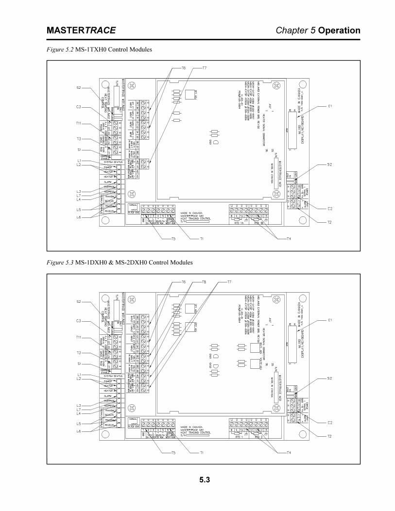
5.3
MASTERTRACE Chapter 5 Operation
Figure 5.3 MS-1DXH0 & MS-2DXH0 Control Modules
Figure 5.2 MS-1TXH0 Control Modules
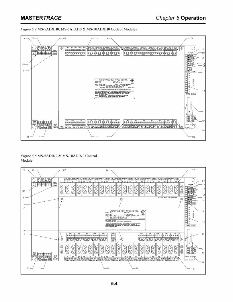
5.4
MASTERTRACE Chapter 5 Operation
Figure 5.5 MS-5ADIN2 & MS-10ADIN2 ControlModule
Figure 5.4 MS-5ADXH0, MS-5ATXH0 & MS-10ADXH0 Control Modules

5.5
MASTERTRACE Chapter 5 Operation
5.2 Interface Modules
The ML100 Dedicated Interface Module is capable ofprogramming and monitoring one Control Module such asthe MS-10A. It is a �Dedicated� interface because itconnects to only one Control Module. It is designed to bedoor-mounted in a NEMA-4 enclosure in an industrialenvironment. Operator interface is through the StatusIndicators, LCD Display and the Keypad. Refer to Figure5-6 and Figure 5-7.The MR100 Group Interface Module is capable ofprogramming and monitoring from one to thirty ControlModules. It is a �Group� interface because it connects,via a serial cable to several Control Modules. It isdesigned to be door-mounted in a NEMA-4 enclosure inan industrial environment. Operator interface is throughthe Status Indicators, LCD Display and the Keypad. Referto Figure 5-6 and Figure 5-8.
5.2.1 Status Lights Located on Circuit Board :
� L8 Transmit: LED flashes when the InterfaceModule is transmitting information to the datahighway. MR100 only.
� L9 Receive: LED flashes when the Interface Module isreceiving information from the data highway. MR100only.
5.2.2 Switches and Jumpers:
� S3 Program Enable: When the Program Enable dipswitch is set to DISABLE, programming is disabledand setpoints and configuration cannot be changed.Otherwise, programming is allowed.
5.2.3 Terminals: Refer to the Typical Wiring Diagramsfor power field connections.
� T14 Alarm Contacts: In hazardous areas the dc outputis rated 30 Vdc @ 0.1 A (terminals 906 and 907) andthe dry mechanical output is rated 30Vdc@10mA(terminals 904 and 905). In ordinary areas the dcoutput is rated the same as hazardous but the drymechanical output is rated 120 Vac@1A. Contacts areconfigurable for normally open or closed. MR100 only.
� T15 Alarm Light Output: The output is configurableor normally open, closed or flash. Output is rated12 Vdc @ 30 mA for an LED type lamp (terminals909+ and 908-). MR100 only.
� T16 Control Power Input:120Vac input (terminals 902and 903), earth ground (terminal 901). MR100 only.
� T17 Program Enable: When shorted, programming isdisabled; setpoints and configuration cannot bechanged. When open, programming is allowed.(MR100 terminals 913 and 914)
5.2.4 Communications Port:
� C4 Parallel Port: Standard connection to a singleControl Module via a ribbon cable. Maximum cablelength is five feet. ML100 only.
� C5 Serial Port : Standard connection to an RS-485data highway via a 2-conductor, shielded, twisted paircable. Maximum Cable length with 30 Control Mod-ules without repeater is 4,000 feet. (terminals 912+,911-, 910 SHD). MR100 only.
5.2.5 Trim Potentiometers:
� P1 LCD display: Adjusts the contrast according to theviewing angle.
5.2.6 Status Lights Located on Faceplate :
� L10 Power: The green Power light should be on at alltimes indicating that control power is applied to theInterface Module. If the light is off either there is novoltage across terminals 902 and 903 or the InterfaceModule has a malfunction and requires servicing.
� L11 Heater: The green Heater light is on if the se-lected heater is energized.
� L12 Communicate: Random flashing of the greenCommunicate light indicates that serial communica-tions are active on the Control Module to which it isconnected.
� L13 System Fail: The red System Fail light should beoff, indicating that the system check was successful. Onthe Dedicated Interface Module, if the light is on, theControl Module has failed its self-test and requiresservicing. On the Group Interface Module, if the lightis on, the Group Interface Module has failed its self-test and requires servicing.
� L14 Alarm: The red alarm light is off when there areno alarms. The light will flash if any alarm conditionsare present. Press [STATUS] to view alarms.
5.2.7 Alphanumeric Display:
� D1 Display: Two lines with sixteen alphanumericcharacters per line. It is backlit for viewing in low-lightconditions.
5.2.8 Keypad:
� K1 Interface Module Keypad: Consists of nine keyswhich, when used in connection with the AlphanumericDisplay, allow complete control of programming andmonitoring of any Control Module connected to theInterface Module.
The [SETPOINT] key provides entry to the SetpointMenu which allows the user to program and test allconnected Control Modules. The Setpoint Menu is arranged in four columns. Quickly

5.6
MASTERTRACE Chapter 5 Operation
pressing [SETPOINT] twice accesses the top of thesecond column; pressing three times accesses the top ofthe third column, and so on.The [MEASURED] key provides entry to the MeasuredValues Menu which allows the user to display the meas-ured values for all connected Control Modules. TheMeasured Values Menu is arranged in three columns.Quickly pressing [MEASURED] twice accesses the top ofthe second column; pressing three times accesses the topof the third column.The [STATUS] key provides immediate access to theSystem Status Menu which displays the alarm status forall connected Control Modules and allows access toindividual alarm details.The [MESSAGE ñ] key allows the user to move upthrough the selected menu.The [MESSAGE ò] key allows the user to move downthrough the selected menu.The [VALUE ñ] key allows the user to increase the valueof the displayed selected item.The [VALUE ò] key allows the user to decrease the valueof the displayed selected item.The [STORE] key allows the user to save the changedvalue of the selected item.The [RESET] key allows the user to clear alarms that areno longer active.5.2.9 Heater Numbering: Each heater is identified by a
number of the form �M-H�, where �M� is the ModuleNumber and �H� is the local heater number. Ten-pointControl Modules have local heater numbers from �1�through �10�. Each Control Module on the same datahighway must have a unique Module Number.
5.2.10 Example: Display the Heater Control Temperaturefor Heater 3-2Press [MEASURED] to enter the Measured Values Menuas shown:
MEASUREDOPERATING VALUES
SELECT HT: 3-2?NONAME &
Press [VALUE ñ] or [VALUE ñ] to select Heater 3-2.Press [STORE].Press [MESSAGE ò] until the desired value is displayedas shown:
HEATER CONTROLTEMP: 55°C &
Figure 5.6 ML100 & MR100 Interface Modules, Front View

5.7
MASTERTRACE Chapter 5 Operation
Figure 5.7 ML100 Dedicated Interface Modules, Rear View
Figure 5.8 MR100 Group Interface Modules, Rear View
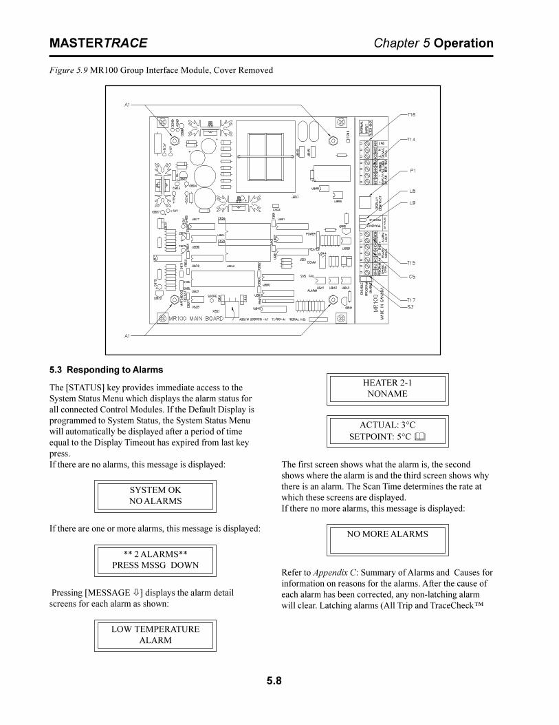
5.8
MASTERTRACE Chapter 5 Operation
Figure 5.9 MR100 Group Interface Module, Cover Removed
5.3 Responding to Alarms
The [STATUS] key provides immediate access to theSystem Status Menu which displays the alarm status forall connected Control Modules. If the Default Display isprogrammed to System Status, the System Status Menuwill automatically be displayed after a period of timeequal to the Display Timeout has expired from last keypress.If there are no alarms, this message is displayed:
SYSTEM OKNO ALARMS
If there are one or more alarms, this message is displayed:
** 2 ALARMS**PRESS MSSG DOWN
Pressing [MESSAGE ò] displays the alarm detailscreens for each alarm as shown:
LOW TEMPERATUREALARM
HEATER 2-1NONAME
ACTUAL: 3°CSETPOINT: 5°C &
The first screen shows what the alarm is, the secondshows where the alarm is and the third screen shows whythere is an alarm. The Scan Time determines the rate atwhich these screens are displayed.If there no more alarms, this message is displayed:
NO MORE ALARMS
Refer to Appendix C: Summary of Alarms and Causes forinformation on reasons for the alarms. After the cause ofeach alarm has been corrected, any non-latching alarmwill clear. Latching alarms (All Trip and TraceCheck�

5.9
MASTERTRACE Chapter 5 Operation
SETPOINTS:OPERATING VALUES
[MESSAGEô]
SELECT HT:1-1?NONAME &
[MESSAGEô]
HEATER ENABLED?yes ?
[MESSAGEô]
HEATER SETPOINT:5°C ?
[MESSAGEô]
LOW TEMPERATUREALARM: 2°C ?
[MESSAGEô]
HIGH TEMPERATUREALARM: off ?
[MESSAGEô]
LOW CURRENTALARM: off ?
[MESSAGEô]
HIGH CURRENTALARM: off ?
[MESSAGEô]
HIGH CURRENTTRIP: off ?
[MESSAGEô]
POWER LIMITCURRENT: off ?
[MESSAGEô]
GROUND FAULTALARM: 20mA ?
[MESSAGEô]
GROUND FAULTTRIP: 30mA ?
[MESSAGEô]
TRACECHECK CYCLE:TIME: off ?
[MESSAGEô]
HEATER VOLTAGE:120V ?
[MESSAGEô]
LOW VOLTAGE:ALARM: off ?
[MESSAGEô]go to 2
[SETPOINT]
ò 1
[SETPOINT]
ò
SETPOINTS:HEATER SETUP
[MESSAGEô]
SELECT HT: 1-1?NONAME &
[MESSAGEô]
HTR 1-1 NAME:NONAME ?
[MESSAGEô]
MASTER OVERRIDE:off ?
[MESSAGEô]
PROPORTIONALCONTROL: off ?
[MESSAGEô]
DEADBAND2 C° ?
[MESSAGEô]
IF RTD FAILSHEATER GOES: off ?
[MESSAGEô]
RTD MODE:2 RTD�s, lowest ?
[MESSAGEô]go to 3
[SETPOINT]
2 3 ò
DISPLAY MODE:normal user ?
[MESSAGEô]
DEFAULT DISPLAY:system status ?
[MESSAGEô]
DISPLAY TIMEOUT:60 seconds ?
[MESSAGEô]
SCAN TIME:3 seconds ?
[MESSAGEô]
TEMPERATUREUNITS: celcius ?
[MESSAGEô]
COST PER kWh:$0.05 ?
[MESSAGEô]
STAGGER START:off ?
[MESSAGEô]
SWITCH TYPE:none ?
[MESSAGEô]
SETPOINTS:SYSTEM SETUP
[MESSAGEô]
MODULE RANGE:1-30 ?
[MESSAGEô]
MODULE LIST:MOD: 1? SEL:yes?
[MESSAGEô]
[SETPOINT]ò 5
MANUAL SYSTEM:ALARM: disabled ?
[MESSAGEô]
GF TEST:test now ?
[MESSAGEô]go to 1
SETPOINTS:SETPOINTS TEST
[MESSAGEô]
MANUAL ALARM:disabled ?
[MESSAGEô]
MANUAL HEATER:disabled ?
[MESSAGEô]
BAUD RATE 2:1200 ?
[MESSAGEô]
ALARM LIGHT MODE:alarm: off ?
[MESSAGEô]go to 4
RESET CONTROLMODULE? no ?
[MESSAGEô]
SET MODULENUMBER: no ?
[MESSAGEô]
RESET MR100:no ?
[MESSAGEô]
FIRMWARE VERSION:D1-02-01
[MESSAGEô]
MANUAL VERSION:1501-0006_1
[MESSAGEô]
FOR ASSISTANCE:(403) 735-9555
[MESSAGEô]go to 5
4 ò
Restrictions1 1- & 2-point Modules2 5- & 10-point Modules3 Dual RTD Modules4 Solid-State Switch Modules5 MR100 Interface Module Advanced User Mode
4
1
3
4
5
5
5
5
4
READ MODULENUMBER: 1?
[MESSAGEô]
ALARM CONTACTS:MECH: NC? SS: NC?
[MESSAGEô]
5
5
ð ð ð
2
alarms) must be reset to clear the alarm. To reset the alarm, first
BAUD RATE 1:1200 ?
[MESSAGEô]
BAUD RATE MR100:1200 ?
[MESSAGEô]
5

5.10
MASTERTRACE Chapter 5 Operation
5.5 Setpoint Values Menu: Three-Phase Modules (1- and 5-point only)
SETPOINTS:OPERATING VALUES
[MESSAGEô]
SELECT HT:1-1?NONAME &
[MESSAGEô]
HEATER ENABLED?yes ?
[MESSAGEô]
HEATER SETPOINT:5°C ?
[MESSAGEô]
LOW TEMPERATUREALARM: 2°C ?
[MESSAGEô]
HIGH TEMPERATUREALARM: off ?
[MESSAGEô]
A: LOW CURRENTALARM: off ?
[MESSAGEô]
C: HIGH CURRENTALARM: off ?
[MESSAGEô]
[SETPOINT]
ò 1
[SETPOINT]
ò
SETPOINTS:HEATER SETUP
[MESSAGEô]
SELECT HT: 1-1?NONAME &
[MESSAGEô]
HTR 1-1 NAME:NONAME ?
[MESSAGEô]
MASTER OVERRIDE:off ?
[MESSAGEô]
PROPORTIONALCONTROL: off ?
[MESSAGEô]
DEADBAND2 C° ?
[MESSAGEô]
IF RTD FAILSHEATER GOES: off ?
[MESSAGEô]
RTD MODE:2 RTD�s, lowest ?
[MESSAGEô]go to 4
[SETPOINT]
3 4 ò
DISPLAY MODE:normal user ?
[MESSAGEô]
DEFAULT DISPLAY:system status ?
[MESSAGEô]
DISPLAY TIMEOUT:60 seconds ?
[MESSAGEô]
SCAN TIME:3 seconds ?
[MESSAGEô]
TEMPERATUREUNITS: celcius ?
[MESSAGEô]
COST PER kWh:$0.05 ?
[MESSAGEô]
STAGGER START:off ?
[MESSAGEô]
SWITCH TYPE:none ?
[MESSAGEô]
SETPOINTS:SYSTEM SETUP
[MESSAGEô]
MODULE RANGE:1-30 ?
[MESSAGEô]
MODULE LIST:MOD: 1? SEL:yes?
[MESSAGEô]
[SETPOINT]ò 6
MANUAL SYSTEM:ALARM: disabled ?
[MESSAGEô]
GF TEST:test now ?
[MESSAGEô]go to 1
SETPOINTS:SETPOINTS TEST
[MESSAGEô]
MANUAL ALARM:disabled ?
[MESSAGEô]
MANUAL HEATER:disabled ?
[MESSAGEô]
MR100 BAUD RATE:1200 ?
[MESSAGEô]
RESET CONTROLMODULE? no ?
[MESSAGEô]
RESET MR100:no ?
[MESSAGEô]
MANUAL VERSION:1501-0006_1
[MESSAGEô]
FOR ASSISTANCE:(403) 735-9555
[MESSAGEô]go to 6
5 ò
Restrictions1 5-point Modules2 MR100 Interface Module Advanced User Mode
2
2
2
2
2
READ MODULENUMBER: 1?
[MESSAGEô]
ALARM CONTACTS:MECH: NC? SS: NC?
[MESSAGEô]
2
2
ð ð ð
POWER LIMITCURRENT: off ?
[MESSAGEô]
GROUND FAULTALARM: 20mA ?
[MESSAGEô]
GROUND FAULTTRIP: 30mA ?
[MESSAGEô]
TRACECHECK CYCLE:TIME: off ?
[MESSAGEô]
HEATER VOLTAGE:120V ?
[MESSAGEô]go to 3
2 ò
B: HIGH CURRENTTRIP: off ?
[MESSAGEô]
A: HIGH CURRENTTRIP: off ?
[MESSAGEô]
B: HIGH CURRENTALARM: off ?
[MESSAGEô]
A: HIGH CURRENTALARM: off ?
[MESSAGEô]
C: LOW CURRENTALARM: off ?
[MESSAGEô]
B: LOW CURRENTALARM: off ?
[MESSAGEô]
C: HIGH CURRENTTRIP: off ?
[MESSAGEô]go to 2
1
FIRMWARE VERSION:D1-02-01
[MESSAGEô]
SET MODULENUMBER: no ?
[MESSAGEô]
ALARM LIGHT MODE:alarm: off ?
[MESSAGEô]go to 5
BAUD RATE 2:1200 ?
[MESSAGEô]
BAUD RATE 1:1200 ?
[MESSAGEô]

5.11
MASTERTRACE Chapter 5 Operation
5.6 Measured Values Menu: Single-Phase Modules
MEASUREDOPERATING VALUES
[MESSAGEô]
SELECT HT:1-1?NONAME &
[MESSAGEô]
HEATER IS ON&& NO ALARMS
[MESSAGEô]
HEATER CONTROLTEMP: 6°C &
[MESSAGEô]
RTD-A ACTUALTEMP: 6°C &
[MESSAGEô]
RTD-B ACTUALTEMP: 6°C &
[MESSAGEô]
HEATER AT 100% &POWER
[MESSAGEô]
HEATER CURRENT:4.6A &
[MESSAGEô]
HEATER VOLTAGE:120V &
[MESSAGEô]
GROUND FAULTCURRENT: 5mA &
[MESSAGEô]go to 2
[MEASURED]
ò 1
[MEASURED]
ò
MEASUREDSTATISTICS
[MESSAGEô]
SELECT HT: 1-1?NONAME &
[MESSAGEô]
MIN TEMPERATURE:3°C &
[MESSAGEô]
MAX TEMPERATURE:25°C &
[MESSAGEô]
MAX HEATERCURRENT: 4.7A &
[MESSAGEô]
MAX GROUND FAULTCURRENT: 6mA &
[MESSAGEô]go to 3
2 3 ò
ENERGY USED LASTDAY: 2.1 kWh &
[MESSAGEô]
TOTAL ENERGYUSED: 42.2 kWh &
[MESSAGEô]
ENERGY COSTLAST DAY: $1.70 &
[MESSAGEô]
TOTAL ENERGYCOST: $33.92 &
[MESSAGEô]
HEATER ON TIME:80 hrs &
[MESSAGEô]
HEATER IS ON & 17% OF THE TIME
[MESSAGEô]
TIME SINCE RESET48 hrs &
[MESSAGEô]
Restrictions1 1- & 2-point Modules2 Dual RTD Modules Advanced User Mode
1 RESET STATISTICS?no &
[MESSAGEô]go to 1
ð
2
2
TOTAL RUN TIME:20966 hrs &
[MESSAGEô]

5.12
MASTERTRACE Chapter 5 Operation
5.7 Measured Values Menu: Three-Phase Modules
MEASUREDOPERATING VALUES
[MESSAGEô]
SELECT HT:1-1?NONAME &
[MESSAGEô]
HEATER IS ON&& NO ALARMS
[MESSAGEô]
HEATER CONTROLTEMP: 6°C &
[MESSAGEô]
RTD-A ACTUALTEMP: 6°C &
[MESSAGEô]
RTD-B ACTUALTEMP: 6°C &
[MESSAGEô]
HEATER AT 100% &POWER
[MESSAGEô]
A:HEATER CURRENT:4.6A &
[MESSAGEô]
GROUND FAULTCURRENT: 5mA &
[MESSAGEô]go to 2
[MEASURED]
ò 1
[MEASURED]
ò
MEASUREDSTATISTICS
[MESSAGEô]
SELECT HT: 1-1?NONAME &
[MESSAGEô]
MIN TEMPERATURE:3°C &
[MESSAGEô]
MAX TEMPERATURE:25°C &
[MESSAGEô]
A:MAX HEATERCURRENT: 4.7A &
[MESSAGEô]
MAX GROUND FAULTCURRENT: 6mA &
[MESSAGEô]go to 3
2 3 ò
ENERGY USED LASTDAY: 2.1 kWh &
[MESSAGEô]
TOTAL ENERGYUSED: 42.2 kWh &
[MESSAGEô]
ENERGY COSTLAST DAY: $1.70 &
[MESSAGEô]
TOTAL ENERGYCOST: $33.92 &
[MESSAGEô]
HEATER ON TIME:80 hrs &
[MESSAGEô]
HEATER IS ON & 17% OF THE TIME
[MESSAGEô]
TIME SINCE RESET48 hrs &
[MESSAGEô]
Restrictions Advanced User Mode
RESET STATISTICS?no &
[MESSAGEô]go to 1
ð
B:HEATER CURRENT:4.6A &
[MESSAGEô]
C:HEATER CURRENT:4.6A &
[MESSAGEô]
B:MAX HEATERCURRENT: 4.7A &
[MESSAGEô]
C:MAX HEATERCURRENT: 4.7A &
[MESSAGEô]
TOTAL RUN TIME:20966 hrs &
[MESSAGEô]

6.1
MASTERTRACE Chapter 6 Programming & Setup
6 Programming & Setup
6.1 Getting Started
Refer to the Programming Sheet for Control Panel orModules (Rev. D1) provided with the control panel or seeFigure 4.1 Sample Programming Worksheet. It shows theoptions available for your Control Modules and thevalues entered at the factory. Enter all changes to thefactory setup under �User Setup� prior to entering thechanges through the Interface Module. Increase the valuein the DISPLAY TIMEOUT function (msg. S3-06) so thatprogramming is not disrupted by the display switching tothe default. Chapters 5.4 and 5.5 show the SetpointValues Menu. A detailed description of messages is shownin Appendix A.
6.2 Program Enable
Each Interface Module is provided with a programminginterlock to prevent tampering with setpoints. Program-ming must be enabled for any values to be stored. Referto Chapter 2.3.1.
If the programming is disabled and [STORE] is pressed,this message is displayed:
NOT STOREDPROG DISABLED
6.3 Module List (MR100 Group Interface)
The MODULE LIST function (msg. S3-02) identifies allthe Control Modules that pole or communicate with theMR100 Interface Module. Each Control Module must be�Selected� for the MR100 to communicate with it. AnyControl Module not selected will be skipped by theSELECT HT functions (msg. M1-02, M2-02, S1-02 &S2-02). Note that a Control Module can still be fullyfunctional without communicating with an InterfaceModule.
6.4 Heater Enable
The HEATER ENABLED function (msg. S1-03) identi-fies which heater circuits to control and monitor. Anyheater circuit that is �Disabled� will not have any controlor monitoring and will be skipped by the SELECT HTfunction.
6.5 Example: Change the Setpoint for Heater 3-2 to 50 °C
Press [SETPOINT] to enter the Setpoint Menu. Thismessage is displayed:
SEPOINTS:OPERATING VALUES
SELECT HT: 3-2 ?NONAME &
Press [VALUE ñ] or [VALUE ò] to select heater 3-2.Press [STORE].
Press [MESSAGE ò] until the desired message isdisplayed as shown:
HEATER SETPOINT:55°C &
Press [VALUE ñ] or [VALUE ò]until desired tempera-ture is displayed (50 °C). Press [STORE].
If the value was successfully stored in the ControlModule, this message is displayed:
SETPOINT:STORED

7.1
MASTERTRACE Chapter 7 Networking Modules
7 Networking Modules
7.1 RS-485 Communications
The MasterTrace� System uses RS-485 for all serialcommunications. RS-485 provides for one master(MR100 Group or Computer Interface) and several slaves(Control Modules) on one data highway. The
MasterTrace� Control Modules expand this limitation bythe use of two serial ports. This allows a Control Moduleto connect to two different data highways and therefore totwo masters. The Central Computer Interface has one portper data highway, allowing communication to an unlim-ited number of Control Modules. Refer to theMasterTrace� MC100 Operator�s Manual. Figure 7.1indicates how the Control Modules and Interface Modulescan be networked.
Figure 7.1 MASTERTRACE System Network

7.2
MASTERTRACE Chapter 7 Networking Modules
7.2 RS-485 Wiring
Beldon cable 9841 or equivalent is recommended for theRS-485 connection. It is a 2-wire, shielded, twisted pair.From the serial port of the Interface Module, the cable isconnected to a serial port on each Control Module indaisy-chain fashion. The total length of this daisy-chainshould not exceed 4,000 feet. A repeater can be used toexceed this length or to create a �T� connection. The lastControl Module on the daisy-chain must be terminated.To terminate the serial port, set the RS485-120 Jumper tothe IN position. The RS-485 communications circuitry isopto-isolated from the control circuitry. Do not externallyground the shield. Refer to the figure for the appropriateModule.
7.3 Removing a Control Module from theNetwork
7.3.1.Remove from the Module List: From the CentralComputer or Group Interface on the data highway, accessthe MODULE LIST function (msg. S3-02) , find theModule Number to be removed and change the selectsetting to NO.
7.3.2 Disconnect from the Data Highway: Remove theRS-485 cable from the serial port of the Control Module.If the Control Module was at the end of the data highway,change the RS485-120 jumper setting on the newend-of-line Control Module to the IN position.
7.3.3 Repeat for Second Data Highway: Repeat the aboveif the Control Module was connected to a second datahighway.
7.4 Adding a Control Module to the Network
7.4.1 Connect to the Data Highway: Connect the ControlModule to the existing data highway by daisy-chainingRS-485 cable to serial port number one. Note that onlythe last Control Module on the data highway should haveits RS485-120 jumper set to IN.
7.4.2 Check the Module Number: Check the Program-ming Sheet for Control Panel or Modules that came withthe new Control Module for the Module Number. It mustbe a unique number for the data highways to which theControl Module connects. If the Module Number isunique then proceed to Enabling the Module. Otherwise,change the Module Number as follows.7.4.3 Change the Module Number: Choose a unique
Module Number for the Control Module. The MODULELIST function (msg. S3-02) displays which ModuleNumbers have not been selected. Use the SET MODULENUMBER function (msg. S3-17), to give the ControlModule a new, unique number. Note that the new ControlModule, and no other, must be in the Address EnableMode. The Address Enable light is on when the ControlModule is in Address Enable Mode. Refer to Chapter5.1.2.
7.4.4 Add to the Module List: From the Central Computeror Group Interface on the data highway, access theMODULE LIST function (msg. S3-02), find the ModuleNumber of the Control Module to be added and changethe select setting to YES.
7.4.5 Program the Module: Set the HEATER ENABLEfunction (msg. S1-03) setting to YES for each circuit thatis used on the Control Module, then enter the setpointsand configuration as required.
7.4.6 Repeat for Second Data Highway: Each ControlModule can connect to two data highways. To connect toa second data highway, repeat the above steps except forassigning the module number.
7.5 Communication With Third Party Equipment
MasterTrace� controls communicate using Modbus RTUcommunication protocol. To communicate withMasterTrace� using a third party master, a Modbusdriver must be available and the MasterTrace� Modbusregisters must be programmed into the master. TheModbus registers and data structure is available from thefactory upon request. Programming the Modbus registersand software to extract data from the registers should bedone by someone familiar with the third party equipment.
7.6 Baud Rate
The communication baud rate determines how fast data issent along the data highway. Baud rates available are 600,1200, 2400, 4800 and 9600 bits per second. The defaultbaud rate is 1200. Each device on the network must be setat the same baud rate in order to communicate. The usermay increase the baud rate but noise immunity, with longcable lengths, is reduced. When changing baud ratethrough an MR100 display, change the baud rate of eachcontrol module connected to the data highway first andthe MR100 last. Be sure to select the correct serial porton the control module.

8.1
MASTERTRACE Chapter 8 Service & Testing
8 Service & Testing
8.1 Troubleshooting Hints
8.1.1 Disable Advanced Functions: When you are tryingto determine the problem on a heater circuit it can behelpful to turn off the advanced functions for the heatercircuit or control module being checked. These includePROPORTIONAL CONTROL (msg. S2-05), POWERLIMIT CURRENT (msg. S1-19), TRACECHECK�CYCLE (msg. S1-22) and STAGGER START (msg.S3-10).
8.1.2 Use MANUAL HEATER Function: It may benecessary to force the heater circuit on to take measure-ments. The MANUAL HEATER function (msg. S4-02) isprovided for this purpose and eliminates the need tochange the heater setpoint to force the heater circuit on.
8.2 Field Tests
8.2.1 RTD Input Test: The RTD input can be tested byconnecting a known resistance of sufficient accuracy. Adecade Resistance Box or RTD Simulator is recom-mended. Disconnect the RTD(s) from the control moduleensuring that the leads are adequately labeled. Connectthe Resistance Box as shown in Figure 8.3. If the modulehas dual RTD inputs, set the RTD MODE function (msg.S2-08) to �2 RTDs, averaged� and connect the secondRTD input in parallel with the first as shown. Select atemperature from Figure 8.1 or Figure 8.2 that is close tothe maintain temperature and set the Resistance Box tothe equivalent resistance. The displayed HEATERCONTROL TEMPERATURE (msg. M1-04) should equalthe selected temperature within the accuracy of thedevices used. If there is a significant discrepancy, returnthe Control Module to the factory for repair. When testingis complete, reconnect the RTD(s).
8.2.2 Current Input Test: The current inputs can be testedby using an ammeter. A clamp-on CT is recommended toeliminate the need to disconnect the heater leads. Tomeasure phase current, place the clamp-on CT around asingle heater phase wire. For three-phase loads, thismeans around three phase conductors and a neutral (for4-wire systems). Using the Interface Module, display thecurrent being measured. The displayed current shouldequal the measured current within the accuracy of thedevices used. If there is a significant discrepancy, returnthe Control Module to the factory for calibration.
8.2.3 Alarm Output Test: If an external alarm signal isintegral to the system operation, the alarm output shouldbe tested regularly. The alarm output on each controlmodule is tested using the MANUAL ALARM function(msg. S4-03). The alarm output on the MR100 InterfaceModule is tested using the MANUAL SYSTEM ALARM
C° )smho(R C° )smho(R C° )smho(R
04- 72.48 08 98.031 002 48.571
03- 22.88 09 07.431 012 15.971
02- 61.29 001 05.831 022 71.381
01- 90.69 011 92.241 032 28.681
0 00.001 021 60.641 042 64.091
01 09.301 031 28.941 052 80.491
02 97.701 041 85.351 062 96.791
03 76.111 051 23.751 072 03.102
04 46.511 061 40.161 082 88.402
05 93.911 071 67.461 092 64.802
06 42.321 081 74.861 003 30.212
07 70.721 091 61.271
F° )smho(R F° )smho(R F° )smho(R
04- 72.48 061 05.721 063 92.961
03- 74.68 071 26.921 073 43.171
02- 66.88 081 47.131 083 93.371
01- 58.09 091 68.331 093 34.571
0 30.39 002 79.531 004 84.771
01 22.59 012 80.831 014 15.971
02 93.79 022 81.041 024 55.181
03 75.99 032 92.241 034 85.381
04 47.101 042 83.441 044 16.581
05 09.301 052 84.641 054 36.781
06 60.601 062 75.841 064 56.981
07 22.801 072 66.051 074 76.191
08 83.011 082 47.251 084 86.391
09 35.211 092 28.451 094 96.591
001 86.411 003 09.651 005 96.791
011 38.611 013 79.851
021 79.811 023 40.161
031 01.121 033 11.361
041 42.321 043 71.561
051 73.521 053 32.761
Figure 8.1 Resistance versus Temperature in °C(DIN 43760 RTD)
Figure 8.2 Resistance versus Temperature in °F(DIN 43760 RTD)

8.2
MASTERTRACE Chapter 8 Service & Testing
function (msg. S4-04).
8.3 Field Repairs
8.3.1 Replacing a Switch on MS-1DIN2 & MS-2DIN2Modules: These modules use mechanical relays mountedinside the Control Module. Refer to Figure 5.1 in com-pleting the following steps.Turn off power to the Control Module and all affectedheater circuits.� Locate the failed relay and remove the six quick
disconnects.� Remove the two #6-32 screws that secure the relay and
remove the failed relay.� Use Nextron part number 0403-0002 (Potter &
Brumfield # T92S7A22-120) for replacement relay.� Repeat above steps in reverse order to assemble.
8.3.2 Replacing a Switch on MS-5ADIN2 &MS-10ADIN2 Module: These modules use mechanicalrelays mounted inside the Control Module. Refer toFigure 5.5 in completing the following steps.� Turn off power to the Control Module and all affected
heater circuits.� Remove the six #6-32 machine screws (labeled �A�)
from the RTD board.� Lift off the RTD board and disconnect the ribbon cable
from the RTD board. The RTD connections do notneed to be removed.
� Remove the four #6-32 machine screws (labeled �B�)
that hold the Power Board housing and remove thehousing.
� Locate the failed relay and remove the six quickdisconnects.
� Remove the top #6-32 screw and Nylock nut thatsecure the relay and remove the failed relay.
� Use Nextron part number 0403-0002 (Potter &Brumfield # T92S7A22-120) for replacement relay.
� Repeat above steps in reverse order to assemble.
8.3.3 Replacing a Switch on a Module with SXH, DXHor TXH Switch Types: These modules use solid-staterelays mounted external to the Control Module. Completethe following steps.� Turn off power to the affected heater circuits.� Locate the failed relay and disconnect the wires (en-
sure that all wires are adequately labeled).� Remove the two #6-32 screws that secure the relay,re-
move the failed relay and discard the thermalconductive pad.
� Use Nextron part number 1007-0003 (Berquist #Q2-101) for replacement thermal conductive pad.Refer to the Typical Layout Drawing for the partnumber of the replacement relay.
� Repeat above steps in reverse order to assemble.
8.3.4 Replacing a Switch on a Module with DXN or TXNSwitch Types: These modules use mechanical contactorsmounted external to the Control Module. Complete thefollowing steps.� Turn off power to the affected heater circuits.� Locate the failed contactor and disconnect the wires
(ensure that all wires are adequately labeled).� Remove the four screws that secure the contactor and
remove the failed contactor.� Refer to the Typical Layout Drawing for the part
number of the replacement contactor.� Repeat above steps in reverse order to assemble.
8.3.5 Replacing a DIN Switch Type Module: Beforeproceeding, check that all wires connected to the moduleare correctly labeled. Check that the Programming Sheetfor Control Panel or Modules correctly reflects theconfiguration of the module. The replacement ControlModule can be programmed before it is placed in thecontrol panel by connecting a 120 Vac supply to its powerinput terminals and following the steps in Chapter 6.Complete the following steps.� Turn off power to the Control Module and all affected
heater circuits.� Disconnect all wires to the Control Module. Refer to
Figure 5.1or Figure 5.5 as appropriate.
Figure 8.3 RTD Input Test
8.3
MASTERTRACE Chapter 8 Service & Testing
� Remove the four Nylock nuts that secure the ControlModule to the back plate and remove the module.
� Repeat the above steps in reverse order to install thenew module.
� If the new module has not been programmed accordingto the Programming Sheet for Control Panel orModules, then complete at this time following the stepsin Chapter 6.
8.3.6 Replacing an MS-1 or MS-2 External SwitchingModule: Before proceeding, check that all wires con-nected to the module are correctly labeled. Check that theProgramming Sheet for Control Panel or Modulescorrectly reflects the configuration of the module. Thereplacement control module can be programmed before itis placed in the control panel by connecting a 120 Vacsupply to its power input terminals and following thesteps in Chapter6. Complete the following steps.� Turn off power to the Control Module and all affected
heater circuits.� Disconnect all wires to the Control Module. Refer to
Figure5.2 or Figure 5.3.� Remove the four Nylock nuts that secure the Control
Module to the back plate and remove the module.� Repeat the above steps in reverse order to install the
new module.� If the new module has not been programmed according
to the Programming Sheet for Control Panel or Mod-ules, then complete at this time following the steps inChapter 6.
8.3.7 Replacing an MS-5 or MS-10 Module with ExternalSwitching: Before proceeding, check that all wiresconnected to the module are correctly labeled. Check thatthe Programming Sheet for Control Panel or Modulescorrectly reflects the configuration of the module. Thereplacement control module can be programmed before itis placed in the control panel by connecting a 120 Vacsupply to its power input terminals and following thesteps in Chapter 6.Complete the following steps.� Turn off power to the Control Module and all affected
heater circuits.� Disconnect all wires from the Control Module. Refer to
Figure5.4.� Remove the four Nylock nuts that secure the Control
Module to the back plate and remove the module.� Repeat the above steps in reverse order to install the
new module.� If the new module has not been programmed according
to the Programming Sheet for Control Panel orModules, then complete at this time following the stepsin Chapter 6.
8.3.8 Replacing the ML100 Dedicated Interface CircuitBoard Assembly or Keypad: Before proceeding, checkthat all wires connected to the module are correctlylabeled. Complete the following steps.� Turn off power to the Control Module which is con
nected to the ML100.� Disconnect the ribbon cable from the Interface Mod-
ule.� Remove the four Nylock nuts, labeled �A� in Figure
5.7 that secure the Interface Circuit Board Assembly.� Disconnect the ribbon cable connector to the Keypad
and remove the Interface Circuit Board Assembly.� Replace the ML100 Dedicated Interface Circuit Board
Assembly with Nextron part number 1303-0002_2.� To replace the Interface Keypad, insert a small blade
screwdriver between the bezel and a corner of thekeypad as shown in Figure 5.6. Pry the Keypad up andpull off. Clean any residual adhesive with a solvent.Replace with Nextron part number 1002-0001.Remove the adhesive backing from the Keypad, insertthe ribbon cable through the slot and press the Keypadinto place.
� Repeat the above steps in reverse order to complete theinstallation.
8.3.9 Replacing an MR100 Group Interface Circuit BoardAssembly or Keypad: Before proceeding, check that allwires connected to the module are correctly labeled.Check that the Programming Sheet for Control Panel orModules correctly reflects the selected modules. Com-plete the following steps.� Turn off power to the Interface Module.� Disconnect all wires from the Interface Module.� Remove the four #6-32 machine screws, labeled �A� in
Figure 5.8 that secure the Interface Module housingand remove the housing.
� Remove the four Nylock nuts, labeled �B� in Figure5.9 that secure the Interface Circuit Board Assembly.
� Disconnect the ribbon cable connector to the Keypadand remove the Interface Circuit Board Assembly.
� To replace the MR100 Group Interface Circuit BoardAssembly use Nextron part number 1304-0001_1.
� To replace the Interface Keypad, insert a small bladescrewdriver between the bezel and a corner of thekeypad as shown in Figure 5.6. Pry the Keypad up andpull off. Clean any residual adhesive with a solvent.Replace with Nextron part number 1002-0001.Remove the backing from the Keypad, insert theribbon cable through the slot and press the Keypad intoplace.
� Repeat the above steps in reverse order to complete theinstallation.
� Program the selected Control Modules for communications.

A.1
MASTERTRACEAppendix A Display Message
Details - Setpoints
MESSAGE NO: S1-01 APPLIES TO: Interface ModuleDEFAULT VALUE: N/A VALUE RANGE: N/ADISPLAY MODE: All RESTRICTIONS: NoneThis message displays the name of the sub-menu when entered.
MESSAGE NO: S1-02 APPLIES TO: Interface ModuleDEFAULT VALUE:Selected Htr VALUE RANGE: Set by MODULE RANGE
functionDISPLAY MODE: All RESTRICTIONS: NoneThis function selects the heater circuit. Each heater circuit has a unique two-partHeater Number. The first part is the Module Number and the second part is theheater circuit within the Control Module. Press [VALUE ñ] or [VALUE ò] andthen press [STORE] to select a heater circuit. For convenience, and to reducehuman error, the Heater Name is also displayed.
MESSAGE NO: S1-03 APPLIES TO: Selected HeaterDEFAULT VALUE: no VALUE RANGE: yes, noDISPLAY MODE: Advanced RESTRICTIONS: NoneThis function enables control and monitoring for the heater circuit. Setpoints andmeasured value messages cannot be accessed unless the heater is enabled. Select�no� if the circuit is not used.
MESSAGE NO: S1-04 APPLIES TO: Selected HeaterDEFAULT VALUE: 20 °C VALUE RANGE: 0 to 300 °C, none, off
68 °F 32 to 572 °F, none, offDISPLAY MODE: All RESTRICTIONS: NoneThis function sets the maintain temperature. For on-off control, the circuit isenergised if the Heater Control Temperature is less than the Heater Setpoint plusthe DEADBAND. The circuit is de-energised if the Heater Control Temperature isgreater than the Heater Setpoint. Both the PROPORTIONAL CONTROL and thePOWER LIMIT functions affect heater switching. If the Heater Setpoint is set to�none�, then the heater circuit will have temperature monitoring with no tempera-ture control. If the Heater Setpoint is set to �off� then the heater circuit will haveno temperature monitoring or control.
MESSAGE NO: S1-05 APPLIES TO: Selected HeaterDEFAULT VALUE: 5°C VALUE RANGE: -50 to 300 °C, off
41°F -58 to 572 °F, offDISPLAY MODE: All RESTRICTIONS: NoneThis function sets the Low Temperature Alarm setpoint. It must be less than theHeater Setpoint. To disable this alarm set the value to �off�. When the HeaterControl Temperature is less than or equal to this setpoint, the Low TemperatureAlarm is activated and a �LOW TEMPERATURE ALARM� message is added tothe System Status messages. The alarm deactivates when the temperature risesabove this alarm setpoint.
Appendix A Display Message Details - Setpoints
Setpoints: Operating Values
SETPOINTS:OPERATING VALUES
HEATER SETPOINT:150°C ?
LOW TEMPERATUREALARM: 120°C?
HEATER ENABLED?yes ?
SELECT HT: 1-1 ?NONAME &

A.2
MASTERTRACEAppendix A Display Message
Details - Setpoints
MESSAGE NO: S1-06 APPLIES TO: Selected HeaterDEFAULT VALUE: off VALUE RANGE: -50 to 300 °C, off
-58 to 572 °F, offDISPLAY MODE: All RESTRICTIONS: NoneThis function sets the High Temperature Alarm setpoint. It must be greater thanthe Heater Setpoint. To disable this alarm set the value to �off�. When the HeaterControl Temperature is greater than or equal to this setpoint, the High TemperatureAlarm is activated and a �HIGH TEMPERATURE ALARM� message is added tothe System Status messages. The alarm deactivates when the temperature fallsbelow this alarm setpoint.
MESSAGE NO: S1-07 APPLIES TO: Selected HeaterDEFAULT VALUE: off VALUE RANGE: 0.5 to 100.0 A, offDISPLAY MODE: All RESTRICTIONS: Single-Phase ModulesThis function sets the Low Current Alarm setpoint. It must be less than the HighCurrent Alarm setpoint. To disable this alarm set the value to �off�. When theHeater Current is less than or equal to this setpoint, the Low Current Alarm isactivated and a �LOW CURRENT ALARM� message is added to the SystemStatus messages. The alarm deactivates when the Heater Current rises above thisalarm setpoint. The value range is in 0.5 A increments. The maximum value forinternal switching Control Modules is 30 A.Note: This setpoint is based on the heater at 100% power. If Proportional Controlor Power Limit is enabled, all current measurements will be converted to 100%power, based on a constant resistive load, before being compared to the alarmsetpoint.
MESSAGE NO: S1-08 APPLIES TO: Selected HeaterDEFAULT VALUE: off VALUE RANGE: 0.5 to 100.0 A, offDISPLAY MODE: All RESTRICTIONS: Three-Phase ModulesThis function sets the phase �A� Low Current Alarm setpoint. It must be less thanthe phase �A� High Current Alarm setpoint. To disable this alarm set the value to�off�. When the Heater Current-A is less than or equal to this setpoint, the LowCurrent-A Alarm is activated and a �LOW CURRENT-A ALARM� message isadded to the System Status messages. The alarm deactivates when the HeaterCurrent-A rises above this alarm setpoint. The value range is in 0.5 A increments.Note: This setpoint is based on the heater at 100% power. If Proportional Controlor Power Limit is enabled, all current measurements will be converted to 100%power, based on a constant resistive load, before being compared to the alarmsetpoint.
HIGH TEMPERATUREALARM: 130°C ?
LOW CURRENTALARM: 10.5A ?
A: LOW CURRENTALARM: 10.5A ?

A.3
MASTERTRACEAppendix A Display Message
Details - Setpoints
MESSAGE NO: S1-09 APPLIES TO: Selected HeaterDEFAULT VALUE: off VALUE RANGE: 0.5 to 100.0 A, offDISPLAY MODE: All RESTRICTIONS: Three-Phase ModulesThis function sets the phase �B� Low Current Alarm setpoint. It must be less thanthe phase �B� High Current Alarm setpoint. To disable this alarm set the value to�off�. When the Heater Current-B is less than or equal to this setpoint, the LowCurrent-B Alarm is activated and a �LOW CURRENT-B ALARM� message isadded to the System Status messages. The alarm deactivates when the HeaterCurrent-B rises above this alarm setpoint. The value range is in 0.5 A increments.Note: This setpoint is based on the heater at 100% power. If Proportional Controlor Power Limit is enabled, all current measurements will be converted to 100%power, based on a constant resistive load, before being compared to the alarmsetpoint.
MESSAGE NO: S1-10 APPLIES TO: Selected HeaterDEFAULT VALUE: off VALUE RANGE: 0.5 to 100.0 A, offDISPLAY MODE: All RESTRICTIONS: Three-Phase ModulesThis function sets the phase �C� Low Current Alarm setpoint. It must be less thanthe phase �C� High Current Alarm setpoint. To disable this alarm set the value to�off�. When the Heater Current-C is less than or equal to this setpoint, the LowCurrent-C Alarm is activated and a �LOW CURRENT-C ALARM� message isadded to the System Status messages. The alarm deactivates when the HeaterCurrent-C rises above this alarm setpoint. The value range is in 0.5 A increments.Note: This setpoint is based on the heater at 100% power. If Proportional Controlor Power Limit is enabled, all current measurements will be converted to 100%power, based on a constant resistive load, before being compared to the alarmsetpoint.
MESSAGE NO: S1-11 APPLIES TO: Selected HeaterDEFAULT VALUE: off VALUE RANGE: 0.5 to 100.0 A, offDISPLAY MODE: All RESTRICTIONS: Single-Phase ModulesThis function sets the High Current Alarm setpoint. It must be greater than theLow Current Alarm setpoint. To disable this alarm set the value to �off�. When theHeater Current is greater than or equal to this setpoint, the High Current Alarm isactivated and a �HIGH CURRENT ALARM� message is added to the SystemStatus messages. The alarm deactivates when the Heater Current falls below thisalarm setpoint. The value range is in 0.5 A increments. The maximum value forinternal switching Control Modules is 30 A.Note: This setpoint is based on the heater at 100% power. If Proportional Controlor Power Limit is enabled, all current measurements will be converted to 100%power, based on a constant resistive load, before being compared to the alarmsetpoint. Converted currents at low duty cycles will experience round off errors.High current alarm settings may need to be extended to prevent erroneous alarmsat low duty cycles.
B: LOW CURRENTALARM: 10.5A ?
C: LOW CURRENTALARM: 10.5A ?
HIGH CURRENTALARM: 15.0A ?

A.4
MASTERTRACEAppendix A Display Message
Details - Setpoints
MESSAGE NO: S1-12 APPLIES TO: Selected HeaterDEFAULT VALUE: off VALUE RANGE: 0.5 to 100.0 A, offDISPLAY MODE: All RESTRICTIONS: Three-Phase ModulesThis function sets the phase �A� High Current Alarm setpoint. It must be greaterthan the Low Current-A Alarm setpoint. To disable this alarm set the value to�off�. When the Heater Current-A is greater than or equal to this setpoint, the HighCurrent-A Alarm is activated and a �HIGH CURRENT-A ALARM� message isadded to the System Status messages. The alarm deactivates when the HeaterCurrent-A falls below this alarm setpoint. The value range is in 0.5 A increments.Note: This setpoint is based on the heater at 100% power. If Proportional Controlor Power Limit is enabled, all current measurements will be converted to 100%power, based on a constant resistive load, before being compared to the alarmsetpoint. Converted currents at low duty cycles will experience round off errors.High current alarm settings may need to be extended to prevent erroneous alarmsat low duty cycles.
MESSAGE NO: S1-13 APPLIES TO: Selected HeaterDEFAULT VALUE: off VALUE RANGE: 0.5 to 100.0 A, offDISPLAY MODE: All RESTRICTIONS: Three-Phase ModulesThis function sets the phase �B� High Current Alarm setpoint. It must be greaterthan the Low Current-B Alarm setpoint. To disable this alarm set the value to�off�. When the Heater Current-B is greater than or equal to this setpoint, the HighCurrent-B Alarm is activated and a �HIGH CURRENT-B ALARM� message isadded to the System Status messages. The alarm deactivates when the HeaterCurrent-B falls below this alarm setpoint. The value range is in 0.5 A increments.Note: This setpoint is based on the heater at 100% power. If Proportional Controlor Power Limit is enabled, all current measurements will be converted to 100%power, based on a constant resistive load, before being compared to the alarmsetpoint. Converted currents at low duty cycles will experience round off errors.High current alarm settings may need to be extended to prevent erroneous alarmsat low duty cycles.
MESSAGE NO: S1-14 APPLIES TO: Selected HeaterDEFAULT VALUE: off VALUE RANGE: 0.5 to 100.0 A, offDISPLAY MODE: All RESTRICTIONS: Three-Phase ModulesThis function sets the phase �C� High Current Alarm setpoint. It must be greaterthan the Low Current-C Alarm setpoint. To disable this alarm set the value to�off�. When the Heater Current-C is greater than or equal to this setpoint, the HighCurrent-C Alarm is activated and a �HIGH CURRENT-C ALARM� message isadded to the System Status messages. The alarm deactivates when the HeaterCurrent-C falls below this alarm setpoint. The value range is in 0.5 A increments.Note: This setpoint is based on the heater at 100% power. If Proportional Controlor Power Limit is enabled, all current measurements will be converted to 100%power, based on a constant resistive load, before being compared to the alarmsetpoint. Converted currents at low duty cycles will experience round off errors.High current alarm settings may need to be extended to prevent erroneous alarmsat low duty cycles.
A: HIGH CURRENTALARM: 15.0A ?
B: HIGH CURRENTALARM: 15.0A ?
C: HIGH CURRENTALARM: 15.0A ?
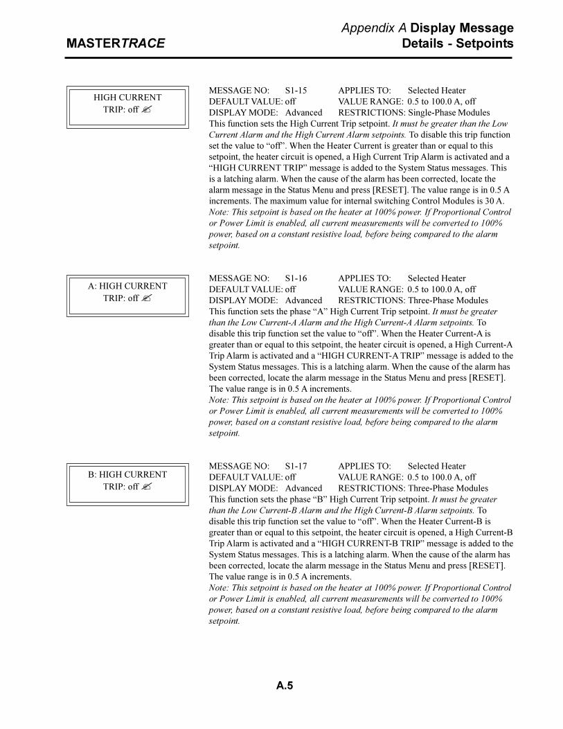
A.5
MASTERTRACEAppendix A Display Message
Details - Setpoints
MESSAGE NO: S1-15 APPLIES TO: Selected HeaterDEFAULT VALUE: off VALUE RANGE: 0.5 to 100.0 A, offDISPLAY MODE: Advanced RESTRICTIONS: Single-Phase ModulesThis function sets the High Current Trip setpoint. It must be greater than the LowCurrent Alarm and the High Current Alarm setpoints. To disable this trip functionset the value to �off�. When the Heater Current is greater than or equal to thissetpoint, the heater circuit is opened, a High Current Trip Alarm is activated and a�HIGH CURRENT TRIP� message is added to the System Status messages. Thisis a latching alarm. When the cause of the alarm has been corrected, locate thealarm message in the Status Menu and press [RESET]. The value range is in 0.5 Aincrements. The maximum value for internal switching Control Modules is 30 A.Note: This setpoint is based on the heater at 100% power. If Proportional Controlor Power Limit is enabled, all current measurements will be converted to 100%power, based on a constant resistive load, before being compared to the alarmsetpoint.
MESSAGE NO: S1-16 APPLIES TO: Selected HeaterDEFAULT VALUE: off VALUE RANGE: 0.5 to 100.0 A, offDISPLAY MODE: Advanced RESTRICTIONS: Three-Phase ModulesThis function sets the phase �A� High Current Trip setpoint. It must be greaterthan the Low Current-A Alarm and the High Current-A Alarm setpoints. Todisable this trip function set the value to �off�. When the Heater Current-A isgreater than or equal to this setpoint, the heater circuit is opened, a High Current-ATrip Alarm is activated and a �HIGH CURRENT-A TRIP� message is added to theSystem Status messages. This is a latching alarm. When the cause of the alarm hasbeen corrected, locate the alarm message in the Status Menu and press [RESET].The value range is in 0.5 A increments.Note: This setpoint is based on the heater at 100% power. If Proportional Controlor Power Limit is enabled, all current measurements will be converted to 100%power, based on a constant resistive load, before being compared to the alarmsetpoint.
MESSAGE NO: S1-17 APPLIES TO: Selected HeaterDEFAULT VALUE: off VALUE RANGE: 0.5 to 100.0 A, offDISPLAY MODE: Advanced RESTRICTIONS: Three-Phase ModulesThis function sets the phase �B� High Current Trip setpoint. It must be greaterthan the Low Current-B Alarm and the High Current-B Alarm setpoints. Todisable this trip function set the value to �off�. When the Heater Current-B isgreater than or equal to this setpoint, the heater circuit is opened, a High Current-BTrip Alarm is activated and a �HIGH CURRENT-B TRIP� message is added to theSystem Status messages. This is a latching alarm. When the cause of the alarm hasbeen corrected, locate the alarm message in the Status Menu and press [RESET].The value range is in 0.5 A increments.Note: This setpoint is based on the heater at 100% power. If Proportional Controlor Power Limit is enabled, all current measurements will be converted to 100%power, based on a constant resistive load, before being compared to the alarmsetpoint.
HIGH CURRENTTRIP: off ?
A: HIGH CURRENTTRIP: off ?
B: HIGH CURRENTTRIP: off ?

A.6
MASTERTRACEAppendix A Display Message
Details - Setpoints
MESSAGE NO: S1-18 APPLIES TO: Selected HeaterDEFAULT VALUE: off VALUE RANGE: 0.5 to 100.0 A, offDISPLAY MODE: Advanced RESTRICTIONS: Three-Phase Modules OnlyThis function sets the phase �C� High Current Trip setpoint. It must be greaterthan the Low Current-C Alarm and the High Current-C Alarm setpoints. Todisable this trip function set the value to �off�. When the Heater Current-C isgreater than or equal to this setpoint, the heater circuit is opened, a High Current-CTrip Alarm is activated and a �HIGH CURRENT-C TRIP� message is added to theSystem Status messages. This is a latching alarm. When the cause of the alarm hasbeen corrected, locate the alarm message in the Status Menu and press[RESET].The value range is in 0.5 A increments.Note: This setpoint is based on the heater at 100% power. If Proportional Controlor Power Limit is enabled, all current measurements will be converted to 100%power, based on a constant resistive load, before being compared to the alarmsetpoint.
MESSAGE NO: S1-19 APPLIES TO: Selected HeaterDEFAULT VALUE: off VALUE RANGE: 0.5 to 100.0 A, offDISPLAY MODE: Advanced RESTRICTIONS: Solid-State Modules OnlyThis function sets the maximum average current that flows in the heater circuit. Itis useful for limiting the inrush current of self regulating cable or to reducing thepower output of constant wattage heaters. Set the value below the breaker rating orto the maximum power desired (Wattage = Heater Voltage x Power Limit value).The value range is in 0.5 A increments. The maximum value for internal switchingControl Modules is 30 A.
MESSAGE NO: S1-20 APPLIES TO: Selected HeaterDEFAULT VALUE: 50 mA VALUE RANGE: 10 to 1000 mA, offDISPLAY MODE: Advanced RESTRICTIONS: NoneThis function sets the Ground Fault Trip setpoint. It must be greater than theGround Fault Alarm setpoint. To disable this trip alarm set the value to �off�.When the Ground Fault Current is greater than or equal to this setpoint, the heatercircuit is opened, the Ground Fault Trip Alarm is activated and a �GROUNDFAULT TRIP� message is added to the System Status messages. This is a latchingalarm. When the cause of the alarm has been corrected, locate the alarm messagein the Status Menu and press [RESET]. The value range is in 5 mA increments.
MESSAGE NO: S1-21 APPLIES TO: Selected HeaterDEFAULT VALUE: 25 mA VALUE RANGE: 10 to 1000 mA, offDISPLAY MODE: All RESTRICTIONS: NoneThis function sets the Ground Fault Alarm setpoint. It must be less than theGround Fault Trip setpoint. To disable this alarm set the value to �off�. When theGround Fault Current is greater than or equal to this setpoint, the Ground FaultAlarm is activated and a �GROUND FAULT ALARM� message is added to theSystem Status messages. The alarm deactivates when the Ground Fault Currentfalls below this alarm setpoint. The value range is in 5 mA increments.
C: HIGH CURRENTTRIP: off ?
POWER LIMIT CURRENT:20.5A ?
GROUND FAULTTRIP: 100mA ?
GROUND FAULTALARM: 20mA ?

A.7
MASTERTRACEAppendix A Display Message
Details - Setpoints
MESSAGE NO: S1-22 APPLIES TO: Selected HeaterDEFAULT VALUE: off VALUE RANGE: 1 to 24 hours, offDISPLAY MODE: Advanced RESTRICTIONS: NoneThis function sets the frequency at which TraceCheck� is activated.TraceCheck� is a feature that exercises the system by automatically applyingpower to the heater for about 30 seconds. If an alarm condition is detected duringthis period, then the TraceCheck� Alarm is activated and a �ALARM DURINGTRACECHECK� message is added to the System Status messages If a groundfault is detected, the heater circuit is opened. This is a latching alarm. To clear thealarm, locate the alarm message in the Status Menu and press [RESET]. To disablethis feature set the value to �off�. TraceCheck� decreases maintenance byproviding an early warning of problems that would otherwise go undetected untilthe heater was needed.
MESSAGE NO: S1-23 APPLIES TO: Selected HeaterDEFAULT VALUE: 120V VALUE RANGE: 100 to 600 V, (measured)DISPLAY MODE: Advanced RESTRICTIONS: noneThis functions sets the Heater Voltage. For 1-point and 2-point Control Moduleswith circuits at 300 V or less, set to �measured�. Otherwise, set to the heatersupply voltage. This value is used to compute Energy Used and Energy Cost.
MESSAGE NO: S1-24 APPLIES TO: Selected HeaterDEFAULT VALUE:off VALUE RANGE: 0 to 300 V, offDISPLAY MODE: Advanced RESTRICTIONS: Single Phase, 1 and 2 point
modulesThis function sets the Low Voltage Alarm setpoint. To disable this alarm set thevalue to �off�. When the Heater Voltage is less than or equal to this setpoint, theLow Voltage Alarm is activated and a �LOW VOLTAGE ALARM� message isadded to the System Status messages. The alarm deactivates when the HeaterVoltage rises above this alarm setpoint.
Setpoints: Heater Setup Menu
MESSAGE NO: S2-01 APPLIES TO: Interface ModuleDEFAULT VALUE: N/A VALUE RANGE: N/ADISPLAY MODE: Advanced RESTRICTIONS: NoneThis message displays the name of the sub-menu when entered.
MESSAGE NO: S2-02 APPLIES TO: Interface ModuleDEFAULT VALUE:Selected Htr VALUE RANGE: Set by MODULE RANGE
functionDISPLAY MODE: Advanced RESTRICTIONS: NoneThis function selects the heater circuit. Each heater circuit has a unique two-partHeater Number. The first part is the Module Number and the second part is theheater circuit within the Control Module. Press [VALUE ñ] or [VALUE ò] andthen press [STORE] to select a heater circuit. For convenience and to reducehuman error, the Heater Name is also displayed.
TRACECHECK CYCLETIME: 4 hours ?
HEATER VOLTAGE:120 V ?
LOW VOLTAGEALARM: 100 V ?
SETPOINTS:HEATER SETUP
SELECT HT: 1-1?NONAME &

A.8
MASTERTRACEAppendix A Display Message
Details - Setpoints
MESSAGE NO: S2-03 APPLIES TO: Selected HeaterDEFAULT VALUE: NONAME VALUE RANGE: 16 Alphanumeric CharactersDISPLAY MODE: Advanced RESTRICTIONS: NoneThis functions sets the Heater Name. It provides a unique, identifiable tag or labelfor each heater circuit. The Heater Name consists of 16 alphanumeric characterswhich are entered one at a time from left to right. The cursor indicates whichcharacter is being selected. Press [VALUEñ] or [VALUE ò] to change thecharacter. Move to the next character by pressing [STORE]. Continue in thisfashion until all 16 characters are entered. Press [STORE] in the last characterposition to save the Heater Name.
MESSAGE NO: S2-04 APPLIES TO: Selected HeaterDEFAULT VALUE: off VALUE RANGE: on, offDISPLAY MODE: Advanced RESTRICTIONS: NoneThis feature sets the response of the heater circuit to the Control Modules MasterOverride input. The Master Override input responds to a contact closure. If theMaster Override is set to �off� or the Master Override inputs are shorted, thencontrol of the heater circuit operates normally based on the Heater Control Tem-perature and the Heater Setpoint. If the Master Override is set to �on� and theMaster Override inputs are open, then the heater circuit is opened regardless of theHeater Control Temperature. This feature allows selected circuits to be turned offfor load shedding or for an ambient temperature override. If the Heater Setpoint isset to �off� or �none� and the Master Override is set to �on�, then the MasterOverride input will have full control over the heater circuit.
MESSAGE NO: S2-05 APPLIES TO: Selected HeaterDEFAULT VALUE: off VALUE RANGE: on, offDISPLAY MODE: Advanced RESTRICTIONS: Solid-State ModulesThis functions minimizes temperature overshoot and undershoot for tightertemperature control. For critical temperature maintenance applications moreaccurate control can be obtained by using this feature. However, the time to reachHeater Setpoint may be longer. With Proportional Control set to �on�, as theHeater Control Temperature approaches the Heater Setpoint, the percent dutycycle of the heater is reduced. With Proportional Control set to �off�, on-offcontrol is used.
MESSAGE NO: S2-06 APPLIES TO: Selected HeaterDEFAULT VALUE: 1 C° VALUE RANGE: 0 to 50 C°DISPLAY MODE: Advanced RESTRICTIONS: Proportional Control must
be �off�This feature sets the size of the DEADBAND for on-off control. Decreasing theDEADBAND increases the temperature control accuracy but also increases theheater switching frequency and wear on mechanical contacts.
HEATER NAME:NONAME?
MASTER OVERRIDE:off ?
PROPORTIONALCONTROL: off ?
DEADBAND5C° ?

A.9
MASTERTRACEAppendix A Display Message
Details - Setpoints
MESSAGE NO: S2-07 APPLIES TO: Selected HeaterDEFAULT VALUE: off VALUE RANGE: on, offDISPLAY MODE: Advanced RESTRICTIONS: NoneThis function sets the heater fail-safe state. The Control Module detects if thetemperature sensor has failed. In this case it will use only the second RTD input, ifavailable, or it will set the heater to its fail-safe state. For freeze protection wherethere is no hazard from over heating, set to �on� to prevent freeze up. Where thereis a potential hazard from over heating, set to �off�.
MESSAGE NO: S2-08 APPLIES TO: Selected HeaterDEFAULT VALUE: 1 RTD VALUE RANGE: See list belowDISPLAY MODE: Advanced RESTRICTIONS: Dual RTD ModulesThis function sets how the Heater Control Temperature is derived from dual RTDinputs as follows.Value Heater Control Temperature1 RTD RTD-ARTD B HT cutoff RTD-A but less than RTD-B2 RTDs, lowest Minimum of RTD-A & RTD-B2 RTDs, highest Maximum of RTD-A & RTD-B2 RTDs, averaged Average of RTD-A & RTD-B2 RTDs, backup RTD-A if okay, else RTD-BWhen RTD B HT cutoff is selected, RTD_B temperature is compared with thehigh temperature alarm. When RTD-B temperature is equal to or greater than thehigh tempertaure alarm setting the heater is turned off regardless if RTD-A tem-perature is less than the heater setpoint.
Setpoints: System Setup Menu
MESSAGE NO: S3-01 APPLIES TO: Interface ModuleDEFAULT VALUE: N/A VALUE RANGE: N/ADISPLAY MODE: All RESTRICTIONS: NoneThis message displays the name of the sub-menu when entered.
MESSAGE NO: S3-02 APPLIES TO: Interface ModuleDEFAULT VALUE: MOD: 1 VALUE RANGE: MOD: Set by MODULE
SEL: no RANGESEL: yes, no
DISPLAY MODE: Advanced RESTRICTIONS: MR100 InterfaceThis function selects which Control Modules are monitored. All Control Modulesthat are to be monitored from the Interface Module must have SEL set to �yes�. AllControl Modules that are not physically connected to the Interface Module musthave SEL set to �no�. With the cursor to the right of MOD choose the ModuleNumber by pressing [VALUE ñ] or [VALUE ò] and then [STORE]. With thecursor to the right of SEL select �yes� to select or �no� to deselect the ControlModule for monitoring by pressing [VALUE ñ] or [VALUE ò] and then[STORE].
IF RTD FAILSHEATER GOES: off ?
RTD MODE:1 RTD ?
SETPOINTS:SYSTEM SETUP
MODULE LISTMOD:1? SEL:yes ?
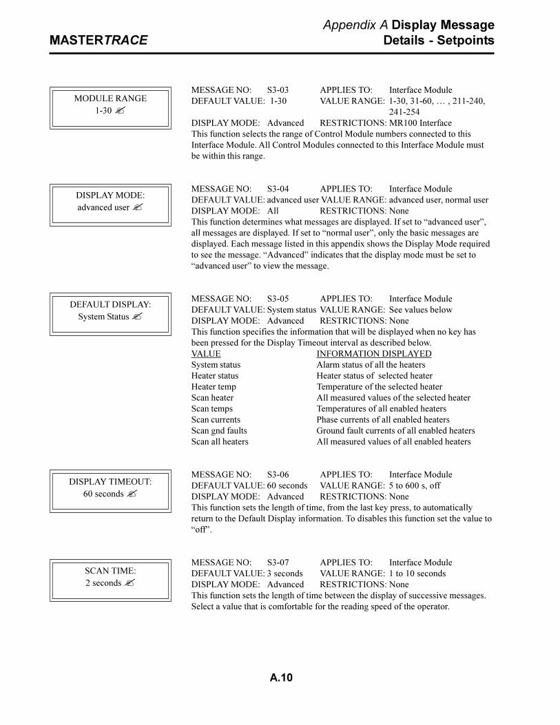
A.10
MASTERTRACEAppendix A Display Message
Details - Setpoints
MESSAGE NO: S3-03 APPLIES TO: Interface ModuleDEFAULT VALUE: 1-30 VALUE RANGE: 1-30, 31-60, � , 211-240,
241-254DISPLAY MODE: Advanced RESTRICTIONS: MR100 InterfaceThis function selects the range of Control Module numbers connected to thisInterface Module. All Control Modules connected to this Interface Module mustbe within this range.
MESSAGE NO: S3-04 APPLIES TO: Interface ModuleDEFAULT VALUE: advanced user VALUE RANGE: advanced user, normal userDISPLAY MODE: All RESTRICTIONS: NoneThis function determines what messages are displayed. If set to �advanced user�,all messages are displayed. If set to �normal user�, only the basic messages aredisplayed. Each message listed in this appendix shows the Display Mode requiredto see the message. �Advanced� indicates that the display mode must be set to�advanced user� to view the message.
MESSAGE NO: S3-05 APPLIES TO: Interface ModuleDEFAULT VALUE: System status VALUE RANGE: See values belowDISPLAY MODE: Advanced RESTRICTIONS: NoneThis function specifies the information that will be displayed when no key hasbeen pressed for the Display Timeout interval as described below.VALUE INFORMATION DISPLAYEDSystem status Alarm status of all the heatersHeater status Heater status of selected heaterHeater temp Temperature of the selected heaterScan heater All measured values of the selected heaterScan temps Temperatures of all enabled heatersScan currents Phase currents of all enabled heatersScan gnd faults Ground fault currents of all enabled heatersScan all heaters All measured values of all enabled heaters
MESSAGE NO: S3-06 APPLIES TO: Interface ModuleDEFAULT VALUE: 60 seconds VALUE RANGE: 5 to 600 s, offDISPLAY MODE: Advanced RESTRICTIONS: NoneThis function sets the length of time, from the last key press, to automaticallyreturn to the Default Display information. To disables this function set the value to�off�.
MESSAGE NO: S3-07 APPLIES TO: Interface ModuleDEFAULT VALUE: 3 seconds VALUE RANGE: 1 to 10 secondsDISPLAY MODE: Advanced RESTRICTIONS: NoneThis function sets the length of time between the display of successive messages.Select a value that is comfortable for the reading speed of the operator.
MODULE RANGE1-30 ?
DISPLAY MODE:advanced user ?
DEFAULT DISPLAY:System Status ?
DISPLAY TIMEOUT:60 seconds ?
SCAN TIME:2 seconds ?

A.11
MASTERTRACEAppendix A Display Message
Details - Setpoints
MESSAGE NO: S3-08 APPLIES TO: Interface ModuleDEFAULT VALUE: Celsius VALUE RANGE: Celsius, FahrenheitDISPLAY MODE: Advanced RESTRICTIONS: NoneThis function sets the units of measure for temperature. All temperatures aredisplayed in the selected units of either Celsius degrees (C°) or Fahrenheit degrees(F°).
MESSAGE NO: S3-09 APPLIES TO: Selected Control ModuleDEFAULT VALUE: $0.05 VALUE RANGE: $0.01 to $0.50DISPLAY MODE: Advanced RESTRICTIONS: NoneThis function sets the COST PER kWh. This value is used to calculate EnergyCost.
MESSAGE NO: S3-10 APPLIES TO: Selected Control ModuleDEFAULT VALUE: off VALUE RANGE: on, offDISPLAY MODE: Advanced RESTRICTIONS: NoneThis feature staggers the power up of heater circuits to eliminate tripping of themain breaker. For all Control Modules with this value set to �on� the followingsequence occurs at power up based on a minimum of 10 circuits. About 10% of theheaters circuits are turned on, there is a one minute delay and then the next 10%are turned on until all circuits are energized.Note: Stagger Start is a module setpoint, if this setpoint is set to �on�, StaggerStart will only be applied to the selected module. Stagger Start will not be appliedto the whole system.
MESSAGE NO: S3-11 APPLIES TO: Selected Control ModuleDEFAULT VALUE: Solid-state VALUE RANGE: Solid-state, MechanicalDISPLAY MODE: Advanced RESTRICTIONS: Solid State ModuleThis function sets the type of switch used on the control module. Switch type iseither solid-state or mechanical. When mechanical is selected, powerlimit andproportional control functions are disabled because both functions switch heatercurrent at the zero cross points, very rapidly, and can damage mechanical switches.Note: Switch Type is a module setpoint, and the stored value will only be appliedto the selected module.
MESSAGE NO: S3-12 APPLIES TO: Interface ModuleDEFAULT VALUE: 1200 VALUE RANGE: 600,1200,2400,4800,9600DISPLAY MODE: Advanced RESTRICTIONS: MR100 Interface ModuleThis function sets the communication baud rate for the MR100 serial port .
MESSAGE NO: S3-13 APPLIES TO: Interface ModuleDEFAULT VALUE: 1200 VALUE RANGE: 600,1200,2400,4800,9600DISPLAY MODE: Advanced RESTRICTIONS: NoneThis function sets the communication baud rate for serial port #1 of the controller.If the display interface is an ML100, the baud rate applies to the control module itis connected to. If the display interface is an MR100, the baud rate applies to serialport #1 of the module selected.
TEMPERATURE UNITS:Celcius ?
COST PER kWh:$0.05 ?
STAGGER START:on ?
SWITCH TYPE:none ?
BAUD RATE MR100:1200 ?
BAUD RATE 1:1200 ?

A.12
MASTERTRACEAppendix A Display Message
Details - Setpoints
MESSAGE NO: S3-14 APPLIES TO: Interface ModuleDEFAULT VALUE: 1200 VALUE RANGE: 600,1200,2400,4800,9600DISPLAY MODE: Advanced RESTRICTIONS: NoneThis function sets the communication baud rate for serial port #2 of the controlmodule that the ML100 display is connected to. If the display interface is anMR100, the baud rate applies to serial port #2 of the module selected.
MESSAGE NO: S3-15 APPLIES TO: Interface ModuleDEFAULT VALUE: alarm:off VALUE RANGE: alarm:off, alarm:on
flash/on, flash/offDISPLAY MODE: Advanced RESTRICTIONS: NoneThis function determines the response of the alarm light output to an alarm. Thealarm light output is design to drive a 12Vdc LED. If the value is set to �alarmoff�, the alarm light is on in a no alarm condition and turns off when alarms arepresent. The �alarm off� setting works best with a green LED for fail-safe modewhere loss of power or a burnt out LED generates an alarm condition. Value�alarm on�, turns the alarm light off in a no alarm condition and turns on whenalarms are present. Value �alarm flash/on� flashes the alarm light when alarms arepresent and turns on the alarm light when there are no alarms. Value �alarm flash/off� flashes the alarm light when alarms are present and turns off the alarm lightwhen there are no alarms.
MESSAGE NO: S3-16 APPLIES TO: Interface ModuleDEFAULT VALUE: MECH:NC VALUE RANGE: MECH:NO SS:NO
SS:NC MECH:NO SS:NCMECH:NC SS:NOMECH:NC SS:NC
DISPLAY MODE: Advanced RESTRICTIONS: NoneConfigures the alarm contacts for normally open (NO) or normally closed (NC).MECH refers to the mechanical alarm contacts on terminals 6 and 7of the ControlModule and terminals 904 and 905 of the MR100 Interface Module. SS refers tothe solid-state dc alarm contacts on terminals 4 and 5 of the Control Module andterminals 906 and 907 of the MR100 Interface Module. In NO mode, contactcloses during alarm condition. In NC mode, contacts open during alarm condi-tion.
MESSAGE NO: S3-17 APPLIES TO: Interface ModuleDEFAULT VALUE: 1 VALUE RANGE: 1-254DISPLAY MODE: Advanced RESTRICTIONS: ML100 Interface ModuleThis function changes the Module Number of the Control Module connected tothe ML100 Interface.
BAUD RATE 2:1200 ?
ALARM LIGHT MODE:alarm: off ?
ALARM CONTACTS:MECH:NC ? SS:NC ?
SET MODULENUMBER: 1 ?

A.13
MASTERTRACEAppendix A Display Message
Details - Setpoints
MESSAGE NO: S3-18 APPLIES TO: Address Enabled ControlModule
DEFAULT VALUE: no VALUE RANGE:yes, noDISPLAY MODE: Advanced RESTRICTIONS: MR100 Interface ModuleThis function resets all values of the Control Module which has been placed inAddress Enabled mode. Select �yes� to proceed. Select �yes� again to confirm.This message asks you to confirm that the Control Module Address is �enabled�.The Control Module Address light must be on. Press [MSSG ò] to proceed.Refer Chapter 5.1.2.
MESSAGE NO: S3-18a APPLIES TO: Address Enabled ControlModule
DEFAULT VALUE: None VALUE RANGE: NoneDISPLAY MODE: Advanced RESTRICTIONS: MR100 Interface ModuleThis message provides a last chance to confirm the Reset Module function. Press[MSSG ò] to continue.
This message asks you to disable Address Mode and check that the ControlModule Address LED is off. Press [MSSG ò] to continue. Refer to Chapter5.1.2.
CONT - MSSG DOWNABORT - RESET
ô
SET ADDR ENABLEADDRESS LED ON
yes [STORE]
ARE YOU SURE?no ?
RESET CONTROLMODULE? no ?
yes [STORE]
ABOUT TO RESETMODULE
CONT - MSSG DOWNABORT - RESET
ô
[MSSGò]
MODULE RESET
PRESS MSSG DOWNTO CONTINUE
ô
SET ADDR DISABLEADDRESS LED OFF
[MSSGò]
ô
PRESS MSSG DOWNTO CONTINUE

A.14
MASTERTRACEAppendix A Display Message
Details - Setpoints
MESSAGE NO: S3-18b APPLIES TO: Address Enabled ControlModule
DEFAULT VALUE: None VALUE RANGE: NoneDISPLAY MODE: Advanced RESTRICTIONS: MR100 Interface ModuleIf you receive the message �NO RESPONSE ��, check that the Control ModuleAddress is �enabled� or refer to Appendix C: Summary of Alarms and theirCauses, NO RESPONSE ALARM. Press [MSSG ò] to proceed.
PRESS MSSG DOWNTO CONTINUE
NO RESPONSEADDRESS LED OFF?
CONT - MSSG DOWNABORT - RESET
SET ADDR ENABLEADDRESS LED ON
ENTER MODULE #:1 ?
[STORE]
ô
ô
yes [STORE]
ARE YOU SURE?no ?
SET MODULENUMBER? no ?
yes [STORE]
NO RESPONSEADDRESS LED OFF?
PRESS MSSG DOWNTO CONTINUE
ô
MESSAGE NO: S3-19 APPLIES TO: Address Enabled ControlModule
DEFAULT VALUE: no VALUE RANGE: yes, noDISPLAY MODE: Advanced RESTRICTIONS: MR100 Interface ModuleThis function changes the Module Number of a connected Control Module whichhas been placed in Address Enabled mode. Select �yes� to proceed. Select �yes�again to confirm.
Enter the new Module Number. The Module Number of each Control Module on adata highway or connected to a MR100 Interface Module must be unique. Selectthe Module Number by pressing [VALUE ñ] or [VALUE ò] and then [STORE].
This message asks you to confirm that the Control Module Address is �enabled�.The Control Module Address light must be on. Press [MSSG ò] to proceed. Referto Chapter 5.1.2.
MESSAGE NO: S3-19a APPLIES TO: Address Enabled ControlModule
DEFAULT VALUE: None VALUE RANGE: NoneDISPLAY MODE: Advanced RESTRICTIONS: MR100 Interface ModuleIf you receive the message �NO RESPONSE ��, check that the Control ModuleAddress is �enabled� or refer to Appendix C: Summary of Alarms and theirCauses, NO RESPONSE ALARM. Press [MSSG ò] to proceed.

A.15
MASTERTRACEAppendix A Display Message
Details - Setpoints
MESSAGE NO: S3-19b APPLIES TO: Address Enabled ControlModule
DEFAULT VALUE: None VALUE RANGE: Module RangeDISPLAY MODE: Advanced RESTRICTIONS: MR100 Interface ModuleThe message �CHECKING MODULE NUMBER: n� is displayed while thesystem looks for a module that already has this number. If it finds a module withthis number, the message �MODULE # 1 ALREADY EXISTS� is displayed.Press [MSSG ò] to continue. A different Module Number must be selected.If the Checking Module Number function is successful, message number S3-19c isdisplayed.
PRESS MSSG DOWNTO CONTINUE
MODULE #1 &ALREADY EXISTS
CHECKING MODULENUMBER: 1 &
ô
ô
MESSAGE NO: S3-19c APPLIES TO: Address Enabled ControlModule
DEFAULT VALUE: None VALUE RANGE: NoneDISPLAY MODE: Advanced RESTRICTIONS: MR100 Interface ModuleThis message provides a last chance to confirm the Module Number Change.Press [MSSG ò] to proceed.
This message indicates that the SET MODULE Number function was successful.Press [MSSG ò] to continue.
This message asks you to disable Address Mode and check that the ControlModule Address LED is off. Press [MSSG ò] to continue. Refer to Chapter 5.1.2.
ABOUT TO SETNEW NUMBER
CONT - MSSG DOWNABORT - RESET
ô
ô
MODULE NUMBERASSIGNED
ô
PRESS MSSG DOWNTO CONTINUE
ô
SET ADDR DISABLEADDRESS LED OFF
ô
PRESS MSSG DOWNTO CONTINUE

A.16
MASTERTRACEAppendix A Display Message
Details - Setpoints
PRESS MSSG DOWNTO CONTINUE
NO RESPONSEADDRESS LED OFF?
CONT - MSSG DOWNABORT - RESET
SET ADDR ENABLEADDRESS LED ON
ARE YOU SURE?no ?
READ MODULENUMBER? no ?
yes ò
yes ò
ô
MESSAGE NO: S3-20 APPLIES TO: Address Enabled ControlModule
DEFAULT VALUE: no VALUE RANGE: yes, noDISPLAY MODE: Advanced RESTRICTIONS: MR100 Interface ModuleThis function reads the Module Number of a Control Module with AddressEnabled. The Module Number of each Control Module on a data highway orconnected to a MR100 Interface Module is unique. Select �yes� to proceed. Select�yes� again to confirm.
This message asks you to confirm that the Control Module Address is �enabled�.The Control Module Address light must be on. Press [MSSG ò] to proceed. Referto Chapter 5.1.2.
ô
MESSAGE NO: S3-20a APPLIES TO: Address Enabled ControlModule
DEFAULT VALUE: None VALUE RANGE: NoneDISPLAY MODE: Advanced RESTRICTIONS: MR100 Interface ModuleIf you receive the message �NO RESPONSE ��, check that the Control ModuleAddress is �enabled� or refer to Appendix C: Summary of Alarms and theirCauses, NO RESPONSE ALARM. Press [MSSG ò] to proceed.
MESSAGE NO: S3-20b APPLIES TO: Address Enabled ControlModule
DEFAULT VALUE: None VALUE RANGE: Module RangeDISPLAY MODE: Advanced RESTRICTIONS: MR100 Interface ModuleThis message displays the Module Number and indicates that the READ MOD-ULE function was successful. Press [MSSG ò] to proceed.
This message asks you to disable Address Mode and check that the ControlModule Address LED is off. Press [MSSG ò] to continue. Refer to Chapter 5.1.2.
MODULE NUMBER1 &
ô
PRESS MSSG DOWNTO CONTINUE
SET ADDR DISABLEADDRESS LED OFF
ô
PRESS MSSG DOWNTO CONTINUE
[MSSGò]

A.17
MASTERTRACEAppendix A Display Message
Details - Setpoints
MR100CLEARED
yes [STORE]
ARE YOU SURE?no ?
RESET MR100?no ?
yes [STORE]
MESSAGE NO: S3-21 APPLIES TO: MR100 Interface ModuleDEFAULT VALUE: no VALUE RANGE: yes, noDISPLAY MODE: Advanced RESTRICTIONS: MR100 Interface ModuleThis function resets all values of the MR100 Interface Module to the defaultvalues. Select �yes� to proceed. Select �yes� again to confirm.
This message confirms that the MR100 Interface Module was reset.
FIRMWARE VERSIOND1-02-01
MESSAGE NO: S3-22 APPLIES TO: Interface ModuleDEFAULT VALUE: N/A VALUE RANGE: N/ADISPLAY MODE: Advanced RESTRICTIONS: NoneThis message displays the firmware version number.
MESSAGE NO: S3-23 APPLIES TO: Interface ModuleDEFAULT VALUE: N/A VALUE RANGE: N/ADISPLAY MODE: Advanced RESTRICTIONS: NoneThis message displays the operation manual version or reorder number.
MESSAGE NO: S3-24 APPLIES TO: Interface ModuleDEFAULT VALUE: N/A VALUE RANGE: N/ADISPLAY MODE: Advanced RESTRICTIONS: NoneThis message displays the factory telephone number.
MANUAL VERSION:1501-0006_1
FOR ASSISTANCE:(403)735-9555

A.18
MASTERTRACEAppendix A Display Message
Details - Setpoints
MESSAGE NO: S4-01 APPLIES TO: Interface ModuleDEFAULT VALUE: N/A VALUE RANGE: N/ADISPLAY MODE: All RESTRICTIONS: NoneThis message displays the name of the sub-menu when entered.
MESSAGE NO: S4-02 APPLIES TO: Selected Control ModuleDEFAULT VALUE: disabled VALUE RANGE: 1 to 24 hrs, disabled,
on continuouslyDISPLAY MODE: Advanced RESTRICTIONS: NoneThis function manually overrides heater control for maintenance purposes. Fornormal operation set to �disable�. If a period of time is selected, the heater isforced on for the selected interval. If �on continuously� is selected, the heater isforced on until �disabled� is selected.
MESSAGE NO: S4-03 APPLIES TO: Selected Control ModuleDEFAULT VALUE: disabled VALUE RANGE: 1 to 24 hrs, disabled,
on continuouslyDISPLAY MODE: Advanced RESTRICTIONS: NoneThis function manually controls of the alarm output for maintenance purposes. Fornormal operation set to �disable�. If a period of time is selected, the alarm outputis forced on for the selected interval. If �on continuously� is selected, the alarmoutput is forced on until �disabled� is selected.
MESSAGE NO: S4-04 APPLIES TO: Interface ModuleDEFAULT VALUE: disabled VALUE RANGE: enabled, disabledDISPLAY MODE: All RESTRICTIONS: MR100 Interface ModuleThis function manually controls of the alarm output for maintenance purposes. Fornormal operation set to �disabled�. If �enabled� is selected, the alarm output isforced on until �disabled� is selected.
MESSAGE NO: S4-05 APPLIES TO: Selected Control ModuleDEFAULT VALUE: test now VALUE RANGE: 1 to 24 hrs, test now, disableDISPLAY MODE: Advanced RESTRICTIONS: 5 and 10 Point ModulesThis function will test the ground fault CTs on the controller to ensure they aresensing ground fault. The ground fault test wire is looped through all the groundfault CTs. On the mechanical switching modules, the wire is looped internally.When ground fault test is turned on, the controller applies an ac current above50mA and checks the measured ground fault current. If the controller measures atest current below 50mA the GF Test Alarm is activated and a �GF CT� message isadded to the system status messages. This is a latching alarm. When the cause ofthe alarm has been corrected, locate the alarm message in the Status Menu andpress [RESET]. If all GF CTs pass the GF test, no alarm is displayed.
Setpoints: Test Menu
MANUAL ALARM:disabled ?
SETPOINTSTEST
MANUAL HEATERdisabled ?
MANUAL SYSTEMALARM: disabled ?
GF TESTtest now ?
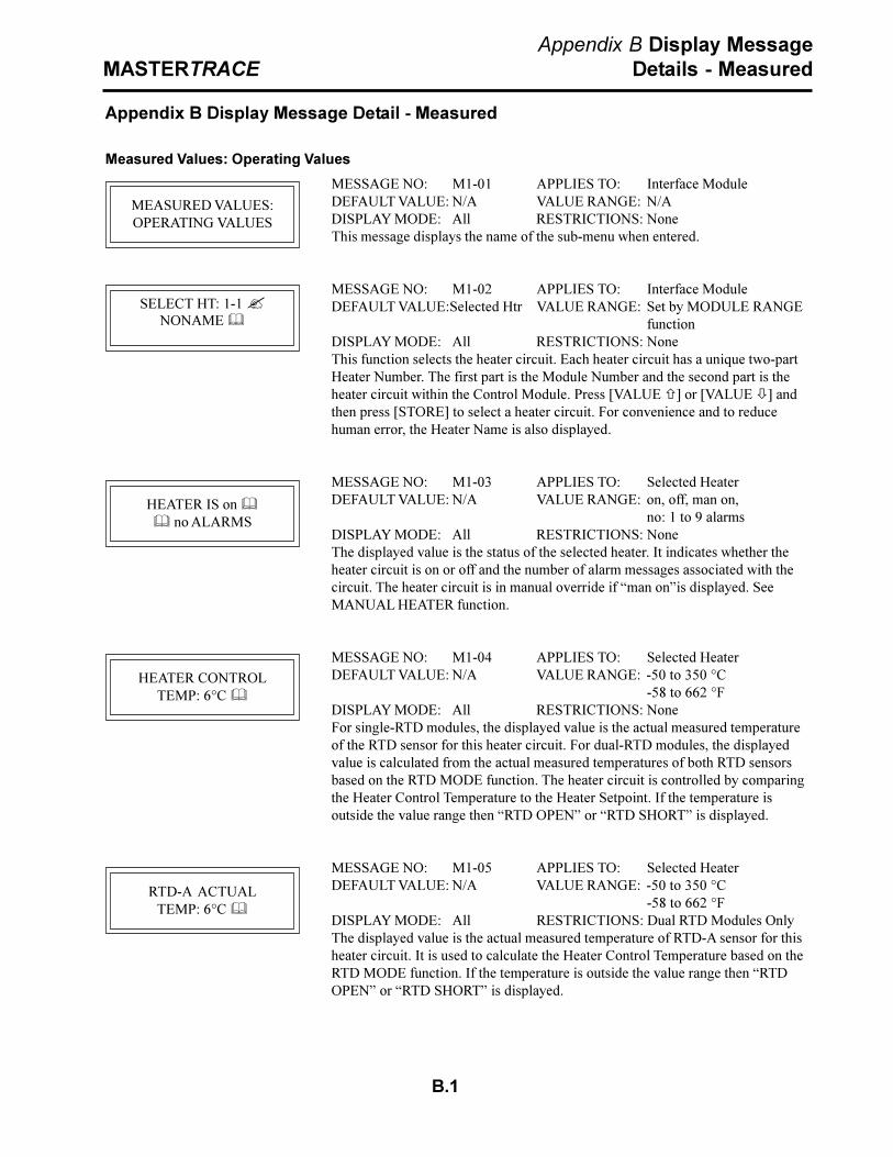
B.1
MASTERTRACEAppendix B Display Message
Details - Measured
MESSAGE NO: M1-01 APPLIES TO: Interface ModuleDEFAULT VALUE: N/A VALUE RANGE: N/ADISPLAY MODE: All RESTRICTIONS: NoneThis message displays the name of the sub-menu when entered.
MESSAGE NO: M1-02 APPLIES TO: Interface ModuleDEFAULT VALUE:Selected Htr VALUE RANGE: Set by MODULE RANGE
functionDISPLAY MODE: All RESTRICTIONS: NoneThis function selects the heater circuit. Each heater circuit has a unique two-partHeater Number. The first part is the Module Number and the second part is theheater circuit within the Control Module. Press [VALUE ñ] or [VALUE ò] andthen press [STORE] to select a heater circuit. For convenience and to reducehuman error, the Heater Name is also displayed.
MESSAGE NO: M1-03 APPLIES TO: Selected HeaterDEFAULT VALUE: N/A VALUE RANGE: on, off, man on,
no: 1 to 9 alarmsDISPLAY MODE: All RESTRICTIONS: NoneThe displayed value is the status of the selected heater. It indicates whether theheater circuit is on or off and the number of alarm messages associated with thecircuit. The heater circuit is in manual override if �man on�is displayed. SeeMANUAL HEATER function.
MESSAGE NO: M1-04 APPLIES TO: Selected HeaterDEFAULT VALUE: N/A VALUE RANGE: -50 to 350 °C
-58 to 662 °FDISPLAY MODE: All RESTRICTIONS: NoneFor single-RTD modules, the displayed value is the actual measured temperatureof the RTD sensor for this heater circuit. For dual-RTD modules, the displayedvalue is calculated from the actual measured temperatures of both RTD sensorsbased on the RTD MODE function. The heater circuit is controlled by comparingthe Heater Control Temperature to the Heater Setpoint. If the temperature isoutside the value range then �RTD OPEN� or �RTD SHORT� is displayed.
MESSAGE NO: M1-05 APPLIES TO: Selected HeaterDEFAULT VALUE: N/A VALUE RANGE: -50 to 350 °C
-58 to 662 °FDISPLAY MODE: All RESTRICTIONS: Dual RTD Modules OnlyThe displayed value is the actual measured temperature of RTD-A sensor for thisheater circuit. It is used to calculate the Heater Control Temperature based on theRTD MODE function. If the temperature is outside the value range then �RTDOPEN� or �RTD SHORT� is displayed.
Appendix B Display Message Detail - Measured
Measured Values: Operating Values
MEASURED VALUES:OPERATING VALUES
SELECT HT: 1-1 ?NONAME &
HEATER IS on && no ALARMS
HEATER CONTROLTEMP: 6°C &
RTD-A ACTUALTEMP: 6°C &

B.2
MASTERTRACEAppendix B Display Message
Details - Measured
MESSAGE NO: M1-06 APPLIES TO: Selected HeaterDEFAULT VALUE: N/A VALUE RANGE: -50 to 350 °C
-58 to 662 °FDISPLAY MODE: All RESTRICTIONS: Dual RTD ModulesThe displayed value is the actual measured temperature of RTD-B sensor for thisheater circuit. It is used to calculate the Heater Control Temperature based on theRTD MODE function. If the temperature is outside the value range then �RTDOPEN� or �RTD SHORT� is displayed.
MESSAGE NO: M1-07 APPLIES TO: Selected HeaterDEFAULT VALUE: N/A VALUE RANGE: 0 to 100%DISPLAY MODE: Advanced RESTRICTIONS: NoneThe displayed value is the percentage duty cycle of the heater circuit. For example,a percentage duty cycle of 30% means that the circuit is energised for 3 out of 10supply cycles.
MESSAGE NO: M1-08 APPLIES TO: Selected HeaterDEFAULT VALUE: N/A VALUE RANGE: 0 to 100.0 ADISPLAY MODE: All RESTRICTIONS: Single-Phase ModulesThe displayed value is the actual single-phase current of the heater circuit. If theheater is off, this value will be zero. The maximum value range for internalswitching modules is 30.0 A. If the current exceeds the value range then �O.L.� isdisplayed. The use of PROPORTIONAL CONTROL or POWER LIMIT functionscan reduce the phase current by reducing the circuit voltage.
MESSAGE NO: M1-09 APPLIES TO: Selected HeaterDEFAULT VALUE: N/A VALUE RANGE: 0 to 100.0 ADISPLAY MODE: All RESTRICTIONS: Three-Phase ModulesThe displayed value is the actual phase-A current of the heater circuit. If the heateris off, this value will be zero. If the current exceeds the value range then �O.L.� isdisplayed. The use of PROPORTIONAL CONTROL or POWER LIMIT functionscan reduce the phase current by reducing the circuit voltage.
MESSAGE NO: M1-10 APPLIES TO: Selected HeaterDEFAULT VALUE: N/A VALUE RANGE: 0 to 100.0 ADISPLAY MODE: All RESTRICTIONS: Three-Phase ModulesThe displayed value is the actual phase-B current of the heater circuit. If the heateris off, this value will be zero. If the current exceeds the value range then �O.L.� isdisplayed. The use of PROPORTIONAL CONTROL or POWER LIMIT functionscan reduce the phase current by reducing the circuit voltage.
MESSAGE NO: M1-11 APPLIES TO: Selected HeaterDEFAULT VALUE: N/A VALUE RANGE: 0 to 100.0 ADISPLAY MODE: All RESTRICTIONS: Three-Phase ModulesThe displayed value is the actual phase-C current of the heater circuit. If the heateris off, this value will be zero. If the current exceeds the value range then �O.L.� isdisplayed. The use of PROPORTIONAL CONTROL or POWER LIMIT functionscan reduce the phase current by reducing the circuit voltage.
RTD-B ACTUALTEMP: 6°C &
HEATER AT 100% &POWER
HEATER CURRENT4.6A &
A:HEATER CURRENT4.6A &
B:HEATER CURRENT4.6A &
C:HEATER CURRENT4.6A &

B.3
MASTERTRACEAppendix B Display Message
Details - Measured
MESSAGE NO: M1-12 APPLIES TO: Selected HeaterDEFAULT VALUE: N/A VALUE RANGE: 0 to 300 VDISPLAY MODE: All RESTRICTIONS: Single-pole 1 and 2 point
modulesThe displayed value is the measured supply voltage.
MESSAGE NO: M1-13 APPLIES TO: Selected HeaterDEFAULT VALUE: N/A VALUE RANGE: 0 to 1000 mADISPLAY MODE: All RESTRICTIONS: NoneThe displayed value is the ground leakage or ground fault current. If the currentexceeds the value range then �O.L.� is displayed.
Measured Values: Statistics Menu
MESSAGE NO: M2-01 APPLIES TO: Interface ModuleDEFAULT VALUE: N/A VALUE RANGE: N/ADISPLAY MODE: Advanced RESTRICTIONS: NoneThis message displays the name of the sub-menu when entered.
MESSAGE NO: M2-02 APPLIES TO: Interface ModuleDEFAULT VALUE:Selected Htr VALUE RANGE: Set by MODULE RANGE
functionDISPLAY MODE: Advanced RESTRICTIONS: NoneThis function selects the heater circuit. Each heater circuit has a unique two-partHeater Number. The first part is the Module Number and the second part is theheater circuit within the Control Module. Press [VALUE ñ] or [VALUE ò] andthen press [STORE] to select a heater circuit. For convenience and to reducehuman error, the Heater Name is also displayed.
MESSAGE NO: M2-03 APPLIES TO: Selected HeaterDEFAULT VALUE: N/A VALUE RANGE: -50 to 350 °C
-58 to 662 °FDISPLAY MODE: Advanced RESTRICTIONS: NoneThe displayed value is the lowest Heater Control Temperature since the last reset.If the displayed value is �RTD SHORT�, a value less than the minimum range wasrecorded. To reset the displayed value press [RESET]. To reset with all statisticsuse RESET STATISTICS function.
MESSAGE NO: M2-04 APPLIES TO: Selected HeaterDEFAULT VALUE: N/A VALUE RANGE: -50 to 350 °C
-58 to 662 °FDISPLAY MODE: Advanced RESTRICTIONS: NoneThe displayed value is the highest Heater Control Temperature since the last reset.If the displayed value is �RTD OPEN�, a value greater than the maximum rangewas recorded. To reset the displayed value press [RESET]. To reset with allstatistics use RESET STATISTICS function.
HEATER VOLTAGE120V &
GROUND FAULTCURRENT: 5mA &
MEASURED VALUES:STATISTICS &
SELECT HT: 1-1 ?NONAME &
MIN TEMPERATURE:3°C &
MAX TEMPERATURE:25°C &

B.4
MASTERTRACEAppendix B Display Message
Details - Measured
MESSAGE NO: M2-05 APPLIES TO: Selected HeaterDEFAULT VALUE: N/A VALUE RANGE: 0 to 100.0 ADISPLAY MODE: Advanced RESTRICTIONS: Single-Phase ModulesThe displayed value is the highest Heater Current since the last reset. The maxi-mum value range for internal switching modules is 30.0 A. If the displayed value is�O.L.�, a value greater than the maximum range was recorded. To reset thedisplayed value press [RESET]. To reset with all statistics use RESET STATIS-TICS function.
MESSAGE NO: M2-06 APPLIES TO: Selected HeaterDEFAULT VALUE: N/A VALUE RANGE: 0 to 100.0 ADISPLAY MODE: Advanced RESTRICTIONS: Three-Phase ModulesThe displayed value is the highest Heater Current-A since the last reset. If thedisplayed value is �O.L.�, a value greater than the maximum range was recorded.To reset the displayed value press [RESET]. To reset with all statistics use RESETSTATISTICS function.
MESSAGE NO: M2-07 APPLIES TO: Selected HeaterDEFAULT VALUE: N/A VALUE RANGE: 0 to 100.0 ADISPLAY MODE: Advanced RESTRICTIONS: Three-Phase ModulesThe displayed value is the highest Heater Current-B since the last reset. If thedisplayed value is �O.L.�, a value greater than the maximum range was recorded.To reset the displayed value press [RESET]. To reset with all statistics use RESETSTATISTICS function.
MESSAGE NO: M2-08 APPLIES TO: Selected HeaterDEFAULT VALUE: N/A VALUE RANGE: 0 to 100.0 ADISPLAY MODE: Advanced RESTRICTIONS: Three-Phase ModulesThe displayed value is the highest Heater Current-C since the last reset. If thedisplayed value is �O.L.�, a value greater than the maximum range was recorded.To reset the displayed value press [RESET]. To reset with all statistics use RESETSTATISTICS function.
MESSAGE NO: M2-09 APPLIES TO: Selected HeaterDEFAULT VALUE: N/A VALUE RANGE: 0 to 1000 mADISPLAY MODE: Advanced RESTRICTIONS: NoneThe displayed value is the highest Ground Fault Current since the last reset. If thedisplayed value is �O.L.�, a value greater than the maximum range was recorded.To reset the displayed value press [RESET]. To reset with all statistics use RESETSTATISTICS function.
MESSAGE NO: M2-10 APPLIES TO: Selected HeaterDEFAULT VALUE: N/A VALUE RANGE: 0 to 1000 MWhDISPLAY MODE: Advanced RESTRICTIONS: NoneThe displayed value is the energy used in the last day. Energy is calculated fromthe Heater Current times the Heater Voltage integrated over time. This value isautomatically updated once every 24 hours. It cannot be reset.
MAX HEATER CURRENT4.7A &
A: MAX HEATER CURRENT4.7A &
B: MAX HEATER CURRENT4.7A &
C: MAX HEATER CURRENT4.6A &
MAX GROUND FAULTCURRENT: 6mA &
ENERGY USED LASTDAY: 2.1kWh &

B.5
MASTERTRACEAppendix B Display Message
Details - Measured
MESSAGE NO: M2-11 APPLIES TO: Selected HeaterDEFAULT VALUE: N/A VALUE RANGE: 0 to 1000 MWhDISPLAY MODE: Advanced RESTRICTIONS: NoneThe displayed value is the energy used since the last reset. Energy is calculatedfrom the Heater Current times the Heater Voltage integrated over time. To reset useRESET STATISTICS function.
MESSAGE NO: M2-12 APPLIES TO: Selected HeaterDEFAULT VALUE: N/A VALUE RANGE: $0 to $1,000,000.00DISPLAY MODE: Advanced RESTRICTIONS: NoneThe displayed value is the energy cost in the last day. Energy cost is calculatedfrom the Energy Used times the COST PER kWh. This value is automaticallyupdated once every 24 hours. It cannot be reset.
MESSAGE NO: M2-13 APPLIES TO: Selected HeaterDEFAULT VALUE: N/A VALUE RANGE: $0 to $1,000,000.00DISPLAY MODE: Advanced RESTRICTIONS: NoneThe displayed value is the energy cost since the last reset. Energy cost is calculatedfrom the Energy Used times the COST PER kWh. To reset use RESET STATIS-TICS function.
MESSAGE NO: M2-14 APPLIES TO: Selected HeaterDEFAULT VALUE: N/A VALUE RANGE: 0 to 1,000,000 hoursDISPLAY MODE: Advanced RESTRICTIONS: NoneThe displayed value is the elapsed time since last reset. To reset use RESETSTATISTICS function.
MESSAGE NO: M2-15 APPLIES TO: Selected HeaterDEFAULT VALUE: N/A VALUE RANGE: 0 to 999,999 hoursDISPLAY MODE: Advanced RESTRICTIONS: NoneThe displayed value is the accumulated time that the heater circuit has been onsince the last reset. It indicates how active the heater circuit is and can be usefulfor maintenance. To reset use RESET STATISTICS function.
MESSAGE NO: M2-16 APPLIES TO: Selected HeaterDEFAULT VALUE: N/A VALUE RANGE: 0 to 100%DISPLAY MODE: Advanced RESTRICTIONS: NoneThe displayed value is the percentage of time that the heater circuit has been onsince the last reset. PERCENT ON TIME = HEATER ON TIME ÷ TIME SINCERESET x 100%. It indicates how active the heater circuit is and can be useful formaintenance. Interpretation of this value will depend on the process but largechanges could be an indication of degradation of the heater or the insulation. Toreset use RESET STATISTICS function.
TOTAL ENERGYUSED: 42.2kWh &
ENERGY COST LASTDAY: $1.70 &
TOTAL ENERGYCOST: $33.92 &
TIME SINCE RESET48 hrs &
HEATER ON TIME80 hrs &
HEATER IS ON& 17% OF THE TIME

B.6
MASTERTRACEAppendix B Display Message
Details - Measured
MESSAGE NO: M2-17 APPLIES TO: Selected Control ModuleDEFAULT VALUE: N/A VALUE RANGE: 0 to 1,000,000 hoursDISPLAY MODE: Advanced RESTRICTIONS: NoneThe displayed value is the total time since power was first applied to the InterfaceModule. It is useful for maintenance purposes. It cannot be reset.
MESSAGE NO: M2-18 APPLIES TO: Selected Control ModuleDEFAULT VALUE: N/A VALUE RANGE: yes, noDISPLAY MODE: Advanced RESTRICTIONS: NoneThis function resets all the statistical values except Total Run Time, Energy UsedLast Day and Energy Cost Last Day. Select �yes� and then press [STORE]. Youare asked to confirm your request. Again, select �yes� and then press [STORE].The statistical values are now cleared. If the display interface is an ML100, thisfunction resets the statistical values of all the Control Module heaters. If thedisplay interface is an MR100, this function resets the statistical values of theselected heater.
TOTAL RUN TIME:20966 hrs &
RESET STATISTICS?no ?
ARE YOU SURE?no ?
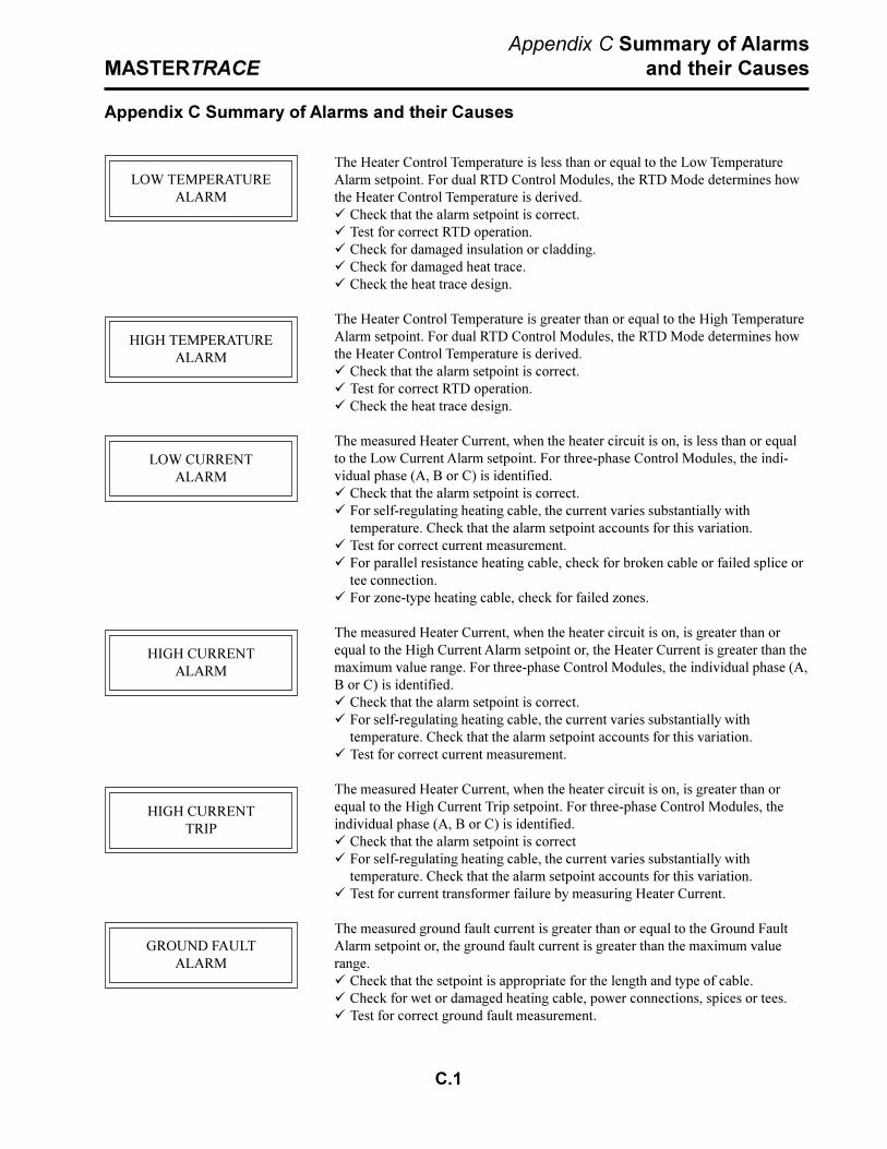
C.1
MASTERTRACEAppendix C Summary of Alarms
and their Causes
The Heater Control Temperature is less than or equal to the Low TemperatureAlarm setpoint. For dual RTD Control Modules, the RTD Mode determines howthe Heater Control Temperature is derived.ü Check that the alarm setpoint is correct.ü Test for correct RTD operation.ü Check for damaged insulation or cladding.ü Check for damaged heat trace.ü Check the heat trace design.
The Heater Control Temperature is greater than or equal to the High TemperatureAlarm setpoint. For dual RTD Control Modules, the RTD Mode determines howthe Heater Control Temperature is derived.ü Check that the alarm setpoint is correct.ü Test for correct RTD operation.ü Check the heat trace design.
The measured Heater Current, when the heater circuit is on, is less than or equalto the Low Current Alarm setpoint. For three-phase Control Modules, the indi-vidual phase (A, B or C) is identified.ü Check that the alarm setpoint is correct.ü For self-regulating heating cable, the current varies substantially with
temperature. Check that the alarm setpoint accounts for this variation.ü Test for correct current measurement.ü For parallel resistance heating cable, check for broken cable or failed splice or
tee connection.ü For zone-type heating cable, check for failed zones.
The measured Heater Current, when the heater circuit is on, is greater than orequal to the High Current Alarm setpoint or, the Heater Current is greater than themaximum value range. For three-phase Control Modules, the individual phase (A,B or C) is identified.ü Check that the alarm setpoint is correct.ü For self-regulating heating cable, the current varies substantially with
temperature. Check that the alarm setpoint accounts for this variation.ü Test for correct current measurement.
The measured Heater Current, when the heater circuit is on, is greater than orequal to the High Current Trip setpoint. For three-phase Control Modules, theindividual phase (A, B or C) is identified.ü Check that the alarm setpoint is correctü For self-regulating heating cable, the current varies substantially with
temperature. Check that the alarm setpoint accounts for this variation.ü Test for current transformer failure by measuring Heater Current.
The measured ground fault current is greater than or equal to the Ground FaultAlarm setpoint or, the ground fault current is greater than the maximum valuerange.ü Check that the setpoint is appropriate for the length and type of cable.ü Check for wet or damaged heating cable, power connections, spices or tees.ü Test for correct ground fault measurement.
Appendix C Summary of Alarms and their Causes
LOW TEMPERATUREALARM
HIGH TEMPERATUREALARM
LOW CURRENTALARM
HIGH CURRENTALARM
HIGH CURRENTTRIP
GROUND FAULTALARM

C.2
MASTERTRACEAppendix C Summary of Alarms
and their Causes
The measured ground fault current is greater than or equal to the Ground FaultTrip setpoint.ü Check that the setpoint is appropriate for the length and type of cable.ü Check for wet or damaged heating cable, power connections, splices or tees.ü Test for correct ground fault measurement.
For single and dual-point Control Modules, the measured circuit voltage is lessthan or equal to the Low Voltage Alarm setpoint.ü Check for voltage input failure by measuring the voltage at the input. On
internal switching modules, check the Heater Power In terminals; on externalswitching modules, check the Heater Voltage terminals.
ü Check for breaker trip.
The temperature derived from the RTD resistance is outside the range of valuesfor Heater Control Temperature.ü Check for damaged RTD, cable or connection.ü Test the RTD input.ü Several RTD Short Alarms indicate an RTD Board failure.ü RTD Open Alarm can indicate that a spare heater circuit is enabled.
The phase current is greater than or equal to 0.1 A when the heater circuit is off.ü Check for switch failure.ü Test the switch input or coil voltage. When the heater circuit is off, the input or
coil voltage should be 0 Vdc. Otherwise the Module needs repair.
One of the following alarms occurred during the TraceCheck� cycle. Refer to thealarm details above for the individual alarm.ü LOW CURRENT ALARMü HIGH CURRENT ALARMü HIGH CURRENT TRIPü GROUND FAULT ALARMü GROUND FAULT TRIPü SWITCH FAILURE ALARM
For the Group Interface Module, indicates that a Control Module does notrespond.ü If module does not exist on the data highway remove from the Module List.ü Check for damaged RS-485 cable.ü Check for Failed Control Module.
A memory or CPU failure has occurred.ü If the alarm message occurs on the ML100 Dedicated Interface Module, the
Control Module needs repair.ü If the alarm occurs on the MR100 Group Interface Module, the Group Inter-face Module needs repair.
Ground fault monitoring function did not detect the GF test current.ü Check ground fault current transformer wiring to terminals.ü Ground fault current transformer may be faulty.
GROUND FAULTTRIP
LOW VOLTAGEALARM
RTD FAILUREALARM
SWITCH FAILUREALARM
ALARM DURINGTRACECHECK
NO RESPONSEALARM
SELF TESTFAILURE ALARM
GF TESTALARM
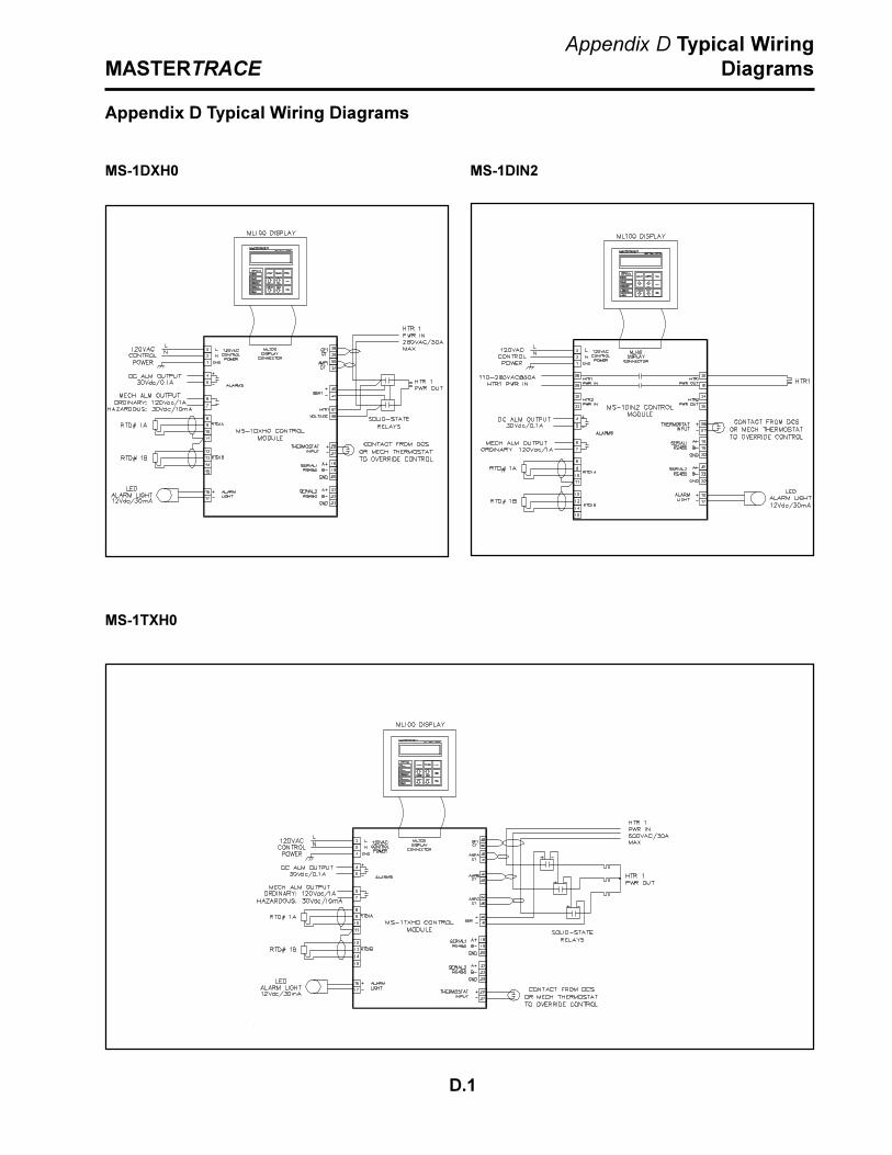
D.1
MASTERTRACEAppendix D Typical Wiring
Diagrams
MS-1DXH0 MS-1DIN2
MS-1TXH0
Appendix D Typical Wiring Diagrams

D.2
MASTERTRACEAppendix D Typical Wiring
Diagrams
MS-2DXH0 MS-2DIN2
MS-5ADXH0

D.3
MASTERTRACEAppendix D Typical Wiring
Diagrams
MS-5ADIN2
MS-5ATXH0

D.4
MASTERTRACEAppendix D Typical Wiring
Diagrams
MS-10ADIN2
MS-10ADXH0

D.5
MASTERTRACEAppendix D Typical Wiring
Diagrams
Driving Contactors
Serial Communications

Warranty
The manufacturer warrants each control that it manufactures to be free fromdefective material or workmanship for a period of 12 months from date ofpurchase.
Under this warranty, the obligation of the manufacturer is limited to repairingor replacing the defective control at its option, when returned to the manufac-turer�s factory with shipping charges prepaid.
If failure has been caused by misuse, incorrect application or alteration of thecontrol, this warranty will be void.
UNLESS SPECIFICALLY PROVIDED FOR IN WRITING IN THIS WAR-RANTY, EACH CONTROL IS PROVIDED WITHOUT ANY WARRANTY OFANY KIND EITHER EXPRESSED OR IMPLIED. IN PARTICULAR, WITH-OUT LIMITING THE GENERALITY OF THE FOREGOING, THE FOLLOW-ING IMPLIED WARRANTIES AND CONDITIONS ARE EXPRESSLY DIS-CLAIMED:
a). ANY IMPLIED WARRANTY OR CONDITION THAT THE CON-TROL WILL MEET YOUR REQUIREMENTS.
b). ANY IMPLIED WARRANTY OR CONDITION THAT THE OP-ERATION OF THE CONTROL WILL BE UNINTERRUPTED ORERROR FREE; AND
c). ANY IMPLIED WARRANTY OR CONDITION OFMERCHANTABILITY OR FITNESS FOR A PARTICULARPURPOSE.
The user shall be made aware that if the equipment is used in a manner notspecified by the manufacturer, the protection provided by the equipment maybe impaired.

MASTERTRACE TM
HEAT TRACING CONTROL
P/N: 1501-0006_1 MT02/00 Printed in Canada
Nextron Corporation 1916 27th Avenue N.E., Calgary, Alberta, T2E 7A5, Tel:(403) 735-9555, Fax: (403) 735-9559