master's thesis - connecting repositories · 3.4.5 multiple matlab sessions ... hnc...
TRANSCRIPT

Czech Technical University in Prague
Faculty of Electrical Engineering
MASTER'S THESIS
2014Petr Procházka


Czech Technical University in Prague
Faculty of electrical engineering
Department of Radio Engineering
Experimental Wireless Cloud TxR TestbedPlatform
May 2014 Author: Petr ProcházkaSupervisor: prof. Ing. Jan Sýkora, CSc.

Proclamation
I declare that I have worked on my diploma thesis independently and onlysources stated in bibliography were used. I agree that my thesis or its parts canbe borrowed and provided to public.
Date: 12.5 2014
.............................
Signature

Task

Acknowledgement
I would like to thank to prof. Ing. Jan Sýkora for his very wise and useful advicesand comments, which helps to create this thesis. Also I would like to thank toall doctoral students from DiRaC group for their help with many obstacles andfor very pleasant and friendly atmosphere establishment.

Abstract:
At this time Wireless Physical Layer Network Coding (WPNC) is a hot topicin research community as a means to enhance the overall network throughput.The main goal of the thesis is to develop, practically build and verify the experi-mental wireless cloud network platform with multiple Tx/Rx for software radios.The platform should be con�gurable to serve various topology and processingscenarios including possibility to emulate simpli�ed processing options such asperfect synchronization or symbol timing. This will involve the development ofAirInterface wrapper protocol in order to de�ne basic rules for communicationin wireless network. The platform should have a user interface which allowsto create a signal from data inputs and also direct work with signal samples(IQ BB) for o�ine processing. Platform should be designed in such a way toprovide some smaller tasks as various modulations, NCM encoder, H-decoding,synchronization options etc. The viability of the platform should be demon-strated by example implementations and real radio hop experiments of selected(both point-2-point, and cloud oriented) scenarios with simple forms of WPNCcomponents.
Key words:
Wireless Physical Layer Network Coding, Synchronization, Platform, AirInter-face protocol
Abstrakt:
V sou£asné dob¥ je Wireless Physical Layer Network Coding (WPNC) st°edemzájmu výzkumník· v oblasti bezdrátových komunikací jako jedna z moºnostíjak docílit výrazného zvý²ení propustnosti t¥chto sítí. Cílem této práce jenavrhnout, vytvo°it a posléze ov¥°it experimentální platformu pro bezdrátovésít¥ tvo°enou softwarovými radii, která umoºní spolupráci více p°ijíma£· avysíla£·. Tato platforma by m¥la slouºit k nastavení r·zných topologií sít¥v£etn¥ moºnosti emulace ideálních proces· typu dokonalá synchronizace nebosymbol timing. Dále by m¥l být vytvo°ený protokol pravidel pro komunikaciv bezdrátových sítí. Platforma by dále m¥la obsahovat uºivatelské rozhraníumoºnující vytvo°ení poºadovaného signálu ze vstupních dat a také práci p°ímose vzorky jiº p°ijatých signál· pro o�ine zpracování. Vytvo°ená platforma bym¥la umoº¬ovat dal²í moºnosti v podob¥ r·zných forem modulací, synchro-niza£ních moºností nebo hierarchického kódování £i dekódování. Sou£ástí tétopráce je také ov¥°ení funk£nosti této platformy na názorných ukázkách realizacer·zných scéná°· topologie sít¥ v£etn¥ základních prvk· WPNC.
Klí£ová slova:
Wireless Physical Layer Network Coding, Synchronizace, Platforma, Modulace,

Contents
I Theoretical background 6
1 Introduction 71.1 Motivation . . . . . . . . . . . . . . . . . . . . . . . . . . . . . . 91.2 Thesis Outline . . . . . . . . . . . . . . . . . . . . . . . . . . . . 10
2 Network Coding 112.1 Network Coding principle . . . . . . . . . . . . . . . . . . . . . . 11
2.1.1 Network Coding Gain . . . . . . . . . . . . . . . . . . . . 132.2 Wireless Network Coding . . . . . . . . . . . . . . . . . . . . . . 132.3 Relaying strategies . . . . . . . . . . . . . . . . . . . . . . . . . . 142.4 Hierarchical Decode & Forward . . . . . . . . . . . . . . . . . . . 15
II Practical contribution 19
3 Interface protocol and framework platform 203.1 Current state-of-art network synchronization in wireless networks 203.2 Interface protocol . . . . . . . . . . . . . . . . . . . . . . . . . . . 22
3.2.1 Interface protocol model . . . . . . . . . . . . . . . . . . . 233.2.2 Implemented protocol . . . . . . . . . . . . . . . . . . . . 24
3.3 CAZAC codes . . . . . . . . . . . . . . . . . . . . . . . . . . . . . 273.4 Framework platform . . . . . . . . . . . . . . . . . . . . . . . . . 28
3.4.1 Real-time signal processing . . . . . . . . . . . . . . . . . 293.4.2 Wireless cloud implementation . . . . . . . . . . . . . . . 313.4.3 Sequential programming implementation . . . . . . . . . . 333.4.4 Parallel computing implementation . . . . . . . . . . . . . 363.4.5 Multiple Matlab sessions . . . . . . . . . . . . . . . . . . . 43
4 Framework implementation with GUI 454.1 Approaches of GUI development . . . . . . . . . . . . . . . . . . 45
4.1.1 Programmatic GUI construction . . . . . . . . . . . . . . 474.1.2 Graphical user interface development environment . . . . 49
4.2 Framework GUI . . . . . . . . . . . . . . . . . . . . . . . . . . . . 514.2.1 Data management in multiwindow GUI . . . . . . . . . . 52
1

CONTENTS 2
4.2.2 Network Cloud Scenario GUI . . . . . . . . . . . . . . . . 534.2.3 Transmitter Settings GUI . . . . . . . . . . . . . . . . . . 544.2.4 Synchronization GUI . . . . . . . . . . . . . . . . . . . . . 564.2.5 Relay properties GUI . . . . . . . . . . . . . . . . . . . . 584.2.6 Other GUIs . . . . . . . . . . . . . . . . . . . . . . . . . . 59
4.3 Stand-alone application . . . . . . . . . . . . . . . . . . . . . . . 604.3.1 Utilization of framework platform . . . . . . . . . . . . . 61
5 Results evaluation 635.1 2Tx - Rx network scenario . . . . . . . . . . . . . . . . . . . . . . 635.2 1Tx -2Rx network scenario . . . . . . . . . . . . . . . . . . . . . . 665.3 Tx - Rx network scenario . . . . . . . . . . . . . . . . . . . . . . 67
6 Conclusion 696.1 Future work . . . . . . . . . . . . . . . . . . . . . . . . . . . . . . 69
Bibliography 71

Nomenclature
3GPP 3rd Generation Partnership Project
AP Access Point
AWGN Additive White Gaussian Noise
CAZAC Constant Amplitude Zero Auto-Correlation
CFO Carrier Frequency O�set
CSE Channel State Estimation
DF Decode and Forward
DSP Digital Signal Processor
HNC Hierarchical Network Code
LTE Long-term evolution
MC Mutually coupled
MS Master-slave
NC Network Coding
OFDM Orthogonal Frequency-Division Multiplexing
PHY Physical Layer
PiAcq Acquisition Pilot
PiCSE CSE Pilot
PiHrc Hierarchy Pilot
PL Payload
SNR Signal-to-Noise Ratio
WNC Wireless Network Coding
WPNC Wireless Physical Layer Network Coding
3

List of Figures
1.1 Global Mobile Devices and Connections Growth [14] . . . . . . . 81.2 Wireless data tra�c growth forecast [14] . . . . . . . . . . . . . . 8
2.1 Network coding butter�y scenario example. . . . . . . . . . . . . 122.2 Two-way relay channel . . . . . . . . . . . . . . . . . . . . . . . . 142.3 2-Source Relay Network with side information . . . . . . . . . . . 162.4 Capacity regions of HDF [13] . . . . . . . . . . . . . . . . . . . . 182.5 MAC capacity for HDF [12] . . . . . . . . . . . . . . . . . . . . . 18
3.1 Di�erent synchronization scenarios [15] . . . . . . . . . . . . . . . 223.2 Interface protocol model [15] . . . . . . . . . . . . . . . . . . . . 233.3 Designed frame structure . . . . . . . . . . . . . . . . . . . . . . 253.4 Cross correlation of CAZAC sequence shifted of 1 periode . . . . 273.5 Cross correlation of two CAZAC sequences with di�erent roots . 283.6 Real-time signal processing . . . . . . . . . . . . . . . . . . . . . 303.7 Network scheme . . . . . . . . . . . . . . . . . . . . . . . . . . . 323.8 Instruction chart �ow of sequential algorithm . . . . . . . . . . . 343.9 Synchronization inaccuracy for simultaneous 2Tx-Rx . . . . . . . 363.10 Zoomed frame synchronization slip . . . . . . . . . . . . . . . . . 363.11 Basic parallel algorithm chart �ow . . . . . . . . . . . . . . . . . 373.12 Sliced parallel algorithm for collision avoidance . . . . . . . . . . 383.13 Parallel algorithm with semaphores . . . . . . . . . . . . . . . . . 403.14 Multiple Matlab sessions . . . . . . . . . . . . . . . . . . . . . . . 43
4.1 Hierarchy of basic graphical objects of Matlab system . . . . . . 464.2 Figure object example . . . . . . . . . . . . . . . . . . . . . . . . 464.3 Raw main menu example . . . . . . . . . . . . . . . . . . . . . . 484.4 Callback function execution and �gure adjustment . . . . . . . . 494.5 Main menu with GUIDE . . . . . . . . . . . . . . . . . . . . . . . 504.6 Framework GUI core structure with data �ows . . . . . . . . . . 514.7 Cloud scenario GUI . . . . . . . . . . . . . . . . . . . . . . . . . 534.8 Transmitter settings GUI structure . . . . . . . . . . . . . . . . . 554.9 Transmitter settings GUI . . . . . . . . . . . . . . . . . . . . . . 55
4

LIST OF FIGURES 5
4.10 Transmitter Data GUI: a), Transmitter properties GUI: b) Su-perframe properties: c) . . . . . . . . . . . . . . . . . . . . . . . . 56
4.11 Synchronization interface . . . . . . . . . . . . . . . . . . . . . . 574.12 Frame synchronization interface: a) Packet synchronization in-
terface: b) . . . . . . . . . . . . . . . . . . . . . . . . . . . . . . . 584.13 Relay interface . . . . . . . . . . . . . . . . . . . . . . . . . . . . 594.14 Simulaton interface . . . . . . . . . . . . . . . . . . . . . . . . . . 594.15 Building of stand-alone application . . . . . . . . . . . . . . . . . 614.16 Multiple access to USRPs . . . . . . . . . . . . . . . . . . . . . . 61
5.1 a) PSD of recieved signal, b) PSD of designed signal . . . . . . . 645.2 Packet synchronization with CAZAC sequences: a) recieved sig-
nal, b) signal model . . . . . . . . . . . . . . . . . . . . . . . . . 655.3 Packet synchronization with ML codes: a) received signal, b)
designed signal . . . . . . . . . . . . . . . . . . . . . . . . . . . . 655.4 PSD of 1Tx-2Rx scenario . . . . . . . . . . . . . . . . . . . . . . 665.5 Packet sycnhronization in 1Tx-2Rx scenario . . . . . . . . . . . . 665.6 PSD with REC pulse in Tx-Rx scenario: a) received signal, b)
designed signal . . . . . . . . . . . . . . . . . . . . . . . . . . . . 675.7 Tx-Rx scenario: a) frame synchronization, b) packet synchroniza-
tion . . . . . . . . . . . . . . . . . . . . . . . . . . . . . . . . . . 68

Part I
Theoretical background
6

Kapitola 1
Introduction
In today's modern society, wireless communications is one of the most activeareas of technology development, and the fastest growing communication - baseddivision of our time. Wireless communication has been developed to provide so-cietiy services for di�erent applications and purposes. This developement madea huge progress from it's very beginning where wireless was just a medium forsupporting vioce telephony up to a medium for supporting other services, for in-stance transmission of data streams or internet connectivity. Thus, similarly todevelopment in wired line capacity in the 1990s, the demand for current wirelesscapacity is rapidly rising. But these increasing demands rise many others techni-cal problems to be solved. In case of wired line capacity, where the demand canbe ful�lled for instance with addition of new wired line, or new infrastructuresuch as optic �bre and so on. But in case of wireless systems the only resour-ces that have been used to increase capacity are transmitter power and radiobandwidth. Unfortunately, these two resources are in fact very restricting.
Transmitter power can be higher, but when we consider the fact that most ofthe wireless devices (phones, laptops or tablets) require the use of battery supply,it make this classical trade-o� problem between performance and device livetime. So this solution would not be optimal. Second option - Radio bandwidthis also very resticting, with regard to useful radio bandwidth, which is limitedby number of devices (common bandwidth) or it's very expensive to rent extrabandwidth. Main reason of increasing demand on capacity of wireless networksis extreme growth of mobile devices (smartphones, laptops, tablets etc.) overthe world.
The increasing number of wireless devices that are accessing wireless net-works worldwide is one of the primary contributors to global wireless data tra�cgrowth. Each year several new devices in di�erent form factors and increased ca-pabilities and intelligence are being introduced in the market, for instance GPSsystems in cars, asset tracking systems in manufacturing sectors and shipping,or medical applications to provide patient records and status more available.This forecast also predicts that North America and Western Europe are goingto have the fastest growth in mobile devices and connections. If few years ago
7

KAPITOLA 1. INTRODUCTION 8
was one device using wireless networks mean per person, in very close future itcould be doubled or maybe tripled due to relatively low cost of mobile devicesand market expansion. I allowed to gather two exemplary �gures to prove myarguments from Cisco Global Mobile Data Tra�c Forecast [14]. First �gure 1.1shows growth in number of devices accessing wireless networks which directlya�ects wireless data tra�c growth depicted in �gure 1.2. This growth of wire-less data tra�c with time seems to be exponential for the upcoming few years.These circumstances motivate engineers all over the world to develope methodshow to improve wireless network throughput and channel capacity to satisfyvery rapidly growing demand on wireless data transfers.
Figure 1.1: Global Mobile Devices and Connections Growth [14]
Figure 1.2: Wireless data tra�c growth forecast [14]

KAPITOLA 1. INTRODUCTION 9
Nevertheless there is one positive fact left, processing power. Moore's Law,which predicts doubling of processor capabilities every two years, has been quiteaccurate over the past 20 years and its accuracy promises to continue for upcom-ing years. Given by these circumstances, there has been considerable researche�ort in recent years focused to enhance the wireless capacity and throughputto satisfy increasing demands without attendant increases radio bandwidth orpower requirements.
1.1 Motivation
Traditional approach of the routing information is that routers are operatingwith �store and forward� strategy, which is very simple.The node (router) isonly deciding whether the recieved information is intended to it then send itfurther to the next hop device, and if it's not it decide where to sent it furtheron. The information is routed by the network nodes from the sources through aweb of the conncected networks till it reaches it's destination. They just bu�erreceived packets and forward them (almost)unmodi�ed, but the informationcarried by the packet is the same all the way from source to destination.
Scenario of common wireless network can be decomposed to a set of distin-guishable point-to-point oriented nodes. Destination point is prepared only forsignal from one particular device and all other signals are treated as harmfulinterferences and have to be prevented by the processing procedures. But thesesuppressed signals can obtain very useful information, for instance informationabout network topology, channel estimation etc.
When we consider these circumstances we have to ask question, if the currentrouting solution is the optimal one for multi nodes complex networks or if wecould do it better ?
Can we built more sophisticated solutions in wireless networks for the crucialpoints of routing-based approach? These crucial points are:
1. Complex network nodes works only on Store & Forward strategy.
2. The whole network, no matter how complex or huge the network is, isformed by a set of point-2-point links.
3. The rest of the network is ignored (relative to picked up random point-2-point segment of complex network) included any knowledge of the topologyof network we could possibly have.
All those assumptions generally degrades performance of the network and net-works designed with properties like these are highly non-optimal, compared tothe network performance based on better than Store & Forward strategy. Otherpossible strategies are shown in chapter two as we show further in this work.
In this work we try to change this standard approach and create nodes(relays) with ability to �code� information from several sources before forwarding
KAPITOLA 1. INTRODUCTION 10
them and broadcast this coded information further into wireless cloud. User atthe destination point then can be able to decode original information from thesources. It can be done at di�erent layers that means on level of packets, symbolsor signals. This method improving network capacity is called Network Coding.
1.2 Thesis Outline
Second chapter of this thesis is dedicated to fundamentals about network codingand its bene�ts. After that is network coding principle aplicated into wirelessnetworks. Aslo there are mentioned basic relaying strategies and introductioninto Hierarchical & Froward strategy. Third chapter is focused on establishmentof interface protocol to provide a communication rules in wireless networks.In the same chapter are also provided information about pilot signals used intestbed platform. Next part of third chapter is focused on implementation offramework platform into choosen environment which serves for testbed design.Main goal of fourth chapter is to create a stand-alone application from designedframework with user friendly Graphical User Interface. Chapter �ve is dedicatedto remote access to designed framework application. Also there is mentionedanother techniques of remote access. Chapter six serves to demonstration ofresults of various network scenarios. These results are physically recieved signalsfrom designed testbed compared with signal model at the transmitter side inorder to demonstrate negative environmental in�uences on signal propagation.

Chapter 2
Network Coding
This chapter is dedicated to a basic network coding idea. In introduction wassign about increasing demands on capacity of wired networks in 1990s, whichamong others, leads to research of new approaches of forwarding data throughthe networks to the destination point e�ectively. A signi�cant breakthroughcame in 2000 when Ahlswede introduced Network Coding (NC) [1]. Instead ofconventional way of Store & Forward information in networks, which degradesits performance, Ahlswede came up with idea to mix messages from di�erentsources into one in order to achieve multicast capacity. Section 2.1 is an in-troduction to network coding basic principle. In Section 2.2 we apply this newapproach to Wireless networks. The next section 2.3 is dedicated to possiblerelaying scenarios. Section 2.4 is dedicated to Hierarchical Decode & Forwardstrategy. This relying strategy is signi�cant for the rest of this work.
2.1 Network Coding principle
The best way how to demonstrate principle of Network Coding is through thefamous butter�y example as shown in �gure 2.1.
11

CHAPTER 2. NETWORK CODING 12
Figure 2.1: Network coding butter�y scenario example.
Scenarion in �gure 2.1 can be described this way. Source S1 wants to deliverpacket P1 to both destinations D1 and D2 as well as source S2 wants to sendpacket P2 to the same pair of receivers. For this example let's assume that alllinks have a capacity of one packet per second. If routers R1 and R2 only storeand forward the packets they recieve, the middle link be overwhelmed causeboth routers for every second can either deliver P1 to D2 or P2 to D1 but notboth variants. Compare this with situation where the router feeding the middlelink with XORs (XOR operation is denoted by ⊕) of the two packets from thesources and sends P1⊕P2, as its shown in �gure 2.1. In that case both receiverscan obtain both packets. Destination D1 can get P2 by XORing packet P1
received on the direct link from S1 with broadcasted P1 ⊕ P2 from the routerR2. And analogically D2 recovers packet from source S1.
This solution is optimal in the sense of the maximal throughput, in this caseis �nal throughput two packets per channel usage. This approach is simplybetter than the routing approach which can, at best possible scenario, achieve1.5 packet throughput per channel usage. In this example is used XOR for theencoding routine to combine two packets from sources S1 and S2, but it couldbe replaced by a liner combination (in general it can be nonlinear combinationas well, but in this work we will mention only linear combination for simplicity)of the data, interpreted as numbers over some �nite �eld. This approach iscalled Linear Network Coding and provides very useful tool since the linearNC operations for encoding and decoding can be easily rewriten in form of thematrix equations. From these equation can be easily veri�ed invertibility ofglobal encoding function into decoding function (the inverse matrix) via thematrix ranks and tools of linear algebra [2].
Although linear encoding functions seems to be optimal for solving single

CHAPTER 2. NETWORK CODING 13
source multi-cast problems, paper [3] showed that linear NC is insu�cient forsolving network of many sources in general.
2.1.1 Network Coding Gain
We shown in example from section 2.1 that NC allows to internal networksincrease throughput by combining incoming streams rather than the simplestoring and forwarding operations. So far we were considered NC only from atheoretical point of view, but NC was also proven in practical implementation.In wired form it makes revolution in telecommunications complex networks.Also WNC was already implemented. The paper [4] de�nes a protocol namedCOPE, but it is not pure implementation of WNC because COPE is operatingbetween Medium Access Control Layer (MAC) and network layer instead ofdirectly at the physical layer (PHY). And this is a nowadays trend in WNCresearch, and also our goal in this work, to move NC principle as close as posibleto PHY i.e. at level of electromagnetic waves.
2.2 Wireless Network Coding
Principle of network coding can be applied to a wide variety of scenarios notonly on wired networks but also for wireless networks even for an ad-hoc mobilewireless networks. The �rst idea of implementing network coding on wirelessnetwork is probably in paper by Shengli Zhang et al. [5] in 2006. It's whole sixyears after the origin of the network coding approach [1]. The main goal of thissection is to describe di�erences between Wireness Network Coding (WNC) andNetwork Coding (NC).
The very important thing is to de�ne where (on which layer) combinationof input data streams occur. In the case of wired NC is very simple to dis-tinguish data input from several sources, because there exist �physical� wiredconnection with every node in network. But in case of wireless interface we arenot able to distinguish incomming data inputs so simply. The main and crucialdi�erence between WNC an NC is that WNC devices sharing same medium tocommunication so in case of multiple sources are transmitting simultaneously,at the PHY of communication link (i.e. receiving antenna) we are receiving su-perpossition of these signals. This is the most challenging issue compared to awired communications, if we were able to handle this superpossition of incomingsignals right, we can get additional potential throughput bene�t.

CHAPTER 2. NETWORK CODING 14
Figure 2.2: Two-way relay channel
Figure 2.2 shows all the scenarios previously mentioned now on a simplytwo-way relay channel. This network consist of two transmitters A,B thatwant to exchange information to each other via relayR in such a way, thateach serves as a receiver for the opposite side partner. For highlighting bene�tsof the WNC let's assume that di�erent transmissions are separated into timeslots for simplicity. Classical routed solution needs for delivering 2 packets 4time slots so the throughput of this solution is 1/2 packets per channel use. Inthe NC approach throughput is 2/3 packets per channel use. In case of WNCthroughput is 1 packet per channel use.
Other signi�cant di�erence between NC andWNC is that WNC's domain areelectromagnetic waves instead of discrete values (bits) where data d ∈ {0, 1} onPHY of NC. The very last and also very important di�erence is in unpredictablebehaviour of channel. In NC are channels (copper wires/optic �bres) mostlyquite stable, error-less and interference free. On the other hand wireless channelis highly unstable and full of di�erent types of interferences caused by multipathspreading, dispersion in frequency, phase rotation, etc.
2.3 Relaying strategies
We can divide several kinds of signal processing methods performed by the relayinto three families. This procedures are called Relaying Strategies and we canseparate them by the fact whether is decision to be made by the relay aboutincoming signal or not.
1. Amplify & Forward (AF) is a strategy where is no decision needed. Re-lay only scales/amplify incoming (superpossed) signal and transmits ittowards the other nodes. This method is very simple, but due to amply-fying received signal we also increase its noise that is forwarded furtherinto network.
CHAPTER 2. NETWORK CODING 15
2. Compress & Forward (CF) is a strategy where relay does not make a fulldecision about the signal and only partial (compressed) information isbroadcasted towards the other nodes in network.
3. Decode & Forward (DF) in these strategies are some decisions needed. Wecan further divede this category into:
• Hierarchical Decode & Forward (HDF) strategy processes superpossedcodewords - Hierarchical codewords directly in signal space representa-tion. HDF is described in more details in next subsection.
• Joint Decode & Forward (JDF) is similar to Physical Layer Network Cod-ing (PLNC) [6,7]. In these scenarios relay decodes all signals separatelyand applies a network code upon those estimates.
• Compute & Forward (CmpF) [8,9] which uses properties of lattice codesin order to process superpossed signals at PHY
• De-Noise & Forward (DNF) strategy similar to HDF but more focused onsymbol by symbol relay processing with channel parametrization.
2.4 Hierarchical Decode & Forward
Purpose of this section is to shortly introduce Hierarchical Decode & Forwardstrategy, its basic principle and properties. This relaying strategy was �rstlypresented in [10], but more informations with simulation results and constrainsrespectively conditions of HDF are contained in [11,12,13]. In the researchcommunity, multi-node and multi-source wireless communication scenarios areunder intensive investigation mainly how to e�ectively provide data �ows andnetwork coding by relay nodes without routing. And that's a reason why wasHDF created.
Basic principle of HDF can be metaphorically and in very simpli�ed form ex-plain this way. Let's assume that we need create a function for nodes (relays) toprovide data �ows without an explicit routing. This routine can be described asa �ood of the information having di�erent �colors� (each source has data streamwith unique color) at the input of the node in network. The node based on HDFrelaying strategy processes the �rainbow� mixture-color from not distinguishingindividual sources of data streams. The destinations pick a particular �color�from the received �ood with the help of various forms of the side-information onother data streams available at the destination. Since the mixture-data �ow rep-resents jointly (but not necessarily, in more complicated networks, individuallydistinguished) data stream, we call those data hierarchical data.
This approach holds the principle of Network Coding, but with two majordi�erences.
1. The information transfer is achieved through signal-space wireless links. Itmeans that are phenomena like signal superpositions, fading and channelparametrization are included.

CHAPTER 2. NETWORK CODING 16
2. The distributed source coding joint with distributed channel coding canplay important role when we don't fully decode and re-code the hierarchi-cal codewords at relays due to the latency constraints.
We can demonstrate above mentioned concept on the simplest possible networkscenario with two sources and one relay. This scenario with ilustrated Hierar-chical side information and Complementary side information is shown in �gure2.3.
Figure 2.3: 2-Source Relay Network with side information
A 2-Source Relay Network (2-SRN) consist of two data sources SA andSB and both want to send their data to two destinations DA and DB viashared relay R. During the �rst (MAC) stage sources A and B simultaneouslytransmitting towards the relay and also destination B collects C − SI on thedata A and destination A C − SI on the data B. The crucial feature thatdistinguishes HDF strategy from other Decode & Forward methods is the factthat the relay does not decide about the individual source codewords (packets,data, symbols, etc.) at all.
When we assume recieved signal (superposed signals from sources A and B)at relay input in form
u = hAsA + hBsB + w (2.1)
where hA, hB are appropriate channel scaling coe�cients and w is circularlysymmteric complex Additive White Gaussian Noise (AWGN) with variance σ2
w
per complex dimension. The only decision that is made by the relay is directlyon signal space representation and this decision is about so called hierarchicalsymbols. The rule for relay's decision making is strictly given by
ˆdAB = argmaxdAB
µ(dAB) = argmaxdAB
µ
(∪
dA,dB :χ(dA,dB)=dAB
{dA, dB})
(2.2)
Maximum of metric µ(.) is sought among hierarchical symbols dAB not like atothers Decode & Forward methods (namely JDF) where is metric µ(.) soughtamong pair of individual source symbols dA, dB . This is very important tonoticed, for comparison with JDF is shown decision rule of JDF relaying strategy

CHAPTER 2. NETWORK CODING 17
in eq.2.3. Individual symbols dA and dB are �combined� into the hierarchicalsymbols dAB by so-called Hierarchical Network Code (HNC) fuction χ(.).[
dA, dB
]=
[arg max
dA,dBµ (dA, dB)
](2.3)
To achieve ability to decode the imposed HNC at the destination the appliedHNC have to ful�l a condition called an exclusive law [10,11]. This exclusive lawis de�ned as a property of the joint representation of two data symbols throughthe function χd(dA, dB). It must hold that
χd(dA, dB) 6= χd(d′A, dB), ∀dA 6= d′A, (2.4)
χd(dA, dB) 6= χd(dA, d′B), ∀dB 6= d′B , (2.5)
The functions ful�lling exclusive law will be called exclusive maapping anddenoted by the operator χd(. , .) specifying also the corresponding symbol forwhich it applies (in this case d). In other words the exclusive mapping allowsinvert the mapping function provided with a side information on one of the datasymbols. Assuming that the destination node B has perfect H-SI on the node'sown data dB it can then decode the message dA(and analogicaly for node A).We will call data dB complementary data from the perspective of the data dAoperations. The exclusive mapping can be applied at various levels for instancein a level of symbols we de�ne Hierarchical eXclusive Alphabet (HXA). But inthis example on a level of data symbols it is de�ned like a Hierarchical eXclusiveCode (HXC) as two-source codebook ful�lling the exclusive law.
The exclusive law can be extended to the complex scenarios of much morecomplicated networks that (2-SRN), but the number of equations grows im-mensely. In this work we will not discuss about methods how to select appro-priate HNC at each node in the network neither how to check invertibility ofthe HNC. These topics are shown in [11,12,13] and related works.
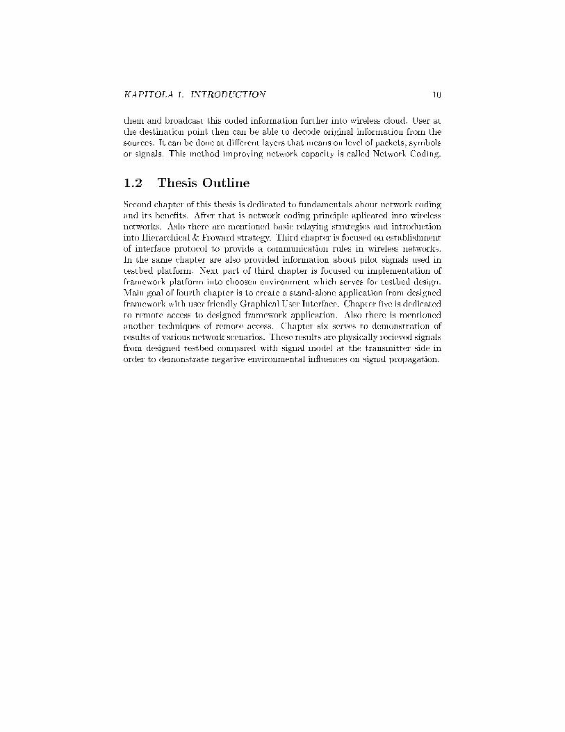
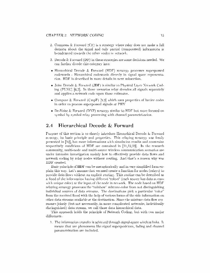
It seems that HDF o�ers signi�cant advantage, because HDF signal process-ing is much more complex. In [11] is shown that HDF can o�er a rectangularcapacity region that can exceed beyond the capacity regions of the other strate-gies. This example of capacity regions is shown in �gure 2.4 and the capacityis shown in �gure 2.5. Nevertheless this improvements are done at the expenseof signi�cantly increasing processing complexity. In addition this processingcomplexity grows exponentially with increasing number of devices in network.
CHAPTER 2. NETWORK CODING 18
Figure 2.4: Capacity regions of HDF [13]
Figure 2.5: MAC capacity for HDF [12]

Part II
Practical contribution
19

Chapter 3
Interface protocol and
framework platform
This chapter is focused on de�ning of interface protocol wrapper. It should bedesigned generic enough to serve for di�erent network cloud scenarios used inplatform. Creation of platform itself is desribed in chapter 4. The second goalof this section is choice of enviroment for this platform which provide su�cientcomputing performance to handle all wireless network requirements and alsoadequate conditions for programming part of this platform.
In beginning of this section are fundamentals about wireless network syn-chronization and distribution of synchronization in these networks. There aredescribed related problems and current state-of-art approaches. Next part isdedicated to de�nition of interface protocol that properly addresses multiplecloud stages and provide synchronization preferences. After that is explainedchoice of basic enviroment for platform including possible other solutions forgiven network scheme. In this chapter will be also provided implementation ofeach approaches of transmission routines with further informations and results.
3.1 Current state-of-art network synchronization
in wireless networks
Synchronization is very important in every network. In general is main tar-get of network synchronization equal distribution of time and frequency to alldevices in network. Synchronization also de�ne symbol timing and distinguishdata from a additive signals used for signalisation. It is necessary for propercommunication especially from receiver point of view.
In wireless networks time and frequency synchronization also serves for aschedule of multiple access to a shared wireless medium. Generally is everydevice in network equiped with its own local oscilator that generates periodicsignals. But these oscillators have limited stability and accuracy which cause
20

CHAPTER 3. INTERFACE PROTOCOL AND FRAMEWORK PLATFORM21
that every oscillator have a slightly di�erent properties. It is commonly given bymanufacture processes and temperature conditions. Therefore is necessary tocoordinate all these oscillators for establishment of common frequency reference.
In wireless network are two basic approaches how to establish and distributefrequency reference.
1. Master-slave (MS) solution is based on hierarchical principle when everynetwork or subnetwork has a node with precise reference clock (masternode). The master node stays at the top of hierarchical topology and allother nodes belonging to a lower priority just adjust their local preciseclocks.
2. Mutually coupled (MC) network synchronization is based on peer-to-peerarranged nodes, where each node controls its local clock with the infor-mation received from all its neighbours.
To introduce basic de�nitions about synchronization regimes, let's consider asimple harmonic oscillator with output
x(t) = A(t) sin(ωt+ φ) (3.1)
where φ is the oscillator phase at t = 0 in radians, f is frequency of the oscillatorand t is absolute time. In this case we can neglect amplitude scaling A(t) = Abecause it has no in�uence on frequency or phase. Then we can claim thatphase of generated signal increments with a speed proportional to the oscillatorfrequency in rad/s ω, dΘ(t)/dt = 2πf . Local time function associated with x(t)is then
τ(t) =f
f0t+
φ
2πf0(3.2)
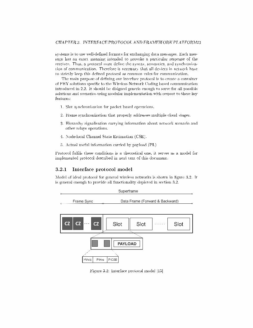
where f0 is the nominal frequency of the oscillator. Actual frequency is alwaysdi�erent from the nominal one f 6= f0 . It is given by heating, manufacturingprocesses or environmental in�ueces. Due to these circumstances following threepossible synchronization scenarios depicted in 3.1 can occur for couple of localclocks τ1(t), τ2(t) .

CHAPTER 3. INTERFACE PROTOCOL AND FRAMEWORK PLATFORM22
Figure 3.1: Di�erent synchronization scenarios [15]
1. Asynchronous mode: clocks run indenpendently with di�erent phases β1 6=β2 and frequencies f1 6= f2.
2. Frequency synchronization: clocks run at the same frequency f1 but withdi�erent phases β1 6= β2
3. Frequency and phase synchronization: phase synchronized clocks naturallyimplies frequency synchronization.
Most wireless communication systems in operation is based on centralised net-work structure, whereby access point (AP) manages the nodes that are within itstransmission range. Therefore AP serves as a master node and provide naturalreference for synchronization processes. In cellular based systems is necessaryfrequency synchronization bacause of handovers. After that could be done car-rier frequency o�set estimate (CFO) at each nodes from APs preamble. Thetime synchronization is necessary whenever medium access is organized intotime slots - TDMA based communications.
The limited accuracy and stability of real oscillators have a very bad impacton transmitted signal. It's caused by di�erence between nominal and actual fre-quency of transmitter which leads to relevant signal distortion. Therefore is oneof the main tasks of synchronization in nowadays wireless networks compensatecarrier frequency.
3.2 Interface protocol
In digital communications generally protocol is a system of rules for data ex-change between devices in network. Main purpose of protocol in communication
CHAPTER 3. INTERFACE PROTOCOL AND FRAMEWORK PLATFORM23
systems is to use well-de�ned formats for exchanging data messages. Each mes-sage has an exact meaning intended to provoke a particular response of thereceiver. Thus, a protocol must de�ne the syntax, semantics, and synchroniza-tion of communication. Therefore is necessary that all devices in network haveto strictly keep this de�ned protocol as common rules for communication.
The main purpose of de�ning our interface protocol is to create a containerof PHY solutions speci�c to the Wireless Network Coding based communicationintroduced in 2.2. It should be disigned generic enough to serve for all possiblesolutions and scenarios using modular implementation with respect to these keyfeatures:
1. Slot synchronization for packet based operations.
2. Frame synchronization that properly addresses multiple cloud stages.
3. Hierarchy signalisation carrying information about network scenario andother relays operations.
4. Node-local Channel State Estimation (CSE).
5. Actual useful information carried by payload (PL)
Protocol ful�ls these conditions is a theoretical one, it serves as a model forimplemented protocol described in next text of this document.
3.2.1 Interface protocol model
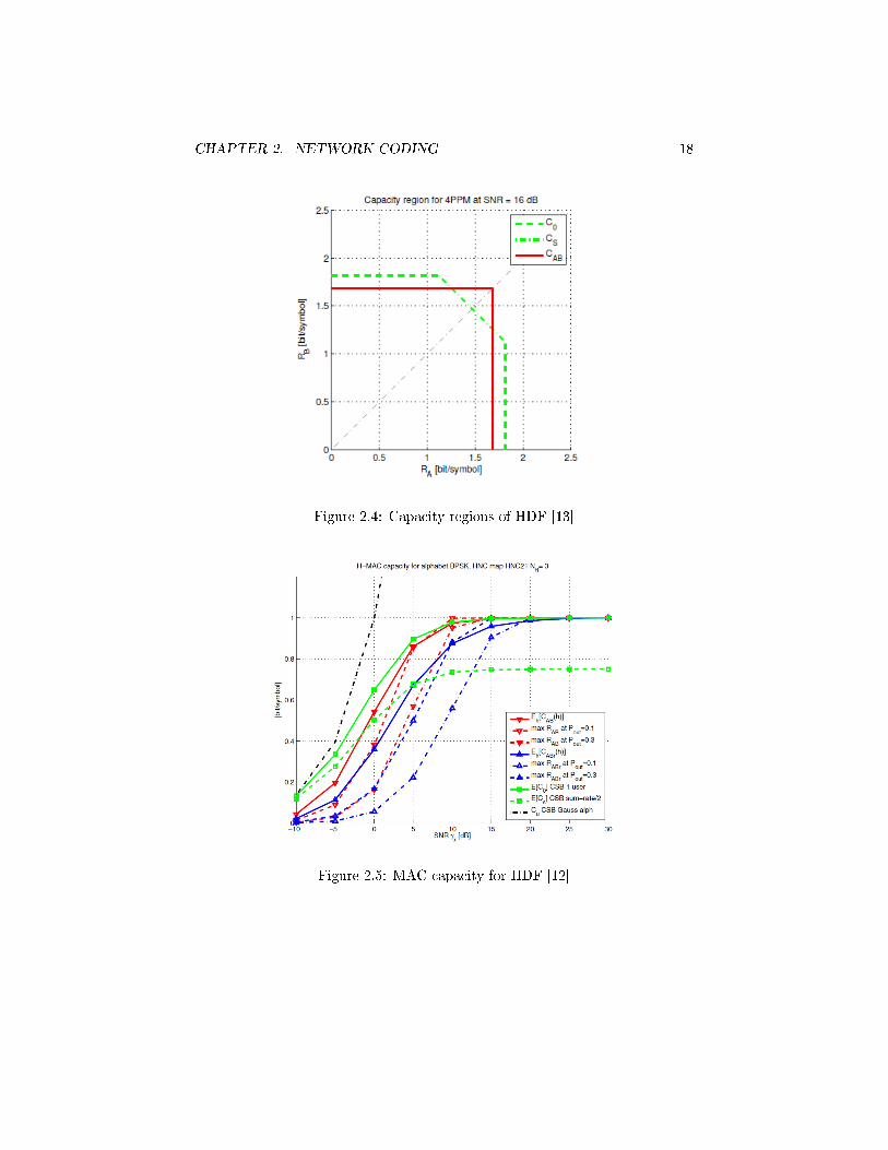
Model of ideal protocol for general wireless networks is shown in �gure 3.2. Itis general enough to provide all functionality depicted in section 3.2.
Figure 3.2: Interface protocol model [15]

CHAPTER 3. INTERFACE PROTOCOL AND FRAMEWORK PLATFORM24
Structure of ideal protocol can be diveded into two main parts. First partis signalisation of superframe start consists of number of unmodulated symbols.This part is called frame synchronization, and for this task are recommended by[15] CAZAC sequences due to its properties. The second part consists of pilotsignals and modulated data symbols. From this point of view synchronizationsection and payload can be assumed as two separated entities.
Very important part of this model are pilot signals. These pilots should bedesigned in such a way to enable all synchronization and signalisation neededfor WPNC PHY layer processing. Separation procedure of pilot signals frompayload have to be generally done without payload codeword decoding process,which should be realized only at the �nal destination. This property is speci�cto WPNC. Reliable pilots must use enough �energy� to provide its function evenin condition which doesn't guarantee correct payload codeword decoding, butsignalisation must be provided.
Acquisition Pilot (PiAcq)
This pilot serves for identi�cation of the node's activity. It means that everynode have to have assigned unique �signature� in form of PiAcq. The secondpurpose of PiAcq is synchronization of slots/packets which corresponds to thetransmitters activity stage slot. In other words slot synchronization means thealignment of the packet inside the slot.
Hierarchy Pilot (PiHrc)
This pilot should provide signalistation of graph fragments of predecessor nodes,in case of more advance network scenarios, directly at PHY layer. It should con-tain information about hierarchical functions of the node itself and all precedingnodes as well as information about network topology. This feature is necessaryfor more complex wireless networks. It also should provide information aboutrelay operations and ID of HNC map. This pilot signal is very speci�c to HDFrelaying strategy.
Channel State Estimation Pilot (PiCSE)
PiCSE should serve for node-local CSI estimator. However in case of multisourcesetup there will be channel parametrisation with higher complexity. The WPNCdecoding processes are strongly dependent on the relative channel coe�cients.Therefore the CSE pilots must be designed in such a way to be resistant tothe non-orthogonal superposition while still providing a high quality relativechannel fading coe�cient estimates.
3.2.2 Implemented protocol
In this subsection is de�ned interface protocol with respects of desired function-ality. To simplify our situation in this solution of protocol are not consideredhierarchical or CSE pilot signals, because it is beyond scope of this work. We

CHAPTER 3. INTERFACE PROTOCOL AND FRAMEWORK PLATFORM25
can also neglect all stage scheduling processes which arise in advance ad-hocdynamic networks due to a priori known network topology and cloud scenario.In order to simplify situation even more, we can assume frame synchronizationand symbol timing due to synchronous transmitters/receivers respectively. Butthis is not completely correct statement for reasons shown in 3.4.2. We can alsoneglect time of signal propagation due to short distances between Tx/Rx. Sothere is no need of any timing advance based methods.
Functionality of interface protocol like this should be su�cient enough toprovide communication in wireless network scenarios used in this frameworkwith respect to half-duplex constraint. The structure of frame for this frameworkis shown in �gure 3.3.
Figure 3.3: Designed frame structure
It can be seen, that beginning of each superframe is signalised with FrameSync pilot signals, for this particular case were choosen CAZAC codes. Eachnode in the network has given unique CAZAC sequence, which is known byall other network's nodes. CAZAC codes are thoroughly described in section3.3. For packet signalisation can be used CAZAC codes or gold codes in thisframework. Packet contain superposition of unique informations from everytransmitting node. The creation of the payload before modulation or codingprocesses is following:
Algoritmus 3.1 Payload design algorithm
tx1_payload = zeros(symbols_per_packet, superframe_length);for i = 0:superframe_length-1
tx1_payload(:,i+1) =data_input_Tx1((i-1)*symbols_per_packet+1:i*symbols_per_packet)];
endend

CHAPTER 3. INTERFACE PROTOCOL AND FRAMEWORK PLATFORM26
This unique data inputs are then modulated, interpolated and after that isbeing made complex envelope. General linear modulation can be descripted as
s(t) =∑n
g (dn, σn, t− nTs) =∑n
g (qn, n− Ts) (3.3)
where g is modulation function, dn are data symbols dn ∈{q(i)}Md−1i=0
and σnare inside states of modulator (memory of modulation, state equation σn+1 =
σ (dn, σn) de�ne evolution of modulator in time). In general σn ∈{σ(i)}Mq−1i=0
whereMq is number of modulator states. Ts is symbol period.
Next operation in this process is upsampling of modulated signal. Inputsignal X is upsampled by inserting N − 1 zeros between input samples. Afterthat is needed to �lter upsampled data by a modulation pulse and this datareshape into superframe structure to keep designed protocol rule.
Implementation of these routines is shown in following algorithm.
Algoritmus 3.2 Modulation, upsample and complex envelope implementation
% modulator objectM=tx1_Mod;hMod = modem.qammod(M);
% modulationtx1_symbols = modulate(hMod,tx1_payload);
% interpolationtx1_upsample = upsample(tx1_symbols, samplespersymbol);
% creation of complex envelope divided into two stepsstep1=�lter(REC_�lter,1,tx_upsample_vectorized);tx1_CE = reshape(step1,symbols_per_packet*nSamp/log2(M),SF_length);
Following algorithm shows addition of unmodulated CAZAC sequences to aupsampled generarlly modulated data inputs now in form of complex envelope.The constant k ∈ {0.25, 1} used to mupltiply amplitude of created complexenvelope is standard procedure to improve ability to detect CAZAC sequenceseven in condition with low SNR ratio. This structure now corresponds with�gure 3.3 and this superframe is prepared for transmition.
Algoritmus 3.3 Frame and Packet Sync addition
for i = 0:superframe_length-1if i == 0
Superframe1(:,i+1) = [FrameSync1;k*tx1_CE(:,i+1)];else
Superframe1(:,i+1) = [PacketSync1;k*tx1_CE(:,i+1)];end
end

CHAPTER 3. INTERFACE PROTOCOL AND FRAMEWORK PLATFORM27
3.3 CAZAC codes
This part is focused on CAZAC codes and its properties suitable for purposes offrame and packet sycnhronization. Constant Amplitude Zero Auto-Correlationcode (CAZAC) is complex-valued periodic signal with modulus and out-of-phaseperiodic auto-correlation equal to zero. This code is generated by cyclicallyshifting the basic CAZAC code of a choosen length and as the name of this codeprompts this shifted CAZAC codes are always orthogonal to its base CAZACcode.
CAZAC sequences allow precise estimation of the frame-start position intime and also in frequency domain, which is very convenient for our purpose.CAZAC sequences are de�ned as a samples of a complex exponential functionwich can be seen from following formula
xN,r(n) =
{exp(−j rπn
2
N ) for N even
exp(−j rπn(n+1)N ) for N odd
(3.4)
where xN,r (n) denotes a sequences of length N and root of r. This root haveto be prime number for ability to provide following properties.
1. CAZAC sequences are periodic with period N if N is odd. It is given by
x (n+N) = x(n)
2. Auto correlation function of CAZAC sequence with a cyclically shiftedversion of itself is zero, it is non zero in one and only case when this shiftcorresponds to the cyclic shift (length of the sequence). It can be seen onfollowing �gure 3.4 that CAZAC sequence with r = 13 and N = 127 isthe same sequence like sequence with r = 140 and N = 127.
Figure 3.4: Cross correlation of CAZAC sequence shifted of 1 periode

CHAPTER 3. INTERFACE PROTOCOL AND FRAMEWORK PLATFORM28
3. The cross correlation between two CAZAC sequences with di�erent rootvalues r is always constant 1√
N, see �gure 3.5. On this �gure are two cross
correlation functions. Blue one is convolution of one period of CAZACsequence with itself, where N = 127 and r = 13 . The red one is crosscorrelation between two CAZAC sequences with r1 = 13, r2 = 17 andcommon length N = 127. Note that peak at m = 127 has an amplitudein maximum at |c(m)| = 127.
Figure 3.5: Cross correlation of two CAZAC sequences with di�erent roots
It is worth noticing that CAZAC sequences is also very resistant against noisein�uences. In addition CAZAC sequences have reduced inter-symbol interfer-ence, that helps to avoid of interferences between multiple antennas and it alsolowers peak-to-average power ratio. Due to this properties, CAZAC sequences�nd application in wireless communication systems very soon. For examplethese sequences is used for channel estimation and sycnhronization routines (forinstance preamble signature) in long-term evolution (LTE) of 3rd GenerationPartnership Project (3GPP). In this framework CAZAC sequences serve forframe and packet synchronization.
3.4 Framework platform
This section is focused on options of possible development environment for thisframework platform design. Choosen development tool have to provide comfort-able enviroment to satisfy demands on this framework. It means that designerof this framework should be able to build this testbed in such a way to ful�lfunctionality described in section 3.2.1 and also to provide adequate enviromentfor implementation of interface protocol (included design of pilot signals) with

CHAPTER 3. INTERFACE PROTOCOL AND FRAMEWORK PLATFORM29
ability to expand this framework to a more complex application. Namely abilityto build user friendy graphical user interface to control whole framework andexpand this framework for instance to another application with remote accessif possible. After considering all of these features there only two meaningfuloptions left.
1. GNU radio is open-source software development toolkit that providessignal processing blocks to implement software radios. It provide opti-mized enviroment for management of Universal Software Radio Periph-eral (USRP) for Tx/Rx in wireless network cloud scenarios. It also allowsto use external high-accuracy timing reference and distribution system(OctoClock-G) for USRPs to ful�l condition of precise frame synchroniza-tion and symbol timing in multi node cloud scenarios. On the other handGNU radio is open-source development toolkit with lack of o�cial supportor documentation.
2. MATLAB is a high-level language and interactive environment for numer-ical computation, visualization, and programming. Matlab is also idealinstrument for algorithm developement with various forms of additionaltoolboxes (for instance Parallel Computing toolbox, Signal Processing andCommunications toolbox etc.). In addition Matlab allows to create ad-vanced Graphical User Interfaces (GUI) to provide a comfortably and userfriendly solution how to control created applications or scripts.
Despite of no guaranty of frame synchronization or symbol timing was selectedMatlab as a base environment tool to design this framework. It can be problem-atic but in next sections is an e�ort of algorithm developement to provide thissynchronization demand. In this point of view can be choice of GNU radio moreoptimal, but to provide perfect synchronization is necessary to buy another ex-pensive device. So the target of next section is to achieve same functionalitywithout spending another �nancial resources.
Both variants have advantages and disadvantages so the decision about whichenviroment select was very di�cult. The GNU radio provides a better perfor-mance of USRPs control but Matlab allows to expand designed framework toan e�ective GUI based application. In addition there is also possibility to makea web based application in case of Matlab based platform. But this topic isfurther descripted in chapter ??.
3.4.1 Real-time signal processing
Nowadays topology of wireless networks is generally dynamic due to portabledevices which are moving in real-time. This is a huge complication for stagescheduling because time delay caused by signal propagation is constantly chang-ing. This means that receiver in these networks can not operate in its relativeclock time given by a local oscillator, because there is no guaranty of receivingany useful data. The method how to guarantee a recieving proper data sequence

CHAPTER 3. INTERFACE PROTOCOL AND FRAMEWORK PLATFORM30
is based on a pilot signal detector which continously in time bu�ers and com-pares recieved signal with de�ned pilot signal indicating start of transmittedsignal. If pilot detector register a start of transmitted signal it gives an orderto a memory bank to store a de�ned number of incomming samples N . Thisnumber of samples is strictly given by a protocol in current network. Storeddata then represents a useful data message from a transmitter object. The de-coding routines have to start immediately after recieving the last symbol of theusefull message. This routine is not so simple as it seems. The memory imple-mentation allows to read and write simultaneously, but have to be preventeda case when second data frame arrives. It can cause a situation when are cur-rently processing data overwritten by a new data message. This is treated byswitching banks of memory that stores a whole message. When is one bank ofmemory �lled with data, it is switched with the empty one and whole payload isprovided to Digital Signal Processor (DSP) to further processing. The commonapproach how DSP access data in memory from is realized by direct memoryaccess (DMA). Meanwhile is �lled second bank of memory in case of the nextpacket arrieved. This process in simpli�ed form is depicted in �gure 3.6.
Figure 3.6: Real-time signal processing
This approach is called real time signal processing. It does not mean thatprocessing is operated on every data symbol recieved in given time but simplyreal time systems have to guarantee response within a strict time constraintoften this time is re�ered usualy in range from microseconds to miliseconds. Inother words real-time system have to recieve data, process them and return theresult fast enough to a�ect the environment at that time.
CHAPTER 3. INTERFACE PROTOCOL AND FRAMEWORK PLATFORM31
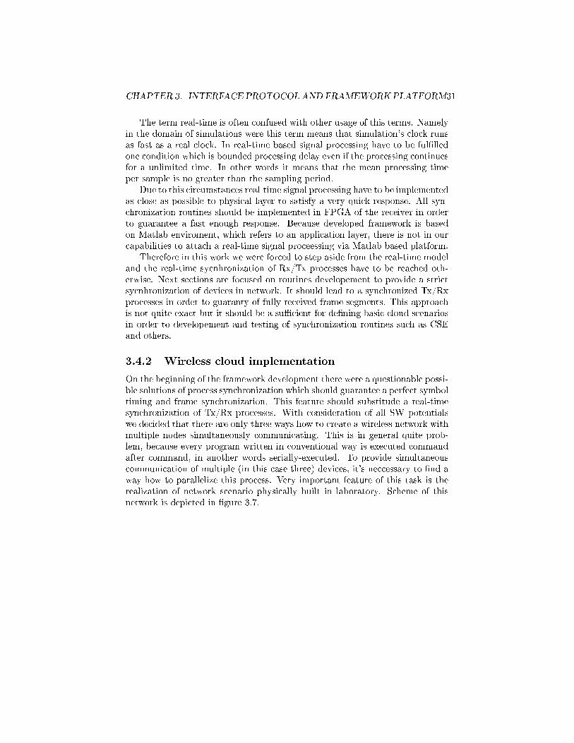
The term real-time is often confused with other usage of this terms. Namelyin the domain of simulations were this term means that simulation's clock runsas fast as a real clock. In real-time based signal processing have to be ful�lledone condition which is bounded processing delay even if the processing continuesfor a unlimited time. In other words it means that the mean processing timeper sample is no greater than the sampling period.
Due to this circumstances real-time signal processing have to be implementedas close as possible to physical layer to satisfy a very quick response. All syn-chronization routines should be implemented in FPGA of the receiver in orderto guarantee a fast enough response. Because developed framework is basedon Matlab enviroment, which refers to an application layer, there is not in ourcapabilities to attach a real-time signal proceessing via Matlab based platform.
Therefore in this work we were forced to step aside from the real-time modeland the real-time sycnhronization of Rx/Tx processes have to be reached oth-erwise. Next sections are focused on routines developement to provide a strictsycnhronization of devices in network. It should lead to a synchronized Tx/Rxprocesses in order to guaranty of fully received frame segments. This approachis not quite exact but it should be a su�cient for de�ning basic cloud scenariosin order to developement and testing of synchronization routines such as CSEand others.
3.4.2 Wireless cloud implementation
On the beginning of the framework development there were a questionable possi-ble solutions of process synchronization which should guarantee a perfect symboltiming and frame synchronization. This feature should substitude a real-timesynchronization of Tx/Rx processes. With consideration of all SW potentialswe decided that there are only three ways how to create a wireless network withmultiple nodes simultaneously communicating. This is in general quite prob-lem, because every program written in conventional way is executed commandafter command, in another words serially-executed. To provide simultaneouscommunication of multiple (in this case three) devices, it's neccessary to �nd away how to parallelize this process. Very important feature of this task is therealization of network scenario physically built in laboratory. Scheme of thisnetwork is depicted in �gure 3.7.

CHAPTER 3. INTERFACE PROTOCOL AND FRAMEWORK PLATFORM32
Figure 3.7: Network scheme
Figure 3.7 shows that communication between PC (with invoked Matlab in-stance) and individual USRPs is via LAN switch, that also causes unpredictablelong delay in the information path. But in mean this delay can be considered asconstant and uniformlly distributed to all USRPs. But in general this networkscheme degrades any synchronization procedures created in application layer.In order to keep precise and time invariant synchronization of multiple devices,it is necessary to implement this process directly on PHY layer. UnfortunatellyMatlab does not provide a coordination of processes by an external precise clocksource. Therefore following sections are focused on approaches how to reach thesame result with curent state-of-art resurces.
There is three general approaches how to ful�l condition of frame synchro-nization and symbol timing for three devices simultaneously in Matlab basedframework platform:
1. Sequential programming: This approach in its nature can never ful�l thecondition of simultaneous control of three devices. The main idea of thisapproach is that time di�erence between two transmitters is given only byone command execution in Matlab. The question is if this method willbe su�cient enough for this framework or if is needed another solutionof device synchronization. Implementation of this approach is thoroughlydescripted in subsection 3.4.3.
2. Parallel Computing: Matlab enviroment includes Parallel Computing Tool-box. This toolbox provide ability to solve computationally and data-intensive problems using multicore processors. This parallelization is de-

CHAPTER 3. INTERFACE PROTOCOL AND FRAMEWORK PLATFORM33
signed to o�er boost in data processes. It is e�ective especialy with arrayoperations and parallelized numerical algorithms. Athough this toolboxis not developed for synchronization of peripheral devices as USRPs, insection 3.4.4 we try to design algorithm in such a way to be able providesynchronnous operational mode of active devices.
3. Invoke multiple Matlab instances: This method can be implemented butit su�ers with lack of frame and symbol synchronization. In basic formof this method is guaranted only simultaneous communication of multi-ple nodes (based on how many instances of matlab are invoked). Thereis possible improvement of this method to satisfy demand of frame syn-chronization and symbol timing by a clock counter routine with higherpriority than matlab instances. If this �clock� allows to send commandto all matlab instances simultaneously, it will provide frame and symboltiming synchronization.
3.4.3 Sequential programming implementation
This approach has very strightforward advantage in form of implementationsimplicity. But on the other hand it su�ers with lack of ability to ful�l a keyrequierement for this framework platform i.e. synchronous Tx/Rx operationalmode. This is crucial disadvantage of this method. The question is if the delaybetween two transmitting processes will be long enough to disable usage ofHNC decoding processes. This inserted delay between transmissions is givenby one command execution in Matlab. Theoretically it can be processed insuch a way, that the machine cycles of matlab will have almost zero impact ofsynchronization error. But this is only theoretical assumption, in reality is thisdelay caused by one machine cycle shown in �gure 3.9.
The instruction �ow chart for this approach of sequential algorithm is de-picted in �gure 3.8.

CHAPTER 3. INTERFACE PROTOCOL AND FRAMEWORK PLATFORM34
Figure 3.8: Instruction chart �ow of sequential algorithm
Implementation of this algorithm into Matlab can be done with di�erentways via di�erent cycles. In algorithm 3.4 is implemented algorithm with cyclewhile which stops after super frame is three times send. This makes a frameworkmore robust and resistible against unpredictable enviroment in�uences.
CHAPTER 3. INTERFACE PROTOCOL AND FRAMEWORK PLATFORM35
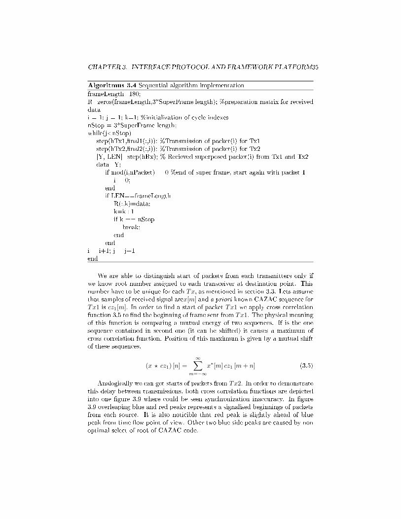
Algoritmus 3.4 Sequential algorithm implementation
frameLength=180;R=zeros(frameLength,3*SuperFrame length); %preparation matrix for receiveddatai = 1; j = 1; k=1; %initialization of cycle indexesnStop = 3*SuperFrame length;while(j<nStop)
step(hTx1,�nal1(:,i)); %Transmission of packet(i) for Tx1step(hTx2,�nal2(:,i)); %Transmission of packet(i) for Tx2[Y, LEN]=step(hRx); % Recieved superposed packet(i) from Tx1 and Tx2data=Y;
if mod(i,nPacket)==0 %end of super frame, start again with packet 1i = 0;
endif LEN==frameLength
R(:,k)=data;k=k+1if k == nStop
break;end
endi = i+1; j = j+1end
We are able to distinguish start of packets from each transmitters only ifwe know root number assigned to each transceiver at destination point. Thisnumber have to be unique for each Tx, as mentioned in section 3.3. Lets assumethat samples of received signal arex[m] and a priori known CAZAC sequence forTx1 is cz1[m]. In order to �nd a start of packet Tx1 we apply cross correlationfunction 3.5 to �nd the beginning of frame sent from Tx1. The physical meaningof this function is comparing a mutual energy of two sequences. If is the onesequence contained in second one (it can be shifted) it causes a maximum ofcross correlation function. Position of this maximum is given by a mutual shiftof these sequences.
(x ? cz1) [n] =
∞∑m=−∞
x∗[m] cz1 [m+ n] (3.5)
Analogically we can get starts of packets from Tx2. In order to demonstratethis delay between transmissions, both cross correlation functions are depictedinto one �gure 3.9 where could be seen synchronization inaccuracy. In �gure3.9 overleaping blue and red peaks represents a signalised beginnings of packetsfrom each source. It is also noticible that red peak is slightly ahead of bluepeak from time �ow point of view. Other two blue side peaks are caused by nonoptimal select of root of CAZAC code.

CHAPTER 3. INTERFACE PROTOCOL AND FRAMEWORK PLATFORM36
Figure 3.9: Synchronization inaccuracy for simultaneous 2Tx-Rx
In order to further analyzation of this time interval between transmissions isprovided zoomed �gure of the same scenario and received signal in �gure 3.10.
Figure 3.10: Zoomed frame synchronization slip
This method is not entirely exact, but has its own advantages. Besides al-ready mentioned implementation simplicity, with this approach can be designedall network cloud scenarios for this framework. The synchronization slip is un-avoidable in this method but is stabile so future designer of synchronization anddecoding routines can involve this delay to his algorithms.
3.4.4 Parallel computing implementation
The days when was main target of processor design its frequency are gone.Multicore processors are the new direction manufacturers are focusing on. Usingmultiple cores on a single chip is advantageous in raw processing performancewith ability to handle more processes simultaneously. This trend lasts over

CHAPTER 3. INTERFACE PROTOCOL AND FRAMEWORK PLATFORM37
�ve years and brings new opportunities and solutions to program designers.And multicore processing is a key feature in this method. We try to use allresources of Matlab enviroment to design algorithm in such a way, to achievesynchronization of all devices used for this task.
Matlab Parallel Computing Toolbox can split execution of program on paral-lel parts using multicore processors. This toolbox let us use the full processingpower of multicore processors by executing applications on workers (Matlabcomputational engines) that run locally.
With this toolbox we can theoretically parallelize two or more (based onnumber of cores of particular PC) by a creating multiple Matlab workers whichshould operate indenpendently of each other. This method is to the eye veryso�sticated and easy to implement. But the parallel routines provided in thistoolbox does not allow to user assign commands to individual cores. This un-ability to allocation of individual processes to workers can be crucial and inworst case it can makes this method unrealizable.
The �rst and most easy way how to discover behaviour of parallelization ofMatlab is to rewrite algorithm 3.4 to a parallel for loop provided by a ParallelComputing Toolbox. Assumption that just a change of loop cycle type forparallel one is very naive, but it is good start point of algorithm developement.The chart �ow of this basic algorithm is shown in the �gure 3.11.
Figure 3.11: Basic parallel algorithm chart �ow
Implementation of this algorithm is basicly the same like algorithm 3.4.During testing procedure of this algorithm error immediately occurs. It wascaused by worker collision on step instruction which reserves a USRP object fora short period of time and multiple workers try to communicate with the sameUSRP. And because there is no rule or authority to avoid this collision, thismethod is impracticable.
One of the routines which should avoid this collision is based on partition of

CHAPTER 3. INTERFACE PROTOCOL AND FRAMEWORK PLATFORM38
transmision routines into individual functions. This can be done by a functionarray, which will be processed within parallel loop. The chart �ow of thisalgorithm is shown in �gure 3.12.
Figure 3.12: Sliced parallel algorithm for collision avoidance
This algorithm in its nature does not provide a fully synchronization ofprocesses but only parallelization of transmission routines. But it is only wayhow to check if the routine for allocating workers for each called function isworking or not. It was done by replacing step functions by an easy displayfunctions. It was proven that each cycle there were three displayed messagesin matlab workspace. After this testing phase was algorithm implementd inMatlab as shows following algorithm.

CHAPTER 3. INTERFACE PROTOCOL AND FRAMEWORK PLATFORM39
Algoritmus 3.5 Sliced parallel algorithm
matlabpool (number_of_devices);funList=(@func1,@func2,@func3);i=1;j=1;k=1;
while(j<nStop)parfor l=1:length(funList)
funList{l}(�nal1,�nal2,hTx1,hTx2,hRx);end
if mod(i,nPacket)==0i = 0;
enddata=Y;
if LEN==frameLengthR(:,k)=data;k=k+1
endi=i+1,j=j+1,k=k+1;
end% example of func1function func1(�nal1,~,hTx1,~)step(hTx1,�nal1(:,i));end
We have to send variables and objects to every function as an argumentsbecause called functions have a independent workspaces. Unfortunatelly thisalgorithm has a one crucial problem i.e. initialization of USRPs every loop cy-cle which causes ridiculously long delay between each cycle. This can be solveby creation of the same loops within the each function. But anyway this par-allelization also does not guarantee an sycnhronization of the parallel cycles.These features should be treated in next algorithm adjustment. The lack ofsynchronization of these parallel loops will be treated by a barrier routine. Be-cause we cant use a Matlab barrier routine provided by a spmd function in formof labBarrier command, we have to �nd out another solution of parallel taskssycnhronization. For this purpose is used a semaphore routine. Semaphore isprogram written in C to provide semaphore routine in Matlab enviroment bycompiling this C program into a MEX �le. This semaphore works on rela-tive easy principle and manipulation with semaphore is similar to function. Infollowing algorithm will be described semaphore functionality.

CHAPTER 3. INTERFACE PROTOCOL AND FRAMEWORK PLATFORM40
Algoritmus 3.6 Semaphore functionality
semaphore('create',uniquekey,init_value)% for example uniquekey=3; init_value=2;
semaphore('wait',uniquekey)% init value decremented by one
semaphore('wait',uniquekey)% init value decremented by one (0 - locked)
semaphore('post',uniquekey)% init value incremented by one
semaphore('post',uniquekey)% init value incremented by one - unlolck processes
The algorithm char�ow with used semaphores to synchronize all transmissionroutines is depicted in following �gure 3.13.
Figure 3.13: Parallel algorithm with semaphores
This algorithm have to use extra one loop to control semaphores whichare used to create a barrier right before each step function. Therefore is keyfeature of this algorithm barrier function which create a barrier for the �rstthree workers accessed this function till the forth one unlocks all these workersat once. Implemented barrier function is shown in following algorithm 3.7.

CHAPTER 3. INTERFACE PROTOCOL AND FRAMEWORK PLATFORM41
Algoritmus 3.7 Barrier function
function barrier()semaphore('wait', cntMutexKey); % separation of parallel tasksbarrierCnt = barrierCnt + 1;if(barrierCnt == 4) %We now know that func1,func2,func3 are waitingbarrierCnt = 0; %reset countsemaphore('post', cntMutexKey);semaphore('post', barrierKey); %Increment barrier count, so a func will
run.semaphore('post', barrierKey); %Increment barrier count, so a func will
run.semaphore('post', barrierKey); %Increment barrier count, so a func will
run.elsesemaphore('post', cntMutexKey);semaphore('wait', barrierKey); %Wait for other threads (this is a barrier).
endend
Unfortunatelly this algorithm isn't realizable due to unability to set a counterof barrierCnt. It is necessary to pass this variable via an argument to thisfunction so every worker who access this function sets this variable again to value1. Therefore is necessary to �nd another solution then via parfor loop. Thisfunctionality could be provided via function spmd wich allows to execute thebody of this function in parallel. In addition it should provide more sophisticatedallocating of tasks to each worker. In following algorithm we divide workers byspecial labindex command which is provided by function spmd. This indexrefers to a unique number of parallel worker created in Matlab. Therefore itis very convenient tool how to separate tasks via switch-case nesting function.At top of that, the body of spmd can work with base workspace therefore isno need to passing variables via arguments. The following algorithm representsimplementation into Matlab.

CHAPTER 3. INTERFACE PROTOCOL AND FRAMEWORK PLATFORM42
Algoritmus 3.8 Adjusted parallel algorithm with barrier
barrierKey = 4; % initialize value of barrier semaphoresemaphore('create', barrierKey, 3); % has count of 3 (devices) +1 to controllsemaphore('wait', barrierKey); % 2semaphore('wait', barrierKey); % 1semaphore('wait', barrierKey); % now it has 0 (next 'wait' is barrier)matlabpool(4)spmdswitch (labindex)case 1while(j<nStop)semaphore('wait', barrierKey)step(hTx1,�nal1(:,i));if mod(i,nPacket)==0i = 0;
endi = i+1;j = j+1;
endcase 2while(j<nStop)semaphore('wait', barrierKey)step(hTx2,�nal2(:,i));if mod(i,nPacket)==0i = 0;
endi = i+1;j = j+1;
endcase 3while(j<nStop)semaphore('wait', barrierKey)[Y, LEN]=step(hRx1);data=Y;if LEN==frameLengthR(:,k)=data;k=k+1; j = j+1;
endend
case 4while(j<nStop)pause(0.1) % protection interval other workers should wait on barriersemaphore('post', barrierKey)semaphore('post', barrierKey)semaphore('post', barrierKey) % unlocks the USRPsj=j+1;end
labBarrier;end

CHAPTER 3. INTERFACE PROTOCOL AND FRAMEWORK PLATFORM43
During testing of this algorithm several errors occurs randomly. It meansthat sometimes transmitting process of two transceivers pass without any errorsbut usualy an error occured. In cases when error occurs, it was due to unabilityof Matlab to provide data for USRPs and in couple of cases again due to anunability to reach USRP in particular time of error. The cause of this behaviourmay be the fact, that in spite of three/four matlab parallel workers were created,it does not guarantee an physical allocating of processor cores to each worker.This schedulling is strictly in control of OS scheduler.
The error where is not supported data for ettus had a key part �requestednumber of samples. Expected 3597, Found 0� that can be caused by two features.The �rst one is the unability of Matlab to give a high amount of data to allUSRPs at once. But it is highly unlikely. Therefore we were also testing the samealgorithm with half packet length and after that with quarter of packet length.But the result was be the same. The second variant can be limitation of currentstate-of-art network scheme depicted in �gure 3.7 because it could be causedby a limitation from an IP packet structure, where is the MTU (MaximumTransmission Unit) for Ethernet de�ned as 1500 bytes per instance. That couldbe solved by a workstation equipped with three ethernet cards directly connectedto each USRP.
3.4.5 Multiple Matlab sessions
This approach is based on invoking multiple Matlab sessions. The transmissionroutines are wholly independent and in this approach is guaranted avoidanceof Matlab collision in communication with USRP. The principal scheme of thisapproach is depicted in �gure 3.14.
Figure 3.14: Multiple Matlab sessions
The huge disadvantage of this method is lack of any sycnhronization of these

CHAPTER 3. INTERFACE PROTOCOL AND FRAMEWORK PLATFORM44
processes. Therefore is no guaranty of recieving an usefull data. But it can becompensated by a very long cycle where is multiple times transmitted the samesuperframe. This method is realizable but not optimal one.
Due to these circumstances the frame synchronization and symbol timingseems to be unrealizable via the Matlab platform. However, the sequential al-gorithm were not provide so bad results and therefore is the framework platformbased on this algorithm. It is su�cient enough to provide tool for a design ofsynchronization algorithms and other experiments.

Chapter 4
Framework implementation
with GUI
Main goal of this chapter is to develope a Graphical User Interface (GUI) forframework. We will descibe two basic approaches how to buit GUI in Matlabwith examples. We also try to mention basic Matlab graphical control units anddescribe hierarchy of Matlab graphical structure. This hierarchical structure iskey factor for understand data �ows between multiple GUIs and scripts. Finalproduct of this chapter should be creation of stand-alone application whichprovide full functionality and also brings portability of this framework to anotherdevices. In addition, functionality of this application will sustain even on deviceswithout Matlab installation. This fact had relevant role during decision makingabout suitable platform for this framework.
When is program used by a several persons the raw script is can be confusingfor those which have knowledge about used language.
4.1 Approaches of GUI development
A graphical objects were already mentioned but these objects weren't de�nedyet. Graphical object is every basic elements used for displaying any kind ofgraphical output. For clearly understanding core of this topic is very importantto know mutual organization and subordination of these objects - hierarchy.Matlab graphical objects hierarchy is shown in following picture4.1 and is veryimportant for data management in more advanced GUIs.
45

CHAPTER 4. FRAMEWORK IMPLEMENTATION WITH GUI 46
Figure 4.1: Hierarchy of basic graphical objects of Matlab system
A Matlab GUI is a �gure window to which designer can add user-operatedgraphical components. Designer of GUI have to select type, size and positionof graphical components as he likes, but generaly it should be designed in sucha way to provide well-arranged tool for end users. The functionality of anygraphical component is given by a property called Callback. Using callbacksallows the components do its function by only clicking on that object.
System Handle Graphics was implemented to Matlab to provide a e�ectivecontrol of all graphical objects. The main feature of Handle Graphic system isa unique number assigned to every graphical object in Matlab.
In �gure 4.1 is depicted objects hierarchy and if some graphical object iscreated then is uniquely determined by a handle value. Except of the tobjectRoot at a top of hierarchy which has strictly given handle value 0. For examplewe create a new graphical object �gure by a command h=�gure and the following�gure object appears.
Figure 4.2: Figure object example
CHAPTER 4. FRAMEWORK IMPLEMENTATION WITH GUI 47
By command h=�gure was unique handle number assigned to variable hwich helps with further work with �gure. Now we can check value of variable hand the result is h = 1. In other words Handle of object Figure in this case isnumber 1. We can imagine �gure object like a window with some name (Figure1) which is ready to de�ne underling graphical objects (Uicontrol, Uimenu,Uicontexmenu) in Matlab hierarchy depicted in �gure 4.1.
Another important feature of GUI is a fact that every GUI has its ownworkspace independent of other worskpaces where are stored variables and ob-jects in form of local variables. For instance if we declare variable or objectin GUI, these objects are invisible to Matlab's base workspace and vice versa.This feature brings several obstacles which will be described in following text.
There are only two basic approaches of developing GUI in Matlab:
1. Programmatic GUI construction: created code �les generates GUIs as afunctions or scripts.
2. GUIDE (GUI Developement Enviroment): is an interactive GUI constuc-tion kit.
The code �les of these two approaches look di�erent. Programatic GUI �les aregenerally longer, because they explicitly de�ne every property of the �gure andits controls (position, visibility, name, etc.), as well as the callbacks for theseobjects. GUIDE GUIs de�ne most of the properties of objects within the �gureitself. All these properties are stored in its FIG-�le instead of directly in itscode �le. The code �le then contains only callbacks and other functions thatinitialize the GUI when it opens. If is GUI builded via GUIDE there is possibilityto modify it programmatically. However GUI created programmatically can notbe then modi�ed with GUIDE. Ways how to build a GUI is shown in followingtext.
4.1.1 Programmatic GUI construction
Using this approach, designer creates a code �le that de�nes all component prop-erties and behaviors. When a user executes the �le, it creates a �gure, populatesit with components, and handles user interactions. It can be demonstrated onfollowing example where will be created a main menu similar to main menu offramework created later in this work. It can be done by following algorithm.

CHAPTER 4. FRAMEWORK IMPLEMENTATION WITH GUI 48
Algoritmus 4.1 Programmatic main menu example
function example()% initialization part
f = �gure('Visible','o�','Position',[360,500,450,285]);hcloud = uicontrol('Parent',f,'Style','pushbutton','String','Cloud',...'Visible','on', 'Position',[170,220,80,25]);
hTx = uicontrol('Parent',f,'Style','pushbutton','String',...'Transceivers','Position',[170,190,80,25]);
hsync = uicontrol('Parent',f,'Style','pushbutton',...'String','Sync','Position',[170,160,80,25]);
hR_strat = uicontrol('Parent',f,'Style','pushbutton',...'String','Relay Strategy', 'Position',[170,130,80,25]);
hrelay = uicontrol('Parent',f,'Style','pushbutton',...'String','Relay', 'Position',[170,100,80,25]);
hreceiver = uicontrol('Parent',f,'Style','pushbutton',...'String','Receiver','Position',[170,70,80,25]);
hSim = uicontrol('Parent',f,'Style','pushbutton','String','Simulation', ...'Position',[170,40,80,25]);
align([hcloud,hTx,hsync,hR_strat,hrelay,hreceiver,hSim],'Center','None');% Make the GUI visible.
set(f,'Visible','on') end
This code creates a �gure with default uicontextmenu and uimenu and sev-eral pushbuttons as shows �gure 4.3.
Figure 4.3: Raw main menu example
This GUI has no functionality yet because there are no callback functionsde�ned. Also name is default and objects uimenu and uicontextmenu are ir-relevant here. Next algorithm provide change name of �gure, de�ne callbackfunction of Cloud pushbutton and also hide uimenu and uicontextmenu.

CHAPTER 4. FRAMEWORK IMPLEMENTATION WITH GUI 49
Algoritmus 4.2 Callback function and adjustment of �gure
% uimenu and ui contextmenu removalset(f,'Name','Main menu','MenuBar','none');
% de�nition of callback function to object propertyset(hcloud,'Callback',{@cloudbutton_Callback});
% execution of callback functionfunction cloudbutton_Callback(source,eventdata)
f2=�gure('Visible','on','Position',[800,400,600,600], ...'MenuBar','none','Name','Cloud');
end
The Cloud pushbutton callback function was de�ned to invoke another �gureobject. Demonstration result of GUI and pushbutton behaviour with invokedsecond �gure object is shown in �gure 4.4.
Figure 4.4: Callback function execution and �gure adjustment
This is simple demonstration of programmatic GUI developement in Matlab.Advantage is that designer de�ne only properties and callback function whichis necessary for desired functionality of GUI, but on the other hand, in morecomplicated and advanced GUIs with multiple windows, created codes is verylarge. Due to this feature orieantation in this code is then more di�cult. Henceis prefered way to build a GUI with using GUIDE.
4.1.2 Graphical user interface development environment
Matlab have a tool designed especially for developement of GUIs and it is calledGUIDE. Key feature of GUIDE is a graphic layout editor, where is created �gureand a source code is then automaticly generated.
This approach starts with a �gure that can be populated with componentsfrom within a graphic layout editor. GUIDE creates an associated raw sourcecode �le containing callback functions for the GUI and its components. GUIDEsaves both the �gure (as a FIG-�le) and the code �le. Opening either one alsoopens the other to run the GUI. Navigation in this approach is very easy, only byclicking in layout editor on desired graphical object, it redirects on the callback
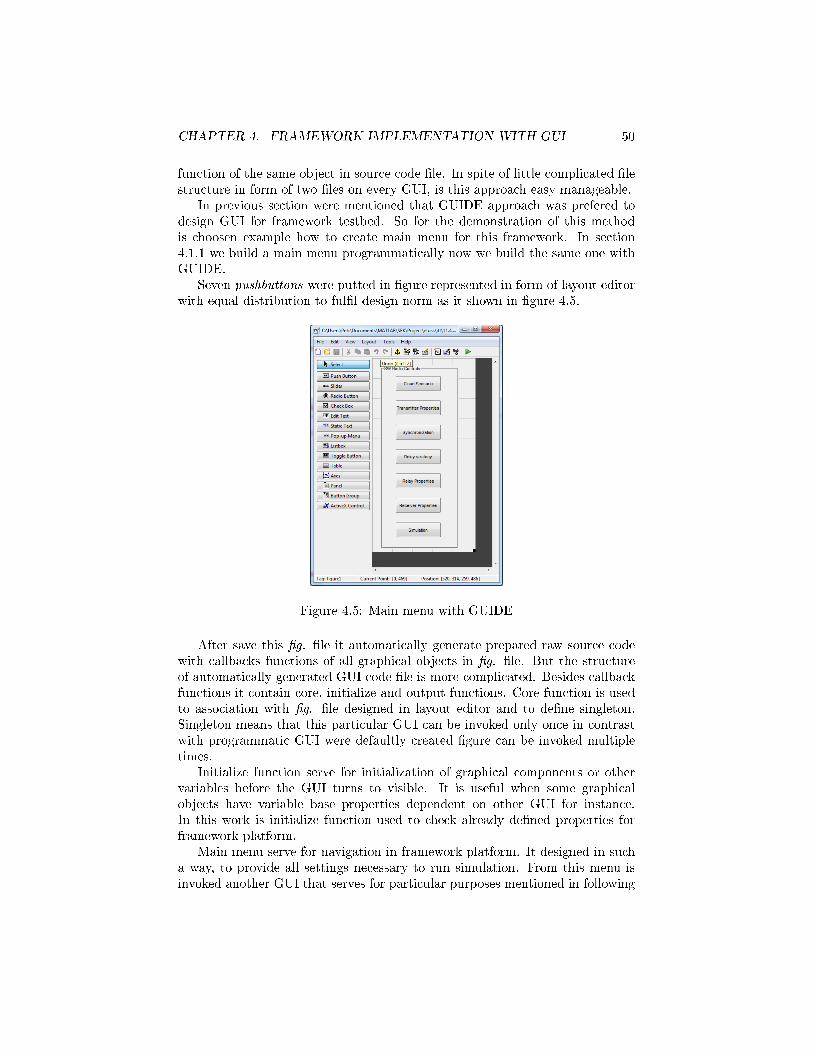
CHAPTER 4. FRAMEWORK IMPLEMENTATION WITH GUI 50
function of the same object in source code �le. In spite of little complicated �lestructure in form of two �les on every GUI, is this approach easy manageable.
In previous section were mentioned that GUIDE approach was prefered todesign GUI for framework testbed. So for the demonstration of this methodis choosen example how to create main menu for this framework. In section4.1.1 we build a main menu programmatically now we build the same one withGUIDE.
Seven pushbuttons were putted in �gure represented in form of layout editorwith equal distribution to ful�l design norm as it shown in �gure 4.5.
Figure 4.5: Main menu with GUIDE
After save this �g. �le it automatically generate prepared raw source codewith callbacks functions of all graphical objects in �g. �le. But the structureof automatically generated GUI code �le is more complicated. Besides callbackfunctions it contain core, initialize and output functions. Core function is usedto association with �g. �le designed in layout editor and to de�ne singleton.Singleton means that this particular GUI can be invoked only once in contrastwith programmatic GUI were defaultly created �gure can be invoked multipletimes.
Initialize function serve for initialization of graphical components or othervariables before the GUI turns to visible. It is useful when some graphicalobjects have variable base properties dependent on other GUI for instance.In this work is initialize function used to check already de�ned properties forframework platform.
Main menu serve for navigation in framework platform. It designed in sucha way, to provide all settings necessary to run simulation. From this menu isinvoked another GUI that serves for particular purposes mentioned in following

CHAPTER 4. FRAMEWORK IMPLEMENTATION WITH GUI 51
sections. Algorithm 4.3. shows implementation of callback function generatedby GUIDE. This function opens another GUI namely Cloud GUI which provideselection of desired cloud scenario.
Algoritmus 4.3 Callback function in GUIDE
% � Executes on button press in pushbutton_mm_cloud_scenario.function pushbutton_mm_cloud_scenario_Callback(hObject, eventdata,
handles)% hObject handle to pushbutton_mm_cloud_scenario (see GCBO)% eventdata reserved - to be de�ned in a future version of MATLAB% handles structure with handles and user data (see GUIDATA)
Cloud; %Calling GUI Cloud
4.2 Framework GUI
In previous section was designed main menu of this framework platform. Thismenu serves for coordination of all GUIs created and to store data from theseGUIs. In other words main menu in this platform only invokes other GUIs whichserve for particular function. But main menu in this case has no in�uences onthe �nal simulation. Framework simpli�ed structure with data �ows betweenindividual GUIs is shown in following picture 4.6 .
Figure 4.6: Framework GUI core structure with data �ows
This framework is designed in such a way that user have a various optionshow to con�gure his desired wireless network cloud.

CHAPTER 4. FRAMEWORK IMPLEMENTATION WITH GUI 52
It provide:
• Variable wireless network scenarios.
• Variable Tx properties (gain, frequency, o�set, etc) included variable pay-load for transmission.
• Adjustable SuperFrame structure namely lenght of packets or SuperFramelength.
• User can select one of two supported modulations and also one of the twomodulation pulses.
• Relaying strategies
• Adjustable relay properties included �le name of recieved signal to besaved.
• Variable Rx properties
• User can select and choose various synchronization options.
4.2.1 Data management in multiwindow GUI
The main issue of data management between individual GUIs is the fact thatevery GUI has its own workspace where are stored variables and objects in aform of local variables. This makes a data sharing a little bit complicated.There are two approaches how to store data from GUI and after then load thisdata in another GUI.
1. Via guidata(hObject,handles): This method is based on handle structureof GUI. The main disadvantage of this way of storing data is a abilityto managa only one variable at any time because another call guidata(hObject,handles) overwrites the previously created version of GUI data.Therefore is this variant higly non optimal and is not implemented in anypart of GUI.
2. Via setappdata(h,name,value): Setappdata stores values of val in a GUIinto a handle of a component h. The string of charakters name (secondargument in ' ') is name for the data. Stored data in this way are uniquellyidenti�ed. The value of h identify data location and name identify a nameof variable with stored value val. This data can be retrieved any time byusing command getappdata(h,'name'). This method of data managementin GUI is much more straightforward and is globally recommended for GUIimplementation. In this work are all variables obtained from edit_textboxes or pop_up menus stored in this way.

CHAPTER 4. FRAMEWORK IMPLEMENTATION WITH GUI 53
4.2.2 Network Cloud Scenario GUI
This GUI serves to de�nition of desired scenario. User can arbitrarily selecttopology as he likes but there is constrain in form of limited number of USRPs.Available are three USRPs devices which can be used either like transmitter orlike receiver. This is caused because of half-duplex constraint. Cloud scenarioGUI design is depicted in �gure 4.7.
Figure 4.7: Cloud scenario GUI
Figure 4.7 represents a selected scenario with two transmitters and one re-lay. This GUI is designed with respect to a limited number of devices. Whenuser selects third device, other selections are disabled and can be released byunchecking of the last selected item. Algorithm 4.4 shows how is this routineimplemented in Matlab. Principle of this algorithm is implemented in check-boxes callback functions as well but with di�erent device enabled as the lastone. The �nal function of this GUI is to store the number and type of selecteddevices, to provide initialize functions of other GUI. When the user select cancelbutton, the GUI is simply closed without stored any data and can be invokedagain later.

CHAPTER 4. FRAMEWORK IMPLEMENTATION WITH GUI 54
Algoritmus 4.4 Cloud scenario de�nition
function checkbox_Tx1_Callback(hObject, eventdata, handles)global deviceif (get(hObject,'Value') == get(hObject,'Max'))% Checkbox is checked-take appropriate actiondevice=device+1;
if device == 3set(handles.checkbox_cloud_tx2,'Enable','o�')
**Analogically the rest is disabledelseset(handles.checkbox_cloud_tx2,'Enable','on')**Analogically the rest is enabledendelsedevice=device-1;set(handles.checkbox_cloud_tx1,'Enable','on')**Analogically the rest is enabledend
4.2.3 Transmitter Settings GUI
In this GUI is very important initializing function, which serves to de�ne pop-up menus string properties. This string is given by result of �ndsdru functionwhich searches for available USRPs in LAN and provide list of IP addresses ofavailable devices. Implementation of initializing function in Matlab is describedin algorithm 4.5. This function provide list of all available USRP devices toboth pop-up menus of this GUI.
Algoritmus 4.5 Initializing function in GUI
function transmitters GUI_OpeningFcn(hObject, eventdata, handles, varargin)set(gcf,'Name','Transmitter settings');global IPIP=�ndsdru;for i=1:length(IP)address{i} = IP.IPAddress;endaddress{length(IP.USRPs)+1}='none';set(handles.popupmenu_tx_sdru1,'String',address);set(handles.popupmenu_tx_sdru2,'String',address);
Next function of this GUI is ability to call another GUIs to de�ne datasegments, transmitter properties and super frame options. Structure of thisGUI is depicted in �gure 4.8.

CHAPTER 4. FRAMEWORK IMPLEMENTATION WITH GUI 55
Figure 4.8: Transmitter settings GUI structure
Transmitter settings GUI is designed in such a way to provide explicit de�-nition of IP addresses of USRPs to create transmitter object. It also provide aoptions to set transmitter properties, superframe properties and data containedin payload of each transmitter device. Design of this GUI is depicted in �gure4.9 where is demonstrated a function of previously created Cloud Scenario GUI.In this case was selected in Cloud Scenarion GUI only one transmitter, thereforeis here enabled to modify only one transmitter object as well.
Figure 4.9: Transmitter settings GUI
Transmitter Data GUI This GUI is one of four GUIs that could be invokedby Transmitter settings GUI. The main function of this GUI is to de�ne datato payload of transmitter. Design of this GUI is the same for both transmittersbut the data inputs are entirelly separated and independent. This GUI is shownin �gure 4.10. Data GUI allows to choose data inputs. It could be one of fol-lowing options: black and white picture, random data, text message or alreadymodulated signal.
Transmitter Properties GUI This GUI allows to de�ne speci�c propertiesof each transmitter (i.e. center frequency, gain, interpolation factor, etc.) andalso modulation pulse and modulation. But for safe program run is recom-mended to use a default properties due to a gain variable. Wrong gain value

CHAPTER 4. FRAMEWORK IMPLEMENTATION WITH GUI 56
can destroy expensive USRP devices. However this possibility is treated by lim-itation of gain value programatically. All properties that could be change aredepicted in �gure.
Super frame settings GUI The last GUI that could be called from Trans-mitter settings GUI allows to modify structure of super frame. Design of thisGUI is very simple and is depicted in �gure 4.10. It is worth to notice that num-ber of packet value is valid only for random data input. In order to guaranteethat all data will be contained in a one superframe it is necessary to adapt thisvalue to size of data input.
Figure 4.10: Transmitter Data GUI: a), Transmitter properties GUI: b) Super-frame properties: c)
4.2.4 Synchronization GUI
This GUI enables to instantly de�ne default pilots for frame and packet synchro-nization. If the user wants to de�ne his own sequences in order synchronizationtesting routines, this GUI calls another interface which provide more options. Inthe initializing function is implemented routine which enables graphical objectsused in this GUI only in case that is any transceiver de�ned in network cloudGUI. This routine is described in following algorithm. Similar initialization isdone in the other GUIs as well.

CHAPTER 4. FRAMEWORK IMPLEMENTATION WITH GUI 57
Algoritmus 4.6 Initialization of GUI based on Network Cloud
if isappdata(0,'scenario')==0set(handles.checkbox1,'Enable','o�')set(handles.checkbox2,'Enable','o�')set(handles.pushbutton_packet,'Enable','o�')set(handles.pushbutton_frame,'Enable','o�')
elseset(handles.checkbox1,'Enable','on')set(handles.checkbox2,'Enable','on')set(handles.pushbutton_packet,'Enable','on')set(handles.pushbutton_frame,'Enable','on')
end
This interface is shown on following picture where are is now checked framesynchronization which further de�ne prepared CAZAC sequence as a frame syn-chronization pilot signal. The packet synchronization is now allowed to modifydue to unchecked checkbox object.
Figure 4.11: Synchronization interface
Frame and packet synchronization interface serves for custom de�ni-tion of frame or packet synchronization sequences. User can select his ownroot number and length of this sequences and also number of repeats of thissequences, which causes that pilot signal will have more energy in correlationfunction therefore pilot signal designed in this way allows to signalize starts offrames/packets even in conditions with lower SNR. In the packet sycnhroniza-tion GUI is added option to de�ne Maximum-Length codes as a pilot sequences.These two GUIs are depicted in following �gure.

CHAPTER 4. FRAMEWORK IMPLEMENTATION WITH GUI 58
Figure 4.12: Frame synchronization interface: a) Packet synchronization inter-face: b)
4.2.5 Relay properties GUI
The main purpose of this GUI is to proper con�guration of relay which is strictlygiven by stage schedule. In WPLNC principle relay serves as a receiver formutiple access stage where it have to process all signals and in next time steprelay �gures as a broadcaster of these superposed signals. This interface haveto handle both variants of relay operational modes. The very important featureof this GUI is a storing and loading signals. Because we are bounded with half-duplex constraint, therefore have to be provided ability to store recieved signalon relay node, recon�gurate the network scenario and load this signal in orderto broadcast signal further into network. This routines is depicted in followingalgorithm.
Algoritmus 4.7 Signal storing routines
global savesig[signalname, pathname] = uiput�le('*.mat',... 'Pick a MATLAB program �le');if signalname==0 && pathname== 0clear [signalname, pathname]elsesavesig=[pathname, signalname];end%loading[sigName, pathname]=uiget�le('*.mat');if signalname==0 && pathname== 0clear [sigName, pathname]elseloadsig=[pathname, sigName];end
The relay GUI is depicted in following picture, where is relay de�ned as areceiver for MAC stage there fore is available graphical objects to store received

CHAPTER 4. FRAMEWORK IMPLEMENTATION WITH GUI 59
signal and con�gure receiver properties. The GUI of receiver properties is vrysimilar to GUI of transmitter properties execpt of two little changes, thereforeis no need to demonstrate this interface again.
Figure 4.13: Relay interface
4.2.6 Other GUIs
One of remaining GUIs which were not been mentioned yet is Receiver GUI, butthe functionality of this GUI is pretty obvious and this GUI does not provideany new or special method to operate. Therefore isn't necessary to mentionthis GUI in graphical form. The very last GUI and very important one is aGUI which runs the simulations in form of scripts. This GUI have two mainoptions in form of simply simulation and simulation with signal transmission i.e.experimental wireless communication. This GUI is depicted in following �gure.
Figure 4.14: Simulaton interface
Simulation GUI also provides de�nition of number of frames which can be
CHAPTER 4. FRAMEWORK IMPLEMENTATION WITH GUI 60
transmitted and a very useful tool in form of frame synchronization which canbe turned of. This desycnhronization is designed in such a way to provide spacefor sycnhronization algorithm developement and testing. The basic princip ofthis routine is that frame does not starts with �rst packet which carry the framesynchronization pilot, but randomly in the data sequences, therefore is neededin this case to transmitts three or more frames. The mistakenly pressed startbutton is treated by quest dialog window which needs second con�rmation.
4.3 Stand-alone application
In previous section we designed GUI for management of the main frameworkplatform. In this section we will expand this GUI into stand-alone applica-tion which can be started directly from desktop without using Matlab. Tocreate standalone application is needed to invoke deployment tools which o�erthe choice of deploy standalone application. Every deployment which provideMatlab with its scripts or programs are realized via Builders.
The Matlab Compiler and Builders allow to deploy applications as:
• Stand-alone executables
• C or C++ libraries
• Microsoft.NET or COM components
• Java classes
• Microsoft Excel add-ins
The options of creation C/C++ libraries, Java Classes and others is given byMatlab license management. User have to have purchased for instance MatlabBuilder JA to deploy java class from Matlab function. But for our purpose weselect deployment of Standalone application.
A deployed application consist of a collection of Matlab-based functions anddata packages related with the main process of application which is being de-ployed. Next step is creation of new project.prj and after that we select mainprogram of this framework (main_menu.m) and all related scripts and GUIswhich are associated with main �le.
After that we can choose if Matlab Compiler Runtime will be contained inthe builded project as side �le. This allows to portability of this applicationon devices where is not Matlab installed. Matlab Compiler Runtime is a freecompiler wich provide execution of all Matlab commands and functions. Thebuilding process duration is given by a number and complexity of involved �lesin project which is being deployed.
When is builder done with our application it should be indicated with thismessage:

CHAPTER 4. FRAMEWORK IMPLEMENTATION WITH GUI 61
Figure 4.15: Building of stand-alone application
Now we have standalone application ready to use in Matlab home path infolder with name of the project.prj. It contain two other subfolders src anddistrib. Src serves for computers with installed Matlab copy and the other oneis for distribution to other devices. But this will work only if is provided MCRinstalation �le together with deployed application.
4.3.1 Utilization of framework platform
The utilization of this framework platform is one of the purpose of this wholetask. It can serve for demonstration of basic sycnhronization algorithms. Italso provide a useful tool how to design signals and instead simple addition ofmodeled AWGN, user can transmitt this signal in order to further experimentalprocessing. The advantage of this solution of standalone application is that inits basic we created multiple access method to shared USRPs in local network.The laboratory network scheme could be following.
Figure 4.16: Multiple access to USRPs
This solution is much more convenient from a data storage managementpoint of view. Lets consider a fact that multiple access is relized via remotedesktop or web based applications. In this cases have to be established rulesand privileges in order to allows storing and loading data from computer.
However multiple access to USRPs is very useful tool but it does not guar-antee a scheduling of shared resources in form of USRPs. This devices doesnot provide multitasking. Software radios can execute only one task at a time,therefore have to be scheduling process realized by a human authority whichdirectly controls the multiple access.

CHAPTER 4. FRAMEWORK IMPLEMENTATION WITH GUI 62
Remote control of this framework in form of remote access for instance viaweb based applications isn't been implemented yet. The main reason of thisis safety usage of the expensive USRPs. Moreover in case when error occurit can cause that USRP get stucked and it is necessary to reboot this device.In addition USRPs have separated antennas for Tx/Rx operations, therefore isnecessary to proper usage control this antenna inputs manually.

Chapter 5
Results evaluation
Next goal of this thesis is validation of designed platform on real radio ex-periments. This veri�cation should contain both point-2-point and also cloudoriented experiments in this case 2Tx-Rx and 1Tx-2Rx scenarios. Therefore isthis chapter focused on demonstration framework functionality. It this chapterwe provide confrontation between designed signal and real signal recieved byUSRP. All these results are processed o�ine in Matlab language.
5.1 2Tx - Rx network scenario
In this section we describe results for this particular scenario which is the �rsthalf of the famous butter�y scenario depicted in �gure 2.1. Every process basedon receiving any kind of signal in practical use should do �rstly veri�cation ifany signal is received or not. Therefore is a good starting point spectral analysisof received signal in o�ine signal processing like this. Because in this frameworkare implemented only linear modulations we can de�ne power spectral densityfor these modulations.
Power spectrum density of linear digital modulation is then de�ned as
SS(f) =1
Ts|G (f) |2Sdq (fTs) (5.1)
where G (f) = F [g(t)] and Sdq is power spectrum density of channel symbolswhich is gained from
Sdq (F ) =d FFm [Rq [m]] =
∑Rq [m] e−j2πFm
m
therefore shape of PSD is a�ected only by symbol pulse and modulation encoder.In Matlab system is provided function for PSD evaluation called pwelch. Usualyis this function called as
[Pxx, f ]=pwelch(x, nwin, noeverlap, nfft, fs)
63

CHAPTER 5. RESULTS EVALUATION 64
where x is a vector with the time series (in our case received signal), nwin is aninteger (then a Hamming window of that length is used), noverlap is an integer(a fraction of the FFT length) that indicates the desired overlap, n�t is andinteger giving the length N of the FFT (should corresponds with window lengthnwin) and �nally sampling frequency fs. The results of this function are Pxx, avector with the PSD and f, a vector with the corresponding frequencies.
In this scenario is received signal created by superposition of two signalsfrom Tx1 and Tx2. Next �gure shows PSD of designed signal in comparisonwith PSD of received superposed signal
Figure 5.1: a) PSD of recieved signal, b) PSD of designed signal
Now we know that recieved signal contains transmitted signal. In order toprove that received signal contain any useful data we apply correlation functionto obtain packet synchronization which will be mainly demonstrated on thisexample. This signal was designed with CAZAC sequences signalising starts ofpackets. This signalisation is depicted in �gure 5.2. The CAZAC sequences forthis example have roots r1 = 31, r2 = 7 and common length N = 113.

CHAPTER 5. RESULTS EVALUATION 65
Figure 5.2: Packet synchronization with CAZAC sequences: a) recieved signal,b) signal model
This picture shows that signal model is perfectly synchronized and everypeaks have same amplitude. On the other hand received signal is slightly shifteddue to time di�erence between Tx1 and Tx2. In the received signal are alsovery high side peaks of packet synchronization which can caused complicationsin further signal processing.
Next example is the same scenario but instead of cazac sequences for packetsynchronization are used Maximum Length codes. These codes have a lengthN = 125 and are orthogonal to each other.
Figure 5.3: Packet synchronization with ML codes: a) received signal, b) de-signed signal
In this picture is very well demonstrated stretched maximum of all synchro-nization peaks in received signal therefore better results for synchronization pro-vides CAZAC sequences. Also is very important to know that all these resultsare with usage of RRC modulation pulse. The modulation pulse has in�uenceon the shape of PSD as it was mentioned on the beginning of this section.

CHAPTER 5. RESULTS EVALUATION 66
5.2 1Tx -2Rx network scenario
In order to completion of butter�y scenario, in this section are demonstratedresults of the second half of butter�y scenario. The reason why we have toseparate this processes into two wholy independent operations is half-duplexconstraint already mentioned in chapter 3. Due to this constraint we are forcedto slice more complex network scenarios on these triangles to be able emulateadvanced network scenarios. But this framework is not designed for emulatingof advanced network topologies.
The following �gure shows PSDs of recieved signals in both destinationpoints.
Figure 5.4: PSD of 1Tx-2Rx scenario
This picture shows that recieved signals are very similar to each other, butthis is due to network scenario. It can be seen that the received signals arewith lower power than in scenario 2Tx-Rx. This feature can cause a problemswith data decoding and maybe with proper synchronization as well. In the next�gure is depicted packet synchronization of this scenario. It can be seen thatpacket synchronization have not so sharp peaks like in the previous scenario.
Figure 5.5: Packet sycnhronization in 1Tx-2Rx scenario

CHAPTER 5. RESULTS EVALUATION 67
5.3 Tx - Rx network scenario
This scenario is elementary in common wireless systems but with one di�erence.In the regular point-2-point wireless networks are generaly used directional an-tennas, but in this case are USRPs equipped with omnidirectional antennas. Itshould not a�ect this demonstration due to very short distances of signal trans-mission. In this demonstration is used REC modulation pulse which is providedoption of this framework. The second change is the fact the transmitted signalwill be purposely desynchronized from the frame synchronization point of view.Which is also provided option of this platform. The following �gure show PSDof REC pulse in this scenario.
Figure 5.6: PSD with REC pulse in Tx-Rx scenario: a) received signal, b)designed signal
This �gure shows that better spectral properties for wireless communicationhave a RRC pulse. But in some cases REC pulse can provide properties suf-�cient enough to implementation for instance in algorithm developement. forsycnhronization. The following picture shows frame and packet synchronizationwhere is interesting �rst picture which shows two starts of frame. The trans-mission was processed in such a way that beginning was not with the very �rstpacket which carry the pilot signal indicating frame synchronization. Due tothis feature this platform can be used for instance for synchronization algorithmdevelopement.

CHAPTER 5. RESULTS EVALUATION 68
Figure 5.7: Tx-Rx scenario: a) frame synchronization, b) packet synchronization

Chapter 6
Conclusion
In this thesis was designed framework platform which de�ne a basic interfaceprotocol in order to common rules establishment for proper communication inwireless network. It provides functionality in multiple network scenarios forexperimental wireless transmission. Framework also provide selection betweentwo implemented modulations and two modulation pulses. It was designed user-friendly Graphical User Interface in order to provide comfortable solution offramework controling. This framework was also extended into standalone appli-cation which provides portability of this testbed to any other devices which alsoprovide multiple access to shared Universal Software Radio Peripherals. Butunfortunatelly the main purpose of this framework i.e to serve for demonstra-tion of basic WPLNC techniques such NCM encoder is not properly provided.Despite of high amount of e�ort was spent in order to guaranty a perfect framesynchronization and symbol timing necessary for correct HDF relaying strat-egy, I was unable to achieve these properties. The cause of this unability toachieve su�cient synchronization properties is an non-optimal choice of baseddevelopement environment for this platform. This choice I made in virtue ofmy philosophy of obstacle solving processes. The key feature of this philosophyis that before any investment in device which will lead to solution, is �rstlynecessary to investigate all possible ways how to achieve the desirable resultwithout necessity of investment. If there is no other way how to accomplish thetask, then is a right moment to investment.
6.1 Future work
In order to ful�l desired synchronization of Tx/Rx processes which also warrantsthe perfect frame sycnhronization and symbol timing, framework should beimplemented into GNU radio software developement toolkit which allows usageof external clock source to provide precise process sycnhronization directly onphysical layer as it requested in WPLNC fundamentals. Unfortunatelly thissolution is conditioned on investment in to an expensive synchronization device.
69

CHAPTER 6. CONCLUSION 70
Framework designed in this way should be able to provide proper WPLNCtechniques namely HDF decoding processes.
The next goal for future work should be remote access not only via ssh andother remote desktop solutions but via web based programs written in Javabased languages. This solution of remote access will be very sophisticated. Butcomplexity of this task is enourmous and if we consider the fact that the resultsfrom sophisticated solution and easy realizable solution will be the same, nobodywill hesitate.

Bibliography
1. R. Ahlswede, N. Cai, S.-Y. Li, and R. Yeung, �Network information �ow,�Information Theory, IEEE Transactions on, vol. 46, no. 4, pp. 1204�1216, Jul. 2000.
2. S.-Y. Li, R. Yeung, and N. Cai, �Linear network coding,� InformationTheory, IEEE Trans- actions on, vol. 49, no. 2, pp. 371�381, 2003.
3. R. Dougherty, C. Freiling, and K. Zeger, �Insu�ciency of linear codingin network information �ow,� Information Theory, IEEE Transactions on,vol. 51, no. 8, pp. 2745�2759, 2005.
4. S. Katti, H. Rahul, W. Hu, D. Katabi, M. Medard, and J. Crowcroft, �Xorsin the air: Practical wireless network coding,� Networking, IEEE/ACMTransactions on, vol. 16, no. 3, pp. 497�510, 2008.
5. S. Zhang, S. C. Liew, and P. P. Lam, �Hot topic: physical-layer networkcoding,� in Proceed- ings of the 12th annual international conference onMobile computing and networking, ser. MobiCom '06. New York, NY,USA: ACM, 2006, pp. 358-365
6. B. Rankov and A. Wittneben, �Achievable rate regions for the two-way re-lay channel,� in Information Theory, 2006 IEEE International Symposiumon, 2006, pp. 1668�1672.
7. P. Popovski and H. Yomo, �Physical network coding in two-way wirelessrelay channels,� in Communications, 2007. ICC '07. IEEE InternationalConference on, 2007, pp. 707�712.
8. B. Nazer and M. Gastpar, �Compute-and-forward: Harnessing interferencethrough structured codes,� Information Theory, IEEE Transactions on,vol. 57, no. 10, pp. 6463 �6486, Oct. 2011.
9. R. Zamir, �Lattices are everywhere,� in Information Theory and Applica-tions Workshop, 2009, 2009, pp. 392�421.
10. J. Sykora and A. Burr, �Network coded modulation with partial side-information and hierarchical decode and forward relay sharing in multi-source wireless network,� in Wireless Conference (EW), 2010 European,2010, pp. 639�645.
71

CHAPTER 6. CONCLUSION 72
11. Sykora, J.; Burr, A., "Layered Design of Hierarchical Exclusive Code-book and Its Capacity Regions for HDF Strategy in Parametric Wire-less 2-WRC," Vehicular Technology, IEEE Transactions on , vol.60, no.7,pp.3241,3252, Sept. 2011
12. Sykora, J.; Jorswieck, E.A., "Network Coded Modulation with HDF Strat-egy and Optimized Beam-Forming in 2-Source 2-Relay Network," Vehic-ular Technology Conference (VTC Fall), 2011 IEEE , vol., no., pp.1,6, 5-8Sept. 2011
13. Hynek, T.; Sykora, J., "Hierarchical Decode & Forward strategy in IR-UWB communication systems," Future Network & Mobile Summit (Fu-tureNetw), 2011 , vol., no., pp.1,8, 15-17 June 2011
14. Cisco Visual Networking Index: Forecast and Methodology, 2012�2017
15. DIWINE - Dense cooperative wireless cloud network - http://www.diwine-project.eu