master synchronizer and load control - multisis| … · 2015-04-03 · 37444c manual software...
TRANSCRIPT
37444C
Manual Software Version 1.15xx
Manual 37444C
MSLC-2 Master Synchronizer and Load Control

Manual 37444C MSLC-2 - Master Synchronizer and Load Control
Page 2/220 © Woodward
WARNING Read this entire manual and all other publications pertaining to the work to be performed before in-stalling, operating, or servicing this equipment. Practice all plant and safety instructions and precau-tions. Failure to follow instructions can cause personal injury and/or property damage.
The engine, turbine, or other type of prime mover should be equipped with an overspeed (overtemperature, or overpressure, where applicable) shutdown device(s), that operates totally inde-pendently of the prime mover control device(s) to protect against runaway or damage to the engine, turbine, or other type of prime mover with possible personal injury or loss of life should the mechani-cal-hydraulic governor(s) or electric control(s), the actuator(s), fuel control(s), the driving mecha-nism(s), the linkage(s), or the controlled device(s) fail.
Any unauthorized modifications to or use of this equipment outside its specified mechanical, electrical, or other operating limits may cause personal injury and/or property damage, including damage to the equipment. Any such unauthorized modifications: (i) constitute "misuse" and/or "negligence" within the meaning of the product warranty thereby excluding warranty coverage for any resulting damage and (ii) invalidate product certifications or listings.
CAUTION To prevent damage to a control system that uses an alternator or battery-charging device, make sure the charging device is turned off before disconnecting the battery from the system.
Electronic controls contain static-sensitive parts. Observe the following precautions to prevent dam-age to these parts.
Discharge body static before handling the control (with power to the control turned off, contact a grounded surface and maintain contact while handling the control).
Avoid all plastic, vinyl and Styrofoam (except antistatic versions) around printed circuit boards.
Do not touch the components or conductors on a printed circuit board with your hands or with conductive devices.
OUT-OF-DATE PUBLICATION This publication may have been revised or updated since this copy was produced. To verify that you have the latest revision, be sure to check the Woodward website.
The revision level is shown at the bottom of the front cover after the publication number. The latest version of most publications is available at:
http://www.woodward.com/publications
If your publication is not there, please contact your customer service representative to get the latest copy.
Important definitions
WARNING Indicates a potentially hazardous situation that, if not avoided, could result in death or serious injury.
CAUTION Indicates a potentially hazardous situation that, if not avoided, could result in damage to equipment.
NOTE Provides other helpful information that does not fall under the warning or caution categories.
Woodward reserves the right to update any portion of this publication at any time. Information provided by Woodward is believed to be correct and reliable. However, Woodward assumes no responsibility unless otherwise expressly undertak-en.
© Woodward
All Rights Reserved.
Manual 37444C MSLC-2 - Master Synchronizer and Load Control
© Woodward Page 3/220
Revision History
Rev. Date Editor Changes
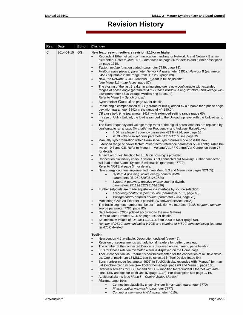
C 2014-01-15 GG New features with software revision 1.15xx or higher
Redundant Ethernet with communication handling for Network A and Network B is im-plemented. Refer to Menu 5.1 – Interfaces on page 86 for details and further description on page 171ff.
System update function added (parameter 7789, page 85).
Modbus slave (device) parameter Network A (parameter 5351) / Network B (parameter 5451) adjustable in the range from 0 to 255 (page 89).
Now, the Network B-UDP/Modbus IP_Addr is full adjustable (see Menu 5.1 – Interfaces, page 87).
The closing of the last Breaker in a ring structure is now configurable with extended ranges of phase angle (parameter 4717 Phase window in ring structure) and voltage win-dow (parameter 4718 Voltage window ring structure). Refer to Menu 1 – Synchronizer/
Synchronizer Control on page 66 for details.
Phase angle compensation MCB (parameter 8841) added by a tunable for a phase angle deviation (parameter 8842) in the range of +/- 180.0°.
CB close hold time (parameter 3417) with extended setting range (page 66).
In case of Utility Unload, the load is ramped to the Unload trip level with the Unload ramp rate.
The fixed frequency and voltage ramp rates of the digital potentiometers are replaced by configurable ramp rates (%rated/s) for Frequency- and Voltage- Raise/Lower.
f: DI raise/lower frequency parameter 4713/ 4714; see page 66
V: DI voltage raise/lower parameter 4715/4716; see page 75
Manually synchronization within Permissive Synchronizer mode possible now.
Extended range of power factor: Power factor reference parameter 5620 configurable be-tween - 0.5 and 0.5. Refer to Menu 4 – Voltage/Var/PF Control/Var Control on page 77 for details.
A new Lamp Test function for LEDs on housing is provided.
Connection plausibility check: System B not connected but Auxiliary Busbar connected, will lead to the Alarm "System B mismatch" (parameter 7770). Refer to NOTE at page 34 for details.
New energy counters implemented (see Menu 5.3 and Menu 8 on pages 92/105):
System A pos./neg. active energy counter (kWh, parameters 2510&2520/2512&2524)
System A pos./neg. reactive energy counter (kvarh, parameters 2511&2522/2513&2526)
Further setpoints are made adjustable via interface by source selection:
Frequency control setpoint source (parameter 7783, page 65)
Voltage control setpoint source (parameter 7784, page 75)
Monitoring GAP via Ethernet is possible (Woodward service, only!).
The Basic segment number can be set in addition via Interface (Basic segment number source parameter 7786, page 83)
Data telegram 5200 updated according to the new features. Refer to Data Protocol 5200 on page 196 for details.
Set minimum values of IDs 10411..10415 from 0000 to 0001 (page 90).
Number of DSLC communicating (4708) and Number of MSLC communicating (parame-ter 4707) deleted.
ToolKit
New version 4.5 available. Description updated (page 49).
Revision of several menus with additional headers for better overview.
The number of the connected Device is displayed on each menu page heading.
LED for Phase rotation mismatch alarm is displayed on the Home page.
ToolKit connection via Ethernet is now implemented for the connection of multiple devic-es. One of maximum 16 MSLC can be selected in Tool Device (page 54).
Synchronizer mode (parameter 4602) in ToolKit display extended with “Manual” for man-ual synchronizer function (see ToolKit homepage, page 60 and Menu 8, page 103).
Overview screens for DSLC-2 and MSLC-2 modified for redundant Ethernet with addi-tional LED and text for each Unit ID (page 111ff). For description see page 171ff.
Additional alarms (see Menu 8 – Control Status Monitor/
Alarms, page 104):
Connection plausibility check System B mismatch (parameter 7770)
Phase rotation mismatch (parameter 7777)
Communication error NW A (parameter 4615),

Manual 37444C MSLC-2 - Master Synchronizer and Load Control
Page 4/220 © Woodward
Rev. Date Editor Changes
Communication error NW B (parameter 7787)
Network A error (parameter 7792), Network B error (parameter 7793)
Devices not matched (parameter 7794)
New menus:
Menu 5.3 – Configure Counters (page 92)
Menu 7, 7.1 and 7.2 – Electrical Parameters (page 98) Corrections
Improved tie-breaker synchronization between two loadshare groups with bumpless transfer.
Improved tie-breaker unloading function with bumpless transfer, when the connected utili-ty MSLC has a closed breaker.
The detection of a dead busbar is independent on measured frequency—the voltage am-plitude is taken into account only.
Manual
Changes described related to the feature update listed above.
Updated terminal description (page 23).
Updated terminal 151, DI 23, and parameter 7789 named to “System update” (several pages and silk screen).
Minor corrections.
B 12-04-20 TE Minor corrections
A 11-05-13 TE Minor corrections New features Requirements: Master synchronizer and load control (MSLC-2) with software revision 1.1404 or higher and device revision A or higher.
Synchronizer description: Manual synchronizing. Refer to “Table 4-13: Ramping overview
Manual Synchronizing” on page 151 for details.
Modbus communication: Loss of connection. Refer to “Loss of Connection” on page 181 for details.
NEW 11-03-24 TE New Release

Manual 37444C MSLC-2 - Master Synchronizer and Load Control
© Woodward Page 5/220
Content
CHAPTER 1. GENERAL INFORMATION ..................................................................................... 12 Document Overview ............................................................................................................................... 12 Application .............................................................................................................................................. 13
MSLC-2 function summary .......................................................................................................... 13 Synchronizer .......................................................................................................................................... 13 Load Control ........................................................................................................................................... 14 Process Control ...................................................................................................................................... 16 Var/PF Control ....................................................................................................................................... 16 DSLC-2 / MSLC-2 Systems ................................................................................................................... 17
Control Relationships in a MSLC-DSLC System ......................................................................... 18
CHAPTER 2. INSTALLATION .................................................................................................... 19 Electrostatic Discharge Awareness ....................................................................................................... 19 Unpacking .............................................................................................................................................. 20 Location .................................................................................................................................................. 20 Housing .................................................................................................................................................. 21
Dimensions .................................................................................................................................. 21 Installation .................................................................................................................................... 22 Terminal Arrangement ................................................................................................................. 23 LEDs ............................................................................................................................................ 23
Wiring Diagrams ..................................................................................................................................... 24 Connections ........................................................................................................................................... 26
Power Supply ............................................................................................................................... 27 Voltage Measuring ....................................................................................................................... 28 Current Measuring ....................................................................................................................... 37 Power Factor Definition................................................................................................................ 40 Discrete Inputs ............................................................................................................................. 42 Relay Outputs .............................................................................................................................. 44 Analog Inputs ............................................................................................................................... 46 Interfaces ..................................................................................................................................... 47
CHAPTER 3. CONFIGURATION & OPERATION ........................................................................... 49 Configuration via PC .............................................................................................................................. 49
Install ToolKit Configuration and Visualization Software ............................................................. 49 Install ToolKit Software ................................................................................................................ 49 Install ToolKit Configuration Files ................................................................................................ 50 Starting ToolKit Software ............................................................................................................. 51 Configure ToolKit Software .......................................................................................................... 52 Connecting ToolKit and the MSLC-2 Unit .................................................................................... 53 View MSLC-2 Data with ToolKit ................................................................................................... 57 Configuring the MSLC-2 with ToolKit ........................................................................................... 58 The MSLC-2 Version Page .......................................................................................................... 59
Menu (Setpoint) Description................................................................................................................... 60 MSLC-2 – Homepage .................................................................................................................. 60 Menu 1 – Synchronizer ................................................................................................................ 65 Menu 2 – Load Control ................................................................................................................ 69 Menu 3 – Process Control ........................................................................................................... 73 Menu 4 – Voltage/Var/PF Control ................................................................................................ 75 Menu 5 – Configuration................................................................................................................ 79 Menu 6 – Analog Inputs ............................................................................................................... 94 Menu 7, 7.1 and 7.2 – Electrical Parameters .............................................................................. 98 Menu 7.1 – System A................................................................................................................... 98 Menu 7.2 – System B................................................................................................................. 101 Menu 8 – Control Status Monitor ............................................................................................... 103 Menu 9 – Discrete Inputs / Discrete (Relay) Outputs ................................................................ 106

Manual 37444C MSLC-2 - Master Synchronizer and Load Control
Page 6/220 © Woodward
Menu 0 – Diagnostics ................................................................................................................ 109 Overview Pages ........................................................................................................................ 111
Prestart Setup Procedure .................................................................................................................... 114 Configuration Menu ................................................................................................................... 114 Prestart Segmenting Setup ....................................................................................................... 115 Prestart Synchronizer Setup ..................................................................................................... 119 Prestart Load Control Setup ...................................................................................................... 119 Prestart Process Control Setup ................................................................................................. 119 Prestart Var/Power Factor Control Setup .................................................................................. 119
MSLC-2 Control Adjustments .............................................................................................................. 120 Calibration Check ................................................................................................................................ 120 Synchronizer Adjustments ................................................................................................................... 121
Preliminary Synchronizer Adjustments...................................................................................... 121 Phase Matching Synchronizer ................................................................................................... 121 Slip Frequency Synchronizer .................................................................................................... 122 Final Synchronizer Setup .......................................................................................................... 123
Voltage Matching Adjustments ............................................................................................................ 124 Preliminary Voltage Matching Setup ......................................................................................... 124 Final Voltage Matching Setup ................................................................................................... 124
Load Control Adjustment ..................................................................................................................... 125 Base Load Mode Setup ............................................................................................................. 125 Remote Base Load .................................................................................................................... 125 Import/Export Mode Setup ........................................................................................................ 126 Remote Import/Export Setup ..................................................................................................... 126 Final Load Control Setup ........................................................................................................... 127
Process Control Adjustment ................................................................................................................ 128 Var/PF Control Adjustment .................................................................................................................. 129
Constant Generator Power Factor Setup .................................................................................. 129 PF Control at the Utility - Setup ................................................................................................. 130 Remote PF Control at the Utility - Setup ................................................................................... 130 Var Control at the Utility - Setup ................................................................................................ 131
CHAPTER 4. SYNCHRONIZER DESCRIPTION ........................................................................... 132 Introduction .......................................................................................................................................... 132 Functional Description ......................................................................................................................... 132
Operating Modes ....................................................................................................................... 132 Measurement Connections (Examples) .................................................................................... 134 Dead Bus Closure – Multiple Units ............................................................................................ 146 Deadbus Closure Mismatch Alarm ............................................................................................ 147 Voltage Matching ....................................................................................................................... 148 Phase Matching Synchronizing ................................................................................................. 148 Slip Frequency Synchronizing ................................................................................................... 148 Permissive Mode / Synch-Check Function ............................................................................... 148 GCB Maximum Closing Attempts .............................................................................................. 149 Auto re-synchronization ............................................................................................................. 149 Reclose limit alarm .................................................................................................................... 149 Synchronizer Timer ................................................................................................................... 149 Logic Charter GCB Closure ....................................................................................................... 150 Ramping .................................................................................................................................... 151
Manual Synchronizing ......................................................................................................................... 153 Frequency Setpoint ................................................................................................................... 153 Voltage Setpoint ........................................................................................................................ 153 Breaker Close ............................................................................................................................ 154 Reset Frequency / Voltage Setpoints Back To Rated (50 Hz or 60 Hz) ................................... 154
CHAPTER 5. REAL POWER CONTROL DESCRIPTION .............................................................. 155 Introduction .......................................................................................................................................... 155 MSLC-2 / DSLC-2 Interface ................................................................................................................. 155 Base Load Mode .................................................................................................................................. 155 Import / Export Mode ........................................................................................................................... 156
Manual 37444C MSLC-2 - Master Synchronizer and Load Control
© Woodward Page 7/220
Process Control Mode .......................................................................................................................... 156 Remote Control .................................................................................................................................... 156 Automatic Power Transfer Control Functions ...................................................................................... 156
Ramping Between Modes .......................................................................................................... 156 Utility Unload .............................................................................................................................. 156 Local Unload .............................................................................................................................. 157
CHAPTER 6. VAR/POWER FACTOR CONTROL DESCRIPTION ................................................... 158 Introduction........................................................................................................................................... 158 Constant Generator Power Factor ....................................................................................................... 158 Power Factor Control ........................................................................................................................... 159 Var Control ........................................................................................................................................... 159
CHAPTER 7. PROCESS CONTROL DESCRIPTION .................................................................... 160 Introduction........................................................................................................................................... 160 Description ........................................................................................................................................... 160
CHAPTER 8. NETWORK / SYSTEM DESCRIPTION .................................................................... 163 Introduction........................................................................................................................................... 163 Description ........................................................................................................................................... 163
Applications without Segmenting ............................................................................................... 164 Applications with Segmenting .................................................................................................... 165 Not Supported Applications ....................................................................................................... 167
Remote Control by PLC ....................................................................................................................... 168 Interface Connection via RS-485 with Modbus Protocol ........................................................... 168 Interface Connection via Ethernet by Modbus/TCP Stack ........................................................ 169
CHAPTER 9. INTERFACE....................................................................................................... 170 Interface Overview ............................................................................................................................... 170
Communication management .................................................................................................... 171 Commissioning of the Communication Network System ........................................................... 172
Ethernet Load Sharing ......................................................................................................................... 174 Multi-Master Principle ................................................................................................................ 174 Load Share Monitoring............................................................................................................... 174 General Load Share Information ............................................................................................... 174
Modbus Communications ..................................................................................................................... 175 General Information ................................................................................................................... 175 Address Range .......................................................................................................................... 175 Visualization ............................................................................................................................... 176 Configuration .............................................................................................................................. 177 MSLC-2 Interface Remote Control ............................................................................................ 178
Changing Parameter Settings via Modus ............................................................................................ 185 Parameter Setting ...................................................................................................................... 185 Remotely Resetting the Default Values ..................................................................................... 187
Modbus Parameters ............................................................................................................................. 189 Serial Interface 1 ........................................................................................................................ 189 Serial Interface 2 ........................................................................................................................ 189 Network A – Modbus.................................................................................................................. 189 Network B – Modbus.................................................................................................................. 189
CHAPTER 10. APPLICATION ................................................................................................. 190 Phase Angle Compensation................................................................................................................. 190 Connecting 24 V Relays ....................................................................................................................... 195 Data Protocol 5200 .............................................................................................................................. 196 Introduction........................................................................................................................................... 206
Parameter List Columns ............................................................................................................ 206 Parameter List ...................................................................................................................................... 207 Product Service Options ...................................................................................................................... 216 Returning Equipment for Repair .......................................................................................................... 216
Packing a Control ....................................................................................................................... 217 Return Authorization Number RAN ............................................................................................ 217
Replacement Parts ............................................................................................................................... 217

Manual 37444C MSLC-2 - Master Synchronizer and Load Control
Page 8/220 © Woodward
How to Contact Woodward .................................................................................................................. 218 Engineering Services ........................................................................................................................... 218 Technical Assistance ........................................................................................................................... 219
Figures and Tables
Figures Figure 1-2: MSLC-2 Load Control Overview ........................................................................................................... 15 Figure 1-3: Multiple generators in isolated operation with tie-breaker .................................................................... 17 Figure 1-4: Multiple generators in isolated and utility parallel operation with utility- and tie-breaker....................... 18 Figure 1-5: Control relationship in a MSLC-DSLC system ...................................................................................... 18 Figure 2-1: Housing MSLC-2 - dimensions ............................................................................................................. 21 Figure 2-2: Housing - drill plan................................................................................................................................ 22 Figure 2-3: MSLC-2 - terminal arrangement ........................................................................................................... 23 Figure 2-4: Wiring diagram - MSLC-2 - 1/2 ............................................................................................................. 24 Figure 2-5: Wiring diagram - MSLC-2 - 2/2 ............................................................................................................. 25 Figure 2-6: Power supply ........................................................................................................................................ 27 Figure 2-7: Power supply - crank waveform at maximum load ............................................................................... 27 Figure 2-8: Voltage measuring – system A ............................................................................................................. 28 Figure 2-9: Voltage measuring – system A windings, 3Ph 4W OD ......................................................................... 29 Figure 2-10: Voltage measuring – system A measuring inputs, 3Ph 4W OD ......................................................... 29 Figure 2-11: Voltage measuring – system A windings, 3Ph 4W ............................................................................. 30 Figure 2-12: Voltage measuring – system A measuring inputs, 3Ph 4W ................................................................ 30 Figure 2-13: Voltage measuring – system A windings, 3Ph 3W ............................................................................. 31 Figure 2-14: Voltage measuring – system A measuring inputs, 3Ph 3W ................................................................ 31 Figure 2-15: Voltage measuring – system B ........................................................................................................... 32 Figure 2-16: Voltage measuring – system B measuring inputs, 1Ph 2W (phase-neutral) ....................................... 33 Figure 2-17: Voltage measuring – system B measuring inputs, 1Ph 2W (phase-phase) ........................................ 33 Figure 2-18: Voltage measuring – auxiliary system B ............................................................................................. 34 Figure 2-19: Voltage measuring - auxiliary system B PT windings, 3Ph 4W .......................................................... 35 Figure 2-20: Voltage measuring - auxiliary system B measuring inputs, 3Ph 4W................................................... 35 Figure 2-21: Voltage measuring - auxiliary system B PT windings, 3Ph 3W .......................................................... 36 Figure 2-22: Voltage measuring - auxiliary system B measuring inputs, 3Ph 3W................................................... 36 Figure 2-23: Current measuring – system A ........................................................................................................... 37 Figure 2-24: Current measuring – system A, L1 L2 L3 ........................................................................................... 38 Figure 2-25: Current measuring - system A, phase Lx ........................................................................................... 38 Figure 2-26: Power measuring - direction of power ................................................................................................ 39 Figure 2-27: Phasor diagram – inductive / capacitive ............................................................................................. 41 Figure 2-28: Discrete inputs - alarm/control input - positive signal ......................................................................... 42 Figure 2-29: Discrete inputs - alarm/control input - negative signal ........................................................................ 42 Figure 2-30: Relay outputs ..................................................................................................................................... 44 Figure 2-31: Analog inputs - wiring two-pole senders using a voltage signal ......................................................... 46 Figure 2-32: Analog inputs - wiring two-pole senders (external jumper used for current signal) ............................ 46 Figure 2-33: RS-485 interface #1 - overview .......................................................................................................... 47 Figure 2-34: RS-485 Modbus - connection for half-duplex operation ..................................................................... 47 Figure 2-35: RS-485 Modbus - connection for full-duplex operation....................................................................... 47 Figure 2-36: RS-232 interface - overview ............................................................................................................... 48 Figure 2-37: RJ-45 interfaces - overview ................................................................................................................ 48 Figure 3-1: ToolKit - visualization screen ................................................................................................................ 57 Figure 3-2: ToolKit - analog value trending screen ................................................................................................. 57 Figure 3-3: ToolKit - configuration screen ............................................................................................................... 58 Figure 3-4: ToolKit -version page ........................................................................................................................... 59 Figure 3-5: ToolKit - home page (MSLC-2 configured as utility breaker control) .................................................... 60 Figure 3-6: ToolKit - home page (MSLC-2 configured as tie-breaker control) ........................................................ 61 Figure 3-10: ToolKit - home page - MSLC-2 configured as utility breaker control .................................................. 63 Figure 3-11: ToolKit - home page - MSLC-2 configured as tie-breaker control....................................................... 64 Figure 3-12: ToolKit - home page - segments ........................................................................................................ 64 Figure 3-13: ToolKit – synchronizer ........................................................................................................................ 65 Figure 3-17: ToolKit – load control .......................................................................................................................... 69 Figure 3-22: ToolKit – process control .................................................................................................................... 73 Figure 3-26: ToolKit – voltage/var/pf control ........................................................................................................... 75
Manual 37444C MSLC-2 - Master Synchronizer and Load Control
© Woodward Page 9/220
Figure 3-31: ToolKit – configuration ........................................................................................................................ 79 Figure 3-38: ToolKit – interfaces ............................................................................................................................. 86 Figure 3-47: ToolKit – system management ........................................................................................................... 90 Figure 3-53: ToolKit – configure counters ............................................................................................................... 92 Figure 3-55: ToolKit – analog inputs ....................................................................................................................... 94 Figure 3-56: ToolKit – relevant fields for remote load reference input ..................................................................... 94 Figure 3-57: ToolKit – relevant fields for remote process reference input ............................................................... 95 Figure 3-59: ToolKit – process signal input ............................................................................................................. 96 Figure 3-61: ToolKit – reactive load input................................................................................................................ 97 Figure 3-63: ToolKit – electrical parameters ........................................................................................................... 98 Figure 3-64: ToolKit – electrical parameters System A ........................................................................................... 98 Figure 3-74: ToolKit – electrical parameters System B ......................................................................................... 101 Figure 3-83: ToolKit – control status monitor ........................................................................................................ 103 Figure 3-88: ToolKit – discrete inputs / relay outputs ............................................................................................ 106 Figure 3-93: ToolKit – diagnostics ......................................................................................................................... 109 Figure 3-96: ToolKit – MSLC-2 overview page ..................................................................................................... 112 Figure 3-97: ToolKit – DSLC-2 overview page ...................................................................................................... 113 Figure 3-98: Example of an online diagram – step 1 ............................................................................................. 115 Figure 3-99: Example of an online diagram with segment numbers and segment connector feedbacks .............. 116 Figure 3-100: Example of an online diagram with according network ................................................................... 117 Figure 3-101: Example of an online diagram with all required information to setup the units................................ 118 Figure 3-102: Power measurement ....................................................................................................................... 120 Figure 4-1: Synchronizer block diagram................................................................................................................ 133 Figure 4-2: Low voltage system 480 V / 277 V – 3-phase with neutral ................................................................. 134 Figure 4-3: Low voltage system 480 V / 277 V – 3-phase with neutral ................................................................. 135 Figure 4-4: Low voltage system 480 V – 3-phase with neutral .............................................................................. 136 Figure 4-5: Low voltage system 600 V / 346 V – 3-phase ..................................................................................... 137 Figure 4-6: Low voltage system 600 V / 346 V – 3-phase ..................................................................................... 138 Figure 4-7: Low voltage system 600 V / 346 V – 3-phase ..................................................................................... 139 Figure 4-8: Low voltage system 600 V / 346 V – 3-phase with neutral ................................................................. 140 Figure 4-9: Low voltage system 600 V / 346 V – 3-phase with neutral ................................................................. 141 Figure 4-10: Low voltage system 600 V / 346 V – 3-phase with neutral ............................................................... 142 Figure 4-11: Low voltage system 600 V / 346 V – 3-phase with neutral ............................................................... 143 Figure 4-12: Middle voltage system 20 kV – 3-phase without neutral ................................................................... 144 Figure 4-13: Middle voltage system 20 kV – 3-phase without neutral ................................................................... 145 Figure 4-14: Dead bus closing – Example of dead busbar closure arbitration ...................................................... 146 Figure 4-15: Logic charter CB closure .................................................................................................................. 150 Figure 7-1: Diagram process control ..................................................................................................................... 162 Figure 8-1: Multiple generators in isolated operation without tie-breakers ............................................................ 164 Figure 8-2: Multiple generators in isolated / parallel to utility operation without tie-breakers................................. 164 Figure 8-3: Isolated operation with multiple generator and tie-breaker ................................................................. 165 Figure 8-4: Isolated / utility parallel operation with multiple generator and tie-breaker .......................................... 165 Figure 8-5: Isolated / utility parallel operation with multiple generator, tie-breaker and generator group breaker . 166 Figure 8-6: Isolated operation with multiple generator and tie-breaker (ring option) ............................................. 166 Figure 8-7: Not supported application ................................................................................................................... 167 Figure 8-8: Not supported application ................................................................................................................... 167 Figure 8-9: Visualization and remote control by PLC via RS-485 interface ........................................................... 168 Figure 9-1: MSLC-2 - interface overview (housing - side view) ............................................................................. 170 Figure 9-2: Modbus - visualization configurations ................................................................................................. 176 Figure 9-3: Modbus - sending binary digital orders over interface ........................................................................ 180 Figure 9-4: Modbus – loss of connection .............................................................................................................. 182 Figure 9-5: Modbus - configuration example 1 - active power ............................................................................... 183 Figure 9-6: Modbus - configuration example 2 – power factor .............................................................................. 184 Figure 9-7: Modbus - configuration example 1 ...................................................................................................... 185 Figure 9-8: Modbus - configuration example 2 ...................................................................................................... 186 Figure 9-9: Modbus - configuration example 3 ...................................................................................................... 186 Figure 9-10: Modbus - remote control parameter 1701 ......................................................................................... 187 Figure 9-11: Modbus - write register - enable the resetting procedure via RS-232 or Modbus TCP/IP ................. 187 Figure 9-12: Modbus - remote control parameter 1701 ......................................................................................... 188 Figure 9-13: Modbus - write register - resetting the default values ....................................................................... 188 Fig. 201: Phase angle compensation MCB ........................................................................................................... 190 Figure 10-1: Interference suppressing circuit - connection.................................................................................... 195
Tables
Table 1-1: Manual - overview .................................................................................................................................. 12
Manual 37444C MSLC-2 - Master Synchronizer and Load Control
Page 10/220 © Woodward
Table 2-1: Conversion chart - wire size .................................................................................................................. 26 Table 2-2: Power supply - terminal assignment ...................................................................................................... 27 Table 2-3: Voltage measuring – terminal assignment – System A voltage ............................................................. 28 Table 2-4: Voltage measuring - terminal assignment – System A, 3Ph 4W OD ..................................................... 29 Table 2-5: Voltage measuring – terminal assignment – system A, 3Ph 4W ........................................................... 30 Table 2-6: Voltage measuring - terminal assignment – system A, 3Ph 3W ............................................................ 31 Table 2-7: Voltage measuring - terminal assignment – system B voltage .............................................................. 32 Table 2-8: Voltage measuring - terminal assignment – system B, 1Ph 2W (phase-neutral) ................................... 33 Table 2-9: Voltage measuring - terminal assignment – system B, 1Ph 2W (phase-phase) .................................... 33 Table 2-10: Voltage measuring - terminal assignment - auxiliary system B voltage ............................................... 34 Table 2-11: Voltage measuring - terminal assignment - auxiliary system B, 3Ph 4W ............................................. 35 Table 2-12: Voltage measuring - terminal assignment - auxiliary system B, 3Ph 3W ............................................. 36 Table 2-13: Current measuring - terminal assignment – system A current ............................................................. 37 Table 2-14: Current measuring - terminal assignment – system A, L1 L2 L3 ......................................................... 38 Table 2-15: Current measuring - terminal assignment - system A, phase Lx ......................................................... 38 Table 2-16: Power Measuring – sign displayed – Utility / Tie ................................................................................. 39 Table 2-17: Power measuring - terminal assignment ............................................................................................. 39 Table 2-18: Discrete input - terminal assignment 1/2 ............................................................................................. 42 Table 2-19: Discrete input - terminal assignment 2/2 ............................................................................................. 43 Table 2-21: Relay outputs - terminal assignment ................................................................................................... 44 Table 2-22: Relay outputs driven by … .................................................................................................................. 45 Table 2-23: Analog inputs - terminal assignment - wiring two-pole senders ........................................................... 46 Table 2-24: RS-485 interface #1 - pin assignment ................................................................................................. 47 Table 2-25: RS-232 interface - pin assignment ...................................................................................................... 48 Table 2-26: RJ-45 interfaces - pin assignment ....................................................................................................... 48 Table 3-7: Parameter – homepage - General ......................................................................................................... 62 Table 3-8: Parameter – homepage - Setpoints ....................................................................................................... 62 Table 3-9: Parameter – homepage – Process control ............................................................................................ 62 Table 3-14: Parameter – synchronizer – PID frequency control ............................................................................. 66 Table 3-15: Parameter – synchronizer – PID voltage control ................................................................................. 66 Table 3-16: Parameter – synchronizer – synchronizer control ............................................................................... 68 Table 3-18: Parameter – load control – PID import/export control .......................................................................... 69 Table 3-19: Parameter – load control – power control monitoring .......................................................................... 70 Table 3-20: Parameter – load control – power control ............................................................................................ 71 Table 3-21: Parameter – load control – import/export level via interface ................................................................ 72 Table 3-23: Parameter – process control – PID process control ............................................................................ 73 Table 3-24: Parameter – process control – process control ................................................................................... 74 Table 3-25: Parameter – process control – process signal input monitoring .......................................................... 74 Table 3-27: Parameter – voltage/var/pf control – voltage control ........................................................................... 75 Table 3-28: Parameter – voltage/var/pf control – voltage monitoring ..................................................................... 76 Table 3-29: Parameter – voltage/var/pf control – PID VAR control ......................................................................... 76 Table 3-30: Parameter – voltage/var/pf control – VAR control................................................................................ 78 Table 3-32: Parameter – configuration ................................................................................................................... 81 Table 3-33: Parameter – configuration – transformer ............................................................................................. 82 Table 3-34: Parameter – configuration – operating ranges .................................................................................... 83 Table 3-35: Parameter – configuration – system settings ....................................................................................... 84 Table 3-36: Parameter – configuration – tie breaker .............................................................................................. 84 Table 3-37: Parameter – configuration – communication ....................................................................................... 85 Table 3-39: Parameter – interfaces – serial 1 – RS232 .......................................................................................... 86 Table 3-40: Parameter – interfaces – serial 1 – Modbus ........................................................................................ 87 Table 3-41: Parameter – interfaces – serial 2 – RS485 .......................................................................................... 87 Table 3-42: Parameter – interfaces – serial 2 – Modbus ........................................................................................ 87 Table 3-43: Parameter – interfaces – network A .................................................................................................... 87 Table 3-44: Parameter – interfaces – network B .................................................................................................... 88 Table 3-45: Parameter – interfaces – format Modbus protocol ............................................................................... 89 Table 3-46: Parameter – interfaces – Modbus TCP ............................................................................................... 89 Table 3-48: Parameter – system management – password system ....................................................................... 91 Table 3-49: Parameter – system management – password ................................................................................... 91 Table 3-50: Parameter – system management – active code levels ...................................................................... 92 Table 3-51: Parameter – system management – factory settings........................................................................... 92 Table 3-52: Parameter – system management – power supply ............................................................................. 92 Table 3-54: Parameter – configure counters .......................................................................................................... 93 Table 3-58: Parameter – analog inputs – reference input: remote load/process .................................................... 96 Table 3-60: Parameter – analog inputs – process signal input ............................................................................... 96 Table 3-62: Parameter – analog inputs – reactive load input ................................................................................. 97 Table 3-65: Parameter – System A – active power ................................................................................................ 98
Manual 37444C MSLC-2 - Master Synchronizer and Load Control
© Woodward Page 11/220
Table 3-66: Parameter – system A – reactive power .............................................................................................. 99 Table 3-67: Parameter – system A – apparent power ............................................................................................. 99 Table 3-68: Parameter – System A – voltage phase-phase .................................................................................... 99 Table 3-69: Parameter – System A – voltage phase-neutral ................................................................................... 99 Table 3-70: Parameter – system A – power factor .................................................................................................. 99 Table 3-71: Parameter – System A – current ........................................................................................................ 100 Table 3-72: Parameter – System A – frequency ................................................................................................... 100 Table 3-73: Parameter – system A – phase rotation ............................................................................................. 100 Table 3-75: Parameter – system B – voltage ........................................................................................................ 101 Table 3-76: Parameter – system B – frequency .................................................................................................... 101 Table 3-77: Parameter – system B – phase angle ................................................................................................ 101 Table 3-78: Parameter – System B – phase rotation ............................................................................................ 101 Table 3-79: Parameter – aux. system B – voltage phase-phase ........................................................................... 102 Table 3-80: Parameter – aux. system B – voltage phase-neutral ......................................................................... 102 Table 3-81: Parameter – aux. system B – frequency ............................................................................................ 102 Table 3-82: Parameter – auxiliary system B – phase rotation ............................................................................... 102 Table 3-84: Parameter – control status monitor .................................................................................................... 104 Table 3-85: Parameter – control status monitor - alarms ...................................................................................... 105 Table 3-86: Parameter – control status monitor – System A energy counters ...................................................... 105 Table 3-87: Parameter – control status monitor – communication management .................................................. 105 Table 3-89: Parameter – discrete inputs / outputs – discrete inputs ..................................................................... 107 Table 3-90: Parameter – discrete inputs / outputs – discrete input source............................................................ 108 Table 3-91: Parameter – discrete inputs / outputs – relay outputs ........................................................................ 108 Table 3-92: Parameter – discrete inputs / outputs – segments ............................................................................. 108 Table 3-94: Parameter – diagnostics .................................................................................................................... 110 Table 3-95: System Status quick info at overview pages ...................................................................................... 111 Table 3-30: Parameter – MSLC-2 overview page ................................................................................................. 112 Table 3-29: Parameter – DSLC-2 overview page ................................................................................................. 113 Table 4-1: Low voltage system 480 V / 277 V – 3-phase with neutral ................................................................... 134 Table 4-2: Low voltage system 480 V / 277 V – 3-phase with neutral ................................................................... 135 Table 4-3: Low voltage system 480 V – 3-phase with neutral ............................................................................... 136 Table 4-4: Low voltage system 600 V / 346 V – 3-phase ...................................................................................... 137 Table 4-5: Low voltage system 600 V / 346 V – 3-phase ...................................................................................... 138 Table 4-6: Low voltage system 600 V / 346 V – 3-phase ...................................................................................... 139 Table 4-7: Low voltage system 600 V / 346 V – 3-phase with neutral ................................................................... 140 Table 4-8: Low voltage system 600 V / 346 V – 3-phase with neutral ................................................................... 141 Table 4-9: Low voltage system 600 V / 346 V – 3-phase with neutral ................................................................... 142 Table 4-10: Low voltage system 600 V / 346 V – 3-phase with neutral ................................................................. 143 Table 4-11: Middle voltage system 20 kV – 3-phase without neutral .................................................................... 144 Table 4-12: Middle voltage system 20 kV – 3-phase without neutral .................................................................... 145 Table 4-13: Ramping overview ............................................................................................................................. 152 Table 9-1: MSLC-2 - Interfaces - overview ............................................................................................................ 170 Table 9-2: Modbus - address range ...................................................................................................................... 175 Table 9-3: Modbus - address range block read ..................................................................................................... 176 Table 9-4: Modbus - address calculation .............................................................................................................. 177 Table 9-5: Modbus - data types ............................................................................................................................ 177 Table 9-6: Modbus – sending setpoints over interface .......................................................................................... 178 Table 9-7: Modbus – sending binary digital orders over interface ......................................................................... 179 Table 9-8: Modbus – sending binary digital orders over interface ......................................................................... 181 Table 9-9: Modbus – password for serial interface 1 ............................................................................................ 185 Table 9-10: Modbus – generator rated voltage ..................................................................................................... 186 Table 9-11: Modbus – generator voltage measuring ............................................................................................. 186 Table 9-12: Modbus – reset default values ........................................................................................................... 187 Table 9-13: Modbus - serial interface 1 - parameters ........................................................................................... 189 Table 9-14: Modbus - serial interface 2 – parameters ........................................................................................... 189 Table 9-16: Modbus - TCP/IP Network A– parameters ......................................................................................... 189 Table 9-15: Modbus - TCP/IP Network B– parameters ......................................................................................... 189 Table 10-1: Technical Data ................................................................................................................................... 192 Table 10-2: Environmental Data ........................................................................................................................... 193 Table 10-3: Accuracy ............................................................................................................................................ 194 Table 10-4: Interference suppressing circuit for relays ......................................................................................... 195 Table 10-5: Data Protocol 5200 ............................................................................................................................ 205 (Sequence following ID number) ........................................................................................................................... 207 Table 10-6: Parameter list ..................................................................................................................................... 215

Manual 37444C MSLC-2 - Master Synchronizer and Load Control
Page 12/220 © Woodward
Chapter 1. General Information
Document Overview
≡≡≡≡≡≡≡≡≡≡≡≡≡≡≡≡≡≡≡≡≡≡≡≡≡ This manual describes the Woodward MSLC-2
TM Master Synchronizer and Load Control.
Type English German
MSLC-2
DSLC-2 – User Manual 37443 -
MSLC-2 – User Manual this manual 37444 -
Table 1-1: Manual - overview
Intended Use The unit must only be operated in the manner described by this manual. The prerequi-site for a proper and safe operation of the product is correct transportation, storage and installation as well as careful operation and maintenance.
NOTE This manual has been developed for a unit fitted with all available options. Inputs/outputs, functions, configuration screens and other details described, which do not exist on your unit, may be ignored.
The present manual has been prepared to enable the installation and commissioning of the unit. Due to the large variety of parameter settings, it is not possible to cover every combination. The manual is therefore only a guide.

Manual 37444C MSLC-2 - Master Synchronizer and Load Control
© Woodward Page 13/220
Application
≡≡≡≡≡≡≡≡≡≡≡≡≡≡≡≡≡≡≡≡≡≡≡≡≡ The Woodward MSLC-2™ control is the direct successor of the former MSLC™ master synchronizer and load control. The MSLC-2™ is a microprocessor-based overall plant load control designed for use in a system with Woodward DSLC-2
TM (“Digital Synchronizer and Load Control”) controls on each gen-
erator to provide utility synchronizing, paralleling, loading and unloading of a three-phase generating system. Applications allow up to 32 generators to be paralleled and controlled in conjunction with up to 16 MSLC-2. A dedicated Ethernet system provides seamless communications between DSLC-2
TM and
MSLC-2TM
units. A second Ethernet port is provided for customer remote control and monitoring capa-bility using Modbus TCP allowing DCS and PLC interfacing. Both together can be used as a redundant Ethernet system. Additionally a Modbus RTU is available through a separate RS-485 port.
MSLC-2 function summary
Original MSLC functions include: Selectable for phase matching or slip frequency synchronizing between the utility and a local
bus with voltage matching
Automatic system loading and unloading for bumpless load transfer
Import/export level control capability
Process control for cogeneration, pressure, maintenance or other process
Proportional loading of associated DSLC-2 controls in isochronous load sharing
Adjustable power factor control
Built in diagnostics with relay output
Multifunction adjustable high and low limit alarms and adjustable load switches with relay out-puts
Digital communications network to provide loading and power factor control of individual DSLC-2 equipped generators
Additional MSLC-2 functions include: Automatic dead bus closure capability for tie-breakers
Multiple utility breaker and tie-breaker MSLC-2s on the same bus segment
One dedicated Ethernet line for precise system communications between all DSLC-2s and MSLC-2s on the system
Ethernet Modbus/TCP for remote control and monitoring
Serial Modbus RS-485 for remote control and monitoring
Applications with up to 32 DSLC-2 and 16 MSLC-2
Automatic segment control (self recognizing of the segment)
Full setup, metering and diagnostic capability through the PC program ToolKit
Synchronizer
≡≡≡≡≡≡≡≡≡≡≡≡≡≡≡≡≡≡≡≡≡≡≡≡≡ Either phase matching or slip frequency synchronizing may be selected. Phase matching provides rap-id synchronizing for critical standby power applications. Slip frequency synchronizing ensures that the initial flow of power will be either out of the local system (export) or into the local system (import), de-pending on whether a positive or negative slip is chosen. For both synchronizing methods, the MSLC-2 uses actual slip frequency and breaker delay values to anticipate an adjustable minimum phase differ-ence between the utility and the local bus. Additional synchronizer functions include voltage matching,

Manual 37444C MSLC-2 - Master Synchronizer and Load Control
Page 14/220 © Woodward
time delayed automatic multi-shot reclosing, auto-resynchronizing and a synchronizer timeout alarm. Each of these features may be enabled or disabled during setup. The MSLC-2 control provides a safe automatic dead bus closure function. Deadbus closing permission is granted to only one DSLC-2 or MSLC-2 control in the whole system through locking techniques done over the communications network. The MSLC-2, configured as tie-breaker control, allows selecting different closure modes or all modes:
Alive bus A -> dead bus B
Dead bus A -> dead bus B
Alive bus B -> dead bus A
Load Control
≡≡≡≡≡≡≡≡≡≡≡≡≡≡≡≡≡≡≡≡≡≡≡≡≡ The MSLC-2 has four load control modes available:
Base load
Import/export
Process
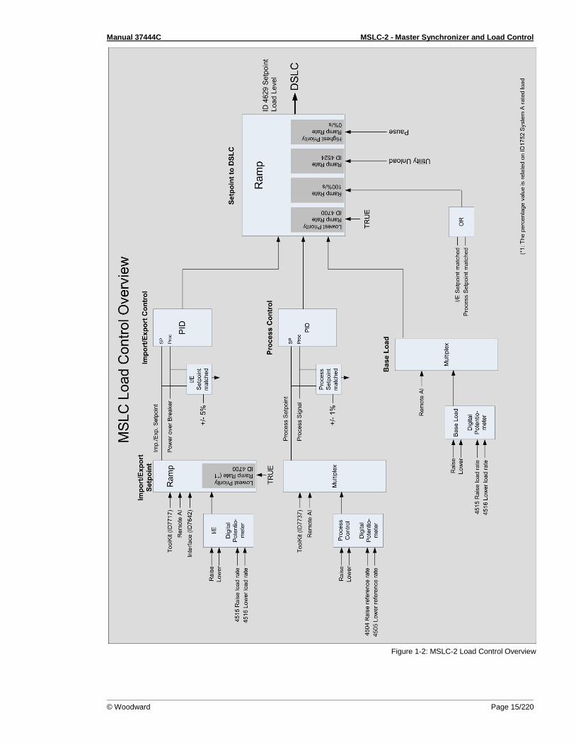
Utility unload Load control begins with the breaker closure of the utility and another discrete input selecting the load control mode wanted. If no load control mode is selected the MSLC-2 will be in the offline mode. The system load immediately prior to breaker closure is used as the starting base load reference. On com-mand, the adjustable ramp allows smooth, time controlled loading into a set import/export level. A ramp pause switch is provided to stop the ramp at any point. The import/export control is an integrating control. It adjusts the percentage of rated load carried by the individual generators, operating in isochronous load sharing, in order to maintain a set import/export or base load level. The MSLC-2 will maintain a constant base load or import/export level even with chang-ing utility frequencies. The MSLC-2 provides switch inputs to allow raising or lowering the internal digi-tal base load or import/export reference. The control also provides a remote analog signal input for ref-erence setting, if desired. (Signal variety: 0 to 20 mA, 4 to 20 mA, 0 to 5 V, 1 to 5 V and 0 to 10 V) The MSLC-2 is equipped with a utility unload switch, which provides an adjustable time controlled ramp to lower the base load or import/export level. When the level is below an adjustable threshold, the MSLC-2 issues a breaker open command to separate the utility from the local bus. The ramp pause switch can be used to stop the utility unload at any point. The maximum load that the MSLC-2 can tell the individual generators to carry is their rated loads. So, in the event that the plant load is greater than the capacity of the operating generators, the utility unload will stop when 100% rated load is reached on each of the operating generators. This prevents accidental overloading of the local generators. The MSLC-2 also includes two adjustable load switches which can be used for external functions or warnings when chosen system load levels are attained. The high and low limit switches may also be activated when 100% or 0% load signal to the generators is reached.
Manual 37444C MSLC-2 - Master Synchronizer and Load Control
© Woodward Page 15/220
Figure 1-2: MSLC-2 Load Control Overview

Manual 37444C MSLC-2 - Master Synchronizer and Load Control
Page 16/220 © Woodward
Process Control
≡≡≡≡≡≡≡≡≡≡≡≡≡≡≡≡≡≡≡≡≡≡≡≡≡ A process controller is provided for cogeneration, fluid level maintenance, pressure control or other ap-plications. An adjustable bandwidth signal input filter, flexible PID controller adjustments, selectable for direct or indirect action, allow the process control to be used in a wide variety of applications. An analog signal input (signal variety: 0 to 20mA, 4 to 20mA, 0 to 5V, 1 to 5V and 0 to 10V) provides the process signal to the MSLC-2. The MSLC-2 includes an internal digital process reference which may be controlled by the raise and lower switch contact inputs or by an external analog input signal as remote process reference. The MSLC-2 also has a Modbus address for process reference control. The output of the process control, like the import/export control, is the percentage of rated load setpoint to the individual generators in isochronous load sharing. An adjustable ramp allows smooth entry and exit from the process control mode. When the process control mode is selected, the load reference is ramped in a direction to reduce the error between the process input and the process reference. When the error is minimized or the reference first reaches ei-ther the high or low specified limits, the process controllers PID loop is activated. When the load refer-ence output reaches either 100% or 0%, the control will maintain that load reference until process con-trol is established. The MSLC-2 is not capable of overloading or reverse powering the generators in an attempt to meet the process reference. The high and low limit switches mentioned above can be used to indicate that either too many or too few generators are online to maintain the process within its limits.
Var/PF Control
≡≡≡≡≡≡≡≡≡≡≡≡≡≡≡≡≡≡≡≡≡≡≡≡≡ The var/PF function controls the power factor on all of the DSLC-2 equipped machines operating in isochronous load sharing. The PF control begins on breaker closure. The MSLC-2 has three modes of Var/PF control (which are selected in Menu 4):
Constant generator power factor – sets the power factor reference on all of the DSLC-2 con-
trols to the internal reference chosen in the MSLC-2. The power factor can then be adjusted using the voltage raise and lower inputs. The voltage raise command will make the power fac-tor more lagging. Conversely, the voltage lower command will make the power factor more leading.
Utility tie power factor control – adjusts the power factor reference on all of the DSLC-2 con-
trols in isochronous load sharing in order to maintain the power factor across the utility tie.
Utility tie var control – adjusts the power factor reference on all of the DSLC-2 controls in
isochronous load sharing in order to maintain the level of vars being imported or exported from the utility.
The var/PF control mode begins with the load control mode selected. The constant generator power factor and the utility tie power factor control can have the reference setting controlled by an analog in-put (see Menu 6). By closing the voltage raise and lower discrete inputs you can select the analog re-mote input for reference control.
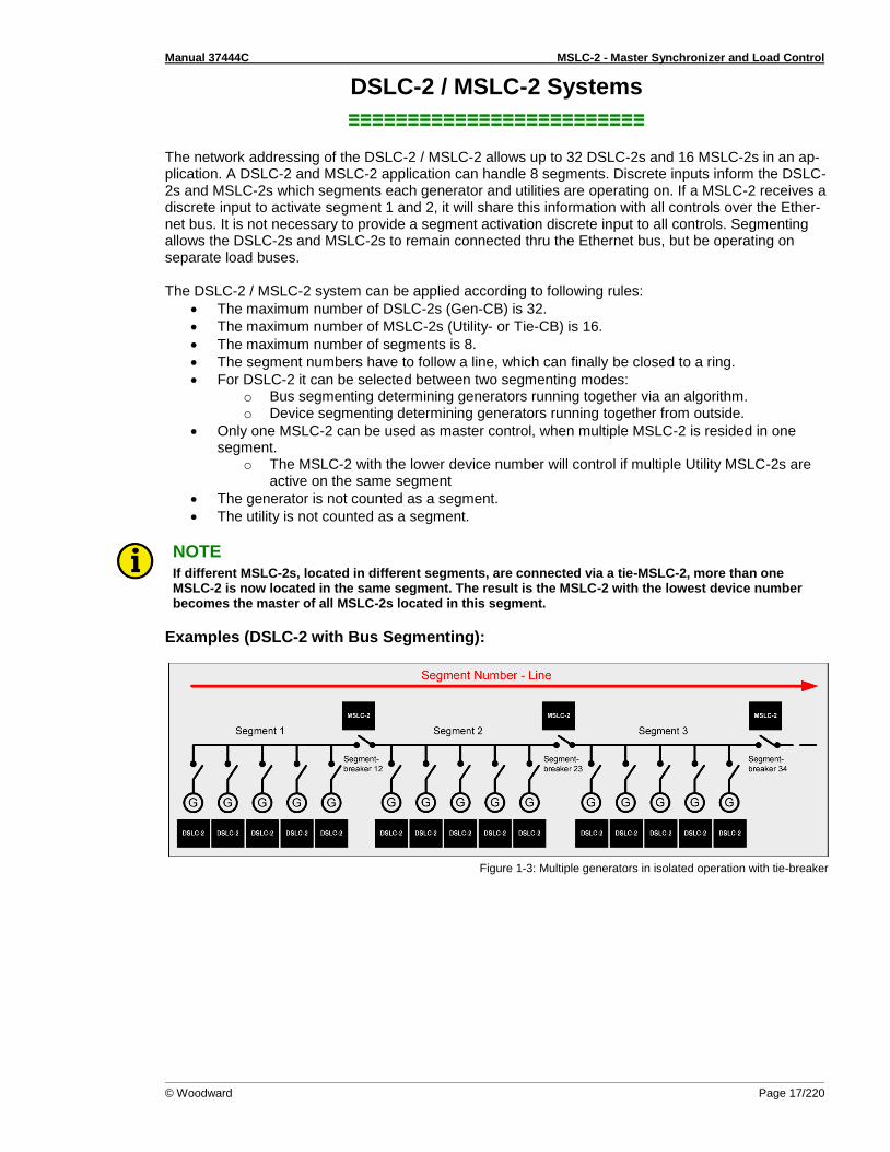
Manual 37444C MSLC-2 - Master Synchronizer and Load Control
© Woodward Page 17/220
DSLC-2 / MSLC-2 Systems
≡≡≡≡≡≡≡≡≡≡≡≡≡≡≡≡≡≡≡≡≡≡≡≡≡ The network addressing of the DSLC-2 / MSLC-2 allows up to 32 DSLC-2s and 16 MSLC-2s in an ap-plication. A DSLC-2 and MSLC-2 application can handle 8 segments. Discrete inputs inform the DSLC-2s and MSLC-2s which segments each generator and utilities are operating on. If a MSLC-2 receives a discrete input to activate segment 1 and 2, it will share this information with all controls over the Ether-net bus. It is not necessary to provide a segment activation discrete input to all controls. Segmenting allows the DSLC-2s and MSLC-2s to remain connected thru the Ethernet bus, but be operating on separate load buses. The DSLC-2 / MSLC-2 system can be applied according to following rules:
The maximum number of DSLC-2s (Gen-CB) is 32.
The maximum number of MSLC-2s (Utility- or Tie-CB) is 16.
The maximum number of segments is 8.
The segment numbers have to follow a line, which can finally be closed to a ring.
For DSLC-2 it can be selected between two segmenting modes: o Bus segmenting determining generators running together via an algorithm. o Device segmenting determining generators running together from outside.
Only one MSLC-2 can be used as master control, when multiple MSLC-2 is resided in one segment.
o The MSLC-2 with the lower device number will control if multiple Utility MSLC-2s are active on the same segment
The generator is not counted as a segment.
The utility is not counted as a segment.
NOTE If different MSLC-2s, located in different segments, are connected via a tie-MSLC-2, more than one MSLC-2 is now located in the same segment. The result is the MSLC-2 with the lowest device number becomes the master of all MSLC-2s located in this segment.
Examples (DSLC-2 with Bus Segmenting):
Figure 1-3: Multiple generators in isolated operation with tie-breaker

Manual 37444C MSLC-2 - Master Synchronizer and Load Control
Page 18/220 © Woodward
Figure 1-4: Multiple generators in isolated and utility parallel operation with utility- and tie-breaker
Control Relationships in a MSLC-DSLC System A MSLC / DSLC system is defined through minimum of one MSLC device and one DSLC device. A DSLC is only controlled by a MSLC, if:
The MSLC resides in the same segment
The MSLC has got a master function, like: o DI Sync Run o DI Sync Check o DI Manual (DI Sync
Check AND DI Sync Permissive)
o DI Base Load Con-trol
o DI Import/Export Control
o DI Process Control o DI Utility Unload
The according DSLC is lis-tening on the master MSLC, which means:
o DI Base Load is not active
o DI Process Control is not active
o DI Load/Unload is active
Figure 1-5: Control relationship in a MSLC-DSLC system

Manual 37444C MSLC-2 - Master Synchronizer and Load Control
© Woodward Page 19/220
Chapter 2. Installation
Electrostatic Discharge Awareness
≡≡≡≡≡≡≡≡≡≡≡≡≡≡≡≡≡≡≡≡≡≡≡≡≡ All electronic equipment is static-sensitive, some components more than others. To protect these com-ponents from static damage, you must take special precautions to minimize or eliminate electrostatic discharges. Follow these precautions when working with or near the control.
1. Before doing maintenance on the electronic control, discharge the static electricity on your body to ground by touching and holding a grounded metal object (pipes, cabinets, equipment, etc.).
2. Avoid the build-up of static electricity on your body by not wearing clothing made of synthetic
materials. Wear cotton or cotton-blend materials as much as possible because these do not store static electric charges as easily as synthetics.
3. Keep plastic, vinyl and Styrofoam materials (such as plastic or Styrofoam cups, cigarette
packages, cellophane wrappers, vinyl books or folders, plastic bottles, etc.) away from the con-trol, modules and work area as much as possible.
4. Opening the control cover may void the unit warranty.
Do not remove the printed circuit board (PCB) from the control cabinet unless absolutely nec-essary. If you must remove the PCB from the control cabinet, follow these precautions:
Ensure that the device is completely voltage-free (all connectors have to be disconnected).
Do not touch any part of the PCB except the edges.
Do not touch the electrical conductors, connectors, or components with conductive devices or with bare hands.
When replacing a PCB, keep the new PCB in the plastic antistatic protective bag it comes in until you are ready to install it. Immediately after removing the old PCB from the control cabi-net, place it in the antistatic protective bag.
CAUTION To prevent damage to electronic components caused by improper handling, read and observe the pre-cautions in Woodward manual 82715, Guide for Handling and Protection of Electronic Controls, Printed Circuit Boards and Modules.
NOTE The unit is capable to withstand an electrostatic powder coating process with a voltage of up to 85 kV and a current of up to 40 µA.

Manual 37444C MSLC-2 - Master Synchronizer and Load Control
Page 20/220 © Woodward
Unpacking
≡≡≡≡≡≡≡≡≡≡≡≡≡≡≡≡≡≡≡≡≡≡≡≡≡ Before unpacking the control, refer to the inside front cover of this manual for WARNINGS and CAUTIONS. Be careful when unpacking the control. Check for signs of damage such as bent or dented panels, scratches, loose or broken parts. If any damage is found, immediately notify the shipper.
Location
≡≡≡≡≡≡≡≡≡≡≡≡≡≡≡≡≡≡≡≡≡≡≡≡≡ When selecting a location for mounting the MSLC-2 control, consider the following:
• Protect the unit from direct exposure to water or to a condensation-prone environment. • The continuous operating range of the MSLC-2 control is –40 to +70 °C (–40 to +158 °F). • Provide adequate ventilation for cooling. Shield the unit from radiant heat sources. • Do not install near high-voltage, high-current devices. • Allow adequate space in front of the unit for servicing. • Do not install where objects can be dropped on the terminals. • Ground the chassis for proper safety and shielding. • The control must NOT be mounted on the engine.
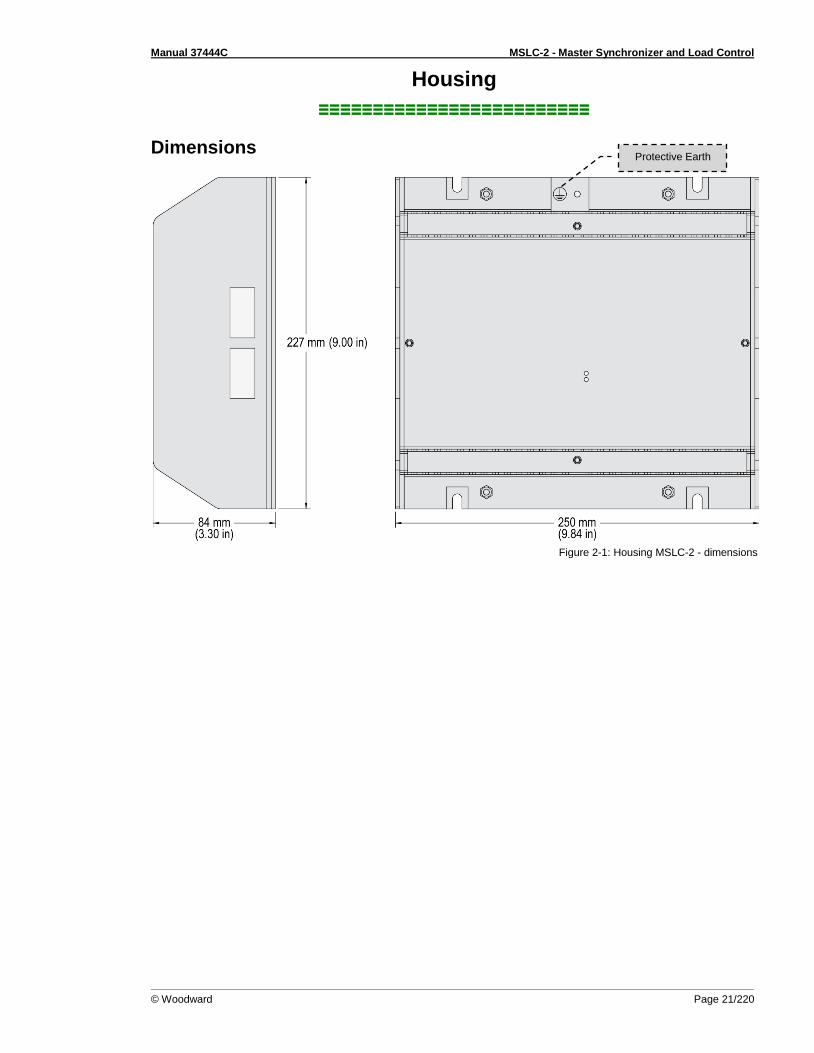
Manual 37444C MSLC-2 - Master Synchronizer and Load Control
© Woodward Page 21/220
Housing
≡≡≡≡≡≡≡≡≡≡≡≡≡≡≡≡≡≡≡≡≡≡≡≡≡
Dimensions
Figure 2-1: Housing MSLC-2 - dimensions
Protective Earth

Manual 37444C MSLC-2 - Master Synchronizer and Load Control
Page 22/220 © Woodward
Installation The unit is to be mounted to the switch cabinet back using four screws with a maximum diameter of 6 mm. Drill the holes according to the dimensions in Figure 2-2 (dimensions shown in mm).
Figure 2-2: Housing - drill plan
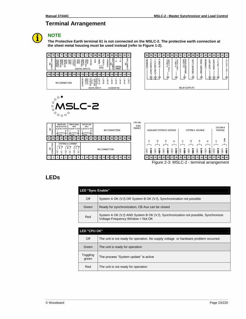
Manual 37444C MSLC-2 - Master Synchronizer and Load Control
© Woodward Page 23/220
Terminal Arrangement
NOTE The Protective Earth terminal 61 is not connected on the MSLC-2. The protective earth connection at the sheet metal housing must be used instead (refer to Figure 1-2).
Figure 2-3: MSLC-2 - terminal arrangement
LEDs
LED “Sync Enable”
Off System A OK (V,f) OR System B OK (V,f), Synchronization not possible
Green Ready for synchronization, CB Aux can be closed
Red System A OK (V,f) AND System B OK (V,f), Synchronization not possible, Synchronizer Voltage-Frequency Window = Not OK
LED "CPU OK"
Off The unit is not ready for operation. No supply voltage or hardware problem occurred.
Green The unit is ready for operation
Toggling green
The process “System update” is active
Red The unit is not ready for operation
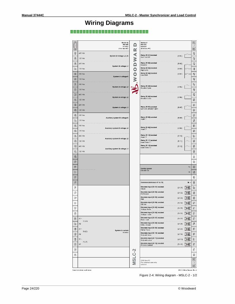
Manual 37444C MSLC-2 - Master Synchronizer and Load Control
Page 24/220 © Woodward
Wiring Diagrams
≡≡≡≡≡≡≡≡≡≡≡≡≡≡≡≡≡≡≡≡≡≡≡≡≡
Figure 2-4: Wiring diagram - MSLC-2 - 1/2

Manual 37444C MSLC-2 - Master Synchronizer and Load Control
© Woodward Page 25/220
Figure 2-5: Wiring diagram - MSLC-2 - 2/2

Manual 37444C MSLC-2 - Master Synchronizer and Load Control
Page 26/220 © Woodward
Connections
≡≡≡≡≡≡≡≡≡≡≡≡≡≡≡≡≡≡≡≡≡≡≡≡≡
WARNING All technical data and ratings indicated in this chapter are not definite! Only the values indicated in paragraph Appendix A. Technical Data on page 191 are valid!
The following chart may be used to convert square millimeters [mm²] to AWG and vice versa:
AWG mm² AWG mm² AWG mm² AWG mm² AWG mm² AWG mm²
30 0.05 21 0.38 14 2.5 4 25 3/0 95 600MCM 300
28 0.08 20 0.5 12 4 2 35 4/0 120 750MCM 400
26 0.14 18 0.75 10 6 1 50 300MCM 150 1000MCM 500
24 0.25 17 1.0 8 10 1/0 55 350MCM 185
22 0.34 16 1.5 6 16 2/0 70 500MCM 240
Table 2-1: Conversion chart - wire size

Manual 37444C MSLC-2 - Master Synchronizer and Load Control
© Woodward Page 27/220
Power Supply
WARNING – Protective Earth Protective Earth (PE) must be connected to the unit to avoid the risk of electric shock. The conductor providing the connection must have a wire larger than or equal to 2.5 mm² (14 AWG). The connection must be performed properly.
Please use the protective earth connection at the sheet metal housing (refer to Figure 2-1 on page 21).
Figure 2-6: Power supply
Figure Terminal Description Amax
A 63 12/24Vdc (8 to 40.0 Vdc) 2.5 mm²
B 64 0 Vdc 2.5 mm²
Table 2-2: Power supply - terminal assignment
Figure 2-7: Power supply - crank waveform at maximum load
NOTE Woodward recommends to use one of the following slow-acting protective devices in the supply line to terminal 63:
Fuse NEOZED D01 6A or equivalent
or
Miniature Circuit Breaker 6A / Type C (for example: ABB type: S271C6 or equivalent)
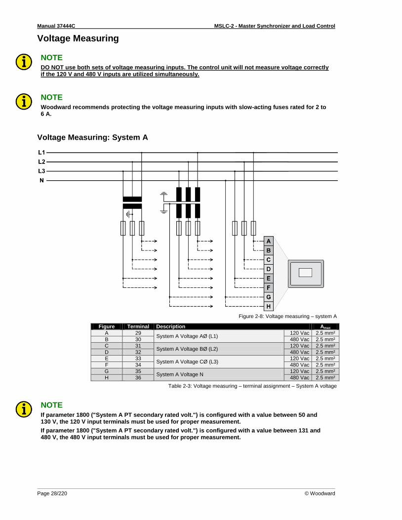
Manual 37444C MSLC-2 - Master Synchronizer and Load Control
Page 28/220 © Woodward
Voltage Measuring
NOTE DO NOT use both sets of voltage measuring inputs. The control unit will not measure voltage correctly if the 120 V and 480 V inputs are utilized simultaneously.
NOTE Woodward recommends protecting the voltage measuring inputs with slow-acting fuses rated for 2 to 6 A.
Voltage Measuring: System A
Figure 2-8: Voltage measuring – system A
Figure Terminal Description Amax
A 29 System A Voltage AØ (L1)
120 Vac 2.5 mm²
B 30 480 Vac 2.5 mm²
C 31 System A Voltage BØ (L2)
120 Vac 2.5 mm²
D 32 480 Vac 2.5 mm²
E 33 System A Voltage CØ (L3)
120 Vac 2.5 mm²
F 34 480 Vac 2.5 mm²
G 35 System A Voltage N
120 Vac 2.5 mm²
H 36 480 Vac 2.5 mm²
Table 2-3: Voltage measuring – terminal assignment – System A voltage
NOTE If parameter 1800 ("System A PT secondary rated volt.") is configured with a value between 50 and 130 V, the 120 V input terminals must be used for proper measurement.
If parameter 1800 ("System A PT secondary rated volt.") is configured with a value between 131 and 480 V, the 480 V input terminals must be used for proper measurement.

Manual 37444C MSLC-2 - Master Synchronizer and Load Control
© Woodward Page 29/220
Voltage Measuring: System A
Parameter Setting '3Ph 4W OD' (3-phase, 4-wire, Open delta) A generator system that is connected to the load through a 3-phase, 4-wire connection but have the device wired for a 3-phase, 3-wire installation may have the L2 phase grounded on the secondary side. In this application the device will be configured for 3-phase, 4-wire open delta for correct power meas-urement.
Figure 2-9: Voltage measuring – system A windings, 3Ph 4W OD
Figure 2-10: Voltage measuring – system A measuring inputs, 3Ph 4W OD
3Ph 4W OD Wiring terminals Note
Rated voltage (range) [1] 120 V (50 to 130 Veff.) [4] 480 V (131 to 480 Veff.) 1
Measuring range (max.) [1] 0 to 150 Vac [4] 0 to 600 Vac
Figure A C E G B D F H
MSLC-2 terminal 29 31 33 35 30 32 34 36
Phase L1 / AØ L2 / BØ L3 / CØ --- L1 / AØ L2 / BØ L3 / CØ ---
Table 2-4: Voltage measuring - terminal assignment – System A, 3Ph 4W OD
1 For different voltage systems, different wiring terminals have to be used.
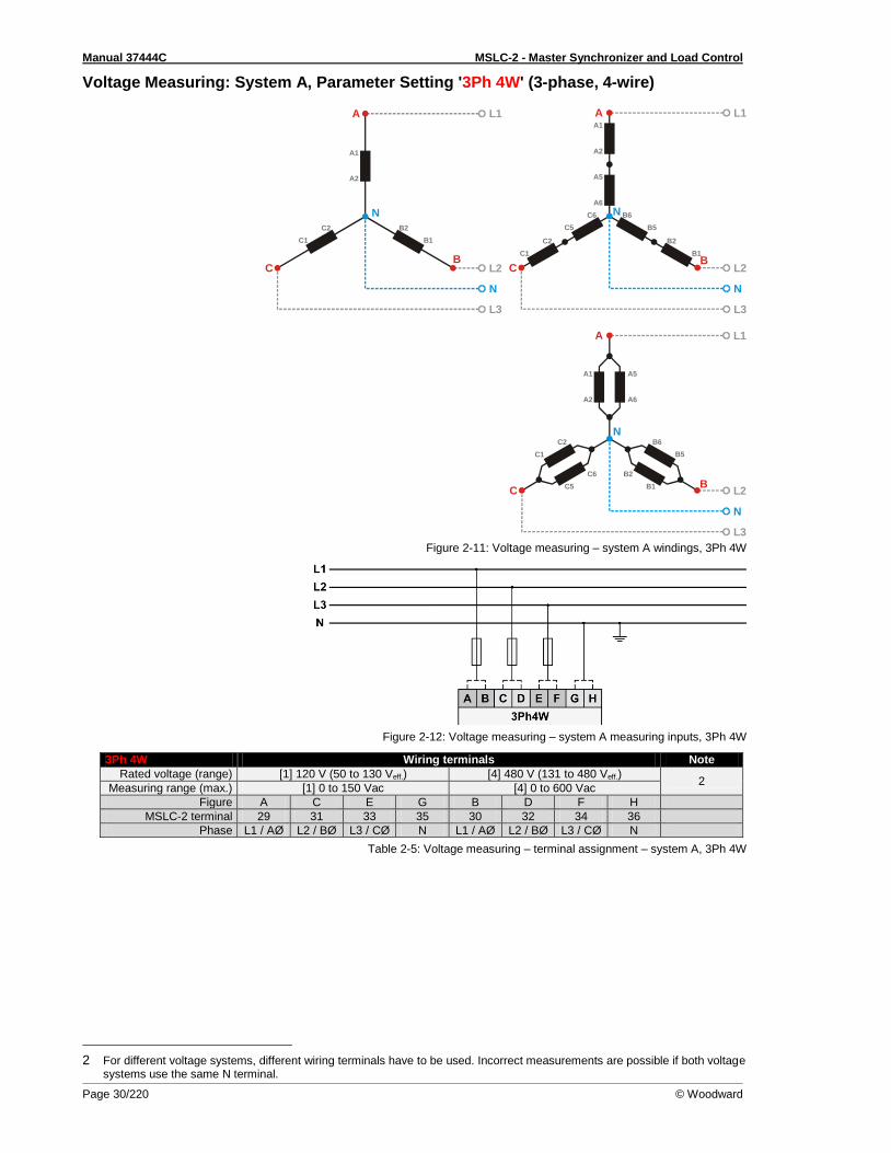
Manual 37444C MSLC-2 - Master Synchronizer and Load Control
Page 30/220 © Woodward
Voltage Measuring: System A, Parameter Setting '3Ph 4W' (3-phase, 4-wire)
Figure 2-11: Voltage measuring – system A windings, 3Ph 4W
Figure 2-12: Voltage measuring – system A measuring inputs, 3Ph 4W
3Ph 4W Wiring terminals Note
Rated voltage (range) [1] 120 V (50 to 130 Veff.) [4] 480 V (131 to 480 Veff.) 2
Measuring range (max.) [1] 0 to 150 Vac [4] 0 to 600 Vac
Figure A C E G B D F H
MSLC-2 terminal 29 31 33 35 30 32 34 36
Phase L1 / AØ L2 / BØ L3 / CØ N L1 / AØ L2 / BØ L3 / CØ N
Table 2-5: Voltage measuring – terminal assignment – system A, 3Ph 4W
2 For different voltage systems, different wiring terminals have to be used. Incorrect measurements are possible if both voltage systems use the same N terminal.
L1
L2
N
L3
N
A1
A2
A
B
B2
B1
C
C2
C1
L1
L2
N
L3
N
A1
A2
A
B
C6
C5
B6
B5
A5
A6
B2
B1
C
C2
C1
L1
L2
N
L3
N
A1
A2
A
B
B6
B5
A5
A6
C
C6
C5
B2
B1
C2
C1
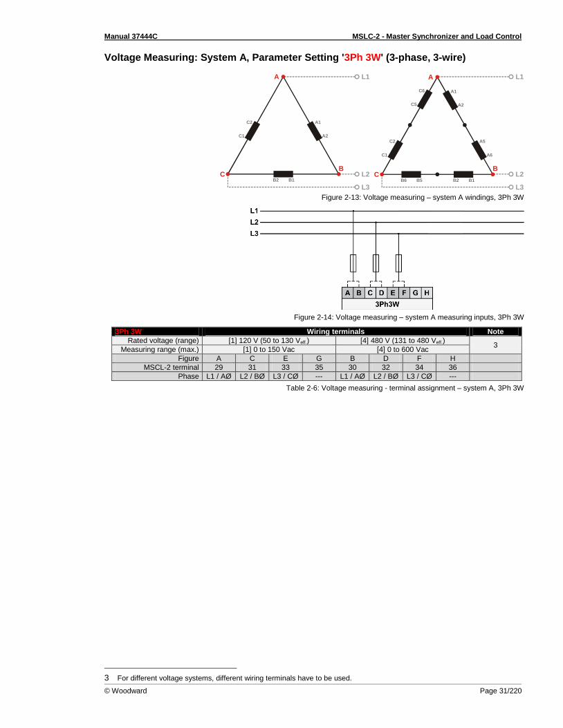
Manual 37444C MSLC-2 - Master Synchronizer and Load Control
© Woodward Page 31/220
Voltage Measuring: System A, Parameter Setting '3Ph 3W' (3-phase, 3-wire)
Figure 2-13: Voltage measuring – system A windings, 3Ph 3W
Figure 2-14: Voltage measuring – system A measuring inputs, 3Ph 3W
3Ph 3W Wiring terminals Note
Rated voltage (range) [1] 120 V (50 to 130 Veff.) [4] 480 V (131 to 480 Veff.) 3
Measuring range (max.) [1] 0 to 150 Vac [4] 0 to 600 Vac
Figure A C E G B D F H
MSCL-2 terminal 29 31 33 35 30 32 34 36
Phase L1 / AØ L2 / BØ L3 / CØ --- L1 / AØ L2 / BØ L3 / CØ ---
Table 2-6: Voltage measuring - terminal assignment – system A, 3Ph 3W
3 For different voltage systems, different wiring terminals have to be used.
L1
L2
L3B2
C2
C1
A1
A2
B1
A
BC
L1
L2
L3B1B2
C6
C5
A1
A2
B5B6
A
BC
C2
C1
A5
A6

Manual 37444C MSLC-2 - Master Synchronizer and Load Control
Page 32/220 © Woodward
Voltage Measuring: System B
Figure 2-15: Voltage measuring – system B
Figure Terminal Description Amax
A 37 System B Voltage AØ (L1)
120 Vac 2.5 mm²
B 38 480 Vac 2.5 mm²
C 39 System B Voltage BØ (L2) | N
120 Vac 2.5 mm²
D 40 480 Vac 2.5 mm²
Table 2-7: Voltage measuring - terminal assignment – system B voltage
NOTE If parameter 1803 ("System B PT secondary rated voltage") is configured with a value between 50 and 130 V, the 120 V input terminals must be used for proper measurement.
If parameter 1803 ("System B PT secondary rated voltage") is configured with a value between 131 and 480 V, the 480 V input terminals must be used for proper measurement.

Manual 37444C MSLC-2 - Master Synchronizer and Load Control
© Woodward Page 33/220
Voltage Measuring: System B, Parameter Setting '1Ph 2W' (1-phase, 2-wire)
NOTE The 1-phase, 2-wire measurement may be performed phase-neutral or phase-phase. Please note to configure and wire the MSLC-2 consistently. Refer to the chapter Configuration & Operation.
'1Ph 2W' Phase-Neutral Measuring
Figure 2-16: Voltage measuring – system B measuring inputs, 1Ph 2W (phase-neutral)
1Ph 2W Wiring terminals Note
Rated voltage (range) [1] 120 V (50 to 130 Veff.) [4] 480 V (131 to 480 Veff.) 4
Measuring range (max.) [1] 0 to 150 Vac [4] 0 to 600 Vac
Figure A C --- --- B D --- ---
MSLC-2 terminal 37 39 --- --- 38 40 --- ---
Phase L1 / AØ N --- --- L1 / AØ N --- ---
Table 2-8: Voltage measuring - terminal assignment – system B, 1Ph 2W (phase-neutral)
'1Ph 2W' Phase-Phase Measuring
Figure 2-17: Voltage measuring – system B measuring inputs, 1Ph 2W (phase-phase)
1Ph 2W Wiring terminals Note
Rated voltage (range) [1] 120 V (50 to 130 Veff.) [4] 480 V (131 to 480 Veff.) 5
Measuring range (max.) [1] 0 to 150 Vac [4] 0 to 600 Vac
Figure A C --- --- B D --- ---
MSLC-2 terminal 37 39 --- --- 38 40 --- ---
Phase L1 / AØ L2 / BØ --- --- L1 / AØ L2 / BØ --- ---
Table 2-9: Voltage measuring - terminal assignment – system B, 1Ph 2W (phase-phase)
4 For different voltage systems, different wiring terminals have to be used. Incorrect measurements are possible if both voltage systems use the same N terminal.
5 For different voltage systems, different wiring terminals have to be used. Incorrect measurements are possible if both voltage systems use the same N terminal.
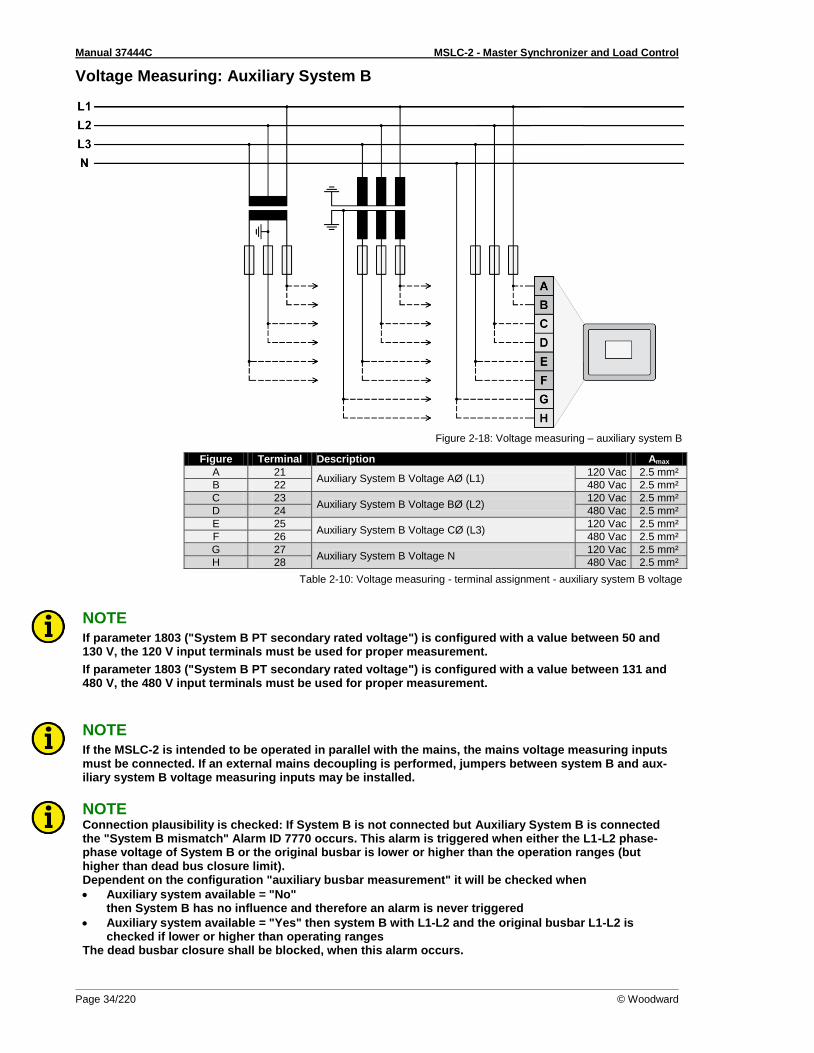
Manual 37444C MSLC-2 - Master Synchronizer and Load Control
Page 34/220 © Woodward
Voltage Measuring: Auxiliary System B
Figure 2-18: Voltage measuring – auxiliary system B
Figure Terminal Description Amax
A 21 Auxiliary System B Voltage AØ (L1)
120 Vac 2.5 mm²
B 22 480 Vac 2.5 mm²
C 23 Auxiliary System B Voltage BØ (L2)
120 Vac 2.5 mm²
D 24 480 Vac 2.5 mm²
E 25 Auxiliary System B Voltage CØ (L3)
120 Vac 2.5 mm²
F 26 480 Vac 2.5 mm²
G 27 Auxiliary System B Voltage N
120 Vac 2.5 mm²
H 28 480 Vac 2.5 mm²
Table 2-10: Voltage measuring - terminal assignment - auxiliary system B voltage
NOTE If parameter 1803 ("System B PT secondary rated voltage") is configured with a value between 50 and 130 V, the 120 V input terminals must be used for proper measurement.
If parameter 1803 ("System B PT secondary rated voltage") is configured with a value between 131 and 480 V, the 480 V input terminals must be used for proper measurement.
NOTE If the MSLC-2 is intended to be operated in parallel with the mains, the mains voltage measuring inputs must be connected. If an external mains decoupling is performed, jumpers between system B and aux-iliary system B voltage measuring inputs may be installed.
NOTE Connection plausibility is checked: If System B is not connected but Auxiliary System B is connected the "System B mismatch" Alarm ID 7770 occurs. This alarm is triggered when either the L1-L2 phase-phase voltage of System B or the original busbar is lower or higher than the operation ranges (but higher than dead bus closure limit). Dependent on the configuration "auxiliary busbar measurement" it will be checked when
Auxiliary system available = "No" then System B has no influence and therefore an alarm is never triggered
Auxiliary system available = "Yes" then system B with L1-L2 and the original busbar L1-L2 is checked if lower or higher than operating ranges
The dead busbar closure shall be blocked, when this alarm occurs.
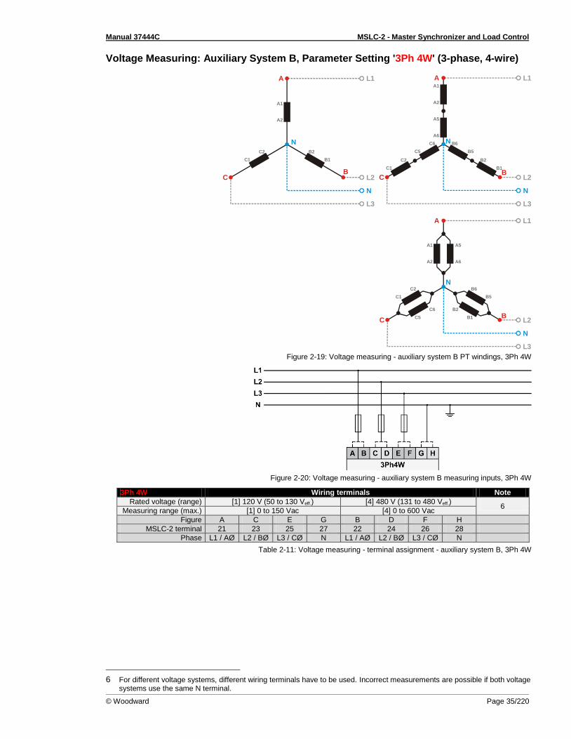
Manual 37444C MSLC-2 - Master Synchronizer and Load Control
© Woodward Page 35/220
Voltage Measuring: Auxiliary System B, Parameter Setting '3Ph 4W' (3-phase, 4-wire)
Figure 2-19: Voltage measuring - auxiliary system B PT windings, 3Ph 4W
Figure 2-20: Voltage measuring - auxiliary system B measuring inputs, 3Ph 4W
3Ph 4W Wiring terminals Note
Rated voltage (range) [1] 120 V (50 to 130 Veff.) [4] 480 V (131 to 480 Veff.) 6
Measuring range (max.) [1] 0 to 150 Vac [4] 0 to 600 Vac
Figure A C E G B D F H
MSLC-2 terminal 21 23 25 27 22 24 26 28
Phase L1 / AØ L2 / BØ L3 / CØ N L1 / AØ L2 / BØ L3 / CØ N
Table 2-11: Voltage measuring - terminal assignment - auxiliary system B, 3Ph 4W
6 For different voltage systems, different wiring terminals have to be used. Incorrect measurements are possible if both voltage systems use the same N terminal.
L1
L2
N
L3
N
A1
A2
A
B
B2
B1
C
C2
C1
L1
L2
N
L3
N
A1
A2
A
B
C6
C5
B6
B5
A5
A6
B2
B1
C
C2
C1
L1
L2
N
L3
N
A1
A2
A
B
B6
B5
A5
A6
C
C6
C5
B2
B1
C2
C1

Manual 37444C MSLC-2 - Master Synchronizer and Load Control
Page 36/220 © Woodward
Voltage Measuring: Auxiliary System B, Parameter Setting '3Ph 3W' (3-phase, 3-wire)
Figure 2-21: Voltage measuring - auxiliary system B PT windings, 3Ph 3W
Figure 2-22: Voltage measuring - auxiliary system B measuring inputs, 3Ph 3W
3Ph 3W Wiring terminals Note
Rated voltage (range) [1] 120 V (50 to 130 Veff.) [4] 480 V (131 to 480 Veff.) 7
Measuring range (max.) [1] 0 to 150 Vac [4] 0 to 600 Vac
Figure A C E G B D F H
MSLC-2 terminal 21 23 25 27 22 24 26 28
Phase L1 / AØ L2 / BØ L3 / CØ --- L1 / AØ L2 / BØ L3 / CØ ---
Table 2-12: Voltage measuring - terminal assignment - auxiliary system B, 3Ph 3W
7 For different voltage systems, different wiring terminals have to be used.
L1
L2
L3B2
C2
C1
A1
A2
B1
A
BC
L1
L2
L3B1B2
C6
C5
A1
A2
B5B6
A
BC
C2
C1
A5
A6
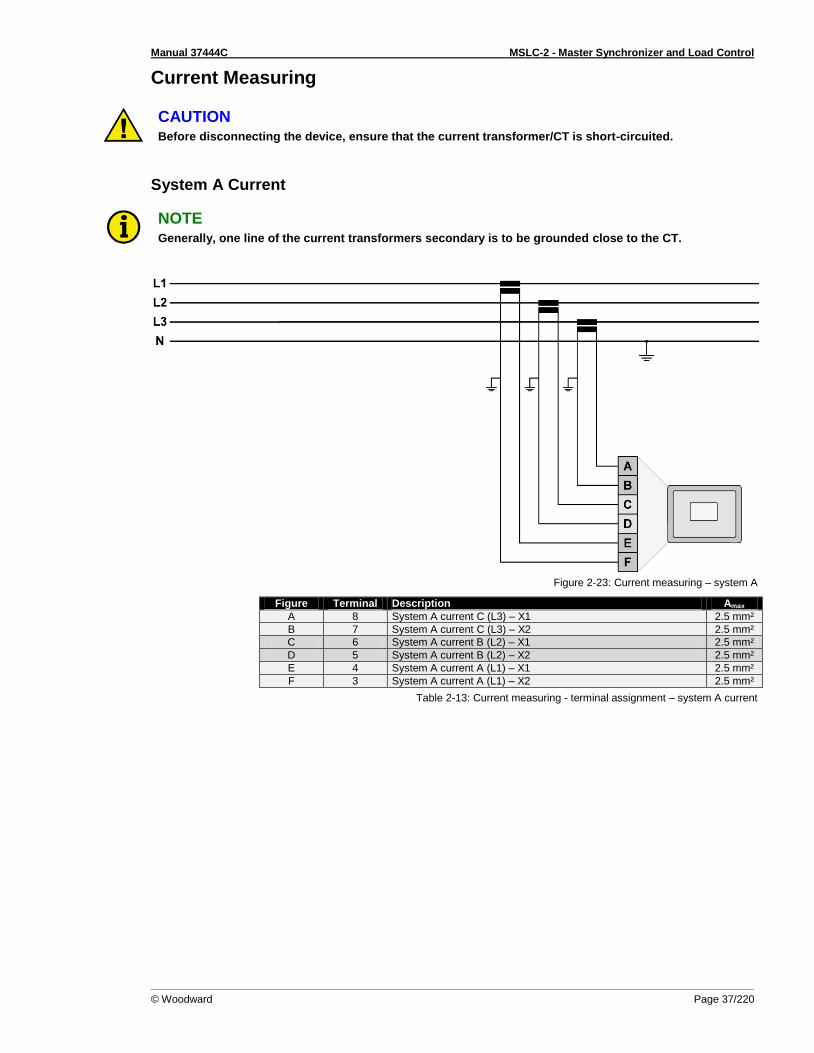
Manual 37444C MSLC-2 - Master Synchronizer and Load Control
© Woodward Page 37/220
Current Measuring
CAUTION Before disconnecting the device, ensure that the current transformer/CT is short-circuited.
System A Current
NOTE Generally, one line of the current transformers secondary is to be grounded close to the CT.
Figure 2-23: Current measuring – system A
Figure Terminal Description Amax
A 8 System A current C (L3) – X1 2.5 mm²
B 7 System A current C (L3) – X2 2.5 mm²
C 6 System A current B (L2) – X1 2.5 mm²
D 5 System A current B (L2) – X2 2.5 mm²
E 4 System A current A (L1) – X1 2.5 mm²
F 3 System A current A (L1) – X2 2.5 mm²
Table 2-13: Current measuring - terminal assignment – system A current
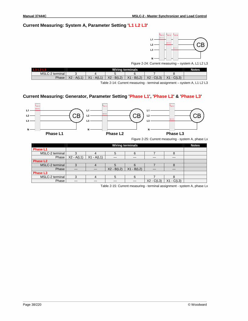
Manual 37444C MSLC-2 - Master Synchronizer and Load Control
Page 38/220 © Woodward
Current Measuring: System A, Parameter Setting 'L1 L2 L3'
Figure 2-24: Current measuring – system A, L1 L2 L3
L1 L2 L3 Wiring terminals Notes
MSLC-2 terminal 3 4 5 6 7 8
Phase X2 - A(L1) X1 - A(L1) X2 - B(L2) X1 - B(L2) X2 - C(L3) X1 - C(L3)
Table 2-14: Current measuring - terminal assignment – system A, L1 L2 L3
Current Measuring: Generator, Parameter Setting 'Phase L1', 'Phase L2' & 'Phase L3'
Phase L1 Phase L2 Phase L3
Figure 2-25: Current measuring - system A, phase Lx
Wiring terminals Notes
Phase L1
MSLC-2 terminal 3 4 5 6 7 8
Phase X2 - A(L1) X1 - A(L1) --- --- --- ---
Phase L2
MSLC-2 terminal 3 4 5 6 7 8
Phase --- --- X2 - B(L2) X1 - B(L2) --- ---
Phase L3
MSLC-2 terminal 3 4 5 6 7 8
Phase --- --- --- --- X2 - C(L3) X1 - C(L3)
Table 2-15: Current measuring - terminal assignment - system A, phase Lx
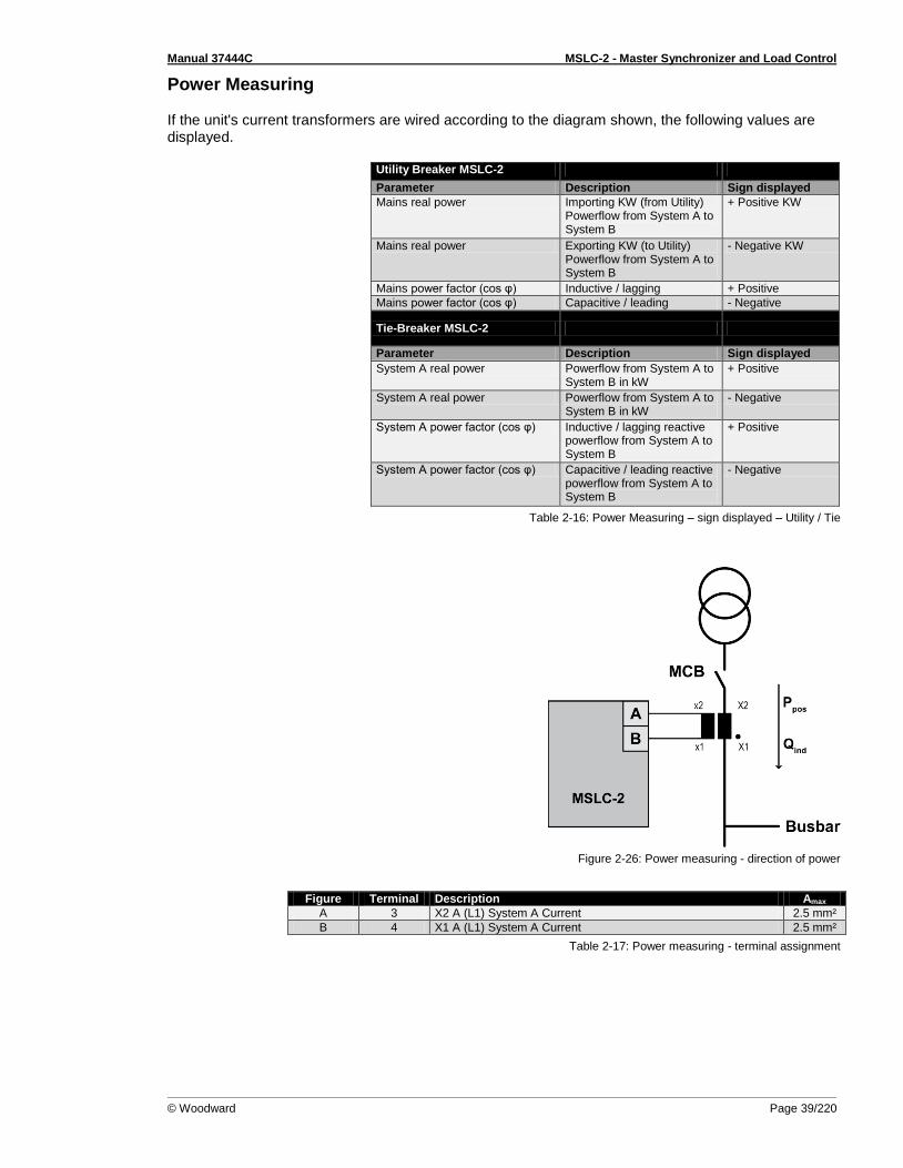
Manual 37444C MSLC-2 - Master Synchronizer and Load Control
© Woodward Page 39/220
Power Measuring If the unit's current transformers are wired according to the diagram shown, the following values are displayed.
Utility Breaker MSLC-2
Parameter Description Sign displayed
Mains real power Importing KW (from Utility) Powerflow from System A to System B
+ Positive KW
Mains real power Exporting KW (to Utility) Powerflow from System A to System B
- Negative KW
Mains power factor (cos φ) Inductive / lagging + Positive
Mains power factor (cos φ) Capacitive / leading - Negative
Tie-Breaker MSLC-2
Parameter Description Sign displayed
System A real power Powerflow from System A to System B in kW
+ Positive
System A real power Powerflow from System A to System B in kW
- Negative
System A power factor (cos φ) Inductive / lagging reactive powerflow from System A to System B
+ Positive
System A power factor (cos φ) Capacitive / leading reactive powerflow from System A to System B
- Negative
Table 2-16: Power Measuring – sign displayed – Utility / Tie
Figure 2-26: Power measuring - direction of power
Figure Terminal Description Amax
A 3 X2 A (L1) System A Current 2.5 mm²
B 4 X1 A (L1) System A Current 2.5 mm²
Table 2-17: Power measuring - terminal assignment
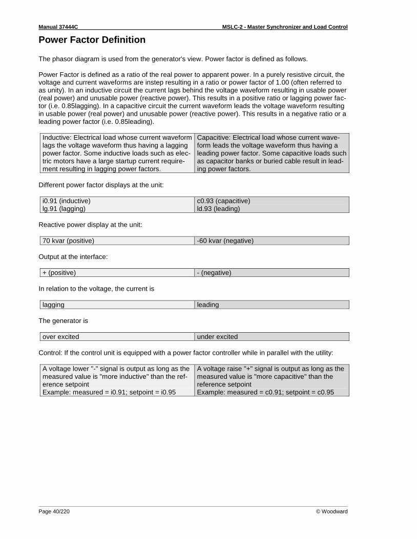
Manual 37444C MSLC-2 - Master Synchronizer and Load Control
Page 40/220 © Woodward
Power Factor Definition The phasor diagram is used from the generator's view. Power factor is defined as follows. Power Factor is defined as a ratio of the real power to apparent power. In a purely resistive circuit, the voltage and current waveforms are instep resulting in a ratio or power factor of 1.00 (often referred to as unity). In an inductive circuit the current lags behind the voltage waveform resulting in usable power (real power) and unusable power (reactive power). This results in a positive ratio or lagging power fac-tor (i.e. 0.85lagging). In a capacitive circuit the current waveform leads the voltage waveform resulting in usable power (real power) and unusable power (reactive power). This results in a negative ratio or a leading power factor (i.e. 0.85leading).
Inductive: Electrical load whose current waveform lags the voltage waveform thus having a lagging power factor. Some inductive loads such as elec-tric motors have a large startup current require-ment resulting in lagging power factors.
Capacitive: Electrical load whose current wave-form leads the voltage waveform thus having a leading power factor. Some capacitive loads such as capacitor banks or buried cable result in lead-ing power factors.
Different power factor displays at the unit:
i0.91 (inductive) lg.91 (lagging)
c0.93 (capacitive) ld.93 (leading)
Reactive power display at the unit:
70 kvar (positive) -60 kvar (negative)
Output at the interface:
+ (positive) - (negative)
In relation to the voltage, the current is
lagging leading
The generator is
over excited under excited
Control: If the control unit is equipped with a power factor controller while in parallel with the utility:
A voltage lower "-" signal is output as long as the measured value is "more inductive" than the ref-erence setpoint Example: measured = i0.91; setpoint = i0.95
A voltage raise "+" signal is output as long as the measured value is "more capacitive" than the reference setpoint Example: measured = c0.91; setpoint = c0.95

Manual 37444C MSLC-2 - Master Synchronizer and Load Control
© Woodward Page 41/220
Phasor diagram:
inductive capacitive
Figure 2-27: Phasor diagram – inductive / capacitive
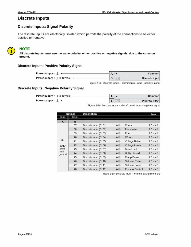
Manual 37444C MSLC-2 - Master Synchronizer and Load Control
Page 42/220 © Woodward
Discrete Inputs
Discrete Inputs: Signal Polarity The discrete inputs are electrically isolated which permits the polarity of the connections to be either positive or negative.
NOTE All discrete inputs must use the same polarity, either positive or negative signals, due to the common ground.
Discrete Inputs: Positive Polarity Signal
Figure 2-28: Discrete inputs - alarm/control input - positive signal
Discrete Inputs: Negative Polarity Signal
Figure 2-29: Discrete inputs - alarm/control input - negative signal
Terminal Description Amax
Term. Com.
A B
66
GND com-mon
ground
67 Discrete input [DI 01] all Check 2.5 mm²
68 Discrete input [DI 02] all Permissive 2.5 mm²
69 Discrete input [DI 03] all Run 2.5 mm²
70 Discrete input [DI 04] all CB Aux 2.5 mm²
71 Discrete input [DI 05] all Voltage Raise 2.5 mm²
72 Discrete input [DI 06] all Voltage Lower 2.5 mm²
73 Discrete input [DI 07] all Base Load 2.5 mm²
74 Discrete input [DI 08] all Utility Unload 2.5 mm²
75 Discrete input [DI 09] all Ramp Pause 2.5 mm²
76 Discrete input [DI 10] all Setpoint Raise 2.5 mm²
77 Discrete input [DI 11] all Setpoint Lower 2.5 mm²
78 Discrete input [DI 12] all Process Control 2.5 mm²
Table 2-18: Discrete input - terminal assignment 1/2
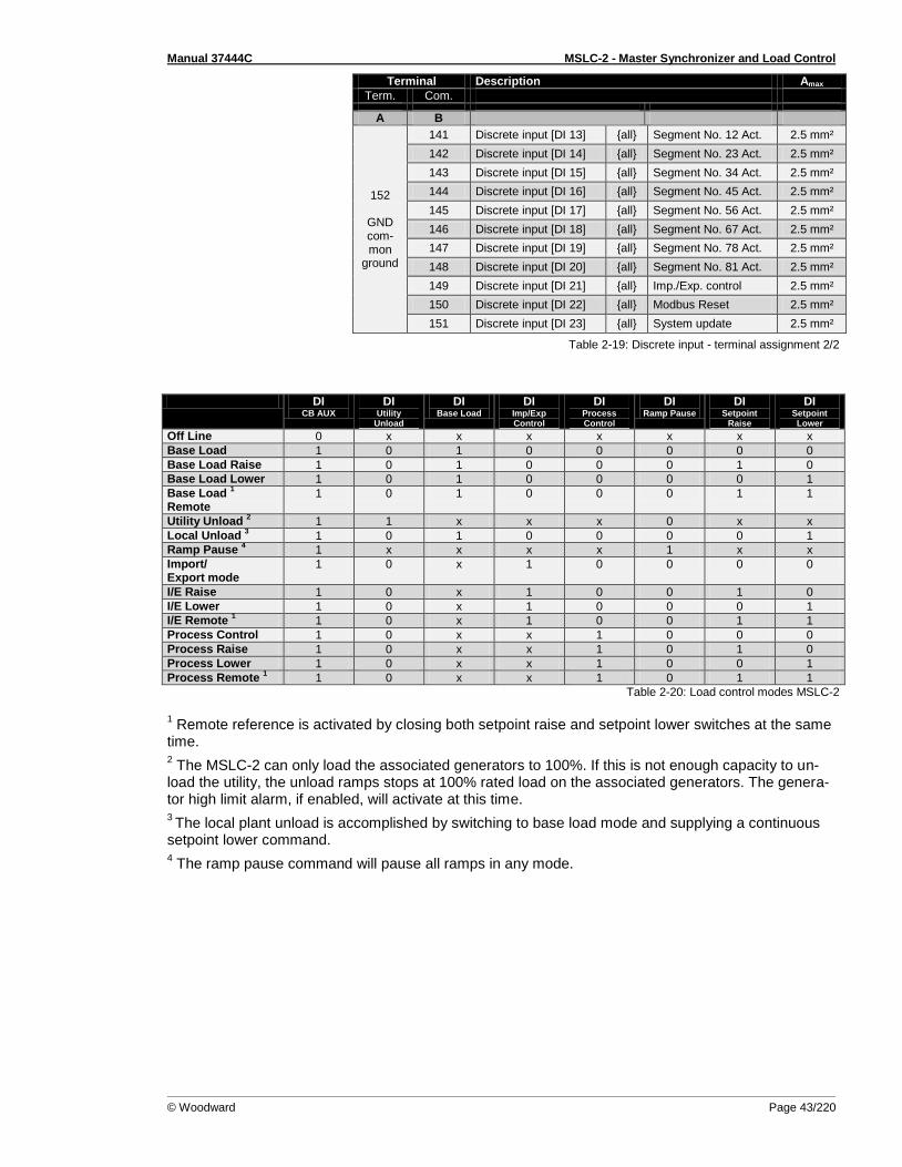
Manual 37444C MSLC-2 - Master Synchronizer and Load Control
© Woodward Page 43/220
Terminal Description Amax
Term. Com.
A B
152
GND com-mon
ground
141 Discrete input [DI 13] all Segment No. 12 Act. 2.5 mm²
142 Discrete input [DI 14] all Segment No. 23 Act. 2.5 mm²
143 Discrete input [DI 15] all Segment No. 34 Act. 2.5 mm²
144 Discrete input [DI 16] all Segment No. 45 Act. 2.5 mm²
145 Discrete input [DI 17] all Segment No. 56 Act. 2.5 mm²
146 Discrete input [DI 18] all Segment No. 67 Act. 2.5 mm²
147 Discrete input [DI 19] all Segment No. 78 Act. 2.5 mm²
148 Discrete input [DI 20] all Segment No. 81 Act. 2.5 mm²
149 Discrete input [DI 21] all Imp./Exp. control 2.5 mm²
150 Discrete input [DI 22] all Modbus Reset 2.5 mm²
151 Discrete input [DI 23] all System update 2.5 mm²
Table 2-19: Discrete input - terminal assignment 2/2
DI CB AUX
DI Utility
Unload
DI Base Load
DI Imp/Exp Control
DI Process Control
DI Ramp Pause
DI Setpoint
Raise
DI Setpoint Lower
Off Line 0 x x x x x x x
Base Load 1 0 1 0 0 0 0 0
Base Load Raise 1 0 1 0 0 0 1 0
Base Load Lower 1 0 1 0 0 0 0 1
Base Load 1
Remote 1 0 1 0 0 0 1 1
Utility Unload 2 1 1 x x x 0 x x
Local Unload 3 1 0 1 0 0 0 0 1
Ramp Pause 4 1 x x x x 1 x x
Import/ Export mode
1 0 x 1 0 0 0 0
I/E Raise 1 0 x 1 0 0 1 0
I/E Lower 1 0 x 1 0 0 0 1
I/E Remote 1 1 0 x 1 0 0 1 1
Process Control 1 0 x x 1 0 0 0
Process Raise 1 0 x x 1 0 1 0
Process Lower 1 0 x x 1 0 0 1
Process Remote 1 1 0 x x 1 0 1 1
Table 2-20: Load control modes MSLC-2
1 Remote reference is activated by closing both setpoint raise and setpoint lower switches at the same
time.
2 The MSLC-2 can only load the associated generators to 100%. If this is not enough capacity to un-
load the utility, the unload ramps stops at 100% rated load on the associated generators. The genera-tor high limit alarm, if enabled, will activate at this time.
3 The local plant unload is accomplished by switching to base load mode and supplying a continuous
setpoint lower command.
4 The ramp pause command will pause all ramps in any mode.

Manual 37444C MSLC-2 - Master Synchronizer and Load Control
Page 44/220 © Woodward
Relay Outputs
Figure 2-30: Relay outputs
Terminal Description Amax
Term. Com.
A B Form A, N.O. make contact Type
42 41 Relay output [R 01] all Alarm (Self Test OK) N.O. 2.5 mm²
43
46
Relay output [R 02] all Reserve N.O. 2.5 mm²
44 Relay output [R 03] all High Limit N.O. 2.5 mm²
45 Relay output [R 04] all Low Limit N.O. 2.5 mm²
48 47 Relay output [R 05] all Breaker Open N.O. 2.5 mm²
50 49 Relay output [R 06] all Breaker Close N.O. 2.5 mm²
52 51 Relay output [R 07] all Lcl./Gen. Breaker Open N.O. 2.5 mm²
54 53 Relay output [R 08] all Alarm 1 / Freq. Raise N.O. 2.5 mm²
56 55 Relay output [R 09] all Alarm 2 / Freq. Lower N.O. 2.5 mm²
57
60
Relay output [R 10] all Alarm 3 N.O. 2.5 mm²
58 Relay output [R 11] all Load Switch 1 N.O. 2.5 mm²
59 Relay output [R 12] all Load Switch 2 N.O. 2.5 mm²
N.O.-normally open (make) contact
Table 2-21: Relay outputs - terminal assignment
CAUTION The discrete output "Alarm (Self Test OK)" can be wired in series with an emergency stop function. This means that it must be ensured that the generator circuit breaker can be opened, if this discrete output is de-energized. We recommend signaling this fault independently from the unit if the availabil-ity of the plant is important.
NOTE Alarms 1, 2, and 3 can be used for monitoring only.
Don’t use alarm messages for protection control!

Manual 37444C MSLC-2 - Master Synchronizer and Load Control
© Woodward Page 45/220
DO Alarm
DO Reserve
DO High Limit
DO Low Limit
DO Breaker
Open
DO Breaker Close
DO LCL/ Gen
Breaker Open
DO Alarm 1
DO Alarm 2
DO Alarm 3
DO Load
switch 1
DO Load
switch 2
Self Test x
Reserve x
High load limit
x High process limit
High voltage limit
Low load limit
x Low process limit
Low voltage limit
Utility Unload (DI 8)
x
Synchronization deadbus closure
x
Local Generator Breaker open (DI 11)
x
Synchronizer timeout
x x x
Reclose limit
High load limit
Low load limit
High process limit
Low process limit
Low voltage limit
High voltage limit
Voltage range limit
Communication error
Missing member
Centralized alarm
CB open fail
Deadbus closure mismatch
System B mis-match
Rotation mis-match
Load switch 1 x
Load switch 2 x
Table 2-22: Relay outputs driven by …
NOTE Refer to Appendix D: Connecting 24 V Relays on page 195 for interference suppressing circuits when connecting 24 V relays.

Manual 37444C MSLC-2 - Master Synchronizer and Load Control
Page 46/220 © Woodward
Analog Inputs The following senders may be used for the analog inputs:
0 to 20mA
4 to 20mA
0 to 10V
0 to 5V
1 to 5V
Wiring Examples
Figure 2-31: Analog inputs - wiring two-pole senders using a voltage signal
Figure 2-32: Analog inputs - wiring two-pole senders (external jumper used for current signal)
Figure Terminal Description Amax
A 83 Analog input [AI 01] Remote Load Reference Input
2.5 mm²
B 84 2.5 mm²
C 85 + 2.5 mm²
A 86 Analog input [AI 02] Process Signal Input
2.5 mm²
B 87 2.5 mm²
C 88 + 2.5 mm²
A 89 Analog input [AI 03] Reactive Load Input
2.5 mm²
B 90 2.5 mm²
C 91 + 2.5 mm²
Table 2-23: Analog inputs - terminal assignment - wiring two-pole senders
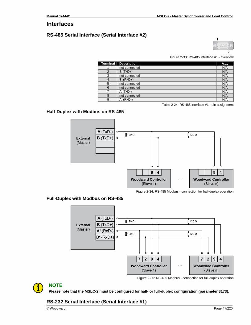
Manual 37444C MSLC-2 - Master Synchronizer and Load Control
© Woodward Page 47/220
Interfaces
RS-485 Serial Interface (Serial Interface #2)
Figure 2-33: RS-485 interface #1 - overview
Terminal Description Amax
1 not connected N/A
2 B (TxD+) N/A
3 not connected N/A
4 B' (RxD+) N/A
5 not connected N/A
6 not connected N/A
7 A (TxD-) N/A
8 not connected N/A
9 A' (RxD-) N/A
Table 2-24: RS-485 interface #1 - pin assignment
Half-Duplex with Modbus on RS-485
Figure 2-34: RS-485 Modbus - connection for half-duplex operation
Full-Duplex with Modbus on RS-485
Figure 2-35: RS-485 Modbus - connection for full-duplex operation
NOTE Please note that the MSLC-2 must be configured for half- or full-duplex configuration (parameter 3173).
RS-232 Serial Interface (Serial Interface #1)
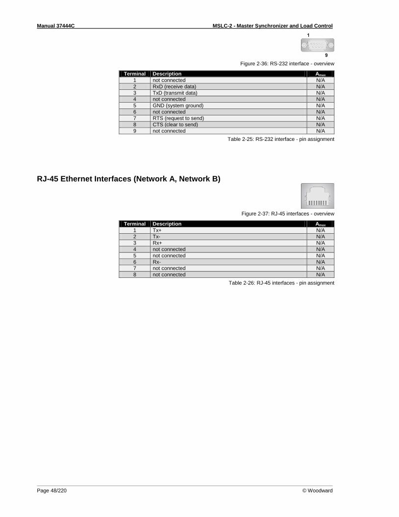
Manual 37444C MSLC-2 - Master Synchronizer and Load Control
Page 48/220 © Woodward
Figure 2-36: RS-232 interface - overview
Terminal Description Amax
1 not connected N/A
2 RxD (receive data) N/A
3 TxD (transmit data) N/A
4 not connected N/A
5 GND (system ground) N/A
6 not connected N/A
7 RTS (request to send) N/A
8 CTS (clear to send) N/A
9 not connected N/A
Table 2-25: RS-232 interface - pin assignment
RJ-45 Ethernet Interfaces (Network A, Network B)
Figure 2-37: RJ-45 interfaces - overview
Terminal Description Amax
1 Tx+ N/A
2 Tx- N/A
3 Rx+ N/A
4 not connected N/A
5 not connected N/A
6 Rx- N/A
7 not connected N/A
8 not connected N/A
Table 2-26: RJ-45 interfaces - pin assignment
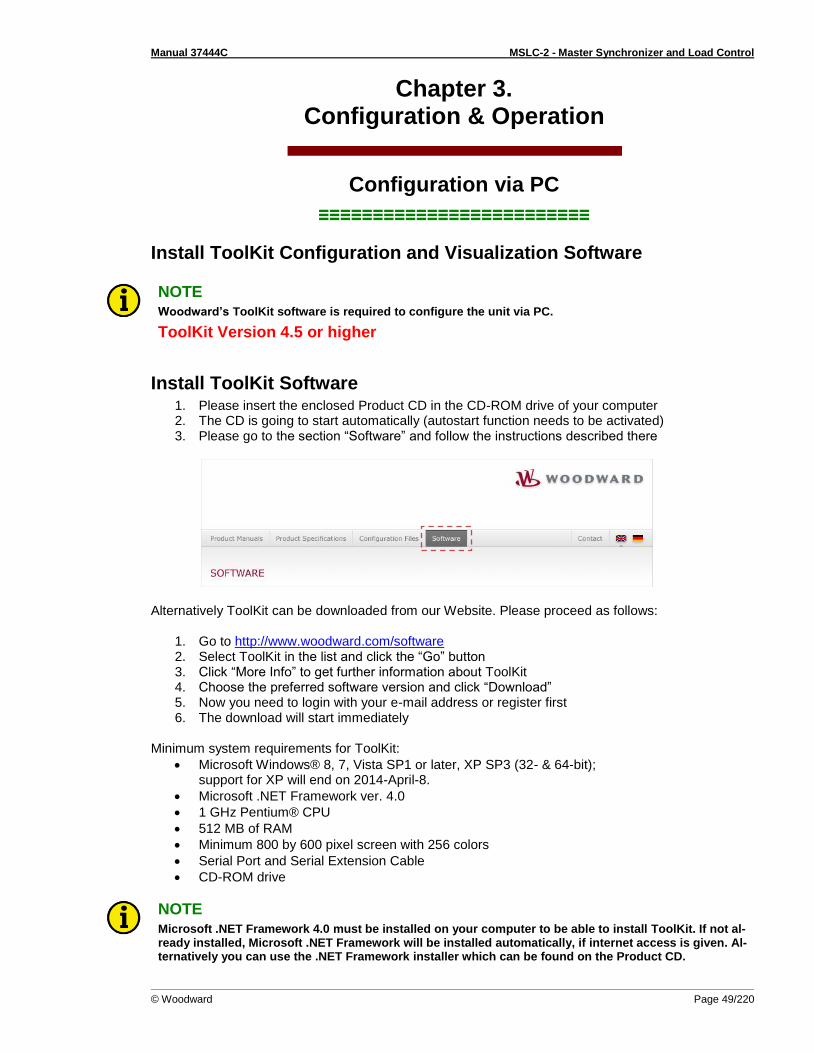
Manual 37444C MSLC-2 - Master Synchronizer and Load Control
© Woodward Page 49/220
Chapter 3. Configuration & Operation
Configuration via PC
≡≡≡≡≡≡≡≡≡≡≡≡≡≡≡≡≡≡≡≡≡≡≡≡≡
Install ToolKit Configuration and Visualization Software
NOTE Woodward’s ToolKit software is required to configure the unit via PC.
ToolKit Version 4.5 or higher
Install ToolKit Software 1. Please insert the enclosed Product CD in the CD-ROM drive of your computer 2. The CD is going to start automatically (autostart function needs to be activated) 3. Please go to the section “Software” and follow the instructions described there
Alternatively ToolKit can be downloaded from our Website. Please proceed as follows:
1. Go to http://www.woodward.com/software 2. Select ToolKit in the list and click the “Go” button 3. Click “More Info” to get further information about ToolKit 4. Choose the preferred software version and click “Download” 5. Now you need to login with your e-mail address or register first 6. The download will start immediately
Minimum system requirements for ToolKit:
Microsoft Windows® 8, 7, Vista SP1 or later, XP SP3 (32- & 64-bit); support for XP will end on 2014-April-8.
Microsoft .NET Framework ver. 4.0
1 GHz Pentium® CPU
512 MB of RAM
Minimum 800 by 600 pixel screen with 256 colors
Serial Port and Serial Extension Cable
CD-ROM drive
NOTE Microsoft .NET Framework 4.0 must be installed on your computer to be able to install ToolKit. If not al-ready installed, Microsoft .NET Framework will be installed automatically, if internet access is given. Al-ternatively you can use the .NET Framework installer which can be found on the Product CD.
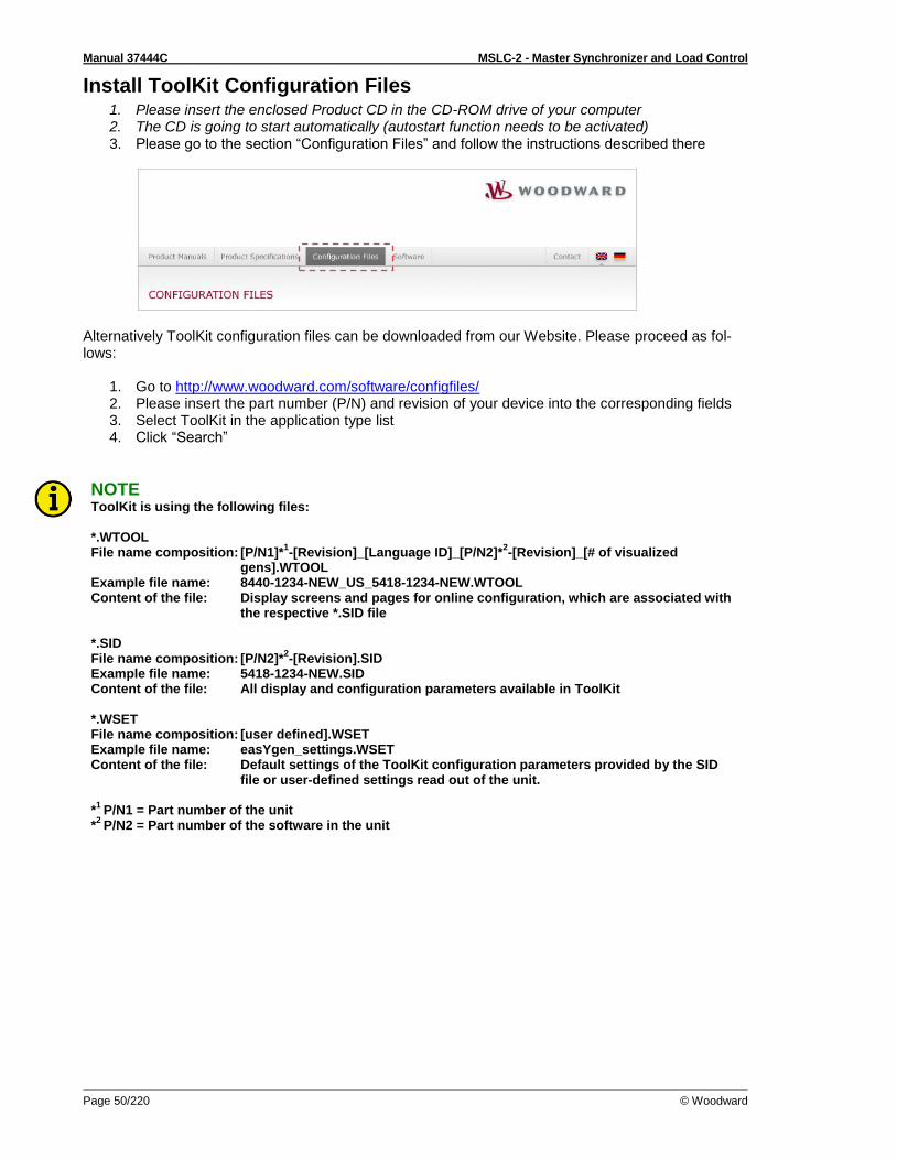
Manual 37444C MSLC-2 - Master Synchronizer and Load Control
Page 50/220 © Woodward
Install ToolKit Configuration Files 1. Please insert the enclosed Product CD in the CD-ROM drive of your computer 2. The CD is going to start automatically (autostart function needs to be activated) 3. Please go to the section “Configuration Files” and follow the instructions described there
Alternatively ToolKit configuration files can be downloaded from our Website. Please proceed as fol-lows:
1. Go to http://www.woodward.com/software/configfiles/ 2. Please insert the part number (P/N) and revision of your device into the corresponding fields 3. Select ToolKit in the application type list 4. Click “Search”
NOTE ToolKit is using the following files: *.WTOOL File name composition: [P/N1]*
1-[Revision]_[Language ID]_[P/N2]*
2-[Revision]_[# of visualized
gens].WTOOL Example file name: 8440-1234-NEW_US_5418-1234-NEW.WTOOL Content of the file: Display screens and pages for online configuration, which are associated with
the respective *.SID file *.SID File name composition: [P/N2]*
2-[Revision].SID
Example file name: 5418-1234-NEW.SID Content of the file: All display and configuration parameters available in ToolKit *.WSET File name composition: [user defined].WSET Example file name: easYgen_settings.WSET Content of the file: Default settings of the ToolKit configuration parameters provided by the SID
file or user-defined settings read out of the unit. *
1 P/N1 = Part number of the unit
*2
P/N2 = Part number of the software in the unit
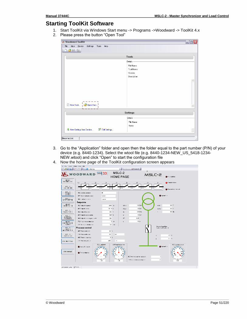
Manual 37444C MSLC-2 - Master Synchronizer and Load Control
© Woodward Page 51/220
Starting ToolKit Software 1. Start ToolKit via Windows Start menu -> Programs ->Woodward -> ToolKit 4.x 2. Please press the button “Open Tool”
3. Go to the “Application” folder and open then the folder equal to the part number (P/N) of your device (e.g. 8440-1234). Select the wtool file (e.g. 8440-1234-NEW_US_5418-1234-NEW.wtool) and click “Open” to start the configuration file
4. Now the home page of the ToolKit configuration screen appears

Manual 37444C MSLC-2 - Master Synchronizer and Load Control
Page 52/220 © Woodward
Configure ToolKit Software 1. Start the configuration by using the toolbar. Please go to Tools -> Options
2. The options window will be displayed
a. Adjust the default locations of the configuration files b. The displayed language can be selected here
3. The changes become effective after clicking “OK”
NOTE Please use the ToolKit online help for further information.
b
a
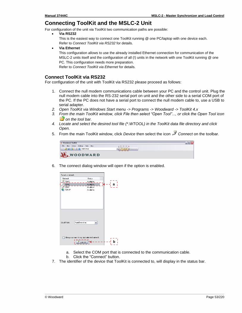
Manual 37444C MSLC-2 - Master Synchronizer and Load Control
© Woodward Page 53/220
Connecting ToolKit and the MSLC-2 Unit For configuration of the unit via ToolKit two communication paths are possible:
Via RS232
This is the easiest way to connect one ToolKit running @ one PC/laptop with one device each.
Refer to Connect ToolKit via RS232 for details.
Via Ethernet
This configuration allows to use the already installed Ethernet connection for communication of the
MSLC-2 units itself and the configuration of all (!) units in the network with one ToolKit running @ one
PC. This configuration needs more preparation.
Refer to Connect ToolKit via Ethernet for details.
Connect ToolKit via RS232 For configuration of the unit with ToolKit via RS232 please proceed as follows:
1. Connect the null modem communications cable between your PC and the control unit. Plug the null modem cable into the RS-232 serial port on unit and the other side to a serial COM port of the PC. If the PC does not have a serial port to connect the null modem cable to, use a USB to serial adapter.
2. Open ToolKit via Windows Start menu -> Programs -> Woodward -> ToolKit 4.x 3. From the main ToolKit window, click File then select “Open Tool”..., or click the Open Tool icon
on the tool bar. 4. Locate and select the desired tool file (*.WTOOL) in the ToolKit data file directory and click
Open.
5. From the main ToolKit window, click Device then select the icon Connect on the toolbar.
6. The connect dialog window will open if the option is enabled.
a. Select the COM port that is connected to the communication cable. b. Click the “Connect” button.
7. The identifier of the device that ToolKit is connected to, will display in the status bar.
b
a

Manual 37444C MSLC-2 - Master Synchronizer and Load Control
Page 54/220 © Woodward
8. If the Communications window opens, select “ToolConfigurator” under Tool Device and close the Communications window.
9. If the device is security enabled, the Login dialog will appear. 10. Enter password. 11. Now you are able to edit the MSLC-2 parameters in the main window. Any changes made are
written to the control memory automatically.
Connect ToolKit via Ethernet
NOTE
It is recommended to connect ToolKit via Network A. Firewall settings must allow ToolKit to interact.
For configuration of the unit via ToolKit please proceed as follows:
1. Connect your PC and the control unit via the Ethernet communications cable. 2. Open ToolKit via Windows Start menu -> Programs -> Woodward -> ToolKit 4.x 3. From the main ToolKit window, click File then select “Open Tool”... or click the Open Tool icon
on the tool bar. 4. Locate and select the desired tool file (*.WTOOL) in the ToolKit data file directory and click
Open.
5. From the main ToolKit window, click the icon Connect on the toolbar.
The connect dialog window will open if the option is enabled.
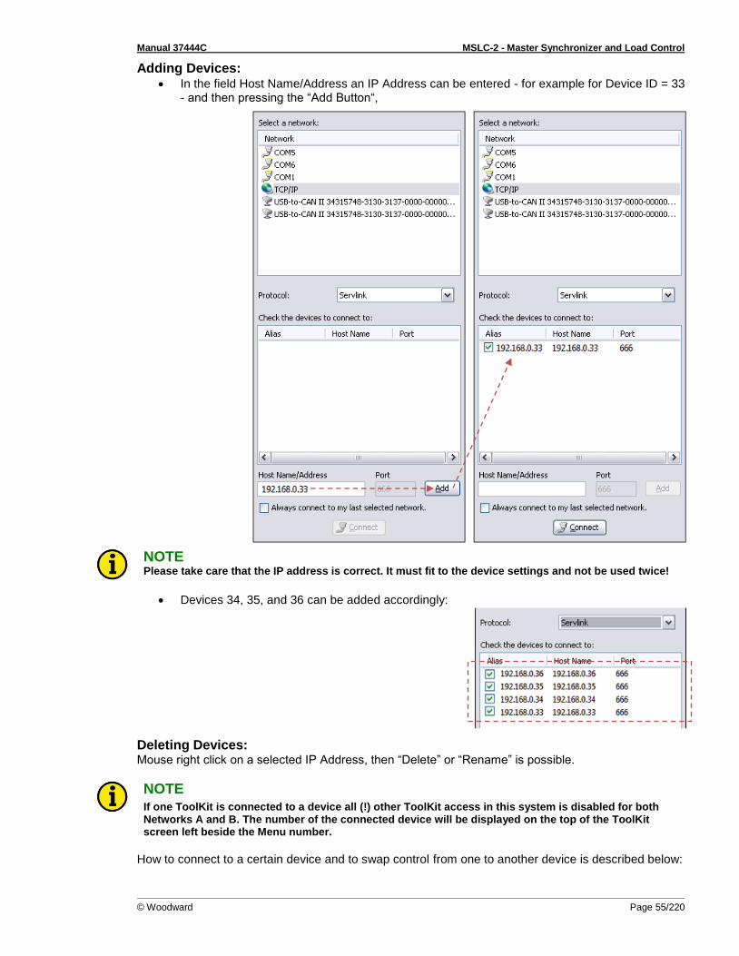
Manual 37444C MSLC-2 - Master Synchronizer and Load Control
© Woodward Page 55/220
Adding Devices: In the field Host Name/Address an IP Address can be entered - for example for Device ID = 33
- and then pressing the “Add Button“,
NOTE Please take care that the IP address is correct. It must fit to the device settings and not be used twice!
Devices 34, 35, and 36 can be added accordingly:
Deleting Devices: Mouse right click on a selected IP Address, then “Delete” or “Rename” is possible.
NOTE If one ToolKit is connected to a device all (!) other ToolKit access in this system is disabled for both Networks A and B. The number of the connected device will be displayed on the top of the ToolKit screen left beside the Menu number.
How to connect to a certain device and to swap control from one to another device is described below:

Manual 37444C MSLC-2 - Master Synchronizer and Load Control
Page 56/220 © Woodward
Selecting devices for ToolKit communication Click on “Connect”:
Click on „Details“:
In row of device 35 click on <None> pull-down button and select „ToolConfigurator“:
Device 35 is selected:
To select another device e.g., device 37, first deselect device 35: In row of device 35 click on < ToolConfigurator> pull-down button and select „ None “
Than in row of device 37 click on <None> pull-down button and select „ToolConfigurator“ as described above. Selection works with one of the connected devices so deselect the other first!
NOTE The Device ID is important for system management. Device ID and/or other IP address mis-match can cause reduced functionality of missing member alarm or even loss of control. Use System update (parameter 7789) for changing device ID! See chapter on page for more details.
NOTE Device access always is depending on the device’s current password level. Be aware of each device‘s password level—especially if connecting to several devices as described above! E.g., loading .wset files is depending on the password level. Only parameters with the device’s current password level or lower will be loaded: Different password levels = different load results!
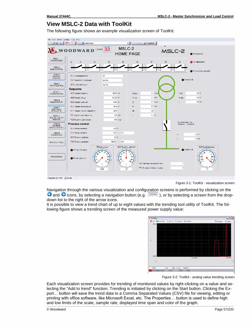
Manual 37444C MSLC-2 - Master Synchronizer and Load Control
© Woodward Page 57/220
View MSLC-2 Data with ToolKit The following figure shows an example visualization screen of ToolKit:
Figure 3-1: ToolKit - visualization screen
Navigation through the various visualization and configuration screens is performed by clicking on the
and icons, by selecting a navigation button (e.g. ), or by selecting a screen from the drop-down list to the right of the arrow icons. It is possible to view a trend chart of up to eight values with the trending tool utility of ToolKit. The fol-lowing figure shows a trending screen of the measured power supply value:
Figure 3-2: ToolKit - analog value trending screen
Each visualization screen provides for trending of monitored values by right-clicking on a value and se-lecting the "Add to trend" function. Trending is initiated by clicking on the Start button. Clicking the Ex-port… button will save the trend data to a Comma Separated Values (CSV) file for viewing, editing or printing with office software, like Microsoft Excel, etc. The Properties… button is used to define high and low limits of the scale, sample rate, displayed time span and color of the graph.
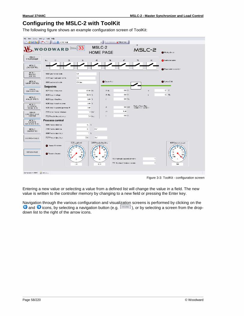
Manual 37444C MSLC-2 - Master Synchronizer and Load Control
Page 58/220 © Woodward
Configuring the MSLC-2 with ToolKit The following figure shows an example configuration screen of ToolKit:
Figure 3-3: ToolKit - configuration screen
Entering a new value or selecting a value from a defined list will change the value in a field. The new value is written to the controller memory by changing to a new field or pressing the Enter key. Navigation through the various configuration and visualization screens is performed by clicking on the
and icons, by selecting a navigation button (e.g. ), or by selecting a screen from the drop-down list to the right of the arrow icons.

Manual 37444C MSLC-2 - Master Synchronizer and Load Control
© Woodward Page 59/220
The MSLC-2 Version Page The ToolKit version page allows you to check the serial number of the unit and versions of the bootloader, operating system and GAP application.
Figure 3-4: ToolKit -version page
NOTE Flashing a device with another firmware is restricted to Woodward personnel only! It is possible to flash release 2 firmware into already existing release 1 hardware but via RS232 interface only. Please contact your local Woodward partner for support.

Manual 37444C MSLC-2 - Master Synchronizer and Load Control
Page 60/220 © Woodward
Menu (Setpoint) Description
≡≡≡≡≡≡≡≡≡≡≡≡≡≡≡≡≡≡≡≡≡≡≡≡≡ All parameters are assigned a unique parameter identification number (ID). The parameter identifica-tion number may be used to reference individual parameters listed in this manual. This parameter iden-tification number is also displayed in the ToolKit configuration screens next to the respective parame-ter.
MSLC-2 – Homepage The appearance of the MSLC-2 Homepage depends on the configuration. If the MSLC-2 type is con-figured as “Utility” MSLC-2 (parameter 7628), values and pictures are displayed in the sense being lo-cated at the utility. On the other side, the “Tie” configured MSLC-2 shows values and pictures related to a tie-breaker sense. This is the basic page of the MSLC-2. It gives general information, such as:
• The system A condition • The system B (busbar) condition • The condition of the breaker • The current operating action • The load and reactive load output to the DSLC-2 • The segment breaker state
Figure 3-5: ToolKit - home page (MSLC-2 configured as utility breaker control)
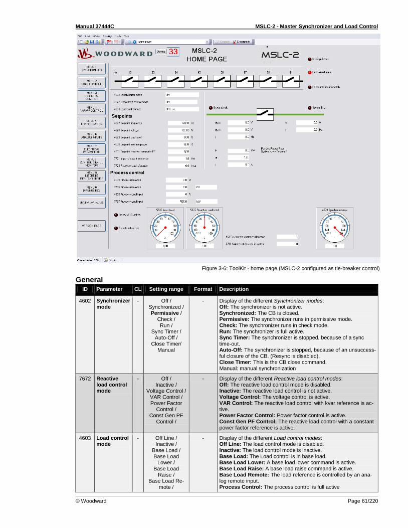
Manual 37444C MSLC-2 - Master Synchronizer and Load Control
© Woodward Page 61/220
Figure 3-6: ToolKit - home page (MSLC-2 configured as tie-breaker control)
General
ID Parameter CL Setting range Format Description
4602 Synchronizer mode
- Off / Synchronized / Permissive /
Check / Run /
Sync Timer / Auto-Off /
Close Timer/ Manual
- Display of the different Synchronizer modes: Off: The synchronizer is not active. Synchronized: The CB is closed. Permissive: The synchronizer runs in permissive mode. Check: The synchronizer runs in check mode. Run: The synchronizer is full active. Sync Timer: The synchronizer is stopped, because of a sync time-out. Auto-Off: The synchronizer is stopped, because of an unsuccess-ful closure of the CB. (Resync is disabled). Close Timer: This is the CB close command. Manual: manual synchronization
7672 Reactive load control mode
- Off / Inactive /
Voltage Control / VAR Control / Power Factor
Control / Const Gen PF
Control /
- Display of the different Reactive load control modes: Off: The reactive load control mode is disabled. Inactive: The reactive load control is not active. Voltage Control: The voltage control is active. VAR Control: The reactive load control with kvar reference is ac-tive. Power Factor Control: Power factor control is active. Const Gen PF Control: The reactive load control with a constant power factor reference is active.
4603 Load control mode
- Off Line / Inactive /
Base Load / Base Load
Lower / Base Load
Raise / Base Load Re-
mote /
- Display of the different Load control modes: Off Line: The load control mode is disabled. Inactive: The load control mode is inactive. Base Load: The Load control is in base load. Base Load Lower: A base load lower command is active. Base Load Raise: A base load raise command is active. Base Load Remote: The load reference is controlled by an ana-log remote input. Process Control: The process control is full active

Manual 37444C MSLC-2 - Master Synchronizer and Load Control
Page 62/220 © Woodward
ID Parameter CL Setting range Format Description
Process Control / Process Lower / Process Raise /
Process Remote /
Process Ramp / Import Export
Control / Import Export
Ramp / Import Export
Remote / Imp Exp Lower / Imp Exp Raise /
Utility Unload
Process Lower: A process reference lower command is active. Process Raise: A process reference raise command is active. Process Remote: The process reference is controlled by an ana-log remote input Process Ramp: The generators are ramped into process control Import Export Control: The Import Export control is active. Import Export Ramp: The generators are being ramped into Im / Ex control Import Export Remote: The Import Export reference is controlled by an analog remote input Imp Exp Lower: An Import Export lower command is active. Imp Exp Raise: An Import Export raise command is active. Utility Unload: The utility or tie-breaker is being unloaded.
Table 3-7: Parameter – homepage - General
Setpoints
ID Parameter CL Setting range Format Description
4627 Setpoint frequency
- Info 0.00 Hz The field indicates the current Setpoint Frequency in Hz.
4628 Setpoint voltage
- Info 0.00% The field indicates the current Setpoint Voltage in percentage.
4629 Setpoint load level
- Info 0.00% Indicates the load level setpoint in percentage.
4630 Setpoint re-active power
- Info 0.00% Indicates the reactive load level setpoint in percentage.
4631 Setpoint constant generator PF
- Info 0.00 The field indicates the constant generator power factor setpoint sent to the DSLC-2. NOTE: This field only indicates values if “VAR PF control mode” (parameter 7558) is configured to “Constant Generator PF”.
7721 Import / export reference
Info 0.0 kW The field indicates the current import / export setpoint for the MSLC-2 in kW.
7722 Reactive load reference
- Info 0.0 kvar The field indicates the current reactive load setpoint for the MSLC-2 in kvar.
Table 3-8: Parameter – homepage - Setpoints
Process control
ID Parameter CL Setting range Format Description
4605 Process reference
- Info 0.0% The field indicates the current Process reference value of the MSLC-2 process control in percentage.
7726 Process reference
- Info 0.0 kW The field indicates the current Process reference value of the MSLC-2 process control in engineering units.
4600 Process signal input
- Info 0.0% The field indicates the real Process signal input value of the MSLC-2 process control in percentage.
7727 Process signal input
- Info 0.0 kW The field indicates the real Process signal input value of the MSLC-2 process control in engineering units.
5535 Load level Info 0.00% The gage indicates the load setpoint going to the DSLC-2.
5635 Reactive load level
Info 0.00% The gage indicates the reactive load setpoint going to the DSLC-2.
4639 Synchrono-scope
- Info 0° The gage illustrates a Synchronoscope for the relation system A voltage to system B voltage in degrees.
4637 Automatic segment allocation
- Info 0 The field indicates the segment number for this unit.
Table 3-9: Parameter – homepage – Process control
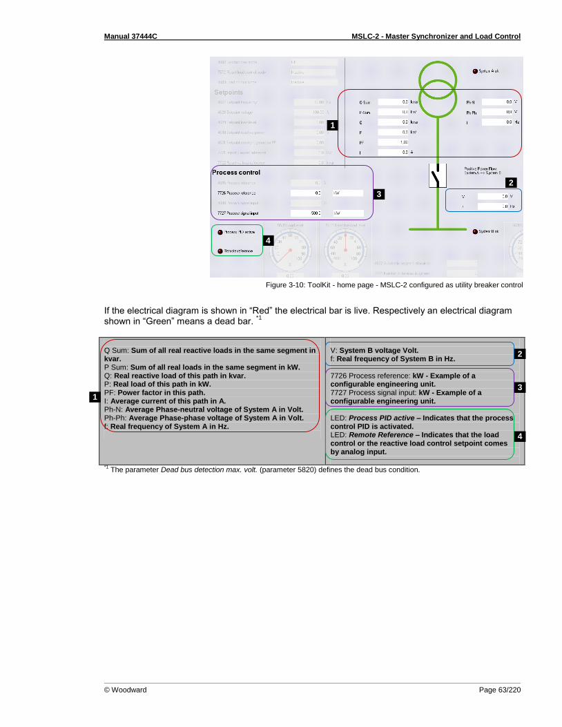
Manual 37444C MSLC-2 - Master Synchronizer and Load Control
© Woodward Page 63/220
Figure 3-10: ToolKit - home page - MSLC-2 configured as utility breaker control
If the electrical diagram is shown in “Red” the electrical bar is live. Respectively an electrical diagram shown in “Green” means a dead bar.
*1
Q Sum: Sum of all real reactive loads in the same segment in kvar. P Sum: Sum of all real loads in the same segment in kW. Q: Real reactive load of this path in kvar. P: Real load of this path in kW. PF: Power factor in this path. I: Average current of this path in A. Ph-N: Average Phase-neutral voltage of System A in Volt. Ph-Ph: Average Phase-phase voltage of System A in Volt. f: Real frequency of System A in Hz.
V: System B voltage Volt. f: Real frequency of System B in Hz. 7726 Process reference: kW - Example of a configurable engineering unit. 7727 Process signal input: kW - Example of a configurable engineering unit. LED: Process PID active – Indicates that the process control PID is activated. LED: Remote Reference – Indicates that the load control or the reactive load control setpoint comes by analog input.
*1 The parameter Dead bus detection max. volt. (parameter 5820) defines the dead bus condition.
4
1
2
3
2
3
4
1
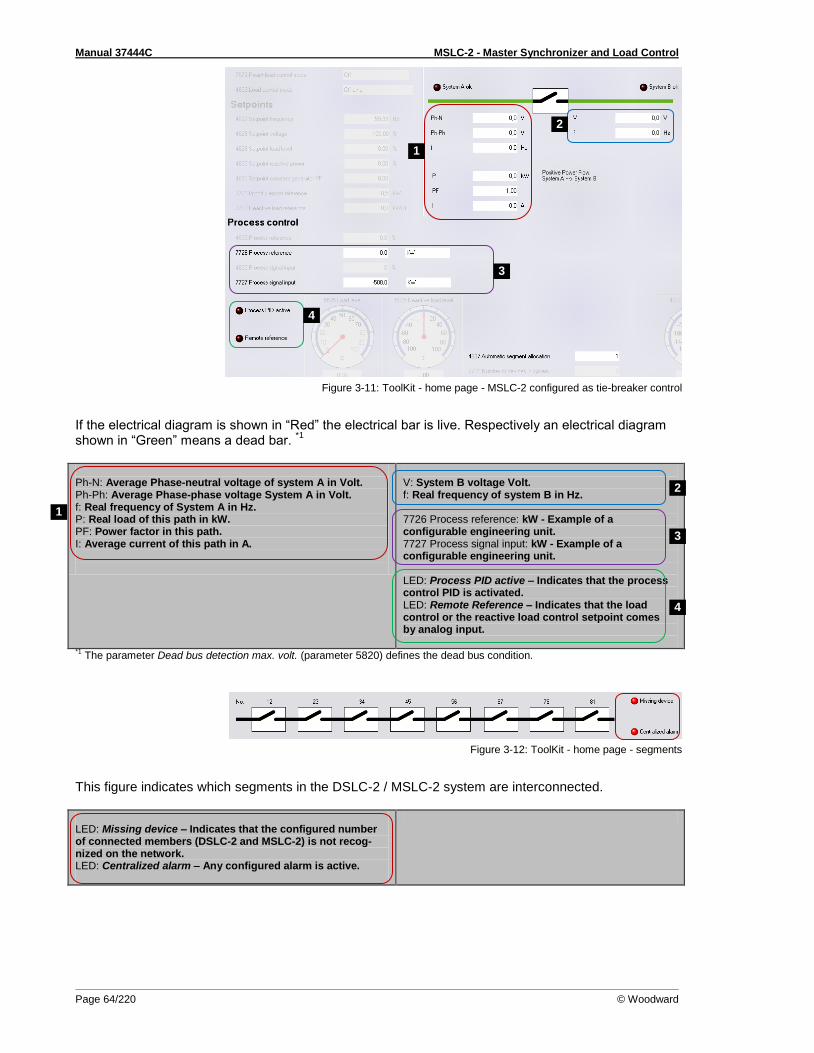
Manual 37444C MSLC-2 - Master Synchronizer and Load Control
Page 64/220 © Woodward
Figure 3-11: ToolKit - home page - MSLC-2 configured as tie-breaker control
If the electrical diagram is shown in “Red” the electrical bar is live. Respectively an electrical diagram shown in “Green” means a dead bar.
*1
Ph-N: Average Phase-neutral voltage of system A in Volt. Ph-Ph: Average Phase-phase voltage System A in Volt. f: Real frequency of System A in Hz. P: Real load of this path in kW. PF: Power factor in this path. I: Average current of this path in A.
V: System B voltage Volt. f: Real frequency of system B in Hz. 7726 Process reference: kW - Example of a configurable engineering unit. 7727 Process signal input: kW - Example of a configurable engineering unit. LED: Process PID active – Indicates that the process control PID is activated. LED: Remote Reference – Indicates that the load control or the reactive load control setpoint comes by analog input.
*1 The parameter Dead bus detection max. volt. (parameter 5820) defines the dead bus condition.
Figure 3-12: ToolKit - home page - segments
This figure indicates which segments in the DSLC-2 / MSLC-2 system are interconnected. LED: Missing device – Indicates that the configured number of connected members (DSLC-2 and MSLC-2) is not recog-nized on the network. LED: Centralized alarm – Any configured alarm is active.
4
2
3
2
3
4
1
1

Manual 37444C MSLC-2 - Master Synchronizer and Load Control
© Woodward Page 65/220
Menu 1 – Synchronizer This menu contains the adjustments of the synchronizer.
Figure 3-13: ToolKit – synchronizer
PID Frequency Control
ID Parameter CL Setting range Default Description
4539 Frequency synchronizer proportional gain
2 0.01 to 100.00 0.80 Frequency sync gain determines how fast the synchronizer re-sponds to an error in speed or phase. Adjust gain to provide sta-ble control during synchronizing. Lower value to slow response.
4540 Frequency synchronizer integral gain
2 0.00 to 20.00 0.50 Frequency sync integral gain compensates for delay in the syn-chronizer control loop. Prevents low frequency hunting and damp-ing (overshoot or undershoot). Lower value to slow response.
5505 Phase matching gain
2 1 to 99 5 The Phase matching gain increases or decreases the influence of the phase angle deviation to the frequency control. Prevents fre-quency hunting and damping (overshoot or undershoot) when the synchronizer is enabled with phase matching function.
5506 Phase matching df-start
2 0.02 to 0.25 Hz 0.05 Hz Phase matching is started if the frequency difference between the systems to be synchronized is below the configured value.
5707 Phase matching CB dwell time
2 0 to 60.0 s 0.5 s Dwell Time: This is the minimum time that the system A voltage, frequency and phase angle must be within the configured limits before the breaker will be closed. Set to lower time for quicker breaker closure commands.
5516 Start fre-quency con-trol level
1 0.00 to 70.00 Hz
55.00 Hz The frequency controller is activated when the monitored system B frequency has exceeded the value configured in this parameter. This prevents the MSLC-2 from attempting to control the frequen-cy while the engine is completing its start sequence.

Manual 37444C MSLC-2 - Master Synchronizer and Load Control
Page 66/220 © Woodward
ID Parameter CL Setting range Default Description
5517 Start fre-quency con-trol delay
1 0 to 999 s 1 s The frequency controller is enabled after the configured time for this parameter expires.
7783 Freq. Control setpoint source
Internal / Interface
Internal This setting determines from which source the Frequency control setpoint comes: Internal: The setpoint parameter 1750 System rated frequency is valid. Interface: The setpoint comes via RS-485 Modbus or TCP/IP Modbus Interface with parameter 7641.
Table 3-14: Parameter – synchronizer – PID frequency control
PID Voltage Control
ID Parameter CL Setting range Default Description
5610 Voltage synchronizer proportional gain
2 0.01 to 100.00 1.00 Voltage sync gain determines how fast the synchronizer responds to a voltage deviation. Adjust gain to provide stable control during synchronizing. Lower value to slow response.
5611 Voltage synchronizer integral gain
2 0.01 to 100.00 0.50 Voltage sync integral gain compensates for delay in the synchro-nizer voltage control loop. Prevents low voltage hunting and damping (overshoot or undershoot) when the synchronizer is en-abled. Lower value to slow response.
Table 3-15: Parameter – synchronizer – PID voltage control
Synchronizer Control
ID Parameter CL Setting range Default Description
5730 Synchroniza-tion CB
2 Slip frequency./. Phase matching
Slip frequency
Slip frequency: The frequency controller adjusts the frequency in a way, that the frequency of the variable system is marginal greater than the fixed system. When the synchronizing conditions are reached, a close command will be issued. The slipping fre-quency depends on the setting of Slip frequency setpoint offset (parameter 5502). Phase matching: The frequency controller adjusts the phase an-gle of the system B to that of the system A. NOTE: In the Permissive mode, phase matching is internally switched.
4712 Slip frequency setpoint offset
2 -0.50 to 0.50 Hz 0.10 Hz This value is the offset for the synchronization to the variable sys-tem to the fixed system. With this offset, the unit synchronizes with a positive or negative slip. Example: If this parameter is configured to 0.10 Hz and the busbar/mains frequency is 60.00 Hz, the synchronization setpoint is 60.10 Hz. If this parameter is configured to -0.10 Hz and the busbar/mains frequency is 60.00 Hz, the synchronization setpoint is 59.90 Hz.
5701 Positive frequency differential CB
2 0.02 to 0.49 Hz 0.18 Hz The prerequisite for a close command being issued for the CB is that the differential frequency is below the configured differential frequency. This value specifies the upper frequency (positive val-ue corresponds to positive slip > system B frequency is higher than system A frequency).
5702 Negative frequency differential CB
2 -0.49 to 0.00 Hz -0.10 Hz The prerequisite for a close command being issued for the CB is that the differential frequency is above the configured differential frequency. This value specifies the lower frequency limit (negative value corresponds to negative slip > system B frequency is less than system A frequency).
4717 Phase win-dow extend-ed maximum
2 0.0 to 60.0 ° 10.0 ° When closing the last breaker in a ring structure, the phase win-dow for the synchronizer is extended by this value
7513 Voltage matching
2 Disabled / Enabled
Enabled Enables or disables the synchronizer voltage matching function. Independent on this setting the voltage control is still executed but the synchronizer does not care about the voltage matching.
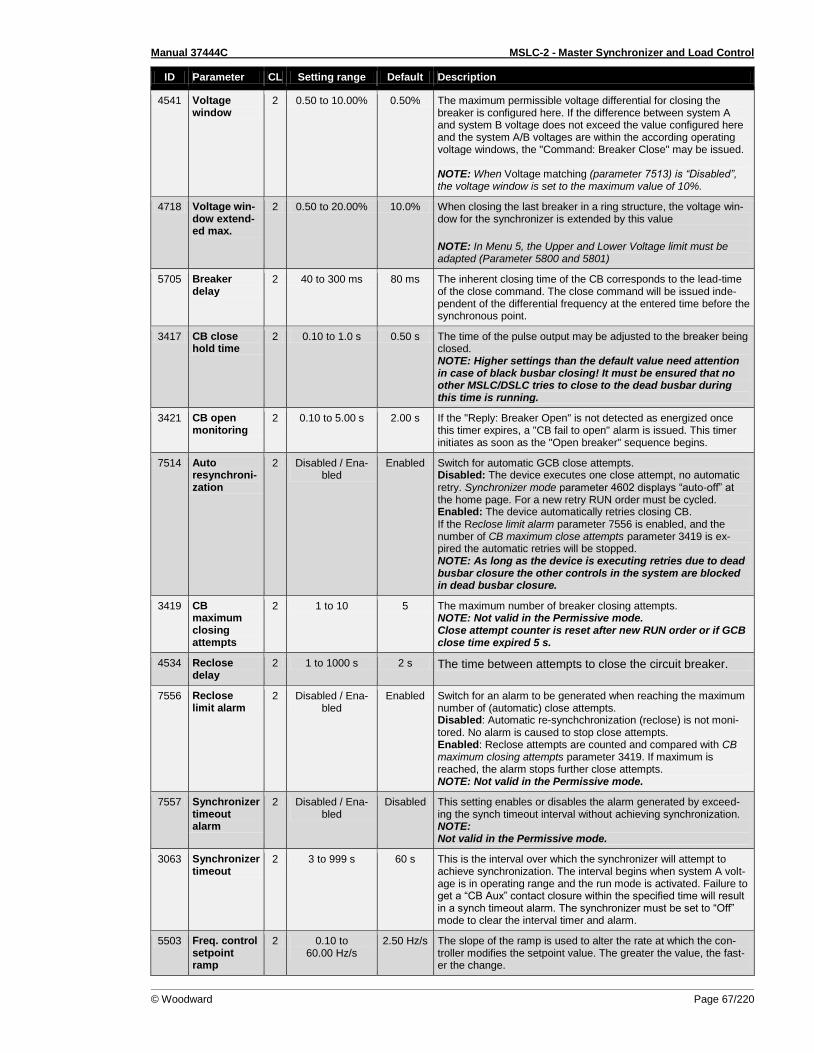
Manual 37444C MSLC-2 - Master Synchronizer and Load Control
© Woodward Page 67/220
ID Parameter CL Setting range Default Description
4541 Voltage window
2 0.50 to 10.00% 0.50% The maximum permissible voltage differential for closing the breaker is configured here. If the difference between system A and system B voltage does not exceed the value configured here and the system A/B voltages are within the according operating voltage windows, the "Command: Breaker Close" may be issued. NOTE: When Voltage matching (parameter 7513) is “Disabled”, the voltage window is set to the maximum value of 10%.
4718 Voltage win-dow extend-ed max.
2 0.50 to 20.00% 10.0% When closing the last breaker in a ring structure, the voltage win-dow for the synchronizer is extended by this value
NOTE: In Menu 5, the Upper and Lower Voltage limit must be adapted (Parameter 5800 and 5801)
5705 Breaker delay
2 40 to 300 ms 80 ms The inherent closing time of the CB corresponds to the lead-time of the close command. The close command will be issued inde-pendent of the differential frequency at the entered time before the synchronous point.
3417 CB close hold time
2 0.10 to 1.0 s 0.50 s The time of the pulse output may be adjusted to the breaker being closed. NOTE: Higher settings than the default value need attention in case of black busbar closing! It must be ensured that no other MSLC/DSLC tries to close to the dead busbar during this time is running.
3421 CB open monitoring
2 0.10 to 5.00 s 2.00 s If the "Reply: Breaker Open" is not detected as energized once this timer expires, a "CB fail to open" alarm is issued. This timer initiates as soon as the "Open breaker" sequence begins.
7514 Auto resynchroni-zation
2 Disabled / Ena-bled
Enabled Switch for automatic GCB close attempts. Disabled: The device executes one close attempt, no automatic retry. Synchronizer mode parameter 4602 displays “auto-off” at the home page. For a new retry RUN order must be cycled. Enabled: The device automatically retries closing CB. If the Reclose limit alarm parameter 7556 is enabled, and the number of CB maximum close attempts parameter 3419 is ex-pired the automatic retries will be stopped. NOTE: As long as the device is executing retries due to dead busbar closure the other controls in the system are blocked in dead busbar closure.
3419 CB maximum closing attempts
2 1 to 10 5 The maximum number of breaker closing attempts. NOTE: Not valid in the Permissive mode. Close attempt counter is reset after new RUN order or if GCB close time expired 5 s.
4534 Reclose delay
2 1 to 1000 s 2 s The time between attempts to close the circuit breaker.
7556 Reclose limit alarm
2 Disabled / Ena-bled
Enabled Switch for an alarm to be generated when reaching the maximum number of (automatic) close attempts. Disabled: Automatic re-synchchronization (reclose) is not moni-tored. No alarm is caused to stop close attempts. Enabled: Reclose attempts are counted and compared with CB maximum closing attempts parameter 3419. If maximum is reached, the alarm stops further close attempts. NOTE: Not valid in the Permissive mode.
7557 Synchronizer timeout alarm
2 Disabled / Ena-bled
Disabled This setting enables or disables the alarm generated by exceed-ing the synch timeout interval without achieving synchronization. NOTE: Not valid in the Permissive mode.
3063 Synchronizer timeout
2 3 to 999 s 60 s This is the interval over which the synchronizer will attempt to achieve synchronization. The interval begins when system A volt-age is in operating range and the run mode is activated. Failure to get a “CB Aux” contact closure within the specified time will result in a synch timeout alarm. The synchronizer must be set to “Off” mode to clear the interval timer and alarm.
5503 Freq. control setpoint ramp
2 0.10 to 60.00 Hz/s
2.50 Hz/s The slope of the ramp is used to alter the rate at which the con-troller modifies the setpoint value. The greater the value, the fast-er the change.
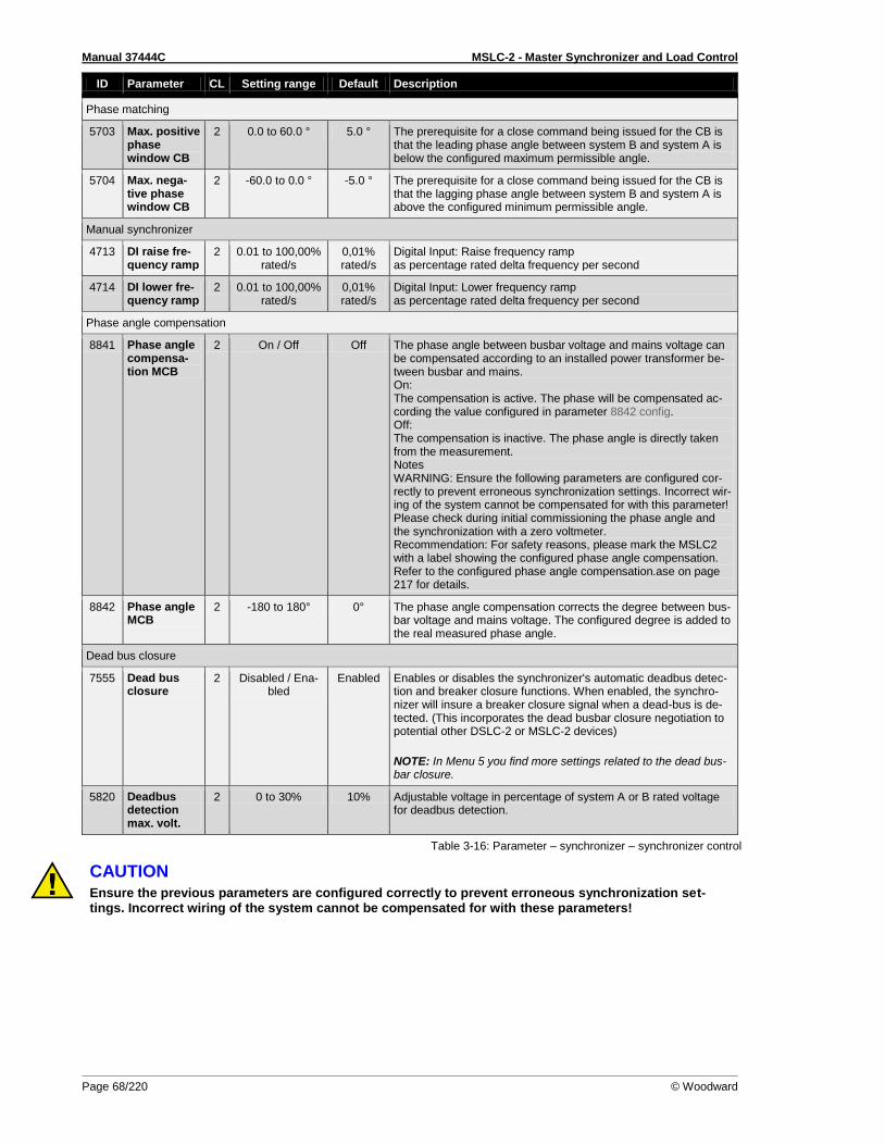
Manual 37444C MSLC-2 - Master Synchronizer and Load Control
Page 68/220 © Woodward
ID Parameter CL Setting range Default Description
Phase matching
5703 Max. positive phase window CB
2 0.0 to 60.0 ° 5.0 ° The prerequisite for a close command being issued for the CB is that the leading phase angle between system B and system A is below the configured maximum permissible angle.
5704 Max. nega-tive phase window CB
2 -60.0 to 0.0 ° -5.0 ° The prerequisite for a close command being issued for the CB is that the lagging phase angle between system B and system A is above the configured minimum permissible angle.
Manual synchronizer
4713 DI raise fre-quency ramp
2 0.01 to 100,00% rated/s
0,01% rated/s
Digital Input: Raise frequency ramp as percentage rated delta frequency per second
4714 DI lower fre-quency ramp
2 0.01 to 100,00% rated/s
0,01% rated/s
Digital Input: Lower frequency ramp as percentage rated delta frequency per second
Phase angle compensation
8841 Phase angle compensa-tion MCB
2 On / Off Off The phase angle between busbar voltage and mains voltage can be compensated according to an installed power transformer be-tween busbar and mains. On: The compensation is active. The phase will be compensated ac-cording the value configured in parameter 8842 config. Off: The compensation is inactive. The phase angle is directly taken from the measurement. Notes WARNING: Ensure the following parameters are configured cor-rectly to prevent erroneous synchronization settings. Incorrect wir-ing of the system cannot be compensated for with this parameter! Please check during initial commissioning the phase angle and the synchronization with a zero voltmeter. Recommendation: For safety reasons, please mark the MSLC2 with a label showing the configured phase angle compensation. Refer to the configured phase angle compensation.ase on page 217 for details.
8842 Phase angle MCB
2 -180 to 180° 0° The phase angle compensation corrects the degree between bus-bar voltage and mains voltage. The configured degree is added to the real measured phase angle.
Dead bus closure
7555 Dead bus closure
2 Disabled / Ena-bled
Enabled Enables or disables the synchronizer's automatic deadbus detec-tion and breaker closure functions. When enabled, the synchro-nizer will insure a breaker closure signal when a dead-bus is de-tected. (This incorporates the dead busbar closure negotiation to potential other DSLC-2 or MSLC-2 devices)
NOTE: In Menu 5 you find more settings related to the dead bus-bar closure.
5820 Deadbus detection max. volt.
2 0 to 30% 10% Adjustable voltage in percentage of system A or B rated voltage for deadbus detection.
Table 3-16: Parameter – synchronizer – synchronizer control
CAUTION Ensure the previous parameters are configured correctly to prevent erroneous synchronization set-tings. Incorrect wiring of the system cannot be compensated for with these parameters!
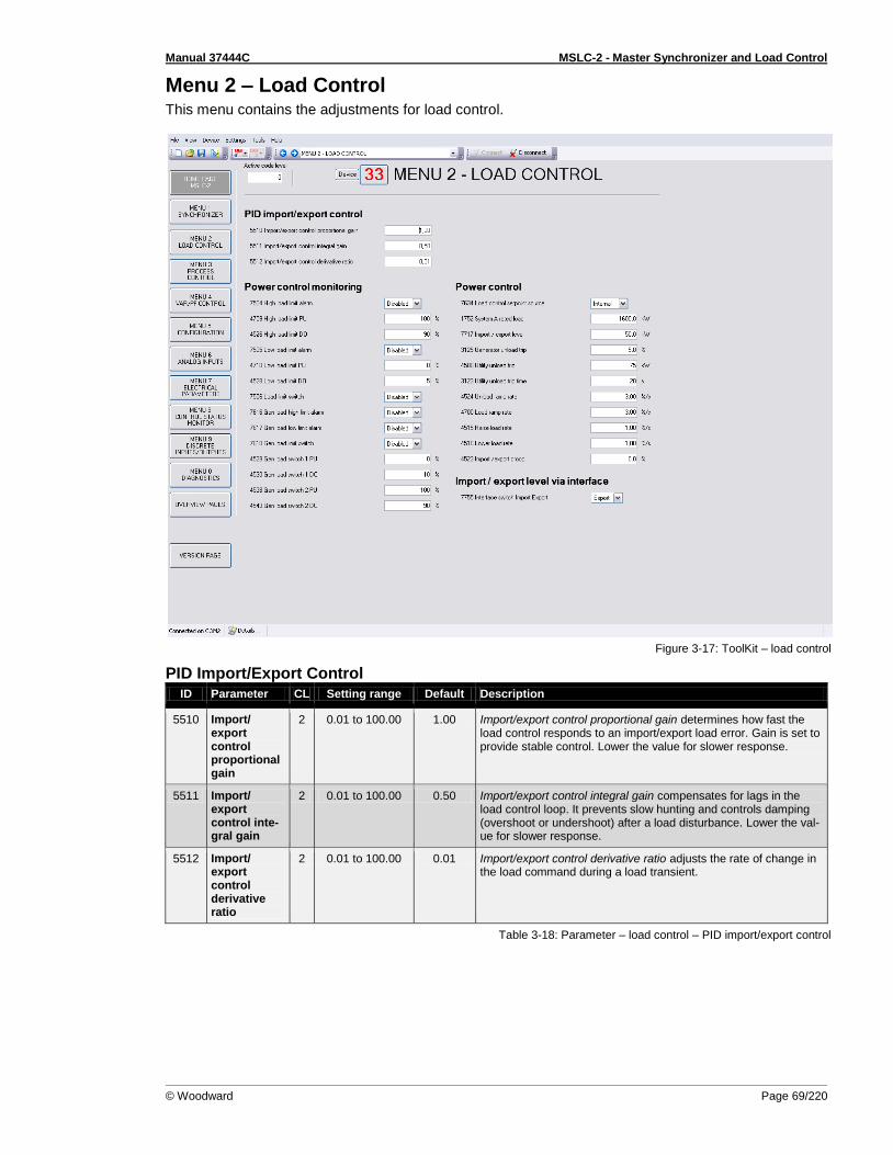
Manual 37444C MSLC-2 - Master Synchronizer and Load Control
© Woodward Page 69/220
Menu 2 – Load Control This menu contains the adjustments for load control.
Figure 3-17: ToolKit – load control
PID Import/Export Control
ID Parameter CL Setting range Default Description
5510 Import/ export control proportional gain
2 0.01 to 100.00 1.00 Import/export control proportional gain determines how fast the load control responds to an import/export load error. Gain is set to provide stable control. Lower the value for slower response.
5511 Import/ export control inte-gral gain
2 0.01 to 100.00 0.50 Import/export control integral gain compensates for lags in the load control loop. It prevents slow hunting and controls damping (overshoot or undershoot) after a load disturbance. Lower the val-ue for slower response.
5512 Import/ export control derivative ratio
2 0.01 to 100.00 0.01 Import/export control derivative ratio adjusts the rate of change in the load command during a load transient.
Table 3-18: Parameter – load control – PID import/export control

Manual 37444C MSLC-2 - Master Synchronizer and Load Control
Page 70/220 © Woodward
Power Control Monitoring
ID Parameter CL Setting range Default Description
7504 High load limit alarm
2 Disabled / Ena-bled
Disabled The High load limit alarm specifies if the high load limit alarm will activate (energize) the “High Limit” relay (Terminal 44).
4709 High load limit PU
2 -150 to 150% 100% The High load limit PU is the import/export load level where (if en-abled) the “High Limit” relay is energized and the high limit alarm is activated. The percentage value relates to system A rated load (parameter 1752).
4526 High load limit DO
2 -150 to 150% 90% The High load limit DO is the import/export load level where (if enabled) the “High Limit” relay is de-energized and the high limit alarm is deactivated. The percentage value relates to system A rated load (parameter 1752).
7505 Low load limit alarm
2 Disabled / Ena-bled
Disabled The Low load limit alarm specifies if the low load limit alarm will activate (energize) the “Low Limit” relay (Terminal 45).
4710 Low load limit PU
2 0 to 100% 0% The Low load limit PU is the import/export load level where (if en-abled) the “Low Limit” relay is energized and the low limit alarm is activated. The percentage value relates to system A rated load (parameter 1752).
4528 Low load limit DO
2 -2 to 150% 5% The Low load limit DO is the import/export load level where (if en-abled) the “Low Limit” relay is de-energized and the low limit alarm is deactivated. The percentage value relates to system A rated load (parameter 1752).
7506 Load limit switch
2 Disabled / Ena-bled
Disabled Load limit switch specifies if the “High Limit” and “Low Limit” re-lays will activate on high or low limit alarm.
7616 Gen load high limit alarm
2 Disabled / Ena-bled
Disabled Generator load high limit alarm specifies if the generator high load limit alarm will activate the “High Limit” relay (Terminal 44). The generator high limit alarm is activated when the MSLC-2 is required to output a system load of 100% to the DSLC-2 controls
in order to meet its reference. NOTE: The “Alarm” relay includes additional the self-test function. Alarm active means relay open.
7617 Gen load low limit alarm
2 Disabled / Ena-bled
Disabled Generator load low limit alarm specifies if the generator low load limit alarm will activate the “Low Limit” relay (Terminal 45). The generator low limit alarm is caused when the MSLC-2 is re-quired to output a system load of 0% to the DSLC-2 controls in order to meet its reference.
7618 Gen load limit switch
2 Disabled / Ena-bled
Disabled Generator load limit switch specifies if the high and low limit alarms will activate the “Load Switch 1” or “Load Switch 2” relay when the system load setpoint reaches 100% or respectively 0%.
4529 Gen Load switch 1 PU
2 0 to 100% 0% Generator Load switch 1 PU is the system load level where the “Load Switch1” relay is energized.
4530 Gen Load switch 1 DO
2 0 to 100% 10% Generator Load switch 1 DO is the system load level where the “Load Switch1” relay is de-energized.
4538 Gen Load switch 2 PU
2 0 to 100% 100% Generator Load switch 2 PU is the system load level where the “Load Switch2” relay is energized.
4543 Gen Load switch 2 DO
2 0 to 100% 90% Generator Load switch 2 DO is the system load level where the “Load Switch2” relay is de-energized.
Table 3-19: Parameter – load control – power control monitoring
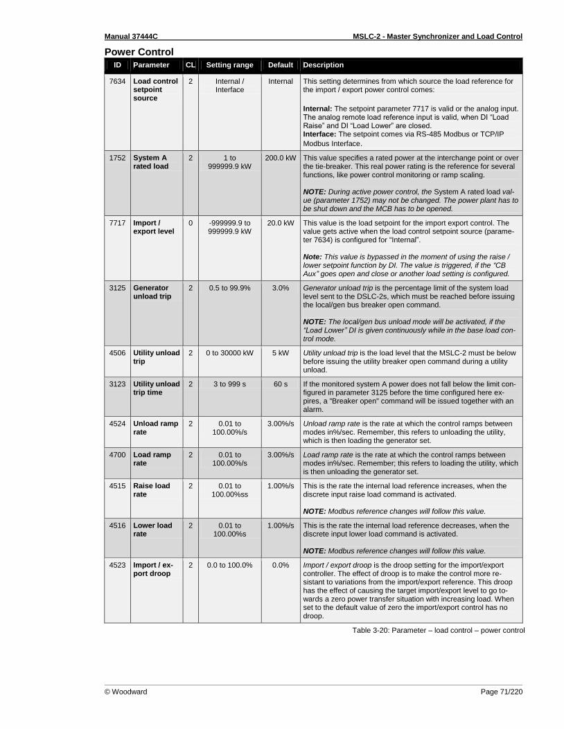
Manual 37444C MSLC-2 - Master Synchronizer and Load Control
© Woodward Page 71/220
Power Control
ID Parameter CL Setting range Default Description
7634 Load control setpoint source
2 Internal / Interface
Internal This setting determines from which source the load reference for the import / export power control comes:
Internal: The setpoint parameter 7717 is valid or the analog input. The analog remote load reference input is valid, when DI “Load Raise” and DI “Load Lower” are closed. Interface: The setpoint comes via RS-485 Modbus or TCP/IP
Modbus Interface.
1752 System A rated load
2 1 to 999999.9 kW
200.0 kW This value specifies a rated power at the interchange point or over the tie-breaker. This real power rating is the reference for several functions, like power control monitoring or ramp scaling. NOTE: During active power control, the System A rated load val-ue (parameter 1752) may not be changed. The power plant has to be shut down and the MCB has to be opened.
7717 Import / export level
0 -999999.9 to 999999.9 kW
20.0 kW This value is the load setpoint for the import export control. The value gets active when the load control setpoint source (parame-ter 7634) is configured for “Internal”. Note: This value is bypassed in the moment of using the raise / lower setpoint function by DI. The value is triggered, if the “CB Aux” goes open and close or another load setting is configured.
3125 Generator unload trip
2 0.5 to 99.9% 3.0% Generator unload trip is the percentage limit of the system load level sent to the DSLC-2s, which must be reached before issuing the local/gen bus breaker open command. NOTE: The local/gen bus unload mode will be activated, if the “Load Lower” DI is given continuously while in the base load con-trol mode.
4506 Utility unload trip
2 0 to 30000 kW 5 kW Utility unload trip is the load level that the MSLC-2 must be below before issuing the utility breaker open command during a utility unload.
3123 Utility unload trip time
2 3 to 999 s 60 s If the monitored system A power does not fall below the limit con-figured in parameter 3125 before the time configured here ex-pires, a "Breaker open" command will be issued together with an alarm.
4524 Unload ramp rate
2 0.01 to 100.00%/s
3.00%/s Unload ramp rate is the rate at which the control ramps between modes in%/sec. Remember, this refers to unloading the utility, which is then loading the generator set.
4700 Load ramp rate
2 0.01 to 100.00%/s
3.00%/s Load ramp rate is the rate at which the control ramps between modes in%/sec. Remember; this refers to loading the utility, which is then unloading the generator set.
4515 Raise load rate
2 0.01 to 100.00%ss
1.00%/s This is the rate the internal load reference increases, when the discrete input raise load command is activated. NOTE: Modbus reference changes will follow this value.
4516 Lower load rate
2 0.01 to 100.00%s
1.00%/s This is the rate the internal load reference decreases, when the discrete input lower load command is activated. NOTE: Modbus reference changes will follow this value.
4523 Import / ex-port droop
2 0.0 to 100.0% 0.0% Import / export droop is the droop setting for the import/export controller. The effect of droop is to make the control more re-sistant to variations from the import/export reference. This droop has the effect of causing the target import/export level to go to-wards a zero power transfer situation with increasing load. When set to the default value of zero the import/export control has no droop.
Table 3-20: Parameter – load control – power control
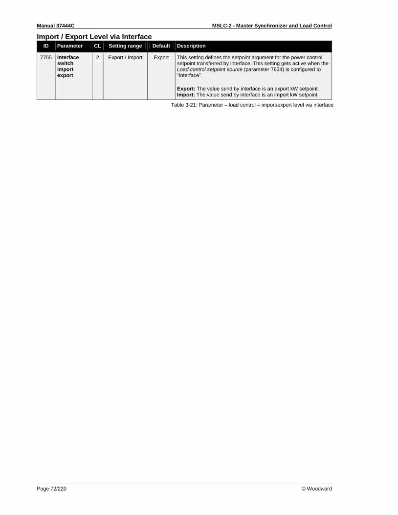
Manual 37444C MSLC-2 - Master Synchronizer and Load Control
Page 72/220 © Woodward
Import / Export Level via Interface
ID Parameter CL Setting range Default Description
7755 Interface switch import export
2 Export / Import Export This setting defines the setpoint argument for the power control setpoint transferred by interface. This setting gets active when the Load control setpoint source (parameter 7634) is configured to “Interface”.
Export: The value send by interface is an export kW setpoint. Import: The value send by interface is an import kW setpoint.
Table 3-21: Parameter – load control – import/export level via interface
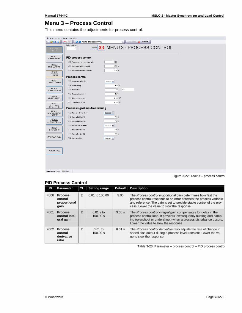
Manual 37444C MSLC-2 - Master Synchronizer and Load Control
© Woodward Page 73/220
Menu 3 – Process Control This menu contains the adjustments for process control.
Figure 3-22: ToolKit – process control
PID Process Control
ID Parameter CL Setting range Default Description
4500 Process control proportional gain
2 0.01 to 100.00 3.00 The Process control proportional gain determines how fast the process control responds to an error between the process variable and reference. The gain is set to provide stable control of the pro-cess. Lower the value to slow the response.
4501 Process control inte-gral gain
2 0.01 s to 100.00 s
3.00 s The Process control integral gain compensates for delay in the process control loop. It prevents low frequency hunting and damp-ing (overshoot or undershoot) when a process disturbance occurs. Lower the value to slow the response.
4502 Process control derivative ratio
2 0.01 to 100.00 s
0.01 s The Process control derivative ratio adjusts the rate of change in speed bias output during a process level transient. Lower the val-ue to slow the response.
Table 3-23: Parameter – process control – PID process control
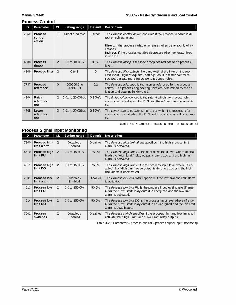
Manual 37444C MSLC-2 - Master Synchronizer and Load Control
Page 74/220 © Woodward
Process Control
ID Parameter CL Setting range Default Description
7559 Process control action
´2 Direct / Indirect Direct The Process control action specifies if the process variable is di-rect or indirect acting.
Direct: If the process variable increases when generator load in-creases. Indirect: If the process variable decreases when generator load increases.
4508 Process droop
2 0.0 to 100.0% 0.0% The Process droop is the load droop desired based on process level.
4509 Process filter 2 0 to 8 0 The Process filter adjusts the bandwidth of the filter on the pro-cess input. Higher frequency settings result in faster control re-sponse, but also more response to process noise.
7737 Process reference
0 -999999.9 to 999999.9
0.2 The Process reference is the internal reference for the process control. The process engineering units are determined by the se-lection and settings in Menu 6.1.
4504 Raise reference rate
2 0.01 to 20.00%/s 0.10%/s The Raise reference rate is the rate at which the process refer-ence is increased when the DI “Load Raise” command is activat-ed.
4505 Lower reference rate
2 0.01 to 20.00%/s 0.10%/s The Lower reference rate is the rate at which the process refer-ence is decreased when the DI “Load Lower” command is activat-ed.
Table 3-24: Parameter – process control – process control
Process Signal Input Monitoring
ID Parameter CL Setting range Default Description
7500 Process high limit alarm
2 Disabled / Enabled
Disabled The Process high limit alarm specifies if the high process limit alarm is activated.
4510 Process high limit PU
2 0.0 to 150.0% 75.0% The Process high limit PU is the process input level where (if ena-bled) the “High Limit” relay output is energized and the high limit alarm is activated.
4511 Process high limit DO
2 0.0 to 150.0% 75.0% The Process high limit DO is the process input level where (if en-abled) the “High Limit” relay output is de-energized and the high limit alarm is deactivated.
7501 Process low limit alarm
2 Disabled / Enabled
Disabled The Process low limit alarm specifies if the low process limit alarm is activated.
4513 Process low limit PU
2 0.0 to 150.0% 50.0% The Process low limit PU is the process input level where (if ena-bled) the “Low Limit” relay output is energized and the low limit alarm is activated.
4514 Process low limit DO
2 0.0 to 150.0% 50.0% The Process low limit DO is the process input level where (if ena-bled) the “Low Limit” relay output is de-energized and the low limit alarm is deactivated.
7502 Process switches
2 Disabled / Enabled
Disabled The Process switch specifies if the process high and low limits will activate the “High Limit” and “Low Limit” relay outputs.
Table 3-25: Parameter – process control – process signal input monitoring

Manual 37444C MSLC-2 - Master Synchronizer and Load Control
© Woodward Page 75/220
Menu 4 – Voltage/Var/PF Control This menu contains the adjustments for reactive load control.
Figure 3-26: ToolKit – voltage/var/pf control
Voltage Control
ID Parameter CL Setting range Default Description
7784 Voltage con-trol setpoint source
Internal / Interface
Internal This setting determines from which source the Voltage control setpoint comes: Internal: The setpoint parameter 5600 Voltage control setpoint is valid. Interface: The setpoint comes via RS-485 Modbus or TCP/IP Modbus Interface with parameter 7780.
5600 Voltage control setpoint
1 50 to 650.000 V 480 V This value is the reference for the voltage controller when per-forming isolated and/or no-load operations. Usually the voltage control setpoint is the same like the rated voltage setting. In some cases it could be desired to have another setpoint in isolation op-eration.
5603 Voltage control setpoint ramp
2 1.00 to 300.00%/s
5.00%/s The different setpoint values are supplied to the controller via this ramp. The slope of the ramp is used to alter the rate at which the controller modifies the setpoint value. A greater value will create a faster change in the setpoint.
Manual synchronizer
4715 DI raise voltage ramp
2 000.01 to 100.00%rated/s
000.05%rated/s
Digital Input: Raise voltage ramp as percentage rated delta voltage per second
4716 DI lower voltage ramp
2 000.01 to 100.00%rated/s
000.05%rated/s
Digital Input: Lower voltage ramp as percentage rated delta voltage per second
Table 3-27: Parameter – voltage/var/pf control – voltage control
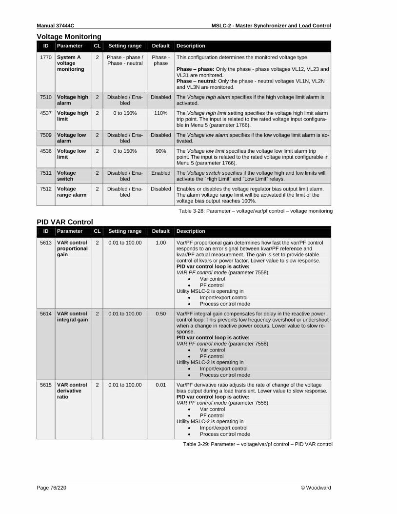
Manual 37444C MSLC-2 - Master Synchronizer and Load Control
Page 76/220 © Woodward
Voltage Monitoring
ID Parameter CL Setting range Default Description
1770 System A voltage monitoring
2 Phase - phase / Phase - neutral
Phase - phase
This configuration determines the monitored voltage type. Phase – phase: Only the phase - phase voltages VL12, VL23 and VL31 are monitored. Phase – neutral: Only the phase - neutral voltages VL1N, VL2N and VL3N are monitored.
7510 Voltage high alarm
2 Disabled / Ena-bled
Disabled The Voltage high alarm specifies if the high voltage limit alarm is activated.
4537 Voltage high limit
2 0 to 150% 110% The Voltage high limit setting specifies the voltage high limit alarm trip point. The input is related to the rated voltage input configura-ble in Menu 5 (parameter 1766).
7509 Voltage low alarm
2 Disabled / Ena-bled
Disabled The Voltage low alarm specifies if the low voltage limit alarm is ac-tivated.
4536 Voltage low limit
2 0 to 150% 90% The Voltage low limit specifies the voltage low limit alarm trip point. The input is related to the rated voltage input configurable in Menu 5 (parameter 1766).
7511 Voltage switch
2 Disabled / Ena-bled
Enabled The Voltage switch specifies if the voltage high and low limits will activate the “High Limit” and “Low Limit” relays.
7512 Voltage range alarm
2 Disabled / Ena-bled
Disabled Enables or disables the voltage regulator bias output limit alarm. The alarm voltage range limit will be activated if the limit of the voltage bias output reaches 100%.
Table 3-28: Parameter – voltage/var/pf control – voltage monitoring
PID VAR Control
ID Parameter CL Setting range Default Description
5613 VAR control proportional gain
2 0.01 to 100.00 1.00 Var/PF proportional gain determines how fast the var/PF control responds to an error signal between kvar/PF reference and kvar/PF actual measurement. The gain is set to provide stable control of kvars or power factor. Lower value to slow response. PID var control loop is active: VAR PF control mode (parameter 7558)
Var control
PF control Utility MSLC-2 is operating in
Import/export control
Process control mode
5614 VAR control integral gain
2 0.01 to 100.00 0.50 Var/PF integral gain compensates for delay in the reactive power control loop. This prevents low frequency overshoot or undershoot when a change in reactive power occurs. Lower value to slow re-sponse. PID var control loop is active: VAR PF control mode (parameter 7558)
Var control
PF control Utility MSLC-2 is operating in
Import/export control
Process control mode
5615 VAR control derivative ratio
2 0.01 to 100.00 0.01 Var/PF derivative ratio adjusts the rate of change of the voltage bias output during a load transient. Lower value to slow response. PID var control loop is active: VAR PF control mode (parameter 7558)
Var control
PF control Utility MSLC-2 is operating in
Import/export control
Process control mode
Table 3-29: Parameter – voltage/var/pf control – PID VAR control

Manual 37444C MSLC-2 - Master Synchronizer and Load Control
© Woodward Page 77/220
Var Control
ID Parameter CL Setting range Default Description
7558 VAR PF con-trol mode
2 PF Control / VAR Control /
Constant Gener-ator PF
VAR Control
This setting specifies the reactive load controller:
PF Control: If the DI process control or DI import/export control is active, the control will maintain a constant PF across the utility tie (ID 5620). Otherwise the DSLC’s are forced for a constant gen-erator PF (ID 5621). VAR Control: If the DI process control or DI import/export control is active, the control will maintain a constant var load level across the utility tie (ID 7723). Otherwise the DSLC’s are forced for a constant generator PF (ID 5621). Constant Generator PF: The control will always send a constant generator PF (ID 5621) to the DSLC-2.
1758 System A rated react. power
2 0.1 to 999999.9 kvar
190.0 kvar
This value specifies the system A reactive power rating, which is used as a reference figure for related functions. If unknown, set to 60% of the kVA or 80% of the kW rating, which is the kvar load at 0.8 lagging power factor.
7723 KVAR reference
2 -999999.9 to 999999.9 kvar
10.0 kvar This is the setpoint for the reactive load control when the VAR PF control mode is configured for “VAR control”.
4690 Rated appar. power
- Info kVA This field indicates the internal calculated appearance power which is calculated out of the kW and kvar rating.
5622 Reactive power setpoint ramp
2 0.01 to 100.00%/s
10.00%/s When issuing of different setpoints or during ramp up and ramp down of the reactive load. The ramp setting is related to rated re-active power (parameter 1758).
5620 Power factor reference
1 - 0.5 to 0.5* Displayed text in case of wrong input: “min -0.999, max 1.000”
1.000 This is the setpoint for the reactive load control when the VAR PF control mode (parameter 7558) is configured for “PF control”. The designations “-” and “+” stand for:
Inductive/lagging (+) - generator supplying vars
Capacitive/leading (-) - generator absorbing vars *NOTE: ToolKit works fine but input error messaging has no ade-quate standard text available.
5621 Constant gen. PF reference
1 -0.999 to 1.000 0.950 This is the constant reference the MSLC-2 sends to the DSLC-2 controls (the reference level at which to maintain each DSLC-2 controls generator) when in constant generator power factor con-trol mode. In this mode the DSLC-2 control will maintain a con-stant generator PF level regardless of the amount of vars being absorbed / generated across the utility tie. This setpoint is active when the VAR PF control mode (parameter 7558) is configured on “Constant Generator PF”. NOTE: The designations “+” stands for generate inductive/lagging reactive power with the generator. The designations “-” stands for absorb capacitive/leading reactive power with the generator. NOTE: It is recommended that the constant generator power fac-tor control mode be used in applications where the total generator kvar capacity is less than the kvar load of the system.
Interface: only for Power factor control mode
7635 VAR control setpoint source
2 Internal / Interface
Internal This parameter determines the reactive load control setpoint source: Internal The setpoint comes from:
o KVAR reference (parameter 7723) at the in-terchange point when VAR PF control mode (parameter 7558) is configured on “VAR con-trol”.
o Power factor reference (parameter 5620) at the interchange point when VAR PF control mode (parameter 7558) is configured on “PF control”.
o Power factor reference at the interchange point over analog input (parameter 7718) when VAR PF control mode (parameter 7558) is configured on “PF control” and the remote

Manual 37444C MSLC-2 - Master Synchronizer and Load Control
Page 78/220 © Woodward
ID Parameter CL Setting range Default Description
function is activated. (DI “Voltage Raise” / “Voltage Lower” set).
Interface The setpoint comes from the interface (via RS-485 Modbus or TCP/IP Modbus, Address 7640). The setpoint is a power factor setpoint. Therefore the VAR PF control mode (parameter 7558) has to be configured to one of the PF settings.
“PF Control”: The Modbus parameter 7640 will be the power factor reference value at the interchange point.
“Constant Generator PF”: The Modbus parameter 7640 will be the power factor reference for a constant power factor reference sent to the DSLC-2s.
Table 3-30: Parameter – voltage/var/pf control – VAR control

Manual 37444C MSLC-2 - Master Synchronizer and Load Control
© Woodward Page 79/220
Menu 5 – Configuration This menu contains system rated frequency, generator rated voltage, PT and CT settings, with operat-ing range and device number for the configuration of the MSLC-2.
Figure 3-31: ToolKit – configuration
General
NOTE Beside the System A 3-phase or 1-phase measurement the MSLC-2 provides a busbar 1-phase measurements and an auxiliary busbar 3-phase measurement. The busbar 1-phase measurement at the terminals 37-40 is obligatory and has to be connected in each applica-tion. The auxiliary busbar 3-phase AC measurement at the terminals 21-28 can additionally be used. When both measurements are used the busbar voltage has to be connected to both inputs. With the parallel use of the auxiliary busbar measurement, the MSLC-2 can determine correct voltages on all 3 phases and becomes a part of the operating range- and the phase rotation monitoring.
NOTE Connection plausibility is checked: If the Busbar is not connected but Auxiliary Busbar is connected the "Busbar mismatch” Alarm ID 7770 occurs. This alarm is triggered when either the L1-L2 phase-phase voltage of the Aux busbar or the original busbar is lower or higher than the operation ranges (but higher than dead bus closure limit). Dependent on the configuration "auxiliary busbar measurement" it will be checked when
Auxiliary system available = "No" then the auxiliary busbar has no influence and therefore an alarm is never triggered
Auxiliary system available = "Yes" then the auxiliary busbar with L1-L2 and the original busbar L1-L2 is checked if lower or higher than operating ranges
The dead busbar closure shall be blocked, when this alarm occurs.
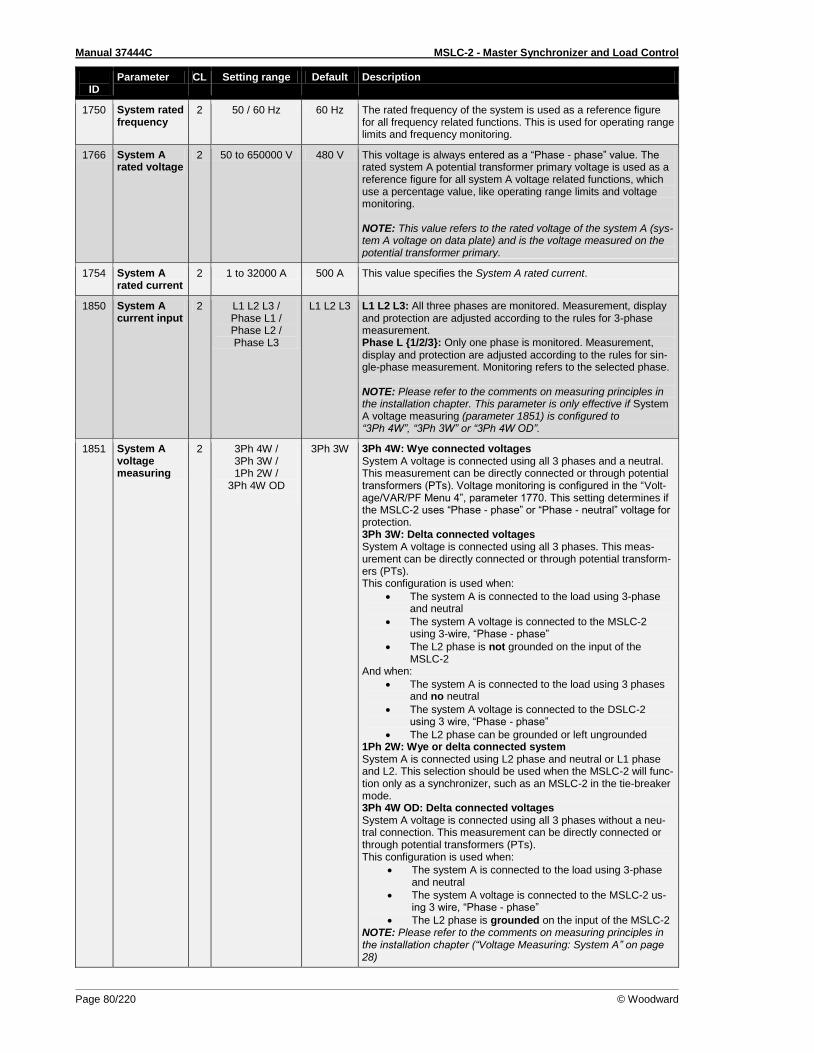
Manual 37444C MSLC-2 - Master Synchronizer and Load Control
Page 80/220 © Woodward
ID
Parameter CL Setting range Default Description
1750 System rated frequency
2 50 / 60 Hz 60 Hz The rated frequency of the system is used as a reference figure for all frequency related functions. This is used for operating range limits and frequency monitoring.
1766 System A rated voltage
2 50 to 650000 V 480 V This voltage is always entered as a “Phase - phase” value. The rated system A potential transformer primary voltage is used as a reference figure for all system A voltage related functions, which use a percentage value, like operating range limits and voltage monitoring. NOTE: This value refers to the rated voltage of the system A (sys-tem A voltage on data plate) and is the voltage measured on the potential transformer primary.
1754 System A rated current
2 1 to 32000 A 500 A This value specifies the System A rated current.
1850 System A current input
2 L1 L2 L3 / Phase L1 / Phase L2 / Phase L3
L1 L2 L3 L1 L2 L3: All three phases are monitored. Measurement, display and protection are adjusted according to the rules for 3-phase measurement. Phase L 1/2/3: Only one phase is monitored. Measurement, display and protection are adjusted according to the rules for sin-gle-phase measurement. Monitoring refers to the selected phase. NOTE: Please refer to the comments on measuring principles in the installation chapter. This parameter is only effective if System A voltage measuring (parameter 1851) is configured to “3Ph 4W”, “3Ph 3W” or “3Ph 4W OD”.
1851 System A voltage measuring
2 3Ph 4W / 3Ph 3W / 1Ph 2W /
3Ph 4W OD
3Ph 3W 3Ph 4W: Wye connected voltages System A voltage is connected using all 3 phases and a neutral. This measurement can be directly connected or through potential transformers (PTs). Voltage monitoring is configured in the “Volt-age/VAR/PF Menu 4”, parameter 1770. This setting determines if the MSLC-2 uses “Phase - phase” or “Phase - neutral” voltage for protection. 3Ph 3W: Delta connected voltages System A voltage is connected using all 3 phases. This meas-urement can be directly connected or through potential transform-ers (PTs). This configuration is used when:
The system A is connected to the load using 3-phase and neutral
The system A voltage is connected to the MSLC-2 using 3-wire, “Phase - phase”
The L2 phase is not grounded on the input of the MSLC-2
And when:
The system A is connected to the load using 3 phases and no neutral
The system A voltage is connected to the DSLC-2 using 3 wire, “Phase - phase”
The L2 phase can be grounded or left ungrounded 1Ph 2W: Wye or delta connected system System A is connected using L2 phase and neutral or L1 phase and L2. This selection should be used when the MSLC-2 will func-tion only as a synchronizer, such as an MSLC-2 in the tie-breaker mode. 3Ph 4W OD: Delta connected voltages System A voltage is connected using all 3 phases without a neu-tral connection. This measurement can be directly connected or through potential transformers (PTs). This configuration is used when:
The system A is connected to the load using 3-phase and neutral
The system A voltage is connected to the MSLC-2 us-ing 3 wire, “Phase - phase”
The L2 phase is grounded on the input of the MSLC-2 NOTE: Please refer to the comments on measuring principles in the installation chapter (“Voltage Measuring: System A” on page 28)
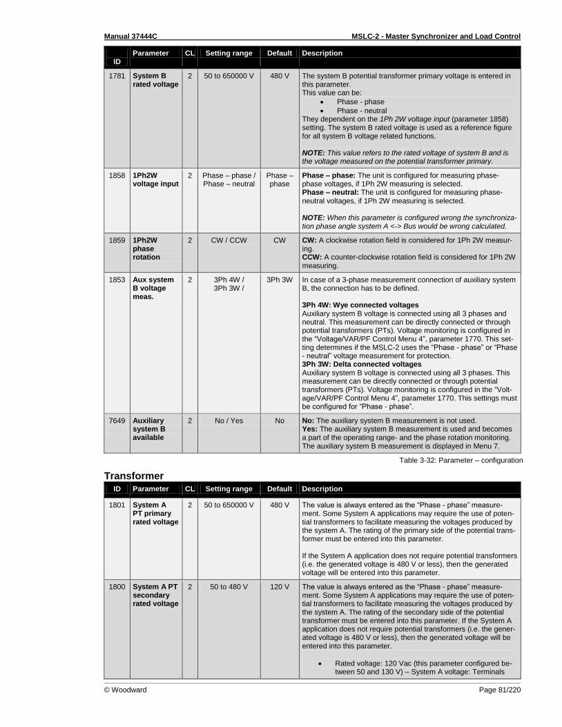
Manual 37444C MSLC-2 - Master Synchronizer and Load Control
© Woodward Page 81/220
ID
Parameter CL Setting range Default Description
1781 System B rated voltage
2 50 to 650000 V 480 V The system B potential transformer primary voltage is entered in this parameter. This value can be:
Phase - phase
Phase - neutral They dependent on the 1Ph 2W voltage input (parameter 1858) setting. The system B rated voltage is used as a reference figure for all system B voltage related functions. NOTE: This value refers to the rated voltage of system B and is the voltage measured on the potential transformer primary.
1858 1Ph2W voltage input
2 Phase – phase / Phase – neutral
Phase – phase
Phase – phase: The unit is configured for measuring phase-phase voltages, if 1Ph 2W measuring is selected. Phase – neutral: The unit is configured for measuring phase-neutral voltages, if 1Ph 2W measuring is selected. NOTE: When this parameter is configured wrong the synchroniza-tion phase angle system A <-> Bus would be wrong calculated.
1859 1Ph2W phase rotation
2 CW / CCW CW CW: A clockwise rotation field is considered for 1Ph 2W measur-ing. CCW: A counter-clockwise rotation field is considered for 1Ph 2W measuring.
1853 Aux system B voltage meas.
2 3Ph 4W / 3Ph 3W /
3Ph 3W In case of a 3-phase measurement connection of auxiliary system B, the connection has to be defined. 3Ph 4W: Wye connected voltages Auxiliary system B voltage is connected using all 3 phases and neutral. This measurement can be directly connected or through potential transformers (PTs). Voltage monitoring is configured in the “Voltage/VAR/PF Control Menu 4”, parameter 1770. This set-ting determines if the MSLC-2 uses the “Phase - phase” or “Phase - neutral” voltage measurement for protection. 3Ph 3W: Delta connected voltages Auxiliary system B voltage is connected using all 3 phases. This measurement can be directly connected or through potential transformers (PTs). Voltage monitoring is configured in the “Volt-age/VAR/PF Control Menu 4”, parameter 1770. This settings must be configured for “Phase - phase”.
7649
Auxiliary system B available
2 No / Yes No No: The auxiliary system B measurement is not used. Yes: The auxiliary system B measurement is used and becomes a part of the operating range- and the phase rotation monitoring. The auxiliary system B measurement is displayed in Menu 7.
Table 3-32: Parameter – configuration
Transformer
ID Parameter CL Setting range Default Description
1801 System A PT primary rated voltage
2 50 to 650000 V 480 V The value is always entered as the “Phase - phase” measure-ment. Some System A applications may require the use of poten-tial transformers to facilitate measuring the voltages produced by the system A. The rating of the primary side of the potential trans-former must be entered into this parameter. If the System A application does not require potential transformers (i.e. the generated voltage is 480 V or less), then the generated voltage will be entered into this parameter.
1800 System A PT secondary rated voltage
2 50 to 480 V 120 V The value is always entered as the “Phase - phase” measure-ment. Some System A applications may require the use of poten-tial transformers to facilitate measuring the voltages produced by the system A. The rating of the secondary side of the potential transformer must be entered into this parameter. If the System A application does not require potential transformers (i.e. the gener-ated voltage is 480 V or less), then the generated voltage will be entered into this parameter.
Rated voltage: 120 Vac (this parameter configured be-tween 50 and 130 V) – System A voltage: Terminals
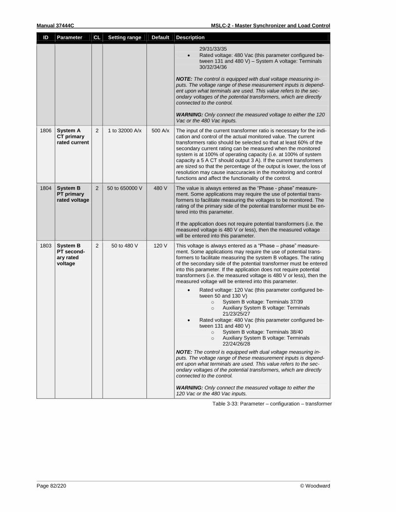
Manual 37444C MSLC-2 - Master Synchronizer and Load Control
Page 82/220 © Woodward
ID Parameter CL Setting range Default Description
29/31/33/35
Rated voltage: 480 Vac (this parameter configured be-tween 131 and 480 V) – System A voltage: Terminals 30/32/34/36
NOTE: The control is equipped with dual voltage measuring in-puts. The voltage range of these measurement inputs is depend-ent upon what terminals are used. This value refers to the sec-ondary voltages of the potential transformers, which are directly connected to the control. WARNING: Only connect the measured voltage to either the 120 Vac or the 480 Vac inputs.
1806 System A CT primary rated current
2 1 to 32000 A/x 500 A/x The input of the current transformer ratio is necessary for the indi-cation and control of the actual monitored value. The current transformers ratio should be selected so that at least 60% of the secondary current rating can be measured when the monitored system is at 100% of operating capacity (i.e. at 100% of system capacity a 5 A CT should output 3 A). If the current transformers are sized so that the percentage of the output is lower, the loss of resolution may cause inaccuracies in the monitoring and control functions and affect the functionality of the control.
1804 System B PT primary rated voltage
2 50 to 650000 V 480 V The value is always entered as the “Phase - phase” measure-ment. Some applications may require the use of potential trans-formers to facilitate measuring the voltages to be monitored. The rating of the primary side of the potential transformer must be en-tered into this parameter. If the application does not require potential transformers (i.e. the measured voltage is 480 V or less), then the measured voltage will be entered into this parameter.
1803 System B PT second-ary rated voltage
2 50 to 480 V 120 V This voltage is always entered as a “Phase – phase” measure-ment. Some applications may require the use of potential trans-formers to facilitate measuring the system B voltages. The rating of the secondary side of the potential transformer must be entered into this parameter. If the application does not require potential transformers (i.e. the measured voltage is 480 V or less), then the measured voltage will be entered into this parameter.
Rated voltage: 120 Vac (this parameter configured be-tween 50 and 130 V)
o System B voltage: Terminals 37/39 o Auxiliary System B voltage: Terminals
21/23/25/27
Rated voltage: 480 Vac (this parameter configured be-tween 131 and 480 V)
o System B voltage: Terminals 38/40 o Auxiliary System B voltage: Terminals
22/24/26/28
NOTE: The control is equipped with dual voltage measuring in-puts. The voltage range of these measurement inputs is depend-ent upon what terminals are used. This value refers to the sec-ondary voltages of the potential transformers, which are directly connected to the control. WARNING: Only connect the measured voltage to either the 120 Vac or the 480 Vac inputs.
Table 3-33: Parameter – configuration – transformer
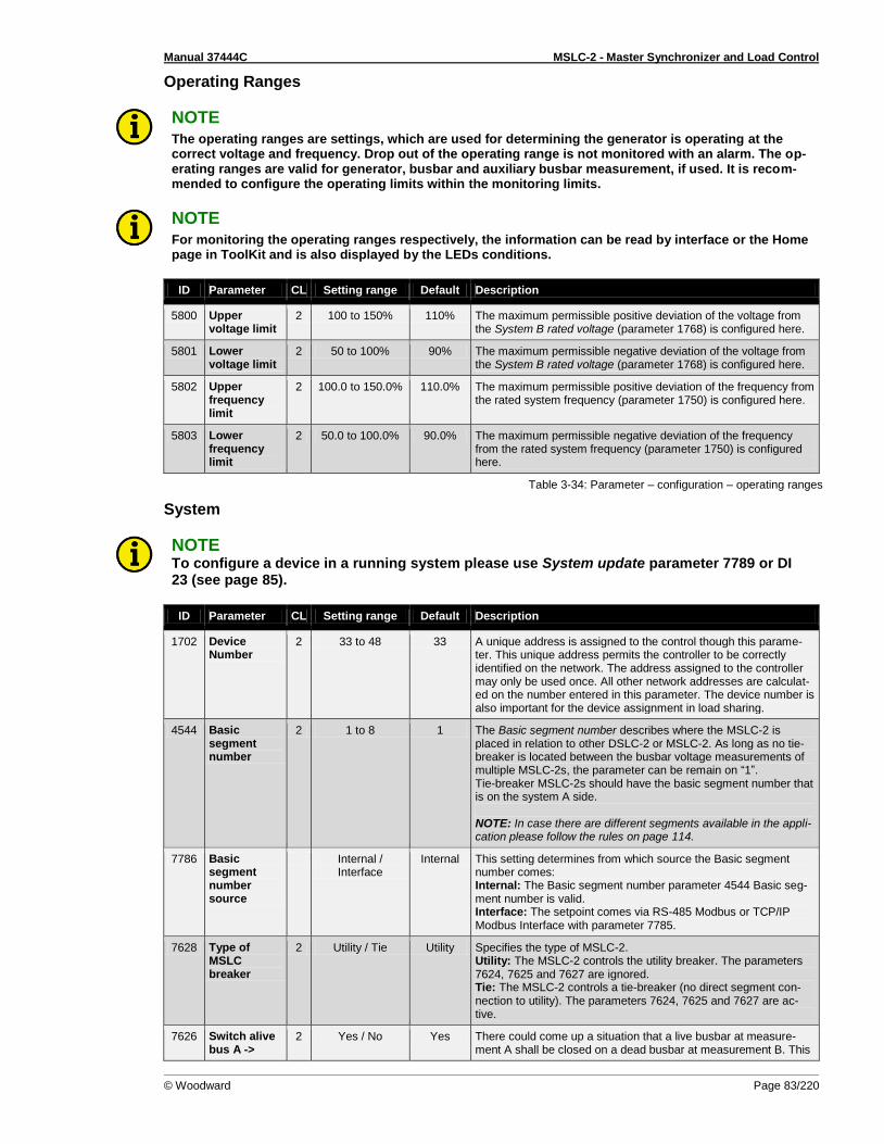
Manual 37444C MSLC-2 - Master Synchronizer and Load Control
© Woodward Page 83/220
Operating Ranges
NOTE The operating ranges are settings, which are used for determining the generator is operating at the correct voltage and frequency. Drop out of the operating range is not monitored with an alarm. The op-erating ranges are valid for generator, busbar and auxiliary busbar measurement, if used. It is recom-mended to configure the operating limits within the monitoring limits.
NOTE For monitoring the operating ranges respectively, the information can be read by interface or the Home page in ToolKit and is also displayed by the LEDs conditions.
ID Parameter CL Setting range Default Description
5800 Upper voltage limit
2 100 to 150% 110% The maximum permissible positive deviation of the voltage from the System B rated voltage (parameter 1768) is configured here.
5801 Lower voltage limit
2 50 to 100% 90% The maximum permissible negative deviation of the voltage from the System B rated voltage (parameter 1768) is configured here.
5802 Upper frequency limit
2 100.0 to 150.0% 110.0% The maximum permissible positive deviation of the frequency from the rated system frequency (parameter 1750) is configured here.
5803 Lower frequency limit
2 50.0 to 100.0% 90.0% The maximum permissible negative deviation of the frequency from the rated system frequency (parameter 1750) is configured here.
Table 3-34: Parameter – configuration – operating ranges
System
NOTE To configure a device in a running system please use System update parameter 7789 or DI 23 (see page 85).
ID Parameter CL Setting range Default Description
1702 Device Number
2 33 to 48 33 A unique address is assigned to the control though this parame-ter. This unique address permits the controller to be correctly identified on the network. The address assigned to the controller may only be used once. All other network addresses are calculat-ed on the number entered in this parameter. The device number is also important for the device assignment in load sharing.
4544 Basic segment number
2 1 to 8 1 The Basic segment number describes where the MSLC-2 is placed in relation to other DSLC-2 or MSLC-2. As long as no tie-breaker is located between the busbar voltage measurements of multiple MSLC-2s, the parameter can be remain on “1”. Tie-breaker MSLC-2s should have the basic segment number that is on the system A side. NOTE: In case there are different segments available in the appli-cation please follow the rules on page 114.
7786 Basic segment number source
Internal / Interface
Internal This setting determines from which source the Basic segment number comes: Internal: The Basic segment number parameter 4544 Basic seg-ment number is valid. Interface: The setpoint comes via RS-485 Modbus or TCP/IP Modbus Interface with parameter 7785.
7628 Type of MSLC breaker
2 Utility / Tie Utility Specifies the type of MSLC-2. Utility: The MSLC-2 controls the utility breaker. The parameters 7624, 7625 and 7627 are ignored. Tie: The MSLC-2 controls a tie-breaker (no direct segment con-nection to utility). The parameters 7624, 7625 and 7627 are ac-tive.
7626 Switch alive bus A ->
2 Yes / No Yes There could come up a situation that a live busbar at measure-ment A shall be closed on a dead busbar at measurement B. This
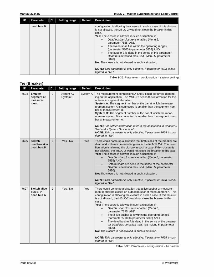
Manual 37444C MSLC-2 - Master Synchronizer and Load Control
Page 84/220 © Woodward
ID Parameter CL Setting range Default Description
dead bus B configuration is allowing the closure in such a case. If this closure is not allowed, the MSLC-2 would not close the breaker in this case. Yes: The closure is allowed in such a situation, if:
Dead busbar closure is enabled (Menu 5, parameter 7555) AND
The live busbar A is within the operating ranges (parameter 5800 to parameter 5803) AND
The busbar B is dead in the sense of the parameter Dead bus detection max. volt. (Menu 5, parameter 5820).
No: The closure is not allowed in such a situation. NOTE: This parameter is only effective, if parameter 7628 is con-figured to "Tie".
Table 3-35: Parameter – configuration – system settings
Tie (Breaker)
ID Parameter CL Setting range Default Description
7624 Smaller segment at measure-ment
2 System A / System B
System A The measurement connections A and B could be turned depend-ing on the application. The MSLC-2 needs this information for the automatic segment allocation. System A: The segment number of the bar at which the meas-urement system A is connected is smaller than the segment num-ber at measurement B. System B: The segment number of the bar at which the meas-urement system B is connected is smaller than the segment num-ber at measurement A. NOTE: For further information refer to the description in Chapter 8 “Network / System Description”. NOTE: This parameter is only effective, if parameter 7628 is con-figured to "Tie".
7625 Switch deadbus A -> dead bus B
2 Yes / No Yes There could come up a situation that both sides of the breaker are dead and a close command is given to the tie MSLC-2. This con-figuration is allowing the closure in such a case. If this closure is not allowed, the MSLC-2 would not close the breaker in this case. Yes: The closure is allowed in such a situation, if:
Dead busbar closure is enabled (Menu 5, parameter 7555) AND
Both busbars are dead in the sense of the parameter Dead bus detection max. volt. (Menu 5, parameter 5820).
No: The closure is not allowed in such a situation. NOTE: This parameter is only effective, if parameter 7628 is con-figured to "Tie".
7627 Switch alive bus B -> dead bus A
2 Yes / No Yes There could come up a situation that a live busbar at measure-ment B shall be closed on a dead busbar at measurement A. This configuration is allowing the closure in such a case. If this closure is not allowed, the MSLC-2 would not close the breaker in this case. Yes: The closure is allowed in such a situation, if:
Dead busbar closure is enabled (Menu 5, parameter 7555) AND
The a live busbar B is within the operating ranges (parameter 5800 to parameter 5803) AND
The dead busbar A is dead in the sense of the parame-ter Dead bus detection max. volt. (Menu 5, parameter 5820).
No: The closure is not allowed in such a situation. NOTE: This parameter is only effective, if parameter 7628 is con-figured to "Tie".
Table 3-36: Parameter – configuration – tie breaker

Manual 37444C MSLC-2 - Master Synchronizer and Load Control
© Woodward Page 85/220
Communication
ID Parameter CL Setting range Default Description
7809 Ethernet communica-tion mode
2 Single / Redun-dant
Single Single: Network A for UDP messages and Network B for TCP/IP communication Redundant: Network A and Network B are for UDP messages and for TCP/IP communication. If one network fails an alarm will be initiated.
7789 System up-date
2 Off / On Off Adding or removing the device can be started
Table 3-37: Parameter – configuration – communication
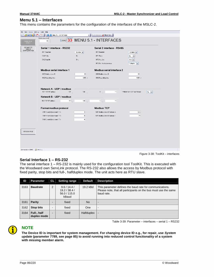
Manual 37444C MSLC-2 - Master Synchronizer and Load Control
Page 86/220 © Woodward
Menu 5.1 – Interfaces This menu contains the parameters for the configuration of the interfaces of the MSLC-2.
Figure 3-38: ToolKit – interfaces
Serial Interface 1 – RS-232 The serial interface 1 – RS-232 is mainly used for the configuration tool ToolKit. This is executed with the Woodward own ServLink protocol. The RS-232 also allows the access by Modbus protocol with fixed parity, stop bits and full-, halfduplex mode. The unit acts here as RTU slave.
ID Parameter CL Setting range Default Description
3163 Baudrate 2 9.6 / 14.4 / 19.2 / 38.4 / 56.0 / 115.0
kBaud
19.2 kBd This parameter defines the baud rate for communications. Please note, that all participants on the bus must use the same baud rate.
3161 Parity - fixed No -
3162 Stop bits - fixed One -
3164 Full-, half duplex mode
- fixed Halfduplex -
Table 3-39: Parameter – interfaces – serial 1 – RS232
NOTE The Device ID is important for system management. For changing device ID e.g., for repair, use System update (parameter 7789, see page 85) to avoid running into reduced control functionality of a system with missing member alarm.

Manual 37444C MSLC-2 - Master Synchronizer and Load Control
© Woodward Page 87/220
Modbus Serial Interface 1
ID Parameter CL Setting range Default Description
3185 Modbus slave ID
2 0 to 255 1 The Modbus device address, which is used to identify the device via Modbus, is entered here. If "0" is configured here, the Modbus is disabled.
3186 Reply delay time
2 0.00 to 1.00 s 0.00 s This is the minimum delay time between a request from the Mod-bus master and the response of the slave. This time is also re-quired if an external interface converter to RS-485 is used for ex-ample.
Table 3-40: Parameter – interfaces – serial 1 – Modbus
Serial Interface 2 – RS-485 The serial interface 2 – RS-485 allows exclusively access by Modbus protocol with configurable parity, stop bits and full-, halfduplex mode. The unit acts here as a RTU slave.
ID Parameter CL Setting range Default Description
3170 Baudrate 2 9.6 / 14.4 / 19.2 / 38.4 / 56.0 / 115.0
kBaud
19.2 kBd This parameter defines the baud rate for communications. Please note, that all participants on the bus must use the same baud rate.
3171 Parity 2 No / Even / Odd No The used parity of the interface is set here.
3172 Stop bits 2 One / Two One The number of stop bits is set here.
3173 Full-, halfduplex mode
2 Fullduplex / Halfduplex
Fullduplex Fullduplex: Fullduplex mode is enabled. Halfduplex: Halfduplex mode is enabled.
Table 3-41: Parameter – interfaces – serial 2 – RS485
Modbus Serial Interface 2
ID Parameter CL Setting range Default Description
3188 Modbus slave ID
2 0 to 255 1 The Modbus device address, which is used to identify the device via Modbus, is entered here. If "0" is configured here, the Modbus is disabled.
3189 Reply delay time
2 0.00 to 2.55 s 0.00 s This is the minimum delay time between a request from the Mod-bus master and the set response of the slave. This time is re-quired in halfduplex mode.
Table 3-42: Parameter – interfaces – serial 2 – Modbus
Network A – UDP / Modbus The network A – UDP Ethernet bus is reserved for internal communication between all DSLC-2 and MSLC-2 in one system independent on the busbar segment. Up to 32 DSLC-2 and up to 16 MSLC-2 can communicate over the 100ms – UDP messages. The network A – Modbus/TCP Ethernet bus is provided for external communication purposes between all DSLC-2 and MSLC-2 in one system and a PLC. Up to 10 TCP/IP stacks can be built up per unit.
ID Parameter CL Setting range Default Description
5330 TCP/IP address
2 Info 192.168. 0.33
Ethernet Channel Network A: Type UDP./ Modbus /TCP A PLC can be able to open up to 64 Modbus/TCP channels The IP address of Channel A is fixed to: 192.168.0.Device-ID, where Device-ID = 33 to 48 for MSLC-2.
NOTE: In this field is usually entered the device number of the unit (parameter 1702).
Table 3-43: Parameter – interfaces – network A
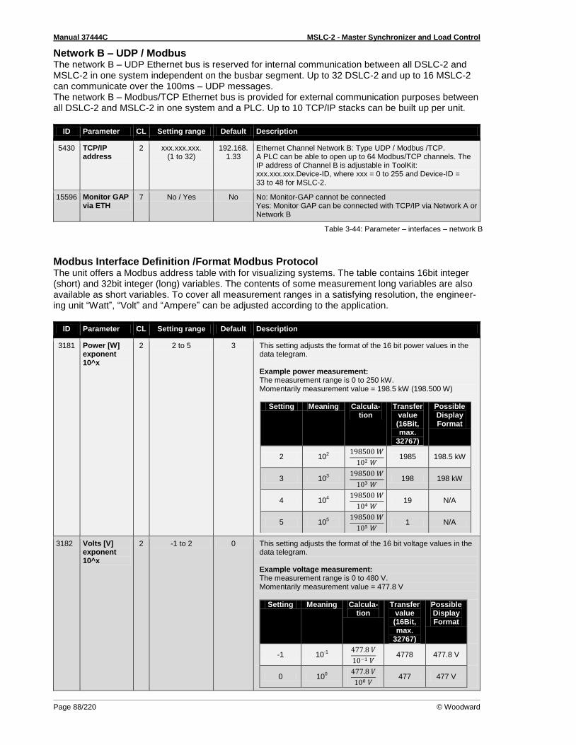
Manual 37444C MSLC-2 - Master Synchronizer and Load Control
Page 88/220 © Woodward
Network B – UDP / Modbus The network B – UDP Ethernet bus is reserved for internal communication between all DSLC-2 and MSLC-2 in one system independent on the busbar segment. Up to 32 DSLC-2 and up to 16 MSLC-2 can communicate over the 100ms – UDP messages. The network B – Modbus/TCP Ethernet bus is provided for external communication purposes between all DSLC-2 and MSLC-2 in one system and a PLC. Up to 10 TCP/IP stacks can be built up per unit.
ID Parameter CL Setting range Default Description
5430 TCP/IP address
2 xxx.xxx.xxx. (1 to 32)
192.168. 1.33
Ethernet Channel Network B: Type UDP / Modbus /TCP. A PLC can be able to open up to 64 Modbus/TCP channels. The IP address of Channel B is adjustable in ToolKit: xxx.xxx.xxx.Device-ID, where xxx = 0 to 255 and Device-ID = 33 to 48 for MSLC-2.
15596 Monitor GAP via ETH
7 No / Yes No No: Monitor-GAP cannot be connected Yes: Monitor GAP can be connected with TCP/IP via Network A or Network B
Table 3-44: Parameter – interfaces – network B
Modbus Interface Definition /Format Modbus Protocol The unit offers a Modbus address table with for visualizing systems. The table contains 16bit integer (short) and 32bit integer (long) variables. The contents of some measurement long variables are also available as short variables. To cover all measurement ranges in a satisfying resolution, the engineer-ing unit “Watt”, “Volt” and “Ampere” can be adjusted according to the application.
ID Parameter CL Setting range Default Description
3181 Power [W] exponent 10^x
2 2 to 5 3 This setting adjusts the format of the 16 bit power values in the data telegram. Example power measurement: The measurement range is 0 to 250 kW. Momentarily measurement value = 198.5 kW (198.500 W)
Setting Meaning Calcula-tion
Transfer value (16Bit, max.
32767)
Possible Display Format
2 102
1985 198.5 kW
3 103
198 198 kW
4 104
19 N/A
5 105
1 N/A
3182 Volts [V] exponent 10^x
2 -1 to 2 0 This setting adjusts the format of the 16 bit voltage values in the data telegram. Example voltage measurement: The measurement range is 0 to 480 V. Momentarily measurement value = 477.8 V
Setting Meaning Calcula-tion
Transfer value (16Bit, max.
32767)
Possible Display Format
-1 10-1
4778 477.8 V
0 100
477 477 V

Manual 37444C MSLC-2 - Master Synchronizer and Load Control
© Woodward Page 89/220
ID Parameter CL Setting range Default Description
1 101
47 N/A
2 102
4 N/A
3183 Current [A] exponent 10^x
2 -1 to 0 0 This setting adjusts the format of the 16 bit current values in the data telegram. Example current measurement: The measurement range is 0 to 500 A Momentarily measurement value = 345.4 A
Setting Meaning Calcula-tion
Transfer value (16Bit, max.
32767)
Possible Display Format
-1 10-1
3454 345.4 A
0 100
345 345 A
Table 3-45: Parameter – interfaces – format Modbus protocol
Modbus TCP There are two Modbus TCP Slave IDs.
ID Parameter CL Setting range Default Description
5351 Modbus slave ID net-work A
2 0 to 255 255 Modbus TCP slave ID for Network A Modbus connections
5451 Modbus slave ID net-work B
2 0 to 255 255 Modbus TCP slave ID for Network B Modbus connections
Table 3-46: Parameter – interfaces – Modbus TCP
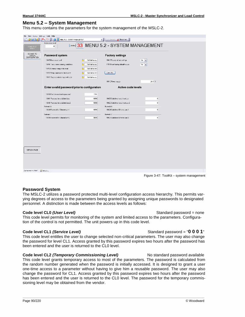
Manual 37444C MSLC-2 - Master Synchronizer and Load Control
Page 90/220 © Woodward
Menu 5.2 – System Management This menu contains the parameters for the system management of the MSLC-2.
Figure 3-47: ToolKit – system management
Password System The MSLC-2 utilizes a password protected multi-level configuration access hierarchy. This permits var-ying degrees of access to the parameters being granted by assigning unique passwords to designated personnel. A distinction is made between the access levels as follows: Code level CL0 (User Level) Standard password = none This code level permits for monitoring of the system and limited access to the parameters. Configura-tion of the control is not permitted. The unit powers up in this code level.
Code level CL1 (Service Level) Standard password = "0 0 0 1"
This code level entitles the user to change selected non-critical parameters. The user may also change the password for level CL1. Access granted by this password expires two hours after the password has been entered and the user is returned to the CL0 level. Code level CL2 (Temporary Commissioning Level) No standard password available This code level grants temporary access to most of the parameters. The password is calculated from the random number generated when the password is initially accessed. It is designed to grant a user one-time access to a parameter without having to give him a reusable password. The user may also change the password for CL1. Access granted by this password expires two hours after the password has been entered and the user is returned to the CL0 level. The password for the temporary commis-sioning level may be obtained from the vendor.
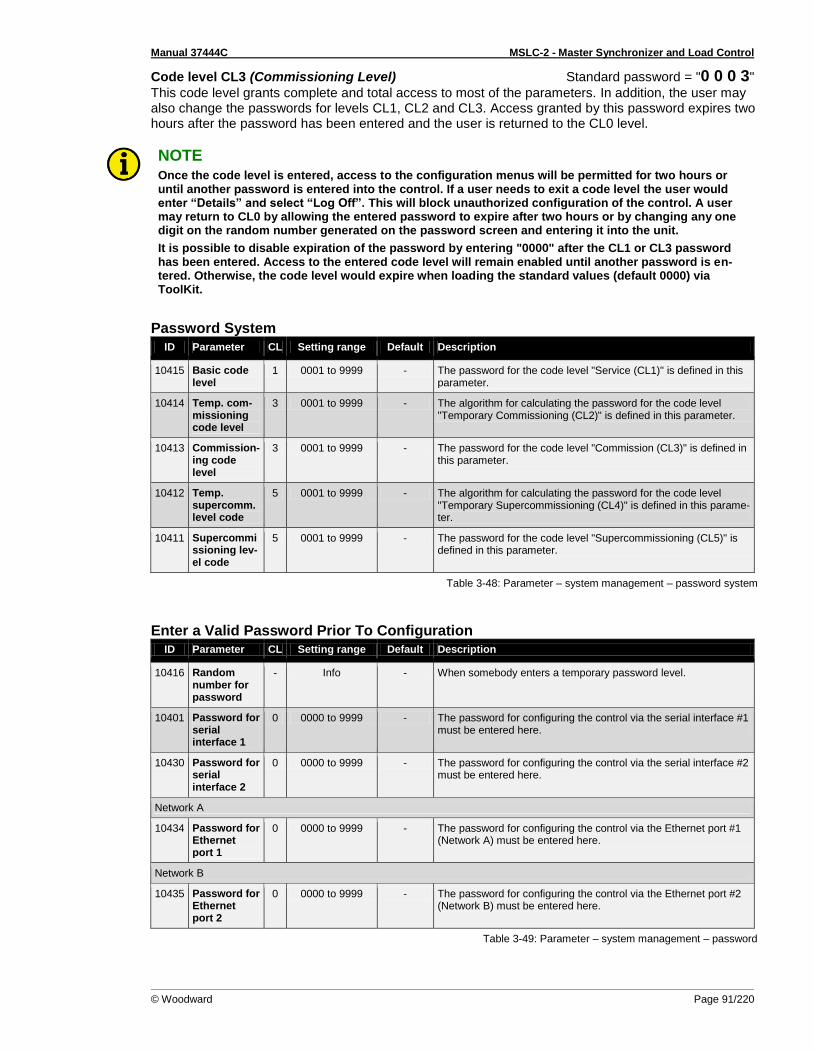
Manual 37444C MSLC-2 - Master Synchronizer and Load Control
© Woodward Page 91/220
Code level CL3 (Commissioning Level) Standard password = "0 0 0 3"
This code level grants complete and total access to most of the parameters. In addition, the user may also change the passwords for levels CL1, CL2 and CL3. Access granted by this password expires two hours after the password has been entered and the user is returned to the CL0 level.
NOTE Once the code level is entered, access to the configuration menus will be permitted for two hours or until another password is entered into the control. If a user needs to exit a code level the user would enter “Details” and select “Log Off”. This will block unauthorized configuration of the control. A user may return to CL0 by allowing the entered password to expire after two hours or by changing any one digit on the random number generated on the password screen and entering it into the unit.
It is possible to disable expiration of the password by entering "0000" after the CL1 or CL3 password has been entered. Access to the entered code level will remain enabled until another password is en-tered. Otherwise, the code level would expire when loading the standard values (default 0000) via ToolKit.
Password System
ID Parameter CL Setting range Default Description
10415 Basic code level
1 0001 to 9999 - The password for the code level "Service (CL1)" is defined in this parameter.
10414 Temp. com-missioning code level
3 0001 to 9999 - The algorithm for calculating the password for the code level "Temporary Commissioning (CL2)" is defined in this parameter.
10413 Commission-ing code level
3 0001 to 9999 - The password for the code level "Commission (CL3)" is defined in this parameter.
10412 Temp. supercomm. level code
5 0001 to 9999 - The algorithm for calculating the password for the code level "Temporary Supercommissioning (CL4)" is defined in this parame-ter.
10411 Supercommissioning lev-el code
5 0001 to 9999 - The password for the code level "Supercommissioning (CL5)" is defined in this parameter.
Table 3-48: Parameter – system management – password system
Enter a Valid Password Prior To Configuration
ID Parameter CL Setting range Default Description
10416 Random number for password
- Info - When somebody enters a temporary password level.
10401 Password for serial interface 1
0 0000 to 9999 - The password for configuring the control via the serial interface #1 must be entered here.
10430 Password for serial interface 2
0 0000 to 9999 - The password for configuring the control via the serial interface #2 must be entered here.
Network A
10434 Password for Ethernet port 1
0 0000 to 9999 - The password for configuring the control via the Ethernet port #1 (Network A) must be entered here.
Network B
10435 Password for Ethernet port 2
0 0000 to 9999 - The password for configuring the control via the Ethernet port #2 (Network B) must be entered here.
Table 3-49: Parameter – system management – password

Manual 37444C MSLC-2 - Master Synchronizer and Load Control
Page 92/220 © Woodward
Active Code Levels
ID Parameter CL Setting range Default Description
10406 Code level serial interface 1
- Info - This value displays the code level, which is currently enabled for
access via RS-232 serial interface #1.
10420 Code level serial interface 2
- Info - This value displays the code level, which is currently enabled for access via RS-485 serial interface #2.
Network A
10424 Code level Ethernet port 1
- Info - This value displays the code level, which is currently enabled for access via Ethernet port #1 (Network A).
Network B
10425 Code level Ethernet port 2
- Info - This value displays the code level, which is currently enabled for access via Ethernet port #2 (Network B).
Table 3-50: Parameter – system management – active code levels
Factory Settings
ID Parameter CL Setting range Default Description
10417 Factory default settings
0 No / Yes No Selecting “Yes” will allow the reset back to Factory default settings by selecting “Yes” for the Reset factory default values parameter (parameter 1701).
1701 Reset factory default values
0 No / Yes No No: All parameters will remain as currently configured. Yes: All parameters, which the enabled access code grants privi-leges to, will be restored to factory default values. This value re-turns to “No” when factory defaults are set.
Table 3-51: Parameter – system management – factory settings
Lamp Test (Button) Push this button to illuminate all lights on the controller. Correct LED operation can be checked.
Power Supply
ID Parameter CL Setting range Default Description
10110 Power sup-ply
0 - - Display of the measured supply voltage in V
Table 3-52: Parameter – system management – power supply
Menu 5.3 – Configure Counters This menu contains the parameters for the Configuration of the Counters of the MSLC-2.
Figure 3-53: ToolKit – configure counters

Manual 37444C MSLC-2 - Master Synchronizer and Load Control
© Woodward Page 93/220
System A reset values
ID Parameter CL Setting range Default Description
2515 Counter val-ue present
2 0 to 999,999,99
[0] This value is utilized to set the following counters:
operation hours counter
kWh counter
kvarh counter The number entered into this parameter is the number that will be set to the parameters listed above when they are enabled.
2510 Syst. A active power [0.00 MWh]
2 Yes / No [No] Yes: The current value of this counter is overwritten with the value configured in "Counter value preset" (parameter 2515). After the counter has been (re)set, this parameter changes back to "No" automatically. No: The value of this counter is not changed. Example
The counter value preset (parameter 2515) is config-ured to "3456".
If this parameter is set to "Yes", the "System A active power" counter will be set to 34.56 MWh.
2511 Syst. A react. power [0.00 Mvarh]
2 Yes / No [No] Yes: The current value of this counter is overwritten with the value configured in "Counter value preset" (parameter 2515). After the counter has been (re)set, this parameter changes back to "No" automatically. No: The value of this counter is not changed. Example
The counter value preset (parameter 2515) is config-ured to "3456".
If this parameter is set to "Yes", the " System A reactive power" counter will be set to 34.56 Mvarh.
2512 Syst. A -active power [0.00 MWh]
2 Yes / No [No] Yes: The current value of this counter is overwritten with the value configured in "Counter value preset" (parameter 2515). After the counter has been (re)set, this parameter changes back to "No" automatically. No: The value of this counter is not changed. Example
The counter value preset (parameter 2515) is config-ured to "3456".
If this parameter is set to "Yes", the "System A -active power" counter will be set to 34.56 MWh.
2513 Syst. A -react. power [0.00 Mvarh]
2 Yes / No [No] Yes: The current value of this counter is overwritten with the value configured in "Counter value preset" (parameter 2515). After the counter has been (re)set, this parameter changes back to "No" automatically. No: The value of this counter is not changed. Example
The counter value preset (parameter 2515) is config-ured to "3456".
If this parameter is set to "Yes", the " System A -reactive power" counter will be set to 34.56 Mvarh.
Table 3-54: Parameter – configure counters

Manual 37444C MSLC-2 - Master Synchronizer and Load Control
Page 94/220 © Woodward
Menu 6 – Analog Inputs This menu contains the parameters for the configuration of the analog inputs of the MSLC-2.
Figure 3-55: ToolKit – analog inputs
Remote Load Reference Input / Process Reference Input This analog input can be used for two functionalities: 1. Remote load reference input. The input becomes active, if the DI “Setpoint Raise” / “Setpoint Low-
er” (remote) are closed and the DI “Base Load” or “Imp/Exp Control” is closed.
Figure 3-56: ToolKit – relevant fields for remote load reference input
The load control interacts with the percentage input value shown in field Remote reference input (parameter 10177). The setting on the right side is the scaling for a minimum and maximum load value while displaying the actual kW setting, which is shown in the field Remote load reference in-put (parameter 7738).
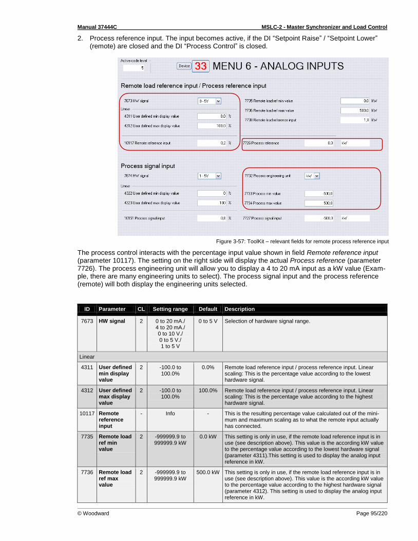
Manual 37444C MSLC-2 - Master Synchronizer and Load Control
© Woodward Page 95/220
2. Process reference input. The input becomes active, if the DI “Setpoint Raise” / “Setpoint Lower” (remote) are closed and the DI “Process Control” is closed.
Figure 3-57: ToolKit – relevant fields for remote process reference input
The process control interacts with the percentage input value shown in field Remote reference input (parameter 10117). The setting on the right side will display the actual Process reference (parameter 7726). The process engineering unit will allow you to display a 4 to 20 mA input as a kW value (Exam-ple, there are many engineering units to select). The process signal input and the process reference (remote) will both display the engineering units selected.
ID Parameter CL Setting range Default Description
7673 HW signal 2 0 to 20 mA./ 4 to 20 mA./ 0 to 10 V./ 0 to 5 V./ 1 to 5 V
0 to 5 V Selection of hardware signal range.
Linear
4311 User defined min display value
2 -100.0 to 100.0%
0.0% Remote load reference input / process reference input. Linear scaling: This is the percentage value according to the lowest hardware signal.
4312 User defined max display value
2 -100.0 to 100.0%
100.0% Remote load reference input / process reference input. Linear scaling: This is the percentage value according to the highest hardware signal.
10117 Remote reference input
- Info - This is the resulting percentage value calculated out of the mini-mum and maximum scaling as to what the remote input actually has connected.
7735 Remote load ref min value
2 -999999.9 to 999999.9 kW
0.0 kW This setting is only in use, if the remote load reference input is in use (see description above). This value is the according kW value to the percentage value according to the lowest hardware signal (parameter 4311).This setting is used to display the analog input reference in kW.
7736 Remote load ref max value
2 -999999.9 to 999999.9 kW
500.0 kW This setting is only in use, if the remote load reference input is in use (see description above). This value is the according kW value to the percentage value according to the highest hardware signal (parameter 4312). This setting is used to display the analog input reference in kW.
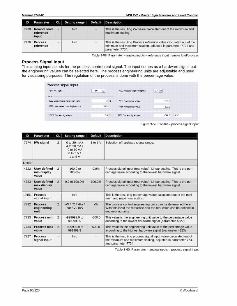
Manual 37444C MSLC-2 - Master Synchronizer and Load Control
Page 96/220 © Woodward
ID Parameter CL Setting range Default Description
7738 Remote load reference input
- Info - This is the resulting kW value calculated out of the minimum and maximum scaling.
7726 Process reference
- Info - This is the resulting Process reference value calculated out of the minimum and maximum scaling, adjusted in parameter 7733 and parameter 7734.
Table 3-58: Parameter – analog inputs – reference input: remote load/process
Process Signal Input This analog input stands for the process control real signal. The input comes as a hardware signal but the engineering values can be selected here. The process engineering units are adjustable and used for visualizing purposes. The regulation of the process is done with the percentage value.
Figure 3-59: ToolKit – process signal input
ID Parameter CL Setting range Default Description
7674 HW signal 2 0 to 20 mA./ 4 to 20 mA./ 0 to 10 V./ 0 to 5 V./ 1 to 5 V
1 to 5 V Selection of hardware signal range.
Linear
4322 User defined min display value
2 -100.0 to 100.0%
0.0% Process signal input (real value). Linear scaling: This is the per-centage value according to the lowest hardware signal.
4323 User defined max display value
2 0.0 to 100.0% 100.0% Process signal input (real value). Linear scaling: This is the per-centage value according to the lowest hardware signal.
10151 Process signal input
- Info - This is the resulting percentage value calculated out of the mini-mum and maximum scaling.
7732 Process engineering unit
2 kW / °C / kPa / bar / V / mA
kW The process control engineering units can be determined here. With this input the reference and the real value can be defined in engineering units.
7733 Process min value
2 -999999.9 to 999999.9
-500.0 This value is the engineering unit value to the percentage value according to the lowest hardware signal (parameter 4322).
7734 Process max value
2 -999999.9 to 999999.9
500.0 This value is the engineering unit value to the percentage value according to the highest hardware signal (parameter 4323).
7727 Process signal Input
- Info - This is the resulting process signal input value calculated out of the minimum and maximum scaling, adjusted in parameter 7733 and parameter 7734.
Table 3-60: Parameter – analog inputs – process signal input

Manual 37444C MSLC-2 - Master Synchronizer and Load Control
© Woodward Page 97/220
Reactive Load Input This analog input stands for the power factor reference signal. Remote var reference control is not available at this time. To activate the remote reactive load input, the discrete inputs “Voltage raise” and “Voltage lower” must be closed.
Figure 3-61: ToolKit – reactive load input
ID Parameter CL Setting range Default Description
7675 HW signal 2 0 to 20 mA./ 4 to 20 mA./ 0 to 10 V./ 0 to 5 V./ 1 to 5 V
0 to 5 V Selection of hardware signal range.
Linear
4333 User defined min display value
2 -0.999 to 0.999 PF
-0.500 PF Power factor reference signal input. Linear scaling: This is the power factor value according to the lowest hardware signal.
4334 User defined max display value
2 -0.999 to 0.999 PF
0.500 PF Power factor reference signal input. Linear scaling: This is the power factor value according to the highest hardware signal.
7718 Reactive load input
- Info - This is the resulting power factor reference calculated out of the minimum and maximum scaling, adjusted in parameter 4333 and parameter 4334.
Table 3-62: Parameter – analog inputs – reactive load input

Manual 37444C MSLC-2 - Master Synchronizer and Load Control
Page 98/220 © Woodward
Menu 7, 7.1 and 7.2 – Electrical Parameters This menu contains the general electrical parameters of the MSLC-2.
Figure 3-63: ToolKit – electrical parameters
Menu 7, 7.1, and 7.2 provide all the AC measurement, voltage, current, power and reactive power. The System A (menu 7.1) is always a 3-phase measurement and the System B (menu 7.2) is measured as a single phase. A configuration in Menu 5, Auxiliary system B available (parameter 7649), allows addi-tionally the measurement of the system B with 3 phases. The option of the 3-phase system B meas-urement allows the monitoring of all 3 phases and detection of the system B phase rotation. Menu 7 will display the auxiliary system B measurement values when parameter 7649 is configured to “Yes”.
Menu 7.1 – System A
Figure 3-64: ToolKit – electrical parameters System A
Active Power
ID Parameter CL Setting range Format Description
135 System A active power
- Info 0.0 kW Display of System A active power in kW.
4622 System A active power
- Info 0% Display of System A active power in%.
Table 3-65: Parameter – System A – active power
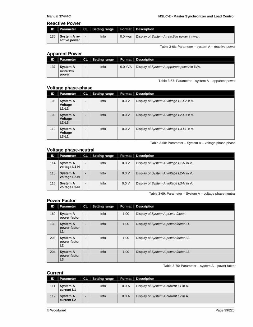
Manual 37444C MSLC-2 - Master Synchronizer and Load Control
© Woodward Page 99/220
Reactive Power
ID Parameter CL Setting range Format Description
136 System A re-active power
- Info 0.0 kvar Display of System A reactive power in kvar.
Table 3-66: Parameter – system A – reactive power
Apparent Power
ID Parameter CL Setting range Format Description
137 System A apparent power
- Info 0.0 kVA Display of System A apparent power in kVA.
Table 3-67: Parameter – system A – apparent power
Voltage phase-phase
ID Parameter CL Setting range Format Description
108 System A Voltage L1-L2
- Info 0.0 V Display of System A voltage L1-L2 in V.
109 System A Voltage L2-L3
- Info 0.0 V Display of System A voltage L2-L3 in V.
110 System A Voltage L3-L1
- Info 0.0 V Display of System A voltage L3-L1 in V.
Table 3-68: Parameter – System A – voltage phase-phase
Voltage phase-neutral
ID Parameter CL Setting range Format Description
114 System A voltage L1-N
- Info 0.0 V Display of System A voltage L1-N in V.
115 System A voltage L2-N
- Info 0.0 V Display of System A voltage L2-N in V.
116 System A voltage L3-N
- Info 0.0 V Display of System A voltage L3-N in V.
Table 3-69: Parameter – System A – voltage phase-neutral
Power Factor
ID Parameter CL Setting range Format Description
160 System A power factor
- Info 1.00 Display of System A power factor.
139 System A power factor L1
- Info 1.00 Display of System A power factor L1.
203 System A power factor L2
- Info 1.00 Display of System A power factor L2.
204 System A power factor L3
- Info 1.00 Display of System A power factor L3.
Table 3-70: Parameter – system A – power factor
Current
ID Parameter CL Setting range Format Description
111 System A current L1
- Info 0.0 A Display of System A current L1 in A.
112 System A current L2
- Info 0.0 A Display of System A current L2 in A.
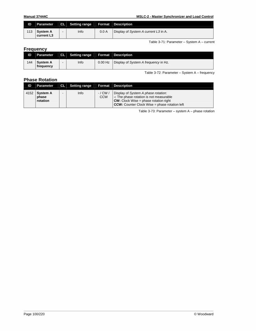
Manual 37444C MSLC-2 - Master Synchronizer and Load Control
Page 100/220 © Woodward
ID Parameter CL Setting range Format Description
113 System A current L3
- Info 0.0 A Display of System A current L3 in A.
Table 3-71: Parameter – System A – current
Frequency
ID Parameter CL Setting range Format Description
144 System A frequency
- Info 0.00 Hz Display of System A frequency in Hz.
Table 3-72: Parameter – System A – frequency
Phase Rotation
ID Parameter CL Setting range Format Description
4152 System A phase rotation
- Info - / CW / CCW
Display of System A phase rotation: -: The phase rotation is not measurable CW: Clock Wise = phase rotation right CCW: Counter Clock Wise = phase rotation left
Table 3-73: Parameter – system A – phase rotation
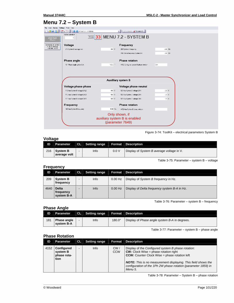
Manual 37444C MSLC-2 - Master Synchronizer and Load Control
© Woodward Page 101/220
Menu 7.2 – System B
Figure 3-74: ToolKit – electrical parameters System B
Voltage
ID Parameter CL Setting range Format Description
216 System B average volt
- Info 0.0 V Display of System B average voltage in V.
Table 3-75: Parameter – system B – voltage
Frequency
ID Parameter CL Setting range Format Description
209 System B frequency
- Info 0.00 Hz Display of System B frequency in Hz.
4640 Delta frequency system B-A
- Info 0.00 Hz Display of Delta frequency system B-A in Hz.
Table 3-76: Parameter – system B – frequency
Phase Angle
ID Parameter CL Setting range Format Description
181 Phase angle system B-A
- Info 180.0° Display of Phase angle system B-A in degrees.
Table 3-77: Parameter – system B – phase angle
Phase Rotation
ID Parameter CL Setting range Format Description
4152 Configured system B phase rota-tion
- Info CW / CCW
Display of the Configured system B phase rotation: CW: Clock Wise = phase rotation right CCW: Counter Clock Wise = phase rotation left NOTE: This is no measurement displaying. This field shows the configuration of the 1Ph 2W phase rotation (parameter 1859) in Menu 5.
Table 3-78: Parameter – System B – phase rotation
Only shown, if auxiliary system B is enabled
(parameter 7649)

Manual 37444C MSLC-2 - Master Synchronizer and Load Control
Page 102/220 © Woodward
Auxiliary System B Measurement (depends on parameter 7649 Auxiliary System B available)
Voltage phase-phase (Aux. System B)
ID Parameter CL Setting range Format Description
118 Aux System B voltage L1-L2
- Info 0.0 V Display of Auxiliary System B voltage L1-L2 in V.
119 Aux System B voltage L2-L3
- Info 0.0 V Display of Auxiliary System B voltage L2-L3 in V.
120 Aux System B voltage L3-L1
- Info 0.0 V Display of Auxiliary System B voltage L3-L1 in V.
Table 3-79: Parameter – aux. system B – voltage phase-phase
Voltage phase-neutral (Aux. System B)
ID Parameter CL Setting range Format Description
121 Aux System B voltage L1-N
- Info 0.0 V Display of Auxiliary System B voltage L1-N in V.
122 Aux System B voltage L2-N
- Info 0.0 V Display of Auxiliary System B voltage L2-N in V.
123 Aux System B voltage L3-N
- Info 0.0 V Display of Auxiliary System B voltage L3-N in V.
Table 3-80: Parameter – aux. system B – voltage phase-neutral
Frequency (Aux. System B)
ID Parameter CL Setting range Format Description
147 Aux System B frequency
- Info 0.00 Hz Display of Auxiliary System B frequency in Hz.
Table 3-81: Parameter – aux. system B – frequency
Phase Rotation (Aux. System B)
ID Parameter CL Setting range Format Description
4152 Aux System B phase rotation
- Info - / CW / CCW
Display of Auxiliary System B phase rotation: -: The phase rotation is not measurable CW: Clock Wise = phase rotation right CCW: Counter Clock Wise = phase rotation left
Table 3-82: Parameter – auxiliary system B – phase rotation
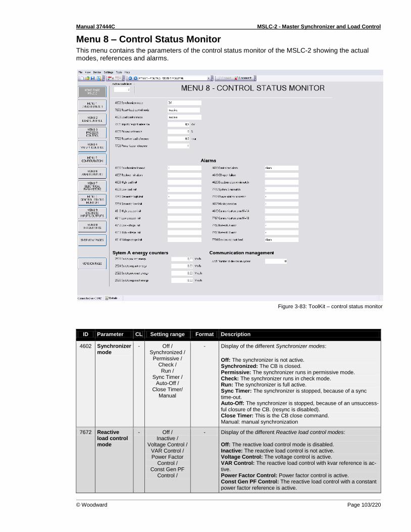
Manual 37444C MSLC-2 - Master Synchronizer and Load Control
© Woodward Page 103/220
Menu 8 – Control Status Monitor This menu contains the parameters of the control status monitor of the MSLC-2 showing the actual modes, references and alarms.
Figure 3-83: ToolKit – control status monitor
ID Parameter CL Setting range Format Description
4602 Synchronizer mode
- Off / Synchronized /
Permissive / Check / Run /
Sync Timer / Auto-Off /
Close Timer/ Manual
- Display of the different Synchronizer modes:
Off: The synchronizer is not active. Synchronized: The CB is closed. Permissive: The synchronizer runs in permissive mode. Check: The synchronizer runs in check mode. Run: The synchronizer is full active. Sync Timer: The synchronizer is stopped, because of a sync time-out. Auto-Off: The synchronizer is stopped, because of an unsuccess-ful closure of the CB. (resync is disabled). Close Timer: This is the CB close command. Manual: manual synchronization
7672 Reactive load control mode
- Off / Inactive /
Voltage Control / VAR Control / Power Factor
Control / Const Gen PF
Control /
- Display of the different Reactive load control modes: Off: The reactive load control mode is disabled. Inactive: The reactive load control is not active. Voltage Control: The voltage control is active. VAR Control: The reactive load control with kvar reference is ac-tive. Power Factor Control: Power factor control is active. Const Gen PF Control: The reactive load control with a constant power factor reference is active.
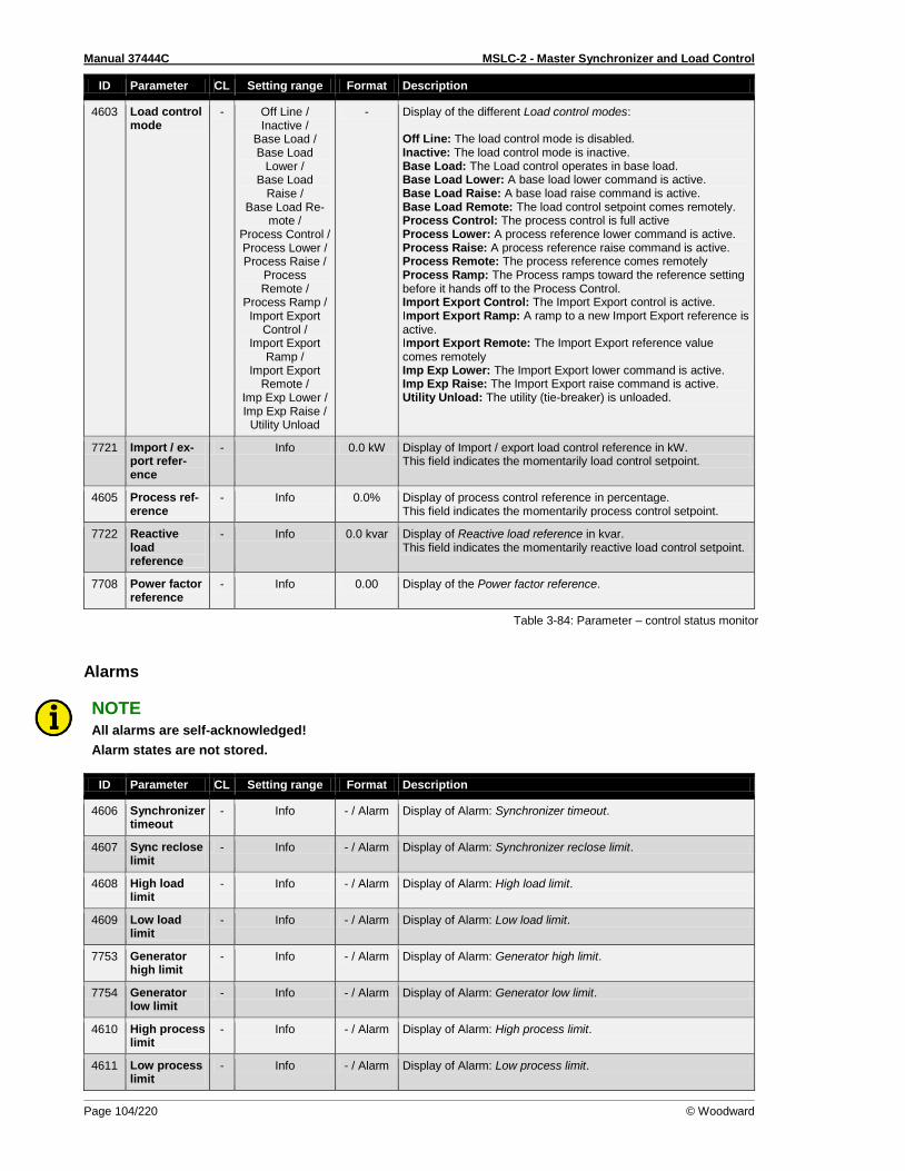
Manual 37444C MSLC-2 - Master Synchronizer and Load Control
Page 104/220 © Woodward
ID Parameter CL Setting range Format Description
4603 Load control mode
- Off Line / Inactive /
Base Load / Base Load
Lower / Base Load
Raise / Base Load Re-
mote / Process Control / Process Lower / Process Raise /
Process Remote /
Process Ramp / Import Export
Control / Import Export
Ramp / Import Export
Remote / Imp Exp Lower / Imp Exp Raise /
Utility Unload
- Display of the different Load control modes: Off Line: The load control mode is disabled. Inactive: The load control mode is inactive. Base Load: The Load control operates in base load. Base Load Lower: A base load lower command is active. Base Load Raise: A base load raise command is active. Base Load Remote: The load control setpoint comes remotely. Process Control: The process control is full active Process Lower: A process reference lower command is active. Process Raise: A process reference raise command is active. Process Remote: The process reference comes remotely Process Ramp: The Process ramps toward the reference setting before it hands off to the Process Control. Import Export Control: The Import Export control is active. Import Export Ramp: A ramp to a new Import Export reference is active. Import Export Remote: The Import Export reference value comes remotely Imp Exp Lower: The Import Export lower command is active. Imp Exp Raise: The Import Export raise command is active. Utility Unload: The utility (tie-breaker) is unloaded.
7721 Import / ex-port refer-ence
- Info 0.0 kW Display of Import / export load control reference in kW. This field indicates the momentarily load control setpoint.
4605 Process ref-erence
- Info 0.0% Display of process control reference in percentage. This field indicates the momentarily process control setpoint.
7722 Reactive load reference
- Info 0.0 kvar Display of Reactive load reference in kvar. This field indicates the momentarily reactive load control setpoint.
7708 Power factor reference
- Info 0.00 Display of the Power factor reference.
Table 3-84: Parameter – control status monitor
Alarms
NOTE All alarms are self-acknowledged!
Alarm states are not stored.
ID Parameter CL Setting range Format Description
4606 Synchronizer timeout
- Info - / Alarm Display of Alarm: Synchronizer timeout.
4607 Sync reclose limit
- Info - / Alarm Display of Alarm: Synchronizer reclose limit.
4608 High load limit
- Info - / Alarm Display of Alarm: High load limit.
4609 Low load limit
- Info - / Alarm Display of Alarm: Low load limit.
7753 Generator high limit
- Info - / Alarm Display of Alarm: Generator high limit.
7754 Generator low limit
- Info - / Alarm Display of Alarm: Generator low limit.
4610 High process limit
- Info - / Alarm Display of Alarm: High process limit.
4611 Low process limit
- Info - / Alarm Display of Alarm: Low process limit.
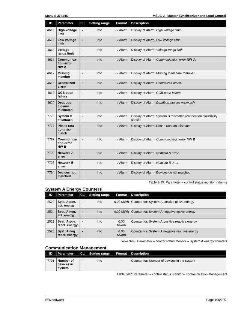
Manual 37444C MSLC-2 - Master Synchronizer and Load Control
© Woodward Page 105/220
ID Parameter CL Setting range Format Description
4613 High voltage limit
- Info - / Alarm Display of Alarm: High voltage limit.
4612 Low voltage limit
- Info - / Alarm Display of Alarm: Low voltage limit.
4614 Voltage range limit
- Info - / Alarm Display of Alarm: Voltage range limit.
4615 Communica-tion error NW A
- Info - / Alarm Display of Alarm: Communication error NW A.
4617 Missing member
- Info - / Alarm Display of Alarm: Missing loadshare member.
4618 Centralized alarm
- Info - / Alarm Display of Alarm: Centralized alarm.
4619 GCB open failure
- Info - / Alarm Display of Alarm: GCB open failure.
4620 Deadbus closure mismatch
- Info - / Alarm Display of Alarm: Deadbus closure mismatch.
7770 System B mismatch
- Info - / Alarm Display of Alarm: System B mismatch (connection plausibility check).
7777 Phase rota-tion mis-match
- Info - / Alarm Display of Alarm: Phase rotation mismatch.
7787 Communica-tion error NW B
- Info - / Alarm Display of Alarm: Communication error NW B
7792 Network A error
Info - / Alarm Display of Alarm: Network A error
7793 Network B error
Info - / Alarm Display of Alarm: Network B error
7794 Devices not matched
Info - / Alarm Display of Alarm: Devices do not matched
Table 3-85: Parameter – control status monitor - alarms
System A Energy Counters
ID Parameter CL Setting range Format Description
2520 Syst. A pos. act. energy
- Info 0.00 MWh Counter for: System A positive active energy
2524 Syst. A neg. act. energy
- Info 0.00 MWh Counter for: System A negative active energy
2522 Syst. A pos. react. energy
- Info 0.00 Mvarh
Counter for: System A positive reactive energy
2526 Syst. A neg. react. energy
- Info 0.00 Mvarh
Counter for: System A negative reactive energy
Table 3-86: Parameter – control status monitor – System A energy counters
Communication Management
ID Parameter CL Setting range Format Description
7791 Number of devices in system
- Info - Counter for: Number of devices in the system
Table 3-87: Parameter – control status monitor – communication management
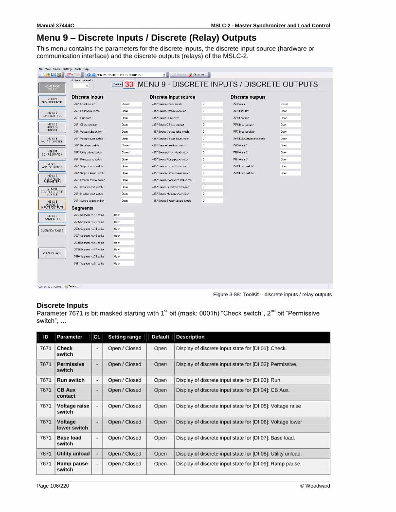
Manual 37444C MSLC-2 - Master Synchronizer and Load Control
Page 106/220 © Woodward
Menu 9 – Discrete Inputs / Discrete (Relay) Outputs This menu contains the parameters for the discrete inputs, the discrete input source (hardware or communication interface) and the discrete outputs (relays) of the MSLC-2.
Figure 3-88: ToolKit – discrete inputs / relay outputs
Discrete Inputs Parameter 7671 is bit masked starting with 1
st bit (mask: 0001h) “Check switch”, 2
nd bit “Permissive
switch”, …
ID Parameter CL Setting range Default Description
7671 Check switch
- Open / Closed Open Display of discrete input state for [DI 01]: Check.
7671 Permissive switch
- Open / Closed Open Display of discrete input state for [DI 02]: Permissive.
7671 Run switch - Open / Closed Open Display of discrete input state for [DI 03]: Run.
7671 CB Aux contact
- Open / Closed Open Display of discrete input state for [DI 04]: CB Aux.
7671 Voltage raise switch
- Open / Closed Open Display of discrete input state for [DI 05]: Voltage raise
7671 Voltage lower switch
- Open / Closed Open Display of discrete input state for [DI 06]: Voltage lower
7671 Base load switch
- Open / Closed Open Display of discrete input state for [DI 07]: Base load.
7671 Utility unload - Open / Closed Open Display of discrete input state for [DI 08]: Utility unload.
7671 Ramp pause switch
- Open / Closed Open Display of discrete input state for [DI 09]: Ramp pause.
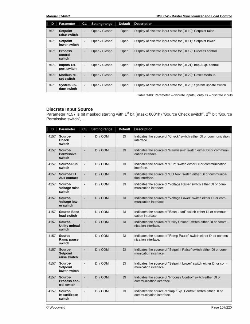
Manual 37444C MSLC-2 - Master Synchronizer and Load Control
© Woodward Page 107/220
ID Parameter CL Setting range Default Description
7671 Setpoint raise switch
- Open / Closed Open Display of discrete input state for [DI 10]: Setpoint raise
7671 Setpoint lower switch
- Open / Closed Open Display of discrete input state for [DI 11]: Setpoint lower
7671 Process control switch
- Open / Closed Open Display of discrete input state for [DI 12]: Process control
7671 Import/ Ex-port switch
- Open / Closed Open Display of discrete input state for [DI 21]: Imp./Exp. control
7671 Modbus re-set switch
- Open / Closed Open Display of discrete input state for [DI 22]: Reset Modbus
7671 System up-date switch
- Open / Closed Open Display of discrete input state for [DI 23]: System update switch
Table 3-89: Parameter – discrete inputs / outputs – discrete inputs
Discrete Input Source Parameter 4157 is bit masked starting with 1
st bit (mask: 0001h) “Source Check switch”, 2
nd bit “Source
Permissive switch”, …
ID Parameter CL Setting range Default Description
4157 Source-Check switch
- DI / COM DI Indicates the source of “Check” switch either DI or communication interface.
4157 Source-Permissive switch
- DI / COM DI Indicates the source of “Permissive” switch either DI or communi-cation interface.
4157 Source-Run switch
- DI / COM DI Indicates the source of “Run” switch either DI or communication interface.
4157 Source-CB Aux contact
- DI / COM DI Indicates the source of “CB Aux” switch either DI or communica-tion interface.
4157 Source-Voltage raise switch
- DI / COM DI Indicates the source of “Voltage Raise” switch either DI or com-munication interface.
4157 Source-Voltage low-er switch
- DI / COM DI Indicates the source of “Voltage Lower” switch either DI or com-munication interface.
4157 Source-Base load switch
- DI / COM DI Indicates the source of “Base Load” switch either DI or communi-cation interface.
4157 Source-Utility unload switch
- DI / COM DI Indicates the source of “Utility Unload” switch either DI or commu-nication interface.
4157 Source Ramp pause switch
- DI / COM DI Indicates the source of “Ramp Pause” switch either DI or commu-nication interface.
4157 Source-Setpoint raise switch
- DI / COM DI Indicates the source of “Setpoint Raise” switch either DI or com-munication interface.
4157 Source-Setpoint lower switch
- DI / COM DI Indicates the source of “Setpoint Lower” switch either DI or com-munication interface.
4157 Source-Process con-trol switch
- DI / COM DI Indicates the source of “Process Control” switch either DI or communication interface.
4157 Source-Import/Export switch
- DI / COM DI Indicates the source of “Imp./Exp. Control” switch either DI or communication interface.
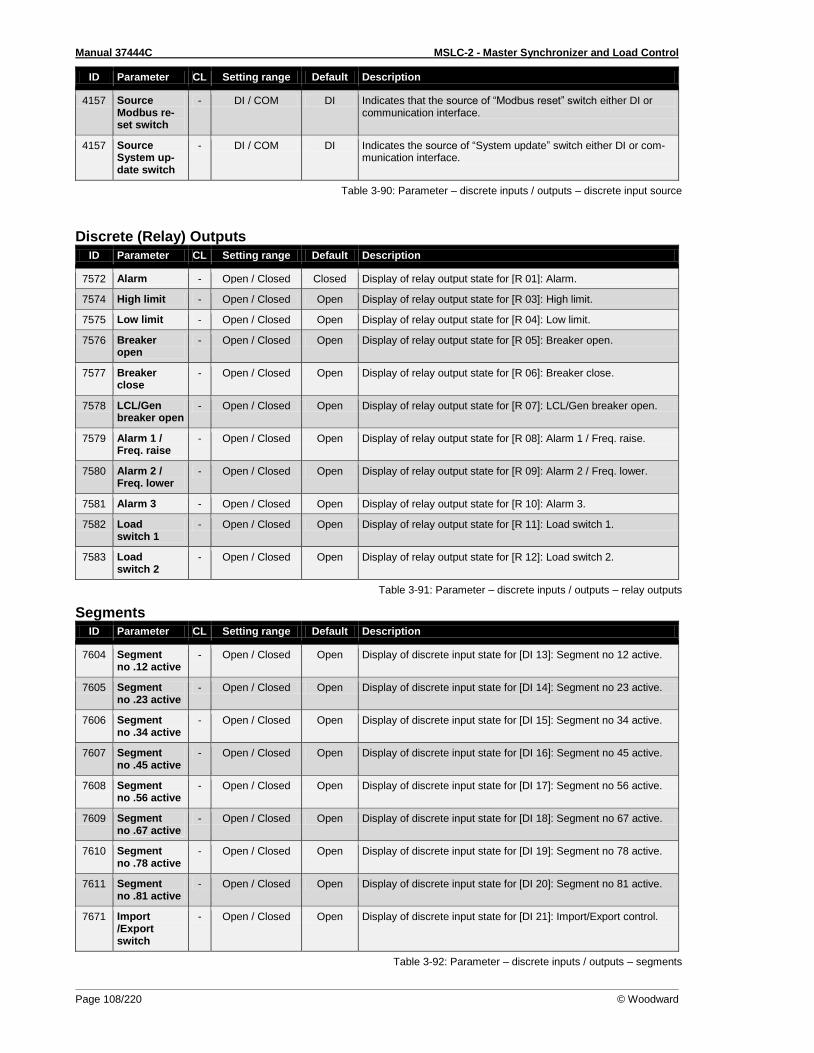
Manual 37444C MSLC-2 - Master Synchronizer and Load Control
Page 108/220 © Woodward
ID Parameter CL Setting range Default Description
4157 Source Modbus re-set switch
- DI / COM DI Indicates that the source of “Modbus reset” switch either DI or communication interface.
4157 Source System up-date switch
- DI / COM DI Indicates the source of “System update” switch either DI or com-munication interface.
Table 3-90: Parameter – discrete inputs / outputs – discrete input source
Discrete (Relay) Outputs
ID Parameter CL Setting range Default Description
7572 Alarm - Open / Closed Closed Display of relay output state for [R 01]: Alarm.
7574 High limit - Open / Closed Open Display of relay output state for [R 03]: High limit.
7575 Low limit - Open / Closed Open Display of relay output state for [R 04]: Low limit.
7576 Breaker open
- Open / Closed Open Display of relay output state for [R 05]: Breaker open.
7577 Breaker close
- Open / Closed Open Display of relay output state for [R 06]: Breaker close.
7578 LCL/Gen breaker open
- Open / Closed Open Display of relay output state for [R 07]: LCL/Gen breaker open.
7579 Alarm 1 / Freq. raise
- Open / Closed Open Display of relay output state for [R 08]: Alarm 1 / Freq. raise.
7580 Alarm 2 / Freq. lower
- Open / Closed Open Display of relay output state for [R 09]: Alarm 2 / Freq. lower.
7581 Alarm 3 - Open / Closed Open Display of relay output state for [R 10]: Alarm 3.
7582 Load switch 1
- Open / Closed Open Display of relay output state for [R 11]: Load switch 1.
7583 Load switch 2
- Open / Closed Open Display of relay output state for [R 12]: Load switch 2.
Table 3-91: Parameter – discrete inputs / outputs – relay outputs
Segments
ID Parameter CL Setting range Default Description
7604 Segment no .12 active
- Open / Closed Open Display of discrete input state for [DI 13]: Segment no 12 active.
7605 Segment no .23 active
- Open / Closed Open Display of discrete input state for [DI 14]: Segment no 23 active.
7606 Segment no .34 active
- Open / Closed Open Display of discrete input state for [DI 15]: Segment no 34 active.
7607 Segment no .45 active
- Open / Closed Open Display of discrete input state for [DI 16]: Segment no 45 active.
7608 Segment no .56 active
- Open / Closed Open Display of discrete input state for [DI 17]: Segment no 56 active.
7609 Segment no .67 active
- Open / Closed Open Display of discrete input state for [DI 18]: Segment no 67 active.
7610 Segment no .78 active
- Open / Closed Open Display of discrete input state for [DI 19]: Segment no 78 active.
7611 Segment no .81 active
- Open / Closed Open Display of discrete input state for [DI 20]: Segment no 81 active.
7671 Import /Export switch
- Open / Closed Open Display of discrete input state for [DI 21]: Import/Export control.
Table 3-92: Parameter – discrete inputs / outputs – segments
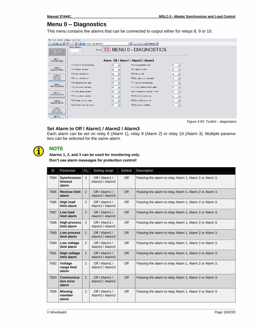
Manual 37444C MSLC-2 - Master Synchronizer and Load Control
© Woodward Page 109/220
Menu 0 – Diagnostics This menu contains the alarms that can be connected to output either for relays 8, 9 or 10.
Figure 3-93: ToolKit – diagnostics
Set Alarm to Off / Alarm1 / Alarm2 / Alarm3 Each alarm can be set on relay 8 (Alarm 1), relay 9 (Alarm 2) or relay 10 (Alarm 3). Multiple parame-ters can be selected for the same alarm.
NOTE Alarms 1, 2, and 3 can be used for monitoring only.
Don’t use alarm messages for protection control!
ID Parameter CL Setting range Default Description
7584 Synchronizer timeout alarm
2 Off / Alarm1 / Alarm2 / Alarm3
Off Passing the alarm to relay Alarm 1, Alarm 2 or Alarm 3.
7585 Reclose limit alarm
2 Off / Alarm1 / Alarm2 / Alarm3
Off Passing the alarm to relay Alarm 1, Alarm 2 or Alarm 3.
7586 High load limit alarm
2 Off / Alarm1 / Alarm2 / Alarm3
Off Passing the alarm to relay Alarm 1, Alarm 2 or Alarm 3.
7587 Low load limit alarm
2 Off / Alarm1 / Alarm2 / Alarm3
Off Passing the alarm to relay Alarm 1, Alarm 2 or Alarm 3.
7588 High process limit alarm
2 Off / Alarm1 / Alarm2 / Alarm3
Off Passing the alarm to relay Alarm 1, Alarm 2 or Alarm 3.
7589 Low process limit alarm
2 Off / Alarm1 / Alarm2 / Alarm3
Off Passing the alarm to relay Alarm 1, Alarm 2 or Alarm 3.
7590 Low voltage limit alarm
2 Off / Alarm1 / Alarm2 / Alarm3
Off Passing the alarm to relay Alarm 1, Alarm 2 or Alarm 3.
7591 High voltage limit alarm
2 Off / Alarm1 / Alarm2 / Alarm3
Off Passing the alarm to relay Alarm 1, Alarm 2 or Alarm 3.
7592 Voltage range limit alarm
2 Off / Alarm1 / Alarm2 / Alarm3
Off Passing the alarm to relay Alarm 1, Alarm 2 or Alarm 3.
7593 Communica-tion error alarm
2 Off / Alarm1 / Alarm2 / Alarm3
Off Passing the alarm to relay Alarm 1, Alarm 2 or Alarm 3.
7595 Missing member alarm
2 Off / Alarm1 / Alarm2 / Alarm3
Off Passing the alarm to relay Alarm 1, Alarm 2 or Alarm 3.
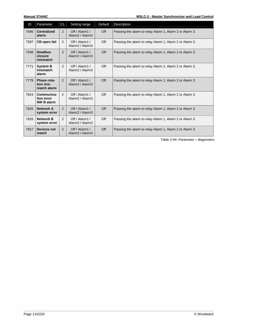
Manual 37444C MSLC-2 - Master Synchronizer and Load Control
Page 110/220 © Woodward
ID Parameter CL Setting range Default Description
7596 Centralized alarm
2 Off / Alarm1 / Alarm2 / Alarm3
Off Passing the alarm to relay Alarm 1, Alarm 2 or Alarm 3.
7597 CB open fail 2 Off / Alarm1 / Alarm2 / Alarm3
Off Passing the alarm to relay Alarm 1, Alarm 2 or Alarm 3.
7598 Deadbus closure mismatch
2 Off / Alarm1 / Alarm2 / Alarm3
Off Passing the alarm to relay Alarm 1, Alarm 2 or Alarm 3.
7771 System B mismatch alarm
2 Off / Alarm1 / Alarm2 / Alarm3
Off Passing the alarm to relay Alarm 1, Alarm 2 or Alarm 3.
7779 Phase rota-tion mis-match alarm
2 Off / Alarm1 / Alarm2 / Alarm3
Off Passing the alarm to relay Alarm 1, Alarm 2 or Alarm 3.
7824 Communica-tion error NW B alarm
2 Off / Alarm1 / Alarm2 / Alarm3
Off Passing the alarm to relay Alarm 1, Alarm 2 or Alarm 3.
7825 Network A system error
2 Off / Alarm1 / Alarm2 / Alarm3
Off Passing the alarm to relay Alarm 1, Alarm 2 or Alarm 3.
7826 Network B system error
2 Off / Alarm1 / Alarm2 / Alarm3
Off Passing the alarm to relay Alarm 1, Alarm 2 or Alarm 3.
7827 Devices not match
2 Off / Alarm1 / Alarm2 / Alarm3
Off Passing the alarm to relay Alarm 1, Alarm 2 or Alarm 3.
Table 3-94: Parameter – diagnostics
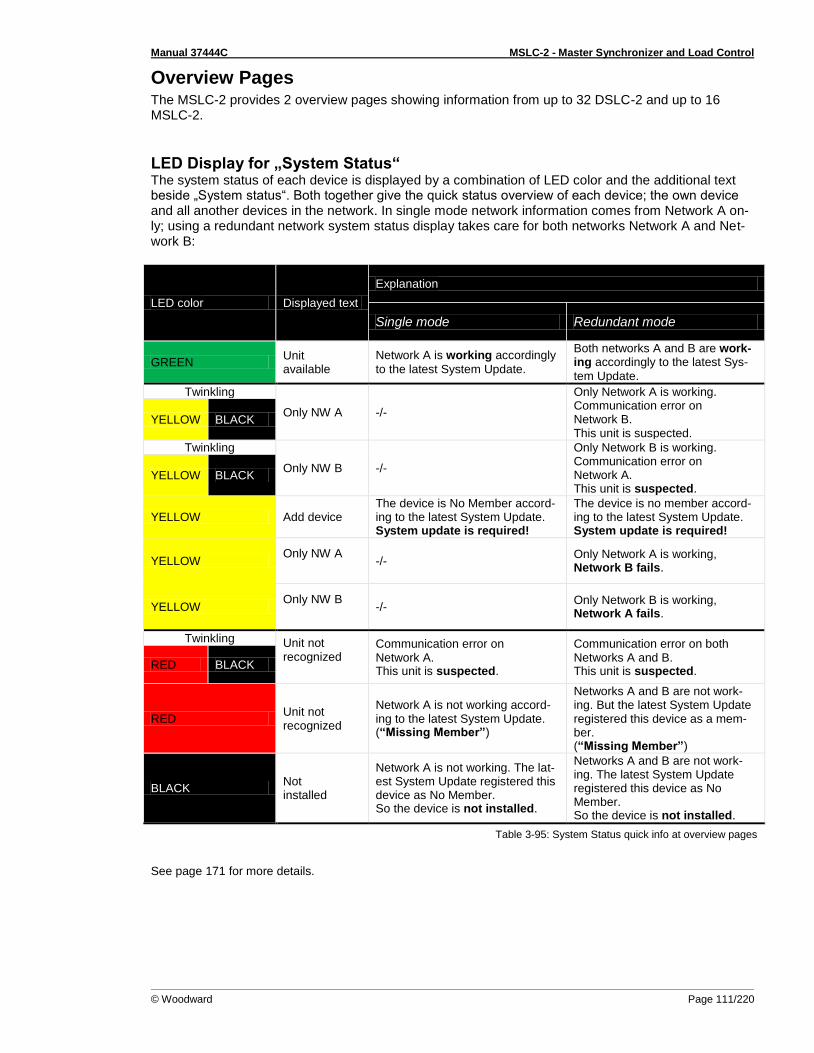
Manual 37444C MSLC-2 - Master Synchronizer and Load Control
© Woodward Page 111/220
Overview Pages The MSLC-2 provides 2 overview pages showing information from up to 32 DSLC-2 and up to 16 MSLC-2.
LED Display for „System Status“ The system status of each device is displayed by a combination of LED color and the additional text beside „System status“. Both together give the quick status overview of each device; the own device and all another devices in the network. In single mode network information comes from Network A on-ly; using a redundant network system status display takes care for both networks Network A and Net-work B:
LED color Displayed text
Explanation
Single mode Redundant mode
GREEN Unit available
Network A is working accordingly
to the latest System Update.
Both networks A and B are work-ing accordingly to the latest Sys-
tem Update.
Twinkling
Only NW A -/-
Only Network A is working. Communication error on Network B. This unit is suspected.
YELLOW BLACK
Twinkling
Only NW B -/-
Only Network B is working. Communication error on Network A. This unit is suspected.
YELLOW BLACK
YELLOW Add device The device is No Member accord-ing to the latest System Update. System update is required!
The device is no member accord-ing to the latest System Update. System update is required!
YELLOW Only NW A
-/-
Only Network A is working, Network B fails.
YELLOW Only NW B
-/-
Only Network B is working, Network A fails.
Twinkling Unit not recognized
Communication error on Network A. This unit is suspected.
Communication error on both Networks A and B. This unit is suspected.
RED BLACK
RED Unit not recognized
Network A is not working accord-ing to the latest System Update. (“Missing Member”)
Networks A and B are not work-ing. But the latest System Update registered this device as a mem-ber. (“Missing Member”)
BLACK Not installed
Network A is not working. The lat-est System Update registered this device as No Member. So the device is not installed.
Networks A and B are not work-ing. The latest System Update registered this device as No Member. So the device is not installed.
Table 3-95: System Status quick info at overview pages
See page 171 for more details.

Manual 37444C MSLC-2 - Master Synchronizer and Load Control
Page 112/220 © Woodward
MSLC-2 Overview Page The MSLC-2 overview informs about the conditions of the MSLC-2 number 33 to 48 connected to the network. This helps for commissioning a DSLC-2 / MSLC-2 system.
Figure 3-96: ToolKit – MSLC-2 overview page
ID Parameter CL Setting range Default Description
Auto segment number
- 1 to 8 - This field indicates what each MSLC-2 recognizes to which seg-ment number it is accorded to.
System status
- Unit available / Add device / Only NW A / Only NW B /
Unit not recog-nized /
Not installed
Not installed
Display if MSLC-2 unit 33 to 48 is available. This text and the illumination of the related LED together describe the device’s status in the system. Refer to page 111 for details.
Table 3-30: Parameter – MSLC-2 overview page
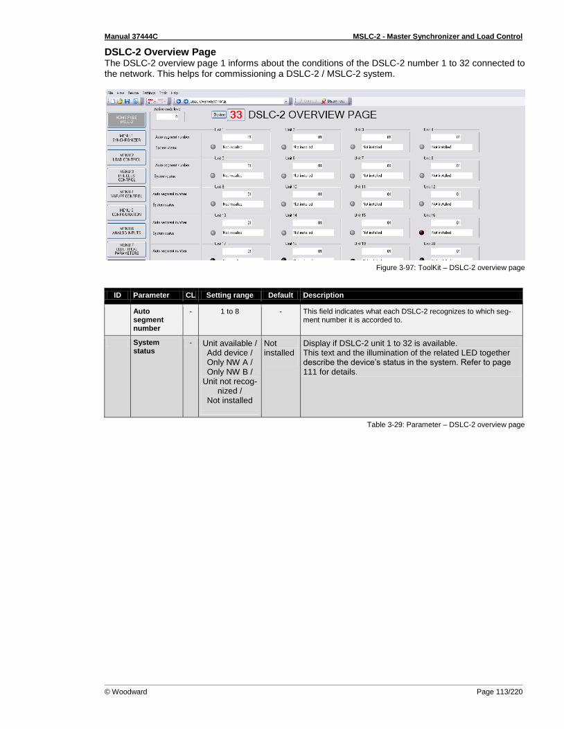
Manual 37444C MSLC-2 - Master Synchronizer and Load Control
© Woodward Page 113/220
DSLC-2 Overview Page The DSLC-2 overview page 1 informs about the conditions of the DSLC-2 number 1 to 32 connected to the network. This helps for commissioning a DSLC-2 / MSLC-2 system.
Figure 3-97: ToolKit – DSLC-2 overview page
ID Parameter CL Setting range Default Description
Auto segment number
- 1 to 8 - This field indicates what each DSLC-2 recognizes to which seg-ment number it is accorded to.
System status
- Unit available / Add device / Only NW A / Only NW B /
Unit not recog-nized /
Not installed
Not installed
Display if DSLC-2 unit 1 to 32 is available. This text and the illumination of the related LED together describe the device’s status in the system. Refer to page 111 for details.
Table 3-29: Parameter – DSLC-2 overview page

Manual 37444C MSLC-2 - Master Synchronizer and Load Control
Page 114/220 © Woodward
Prestart Setup Procedure
≡≡≡≡≡≡≡≡≡≡≡≡≡≡≡≡≡≡≡≡≡≡≡≡≡ Apply power to the MSLC-2 control. Verify that the MSLC-2 control passes its power up diagnostics by checking that self-test relay (terminal 41 / 42) is energized. If the unit fails see Chapter 10.Appendix G Service Options for instructions on getting service for the control. Connect the PC configuration soft-ware ToolKit via RS-232 connection to the MSLC-2.
Configuration Menu Select Menu 5 and adjust all measurement and system relevant configuration items. Set the following setpoints to their appropriate value as described in menu (setpoint) descriptions.
1. Operating Ranges 2. Transformer 3. System Settings
If you have an application with multiple units please check the device number (parameter 1702) of each device:
The DSLC-2s getting device numbers from 1 to 32
The MSLC-2s getting device numbers from 33 to 48

Manual 37444C MSLC-2 - Master Synchronizer and Load Control
© Woodward Page 115/220
Prestart Segmenting Setup The Menu 5 contains a configuration named Basic Segment Number (parameter 4544). In the following cases the basic segment number is configured to the default value (1):
There is only one single DSLC-2 in use
There are several DSLC-2 / MSLC-2 installed, which work on a common bus, which cannot be separated. (only one segment available)
When the application contains switching elements between DSLC-2s and/or MSLC-2s proceed with following rules:
1. Draw an online diagram of your application with all generators, breakers and utility inputs. Then arrange the DSLC-2 (and MSLC-2) at the according breaker. Refer to Figure 3-98.
Figure 3-98: Example of an online diagram – step 1
2. Draw the measurement systems arrows between unit and bars (refer to Figure 3-99).
Please consider following rules:
The DSLC-2 is placed at the generator breaker.
The MSLC-2 can be placed at the tie-breaker and at the utility breaker.
The MSLC-2 at the utility is doing the utility voltage measurement with System A measurement always. The system B/Busbar measurement is connected to the busbar (no Aux. measurement in this sample).
The MSLC-2 at the tie-breaker usually has the system A on the left side and the system B on the right side.

Manual 37444C MSLC-2 - Master Synchronizer and Load Control
Page 116/220 © Woodward
3. Draw the segment numbers into your online diagram (refer to Figure 3-99). Please consider following rules:
Begin on the left side with segment number 1.
The utility and the generators are not segments in sense of the DSLC-2 / MSLC-2 system.
The segment numbers have to follow a line and shall not branch. (Please refer there for to the chapter Network/System) for a better understanding.
4. Draw the device numbers of your units in your online diagram (refer to Figure 3-99). Please consider following rules (for a better overview and understanding):
The DSLC-2 on the left side should begin with device number 1.
The DSLC-2s getting device numbers between 1 and 32.
The MSLC-2 on the left side should begin with device number 33.
The MSLC-2s getting device numbers between 33 and 48. 5. Draw the “CB Aux” feedbacks and segment connection feedbacks in your online diagram
(refer to Figure 3-99). Please consider following rules (for a better overview and understanding):
The DSLC-2 getting usually only their generator breaker feedback.
The MSLC-2 at the utility breaker getting usually only their utility breaker feedback.
The MSLC-2 at the tie-breaker getting usually their tie-breaker feedback and parallel the ac-cording segment connector feedback.
Figure 3-99: Example of an online diagram with segment numbers and segment connector feedbacks
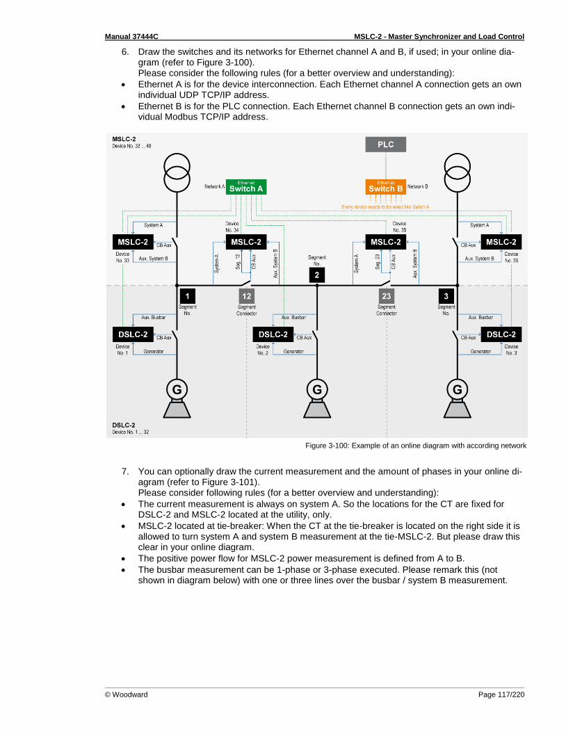
Manual 37444C MSLC-2 - Master Synchronizer and Load Control
© Woodward Page 117/220
6. Draw the switches and its networks for Ethernet channel A and B, if used; in your online dia-gram (refer to Figure 3-100). Please consider the following rules (for a better overview and understanding):
Ethernet A is for the device interconnection. Each Ethernet channel A connection gets an own individual UDP TCP/IP address.
Ethernet B is for the PLC connection. Each Ethernet channel B connection gets an own indi-vidual Modbus TCP/IP address.
Figure 3-100: Example of an online diagram with according network
7. You can optionally draw the current measurement and the amount of phases in your online di-
agram (refer to Figure 3-101). Please consider following rules (for a better overview and understanding):
The current measurement is always on system A. So the locations for the CT are fixed for DSLC-2 and MSLC-2 located at the utility, only.
MSLC-2 located at tie-breaker: When the CT at the tie-breaker is located on the right side it is allowed to turn system A and system B measurement at the tie-MSLC-2. But please draw this clear in your online diagram.
The positive power flow for MSLC-2 power measurement is defined from A to B.
The busbar measurement can be 1-phase or 3-phase executed. Please remark this (not shown in diagram below) with one or three lines over the busbar / system B measurement.
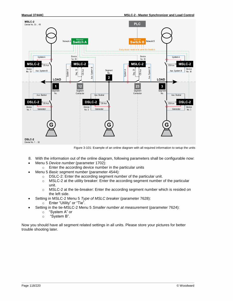
Manual 37444C MSLC-2 - Master Synchronizer and Load Control
Page 118/220 © Woodward
Figure 3-101: Example of an online diagram with all required information to setup the units
8. With the information out of the online diagram, following parameters shall be configurable now:
Menu 5 Device number (parameter 1702): o Enter the according device number in the particular units
Menu 5 Basic segment number (parameter 4544): o DSLC-2: Enter the according segment number of the particular unit. o MSLC-2 at the utility breaker: Enter the according segment number of the particular
unit. o MSLC-2 at the tie-breaker: Enter the according segment number which is resided on
the left side.
Setting in MSLC-2 Menu 5 Type of MSLC breaker (parameter 7628): o Enter “Utility” or “Tie”.
Setting in the tie-MSLC-2 Menu 5 Smaller number at measurement (parameter 7624): o “System A” or o “System B”.
Now you should have all segment related settings in all units. Please store your pictures for better trouble shooting later.
Manual 37444C MSLC-2 - Master Synchronizer and Load Control
© Woodward Page 119/220
Prestart Synchronizer Setup Set all synchronizer (Menu 1) setpoints according to the descriptions above and the work sheet. Leave unknown values, such as gain and stability, at their default values.
Prestart Load Control Setup Set all load control (Menu 2) setpoints according to the descriptions above and the work sheet. Propor-tional load control mode should be used during initial setup of the DSLC-2 control. Set the unload trip setpoint to approximately 10% of rated load.
Prestart Process Control Setup Set all process control (Menu 3) setpoints according to the descriptions above and the work sheet. If gain and stability values (process control integral gain / … derivative ratio) are unknown, leave at their default values.
Prestart Var/Power Factor Control Setup Set all var/power factor control (Menu 4) setpoints according to the descriptions above and the work sheet. Set VAR PF control mode (parameter 7558) to “Disabled” until doing the var/PF control adjust-ment section on page 129ff.
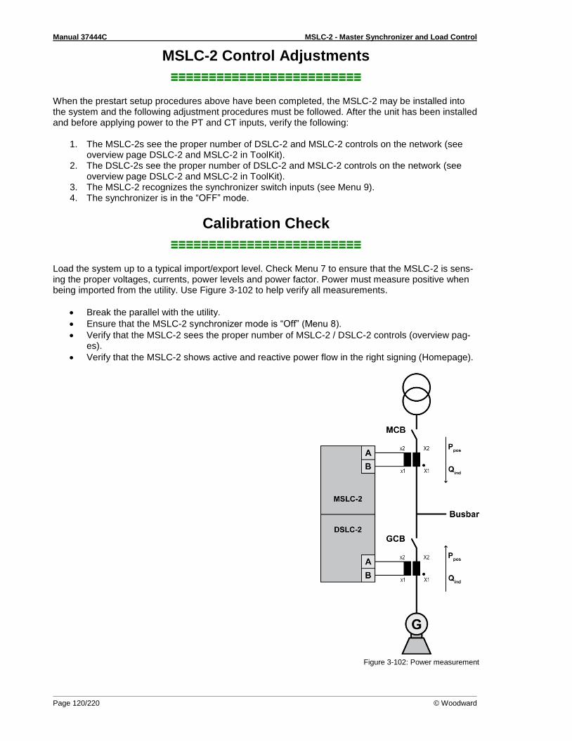
Manual 37444C MSLC-2 - Master Synchronizer and Load Control
Page 120/220 © Woodward
MSLC-2 Control Adjustments
≡≡≡≡≡≡≡≡≡≡≡≡≡≡≡≡≡≡≡≡≡≡≡≡≡ When the prestart setup procedures above have been completed, the MSLC-2 may be installed into the system and the following adjustment procedures must be followed. After the unit has been installed and before applying power to the PT and CT inputs, verify the following:
1. The MSLC-2s see the proper number of DSLC-2 and MSLC-2 controls on the network (see overview page DSLC-2 and MSLC-2 in ToolKit).
2. The DSLC-2s see the proper number of DSLC-2 and MSLC-2 controls on the network (see overview page DSLC-2 and MSLC-2 in ToolKit).
3. The MSLC-2 recognizes the synchronizer switch inputs (see Menu 9). 4. The synchronizer is in the “OFF” mode.
Calibration Check
≡≡≡≡≡≡≡≡≡≡≡≡≡≡≡≡≡≡≡≡≡≡≡≡≡ Load the system up to a typical import/export level. Check Menu 7 to ensure that the MSLC-2 is sens-ing the proper voltages, currents, power levels and power factor. Power must measure positive when being imported from the utility. Use Figure 3-102 to help verify all measurements.
Break the parallel with the utility.
Ensure that the MSLC-2 synchronizer mode is “Off” (Menu 8).
Verify that the MSLC-2 sees the proper number of MSLC-2 / DSLC-2 controls (overview pag-es).
Verify that the MSLC-2 shows active and reactive power flow in the right signing (Homepage).
Figure 3-102: Power measurement
Manual 37444C MSLC-2 - Master Synchronizer and Load Control
© Woodward Page 121/220
Synchronizer Adjustments
≡≡≡≡≡≡≡≡≡≡≡≡≡≡≡≡≡≡≡≡≡≡≡≡≡ This section is for adjusting the synchronizer functions including procedures for phase matching and slip frequency synchronization. Note that dynamic adjustments for gain and stability will be different for each method. To assist in setup and adjustments, you can monitor synchronizer mode of operation on Homepage or Menu 8 and synchronizer mode and slip frequency and synchronoscope values on Menu 7.
Preliminary Synchronizer Adjustments 1. Set the Voltage matching setpoint (parameter 7513) to “Disabled”. 2. Select Menu 1 and verify that the Frequency synchronizer proportional gain (parameter 4539)
and Frequency synchronizer integral gain (parameter 4540) setpoints are set to their default values.
3. Set the maximum phase window (parameter 5703, parameter 5704) and maximum slip window (parameter 5701, parameter 5702) setpoints to the desired values or use the default values if unknown.
4. Set the ramp rate for the Digital Input Frequency setpoint raise and lower ( parameter 4713, parameter 4714)
5. Set Breaker delay (parameter 5705) to the closure time specified by the breaker manufacturer. Add delay time for any interposing relays if required.
6. Set CB close hold time (parameter 3417) to the time desired for the MSLC-2 control to hold the breaker closure signal. This time should at least exceed the breaker delay time.
7. Set the close attempts (parameter 3419) setpoint to “1”. 8. Set the Synchronizer timeout (parameter 3063) setpoint to “0”. 9. Set Auto re-synchronize (parameter 7514) to “Disabled”.
Proceed to the phase matching synchronizer or slip frequency synchronizer section as required.
Phase Matching Synchronizer Do the following steps to setup the synchronizer dynamics for use as a phase matching synchronizer. For slip frequency synchronizing, see the procedure below. The MSLC-2 control indicates the phase angle with the Synchronoscope on the ToolKit Homepage (parameter 4639).
NOTE The synchronoscope on the Homepage will show the right phase angle, when all electrical settings are correctly done and the wire connections to the unit are correct. Double check the phase angle across the breaker with a voltmeter or other phase testing device.
1. Set the Synchronization CB (parameter 5730) to “Phase matching”. 2. Close the synchronizer “Check” mode switch. 3. With System A active (mainly utility) system B active (mainly generator bus), adjust the syn-
chronizer proportional gain setpoint for stable control of the utility frequency as indicated by synchronoscope holding steady at zero phase.
NOTE If the system (not the MSLC-2 control) synchronoscope does not lock close to zero phase, but at some other value (such as 30, 60, 180, 210, etc. degrees), verify system A and system B potential wiring to ei-ther the synchronoscope or MSLC-2 control.
DO NOT PROCEED WITH ANY ACTION RESULTING IN BREAKER CLOSURE UNTIL THE PROBLEM IS DETERMINED AND CORRECTED.
4. Turn the synchronizer mode to “Off” (open discrete inputs). Allow the phase to drift until the
synchronoscope indicates approximately 150 degrees fast. It may be necessary to adjust the engine speed setting slightly fast to achieve the desired phase drift.
5. Turn the synchronizer mode to “Check”. The synchronizer should pull the generator smoothly into phase lock. If the synchronizer action is too slow, increase Frequency synchronizer pro-
Manual 37444C MSLC-2 - Master Synchronizer and Load Control
Page 122/220 © Woodward
portional gain (parameter 4539) by a factor of two. If increasing sync gain results in unstable operation, reduce the value by at least one-half and proceed to step 6. Otherwise, repeat steps 4 and 5.
6. Do step 4 and then turn the synchronizer mode to “Check”. The synchronizer should pull the generator smoothly into phase lock. If the synchronizer is too slow or “over-damped”, increase integral gain (parameter 4540) by a factor of two to decrease damping and increase sync proportional gain by a factor of two. If the synchronizer is too fast or “under-damped” as indicated by excessive overshoot of zero phase when pulling in, decrease sync proportional gain by a factor of two and decrease integral gain by a factor of two to increase damping.
7. Repeat steps 4, 5 and 6, with smaller adjustment steps until satisfactory performance is ob-tained.
8. Turn the synchronizer mode to “Off”. Allow the phase to drift until the synchronoscope indi-cates approximately 150 degrees slow. It may be necessary to adjust the engine speed setting slightly slow to achieve the phase drift. Repeat steps 5 and 6 if necessary to get the desired performance.
9. Verify synchronizer performance under all expected operating conditions, such as synchroniz-ing at higher or lower speeds.
10. If voltage matching is to be used, do the setup in the voltage matching section below.
Proceed to final synchronizer setup.
Slip Frequency Synchronizer Do the following steps to setup the synchronizer dynamics for use as a slip frequency synchronizer.
1. Complete the phase matching synchronizer setup before continuing. 2. Turn the synchronizer mode to “Off”. Set the Slip frequency setpoint offset (parameter 4712) to
the desired slip rate. Set engine speed slightly slow. 3. Turn the synchronizer mode to “Check”. The synchronizer should drive engine speed so that
phase rotation is smooth and at the correct rate as indicated on a synchronoscope or by ob-serving the slip frequency value on Menu 7 (parameter 4640). If the synchronizer is too slow to react when switched from off to check mode, increase Frequency synchronizer proportional gain (parameter 4539) by a factor of two. If the synchronizer action is too aggressive when switched to check mode, reduce the sync proportional gain by half of what your last adjust-ment. Example: If you moved from a proportional gain of 1 to 2, reduce to 1.5. Repeat until the synchronizer controls the system A at your desired rate.
4. Observe the smoothness of phase rotation. If a slow hunt is observed, as indicated by slowing and speeding up of the synchronoscope during rotation, increase Frequency synchronizer in-tegral gain (parameter 4540) by a factor of two and repeat step 3. If rapid changes in slip fre-quency occur, decrease sync integral gain.
5. Repeat steps 3 and 4 with smaller adjustment steps until satisfactory performance is obtained. Note that it may not be possible to remove all slow hunting in slip frequency and this will not adversely affect synchronization.
6. Verify synchronizer performance under all expected operating conditions, such as synchroniz-ing from higher or lower speeds.
7. If voltage matching or the var/PF control is to be used, do the setup in the voltage matching adjustment section below.
Proceed with final synchronizer setup.

Manual 37444C MSLC-2 - Master Synchronizer and Load Control
© Woodward Page 123/220
Final Synchronizer Setup 1. Open the circuit breaker to disconnect the system A (usually mains) from system B. 2. Set close attempts (parameter 3419) to the desired number of times the synchronizer should
attempt to close the circuit breaker. Set to “1” if only one close attempt should be made. 3. Set Reclose delay (parameter 4534) to the desired interval between close attempts. This
should be greater than the time required to recharge the circuit breaker arming mechanism. 4. If an alarm is desired when the maximum close attempts has been reached, set sync reclose
alarm to “Enabled”. 5. Set the Synchronizer timeout (parameter 3063) to the maximum number of seconds the synchro-
nizer should attempt to achieve synchronization. Set to “0” for no timeout. 6. If an alarm is desired when the sync timeout interval expires, set the Synchronizer timeout
alarm (parameter 7557) setpoint to “Enabled”.
7. If it is desired to automatically attempt to reclose the circuit breaker on loss of synchronization (CB Aux opens after a successful closure has been accomplished), set the Auto re-synchronize (parameter 7514) setpoint to “Enabled”. If set to “Disabled”, the synchronizer will enter an auto-off mode when synchronization is obtained. It will be necessary to set the syn-chronizer mode switch to “Off” and back to the desired operating mode to restart the synchro-nizer.
This completes the MSLC-2 control synchronizer setup.
Manual 37444C MSLC-2 - Master Synchronizer and Load Control
Page 124/220 © Woodward
Voltage Matching Adjustments
≡≡≡≡≡≡≡≡≡≡≡≡≡≡≡≡≡≡≡≡≡≡≡≡≡ The following steps will verify the correct operation of the synchronizer voltage matching function. With the breaker open and at least one generator on line, momentarily raise and lower the voltage on the lo-cal generator bus.
NOTE Individual DSLC-2 controls must be setup for proper voltage regulator control prior to adjusting the MSLC-2 control (See the DSLC-2 manual).
Preliminary Voltage Matching Setup 1. Select Menu 1 and set the Voltage matching (parameter 7513) setpoint to “Enabled”. 2. Select Menu 7 and display both system A and system B voltages. 3. With the synchronizer “Off”, manually raise the local bus (system B) voltage until it is approxi-
mately 5% higher than the utility voltage. 4. Set the synchronizer mode to “Check”. The MSLC-2 should adjust the local bus voltage until it
is within the voltage window selected in Menu 1. 5. If the voltage cycles through the window without settling into it, use the Voltage synchronizer
proportional gain (parameter 5610) and integral gain to obtain the response you want. Lower-ing these values will slow the response. It might be that the DSLC-2s will have to be adjusted to obtain the response needed.
6. Set the synchronizer to “Off”, manually lower the local bus voltage until it is approximately 5%
lower than the utility voltage. 7. Set the synchronizer mode to “Check”. The MSLC-2 should adjust the local bus voltage until it
is within the voltage window selected in Menu 1.
NOTE If the slip frequency reference is set to zero, the voltage window is ± the setpoint chosen in Menu 1. If the slip frequency reference is set to a negative or slow slip, the voltage window is such that the local bus voltage must be less than the utility voltage. Conversely, if the slip frequency reference is set to a positive or fast slip, the voltage window is such that the local bus voltage must be greater than the util-ity voltage. This ensures that the initial flow of reactive power is in the same direction as the initial flow of real power.
Final Voltage Matching Setup 1. Set the voltage high/low limits in Menu 3 to their desired values. 2. Enable the voltage alarms and voltage switches in Menu 3 if it is desired to activate the alarm
or the high/low limit relay drivers upon exceeding a setpoint.
Manual 37444C MSLC-2 - Master Synchronizer and Load Control
© Woodward Page 125/220
Load Control Adjustment
≡≡≡≡≡≡≡≡≡≡≡≡≡≡≡≡≡≡≡≡≡≡≡≡≡ This section contains the instructions for setup of the MSLC-2 load control. Set all load control setpoints (Menu 2) according to the descriptions above and the work sheet. The Homepage or Menu 8 displays the load control mode, import/export reference and load command outputs are provided to as-sist in setup and verification of correct operation.
Base Load Mode Setup The base load mode is used when manual control of the operating generators is required, or whenever the generators are desired to be maintained at a set percentage of their rated load without regard to plant loading or import/export levels.
1. Adjust the setpoints in Menu 2 as described above. Set the parameter Load control setpoint source (parameter 7634) to “Internal”. Check that the DIs setpoint raise and lower are not energized.
2. Switch the MSLC-2 in base load master control. This is done by energizing the DI “Base Load” and the “CB Aux”.
3. Break the parallel between the local bus (system A) and the utility (system B). Place at least one generator in isochronous load sharing (isolated run).
4. Watch the Load control mode field (parameter 4603) in the Homepage. Re-synchronize and parallel the local bus (system B) to the utility (system A). Verify that, when the breaker at the MSLC-2 closes, the load command assumes the value of system load immediately prior to paralleling.
5. Temporarily issue a lower setpoint command and then a raise setpoint command. Verify that the load command changes appropriately and that the engines running in base load respond appropriately. You can watch in the Homepage the setpoint load level going down to the DSLC-2s (parameter 4629).
Remote Base Load Do the following steps if the analog Remote load reference input (parameter 7738) is used in base load control.
1. As a basic do the base load mode setup described above. 2. The value of the remote input is to configure and can be viewed in Menu 6. Before you start
the engine check over the displaying field in Menu 6 (parameter 7738) if the analog input is right transformed in a base load reference value in kW.
3. Switch the MSLC-2 in base load master control. This is done by energizing the DI “Base Load”. 4. Synchronize and parallel the local bus (system B) to the utility (system A) in the base load
mode. Adjust the signal input to a level different from the present base load level. 5. Close both the raise and lower setpoint contacts to select the remote mode. The Load control
mode (parameter 4603) in Menu 8 or in the Homepage should indicate base load and the load command should ramp to the specified level.
6. Raise and lower the analog signal. The load will ramp at the rates chosen in Menu 2 load and unload ramp rates. These rates may be adjusted to achieve satisfactory performance.
7. Open the raise and lower setpoint contacts. The Load control mode (parameter 4603) should indicate base load and the control remains at the last base load level chosen by the analog in-put.
This completes the remote base load reference setup procedure.

Manual 37444C MSLC-2 - Master Synchronizer and Load Control
Page 126/220 © Woodward
Import/Export Mode Setup 1. As a basic do the base load mode setup described above. 2. An important assumption for setup this mode is the right connection of the CT´s of the MSLC-
2. Be sure that incoming real power (power flow from system A to system B) is displayed posi-tive (see Homepage) and incoming lagging reactive power is displayed positive as well. Do not proceed if you have not clarified the right measurement.
3. Check Menu 2 setpoints for Import/export control proportional gain (parameter 5510), Im-port/export control integral gain (parameter 5511), and Import/export control derivative ratio (parameter 5512) whether they are adjusted to their default values.
4. Adjust the setpoints in Menu 2 as described in the parameter setup chapter above. Set the pa-rameter Load control setpoint source (parameter 7634) to “Internal”. Check that the DI´s setpoint raise and lower are not energized. Configure an import/export reference (parameter 7717), positive value is importing power from mains, negative value is exporting power to mains.
NOTE
Do not chose an export level if it is not allowed by the utility.
5. Switch the MSLC-2 in import/export load master control. This is done by energizing the DI “Im-port/Export Control”.
6. Break the parallel between the local bus (system A) and the utility (system B). Place at least one generator in isochronous load sharing.
7. Re-synchronize and parallel the local bus (system B) to the utility (system A). Verify that, when the breaker at the MSLC-2 closes, the load command assumes the value of system load im-mediately prior to paralleling. The control will ramp the Setpoint load level (parameter 4629) output until the import/export level is within its target.
8. If the import/export control is unstable when taking control, decrease the import/export propor-tional gain to achieve stability. If the chosen import/export level is not obtainable within the 0 to 100% load command range, the control will stop at 0% or 100%. If a slow hunt is observed or excessive overshoot of the export/import value occurs, decrease the process integral gain.
9. Temporarily issue a lower setpoint command and then a raise setpoint command. Verify that the import/export reference changes appropriately and that the running engines respond ap-propriately. You can watch in the Homepage the Setpoint load level (parameter 4629) decreas-ing to the DSLC-2s.
This completes the import/export setup.
Remote Import/Export Setup Do the following steps if analog remote load reference input is to be used. The value of the remote in-put is configured and viewed in Menu 6.
1. As a basic do the import/export load mode setup described above. 2. Set the scaling of the analog signal according to the instructions of the Menu 6. The remote
load reference signal will be interpreted as an import/export load reference when the DI im-port/export control is given.
3. Close both the raise and lower setpoint contacts to select the remote mode. The load control mode in Menu 8 or the Homepage should indicate import/export remote and the load com-mand of the MSLC-2 to DSLC-2 ramps to the needed level.
4. Raise and lower the analog signal. The load will ramp at the rates chosen in Menu 2 load and unload ramp rates. These rates may be adjusted to achieve satisfactory performance. Open the raise and lower setpoint contacts the load control mode indicates import/export control and the control keeps the last import/export level.
This completes the remote import/export reference setup procedure.
Manual 37444C MSLC-2 - Master Synchronizer and Load Control
© Woodward Page 127/220
Final Load Control Setup 1. Set Menu 2 Load ramp rate (parameter 4700) and Unload ramp rate (parameter 4524) to de-
sired values. 2. Set Raise load rate (parameter 4515) and Lower load rate (parameter 4516) to desired values. 3. Set the Utility unload trip (parameter 4506) and Generator unload trip (parameter 3125) levels
to their desired values. 4. The import real load can be monitored by the high load Limit PU (pick up) and DO (drop out)
setpoints. The settings are related on a rated power System A (parameter 1752). 5. The export real load can be monitored by the low load limit PU (pick up) and DO (drop out)
setpoints. The settings are related on a rated power at the interchange point (parameter 1752). 6. If it is desired that the alarm output High load limit (parameter 4608) alarm is activated when
load reaches the high limit PU, set the high load limit alarm setpoint to “Enabled”. The alarm will be automatically cleared when load drops below the high load limit DO switch point.
7. If it is desired that the alarm output Low load limit (parameter 4609) alarm is activated when load reaches the low limit PU, set the low load limit alarm setpoint to “Enabled”. The alarm will be automatically cleared when load increases to above the low load limit DO switch point.
8. If it is desired that the high and low limit switches also activate the “High Limit” and “Low Limit” relays, set the Load limit switch (parameter 7506) setpoint to “Enabled”.
9. Set the load switch PU and load switch DO setpoints to their desired operating levels.
Manual 37444C MSLC-2 - Master Synchronizer and Load Control
Page 128/220 © Woodward
Process Control Adjustment
≡≡≡≡≡≡≡≡≡≡≡≡≡≡≡≡≡≡≡≡≡≡≡≡≡ This section contains instructions for setup of the MSLC-2 process control. Menu 6 provides the setting for the process input signal and the according engineering units. Menu 6 and the Homepage displays the resulting real signal in percentage and in engineering units. Menu 8 shows the process control setpoint in percentage. The Homepage displays the setpoint process control in percentage and engi-neering units.
1. Configure in Menu 6 the Process signal input (parameter 7727) according to the chapter setup description Menu 6 in this manual. Don’t forget to scale engineering units according to the real process signal. This is the base that the process control reference signal can be interpreted.
2. Check Menu 3 setpoints for Process control proportional gain (parameter 4500), Process con-trol integral gain (parameter 4501), Process control derivative ratio (parameter 4502) and Pro-cess filter (parameter 4509) whether they are adjusted to their default values.
3. Set Menu 3 Process control action (parameter 7559) to “Direct” or “Indirect” as required for the process. If increasing load also increases the process input signal level, use “Direct”. If in-creasing load decreases the process input signal level, use “Indirect”.
4. Set the internal Process reference (parameter 7737) setpoint Menu 3 to a value requiring ap-proximately 50% load to maintain the process signal level. If the required process reference is not known at start-up, operate the MSLC-2 in base load mode. Use the raise and lower setpoint inputs to adjust the load until the desired process level is obtained. Observe the pro-cess input in Menu 6 or the Homepage to determine the required process reference value.
5. Close the process switch. Select “Run” on the MSLC-2 to parallel the local bus with the utility. The MSLC-2 will ramp into process control.
6. If the process control is unstable when taking control, decrease the Process control propor-tional gain to achieve stability. If decreasing Process control proportional gain (parameter 4500) increases instability, increase Process control integral gain (parameter 4501). If the pro-cess control gain is too slow, increase the Process control proportional gain (parameter 4500) by a factor of two. If a slow hunt is observed or excessive overshoot of the process reference settings occurs, increase the process integral gain by a factor of two.
7. In systems experiencing rapid fluctuations of the process input, increasing the process filter will provide a slower but more stable response.
8. Introduce Process droop (parameter 4508) if required. 9. The real process value can be monitored by the Process high limit PU (parameter 4510) and
DO setpoints to issue an alarm. 10. The real process value can be monitored by the Process low limit PU (parameter 4513) and
DO setpoints to issue an alarm. 11. If it is desired that the alarm output High process limit (parameter 4610) alarm is set when the
process input reaches the Process high limit PU (parameter 4510), set the Process high limit alarm (parameter 7500) setpoint to “Enabled”. The alarm will be automatically cleared when the process input level drops below the Process high limit DO (parameter 4511) switch point.
12. If it is desired that the alarm output Low process limit alarm (parameter 7589) is set when the process input reaches the Process low limit PU (parameter 4513), set the Process low limit alarm (parameter 7501) setpoint to “Enabled”. The alarm will be automatically cleared when the process input increases to a level above the Process low limit DO (parameter 4514) switch point.
13. If it is desired that the high and low limit switches also activate the “High Limit” and “Low Limit” relays, set the Process switches (parameter 7502) setpoint to “Enabled”.
This completes setup and adjustment of the MSLC-2 process control function.
Manual 37444C MSLC-2 - Master Synchronizer and Load Control
© Woodward Page 129/220
Var/PF Control Adjustment
≡≡≡≡≡≡≡≡≡≡≡≡≡≡≡≡≡≡≡≡≡≡≡≡≡ This section describes the setup and adjustment of the MSLC-2 voltage/var/PF control functions. The voltage control is used in case of voltage matching for the synchronizer. The var/PF control is used, if the DSLC- 2 / MSLC-2 system runs parallel to the utility. The values of kvars and average power factor are available in Menu 7 or the Homepage.
NOTE Var/PF control effectiveness depends on var/PF control in the DSLC-2s. Because of that commission the DSLC-2 var/PF control first.
1. Verify that the voltage matching adjustments above have been done. 2. Select Menu 4 and set VAR control proportional gain (parameter 5613), VAR control integral
gain (parameter 5614) and VAR control derivative ratio (parameter 5615) to their default val-ues.
Constant Generator Power Factor Setup The MSLC-2 can send a constant generator power factor setpoint to the DSLC-2s. The power factor reference is configured in Menu 4 (parameter 5621). The constant generator power factor will be exe-cuted, if:
The MSLC-2 runs in base load mode OR o When in Base load mode, the MSLC-2 can only operate in the constant generator PF
mode.
The MSLC-2 runs in export/import mode and the VAR PF control mode (parameter 7558) in Menu 4 is configured to “Constant Generator PF”.
1. Set the VAR control setpoint source (parameter 7635) to “Internal”. Set the desired constant
generator power factor reference in Menu 4 (parameter 5621). 2. Run the DSLC-2 / MSLC-2 system parallel to the utility. For test purposes change between dif-
ferent constant generator power factors to validate the functionality. When the power factor at the DSLC-2 begins to swing check the settings at the DSLC-2s.
This completes setup of the MSLC-2 constant generator power factor function.
Manual 37444C MSLC-2 - Master Synchronizer and Load Control
Page 130/220 © Woodward
PF Control at the Utility - Setup The MSLC-2 can regulate a power factor at the interchange point. A PID control compares the power factor reference with the real value and sends a reactive load setpoint to the DSLC-2 to run the error signal to zero. Whatever is sent for reactive load level to the DSLC-2s, the DSLC-2 allows not more than 10% rated vars for leading and do not allow more than 100% rated vars for lagging.
1. Set the VAR control setpoint source (parameter 7635) to “Internal”. Set the VAR PF control mode (parameter 7558) to “PF Control”. Set the desired Power factor reference (parameter 5620) in Menu 4.
2. An important assumption for setup is the right connection of the CTs of the MSLC-2. Be sure that incoming power is displayed positive (refer to ToolKit Homepage) and incoming lagging reactive power is displayed positive as well. Do not proceed if you have not clarified the right measurement.
3. Check Menu 4 setpoints for VAR control proportional gain (parameter 5613), VAR control inte-gral gain (parameter 5614), and VAR control derivative ratio (parameter 5615) whether they are adjusted to their default values.
4. Switch to base load at the MSLC-2. 5. Run the DSLC-2 / MSLC-2 system parallel to the utility. For test purposes change between dif-
ferent setpoints for the constant generator power factor reference. When the power factor at the DSLC-2 begins to swing check the settings at the DSLC-2s.
6. Run a base load and a generator constant power factor with the DSLC-2 which gives the gen-erators the capability to run the desired power factor at the interchange point. Prepare an im-port/export control reference which can be maintained by the engines.
NOTE
Do not chose a power factor level if it is not allowed by the utility.
7. Check that the DIs “Voltage Lower” and “Voltage Raise” are not energized and switch the MSLC-2 in import/export load master control. This is actively done by energizing the DI “Imp./Exp. Con-trol”.
8. The MSLC-2 should influence the reactive load of the DSLC-2 so that the desired power factor is matched at the utility. If the control action is too fast decrease VAR control proportional gain (parameter 5613). If the control action is too slow to bring the PF into control, increase the VAR control proportional gain (parameter 5613). If overshoot of the setpoint occurs, decrease VAR control integral gain (parameter 5614).
9. Check the regulating behavior by switching several times between base load mode and im-port/export control mode and watch the guidance of the power factor by the MSLC-2.
This completes setup of the PF control at the interchange point.
Remote PF Control at the Utility - Setup Do the following steps if the analog “Reactive Load” input signal is used. The analog signal can only be used for the power factor setpoint at the utility.
1. First do the “PF Control at the Utility – Setup”, before you proceed with this topic. 2. The value of the remote input needs to be configured and can be viewed in Menu 6. Before
you start the engine check over the displaying field in Menu 6 (parameter 7718) if the analog input is right transformed in a power factor reference value.
3. Set the VAR control setpoint source (parameter 7635) to “Internal”. 4. The power factor reference will be accepted from the MSLC-2 when the “Voltage raise” and
“Voltage lower” commands are given and the MSLC-2 runs in export/import mode and the VAR PF control mode (parameter 7558) in Menu 4 is configured to “PF Control”.
5. Run the DSLC-2 / MSLC-2 system parallel to the utility. For test purposes change the setpoint over the analog input to validate the functionality. When the power factor at the utility begins to swing check the PID settings in the MSLC-2.
This completes setup of the remote PF control at the interchange point.

Manual 37444C MSLC-2 - Master Synchronizer and Load Control
© Woodward Page 131/220
Var Control at the Utility - Setup The MSLC-2 can regulate kvars at the interchange point. A PID control compares the kvar reference with the real value and sends a reactive load setpoint to the DSLC-2 to run the error signal to zero. Whatever is sent for reactive load level to the DSLC-2s, the DSLC-2 allows not more than 10% rated vars for leading and do not allow more than 100% rated vars for lagging.
1. First do the “PF Control at the Utility – Setup”, before you proceed with the vars. 2. Set the VAR control setpoint source (parameter 7635) to “Internal”. Set the VAR PF control
mode (parameter 7558) to “VAR Control”. 3. Set the desired KVAR reference (parameter 7723) in Menu 4. For a correct and universal regu-
lating configure the rated kvar for the MSLC-2 system. If unknown take the same amount as for the rated active power (parameter 1752).
4. An important assumption for setup this mode is the right connection of the CTs of the MSLC-2. Be sure that incoming power is displayed positive (refer to ToolKit Homepage) and incoming lagging reactive power is displayed positive as well. Do not proceed if you have not clarified the right measurement.
5. Check Menu 4 setpoints for VAR control proportional gain (parameter 5613), VAR control inte-gral gain (parameter 5614), and VAR control derivative ratio (parameter 5615) whether they are adjusted to their default values.
6. Switch to base load at the MSLC-2. Run the DSLC-2 / MSLC-2 system parallel to the utility. For test purposes change between different setpoints for the constant generator power factor reference. When the power factor at the DSLC-2 begins to swing check the settings at the DSLC-2s.
7. Run a base load and a generator constant power factor with the DSLC-2 which gives the gen-erators the capability to run the desired kvars at the interchange point. Prepare an im-port/export control reference which can be maintained by the engines.
NOTE
Do not chose a var level if it is not allowed by the utility.
8. Check that the DIs “Voltage Lower” and “Voltage Raise” are not energized and switch the MSLC-2 in import/export load master control. This is actively done by energizing the DI “Imp./Exp. Con-trol”.
9. At next the MSLC-2 influences the reactive load of the DSLC-2 so that the desired kvars are matched at the utility. If the control action is too fast decrease VAR control proportional gain (parameter 5613). If the control action is too slow to bring the var into control, increase the VAR control proportional gain (parameter 5613). If overshoot of the setpoint occurs, decrease VAR control integral gain (parameter 5614).
10. Check the regulating behavior by switching several times between base load mode and im-port/export control mode and watch the guidance of the kvars by the MSLC-2.
This completes var control adjustments.
Manual 37444C MSLC-2 - Master Synchronizer and Load Control
Page 132/220 © Woodward
Chapter 4. Synchronizer Description
Introduction
≡≡≡≡≡≡≡≡≡≡≡≡≡≡≡≡≡≡≡≡≡≡≡≡≡ Synchronization is the matching of the output voltage wave form of one synchronous alternating cur-rent electrical generator with the voltage wave form of another alternating current electrical system. For the two systems to be synchronized and connected in parallel, five conditions must be considered:
• The number of phases in each system • The direction of rotation of the phases • The voltage amplitudes of the two systems • The frequencies of the two systems • The phase angle of the voltage of the two systems
The first two conditions are determined when the equipment is specified, installed and wired. The syn-chronizer matches the remaining conditions (voltage, frequency and phase) before the paralleling breakers are closed.
Functional Description
≡≡≡≡≡≡≡≡≡≡≡≡≡≡≡≡≡≡≡≡≡≡≡≡≡ This section describes how generator and bus matching occurs and how all conditions are verified by the synchronizer functions. The examples shown in chapter “Measurement Connections (Examples)” on page 134 demonstrate the AC measurement connection and configuration of the MSLC-2 system.
Operating Modes The operation of the synchronizer is determined by the mode switch as shown in Figure 4-1. The four modes are “Off”, “Run”, “Check” and “Permissive”. When the switch is off, the synchronizer is out of operation. Run mode allows normal synchronizer operation and breaker closure signals. The speed bias signal (explained below) is maintained throughout the breaker closure signal. When the specified closure sig-nal time has elapsed or the CB (circuit breaker) aux contact closure signal is received at terminal 47, the synchronizer is disabled. The synchronizer may optionally be reset automatically when the genera-tor is disconnected from the bus. The breaker close command follows the CB close hold time (3417) setting. It does not stay closed for the complete time you are within the proper limits. Check mode allows normal synchronizing and voltage matching, but does not issue a breaker closure signal. Permissive mode enables the synch-check function for proper synchronization, but synchronizer op-eration does not affect the engine's speed or generator voltage. If phase, frequency and voltage are within proper limits, the synchronizer issues the breaker closure command. The GCB close command is always a "Constant" signal: The GCB close command remains enabled as long as the synchronization conditions are matched.
NOTE In case of power loss, the MCB breaker must be opened manually, because the MSLC-2s output cannot be energized. The DSLC-2 is no protective device. In case of overvoltage the breaker has to be opened ex-ternally. We recommend Woodward‘s HighPROTEC series.
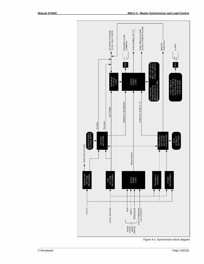
Manual 37444C MSLC-2 - Master Synchronizer and Load Control
© Woodward Page 133/220
Figure 4-1: Synchronizer block diagram
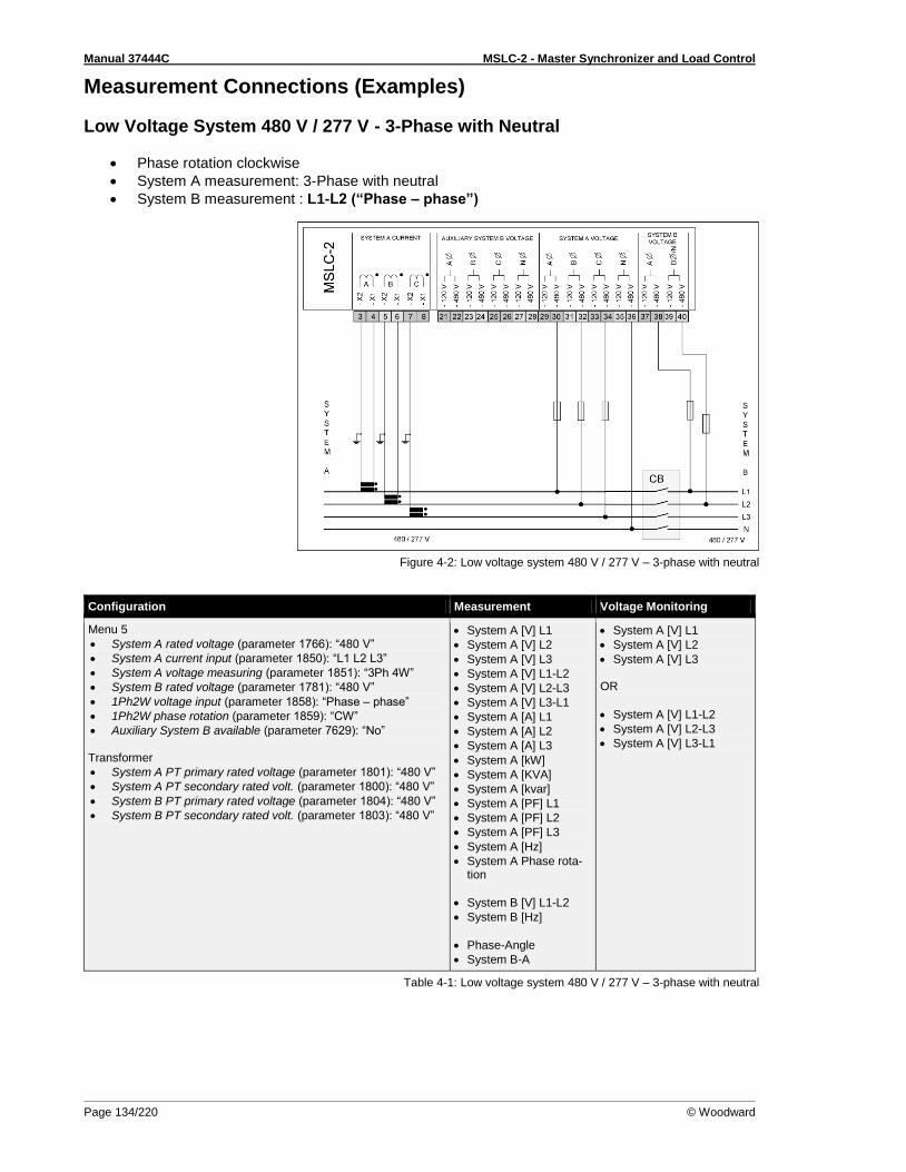
Manual 37444C MSLC-2 - Master Synchronizer and Load Control
Page 134/220 © Woodward
Measurement Connections (Examples)
Low Voltage System 480 V / 277 V - 3-Phase with Neutral
Phase rotation clockwise
System A measurement: 3-Phase with neutral
System B measurement : L1-L2 (“Phase – phase”)
Figure 4-2: Low voltage system 480 V / 277 V – 3-phase with neutral
Configuration Measurement Voltage Monitoring
Menu 5
System A rated voltage (parameter 1766): “480 V”
System A current input (parameter 1850): “L1 L2 L3”
System A voltage measuring (parameter 1851): “3Ph 4W”
System B rated voltage (parameter 1781): “480 V”
1Ph2W voltage input (parameter 1858): “Phase – phase”
1Ph2W phase rotation (parameter 1859): “CW”
Auxiliary System B available (parameter 7629): “No” Transformer
System A PT primary rated voltage (parameter 1801): “480 V”
System A PT secondary rated volt. (parameter 1800): “480 V”
System B PT primary rated voltage (parameter 1804): “480 V”
System B PT secondary rated volt. (parameter 1803): “480 V”
System A [V] L1
System A [V] L2
System A [V] L3
System A [V] L1-L2
System A [V] L2-L3
System A [V] L3-L1
System A [A] L1
System A [A] L2
System A [A] L3
System A [kW]
System A [KVA]
System A [kvar]
System A [PF] L1
System A [PF] L2
System A [PF] L3
System A [Hz]
System A Phase rota-tion
System B [V] L1-L2
System B [Hz]
Phase-Angle
System B-A
System A [V] L1
System A [V] L2
System A [V] L3 OR
System A [V] L1-L2
System A [V] L2-L3
System A [V] L3-L1
Table 4-1: Low voltage system 480 V / 277 V – 3-phase with neutral
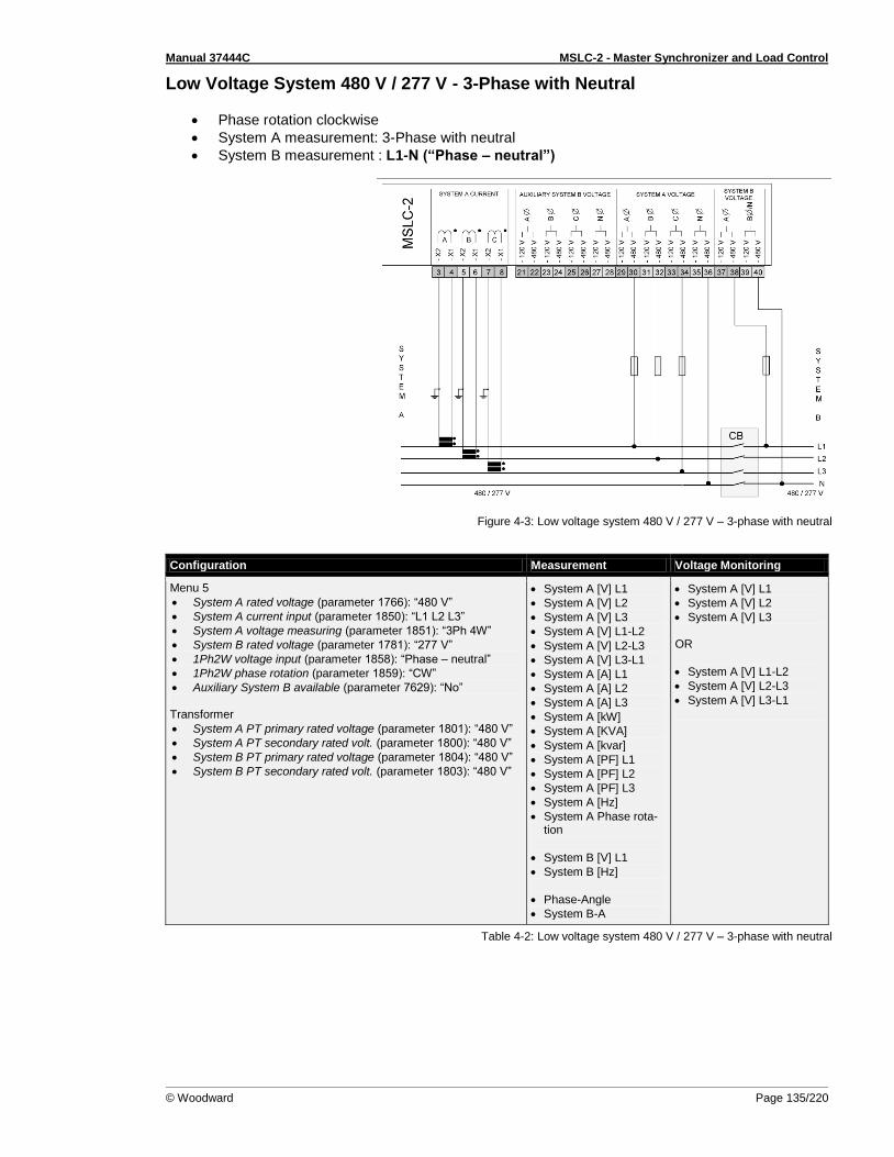
Manual 37444C MSLC-2 - Master Synchronizer and Load Control
© Woodward Page 135/220
Low Voltage System 480 V / 277 V - 3-Phase with Neutral
Phase rotation clockwise
System A measurement: 3-Phase with neutral
System B measurement : L1-N (“Phase – neutral”)
Figure 4-3: Low voltage system 480 V / 277 V – 3-phase with neutral
Configuration Measurement Voltage Monitoring
Menu 5
System A rated voltage (parameter 1766): “480 V”
System A current input (parameter 1850): “L1 L2 L3”
System A voltage measuring (parameter 1851): “3Ph 4W”
System B rated voltage (parameter 1781): “277 V”
1Ph2W voltage input (parameter 1858): “Phase – neutral”
1Ph2W phase rotation (parameter 1859): “CW”
Auxiliary System B available (parameter 7629): “No” Transformer
System A PT primary rated voltage (parameter 1801): “480 V”
System A PT secondary rated volt. (parameter 1800): “480 V”
System B PT primary rated voltage (parameter 1804): “480 V”
System B PT secondary rated volt. (parameter 1803): “480 V”
System A [V] L1
System A [V] L2
System A [V] L3
System A [V] L1-L2
System A [V] L2-L3
System A [V] L3-L1
System A [A] L1
System A [A] L2
System A [A] L3
System A [kW]
System A [KVA]
System A [kvar]
System A [PF] L1
System A [PF] L2
System A [PF] L3
System A [Hz]
System A Phase rota-tion
System B [V] L1
System B [Hz]
Phase-Angle
System B-A
System A [V] L1
System A [V] L2
System A [V] L3 OR
System A [V] L1-L2
System A [V] L2-L3
System A [V] L3-L1
Table 4-2: Low voltage system 480 V / 277 V – 3-phase with neutral
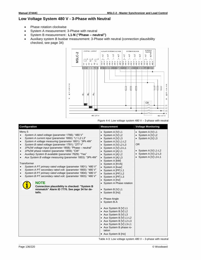
Manual 37444C MSLC-2 - Master Synchronizer and Load Control
Page 136/220 © Woodward
Low Voltage System 480 V - 3-Phase with Neutral
Phase rotation clockwise
System A measurement: 3-Phase with neutral
System B measurement : L1-N (“Phase – neutral”)
Auxiliary system B busbar measurement: 3-Phase with neutral (connection plausibility checked, see page 34)
Figure 4-4: Low voltage system 480 V – 3-phase with neutral
Configuration Measurement Voltage Monitoring
Menu 5
System A rated voltage (parameter 1766): “480 V”
System A current input (parameter 1850): “L1 L2 L3”
System A voltage measuring (parameter 1851): “3Ph 4W”
System B rated voltage (parameter 1781): “277 V”
1Ph2W voltage input (parameter 1858): “Phase – neutral”
1Ph2W phase rotation (parameter 1859): “CW”
Auxiliary System B available (parameter 7629): “Yes”
Aux System B voltage measuring (parameter 1853): “3Ph 4W” Transformer
System A PT primary rated voltage (parameter 1801): “480 V”
System A PT secondary rated volt. (parameter 1800): “480 V”
System B PT primary rated voltage (parameter 1804): “480 V”
System B PT secondary rated volt. (parameter 1803): “480 V”
NOTE Connection plausibility is checked: "System B mismatch" Alarm ID 7770. See page 34 for de-tails.
System A [V] L1
System A [V] L2
System A [V] L3
System A [V] L1-L2
System A [V] L2-L3
System A [V] L3-L1
System A [A] L1
System A [A] L2
System A [A] L3
System A [kW]
System A [KVA]
System A [kvar]
System A [PF] L1
System A [PF] L2
System A [PF] L3
System A [Hz]
System A Phase rotation
System B [V] L1
System B [Hz]
Phase-Angle
System B-A
Aux System B [V] L1
Aux System B [V] L2
Aux System B [V] L3
Aux System B [V] L1-L2
Aux System B [V] L2-L3
Aux System B [V] L3-L1
Aux System B phase ro-tation
Aux System B [Hz]
System A [V] L1
System A [V] L2
System A [V] L3 OR
System A [V] L1-L2
System A [V] L2-L3
System A [V] L3-L1
Table 4-3: Low voltage system 480 V – 3-phase with neutral

Manual 37444C MSLC-2 - Master Synchronizer and Load Control
© Woodward Page 137/220
Low Voltage System 600 V / 346 V - 3-Phase
Phase rotation clockwise
System A measurement: 3-Phase PT “Open Delta” (Phase L2 (B) is grounded at the MSLC-2 connection)
System B measurement: 1-Phase PT L1-L2 (“Phase – phase”)
Figure 4-5: Low voltage system 600 V / 346 V – 3-phase
Configuration Measurement Voltage Monitoring
Menu 5
System A rated voltage (parameter 1766): “600 V”
System A current input (parameter 1850): “L1 L2 L3”
System A voltage measuring (parameter 1851): “3Ph 4W OD”
System B rated voltage (parameter 1781): “600 V”
1Ph2W voltage input (parameter 1858): “Phase – phase”
1Ph2W phase rotation (parameter 1859): “CW”
Auxiliary System B available (parameter 7629): “No” Transformer
System A PT primary rated voltage (parameter 1801): “600 V”
System A PT secondary rated volt. (parameter 1800): “120 V”
System B PT primary rated voltage (parameter 1804): “600 V”
System B PT secondary rated volt. (parameter 1803): “120 V”
System A [V] L1-L2
System A [V] L2-L3
System A [V] L3-L1
System A [A] L1
System A [A] L2
System A [A] L3
System A [kW]
System A [KVA]
System A [kvar]
System A [PF] L1
System A [PF] L2
System A [PF] L3
System A [Hz]
System A Phase rota-tion
System B [V] L1-L2
System B [Hz]
Phase-Angle
System B-A
System A [V] L1-L2
System A [V] L2-L3
System A [V] L3-L1
Table 4-4: Low voltage system 600 V / 346 V – 3-phase

Manual 37444C MSLC-2 - Master Synchronizer and Load Control
Page 138/220 © Woodward
Low Voltage System 600 V / 346 V - 3-Phase
Phase rotation clockwise
System A measurement: 3-Phase PT “Open Delta” (Phase L2 (B) is grounded at the MSLC-2 connection)
System B measurement: 1-Phase PT L1-N (“Phase – neutral”)
Figure 4-6: Low voltage system 600 V / 346 V – 3-phase
Configuration Measurement Voltage Monitoring
Menu 5
System A rated voltage (parameter 1766): “600 V”
System A current input (parameter 1850): “L1 L2 L3”
System A voltage measuring (parameter 1851): “3Ph 4W OD”
System B rated voltage (parameter 1781): “346 V”
1Ph2W voltage input (parameter 1858): “Phase – neutral”
1Ph2W phase rotation (parameter 1859): “CW”
Auxiliary System B available (parameter 7629): “No” Transformer
System A PT primary rated voltage (parameter 1801): “600 V”
System A PT secondary rated volt. (parameter 1800): “120 V”
System B PT primary rated voltage (parameter 1804): “600 V”
System B PT secondary rated volt. (parameter 1803): “120 V”
System A [V] L1-L2
System A [V] L2-L3
System A [V] L3-L1
System A [A] L1
System A [A] L2
System A [A] L3
System A [kW]
System A [KVA]
System A [kvar]
System A [PF] L1
System A [PF] L2
System A [PF] L3
System A [Hz]
System A Phase rota-tion
System B [V] L1
System B [Hz]
Phase-Angle
System B-A
System A [V] L1-L2
System A [V] L2-L3
System A [V] L3-L1
Table 4-5: Low voltage system 600 V / 346 V – 3-phase
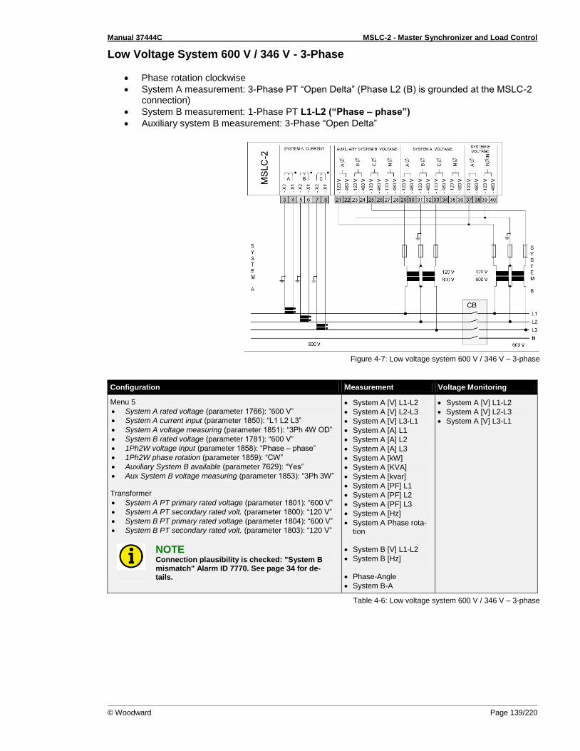
Manual 37444C MSLC-2 - Master Synchronizer and Load Control
© Woodward Page 139/220
Low Voltage System 600 V / 346 V - 3-Phase
Phase rotation clockwise
System A measurement: 3-Phase PT “Open Delta” (Phase L2 (B) is grounded at the MSLC-2 connection)
System B measurement: 1-Phase PT L1-L2 (“Phase – phase”)
Auxiliary system B measurement: 3-Phase “Open Delta”
Figure 4-7: Low voltage system 600 V / 346 V – 3-phase
Configuration Measurement Voltage Monitoring
Menu 5
System A rated voltage (parameter 1766): “600 V”
System A current input (parameter 1850): “L1 L2 L3”
System A voltage measuring (parameter 1851): “3Ph 4W OD”
System B rated voltage (parameter 1781): “600 V”
1Ph2W voltage input (parameter 1858): “Phase – phase”
1Ph2W phase rotation (parameter 1859): “CW”
Auxiliary System B available (parameter 7629): “Yes”
Aux System B voltage measuring (parameter 1853): “3Ph 3W” Transformer
System A PT primary rated voltage (parameter 1801): “600 V”
System A PT secondary rated volt. (parameter 1800): “120 V”
System B PT primary rated voltage (parameter 1804): “600 V”
System B PT secondary rated volt. (parameter 1803): “120 V”
NOTE Connection plausibility is checked: "System B mismatch" Alarm ID 7770. See page 34 for de-tails.
System A [V] L1-L2
System A [V] L2-L3
System A [V] L3-L1
System A [A] L1
System A [A] L2
System A [A] L3
System A [kW]
System A [KVA]
System A [kvar]
System A [PF] L1
System A [PF] L2
System A [PF] L3
System A [Hz]
System A Phase rota-tion
System B [V] L1-L2
System B [Hz]
Phase-Angle
System B-A
System A [V] L1-L2
System A [V] L2-L3
System A [V] L3-L1
Table 4-6: Low voltage system 600 V / 346 V – 3-phase

Manual 37444C MSLC-2 - Master Synchronizer and Load Control
Page 140/220 © Woodward
Low Voltage System 600 V / 346 V - 3-Phase with Neutral
Phase rotation clockwise
System A measurement: 3-Phase PT “wye” (Phase L2 (B) is grounded at the MSLC-2 connec-tion)
System B measurement: 1-Phase PT L1-L2 (“Phase – phase”)
Figure 4-8: Low voltage system 600 V / 346 V – 3-phase with neutral
Configuration Measurement Voltage Monitoring
Menu 5
System A rated voltage (parameter 1766): “600 V”
System A current input (parameter 1850): “L1 L2 L3”
System A voltage measuring (parameter 1851): “3Ph 4W”
System B rated voltage (parameter 1781): “600 V”
1Ph2W voltage input (parameter 1858): “Phase – phase”
1Ph2W phase rotation (parameter 1859): “CW”
Auxiliary System B available (parameter 7629): “No” Transformer
System A PT primary rated voltage (parameter 1801): “600 V”
System A PT secondary rated volt. (parameter 1800): “120 V”
System B PT primary rated voltage (parameter 1804): “600 V”
System B PT secondary rated volt. (parameter 1803): “120 V”
System A [V] L1-L2
System A [V] L2-L3
System A [V] L3-L1
System A [A] L1
System A [A] L2
System A [A] L3
System A [kW]
System A [KVA]
System A [kvar]
System A [PF] L1
System A [PF] L2
System A [PF] L3
System A [Hz]
System A Phase rota-tion
System B [V] L1-L2
System B [Hz]
Phase-Angle
System B-A
System A [V] L1-L2
System A [V] L2-L3
System A [V] L3-L1
Table 4-7: Low voltage system 600 V / 346 V – 3-phase with neutral
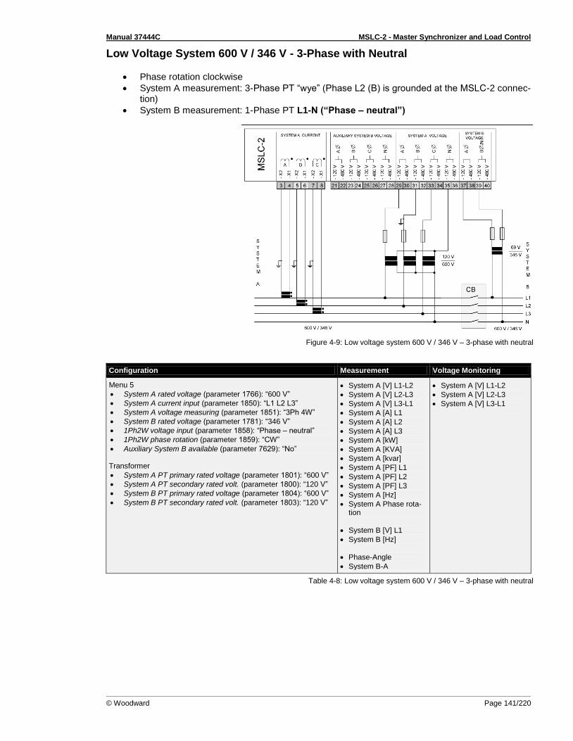
Manual 37444C MSLC-2 - Master Synchronizer and Load Control
© Woodward Page 141/220
Low Voltage System 600 V / 346 V - 3-Phase with Neutral
Phase rotation clockwise
System A measurement: 3-Phase PT “wye” (Phase L2 (B) is grounded at the MSLC-2 connec-tion)
System B measurement: 1-Phase PT L1-N (“Phase – neutral”)
Figure 4-9: Low voltage system 600 V / 346 V – 3-phase with neutral
Configuration Measurement Voltage Monitoring
Menu 5
System A rated voltage (parameter 1766): “600 V”
System A current input (parameter 1850): “L1 L2 L3”
System A voltage measuring (parameter 1851): “3Ph 4W”
System B rated voltage (parameter 1781): “346 V”
1Ph2W voltage input (parameter 1858): “Phase – neutral”
1Ph2W phase rotation (parameter 1859): “CW”
Auxiliary System B available (parameter 7629): “No” Transformer
System A PT primary rated voltage (parameter 1801): “600 V”
System A PT secondary rated volt. (parameter 1800): “120 V”
System B PT primary rated voltage (parameter 1804): “600 V”
System B PT secondary rated volt. (parameter 1803): “120 V”
System A [V] L1-L2
System A [V] L2-L3
System A [V] L3-L1
System A [A] L1
System A [A] L2
System A [A] L3
System A [kW]
System A [KVA]
System A [kvar]
System A [PF] L1
System A [PF] L2
System A [PF] L3
System A [Hz]
System A Phase rota-tion
System B [V] L1
System B [Hz]
Phase-Angle
System B-A
System A [V] L1-L2
System A [V] L2-L3
System A [V] L3-L1
Table 4-8: Low voltage system 600 V / 346 V – 3-phase with neutral

Manual 37444C MSLC-2 - Master Synchronizer and Load Control
Page 142/220 © Woodward
Low Voltage System 600 V / 346 V - 3-Phase with Neutral
Phase rotation clockwise
System A measurement: 3-Phase PT “wye”
System B measurement: 1-Phase PT L1-L2 (“Phase – phase”)
Auxiliary system B measurement: 3-Phase PT “wye”
Figure 4-10: Low voltage system 600 V / 346 V – 3-phase with neutral
Configuration Measurement Voltage Monitoring
Menu 5
System A rated voltage (parameter 1766): “600 V”
System A current input (parameter 1850): “L1 L2 L3”
System A voltage measuring (parameter 1851): “3Ph 4W”
System B rated voltage (parameter 1781): “600 V”
1Ph2W voltage input (parameter 1858): “Phase – phase”
1Ph2W phase rotation (parameter 1859): “CW”
Auxiliary System B available (parameter 7629): “Yes”
Aux System B voltage measuring (parameter 1853): “3Ph 4W” Transformer
System A PT primary rated voltage (parameter 1801): “600 V”
System A PT secondary rated volt. (parameter 1800): “120 V”
System B PT primary rated voltage (parameter 1804): “600 V”
System B PT secondary rated volt. (parameter 1803): “120 V”
NOTE Connection plausibility is checked: "System B mismatch" Alarm ID 7770. See page 34 for de-tails.
System A [V] L1-L2
System A [V] L2-L3
System A [V] L3-L1
System A [A] L1
System A [A] L2
System A [A] L3
System A [kW]
System A [KVA]
System A [kvar]
System A [PF] L1
System A [PF] L2
System A [PF] L3
System A [Hz]
System A Phase rota-tion
System B [V] L1-L2
System B [Hz]
Phase-Angle
System B-A
System A [V] L1-L2
System A [V] L2-L3
System A [V] L3-L1
Table 4-9: Low voltage system 600 V / 346 V – 3-phase with neutral
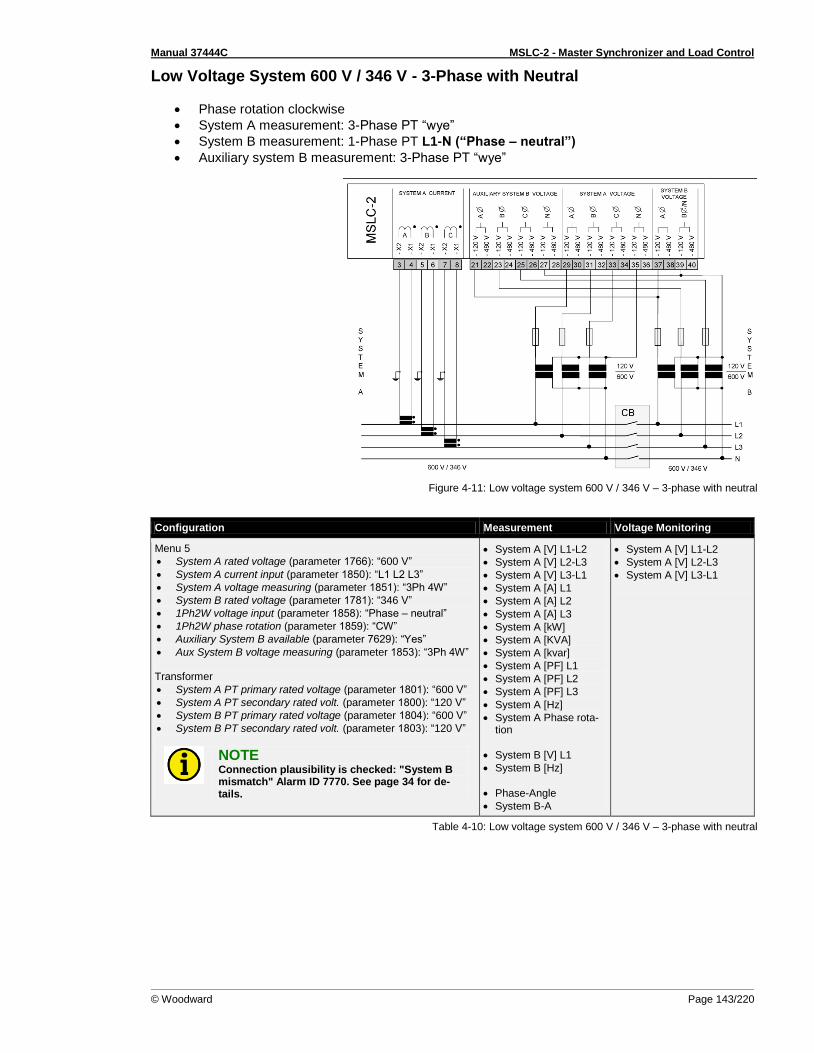
Manual 37444C MSLC-2 - Master Synchronizer and Load Control
© Woodward Page 143/220
Low Voltage System 600 V / 346 V - 3-Phase with Neutral
Phase rotation clockwise
System A measurement: 3-Phase PT “wye”
System B measurement: 1-Phase PT L1-N (“Phase – neutral”)
Auxiliary system B measurement: 3-Phase PT “wye”
Figure 4-11: Low voltage system 600 V / 346 V – 3-phase with neutral
Configuration Measurement Voltage Monitoring
Menu 5
System A rated voltage (parameter 1766): “600 V”
System A current input (parameter 1850): “L1 L2 L3”
System A voltage measuring (parameter 1851): “3Ph 4W”
System B rated voltage (parameter 1781): “346 V”
1Ph2W voltage input (parameter 1858): “Phase – neutral”
1Ph2W phase rotation (parameter 1859): “CW”
Auxiliary System B available (parameter 7629): “Yes”
Aux System B voltage measuring (parameter 1853): “3Ph 4W” Transformer
System A PT primary rated voltage (parameter 1801): “600 V”
System A PT secondary rated volt. (parameter 1800): “120 V”
System B PT primary rated voltage (parameter 1804): “600 V”
System B PT secondary rated volt. (parameter 1803): “120 V”
NOTE Connection plausibility is checked: "System B mismatch" Alarm ID 7770. See page 34 for de-tails.
System A [V] L1-L2
System A [V] L2-L3
System A [V] L3-L1
System A [A] L1
System A [A] L2
System A [A] L3
System A [kW]
System A [KVA]
System A [kvar]
System A [PF] L1
System A [PF] L2
System A [PF] L3
System A [Hz]
System A Phase rota-tion
System B [V] L1
System B [Hz]
Phase-Angle
System B-A
System A [V] L1-L2
System A [V] L2-L3
System A [V] L3-L1
Table 4-10: Low voltage system 600 V / 346 V – 3-phase with neutral
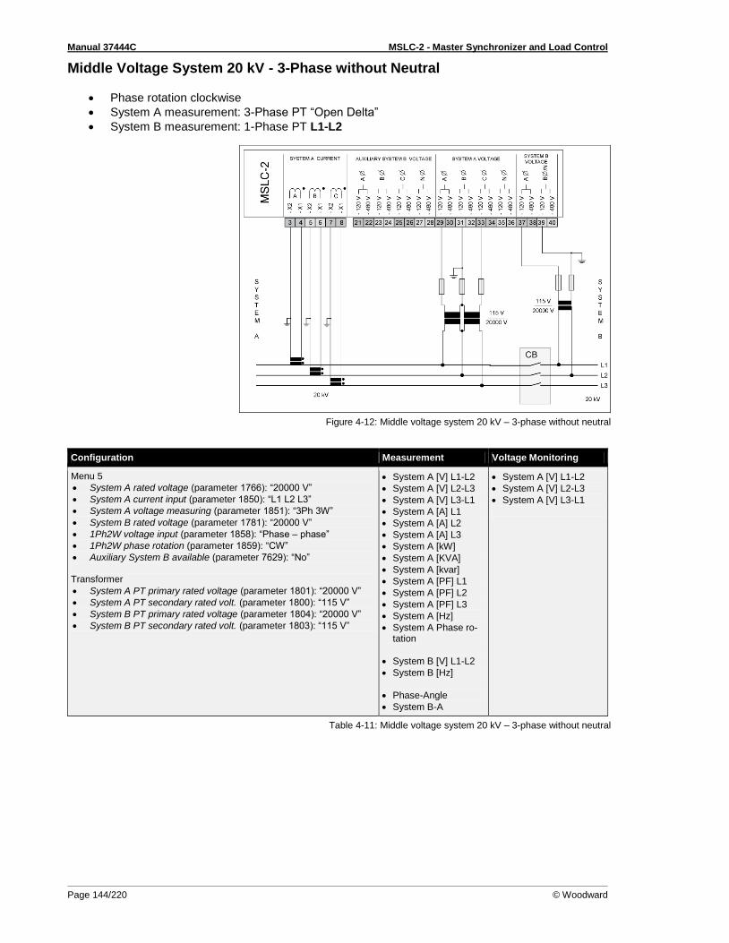
Manual 37444C MSLC-2 - Master Synchronizer and Load Control
Page 144/220 © Woodward
Middle Voltage System 20 kV - 3-Phase without Neutral
Phase rotation clockwise
System A measurement: 3-Phase PT “Open Delta”
System B measurement: 1-Phase PT L1-L2
Figure 4-12: Middle voltage system 20 kV – 3-phase without neutral
Configuration Measurement Voltage Monitoring
Menu 5
System A rated voltage (parameter 1766): “20000 V”
System A current input (parameter 1850): “L1 L2 L3”
System A voltage measuring (parameter 1851): “3Ph 3W”
System B rated voltage (parameter 1781): “20000 V”
1Ph2W voltage input (parameter 1858): “Phase – phase”
1Ph2W phase rotation (parameter 1859): “CW”
Auxiliary System B available (parameter 7629): “No” Transformer
System A PT primary rated voltage (parameter 1801): “20000 V”
System A PT secondary rated volt. (parameter 1800): “115 V”
System B PT primary rated voltage (parameter 1804): “20000 V”
System B PT secondary rated volt. (parameter 1803): “115 V”
System A [V] L1-L2
System A [V] L2-L3
System A [V] L3-L1
System A [A] L1
System A [A] L2
System A [A] L3
System A [kW]
System A [KVA]
System A [kvar]
System A [PF] L1
System A [PF] L2
System A [PF] L3
System A [Hz]
System A Phase ro-tation
System B [V] L1-L2
System B [Hz]
Phase-Angle
System B-A
System A [V] L1-L2
System A [V] L2-L3
System A [V] L3-L1
Table 4-11: Middle voltage system 20 kV – 3-phase without neutral
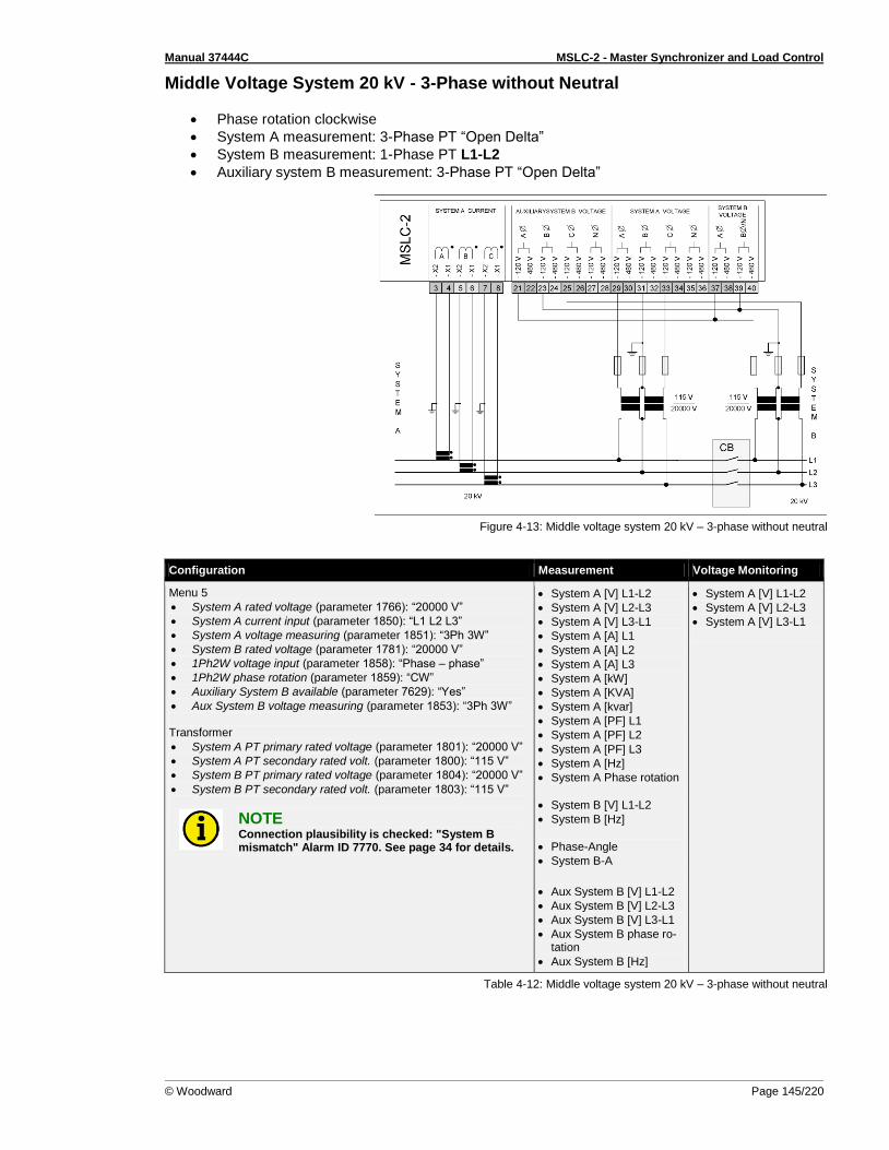
Manual 37444C MSLC-2 - Master Synchronizer and Load Control
© Woodward Page 145/220
Middle Voltage System 20 kV - 3-Phase without Neutral
Phase rotation clockwise
System A measurement: 3-Phase PT “Open Delta”
System B measurement: 1-Phase PT L1-L2
Auxiliary system B measurement: 3-Phase PT “Open Delta”
Figure 4-13: Middle voltage system 20 kV – 3-phase without neutral
Configuration Measurement Voltage Monitoring
Menu 5
System A rated voltage (parameter 1766): “20000 V”
System A current input (parameter 1850): “L1 L2 L3”
System A voltage measuring (parameter 1851): “3Ph 3W”
System B rated voltage (parameter 1781): “20000 V”
1Ph2W voltage input (parameter 1858): “Phase – phase”
1Ph2W phase rotation (parameter 1859): “CW”
Auxiliary System B available (parameter 7629): “Yes”
Aux System B voltage measuring (parameter 1853): “3Ph 3W” Transformer
System A PT primary rated voltage (parameter 1801): “20000 V”
System A PT secondary rated volt. (parameter 1800): “115 V”
System B PT primary rated voltage (parameter 1804): “20000 V”
System B PT secondary rated volt. (parameter 1803): “115 V”
NOTE Connection plausibility is checked: "System B mismatch" Alarm ID 7770. See page 34 for details.
System A [V] L1-L2
System A [V] L2-L3
System A [V] L3-L1
System A [A] L1
System A [A] L2
System A [A] L3
System A [kW]
System A [KVA]
System A [kvar]
System A [PF] L1
System A [PF] L2
System A [PF] L3
System A [Hz]
System A Phase rotation
System B [V] L1-L2
System B [Hz]
Phase-Angle
System B-A
Aux System B [V] L1-L2
Aux System B [V] L2-L3
Aux System B [V] L3-L1
Aux System B phase ro-tation
Aux System B [Hz]
System A [V] L1-L2
System A [V] L2-L3
System A [V] L3-L1
Table 4-12: Middle voltage system 20 kV – 3-phase without neutral
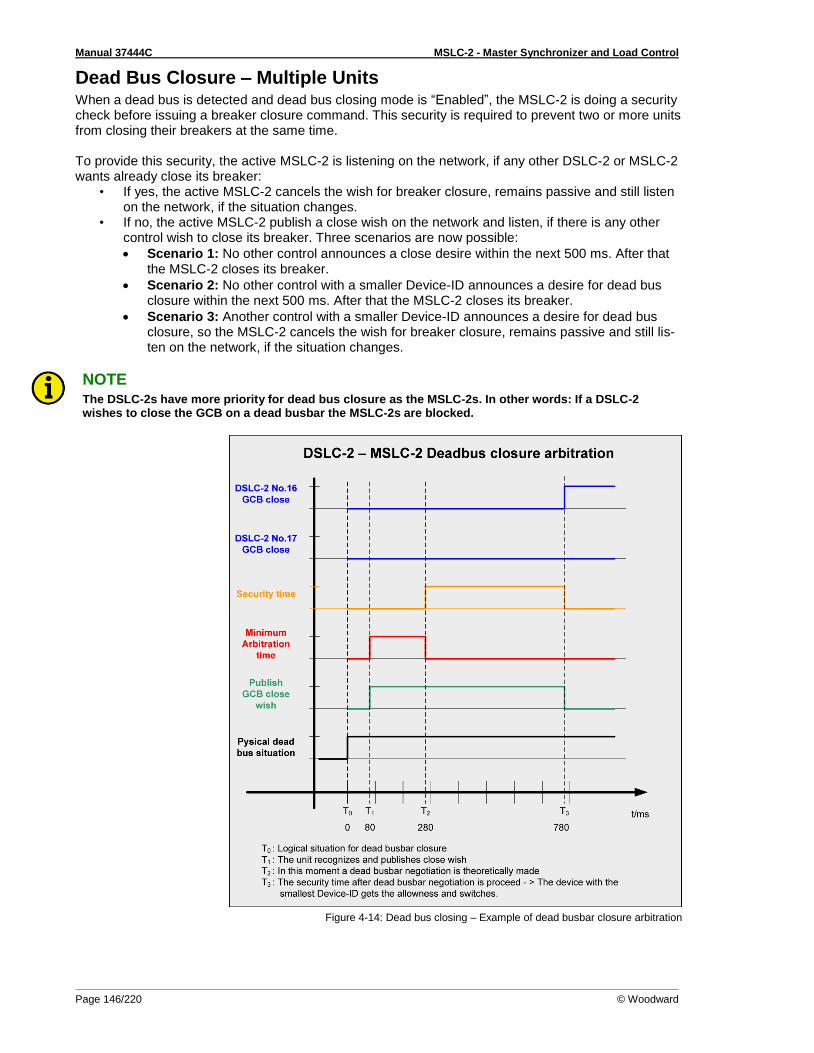
Manual 37444C MSLC-2 - Master Synchronizer and Load Control
Page 146/220 © Woodward
Dead Bus Closure – Multiple Units When a dead bus is detected and dead bus closing mode is “Enabled”, the MSLC-2 is doing a security check before issuing a breaker closure command. This security is required to prevent two or more units from closing their breakers at the same time. To provide this security, the active MSLC-2 is listening on the network, if any other DSLC-2 or MSLC-2 wants already close its breaker:
• If yes, the active MSLC-2 cancels the wish for breaker closure, remains passive and still listen on the network, if the situation changes.
• If no, the active MSLC-2 publish a close wish on the network and listen, if there is any other control wish to close its breaker. Three scenarios are now possible:
Scenario 1: No other control announces a close desire within the next 500 ms. After that the MSLC-2 closes its breaker.
Scenario 2: No other control with a smaller Device-ID announces a desire for dead bus closure within the next 500 ms. After that the MSLC-2 closes its breaker.
Scenario 3: Another control with a smaller Device-ID announces a desire for dead bus closure, so the MSLC-2 cancels the wish for breaker closure, remains passive and still lis-ten on the network, if the situation changes.
NOTE The DSLC-2s have more priority for dead bus closure as the MSLC-2s. In other words: If a DSLC-2 wishes to close the GCB on a dead busbar the MSLC-2s are blocked.
Figure 4-14: Dead bus closing – Example of dead busbar closure arbitration
Manual 37444C MSLC-2 - Master Synchronizer and Load Control
© Woodward Page 147/220
Deadbus Closure Mismatch Alarm When a deadbus is detected and dead bus closing mode is activated by DI “Run” or DI “Permissive”, the MSLC-2 is doing an additional security check before issuing a breaker closure command.
If there is a breaker (GCB and/or MCB) closed in the own segment and/or (own segment+1), then the alarm “Deadbus closure mismatch” is set and the MSLC-2 will not close to a deadbus.
The alarm “Deadbus closure mismatch” (parameter 4620) shows the deadbus plausibility in ToolKit Menu 8. Addi-tional, a Relay output: Alarm1, Alarm2 or Alarm3 can be assigned within ID 7598 in ToolKit Menu 0. Finally the deadbus closure mismatch alarm is added internally to the “Centralized Alarm” and can be first detected therefore in the ToolKit Homepage with the LED “Centralized Alarm”. The Deadbus closure mismatch alarm is set with following detailed conditions:
Utility MSLC2: Precondition: Start Deadbus closure with energizing DI “Run” or DI “Permissive”
A GCB in the own segment is closed and the busbar is dead
Another MCB in the own segment is closed and the busbar is dead
Tie MSLC2: Precondition: Start Deadbus closure with energizing DI “Run” or DI “Permissive”
GCB closed and busbar is dead on system A
GCB closed and busbar is dead on system B
MCB closed and busbar is dead on system A
MCB closed and busbar is dead on system B The deadbus closure mismatch alarm is reset (self acknowledge) with following conditions:
Still deadbus but no closed breaker in the same segment (via breaker open feedback received)
Deadbus changes to “Voltage ok” on busbar in the detected segment with the closed breaker
De energize DI “Run” or DI “Permissive”

Manual 37444C MSLC-2 - Master Synchronizer and Load Control
Page 148/220 © Woodward
Voltage Matching The voltages of two systems in parallel must be matched within a small percentage to minimize the re-active power flow in the system. If a local plant is paralleled to the main grid with unequal voltages, the local plant will, in most cases, follow the utility voltage. The difference in voltages results in reactive currents flowing in the system with subsequent lowered system efficiency. If the system is initially at a lower voltage than the utility, reactive power will be absorbed by the sys-tem. If the system voltage was initially higher, the local plant will provide extra reactive power to the utility. In either case the breaker across which the parallel is made will experience unnecessary wear and tear created by the arcing across different voltages. The MSLC-2 measures the RMS values of the voltages. The synchronizer issues appropriate raise or lower commands, or voltage bias adjustment to all of the DSLC-2 controls over the Ethernet network. The MSLC-2 will continue this process until the difference between System B and System A voltage is within a specified window. The automatic voltage matching function may be enabled or disabled with a configuration setpoint. When enabled, voltage matching will occur in both the “Check” and “Run” modes and is verified to be within the window in the “Permissive” mode.
Phase Matching Synchronizing The phase matching synchronizer mode corrects the frequency and phase of the system A to lock it to the system B frequency and phase. Phase matching synchronizing can be configured (parameter 5730) in the unit. With activation of the synchronizer the MSLC-2 begins to control at first the frequency to minimize the frequency difference between system B and system A. When the frequency window comes into the range of phase matching start, see configuration Phase matching df-start (parameter 5506), the synchronizer watches the phase relation. Therefore the frequency setpoint to the DSLC-2 increases or decreases and result in speed biasing to the engine depending on whether the slip is faster or slower than the system A. Proportional and integral gain adjustments are provided to allow stable operation of the automatic synchronizer over a wide range of system dynamics.
Slip Frequency Synchronizing In certain applications the initial power flow can be either from or to the utility. Depending on the re-quirement, the local bus can be brought into parallel with a slightly higher or lower frequency than the mains. This can be provided by the parameter Slip frequency setpoint offset (parameter 4712). The slip frequency method is configured by the configuration Synchronization CB (parameter 5730). The syn-chronizer automatically controls the connected generator at the specified slip frequency. The MSLC-2 outputs an error signal over the network to the DSLC-2 controls to change their bias on the speed con-trols. Gain and stability adjustments to the slip frequency proportional and integral gain controller are provided to allow stable operation of the automatic synchronizer function over a wide range of system dynamics (parameter 4539, parameter 4540).
Permissive Mode / Synch-Check Function The synch-check function determines when frequency, phase and voltage are within the configured settings for proper synchronization before issuing a breaker closure command. The Setpoint frequency (parameter 4627) and Setpoint voltage (parameter 4628) are not used to drive system B into synchro-nization. The MSLC-2 can be manually controlled using the setpoint raise/ lower and voltage raise/ lower discrete inputs. The system A and system B voltage comparison is made independent of the voltage matching function being enabled. When all conditions of voltage and phase are met, then a
constant breaker closure command is given.
Manual 37444C MSLC-2 - Master Synchronizer and Load Control
© Woodward Page 149/220
GCB Maximum Closing Attempts The synchronizer allows multiple breaker closure attempts to an active or dead bus. The control pro-vides setpoints for the number of close attempts (parameter 3419) and the reclosure delay timing (pa-rameter 4534). The synchronizer feature has 2 alarms, Reclose limit alarm (parameter 7556) and the Synchronizer timeout alarm (parameter 7557). These alarms will affect the synchronizer differently be-tween an active or dead bus.
Dead bus closing If both alarms are disabled, you will receive infinite breaker closure attempts. If one or both alarms are enabled, when that alarm setting is reached, an alarm is received and no more breaker close attempts will be given. This is important when you have multiple utilities attempting to close to a dead bus. The MSLC-2 that receives the dead bus token will not pass the dead bus token until it receives an alarm. So having 1 or 2 close attempts is preferred in a multiple utility application.
Active bus closing If both alarms are disabled, you will receive infinite breaker closure attempts. If one or both alarms are enabled, when that alarm setting is reached, an alarm is received but the synchronizer will keep provid-ing breaker closure commands until a “CB Aux” feedback is received or the “Run” or “Permissive” input is removed.
Auto re-synchronization The Auto re-synchronization feature (parameter 7514), when enabled, allows the MSLC-2 to attempt to reclose the breaker if the “CB Aux” feedback is opened and the MSLC-2 still has a “Run” or “Permis-sive” input closed. The auto re-synchronizer feature becomes active after a successful breaker closure is received. Then if the breaker feedback (CB Aux) is opened and the “Run” or “Permissive” input is still closed, the MSLC-2 will attempt to close the breaker when in the synchronizer specifications. If config-ured for “Disabled”, no attempt at synchronization will be made until the “Run” input is then opened and reclosed. This is active even when a utility unload command is given and the MSLC-2 opens the breaker. With auto re-synchronization “Enabled”, the synchronizer will become active.
NOTE Woodward suggest to remove the “Run” or “Permissive” input after a successful breaker closure has been received and have the “Run” or “Permissive” input reclosed if the breaker opens and it is safe to reclose it.
Reclose limit alarm When the Reclose limit alarm (parameter 7556) is “Enabled” an independent monitor counts in the background the number of close attempts. When the number of close attempts matches the configura-ble number of closing attempts (parameter 3419) an alarm flag will be issued. This alarm flag is auto-matically considered when a dead busbar closure is executed. When during the dead busbar closure, the reclose limit alarm becomes active; the dead busbar closure permission will be passed to another MSLC-2. If the Reclose limit alarm (parameter 7556) is “Disabled”, the MSLC-2 will have an infinite number of at-
tempts to close the breaker.
Synchronizer Timer The synchronizer function is equipped with three adjustable timers.
1. The CB close hold time (parameter 3417) determines the amount of time the control maintains the breaker close command.
2. The Synchronizer timeout (parameter 3063) when the Synchronizer timeout alarm (parameter 7557) is “Enabled”. The alarm is removable by de-energized run signal.
3. The Reclose delay (parameter 4534) which is the time delay between the single close com-mands.
When “Enabled” the synchronizer timer starts when the “Run” switch is closed. It is not active in the check or permissive modes. If no breaker closure is received by the end of the timer, a synchronizer timeout alarm is received and the MSLC-2 will stop the synchronizing process. If the “Run” input is re-moved, the alarm is reset and when the “Run” input is closed the synchronizer process will be active.
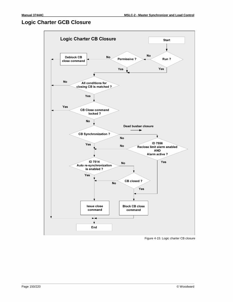
Manual 37444C MSLC-2 - Master Synchronizer and Load Control
Page 150/220 © Woodward
Logic Charter GCB Closure
Figure 4-15: Logic charter CB closure
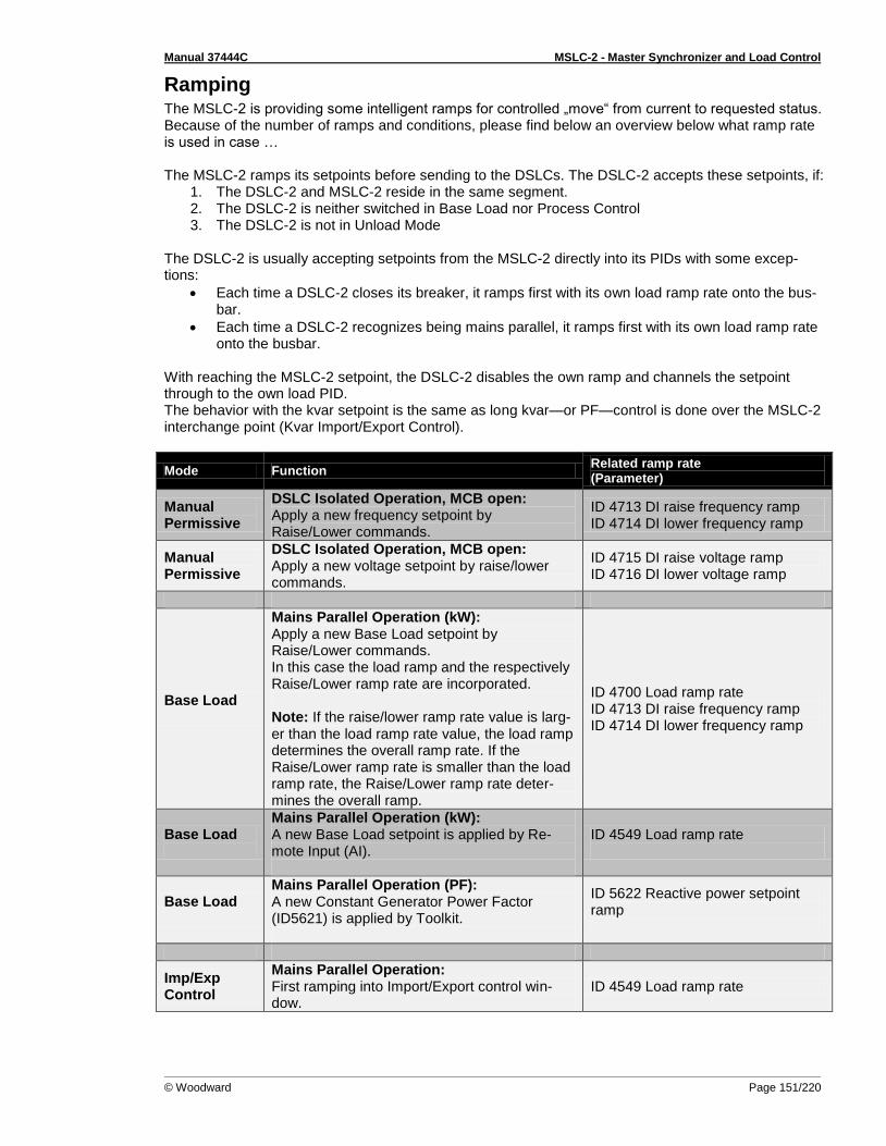
Manual 37444C MSLC-2 - Master Synchronizer and Load Control
© Woodward Page 151/220
Ramping The MSLC-2 is providing some intelligent ramps for controlled „move“ from current to requested status. Because of the number of ramps and conditions, please find below an overview below what ramp rate is used in case … The MSLC-2 ramps its setpoints before sending to the DSLCs. The DSLC-2 accepts these setpoints, if:
1. The DSLC-2 and MSLC-2 reside in the same segment. 2. The DSLC-2 is neither switched in Base Load nor Process Control 3. The DSLC-2 is not in Unload Mode
The DSLC-2 is usually accepting setpoints from the MSLC-2 directly into its PIDs with some excep-tions:
Each time a DSLC-2 closes its breaker, it ramps first with its own load ramp rate onto the bus-bar.
Each time a DSLC-2 recognizes being mains parallel, it ramps first with its own load ramp rate onto the busbar.
With reaching the MSLC-2 setpoint, the DSLC-2 disables the own ramp and channels the setpoint through to the own load PID. The behavior with the kvar setpoint is the same as long kvar—or PF—control is done over the MSLC-2 interchange point (Kvar Import/Export Control).
Mode Function Related ramp rate (Parameter)
Manual Permissive
DSLC Isolated Operation, MCB open: Apply a new frequency setpoint by Raise/Lower commands.
ID 4713 DI raise frequency ramp ID 4714 DI lower frequency ramp
Manual Permissive
DSLC Isolated Operation, MCB open: Apply a new voltage setpoint by raise/lower commands.
ID 4715 DI raise voltage ramp ID 4716 DI lower voltage ramp
Base Load
Mains Parallel Operation (kW): Apply a new Base Load setpoint by Raise/Lower commands. In this case the load ramp and the respectively Raise/Lower ramp rate are incorporated. Note: If the raise/lower ramp rate value is larg-er than the load ramp rate value, the load ramp determines the overall ramp rate. If the Raise/Lower ramp rate is smaller than the load ramp rate, the Raise/Lower ramp rate deter-mines the overall ramp.
ID 4700 Load ramp rate ID 4713 DI raise frequency ramp ID 4714 DI lower frequency ramp
Base Load
Mains Parallel Operation (kW): A new Base Load setpoint is applied by Re-mote Input (AI).
ID 4549 Load ramp rate
Base Load
Mains Parallel Operation (PF): A new Constant Generator Power Factor (ID5621) is applied by Toolkit.
ID 5622 Reactive power setpoint ramp
Imp/Exp Control
Mains Parallel Operation: First ramping into Import/Export control win-dow.
ID 4549 Load ramp rate
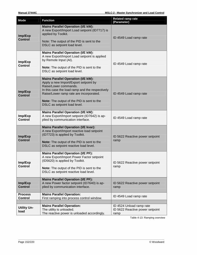
Manual 37444C MSLC-2 - Master Synchronizer and Load Control
Page 152/220 © Woodward
Mode Function Related ramp rate (Parameter)
Imp/Exp Control
Mains Parallel Operation (I/E kW): A new Export/Import Load setpoint (ID7717) is applied by Toolkit. Note: The output of the PID is sent to the DSLC as setpoint load level.
ID 4549 Load ramp rate
Imp/Exp Control
Mains Parallel Operation (I/E kW): A new Export/Import Load setpoint is applied by Remote Input (AI). Note: The output of the PID is sent to the DSLC as setpoint load level.
ID 4549 Load ramp rate
Imp/Exp Control
Mains Parallel Operation (I/E kW): Apply a new Import/Export setpoint by Raise/Lower commands. In this case the load ramp and the respectively Raise/Lower ramp rate are incorporated. Note: The output of the PID is sent to the DSLC as setpoint load level.
ID 4549 Load ramp rate
Imp/Exp Control
Mains Parallel Operation (I/E kW): A new Export/Import setpoint (ID7642) is ap-plied by communication interface.
ID 4549 Load ramp rate
Imp/Exp Control
Mains Parallel Operation (I/E kvar): A new Export/Import reactive load setpoint (ID7723) is applied by Toolkit. Note: The output of the PID is sent to the DSLC as setpoint reactive load level.
ID 5622 Reactive power setpoint ramp
Imp/Exp Control
Mains Parallel Operation (I/E PF): A new Export/Import Power Factor setpoint (ID5620) is applied by Toolkit. Note: The output of the PID is sent to the DSLC as setpoint reactive load level.
ID 5622 Reactive power setpoint ramp
Imp/Exp Control
Mains Parallel Operation (I/E PF): A new Power factor setpoint (ID7640) is ap-plied by communication interface.
ID 5622 Reactive power setpoint ramp
Process Control
Mains Parallel Operation: First ramping into process control window.
ID 4549 Load ramp rate
Utility Un-load
Mains Parallel Operation: The utility is unloaded. The reactive power is unloaded accordingly.
ID 4524 Unload ramp rate ID 5622 Reactive power setpoint ramp
Table 4-13: Ramping overview
Manual 37444C MSLC-2 - Master Synchronizer and Load Control
© Woodward Page 153/220
Manual Synchronizing
≡≡≡≡≡≡≡≡≡≡≡≡≡≡≡≡≡≡≡≡≡≡≡≡≡ The manual synchronizer is activated / deactivated under the following conditions. Activated Deactivated
MCB/tie-breaker = open AND
DI “Check” (active) AND
DI “Permissive” (active)
Breaker feedback DI “CB Aux” = closed
OR
DI “Check” (not active) AND
DI “Permissive” (not active) The MSLC-2 is before and during the manual synchronization in Load control mode (parameter 4603) “Off Line”, and in the Synchronizer mode (parameter 4602) “Off”, independent if the MSLC-2 is config-ured to utility or tie.
Frequency Setpoint It is possible with discrete input “Setpoint Raise” or discrete input “Setpoint Lower” to adjust the Setpoint frequency (parameter 4627) of connected DSLCs, which are in the same segment, up and down (ramp rate adjustable from 0,01%rated/s to 100,00%rated/s (0.01%rated/s) with parameter 4713, parameter 4714). The setpoint frequency is the direct output of the parameter Setpoint frequency (pa-rameter 4627) is transferred in Hz to the DSLCs. The setpoint frequency is limited due to the parame-ters Upper frequency limit (parameter 5802) and Lower frequency limit (parameter 5803). The operat-ing ranges of these parameters are adjustable in Menu 5.
Upper frequency limit (parameter 5802) | Range: 100 to 150% | Default: 110% = 66 Hz (with rated frequency = 60 Hz)
Lower frequency limit (parameter 5803) | Range: 50 to 100% | Default: 90% = 54 Hz (with rat-ed frequency = 60 Hz)
NOTE Frequency setpoint DSLC-2:
Received via parameter Setpoint frequency (parameter 4627) | Range: 54 to 66 Hz (limited 90 to 110% from rated frequency, for example 60 Hz)
Voltage Setpoint It is possible with discrete input “Voltage Raise” or discrete input “Voltage Lower” to adjust the Setpoint voltage (parameter 4628) of connected DSLCs, which are in the same segment, up and down (ramp rate adjustable from 0,01%rated/s to 100,00%rated/s (0.05%rated/s) with parameter 4715, parameter 4716) t. The setpoint voltage is the direct output of the parameter Setpoint voltage (parameter 4628) is transferred in% to the DSLCs. The setpoint frequency is limited due to the parameters Upper voltage limit (parameter 5800) and Lower voltage limit (parameter 5801). The operating ranges of these pa-rameters are adjustable in Menu 5.
Upper voltage limit (parameter 5800) | Range: 100 to 150% | Default: 110% = 440 V (of rated voltage = 400 V)
Lower voltage limit (parameter 5801) | Range: 50 to 100% | Default: 90% = 360 V (of rated voltage = 400 V)
NOTE Voltage setpoint DSLC-2:
Received via parameter Setpoint voltage (parameter 4628) | Range: 90 to 110% (limited 80 to 120% from rated voltage)
Manual 37444C MSLC-2 - Master Synchronizer and Load Control
Page 154/220 © Woodward
Breaker Close The MCB/tie-breaker can be closed manually when system B frequency and voltage are in range.
CAUTION The rotation field of system A and system B must be measured. They must have the same direction – CW or CCW.
Reset Frequency / Voltage Setpoints Back To Rated (50 Hz or 60 Hz)
MSLC-2 configured as utility breaker control: MCB/tie-breaker = closed and breaker feed-back mains parallel operation
MSLC-2 configured as tie-breaker control: Manual synchronizer = off and MCB/tie-breaker = closed

Manual 37444C MSLC-2 - Master Synchronizer and Load Control
© Woodward Page 155/220
Chapter 5. Real Power Control Description
Introduction
≡≡≡≡≡≡≡≡≡≡≡≡≡≡≡≡≡≡≡≡≡≡≡≡≡ The MSLC-2 control provides several modes of generator load operation. These are:
• Base loading o Automatic control of generators kW and constant generator PF control
• Import/export level control o Automatic control of the systems import or export power and either var or power factor
control or constant generator PF control • Process control
o Automatic control of a process signal with either var or power factor control or constant generator PF control
• Utility unload o The ability to transfer the system load from the utility to the generators with the utility
breaker being opened at the Utility unload trip (parameter 4506) level
MSLC-2 / DSLC-2 Interface
≡≡≡≡≡≡≡≡≡≡≡≡≡≡≡≡≡≡≡≡≡≡≡≡≡ The MSLC-2 is able to control load and reactive load with only active DSLC-2 controls which are con-nected to the same bus segment and are in the load sharing mode. DSLC-2s that are in base load or process control cannot be controlled by a MSLC-2. The MSLC-2 can synchronize multiple DSLC-2s to the utility. Once the utility breaker is closed, the MSLC-2 must be placed in a load control mode. These are base load, import/export process control or utility unload. MSLC-2s in the tie-breaker mode will synchronize and close the tie-breaker to connect different bus segments but will not have any load control capabilities.
NOTE The DSLC-2 will show it is in the base load mode (parameter 4603) when being controlled by a MSLC-2.
Base Load Mode
≡≡≡≡≡≡≡≡≡≡≡≡≡≡≡≡≡≡≡≡≡≡≡≡≡ The MSLC-2 takes the system load percentage immediately upon entering the base load mode for the initial base load reference setting. This is true when synchronizing to the utility or transferring from im-port/export mode to base load. The base load reference can be moved by using the setpoint “Raise” or “Lower” discrete inputs with an option to use the remote analog input to control the reference. The DSLC-2 controls will maintain the system load percentage being provided by the MSLC-2 with the utili-ty picking up all load swings. Using the setpoint lower input will decrease the system load percentage, thus unloading the generators and transferring the load to the utility. The MSLC-2 has a Generator un-load trip (parameter 3125) level that activates the Lcl. / generator breaker open relay. This output can be used to open a group breaker or to signal the DSLC-2s to open the generator breaker. This breaker stays active for 400 milliseconds. When in base load control the reactive power control will automatical-ly be the constant generator PF mode. While unloading the kW of the generators you will need to un-load the reactive power. The MSLC-2 will change the constant generator PF control reference to 1.0 when the system load percentage reaches the Generator unload trip (parameter 3125) setpoint.
Manual 37444C MSLC-2 - Master Synchronizer and Load Control
Page 156/220 © Woodward
Import / Export Mode
≡≡≡≡≡≡≡≡≡≡≡≡≡≡≡≡≡≡≡≡≡≡≡≡≡ The MSLC-2 measures the real power flow to or from the main power grid. It then controls all active DSLC-2s by controlling the system load percentage signal. The individual DSLC-2 controls will control to this percentage of their rated loads and the MSLC-2 will adjust this system load up or down to achieve the proper import/export level. The system load percentage is limited to a 0 to 100% signal so that overload or reverse power of the generators will never occur. When in import / export mode the PID control is located in Menu 2. The DSLC-2 controls are using the base load PID (Menu 2) to control at the reference signal being sent from the MSLC-2. The reactive power can be configured for var, PF, or constant generator PF control.
NOTE Any DSLC-2 set for base loading will maintain its individually set base load, regardless of the MSLC-2 signal. Therefore, a sufficient number of generators must be in isochronous load sharing in order to handle plant load swings and still maintain the import/export level. The DSLC-2s Load control mode (parameter 4603) will indicate base load mode when being controlled by the MSLC-2.
Process Control Mode
≡≡≡≡≡≡≡≡≡≡≡≡≡≡≡≡≡≡≡≡≡≡≡≡≡ The MSLC-2 controls the DSLC-2 equipped generators by adjusting the system load. The MSLC-2 will control the system load to maintain the process input signal is equal to the process reference The MSLC-2 is limited to changing the reference signal to the DSLC-2 controls between 0 and 100%. The reactive power can be configured for var, PF, or constant generator PF control.
Remote Control
≡≡≡≡≡≡≡≡≡≡≡≡≡≡≡≡≡≡≡≡≡≡≡≡≡ In any of the above modes, the reference can be determined by an analog signal input at terminals 83 to 85. The remote mode is selected by activating both the setpoint raise and lower at the same time. Menu 6 determines the scaling and the engineering units. The remote load reference signal can be a base load, import / export or a process control value. The reactive load analog input at terminals 89 to 91 can be used for a power factor setpoint control or a constant generator power factor control reference. Menu 6 determines the scaling.
Automatic Power Transfer Control Functions
≡≡≡≡≡≡≡≡≡≡≡≡≡≡≡≡≡≡≡≡≡≡≡≡≡
Ramping Between Modes Whenever the mode of load control is changed, the MSLC-2 will ramp at a user chosen rate until it is within 5% of its new reference. Then, it will begin dynamic control. This provides smooth (bumpless) transitions between all modes.
Utility Unload The utility unload feature is available with the MSLC-2 in base load, import / export or process mode. When the utility unload command is issued, the MSLC-2 will adjust the Setpoint load level (parameter 4629) until a specified level around the zero power transfer point is obtained. It will then issue a utility breaker open command. The Utility unload trip (parameter 4506) determines at which power value the tolerance for opening the breaker is reached. If the local plant is initially operating at some export level,
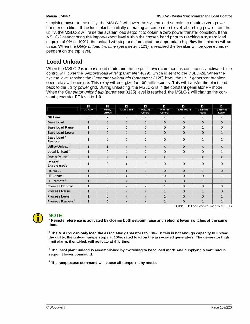
Manual 37444C MSLC-2 - Master Synchronizer and Load Control
© Woodward Page 157/220
supplying power to the utility, the MSLC-2 will lower the system load setpoint to obtain a zero power transfer condition. If the local plant is initially operating at some import level, absorbing power from the utility, the MSLC-2 will raise the system load setpoint to obtain a zero power transfer condition. If the MSLC-2 cannot bring the import/export level within the chosen band prior to reaching a system load setpoint of 0% or 100%, the unload will stop and if enabled the appropriate high/low limit alarms will ac-tivate. When the Utility unload trip time (parameter 3123) is reached the breaker will be opened inde-pendent on the trip level.
Local Unload When the MSLC-2 is in base load mode and the setpoint lower command is continuously activated, the control will lower the Setpoint load level (parameter 4629), which is sent to the DSLC-2s. When the system level reaches the Generator unload trip (parameter 3125) level, the Lcl. / generator breaker open relay will energize. This relay will energize for 400 milliseconds. This will transfer the plant load back to the utility power grid. During unloading, the MSLC-2 is in the constant generator PF mode. When the Generator unload trip (parameter 3125) level is reached, the MSLC-2 will change the con-stant generator PF level to 1.0.
DI
CB AUX
DI Utility
Unload
DI Base Load
DI Imp/Exp Control
DI Process Control
DI Ramp Pause
DI Setpoint
Raise
DI Setpoint Lower
Off Line 0 x x x x x x x
Base Load 1 0 1 0 0 0 0 0
Base Load Raise 1 0 1 0 0 0 1 0
Base Load Lower 1 0 1 0 0 0 0 1
Base Load 1
Remote 1 0 1 0 0 0 1 1
Utility Unload 2 1 1 x x x 0 x x
Local Unload 3 1 0 1 0 0 0 0 1
Ramp Pause 4 1 x x x x 1 x x
Import/ Export mode
1 0 x 1 0 0 0 0
I/E Raise 1 0 x 1 0 0 1 0
I/E Lower 1 0 x 1 0 0 0 1
I/E Remote 1 1 0 x 1 0 0 1 1
Process Control 1 0 x x 1 0 0 0
Process Raise 1 0 x x 1 0 1 0
Process Lower 1 0 x x 1 0 0 1
Process Remote 1 1 0 x x 1 0 1 1
Table 5-1: Load control modes MSLC-2
NOTE 1 Remote reference is activated by closing both setpoint raise and setpoint lower switches at the same
time. 2 The MSLC-2 can only load the associated generators to 100%. If this is not enough capacity to unload
the utility, the unload ramps stops at 100% rated load on the associated generators. The generator high limit alarm, if enabled, will activate at this time. 3 The local plant unload is accomplished by switching to base load mode and supplying a continuous
setpoint lower command. 4 The ramp pause command will pause all ramps in any mode.
Manual 37444C MSLC-2 - Master Synchronizer and Load Control
Page 158/220 © Woodward
Chapter 6. Var/Power Factor Control Description
Introduction
≡≡≡≡≡≡≡≡≡≡≡≡≡≡≡≡≡≡≡≡≡≡≡≡≡ The MSLC-2 offers 3 modes of reactive power control. Var or power factor modes will control the reac-tive power at the utility breaker while constant generator PF control will provide a power factor setpoint to all DSLC-2 controls on the system. When a utility unload command is issued, the control automatically shifts from var control to power fac-tor control in order to ensure a minimum amount of current flow across the utility tie when it is opened. It is important to note that, as with the real load functions, the var/PF control in the MSLC-2 controls only those DSLC-2 controls which are in isochronous load sharing. Any DSLC-2 controls which are in base load mode will control the reactive power on their associated generators in accordance with their own internal reference and chosen mode of var/PF control.
Constant Generator Power Factor
≡≡≡≡≡≡≡≡≡≡≡≡≡≡≡≡≡≡≡≡≡≡≡≡≡ The MSLC-2 sets the power factor reference of the generators according to the value chosen by:
Base Configuration: VAR PF control mode (parameter 7558) configured to “Constant Gener-ator PF” and reference value Constant gen. PF reference (parameter 5621).
ToolKit: Changing the Constant gen. PF reference (parameter 5621) in ToolKit will change the reference value being controlled.
Adaptation: With the settings of the base configuration the constant gen PF reference can be influenced by voltage raise and voltage lower commands.
Remote: With the settings of the base configuration the Constant gen PF reference (parame-ter 5621) can be influenced by an analog signal (“Reactive Load Input”). The voltage raise and voltage lower signal must be energized simultaneously.
Interface: With the settings of the base configuration the Constant gen PF reference (parame-ter 5621) can be influenced by interface, when the configuration VAR control setpoint source (parameter 7635) is set to “Interface”.
Control: The DSLC-2s PID var control will affect the stability of the power factor control.

Manual 37444C MSLC-2 - Master Synchronizer and Load Control
© Woodward Page 159/220
Power Factor Control
≡≡≡≡≡≡≡≡≡≡≡≡≡≡≡≡≡≡≡≡≡≡≡≡≡ The MSLC-2 adjusts the power factor references of the generators in order to maintain a chosen power factor level across the utility tie. The MSLC-2 sends a system reactive power percentage value to the DSLC-2s. Following procedures are possible:
Base Configuration: VAR PF control mode (parameter 7558) configured to “PF Control” and Power factor reference (parameter 5620) is configured.
ToolKit: Changing the Power factor reference (parameter 5620) in ToolKit will change the ref-erence value being controlled.
Remote: With the settings of the base configuration the Power factor reference (parameter 5620) at the MSLC-2 can be influenced by an analog signal (“Reactive Load Input”). The volt-age raise and voltage lower signal must be energized simultaneously.
Interface: With the settings of the base configuration the Power factor reference (parameter 5620) at the MSLC-2 can be influenced by interface, when the configuration VAR control setpoint source (parameter 7635) is set to “Interface”.
Control: The PID var control setting in the MSLC-2, Menu 4 will affect the stability of the pow-er factor control.
Var Control
≡≡≡≡≡≡≡≡≡≡≡≡≡≡≡≡≡≡≡≡≡≡≡≡≡ The MSLC-2 adjusts the power factor reference of the generators in order to maintain a chosen var level across the utility tie. The MSLC-2 sends a system reactive power percentage value to the DSLC-2s. The unit allows only one basic setting:
Base Configuration: VAR PF control mode (parameter 7558) configured to “VAR Control” and KVAR reference (parameter 7723) is configured.
ToolKit: Changing the KVAR reference (parameter 7723) in ToolKit will change the reference value being controlled.
Control: The PID var control settings in the MSLC-2, Menu 4, will affect the stability of the var control.

Manual 37444C MSLC-2 - Master Synchronizer and Load Control
Page 160/220 © Woodward
Chapter 7. Process Control Description
Introduction
≡≡≡≡≡≡≡≡≡≡≡≡≡≡≡≡≡≡≡≡≡≡≡≡≡ The process control function of the MSLC-2 will control any process where the controlled parameter is determined by the load on the local generators and the controlled parameter can be monitored as as an analog input signal (process input). The control compares the input signal to the process reference setpoint, or the remote reference if used and adjusts the local generator loading to maintain the desired setpoint.
NOTE The MSLC-2 system load command is obeyed only by the associated DSLC-2 controls which are in isochronous load sharing. DSLC-2s in Base load or process control mode will ignore the MSLC-2 load command signal and maintain its set load reference. The DSLC-2s Load Control mode (parameter 4603) will display Base load mode when being controlled by a MSLC-2.
Description
≡≡≡≡≡≡≡≡≡≡≡≡≡≡≡≡≡≡≡≡≡≡≡≡≡ Figure 7-1 shows a block diagram of the process control function. The process control mode is select-ed when the “Process Control” and “CB Aux” switch contacts are closed. The process input signal is compared with the process reference, which may be either the internal Process reference (parameter 4605) or the analog remote process reference input (Configurable in Menu 6). In process control mode, the “Load Raise” and “Load Lower” contact inputs operate on the process control reference. When the internal reference is used, the “Load Raise” and “Load Lower” contacts raise and lower the process reference based on the internal Process reference (parameter 4605). The analog remote reference in-put becomes active on the process reference, when both the “Load Raise” and “Load Lower” contacts are closed. Each time a new process control begins, the first error signal is checked. If the process error signal is higher than 5% or lower than -5% the generator load is guided over a ramp function to leveling the er-ror signal. This shall be a relatively smooth process. When the error signal resides within +/-5% the Process PID function becomes active. The process PID function also becomes active, if the ramp func-tion has reached the minimum or the maximum gen load level (0 to 100%). If the process PID is one time activated, it remains active until the process control is switched off or the CB gets open. When the process control is enabled, the PID controller operates in cascade with the load control. The output of the controller is a generator load reference within the range 0 to 100% rated power to prevent overload or reverse power on the generator. The load setting signal is output from the load control to the speed control to set control at the required load to maintain the desired process level. An additional feature of the process control is the adjustable process input signal filter. The adjustable Process filter, Menu 3 (parameter 4509) allows reducing bandwidth when controlling a noisy process such as experi-enced in digester gas fuel applications. The process control function is configurable for direct and in-verse action. Direct process control is where the sensed input signal increases as the load increases (such as where the sensed input is exhaust pressure or export power). An inverse action control is where the sensed input signal decreases as the load increases (such as when controlling import power where the import power will decrease as the generating system picks up more of the local load). The process error is the difference between process signal input and process reference. The controller in the MSLC-2 regulates the percentage values. For a better understanding the engineering unit can be
Manual 37444C MSLC-2 - Master Synchronizer and Load Control
© Woodward Page 161/220
displayed according to the percentage value. Therefore the scaling of the percentage value is to make with according engineering units (parameter 7732, parameter 7733 and parameter 7734). The units are then displayed in field parameter 7726 and in field parameter 7727 in Menu 6 or the Homepage. The Process signal input (parameter 10151) and the Remote reference input (parameter 10117) is dis-played in Menu 6 in%. The resulting Process reference (parameter 4605) and the resulting Process signal input (parameter 4600) is displayed in the Homepage in%.
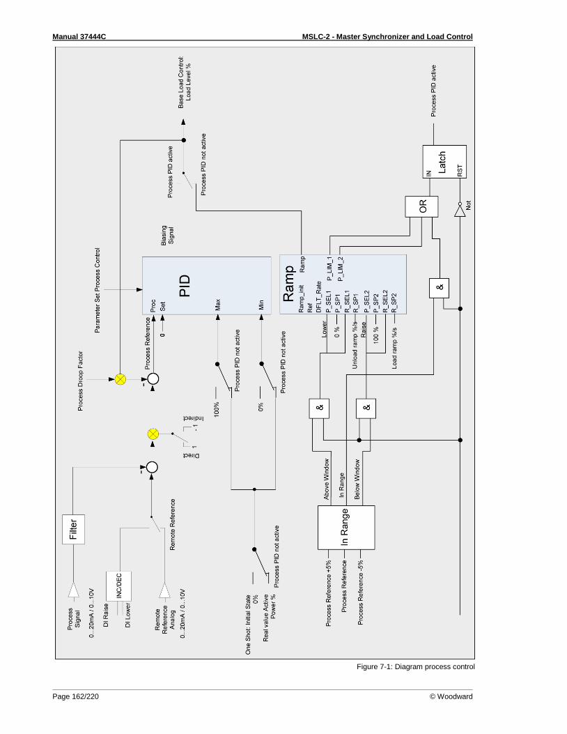
Manual 37444C MSLC-2 - Master Synchronizer and Load Control
Page 162/220 © Woodward
Figure 7-1: Diagram process control

Manual 37444C MSLC-2 - Master Synchronizer and Load Control
© Woodward Page 163/220
Chapter 8. Network / System Description
Introduction
≡≡≡≡≡≡≡≡≡≡≡≡≡≡≡≡≡≡≡≡≡≡≡≡≡ The new DSLC-2 / MSLC-2 system provides within one network following features:
• The maximum number of DSLC-2s (Generator) can go up to 32. • The maximum number of MSLC-2s (Utility- or Tie-breaker) can go up to 16. • The maximum number of segments is 8.
The DSLC-2 still cares about the generator breaker and the MSLC-2 cares about utility breaker or a tie-breaker. The DSLC-2 and MSLC-2 can reside at different segments. A segment is defined as the smallest undividable bar in a system. Segment connectors inform the DSLC-2s and MSLC-2s which generators and utilities are connected. Through the segmenting the DSLC-2 / MSLC-2 can recognize all the time with which other units they are interconnected. So the DSLC-2s in the same segment are load share together or doing an independent load control. The MSLC-2s can be configured to utility breaker mode or to tie-breaker mode. In each case it is only allowed to have one MSLC-2 in one segment running as master control. A MSLC-2 gets a master con-trol when base load control, export/import control or process control is activated. If multiple MSLC-2s are in the same segment, the control with the lowest device number will be master.
Description
≡≡≡≡≡≡≡≡≡≡≡≡≡≡≡≡≡≡≡≡≡≡≡≡≡ Beside the upper described restrictions there are existing additional rules for the successful operation of the DSLC-2 / MSLC-2 system. Please read this rules and compare it with your planned application.
• The segment numbers have to follow a line, which can finally be closed to a ring. A segment branch is not allowed.
• There can be placed several MSLC-2 in one segment, but only one MSLC-2 can run as Master control.
• The generator is not counted as a segment. • The utility is not counted as a segment.
The intention of the following application examples is to provide a better understanding of the philoso-phy of segmenting:
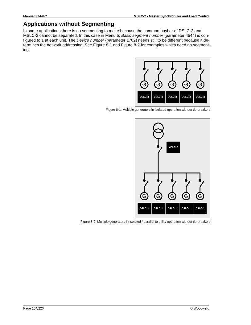
Manual 37444C MSLC-2 - Master Synchronizer and Load Control
Page 164/220 © Woodward
Applications without Segmenting In some applications there is no segmenting to make because the common busbar of DSLC-2 and MSLC-2 cannot be separated. In this case in Menu 5, Basic segment number (parameter 4544) is con-figured to 1 at each unit. The Device number (parameter 1702) needs still to be different because it de-termines the network addressing. See Figure 8-1 and Figure 8-2 for examples which need no segment-ing.
Figure 8-1: Multiple generators in isolated operation without tie-breakers
Figure 8-2: Multiple generators in isolated / parallel to utility operation without tie-breakers
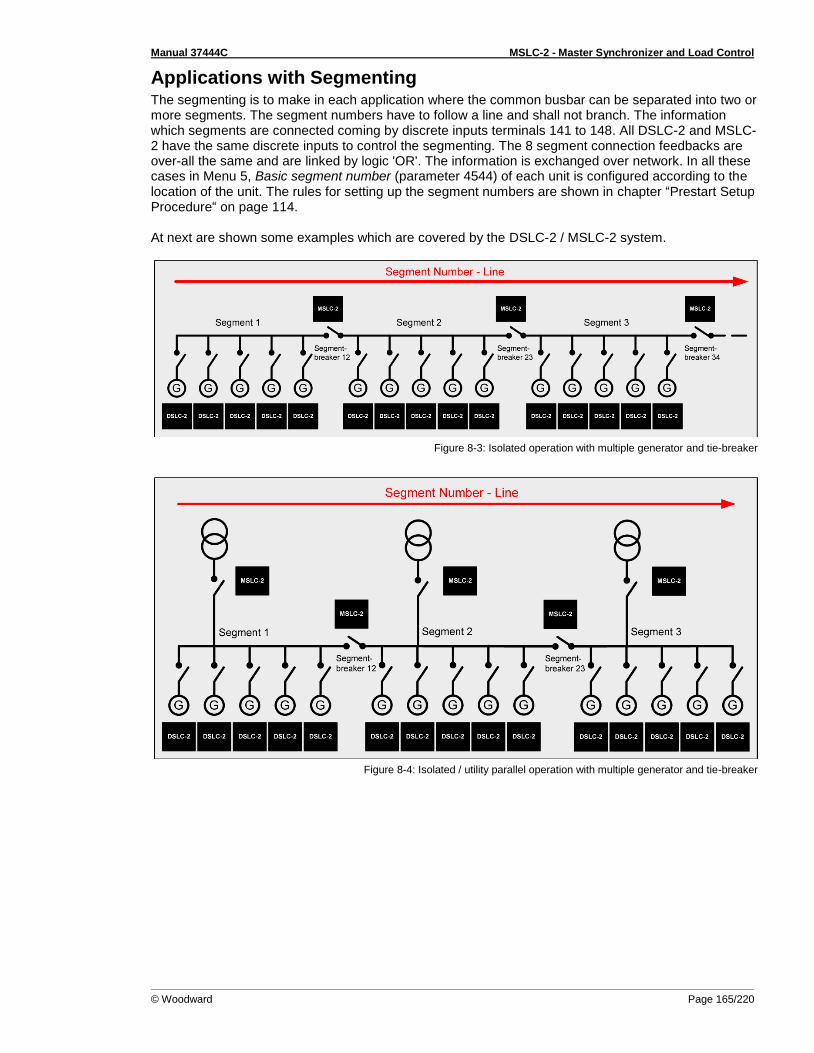
Manual 37444C MSLC-2 - Master Synchronizer and Load Control
© Woodward Page 165/220
Applications with Segmenting The segmenting is to make in each application where the common busbar can be separated into two or more segments. The segment numbers have to follow a line and shall not branch. The information which segments are connected coming by discrete inputs terminals 141 to 148. All DSLC-2 and MSLC-2 have the same discrete inputs to control the segmenting. The 8 segment connection feedbacks are over-all the same and are linked by logic 'OR'. The information is exchanged over network. In all these cases in Menu 5, Basic segment number (parameter 4544) of each unit is configured according to the location of the unit. The rules for setting up the segment numbers are shown in chapter “Prestart Setup Procedure“ on page 114. At next are shown some examples which are covered by the DSLC-2 / MSLC-2 system.
Figure 8-3: Isolated operation with multiple generator and tie-breaker
Figure 8-4: Isolated / utility parallel operation with multiple generator and tie-breaker
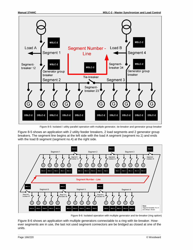
Manual 37444C MSLC-2 - Master Synchronizer and Load Control
Page 166/220 © Woodward
Figure 8-5: Isolated / utility parallel operation with multiple generator, tie-breaker and generator group breaker
Figure 8-5 shows an application with 2 utility feeder breakers, 2 load segments and 2 generator group breakers. The segment line begins at the left side with the load A segment (segment no.1) and ends with the load B segment (segment no.4) at the right side.
Figure 8-6: Isolated operation with multiple generator and tie-breaker (ring option)
Figure 8-6 shows an application with multiple generators connectable to a ring with tie-breaker. How-ever segments are in use, the last not used segment connectors are be bridged as closed at one of the units.
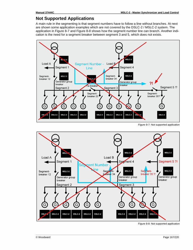
Manual 37444C MSLC-2 - Master Synchronizer and Load Control
© Woodward Page 167/220
Not Supported Applications A main rule in the segmenting is that segment numbers have to follow a line without branches. At next are shown some application examples which are not covered by the DSLC-2 / MSLC-2 system. The application in Figure 8-7 and Figure 8-8 shows how the segment number line can branch. Another indi-cation is the need for a segment breaker between segment 3 and 5, which does not exists.
Figure 8-7: Not supported application
Figure 8-8: Not supported application

Manual 37444C MSLC-2 - Master Synchronizer and Load Control
Page 168/220 © Woodward
Remote Control by PLC
≡≡≡≡≡≡≡≡≡≡≡≡≡≡≡≡≡≡≡≡≡≡≡≡≡ The DSLC-2 / MSLC-2 system offers two channels of Ethernet and one channel serial interface RS-485. Ethernet channel A and channel B are the dedicated communication bus for the Woodward own UDP message system, which is used to exchange information between all units in the network. In Menu 5.1 the “Network A –UDP TCP/IP address” (parameter 5330) has to be configured for. Each unit gets its own address usually related to the own Device number (parameter 1702). Ethernet channel A and Ethernet channel B can be used for visualization and remote control of all units. The protocol here used is Modbus/TCP. In Menu 5.1 the “Network B – Modbus TCP/IP address” (parameter 5430) has to be configured for. Each unit gets its own address usually related to the own Device number (parameter 1702). Additionally the unit offers a serial RS-485 connection for visualization and remote control. The visuali-zation can be done simultaneously by Ethernet and RS-485. In Menu 5.1 the “Modbus Serial Interface 2 Modbus slave ID” (parameter 3188) has to be configured for. Each unit gets its own slave ID usually related to the own Device number (parameter 1702). The remote control has to be configured for either RS-485 or Ethernet. Furthermore the DSLC-2 / MSLC-2 allow distribute functions to discrete inputs and to protocol bits.
Interface Connection via RS-485 with Modbus Protocol The DSLC-2 / MSLC-2 system provides a RS-485 Modbus connection. Each unit gets an own Modbus slave address. The DSLC-2 as the MSLC-2 allows to configure each parameter or to inform about each measurement value and binary information. For visualization the unit offers a special mapped Modbus table with all important values refer to “Data Protocol 5200“ on page 196.
Figure 8-9: Visualization and remote control by PLC via RS-485 interface
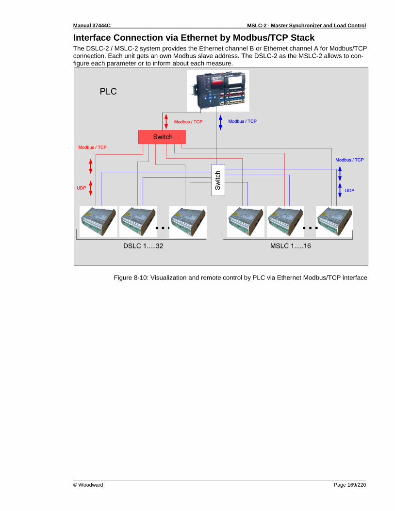
Manual 37444C MSLC-2 - Master Synchronizer and Load Control
© Woodward Page 169/220
Interface Connection via Ethernet by Modbus/TCP Stack The DSLC-2 / MSLC-2 system provides the Ethernet channel B or Ethernet channel A for Modbus/TCP connection. Each unit gets an own Modbus slave address. The DSLC-2 as the MSLC-2 allows to con-figure each parameter or to inform about each measure.
PLC
Modbus / TCP
DSLC 1.....32
...MSLC 1.....16
...
Modbus / TCP
UDP
Switch
UDP
Modbus / TCP
Modbus / TCP
Sw
itch
Figure 8-10: Visualization and remote control by PLC via Ethernet Modbus/TCP interface
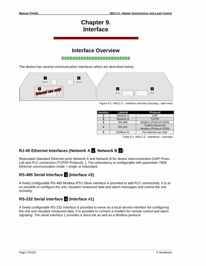
Manual 37444C MSLC-2 - Master Synchronizer and Load Control
Page 170/220 © Woodward
Chapter 9. Interface
Interface Overview
≡≡≡≡≡≡≡≡≡≡≡≡≡≡≡≡≡≡≡≡≡≡≡≡≡ The device has several communication interfaces which are described below.
Figure 9-1: MSLC-2 - interface overview (housing - side view)
Number Labeled Protocol
1 Network A UDP
2 Network B TCP/IP
3 RS-485 Modbus (Protocol 5200)
4 RS-232 ToolKit (ServLink)
Modbus (Protocol 5200)
5 CANbus #1 For internal use only!
Table 9-1: MSLC-2 - Interfaces - overview
RJ-45 Ethernet Interfaces (Network A 1 , Network B 2 ) Redundant Standard Ethernet ports Network A and Network B for device interconnection (UDP Proto-col) and PLC connection (TCP/IP Protocol). ). The redundancy is configurable with parameter 7809 Ethernet communication mode = single or redundant.
RS-485 Serial Interface 3 (Interface #2)
A freely configurable RS-485 Modbus RTU Slave interface is provided to add PLC connectivity. It is al-so possible to configure the unit, visualize measured data and alarm messages and control the unit remotely.
RS-232 Serial Interface 4 (Interface #1)
A freely configurable RS-232 interface is provided to serve as a local service interface for configuring the unit and visualize measured data. It is possible to connect a modem for remote control and alarm signaling. The serial interface 1 provides a ServLink as well as a Modbus protocol.
Manual 37444C MSLC-2 - Master Synchronizer and Load Control
© Woodward Page 171/220
Communication management
Redundant Bus topology In general: if a bus fails, it shall be switched automatically to the other bus and an alarm shall be acti-vated. Each unit in the network system is displayed in the overview screen. The status of each unit can be recognized. The display "Unit ID available" (see OVERVIEW PAGE screens) helps the operator to de-tect, where a defect unit or wire is located.
What happens if only Network A fails?
All functions are fully maintained. The alarm "7792 Network A error" is triggered on all devices. The device, which cannot successfully send data over the Network A, sets in addition the alarm "4615 Communication error network A". In the ToolKit overview diagram DSLC2 and MSLC2 it can be de-tected via the information "Unit ID available", which device is down.
What happens if only Network B fails?
All functions are fully maintained. The alarm "7793 Network B error" is triggered on all devices. The device, which cannot successfully send data over the Network B, sets in addition the alarm "7787 Communication error network B". In the ToolKit overview diagram DSLC2 and MSLC2 it can be de-tected via the information "Unit ID available", which device is down.
What happens if both Network A and Network B are down to one device?
The alarm "Missing member" is triggered on all devices. In addition, alarms, as described subsequently are issued.
What happens if both Network A and Network B fail?
The alarms "7792 Network A error" and "7793 Network B error" are triggered on each device. The de-vice, which no longer can successfully send data over the Network A and / or Network B, sets in addi-tion the alarms "4615 Communication error network A" and / or “7787 Communication error network B". In the ToolKit overview pages DSLC2 and MSLC2 it can be detected via the information "Unit ID avail-able", which device is down.
Single Bus topology In general: if a network (Network A) fails, it shall be switched automatically to droop if configured and an alarm shall be activated. Each unit in the network system is displayed in the overview screen. The status of each unit can be recognized. The display "Unit ID available" (see OVERVIEW PAGE screens and tables below) helps the operator to detect, where a defect unit or wire is located.
What happens if Network A fails
The alarm "4617 Missing member" is triggered on each device. The device, which can no longer suc-cessfully send data over the Network A, sets in addition the alarm "4615 Communication error network A”. In the overview diagram DSLC2 and MSLC2 it can be detected via the information "Unit ID availa-ble", which device is down.

Manual 37444C MSLC-2 - Master Synchronizer and Load Control
Page 172/220 © Woodward
Visualization of the Bus System
ToolKit Overview pages DSLC2 / MSLC2
The overview pages from DSLC2 and MSLC2 are showing the state of the networks in the field "Unit ID available" in the view of a single unit. The dedicated description is shown in the previous chapters.
ToolKit Homepage
In the ToolKit Home page the actual number of teached units is shown in a field. A red LED still indi-cates "Missing member alarm like it is in Release 1.
ToolKit - Status Control Monitoring of Alarms
On the page Menu 8, the following Alarms are displayed: • Communication error Network A • Communication error Network B • Network A Error • Network B Error • Devices not matched
Commissioning of the Communication Network System
Precondition:
All interfaces are wired.
The correct equipment configuration is installed.
All single overview pages (page 111ff) display the corresponding status. If not:
Check the configuration of the device
Check and repair wiring
Check and update configuration(s)
Go for System update parameter 7789 to teach the correct system status.
NOTE The system update process described below can be executed on each of the devices recognized under each other.
System update process The System update process can be started by
energizing DI 23 "System update" or
using the parameter 7789 System update in ToolKit or
sending the System update signal by communication interface (see page 179ff for details)
NOTE The DI 23 e.g., can be handled by a push button. The unit reacts on a rising edge.
With this command the according device sends a system update signal for 30 seconds to all connected devices on the network. During this time the DSLC / MSLC Ethernet network system will be updated on the current network constellation. Single Bus or redundant bus will be incorporated. During the system update process, the CPU OK LED on cover of the DSLC-2 is flashing. After this procedure all corresponding alarms should disappear and the correct number of participants is recognized, displayed, and stored in parameter 7791 Number of devices in system. In case Network A and/or Network B are not available the according alarms are (still) activated.

Manual 37444C MSLC-2 - Master Synchronizer and Load Control
© Woodward Page 173/220
Changing a device in a running system First it is to check whether there is not yet a "Missing member" alarm active on the Ethernet network. If this alarm is active the reason for this is to clarify first. Otherwise the system update procedure would fade out this alarm situation.
1. The operator sends a system update command to the whole system by DI23 “System update”. Then within the next 30 seconds he powers-off the particular device. After these 30 seconds the other controls are accepting the new constellation and monitor the network with one device lesser. No missing member alarm will occur!
2. The operator changes now the device and takes care that the communication network is not reconnected as long he has not configured the device correctly. If the device is configured cor-rectly, he can reconnect the network.
3. After repowering and reconnecting the device, the system will automatically report that the sys-tem is over determined (by this changed device). It requests a new system update through the information “Add device” in the overview page. After checking this, the operator executes a new system update command. The alarm will disappear, if all works correct. The missing de-vice monitor will take from now on this additional member into account.
Switching off a device in a running system (i.e. servicing the engine) First it is to check whether there is not yet a "Missing member" alarm active on the Ethernet network. If this alarm is active the reason for this is to clarify first. Otherwise the system update procedure would fade out this alarm situation.
1. The operator sends a system update command to the whole system by DI23 “System update”. Then within the next 30 seconds he powers-off the particular device. After these 30 seconds the other controls are accepting the new constellation and monitor the network with one device lesser. No missing member alarm will occur!
Adding a device to a running system (i.e. Commissioning new Genset) First it is to check whether there is not yet a "Missing member" alarm active on the Ethernet network. If this alarm is active the reason for this is to clarify first. Otherwise the system update procedure would fade out this alarm situation.
After configuration, connecting and powering the device, the system will automatically report that the system is over determined. It requests a new system update through the information “Add device” in the overview page. After checking this, the operator executes a new system update command. The alarm will disappear, if all works correct. The missing device monitor will take from now on this addi-tional member into account.
Manual 37444C MSLC-2 - Master Synchronizer and Load Control
Page 174/220 © Woodward
Ethernet Load Sharing
≡≡≡≡≡≡≡≡≡≡≡≡≡≡≡≡≡≡≡≡≡≡≡≡≡
Multi-Master Principle It is important to know that the load share and load-dependent start/stop functionality is subject to a multi-master principle. This means that there is no dedicated master and slave function. Each MSLC-2 decides for itself how it has to behave. The benefit is that there is no master control, which may cause a complete loss of this functionality in case it fails. Each control is also responsible for controlling common breakers like a mains circuit or generator group breaker.
Load Share Monitoring The MSLC-2 provides the following monitoring function for load sharing:
Multi-Unit Missing Members
The multi-unit missing members monitoring function checks whether all participating units are available (sending data on the Ethernet line).
Switches
Please use a 10/100 Mbit/s Ethernet switch if more than two devices should be connected.
General Load Share Information The maximum number of participating DSLC-2 devices for load sharing is 32. The maximum number of MSLC-2 devices is 16. The following parameters affect the bus load:
• Baud rate • Transfer rate of load share messages • Visualization
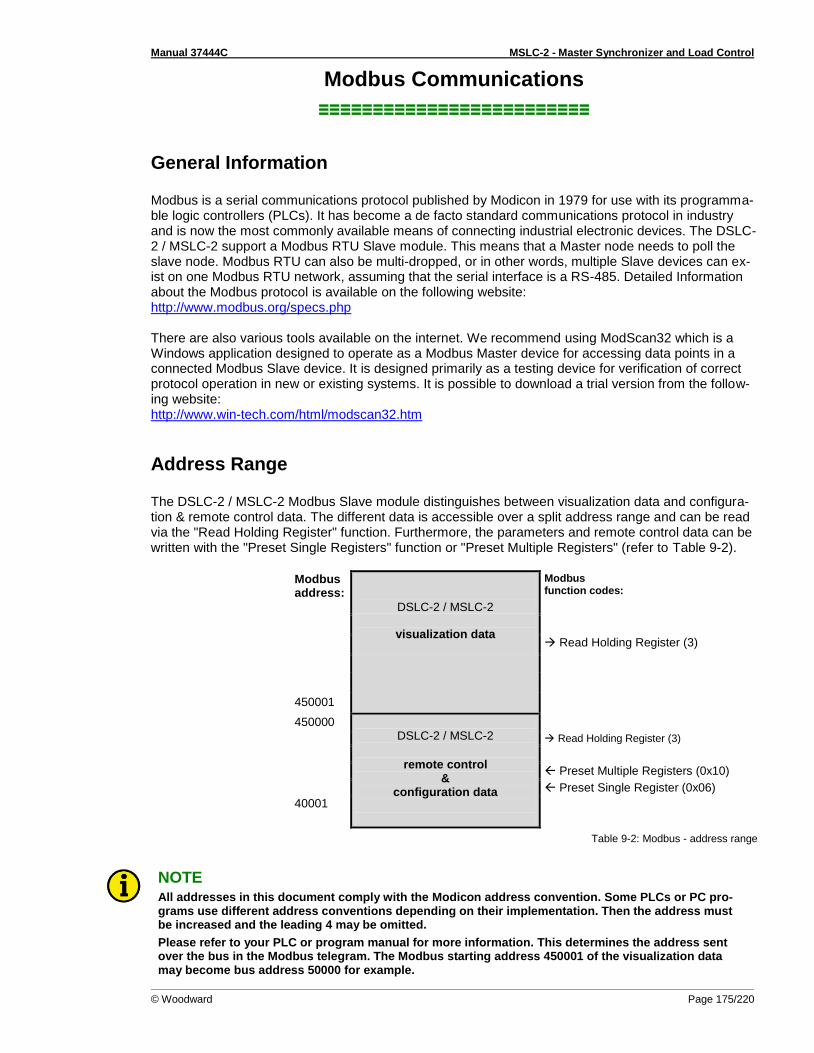
Manual 37444C MSLC-2 - Master Synchronizer and Load Control
© Woodward Page 175/220
Modbus Communications
≡≡≡≡≡≡≡≡≡≡≡≡≡≡≡≡≡≡≡≡≡≡≡≡≡
General Information Modbus is a serial communications protocol published by Modicon in 1979 for use with its programma-ble logic controllers (PLCs). It has become a de facto standard communications protocol in industry and is now the most commonly available means of connecting industrial electronic devices. The DSLC-2 / MSLC-2 support a Modbus RTU Slave module. This means that a Master node needs to poll the slave node. Modbus RTU can also be multi-dropped, or in other words, multiple Slave devices can ex-ist on one Modbus RTU network, assuming that the serial interface is a RS-485. Detailed Information about the Modbus protocol is available on the following website: http://www.modbus.org/specs.php There are also various tools available on the internet. We recommend using ModScan32 which is a Windows application designed to operate as a Modbus Master device for accessing data points in a connected Modbus Slave device. It is designed primarily as a testing device for verification of correct protocol operation in new or existing systems. It is possible to download a trial version from the follow-ing website: http://www.win-tech.com/html/modscan32.htm
Address Range The DSLC-2 / MSLC-2 Modbus Slave module distinguishes between visualization data and configura-tion & remote control data. The different data is accessible over a split address range and can be read via the "Read Holding Register" function. Furthermore, the parameters and remote control data can be written with the "Preset Single Registers" function or "Preset Multiple Registers" (refer to Table 9-2).
Modbus address:
DSLC-2 / MSLC-2
visualization data
Modbus function codes:
Read Holding Register (3)
450001
450000 DSLC-2 / MSLC-2
remote control
& configuration data
Read Holding Register (3)
Preset Multiple Registers (0x10)
Preset Single Register (0x06)
40001
Table 9-2: Modbus - address range
NOTE All addresses in this document comply with the Modicon address convention. Some PLCs or PC pro-grams use different address conventions depending on their implementation. Then the address must be increased and the leading 4 may be omitted.
Please refer to your PLC or program manual for more information. This determines the address sent over the bus in the Modbus telegram. The Modbus starting address 450001 of the visualization data may become bus address 50000 for example.

Manual 37444C MSLC-2 - Master Synchronizer and Load Control
Page 176/220 © Woodward
Visualization The visualization over Modbus is provided in a very fast data protocol where important system data like alarm states, AC measurement data, switch states and various other information may be polled. Ac-cording to the DSLC-2 / MSCL-2 Modbus addressing range, the visualization protocol can be reached on addresses starting at 450001. On this address range it is possible to do block reads from 1 up to 128 Modbus registers at a time.
Modbus Read Addresses
Description Multiplier Units
450001 Protocol-ID, always 5200 --
450002 Scaling power --
............ ......... ..... .....
............ ......... ..... .....
............ ......... ..... .....
............ ......... ..... .....
450171 Remote load reference input
0.1 kW
Table 9-3: Modbus - address range block read
NOTE Table 9-3 is only an excerpt of the data protocol. It conforms to the data protocol 5200 that is also used by Ethernet. Refer to “Data Protocol 5200“ on page 196 for the complete protocol.
The following ModScan32 screenshot shows the configurations made to read the visualization protocol with a block read of 128 registers.
Figure 9-2: Modbus - visualization configurations
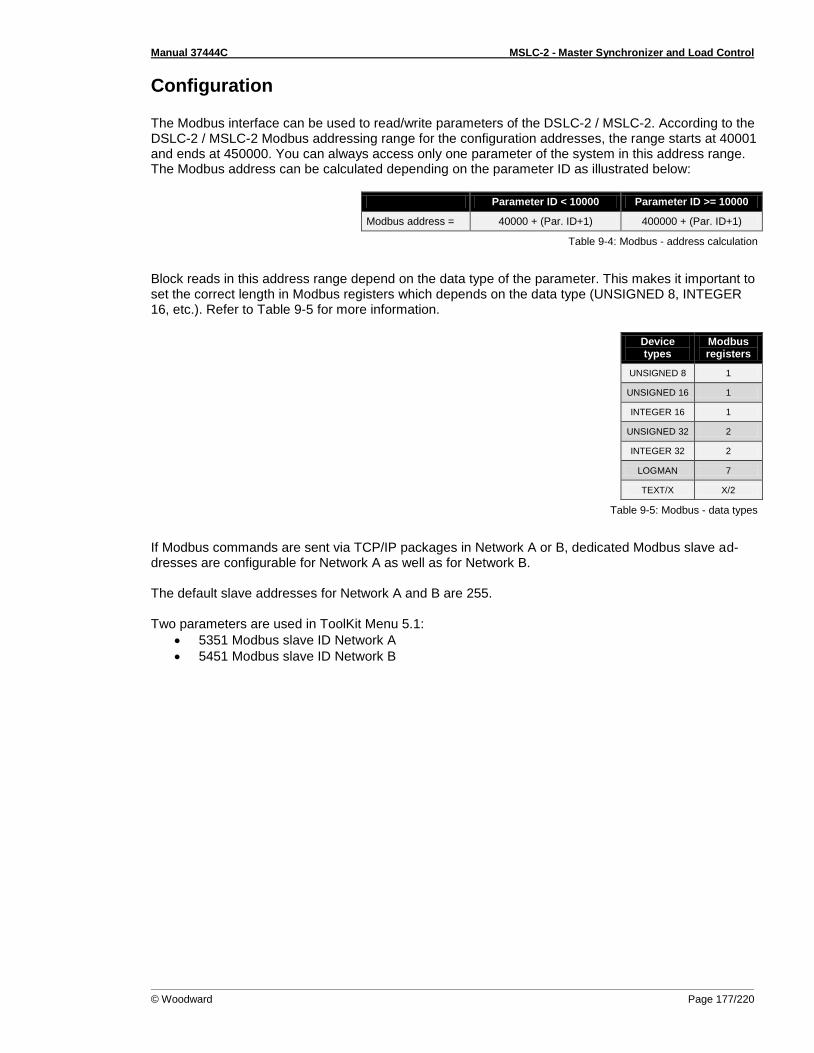
Manual 37444C MSLC-2 - Master Synchronizer and Load Control
© Woodward Page 177/220
Configuration The Modbus interface can be used to read/write parameters of the DSLC-2 / MSLC-2. According to the DSLC-2 / MSLC-2 Modbus addressing range for the configuration addresses, the range starts at 40001 and ends at 450000. You can always access only one parameter of the system in this address range. The Modbus address can be calculated depending on the parameter ID as illustrated below:
Parameter ID < 10000 Parameter ID >= 10000
Modbus address = 40000 + (Par. ID+1) 400000 + (Par. ID+1)
Table 9-4: Modbus - address calculation
Block reads in this address range depend on the data type of the parameter. This makes it important to set the correct length in Modbus registers which depends on the data type (UNSIGNED 8, INTEGER 16, etc.). Refer to Table 9-5 for more information.
Device types
Modbus registers
UNSIGNED 8 1
UNSIGNED 16 1
INTEGER 16 1
UNSIGNED 32 2
INTEGER 32 2
LOGMAN 7
TEXT/X X/2
Table 9-5: Modbus - data types
If Modbus commands are sent via TCP/IP packages in Network A or B, dedicated Modbus slave ad-dresses are configurable for Network A as well as for Network B. The default slave addresses for Network A and B are 255. Two parameters are used in ToolKit Menu 5.1:
5351 Modbus slave ID Network A
5451 Modbus slave ID Network B

Manual 37444C MSLC-2 - Master Synchronizer and Load Control
Page 178/220 © Woodward
MSLC-2 Interface Remote Control For a remote setting of the control setpoints, it is necessary to use the interface setpoints instead of the internal setpoints. No password is required to write this value. All other setpoint sources are configured accordingly. Control orders can be sent via Ethernet (Modbus/TCP) or RS-485 Modbus RTU.
Sending Setpoints Over Interface
Some setpoints can be sent over the communication interface.
ID Parameter CL Setting range Default Description
7642 Active power setpoint for import/ export control
- 1 kW to 999999,9 kW
- Setpoint for the active power control. The setpoint is a long integer 32 to provide a wide range from 1 kW to 999999.9 kW. Negative values are not allowed.
Example: 1000 kW = 1000 = 3E8Hex
Note: This setpoint will be only accepted when the parameter Load control setpoint source (parameter 7634) is configured to “Interface”.
7640 Setpoint power factor import/ export
- -500 to 1000 to 500
- The power factor is set as a value (integer 16) between -500to 1000 to 500. A negative value is capacitive, a positive value is in-
ductive, 1000 = cos 1. Other values are not accepted by the unit.
Example:
cos = c0.71 cap. -710 FD3AHex
cos = 1.00 1000 03E8Hex
cos = i 0.71 ind. 710 02C6Hex
Note: This setpoint will be only accepted when the parameter VAR control setpoint source (parameter 7635) is configured to “In-terface”.
7641 Frequency Setpoint
0 to 7000 1/100 Hz
Setpoint Generator Frequency Control [Hz*100]
Example:
50.00Hz = 5000 = 1388Hex
Note: This setpoint will be only accepted when the parameter Freq. control setpoint source (parameter 7783) is configured to “Interface”.
7780 Voltage Setpoint
50 to 650000 V Voltage Setpoint for voltage control [V]
Example:
400V = 400 = 190Hex
10000V = 10000 = 2710Hex
Note: This setpoint will be only accepted when the parameter
Voltage control setpoint source (parameter 7784) is configured to
“Interface”.
7785 Basic Seg-ment number
1 to 8 Basic segment number
Example:
Range:1 to 8
Note: The Basic segment number will be only accepted when the
parameter Basic segment number source (parameter 7786) is
configured to “Interface”.
Table 9-6: Modbus – sending setpoints over interface
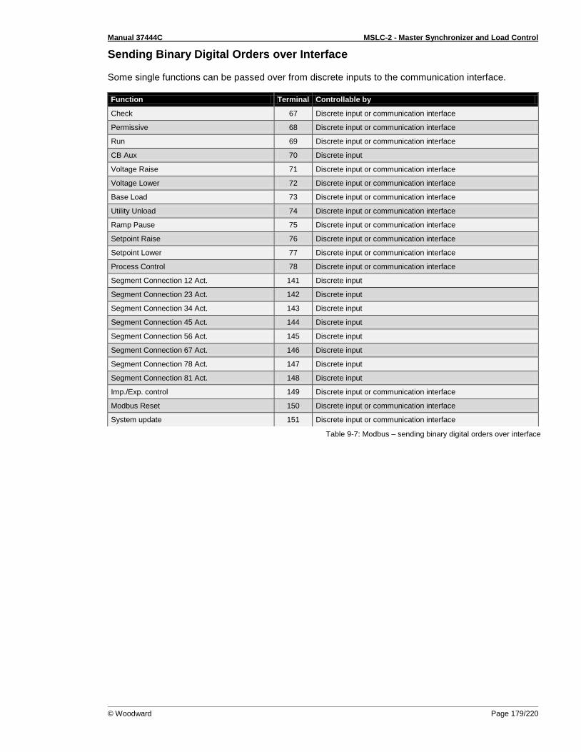
Manual 37444C MSLC-2 - Master Synchronizer and Load Control
© Woodward Page 179/220
Sending Binary Digital Orders over Interface Some single functions can be passed over from discrete inputs to the communication interface.
Table 9-7: Modbus – sending binary digital orders over interface
Function Terminal Controllable by
Check 67 Discrete input or communication interface
Permissive 68 Discrete input or communication interface
Run 69 Discrete input or communication interface
CB Aux 70 Discrete input
Voltage Raise 71 Discrete input or communication interface
Voltage Lower 72 Discrete input or communication interface
Base Load 73 Discrete input or communication interface
Utility Unload 74 Discrete input or communication interface
Ramp Pause 75 Discrete input or communication interface
Setpoint Raise 76 Discrete input or communication interface
Setpoint Lower 77 Discrete input or communication interface
Process Control 78 Discrete input or communication interface
Segment Connection 12 Act. 141 Discrete input
Segment Connection 23 Act. 142 Discrete input
Segment Connection 34 Act. 143 Discrete input
Segment Connection 45 Act. 144 Discrete input
Segment Connection 56 Act. 145 Discrete input
Segment Connection 67 Act. 146 Discrete input
Segment Connection 78 Act. 147 Discrete input
Segment Connection 81 Act. 148 Discrete input
Imp./Exp. control 149 Discrete input or communication interface
Modbus Reset 150 Discrete input or communication interface
System update 151 Discrete input or communication interface
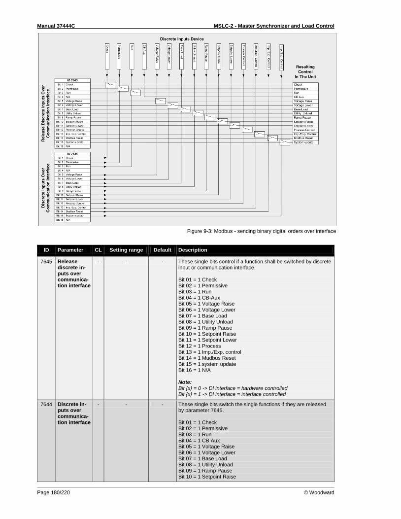
Manual 37444C MSLC-2 - Master Synchronizer and Load Control
Page 180/220 © Woodward
Figure 9-3: Modbus - sending binary digital orders over interface
ID Parameter CL Setting range Default Description
7645 Release discrete in-puts over communica-tion interface
- - - These single bits control if a function shall be switched by discrete input or communication interface. Bit 01 = 1 Check Bit 02 = 1 Permissive Bit 03 = 1 Run Bit 04 = 1 CB-Aux Bit 05 = 1 Voltage Raise Bit 06 = 1 Voltage Lower Bit 07 = 1 Base Load Bit 08 = 1 Utility Unload Bit 09 = 1 Ramp Pause Bit 10 = 1 Setpoint Raise Bit 11 = 1 Setpoint Lower Bit 12 = 1 Process Bit 13 = 1 Imp./Exp. control Bit 14 = 1 Mudbus Reset Bit 15 = 1 system update Bit 16 = 1 N/A Note: Bit x = 0 -> DI interface = hardware controlled Bit x = 1 -> DI interface = interface controlled
7644 Discrete in-puts over communica-tion interface
- - - These single bits switch the single functions if they are released by parameter 7645. Bit 01 = 1 Check Bit 02 = 1 Permissive Bit 03 = 1 Run Bit 04 = 1 CB Aux Bit 05 = 1 Voltage Raise Bit 06 = 1 Voltage Lower Bit 07 = 1 Base Load Bit 08 = 1 Utility Unload Bit 09 = 1 Ramp Pause Bit 10 = 1 Setpoint Raise
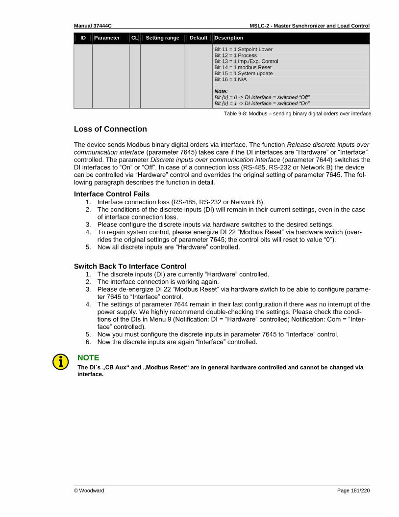
Manual 37444C MSLC-2 - Master Synchronizer and Load Control
© Woodward Page 181/220
ID Parameter CL Setting range Default Description
Bit 11 = 1 Setpoint Lower Bit 12 = 1 Process Bit 13 = 1 Imp./Exp. Control Bit 14 = 1 modbus Reset Bit 15 = 1 System update Bit 16 = 1 N/A Note: Bit x = 0 -> DI interface = switched “Off” Bit x = 1 -> DI interface = switched “On”
Table 9-8: Modbus – sending binary digital orders over interface
Loss of Connection The device sends Modbus binary digital orders via interface. The function Release discrete inputs over communication interface (parameter 7645) takes care if the DI interfaces are “Hardware” or “Interface” controlled. The parameter Discrete inputs over communication interface (parameter 7644) switches the DI interfaces to “On” or “Off”. In case of a connection loss (RS-485, RS-232 or Network B) the device can be controlled via “Hardware” control and overrides the original setting of parameter 7645. The fol-lowing paragraph describes the function in detail.
Interface Control Fails 1. Interface connection loss (RS-485, RS-232 or Network B). 2. The conditions of the discrete inputs (DI) will remain in their current settings, even in the case
of interface connection loss. 3. Please configure the discrete inputs via hardware switches to the desired settings. 4. To regain system control, please energize DI 22 “Modbus Reset” via hardware switch (over-
rides the original settings of parameter 7645; the control bits will reset to value “0”). 5. Now all discrete inputs are “Hardware” controlled.
Switch Back To Interface Control 1. The discrete inputs (DI) are currently “Hardware” controlled. 2. The interface connection is working again. 3. Please de-energize DI 22 “Modbus Reset” via hardware switch to be able to configure parame-
ter 7645 to “Interface” control. 4. The settings of parameter 7644 remain in their last configuration if there was no interrupt of the
power supply. We highly recommend double-checking the settings. Please check the condi-tions of the DIs in Menu 9 (Notification: DI = “Hardware” controlled; Notification: Com = “Inter-face” controlled).
5. Now you must configure the discrete inputs in parameter 7645 to “Interface” control. 6. Now the discrete inputs are again “Interface” controlled.
NOTE The DI´s „CB Aux“ and „Modbus Reset“ are in general hardware controlled and cannot be changed via interface.
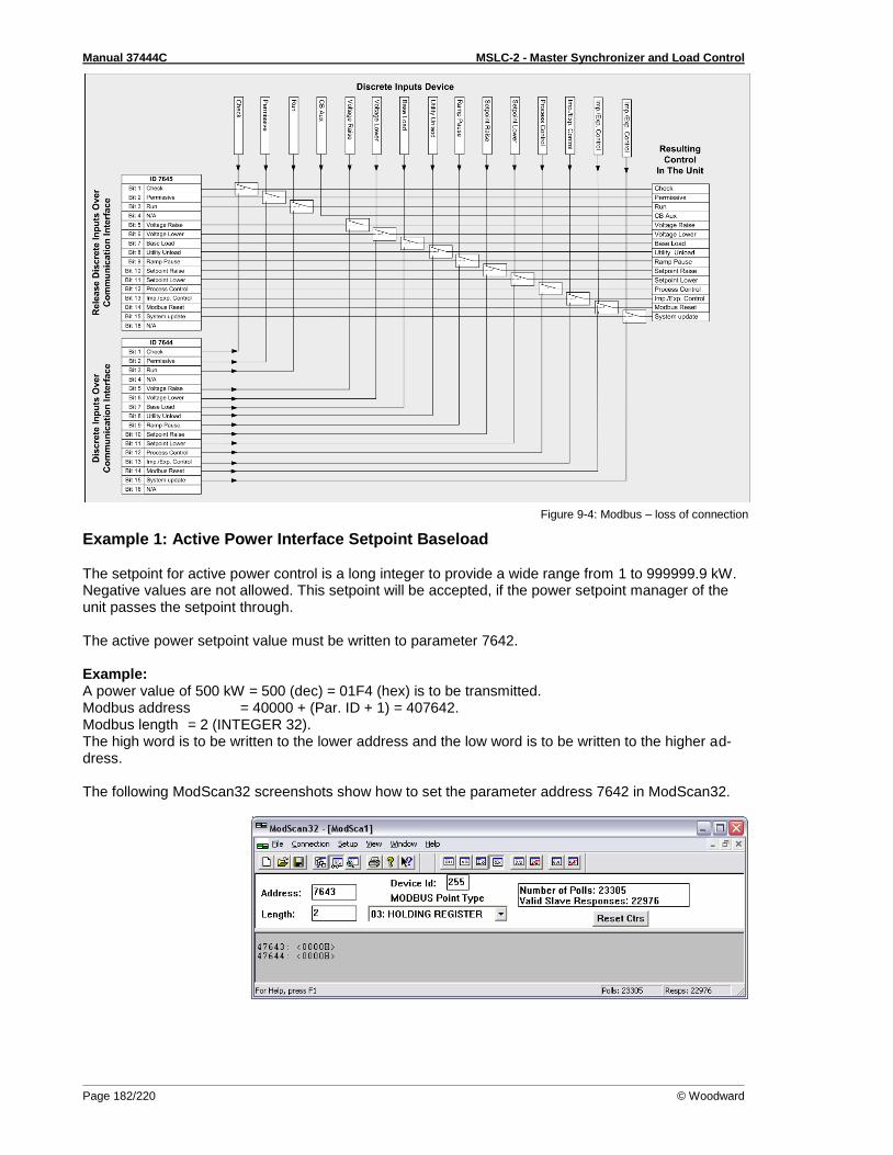
Manual 37444C MSLC-2 - Master Synchronizer and Load Control
Page 182/220 © Woodward
Figure 9-4: Modbus – loss of connection
Example 1: Active Power Interface Setpoint Baseload The setpoint for active power control is a long integer to provide a wide range from 1 to 999999.9 kW. Negative values are not allowed. This setpoint will be accepted, if the power setpoint manager of the unit passes the setpoint through. The active power setpoint value must be written to parameter 7642. Example: A power value of 500 kW = 500 (dec) = 01F4 (hex) is to be transmitted. Modbus address = 40000 + (Par. ID + 1) = 407642. Modbus length = 2 (INTEGER 32). The high word is to be written to the lower address and the low word is to be written to the higher ad-dress. The following ModScan32 screenshots show how to set the parameter address 7642 in ModScan32.

Manual 37444C MSLC-2 - Master Synchronizer and Load Control
© Woodward Page 183/220
Open the preset multiple registers window by selecting Setup > Extended > Preset Regs from the menu.
Select OK and enter the desired values.
Select Update to take over the entered values.
Figure 9-5: Modbus - configuration example 1 - active power

Manual 37444C MSLC-2 - Master Synchronizer and Load Control
Page 184/220 © Woodward
Example 2: Power Factor Interface Setpoint The setpoint for the power factor control is set as a value between -500 to -999, 1000, 999 to 500. A negative value is capacitive, a positive value is inductive, 1000 = cosphi 1. Other values are not ac-cepted by the unit. This setpoint will be accepted, if the power factor setpoint is selected via ToolKit. The power factor setpoint value must be written to parameter 7640. Example: A power factor of 1 = 1000 (dec) = 03E8 (hex) is to be transmitted. Modbus address = 40000 + (Par. ID + 1) = 40509. Modbus length = 1 (UNSIGNED 16). The following Modscan32 screenshot shows the settings made to parameter address 7640 in ModScan32.
Figure 9-6: Modbus - configuration example 2 – power factor
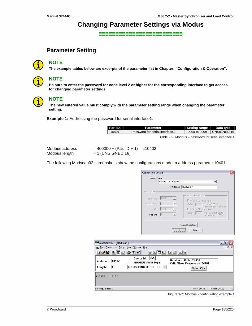
Manual 37444C MSLC-2 - Master Synchronizer and Load Control
© Woodward Page 185/220
Changing Parameter Settings via Modus
≡≡≡≡≡≡≡≡≡≡≡≡≡≡≡≡≡≡≡≡≡≡≡≡≡
Parameter Setting
NOTE The example tables below are excerpts of the parameter list in Chapter: “Configuration & Operation”.
NOTE Be sure to enter the password for code level 2 or higher for the corresponding interface to get access for changing parameter settings.
NOTE The new entered value must comply with the parameter setting range when changing the parameter setting.
Example 1: Addressing the password for serial interface1:
Par. ID. Parameter Setting range Data type
10401 Password for serial interface1 0000 to 9999 UNSIGNED 16
Table 9-9: Modbus – password for serial interface 1
Modbus address = 400000 + (Par. ID + 1) = 410402 Modbus length = 1 (UNSIGNED 16) The following Modscan32 screenshots show the configurations made to address parameter 10401.
Figure 9-7: Modbus - configuration example 1

Manual 37444C MSLC-2 - Master Synchronizer and Load Control
Page 186/220 © Woodward
Example 2: Addressing the generator rated voltage:
Par. ID. Parameter Setting range Data type
1766 Generator rated voltage 50 to 650000 V UNSIGNED 32
Table 9-10: Modbus – generator rated voltage
Modbus address = 40000 + (Par. ID + 1) = 41767 Modbus length = 2 (UNSIGNED 32) The following Modscan32 screenshot shows the configurations made to address parameter 1766.
Figure 9-8: Modbus - configuration example 2
Example 3: Addressing the generator voltage measuring:
Par. ID. Parameter Setting range Data type
1851 Generator voltage measuring 3Ph 4W 3Ph 3W
n/a n/a
3Ph 4WOD
UNSIGNED 16
Table 9-11: Modbus – generator voltage measuring
Modbus address = 40000 + (Par. ID + 1) = 41852 Modbus length = 1 (UNSIGNED 16)
NOTE If the setting range contains a list of parameter settings like in this example, the parameter settings are numbered and start with 0 for the first parameter setting. The number corresponding with the respec-tive parameter setting must be configured.
The following Modscan32 screenshot shows the configurations made to address parameter 1851, which is configured to "3Ph 4W".
Figure 9-9: Modbus - configuration example 3
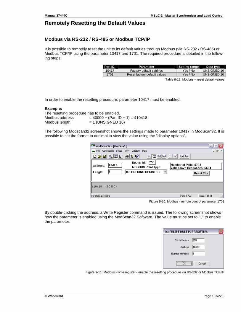
Manual 37444C MSLC-2 - Master Synchronizer and Load Control
© Woodward Page 187/220
Remotely Resetting the Default Values
Modbus via RS-232 / RS-485 or Modbus TCP/IP
It is possible to remotely reset the unit to its default values through Modbus (via RS-232 / RS-485) or Modbus TCP/IP using the parameter 10417 and 1701. The required procedure is detailed in the follow-ing steps.
Par. ID. Parameter Setting range Data type
10417 Factory default settings Yes / No UNSIGNED 16
1701 Reset factory default values Yes / No UNSIGNED 16
Table 9-12: Modbus – reset default values
In order to enable the resetting procedure, parameter 10417 must be enabled. Example: The resetting procedure has to be enabled. Modbus address = 40000 + (Par. ID + 1) = 410418 Modbus length = 1 (UNSIGNED 16) The following Modscan32 screenshot shows the settings made to parameter 10417 in ModScan32. It is possible to set the format to decimal to view the value using the "display options".
Figure 9-10: Modbus - remote control parameter 1701
By double-clicking the address, a Write Register command is issued. The following screenshot shows how the parameter is enabled using the ModScan32 Software. The value must be set to "1" to enable the parameter.
Figure 9-11: Modbus - write register - enable the resetting procedure via RS-232 or Modbus TCP/IP
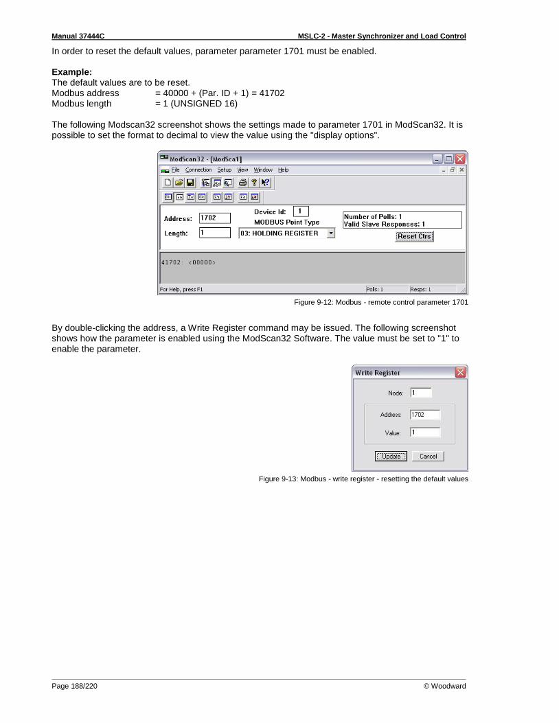
Manual 37444C MSLC-2 - Master Synchronizer and Load Control
Page 188/220 © Woodward
In order to reset the default values, parameter parameter 1701 must be enabled. Example: The default values are to be reset. Modbus address = 40000 + (Par. ID + 1) = 41702 Modbus length = 1 (UNSIGNED 16) The following Modscan32 screenshot shows the settings made to parameter 1701 in ModScan32. It is possible to set the format to decimal to view the value using the "display options".
Figure 9-12: Modbus - remote control parameter 1701
By double-clicking the address, a Write Register command may be issued. The following screenshot shows how the parameter is enabled using the ModScan32 Software. The value must be set to "1" to enable the parameter.
Figure 9-13: Modbus - write register - resetting the default values
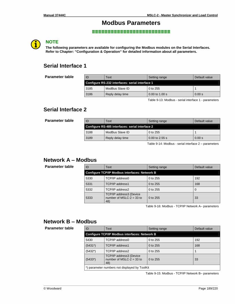
Manual 37444C MSLC-2 - Master Synchronizer and Load Control
© Woodward Page 189/220
Modbus Parameters
≡≡≡≡≡≡≡≡≡≡≡≡≡≡≡≡≡≡≡≡≡≡≡≡≡
NOTE The following parameters are available for configuring the Modbus modules on the Serial Interfaces. Refer to Chapter: “Configuration & Operation“ for detailed information about all parameters.
Serial Interface 1
Parameter table ID Text Setting range Default value
Configure RS-232 interfaces: serial interface 1
3185 ModBus Slave ID 0 to 255 1
3186 Reply delay time 0.00 to 1.00 s 0.00 s
Table 9-13: Modbus - serial interface 1 - parameters
Serial Interface 2
Parameter table ID Text Setting range Default value
Configure RS-485 interfaces: serial interface 2
3188 ModBus Slave ID 0 to 255 1
3189 Reply delay time 0.00 to 2.55 s 0.00 s
Table 9-14: Modbus - serial interface 2 – parameters
Network A – Modbus Parameter table
ID Text Setting range Default value
Configure TCP/IP Modbus interfaces: Network B
5330 TCP/IP address0 0 to 255 192
5331 TCP/IP address1 0 to 255 168
5332 TCP/IP address2 0 to 255 0
5333 TCP/IP address3 (Device number of MSLC-2 = 33 to 48)
0 to 255 33
Table 9-16: Modbus - TCP/IP Network A– parameters
Network B – Modbus Parameter table
ID Text Setting range Default value
Configure TCP/IP Modbus interfaces: Network B
5430 TCP/IP address0 0 to 255 192
(5431*) TCP/IP address1 0 to 255 168
(5432*) TCP/IP address2 0 to 255 1
(5433*) TCP/IP address3 (Device number of MSLC-2 = 33 to 48)
0 to 255 33
*) parameter numbers not displayed by ToolKit
Table 9-15: Modbus - TCP/IP Network B– parameters

Manual 37444C MSLC-2 - Master Synchronizer and Load Control
Page 190/220 © Woodward
Chapter 10. Application
Phase Angle Compensation
≡≡≡≡≡≡≡≡≡≡≡≡≡≡≡≡≡≡≡≡≡≡≡≡≡ This feature allows the MSLC-2 to adapt the phase angle measurement system according to the trans-former type. The phase angle of the "System B to System A" measurement can be compensated. The controller provides an adjustment for a phase angle deviation in a range of +/-180.0: "Phase angle MCB" (parameter 8842). This parameters compensate the phase angle deviation, which can be caused by transformers (i.e. a delta to wye transformer) located within the electrical system. The phase angle compensation is activated with the parameter "Phase angle compensation MCB" (pa-rameter 8841).
WARNING Ensure the parameters are configured correctly to prevent erroneous synchronization set-tings. Incorrect wiring of the system cannot be compensated with this parameter!
Fig. 201: Phase angle compensation MCB
Example Using the vector group 11 (Yd11) it counts α = 11 x 30 ° = 330 °. Because 330 ° > 180 ° and MSLC mains measurement is connected to the high voltage side this results into (-360 ° + α) to be used as phase difference. Enter -30 ° into as parameter for the phase difference Mains/Busbar.

Manual 37444C MSLC-2 - Master Synchronizer and Load Control
© Woodward Page 191/220
Appendix A. Technical Data
Nameplate
1 P/N Item number 2 REV Item revision number 3 S/N Serial number (numerical) 4 S/N Serial number (barcode) 5 S/N Date of production (year-month) 6 Type Description (short) 7 Type Description (long) 8 Details Technical data 9 Approval Approvals
Measuring values (voltages) – delta-wye voltage
Measuring voltages 120 V 480 V
Rated value (Vrated) 69/120 Vac 277/480 Vac
Maximum value (Vmax) Max. 86/150 Vac Max. 346/600 Vac
Rated voltage phase – ground 150 Vac 300 Vac
Rated surge voltage 2.5 kV 4.0 kV
Linear measuring range 1.25 × Vrated
Measuring frequency 50/60 Hz (40.0 to 85.0 Hz)
Accuracy Class 0.5
Input Resistance per path 120V → 0.498 MΩ 480 V → 2.0 MΩ
Maximum power consumption per path < 0.15 W
Measuring values (currents) – isolated
Measuring current [1] Rated value (Irated) → ../1 A [5] Rated value (Irated) → ../5 A
Accuracy Class 0.5
Linear measuring range 1.5 × Irated
Maximum power consumption per path < 0.15 VA
Rated short-time current (1 s) [1] → 50.0 × Irated [5] → 10.0 × Irated
Ambient variables
Power supply 12/24 Vdc (8 to 40 Vdc)
Intrinsic consumption Max. 15W
Insulation voltage (continuously) 40 Vac
Insulation test voltage (1 s) 100 Vac
Overvoltage (≤ 2 min) 80 Vdc
Reverse voltage protection Full supply range
Grounding supply voltage source Isolated, negative potential or positive potential grounded

Manual 37444C MSLC-2 - Master Synchronizer and Load Control
Page 192/220 © Woodward
(Ambient variables)
Degree of pollution 2
Maximum elevation 2000 m ASL
Discrete inputs – isolated
Input range (Vcont. dig. input) Rated voltage 12/24 Vdc (8 to 40.0 Vdc)
Input resistance Approx. 20 kΩ
Discrete outputs – potential free
Contact material AgCdO
General purpose (GP) (Vcont, relays) AC DC
2.00 Aac@250 Vac 2.00 Adc@24 Vdc 0.36 Adc@125 Vdc 0.18 Adc@250 Vdc
Pilot duty (PD) (Vcont, relays) AC DC
B300 1.00 Adc@24 Vdc 0.22 Adc@125 Vdc 0.10 Adc@250 Vdc
Analog inputs (none isolated) – freely scalable
Maximum permissible voltage against PE (Ground)
15 V
Resolution 11 Bit
0 to 20 mA input Internal load 124 Ω
0 to 10 V input Input resistance approx. 80 kΩ
Accuracy 1.0%
Interface
RS-232 interface Isolated
Insulation voltage (continuously) 100 Vac
Insulation test voltage (1 s) 500 Vac
Version RS-232 Standard
RS-485 interface Isolated
Insulation voltage (continuously) 100 Vac
Insulation test voltage (1 s) 500 Vac
Version RS-485 Standard
Ethernet interface Isolated
Insulation test voltage (1 s) 500 Vac
Version 100 Mbit/s
Battery
Type Lithium
Life span (operation without power supply) Approx. 5 years
Battery field replacement Not allowed
Housing
Type Sheet metal → Custom
Dimensions (W × H × D) Sheet metal → 250 × 227 × 84 mm (9.84 × 9.00 × 3.30 in)
Wiring Screw-plug-terminals 2.5 mm²
Recommended locked torque 4 inch pounds / 0.5 Nm Use 60/75 °C copper wire only Use class 1 wire only or equivalent
Weight approx. 1,900 g (4.2 lbs)
Protection
Protection system IP 20
EMC test (CE) Tested according to applicable EN guidelines
Certifications
Listings CE marking; cUL/UL ordinary Locations, File No. 231544; GOST-R; CSA
Marine Type approval: Lloyds Register (LR) Type approval: American Bureau of Shipping (ABS)
Generic note
Accuracy Is referred to full scale value
Table 10-1: Technical Data

Manual 37444C MSLC-2 - Master Synchronizer and Load Control
© Woodward Page 193/220
Appendix B. Environmental Data
Vibration
Frequency Range – Sine Sweep 5 Hz to 100 Hz
Acceleration 4G
Frequency Range – Random 10 Hz to 500 Hz
Power Intensity 0.015G² / Hz
RMS Value 1.04 Grms
Standards
EN 60255-21-1 (EN 60068-2-6, Fc) EN 60255-21-3 Lloyd’s Register, Vibration Test2 SAEJ1455 Chassis Data MIL-STD 810F, M514.5A, Cat.4, Truck/Trailer tracked-restrained Cargo, Fig. 514.5-C1
Shock
Shock 40G, Saw tooth pulse, 11 ms
Standards EN 60255-21-2 MIL-STD 810F, M516.5, Procedure 1
Temperature
Cold, Dry Heat (storage) -40 °C (-40 °F) / 85 °C (185 °F)
Cold, Dry Heat (operating) -40 °C (-40 °F) / 70 °C (158 °F)
Standards IEC 60068-2-2, Test Bb and Bd IEC 60068-2-1, Test Ab and Ad
Humidity
Humidity 60 °C, 95% RH, 5 days
Standards IEC 60068-2-30, Test DB
Marine Environmental Categories
Lloyd’s Register of Shipping (LRS) ENV1, ENV2, ENV3 and ENV4
Table 10-2: Environmental Data

Manual 37444C MSLC-2 - Master Synchronizer and Load Control
Page 194/220 © Woodward
Appendix C. Accuracy
Measuring value Display Accuracy Measuring start Notes
Frequency
Generator 15.0 to 85.0 Hz 0.2% (of 85 Hz)
5% (of PT second-ary voltage setting)
1
Busbar 40.0 to 85.0 Hz
Voltage
Wye generator / mains / busbar
0 to 650 kV 0.5% (of 150/600 V)
2
1.5% (of PT sec-ondary voltage set-ting)
1
Delta generator / mains / busbar
2% (of PT second-ary voltage setting)
1
Current
Generator
0 to 32,000 A 0.5% (of 1.3/6.5 A)
3
1% (of 1/5 A) 3 Mains / ground current
Max. value
Real power
Actual total real power value -2 to 2 GW 1% (of 150/600 V * 1.3/6.5 A)
2/3
Starts with detecting the zero passage of current/voltage
Reactive power
Actual value in L1, L2, L3 -2 to 2 Gvar 1% (of 150/600 V * 1.3/6.5 A)
2/3
Starts with detecting the zero passage of current/voltage
Power factor
Actual value power factor L1 Lagging 0.00 to 1.00 to leading 0.00
2% 2% (of 1/5 A) 3
1.00 is displayed for measuring val-ues below the measuring start
Miscellaneous
Power supply 8 to 40 V 1% (of 24 V)
Phase angle -180 to 180 ° 1.25% (of PT sec-ondary volt. setting)
180 ° is displayed for measuring val-ues below measur-ing start
Miscellaneous
0 to 20 mA / 0 to 10 V Freely scalable 1.2% (of 20 mA) / 1.2% (of 10 V)
Table 10-3: Accuracy
1 Setting of the parameter for the PT secondary rated voltage
2 Depending on the used measuring inputs (100/400 V)
3 Depending on the CT input hardware (1/5 A) of the respective unit
Reference conditions (for measuring the accuracy):
Input voltage ................ sinusoidal rated voltage
Input current ................. sinusoidal rated current
Frequency .................... rated frequency +/- 2%
Power supply ............... rated voltage +/- 2%
Power factor (cos φ) .... 1.00
Ambient temperature ... 23 °C +/- 2 K
Warm-up period ........... 20 minutes

Manual 37444C MSLC-2 - Master Synchronizer and Load Control
© Woodward Page 195/220
Appendix D. Useful Information
Connecting 24 V Relays
≡≡≡≡≡≡≡≡≡≡≡≡≡≡≡≡≡≡≡≡≡≡≡≡≡ Interferences in the interaction of all components may affect the function of electronic devices. One interference factor is disabling inductive loads, like coils of electromagnetic switching devices. When disabling such a device, high switch-off induces voltages may occur, which might destroy adja-cent electronic devices or result interference voltage pulses, which lead to functional faults, by capaci-tive coupling mechanisms. Since an interference-free switch-off is not possible without additional equipment, the relay coil is con-nected with an interference suppressing circuit. If 24 V (coupling) relays are used in an application, it is required to connect a protection circuit to avoid interferences. Figure 10-1 shows the exemplary connection of a diode as an interfer-ence suppressing circuit.
Figure 10-1: Interference suppressing circuit - connection
Advantages and disadvantages of different interference suppressing circuits are described in the fol-lowing.
Connection diagram Load current / voltage curve
Advantages Disadvantages
Uncritical dimensioning
Lowest possible induced volt-age
Very simple and reliable
High release delay
Uncritical dimensioning
High energy absorption
Very simple setup
Suitable for AC voltage
Reverse polarity protected
No attenuation below VVDR
HF attenuation by energy storage
Immediate shut-off limiting
Attenuation below limiting voltage
Very suitable for AC voltage
Reverse polarity protected
Exact dimensioning re-quired
Table 10-4: Interference suppressing circuit for relays
+
0
v
t
t0
i
t0
I0
V0
t2t1
^V
~
~
VDR
0
v
t
t0
i
t0
I0
t1 t2
^V
V0
~
~C
R
0
v
t
0 t
i
t0
I0
V0
T1
Relayoutput
Powersupply
Control unit
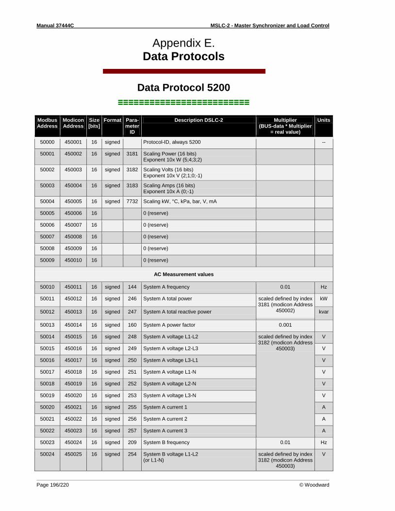
Manual 37444C MSLC-2 - Master Synchronizer and Load Control
Page 196/220 © Woodward
Appendix E. Data Protocols
Data Protocol 5200
≡≡≡≡≡≡≡≡≡≡≡≡≡≡≡≡≡≡≡≡≡≡≡≡≡
Modbus Address
Modicon Address
Size [bits]
Format Para-meter
ID
Description DSLC-2 Multiplier (BUS-data * Multiplier
= real value)
Units
50000 450001 16 signed Protocol-ID, always 5200 --
50001 450002 16 signed 3181 Scaling Power (16 bits) Exponent 10x W (5;4;3;2)
50002 450003 16 signed 3182 Scaling Volts (16 bits) Exponent 10x V (2;1;0;-1)
50003 450004 16 signed 3183 Scaling Amps (16 bits) Exponent 10x A (0;-1)
50004 450005 16 signed 7732 Scaling kW, °C, kPa, bar, V, mA
50005 450006 16 0 (reserve)
50006 450007 16 0 (reserve)
50007 450008 16 0 (reserve)
50008 450009 16 0 (reserve)
50009 450010 16 0 (reserve)
AC Measurement values
50010 450011 16 signed 144 System A frequency 0.01 Hz
50011 450012 16 signed 246 System A total power scaled defined by index 3181 (modicon Address
450002)
kW
50012 450013 16 signed 247 System A total reactive power kvar
50013 450014 16 signed 160 System A power factor 0.001
50014 450015 16 signed 248 System A voltage L1-L2 scaled defined by index 3182 (modicon Address
450003)
V
50015 450016 16 signed 249 System A voltage L2-L3 V
50016 450017 16 signed 250 System A voltage L3-L1 V
50017 450018 16 signed 251 System A voltage L1-N V
50018 450019 16 signed 252 System A voltage L2-N V
50019 450020 16 signed 253 System A voltage L3-N V
50020 450021 16 signed 255 System A current 1 A
50021 450022 16 signed 256 System A current 2 A
50022 450023 16 signed 257 System A current 3 A
50023 450024 16 signed 209 System B frequency 0.01 Hz
50024 450025 16 signed 254 System B voltage L1-L2 (or L1-N)
scaled defined by index 3182 (modicon Address
450003)
V
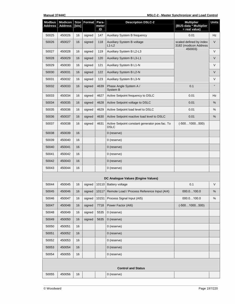
Manual 37444C MSLC-2 - Master Synchronizer and Load Control
© Woodward Page 197/220
Modbus Address
Modicon Address
Size [bits]
Format Para-meter
ID
Description DSLC-2 Multiplier (BUS-data * Multiplier
= real value)
Units
50025 450026 16 signed 147 Auxiliary System B frequency 0.01 Hz
50026 450027 16 signed 118 Auxiliary System B voltage L1-L2
scaled defined by index 3182 (modicon Address
450003)
V
50027 450028 16 signed 119 Auxiliary System B L2-L3 V
50028 450029 16 signed 120 Auxiliary System B L3-L1 V
50029 450030 16 signed 121 Auxiliary System B L1-N V
50030 450031 16 signed 122 Auxiliary System B L2-N V
50031 450032 16 signed 123 Auxiliary System B L3-N V
50032 450033 16 signed 4639 Phase Angle System A / System B
0.1 °
50033 450034 16 signed 4627 Active Setpoint frequency to DSLC 0.01 Hz
50034 450035 16 signed 4628 Active Setpoint voltage to DSLC 0.01 %
50035 450036 16 signed 4629 Active Setpoint load level to DSLC 0.01 %
50036 450037 16 signed 4630 Active Setpoint reactive load level to DSLC 0.01 %
50037 450038 16 signed 4631 Active Setpoint constant generator pow.fac. To DSLC
(-500…1000...500)
50038 450039 16 0 (reserve)
50039 450040 16 0 (reserve)
50040 450041 16 0 (reserve)
50041 450042 16 0 (reserve)
50042 450043 16 0 (reserve)
50043 450044 16 0 (reserve)
DC Analogue Values (Engine Values)
50044 450045 16 signed 10110 Battery voltage 0.1 V
50045 450046 16 signed 10117 Remote Load / Process Reference Input (AI4) 000.0…100.0 %
50046 450047 16 signed 10151 Process Signal Input (AI5) 000.0…100.0 %
50047 450048 16 signed 7718 Power Factor (AI6) (-500…1000...500)
50048 450049 16 signed 5535 0 (reserve)
50049 450050 16 signed 5635 0 (reserve)
50050 450051 16 0 (reserve)
50051 450052 16 0 (reserve)
50052 450053 16 0 (reserve)
50053 450054 16 0 (reserve)
50054 450055 16 0 (reserve)
Control and Status
50055 450056 16 0 (reserve)
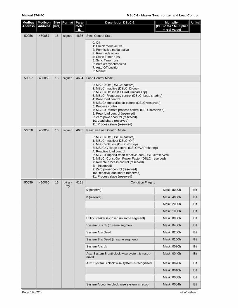
Manual 37444C MSLC-2 - Master Synchronizer and Load Control
Page 198/220 © Woodward
Modbus Address
Modicon Address
Size [bits]
Format Para-meter
ID
Description DSLC-2 Multiplier (BUS-data * Multiplier
= real value)
Units
50056 450057 16 signed 4636 Sync Control State
0: Off 1: Check mode active 2: Permissive mode active 3: Run mode active 4: Close Timer runs 5: Sync Timer runs 6: Breaker synchronized 7: Auto-Off position 8: Manual
50057 450058 16 signed 4634 Load Control Mode
0: MSLC=Off (DSLC=Inactive) 1: MSLC=Inactive (DSLC=Droop) 2: MSLC=Off line (SLC=At Unload Trip) 3: MSLC=Frequency control (DSLC=Load sharing) 4: Base load control 5: MSLC=Import/Export control (DSLC=reserved) 6: Process control 7: MSLC=Remote process control (DSLC=reserved) 8: Peak load control (reserved) 9: Zero power control (reserved) 10: Load share (reserved) 11: Process slave (reserved)
50058 450059 16 signed 4635 Reactive Load Control Mode
0: MSLC=Off (DSLC=Inactive) 1: MSLC=Inactive( DSLC=Off) 2: MSLC=Off line (DSLC=Droop) 3: MSLC=Voltage control (DSLC=VAR sharing) 4: Reactive load control 5: MSLC=Import/Export reactive load (DSLC=reserved) 6: MSLC=Const.Gen Power Factor (DSLC=reserved) 7: Remote process control (reserved) 8: - (reserved) 9: Zero power control (reserved) 10: Reactive load share (reserved) 11: Process slave (reserved)
50059 450060 16 bit ar-ray
4151 Condition Flags 1
0 (reserve) Mask: 8000h Bit
0 (reserve) Mask: 4000h Bit
Mask: 2000h Bit
Mask: 1000h Bit
Utility breaker is closed (in same segment) Mask: 0800h Bit
System B is ok (in same segment) Mask: 0400h Bit
System A is Dead Mask: 0200h Bit
System B is Dead (in same segment) Mask: 0100h Bit
System A is ok Mask: 0080h Bit
Aux. System B anti clock wise system is recog-nized
Mask: 0040h Bit
Aux. System B clock wise system is recognized Mask: 0020h Bit
Mask: 0010h Bit
Mask: 0008h Bit
System A counter clock wise system is recog- Mask: 0004h Bit

Manual 37444C MSLC-2 - Master Synchronizer and Load Control
© Woodward Page 199/220
Modbus Address
Modicon Address
Size [bits]
Format Para-meter
ID
Description DSLC-2 Multiplier (BUS-data * Multiplier
= real value)
Units
nized
System A clock wise system is recognized Mask: 0002h Bit
Mask: 0001h Bit
50060 450061 16 bit ar-ray
4156 Condition Flags 2
0 (reserve) Mask: 8000h Bit
0 (reserve) Mask: 4000h Bit
0 (reserve) Mask: 2000h Bit
0 (reserve) Mask: 1000h Bit
0 (reserve) Mask: 0800h Bit
Breaker dead busbar closure request active Mask: 0400h Bit
0 (reserve) Mask: 0200h Bit
0 (reserve) Mask: 0100h Bit
0 (reserve) Mask: 0080h Bit
0 (reserve) Mask: 0040h Bit
0 (reserve) Mask: 0020h Bit
0 (reserve) Mask: 0010h Bit
0 (reserve) Mask: 0008h Bit
0 (reserve) Mask: 0004h Bit
0 (reserve) Mask: 0002h Bit
0 (reserve) Mask: 0001h Bit
50061 450062 16 bit ar-ray
4155 Condition Flags 3
0 (reserve) Mask: 8000h Bit
0 (reserve) Mask: 4000h Bit
0 (reserve) Mask: 2000h Bit
0 (reserve) Mask: 1000h Bit
Breaker is closed Mask: 0800h Bit
0 (reserve) Mask: 0400h Bit
0 (reserve) Mask: 0200h Bit
Synchronization Breaker is active
Mask: 0100h Bit
Opening Breaker is active Mask: 0080h Bit
Closing Breaker is active Mask: 0040h Bit
0 (reserve) Mask: 0020h Bit
0 (reserve) Mask: 0010h Bit
0 (reserve) Mask: 0008h Bit
Unloading system is active Mask: 0004h Bit

Manual 37444C MSLC-2 - Master Synchronizer and Load Control
Page 200/220 © Woodward
Modbus Address
Modicon Address
Size [bits]
Format Para-meter
ID
Description DSLC-2 Multiplier (BUS-data * Multiplier
= real value)
Units
0 (reserve) Mask: 0002h Bit
0 (reserve) Mask: 0001h Bit
50062 450063 16 signed 4637 Automatic Segment Allocation (ASA) 1...8
50063 450064 16 signed 4638 Collective Breaker State (CBS) 0…255
50064 450065 16 signed 7706 0 (reserve)
50065 450066 16 signed 4503 0 (reserve)
50066 450067 16 signed 4600 Process Signal Input 000.00…100.0 %
50067 450068 16 bit ar-ray
4157 Interface Control Switch
0 (reserve) Mask: 8000h Bit
Source: System update switch Mask: 4000h Bit
Source: Modbus reset switch Mask: 2000h Bit
Source: Droop switch Mask: 1000h Bit
Source: Process switch Mask: 0800h Bit
Source: Lower load switch Mask: 0400h Bit
Source: Raise load switch Mask: 0200h Bit
Source: Ramp pause switch Mask: 0100h Bit
Source: Load/ Unload switch Mask: 0080h Bit
Source: Base load switch Mask: 0040h Bit
Source: Lower voltage switch Mask: 0020h Bit
Source: Raise voltage switch Mask: 0010h Bit
Source: CB Aux contact switch Mask: 0008h Bit
Source: Synchronization GCB run switch Mask: 0004h Bit
Source: Synchronization GCB permissive switch Mask: 0002h Bit
Source: Synchronization GCB check switch Mask: 0001h Bit
50068 450069 16 signed 4605 Process reference 000.00…100.0 %
50069 450070 16 signed 7708 Power factor reference (-0.500… 1.000...0.500)
50070 450071 16 0 (reserve)
Relay Outputs
50071 450072 16 bit ar-ray
4626 Relay Outputs 1
0 (reserve) Mask: 8000h Bit
0 (reserve) Mask: 4000h Bit
0 (reserve) Mask: 2000h Bit
0 (reserve) Mask: 1000h Bit
Load switch 2 (R12) Mask: 0800h Bit
Load switch 1 (R11) Mask: 0400h Bit
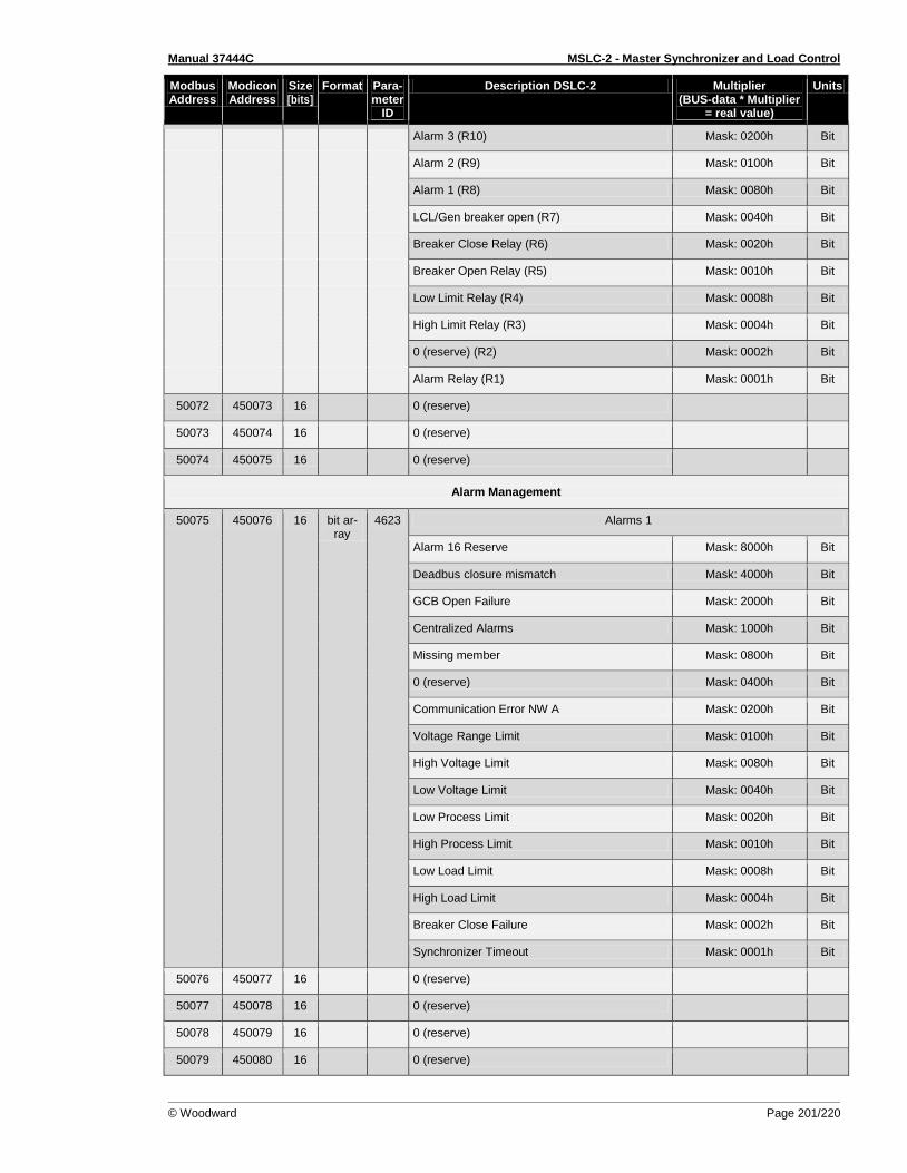
Manual 37444C MSLC-2 - Master Synchronizer and Load Control
© Woodward Page 201/220
Modbus Address
Modicon Address
Size [bits]
Format Para-meter
ID
Description DSLC-2 Multiplier (BUS-data * Multiplier
= real value)
Units
Alarm 3 (R10) Mask: 0200h Bit
Alarm 2 (R9) Mask: 0100h Bit
Alarm 1 (R8) Mask: 0080h Bit
LCL/Gen breaker open (R7) Mask: 0040h Bit
Breaker Close Relay (R6) Mask: 0020h Bit
Breaker Open Relay (R5) Mask: 0010h Bit
Low Limit Relay (R4) Mask: 0008h Bit
High Limit Relay (R3) Mask: 0004h Bit
0 (reserve) (R2) Mask: 0002h Bit
Alarm Relay (R1) Mask: 0001h Bit
50072 450073 16 0 (reserve)
50073 450074 16 0 (reserve)
50074 450075 16 0 (reserve)
Alarm Management
50075 450076 16 bit ar-ray
4623 Alarms 1
Alarm 16 Reserve Mask: 8000h Bit
Deadbus closure mismatch Mask: 4000h Bit
GCB Open Failure Mask: 2000h Bit
Centralized Alarms Mask: 1000h Bit
Missing member Mask: 0800h Bit
0 (reserve) Mask: 0400h Bit
Communication Error NW A Mask: 0200h Bit
Voltage Range Limit Mask: 0100h Bit
High Voltage Limit Mask: 0080h Bit
Low Voltage Limit Mask: 0040h Bit
Low Process Limit Mask: 0020h Bit
High Process Limit Mask: 0010h Bit
Low Load Limit Mask: 0008h Bit
High Load Limit Mask: 0004h Bit
Breaker Close Failure Mask: 0002h Bit
Synchronizer Timeout Mask: 0001h Bit
50076 450077 16 0 (reserve)
50077 450078 16 0 (reserve)
50078 450079 16 0 (reserve)
50079 450080 16 0 (reserve)
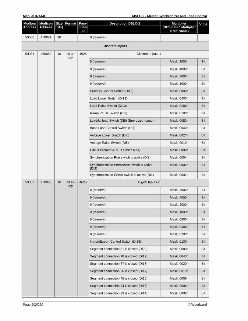
Manual 37444C MSLC-2 - Master Synchronizer and Load Control
Page 202/220 © Woodward
Modbus Address
Modicon Address
Size [bits]
Format Para-meter
ID
Description DSLC-2 Multiplier (BUS-data * Multiplier
= real value)
Units
50080 450081 16 0 (reserve)
Discrete Inputs
50081 450082 16 bit ar-ray
4624 Discrete Inputs 1
0 (reserve) Mask: 8000h Bit
0 (reserve) Mask: 4000h Bit
0 (reserve) Mask: 2000h Bit
0 (reserve) Mask: 1000h Bit
Process Control Switch (DI12) Mask: 0800h Bit
Load Lower Switch (DI11) Mask: 0400h Bit
Load Raise Switch (DI10) Mask: 0200h Bit
Ramp Pause Switch (DI9) Mask: 0100h Bit
Load/Unload Switch (DI8) (Energized=Load) Mask: 0080h Bit
Base Load Control Switch (DI7) Mask: 0040h Bit
Voltage Lower Switch (DI6) Mask: 0020h Bit
Voltage Raise Switch (DI5) Mask: 0010h Bit
Circuit Breaker Aux. is closed (DI4) Mask: 0008h Bit
Synchronization Run switch is active (DI3) Mask: 0004h Bit
Synchronization Permissive switch is active (DI2)
Mask: 0002h Bit
Synchronization Check switch is active (DI1) Mask: 0001h Bit
50082 450083 16 bit ar-ray
4625 Digital Inputs 2
0 (reserve) Mask: 8000h Bit
0 (reserve) Mask: 4000h Bit
0 (reserve) Mask: 2000h Bit
0 (reserve) Mask: 1000h Bit
0 (reserve) Mask: 0800h Bit
0 (reserve) Mask: 0400h Bit
0 (reserve) Mask: 0200h Bit
Import/Export Control Switch (DI13) Mask: 0100h Bit
Segment connection 81 is closed (DI20) Mask: 0080h Bit
Segment connection 78 is closed (DI19) Mask: 0040h Bit
Segment connection 67 is closed (DI18) Mask: 0020h Bit
Segment connection 56 is closed (DI17) Mask: 0010h Bit
Segment connection 45 is closed (DI16) Mask: 0008h Bit
Segment connection 34 is closed (DI15) Mask: 0004h Bit
Segment connection 23 is closed (DI14) Mask: 0002h Bit
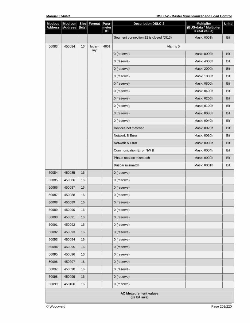
Manual 37444C MSLC-2 - Master Synchronizer and Load Control
© Woodward Page 203/220
Modbus Address
Modicon Address
Size [bits]
Format Para-meter
ID
Description DSLC-2 Multiplier (BUS-data * Multiplier
= real value)
Units
Segment connection 12 is closed (DI13) Mask: 0001h Bit
50083 450084 16 bit ar-ray
4601 Alarms 5
0 (reserve) Mask: 8000h Bit
0 (reserve) Mask: 4000h Bit
0 (reserve) Mask: 2000h Bit
0 (reserve) Mask: 1000h Bit
0 (reserve) Mask: 0800h Bit
0 (reserve) Mask: 0400h Bit
0 (reserve) Mask: 0200h Bit
0 (reserve) Mask: 0100h Bit
0 (reserve) Mask: 0080h Bit
0 (reserve) Mask: 0040h Bit
Devices not matched Mask: 0020h Bit
Network B Error Mask: 0010h Bit
Network A Error Mask: 0008h Bit
Communication Error NW B Mask: 0004h Bit
Phase rotation mismatch Mask: 0002h Bit
Busbar mismatch Mask: 0001h Bit
50084 450085 16 0 (reserve)
50085 450086 16 0 (reserve)
50086 450087 16 0 (reserve)
50087 450088 16 0 (reserve)
50088 450089 16 0 (reserve)
50089 450090 16 0 (reserve)
50090 450091 16 0 (reserve)
50091 450092 16 0 (reserve)
50092 450093 16 0 (reserve)
50093 450094 16 0 (reserve)
50094 450095 16 0 (reserve)
50095 450096 16 0 (reserve)
50096 450097 16 0 (reserve)
50097 450098 16 0 (reserve)
50098 450099 16 0 (reserve)
50099 450100 16 0 (reserve)
AC Measurement values (32 bit size)

Manual 37444C MSLC-2 - Master Synchronizer and Load Control
Page 204/220 © Woodward
Modbus Address
Modicon Address
Size [bits]
Format Para-meter
ID
Description DSLC-2 Multiplier (BUS-data * Multiplier
= real value)
Units
50100 450101 32 signed 135 Total System A power 1 W
50102 450103 32 signed 136 Total System A reactive power 1 var
50104 450105 32 signed 137 Total System A apparent power 1 VA
50106 450107 32 signed 170 Average System A Wye-Voltage 0.1 V
50108 450109 32 signed 171 Average System A Delta-Voltage 0.1 V
50110 450111 32 signed 216 Average System B Delta-Voltage 0.1 V
50112 450113 32 signed 185 Average System A Current 0.001 A
50114 450115 32 signed 111 System A current 1 0.001 A
50116 450117 32 signed 112 System A current 2 0.001 A
50118 450119 32 signed 113 System A current 3 0.001 A
50120 450121 32 signed 108 System A voltage L1-L2 0.1 V
50122 450123 32 signed 109 System A voltage L2-L3 0.1 V
50124 450125 32 signed 110 System A voltage L3-L1 0.1 V
50126 450127 32 signed 114 System A voltage L1-N 0.1 V
50128 450129 32 signed 115 System A voltage L2-N 0.1 V
50130 450131 32 signed 116 System A voltage L3-N 0.1 V
50132 450133 32 signed 125 System A active power 1-N 1 W
50134 450135 32 signed 126 System A active power 2-N 1 W
50136 450137 32 signed 127 System A active power 3-N 1 W
50138 450139 32 signed 182 System B voltage (L1-N) L1-L2 0.1 V
50140 450141 32 signed 173 Average Aux.System B Wye-Voltage 0.1 V
50142 450143 32 signed 174 Average Aux.System B Delta-Voltage 0.1 V
50144 450145 32 signed 118 Aux.System B voltage L1-L2 0.1 V
50146 450147 32 signed 119 Aux.System B voltage L2-L3 0.1 V
50148 450149 32 signed 120 Aux.System B voltage L3-L1 0.1 V
50150 450151 32 signed 121 Aux.System B voltage L1-N 0.1 V
50152 450153 32 signed 122 Aux.System B voltage L2-N 0.1 V
50154 450155 32 signed 123 Aux.System B voltage L3-N 0.1 V
50156 450157 32 signed 7719 P Sum 0.001 kW
50158 450159 32 signed 7720 Q Sum 0.001 kVAR
50160 450161 32 signed 7721 Import/Export reference 0.1 kW
50162 450163 32 signed 7722 Reactive load reference 0.1 kVAR
50164 450165 32 signed 7726 Process reference input 0.1
50166 450167 32 signed 7727 Process signal input 0.1
50168 450169 32 signed 7737 Process reference toolkit 0.1
50170 450171 32 signed 7738 Remote load reference input 0.1 kW

Manual 37444C MSLC-2 - Master Synchronizer and Load Control
© Woodward Page 205/220
Modbus Address
Modicon Address
Size [bits]
Format Para-meter
ID
Description DSLC-2 Multiplier (BUS-data * Multiplier
= real value)
Units
50172 450173 32 0 (reserve)
50174 450175 32 signed 2520 Syst.A.pos.act.energy 0.01 MWh
50176 450177 32 signed 2524 Syst.A.neg.act.energy 0.01 MWh
50178 450179 32 signed 2522 Syst.A.pos.react.energy 0.01 Mvarh
50180 450181 32 signed 2526 Syst.A.neg.react.energy 0.01 Mvarh
50182 450183 32 signed 2568 0 (reserve) 0.01 h
Table 10-5: Data Protocol 5200
Manual 37444C MSLC-2 - Master Synchronizer and Load Control
Page 206/220 © Woodward
Appendix F. Parameter Overview
Introduction
≡≡≡≡≡≡≡≡≡≡≡≡≡≡≡≡≡≡≡≡≡≡≡≡≡
Parameter List Columns The parameter list consists of the following columns, which provide important information for each pa-rameter:
NamespaceX
The namespaces 1 and 2 are used to combine all parameters within functional groups.
ID
The parameter ID is a unique identifier for each individual parameter. It is mentioned besides each pa-rameter in ToolKit and also required when configuring the unit via interface.
Parameter Text
The parameter text describes the parameter and appears on the configuration screens of the unit and ToolKit.
Setting Range
The setting range describes the range for possible parameter settings and may either be a range (e.g. 0 to 9), or a selection of different options (e.g. Yes or No). If the respective parameter allows configur-ing different options, the number behind each option is the number, which needs to be transmitted via interface to select this option.
Default Value
The default value is the parameter setting at delivery of the unit or after resetting the unit to factory set-tings. If the parameter allows configuring different options, the default value describes the number of the respective option.
Data Type
The data type indicates the data type of the respective parameter. The following data types are possi-ble:
UNSIGNED8 unsigned 8 bit integer
UNSIGNED16 unsigned 16 bit integer
UNSIGNED32 unsigned 32 bit integer
SIGNED32 signed 32 bit integer
INTEGER16 16 bit integer
Code Level (CL)
This is the minimum code level, which is required to access the respective parameter.

Manual 37444C MSLC-2 - Master Synchronizer and Load Control
© Woodward Page 207/220
Parameter List
≡≡≡≡≡≡≡≡≡≡≡≡≡≡≡≡≡≡≡≡≡≡≡≡≡
(Sequence following ID number)
ID Menu Parameter Text Setting range Default value
Data Type CL
521 - Lamp test No ; 0 Yes ; 1
UNSIGNED 16 0
1701 MENU 5.2 Reset factory default values No ; 0 Yes ; 1
0 UNSIGNED 16 0
1750 MENU 5 System rated frequency 50Hz ; 0 60Hz ; 1
1 UNSIGNED 16 2
1770 MENU 4 System A voltage monitoring Phase - phase ; 0
Phase - neutral ; 1 0 UNSIGNED 16 2
1850 MENU 5 System A current input
L1 L2 L3 ; 0 Phase L1 ; 1 Phase L2 ; 2 Phase L3 ; 3
0 UNSIGNED 16 2
1851 MENU 5 System A voltage measuring
3Ph 4W ; 0 3Ph 3W ; 1 1Ph 2W ; 2
n/a1 ; 3 3Ph 4W OD ; 4
1 UNSIGNED 16 2
1853 MENU 5 Aux system B voltage meas. 3Ph 4W ; 0 3Ph 3W ; 1
1 UNSIGNED 16 2
1858 MENU 5 1Ph2W voltage input Phase - neutral ; 0 Phase - phase ; 1
1 UNSIGNED 16 2
1859 MENU 5 1Ph2W phase rotation CW ; 0
CCW ; 1 0 UNSIGNED 16 2
2510 MENU 5.3 Syst. A active energy [0.00MWh] No ; 0 Yes ; 1
0 UNSIGNED 16 2
2511 MENU 5.3 Syst. A react. energy [0.00Mvarh] No ; 0 Yes ; 1
0 UNSIGNED 16 2
2512 MENU 5.3 Syst. A active energy -[0.00MWh] No ; 0 Yes ; 1
0 UNSIGNED 16 2
2513 MENU 5.3 Syst. A react. energy -[0.00Mvarh] No ; 0 Yes ; 1
0 UNSIGNED 16 2
3163 MENU 5.1 Baudrate
9600 Bd ; 0 14.4 kBd ; 1 19.2 kBd ; 2 38.4 kBd ; 3 56 kBd ; 4
115 kBd ; 5
2 UNSIGNED 16 2
3170 MENU 5.1 Baudrate
9600 Bd ; 0 14.4 kBd ; 1 19.2 kBd ; 2 38.4 kBd ; 3 56 kBd ; 4
115 kBd ; 5
2 UNSIGNED 16 2
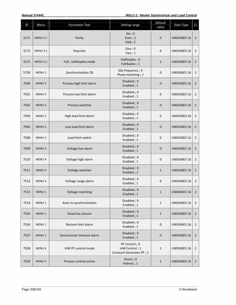
Manual 37444C MSLC-2 - Master Synchronizer and Load Control
Page 208/220 © Woodward
ID Menu Parameter Text Setting range Default value
Data Type CL
3171 MENU 5.1 Parity No ; 0
Even ; 1 Odd ; 2
0 UNSIGNED 16 2
3172 MENU 5.1 Stop bits One ; 0 Two ; 1
0 UNSIGNED 16 2
3173 MENU 5.1 Full-, halfduplex mode Halfduplex ; 0 Fullduplex ; 1
1 UNSIGNED 16 2
5730 MENU 1 Synchronization CB Slip frequency ; 0
Phase matching ; 1 0 UNSIGNED 16 2
7500 MENU 3 Process high limit alarm Disabled ; 0 Enabled ; 1
0 UNSIGNED 16 2
7501 MENU 3 Process low limit alarm Disabled ; 0 Enabled ; 1
0 UNSIGNED 16 2
7502 MENU 3 Process switches Disabled ; 0 Enabled ; 1
0 UNSIGNED 16 2
7504 MENU 2 High load limit alarm Disabled ; 0 Enabled ; 1
0 UNSIGNED 16 2
7505 MENU 2 Low load limit alarm Disabled ; 0 Enabled ; 1
0 UNSIGNED 16 2
7506 MENU 2 Load limit switch Disabled ; 0 Enabled ; 1
0 UNSIGNED 16 2
7509 MENU 4 Voltage low alarm Disabled ; 0 Enabled ; 1
0 UNSIGNED 16 2
7510 MENU 4 Voltage high alarm Disabled ; 0 Enabled ; 1
0 UNSIGNED 16 2
7511 MENU 4 Voltage switches Disabled ; 0 Enabled ; 1
1 UNSIGNED 16 2
7512 MENU 4 Voltage range alarm Disabled ; 0 Enabled ; 1
0 UNSIGNED 16 2
7513 MENU 1 Voltage matching Disabled ; 0 Enabled ; 1
1 UNSIGNED 16 2
7514 MENU 1 Auto re-synchronization Disabled ; 0 Enabled ; 1
1 UNSIGNED 16 2
7555 MENU 1 Dead bus closure Disabled ; 0 Enabled ; 1
1 UNSIGNED 16 2
7556 MENU 1 Reclose limit alarm Disabled ; 0 Enabled ; 1
0 UNSIGNED 16 2
7557 MENU 1 Synchronizer timeout alarm Disabled ; 0 Enabled ; 1
0 UNSIGNED 16 2
7558 MENU 4 VAR PF control mode PF Control ; 0
VAR Control ; 1 Constant Generator PF ; 2
1 UNSIGNED 16 2
7559 MENU 3 Process control action Direct ; 0
Indirect ; 1 1 UNSIGNED 16 2
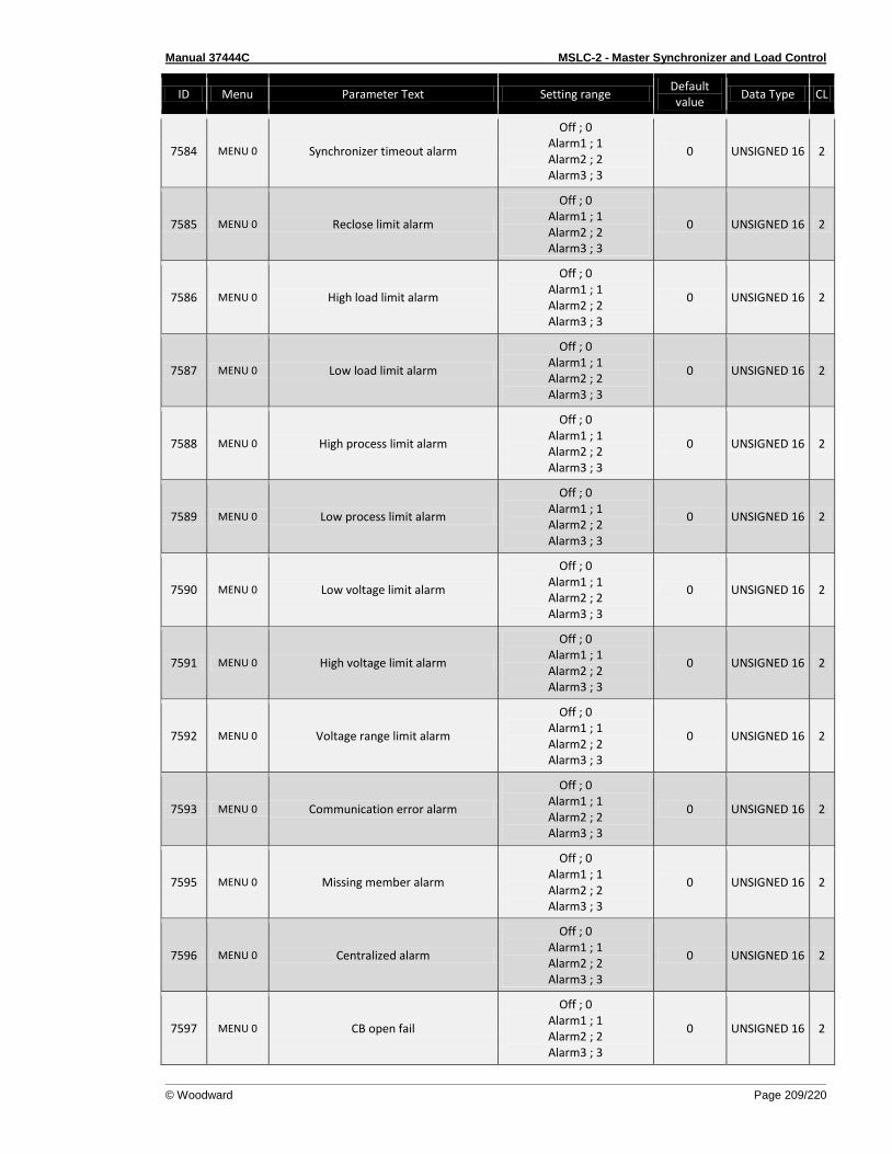
Manual 37444C MSLC-2 - Master Synchronizer and Load Control
© Woodward Page 209/220
ID Menu Parameter Text Setting range Default value
Data Type CL
7584 MENU 0 Synchronizer timeout alarm
Off ; 0 Alarm1 ; 1 Alarm2 ; 2 Alarm3 ; 3
0 UNSIGNED 16 2
7585 MENU 0 Reclose limit alarm
Off ; 0 Alarm1 ; 1 Alarm2 ; 2 Alarm3 ; 3
0 UNSIGNED 16 2
7586 MENU 0 High load limit alarm
Off ; 0 Alarm1 ; 1 Alarm2 ; 2 Alarm3 ; 3
0 UNSIGNED 16 2
7587 MENU 0 Low load limit alarm
Off ; 0 Alarm1 ; 1 Alarm2 ; 2 Alarm3 ; 3
0 UNSIGNED 16 2
7588 MENU 0 High process limit alarm
Off ; 0 Alarm1 ; 1 Alarm2 ; 2 Alarm3 ; 3
0 UNSIGNED 16 2
7589 MENU 0 Low process limit alarm
Off ; 0 Alarm1 ; 1 Alarm2 ; 2 Alarm3 ; 3
0 UNSIGNED 16 2
7590 MENU 0 Low voltage limit alarm
Off ; 0 Alarm1 ; 1 Alarm2 ; 2 Alarm3 ; 3
0 UNSIGNED 16 2
7591 MENU 0 High voltage limit alarm
Off ; 0 Alarm1 ; 1 Alarm2 ; 2 Alarm3 ; 3
0 UNSIGNED 16 2
7592 MENU 0 Voltage range limit alarm
Off ; 0 Alarm1 ; 1 Alarm2 ; 2 Alarm3 ; 3
0 UNSIGNED 16 2
7593 MENU 0 Communication error alarm
Off ; 0 Alarm1 ; 1 Alarm2 ; 2 Alarm3 ; 3
0 UNSIGNED 16 2
7595 MENU 0 Missing member alarm
Off ; 0 Alarm1 ; 1 Alarm2 ; 2 Alarm3 ; 3
0 UNSIGNED 16 2
7596 MENU 0 Centralized alarm
Off ; 0 Alarm1 ; 1 Alarm2 ; 2 Alarm3 ; 3
0 UNSIGNED 16 2
7597 MENU 0 CB open fail
Off ; 0 Alarm1 ; 1 Alarm2 ; 2 Alarm3 ; 3
0 UNSIGNED 16 2
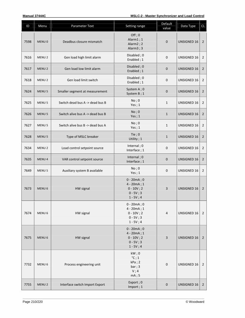
Manual 37444C MSLC-2 - Master Synchronizer and Load Control
Page 210/220 © Woodward
ID Menu Parameter Text Setting range Default value
Data Type CL
7598 MENU 0 Deadbus closure mismatch
Off ; 0 Alarm1 ; 1 Alarm2 ; 2 Alarm3 ; 3
0 UNSIGNED 16 2
7616 MENU 2 Gen load high limit alarm Disabled ; 0 Enabled ; 1
0 UNSIGNED 16 2
7617 MENU 2 Gen load low limit alarm Disabled ; 0 Enabled ; 1
0 UNSIGNED 16 2
7618 MENU 2 Gen load limit switch Disabled ; 0 Enabled ; 1
0 UNSIGNED 16 2
7624 MENU 5 Smaller segment at measurement System A ; 0 System B ; 1
0 UNSIGNED 16 2
7625 MENU 5 Switch dead bus A -> dead bus B No ; 0 Yes ; 1
1 UNSIGNED 16 2
7626 MENU 5 Switch alive bus A -> dead bus B No ; 0 Yes ; 1
1 UNSIGNED 16 2
7627 MENU 5 Switch alive bus B -> dead bus A No ; 0 Yes ; 1
1 UNSIGNED 16 2
7628 MENU 5 Type of MSLC breaker Tie ; 0
Utility ; 1 1 UNSIGNED 16 2
7634 MENU 2 Load control setpoint source Internal ; 0
Interface ; 1 0 UNSIGNED 16 2
7635 MENU 4 VAR control setpoint source Internal ; 0
Interface ; 1 0 UNSIGNED 16 2
7649 MENU 5 Auxiliary system B available No ; 0 Yes ; 1
0 UNSIGNED 16 2
7673 MENU 6 HW signal
0 - 20mA ; 0 4 - 20mA ; 1 0 - 10V ; 2 0 - 5V ; 3 1 - 5V ; 4
3 UNSIGNED 16 2
7674 MENU 6 HW signal
0 - 20mA ; 0 4 - 20mA ; 1 0 - 10V ; 2 0 - 5V ; 3 1 - 5V ; 4
4 UNSIGNED 16 2
7675 MENU 6 HW signal
0 - 20mA ; 0 4 - 20mA ; 1 0 - 10V ; 2 0 - 5V ; 3 1 - 5V ; 4
3 UNSIGNED 16 2
7732 MENU 6 Process engineering unit
kW ; 0 °C ; 1
kPa ; 2 bar ; 3 V ; 4
mA ; 5
0 UNSIGNED 16 2
7755 MENU 2 Interface switch Import Export Export ; 0 Import ; 1
0 UNSIGNED 16 2
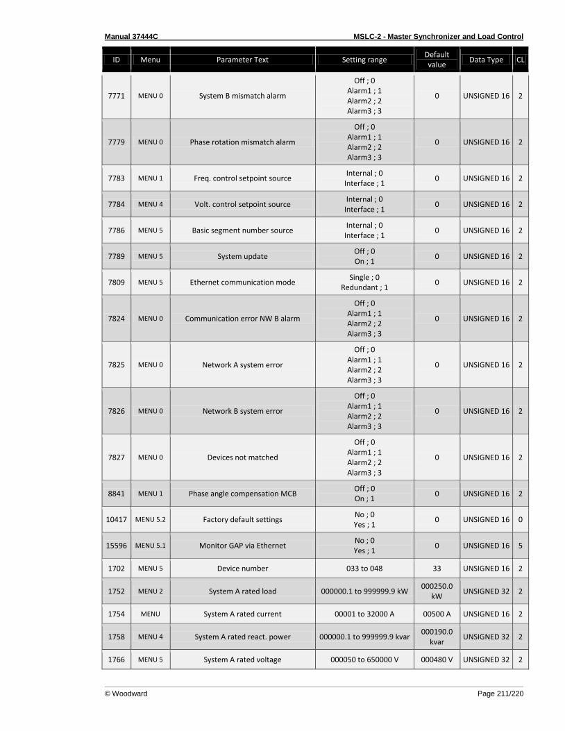
Manual 37444C MSLC-2 - Master Synchronizer and Load Control
© Woodward Page 211/220
ID Menu Parameter Text Setting range Default value
Data Type CL
7771 MENU 0 System B mismatch alarm
Off ; 0 Alarm1 ; 1 Alarm2 ; 2 Alarm3 ; 3
0 UNSIGNED 16 2
7779 MENU 0 Phase rotation mismatch alarm
Off ; 0 Alarm1 ; 1 Alarm2 ; 2 Alarm3 ; 3
0 UNSIGNED 16 2
7783 MENU 1 Freq. control setpoint source Internal ; 0
Interface ; 1 0 UNSIGNED 16 2
7784 MENU 4 Volt. control setpoint source Internal ; 0
Interface ; 1 0 UNSIGNED 16 2
7786 MENU 5 Basic segment number source Internal ; 0
Interface ; 1 0 UNSIGNED 16 2
7789 MENU 5 System update Off ; 0 On ; 1
0 UNSIGNED 16 2
7809 MENU 5 Ethernet communication mode Single ; 0
Redundant ; 1 0 UNSIGNED 16 2
7824 MENU 0 Communication error NW B alarm
Off ; 0 Alarm1 ; 1 Alarm2 ; 2 Alarm3 ; 3
0 UNSIGNED 16 2
7825 MENU 0 Network A system error
Off ; 0 Alarm1 ; 1 Alarm2 ; 2 Alarm3 ; 3
0 UNSIGNED 16 2
7826 MENU 0 Network B system error
Off ; 0 Alarm1 ; 1 Alarm2 ; 2 Alarm3 ; 3
0 UNSIGNED 16 2
7827 MENU 0 Devices not matched
Off ; 0 Alarm1 ; 1 Alarm2 ; 2 Alarm3 ; 3
0 UNSIGNED 16 2
8841 MENU 1 Phase angle compensation MCB Off ; 0 On ; 1
0 UNSIGNED 16 2
10417 MENU 5.2 Factory default settings No ; 0 Yes ; 1
0 UNSIGNED 16 0
15596 MENU 5.1 Monitor GAP via Ethernet No ; 0 Yes ; 1
0 UNSIGNED 16 5
1702 MENU 5 Device number 033 to 048 33 UNSIGNED 16 2
1752 MENU 2 System A rated load 000000.1 to 999999.9 kW 000250.0
kW UNSIGNED 32 2
1754 MENU System A rated current 00001 to 32000 A 00500 A UNSIGNED 16 2
1758 MENU 4 System A rated react. power 000000.1 to 999999.9 kvar 000190.0
kvar UNSIGNED 32 2
1766 MENU 5 System A rated voltage 000050 to 650000 V 000480 V UNSIGNED 32 2
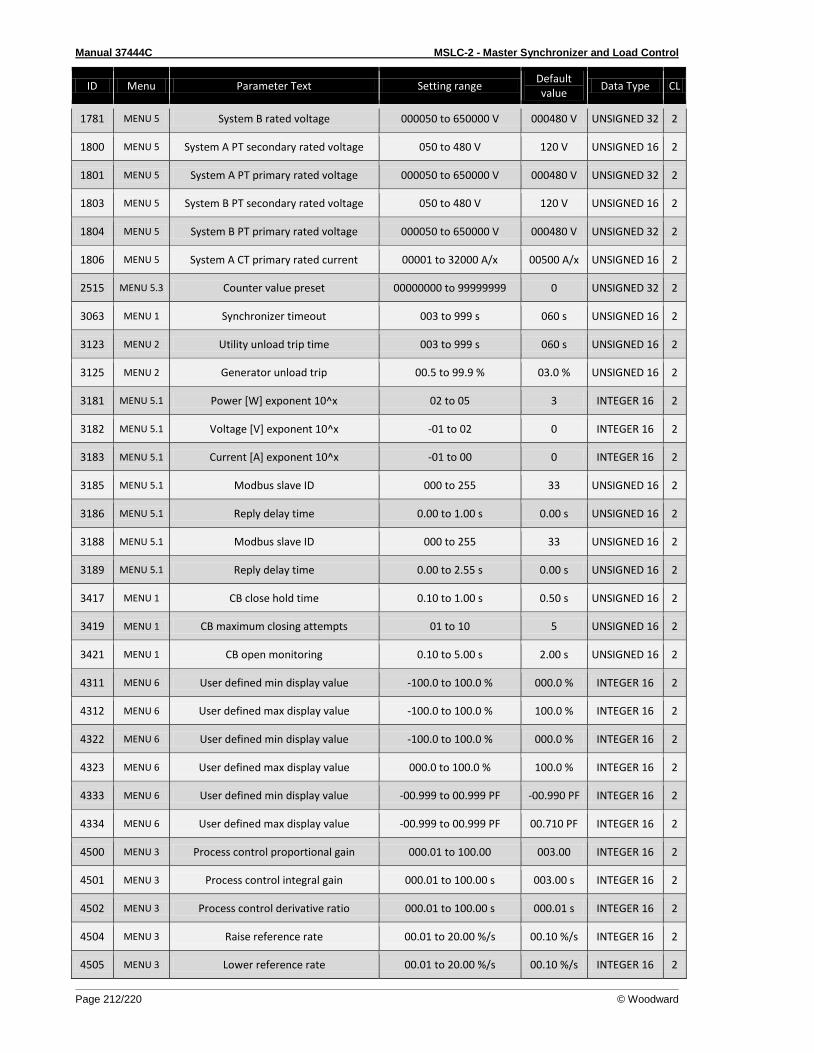
Manual 37444C MSLC-2 - Master Synchronizer and Load Control
Page 212/220 © Woodward
ID Menu Parameter Text Setting range Default value
Data Type CL
1781 MENU 5 System B rated voltage 000050 to 650000 V 000480 V UNSIGNED 32 2
1800 MENU 5 System A PT secondary rated voltage 050 to 480 V 120 V UNSIGNED 16 2
1801 MENU 5 System A PT primary rated voltage 000050 to 650000 V 000480 V UNSIGNED 32 2
1803 MENU 5 System B PT secondary rated voltage 050 to 480 V 120 V UNSIGNED 16 2
1804 MENU 5 System B PT primary rated voltage 000050 to 650000 V 000480 V UNSIGNED 32 2
1806 MENU 5 System A CT primary rated current 00001 to 32000 A/x 00500 A/x UNSIGNED 16 2
2515 MENU 5.3 Counter value preset 00000000 to 99999999 0 UNSIGNED 32 2
3063 MENU 1 Synchronizer timeout 003 to 999 s 060 s UNSIGNED 16 2
3123 MENU 2 Utility unload trip time 003 to 999 s 060 s UNSIGNED 16 2
3125 MENU 2 Generator unload trip 00.5 to 99.9 % 03.0 % UNSIGNED 16 2
3181 MENU 5.1 Power [W] exponent 10^x 02 to 05 3 INTEGER 16 2
3182 MENU 5.1 Voltage [V] exponent 10^x -01 to 02 0 INTEGER 16 2
3183 MENU 5.1 Current [A] exponent 10^x -01 to 00 0 INTEGER 16 2
3185 MENU 5.1 Modbus slave ID 000 to 255 33 UNSIGNED 16 2
3186 MENU 5.1 Reply delay time 0.00 to 1.00 s 0.00 s UNSIGNED 16 2
3188 MENU 5.1 Modbus slave ID 000 to 255 33 UNSIGNED 16 2
3189 MENU 5.1 Reply delay time 0.00 to 2.55 s 0.00 s UNSIGNED 16 2
3417 MENU 1 CB close hold time 0.10 to 1.00 s 0.50 s UNSIGNED 16 2
3419 MENU 1 CB maximum closing attempts 01 to 10 5 UNSIGNED 16 2
3421 MENU 1 CB open monitoring 0.10 to 5.00 s 2.00 s UNSIGNED 16 2
4311 MENU 6 User defined min display value -100.0 to 100.0 % 000.0 % INTEGER 16 2
4312 MENU 6 User defined max display value -100.0 to 100.0 % 100.0 % INTEGER 16 2
4322 MENU 6 User defined min display value -100.0 to 100.0 % 000.0 % INTEGER 16 2
4323 MENU 6 User defined max display value 000.0 to 100.0 % 100.0 % INTEGER 16 2
4333 MENU 6 User defined min display value -00.999 to 00.999 PF -00.990 PF INTEGER 16 2
4334 MENU 6 User defined max display value -00.999 to 00.999 PF 00.710 PF INTEGER 16 2
4500 MENU 3 Process control proportional gain 000.01 to 100.00 003.00 INTEGER 16 2
4501 MENU 3 Process control integral gain 000.01 to 100.00 s 003.00 s INTEGER 16 2
4502 MENU 3 Process control derivative ratio 000.01 to 100.00 s 000.01 s INTEGER 16 2
4504 MENU 3 Raise reference rate 00.01 to 20.00 %/s 00.10 %/s INTEGER 16 2
4505 MENU 3 Lower reference rate 00.01 to 20.00 %/s 00.10 %/s INTEGER 16 2
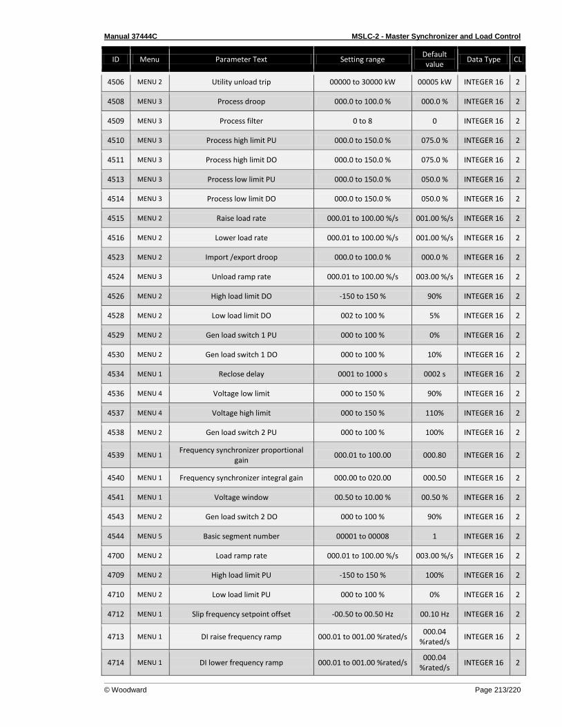
Manual 37444C MSLC-2 - Master Synchronizer and Load Control
© Woodward Page 213/220
ID Menu Parameter Text Setting range Default value
Data Type CL
4506 MENU 2 Utility unload trip 00000 to 30000 kW 00005 kW INTEGER 16 2
4508 MENU 3 Process droop 000.0 to 100.0 % 000.0 % INTEGER 16 2
4509 MENU 3 Process filter 0 to 8 0 INTEGER 16 2
4510 MENU 3 Process high limit PU 000.0 to 150.0 % 075.0 % INTEGER 16 2
4511 MENU 3 Process high limit DO 000.0 to 150.0 % 075.0 % INTEGER 16 2
4513 MENU 3 Process low limit PU 000.0 to 150.0 % 050.0 % INTEGER 16 2
4514 MENU 3 Process low limit DO 000.0 to 150.0 % 050.0 % INTEGER 16 2
4515 MENU 2 Raise load rate 000.01 to 100.00 %/s 001.00 %/s INTEGER 16 2
4516 MENU 2 Lower load rate 000.01 to 100.00 %/s 001.00 %/s INTEGER 16 2
4523 MENU 2 Import /export droop 000.0 to 100.0 % 000.0 % INTEGER 16 2
4524 MENU 3 Unload ramp rate 000.01 to 100.00 %/s 003.00 %/s INTEGER 16 2
4526 MENU 2 High load limit DO -150 to 150 % 90% INTEGER 16 2
4528 MENU 2 Low load limit DO 002 to 100 % 5% INTEGER 16 2
4529 MENU 2 Gen load switch 1 PU 000 to 100 % 0% INTEGER 16 2
4530 MENU 2 Gen load switch 1 DO 000 to 100 % 10% INTEGER 16 2
4534 MENU 1 Reclose delay 0001 to 1000 s 0002 s INTEGER 16 2
4536 MENU 4 Voltage low limit 000 to 150 % 90% INTEGER 16 2
4537 MENU 4 Voltage high limit 000 to 150 % 110% INTEGER 16 2
4538 MENU 2 Gen load switch 2 PU 000 to 100 % 100% INTEGER 16 2
4539 MENU 1 Frequency synchronizer proportional
gain 000.01 to 100.00 000.80 INTEGER 16 2
4540 MENU 1 Frequency synchronizer integral gain 000.00 to 020.00 000.50 INTEGER 16 2
4541 MENU 1 Voltage window 00.50 to 10.00 % 00.50 % INTEGER 16 2
4543 MENU 2 Gen load switch 2 DO 000 to 100 % 90% INTEGER 16 2
4544 MENU 5 Basic segment number 00001 to 00008 1 INTEGER 16 2
4700 MENU 2 Load ramp rate 000.01 to 100.00 %/s 003.00 %/s INTEGER 16 2
4709 MENU 2 High load limit PU -150 to 150 % 100% INTEGER 16 2
4710 MENU 2 Low load limit PU 000 to 100 % 0% INTEGER 16 2
4712 MENU 1 Slip frequency setpoint offset -00.50 to 00.50 Hz 00.10 Hz INTEGER 16 2
4713 MENU 1 DI raise frequency ramp 000.01 to 001.00 %rated/s 000.04
%rated/s INTEGER 16 2
4714 MENU 1 DI lower frequency ramp 000.01 to 001.00 %rated/s 000.04
%rated/s INTEGER 16 2
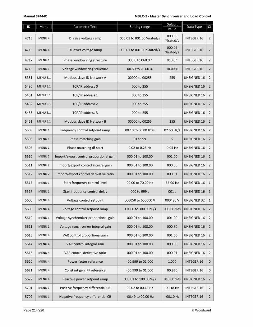
Manual 37444C MSLC-2 - Master Synchronizer and Load Control
Page 214/220 © Woodward
ID Menu Parameter Text Setting range Default value
Data Type CL
4715 MENU 4 DI raise voltage ramp 000.01 to 001.00 %rated/s 000.05
%rated/s INTEGER 16 2
4716 MENU 4 DI lower voltage ramp 000.01 to 001.00 %rated/s 000.05
%rated/s INTEGER 16 2
4717 MENU 1 Phase window ring structure 000.0 to 060.0 ° 010.0 ° INTEGER 16 2
4718 MENU 1 Voltage window ring structure 00.50 to 20.00 % 10.00 % INTEGER 16 2
5351 MENU 5.1 Modbus slave ID Network A 00000 to 00255 255 UNSIGNED 16 2
5430 MENU 5.1 TCP/IP address 0 000 to 255 UNSIGNED 16 2
5431 MENU 5.1 TCP/IP address 1 000 to 255 UNSIGNED 16 2
5432 MENU 5.1 TCP/IP address 2 000 to 255 UNSIGNED 16 2
5433 MENU 5.1 TCP/IP address 3 000 to 255 UNSIGNED 16 2
5451 MENU 5.1 Modbus slave ID Network B 00000 to 00255 255 UNSIGNED 16 2
5503 MENU 1 Frequency control setpoint ramp 00.10 to 60.00 Hz/s 02.50 Hz/s UNSIGNED 16 2
5505 MENU 1 Phase matching gain 01 to 99 5 UNSIGNED 16 2
5506 MENU 1 Phase matching df-start 0.02 to 0.25 Hz 0.05 Hz UNSIGNED 16 2
5510 MENU 2 Import/export control proportional gain 000.01 to 100.00 001.00 UNSIGNED 16 2
5511 MENU 2 Import/export control integral gain 000.01 to 100.00 000.50 UNSIGNED 16 2
5512 MENU 2 Import/export control derivative ratio 000.01 to 100.00 000.01 UNSIGNED 16 2
5516 MENU 1 Start frequency control level 00.00 to 70.00 Hz 55.00 Hz UNSIGNED 16 1
5517 MENU 1 Start frequency control delay 000 to 999 s 001 s UNSIGNED 16 1
5600 MENU 4 Voltage control setpoint 000050 to 650000 V 000480 V UNSIGNED 32 1
5603 MENU 4 Voltage control setpoint ramp 001.00 to 300.00 %/s 005.00 %/s UNSIGNED 16 2
5610 MENU 1 Voltage synchronizer proportional gain 000.01 to 100.00 001.00 UNSIGNED 16 2
5611 MENU 1 Voltage synchronizer integral gain 000.01 to 100.00 000.50 UNSIGNED 16 2
5613 MENU 4 VAR control proportional gain 000.01 to 100.00 001.00 UNSIGNED 16 2
5614 MENU 4 VAR control integral gain 000.01 to 100.00 000.50 UNSIGNED 16 2
5615 MENU 4 VAR control derivative ratio 000.01 to 100.00 000.01 UNSIGNED 16 2
5620 MENU 4 Power factor reference -00.999 to 01.000 1,000 INTEGER 16 0
5621 MENU 4 Constant gen. PF reference -00.999 to 01.000 00.950 INTEGER 16 0
5622 MENU 4 Reactive power setpoint ramp 000.01 to 100.00 %/s 010.00 %/s UNSIGNED 16 2
5701 MENU 1 Positive frequency differential CB 00.02 to 00.49 Hz 00.18 Hz INTEGER 16 2
5702 MENU 1 Negative frequency differential CB -00.49 to 00.00 Hz -00.10 Hz INTEGER 16 2
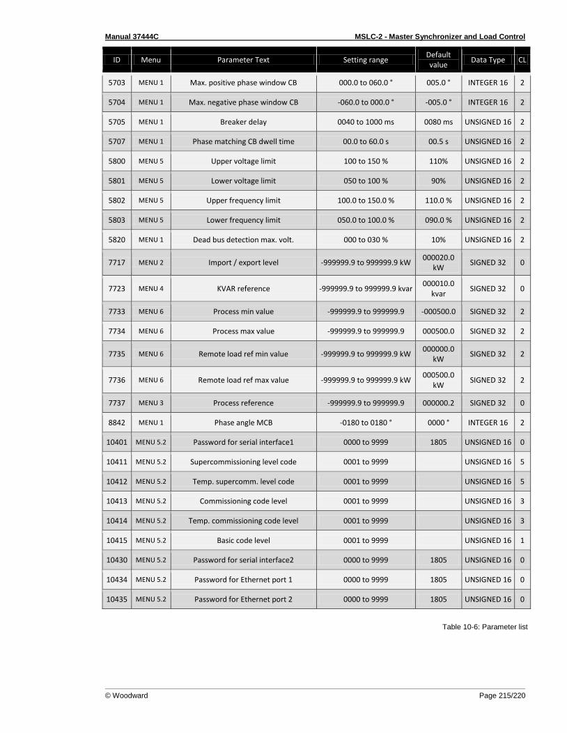
Manual 37444C MSLC-2 - Master Synchronizer and Load Control
© Woodward Page 215/220
ID Menu Parameter Text Setting range Default value
Data Type CL
5703 MENU 1 Max. positive phase window CB 000.0 to 060.0 ° 005.0 ° INTEGER 16 2
5704 MENU 1 Max. negative phase window CB -060.0 to 000.0 ° -005.0 ° INTEGER 16 2
5705 MENU 1 Breaker delay 0040 to 1000 ms 0080 ms UNSIGNED 16 2
5707 MENU 1 Phase matching CB dwell time 00.0 to 60.0 s 00.5 s UNSIGNED 16 2
5800 MENU 5 Upper voltage limit 100 to 150 % 110% UNSIGNED 16 2
5801 MENU 5 Lower voltage limit 050 to 100 % 90% UNSIGNED 16 2
5802 MENU 5 Upper frequency limit 100.0 to 150.0 % 110.0 % UNSIGNED 16 2
5803 MENU 5 Lower frequency limit 050.0 to 100.0 % 090.0 % UNSIGNED 16 2
5820 MENU 1 Dead bus detection max. volt. 000 to 030 % 10% UNSIGNED 16 2
7717 MENU 2 Import / export level -999999.9 to 999999.9 kW 000020.0
kW SIGNED 32 0
7723 MENU 4 KVAR reference -999999.9 to 999999.9 kvar 000010.0
kvar SIGNED 32 0
7733 MENU 6 Process min value -999999.9 to 999999.9 -000500.0 SIGNED 32 2
7734 MENU 6 Process max value -999999.9 to 999999.9 000500.0 SIGNED 32 2
7735 MENU 6 Remote load ref min value -999999.9 to 999999.9 kW 000000.0
kW SIGNED 32 2
7736 MENU 6 Remote load ref max value -999999.9 to 999999.9 kW 000500.0
kW SIGNED 32 2
7737 MENU 3 Process reference -999999.9 to 999999.9 000000.2 SIGNED 32 0
8842 MENU 1 Phase angle MCB -0180 to 0180 ° 0000 ° INTEGER 16 2
10401 MENU 5.2 Password for serial interface1 0000 to 9999 1805 UNSIGNED 16 0
10411 MENU 5.2 Supercommissioning level code 0001 to 9999 UNSIGNED 16 5
10412 MENU 5.2 Temp. supercomm. level code 0001 to 9999 UNSIGNED 16 5
10413 MENU 5.2 Commissioning code level 0001 to 9999 UNSIGNED 16 3
10414 MENU 5.2 Temp. commissioning code level 0001 to 9999 UNSIGNED 16 3
10415 MENU 5.2 Basic code level 0001 to 9999 UNSIGNED 16 1
10430 MENU 5.2 Password for serial interface2 0000 to 9999 1805 UNSIGNED 16 0
10434 MENU 5.2 Password for Ethernet port 1 0000 to 9999 1805 UNSIGNED 16 0
10435 MENU 5.2 Password for Ethernet port 2 0000 to 9999 1805 UNSIGNED 16 0
Table 10-6: Parameter list

Manual 37444C MSLC-2 - Master Synchronizer and Load Control
Page 216/220 © Woodward
Appendix G. Service Options
Product Service Options
≡≡≡≡≡≡≡≡≡≡≡≡≡≡≡≡≡≡≡≡≡≡≡≡≡ The following factory options are available for servicing Woodward equipment, based on the standard Woodward Product and Service Warranty (5-01-1205) that is in effect at the time the product is pur-chased from Woodward or the service is performed. If you are experiencing problems with installation or unsatisfactory performance of an installed system, the following options are available:
Consult the troubleshooting guide in the manual.
Contact Woodward technical assistance (see "How to Contact Woodward" later in this chapter) and discuss your problem. In most cases, your problem can be resolved over the phone. If not, you can select which course of action you wish to pursue based on the available services listed in this section.
Returning Equipment for Repair
≡≡≡≡≡≡≡≡≡≡≡≡≡≡≡≡≡≡≡≡≡≡≡≡≡ If a control (or any part of an electronic control) is to be returned to Woodward for repair, please con-tact Woodward in advance to obtain a Return Authorization Number. When shipping the unit(s), attach a tag with the following information:
name and location where the control is installed;
name and phone number of contact person;
complete Woodward part numbers (P/N) and serial number (S/N);
description of the problem;
instructions describing the desired type of repair.
CAUTION To prevent damage to electronic components caused by improper handling, read and observe the pre-cautions in Woodward manual 82715, Guide for Handling and Protection of Electronic Controls, Printed Circuit Boards and Modules.

Manual 37444C MSLC-2 - Master Synchronizer and Load Control
© Woodward Page 217/220
Packing a Control Use the following materials when returning a complete control:
protective caps on any connectors;
antistatic protective bags on all electronic modules;
packing materials that will not damage the surface of the unit;
at least 100 mm (4 inches) of tightly packed, industry-approved packing material;
a packing carton with double walls;
a strong tape around the outside of the carton for increased strength.
Return Authorization Number RAN Please call by phone our Customer Service Department in Stuttgart [+49 (0) 711 789 54-510]. They will help expedite the processing of your order through our distributors or local service facility. To expedite the repair process, contact Woodward in advance to obtain a Return Authorization Number and ar-range for issue of a purchase order for the unit(s) to be repaired. No work can be started until a pur-chase order is received.
NOTE We highly recommend that you make arrangement in advance for return shipments. Contact a Woodward customer service representative at +49 (0) 711 789 54-0 for instructions and for a Re-turn Authorization Number.
Replacement Parts
≡≡≡≡≡≡≡≡≡≡≡≡≡≡≡≡≡≡≡≡≡≡≡≡≡ When ordering replacement parts for controls, include the following information:
the part numbers P/N (XXXX-XXX) that is on the enclosure nameplate;
the unit serial number S/N, which is also on the nameplate.

Manual 37444C MSLC-2 - Master Synchronizer and Load Control
Page 218/220 © Woodward
How to Contact Woodward
≡≡≡≡≡≡≡≡≡≡≡≡≡≡≡≡≡≡≡≡≡≡≡≡≡ Please contact following address if you have questions or if you want to send a product for repair: Woodward GmbH Handwerkstrasse 29 70565 Stuttgart - Germany Phone: +49 (0) 711 789 54-510 (8.00 - 16.30 German time) Fax: +49 (0) 711 789 54-101 e-mail: [email protected] For assistance outside Germany please contact the Woodward Customer Service Department or con-sult our worldwide directory on Woodward’s website (www.woodward.com) for the name of your nearest Woodward distributor or service facility. For worldwide directory information, go to www.woodward.com/locations.
Engineering Services
≡≡≡≡≡≡≡≡≡≡≡≡≡≡≡≡≡≡≡≡≡≡≡≡≡ Woodward Industrial Controls Engineering Services offers the following after-sales support for Wood-ward products. For these services, you can contact us by telephone, by e-mail, or through the Wood-ward website.
Technical support
Product training
Field service during commissioning Technical Support is available through our many worldwide locations or through our authorized dis-tributors depending on the product. This service can assist you with technical questions or problem solving during normal business hours. Emergency assistance is also available during non-business hours by phoning our toll-free number and stating the urgency of your problem. For technical engineer-ing support, please contact us via our local phone numbers, e-mail us, or use our website and refer-ence technical support. Product Training is available on-site from several of our worldwide facilities. This training, conducted by experienced personnel, will assure that you will be able to maintain system reliability and availabil-ity. For information concerning training, please contact us via our local phone numbers, e-mail us, or use our website and reference customer training. Field Service engineering on-site support is available, depending on the product and location, from our facility in Colorado, or from one of many worldwide Woodward offices or authorized distributors. Field engineers are experienced on both Woodward products as well as on much of the non-Woodward equipment with which our products interface. For field service engineering assistance, please contact us via our toll-free or local phone numbers, e-mail us, or use our website and reference field service.

Manual 37444C MSLC-2 - Master Synchronizer and Load Control
© Woodward Page 219/220
Technical Assistance
≡≡≡≡≡≡≡≡≡≡≡≡≡≡≡≡≡≡≡≡≡≡≡≡≡ If you need to telephone for technical assistance, you will need to provide the following information. Please write it down here before phoning:
Contact Your company _____________________________________________ Your name ________________________________________________ Phone number _____________________________________________ Fax number _______________________________________________ Control (see name plate) Unit no. and revision: P/N: _________________ REV: ___________ Unit type ______________________________________ Serial number S/N ___________________________________ Description of your problem _________________________________________________________ _________________________________________________________ _________________________________________________________ _________________________________________________________ _________________________________________________________ _________________________________________________________ Please be sure you have a list of all parameters available. You can print this using ToolKit. Additionally you can save the complete set of parameters (standard values) and send them to our Service depart-ment via e-mail.
We appreciate your comments about the content of our publications.
Please send comments to: [email protected]
Please include the manual number from the front cover of this publication.
Woodward GmbH Handwerkstrasse 29 - 70565 Stuttgart - Germany
Phone +49 (0) 711 789 54-510 Fax +49 (0) 711 789 54-101 [email protected]
Homepage
http://www.woodward.com
Woodward has company-owned plants, subsidiaries and branches, as well as authorized distributors and other authorized service and sales facilities throughout the world.
Complete address/phone/fax/e-mail information
for all locations is available on our website (www.woodward.com).
2014/07/Stuttgart