master-slave communication with modbus rtu protocol for s7 …... · 2020-02-10 · legal...
TRANSCRIPT

Master-Slave Communication with Modbus RTU Protocol for S7-200 SMART
S7 - 200 SMART/ Version 2.3
https://w3.siemens.co.in/automation/in/en/automation-systems/industrial-automation/s7-200-smart-plc/pages/default.aspx
Siemens
Industry
Online
Support

Legal information
S7-200 SMART Modbus RTU Communication Entry-ID:1, V0.0, 06/2019 2
S
iem
en
s A
G C
op
yri
gh
t yea
r A
ll ri
gh
ts r
ese
rve
d
Legal information
Use of application examples
Application examples illustrate the solution of automation tasks through an interaction of several components in the form of text, graphics and/or software modules. The application examples are a free service by Siemens AG and/or a subsidiary of Siemens AG ("Siemens"). They are non-binding and make no claim to completeness or functionality regarding configuration and equipment. The application examples merely offer help with typical tasks; they do not constitute customer-specific solutions. You yourself are responsible for the proper and safe operation of the products in accordance with applicable regulations and must also check the function of the respective application example and customize it for your system.
Siemens grants you the non-exclusive, non-sub licensable and non-transferable right to have the application examples used by technically trained personnel. Any change to the application examples is your responsibility. Sharing the application examples with third parties or copying the application examples or excerpts thereof is permitted only in combination with your own products. The application examples are not required to undergo the customary tests and quality inspections of a chargeable product; they may have functional and performance defects as well as errors. It is your responsibility to use them in such a manner that any malfunctions that may occur do not result in property damage or injury to persons.
Disclaimer of liability
Siemens shall not assume any liability, for any legal reason whatsoever, including, without limitation, liability for the usability, availability, completeness and freedom from defects of the application examples as well as for related information, configuration and performance data and any damage caused thereby. This shall not apply in cases of mandatory liability, for example under the German Product Liability Act, or in cases of intent, gross negligence, or culpable loss of life, bodily injury or damage to health, non-compliance with a guarantee, fraudulent non-disclosure of a defect, or culpable breach of material contractual obligations. Claims for damages arising from a breach of material contractual obligations shall however be limited to the foreseeable damage typical of the type of agreement, unless liability arises from intent or gross negligence or is based on loss of life, bodily injury or damage to health. The foregoing provisions do not imply any change in the burden of proof to your detriment. You shall indemnify Siemens against existing or future claims of third parties in this connection except where Siemens is mandatorily liable.
By using the application examples you acknowledge that Siemens cannot be held liable for any damage beyond the liability provisions described.
Other information
Siemens reserves the right to make changes to the application examples at any time without notice. In case of discrepancies between the suggestions in the application examples and other Siemens publications such as catalogs, the content of the other documentation shall have precedence.
The Siemens terms of use (https://support.industry.siemens.com) shall also apply.
Security information
Siemens provides products and solutions with Industrial Security functions that support the secure operation of plants, systems, machines and networks.
In order to protect plants, systems, machines and networks against cyber threats, it is necessary to implement – and continuously maintain – a holistic, state-of-the-art industrial security concept. Siemens’ products and solutions constitute one element of such a concept.
Customers are responsible for preventing unauthorized access to their plants, systems, machines and networks. Such systems, machines and components should only be connected to an

Legal information
S7-200 SMART Modbus RTU Communication Entry-ID:1, V0.0, 06/2019 3
S
iem
en
s A
G C
op
yri
gh
t yea
r A
ll ri
gh
ts r
ese
rve
d
enterprise network or the Internet if and to the extent such a connection is necessary and only when appropriate security measures (e.g. firewalls and/or network segmentation) are in place.
For additional information on industrial security measures that may be implemented, please visit https://www.siemens.com/industrialsecurity.
Siemens’ products and solutions undergo continuous development to make them more secure. Siemens strongly recommends that product updates are applied as soon as they are available and that the latest product versions are used. Use of product versions that are no longer supported, and failure to apply the latest updates may increase customer’s exposure to cyber threats.
To stay informed about product updates, subscribe to the Siemens Industrial Security RSS Feed at: https://www.siemens.com/industrialsecurity.

Table of contents
S7-200 SMART Modbus RTU Communication Entry-ID:1, V0.0, 06/2019 4
S
iem
en
s A
G C
op
yri
gh
t yea
r A
ll ri
gh
ts r
ese
rve
d
Table of contents
Warranty and liability ................................................................................................... 2
1 Introduction ........................................................................................................ 5
1.1 Overview............................................................................................... 5
1.2 Mode of operation ................................................................................ 5
1.3 Components used ................................................................................ 6
2 Engineering ........................................................................................................ 7
2.1 Hardware setup .................................................................................... 7
2.2 Communication and Connection Port .................................................. 8
3 Engineering ...................................................................................................... 12
3.1 Description of interface ....................................................................... 12
3.2 Project integration .............................................................................. 13
3.3 Operation ............................................................................................ 21
3.4 Error handling ..................................................................................... 27
4 Additional information .................................................................................... 29
5 Appendix .......................................................................................................... 31
5.1 Service and Support ........................................................................... 31
5.2 Support .............................................................................................. 32
5.3 Links and Literature ............................................................................ 32
5.4 Change documentation ...................................................................... 32

1 Introduction
S7-200 SMART Modbus RTU Communication Entry-ID:1, V0.0, 06/2019 5
S
iem
en
s A
G C
op
yri
gh
t yea
r A
ll ri
gh
ts r
ese
rve
d
1 Introduction
1.1 Overview
Modbus is a public communication protocol, and its simplest serial communication part
only specifies the basic data transmission format on the serial line. In the OSI seven-layer
protocol model, only one or two layers are used.
Modbus has two serial transfer modes, ASCII and RTU. They define different ways in which
data is packed and decoded. Devices that support the Modbus protocol generally support the
RTU format.
Both parties to the communication must support one of the above modes.Modbus is a
master/slave communication mode for a single master. There can only be one master station on
the Modbus network. The master station has no address on the Modbus network. The slave
address range is 0 - 247, where 0 is the broadcast address and the slave's actual address
range is 1 - 247.
Modbus communication standard protocols can be transmitted by various transmission
methods, such as RS232C, RS485, optical fiber, radio, etc. The RS485 half-duplex
communication is implemented on the S7-200 CPU communication port, using the free port
function of the S7-200 SMART.
For detailed protocols and specifications, please visit the Modbus organization's website:
http://www.modbus.org
1.2 Mode of operation
The Modbus communication protocol is implemented in the free port mode of the S7-
200 SMART CPU communication port, and can be transmitted through a slow communication
device such as a wireless data station. This facilitates the formation of a simple wireless
communication network between the S7-200 SMART.
Please refer to the S7-200 SMART System Manual for details.

1 Introduction
S7-200 SMART Modbus RTU Communication Entry-ID:1, V0.0, 06/2019 6
S
iem
en
s A
G C
op
yri
gh
t yea
r A
ll ri
gh
ts r
ese
rve
d
1.3 Components used
This application example has been created with the following hardware and software components:
Table 1-1
Component Number Article number Note
CPU ST60 3 6ES7-288-1ST60-0AA0
CPU ST40 2 6ES7-288-1ST40-0AA0
CPU ST30 2 6ES7-288-1ST30-0AA0
CPU ST20 2 6ES7-288-1ST20-0AA0
SB CM01 9 6SE7-288-5CM01-0AA0
S7 MICROWIN SMART V2.4
1 6ES7 288-SW01-0AA0
This application example consists of the following components:
Table 1-2
Component File name Note

2 Engineering
S7-200 SMART Modbus RTU Communication Entry-ID:1, V0.0, 06/2019 7
S
iem
en
s A
G C
op
yri
gh
t yea
r A
ll ri
gh
ts r
ese
rve
d
2 Engineering
2.1 Hardware setup

2 Engineering
S7-200 SMART Modbus RTU Communication Entry-ID:1, V0.0, 06/2019 8
S
iem
en
s A
G C
op
yri
gh
t yea
r A
ll ri
gh
ts r
ese
rve
d
2.2 Communication Port and Connection Method
Standard type of S7-200 SMART CPU provides one Ethernet port and one RS485 port (port 0), the standard CPU additionally supports the SB CM01 signal board (port 1), and the signal board can be configured with STEP 7-Micro/WIN SMART software It is an RS232 communication port or an RS485 communication port.
2.2.1 Ethernet Port Connection
The Ethernet port of the S7-200 SMART CPU has two network connection methods:
Direct connection and Indirect connection.
Direct Connection:
When an S7-200 SMART CPU communicates with a programming device, HMI or
another S7-200 SMART CPU, a direct connection is achieved. Direct connection does not
require the use of a switch, and the two devices can be directly connected using a network
cable, as shown in Figure 2. Direct connection of the communication device.
Indirect Connection:
When more than two communication devices are communicating, a switch is required to
implement the network connection. You can connect multiple CPUs and HMI devices using the
rail-mounted Siemens CSM1277 4-port switch, as shown in Figure 3. Network connections for
multiple communication devices.

2 Engineering
S7-200 SMART Modbus RTU Communication Entry-ID:1, V0.0, 06/2019 9
S
iem
en
s A
G C
op
yri
gh
t yea
r A
ll ri
gh
ts r
ese
rve
d
2.2.2 RS485 Network Connection
The S7-200 SMART CPU's integrated RS485 communication port (port 0) is an RS485
compatible 9-pin D-type connector. The pin assignments for the CPU-integrated RS485
communication port.
Table 1. Pin Assignments for the Integrated RS485 Port of the S7-200 SMART CPU
Connector Pin
label signal Pin definition
1 shield Chassis ground
2 24V back Logical common
3 RS-485 signal B RS-485 signal B
4 Send request RTS (TTL)
5 5V back Logical common
6 + 5V +5 V, 100 Ω series resistor
7 +24V +24 V
8 RS-485 signal A RS-485 signal A
9 Not applicable 10-bit protocol selection
(input)
shell shield Chassis ground

2 Engineering
S7-200 SMART Modbus RTU Communication Entry-ID:1, V0.0, 06/2019 10
S
iem
en
s A
G C
op
yri
gh
t yea
r A
ll ri
gh
ts r
ese
rve
d
Biasing and terminating the network cable
Siemens provides two types of network connectors that you can use to easily connect
multiple devices to a network:
Standard network connector.
Connector that includes a port which allows you to connect an HMI device to the
network without disturbing any existing network connections.
The programming port connector passes all signals (including the power pins) from the
S7-200 SMART CPU through to the programming port, which is especially useful for connecting
devices that draw power from the S7-200 SMART CPU (such as a TD 400C).
Both connectors have two sets of terminal screws to allow you to attach the incoming
and outgoing network cables. Both connectors also have switches to bias and terminate the
network selectively. The following shows typical biasing and termination for the cable
connectors.
Table: Biasing and termination for cable connectors
Cable must be terminated and biased at both ends. Bare shielding: Approximately 12 mm (1/2 in) must contact the metal guides of all locations.
1. Switch position = On: Terminated and biased
2. Switch position = Off: No termination or bias
3. Switch position = On: Terminated and biased
Table: Termination and bias switch positions
Switch position = On: Termination and biased Switch position = Off: No termination or bias
1. Pin number
2. Network connector
3. Cable shield

2 Engineering
S7-200 SMART Modbus RTU Communication Entry-ID:1, V0.0, 06/2019 11
S
iem
en
s A
G C
op
yri
gh
t yea
r A
ll ri
gh
ts r
ese
rve
d
2.2.3 SB CM01 Signal Board Connection
The standard CPU additionally supports the SB CM01 signal board, which can be
configured as an RS485 communication port or an RS232 communication port with STEP 7-
Micro/WIN SMART software.
Table 2. Pin Assignment Table for S7-200 SMART SB CM01 Signal Board Port (Port 1)
Connector Pin label signal Pin definition
1 Ground Chassis ground
2 Tx/B RS232-Tx/RS485-B
3 send request RTS (TTL)
4 M ground Logical common
5 Rx/A RS232-Rx/RS485-A
6 + 5V +5 V, 100 Ω series resistor
Biasing and terminating the CM01 signal board
You can use the CM01 signal board to easily connect multiple devices to a network.
The signal board passes all signals (including the power pins) from the S7-200 SMART CPU
through to the programming port, which is especially useful for connecting devices that draw
power from the S7-200 SMART CPU (such as a TD 400C).
1. Terminal name
2. Terminal block
3. Cable shield

3 Engineering
S7-200 SMART Modbus RTU Communication Entry-ID:1, V0.0, 06/2019 12
S
iem
en
s A
G C
op
yri
gh
t yea
r A
ll ri
gh
ts r
ese
rve
d
3 Engineering
3.1 Description of interface The Modbus communication protocol is implemented in the free port mode of the S7-
200 SMART CPU communication port, and can be transmitted through a slow communication
device. This facilitates the formation of a simple communication network between the S7-200
SMART.
Siemens officially launched the Modbus RTU Master Base Protocol Library (Siemens Standard
Library Instructions) in STEP 7-Micro/WIN SMART.
Figure 1. Siemens Standard Instruction Library (STEP 7-Micro/WIN SMART)
Note :
1. The function of the Modbus RTU master station library is realized by calling the pre-
programmed program function block in the user program. The library is valid for
the CPU integrated RS 485 communication port and CM 01 signal board. The library will set the
communication port to work in free port mode.
2. The Modbus RTU master station instruction library uses some user interrupt functions which
are locked. It is not allowed to disable interrupts in the user program when programming other
programs.

3 Engineering
S7-200 SMART Modbus RTU Communication Entry-ID:1, V0.0, 06/2019 13
S
iem
en
s A
G C
op
yri
gh
t yea
r A
ll ri
gh
ts r
ese
rve
d
3.2 Project integration
1. Call the Modbus RTU master initialization and control subroutine.
Figure 2. Siemens Standard Instruction Library (STEP 7-Micro/WIN SMART)
Use SM0.0(ALWAYS_ON) to call MBUS_CTRL to complete the initialization of the master and
start its function control:
Figure 3. Calling Modbus RTU master initialization and control subroutine with
SM0.0(ALWAYS_ON)

3 Engineering
S7-200 SMART Modbus RTU Communication Entry-ID:1, V0.0, 06/2019 14
S
iem
en
s A
G C
op
yri
gh
t yea
r A
ll ri
gh
ts r
ese
rve
d
The meaning of each parameter is as follows:
a. EN Enable: Must ensure that each scan cycle is enabled (using SM0.0(ALWAYS_ON))
b. Mode mode: When 1 is enabled, the Modbus protocol function is enabled; when 0, the system is restored to the system PPI protocol.
c. Baud Baud rate: The supported communication baud rates are 1200, 2400, 4800, 9600, 19200, 38400, 57600, 115200.
d. Parity check: Calibration method selection
0=no parity
1= odd test
2 = even test
e. Port The port number:
0 = CPU integrated RS 485 communication port; 1 = Optional CM 01 signal board.
f. Timeout time out:
The time the master waits for a response from the slave, in milliseconds. A typical setting is 1000 milliseconds (1 second), and the allowed range is 1 - 32767.
Note: This value must be set large enough to ensure that the slave has a time response.
g. Done Completion bit:
This bit is automatically set to 1 when initialization is complete. This bit can be used to initiate MBUS_MSG read and write operations (see the routine)
h. Error
Initialization error code (valid only when the Done bit is 1):
2. Call the Modbus RTU master read/write subroutine MBUS_MSG to send a Modbus request.
Figure 4. Calling the Modbus RTU master read and write subroutine

3 Engineering
S7-200 SMART Modbus RTU Communication Entry-ID:1, V0.0, 06/2019 15
S
iem
en
s A
G C
op
yri
gh
t yea
r A
ll ri
gh
ts r
ese
rve
d
The meaning of each parameter is as follows:
a. EN Enable: Only one read/write function (ie MBUS_MSG) can be enabled at a time.
Note: It is recommended that each read/write function (ie MBUS_MSG) be activated with the Done Completion bit of the previous MBUS_MSG instruction to ensure that all read and write instructions are looped (see routine).
b. First Read & write request bits:
Each new read and write request must use a pulse trigger
c. Slave Slave address: Selectable range 1 - 247
d. RW Read & write requests:
0 = read, 1 = write
note:
1. The digital output and holding registers support read and write functions.
2. The digital input and analog input only support the read function.
e. Addr Read & write slave
Select the type of data to read and write
Data address: 00001 to 0xxxx - digital output
10001 to 1xxxx - digital input
30001 to 3xxxx - analog input
40001 to 4xxxx - holding registers
f. Count Number of data
Number of data to be communicated (number of bits or words)
Note: The maximum amount of data that can be read/written by the Modbus master is 120 words (refer to each MBUS_MSG instruction)
g. DataPtr Data pointer: 1. If it is a read command, the read data is placed in this data area.
2. If it is a write command, the data to be written is placed in this data area.
h. Done Completion bit Read and write function completion bit
i. Error Error code: The error code is valid only when the Done bit is 1.

3 Engineering
S7-200 SMART Modbus RTU Communication Entry-ID:1, V0.0, 06/2019 16
S
iem
en
s A
G C
op
yri
gh
t yea
r A
ll ri
gh
ts r
ese
rve
d
3. Open New Microwin Smart project for Slave programming.
Check the Micro/WIN SMART Modbus RTU slave instruction library .The library should include
two subroutines MBUS_INIT and MBUS_SLAVE.
Figure 5. Library instructions in the instruction tree
4. When programming, use SM0.1 to call the subroutine MBUS_INIT for initialization, use
SM0.0(ALWAYS_ON) to call MBUS_SLAVE, and specify the corresponding parameters. Detail
description can be found in local variable table of the subroutine.
Figure 6. Call Modbus RTU communication command library

3 Engineering
S7-200 SMART Modbus RTU Communication Entry-ID:1, V0.0, 06/2019 17
S
iem
en
s A
G C
op
yri
gh
t yea
r A
ll ri
gh
ts r
ese
rve
d
The meaning of each parameter is as follows:
a. Mode Mode: When 1 is enabled, the Modbus protocol function is enabled; when 0, the system is restored to the system PPI protocol.
b. Slave Address
Address Modbus slave address, value 1~247
c. Baud Baud rate: The supported communication baud rates are 1200, 2400, 4800, 9600, 19200, 38400, 57600, 115200.
d. Parity check: Calibration method selection
0=no parity
1= odd test
2 = even test
e. Port The port number:
0 = CPU integrated RS 485 communication port; 1 = Optional CM 01 signal board.
f. Delay Delay: Additional inter-character delay, default is 0
g. Max AQ Maximum I/Q bit:
The maximum number of I/O points to participate in communication. The I/O image area of the S7-200 SMART is 256/256 (but currently only up to 4 expansion modules can be connected, so the maximum number of I/O points is 188 at present) /188)
h. MAX AI Maximum AI words:
The maximum number of AI channels participating in communication, up to 56
i. MaxHold
Maximum holding register area:
The time the master waits for a response from the slave, in milliseconds. A typical setting is 1000 milliseconds (1 second), and the allowed range is 1 - 32767.
j. HoldStart
Keep register area start address:
Specified by “&VBx“ (indirect addressing mode)
k. Done Completion bit:
Set after successful initialization
l. Error Initialization error code
m. Done Completion bit:
This bit is automatically set to 1 when initialization is complete. This bit can be used to initiate MBUS_MSG read and write operations (see the routine)
n. Error
Initialization error code (valid only when the Done bit is 1)

3 Engineering
S7-200 SMART Modbus RTU Communication Entry-ID:1, V0.0, 06/2019 18
S
iem
en
s A
G C
op
yri
gh
t yea
r A
ll ri
gh
ts r
ese
rve
d
5. Library Allocation
Allocating Library Instruction Data Areas in the V Data Area of the CPU. The Modbus
Slave instruction library requires a 781 byte global V memory area. Calling the STEP 7 -
Micro/WIN SMART Instruction Library requires the allocation of the library instruction data area
(Library Memory). The library instruction data area is the variable storage space used by the
subroutine and interrupt program of the corresponding library.If the library instruction data area
is not allocated during programming, many identical errors are generated at compile time.
Library Allocation Steps:
1) In the Project tree of the command tree, right-click on the Program Block and select Library
Memory from the shortcut menu that pops up.
Figure 7. The “Library Memory” button
Note:
By default, start with VB0, but make sure that the memory uses the address range and other The addresses used by the program cannot overlap. Press the "Suggested Address" button to also assign it automatically. The holding register area specified by the subroutine parameters HoldStart and MaxHold is allocated in the V data storage area of the S7-200 SMART CPU. This data area cannot overlap with the library instruction data area. Otherwise, an error will occur during operation. Can't communicate properly. Note that the holding register area in Modbus is addressed by "word",ie MaxHold specifies the number of VWs instead of VBs.

3 Engineering
S7-200 SMART Modbus RTU Communication Entry-ID:1, V0.0, 06/2019 19
S
iem
en
s A
G C
op
yri
gh
t yea
r A
ll ri
gh
ts r
ese
rve
d
In the example of Figure 6, the Modbus holding register area is specified starting from
VB1100 (HoldStart = VB1100), and the holding register is 1000 words (MaxHold = 1000), since
the holding register is in words (two bytes), actually This communication buffer occupies 2000
bytes of VB1100~VB3100. Therefore, the allocation library instruction should at least avoid the
VB1100~VB3100 interval when retaining the data area.
The Modbus RTU slave address corresponds to the address of the S7-200 SMART.
Modbus addresses always appear in the form of 00001, 30004. The correspondence between
the data storage area inside the S7-200 SMART CPU and the four types of addresses of
Modbus 0, 1, 3, and 4 are as follows:
Table 1. Modbus Address Correspondence Table
Modbus address
S7-200 SMART data area
00001 ~ 00256 Q0.0 ~ Q31.7
10001 ~ 10256 I0.0 ~ I31.7
30001 ~ 30056 AIW0 ~ AIW110
4yyyy ~ 4zzzzz Vx+2(yyyy-1) or Vx+2(zzzzz-1)
Where V is the buffer start address in the S7-200 SMART CPU, which is HoldStart.
If the V memory area address in the S7-200 SMART CPU is known, the formula for calculating
the Modbus address is as follows:
Modbus address = 40000 + (Vx/2+1) ; V is even
Modbus function code supported by the Modbus RTU slave instruction library
The Modbus RTU slave instruction library supports specific Modbus functions. Access to the
master using this library must follow the requirements of this library.
Table 2. Modbus RTU Slave Function Codes
Function
code
The utility of the master station using the corresponding function code
for this slave station
1 Read single/multiple coil (discrete output point) states. Function 1 returns the
ON/OFF status of any number of output points (Q).
2 Read single/multiple contact (discrete input point) status. Function 2 returns
the ON/OFF status of any number of input points (I).
3
Read single/multiple holding registers. Function 3 returns the contents of the V
memory area. In the Modbus protocol, the holding registers are all "word"
values, and up to 120 words of data can be read in one request .
4 Read single/multiple input registers. Function 4 returns the analog data value
of the S7-200 SMART CPU.
5
Write a single coil (discrete output point). Function 5 is used to set the discrete
output point to the specified value. This point is not mandatory and the user
program can override the value written by the Modbus communication request.
6 Write a single holding register. Function 6 Write a value to the holding register
of the V memory area of the S7-200 SMART.
3 Engineering
S7-200 SMART Modbus RTU Communication Entry-ID:1, V0.0, 06/2019 20
S
iem
en
s A
G C
op
yri
gh
t yea
r A
ll ri
gh
ts r
ese
rve
d
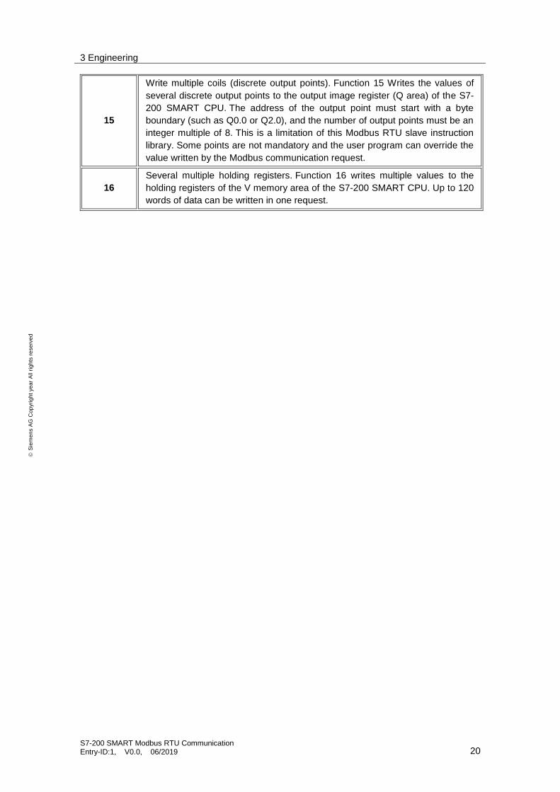
15
Write multiple coils (discrete output points). Function 15 Writes the values of
several discrete output points to the output image register (Q area) of the S7-
200 SMART CPU. The address of the output point must start with a byte
boundary (such as Q0.0 or Q2.0), and the number of output points must be an
integer multiple of 8. This is a limitation of this Modbus RTU slave instruction
library. Some points are not mandatory and the user program can override the
value written by the Modbus communication request.
16
Several multiple holding registers. Function 16 writes multiple values to the
holding registers of the V memory area of the S7-200 SMART CPU. Up to 120
words of data can be written in one request.

3 Engineering
S7-200 SMART Modbus RTU Communication Entry-ID:1, V0.0, 06/2019 21
S
iem
en
s A
G C
op
yri
gh
t yea
r A
ll ri
gh
ts r
ese
rve
d
3.3 Operation
Step 1: Initialize and monitor the Modbus Master by calling MBUS_CTRL on every scan. The
Modbus Master is set 9.6KBps and no parity. The Slave Device is allowed 1000 milliseconds (1
Second) to respond.

3 Engineering
S7-200 SMART Modbus RTU Communication Entry-ID:1, V0.0, 06/2019 22
S
iem
en
s A
G C
op
yri
gh
t yea
r A
ll ri
gh
ts r
ese
rve
d
Step 2: On the First Scan, reset the enable flags (M2.0 to M3.0) used for more than one
MBUS_MSG instruction.

3 Engineering
S7-200 SMART Modbus RTU Communication Entry-ID:1, V0.0, 06/2019 23
S
iem
en
s A
G C
op
yri
gh
t yea
r A
ll ri
gh
ts r
ese
rve
d
Step 3: Call the MBUS_MSG instruction when the first enable flag (M2.0) is ON. The First
parameter must be set for only the first scan that the instruction is enabled. This instruction
writes (RW = 1) 50 holding registers to slave 1. The write data is taken from VB1100-VB1198
(50 words) in the CPU and written to address 40001 - 40100 in the Modbus slave.
Step 4: Time calculation sending Data
The Begin interval time instruction reads the current value of the built-in 1 millisecond counter
and stores the value in OUT.
Step 5: The Calculate interval time instruction calculates the time difference between the
current time and the time provided at IN. The difference is stored in OUT.

3 Engineering
S7-200 SMART Modbus RTU Communication Entry-ID:1, V0.0, 06/2019 24
S
iem
en
s A
G C
op
yri
gh
t yea
r A
ll ri
gh
ts r
ese
rve
d
Step 6: When the first MBUS_MSG instruction is complete (Done goes from 0 to 1), clear the
enable for the first MBUS_MSG and set the enable for the second MBUS_MSG instruction. If
Error (MB1) is not zero, then set Q0.1 to show the error.
Step 7: Call the MBUS_MSG instruction when the enable flag (M2.1) is ON. The First
parameter must be set for only the first scan that the instruction is enabled. This instruction
reads (RW = 0) 50 holding registers to slave 1. The read data is taken in VB1200-VB1298 (50
words) in the CPU and written to address 40001 - 40100 in the Modbus slave.

3 Engineering
S7-200 SMART Modbus RTU Communication Entry-ID:1, V0.0, 06/2019 25
S
iem
en
s A
G C
op
yri
gh
t yea
r A
ll ri
gh
ts r
ese
rve
d
Step 8: Time calculation Reading Data
The Begin interval time instruction reads the current value of the built-in 1 millisecond counter
and stores the value in OUT.
Step 9: The Calculate interval time instruction calculates the time difference between the
current time and the time provided at IN. The difference is stored in OUT.
Step 10: When the first MBUS_MSG instruction is complete (Done goes from 0 to 1), clear the
enable for the first MBUS_MSG and set the enable for the second MBUS_MSG instruction. If
Error (MB1) is not zero, then set Q0.1 to show the error.
Step 11: Adding Of Both Send and Receiving Time of Data.

3 Engineering
S7-200 SMART Modbus RTU Communication Entry-ID:1, V0.0, 06/2019 26
S
iem
en
s A
G C
op
yri
gh
t yea
r A
ll ri
gh
ts r
ese
rve
d
Result: Communication Result: Data transfer from Master to Slave

3 Engineering
S7-200 SMART Modbus RTU Communication Entry-ID:1, V0.0, 06/2019 27
S
iem
en
s A
G C
op
yri
gh
t yea
r A
ll ri
gh
ts r
ese
rve
d
3.4 Error handling
The high numbered error codes (starting with 101) are errors that are returned by the
Modbus slave device. These errors indicate that the slave does not support the requested
function or that the requested address (either data type or range of addresses) is not supported
by the Modbus slave device.
The low numbered error codes (1 through 12) are errors that are detected by the
MBUS_MSG instruction. These error codes generally indicate a problem with the input
parameters of the MBUS_MSG instruction, or a problem receiving the response from the slave.
Parity and CRC errors indicate that there was a response but that the data was not received
correctly. This is usually caused by an electrical problem such as a bad connection or electrical
noise.
MBUS_CTRL Error Code
Description
0 No error
1 Invalid parity type
2 Invalid baud rate
3 Invalid timeout
4 Invalid mode
9 Invalid port number
10 Signal board port 1 missing or not configured
MBUS_MSG Error Code
Description
0 No error
1
Parity error in response: This is only possible if even or odd parity is used. The transmission was disturbed and possibly incorrect data was received. This error is usually caused by an electrical problem such as incorrect wiring or electrical noise affecting the communication.
2 Not used
3
Receive timeout: There was no response from the slave within the Timeout time. Some possible causes are bad electrical connections to the slave device, master and slave are set to a different baud rate / parity setting, and incorrect slave address.
4 Error in request parameter: One or more of the input parameters (Slave, RW, Address, or Count) is set to an illegal value. Check the documentation for allowed values for the input parameters.
5 Modbus master not enabled: Call MBUS_CTRL on every scan prior to calling MBUS_MSG.
6 Modbus is busy with another request: Only one MBUS_MSG instruction can be active at a time.
7 Error in response: The response received does not correspond to the request. This indicates some problem in the slave device or that the wrong slave device answered the request.
8 CRC error in response: The transmission was disturbed and possibly incorrect data was received. This error is usually caused by an electrical problem such as incorrect wiring or electrical noise affecting the communication.
11 Invalid port number

3 Engineering
S7-200 SMART Modbus RTU Communication Entry-ID:1, V0.0, 06/2019 28
S
iem
en
s A
G C
op
yri
gh
t yea
r A
ll ri
gh
ts r
ese
rve
d
MBUS_MSG Error Code
Description
12 Signal board port 1 missing or not configured
101 Slave does not support the requested function at this address: See the required Modbus slave function support table in the "Using the Modbus master Instructions" help topic.
102 Slave does not support the data address: The requested address range of Address plus Count is outside the allowed address range of the slave.
103 Slave does not support the data type: The Address type is not supported by the slave device.
104 Slave device failure
105 Slave accepted the message but the response is delayed: This is an error for MBUS_MSG and the user program should resend the request at a later time.
106 Slave is busy and rejected the message: You can try the same request again to get a response.
107 Slave rejected the message for an unknown reason.
108 Slave memory parity error: There is an error in the slave device.
Common mistakes / Error :
If multiple MBUS_MSG instructions are enabled at the same time, it will cause
error number 6.
If the slave delay parameter is set too long, the master station number 3 error
will be caused.
The slave station loses power or does not run, the network failure will cause the
main station number 3 error.
Allocate memory for library instructions in the V data area of the CPU (Library
Memory). The Modbus Master instruction library requires a 286-byte global V
memory area. Calling the STEP 7 - Micro/WIN SMART Instruction Library
requires the allocation of the library instruction data area (Library Memory). The
library instruction data area is the variable storage space used by the
subroutine and interrupt program of the corresponding library. If the library
instruction data area is not allocated during programming, many identical errors
are generated at compile time.
MBUS_SLAVE Error Code
Description
0 No error
1 Memory range error
2 Invalid baud rate or parity
3 Illegal slave address
4 Illegal value for Modbus parameter
5 Holding registers overlap Modbus Slave symbols
6 Receive parity error
7 Receive CRC error
8 Illegal function request/function not supported
9 Illegal memory address in request
10 Slave function not enabled
11 Invalid port number
12 Signal board port 1 missing or not configured

4 Additional information
S7-200 SMART Modbus RTU Communication Entry-ID:1, V0.0, 06/2019 29
S
iem
en
s A
G C
op
yri
gh
t yea
r A
ll ri
gh
ts r
ese
rve
d
4 Additional information
Additional notes on the Modbus RTU Master Protocol library Modbus address
Usually the Modbus addresses are five-to-six digit numbers that indicate the data type
as well as the address value. Modbus RTU master instructions map the address to the correct
functions to send to the slave device. (The address corresponds to the Addr input parameter of
the MBUS_MSG/MB_MSG2 instruction.) The Modbus address definitions are as follows:
00001 - 09999: Digital output (coil)
10001 - 19999: Digital input (contact)
30001 - 39999: Input data register (usually analog input)
(40001 to 49999) and (400001 to 465535) are holding registers
Features supported by the Modbus Master protocol library
In order to support reading and writing of the above Modbus address, the Modbus
Master protocol library requires the slave to support the following functions:
Table 1. Features that require slave support
Modbus address Read/write Functions to be supported by Modbus slaves
00001 - 09999 digital output
read Function 1
write Function 5: Write single output point Function 15: Write multiple output points
10001 - 19999 digital input
read Function 2
write -
30001 - 39999 input register
read Function 4
write -
40001 – 49999 holding registers 400001 - 465535
read Function 3
write Function 6: Write Single Register Unit Function 16: Write Multiple Register Unit
Mapping of Modbus addresses and S7-200 SMART memory area addresses
When the S7-200 SMART communicates with the Slave protocol library via Modbus
Master, the mapping relationship between the Modbus address and the storage area address in
the S7-200 SMART CPU is similar.
Modbus keep register address mapping example:
Modbus holding register address
40001 12 34
40002 56 78
40003 9A BC
S7-200 SMART Memory Word Addressing
VW200 12 34
VW202 56 78
VW204 9A BC
S7-200 SMART Memory Byte Addressing
VB200 12
VB201 34
VB202 56
VB203 78
VB204 9A
VB205 BC
Modbus digital address mapping example:

4 Additional information
S7-200 SMART Modbus RTU Communication Entry-ID:1, V0.0, 06/2019 30
S
iem
en
s A
G C
op
yri
gh
t yea
r A
ll ri
gh
ts r
ese
rve
d
The CPU reads and writes the bit data (addresses 0xxxx and 1xxxx) areas as packed
bytes; that is, each byte consists of 8 bits of data. The least significant bit of the first data byte is
the addressed bit number (the parameter Address). If you intend to write only a single bit then
you must set the bit in the least significant bit (Vx.0) of the byte pointed to by DataPtr. As shown
below:
Figure 6. Format for Packed Bytes (Discrete Input Addresses)

5 Appendix
S7-200 SMART Modbus RTU Communication Entry-ID:1, V0.0, 06/2019 31
S
iem
en
s A
G C
op
yri
gh
t yea
r A
ll ri
gh
ts r
ese
rve
d
5 Appendix
5.1 Service and support
Industry Online Support
Do you have any questions or need assistance?
Siemens Industry Online Support offers round the clock access to our entire service and support know-how and portfolio.
The Industry Online Support is the central address for information about our products, solutions and services.
Product information, manuals, downloads, FAQs, application examples and videos – all information is accessible with just a few mouse clicks: support.industry.siemens.com
Technical Support
The Technical Support of Siemens Industry provides you fast and competent support regarding all technical queries with numerous tailor-made offers – ranging from basic support to individual support contracts. Please send queries to Technical Support via Web form: www.siemens.com/industry/supportrequest
SITRAIN – Training for Industry
We support you with our globally available training courses for industry with practical experience, innovative learning methods and a concept that’s tailored to the customer’s specific needs.
For more information on our offered trainings and courses, as well as their locations and dates, refer to our web page: www.siemens.com/sitrain
Service offer
Our range of services includes the following:
Plant data services
Spare parts services
Repair services
On-site and maintenance services
Retrofitting and modernization services
Service programs and contracts
You can find detailed information on our range of services in the service catalog web page: support.industry.siemens.com/cs/sc

5 Appendix
S7-200 SMART Modbus RTU Communication Entry-ID:1, V0.0, 06/2019 32
S
iem
en
s A
G C
op
yri
gh
t yea
r A
ll ri
gh
ts r
ese
rve
d
Industry Online Support app
You will receive optimum support wherever you are with the "Siemens Industry Online Support" app. The app is available for Apple iOS, Android and Windows Phone: support.industry.siemens.com/cs/ww/en/sc/2067
5.2 Support
Siemens Ltd
DI FA AS
Thane Belapur Road Thane 400601, India
Application Center
SUP FA
Email: [email protected]
5.3 Links and literature
Table 5-1
No. Topic
\1\ Siemens Industry Online Support
https://support.industry.siemens.com
\2\ Link to this entry page of this application example
https://support.industry.siemens.com/cs/ww/en/view/Entry ID
\3\
5.4 Change documentation
Table 5-2
Version Date Modifications
V1.0 MM/YYYY First version