master drainage plan report on mustang bayou, chocolate …
TRANSCRIPT
MASTER DRAINAGE PLAN REPORT
ON
MUSTANG BAYOU, CHOCOLATE BAYOU, DITCH C-1, DITCH M-1,
NEW BAYOU, HALLS BAYOU, CHIGGER CREEK, DITCH D-4 AND DICKINSON BAYOU
WATERSHEDS
PREPARED FOR
BRAZORIA COUNTY CONSERVATION & RECLAMATION DISTRICT NO. 3
THE TEXAS WATER DEVELOPMENT BOARD
PREPARED BY
SNOWDEN ENGINEERING, INC.
JUNE, 1989
SNOWDEN ENGINEERING, INC. Houston. Pearland, Texas

TABLE OF CONTENTS
I. Introduction
A. General
B. Authorization and Acknowledgement
II. Background Consideration
A. General Location
B. Land Use
C. Topographic Features
D. Soil Characteristics
E. Flooding Problems
F. Prior Studies
III. Existing Flooding Conditions
A. General
B. Hydrologic Analysis
C. Hydraulic Analysis
IV. Proposed Improvements
A. General
B. Hydrologic Analysis
C. Hydraulic Analysis
D. Recommended Plans
V. Conclusion
SNOWDEN ENGINEERING, INC. HOUSlOn • Pearland, Texas

I.
II.
III.
IV.
V.
EXHIBITS
Vicinity Map
Drainage Boundaries for Mustang Bayou, Ditch M-I, New Bayou, Chocolate Bayou, Ditch C-I, Halls Bayou, Chigger Creek, Ditch D-4, and Dickinson Bayou.
Mustang Bayou Watershed & Subwatershed Boundaries
Chocolate Bayou Watershed & Subwatershed Boundaries
Halls Bayou, Chigger Creek, Ditch D-4 and Dickinson Bayou Watershed and Subwatershed Boundaries
VI. Existing IOO-year and 25-year Flood Limits on Mustang Bayou, Ditch M-I and New Bayou
VII.
VIII.
IX.
X.
XI.
XII.
XIII.
XIV.
xv.
XVI.
XVII.
Existing IOO-year and 25-year Flood Limits Chocolate Bayou and Ditch C-I
Existing IOO-year and 25-year Flood Limits on Halls Bayou, Chigger Creek, Ditch D-4 and Dickinson Bayou
Existing IOO-year and 25-year Water Surface Profiles on Mustang Bayou
Existing IOO-year and 25-year Water Surface Profiles on Ditch M-I
Existing IOO-year and 25-year Water Surface Profiles on New Bayou
Existing IOO-year and 25-year Water Surface Profiles on Chocolate Bayou
Existing IOO-year and 25-year Water Surface Profiles on Ditch C-I
Existing IOO-year and 25-year Water Surface Profiles on Halls Bayou
Existing IOO-year and 25-year Water Surface Profiles on Chigger Creek
Existing IOO-year and 25-year Water Surface Profiles on Ditch D-4
Existing IOO-year and 25-year Water Surface Profiles on Dickinson Bayou
I
SNOWDEN ENGINEERING, INC. Houston. Pearland. Texas

XVIII. Proposed Improvements on Mustang Bayou, Ditch M-I and New Bayou
XIX. Proposed Improvements on Chocolate Bayou, Ditch C-I
XX. Proposed Improvements on Halls Bayou, Chigger Creek, Ditch D-4 and Dickinson Bayou
XXI. Proposed IOO-year and 25-year Water Surface Profiles on Mustang Bayou
XXII. Proposed IOO-year and 25-year Water Surface Profiles on Ditch M-I
XXIII. Proposed IOO-year and 25-year Water Surface Profiles on New Bayou
XXIV. Proposed IOO-year and 25-year Water Surface Profiles on Chocolate Bayou
XXV. Proposed IOO-year and 25-year Water Surface Profiles on Ditch C-I
XXVI. Proposed IOO-year and 25-year Water Surface Profiles on Halls Bayou
XXVII. Proposed IOO-year and 25-year Water Surface Profiles on Chigger Creek
XXVIII. Proposed IOO-year and 25-year Water Surface Profiles on Ditch D-4
XXIX. Proposed IOO-year and 25-year Water Surface Profiles on Dickinson Bayou
2
SNOWDEN ENGINEERING, INC. Houston • Pearland. Texas

I.
II.
III.
IV.
V.
VI.
VII.
VIII.
IX.
TABLES
Input Parameters for Mustang Bayou
Input Parameters for Ditch M-I
Input Parameters for New Bayou
Input Parameters for Chocolate Bayou
Input Parameters for Ditch C-I
Input Parameters for Halls Bayou, Chigger Creek, Ditch D-4 and Dickinson Bayou
HEC-I Results for Mustang Bayou, Ditch M-I and New Bayou
HEC-I Results for Chocolate Bayou and Ditch C-I
HEC-I Results for Halls Bayou, Chigger Creek, Ditch D-4 and Dickinson Bayou
3
SNOWDEN ENGINEERING. INC. Houston • Pearland. Texas

I.
II.
III.
IV.
V.
VI.
VII.
VIII.
IX.
APPENDIX
HEC-I Printout on Mustang Bayou Watershed for IOO-year and 25-year Frequency Storms under existing conditions
HEC-I Printout on Chocolate Bayou Watershed for IOO-year and 25-year Frequency Storms under existing conditions
HEC-I Printout on Halls Bayou Watershed for IOO-year and 25-year Frequency Storms under existing conditions
HEC-I Printout on Chigger Creek Watershed for IOO-year and 25-year Frequency Storms under existing conditions
HEC-I Printout on Ditch D-4 Watershed for IOO-year and 25-year Frequency Storms under existing conditions
HEC-I Printout on Dickinson Bayou Watershed for IOO-year and 25-year Frequency Storms under existing conditions
HEC-2 Printout on Mustang Bayou for IOO-year and 25-year Frequency Storms under existing conditions
HEC-2 Printout on Ditch M-I for IOO-year and 25-year Frequency Storms under existing conditions
HEC-2 Printout pn New Bayou for IOO-year and 25-year Frequency Storms under existing conditions
X. HEC-2 Printout on Chocolate Bayou for IOO-year and 25-year Frequency Storms under existing conditions
XI. HEC-2 Printout on Ditch C-I for IOO-year and 25-year Frequency Storms under existing conditions
XII.
XIII.
XIV.
xv.
XVI.
XVII.
HEC-2 Printout on Halls Bayou for IOO-year and 25-year Frequency Storms under existing conditions
HEC-2 Printout on Chigger Creek for IOO-year and 25-year Frequency Storms under existing conditions
HEC-2 Printout on Ditch D-4 for IOO-year and 25-year Frequency Storms under existing conditions
HEC-2 Printout on Dickinson Bayou for IOO-year and 25-year Frequency Storms under existing conditions
HEC-I Printout on Mustang Bayou Watershed for IOO-year and 25-year under proposed conditions
HEC-I Printout on Chocolate Bayou Watershed for IOO-year and 25-year under proposed conditions
4
SNOWDEN ENGINEERING, INC. Houston. Pearland, Texas

XVIII. HEC-l Printout on Halls bayou Watershed for lOO-year and 25-year under proposed conditions
XIX. HEC-l Printout on Chigger Creek Watershed for lOO-year and 25-year under proposed conditions
XX. HEC-l Printout on Ditch 0-4 Watershed for lOO-year and 25-year under proposed conditions
XXI. HEC-l Printout on Dickinson Bayou Watershed for lOO-year and 25-year under proposed conditions
XXII. HEC-l Printout on Mustang Bayou for lOO-year and 25-year under proposed conditions
XXIII. HEC-2 Printout on Ditch M-l for lOO-year and 25-year under proposed conditions
XXIV. HEC-2 Printout on New Bayou for lOO-year and 25-year under proposed conditions
XXV. HEC-2 Printout on Chocolate Bayou for lOO-year and 25-year under proposed conditions
XXVI. HEC-2 Printout on Ditch C-l for lOO-year and 25-year under proposed conditions
XXVII. HEC-2 Printout on Halls Bayou for lOO-year and 25-year under proposed conditions
XXVIII. HEC-2 Printout on Chigger Creek for lOO-year and 25-year under proposed conditions
XXIX.
XXX.
HEC-2 Printout on Ditch 0-4 for lOO-year and 25-year under proposed conditions
HEC-2 Printout on Dickinson Bayou for lOO-year and 25-year under proposed conditions
5
SNOWDEN ENGINEERING, INC. Houston. Pearland. Texas

I. Introduction
A. General
The Brazoria County Conservation and Reclamation
District No. 3 (the District) and the Texas Water
Development Board (the Board) contracted with Snowden
Engineering, Inc. in June 1987 to perform a Master
Drainage Plan for the District. The study includes:
1) Preparation of the existing hydrologic and
hydraulic models for Mustang Bayou, Ditch M-l, New
Bayou, Chocolate Bayou, Ditch C-l, Halls Bayou,
Chigger Creek, Dickinson Bayou, and Ditch D-4; 2)
Development of flood damage abatement measures for
each of the streams studied and evaluation of the
benefi t-to-cost ratio for all the measures; 3 )
Recommendation of the best features of the most
feasible alternatives for each watershed, and 4)
Preparation of a drainage manual to assist developers
in the design of drainage improvements.
The Phase One Study has been completed which includes
Mustang Bayou, Ditch M-I, New Bayou, Chocolate Bayou,
and Ditch C-I. A preliminary report on the Phase One
Study was submitted to the District and the Board in
December 1988 • The report describes the flooding
6
SNOWDEN ENGINEERING, INC. Houston. Pearland. Texas

problems for each of these streams and analyzes all
flood damage abatement measures including the struc-
tural, non-structural and no action alternatives.
The Phase Two Study has also been completed which
included Halls Bayou, Chigger Creek, Ditch D-4 and
Dickinson Bayou. A preliminary report on the Phase
Two Study was submitted to the District and the Board
in May 1989. The report describes the flooding
problems for each of these streams and analyzes all
flood damage abatement measures including the
structural, non-structural, and no action alterna-
tives. The purpose of this report is to evaluate
results of Phases One and Two and combine the best
features of the most feasible alternatives for each
watershed analyzed in the two-phases.
B. Authorization and Acknowledgement
This project was authorized by both the District and
the Board. Snowden Engineering, Inc. wishes to
express its sincere appreciation for the cooperation
and assistance received from the District, the Board
and the local officials during the study period.
7
SNOWDEN ENGINEERING. INC. Houston. Pearland. Texas
II. Background Consideration
A. General Location
The District encompasses approximately 180 square
miles of land in northeast Brazoria County. The
District is bounded by Chocolate Bayou on the west,
Chocolate Bay on the south, the Brazoria/Galveston
County line on the east and essentially the American
Canal on the north as shown on Exhibit I.
1. Mustang Bayou: Mustang Bayou runs through the
center of the District. The headwater of Mustang
Bayou is inside the city limits of Missouri City
which is located in Fort Bend County. The bayou
flows in a southeast direction through the county
line, the Cities of Manvel, Alvin and Hillcrest
Village and outfalls in Chocolate Bay in the
southeast corner of the District. An area of
approximately 62 square miles south of FM 2004
(including Ditch M-l and New Bayou) drains from
the headwater to the south of the confluence with
New Bayou. Exhibit II shows the drainage
boundaries of Mustang Bayou, Ditch M-l, New Bayou,
Ditch C-l and Chocolate Bayou.
8
SNOWDEN ENGINEERING, INC. Houston. Pearland. Texas

2. Ditch M-l: A man-made tributary of Mustang Bayou,
Ditch M-l originates in the western part of Alvin
and outfalls in Mustang Bayou approximately 6
miles southeast of Alvin. Ditch M-l provides a
certain capacity for drainage of the south and
west portions of the City of Alvin. A total of
7.8 square miles of drainage area is covered by
Ditch M-l.
3. New Bayou: A relief channel to Ditch C-l (main
tributary of Chocolate Bayou), New Bayou origi-
nates from Ditch C-l near County Road 169 and
outfalls into Mustang Bayou near FM 2004 with a
drainage area of 8.5 square miles.
4. Chocolate Bayou: The headwaters are located north
of Texas State Highway (SH) 6 approximately 1.4
miles west of the City of Manvel. The headwaters
of the West Fork Chocolate Bayou begin near Arcola
in southeast Fort Bend County and outfall into
Chocolate Bayou approximately 2.5 miles south of
FM 1128. The total drainage area of Chocolate
Bayou at FM 2004 is 170 square miles including
Ditch C-l.
9
SNOWDEN ENGINEERING, INC. Hou$[un - Pearland, Texas

5. Ditch C-I: A man-made tributary of Chocolate
Bayou, Ditch C-I originates at the northwest
corner of the District near Manvel and flows
southeasterly along the Brazos River Authority
(BRA) Canal, formerly known as the Briscoe Canal,
for approximately 8.2 miles then turns south and
outfalls into Chocolate Bayou near Liverpool. The
total drainage area of Ditch C-I is 20 square
miles.
6. Halls Bayou: Halls Bayou runs along the east side
of the District near the Galveston/Brazoria County
line. The headwater is located north of the
Missouri Pacific Railroad and southeast of
Hillcrest Village. The bayou flows in a south-
easterly direction through County Road (CR) 165,
BRA Canal, Halls Bayou Road, FM 2004 to Halls Lake
and Chocolate Bay. A total drainage area of
approximately 30 square miles is included in the
Halls Bayou watershed to FM 2004. Exhibit II
shows the drainage boundary for Halls Bayou,
Chigger Creek, Dickinson Bayou and Ditch D-4.
7. Chigger Creek: Chigger Creek runs along the
northeast corner of the District. The headwater
is located at the east side of Mustang Bayou and
10
SNOWDEN ENGINEERING, INC. Houston. Pearland. Texas
the City of Manvel. The creek f lows in an
easterly direction through the District to
Brazoria County Drainage District No. 4 and
outfalls into Clear Creek. A total drainage area
of approximately 2.5 square miles is included in
the Chigger Creek watershed within the District's
boundary as shown on Exhibit II.
8. Dickinson Bayou: In this study, Dickinson Bayou
only covers about one mile in length and is at
the most upstream portion of the Bayou. The head-
water of Dickinson Bayou is located on State
Highway (SH) 35 south of Chigger Creek. The bayou
flows in a southeastern direction through the BRA
Canal and to the Galveston County line. A total
drainage area of approximately 0.5 square miles
is included in the Dickinson Bayou watershed to
the Galveston/Brazoria County line as shown on
Exhibit II.
9. Ditch D-4: Ditch D-4 is a man-made tributary of
Dickinson Bayou. The ditch originates from
Chigger Creek at CR 99 and flows in a south-
easterly direction through CR 152, CR 144, the
A.T.S.F. Railroad, SH 409, SH 35, and SH 528 to
the County line as shown on Exhibit II. A total
11
SNOWDEN ENGINEERING, INC. Houston. Pearland, Texas
drainage area of approximately 4.8 square miles
is included in the Ditch D-4 watershed to the
Galveston/Brazoria County line.
B. Land Use
The District is predominantly rural farm and ranch
land, although various petro-chemical industries have
been established at the lower reaches of the major
streams. The Cities of Manvel and Alvin are within
the District boundary~ Liverpool, Arcola and portions
of Missouri City are within the boundary of the study
area. The main components of SH 288, the South
Freeway, which crosses the study area have been
completed and the construction of grade separation is
underway. Significant development is expected to
occur along the South Freeway corridor.
C. Topographic Features
Topography of the study area slopes generally from
the northwest toward the southeast with a very mild
slope of 0.04 percent. The elevation rises from the
Mean Sea Level (MSL) at Chocolate Bay to approximately
75 feet MSL in the uppermost part of the study area.
Most of the drainage area flows to the southeast
12
SNOWDEN ENGINEERING, INC. Houston. Pearland, Texas

through Chocolate Bayou, Mustang Bayou and New Bayou.
Natural drainage patterns have been altered throughout
the District by the construction of supplemental
drainage channels and irrigation canals. The levees
enclosing the BRA Canal, which was constructed in the
1940's, have effectively blocked overland sheet flow
in several locations of the study area.
D. Soil Characteristics
Within the study area, a great portion of the surface
soil is classified as Lake Charles or Bernard-Edna
except a small portion south of FM 2004 which belongs
to Edna-Aris, Francitas-Narta and Harris-Veston. All
of the soils are compiled of clay and loam and are
poorly drained and have very low permeability. Rice
and soybeans are the main cultivated crops.
E. Flooding Problems
During the past years, the drainage system within the
study area has been inadequate for numerous rainfall
events. Widespread flooding has caused physical
damage to dwellings, crops, bridges, and roads
estimated to be in the millions of dollars. Residen-
tial and commercial damage from tropical storm
13
SNOWDEN ENGINEERING. INC. Houston. Pearland. Texas

nClaudette" (July 1979) which brought 26 inches of
rain in 24 hours in the Mustang Bayou Watershed was
estimated to be at $20 million. Other major flooding
events occurred in July 1939, October 1949, March
1957, September 1973, September 1979, and August 1983.
For many years the area was primarily for agricultural
use only; but as urbanization occurred in the water-
shed, the potential for more serious flood damage in
the study area increased. Extensive improvements will
be required to eliminate the existing flooding pro-
blems and provide adequate drainage for future
development in the study area.
F. Prior Studies
Various studies conducted previously for portions of
these watersheds are as follows:
1. "Tropical Storm Claudette" by U.S. Army Corps
of Engineers, Galveston, Texas, September 1980.
2. "Flood Damage Prevention, Feasibility Report
for Dickinson Bayou Watershed, Texas" by U.S.
Army, Corps of Engineers, Galveston, Texas.
14
SNOWDEN ENGINEERING, INC. Houston. Pearland. Texas

3. "Flood Control Planning Study on Chigger and
Cowarts Creek for the Brazoria County Drainage
District No. 4 and the Texas Water Development
Board" by COENCO, Inc., December 1986.
4. "Drainage Master Plan for Brazoria County C&R
3" by Turner, Collie, & Braden, Inc. August
1974.
5. "Report on Investigation of Outfall Channel
for Mustang Bayou" by Turner, Collie, & Braden,
July 1975.
6. "Engineering Report for Brazoria County C&R 3"
by Baker and Lawson, April 1980.
7. "Floodplain Information, Chocolate Bayou,
Brazoria County Texas" by U.S. Army, Corps of
Engineers, Galveston, Texas, June 1971.
8. "Flood Insurance Study of Brazoria County,
Texas" by U. S. Federal Emergency Management
Agency, August 1986.
15
SNOWDEN ENGINEERING, INC. Housron • Pearland, T eX3S

9. "High Flood Hazard Area Studies, Alvin, Texas"
by U.S. Army, Corps of Engineers, Galveston,
Texas, September 1986.
10. "Physical and Economic Feasibili ty of Nonstruc-
tural Flood Plain Management Measures" by U.S.
Army, Corps of Engineers, March 1978.
16
SNOWDEN ENGINEERING, INC. Housfon • Pearland, Texas

III. Existing Condition
A. General
All streams in the study area have inadequate capacity
for a 25-year or lOO-year frequency flood. The most
serious flooding problem in the study area occurred
in the vicinity of the most populated area, the City
of Alvin. This is due to the limited right-of-way of
Mustang Bayou and the heavy growth of vegetation
inside the banks. Inside the Alvin city limits, high
density residential and commercial buildings also form
a blockage of the flow's path. The hydrologic and
hydraulic analyses for the existing conditions of each
stream studied are explained as shown in the following
sections.
B. Hydrologic Analysis
In order to define the current flooding condition for
each stream, HEC-l models were developed for each
watershed. These models were then adjusted for the
reach routing based on the results of HEC-2 model
multiple runs. The 25-year and lOO-year flows thus
calculated from the HEC-l model will be used in the
HEC-2 model at each control point for the calculation
17
SNOWDEN ENGINEERING, INC. Houston. Pearland. Texas

of the 25-year and lOO-year water surface profiles
along each stream.
The input parameters for HEC-l model includes drainage
area, length of water course, slope of water course,
slope of watershed, Manning's coefficient, and
percentage of impervious area for each subwatershed.
Additional information such as rainfall distribution
for a 24 hour period, initial rainfall loss and
constant loss through the period will be input as a
constant parameter through each subwatershed. Two
major items that will reflect the shape of the
hydrographs were the time of concentration (Tc) and
the storage coefficient (R). These two variables are
calculated based on the equations adopted by Fort Bend
county Drainage District. The flows that generated
from the HEC-l model were used to input the HEC-2
model for hydraulic calculations. Exhibits III
through V show the locations of each watershed and
control points for the HEC-l model. Tables I through
VI show the input parameters at each control point
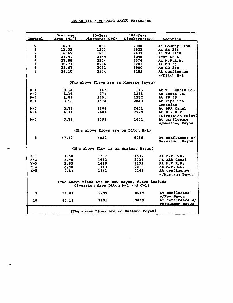
from each subwatershed. Tables VII through IX show
the 25-year and lOO-year discharges at each control
point for each subwatershed. Appendix I through VI
show the printouts for HEC-l models for each water-
shed.
18
SNOWDEN ENGINEERING, INC. Houston. Pearland. Texas

C. Hydraulic Analysis
In order to calculate the 25-year and lOO-year water
surface profiles and the flooding limits along each
stream, the HEC-2 model was used to perform the
computations. The primary input data required for
the HEC-2 model is the cross section data of the
stream and the over banks. For streams such as Mustang
Bayou, Chocolate Bayou, and Halls Bayou, the latest
computer model from the Federal Emergency Management
Agency (FEMA) was updated to reflect the existing
condition. All other streams were based upon the
surveyed cross sections by Snowden Engineering, Inc.
The overbank extensions were based on U.S.G.S.
quadrant map with adjustments to 1979 elevations.
The results of the HEC-2 model were used to develop
flood plain maps and water surface profiles for each
stream. Exhibits VI through VIII show the flooding
limits for the existing 25-year and lOO-year frequency
flood for each stream. Exhibits IX through XVII show
the corresponding water surface profile along the
streams. Appendix VII through XV show the HEC-2
printouts for each studied stream.
19
SNOWDEN ENGINEERING, INC. Houston. Pearland. Texas
IV. Proposed Improvements
A. General
This Master Drainage Plan presents the drainage
improvements for each studied watershed under the
existing condition as well as the fully developed
condition with onsite detention to control increased
runoff from future development. Various proposed
alternatives for drainage improvements have been
studied and presented in the summary of Phase I and
Phase II. To combine the best features of the most
feasible alternatives for each watershed in the two
phases of studies is the key to the recommendation of
the proposed improvements. Based on the summary
report for Phase I and II, almost all improvement
alternatives for the major streams and tributaries
have a cost-to-benefi t ratio less than one except
Chigger Creek and Dickinson Bayou. Hence, it becomes
impractical to determine the best alternatives based
only on the economical factors. The recommendations
of the proposed improvements for each stream should
then be based on the feasibility of the solution.
20
SNOWDEN ENGINEERING, INC. Houston. Pearland, Texas

B. Hydrologic Analysis
The study is based on the existing land development
conditions. All future development will require on-
site detention to retard the developed flow to its
undeveloped condition. The major factor that will
change the f low along the stream is the proposed
channel improvement on the stream. The HEC-l input
is thus adjusted by a new set of reach routing
information obtained from the revised HEC-2 model (or
proposed improvement model) multiple runs. The new
flows resulting from these HEC-l runs will be used to
input to the HEC-2 model for the hydraulic calcula-
tions.
C. Hydraulic Analysis
The revised HEC-2 model for each stream reflects the
proposed improvements and the new 25- year and 100-
year discharges from the HEC-l run. The results of
these HEC-2 runs will be used to estimate the
construction cost and to evaluate the feasibility of
the alternatives.
21
SNOWDEN ENGINEERING, INC. Houstun • Pearland, Texas

D. Recommended Plans
Due to the wide spread flooding problem in the study
area and the large drainage area covering a minimum
of 270 square miles, a District-wide flood forecasting
or flood warning system is recommended for immediate
action. This is a warning system to determine the
imminent flooding and to warn the public and organiza-
tions of assistance in the temporary evacuation of
persons and personal property. The most elaborate
warning system utilizes remote sensors to transmit
real-time rainfall and water level data to a micro-
computer. The microcomputer is used to coordinate the
data acquisition, management, analysis and communi-
cation tasks. An automated stream flow forecast
system can also be operated by the microcomputer.
Wi th all this information, the District can accurately
track storm conditions and forecast potential problem
areas for the emergency evacuation plan.
It is recommended that 32 stations be installed in
the study area as shown in Exhibits XVIII through xx.
Based on an estimated cost of $5,000.00 for each sta-
tion, the total will be $160,000.00 for the stations
(or sensors). A software package and an IBM-AT PC
microcomputer will cost approximately $20,000.00. A
22
SNOWDEN ENGINEERING, INC. Housron • Pearland, Texas

central station and personnel for operation, main-
tenance and inspection will be required on a permanent
basis.
The following recommendations for each watershed are
based on the feasibility of the improvements and the
phasing plan of each stream.
1. Mustang Bayou:
Four major factors that contribute to the flooding
problem and limit the degree of channel improve-
ments are:
a. Upstream contributing area from Fort Bend
County.
b. Limited rights-of-way in the City of Alvin.
c. Limited rights-of-way at the reservoir.
d. Tidal flooding.
The recommended plan on Mustang Bayou is based on
the existing condition upstream from the Fort Bend
County/Brazoria County Line and the existing top
23
SNOWDEN ENGINEERING, INC. Housfon • Pearland. Texas

of bank width on Mustang Bayou within the Alvin
city limits. A 40 foot bottom width earthen
channel with 3:1 side slopes is recommended from
the Ft. Bend/Brazoria County Line (Sec. BA on the
existing flood plain map) to an irrigation canal
(Sec AT). A 60 foot bottom width earthen channel
is recommended from the irrigation canal to a
proposed regional detention pond (Sec A). A
proposed 150 acre regional detention site is
recommended at this natural bend area. Downstream
from the proposed pond, the 60 foot bottom earthen
channel will be extended to the city limits of
Alvin (Sec 0). From the city limits to County
Route (CR) 160 (Sec W), a concrete lined section
with a 20 foot bottom width having 2:1 side slopes
is recommended to match the existing top of bank
due to the limited expansion on each side of the
bank. Downstream of CR 160, a 100 foot bottom
width earthen channel is recommended to the
southern limit of the Farms of Texas reservoirs
(Sec G). A 200 foot bottom width earthen channel
is recommended from this section to the confluence
with New Bayou. Downstream from the confluence
(Sec C), a 300 foot bottom width earthen ditch is
recommended to just upstream of Persimmon Bayou
(Sec Al. This recommended plan will confine the
24
SNOWDEN ENGINEERING, INC. Houston. Pearland, Texas

100-year flood in the bank from the Fort Bend/Bra-
zoria County line to FM 2004 except for tidal
flooding which will still extend upstream of the
existing reservoir. Exhibit XVIII shows the
proposed improvement plan for this stream and
Exhibit XXI shows the 100-year water surface
profile along this stream. The estimated
excavation quantity is 15.2 million cubic yards
and the concrete lined channel is 5.3 miles. The
total estimated construction cost will be $51.6
million including the replacement of bridge
structures, which is estimated to be 47 units.
The required right-of-way of 200 feet near the
uppermost part of Mustang Bayou near the county
line to 440 feet downstream near FM 2004 will be
acquired by the District for construction
purposes. Appendix XVI shows the HEC-l printouts
for the Mustang Bayou Watershed at the proposed
condition. Appendix XXII shows the HEC-2
printouts on Mustang Bayou for the proposed
condition.
25
SNOWDEN ENGINEERING, INC. Houston. Peatland, Texas

2. Ditch M-I
The major factors that contribute to the flooding
problem and limit the degree of channel improve-
ments in this watershed are:
a. Limited right-of-way of the existing two foot
bottom width ditch inside the City of Alvin.
b. Overloaded storm sewer systems and the two
foot bottom width concrete lined ditch.
c. Limited capacity of the existing 7-72" CMP
under the BRA Canal crossing.
The recommended plan on Ditch M-I is based on the
improved drainage system inside the City of Alvin
to limit the drainage area to the capacity of the
existing concrete lined channel. By doing this,
no improvements will be required upstream from the
existing concrete lining ditch. Downstream from
this ditch to State Highway (SH) 35, a 20 foot
bottom width concrete lined channel with 2:1 side
slopes is recommended. Downstream from SH 35 to
the confluence with Mustang Bayou, a 60 foot
bottom width earthen channel is recommended
26
SNOWDEN ENGINEERING, INC. Houston. Pearland, Texa.

together with additional 3-72" CMP underneath the
BRA Canal crossing.
This recommended plan will confine the 100-year
flood within the banks all along the channel.
The estimated excavation quantity is 1.9 million
cubic yards and the concrete lined channel is 1.2
miles. The total construction cost estimate is
$9.0 million including the replacement of bridge
structures, which is estimated to be 13 units.
The required right-of-way of 120 feet to 210 feet
will be acquired by the District for construction
purposes. Exhibit XVIII shows the proposed
improvement plan and Exhibit XXII shows the
proposed 100-year water surface profile along the
channel. Appendix XXIII shows the HEC-2 printouts
on Ditch M-l for the proposed condition.
3. New Bayou
New Bayou is one of very few streams that has a
fairly large capacity compared to the other
streams studied. The recommended plan on New
Bayou is based on zero diversion from either Ditch
M-l or Ditch C-l. The recommended plan calls for
a 20 foot bottom width earthen channel from CR 169
27
SNOWDEN ENGINEERING, INC. Housron • Pearland. Texas

(Sec L) to BRA Canal crossing (Sec H), a 60 foot
bottom width earthen channel downstream to the
Missouri Pacific Railroad crossing (Sec C) and a
100 foot bottom width earthen channel to the
conf luence with Mustang Bayou (Sec A). This
recommended plan will confine the 100-year flood
in the bank except the downstream area subjected
to tidal flooding. The estimated excavation
quantity is 0.8 million cubic yards and the
estimate construction cost is $1.7 million
including a bridge replacement at the dirty road
(Sec I). Required right-of-way of 150 feet to 240
feet will be acquired by the District for
construction purposes. Exhibit XVIII shows the
proposed improvement plan and Exhibit XXIII shows
the proposed 100-year water surface profile along
the stream. Appendix XXIV shows the HEC-2
printouts on New Bayou for the proposed condition.
28
SNOWDEN ENGINEERING, INC. Houston. Pearland, Texas

" -. 4. Chocolate Bayou
The major factors that contribute to the flooding
problem and limit the degree of channel improve-
ments are:
a. Upstream contributing area from Fort Bend
County.
b. The continuous meandering of the bayou.
c. Tidal flooding.
The recommended plan for Chocolate Bayou contains
both regional detention ponds and channel improve-
ment applications. These regional detention ponds
are proposed on West Fork Chocolate Bayou, Unnamed
Tributary, and Hayes Creek at the confluence with
Chocolate Bayou. The detention area of the 3
ponds is 250 acres, 150 acres and 200 acres,
respectively. The channel improvements begin
downstream from the BRA Canal to Rifle Range Road
with a 50 foot bottom width earthen channel, a 100
foot bottom width from Rifle Range Road downstream
to Hayes Road and a 200 foot bottom width earthen
channel from this point to SH 35 and a 300 foot
29
SNOWDEN ENGINEERING, INC. Housron • Pearland. Texas
bottom width earthen channel from SH 35 to FM
2004.
This recommended plan will contain lOO-year flood
in the bank all along the channel except for tidal
flooding which will still extend upstream of SH
35. Exhibit XIX shows the proposed improvement
plan for Chocolate Bayou and Exhibit XXIV shows
the 100-year water surface profile along the
bayou. The estimated excavation quantity is 32
million cubic yards including the regional
detention ponds. The total construction cost
estimate is $66.7 million including the replace-
ment of bridge structures, which is estimated to
be 18 bridge units. The required right-of-way
from 160 feet to 500 feet will be acquired by the
District for construction purposes. Appendix XVII
shows the HEC-2 printouts for Chocolate Bayou
Watershed at the proposed condition. Appendix XXV
shows the HEC-2 printouts for Chocolate Bayou at
the proposed condition.
5. Ditch C-l
The recommended plan for Ditch C-l is a 20 foot
bottom width earthen channel from Tankersley Road
30
SNOWDEN ENGINEERING, INC. Houstun • Pearland, Texas

to Old Rifle Road and a 40 foot bottom width
earthen channel for Old Rifle Road to the
confluence with Chocolate Bayou.
This recommended plan will confine the 100-year
flood in the bank all along the ditch except the
downstream area which is subject to tidal
flooding. Exhibit XIX shows the proposed im-
provement plan for Ditch C-l and Exhibit XXV shows
the 100-year water surface profile along the
ditch. The estimated excavation quantity is 3.2
million cubic yards. The total construction cost
estimate is $8.8 million including the replacement
of bridge structures, which is estimated to be 16
units. The required right-of-way from 140 feet
to 240 feet will be acquired by the District for
construction purposes. Appendix XXVI shows the
HEC-2 printouts for Ditch C-l at the proposed
condition.
6. Halls Bayou
The recommended plan on Halls Bayou is a 20 foot
bottom width earthen channel from County Road (CR)
159 to CR 165 and 50 foot bottom width from CR 165
to the pipeline crossings approximately 1 mile
31
SNOWDEN ENGINEERING, INC. Housron • Pearland, T eX3S

upstream from Halls Bayou Road. Downstream from
the pipeline crossings, a 100 foot bottom width
earthen channel is recommended for approximately
3 miles toward the south with no improvement on
channel for approximately 1.5 miles until it hits
FM 2004. South of FM 2004, a 200 foot bottom
width earthen channel is recommended for a
distance of approximately 1 mile.
This recommended plan will confine the 100-year
flood in the bank except the area downstream from
Halls Bayou Road which is still subject to tidal
flooding. Exhibit xx shows the proposed improve-
ment plan and Exhibit XXVI shows the 100-year
water surface profile along the bayou. The
estimated excavated quantity is 2.3 million cubic
yards. The total construction cost estimate is
$5.7 million including the replacement of bridge
structures, which is estimated to be 4 units. The
required right-of-way from 150 feet to 350 feet
will be acquired by the District for construction
purposes. Appendix XVIII shows the HEC-I
printouts for Halls Bayou Watershed at the
proposed condition. Appendix XVII shows the HEC-
2 printouts for Hall Bayou at the proposed condi-
tion.
32
SNOWDEN ENGINEERING, INC. Housron • Pearland, Texas
7. Chigger Creek
Because the existing creek drains into Brazoria
County Drainage District No.4 and Clear Creek in
Galveston County, a detention pond at the District
boundary and channel improvement upstream are
recommended. Approximately 30 acres of detention
area will be required to regulate the flow inside
the District before it drains downstream. A 10
foot bottom width earthen channel is recommended
from the detention pond to the entire length of
the ditch.
This recommended plan is based on the downstream
channel having been improved from the District
boundary and the discharge from the District will
not be increased more than the existing condition.
The proposed improvement under this condition will
confine a lOa-year flood within the bank. The
estimated excavation quantity is 0.63 million
cubic yards. The total construction cost estimate
is $1. 92 million including the replacement of
bridge structures, which is estimated to be 5
units. The required right-of-way of 150 feet
along the ditch and the required detention pond
area will be acquired by the District. Exhibit
33
SNOWDEN ENGINEERING, INC. Houston • Pearland. T ••• s

XX shows the proposed improvement plan and Exhibit
XXVII shows the 100-year water surface profile
along the creek. Appendix XIX shows the HEC-l
printouts for the Chigger Creek Watershed at the
proposed condition. Appendix XXVIII shows the
HEC-2 printouts for Chigger Creek at the proposed
condition.
7. Dickinson Bayou
Dickinson Bayou drains into Galveston County at
the District boundary (the county line). A
detention pond at the District boundary and
channel improvements upstream are recommended.
Approximately a 5 acre detention area will be
required to regulate the flow inside the District
before it drains downstream. A 10 foot bottom
width earthen channel is recommended from the
detention pond to SH 35. Exhibit XX shows the
proposed improvement plan and Exhibit XXIX shows
the 100-year water surface profile along the
creek. Appendix XXI shows the HEC-l printouts for
Dickinson Bayou Watershed at the proposed con-
dition. Appendix XXX shows the HEC-2 printouts
for Dickinson Bayou at the proposed condition.
34
SNOWDEN ENGINEERING, INC. Houslon • Pearland, T ex ..

This recommended plan is also based on the down-
stream channel having been improved from the
District boundary and the discharge from the
District will not be increased more than the
existing condition. The proposed improvement
under this condition will confine the 100-year
flood within the bank. The estimated excavation
quantity is 0.1 million cubic yards. The total
construction cost estimate is $0.5 million in-
eluding the replacement of bridge structures,
which is estimated to be 3 units. The required
right-of-way of 110 feet to 130 feet along the
ditch and the required detention pond area will
be acquired by the District.
8. Ditch D-4
Ditch D-4 drains into Dickinson Bayou in Galveston
County through the District boundary which matches
with the county line. A detention pond at the
District boundary and channel improvements
upstream are recommended. Approximately a 50 acre
detention area will be required to regulate the
flow inside the District before it drains down-
stream. A 6 - 10 foot bottom width earthen ditch
is recommended from CR 99 to CR 144 and a 20 foot
35
SNOWDEN ENGINEERING, INC. Houston • Pearland, T ex ..

bottom earthen ditch from CR 144 to the A.T.S.F.
Railroad. Downstream from the railroad to the
detention pond, a 40 foot bottom width earthen
ditch is recommended. Exhibi t XX shows the
proposed improvement plan and Exhibit XXVIII shows
the 100-year water surface profile along the
ditch.
This recommended plan again is based on the
assumption that the downstream channel has been
improved from the District boundary and the
discharge from the District will not be increased
more than the existing condition. The proposed
improvements under this condition will confine the
100-year flood within the bank. The estimate
excavation quantity is 1.6 million cubic yards.
The estimated construction cost is $4.6 million
including the replacement of bridge structures,
which is estimated to be 9 units. The required
right-of-way of 140 feet to 180 feet along the
ditch and the required detention pond will be
acquired by the District. Appendix XX shows the
HEC-l printouts on Ditch D-4 Watershed for the
proposed condition. Appendix XXIX shows the HEC-
2 printouts on Ditch D-4 for the proposed
condition.
36
SNOWDEN ENGINEERING, INC. Houston. Pearland, Texas

v. Conclusion
Snowden Engineering, Inc. prepared the results contained
this report in accordance with accepted professional
engineering and surveying practices and sound hydrologic
and hydraulic principles. We, therefore, feel the results
contained herein reflect the proper alternatives for the
respective watersheds.
Snowden Engineering, Inc. is grateful to Brazoria County
Conservation and Reclamation District No. 3 and the Texas
Water Development Board for their assistance in preparing
this report.
37
SNOWDEN ENGINEERING, INC. Houston. Pearland. Texas

TABLE I - INPUT PARAMETERS FOR MUSTANG BAYOU WATERSHEQ
, of Subarea Drainage Area Length of Slope of Slope of Manning's Impervious
No. (Mi 2 ) Watercourse(Mi) Watercourse (Ft/Mi) Watershed (Pt/Mi) n Area Tc R
1 0.62 1.4 0.8 <20 3.5 1.5 11.9 2 0.27 1.0 0.6 <20 35.0 0.8 2.1 3 0.18 1.2 2.0 <20 0 1.3 5.2 4 0.37 1.5 2.0 <20 1.8 1.2 6.4 5 0.25 1.0 1.5 <20 35.0 0.4 1.6 6 0.07 0.7 2.0 <20 0 0.6 6.3 7 0.35 1.0 2.0 <20 0 2.1 9.9 8 0.24 1.0 2.0 <20 0 1.2 8.0 9 0.21 0.7 2.0 <20 0 0.5 7.3
(The above Tc and R values were based on Harris County Methodology)
91. 1.30 2.46 1.27 2.64 0.048 1.0 2.46 12.99 9B 1.93 2.27 0.71 2.40 0.052 2.0 2.65 15.71 10 1.11 0.95 3.55 2.64 0.048 6.0 0.96 5.01
(The above Tc and R values were based on Port Bend County Methodology)
1 4.14 4.4 0.89 2.20 0.047 1.0 3.19 20.82 2 5.60 4.6 1.30 4.40 0.052 1.0 3.96 18.16 3 5.26 5.2 2.52 3.77 0.050 4.4 3.95 13.97 4 5.75 5.3 1.64 2.64 0.056 6.0 3.61 18.99 5 3.11 2.7 4.10 6.60 0.082 45.0 1. 83 4.05 6 2.90 3.1t 1.82 3.30 0.065 25.0 2.52 10.44 7 2.43 3.8 3.07 3.77 0.056 1.0 3.69 13.24 8 3.63 3.9 0.84 2.64 0.055 1.0 4.01 29.34 9 1.98 3.1 1.69 2.93 0.043 1.0 2.69 12.08
10 4.08 3.9 1.42 1.32 0.042 3.0 1.0 17.02
(The above Tc and R values were based on Port Bend County Methodology with minor adjustments)
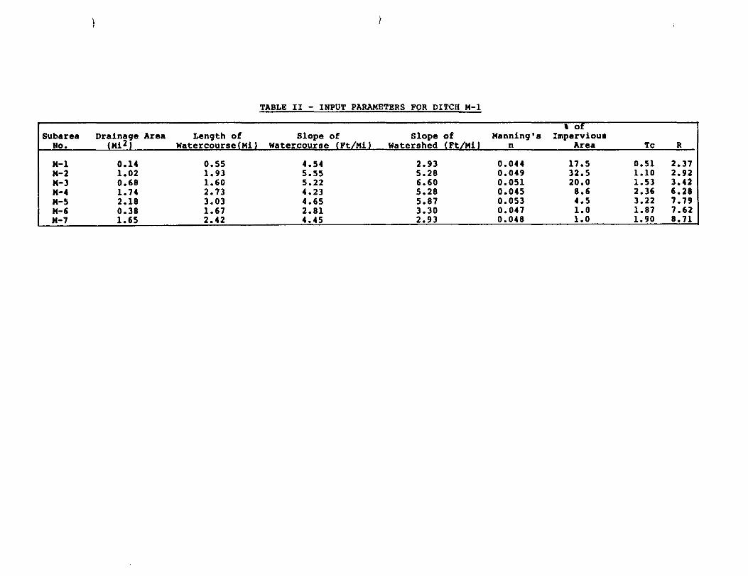
TABLE II - INPUT PARAMETERS FOR DITCH M-1
, 0
Subarea Length of Slope of Slope of Manning's Impervious No. Watercourse Mi Watercourse Ft Watershed Ft n Area Tc R
M-1 0.14 0.55 4.54 2.93 0.044 17.5 0.51 2.37 M-2 1.02 1.93 5.55 5.28 0.049 32.5 1.10 2.92 M-3 0.68 1.60 5.22 6.60 0.051 20.0 1.53 3.42 M-4 1.74 2.73 4.23 5.28 0.045 8.6 2.36 6.28 M-5 2.18 3.03 4.65 5.87 0.053 4.5 3.22 7.79 M-6 0.38 1.67 2.81 3.30 0.047 1.0 1.87 7.62 M-7 1.65 2.42 4.45 2.93 0.048 1.0 1.90 8.71

TABLE III - INPUT PARAMETERS FOR NEW BAYOU
, of Subarea Drainaqe Area Lenqth of Slope of Slope of Manninq's Impervious
No. (Mi2) Watercourse(Mi) Watercourse (Pt/Mi) Watershed (Pt/Mi) n Area Tc R
N-1 1.50 2.20 2.28 2.64 0.049 1.0 1.98 15.70 N-2 2.40 3.10 2.50 3.30 0.046 1.0 2.48 14.02-N-3 1.75 2.95 2.96 3.77 0.047 1.0 2.81 9.93 N-4 1.33 1.67 1.35 3.30 0.045 1.0 2.28 9.06 N-5 1.56 2.95 1.19 2.64 0.047 1.0 2.74 14 .42

TABLE IV - INPUT PARAMETERS FOR CHOCOLATE BAYOU
, of Subar.a Drainaq. Area Lenqth of Slope of Slope of Manninq'. Imperviou.
No. (Mi 2 ) Watercourse(Mi) Watercourse (Pt/Mi) Watershed (Pt/Mi) n Area Tc R
1 1.39 3.40 3.29 3.77 0.048 1.0 3.0 15.00 2 5.92 5.38 2.67 2.64 0.054 1.2 3.42 19.50 3 12.46 6.52 3.03 4.80 0.064 3.2 6.04 17.31 4-1 15.07 6.97 2.75 2.64 0.074 1.8 4.97 32.80 4 13.42 9.47 2.77 3.77 0.068 1.0 7.44 26.31 5 2.76 3.71 3.64 3.77 0.085 1.0 4.84 17.54 6 7.47 8.71 3.01 2.64 0.060 1.0 4.74 24.96 7 0.98 1.59 3.62 3.52 0.081 1.0 2.74 10.35 8 14.13 8.33 2.75 3.30 0.050 1.0 4.96 20.11 9 14.40 6.52 2.19 3.30 0.830 1.0 6.92 28.08
10 14.20 8.03 2.62 3.50 0.080 2.0 6.88 26. OS I
11 11.50 12.57 2.09 2.64 0.078 1.0 8.00 42.13 12 3.69 4.02 1.87 4.40 0.066 2.9 5.30 16.15 13 7.96 6.97 3.34 4.80 0.040 1.0 4.43 12.70 14 11.92 10.23 3.03 2.93 0.039 4.0 3.81 18.18 15 12.72 7.20 3.58 4.40 0.039 1.0 3.90 13.26
- -- ---
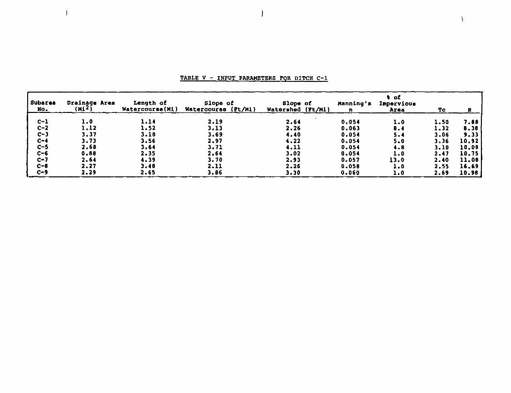
TABLE V - INPUT PARAMETERS FOR DITCH C-l
, of ,
Subarea Drainage Area Length of Slope of Slope of Manning's Impervious No. (Mi 2 , Watercourse(Mil Watercourse (Pt/Mil Watershed (Pt/Mi) n Area 'l'c R
C-1 1.0 1.14 2.19 2.64 0.054 1.0 1.50 7.88 C-2 1.12 1.52 3.13 2.26 0.063 8.4 1.32 8.38 C-3 3.37 3.18 3.69 4.40 0.054 5.4 3.06 9.33 C-4 3.13 3.56 2.97 4.22 0.054 5.0 3.36 10.92 C-5 2.68 3.64 3.71 4.11 0.054 4.8 3.10 10.09 C-6 0.88 2.35 2.64 3.02 0.054 1.0 2.47 10.75 C-7 2.64 4.39 3.70 2.93 0.057 13.0 2.40 ll.08 C-8 2.27 3.48 2.11 2.26 0.058 1.0 2.55 16.69 C-9 2.29 2.65 3.86 3.30 0.060 1.0 2.69 10.98 ------ -- -- ----- --~ ---- ----- -- ---- ---- ------- ----- ---------- ------- - ---- -- -- -

T~B~E VI - INPUT PARAMETERS FOR HEC-l MODEL
SUB AREA DRAINAGE LENGTH OF SLOPE OF SLOPE OF MANNING'S , OF Tc R" NO. AREA WATERCOURSE WATERCOURSE WATERSHED n IMPERVIOUS
(Mi2) (Mi) , (Ft/Mji.) (Ft/MiJ AREA
HALLS BAYOU
1 1.44 1.33 3.8 4.4 0.05 1 1.93 5.9 2 0.47 0.53 2.8 3.96 0.05 1 1.16 3.94 3 2.2 1.8 3.0 3.30 0.05 1 2.01 8.17
fIl 4 6.7 3.6 2.5 3.17 0.065 1 6.00 21.6 Z 0 5 8.59 5.2 2.2 3.50 0.065 1 5.18 19.6
ri 6 10.42 7.4 1.6 2.40 0.065 1 5.3 29.6 7 3.2 3.0 2.0 3.3 0.04 1 3.4 13.5
.~ ~.HIG.G~~ CREEK ;"0 ~~ 1 1.32 2.1 3.8 4.4 0.05 1 2.49 7.61 $or-! 2 0.17 1.9 3.7 4.4 0.05 1 2.37 7.24 ;;I" 3 0.44 1.0 4.0 4.4 0.05 1 1.61 4.91 IC ... . ~
DI(:KINSON BAYOU Z P 1 0.06 0.75 2.7 2.7 0.05 1 1.09 5.45
2 0.20 0.65 3.1 4.0 0.05 1 1.27 4.30 3 0.18 0.75 2.7 2.5 0.05 1 1.0 5.56
DITCH Q--4
1 1.18 1.5 3.6 4.4 0.05 2 2.05 6.18 2 0.76 1.4 3.55 3.5 0.05 2 1.71 6.47 3 1.54 2.7 2.46 3.5 0.05 1 2.83 10.69 4 0.64 1.6 2.85 3.17 0.05 1 2.1 7.45 5 0.72 1.6 2.23 3.17 0.05 2 2.12 7.49
Control
0 1 2 3 4 5 6 7
M-l M-2 M-3 M-4
M-5 M-6
M-7
8
N-l N-2 N-3 N-4 N-5
9
10
I6DLI vu - ti2:iI6liSi B6XQY IfAnBSlIl1:!
Drainaqe 25-Year 100-Year Area (Mi 2 , nf.",h ..... a .. (CPS) nf·" '(CPS I T.,.,,, ... " i,.,n
6.91 831 1080 At County Line 11.05 1203 1623 At SH 288 16.65 1801 2437 At PM 1128 21.91 2159 3096 Near SH 6 27.66 2354 3374 At M.P.R.R. 30.77 2286 3283 At SH 35 33.67 3011 3900 At CR 160 36.10 3234 4191 At confluence
w/Ditch M-l
(The above flows are on Mustanq Bayou)
0.14 142 178 At w. Dumble Rd. 1.16 974 1245 At South St. 1.84 1051 1252 At SH 35 3.58 1678 2040 At Pipeline
Crossinq 5.76 1960 2451 At BRA Canal 6.14 2007 2299 At M.P.R.R.
(Diversion Point) 7.79 1399 1601 At confluence
w/Mustanq Bayou
(The above flows are on Ditch M-l)
47.52 4832 6088 At confluence loll Persimmon Bayou
(The above flow is on Mustanq Bayou)
1.50 1297 1537 At M.P.R.R. 3.90 1632 2034 At BRA Canal 5.65 1676 2131 At M.P.R.R. 6.98 1743 2216 At M.P.R.R. 8.54 1841 2363 At confluence
w/Mustanq Bayou
(The above flows are on New Bayou, flows include diversion from Ditch M-l and C-l)
58.04
62.12
6799
7101
8649
9039
(The above flows are on Mustanq Bayou)
At confluence w/New Bayou At confluence loll Persimmon Bayou
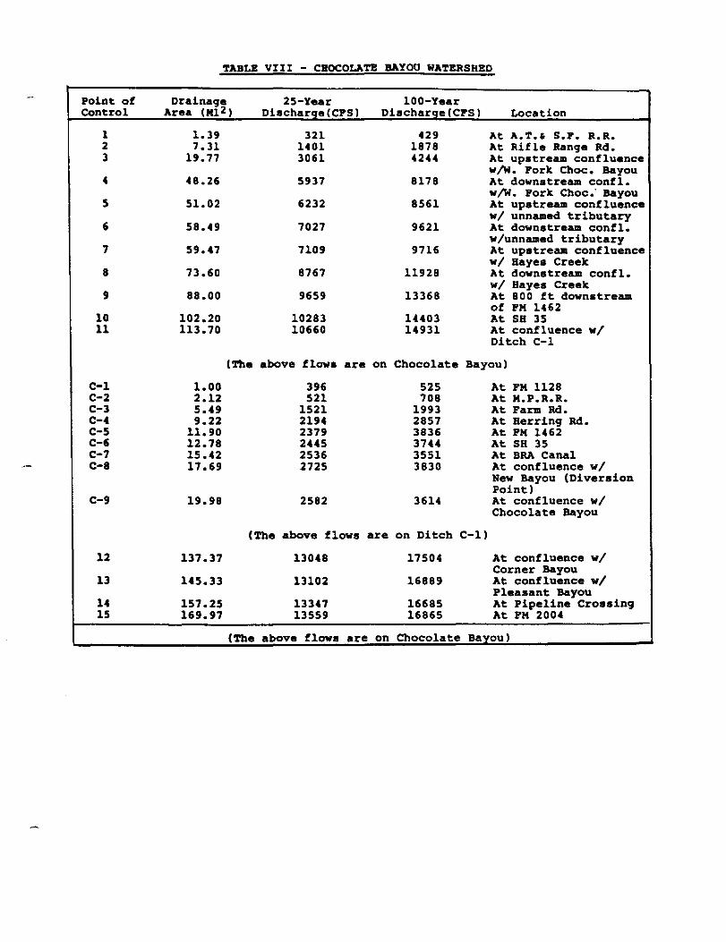
TABLE VIII - CHOCOLATE BAYOU WATERSHED
Point ot Drainage 25-Year 100-Year Control Area (Ml2) Discharge(CPS) Diacharge(CPS) Location
1 1.39 321 429 At A.T.' S.P. R.R. 2 7.31 1401 1878 At Rifle Range Rd. 3 19.77 3061 4244 At upstream confluence
w/W. Pork Choc. Bayou 4 48.26 5937 8178 At downstream confl.
w/W. Pork Choc.· Bayou 5 51.02 6232 8561 At upstream confluence
wi unnamed tributary 6 58.49 7027 9621 At downstream contl.
wlunnamed tributary 7 59.47 7109 9716 At upstream confluence
wi Bayes Creek 8 73.60 8767 11928 At downstream contl.
wi Hayes Creek 9 88.00 9659 13368 At 800 ft downstream
of PM 1462 10 102.20 10283 14403 At SH 35 11 113.70 10660 14931 At confluence wi
Ditch C-l
(The above tlows are on Chocolate Bayou)
C-l 1.00 396 525 At PM 1128 C-2 2.12 521 708 At M.P.R.R. C-3 5.49 1521 1993 At Farm Rd. C-4 9.22 2194 2857 At Herring Rd. C-5 11.90 2379 3836 At PM 1462 C-6 12.78 2445 3744 At SH 35 C-7 15.42 2536 3551 At BRA Canal C-8 17.69 2725 3830 At confluence wi
New Bayou (Diversion Point)
C-9 19.98 2582 3614 At confluence wi Chocolate Bayou
(The above flows are on Ditch C-l)
12 137.37 13048 17504 At confluence wi Corner Bayou
13 145.33 13102 16889 At confluence wi Pleasant Bayou
14 157.25 13347 16685 At Pipeline Crossing 15 169.97 13559 16865 At PM 2004
(The above tlows are on Chocolate Bayou)

CONTROL POINT
1 2 3 4 5 6 7
1 2 3
1 2 3
1 2 3 4 5
NOTE:
TABLE IX - HEC-l RESULTS
DRAINAGE 25-YEAR 100'-YEAR LOCATION AREA DISCHARGE DISCHARGE
(Mi2) (CFS) (CFS) >
HALLS BAYOU
1.44 710 933 CR 159 1.91 998 1310 CR 164 4.11 1807 2114 Canal
10.81 2775 3546 19.40 4297 5570 Halls Bayou Rd. 29.82 5539 7292 Cloud Bayou 33.02 6029 8053 Oak Ditch
CHIGgER CREEK
1.32 530 701 CR 98 2.09 703 993 CR 99 2.53 689 (440) 1022 (720) Dist. Boundary
DICKINSON BAYOU
0.06 32 42 Hwy 35 0.26 129 170 Canal 0.44 213 281 County Line
DITCH D-4
1.18 561 (800) 738 (1020) CR 144 1.94 884 (1120 ) 1172 (1450) R.R. 3.48 1346 (1580) 1780 (2060) R.R. 4.12 1539 (1770) 2065 (2350) Hwy 35 4.84 1481 (1720 ) 1986 (2270) County Line
Numbers in ( ) show the adjusted flow due to the diversion on Chigger Creek to Ditch D-4.
SNOWDEN ENGINEERING, INC. House"" • Pearland. T ex ..

LEGEND
--
COUNTY I()UC)ARY
DRAINAGe: DISTRICT L.
.. --
_-.cT ..
-
---
SNOWDEN ENGINEERING, INC. COIOS\JL TlIOG Dl5tNUM
HOUSTOtI - I'£AJIUJII, nxAS
BRAZORIA COUNTY
DRAINAGE DISTRICTS MAP
... ~ .,-•• , .. ,.. NOV.II'. _. t

n: _
·C~
---~----_ ... -----_ ..
} , , ,
1 I \
BAYOU
IUVUTCIII
COUOOTT
-./' ...
SNOWDEN ENGINEERING. INC. CONSUl. TtNG ENG IMEERS
HOUSTON - PEARLAND. TEXAS
DRAINAGE BOUNDARIES
_"'.1 "-0" DAn. NOV. I •••
Master Drainage Plan Report on Mustang Bayou, Chocolate Bayou, Ditch C-1, Ditch M-1 New Bayou,
Halls Bayou, Chigger Creek, Ditch 0-4 and Dickinson Bayou Watersheds
Volume 1 of 3 Contract #FP 8-483-519
The following maps are not attached to this report. They are located in the official file and may be copied upon request.
Map 1 - Mustang Bayou Watershed Subwatershed Exhibit III A Mustang Bayou watershed & Subwatershed Exhibit III B Chocolate bayou Watershed - Exhibit IV Watershed & Subwatershed - Exhibit V Mustang Bayou & New Bayou - Exhibit VI Flood Limits on Chocolate Bayou Exhibit VII Flood Limits - Exhibit VIII Mustang Bayou Exhibit IX Exhibit IX Cont. Exhibit X Exhibit XI Exhibit XII Exh ibit XIII Exhibit XIV Exhibit XVI Exhibit XVII

Mustang Bayou Watershed Exhibit XVIIIA Exhibit XVIIIB Chocolate Bayou Watershed Exhibit XIX Exhibit XX Mustang Bayou Exhibit XXI Exhibit XXII Exhibit XXIV Exhibit XXV Exhibit XXVI Exhibit XXVII Exhibit XXVIII Exhibit XXIX
Please contact Research and Planning Fund Grants Management Division at (512) 463-7926 for copies.