masonry revision 2007 08
DESCRIPTION
it is very important oneTRANSCRIPT

Masonry - Revision
March 2008

Vertically loaded masonry

Examples• Problem 1• An internal loadbearing masonry wall
has a clear vertical span of 2.5 m and supports a rigid continuous floor together with loads transferred from upper storeys.
• Unfactored vertical loads acting on this masonry are:
• Dead load - 127.5 kN/m• Imposed load - 15.0 kN/m• It is necessary to use a 190 mm high x
140 mm wide aggregate concrete block. What strength block, would be required to take the applied loads?
• Assume designation (iii) mortar is to be used.
• Assuming normal control of manufacture and construction m = 3.5
2500
mm
End conditions
Wall part of 4 storey building
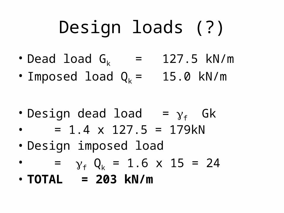
Design loads (?)
• Dead load Gk = 127.5 kN/m• Imposed load Qk = 15.0 kN/m
• Design dead load = f Gk • = 1.4 x 127.5 = 179kN• Design imposed load• = f Qk = 1.6 x 15 = 24• TOTAL = 203 kN/m

Capacity reduction factor Depends on – slenderness ratio and eccentricity of load
• Slenderness ratio = effective height/effective thickness
• 24.3.2 Effective height. 24.3.2.1 Walls• Effective height of a wall :• a) 0.75 times the clear distance between lateral supports which provide
enhanced resistance to lateral movement; or• b) the clear distance between lateral supports which provide simple
resistance to lateral movement.
• Wall clamped in position - Enhanced restraint at top and bottom• Effective height = hef = 2.5 x 0.75 = 1.875 m• Effective thickness = Actual thickness • = tef = t = 0.14 m
OK 2 < 13.39 = 0.14
1.875 =
t
hRatioS
ef
ef 7

Capacity reduction factor Depends on – slenderness ratio and eccentricity of load
• Eccentricity of load.
• Internal wall with no eccentric loads, so eccentricity = 0.00mm
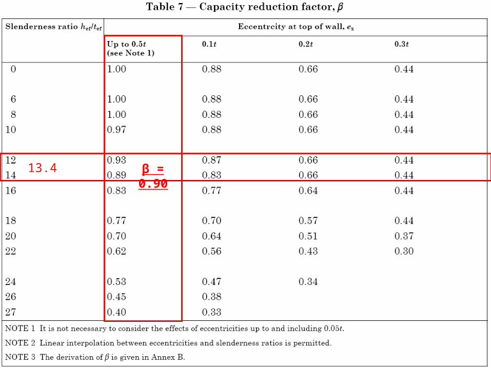
13.4 β = 0.90

Design vertical load capacity/unit length. (Clause 28.2.2)
• Aspect ratio of unit = 190/140 = 1.36
t
N = f or
f.t. = N m
km
k
mmN/ 5.64 =10 x 140 x 0.9
3.5 x 10 x 203 = f 2
3
3
k
Masonry characteristic strength is known.
What units are required?
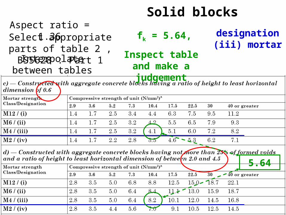
Solid blocksAspect ratio = 1.36
fk = 5.64, designation (iii) mortar
Interpolate between tables
Inspect table and make a judgement
5.64
Select appropriate parts of table 2 , BS5628 : Part 1

Try blocks of strength 10.4N/mm2
• fk = 6.33N/mm2 ≥ 5.64N/mm2 so OK
)1.42.8)6.00.2
6.036.11
( x )(
)( + 4. = f k
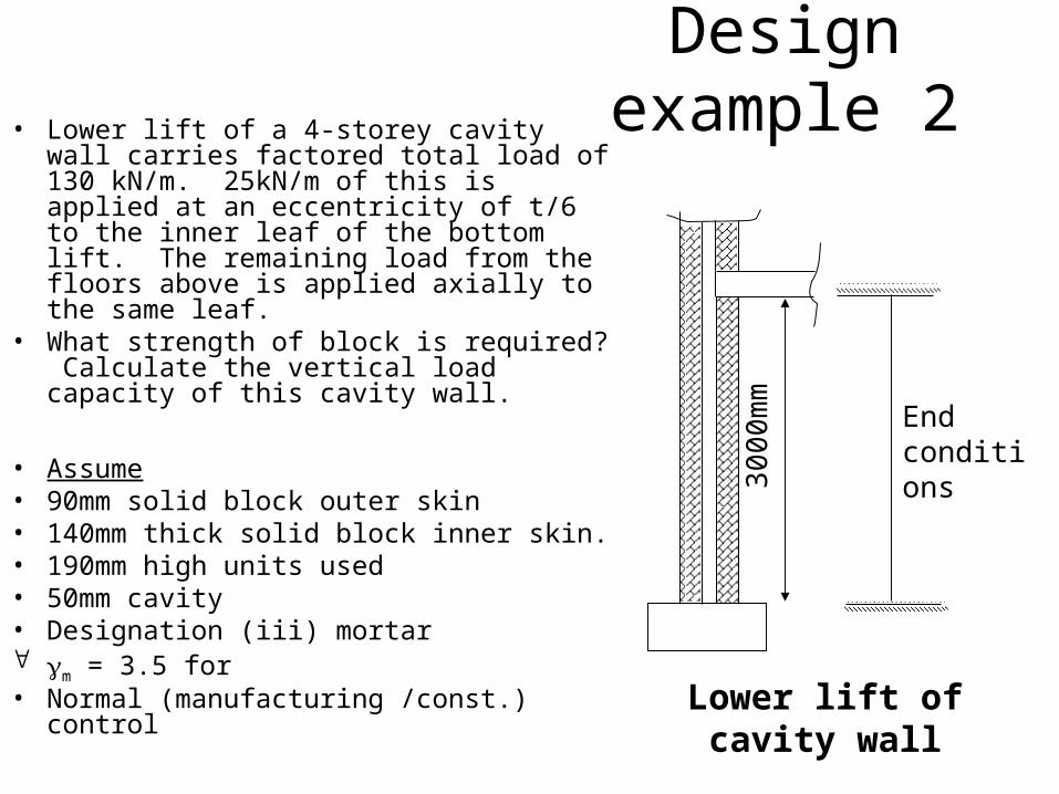
Design example 2• Lower lift of a 4-storey cavity wall carries
factored total load of 130 kN/m. 25kN/m of this is applied at an eccentricity of t/6 to the inner leaf of the bottom lift. The remaining load from the floors above is applied axially to the same leaf.
• What strength of block is required? Calculate the vertical load capacity of this cavity wall.
• Assume• 90mm solid block outer skin• 140mm thick solid block inner skin.• 190mm high units used• 50mm cavity• Designation (iii) mortar m = 3.5 for • Normal (manufacturing /const.) control
End conditions
3000
mm
Lower lift of cavity wall

SolutionCapacity reduction factor
depends on ecc’n of applied load & slenderness ratio
• Eccentricity of 1st floor loading • ex = t/6 = 140/6 =23.3mm• BRE guidance – Lecture notes
• Ecc’n of Resultant total load. • Moments about wall centre
• 130x = 25 x 23.3• So x = 4.48mm = 0.03t• Less than 0.05 t (See Table 8).
23.3mm
105kN 25kN
xmm
Resultant 130kN

Slenderness ratio = effective height/ effective thickness = hef/tef
• Effective height :
• 24.3.2 Effective height. 24.3.2.1 Walls• a) 0.75 times clear dist between lateral supports
which provide enhanced resistance to lateral movement; or
• b) clear dist between lateral supports which provide simple resistance to lateral movement.
• Effective height = 0.75 x 3000 = 2250mm
• Effective thickness : • Greatest of • 2/3(t1 + t2) = 2/3(140 + 90) = 154mm• t1 = 140mm• t2 = 90mm
• Slenderness ratio = 2250/154.1 = 14.6
End conditions
3000
mm


14.6 β = 0.872

Design vertical load capacity/unit length. (Clause 28.2.2)
t
N = f or
f.t. = N m
km
k
mmN/ =10 x 140 x 0.
3.5 x 10 x = f 2
3
3
k 77.386
130
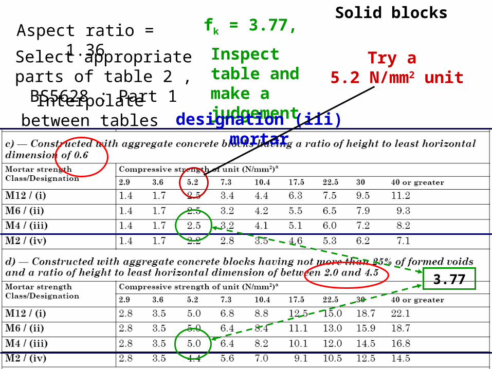
Solid blocksAspect ratio = 1.36
Select appropriate parts of table 2 , BS5628 : Part 1
Interpolate between tables
fk = 3.77,
Inspect table and make a judgement
designation (iii) mortar
3.77
Try a 5.2 N/mm2 unit

Try blocks of strength 5.2N/mm2
• Aspect ratio of unit = h/t = 190/140 = 1.36• Interpolating between Tables 2(c-d), BS 5628
• But 3.86 ≥ 3.73N/mm2 so OK• Use 5.2 N/mm2 unit in wall
2/86.3)5.20.5(6.02
6.036.15.2 mmNfk
kN f.t.
= NcapacityloadverticalActualm
k 3.13410005.3
86.314087.0

Laterally loaded masonry walls

Basic design example
H=L
L
Free edge
Simply supported
Determine the required thickness of a single leaf wall supported as shown above using the following criteria:

Basic design example• Characteristic wind load = 0.45 kN/m2
• Height of wall to free edge = 4.5 m• Length of wall between restraints= 4.5 m• Conc. blocks (solid) strength = 7.3 N/mm2
• Normal category const’n control• Category I or II units• Panel not providing stab. to struct.
γf = 1.2 [Clause 18(b)]• Ignore effects of self weight
γm = 3.0
[Table 4]

Basic design example - Flexural loading
• The design bending moment per unit height of the wall is given by the following expression (Clause 32.4.2).
L W = m 2fk
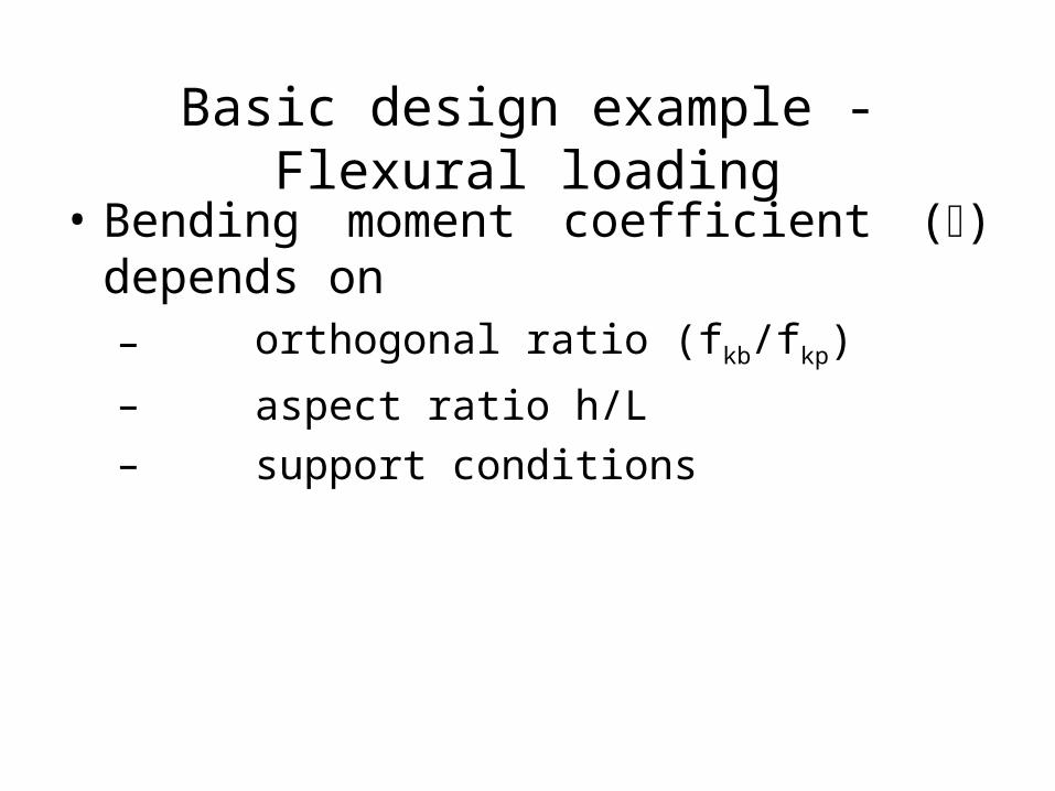
Basic design example - Flexural loading
• Bending moment coefficient () depends on– orthogonal ratio (fkb/fkp)
– aspect ratio h/L– support conditions

Basic design example - Orthogonal ratio - (fkb/fkp)
• Try a 7.3N/mm2 block, 190mm thick
• Determine [fkb and fkp] (Table 3)
• fkb for 100mm wide 7.3 N/mm2 = 0.25
• fkb for 250mm wide 7.3 N/mm2 = 0.15
• fkb for 190mm wide block, = 0.19
(by linear interpolation)

Basic design example - Orthogonal ratio
• fkp for 100mm wide 7.3 N/mm2 = 0.60
• fkp for 250mm wide 7.3 N/mm2 = 0.35
• fkp for 190mm wide block, = 0.45
(by linear interpolation)

Basic design example - Orthogonal ratio
0.42 = 0.45
0.19 =
f
f
kp
kb
Orthogonal ratio = fkb/fkp

Basic example - Aspect ratio
1.0 = 4.5
4.5 =
L
hAspect ratio =

Moment coefficients () Table 8
• From BS 5628 Table 8A• Support conditions-simple• for h/L = 1.0
α = 0.083 with μ = 0.5α = 0.087 with μ = 0.4
• Therefore by linear interpolation• α = 0.0862 when μ = 0.42
μ (required) = 0.42

Applied design moment per unit height
• Since Wk = 0.45 kN/m2 ,
• γf = 1.2,
• L=4.5
• α = 0.0862
m = 0.0862 x 0.45 x 1.2 x 4.52
= 0.943 kNm/m

Design moment of resistance.(Clause 32.4.3)
• For a panel bending in two directions
m
kp Zf =M
Now, fkp = 0.45, t = 190
then M = 0.45 x 1902 x 10-3
3.0 x 6 = 0.903 kNm/m (<0.943)
[Not OK]

Applied moment(Second try)
• Using a 215 block
• fkb = 0.17, fkp = 0.41
• μ = 0.17/0.41 = 0.41
• α = 0.0866
• Hence m = 0.947 kNm/m

Design moment of resistance(Second try)
• Now, fkp = 0.41, t = 215
• M = 0.41 x 2152 x 10-3
3.0 x 6
= 1.053 kNm/m (> 0.947) [Therefore OK]• Therefore use block of thickness 215mm (7.3
N/mm2)
For a panel bending in two directions
m
kp Zf =M
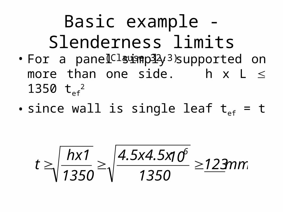
Basic example - Slenderness limits
(Clause 32.3)• For a panel simply supported on more than one side. h x L 1350 tef
2
• since wall is single leaf tef = t
mm123 1350
104.5x4.5x
1350
hx1t
6

Basic example - Slenderness limits
(Clause 32.3)• In addition no dimension shall exceed 50 tef. since h and L both = 4.5 then
mm90 50
104.5x t
3

Basic example - Shear design(Clause 21)
• Consider the wind load to be distributed to the supports as shown below
4.5m
4.5m
45o

Basic example - Shear design(Clause 21)
Total load to support = γfWkx(loaded area)
Total shear along base
= 1.2 x 0.45 x {(4.5 x 2.25)/2} = 2.734 kN
Assume this is a udl along base
Design SF per metre run, is
kN 0. = 5
2.734 = 61
.4
Basic example - Shear design(Clause 21)
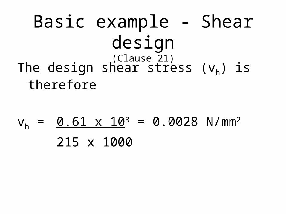
The design shear stress (vh) is therefore
vh = 0.61 x 103 = 0.0028 N/mm2
215 x 1000

Basic example - Shear design(Clause 21)
Charac. shear strength (fv) from clause 21
= 0.35 + 0.6 gd
Ignoring self weight, characteristic strength
fv = 0.35 N/mm2

Basic example - Shear design(Clause 21)
• Design shear stress (vh) limited so
mv
vh
f v
vh = 0.0028 N/mm2
mmN/ 0.14 = 2.5
0.35 =
f 2
mv
v
Therefore OK along base

Basic example - Shear design(Clause 21)
Total shear to each vertical support
= 1.2 x 0.45 x 2.25 (2.25 + 4.5) = 4.10 kN 2
Assume this load to be a udl up the sides, design shear force per metre run
= 4.10 = 0.91 kN
4.5

Basic example - Shear design(Clause 21)
• Use 2 mm thick anchors into dovetail slots in column.• Charac. strength of each tie = 4.5 kN, (Manuf. Data)
• Place ties at 900 mm centres. Assume m = 3.0.
• Design load resistance per metre run of wall
= 4.5 x 1000 = 1.67 kN > design shear force
3.0 900
Vertical shear adequate

Tutorial - Problem 1
Continuous supports
h
L
Free edge
Simple supports
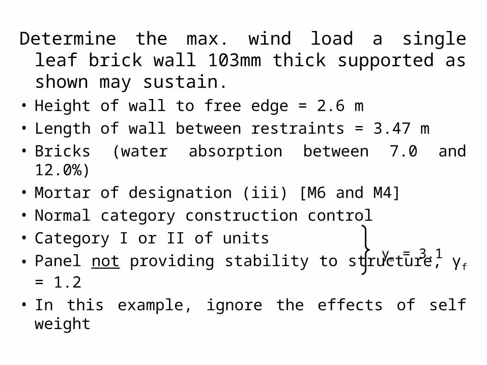
Determine the max. wind load a single leaf brick wall 103mm thick supported as shown may sustain.
• Height of wall to free edge = 2.6 m• Length of wall between restraints = 3.47 m• Bricks (water absorption between 7.0 and 12.0%)• Mortar of designation (iii) [M6 and M4]• Normal category construction control• Category I or II of units
• Panel not providing stability to structure, γf = 1.2
• In this example, ignore the effects of self weight
γm = 3.1
Tutorial - Problem 2• As for problem 1 but include self weight
Density of the brickwork is 22.0kN/m3
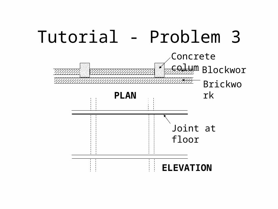
Tutorial - Problem 3
Joint at floor
Concrete columns
Blockwork
BrickworkPLAN
ELEVATION

• Design a cavity wall, 4.5m by 3.375m high to withstand a wind pressure of 0.6 kN/m2.
• Outer leaf - Clay brickwork running past supporting columns – (Water absorption > 12%) – (mortar designation (iii)). [Mortar M4 or M6]– Density 17.0kN/m3
• Inner leaf Blockwork abutting the columns with a soft control joint. – Thickness of leaves = 100 mm.– Density of blockwork = 10.0 kN/m3.

Tutorial - Problem 4
4.0m
1.5m
1.0m
1.5m
1.5m 1.0m 1.5m
Opening
Continuous supports
Design a single leaf wall panel, 4m long by 4m high, with a centrally placed 1.0 x 1.0m window to resist a characteristic wind pressure of 0.6 kN/m2. All edges are considered to be fixed.
γm = 3.0 γf = 1.2
10.4 N/mm2 blocks

Concentrated loads

Question Concentrated loads.
• A 300mm wide x 500mm deep reinforced concrete beam is to be built into a 100mm thick masonry wall. The masonry is assumed to comprise 7.3N/mm2 concrete blocks in designation (iii) [M4] mortar. The blocks are 215mm high and the partial factor for materials has been assessed to be 3.5. The reaction at the end of the beam is 50.0kN and a uniformly distributed load of 20.0kN/m exists along the wall at the level of the top of the beam. The density of the concrete blockwork is 20kN/m3, and the wall is supported 2400mm below the beam on a level slab. For design purposes, assume the wall is pinned at the top and bottom. Is the blockwork selected adequate?
• Can you improve on this design? Discuss what would happen if the wall was 140mm wide?
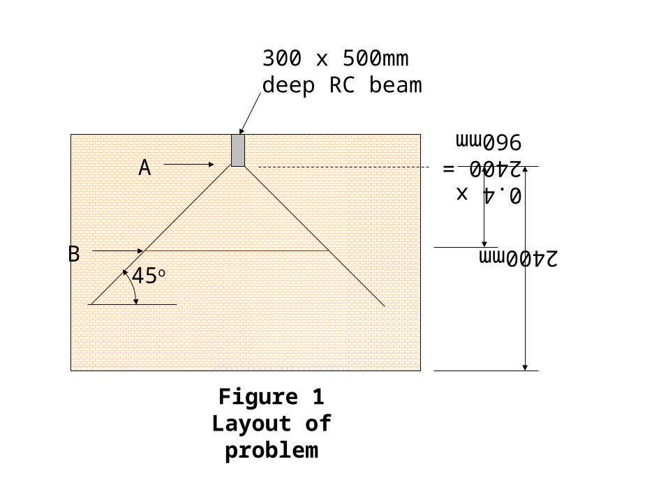
45o
2400mm
0.4 x 2400 = 960mm
A
B
Figure 1Layout of problem
300 x 500mm deep RC beam

Solution.• Check at level A.• Masonry strength [ht/least dim of blocks • = 2.15] = 6.4N/mm2 Table 2 BS5628 Part 1
• Figure 4 – bearing type 1
• Enhance strength by 1.25, strength • = 6.4 x 1.25 = 8.0N/mm2
• Design strength of masonry • = 8.0/3.5 = 2.28N/mm2
• Stress imposed on masonry • = (50 x 103)/(300 x 100) = 1.67N/mm2 so OK

• Check 0.4h m down.• Masonry strength = βtfk/γm • Determination of β : • Depends on :- • Slenderness ratio = effective height/effective thickness • = 2400/100 = 24• Eccentricity of load. • This needs to be determined 0.4m down. • Axial load [udl along wall over 0.960 x 2 + 0.3 = 2.22m] • = 20 x 2.22 = 44.4kN• Axial load from 1460mm of masonry along 2.22m • = 20 x 0.1 x 1.46 x 2.22 = 6.48kN• Moments about centre line.• 50 x 16.67 = 100.88 x e, so e = 8.3mm = 0.08t• Determination of β : From table 7 and by interpolation• β = 0.47 + 0.4 x 0.03 = 0.482• Stress capacity at 0.4m down = βtfk/γm = 0.482 x 6.4/3.5 =
0.88N/mm2
• Applied stress in masonry = (100.88 x 10³)/(2220 x 100) • = 0.45N/mm2 so OK
50.88kN 50.0kN
R = 100.88kN
e
t/6=16.7mm
Other areas
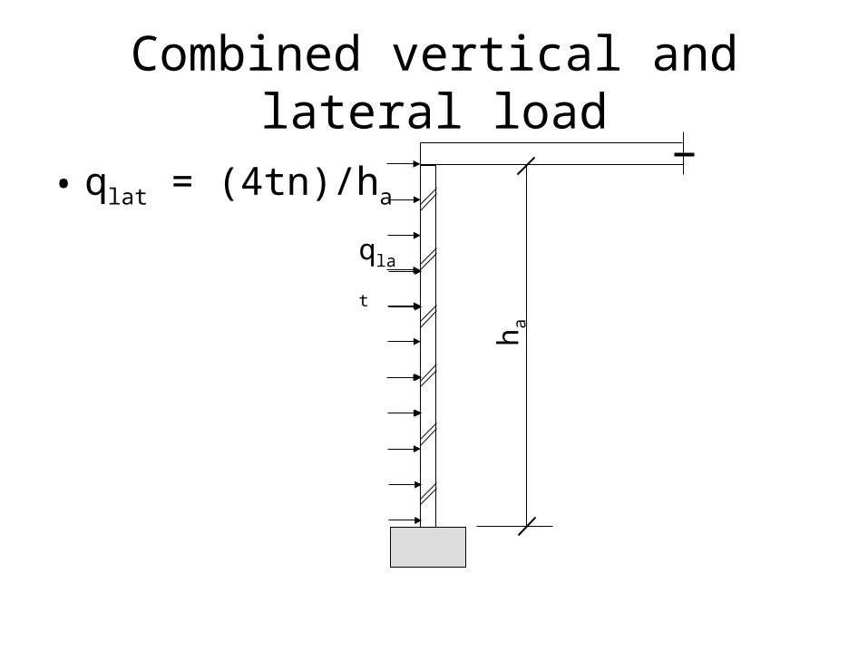
Combined vertical and lateral load
• qlat = (4tn)/ha
h a
qlat
Diaphragm walls
• When would they be used.
• What are the principles of their design
• Advantages and disadvantages
Retaining walls
• Drainage
• Sulphate and frost protection
Reinforced masonry
• Pocket walls
• Infill walls
• Reinforcement
• Details
• Max and min reinforcement