masonry infill panels subjected to cyclic …2)0122.pdfreinforced concrete it has been shown that...
TRANSCRIPT

122
1. SYNOPSIS The pres ence of an infill panel within
a frame greatly increases the stiffness of the structure as compared with the bare frame but in the process a less ductile and a degrading stiffness behaviour is obtained. Although the panel may be isolated from the frame, there are many instances where this is not the case and so a study of the behaviour of infill-panel frames subjected to the large lateral loads and deformations associated with earthquakes is essential.
A test programme of three frames, one unfilled, one filled with unreinforced but grouted hollow bricks and one filled with reinforced grouted hollow bricks is reported. The panels, in nominal 4" reinforcing bricks , were 3'-10" high by 5 1 -11 M long within a reinforced concrete frame of 8" x 6" section. An in-plane horizontal load was applied to the top of the single-storey single-bay structure. The test results confirm existing analysis methods for stiffness calculation but the strengths of the infill panel frames were not well predicted by these methods. In particular, the behaviour of the panels under large static cyclic loading is studied. The wall performances were quite ductile but with the low recycling stiffness which is common to shear and diagonal tension structures.
2. BEHAVIOUR OF MASONRY INFILL PANELS
Under lateral loading infill panel structures go through a number of changes in behaviour as load and deformation increase. Any factor which alters the frame and/or panel stiffness or strength will change the details of the behaviour pattern. The number of storeys and bays, which may be filled or not filled, and the presence of wall openings, all have considerable effect.
The various modes of behaviour and a brief explanation of existing analysis and design methods are discussed in the following sections.
2.1 Initial Uncracked Mode
Providing there is no gap between the frame and the infill wall, the total system will act, at least initially, as a single monolithic member. Where the frame is in reinforced concrete it has been shown that in normal construction conditions this mode may carry loads up to 50% of the ultimate load of the system. Hence a study of the uncracked mode behaviour will give a good
* Structural Engineer, Brickell, Moss Rankine and Hill, Wellington.
** Reader in Civil Engineering, University of Canterbury, Christchurch.
indication of conditions under normal service loads.
Standard elastic structural theory may be used to analyse the structure during the initial uncracked mode. Often referred to as "the beam analogy", the horizontal deformations at a floor may be determined by considering the flexural and shear deformations of the total system. A design approach is given in reference (1).
Where there are large openings in the panels the beam analogy can no longer be applied simply. If the openings are of the same size and distributed uniformly, the structure becomes a system of walls linked by deep beams and it may be analysed using laminar analysis of coupled shear walls(2) . When there is no regularity a finite element analysis may be used (̂ ' .
The duration of the mode depends greatly on the bond between the frame and wall. The use of shear connectors between frame and panel has been shown to maintain the initial uncracked mode up to a higher load but they may produce premature cracking within the panel.
Where flexure predominates the system acts as a vertical cantilever and horizontal flexural cracks may open on the tension side of frame and panel. Due to the differences in the moduli of frame and panel and the limited shear strength of the frame-panel interface a vertical crack usually develops along the interface in this area and this terminates the initial uncracked mode. When shear is relatively more important cracking on the diagnonally opposite interfaces may also occur due to deflection incompatibility between frame and panel.
2.2 Behaviour after Boundary Cracking
As the frame and panel deflect differently , eventually they will separate except at the corners at the end of the compression diagonal. From now on the infill effectively acts as a diagonal strut within the frame and an analogous frame can be postulated, see Fig. 1. M. Holmes (5), for steel frames with concrete infilling, suggested that the width of the strut be taken as one-third of the diagonal length L of the panel. A comprehensive analysis by Smith and Carter ( 6 ) indicates that the strut width depends critically on the length of contact between panel and frame and that, in turn, this depends on the relative stiffness of columns and infill, the length/height proportions of infill and the stress-strain relationship of the infill material. As the stiffness of a reinforced concrete column and the stiffness of a masonry panel will change with the extent of cracking the equivalent strut width also alters throughout the
BULLETIN OF THE NEW ZEALAND NAT IONAL SOCIETY FOR EARTHQUAKE ENGINEERING, VOL.9 NO.2. JUNE 1976
M A S O N R Y I N F I L L P A N E L S S U B J E C T E D T O C Y C L I C
I N - P L A N E L O A D I N G
J. M . L e u c h a r s * and J C. S c r i v e n e r * *

123
loading cycle. The authors give a series of graphs for the determination of width and values between L/4 and L/ll are usual.
2.3 Panel Failure Mechanisms
Provided that the frame has sufficient strength, the masonry infill panel subjected to lateral loading may fail in one or a combination of the following modes.
(a) Shear, or sliding, failure along a horiziontal mortar bed.
(b) Diagonal tension cracking through masonry and mortar.
(c) Local crushing of the masonry in a compression corner.
Smith and C a r t e r ^ give curves for the strengths in the shearing and diagonal tension failure modes for panels constructed in solid brick units. To derive these it was necessary to give values to the bond shear strength between masonry and mortar, the coefficient of internal friction between masonry and mortar, and the diagonal tension strength of masonry. As there is insufficient information available on masonry material strengths, their curves can hardly be expected to give more than a guide to infill panel strengths. Further, the presence of reinforcing will enhance the strength in failure modes (a) and (b).
Since masonry is relatively weak in shear and diagonal tension it is unlikely that crushing of the masonry will occur first.
The failure mechanism of the panel appears to be little affected by the frame characteristics. For instance in a series of tests on square masonry diaphragms confined by reinforced concrete frames and loaded in a rig which effectively gave diagonal loads, Esteva'7) found that in all cases the diagonal cracking of the panel preceded that of the frame. This occurred regardless of the frame corner reinforcement or cross section or of the frame diagonal strength considered as an independent member.
2.4 Infill Frame Failure Mechanisms
On the other hand the manner of the infill failure very greatly influences the failure of the frame as it determines the way in which the frame is to be loaded after the panel has cracked or failed.
A University of I l l i n o i s ^ investigation classifies failure mechanisms of frame-wall systems into flexural or shear failure. Fig. 2, reproduced from the Illinois report, idealizes the types of failures obtainable with single storey specimens. In Fig. 2(a), the frame-wall fails with the yielding of the tension column. The formation of a shear crack separating the panel into two parts, as in Fig. 2(b), may precipitate failure of the individual columns in flexure as in Fig. 2(c) where portions of both columns develop hinges, Alternatively, if the flexural strengths of the columns as loaded are such that the shears associated with the plastic hinges developed are greater than their shear strengths, both columns may fail in shear as in Fig. 2(d). Mechanisms are also possible involving combinations of shear and flexural failures in
the columns as in Fig. 2(e). Even after the formation of the shear crack in the panel it is possible that the frame may still yield as in Fig. 2(a).
The panels of the Illinois tests were of length twice the height and were unrein-forced, After panel shear cracking the system behaviour became more dependent on the material and geometrical properties of the reinforced concrete frame which was braced by the segments of masonry wall between the cracks, The authors term the system a "knee braced frame" and give a hypothetical model, Fig, 3(b), based on the characteristic crack pattern of their one-storey specimens Fig. 3(a). The crack pattern indicates that after the shearing cracks formed in the panel the lower portion of the tension column was braced by the bottom portion of the masonry. The upper segment of the wall formed a haunch at the intersection of the compression column with the top beam. There is also a tendency for the unbraced portions of the columns to bend about the wall segments. The braces reduce the effective height of the columns allowing higher leads to be carried. The capacity of the braced columns and the force developed through friction of the wall panel represent the major lead carrying mechanism of the knee braced frame system.
In both the Illinois ( 1 ) and E s t e v a ( 7 )
investigations the infill panels were subjected to static cyclic loads to simulate seismic situations. The Illinois work incorporated five storey-one bay and two storey-three bay specimens, some with openings, in addition to single storey-one bay structures.
3. TEST WALLS AND RESULTS
3.1 Frame Details
Three identical reinforced concrete frames, single storey-one bay, with beam and column sections of 8" x 6" , were, constructed monolithically with reinforced concrete bases of 2'-0" x l'-5" section. The bases were bolted to a strong floor. The panels were 5 s-ll n long by 3'-10" high.
The reinforcing content was determined in the following way. Firstly sufficient longitudinal steel was incorporated in the columns to ensure that a flexural cantilever type failure of Fig. 2(a) could not occur. Then moment and shear reinforcement was provided in the frame for a fully ductile section using ACI 318-71 and the special provisions for seismic design in Appendix A. However the maximum shear reinforcement was carried throughout the full length of the columns in order that a reasonable shear capacity would be available in the event of a "knee braced frame" mechanism occurring. It was considered that the frame shear capacity of the bearing portion of the knee allowing for 4 5 ° dispersion and a triangular load distribution, as assumed by Smith and Carter(6), would be capable of transferring 60 kip to the panel. If the shear distribution as given by Esteva^) was used, this would be considerably more.
The columns and beam were reinforced with 6 No. 5 deformed bars while shear reinforcement of undeformed No. 2's at 2"

1 24
centres was provided in the columns and for the ends of the beam, with the central third of the beam containing No. 2 1s at 4" centres. With the small section size, 8" x 6", it was impossible to provide sufficient stirrups at the knee joints to current design recommendations^) and so three 2" x 8" x V plates were welded to the main bars at the knee.
The average 28-day strength of 12" x 6" cylinders of the concrete was 3600 lb/in 2. Test specimens of the main steel yielded at 41,500 lb/in 2 and failed at 63,200 lb/in 2, while the V diameter reinforcement yielded at 48,000 lb/in 2 and failed at 71,800 lb/in 2/
3.2 Panel Details
The panels were constructed in running bond of reinforcing bricks 8 x 4Vf x 2|" with two 2 V square cores. The brickwork was built up to the frame inside face and the only connection to the frame was by mortar bond.
Unit 1 was the frame alone. For Unit 2 the infill panel was not reinforced but the cores were grout filled. Vertical and horizontal reinforcing, No. 2's at 12" centres was provided in Unit 3. The four horizontal bars were positioned bond beams at courses 1, 5, 9 and 14. A vertical bar was placed in the cores adjacent to the frame and all 6 vertical bars were anchored into the base beam. Again all cores were grout filled.
Mortar and grout average strengths in 4" diameter steel cylinders were 1940 and 1900 lb/in 2 and prisms of masonry, three units high, averaged 3830 lb/in 2 at time of wall tests.
3.3 Testing Procedure
The horizontal load was applied through a load cell and ball joint at the beam mid-height by means of a hydraulic jack. Reactive load was taken to ground by a steel column and angled brace. Provision was made to ensure that the frame-wall could not deflect out of plane.
A number of gauges were used to determine column and beam deflections and strains. A load-deflection plot was automatically recorded using load cell and LVDT extensometer at mid-span of the beam and connected to an X-Y plotter.
After a cycle in the linear range the specimens were loaded to yield or significant cracking, and then recycled at this load or deformation. Cycles at higher displacements were then conducted. The load-deflection curves give the detailed information. Cracking in frame and panel was noted at each load increment.
3.4 Behaviour of Test Specimens
Unit 1, of frame alone, behaved in the expected manner of a flexural frame. At 4 kip the first crack opened on the inside of the loaded corner followed at 5 kip by cracks at the tension column base and on the tension faces of beam and columns. At this point the frame stiffness changed markedly as shown in Fig. 4. The extent of the cracking at 15 kip load, just before first
yield, is shown in Fig. 5. For the remainder of the loading, cracks at the knees and column bases opened but on cycling stable hysteresis loops were obtained and a long plateau at the 20 kip yield load was maintained up to the rig capacity of 5V deformation.
For the initial portions of the tests, Unit 2 with unreinforced panel and Unit 3 with reinforced panel, behaved similarly. Apart from small cracks at the tension column base no significant cracking occurred until 38 kip load for Unit 2 (36 kip for Unit 3) when the panel and frame separated along the whole beam and to within 10" - 12" of the loaded corners along the columns. This boundary cracking occurred without any warning and produced a sudden increase in deflection with accompanying loss of load as the hydraulic loading system reacted. The strain profiles across sections changed abruptly from approximately uniform to approximately flexural.
From this stage onwards the behaviour of Units 2 and 3 differed. The first cracks within the unreinforced panel of Unit 2 occurred at 50 kip in the mortar bed above the first course to within 12" of the columns but the damage to panel and frame at this stage was very minor. At 70 kip in the reverse direction (Fig. 6) a diagonal crack from corner to corner appeared with associated shear cracks above second and fifth courses. The panel diagonal crack caused shear cracking in both columns. As the shear capacity of the unreinforced panel is very low, bearing force in the vicinity of the diagonal crack ends tended to produce further horizontal panel cracks. Each successive crack almost completely relieved the bearing load on that course and applied it to the next course so that the horizontal cracking proceeded down the tension column from the knee to the main shear crack along the fifth course. The effect of this cracking was to make the columns bend in double curvature. The structure at an advanced stage of the test, when the deflection was 0.9", is shown in Fig. 7. The load-deflection curve for the complete test of Unit 2 is given in Fig. 8.
The reinforced panel of Unit 3 did not crack until at 60 kip a diagonal crack from the loaded corner to column base opened. Fig. 9. With increasing deformation further diagonal cracking occurred. Horizontal shear cracks appeared but due to the panel reinforcing they were minor and did not extend greatly. Accordingly the bearing load was distributed evenly down the columns and there was little tendency for cracks to proceed down the tension column. However at an advanced stage of the test. Fig. 10, the loaded corners of the panel were severely cracked and there was tendency for spalling of the brick. Fig. 11 gives the complete load-deflection curves.
A more detailed explanation of the behaviour of the units 'may be found in reference (9).
3 . 5 Stiffness of Units
With Unit 1, the prediction of the stiffness in the uncracked state was 130

1 25
kip/in. and the test gave 108 kip/in. Assuming cracking to mid-section throughout, the cracked stiffness was calculated as 6 5 kip/in. which was the actual stiffness at 7.5 kip just below the working load range of 8 - 12 kip. However cracking to mid-section did not occur until 15 kip and then there were long lengths of the frame, especially at mid-span, where there was little cracking.
Both infill Units 2 and 3 gave test stiffnesses before boundary cracking of 3540 kip/in. compared with the beam analogy prediction of 2450 kip/in. At the onset of boundary cracks the actual stiffnesses of 844 kip/in. for Unit 2 and 734 kip/in. for Unit 3 compare with Smith and Carter' s (6) prediction of 690 kip/in. for both units.
It is surprising to find such comparatively reasonable estimates of stiffness as the material properties of masonry are not well known and stiffness after cracking is always difficult to establish.
3.6 Strength of Units
Unit 1 first yield at column base at 14.5 kip was as predicted but the actual ultimate strength of 22 kip exceeded the prediction of 17.5 kip probably due to the early strain hardening of the reinforcing steel which was found with the steel test specimens.
A crude estimate of the diagonal tension strength 82 kip using Smith and Carter's (7) curves overestimated the actual results of 60 kip for Unit 3 which "failed" in diagonal tension and 70 kip for Unit 2 which "failed" in diagonal tension and shear but had cracked in shear earlier at 50 kip. The shear strength prediction of 64 kip was more accurate.
A very much larger crushing strength than the test value of 68 kip for Unit 3 is predicted by Smith and Carter's work. However the prediction assumes a contact length of 14.4" between panel and frame, whereas in the test the actual distance was approximately 8".' Also, Smith and Carter's crushing failure load R for a concrete infill is
R = at sec 6
where a = contact length along column t = panel thickness 6 - angle between panel diagonal and
horizontal f^ = concrete compressive strength
and this assumes that the load distribution between the frame and panel is linear from a maximum at the corner. The formula had acceptable correlation for concrete infill panel tests. However Units 2 and 3 showed that the corner was more heavily leaded than a linear distribution would depict. ^ \ Assuming a parabolic distribution, Trigo obtained
R = \ at sec 6 f 1
3 m where f^ = masonry crushing strength. Using Trigo 1s formula and the actual contact
length, the predicted crushing strength becomes 63.5 kip.
To calculate the ultimate strength of Unit 2 wall-frame, a mechanism based on the Illinois knee braced f r a m e w a s used, the difference being in the fact that the tension column hinge moved down the column as the tests proceeded. To enable the columns to develop the plastic hinges, the columns must be able to sustain the shears associated with the plastic moments. With the formation of the main shear crack, the limit to which the hinge in the tension column could progress down the column was the top of the fifth course giving an effective length two-thirds that of the bare frame, but on recycling and the gradual deterioration of the masonry below this enabled the "hinge" to drop even further. The shear capacity of the column was just sufficient to take the shear generated when the hinge was at the top of the fifth course. However, in the compression column where the hinge positions were restricted, the effective length of the column was only one-third that of the bare frame. Thus there was not sufficient shear capacity and large diagonal tension cracks appeared in the column. The shear steel here would have to be doubled to resist this shear.
In Unit 2 if the compression column could have sustained the shears and generated the moment capacities of the column, and if the hinge position in the tension column was firstly at the top of the fifth course and then at the column base as it was at final failure, the ultimate strength would be 39.3 kips and 34.9 kips respectively. If however the actual moment capacities as exhibited in Unit 1 were used, the ultimate strengths would be 49.5 kips and 44 kips. All these values were calculated without any account being taken of the shear strength of the panel. The actual capacities of Unit 2 were 50 kips when flexure was at the top of the fifth course in both columns and between 3 5 and 45 kips when hinging was at the bottom of the tension column. This agreement in results is rather remarkable but is probably due to the panel shear resistance being approximately equal to the difference between the actual and assumed shears in the compression column.
The shear capacity of the cracked panel was sufficiently increased in the reinforced panel of Unit 3 to make the panel fail first in diagonal tension and then by crushing. The frame deflection graphs showed that the tension column was hinging first at about mid-height and then at about the top of the fifth course to give an effective height of two-thirds of the full length of the column. The shears generated could therefore be sustained by the column shear reinforcement. The compression column, with the masonry bearing almost the full length of the column, behaved as a fixed ended column. The shear capacity of the frame was thus sufficient to resist the shears applied. Therefore the panel, which had not failed in shear, could then reach its crushing strength. On cycling and further crushing of the masonry, the available strength of the structure reduced. The behaviour was

1 26
like that of a portal frame with a plastic strut bracing the loaded corner. Eventually with sufficient damage to the infill one would expect the strength to reduce to that of the bare frame.
4 . CONCLUSIONS
It would be inappropriate to draw too positive conclusions from a test series of only three infill panels. Nevertheless some directions do seem reasonably clear when one puts these test results alongside other reported results.
Existing theories and methods for the design of masonry infill panels in reinforced concrete frames appear reasonable in principle. Certainly more information is required on the wall-frame behaviour and on masonry material properties in order to be able to predict with more assurance. The beam analogy for uncracked infill frames, and Smith and Carter 1s diagonal strut method(6) give adequate predictions of stiffness but less satisfactory estimates of strength for the failure of the infill.
Where the ultimate load of the wall-frame is required and consideration is taken of the failure of the reinforced concrete frame, the results agree generally with the knee braced frame concept of the University of Illinois(1). If the panel fails in horizontal shear along a mortar bed, the ultimate strength may be conservatively estimated by assuming that the columns resist the major part of the load. Here a fairly ductile system may be obtained if the columns have sufficient shear capacity to develop their full moment capacity. This requires that the shear steel should be sufficient to develop the full capacity of a column one-third of the frame height. The Illinois suggestion of one-half frame height presupposes that there is no deterioration of the masonry in the bottom loaded corner.
When, however, the panel does not fail in shear, as is likely with a reinforced panel, and the columns do not fail in shear, the ultimate strength depends on the panel strength and this is difficult to estimate. To raise the strength under these circumstances it will probably be advantageous to increase the panel horizontal and vertical reinforcing and to reinforce the mortar beds in the corners with steel plates as Priestley and Bridgeman have shown this to be most beneficial in shear wall tests.
Maximum ductilities (in this circumstance defined as the ratio of maximum deflection to initial deflection at maximum load) achieved were 20 for an unreinforced infill panel (at 64% maximum load) and 17 for a reinforced infill panel (at 68% of maximum load). These ductilities were limited by the rig capability and were not the limit of the structures. However damage at these ductilities was severe. The behaviour during deflections of up to 1", which means a ductility factor of 5, gives a good indication of performance. At these deflections Unit 2 was sustaining 50 kips or 71.5% of maximum load and Unit 3 was sustaining 60 kips or 81% of maximum load. Repetition of these deflections gave a deterioration of load capacity as shown in Unit 3 where after two increments to the right the infill panel
was sustaining 70 kips but with three increments to the left it was carrying only 60 kip.
Perhaps for such structures behaving in a shear mode with characteristic degrading stiffness and load degradation on cycling, it is inappropriate to be overconcerned with ductility. The "elastic" strength of the infill panels at which load the damage is minor, is some 4 to 6 times the working load of the frame alone. Although damage to the panel in a catastrophic earthquake may well be very great, the structure as a whole will not be in danger of sudden brittle failure. Of course it would be necessary to preclude the possibility of the panel as a whole falling out of the structure but this can be accomplished by carrying panel reinforcing into the frame. When subjected to moderate earthquake an infill panel structure with its large reserve of strength is unlikely to suffer damage.
The practice of isolating the panel from the frame so that the ductility of the frame is retained, albeit at the expense of the enhanced strength of the panel in frame, needs investigation. Firstly adequate clearances between panel and frame must be provided otherwise large seismic deformations of the frame will cause the frame to bear on the panel and the structure suddenly becomes a stiff infill panel with the danger of brittle damage to the infill. Secondly, the infill on the top of the beam very greatly increases the beam 1s stiffness and this effect should be considered in aseismic design.
It is apparent that we need a great deal more test information on masonry material properties and on infill panel behaviour under seismic or simulated seismic conditions.
5. REFERENCES
1. Fiarato, A. E., Sozen, M. A. and Gamble, W. L., "An Investigation of the Interaction of Reinforced Concrete Frames with Masonry Filler Walls", Structural Research Series No. 370 , University of Illinois, Nov. 1970.
2. Beck, H., "Contribution to the Analysis of Coupled Shear Walls", Proc. ACI, Vol. 59, Aug. 1962, pp 1055-70.
3. Trigo, J. d 1A., "Estruturas de Paineis sob a accao de Solicitacoes Horizontals:, Laboratorio National de Engenharia Civil Lisbon, 1968. (Translation University of Canterbury.)
4. Mallick, D. V . and Garg, R. P., "Effect of Openings on the Lateral Stiffness of Infilled Frames", Proc. ICE, Vol. 49, June 1971, pp 193-209.
5. Holmes, M., "Steel Frames with Brickwork and Concrete Infilling", Proc. ICE, Vol. 19, Aug. 1961, pp 473-8.
6. Smith, B. S. and Carter, C., "A Method of Analysis for Infilled Frames", Proc. ICE, Vol. 44 , Sept. 1969, pp 31-48.
7. Esteva, L., "Behaviour under Alternating Loads of Masonry Diaphragms Framed by Reinforced Concrete Members", International Symposium on the Effects of Repeated Loading of Materials and Structures, Mexico, Sept. 1966, Vol. V.

127
8. Mayfield et al., "Corner Details in Structural Lightweight Concrete", ACI, Vol. 68, May 1971, pp 366-372 and Discussion by Nilsson and Losberg, Vol. 68, Nov. 1971, pp 878-9.
9. Leuchars, J. M., "Masonry Infill Panels",
M. E. Report, University of Canterbury, Feb. 1973, 107p. Priestley, M. J. N. and Bridgeman, D. 0., "Seismic Resistance of Brick Masonry Walls, to be published in Bulletin of N.Z. Society for Earthquake Engineering.
Equivalent strut
(a) (b )
(a)Laterally loaded infilled frame \ W Equivalent frame
FIGURE 1 : EQU IV ALE NT STRUT CONCEPT
r/' /'///// / / '/ r? / / / / / / — BASIC FRAME WALL-SYSTEM •
Loading Direction
//;////////// Tr//7J/1 (aJ Yielding of Tension Column
// 7 //////////// //r? (b) Shear Cracking of Walt
(^Characteristic crack pattern for one-story specimens
(c)Flexural Yield of Columns
/ / / / / / / / / / / / / / / /
(ej Combination of Flexurat and Shear Failure of Columns
FIGURE 2: I D E A L I S E D FAILURE MODES FOR THE BASIC
F R A M E - W ALL S Y S T E M
Plastic hinge
Deflected shape assumed for unbraced column
Idealized wall brace (b)
(b) Hypothetical model for describing the response of
the frame wall system subsequent to cracking of the wall
FIGURE 3: KNEE B R A C E D FRAME CONCEPT

128
Unit 2-Frame and unreinforced panel
Unit 3-Frame and reinforced panel
Calculated stiffness Unit 1-Frame alone \
Uncracked
0,4 0.5 Deflection (in)
FIGURE 4: I N I T I A L LOAD DEFLECTION CURVES
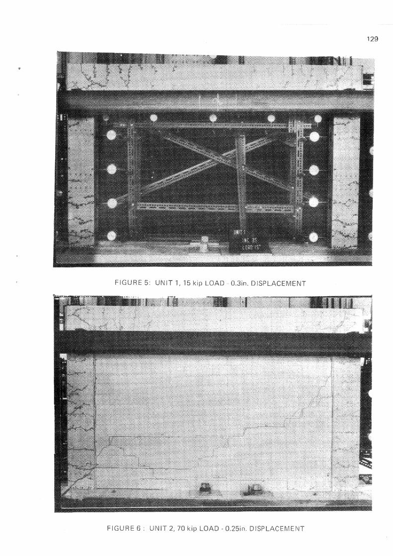
FIGURE 8 : UNIT 2, 70 kip LOAD - 0.25in. DISPLACEMENT

FIGURE 7: UNIT 2 4 8 k ip L O A D - 0 . 3 i n . D I S P L A C E M E N T
F I G U R E 8 : L O A D D E F L E C T I O N C U R V E - F R A M E & UNRE1NFORCED PANEL - U N I T 2

FIGURE 10 : UNIT 3, 58 kip LOAD ~ 1.8in, DISPLACEMENT