masks for hadamard transform optics, and weighing …neilsloane.com/doc/me47.pdfmasks for hadamard...
TRANSCRIPT

Masks for Hadamard transform optics,and weighing designs
Neil J. A. Sloane and Martin Harwit
This paper gives a brief survey of the design of masks for Hadamard spectrometers and image scanners.Three different criteria are described for judging a mask, as well as techniques for choosing masks that arenot too far from the optimum.
1. IntroductionThe use of masks to improve the performance of
spectrometers and image scanners has been proposedby a number of authors,1-8 and several papers existdescribing experiments performed with such instru-ments.8 -'2
Briefly, such an instrument consists of four essen-tial components: an optical separator, an encodingmask, a detector, and a processor (Fig. 1).
The separator might be nothing more than a lensthat produces a focused image at the mask, therebyseparating light arriving from different spatial ele-ments of a scene. It might equally well be a dispers-ing system that separates different spectral compo-nents of a beam and focuses them onto different loca-tions on the mask.
A particular location on the mask either transmitslight to the detector, absorbs the light, or reflects ittoward a reference detector. In this way, the intensi-ty of an element of the separated beam is modulated;its intensity is, respectively, multiplied by +1, 0, or-1, since the readings that are recorded are the dif-ferences in the intensity of light reaching the maindetector and reference detector.
If there is only one detector, the modulation con-sists of +1's and O's only, and the recorded intensityis just the intensity of radiation transmitted by themask.
When m intensity values are to be determined, atleast m different detector readings corresponding tom different mask arrays are required.
N. J. A. Sloane is with Bell Laboratories, Murray Hill, New Jer-sey 07974. M. Harwit is with Cornell University, Center for Ra-diophysics & Space Research, Ithaca, New York 14853.
Received 16 April 1975.
Three important questions in designing such an in-strument are: (a) How should the mask be chosen?(b) How much does this improve the accuracy of themeasurements? (c) How close is this to the optimummask design?
Such questions have been studied for many yearsin statistics under the name of weighting designs.Up to now this seems to have escaped the notice ofworkers in optics, but a considerable body of litera-ture exists (see, for example, Raghavaraol3 or Baner-jee'4).
Even so, the specific answers to (a), (b), and (c) arenot readily available in this literature, and so we shallgive here a short survey of what is presently knownabout the answers. The expert in statistics will findlittle that is new; however, we do give the first com-plete proof we have seen that the average meansquare error for the best mask of O's and l's is aboutfour times that for the best mask of -l's, O's, and+1's.II. Weighing Designs and Masks
Yates'5 seems to have been the first to point outthat by weighing several objects together instead ofseparately it may be possible to determine the indi-vidual weights more accurately.
For example, suppose four objects are to beweighed, using a balance that makes an error e eachtime it is used. Assume that e is a random variablewith mean zero and variance a2.
First, suppose the objects are weighed separately.If the unknown weights are xi, X2, X3, X4, the mea-surements are Yi, YZ Y, 4, and the errors made bythe balance are el, e2, e3, e4, the four weighings givefour equations:Yl = xi + el, 2 = x2 + e2 , y3 =x3 + e3,
Y4= X4 + e4.
The best estimates of the unknown weights are themeasurements themselves:
January 1976 / Vol. 15, No. 1 / APPLIED OPTICS 107

Reference L..._._ _.__.Detector … -l
I__ _ _ I
1 1
Incident pt ic: - I---Bem Separator E ~ re..r
MaskFig. 1. The prime components used in Hadamard transform
optics.
Xl= y = X + el, X2 = Y2 = X2 + e2 .
These are unbiased estimates:Exl = x, Ex2 = x2, . . . (E denotes expected value),
with variance or mean square error
E(i - )2 = Ee 2 = 2,.
On the other hand, suppose the balance is a chemi-cal balance with two pans, and the four weighings aremade as follows:
Y = X + X2 + X3 + X4 + el,Y2 = x - X2 + X3 - X4 + e2, (1)Y3 = X + X2 - - X4 + e3 ,Y4 = X - X2- X3 + X4 + e 4 .
This means that in the first weighing all four objectsare placed in the left-hand pan, and in the otherweighings two objects are in the left pan and two inthe right. Since the coefficient matrix on the right isa Hadamard matrix, it is easy to solve for X1, X2, X3,X4. Thus the best estimate for x1 (see below for ajustification of this) is
l= ( + Y2 + 3 + 4)= + (el + e2 + e3 + e4).
The variance of ce, where c is a constant, is c2 timesthe variance of e, and the variance of a sum of inde-pendent random variables is the sum of the individu-al variances. Therefore the variance of x1i (and alsoof X 2, X3, X4) is 4 a2/16 = 2 /4.
Weighing the objects together has reduced themean square error by a factor of 4.
Finally, suppose the balance is a spring balancewith only one pan, so only coefficients 0 and 1 can beused. A good method of weighing the four objects is
Yl = x 2
Y2 = x + 2Y3 = XiY4 = Xi
+ X3 + X4 + el,+ e 2,
+ X3 + e 2,+ X4 + e 4 -
In this case the variances of x1, X2, X3, X4 are 4o-2/9,7o.2/9 7 2 /9, 72/9, respectively, a smaller improve-ment than in the previous case.
In general, if there are p unknowns x, ... , xp, and
N measurements yl, . . , YN are made, involving er-rors el, . . , eN, we have
Yi = WijX1 + . . . + wipx + e, i = 1, . . ., N,
or in matrix formy = Wx + e, (3)
where y = (Y,, . . , YN), x = (xi, * * , xp)T, e = (el,... eN)T, and T denotes transpose. A particularchoice for the NXp coefficient matrix W = (wij) iscalled a weighing design.
The connection with Hadamard transform optics isstraightforward. In this type of optical system thexi's represent individual spatial and/or spectral ele-ments whose intensities are to be determined. Incontrast to scanning instruments that would measurethe intensities one at a time, the Hadamard trans-form optical system measures (i.e., weighs) the inten-sities of several xi 's simultaneously.
The two types of weighing design-the chemicalbalance design (with coefficients wil that may be -1,0, or +1) and the spring balance design (in which thecoefficients must be 0 or 1)-are realized in opticalsystems by masks W that use reflected, absorbed, ortransmitted light in the first case or simply open orclosed slots in the second case.4 In spite of the nameHadamard transform optics, the example of Eq. (2)shows that the matrices W should not be restricted tothose obtained from Hadamard matrices. (We shallrefer to W indiscriminantly as a mask, matrix, orweighing design.)
Weighing designs are also applicable to other prob-lems of measurements (such as lengths, voltages, re-sistances, concentrations of chemicals, etc.) in whichthe measure of several objects is the sum (or a linearcombination) of the individual measurements.14"16
In Secs. III and IV we shall discuss the best choicefor a weighing design, subject to the following as-sumptions:
(1) The errors ei are uncorrelated (see Banerjee17for the general case);
(2) The errors e are independent of the amountbeing weighed. In the weighing problem this as-sumes that the objects are light, and in the opticalscheme this is an assumption of linear behavior of thephotodetector. (Raghavarao et al.' 8 discuss a moregeneral case.)
(3) The number of measurements (N) is equal tothe number of unknowns (p), and the matrix W is in-vertible. Then the best (linear, unbiased) estimatefor x from Eq. (3) is4,19
= W'y - x + Wle.
(In the general case, when W does not have an in-verse, the best estimate is
= Why,
where W+ is the Moore-Penrose generalized inverseof W.20,21 If the rank of W is less than p, this iscalled a singular weighing design and may occur, for
108 APPLIED OPTICS / Vol. 15, No. 1 / January 1976

example, if an experiment is interrupted; e.g., sup-pose that a Hadamard transform spectrometer isused for an astronomical observation. Just beforethe end of the planned run of N measurements apatch of cloud passes over the dome. What informa-tion can be salvaged from the measurements actuallymade? Such questions are discussed by Raghavar-ao22 and Banerjee.2 3 )
Finally we mention that Kiefer,24 Kiefer and Wol-fowitz,25 and Fedorov'9 study more general problemsof the optimum design of experiments, including theuse of randomized weighing designs.
Ill. Matrices with Entries -1, 0, +1From now on we assume that (1), (2), (3) hold.
Then how should one choose the matrix, or mask,W? The mean square error of the estimate of the ithunknown xi is
i E - X) 2.
Ideally one would like to minimize simultaneously E,.. eN. The most important result is due to Hotell-ing,2 6 who showed that for any choice of mask Wwith Iwijl S 1, the E are bounded by ei ( 2/N), andthat it is possible to have Ei = (a 2 /N) for all i = 1,.. ., N if and only if a Hadamard matrix HN of orderN exists (by taking W = HN).
So if a Hadamard matrix of order N exists, takingW = HN gives the best possible weighing design.This design reduces the mean square error by a factorof N compared to the mean square error (a 2) of a sin-gle weighing. This result to some extent justifies thename Hadamard transform spectroscopy. Equation(1) was constructed with W = H4.
We note that the intensity values to be determinedcan correspond to any set of spatial elements.Whether these elements are arrayed in a linear dis-play such as in grating spectrometry, dr in a two-di-mensional array, as in imaging, is unimportant. TheHadamard matrix provides optimum encoding nomatter what shape the array may be.
A Hadamard matrix of order N is an N X N matrixHN of +1's and -1's that satisfies
HNHNT = NIN, IN = N X N unit matrix.
These matrices are thought to exist if and only if N =1, 2, or a multiple of 4. Numerous constructions areknown, and a plentiful supply of Hadamard matricesare available.27-30 So if N is a multiple of 4 andmasks with entries h1 can 'be used, the problem ofthe best choice of mask is solved.
What if N is not' a multiple of 4, or if only masks of0's and 1's can be used? Then it is not possible to si-multaneously minimize El, ... , EN, and some othercriterion must be used. Three different measure-ments of efficiency have been proposed:
An A-optimal 3 ' weighing design is one that mini-mizes the average mean square error, i.e., minimizes
= I (E + . . EN) = 4 Tr(WTW)l,
where Tr denotes the trace of a matrix.
A D -optimal3 2 design is one that maximizes themagnitude of the determinant of W I det(W)I. Thisis equivalent to minimizing the generalized varianceof the errors i - xi, which is 2 det(WTW)-l. A D-optimal design minimizes the volume of the region inwhich the estimate x is expected to lie.
An E-optimal33 design is one that maximizes thesmallest eigenvalue Xmin of WTW. To justify this,suppose one needed to determine a linear combina-tion of the xi's, say = clx+ . . . ± cNxN, where c12+... +cN 2 = 1. An E-optimal design minimizes themaximum mean square error of the best estimate 0for all choices of the ci's.
These criteria do not always agree. Probably A-optimality is the most important, provided the indi-vidual ei's are roughly equal.
It is reassuring that a Hadamard design W = HN isA-, D-, and E-optimal. In fact if W = HN, we have
cr2W = HN: = i =- detHj = NN",and Xmin = N, (4)
while for any other W we have
> N. IdetWI < N 2 , and Xmin < N.
The rest of this section describes masks that can beused when N is not a multiple of 4.
A. Masks from Conference MatricesThese are similar to Hadamard matrices but with a
slightly different defining equation. They also giverise to good weighing designs. A conference matrixCN of order N is an N X N matrix with diagonalentries 0 and other entries +1 or -1, which satisfies
CNCN = (N - 1)IN.
The name arises from the use of such matrices in thedesign of networks having the same attenuation be-tween every pair of terminals (see Belevitch34-36).
N must be even for CN to exist. But if N is a mul-tiple of 4 these are inferior to Hadamard matrices, sowe shall assume N has the form 4t + 2. In this case,by suitably multiplying rows and columns by -1, CNcan be put in the form
-0 1 1.. .1-
CN = I BN-I
_i
where BN-1 = (bij) is a symmetric matrix.37 Severalconstructions for conference matrices areknown.29 30 37 38 The most useful for our purpose isPaley's construction39: Let N = 4t + 2 = p + 1,where p is an odd prime, and set bij = 0 if i = j, bij =1 if j - i is a square (modulo p), and bij = -1 ifj - iis not a square (modulo p). The resulting matrix (5)is a conference matrix. For example, if p = 5, thesquares modulo 5 are 12 = 1,22 = 4, and we obtain
January 1976 / Vol. 15, No. 1 / APPLIED OPTICS 109
(5)
0 1 1 1 1 11 0 1 - - 1
C6 = 1 1 0 1 - -, where - stands for-1.1- 1 0 1-1 - -I 0 1
11--~~I 0
Note that this 'construction gives a matrix BN-1 thatis a circulant.
The same construction works if p is replaced byany odd prime power pm-; the rows and columns ofBN-1 are labeled with the elements of the Galois fieldGF(pm); b = 1 if j- 1 is a square in GF(pm); etc.Now BN-1 is not a circulant. Galois fields are finitefields (see, e.g., Raghavarao1 3 ).
The construction gives symmetric, circulant, con-ference matrices of orders 6, 14, 18, 30, 38, 42, 54, 62,... , and symmetric conference matrices of orders 10,26, 50, .... The matrices Cio, C14, C18 are given infull by Raghavarao. 4 0
Choosing the mask W = CN we obtain a weighingdesign40 that has the parameters
W = CN: = =- N 1' IdetCNI = (N -
Arni, = N- 1. (6)
These are only slightly inferior to the parameters of aHadamard matrix, Eq. (4). We mention in passingthat for N = 4t + 1 the mask W = BN + IN has e = i= (2a 2 )/(N - 1).
B. Masks from Symmetric Block DesignsAn (N, k, A) symmetric block design consists of a
collection of subsets (called blocks) of size k takenfrom a set of N objects, such that any two blockshave exactly X objects in common. [N, k, and X arerelated by k(k - 1) = A(N - 1).]
For example, the blocks of a (7,3,1) design are124, 235, 346, 457, 561, 672, 713.
From one symmetric block design we can alwaysget another by taking as blocks the complements ofthe original blocks, that is, the objects not in the orig-inal blocks. This is an (N, k' = N -k, X' = N-2k+ A) symmetric design. The complement of the pre-ceding example is a (7,4,2) design with blocks
3567, 4671, 5712, 6123, 7234, 1345, 2456.
Block designs are frequently used in statistics, andmany methods of construction are available.41 (Thestatistical literature uses v instead of N for the num-ber of objects.)
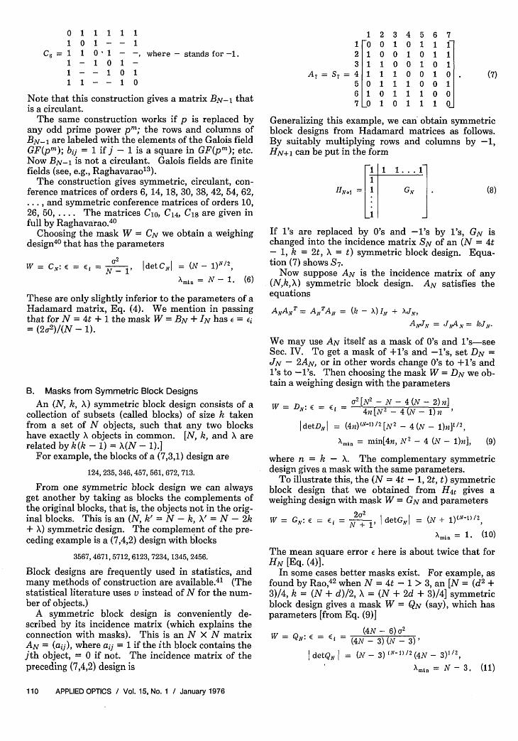
A symmetric block design is conveniently de-scribed by its incidence matrix (which explains theconnection with masks). This is an N X N matrixAN = (aij), where aij = 1 if the ith block contains thejth object, = 0 if not. The incidence matrix of thepreceding (7,4,2) design is
121 F0 02 1 03 1 1
A 7 = S7 = 4 1 15 0 16 1 07 _o1
345 67101 11]010 11001 01100 10.110 01111 00011 10Generalizing this example, we can' obtain symmetricblock designs from Hadamard matrices as follows.By suitably multiplying rows and columns by -1,HN+ 1 can be put in the form
HN.1 =
If 's are replaced by 0's and -'s by 's, GN ischanged into the incidence matrix SN of an (N = 4t- 1, k = 2t, X = t) symmetric block design. Equa-tion (7) shows S7 .
Now suppose AN is the incidence matrix of any(N,k,X) symmetric block design. AN satisfies theequationsANAN = ANTAN = (k - X) IN + JN,
ANJN = JAN = kJN-
We may use AN itself as a mask of 0's and 1's-seeSec. IV. To get a mask of +1's and -'s, set DN =JN - 2AN, or in other words change 0's to +1's andI's to -'s. Then choosing the mask W = DN we ob-tain a weighing design with the parameters
W = DN: E = (i = '[N2- N - 4 (N - 2)n]4n[N2 -4(N-I )n
IdetD, = (4n)(N-D/2 [N2 - 4(N - )n]l/2,Xm = min[4n, N 2 - 4 (N - )n], (9)
where n = k- A. The complementary symmetricdesign gives a mask with the same parameters.
To illustrate this, the (N = 4t - 1, 2t, t) symmetricblock design that we obtained from H4t gives aweighing design with mask W = GN and parameters
W = G: E = Ei = N + detGN1 rMin = 1. (10)
The mean square error E here is about twice that forHN [Eq. (4)].
In some cases better masks exist. For example, asfound by Rao,42 when N = 4t-1 > 3, an [N = (d2 ±3)/4, k = (N + d)/2, X = (N + 2d + 3)/4] symmetricblock design gives a mask W = QN (say), which hasparameters [from Eq. (9)]
W =QN:E= E (4N- 6) 2(4N -3) (N -3)'
detQf = (N- 3)(N- )/2(4N- 3)1/2Amin = N - 3. (1)
110 APPLIED OPTICS / Vol. 15, No. 1 / January 1976
(7)
(8)

These parameters are better than Eq. (10). Unfortu-nately, at present the only known designs of this fam-ily are Q7 and Q31. This is typical: the best sym-metric block designs for our purposes have k roughlyequal to /2N and give masks with very good parame-ters, but not many examples are known.
A similar situation holds for N = 4t + 1. In thiscase as Raghavarao 4 0 has shown, an [N = (d2 + 1)/2,k = (N + d)/2, X = (N + 2d + 1)/4] symmetric blockdesign gives a mask W = PN (say), which has param-eters
W = Pn E. = i = 2N - '| detP| = (N - 1)(Nl) 2(2N - 1)1/2, Xmin = N - 1. (12)
WN = [T ] = EN (say), (17)
where X and Y are (N/2) X (N/2) circulant matriceschosen so that
EN TEN = [ ], Z = (I2 N 2)N/2 + 2JN2-
The parameters of this weighing design are
WN = EN: E = i= N- | detEN I = 2(N - 2) (N-2)/2 (N - 1), mi = N - 2. (18)
Again, at present only P5, P13, and P25 are known toexist. The corresponding matrices are given in Ref.40.
C. Masks with WWT = al + OJAll the masks given so far [except for Eq. (2)] have
the property that the mean square errors of the un-knowns, the E's, are equal. In much statistical liter-ature it is assumed that the weighing design satisfiesthe conditions
Ei = E(x - i) 2 = E (independent of i)and (13)
E(i- xi) (j - x) = 1 (independent of ij, for i j).
This is equivalent to assuming that WN satisfiesWNWNT = aIN + flJN for suitable a and 3. Withthese assumptions, Raghavaro1340 has shown that PNis A-, D-, and E-optimal, that CN is A- and E-opti-mal, and Rao42 has shown that QN is A- and E-opti-mal for N > 3.
However, as the weighing designs (2), (17), and(20) show, weighing designs that do not satisfy Eq.(13) may have a lower average mean square error, ora larger determinant or Amin, than those that do.
D. Masks with the Largest DeterminantLet us consider the problem of finding a D-optimal
mask WN, that is, an N X N matrix of -1's, 0's, and+1's with the largest possible determinant. Let g(N)denote this largest determinant. By expanding thedeterminant about any column, it follows that thelargest determinant can always be attained by a ma-trix containing only -1's and +1's (and no zero's).
The following bounds on g(N) are known43:
( NN/2 if N = 4t; (14)g(N) (N - )(N-1)/2 (2N - 1)1/2 if N is odd; (15)
( 2(N - 2 ) (N-2)/2 (N- 1) if N = 4t + 2. (16)
We have already seen [Eq. (4)] that if N = 4twe can achieve g(N) = NN/2 by a Hadamardmatrix. For many values of N = 4t + 2,g(N) = 2(N - 2)(N-2)/2(N - 1) can be achieved bydouble circulant matrices of the form
For example, a D-optimal mask with N = 6 is
11 11 1
1 1 1E6 =-
- 1 -.- -
-1 11- 111 -11 111 11 1 1_
(19)
Ehlich4 4 and Yang4 5' 46 have given such matrices forN = 2, 6, 10, 14, 18, 26, 30, 38, 42, 46, 50, 54, 62, 66.It is interesting to compare Eqs. (18) with the param-eters (6) of the CN matrices. They both appear toexist for the same values of N. EN has the samemean square error, slightly larger determinant (largerby a factor of about 1.21 when N is large), but smallerXmin-
The matrices P5 , P13 , P2 5 achieve Eq. (15) and soare also D-optimal. The exact value of g(N) isknown4 7 for N < 14.
For large N, a good method of obtaining a matrixwith a large determinant is to take the next largestHadamard matrix and prune it to size.48
E. Small MasksTo end this section we give three matrices found
by Mood,16 which show that the best weighing de-signs can be complicated, even for small N, and neednot satisfy Eqs. (13). For N = 3, there are three ma-trices with the largest determinant, 4, namely:
(20)
The corresponding parameters are(E1, E2 , E3 )/&2
(a) ( 2' 3 3
(c) ( 2 2 2
E/U2
512
1
det Xmin
4 2;
4 1;
4 1.
Mood also gives D-optimal designs for N = 5, 6, and7.
January 1976 / Vol. 15, No. 1 / APPLIED OPTICS 111
I
I 1 1 ) I(b) G , -2, _2 2
0 1 1 1 1 1 1(a) I - I ; (b) I - ; (C) - I .
I I - I I I -

IV. Matrices with Entries 0 and 1A matrix (or mask) W with entries 0 and 1 is usual-
ly less expensive to build than a mask with entries-1, 0, and +1. However, the price that must be paidfor this is an increase by a factor of about 4 in themean square error . This result is derived in theAppendix and can be observed by comparing the de-signs of this section with those of Sec. III.
If WN+1 is an (N + 1) X (N + 1) matrix withentries -1 and +1 only, there is a standard way to getan N X N matrix XN of 0's and 's. By suitablymultiplying rows and columns of WN+1 by -1, makethe first row and column equal to +1. Then deletingthis first row and column and changing +1's to 0'sand -1's to 's we obtain XN. For example,
W3= [ 1 givesX2 = [o I]
The determinants of WN+1 and XN are related bydetWNi = ( -2)NdetXN. (21)
A. Masks with the Largest DeterminantBecause of this transformation from WN+1 to XN,
the problem of finding the largest determinant of anyN X N matrix of 0's and 's is equivalent to the prob-lem of finding the largest determinant of any (N + 1)X (N + 1) matrix of -1's and +1's. A solution to oneproblem gives a solution to the other.49 If f(N) de-notes the value of the largest (0,1) determinant, Eq.(21) implies
f(N) = (1/2N)g(N + 1).
Therefore all the results about g(N) given in Sec. IIIapply to f (N). In particular,5 2 N(N)(N + 1)/2 if N = 4t - 1, (22)
f(N) ' 2-NNN 2 (2N + 1)1/2 if N is even, (23)(2-+'N(N - 1 )(N-)/ 2 if N - 4t + 1. (24)
The matrices EN+1 of Eq. (17) produce D-optimal(0,1) matrices EN (say) for N = 4t + 1, with
I detEr I = 2-N+IN(N - 1) (N-1) /2 (25)
W = SN:E Ej = 4Nuy2W = N: = (N + 1)2
detS,1 = 2N(N + 1 )(NI1)/2 xi = - (N + 1), (26)
and is D-optimal (and presumably also A- and E-optimal 5 0 ).
C. Masks from Symmetric Block Designs5 1 - 54
Now we may use the incidence matrix AN itself asthe mask. This has the parameters
W = AN: ( = = k(N - 2) + 1 2E = E k2 (N - ) I detAN| = k(k- X) (N-)/2; min = k - X. (27)
Example55: For N = 13 there are three symmetricblock designs, all with circulant incidence matrices.The parameters of the corresponding masks are asfollows:
(N, k, ) 1st row of AN E/U2 E/&2 Amin(a) (13,4,1) 1101000001000 0.314 2916 3(b) (13,9,6) 1111101110010 0.309 6561 3(c) (13,12,11) 1111111111110 0.924 12 1.
Note that (a) and (b) are complementary symmetricblock designs. Thus in the (0,1) case complementingcan change the parameters. Design (b) is clearly thebest of the three, although it has a smaller determi-nant than the D-optimal design E13, which has deter-minant 9477.
D. Small MasksFinally, we give the two D-optimal (0,1) matrices
for N = 4 (Mood16):
0o 1
(a) 1 1
1 1
1 1- 1
0 1 I (b) 11 0j L1
11 11 0 0
1 o I
Matrix (b) was used in Eq. (2). The correspondingparameters are
(There seems to be no simple formula for or Xmin.)For example,
o oE = I 1
1 oLo I
1 0 11 0 0 .O 1 1O 1 1_1
B. Masks from Hadamard MatricesSimilarly a Hadamard matrix HN+1 produces the
(0,1) matrix SN, where N = 4t - 1, as in the para-graph following Eq. (8). This weighing design hasthe parameters
E/U2 det X in
0.778 3 3,
0.694 3 1.56.
E. Summary
Table I gives a summary of these results, giving thename of the mask W and the equation where its pa-rameters can be found. These parameters are theaverage mean square error (the most important),the determinant of the mask, and the smallest eigen-value Xmin of WTW. The standards by which tojudge these parameters are those of the Hadamardmask [Eq. (4)]. For masks of -'s, 0's, and +1's,Hadamard masks HN are the best, while the binary
112 APPLIED OPTICS / Vol. 15, No. 1 / January 1976
(E I E2 IE3,E4) /U2
(a) 7 7 7 7 ( 9, -9, -9,
(b) 4 I 7I 7 I 7 ( 9 9 9

Table I. Summary of Masks, Giving Name, Size (N X N), Equation whereParameters can be Found, and Values of N for which Defined
N = 4t N- 4t + 1 N = 4t + 2 N = 4t + 3Masks of HN,Eq(4): DN,Eq(9): all N CN,Eq(6): many N DN,Eq(9): all N-1's,0's,+1's all N(?) BN + IN: many N EN,Eq(l 8): many N GN,Eq(10): all N(?)
PN,Eq(12): N = 5,13,25 QNEq(11): N = 7,31
Masks of AN,Eq(27): EPEq(25): many N AN,Eq(27): all N SN,Eq(26): all N(?)0's,1's all N
Hadamard masks SN are the bestl's.
masks of 0's and
V. DiscussionIn Sec. II we briefly mentioned singular designs.
To date users of Hadamard optics have not made useof instruments operating in this mode, but a wholenew area of optical development may open up in thisdirection.
Suppose that the image of a scene is to be obtainedin the presence of natural or deliberate interferencethat comes in the form of noise spikes that make in-dividual intensity measurements completely useless.These measurements can be clearly identified be-cause they are much larger (noisier) than expectedand can therefore be eliminated; but the informationthey were meant to gather is lost.
If we operated in a normal scanning mode in whichwe studied the scene element by element, we wouldirretrievably lose all information about some ele-ments. But the use of Hadamard optics can permiterror corrections so that information about each pic-torial element is obtained despite the noise.
We can, for example, make use of an N X p encod-ing mask with N rows to encode a scene with p = N- n elements, where n' is the number of measure-ments expected to be compromised through noise.The n noisy measurements can then be removed, andthe brightness distribution of the p picture elementscalculated on the basis of the p relatively noisefreedata points.
This type of procedure of course is reminiscent of,and makes available to optics, much of the body ofknowledge that constitutes coding theory-the studyof the transmission of messages through a noisy me-dium. This is effectively done by adding redundan-cy to the message in such a way as to permit errorcorrection. In the same way, the redundancy builtinto the Hadamard mask in the example given abovewould be used for error correction. This entire topicis too large to treat here in detail, but it provides anatural future for Hadamard transform optics.
Similar considerations can also enter the design ofan optical system in which the number of unknownsto be determined p does not correspond to the rankof any Hadamard matrix. In that case the optimumprocedure may be the construction of a system thatcould in principle solve for N unknowns, N > p,where N is the rank of a known Hadamard matrix.
Thanks are due to L. A. Shepp for suggesting theuse of the arithmetic-mean geometric-mean inequali-ty in the Appendix and to C. L. Mallows for helpfuldiscussions. The work of the second author has beensupported by NASA grant NGR 33-010-210 andAFCRL contract F19628-74-C-0110.
AppendixTheorem: For any (0,1) matrix WN, the average
mean square error e - 4o-2/N as N -O
Proof: Let XI, ... , XN be the eigenvalues of(WNTWN)- 1. Then
E = N Tr(wNTwX1 = N
> u2 (Xi . . XN)IN by the arithmetic-mean geometric-mean inequality,
= c2(detWTW, )1/N - 2(detWN)-2/N- a24(N + 1 )-(N+1))/ by Eqs. (22), (23), (24)- 4/N as N - oo Q. E. D.
All previous proofs of this result seem to assume ei-ther that Eq. (13) holds, or else56 that there is oneobject that is present in every weighing, i.e., that thespring balance is biased.References1. F. Gottlieb, IEEE Trans. Info. Theory 14, 428 (1968).2. R. N. Ibbett, D. Aspinall, and J. F. Grainger, Appl. Opt. 7,
1089 (1968).3. J. A. Detker, Jr., and M. 0. Harwit, Appl. Opt. 7, 2205 (1968).4. N. J. A. Sloane, T. Fine, P. G. Phillips, and M. Harwit, Appl.
Opt. 8, 2130 (1969).5. M. Harwit, P. G. Phillips, T. Fine, and N. J. A. Sloane, Appl.
Opt. 9, 1149 (1970).6. J. A. Decker, Jr., Appl. Opt. 9, 1392 (1970).7. E. D. Nelson and M. L. Fredman, J. Opt. Soc. Am. 60, 1664
(1970).8. M. Harwit, Appl. Opt. 10, 1415 (1971) and 12, 285 (1973).9. J. A. Decker, Jr., Appl. Opt. 10, 510 (1971).
10. P. G. Phillips and M. Harwit, Appl. Opt. 10, 2780 (1971).11. P. G. Phillips and D. A. Briotta, Jr., Appl. Opt. 13, 2233 (1974).12. M. Harwit, P. G. Phillips, L. W. King, and D. A. Briotta, Jr.,
Appl. Opt. 13, 2669 (1974).13. D. Raghavarao, Constructions and Combinatorial Problems in
Design of Experiments (Wiley, New York, 1971), Chap. 17 andAppendix A.
14. K. S. Banerjee, Weighing Designs for Use in Chemistry, Medi-cine, Economics, Operations Research and Statistics (Dekker,New York, 1975).
January 1976 / Vol. 15, No. 1 / APPLIED OPTICS 113

15. F. Yates, J. R. Stat. Soc. Suppl. 2, 181 (1935) (see p. 211).16. A. M. Mood, Ann. Math. Stat. 17, 432 (1946).17. K. S. Banerjee, Ann. Math. Stat. 36, 1829 (1965).18. D. Raghavarao, J. S. Sodhi, and R. singh, Calcutta Stat. Assoc.
Bull. 20, 83 (1971).19. V. V. Federov, Theory of Optimal Experiments (Academic,
New York, 1972).20. R. Penrose, Proc. Cambridge Philos. Soc. 51, 406 (1955); 52, 17
(1956) [see also A. Albert Regression and the Moore-PenrosePseudoinverse (Academic, New York, 1972)].
21. C. M. Price, SIAM Rev. 6, 115 (1964).22. Ref. 13, p. 321.23. K. S. Banerjee, Ann. Math. Stat. 37, 1021 (1966); 40, 719
(1969); J. Am. Stat. Assoc. 67, 211 (1972); P. K. Hazra and K.S. Banerjee, J. Am. Stat. Assoc. 68, 392 (1973).
24. J. Kiefer, Ann. Math. Stat. 29, 675 (1958) and J. R. Stat. Soc.,Ser. B. 21, 272 (1959).
25. J. Kiefer and J. Wolfowitz, Ann. Math. Stat. 30, 271 (1959).26. H. Hotelling, Ann Math. Stat. 15, 297 (1944); rediscovered by
Nelson and Fredman. 7
27. L. D. Baumert, in Digital Communications with Space Appli-cations, S. W. Golomb, Ed. (Prentice-Hall, Englewood Cliffs,N.J., 1964), pp. 47-64.
28. M. Hall, Jr., Combinatorial Theory (Blaisdell, Waltham,Mass., 1967), Chap. 14.
29. W. D. Wallis, A. P. Street, and J. S. Wallis, Combinatorics:Room Squares, Sum Free Sets, Hadamard Matrices, LectureNotes in Math. 292 (Springer Verlag, New York, 1972), Part 4.
30. J. H. van Lint, Combinatorial Theory Seminar, EindhovenUniversity of Technology, Lecture Notes in Math. 382(Springer Verlag, New York, 1974), Chap. 14.
31. See K. Kishen, Ann. Math. Stat. 16, 294 (1945) and Ref. 13, p.315.
32. See Mood' 6 and Ref. 13, p. 315.33. See S. Ehrenfeld, Ann. Math. Stat. 26, 247 (1955) and Ref. 13,
p. 315.34. V. Belevitch, Elect. Commun. 27, 231 (1950).
35. V. Belevitch, in Proc. Symp. Modern Network Synthesis (Po-lytech. Inst. Brooklyn, New York, 1956), pp. 175-195.
36. V. Belevitch, Ann. Soc. Sci. Bruxelles 82 (I), 13 (1968).37. P. Delsarte, J. M. Goethals, and J. J. Seidel, Can. J. Math 23,
816 (1971).38. J. M. Goethals and J. J. Seidel, Can. J. Math 19, 1001 (1967).39. R.E.A.C. Paley, J. Math Phys. 12, 311 (1933).40. D. Raghavarao, Ann. Math. Stat. 30, 295 (1959); 31, 878 (1960).41. See, for example, Ref. 13, Chap. 5; Ref. 28, Chaps. 10, 15, and
Table I; Ref. 30, Chaps. 10, 15.42. M. B. Rao, Ann. Math. Stat. 37, 1371 (1966).43. J. Brenner and L. Cummings, Am. Math. Mon. 79, 626 (1972).44. H. Ehlich, Math. Z. 83, 123 (1964).45. C. H. Yang, Math. Comp. 20, 147 (1966); 22, 174 (1968); 23, 201
(1969).46. C. H. Yang, "Maximal Binary Matrices and Sum of Two
Squares," submitted to Math. Comp.47. H. Ehlich and K. Zeller, Z. Angew. Math. Mech. 42, 20 (1962).48. G. F. Clements and B. Lindstr6m, Proc. Am. Math. Soc. 16,
548 (1965), show that in this way one can always obtain matri-ces of -l's and +1's with determinant at least N(N/2)[1 - log(4/3)/logN].
49. See, for example, J. H. E. Cohn, Proc. Am. Math. Soc. 14, 581(1963).
50. Although this seems not to have been proved. The theorem inthe Appendix shows that if N is large, SN is close to A-opti-
51.52.53.54.55.
mal.K. S. Banerjee, Ann. Math. Stat. 19, 394 (1948).K. S. Banerjee, Biometrika 37, 50 (1950).K. S. Banerjee, Calcutta Stat. Assoc. Bull. 4, 36 (1952).Ref. 13, p. 319.This example is discussed by Raghavarao, Ref. 13, p. 321.However, he incorrectly asserts that (c) is A-optimal. Thesymmetric block design (a) can be found, for example, on p.291 of Ref. 28.
56. S. Moriguti, Rep. Stat. Appl. Res. 3, 75 (1954).
Request for Information:Dedicated Synchrotron Radiation Source
NSF and ERDA are seeking to identify partiesinterested in a dedicated source of synchrotronradiation and capable of designing and constructingsuch a facility. The facility would be designed for theoptimum production of synchrotron radiation as anintense source of X-rays with wavelengths at 1 A orless, as well as the longer wavelength regions of theelectromagnetic spectrum.
This request is not for proposals but for preliminaryinformation to be used for defining the scope andformat of the project. Such information shouldinclude design concepts together with cost estimatesfor the basic synchrotron radiation source, auxiliaryinstrumentation, and support facilities includingbuildings. For additional information, contact HowardEtzel or W. T. Oosterhuis of the Division of MaterialsResearch, NSF, 1800 G St., N.W., Wash., D.C. 20550(632-7334), or Mark C. Wittels, Division of PhysicalResearch, ERDA, Wash., D.C. 20545 (301-973-3427).
114 APPLIED OPTICS / Vol. 15, No. 1 / January 1976