mask-bot 2i': an active customisable robotic head with ... · people's identication of...
TRANSCRIPT

“Mask-Bot 2i”: An active customisable RoboticHead with Interchangeable FaceBrennand Pierce, Takaaki Kuratate, Christian Vogl and Gordon Cheng
Institute for Cognitive Systems (http://www.ics.ei.tum.de), Technische Universitat Munchen
Abstract—This paper describes the development of “Mask-Bot 2i” (codenamed: Kabuto), a robotic head designed forresearch into Human-Robot-Interactions. The uniqueness of ournew robotic head is that the appearance of its face can be alteron-the-fly. Different faces can be projected onto the active headsystem. The head is fully active with a 3-DOF neck, with supportfor biannual hearing as well as video camera for seeing. Aninterchangeable face is the main feature of this new Mask-Bot,the head can be equipped with an average face mask as wellas a highly customised individualised face that can be easilyexchanged. Additionally, the actuation of the head has beendesigned to match the natural head movements of an averagehuman. Thus, enabling the head and face to be articulatedsynchronously to the speech production while the natural headmovement matches that of the animated face. The design andrealisation of this new system is presented in details in thispaper.
I. INTRODUCTION
During the last decades numerous humanoid robotic sys-tems have come to be. One element that is consistent amongthem all is the fact they are all equipped with a head. Asfrom the practical point of view, it is the most logical place tomount the visual and the auditory systems. But one might saythat it is also an important part of human-robot interaction(HRI), especially for face-to-face communication, as the headprovides a natural means of human interaction with a robot.This leads to the question, “what elements are important inthe design of a robotic head for HRI?”. For instance, wehave studied how the quality of the projected image effectspeople’s identification of the avatar’s gender with the original“Mask-Bot” [1]. For interaction, the head should be able tocommunicate using auditory (verbal and non-verbal) as wellas visual communication. But what about its appearance? Toexplore this question, we developed a robotic head that canbe used to carry out research into how the appearance of ananimated face displayed onto a robotic head effects HRI.
When a robotic head is designed it normally has oneprimary goal. For example, it could be designed with theaim of being a stable platform for activated cameras. Goodexamples of this are the head of the “iCub” humanoid robot[2]; or Karlsruhe humanoid head [3]. Another aim is tolook as life-like as possible, where the texture of the skin,the mimicking of the muscles are most important. Hansonrobotics developed a very realistic head used in the “Albert”version of HUBO humanoid robot [4], which utilises a highnumber of servo motors that were designed to mimic humanmuscles and deform its rubbery skin. This means the head isable to display emotions as well as to articulate the mouth
Fig. 1. The new “Mask-Bot 2i” (codenamed: Kabuto).
when it speaks. Simpler heads compared to the Hanson’shead are also used for displaying emotions. An early exampleof this type of head is MIT’s KISMET robot [5], which wasdesigned to display emotional expressions and had a simplemouth. These latter two examples rely heavily on complexmechanical structures, which need a high number of motorsto be controlled in order to modify their facial expressions.
To overcome these problems, there is an emerging typeof humanoid heads with the concept of displaying an avatarinstead of relaying on a complicated mechanical mechanism.Examples of this would be the “LightHead” by Delaunay etal.[6], [7] and the “Curved Screen Face” from Hashimoto andcolleagues [8], as well as our own robotic head “Mask-Bot”[9], [10]. This type of robotic heads have the advantage thatthe face can be changed and animated fairly easily. Also thearticulation of the face does not rely on complex mechanicalcomponents. This means that the mouth can be animated andsynchronised with the vocal system and it can also displayemotions. But current research on the projected heads havemainly focused on the animated side and have neglectedthe complete modalities that a robotic head needs, for ex-ample the integration of stereo microphones for “hearing”,cameras to “see” the world and the full articulation of head
2012 12th IEEE-RAS International Conference on Humanoid RobotsNov.29-Dec.1, 2012. Business Innovation Center Osaka, Japan
978-1-4673-1369-8/12/$31.00 ©2012 IEEE 520

P a n A x i s
L E D P r o j e c t o r
F i s h - e y eL e n s
M o u n t b a s e
M a s kS c r e e n
T i l t C e n t e r
T i l t m o t o r
P a n m o t o r
C o n t r o l b o x
P a n - T i l t U n i t
Proj
ectio
nAr
ea
Fig. 2. 1st generation “Mask-Bot”
movements. To date, all the current projected heads have afixed, very simple surface to project their avatar. From ourexperience this has a down side as different avatars workbetter with different shaped masks.
In this paper, we present our new humanoid head with aprojected face, Mask-Bot 2i (see Fig. 1). This robotic headhas been developed as a standalone platform for performingresearch into human-robot interaction (HRI). In the nextsection, we present the system requirements that lead tothe specification for this robotic head. Section III and IVpresent the unique feature of our robotic head, which is itsinterchangeable projected face. In section V, VI and VII theimplementation of the complete system is discussed in detail.Finally, the results and the conclusion are presented in sectionVIII and IX.
II. SYSTEM REQUIREMENTS
To build our new head we took into account our experiencewith the original prototype Mask-Bot (see Fig. 2), which wasdesign and created to validate the feasibility of a projectedface for HRI. With Mask-Bot 2i we decided to pay moreattention to the complete system and not just focus on thedisplaying aspects of the avatar. We found a couple ofshort coming with the previous head: The overall systemwas noisy, which was distracting when using it for HRIexperiments. Also, the mask we used had too much surfacedetails in the eye and lip regions, which made it hard toalign with the avatar being projected. This mask was alsonot interchangeable, which means we were unable to carryout experiments into how different masks affect the avatarbeing projected. There was also no way for Mask-Bot to trulyinteract with its surroundings as it had no way to “see” orthe ability to know where the person, who it was interactingwith, was located. This lead to an unnatural HRI, as the robotwould not always be facing the person it was interacting with.This lead to the new requirements for a new robotic head:
• The robot head should have an interchangeable mask,so that we can experiment with different masks anddetermine how it effects the appearance of the avatarbeing projected.
• The robot head should model the major degrees offreedom (DOFs) of a human, so that there is adequatevelocity and range to replay human-like motion data in
Fig. 3. Test-rig. Built to test projector position coupled with differentfisheye lenses and mirror configurations.
a smooth and natural manner.• The overall size should be as close as possible to an
average adult human, so that the projected avatar canbe displayed at a natural size.
• It should provide a vision system, so that it can interactbetter with the human, for example tracking the face ofa person during interaction.
• It should have an audio system capable of 3D soundlocalisation, so that it can locate the person that it isinteracting with.
• It should be quiet, so that the sound of the head’shardware does not create a distraction during HRIexperiments.
Based on these system requirements, we derived our newfull system.
III. PROJECTOR SYSTEM
The main feature of this robotic head is the avatar animatedonto a mask using a projection system. There are threemain hardware components used to achieve this: 1) theprojector; 2) the optics used to modify the light beam; and 3)the mask. So when designing our new head this projectionsystem hardware dominated our design. Therefore, we hadtwo main design goals for the projector system comparedto the original. First we wanted to reduce its weight, thuswe could reduce the size of the actuators, which in turnwould reduce the noise. The second goal was to make theoverall projection system more compact so that it fits intothe footprint of an average adult human.
The most obvious and easiest way of making the projectionsystem smaller and more compact was to use a smallprojector. Through numerous trials, we selected the LEDprojector C112 (Acer Inc.), which is 70 ANSI lumens andhas a contrast ratio 1000:1. This has the advantage of being421% lighter then the original projector e.g., 138g comparedto 582g, but has the disadvantage of only having 35% thelumens. After experiments with this new projector we feltthat the trade off was worth it - as it can still provide adequatebrightness for the projection of the face. After the selectionof the projector we needed to design the optic system. In
521

TABLE ISYSTEM OVERVIEW; MOTOR, SENSORS AND COMPUTATIONAL SYSTEM.
Kinematics 3 DOF in the neck arranged as pan, tilt and roll.Actuators 5W brushless motor - “351008” by maxon.Gear Ratio Pan 1:200; Tilt 1:120; Roll 1:120.Encoders 14bits digital encoder - “Vert-X 13” by contelec.Vision Camera 1920 x 1080 @ 30Hz - “C920” by Logitec.Auditory Stereo microphones.Inertial Sensors 6 axis IMU, combined 3-axis gyroscope and 3-axis
accelerometer - “MPU-6000” by invensense.Control Module FPGA, running onboard PID at 5Khz - “Sparten 6
XL45” by Xilinx.MOSFET 3 x 5A integrated three phase motor driver, con-
trolled at 24.4Khz- “L6234” by STMicroelectronics.Communication Ethernet; UDP packets, running at 2Khz.Control PC Intel i7 PC, running Ubuntu Linux OS.Software Framework Robot Operating System (ROS)
the original Mask-Bot we used a fisheye lens which requiredto be aligned along the same plane as the projector. Thishad one major disadvantage as it required the projection tobe very far away from the mask, thus, making the overallsystem very long, with a large volume.
Therefore, for our new projection system we needed tovalidate different combinations of different lenses and mir-rors to determine the smallest volume we could achieve. Forthis purpose we created an experimental test-rig, as shown inFig. 3, which allows us to easily modify all the key variables,i.e. mirror, fisheye lens and alignment between components.We achieved this by building different adjustable arms withdifferent sizes and shapes. To test the result we projecteda grid pattern which made it possible to test the resultingimage with respect to the area covered and the focal of theresulting image.
After our empirical studies we determined that a fisheyelens by “pixeet”, designed for a mobile phone camera withan viewing angle of 180 degrees, the size 30mm x 17mm andweight 18g, gave the best results when size and weight weregiven the highest priority. The mirror, which was aligned thesame as in the configuration shown in Fig. 3, gave us thebest result in the smallest volume. The main problem wefaced with the alignment was the trade off between overallsize and covering the complete mask. Also, as the projectoris LCD based and the focus is designed for a flat screen,which means it was difficult to get the focus to be perfectfor the complete mask due to its complex 3D shape. Thus, wehad to make a compromise. We made sure that the two mostimportant features, the eyes and mouth, were in focus. Thatmeans the edge of the face and tip of the nose were slightlyout of focus, which both can be said to be less significantfor HRI.
IV. INTERCHANGEABLE MASK
In our previous prototype version of the Mask-Bot wesimply used a commercially available manikin head. In thisnew version it would be desirable to be able to experimentwith different shaped masks: from a very generic version,where we could project any avatar onto, all the way toa highly specific mask that matches the projected avatar
Fig. 4. Designing the interchangeable mask; a) Average face data; b) Thecleaned up dataset; c) the CAD model of the mask with the correct outershape to fit into the Mask-Bot frame; d) The 3D printed mold after beingsprayed in white paint then sanded back to give a smooth surface finish; e)The vacuum forming process; f) The final sprayed mask.
created from 3D scan data of a specific human subject. Thismeans that we needed to design the new head to have aninterchangeable function, which resulted in a frame designwhere different masks can be attached.
In order to produce a version of an interchangeable mask,we first developed a face-model which uses a mean averageof 124 faces (31 faces from each Caucasian male group,Caucasian female group, Asian male group and Asian femalegroup), with an age range of 18 to 50 years old and withthe average age of 29.4 years to create an “average” face(Fig. 4.a). Before we could use this data, it needed to bepreprocessed to reduce the noise and to trim the excess data(Fig. 4.b).
Next we imported this data into CAD software, so that wecan turn it into a solid object which can be manufactured.Afterwards, we applied a transformation function whichturned this data into a planner surface that can be modified.At the same time we applied a smoothing function to reducethe fine details like in the lip and eye area. Due to ourexperience with the original Mask-Bot, these features are toodetailed to match a large selection of general avatars. Thenwe trimmed the excess parts, like the ears and the back ofthe head, and added a rim around the edge so that it fits intothe frame of the head (Fig. 4.c).
We needed a way to turn the CAD planner model into aplastic mask. For this we wanted to use the vacuum formingmanufacturing method. Thus, we needed to make a mold,so we transformed the planner surface into a solid object bythickening it by 2mm. We then 3D printed this mold out ofaluminium (Fig. 4.d), using selective laser sintering process(SLS). This means the mold can take temperatures of up to172 ◦C. The 3D printed mold was then used on a vacuumtable with a 1mm thick PETG clear plastic which produceda clear mask (Fig. 4.e). The last step was to paint the clearmask with a special rear projection paint by “Goo Systems”,which gave the finished mask a silver finish (Fig. 4.f) and has
522

Fig. 5. The electronic (FPGA-based) module, capable of control threeBLDC motors with 5A power rating per motor, as well as interfacing withthree digital encoders.
shown to yield very good results when the avatar is projectedonto its surface.
V. CONTROL SYSTEM
The control system is divided into two layers: low-leveland high-level control. The high-level control consists of astandard linux PC running Robot Operating System (ROS),whereas the low-level control consists of a FPGA whichin turn controls the MOSFETs. For a complete list of ourcontrol system please refer to Table I.
A. Low-Level
The low-level control is accomplished by a self-containedsingle control board (Fig. 5), which measures only 48mm x56mm. The main purpose of this control board is to interfacewith the three encoders (“Vert-X 13” by contelec), controlthe three motors (“351008” by MAXON) and compute thePID loop. For the control of the motors we selected a threephase motor driver by STMicroElectronics “L6234”, whichhas six TTL inputs to control the three half-bridge MOSFETsthat has a maximum power rating of 5A. A single FPGA(“Sparten 6 XL45” by Xilinx) takes care of the low-levellogic. This FPGA has a PID controller that is capable ofdoing position and velocity control at 5Khz, as well ascommunicating with the motor drivers at 24.4Khz.
B. High-Level
The high-level is controlled by a standard PC runningUbuntu Linux with the Robot Operating System (ROS) asthe software framework. A single ROS node is used asthe interface to the low-level controller. This node takesthe desired position or velocity as input and publishes thecurrent states of the DOF, which contain the position andvelocity. This node also physically communicates with thecontrol board via ethernet with standard UDP packets. Thesent packet contains the desired position and velocity aswell as the PID gains for all DOF and once this packetis received the control board responds with a UDP packetcontaining the current velocity and position of all DOF at2Khz. The transmission latency for the complete loop hasbeen measured at 26.66µs.
A number of control nodes was used to fully test thecapabilities of our control module, including a node that canreplay human motion captured data to test if our robotichead is capable of tracking the desired human movements(see Fig. 8). We also developed a node that generates desired
Fig. 6. Cut through of the CAD model of the new Mask-Bot.
positions of square waves to test for maximum velocity andacceleration (see Table III).
VI. MECHANICAL DESIGN
After determining the layout of the projection systemfrom the test-rig (Fig. 3), with all the main componentsalready positioned in CAD, we then created a mono-shellthat covered all the components – transforming it into a self-contained head. The mono-shell is then 3D printed usingSLS out of nylon. The total weight, including shell, projectorsystem, interchange mask, camera and stereo system, is only443g. In making sure that the stray light is not reflected bythe inside of the head we painted it with black light absorbingpaint by “Goo Systems”. We also designed a neck by usingbrushless DC motors coupled to a shaft with pulley belts. Adiagram of the key features can be seen in Fig. 6 and theresulting design can be seen in Fig. 1.
VII. AUTO CALIBRATION
As we use a 2D projector to project the avatar onto the3D mask, we have to consider several important factors,which may disturb a proper fit of the projected face and theircorresponding locations. Firstly, the optical system consistingof mirrors and lenses distorts the image being projected.Secondly, the mask itself is a complex 3D shape, whichis difficult to represent by mathematical models. Our firstapproach to compensate for the optical distortion was toproject a known pixel grid and to observe the distortionon the mask. We then used this to compute a distortionrule, which has been applied to the 3D face in the inversemanner [9]. However, this procedure required various manualadjustments and did not consider the particular 3D shape ofthe screen. Therefore, we wanted a way to automate the
523

a b
c d
Fig. 7. Front top left working clockwise; a) the Auto calibration booth,note the 5 cameras; b) The pattern being projected on to the mask, thispicture was taken by one of the cameras; c) The 3D cloud map generatedfrom the booth; d) The 3D cloud map (red) from the booth fitted to theCAD model (yellow).
calibration procedure and provide high robustness to anyoptical system. The auto calibration presented in this sectionwill give us more opportunities to alter optics easily, as it isbased only on the known input and the measurable output ofthe whole optical system.
A. Calibration Booth
To calibrate distortions caused by the optical system andthe 3D mask, we built a calibration booth (Fig. 7.a). Thiscalibration booth consists of five cameras, arranged intofour stereo pairs, where the centre camera is paired witheach outer camera. We had to use multiple cameras so thatthe field of view (FOV) covers the whole mask. Then theMask-Bot can be placed inside and scanned under idealconditions. As a result, it can automatically generate thebest mapping between the projected avatar and the 3D mask.The stereo systems are calibrated using Zhang’s method[11] to determine the intrinsics of each camera and epipolargeometry calculus [12] to compute the stereo transformationmatrices.
B. 3D Data Recording
The most common way to acquire 3D shapes with a stereocamera system are structured-light techniques. Usually, amonochrome or colored pattern is projected onto an object,from which both cameras take a picture. Using the projectedpattern, we are able to detect corresponding points on theobject, which can be projected back to 3D space using theirbinocular disparity. Actually, we do not aim to reconstructthe 3D shape of the mask, as it is already known. Instead, forour auto calibration, we need linkages between single pixelson the projector and their position after projection on the 3Dscreen. This is why we chose Guhring’s line-shift method
TABLE IINOISE OF THE HEAD IN DECIBEL, MEASURED 1 METER AWAY.
Peak Noise at different speeds dBNone Slow Fast
Original Mask-Bot 32 61 64Mask-Bot 2i 31 53 57
[13], which allows an accurate reconstruction of a 3D objectwith high-contrast patterns and which is robust towardsambient light. An example of the pattern been projected onthe mask can be seen in Fig. 7.b. We modified the methodfor thicker lines with a lower frequency, which resulted ina longer recording time, but also a more robust detectionof points due to improved contrast. Guhring’s method alsoallows us to store the position of the pixel source of anyprojected point during recording, which helps us to find therequired pixel/3D correlation. After recording, correspondingpixels in the camera observations can be identified by evalu-ating their sequence of underlying gray-coded patterns. Thecorresponding 3D point of a pair of points is computed fromtheir lateral disparity obtained during camera calibration.
C. 3D Data Postprocessing
After reconstructing all of the 3D points, we have four3D point clouds which are supposed to coincide. Due tocalibration and reconstruction uncertainties, the reconstructedclouds may be rotated and shifted with respect to each other.The post-processing of the clouds consists of stitching andjoining the obtained points, so we get one single cloudof unique linkages. For the stitching, we apply Horn’scorrespondence-based rigid transform method [14] with si-multaneous outlier filtering using the RanSaC Algorithm.The result is a smooth 3D cloud with up to four 3D corre-spondences for each projector pixel, which can be averagedto one single point. The resulting cloud is shown in Fig. 7.c.
D. Face Calibration
With the resulting cloud, we have received a kind of look-up-table (LUT), which tells us which projector pixel wehave to use to produce a certain 3D point and vice versa.That is, if we use a 3D cloud alignment strategy like theiterative closest point (ICP) method, we can align an avatar3D mesh from a database to the reconstructed cloud (Fig.7.d). Now considering one of the mesh vertices and takingthat point from the reconstructed 3D cloud, which has aminimum distance to it, we can project the avatar vertex backto the projector 2D space by taking the linked projector pixel.As we can not ensure that all reconstruction errors in thecloud have been eliminated, we additionally do an averagingaround a small neighbourhood of each vertex.
This method transforms an avatar according to a measuredLUT holding the positions of the projector pixels and theirlocation in 3D space after projection. The result is a distorted2D face, which is scaled and positioned in the correct mannerso that when it is projected onto the 3D mask it appears non-distorted as well as the eyes and lips are located correctly.
524
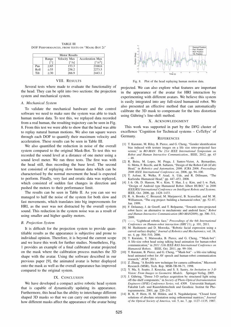
TABLE IIIDOF PERFORMANCES, FROM TESTS ON “MASK-BOT 2I”
Motor ResultsRange Velocity Max Acceleration Max
[◦] [◦/s] [◦/s2]Pan ±65 153.3 2168.6Roll ±55 258.2 2273.5Tilt ±30 266.9 2443.1
VIII. RESULTS
Several tests where made to evaluate the functionality ofthe head. They can be split into two sections: the projectionsystem and mechanical system.
A. Mechanical System
To validate the mechanical hardware and the controlsoftware we need to make sure the system was able to trackhuman motion data. To test this, we replayed data recordedfrom a real human, the resulting trajectory can be seen in Fig.8. From this test we were able to show that the head was ableto replay natural human motions. We also ran square wavesthrough each DOF to quantify their maximum velocity andacceleration. These results can be seen in Table III.
We also quantified the reduction in noise of the overallsystem compared to the original Mask-Bot. To test this werecorded the sound level at a distance of one meter using asound level meter. We ran three tests. The first was withthe head still, thus recording the base level. The secondtest consisted of replaying slow human data which can becharacterised by the normal movement the head is expectedto perform. Finally, very fast and erratic data was replayed,which consisted of sudden fast changes in direction andpushed the motors to their performance limit.
The results can be seen in Table II. As you can see wemanaged to half the noise of the system for both slow andfast movements, which translates into big improvements forHRI, as the user was not distracted by the overall systemsound. This reduction in the system noise was as a result ofusing smaller and higher quality motors.
B. Projection System
It is difficult for the projection system to provide quan-tifiable results as the appearance is subjective and prone toindividual opinion. Therefore, it is beyond the current scopeand we leave this work for further studies. Nonetheless, Fig.1 provides an example of a final calibrated avatar projectedon the mask where the calibration process matches the 3Dshape with the avatar. Using the software described in ourprevious paper [9], the animated avatar is better displayedonto the mask as well as the overall appearance has improvedcompared to the original system.
IX. CONCLUSION
We have developed a compact active robotic head systemthat is capable of dynamically updating its appearance.Furthermore, this head has the ability to interchange differentshaped 3D masks so that we can carry out experiments intohow different masks affect the appearance of the avatar being
0 5 10 15 20 25 30 35 40−40
−30
−20
−10
0
10
20
30
40
50
Time (s)
Po
sitio
n (
De
g)
Desired Position
Pan: Position
Roll: Position
Tilt: Position
Fig. 8. Plot of the head replaying human motion data.
projected. We can also explore what features are importantin the appearance of the avatar for HRI interaction byexperimenting with different avatars. We believe this systemis easily integrated into any full-sized humanoid robot. Wealso presented an effective method that can automaticallycalibrate the 3D mask to compensate for the lens distortionusing Guhring’s line-shift method.
X. ACKNOWLEDGMENT
This work was supported in part by the DFG cluster ofexcellence ’Cognition for Technical systems – CoTeSys’ ofGermany. REFERENCES
[1] T. Kuratate, M. Riley, B. Pierce, and G. Cheng, “Gender identificationbias induced with texture images on a life size retro-projected facescreen,” in RO-MAN: The 21st IEEE International Symposium onRobot and Human Interactive Communication., IEEE, 2012, pp. 43– 48.
[2] R. Beira, M. Lopes, M. Praga, J. Santos-Victor, A. Bernardino,G. Metta, F. Becchi, and R. Saltaren, “Design of the Robot-Cub (iCub)Head,” in Robotics and Automation, 2006. ICRA 2006. Proceedings2006 IEEE International Conference on, 2006, pp. 94–100.
[3] T. Asfour, K. Welke, P. Azad, A. Ude, and R. Dillmann, “TheKarlsruhe Humanoid Head,” pp. 447–453, 2008.
[4] J.-h. Oh, D. Hanson, W.-s. Kim, Y. Han, J.-y. Kim, and I.-w. Park,“Design of Android type Humanoid Robot Albert HUBO,” in 2006IEEE/RSJ International Conference on Intelligent Robots and Systems.IEEE, Oct. 2006, pp. 1428–1433.
[5] R. A. Brooks, C. Breazeal, M. Marjanovic, B. Scassellati, and M. M.Williamson, “The cog project: building a humanoid robot,” pp. 52–87,Jan. 1999.
[6] F. Delaunay, J. de Greeff, and T. Belpaeme, “Towards retro-projectedrobot faces: an alternative to mechatronic and android faces,” Robotand Human Interactive Communication (RO-MAN2009), pp. 306–311,2009.
[7] ——, “Lighthead robotic face,” Proceedings of the 6th InternationalConference on Human-robot interaction (HRI’11), p. 101, 2011.
[8] M. Hashimoto and D. Morooka, “Robotic facial expression using acurved surface display,” Journal of Robotics and Mechatronics, vol. 18,no. 4, pp. 504–510, 2006.
[9] T. Kuratate, Y. Matsusaka, B. Pierce, and G. Cheng, ““Mask-bot”:A life-size robot head using talking head animation for human-robotcommunication,” in 2011 11th IEEE-RAS International Conference onHumanoid Robots. IEEE, Oct. 2011, pp. 99–104.
[10] T. Kuratate, B. Pierce, and G. Cheng, “”Mask-bot” - a life-size talkinghead animated robot for AV speech and human-robot communicationresearch,” AVSP, 2011.
[11] Z. Zhang, “A flexible new technique for camera calibration,” MicrosoftResearch (MSR), Tech. Rep. MSR-TR-98-71, 1998.
[12] Y. Ma, S. Soatto, J. Kosecka, and S. S. Sastry, An Invitation to 3-DVision: From Images to Geometric Models. Springer-Verlag, 2005.
[13] J. Guhring, “Dense 3-D surface acquisition by structured light usingoff-the-shelf components,” in Society of Photo-Optical InstrumentationEngineers (SPIE) Conference Series, vol. 4309. Universitat Stuttgart;Fakultat Luft- und Raumfahrttechnik und Geodasie. Institut fur Pho-togrammetrie, 2001, pp. 220–231.
[14] B. K. P. Horn, H. M. Hilden, and S. Negahdaripour, “Closed formsolutions of absolute orientation using orthonormal matrices,” Journalof the Optical Society of America, vol. 5, no. 7, pp. 1127–1135, 1987.
525