maryland department of...
TRANSCRIPT

Maryland Department of Transportation
State Highway Administration Baltimore, Maryland
Invitation for Bids
Minority Business Enterprises are encouraged to respond to this Solicitation Notice.
The State Highway Administration will only be responsible for the completeness of documents obtained directly from the State Highway Administration Cashier’s Office.
Failure to attach all addenda may cause the bid to be irregular.
VENDOR I.D. NUMBER
S.H.A. USE ONLY
Contract No. HA2705171
F.A.P No. AC/STP-PLH-HP-4299(001)N & TIP-4299(002)N
US 40 – Interchange
at South Philadelphia Boulevard (US 40) and Short Lane (MD 715)
Design-Build

CONTRACT NO. HA2705171
TABLE OF CONTENTS
03-03-10
Invitation for Bids ............................................................................................................. Cover
Notice To Contractor - Pre-Proposal & Pre-Bidding Sessions ................................................. i
Table of Contents ...................................................................................................................... i
CONTRACT PROVISIONS
CP - (NCHRP) Report 350 Implementation Schedule .............................................................1
CP - Occupying Wetlands/Waterways for Design-Build .........................................................3
CP - Form FHWA 1273 ............................................................................................................6
CP - Affirmative Action Requirements Utilization Of Disadvantaged Business Enterprises For Federal-Aid Contracts ............................................................................................16
CP - Notice To Contractors Concerning The MBE/DBE Goal On This Contract .....................................................26
CP - MBE/DBE Compliance Field Meeting ..........................................................................27
CP-Traffic Control Plan Certification For Design-Build ......................................................28
CP - Prevailing Wage Instructions For The Contractor .......................................................................................................29
CP - Wage Determination for Harford County .......................................................................32
CP - Notice Of Actions For Affirmative Action Ensure Equal Employment Opportunity (Executive Order 11246) ...............................38
CP - Training Provisions ........................................................................................................46
CP - High Visibility Safety Apparel Policy ............................................................................50
CP - Specifications ................................................................................................................52
SP Project Description, Specifications, and Employment Agency .......................................55
SP - Notice to Contractor ........................................................................................................56
SP - Notice to Contractor ........................................................................................................59

CONTRACT NO. HA2705171
TABLE OF CONTENTS
03-03-10
TERMS AND CONDITIONS
TC - Section 2 - Bidding Requirements and Conditions for Design Build ............................60
TC - Section 2 - Stipend Agreement .......................................................................................92
TC - Section 3 - Scope of Work for Design-Build .................................................................97
TC - Section 4 - Control of Work For Detail.Build ..............................................................340
TC - Section 5 - Legal Relations and Progress for Design-Build .........................................342
TC - Section 6.10 - Recycled or Rehandled Materials .........................................................347
TC - Section 7 - Payment for Design-Build .........................................................................348
CATEGORY 100 PRELIMINARY
SP - Section 102 - Removal And Disposal Of Above Ground Storage Tanks .....................356
SP - Section 102 - Removal And Disposal Of Underground Storage Tanks .......................358
SPI - Section 103 - Engineers Office ....................................................................................360
SP - Section 103 - Engineers Office .....................................................................................361
SP - Section 104 Maintenance of Traffic 104.01 - Traffic Control Plan (TCP) ...........................................................................364
SP - Section 104 - Maintenance of Traffic 104.11 - Temporary Pavement Markings .....................................................................367
SPI - Section 104 - Maintenance of Traffic 104.14 - Cones for Maintenance of Traffic ..................................................................369
SP - Section 104 - Maintenance of Traffic 104.21 - Cellular Telephones .......................................................................................370
SPI - Section 104 - Maintenance of Traffic 104.25 - Drone Radar ...................................................................................................371
SPI - Section 104 - Maintenance of Traffic 104.30 - Portable Traffic Signal (PTS) .........................................................................372
SPI - Section 104 - Maintenance of Traffic 104.31 - Accessible Pedestrian Maintenance of Traffic ...............................................376

CONTRACT NO. HA2705171
TABLE OF CONTENTS
03-03-10
SP - Section 107 - Construction Stakeout ............................................................................378
SP - Section 112 - Critical Path Method Project Schedule Design-Build ............................383
SP - Section 113 - Digital Camera ........................................................................................390
CATEGORY 200 GRADING
SP - Section 201 - Roadway Excavation Class 1, Class 1-A, Class 2) ................................392
SP - Section 203 - Borrow Excavation 203.01.02 Notice to Contractor - Borrow Pits .............................................................393
CATEGORY 300 DRAINAGE
SP - Section 300 - Access Maintenance Road For SWM Pond ...........................................396
SP - Section 300 - Clay Backfill For Core Trench ...............................................................399
SP - Section 300 - Riser Structure ........................................................................................400
SP - Section 300 - Stormwater Management As-Built Certification ....................................401
SP - Section 300 - Stormwater Management Visual Quality Monitor .................................402
SP - Category 300 - Drainage Bulkhead and Abandon Existing Pipe .........................................................................404
SPI - Section 303 - Pipe Culverts .........................................................................................405
SP - Section 300 - Miscellaneous Structures ........................................................................406
SP - Section 300 - Erosion And Sediment Control ...............................................................407
SP - Section 300 Drainage 308 - Erosion and Sediment Control ...........................................................................408
SP - Section 314 Flowable Backfill ....................................................................................409
SPI - Section 316 - Stormwater Filtration Facilities .............................................................410
CATEGORY 400 STRUCTURES
SP - Section 400 - Joint Sealer ............................................................................................414
SP - Section 400 - Ornamental Fence For Structures ..........................................................415

CONTRACT NO. HA2705171
TABLE OF CONTENTS
03-03-10
SPI - Section 405 - Removal of Existing Structures .............................................................417
SP - Section 435 - Cleaning And Painting New Structural Steel ........................................419
SP - Section 450 - Retaining Walls .....................................................................................420
SP - Section 456 - Architectural Treatment ..........................................................................421
SP - SECTION 456 - Architectural Treatment .....................................................................425
SP - Section 499 - Working Drawings .................................................................................427

CONTRACT NO. HA2705171
TABLE OF CONTENTS
03-03-10
CATEGORY 500 PAVING
SP - Section 504 - Hot Mix Asphalt Pavement 504.04.01 Price Adjustment for Asphalt Binder ..........................................................429
SP - Section 504 - Hot Mix Asphalt Pavement 504.04.02 Payment Adjustments for Pavement Density and Hot Mix Asphalt Mixture ......................................................................................430
SPI - Section 504 - Hot Mix Asphalt Pavement ...................................................................433
SP - Section 505 - Hot Mix Asphalt Patches MD 715 AMTRAK Bridge ...........................434
SPI - Section 505-Hot Mix Asphalt Patches.........................................................................436
SPI-Section 506-Gap Graded Stone Matrix Asphalt ............................................................437
SP - Section 520 - Plain and reinforced Portland cement concrete pavements ....................441
SPI - Section 522 - Portland Cement Pavement Repairs ......................................................443
SP - Section 550 - Pavement Marking Paint .......................................................................444
SP - Section 552 Epoxy Pavement Marking ........................................................................446
SP - Section 553 Lead Free Reflective Thermoplastic Pavement Markings .............................................................................448
SP - Section 556 - Preformed Thermoplastic Pavement Markings ......................................451
SP-557 Snowplowable Raised Pavement Markers ...............................................................453
SP-558 RECESSED PAVEMENT MARKERS ..................................................................456
SP - Section 559 Permanent Preformed Patterned Reflective Pavement Markings .....................................................................................459
SP - Section 565 - Removal of Existing Pavement Markings ..............................................462
CATEGORY 700 LANDSCAPING
SPI-Section 709-Soil Stabilization Matting ..........................................................................464
CATEGORY 800 TRAFFIC

CONTRACT NO. HA2705171
TABLE OF CONTENTS
03-03-10
SP - Section 800 - Catalog Cuts and Working Drawings .....................................................466
SP - Section 800 - Coating New Galvanized Structures .......................................................471
SP - Section 800 - Wood Poles - Class II .............................................................................473
SP - Section 800 - Galvanized Traffic Signal Ped. Poles and Transformer Bases ...............476
SP - Section 800 - LED Sign Luminaires .............................................................................481
SP - Section 800 - LED Traffic Signal Modules ..................................................................483
SP - Section 800 - Mast Arms and Mast Arm Poles.............................................................489
SP - Section 800 - Non-Invasive Microloop Detectors ........................................................501
SP - Section 800 - Painting Weathered Galvanized Structures ...........................................504
SP - Section 800 - Red Signal Ahead Signs .........................................................................506
SP - Section 800 - Signal Equipment Turn On, Pick-Up, Removal and Maintenance .........509
SP - Section 800 - Sign Lighting Maintenance System ........................................................512
SP - Section 800 - IP-Based Video Traffic Detection Cameras ..........................................514
SP - Section 800 - Utility Connections and Utility Stakeout ...............................................521
SP - Section 800 - Galvanized Steel Beam Sign Posts .........................................................523
SP - Section 808 - Lighting Structures ................................................................................524
SP - Section 810 - Cable Duct End Seals .............................................................................528
SP - Section 814 - Signal Heads ...........................................................................................529
SP - Section 819 - Steel Span Wire ......................................................................................530
SP - Section 822 - Remove and Relocate Existing Signs .....................................................531
CATEGORY 900 MATERIALS
SPI - Section 900.03 - Recycled Materials ...........................................................................532
SPI - Section 901-Aggregates 901.05 - Stones for Gabions .........................................................................................536

CONTRACT NO. HA2705171
TABLE OF CONTENTS
03-03-10
SPI-Section 902 - Portland Cement Concrete and Related Products ...................................537
SPI -Section 908 - Reinforcement Steel ...............................................................................552
SPI-Section 916 - Soil and Soil-Aggregate Borrow .............................................................553
SPI - Section 920 - Landscaping ..........................................................................................554
SPI - Section 925 - Detectable Warning Surfaces ................................................................558
SP-Section 950.06-Electrical Cable And Wire ....................................................................560
SECTION 950 TRAFFIC MATERIALS
SP - Section 950 - Traffic Materials 950.15 - Traffic Signal Heads .......................................................................................561
SP - Section 951 - Pavement Marking Materials 951.04 - Removable Pavement Marking Tape .............................................................563
SP - Section 951 - Pavement Marking Materials 951.05 Snowplowable Raised Pavement Markers and Recessed Pavement Markers ..566
SP - Section 951 - Pavement Marking Materials 951.06 Heat Applied Permanent Preformed Thermoplastic Pavement Marking Materials ........................................................................................569
SP - Section 951 - Pavement Marking Materials 951.07 Permanent Preformed Patterned Reflective Pavement (PPPRP) Marking Material ..........................................................................................................................571
SP - Section 951- Pavement Marking Materials 951.08 - Lead Free Epoxy Marking Materials ...........................................................573
PROPOSAL FORM PACKET
CP Proposal Form Packet - Federal ......................................................................................578
CONTRACT PROVISIONS CONTRACT NO. HA2705171 (NCHRP) REPORT 350 IMPLEMENTATION SCHEDULE 1 of 2
08-04-09
Maryland Department of Transportation State Highway Administration
NOTICE TO ALL HOLDERS OF THIS CONTRACT DOCUMENT
NATIONAL COOPERATIVE HIGHWAY RESEARCH PROGRAM (NCHRP) REPORT 350 IMPLEMENTATION SCHEDULE FOR DEVICES USED IN THE
MAINTENANCE OF TRAFFIC Except as otherwise specified in this Section, all items for the maintenance of traffic, including those listed under the following categories, shall be crashworthy in conformance with Level 3 or other Level as specified by the Engineer in conformance with the safety crash testing and performance criteria published in the National Cooperative Highway Research Program (NCHRP) Report 350, “Recommended Procedures for the Safety Performance Evaluation of Highway Features.” When conformance with NCHRP Report 350 is required, the Contractor shall provide the Engineer with the manufacturers’ certifications that the devices comply with the specified criteria. Unless specifically waived by an attachment to these Contract Provisions, devices must be approved by the Office of Traffic and Safety. Category 1 Devices These devices are cones, tubular markers, flexible delineator posts, and drums, all without any accessories or attachments, which are used for channelization and delineation. Category 2 Devices These devices are Type I, II, and III barricades; portable sign supports with signs; intrusion alarms; and drums, vertical panels, and cones, all with accessories or attachments. Category 3 Devices (a) Truck Mounted Attenuators (TMAs) and Trailer Truck Mounted Attenuators (TTMAs) . (b) Temporary Barrier. (1) Concrete Barrier. (2) Traffic Barrier W Beam and Water Filled Barrier. (3) Steel/Aluminum Barrier. (c) Temporary End Treatments. Category 4 Devices These devices are area lighting supports, arrow panels, and portable variable message signs that are usually portable or trailer-mounted.
CONTRACT PROVISIONS CONTRACT NO.HA2705171 (NCHRP) REPORT 350 IMPLEMENTATION SCHEDULE 2 of 2
08-04-09
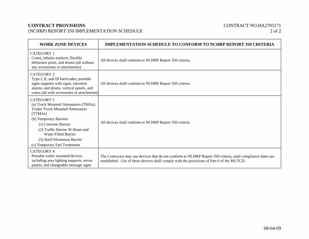
WORK ZONE DEVICES IMPLEMENTATION SCHEDULE TO CONFORM TO NCHRP REPORT 350 CRITERIA
CATEGORY 1 Cones, tubular markers, flexible delineator posts, and drums (all without any accessories or attachments)
All devices shall conform to NCHRP Report 350 criteria.
CATEGORY 2 Type I, II, and III barricades; portable signs supports with signs; intrusion alarms; and drums, vertical panels, and cones (all with accessories or attachments)
All devices shall conform to NCHRP Report 350 criteria.
CATEGORY 3 (a) Truck Mounted Attenuators (TMAs); Trailer Truck Mounted Attenuators (TTMAs) (b) Temporary Barriers
(1) Concrete Barrier (2) Traffic Barrier W Beam and
Water Filled Barrier (3) Steel/Aluminum Barrier
(c) Temporary End Treatments
All devices shall conform to NCHRP Report 350 criteria.
CATEGORY 4 Portable trailer mounted devices including area lighting supports, arrow panels, and changeable message signs
The Contractor may use devices that do not conform to NCHRP Report 350 criteria, until compliance dates are established. Use of these devices shall comply with the provisions of Part 6 of the MUTCD.

CONTRACT PROVISIONS (Revised) CONTRACT NO. HA2705171 Page 1 of 3
7-09-08
OCCUPYING WETLANDS/WATERWAYS FOR DESIGN-BUILD The Contractor is hereby alerted to the importance of preserving waterways and wetland areas. The Administration, in conjunction with the various environmental agencies, has developed these Contract Documents so as to minimize or eliminate disturbance and damage to existing waterways and wetland areas. Any design changes must result in further avoidance and minimization of disturbance of wetlands and waterways. In order to accomplish this, the following must be rigidly adhered to: (a) Prior to performing any work on the project, the areas of wetland will be identified and
marked by orange safety fence or as directed by the Engineer. All personnel of the Contractor or sub-contractors shall be alerted to these designated areas.
(b) The Contractor or sub-contractors shall not impact any wetland or waterway, whether it be
permanently or temporarily unless otherwise stipulated in the permit and approved as an authorized action by the appropriate regulatory agency. No fill shall be placed in these areas without an appropriate permit. No storage of equipment or materials will be allowed in wetlands.
(c) The Contractor or sub-contractor shall not impact a wetland or waterway that is not covered
by an existing wetland permit. (d) If the Contractor impacts any wetland or waterway for which they do not have a wetland
permit, they shall be responsible for contacting the State Highway Administration’s Environmental Programs Division prior to restoring the wetland areas and mitigating the wetland impacts to the full satisfaction of the environment regulatory agencies, which could include monetary compensation.
(e) The cost of restoration and mitigation of the impacted areas shall be at no additional cost to
the Administration.
(f) The Design-Builder will prepare permit modifications at the conclusion design and at the conclusion of construction. The modification will be based on surveyed as-built plans and will include standard 8.5”x 11.0” plates and a revised Joint State/Federal Nontidal Wetlands and Waterways Permit application.
(g) This Contract may include the oversight of an Environmental Monitor supplied by the
Administration. His duties will be to make sure the Contractor abides by all conditions in the environmental permits. He will also assist the Contractor in developing ideas to minimize impacts to the wetlands. The Contractor will still be responsible for all violations occuring as stated above.
The importance of not abusing waterways and wetland areas cannot be overemphasized. It is possible that abuse of waterways and wetland areas could jeopardize the operation of the total Contract and could be cause for a shut-down. If a shut-down occurs because of the Contractor's failure to secure the required permits(i.e. the Contractor’s method of work includes impacts not approved by previously acquired permits), the Contractor’s negligence or operations, all costs and damages to the Contractor and to the State will be at the Contractor's expense. Non-compliance with these requirements will not be considered for an extension of Contract time.

CONTRACT PROVISIONS (Revised) CONTRACT NO. HA2705171 Page 2 of 3
7-09-08
BEST MANAGEMENT PRACTICES FOR WORKING IN NONTIDAL WETLANDS, WETLAND BUFFERS, WATERWAYS, AND 100-YEAR FLOODPLAINS 1. NO EXCESS FILL, CONSTRUCTION MATERIAL, OR DEBRIS SHALL BE
STOCKPILED OR STORED IN NONTIDAL WETLANDS, NONTIDAL WETLAND BUFFERS, WATERWAYS, OR THE 100-YEAR FLOODPLAIN.
2. PLACE MATERIALS IN A LOCATION AND MANNER WHICH DOES NOT
ADVERSELY IMPACT SURFACE OR SUBSURFACE WATER FLOW INTO OR OUT OF NONTIDAL WETLANDS, NONTIDAL WETLAND BUFFERS, WATERWAYS, OR THE 100-YEAR FLOODPLAIN.
3. DO NOT USE THE EXCAVATED MATERIAL AS BACKFILL IF IT CONTAINS
WASTE METAL PRODUCTS, UNSIGHTLY DEBRIS, TOXIC MATERIAL, OR ANY OTHER DELETERIOUS SUBSTANCE. IF ADDITIONAL BACKFILL IS REQUIRED, USE CLEAN MATERIALS FREE OF WASTE METAL PRODUCTS, UNSIGHTLY DEBRIS, TOXIC MATERIAL, OR ANY OTHER DELETERIOUS SUBSTANCE.
4. PLACE HEAVY EQUIPMENT ON MATS OR SUITABLY OPERATE THE EQUIPMENT
TO PREVENT DAMAGE TO NONTIDAL WETLANDS, NONTIDAL WETLAND BUFFERS, WATERWAYS, OR THE 100-YEAR FLOODPLAIN.
5. REPAIR AND MAINTAIN ANY SERVICEABLE STRUCTURE OR FILL SO THERE IS
NO PERMANENT LOSS OF NONTIDAL WETLANDS, NONTIDAL WETLAND BUFFERS, OR WATERWAYS, OR PERMANENT MODIFICATION OF THE 100-YEAR FLOODPLAIN IN EXCESS OF THAT LOST UNDER THE ORIGINALLY AUTHORIZED STRUCTURE OR FILL.
6. RECTIFY ANY NONTIDAL WETLANDS, WETLAND BUFFERS, WATERWAYS, OR
100-YEAR FLOODPLAIN TEMPORARILY IMPACTED BY ANY CONSTRUCTION. 7. ALL STABILIZATION IN THE NONTIDAL WETLAND AND NONTIDAL WETLAND
BUFFER SHALL CONSIST OF THE FOLLOWING SPECIES:
ANNUAL RYEGRASS (LOLIUM MULTIFLORUM), MILLET (SETARIA ITALICA), BARLEY (HORDEUM SP.), OATS (UNIOLA SP.)AND/OR RYE (SECALE CEREALE). THESE SPECIES WILL ALLOW FOR THE STABILIZATIONOF THE SITE WHILE ALSO ALLOWING FOR THE
VOLUNTARY REVEGETATION OF NATURAL WETLAND SPECIES. OTHER NON-PERSISTENT VEGETATION MAY BE ACCEPTABLE, BUT

CONTRACT PROVISIONS (Revised) CONTRACT NO. HA2705171 Page 3 of 3
7-09-08
MUST BE APPROVED BY THE NONTIDAL WETLANDS AND WATERWAYS DIVISION. KENTUCKY 31 FESCUE SHALL NOT BE UTILIZED IN WETLAND OR BUFFER AREAS. THE AREA SHOULD BE SEEDED AND MULCHED TO REDUCE EROSION AFTER CONSTRUCTION ACTIVITIES HAVE BEEN COMPLETED.
8. AFTER INSTALLATION HAS BEEN COMPLETED, MAKE POST CONSTRUCTION
GRADES AND ELEVATIONS THE SAME AS THE ORIGINAL GRADES AND ELEVATIONS IN TEMPORARILY IMPACTED AREAS.
9. TO PROTECT AQUATIC SPECIES, IN-STREAM WORK IS PROHIBITED AS
DETERMINED BY THE CLASSIFICATION OF THE STREAM:
A. USE I WATERS: IN-STREAM WORK SHALL NOT BE CONDUCTED DURING THE PERIOD MARCH 1 THROUGH JUNE 15, INCLUSIVE DURING ANY YEAR.
B. USE III WATERS: IN-STREAM WORK SHALL NOT BE CONDUCTED DURING THE PERIOD OCTOBER 1 THORUGH APRIL 30, INCLUSIVE, DURING ANY YEAR.
C. USE IV WATERS: IN-STREAM WORK SHALL NOT BE CONDUCTED DURING THE PERIOD MARCH 1 THROUGH MAY 31, INCLUSIVE, DURING ANY YEAR.
10. STORMWATER RUNOFF FROM IMPERVIOUS SURFACES SHALL BE
CONTROLLED TO PREVENT THE WASHING OF DEBRIS INTO THE WATERWAY. 11. CULVERTS SHALL BE CONSTRUCTED AND ANY RIPRAP PLACED SO AS NOT TO
OBSTRUCT THE MOVEMENT OF AQUATIC SPECIES, UNLESS THE PURPOSE OF THE ACTIVITY IS TO IMPOUND WATER.

Form FHWA 1273 March 10, 1994
REQUIRED CONTRACT PROVISIONS FEDERAL-AID CONSTRUCTION CONTRACTS ───────────────────────────────────────────────────────────────────
Page I. General ............................................................................ 1 II. Nondiscrimination ............................................................ 1 III. Nonsegregated Facilities ................................................. 3 IV. Payment of Predetermined Minimum Wage .................... 3 V. Statements and Payrolls .................................................. 6 VI. Record of Materials, Supplies, and Labor ....................... 6 VII. Subletting or Assigning the Contract ............................... 7 VIII. Safety: Accident Prevention ........................................... 7 IX. False Statements Concerning Highway Projects............. 7 X. Implementation of Clean Air Act and Federal Water Pollution Control Act ............................................. 8 XI. Certification Regarding Debarment, Suspension, Ineligibility, and Voluntary Exclusion ............................... 8 XII. Certification Regarding Use of Contract Funds for Lobbying ........................................................................... 9
ATTACHMENTS A. Employment Preference for Appalachian Contracts (included in Appalachian contracts only) I. GENERAL 1. These contract provisions shall apply to all work performed on the contract by the contractor's own organization and with the assistance of workers under the contractor's immediate superin-tendence and to all work performed on the contract by piecework, station work, or by subcontract. 2. Except as otherwise provided for in each section, the contractor shall insert in each subcontract all of the stipulations contained in these Required Contract Provisions, and further require their inclusion in any lower tier subcontract or purchase order that may in turn be made. The Required Contract Provisions shall not be incorporated by reference in any case. The prime contractor shall be responsible for compliance by any subcontractor or lower tier subcontractor with these Required Contract Provisions. 3. A breach of any of the stipulations contained in these Required Contract Provisions shall be sufficient grounds for termination of the contract. 4. A breach of the following clauses of the Required Contract Provisions may also be grounds for debarment as provided in 29 CFR 5.12: Section I, paragraph 2; Section IV, paragraphs 1, 2, 3, 4, and 7; Section V, paragraphs 1 and 2a through 2g. 5. Disputes arising out of the labor standards provisions of Section IV (except paragraph 5) and Section V of these Required Contract Provisions shall not be subject to the general disputes clause of this contract. Such disputes shall be resolved in accordance with the procedures of the U.S. Department of Labor (DOL) as set forth in 29 CFR 5, 6, and 7. Disputes within the meaning of this clause include disputes between the contractor (or any of its subcontractors) and the contracting agency, the DOL, or the contractor's employees or their representatives. 6. Selection of Labor: During the performance of this contract, the contractor shall not: a. discriminate against labor from any other State, possession, or territory of the United States (except for employment preference for Appalachian contracts, when applicable, as specified in Attachment A), or
b. employ convict labor for any purpose within the limits of the project unless it is labor performed by convicts who are on parole, supervised release, or probation. II. NONDISCRIMINATION (Applicable to all Federal-aid construction contracts and to all related subcontracts of $10,000 or more.) 1. Equal Employment Opportunity: Equal employment opportu-nity (EEO) requirements not to discriminate and to take affirmative action to assure equal opportunity as set forth under laws, executive orders, rules, regulations (28 CFR 35, 29 CFR 1630 and 41 CFR 60) and orders of the Secretary of Labor as modified by the provisions prescribed herein, and imposed pursuant to 23 U.S.C. 140 shall constitute the EEO and specific affirmative action standards for the contractor's project activities under this contract. The Equal Opportunity Construction Contract Specifications set forth under 41 CFR 60-4.3 and the provisions of the American Disabilities Act of 1990 (42 U.S.C. 12101 et seq.) set forth under 28 CFR 35 and 29 CFR 1630 are incorporated by reference in this contract. In the execution of this contract, the contractor agrees to comply with the following minimum specific requirement activities of EEO: a. The contractor will work with the State highway agency (SHA) and the Federal Government in carrying out EEO obligations and in their review of his/her activities under the contract. b. The contractor will accept as his operating policy the following statement: "It is the policy of this Company to assure that applicants are
employed, and that employees are treated during employment, without regard to their race, religion, sex, color, national origin, age or disability. Such action shall include: employment, upgrading, demotion, or transfer; recruitment or recruitment advertising; layoff or termination; rates of pay or other forms of compensation; and selection for training, including apprentice-ship, preapprenticeship, and/or on-the-job training."
2. EEO Officer: The contractor will designate and make known to the SHA contracting officers an EEO Officer who will have the responsibility for and must be capable of effectively administering and promoting an active contractor program of EEO and who must be assigned adequate authority and responsibility to do so. 3. Dissemination of Policy: All members of the contractor's staff who are authorized to hire, supervise, promote, and discharge employees, or who recommend such action, or who are substantially involved in such action, will be made fully cognizant of, and will implement, the contractor's EEO policy and contractual responsibili-ties to provide EEO in each grade and classification of employment. To ensure that the above agreement will be met, the following actions will be taken as a minimum:

a. Periodic meetings of supervisory and personnel office employees will be conducted before the start of work and then not less often than once every six months, at which time the contractor's EEO policy and its implementation will be reviewed and explained. The meetings will be conducted by the EEO Officer. b. All new supervisory or personnel office employees will be given a thorough indoctrination by the EEO Officer, covering all major aspects of the contractor's EEO obligations within thirty days following their reporting for duty with the contractor. c. All personnel who are engaged in direct recruitment for the project will be instructed by the EEO Officer in the contractor's procedures for locating and hiring minority group employees. d. Notices and posters setting forth the contractor's EEO policy will be placed in areas readily accessible to employees, applicants for employment and potential employees. e. The contractor's EEO policy and the procedures to implement such policy will be brought to the attention of employees by means of meetings, employee handbooks, or other appropriate means. 4. Recruitment: When advertising for employees, the contractor will include in all advertisements for employees the notation: "An Equal Opportunity Employer." All such advertisements will be placed in publications having a large circulation among minority groups in the area from which the project work force would normally be derived. a. The contractor will, unless precluded by a valid bargaining agreement, conduct systematic and direct recruitment through public and private employee referral sources likely to yield qualified minority group applicants. To meet this requirement, the contractor will identify sources of potential minority group employees, and establish with such identified sources procedures whereby minority group applicants may be referred to the contractor for employment consideration. b. In the event the contractor has a valid bargaining agree-ment providing for exclusive hiring hall referrals, he is expected to observe the provisions of that agreement to the extent that the system permits the contractor's compliance with EEO contract provisions. (The DOL has held that where implementation of such agreements have the effect of discriminating against minorities or women, or obligates the contractor to do the same, such implemen-tation violates Executive Order 11246, as amended.) c. The contractor will encourage his present employees to refer minority group applicants for employment. Information and procedures with regard to referring minority group applicants will be discussed with employees. 5. Personnel Actions: Wages, working conditions, and employ-ee benefits shall be established and administered, and personnel actions of every type, including hiring, upgrading, promotion, transfer, demotion, layoff, and termination, shall be taken without regard to race, color, religion, sex, national origin, age or disability. The following procedures shall be followed: a. The contractor will conduct periodic inspections of project sites to insure that working conditions and employee facilities do not indicate discriminatory treatment of project site personnel. b. The contractor will periodically evaluate the spread of wages paid within each classification to determine any evidence of discriminatory wage practices. c. The contractor will periodically review selected personnel actions in depth to determine whether there is evidence of discrimi-nation. Where evidence is found, the contractor will promptly take corrective action. If the review indicates that the discrimination may
extend beyond the actions reviewed, such corrective action shall include all affected persons. d. The contractor will promptly investigate all complaints of alleged discrimination made to the contractor in connection with his obligations under this contract, will attempt to resolve such com-plaints, and will take appropriate corrective action within a reasonable time. If the investigation indicates that the discrimination may affect persons other than the complainant, such corrective action shall include such other persons. Upon completion of each investigation, the contractor will inform every complainant of all of his avenues of appeal. 6. Training and Promotion: a. The contractor will assist in locating, qualifying, and increasing the skills of minority group and women employees, and applicants for employment. b. Consistent with the contractor's work force requirements and as permissible under Federal and State regulations, the contractor shall make full use of training programs, i.e., appren-ticeship, and on-the-job training programs for the geographical area of contract performance. Where feasible, 25 percent of apprentices or trainees in each occupation shall be in their first year of appren-ticeship or training. In the event a special provision for training is provided under this contract, this subparagraph will be superseded as indicated in the special provision. c. The contractor will advise employees and applicants for employment of available training programs and entrance require-ments for each. d. The contractor will periodically review the training and promotion potential of minority group and women employees and will encourage eligible employees to apply for such training and promotion. 7. Unions: If the contractor relies in whole or in part upon unions as a source of employees, the contractor will use his/her best efforts to obtain the cooperation of such unions to increase opportunities for minority groups and women within the unions, and to effect referrals by such unions of minority and female employees. Actions by the contractor either directly or through a contractor's association acting as agent will include the procedures set forth below: a. The contractor will use best efforts to develop, in coopera-tion with the unions, joint training programs aimed toward qualifying more minority group members and women for membership in the unions and increasing the skills of minority group employees and women so that they may qualify for higher paying employment. b. The contractor will use best efforts to incorporate an EEO clause into each union agreement to the end that such union will be contractually bound to refer applicants without regard to their race, color, religion, sex, national origin, age or disability.

c. The contractor is to obtain information as to the referral practices and policies of the labor union except that to the extent such information is within the exclusive possession of the labor union and such labor union refuses to furnish such information to the contractor, the contractor shall so certify to the SHA and shall set forth what efforts have been made to obtain such information. d. In the event the union is unable to provide the contractor with a reasonable flow of minority and women referrals within the time limit set forth in the collective bargaining agreement, the contractor will, through independent recruitment efforts, fill the employment vacancies without regard to race, color, religion, sex, national origin, age or disability; making full efforts to obtain qualified and/or qualifiable minority group persons and women. (The DOL has held that it shall be no excuse that the union with which the contractor has a collective bargaining agreement providing for exclusive referral failed to refer minority employees.) In the event the union referral practice prevents the contractor from meeting the obligations pursuant to Executive Order 11246, as amended, and these special provisions, such contractor shall immediately notify the SHA. 8. Selection of Subcontractors, Procurement of Materials and Leasing of Equipment: The contractor shall not discriminate on the grounds of race, color, religion, sex, national origin, age or disability in the selection and retention of subcontractors, including procure-ment of materials and leases of equipment. a. The contractor shall notify all potential subcontractors and suppliers of his/her EEO obligations under this contract. b. Disadvantaged business enterprises (DBE), as defined in 49 CFR 23, shall have equal opportunity to compete for and perform subcontracts which the contractor enters into pursuant to this contract. The contractor will use his best efforts to solicit bids from and to utilize DBE subcontractors or subcontractors with meaningful minority group and female representation among their employees. Contractors shall obtain lists of DBE construction firms from SHA personnel. c. The contractor will use his best efforts to ensure subcon-tractor compliance with their EEO obligations. 9. Records and Reports: The contractor shall keep such records as necessary to document compliance with the EEO requirements. Such records shall be retained for a period of three years following completion of the contract work and shall be available at reasonable times and places for inspection by authorized representatives of the SHA and the FHWA. a. The records kept by the contractor shall document the following: (1) The number of minority and non-minority group members and women employed in each work classification on the project; (2) The progress and efforts being made in cooperation with unions, when applicable, to increase employment opportunities for minorities and women; (3) The progress and efforts being made in locating, hiring, training, qualifying, and upgrading minority and female employees; and (4) The progress and efforts being made in securing the services of DBE subcontractors or subcontractors with meaningful minority and female representation among their employees. b. The contractors will submit an annual report to the SHA each July for the duration of the project, indicating the number of minority, women, and non-minority group employees currently engaged in each work classification required by the contract work. This information is to be reported on Form FHWA-1391. If on-thejob
training is being required by special provision, the contractor will be required to collect and report training data. III. NONSEGREGATED FACILITIES (Applicable to all Federal-aid construction contracts and to all related subcontracts of $10,000 or more.) a. By submission of this bid, the execution of this contract or subcontract, or the consummation of this material supply agreement or purchase order, as appropriate, the bidder, Federal-aid construc-tion contractor, subcontractor, material supplier, or vendor, as appro-priate, certifies that the firm does not maintain or provide for its employees any segregated facilities at any of its establishments, and that the firm does not permit its employees to perform their services at any location, under its control, where segregated facilities are maintained. The firm agrees that a breach of this certification is a violation of the EEO provisions of this contract. The firm further certifies that no employee will be denied access to adequate facilities on the basis of sex or disability. b. As used in this certification, the term "segregated facilities" means any waiting rooms, work areas, restrooms and washrooms, restaurants and other eating areas, timeclocks, locker rooms, and other storage or dressing areas, parking lots, drinking fountains, recreation or entertainment areas, transportation, and housing facilities provided for employees which are segregated by explicit directive, or are, in fact, segregated on the basis of race, color, religion, national origin, age or disability, because of habit, local custom, or otherwise. The only exception will be for the disabled when the demands for accessibility override (e.g. disabled parking). c. The contractor agrees that it has obtained or will obtain identical certification from proposed subcontractors or material suppliers prior to award of subcontracts or consummation of material supply agreements of $10,000 or more and that it will retain such certifications in its files. IV. PAYMENT OF PREDETERMINED MINIMUM WAGE (Applicable to all Federal-aid construction contracts exceeding $2,000 and to all related subcontracts, except for projects located on roadways classified as local roads or rural minor collectors, which are exempt.) 1. General: a. All mechanics and laborers employed or working upon the site of the work will be paid unconditionally and not less often than once a week and without subsequent deduction or rebate on any account [except such payroll deductions as are permitted by regulations (29 CFR 3) issued by the Secretary of Labor under the Copeland Act (40 U.S.C. 276c)] the full amounts of wages and bona fide fringe benefits (or cash equivalents thereof) due at time of payment. The payment shall be computed at wage rates not less than those contained in the wage determination of the Secretary of Labor (hereinafter "the wage determination") which is attached hereto and made a part hereof, regardless of any contractual relationship which may be alleged to exist between the contractor or its subcontractors and such laborers and mechanics. The wage determination (including any additional classifications and wage rates conformed under paragraph 2 of this Section IV

and the DOL poster (WH-1321) or Form FHWA-1495) shall be posted at all times by the contractor and its subcontractors at the site of the work in a prominent and accessible place where it can be easily seen by the workers. For the purpose of this Section, contributions made or costs reasonably anticipated for bona fide fringe benefits under Section 1(b)(2) of the Davis-Bacon Act (40 U.S.C. 276a) on behalf of laborers or mechanics are considered wages paid to such laborers or mechanics, subject to the provisions of Section IV, paragraph 3b, hereof. Also, for the purpose of this Section, regular contributions made or costs incurred for more than a weekly period (but not less often than quarterly) under plans, funds, or programs, which cover the particular weekly period, are deemed to be constructively made or incurred during such weekly period. Such laborers and mechanics shall be paid the appropriate wage rate and fringe benefits on the wage determination for the classification of work actually performed, without regard to skill, except as provided in paragraphs 4 and 5 of this Section IV. b. Laborers or mechanics performing work in more than one classification may be compensated at the rate specified for each classification for the time actually worked therein, provided, that the employer's payroll records accurately set forth the time spent in each classification in which work is performed. c. All rulings and interpretations of the Davis-Bacon Act and related acts contained in 29 CFR 1, 3, and 5 are herein incorporated by reference in this contract. 2. Classification: a. The SHA contracting officer shall require that any class of laborers or mechanics employed under the contract, which is not listed in the wage determination, shall be classified in conformance with the wage determination. b. The contracting officer shall approve an additional classification, wage rate and fringe benefits only when the following criteria have been met: (1) the work to be performed by the additional classifi-cation requested is not performed by a classification in the wage determination; (2) the additional classification is utilized in the area by the construction industry; (3) the proposed wage rate, including any bona fide fringe benefits, bears a reasonable relationship to the wage rates contained in the wage determination; and (4) with respect to helpers as defined in Section IV.4(c), when such a classification prevails in the area in which the work is performed. c. If the contractor or subcontractors, as appropriate, the laborers and mechanics (if known) to be employed in the additional classification or their representatives, and the contracting officer agree on the classification and wage rate (including the amount designated for fringe benefits where appropriate), a report of the action taken shall be sent by the contracting officer to the DOL, Administrator of the Wage and Hour Division, Employment Standards Administration, Washington, D.C. 20210. The Wage and Hour Administrator, or an authorized representative, will approve, modify, or disapprove every additional classification action within 30 days of receipt and so advise the contracting officer or will notify the contracting officer within the 30-day period that additional time is necessary. d. In the event the contractor or subcontractors, as appro-priate, the laborers or mechanics to be employed in the additional classification or their representatives, and the contracting officer do not agree on the proposed classification and wage rate (including the
amount designated for fringe benefits, where appropriate), the contracting officer shall refer the questions, including the views of all interested parties and the recommendation of the contracting officer, to the Wage and Hour Administrator for determination. Said Adminis-trator, or an authorized representative, will issue a determination within 30 days of receipt and so advise the contracting officer or will notify the contracting officer within the 30-day period that additional time is necessary e. The wage rate (including fringe benefits where appropriate) determined pursuant to paragraph 2c or 2d of this Section IV shall be paid to all workers performing work in the additional classification from the first day on which work is performed in the classification. 3. Payment of Fringe Benefits: a. Whenever the minimum wage rate prescribed in the contract for a class of laborers or mechanics includes a fringe benefit which is not expressed as an hourly rate, the contractor or subcontractors, as appropriate, shall either pay the benefit as stated in the wage determination or shall pay another bona fide fringe benefit or an hourly case equivalent thereof. b. If the contractor or subcontractor, as appropriate, does not make payments to a trustee or other third person, he/she may consider as a part of the wages of any laborer or mechanic the amount of any costs reasonably anticipated in providing bona fide fringe benefits under a plan or program, provided, that the Secretary of Labor has found, upon the written request of the contractor, that the applicable standards of the Davis-Bacon Act have been met. The Secretary of Labor may require the contractor to set aside in a separate account assets for the meeting of obligations under the plan or program. 4. Apprentices and Trainees (Programs of the U.S. DOL) and
Helpers: a. Apprentices: (1) Apprentices will be permitted to work at less than the predetermined rate for the work they performed when they are employed pursuant to and individually registered in a bona fide apprenticeship program registered with the DOL, Employment and Training Administration, Bureau of Apprenticeship and Training, or with a State apprenticeship agency recognized by the Bureau, or if a person is employed in his/her first 90 days of probationary employment as an apprentice in such an apprenticeship program, who is not individually registered in the program, but who has been certified by the Bureau of Apprenticeship and Training or a State apprenticeship agency (where appropriate) to be eligible for probationary employment as an apprentice. (2) The allowable ratio of apprentices to journeyman-level employees on the job site in any craft classification shall not be greater than the ratio permitted to the contractor as to the entire work force under the registered program. Any employee listed on a payroll at an apprentice wage rate, who is not registered or otherwise employed as stated above, shall be paid not less than the applicable wage rate listed in the wage determination for the classification of work actually performed. In addition, any apprentice performing work on the job site in excess of the ratio permitted under the registered program shall be paid not less than the applicable wage rate on the wage determination for the work
actually performed. Where a contractor or subcontractor is perform-ing construction on a project in a locality other than that in which its program is registered, the ratios and wage rates (expressed in percentages of the journeyman-level hourly rate) specified in the contractor's or subcontractor's registered program shall be observed. (3) Every apprentice must be paid at not less than the rate specified in the registered program for the apprentice's level of progress, expressed as a percentage of the journeyman-level hourly rate specified in the applicable wage determination. Apprentices shall be paid fringe benefits in accordance with the provisions of the apprenticeship program. If the apprenticeship program does not specify fringe benefits, apprentices must be paid the full amount of fringe benefits listed on the wage determination for the applicable classification. If the Administrator for the Wage and Hour Division determines that a different practice prevails for the applicable apprentice classification, fringes shall be paid in accordance with that determination. (4) In the event the Bureau of Apprenticeship and Training, or a State apprenticeship agency recognized by the Bureau, withdraws approval of an apprenticeship program, the contractor or subcontractor will no longer be permitted to utilize apprentices at less than the applicable predetermined rate for the comparable work performed by regular employees until an acceptable program is approved. b. Trainees: (1) Except as provided in 29 CFR 5.16, trainees will not be permitted to work at less than the predetermined rate for the work performed unless they are employed pursuant to and individually registered in a program which has received prior approval, evidenced by formal certification by the DOL, Employment and Training Administration. (2) The ratio of trainees to journeyman-level employees on the job site shall not be greater than permitted under the plan approved by the Employment and Training Administration. Any employee listed on the payroll at a trainee rate who is not registered and participating in a training plan approved by the Employment and Training Administration shall be paid not less than the applicable wage rate on the wage determination for the classification of work actually performed. In addition, any trainee performing work on the job site in excess of the ratio permitted under the registered program shall be paid not less than the applicable wage rate on the wage determination for the work actually performed. (3) Every trainee must be paid at not less than the rate specified in the approved program for his/her level of progress, expressed as a percentage of the journeyman-level hourly rate specified in the applicable wage determination. Trainees shall be paid fringe benefits in accordance with the provisions of the trainee program. If the trainee program does not mention fringe benefits, trainees shall be paid the full amount of fringe benefits listed on the wage determination unless the Administrator of the Wage and Hour Division determines that there is an apprenticeship program associated with the corresponding journeyman-level wage rate on the wage determination which provides for less than full fringe benefits for apprentices, in which case such trainees shall receive the same fringe benefits as apprentices. (4) In the event the Employment and Training Adminis-tration withdraws approval of a training program, the contractor or subcontractor will no longer be permitted to utilize trainees at less than the applicable predetermined rate for the work performed until an acceptable program is approved. c. Helpers: Helpers will be permitted to work on a project if the helper classification is specified on an applicable wage determination or is
approved pursuant to the conformance procedure set forth in Section IV.2. Any worker listed on a payroll at a helper wage rate, shall be paid not less than the applicable wage rate on the wage determi-nation for the classification of work actually performed. 5. Apprentices and Trainees (Programs of the U.S. DOT): Apprentices and trainees working under apprenticeship and skill training programs which have been certified by the Secretary of Transportation as promoting EEO in connection with Federal-aid highway construction programs are not subject to the requirements of paragraph 4 of this Section IV. The straight time hourly wage rates for apprentices and trainees under such programs will be established by the particular programs. The ratio of apprentices and trainees to journeymen shall not be greater than permitted by the terms of the particular program. 6. Withholding: The SHA shall upon its own action or upon written request of an authorized representative of the DOL withhold, or cause to be withheld, from the contractor or subcontractor under this contract or any other Federal contract with the same prime contractor, or any other Federally-assisted contract subject to Davis-Bacon prevailing wage requirements which is held by the same prime contractor, as much of the accrued payments or advances as may be considered necessary to pay laborers and mechanics, including apprentices, trainees, and helpers, employed by the contractor or any subcon-tractor the full amount of wages required by the contract. In the event of failure to pay any laborer or mechanic, including any apprentice, trainee, or helper, employed or working on the site of the work, all or part of the wages required by the contract, the SHA contracting officer may, after written notice to the contractor, take such action as may be necessary to cause the suspension of any further payment, advance, or guarantee of funds until such violations have ceased. 7. Overtime Requirements: No contractor or subcontractor contracting for any part of the contract work which may require or involve the employment of laborers, mechanics, watchmen, or guards (including apprentices, trainees, and helpers described in paragraphs 4 and 5 above) shall require or permit any laborer, mechanic, watchman, or guard in any workweek in which he/she is employed on such work, to work in excess of 40 hours in such workweek unless such laborer, mechanic, watchman, or guard receives compensation at a rate not less than one-and-one-half times his/her basic rate of pay for all hours worked in excess of 40 hours in such workweek. 8. Violation: Liability for Unpaid Wages; Liquidated Damages: In the event of any violation of the clause set forth in paragraph 7 above, the contractor and any subcontractor responsible thereof shall be liable to the affected employee for his/her unpaid wages. In addition, such contractor and subcontractor shall be liable to the United States (in the case of work done under contract for the District of Columbia or a territory, to such District or to such territory) for liquidated damages. Such liquidated damages shall be computed with respect to each individual laborer, mechanic, watchman, or guard employed in violation of the clause set forth in paragraph 7, in the sum of $10 for each calendar day on which

such employee was required or permitted to work in excess of the standard work week of 40 hours without payment of the overtime wages required by the clause set forth in paragraph 7. 9. Withholding for Unpaid Wages and Liquidated Damages: The SHA shall upon its own action or upon written request of any authorized representative of the DOL withhold, or cause to be withheld, from any monies payable on account of work performed by the contractor or subcontractor under any such contract or any other Federal contract with the same prime contractor, or any other Federally-assisted contract subject to the Contract Work Hours and Safety Standards Act, which is held by the same prime contractor, such sums as may be determined to be necessary to satisfy any liabilities of such contractor or subcontractor for unpaid wages and liquidated damages as provided in the clause set forth in paragraph 8 above. V. STATEMENTS AND PAYROLLS (Applicable to all Federal-aid construction contracts exceeding $2,000 and to all related subcontracts, except for projects located on roadways classified as local roads or rural collectors, which are exempt.) 1. Compliance with Copeland Regulations (29 CFR 3): The contractor shall comply with the Copeland Regulations of the Secretary of Labor which are herein incorporated by reference. 2. Payrolls and Payroll Records: a. Payrolls and basic records relating thereto shall be maintained by the contractor and each subcontractor during the course of the work and preserved for a period of 3 years from the date of completion of the contract for all laborers, mechanics, apprentices, trainees, watchmen, helpers, and guards working at the site of the work. b. The payroll records shall contain the name, social security number, and address of each such employee; his or her correct classification; hourly rates of wages paid (including rates of contributions or costs anticipated for bona fide fringe benefits or cash equivalent thereof the types described in Section 1(b)(2)(B) of the Davis Bacon Act); daily and weekly number of hours worked; deductions made; and actual wages paid. In addition, for Appala-chian contracts, the payroll records shall contain a notation indicating whether the employee does, or does not, normally reside in the labor area as defined in Attachment A, paragraph 1. Whenever the Secretary of Labor, pursuant to Section IV, paragraph 3b, has found that the wages of any laborer or mechanic include the amount of any costs reasonably anticipated in providing benefits under a plan or program described in Section 1(b)(2)(B) of the Davis Bacon Act, the contractor and each subcontractor shall maintain records which show that the commitment to provide such benefits is enforceable, that the plan or program is financially responsible, that the plan or program has been communicated in writing to the laborers or mechanics affected, and show the cost anticipated or the actual cost incurred in providing benefits. Contractors or subcontractors employing apprentices or trainees under approved programs shall maintain written evidence of the registration of apprentices and trainees, and ratios and wage rates prescribed in the applicable programs. c. Each contractor and subcontractor shall furnish, each week in which any contract work is performed, to the SHA resident engineer a payroll of wages paid each of its employees (including
apprentices, trainees, and helpers, described in Section IV, para-graphs 4 and 5, and watchmen and guards engaged on work during the preceding weekly payroll period). The payroll submitted shall set out accurately and completely all of the information required to be maintained under paragraph 2b of this Section V. This information may be submitted in any form desired. Optional Form WH-347 is available for this purpose and may be purchased from the Superintendent of Documents (Federal stock number 029-005-0014-1), U.S. Government Printing Office, Washington, D.C. 20402. The prime contractor is responsible for the submission of copies of payrolls by all subcontractors. d. Each payroll submitted shall be accompanied by a "Statement of Compliance," signed by the contractor or subcontractor or his/her agent who pays or supervises the payment of the persons employed under the contract and shall certify the following: (1) that the payroll for the payroll period contains the information required to be maintained under paragraph 2b of this Section V and that such information is correct and complete; (2) that such laborer or mechanic (including each helper, apprentice, and trainee) employed on the contract during the payroll period has been paid the full weekly wages earned, without rebate, either directly or indirectly, and that no deductions have been made either directly or indirectly from the full wages earned, other than permissible deductions as set forth in the Regulations, 29 CFR 3; (3) that each laborer or mechanic has been paid not less that the applicable wage rate and fringe benefits or cash equivalent for the classification of worked performed, as specified in the applicable wage determination incorporated into the contract. e. The weekly submission of a properly executed certification set forth on the reverse side of Optional Form WH-347 shall satisfy the requirement for submission of the "Statement of Compliance" required by paragraph 2d of this Section V. f. The falsification of any of the above certifications may subject the contractor to civil or criminal prosecution under 18 U.S.C. 1001 and 31 U.S.C. 231. g. The contractor or subcontractor shall make the records required under paragraph 2b of this Section V available for inspec-tion, copying, or transcription by authorized representatives of the SHA, the FHWA, or the DOL, and shall permit such representatives to interview employees during working hours on the job. If the contractor or subcontractor fails to submit the required records or to make them available, the SHA, the FHWA, the DOL, or all may, after written notice to the contractor, sponsor, applicant, or owner, take such actions as may be necessary to cause the suspension of any further payment, advance, or guarantee of funds. Furthermore, failure to submit the required records upon request or to make such records available may be grounds for debarment action pursuant to 29 CFR 5.12. VI. RECORD OF MATERIALS, SUPPLIES, AND LABOR 1. On all Federal-aid contracts on the National Highway System, except those which provide solely for the installation of protective devices at railroad grade crossings, those which are constructed on a force account or direct labor basis, highway beautification contracts, and contracts for which the total final construction cost for roadway and bridge is less than $1,000,000 (23 CFR 635) the contractor shall:

a. Become familiar with the list of specific materials and supplies contained in Form FHWA-47, "Statement of Materials and Labor Used by Contractor of Highway Construction Involving Federal Funds," prior to the commencement of work under this contract. b. Maintain a record of the total cost of all materials and supplies purchased for and incorporated in the work, and also of the quantities of those specific materials and supplies listed on Form FHWA-47, and in the units shown on Form FHWA-47. c. Furnish, upon the completion of the contract, to the SHA resident engineer on Form FHWA-47 together with the data required in paragraph 1b relative to materials and supplies, a final labor summary of all contract work indicating the total hours worked and the total amount earned. 2. At the prime contractor's option, either a single report covering all contract work or separate reports for the contractor and for each subcontract shall be submitted. VII. SUBLETTING OR ASSIGNING THE CONTRACT 1. The contractor shall perform with its own organization contract work amounting to not less than 30 percent (or a greater percentage if specified elsewhere in the contract) of the total original contract price, excluding any specialty items designated by the State. Specialty items may be performed by subcontract and the amount of any such specialty items performed may be deducted from the total original contract price before computing the amount of work required to be performed by the contractor's own organization (23 CFR 635). a. "Its own organization" shall be construed to include only workers employed and paid directly by the prime contractor and equipment owned or rented by the prime contractor, with or without operators. Such term does not include employees or equipment of a subcontractor, assignee, or agent of the prime contractor. b. "Specialty Items" shall be construed to be limited to work that requires highly specialized knowledge, abilities, or equipment not ordinarily available in the type of contracting organizations qualified and expected to bid on the contract as a whole and in general are to be limited to minor components of the overall contract. 2. The contract amount upon which the requirements set forth in paragraph 1 of Section VII is computed includes the cost of material and manufactured products which are to be purchased or produced by the contractor under the contract provisions. 3. The contractor shall furnish (a) a competent superintendent or supervisor who is employed by the firm, has full authority to direct performance of the work in accordance with the contract require-ments, and is in charge of all construction operations (regardless of who performs the work) and (b) such other of its own organizational resources (supervision, management, and engineering services) as the SHA contracting officer determines is necessary to assure the performance of the contract. 4. No portion of the contract shall be sublet, assigned or otherwise disposed of except with the written consent of the SHA contracting officer, or authorized representative, and such consent when given shall not be construed to relieve the contractor of any responsibility for the fulfillment of the contract. Written consent will be given only after the SHA has assured that each subcontract is evidenced in writing and that it contains all pertinent provisions and requirements of the prime contract. VIII. SAFETY: ACCIDENT PREVENTION
1. In the performance of this contract the contractor shall comply with all applicable Federal, State, and local laws governing safety, health, and sanitation (23 CFR 635). The contractor shall provide all safeguards, safety devices and protective equipment and take any other needed actions as it determines, or as the SHA contracting officer may determine, to be reasonably necessary to protect the life and health of employees on the job and the safety of the public and to protect property in connection with the performance of the work covered by the contract. 2. It is a condition of this contract, and shall be made a condition of each subcontract, which the contractor enters into pursuant to this contract, that the contractor and any subcontractor shall not permit any employee, in performance of the contract, to work in surround-ings or under conditions which are unsanitary, hazardous or dangerous to his/her health or safety, as determined under construction safety and health standards (29 CFR 1926) promulgated by the Secretary of Labor, in accordance with Section 107 of the Contract Work Hours and Safety Standards Act (40 U.S.C. 333). 3. Pursuant to 29 CFR 1926.3, it is a condition of this contract that the Secretary of Labor or authorized representative thereof, shall have right of entry to any site of contract performance to inspect or investigate the matter of compliance with the construction safety and health standards and to carry out the duties of the Secretary under Section 107 of the Contract Work Hours and Safety Standards Act (40 U.S.C. 333). IX. FALSE STATEMENTS CONCERNING HIGHWAY PROJECTS In order to assure high quality and durable construction in conformity with approved plans and specifications and a high degree of reliability on statements and representations made by engineers, contractors, suppliers, and workers on Federal-aid highway projects, it is essential that all persons concerned with the project perform their functions as carefully, thoroughly, and honestly as possible. Willful falsification, distortion, or misrepresentation with respect to any facts related to the project is a violation of Federal law. To prevent any misunderstanding regarding the seriousness of these and similar acts, the following notice shall be posted on each Federal-aid highway project (23 CFR 635) in one or more places where it is readily available to all persons concerned with the project:
NOTICE TO ALL PERSONNEL ENGAGED ON FEDERAL-AID HIGHWAY PROJECTS
18 U.S.C. 1020 reads as follows: "Whoever, being an officer, agent, or employee of the United States, or of any State or Territory, or whoever, whether a person, association, firm, or corporation, knowingly makes any false statement, false representation, or false report as to the character, quality, quantity, or cost of the material used or to be used, or the quantity or quality of the work performed or to be performed, or the cost thereof in connection with the submission of plans, maps, specifications, contracts, or costs of construction on any highway or related project submitted for approval to the Secretary of Transportation; or Whoever knowingly makes any false statement, false represen-tation, false report or false claim with respect to the character, quality, quantity, or cost of any work performed or to be performed,

or materials furnished or to be furnished, in connection with the construction of any highway or related project approved by the Secretary of Transportation; or Whoever knowingly makes any false statement or false repre-sentation as to material fact in any statement, certificate, or report submitted pursuant to provisions of the Federal-aid Roads Act approved July 1, 1916, (39 Stat. 355), as amended and supple-mented; Shall be fined not more that $10,000 or imprisoned not more than 5 years or both." X. IMPLEMENTATION OF CLEAN AIR ACT AND FEDERAL WATER POLLUTION CONTROL ACT (Applicable to all Federal-aid construction contracts and to all related subcontracts of $100,000 or more.) By submission of this bid or the execution of this contract, or subcontract, as appropriate, the bidder, Federal-aid construction contractor, or subcontractor, as appropriate, will be deemed to have stipulated as follows: 1. That any facility that is or will be utilized in the performance of this contract, unless such contract is exempt under the Clean Air Act, as amended (42 U.S.C. 1857 et seq., as amended by Pub.L. 91-604), and under the Federal Water Pollution Control Act, as amended (33 U.S.C. 1251 et seq., as amended by Pub.L. 92-500), Executive Order 11738, and regulations in implementation thereof (40 CFR 15) is not listed, on the date of contract award, on the U.S. Environmental Protection Agency (EPA) List of Violating Facilities pursuant to 40 CFR 15.20. 2. That the firm agrees to comply and remain in compliance with all the requirements of Section 114 of the Clean Air Act and Section 308 of the Federal Water Pollution Control Act and all regulations and guidelines listed thereunder. 3. That the firm shall promptly notify the SHA of the receipt of any communication from the Director, Office of Federal Activities, EPA, indicating that a facility that is or will be utilized for the contract is under consideration to be listed on the EPA List of Violating Facilities. 4. That the firm agrees to include or cause to be included the requirements of paragraph 1 through 4 of this Section X in every nonexempt subcontract, and further agrees to take such action as the government may direct as a means of enforcing such requirements. XI. CERTIFICATION REGARDING DEBARMENT, SUSPENSION, INELIGIBILITY AND VOLUNTARY EXCLUSION 1. Instructions for Certification - Primary Covered Transactions: (Applicable to all Federal-aid contracts - 49 CFR 29) a. By signing and submitting this proposal, the prospective primary participant is providing the certification set out below. b. The inability of a person to provide the certification set out below will not necessarily result in denial of participation in this covered transaction. The prospective participant shall submit an explanation of why it cannot provide the certification set out below. The certification or explanation will be considered in connection with the department or agency's determination whether to enter into this transaction. However, failure of the prospective primary participant to furnish a certification or an explanation shall disqualify such a person from participation in this transaction. c. The certification in this clause is a material representation of fact upon which reliance was placed when the department or agency
determined to enter into this transaction. If it is later determined that the prospective primary participant knowingly rendered an erroneous certification, in addition to other remedies available to the Federal Government, the department or agency may terminate this transaction for cause of default. d. The prospective primary participant shall provide immediate written notice to the department or agency to whom this proposal is submitted if any time the prospective primary participant learns that its certification was erroneous when submitted or has become erroneous by reason of changed circumstances. e. The terms "covered transaction," "debarred," "suspended," "ineligible," "lower tier covered transaction," "participant," "person," "primary covered transaction," "principal," "proposal," and "voluntarily excluded," as used in this clause, have the meanings set out in the Definitions and Coverage sections of rules implementing Executive Order 12549. You may contact the department or agency to which this proposal is submitted for assistance in obtaining a copy of those regulations. f. The prospective primary participant agrees by submitting this proposal that, should the proposed covered transaction be entered into, it shall not knowingly enter into any lower tier covered transaction with a person who is debarred, suspended, declared ineligible, or voluntarily excluded from participation in this covered transaction, unless authorized by the department or agency entering into this transaction. g. The prospective primary participant further agrees by submitting this proposal that it will include the clause titled "Certifi-cation Regarding Debarment, Suspension, Ineligibility and Voluntary Exclusion-Lower Tier Covered Transaction," provided by the department or agency entering into this covered transaction, without modification, in all lower tier covered transactions and in all solicitations for lower tier covered transactions. h. A participant in a covered transaction may rely upon a certification of a prospective participant in a lower tier covered transaction that is not debarred, suspended, ineligible, or voluntarily excluded from the covered transaction, unless it knows that the certification is erroneous. A participant may decide the method and frequency by which it determines the eligibility of its principals. Each participant may, but is not required to, check the nonprocurement portion of the "Lists of Parties Excluded From Federal Procurement or Nonprocurement Programs" (Nonprocurement List) which is compiled by the General Services Administration. i. Nothing contained in the foregoing shall be construed to require establishment of a system of records in order to render in good faith the certification required by this clause. The knowledge and information of participant is not required to exceed that which is normally possessed by a prudent person in the ordinary course of business dealings. j. Except for transactions authorized under paragraph f of these instructions, if a participant in a covered transaction knowingly enters into a lower tier covered transaction with a person who is suspended, debarred, ineligible, or voluntarily excluded from participation in this transaction, in addition to other remedies available to the Federal Government, the department or agency may terminate this transaction for cause or default.
* * * * *

Certification Regarding Debarment, Suspension, Ineligibility and Voluntary Exclusion--Primary Covered Transactions 1. The prospective primary participant certifies to the best of its knowledge and belief, that it and its principals: a. Are not presently debarred, suspended, proposed for debarment, declared ineligible, or voluntarily excluded from covered transactions by any Federal department or agency; b. Have not within a 3-year period preceding this proposal been convicted of or had a civil judgement rendered against them for commission of fraud or a criminal offense in connection with obtaining, attempting to obtain, or performing a public (Federal, State or local) transaction or contract under a public transaction; violation of Federal or State antitrust statutes or commission of embezzlement, theft, forgery, bribery, falsification or destruction of records, making false statements, or receiving stolen property; c. Are not presently indicted for or otherwise criminally or civilly charged by a governmental entity (Federal, State or local) with commission of any of the offenses enumerated in paragraph 1b of this certification; and d. Have not within a 3-year period preceding this applica-tion/proposal had one or more public transactions (Federal, State or local) terminated for cause or default. 2. Where the prospective primary participant is unable to certify to any of the statements in this certification, such prospective participant shall attach an explanation to this proposal.
* * * * * 2. Instructions for Certification - Lower Tier Covered Transactions: (Applicable to all subcontracts, purchase orders and other lower tier transactions of $25,000 or more - 49 CFR 29) a. By signing and submitting this proposal, the prospective lower tier is providing the certification set out below. b. The certification in this clause is a material representation of fact upon which reliance was placed when this transaction was entered into. If it is later determined that the prospective lower tier participant knowingly rendered an erroneous certification, in addition to other remedies available to the Federal Government, the depart-ment, or agency with which this transaction originated may pursue available remedies, including suspension and/or debarment. c. The prospective lower tier participant shall provide immediate written notice to the person to which this proposal is submitted if at any time the prospective lower tier participant learns that its certification was erroneous by reason of changed circum-stances. d. The terms "covered transaction," "debarred," "suspended," "ineligible," "primary covered transaction," "participant," "person," "principal," "proposal," and "voluntarily excluded," as used in this clause, have the meanings set out in the Definitions and Coverage sections of rules implementing Executive Order 12549. You may contact the person to which this proposal is submitted for assistance in obtaining a copy of those regulations. e. The prospective lower tier participant agrees by submitting this proposal that, should the proposed covered transaction be entered into, it shall not knowingly enter into any lower tier covered transaction with a person who is debarred, suspended, declared ineligible, or voluntarily excluded from participation in this covered transaction, unless authorized by the department or agency with which this transaction originated.
f. The prospective lower tier participant further agrees by submitting this proposal that it will include this clause titled "Certification Regarding Debarment, Suspension, Ineligibility and Voluntary Exclusion-Lower Tier Covered Transaction," without modification, in all lower tier covered transactions and in all solicitations for lower tier covered transactions. g. A participant in a covered transaction may rely upon a certification of a prospective participant in a lower tier covered transaction that is not debarred, suspended, ineligible, or voluntarily excluded from the covered transaction, unless it knows that the certification is erroneous. A participant may decide the method and frequency by which it determines the eligibility of its principals. Each participant may, but is not required to, check the Nonprocurement List. h. Nothing contained in the foregoing shall be construed to require establishment of a system of records in order to render in good faith the certification required by this clause. The knowledge and information of participant is not required to exceed that which is normally possessed by a prudent person in the ordinary course of business dealings. i. Except for transactions authorized under paragraph e of these instructions, if a participant in a covered transaction knowingly enters into a lower tier covered transaction with a person who is suspended, debarred, ineligible, or voluntarily excluded from participation in this transaction, in addition to other remedies available to the Federal Government, the department or agency with which this transaction originated may pursue available remedies, including suspension and/or debarment.
* * * * *
Certification Regarding Debarment, Suspension, Ineligibility and Voluntary Exclusion--Lower Tier Covered Transactions:
1. The prospective lower tier participant certifies, by submission of this proposal, that neither it nor its principals is presently debarred, suspended, proposed for debarment, declared ineligible, or voluntarily excluded from participation in this transaction by any Federal department or agency. 2. Where the prospective lower tier participant is unable to certify to any of the statements in this certification, such prospective participant shall attach an explanation to this proposal.
* * * * * XII. CERTIFICATION REGARDING USE OF CONTRACT FUNDS FOR LOBBYING (Applicable to all Federal-aid construction contracts and to all related subcontracts which exceed $100,000 - 49 CFR 20) 1. The prospective participant certifies, by signing and submitting this bid or proposal, to the best of his or her knowledge and belief, that:

a. No Federal appropriated funds have been paid or will be paid, by or on behalf of the undersigned, to any person for influencing or attempting to influence an officer or employee of any Federal agency, a Member of Congress, an officer or employee of Congress, or an employee of a Member of Congress in connection with the awarding of any Federal contract, the making of any Federal grant, the making of any Federal loan, the entering into of any cooperative agreement, and the extension, continuation, renewal, amendment, or modification of any Federal contract, grant, loan, or cooperative agreement. b. If any funds other than Federal appropriated funds have been paid or will be paid to any person for influencing or attempting to influence an officer or employee of any Federal agency, a Member of Congress, an officer or employee of Congress, or an employee of a Member of Congress in connection with this Federal contract, grant, loan, or cooperative agreement, the undersigned shall complete and submit Standard Form-LLL, "Disclosure Form to Report Lobbying," in accordance with its instructions. 2. This certification is a material representation of fact upon which reliance was placed when this transaction was made or entered into. Submission of this certification is a prerequisite for making or entering into this transaction imposed by 31 U.S.C. 1352. Any person who fails to file the required certification shall be subject to a civil penalty of not less than $10,000 and not more than $100,000 for each such failure. 3. The prospective participant also agrees by submitting his or her bid or proposal that he or she shall require that the language of this certification be included in all lower tier subcontracts, which exceed $100,000 and that all such recipients shall certify and disclose accordingly.
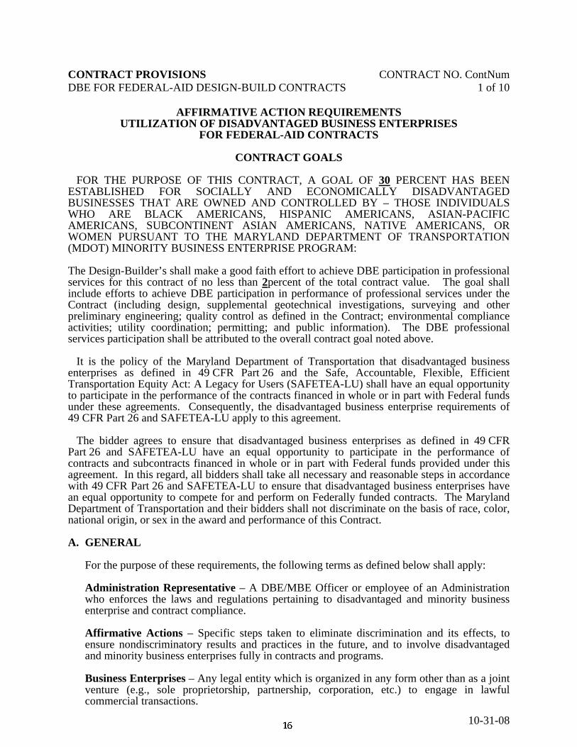
CONTRACT PROVISIONS CONTRACT NO. ContNum DBE FOR FEDERAL-AID DESIGN-BUILD CONTRACTS 1 of 10
10-31-08
AFFIRMATIVE ACTION REQUIREMENTS UTILIZATION OF DISADVANTAGED BUSINESS ENTERPRISES
FOR FEDERAL-AID CONTRACTS
CONTRACT GOALS FOR THE PURPOSE OF THIS CONTRACT, A GOAL OF 30 PERCENT HAS BEEN ESTABLISHED FOR SOCIALLY AND ECONOMICALLY DISADVANTAGED BUSINESSES THAT ARE OWNED AND CONTROLLED BY – THOSE INDIVIDUALS WHO ARE BLACK AMERICANS, HISPANIC AMERICANS, ASIAN-PACIFIC AMERICANS, SUBCONTINENT ASIAN AMERICANS, NATIVE AMERICANS, OR WOMEN PURSUANT TO THE MARYLAND DEPARTMENT OF TRANSPORTATION (MDOT) MINORITY BUSINESS ENTERPRISE PROGRAM: The Design-Builder’s shall make a good faith effort to achieve DBE participation in professional services for this contract of no less than 2percent of the total contract value. The goal shall include efforts to achieve DBE participation in performance of professional services under the Contract (including design, supplemental geotechnical investigations, surveying and other preliminary engineering; quality control as defined in the Contract; environmental compliance activities; utility coordination; permitting; and public information). The DBE professional services participation shall be attributed to the overall contract goal noted above. It is the policy of the Maryland Department of Transportation that disadvantaged business enterprises as defined in 49 CFR Part 26 and the Safe, Accountable, Flexible, Efficient Transportation Equity Act: A Legacy for Users (SAFETEA-LU) shall have an equal opportunity to participate in the performance of the contracts financed in whole or in part with Federal funds under these agreements. Consequently, the disadvantaged business enterprise requirements of 49 CFR Part 26 and SAFETEA-LU apply to this agreement. The bidder agrees to ensure that disadvantaged business enterprises as defined in 49 CFR Part 26 and SAFETEA-LU have an equal opportunity to participate in the performance of contracts and subcontracts financed in whole or in part with Federal funds provided under this agreement. In this regard, all bidders shall take all necessary and reasonable steps in accordance with 49 CFR Part 26 and SAFETEA-LU to ensure that disadvantaged business enterprises have an equal opportunity to compete for and perform on Federally funded contracts. The Maryland Department of Transportation and their bidders shall not discriminate on the basis of race, color, national origin, or sex in the award and performance of this Contract. A. GENERAL For the purpose of these requirements, the following terms as defined below shall apply:
Administration Representative – A DBE/MBE Officer or employee of an Administration who enforces the laws and regulations pertaining to disadvantaged and minority business enterprise and contract compliance. Affirmative Actions – Specific steps taken to eliminate discrimination and its effects, to ensure nondiscriminatory results and practices in the future, and to involve disadvantaged and minority business enterprises fully in contracts and programs. Business Enterprises – Any legal entity which is organized in any form other than as a joint venture (e.g., sole proprietorship, partnership, corporation, etc.) to engage in lawful commercial transactions.

CONTRACT PROVISIONS CONTRACT NO. ContNum DBE FOR FEDERAL-AID DESIGN-BUILD CONTRACTS 2 of 10
10-31-08
Certified Business – A business which by order of the Chair/MBE Advisory Council or his/hers designee, has been certified as a bona fide DBE/MBE. MDOT certification does not equate to a pre-qualification status. DBE – Disadvantaged Business Enterprise – Reference 49 CFR, Part 26, Subpart A) a small business concern: (1) which is at least 51 percent owned by one or more socially and economically disadvantaged individuals. Where stock ownership is involved, the disadvantaged owner(s) shall own at least 51 percent of each class of voting stock and at least 51 percent of the aggregate of all classes of stock that have been issued (also applies to publicly owned businesses); and (2) whose management and daily business operations are controlled by one or more of the socially and economically disadvantaged individuals who have ownership. In this specification the terms MBE and DBE have the same meaning. DBE/MBE Directory – A compilation of businesses certified by MDOT as disadvantaged, minority, or socially and economically disadvantaged businesses. The directory will be published annually with quarterly supplements. It will also be provided in automated format and on the Internet to be updated as changes are made. DBE/MBE Participation Packet – The documents submitted by the bidder or proposer pursuant to the appropriate special bid provisions. The DBE/MBE Participation Packet shall consist of the DBE Utilization Affidavit and the DBE Participation Schedule, both of which must be submitted with your bid or initial price proposal. The DBE Participation Packet also includes the following documents which are submitted after bids or proposals are opened: MDOT Schedule for Participation of Minority Business Enterprise (Form OOC44), the MDOT Minority Contractor Project Disclosure and Participation Certificate (Form OOC45), the MDOT Joint Venture Disclosure Affidavit (Form D-EEO-006) and the Minority Contractor Unavailability Certificate (Form OOC46). DBE/MBE Program – A program developed by MDOT to implement the requirements of Title 14, Subtitle 3 of the State Finance and Procurement Article, Annotated Code of Maryland; Title 10, Subtitle 3 of the State Finance and Procurement Article of the Annotated Code of Maryland for Leases of State-Owned Property; and 49 CFR, Part 26, Subparts A and C for all Federal Department of Transportation Financial Assistance Programs. Director, Office of Equal Opportunity – The individual designated for the Administration’s overall MBE compliance. Joint Venture – An association of a DBE/MBE firm and one or more other firms to carry out a single, for-profit business enterprise, for which the parties combine their property, capital, efforts, skills, and knowledge, and in which the DBE/MBE is responsible for a distinct, clearly defined portion of the work of the contract and whose share in the capital contribution, control, management, risks, and profits of the joint venture are commensurate with its ownership interest. Small Business Administration (SBA) 8(a) Certification – The SBA 8(a) Certification Program is a Federal Program which establishes firms as disadvantaged and eligible for participation in the Federal SBA Program. Socially and Economically Disadvantaged Individual Pursuant to 49 CFR, Part 26 – Those individuals who are citizens of the United States (or lawfully admitted permanent residents). For convenience, these individuals and groups are referred to as “minorities” in this document and who are:

CONTRACT PROVISIONS CONTRACT NO. ContNum DBE FOR FEDERAL-AID DESIGN-BUILD CONTRACTS 3 of 10
10-31-08
1. Found by the MDOT to be socially and economically disadvantaged on a case-by-case
basis; 2. Any individual in the following groups, members of which are rebuttably presumed to be
socially and economically disadvantaged.
a. “Black Americans,” which includes persons having origins in any of the Black racial groups of Africa;
b. “Hispanic Americans,” which includes persons of Mexican, Puerto Rican, Cuban,
Dominican, Central or South American, or other Spanish or Portuguese culture or origin, regardless of race;
c. “Native Americans,” which includes persons who are American Indian, Eskimos,
Aleuts, or Native Hawaiians; d. “Asian-Pacific Americans,” which included persons whose origins are from Japan,
China, Taiwan, Korea, Burma (Myanmar), Vietnam, Laos, Cambodia (Kampuchea), Thailand, Malaysia, Indonesia, the Philippines, Brunei, Samoa, Guam, the U.S. Trust Territories of the Pacific Islands (Republic of Palau), the Commonwealth of the Northern Marianas Islands, Macao, Fiji, Tonga, Kirbati, Juvalu, Nauru, Federated States of Micronesia, or Hong Kong;
e. “Subcontinent Asian American,” which includes persons whose origins are from
India, Pakistan, Bangladesh, Bhutan, the Maldives Islands, Nepal or Sri Lanka; f. Women;
3. Only those persons whose personal net worth does not exceed $750,000 may be found to
be economically disadvantaged. B. DBE/MBE and Good Faith Effort Requirements
1. This contract includes a DBE participation goal for subcontracting and/or procurement of materials and/or services. Bidders (or offerors) must make a good faith effort to meet the DBE participation goal before bids or proposals are due, including outreach efforts. A bid or initial proposal must include both a completed and executed DBE utilization affidavit and DBE participation schedule. The failure of a bidder to complete and submit the DBE utilization affidavit and the DBE participation schedule shall result in a determination that the bid is not responsive. The failure of an offeror to complete and submit the DBE utilization affidavit and the DBE participation schedule shall result in a determination that the proposal is not susceptible of being selected for award.
2. In making a good faith effort to achieve the DBE goal, prior to completing the DBE
utilization affidavit and participation schedule and prior to submitting a bid or initial proposal bidders (or offerors) including those bidders or offerors that are certified DBEs must: a. Identify specific work categories within the scope of the procurement appropriate for
subcontracting and/or procurement of materials and/or services;
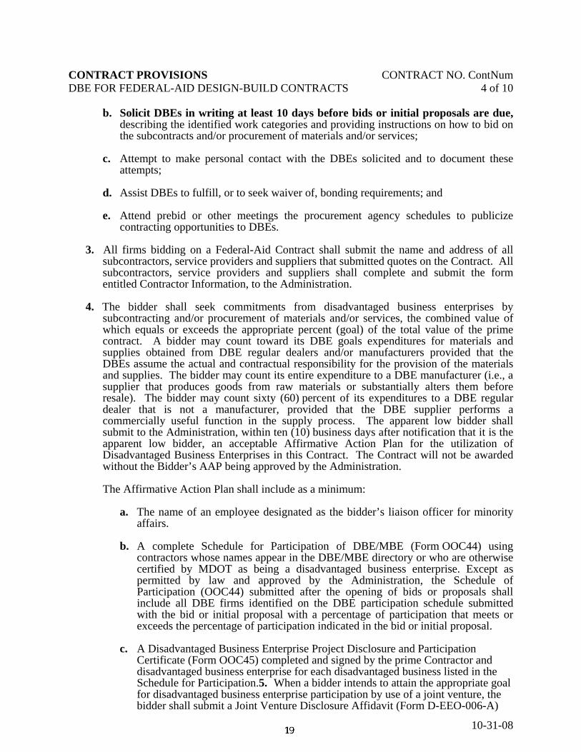
CONTRACT PROVISIONS CONTRACT NO. ContNum DBE FOR FEDERAL-AID DESIGN-BUILD CONTRACTS 4 of 10
10-31-08
b. Solicit DBEs in writing at least 10 days before bids or initial proposals are due, describing the identified work categories and providing instructions on how to bid on the subcontracts and/or procurement of materials and/or services;
c. Attempt to make personal contact with the DBEs solicited and to document these
attempts; d. Assist DBEs to fulfill, or to seek waiver of, bonding requirements; and e. Attend prebid or other meetings the procurement agency schedules to publicize
contracting opportunities to DBEs. 3. All firms bidding on a Federal-Aid Contract shall submit the name and address of all
subcontractors, service providers and suppliers that submitted quotes on the Contract. All subcontractors, service providers and suppliers shall complete and submit the form entitled Contractor Information, to the Administration.
4. The bidder shall seek commitments from disadvantaged business enterprises by subcontracting and/or procurement of materials and/or services, the combined value of which equals or exceeds the appropriate percent (goal) of the total value of the prime contract. A bidder may count toward its DBE goals expenditures for materials and supplies obtained from DBE regular dealers and/or manufacturers provided that the DBEs assume the actual and contractual responsibility for the provision of the materials and supplies. The bidder may count its entire expenditure to a DBE manufacturer (i.e., a supplier that produces goods from raw materials or substantially alters them before resale). The bidder may count sixty (60) percent of its expenditures to a DBE regular dealer that is not a manufacturer, provided that the DBE supplier performs a commercially useful function in the supply process. The apparent low bidder shall submit to the Administration, within ten (10) business days after notification that it is the apparent low bidder, an acceptable Affirmative Action Plan for the utilization of Disadvantaged Business Enterprises in this Contract. The Contract will not be awarded without the Bidder’s AAP being approved by the Administration. The Affirmative Action Plan shall include as a minimum:
a. The name of an employee designated as the bidder’s liaison officer for minority affairs.
b. A complete Schedule for Participation of DBE/MBE (Form OOC44) using
contractors whose names appear in the DBE/MBE directory or who are otherwise certified by MDOT as being a disadvantaged business enterprise. Except as permitted by law and approved by the Administration, the Schedule of Participation (OOC44) submitted after the opening of bids or proposals shall include all DBE firms identified on the DBE participation schedule submitted with the bid or initial proposal with a percentage of participation that meets or exceeds the percentage of participation indicated in the bid or initial proposal.
c. A Disadvantaged Business Enterprise Project Disclosure and Participation
Certificate (Form OOC45) completed and signed by the prime Contractor and disadvantaged business enterprise for each disadvantaged business listed in the Schedule for Participation.5. When a bidder intends to attain the appropriate goal for disadvantaged business enterprise participation by use of a joint venture, the bidder shall submit a Joint Venture Disclosure Affidavit (Form D-EEO-006-A)

CONTRACT PROVISIONS CONTRACT NO. ContNum DBE FOR FEDERAL-AID DESIGN-BUILD CONTRACTS 5 of 10
10-31-08
showing the extent of disadvantaged business participation. If a bidder intends to use a joint venture as a subcontractor to meet its goal, the affidavit shall be submitted through the bidder by the proposed subcontractor and be signed by all parties. A DBE, even in a joint venture arrangement shall be certified as a DBE by MDOT prior to being included in the Affirmative Action Plan.
6. Where the proposed DBE participation does not meet the DBE contract goals, sufficient
evidence to demonstrate that the bidder has taken all necessary and reasonable steps to make a good faith effort to meet these goals shall be required.
7. Determination of Bid Responsiveness for Federal-Aid Contracts:
If the bidder is unable to secure from DBEs by subcontracting and/or by procurement of materials and/or services, commitments which at least equal the appropriate percent (goal) of the values of the prime Contract at the time of bid, he shall request, in writing, a waiver of the unmet portion of the goal. This request must be initiated by checking the appropriate box on the DBE/MBE utilization affidavit submitted with the bid or initial proposal. The waiver may be granted by the Administrator. To obtain approval of a waiver, the bidder shall submit the following information:
a. A detailed statement of efforts made prior to bid to contact and negotiate with DBEs including: (i) the dates, names, addresses, and telephone numbers of DBEs who were contacted; (ii) a description of the information provided to DBEs requesting the plans, specifications, and anticipated time schedule for portions of the work to be performed and (iii) a detailed statement of the reasons why additional prospective agreements with DBEs were not reached;
b. A detailed statement of the efforts made to select portions of the work proposed to
be performed by DBEs in order to increase the likelihood of achieving the stated goals;
c. For each DBE that the Contractor considers not qualified, but from which a bid
has been received, a detailed statement of the reasons for the bidder’s conclusion; and
d. For each DBE contacted but unavailable, (i) a Minority Contractor Unavailability Certificate (Form OOC46) signed by the disadvantaged business enterprise, or (ii) a statement from the bidder shall be submitted that states that the DBE refused to sign the Certificate.
8. Guidance concerning good faith efforts. The following is a list of the types of actions
and factors that will be used to determine the bidder's or offeror’s good faith efforts to obtain DBE participation. It is not intended to be a mandatory checklist, nor is it intended to be exclusive or exhaustive. Other factors or types of efforts may be relevant in appropriate cases.
(1) Soliciting through all reasonable and available means (e.g. attendance at pre-bid
meetings, advertising and/or written notices) the interest of certified DBEs who have the capability to perform the work of the contract. The bidder must solicit this interest within sufficient time to allow the DBEs to respond to the solicitation.

CONTRACT PROVISIONS CONTRACT NO. ContNum DBE FOR FEDERAL-AID DESIGN-BUILD CONTRACTS 6 of 10
10-31-08
The bidder must determine with certainty if the DBEs are interested by taking appropriate steps to follow up initial solicitations.
(2) Selecting portions of the work to be performed by DBEs in order to increase the
likelihood that the DBE goals will be achieved. This includes, where appropriate, breaking out contract work items into economically feasible units to facilitate DBE participation, even when the bidder or offeror might otherwise prefer to perform these work items with its own forces.
(3) Providing interested DBEs with adequate information about the plans,
specifications, and requirements of the contract in a timely manner to assist them in responding to a solicitation.
(4) (a) Negotiating in good faith with interested DBEs. It is the bidder's or offeror’s
responsibility to make a portion of the work available to DBE subcontractors and suppliers and to select those portions of the work or material needs consistent with the available DBE subcontractors and suppliers, so as to facilitate DBE participation. (b) A bidder using good business judgment would consider a number of factors in negotiating with subcontractors, including DBE subcontractors, and would take a firm's price and capabilities as well as contract goals into consideration. However, the fact that there may be some additional costs involved in finding and using DBEs is not in itself sufficient reason for a bidder's failure to meet the contract DBE goal, as long as such costs are reasonable. Also, the ability or desire of a prime contractor to perform the work of a contract with its own organization does not relieve the bidder of the responsibility to make good faith efforts. Bidders and offerors are not, however, required to accept higher quotes from DBEs if the price difference is excessive or unreasonable.
(5) Not rejecting DBEs as being unqualified without sound reasons based on a
thorough investigation of their capabilities. The contractor's standing within its industry, membership in specific groups, organizations, or associations and political or social affiliations (for example union vs. non-union employee status) are not legitimate causes for the rejection or non-solicitation of bids in the contractor's efforts to meet the project goal.
(6) Making efforts to assist interested DBEs in obtaining bonding, lines of credit, or
insurance as required by the recipient or contractor. (7) Making efforts to assist interested DBEs in obtaining necessary equipment,
supplies, materials, or related assistance or services. (8) Effectively using the services of available minority/women community
organizations; minority/women contractors' groups; local, state, and Federal minority/women business assistance offices; and other organizations as allowed on a case-by-case basis to provide assistance in the recruitment and placement of

CONTRACT PROVISIONS CONTRACT NO. ContNum DBE FOR FEDERAL-AID DESIGN-BUILD CONTRACTS 7 of 10
10-31-08
DBEs. (9) In determining whether a bidder or offeror has made good faith efforts, you may
take into account the performance of other bidders or offerors in meeting the contract goal. For example, when the apparent successful bidder or offeror fails to meet the contract goal, but others meet it, the Administration may reasonably raise the question of whether, with additional reasonable efforts, the apparent successful bidder or offeror could have met the goal. If the apparent successful bidder or offeror fails to meet the goal, but meets or exceeds the average DBE participation obtained by other bidders or offerors, the Administration may view this, in conjunction with other factors, as evidence of the apparent successful bidder or offeror having made good faith efforts.
9. Bidder Use of MBE Special Services
The bidder shall consider, whenever possible, utilizing the services of minority-owned banks. Most minority banks are full-service corporations that can provide an array of financial services such as Treasury and Tax Loan fund accounts, time and demand deposit accounts, payroll services, and if needed, organization investment counseling.
10. Bidder Records
The bidder shall maintain records showing actions which have been taken to comply with procedures set forth herein.
11. Bidder Cooperation
The bidder shall cooperate with the Administration Representative in any reviews of the Contractor’s procedures and practices with respect to DBEs which the Administration Representative may from time to time conduct.
12. Bidder MBE Modifications During the life of the Contract, all plans to modify the approved DBE participation program will require the approval of the Administrator or his authorized representative. This shall include any changes to the items of work to be sublet or materials and services to be obtained which differ for those in the original DBE participation program. Any such request for revisions shall be directed to the appropriate District Engineer for their disposition.
C. RECORDS AND REPORTS
1. The Contractor shall keep such records as are necessary to determine compliance with its
Minority Business Enterprise utilization obligations. The records kept by the Contractor shall be designed to indicate:
a. The name of disadvantaged and non-disadvantaged subcontractors and suppliers, the
type of work materials or services being performed on or incorporated in this project, and the monetary value of such work materials or services.
b. Documentation of all correspondence, contacts, telephone calls, etc., to obtain the
services of disadvantaged business enterprises on this project.

CONTRACT PROVISIONS CONTRACT NO. ContNum DBE FOR FEDERAL-AID DESIGN-BUILD CONTRACTS 8 of 10
10-31-08
c. The progress and efforts made in seeking out disadvantaged contractor organizations
and individual disadvantaged contractors for work on this project. 2. Information required to be submitted for Federally Assisted contracts in accordance with
49 CFR Part 26:
a. All bidders (not only the apparent successful bidder) shall provide the following information:
(1) The age of the bidding firm; and (2) The annual gross receipts of the bidding firm.
b. All bidders (not only the apparent successful bidder) shall provide the following
information for each firm quoting or considered as subcontractors:
(1) The name of firm; and (2) The address of firm.
c. The Administration will contact each of the firms quoting or considered as
subcontractors to obtain:
(1) The age of the firm; and (2) The annual gross receipts of the firm
If this information already has been gathered by the Administration on a firm and it is current, it will not be requested.
3. The Contractor shall submit reports on a quarterly basis of those contracts and other
business transactions executed with disadvantaged business enterprises with respect to the records referred to in Subparagraph 1.a above, in such form, manner, and content as prescribed by the Administration. The quarterly reports shall be due on the 15th calendar day of January, April, July, and October. If the Contractor cannot submit their report on time, they shall notify the Administration’s Representative and request additional time to submit the report. Failure of the Contractor to report in a timely manner may result in a finding of non-compliance. Additional reports may be required by the Administration upon written request.
4. To ensure compliance with the certified DBE contract participation goals, the Contractor shall:
a. Submit monthly, a report listing unpaid invoices, over 30 days, from all certified DBE
subcontractors and the reason payment has not been made;
b. Include in its agreement with certified DBE subcontractors a requirement that the DBE subcontractors are to submit monthly to the Administration, a report identifying the prime Contractor and listing the following:
1. Payment received from the Contractor in the preceding 30 days; and 2. Invoices for which the subcontractor has not been paid.

CONTRACT PROVISIONS CONTRACT NO. ContNum DBE FOR FEDERAL-AID DESIGN-BUILD CONTRACTS 9 of 10
10-31-08
5. All such records shall be retained for a period of three years following acceptance of final
payment and shall be available for inspection by the U.S. Department of Transportation, the Maryland Department of Transportation, and the Administration.
D. ADMINISTRATIVE PROCEDURES FOR ENFORCEMENT
1. Whenever the Administration believes the prime Contractor or any subcontractor may not be operating in compliance with the terms of these provisions, the Administration Representative will conduct an investigation. If the Administration Representative finds the prime Contractor or any subcontractor not in compliance with these provisions, he will make a report of non-compliance and notify such Contractor in writing of the steps that will, in the judgment of the Administration, bring the Contractor into compliance. If the Contractor fails or refuses to comply fully with such steps, the Administration Representative will make a final report of noncompliance to the Administrator, who may direct the imposition of one or more of the sanctions listed below:
a. Suspension of work on a project, pending correction; b. Withholding payment or a percentage thereof, pending correction; c. Referral of DBE/MBE to MDOT Office of MBE for review for decertification or
minority business fraud investigation; d. Referral to MDOT Office of MBE for review/referral to the Attorney General’s
Office for review for initiation of debarment; e. Referral to the Attorney General’s Office for review for debarment or for criminal
prosecution through the MDOT Office of General Counsel; or
f. Any other action as appropriate.
The Administrator will determine which sanction(s) should be imposed in order to promote the purpose of the MDOT DBE/MBE Program.
2. If the documents used to determine the status of a DBE contain false, misleading, or
misrepresenting information, the matter may be referred to the MDOT Office of MBE for appropriate action.
3. Loss of DBE Certification
a. When a prime Contractor has made a commitment to use a DBE who has lost its
certification but the subcontract has not been executed prior to the notice of loss of certification, the prime Contractor is required to obtain an eligible, certified DBE for the contract or demonstrate to MDOT that it has made a good faith effort to do so.
b. When a prime Contractor has executed a contract with a DBE subcontractor before
the notice of loss of certification, the prime Contractor may continue to use the firm on the contract and may continue to receive credit towards its DBE goal, i.e., contract goal, for the work of that subcontractor.

CONTRACT PROVISIONS CONTRACT NO. ContNum DBE FOR FEDERAL-AID DESIGN-BUILD CONTRACTS 10 of 10
10-31-08
c. The work carried out by a DBE Prime Contractor would be counted by MDOT up to the loss of certification. The work performed after the loss of certification would not be considered DBE participation.
d. When a DBE subcontractor has lost its certification, MDOT may not continue to
count the DBE participation which takes place after the loss of certification as DBE work when counting participation towards the overall goal of the modal administration or the Department.
e. If a DBEs loss of certification is the result of exceeding the size standards while
performing on a contract, the DBE participation may be counted for both the contract goal and the overall goal.

CONTRACT PROVISIONS CONTRACT NO. ContNum NOTICE TO CONTRACTORS MBE/DBE GOAL 1 of 1
12-03-09
NOTICE TO CONTRACTORS CONCERNING THE MBE/DBE GOAL ON THIS CONTRACT
The Maryland Department of Transportation is committed to providing the maximum amount of contracting opportunities to certified Minority Business Enterprises (MBEs) and Disadvantaged Business Enterprises (DBEs). The previously established policy excluded consideration of the cost of supplying structural steel for MBE/DBE participation since there were no structural steel manufacturers certified by MDOT. This exemption is no longer applicable since MBE/ DBE firms have been certified under this category. The Administration reserves the right to verify the accuracy of the dollar value included on the Contractor’s Affirmative Action Plan, including the value associated with the manufacture, supply, and installation of structural steel.

CONTRACT PROVISIONS CONTRACT NO. HA2705171 MBE/DBE COMPLIANCE FIELD MEETING 1 of 1
10-31-08
MBE/DBE COMPLIANCE FIELD MEETING
A MBE/DBE compliance Field Meeting will be conducted to review the responsibilities of the Administration and the Contractor’s personnel relative to MBE/DBE Compliance and documentation. The meeting will be held within two weeks after starting work on the project. The Construction Project Engineer, who will notify the following of the date, time and location, will arrange the meeting. At least one week advanced notice will be required. (a) Administrative Representatives. (1) Director, Office of Equal Opportunity or Designee (2) District Equal Opportunity Officer (3) Regional Constructional Engineer (4) Construction Project Engineer (5) Construction Inspection Division Inspector (b) Contract Representatives. (1) Superintendent - Prime Contractor (2) Equal Opportunity Officer - Prime Contractor (3) Owner/Superintendent/Foreman MBE/ DBE - Subcontractor The Construction Project Engineer and Equal Opportunity Representative will jointly conduct the meeting. The Contractor shall notify the appropriate subcontractors and ensure their attendance.

CONTRACT PROVISIONS CONTRACT NO. ContNum TRAFFIC CONTROL PLAN CERTIFICATION FAP NO. Pending 1 of 1
6/22/08
TRAFFIC CONTROL PLAN CERTIFICATION FOR DESIGN-BUILD PRIOR TO THE COMMENCEMENT OF WORK ON THIS PROJECT, THE SUCCESSFUL BIDDER WILL BE REQUIRED TO COMPLETE A TRAFFIC CONTROL PLAN CERTIFICATION, CONTAINING THE INFORMATION SHOWN BELOW. THE CERTIFICATION FORM WILL BE PROVIDED TO THE SUCCESSFUL BIDDER UPON AWARD OF THE CONTRACT. The Administration's Traffic Control Plan (TCP) has been reviewed and the following course of action shall be followed: Option 1 See Note Below The TCP is accepted and shall be used on this project. Option 2 See Note Below The TCP is accepted; however, revisions and/or additions shall be submitted for approval
in conformance with the Administration's Specifications 104.01. Option 3 The TCP is not accepted and revision shall be submitted for approval in accordance with
the Administration's Specifications 104.01. It is understood that the effective implementation of the approved TCP is the responsibility of the Contractor. Minor modifications may be made by the Traffic Manager if field conditions warrant and prior concurrence is obtained from the Engineer. Significant changes to the TCP will be submitted to the Engineer in writing, for approval, in conformance with the Administration's Specifications 104.01. (DATE) (SIGNATURE) (PRINT SIGNATURE) (TITLE) Note: Option 1 and 2 shall not be used on this project.
This is a Design-build project and the Design-Build Team must prepare a TCP based on the requirements in the Administrations Specifications 104.01.

CONTRACT PROVISIONS CONTRACT NO. HA2705171 PREVAILING WAGE INSTRUCTIONS 1 of 3
10-06-09
PREVAILING WAGE INSTRUCTIONS FOR THE CONTRACTOR
PAYROLLS. Non-Federally Funded Contracts. For Non-Federally funded projects, which include prevailing wage rates, the prime Contractor and each subcontractor shall submit two copies of their payroll records. One copy shall be submitted to the Project Engineer and one shall be sent to the Maryland State Commissioner of Labor & Industry, Room 607, 1100 N. Eutaw Street, Baltimore, MD 21201, where they will be available for inspection during business hours. All wages shall be paid in conformance with the State Finance and Procurement Article, Section 17-201-17-226 of the Annotated Code of Maryland and the Fair Labor Standards Amendments of 1974 (P.L. 93259). If the award amount of a Non-Federally funded job is less than $500,000, the project will be exempt from prevailing wage requirements. A review has been made of the wage conditions in the locality and, based on the information available, the wage rates and fringe payments listed are determined by the Commissioner of the Department of Labor and Industry to be prevailing for the Contract for the described classes of labor in conformance with the law. It shall be the responsibility of the Contractor to fully comply with the law and to contact the Office of the Commissioner of Labor and Industry for interpretation of the provisions of the law. Federally Funded Contracts. For Federally funded projects, the prime Contractor and each subcontractor shall submit one copy of the certified payroll to the Project Engineer. General Requirements for Federally and Non-Federally Funded Contracts. All payrolls are subject to the following requirements: (a) All payrolls shall be numbered, beginning at No. 1, and consecutively numbered through
the end of the Contract. (b) Contract and FAP numbers shall be shown on all payrolls (as applicable). (c) All payroll submissions shall include the employees’ full name, classification, and a unique
employee identification number.
NOTE: Employees’ address and social security number are no longer required. Update revisions to FHWA 1273 and US DOL Form WH-347 are pending.
(d) All payrolls shall show the employee’s basic hourly wage rate, overtime rate (if
applicable), and the number of hours worked (tabulated both daily and weekly).

CONTRACT PROVISIONS CONTRACT NO. HA2705171 PREVAILING WAGE INSTRUCTIONS 2 of 3
10-06-09
(e) When fringe benefits are required, indicate separately the amount of employer contributions to fringe benefit funds and/or programs. The fringe benefits shall be individually identified, but may be tabulated on a separate sheet. When required fringe benefits are paid in cash, add the required fringe benefit amount to the basic hourly rate to obtain the total prevailing wage rate for the employee.
(f) The employee’s net pay and the itemized deductions shall be included in all payrolls.
(g) A Contractor may make deductions that are required by law or required by a collective
bargaining agreement (between the Contractor and a bona fide labor organization). Deductions are also permitted if they are identified in a written agreement between the employee and employer that was made at the beginning of employment, provided that the Contractor presents the agreement to the Administration before the employee begins working on the Contract. Each payroll shall also include the U.S. Department of Labor and Hour Public Contracts Division Statement of Compliance Form WH-347 (or its equivalent), signed by an appropriate official of the Contractor/subcontractor. The Contractor’s name, address, and telephone number shall also to be shown.
(h) On Non-Federally funded projects, all apprentices shall be registered with the Maryland
Apprenticeship and Training Council. (i) Contractors employing a classification of worker for which a wage rate was not included
on the original wage decision, shall submit to the Wage and Hour Team, a request for an additional classification and rate prior to the employee’s employment at the project.
(j) Payrolls for Non-Federally Funded projects shall be submitted within 14 calendar days
after the end of each payroll period. (k) Payrolls for Federally Funded projects shall be submitted within 7 calendar days after the
end of each payroll period.
(l) Payroll submissions shall no longer contain an employee’s home address or complete social security number. Contractors and Subcontractors are required to maintain complete social security numbers and home addresses for employees. Government agencies are entitled to request or review all relevant payroll information, including social security numbers and addresses of employees. Contractors and Subcontractors are required to provide such information upon request.
OVERTIME. Non-Federally Funded Contracts. Overtime rates shall be paid by the prime Contractors and subcontractors under their Contracts and agreements with their employees, which in no event shall be less than time and a half the prevailing hourly rate of wages for all hours worked in excess of ten hours in any one calendar day or forty hours in any one calendar week and work performed on Sundays and legal holidays.

CONTRACT PROVISIONS CONTRACT NO. HA2705171 PREVAILING WAGE INSTRUCTIONS 3 of 3
10-06-09
Fringe benefits shall be paid for all hours worked, including the overtime hours. However, the fringe benefit amounts may be excluded from the half time premium due as overtime compensation. Federally Funded Contracts. Overtime rates shall be paid as specified in Form FHWA 1273. Fringe benefits shall be paid for all hours worked, including the overtime hours. However, the fringe benefit amounts may be excluded from the half time premium due as overtime compensation. PENALTIES. Non-Federally Funded Contracts. When the Contractor is delinquent in submitting payroll records, processing of partial payment estimates will be held in abeyance, pending receipt of the records. The Contractor shall be liable to the Administration for liquidated damages in the amount of $10.00 for each calendar day the records are late. The Contractor shall be liable to the Administration for liquidated damages in the amount of $20.00 for each day that an employee is paid less than the prevailing wage. Federally Funded Contracts. When the Contractor is delinquent in submitting payroll records, processing of partial payment estimates will be held in abeyance pending receipt of the records. ADDITIONAL CLASSIFICATIONS.
If the wage determination lacks a necessary classification the Prime Contractor is responsible to submit the request for the additional classification, with a proposed rate, to the State Highway Administration’s Wage and Hour Team. The request is to include a copy of the projects wage determination. INQUIRIES. Requests for information or questions shall be addressed to:
Maryland State Highway Administration Design Technical Services Division Wage and Hour Team 707 N. Calvert Streets, MS C-102 Baltimore, MD 21203-0717 Telephone: 410-545-8795 Fax: 410-209-5001

GENERAL DECISION: MD20100071 03/12/2010 MD71 Date: March 12, 2010 General Decision Number: MD20100071 03/12/2010 Superseded General Decision Number: MD20080071 State: Maryland Construction Type: Highway County: Harford County in Maryland. HIGHWAY CONSTRUCTION PROJECTS (excluding tunnels, building structures in rest area projects & railroad construction; bascule, suspension & spandrel arch bridges designed for commercial navigation, bridges involving marine construction; and other major bridges). Modification Number Publication Date 0 03/12/2010 SUMD2010-013 01/28/2010 Rates Fringes BLASTER..........................$ 16.16 4.73 BRICKLAYER Bricklayer..................$ 26.81 7.82 Caulker.....................$ 26.81 7.82 Rigger......................$ 26.81 7.82 Sawman......................$ 26.81 7.82 CARPENTER Carpenter...................$ 24.09 9.62 Caulker.....................$ 24.09 9.62 Drywall.....................$ 23.86 9.52 Rigger......................$ 23.87 9.62 CEMENT MASON/CONCRETE FINISHER Caulker.....................$ 23.30 8.11 Cement Mason/Concrete Finisher....................$ 23.30 8.11 Rigger......................$ 23.30 8.11 ELECTRICIAN Caulker.....................$ 32.90 13.88 Electrician.................$ 32.90 13.88 Rigger......................$ 32.90 13.88 Street Lighting.............$ 32.90 13.88 FIREPROOFER
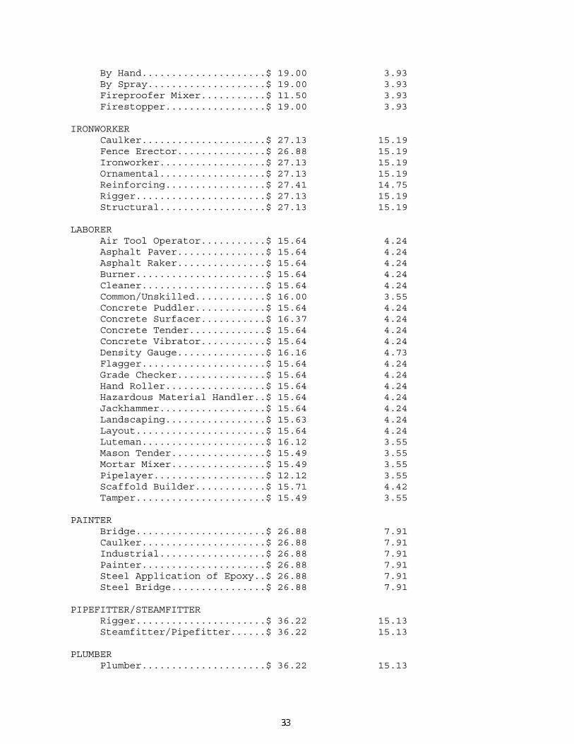
By Hand.....................$ 19.00 3.93 By Spray....................$ 19.00 3.93 Fireproofer Mixer...........$ 11.50 3.93 Firestopper.................$ 19.00 3.93 IRONWORKER Caulker.....................$ 27.13 15.19 Fence Erector...............$ 26.88 15.19 Ironworker..................$ 27.13 15.19 Ornamental..................$ 27.13 15.19 Reinforcing.................$ 27.41 14.75 Rigger......................$ 27.13 15.19 Structural..................$ 27.13 15.19 LABORER Air Tool Operator...........$ 15.64 4.24 Asphalt Paver...............$ 15.64 4.24 Asphalt Raker...............$ 15.64 4.24 Burner......................$ 15.64 4.24 Cleaner.....................$ 15.64 4.24 Common/Unskilled............$ 16.00 3.55 Concrete Puddler............$ 15.64 4.24 Concrete Surfacer...........$ 16.37 4.24 Concrete Tender.............$ 15.64 4.24 Concrete Vibrator...........$ 15.64 4.24 Density Gauge...............$ 16.16 4.73 Flagger.....................$ 15.64 4.24 Grade Checker...............$ 15.64 4.24 Hand Roller.................$ 15.64 4.24 Hazardous Material Handler..$ 15.64 4.24 Jackhammer..................$ 15.64 4.24 Landscaping.................$ 15.63 4.24 Layout......................$ 15.64 4.24 Luteman.....................$ 16.12 3.55 Mason Tender................$ 15.49 3.55 Mortar Mixer................$ 15.49 3.55 Pipelayer...................$ 12.12 3.55 Scaffold Builder............$ 15.71 4.42 Tamper......................$ 15.49 3.55 PAINTER Bridge......................$ 26.88 7.91 Caulker.....................$ 26.88 7.91 Industrial..................$ 26.88 7.91 Painter.....................$ 26.88 7.91 Steel Application of Epoxy..$ 26.88 7.91 Steel Bridge................$ 26.88 7.91 PIPEFITTER/STEAMFITTER Rigger......................$ 36.22 15.13 Steamfitter/Pipefitter......$ 36.22 15.13 PLUMBER Plumber.....................$ 36.22 15.13

Rigger......................$ 36.22 15.13 POWER EQUIPMENT OPERATOR: Asphalt Distributor.........$ 21.19 9.93 Backhoe.....................$ 23.24 8.29+a Bobcat......................$ 21.19 9.93+a Boom Truck..................$ 21.19 9.93 Broom Truck.................$ 21.19 9.93+a Bulldozer...................$ 23.85 11.05 Concrete Pump...............$ 23.85 11.05 Crane, Tower................$ 26.60 11.05+a Crane.......................$ 25.81 10.31+a Drill Rig...................$ 24.10 11.05 Driller.....................$ 24.10 11.05 Excavator...................$ 23.41 10.10+a Forklift....................$ 23.41 10.10 Gradall.....................$ 24.10 10.23+a Grader......................$ 23.85 8.29+a Hoist.......................$ 16.16 4.73 Loader......................$ 23.41 10.10+a Marine: Boat Captain...............$ 24.10 11.05 Crew Boat Operator.........$ 24.10 11.05 Tug Deckhand...............$ 24.10 11.05 Master Mechanic Rigger......$ 23.41 10.10 Master Mechanic.............$ 23.41 10.10 Milling Machine.............$ 23.41 10.10+a Oiler.......................$ 23.41 10.10 Paver.......................$ 23.41 10.10 Pettibone...................$ 23.41 10.10 Piledriver..................$ 24.09 10.02 Rigger......................$ 23.71 10.76 Roller, Asphalt.............$ 24.56 10.51 Roller, Earth...............$ 23.41 10.10+a Scraper Pan.................$ 21.75 8.61+a Scraper.....................$ 21.75 8.61+a Screed......................$ 21.75 8.61 Shoulder Machine............$ 21.75 8.61 Skidder.....................$ 21.75 8.61 Spreader....................$ 21.75 8.61 Sweeper.....................$ 21.75 8.61+a Track Drill.................$ 21.75 8.61 Tractor with attachments....$ 19.89 8.81 Trencher....................$ 21.75 8.61 Trimmer.....................$ 21.75 8.61 SHEET METAL WORKER...............$ 23.17 8.78 SPRINKLER FITTER.................$ 29.95 15.80 TRUCK DRIVER A Frame.....................$ 19.89 8.81 Concrete Pump...............$ 19.89 8.81 Dump, Articulating..........$ 19.89 8.81

Dump........................$ 19.89 8.81 Flatbed.....................$ 19.89 8.81 Lowboy......................$ 19.89 8.81 Tack........................$ 19.89 8.81 Tandem......................$ 19.89 8.81 Tar.........................$ 19.89 8.81 Tractor Trailer.............$ 19.89 8.81 Water.......................$ 19.89 8.81 FOOTNOTE: a. PAID HOLIDAYS: New Year's Day, Memorial Day, Independence Day, Labor Day, Thanksgiving Day & Christmas Day. ---------------------------------------------------------------- WELDERS - Receive rate prescribed for craft performing operation to which welding is incidental. ======================================================== Unlisted classifications needed for work not included within the scope of the classifications listed may be added after award only as provided in the labor standards contract clauses (29 CFR 5.5(a)(1)(ii)). ---------------------------------------------------------------- -- In the listing above, the "SU" designation means that rates listed under the identifier do not reflect collectively bargained wage and fringe benefit rates. Other designations indicate unions whose rates have been determined to be prevailing. ---------------------------------------------------------------- -- WAGE DETERMINATION APPEALS PROCESS 1.) Has there been an initial decision in the matter? This can be: * an existing published wage determination * a survey underlying a wage determination * a Wage and Hour Division letter setting forth a position on a wage determination matter * a conformance (additional classification and rate) ruling On survey related matters, initial contact, including requests for summaries
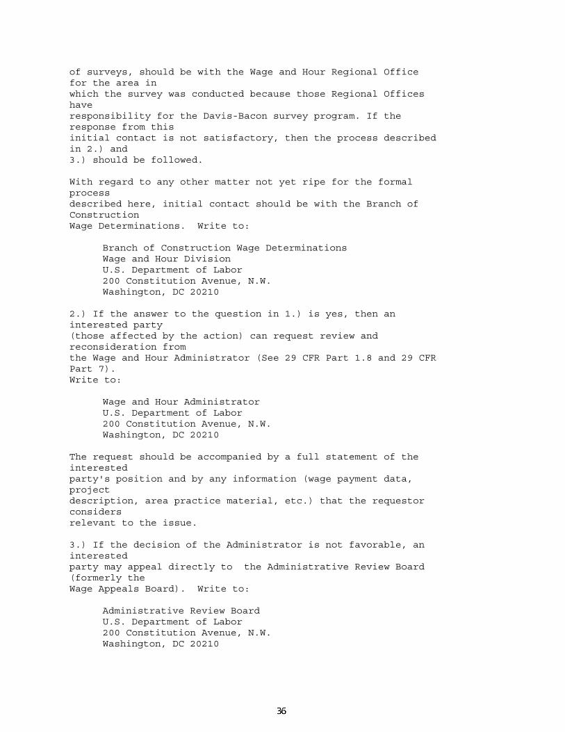
of surveys, should be with the Wage and Hour Regional Office for the area in which the survey was conducted because those Regional Offices have responsibility for the Davis-Bacon survey program. If the response from this initial contact is not satisfactory, then the process described in 2.) and 3.) should be followed. With regard to any other matter not yet ripe for the formal process described here, initial contact should be with the Branch of Construction Wage Determinations. Write to: Branch of Construction Wage Determinations Wage and Hour Division U.S. Department of Labor 200 Constitution Avenue, N.W. Washington, DC 20210 2.) If the answer to the question in 1.) is yes, then an interested party (those affected by the action) can request review and reconsideration from the Wage and Hour Administrator (See 29 CFR Part 1.8 and 29 CFR Part 7). Write to: Wage and Hour Administrator U.S. Department of Labor 200 Constitution Avenue, N.W. Washington, DC 20210 The request should be accompanied by a full statement of the interested party's position and by any information (wage payment data, project description, area practice material, etc.) that the requestor considers relevant to the issue. 3.) If the decision of the Administrator is not favorable, an interested party may appeal directly to the Administrative Review Board (formerly the Wage Appeals Board). Write to: Administrative Review Board U.S. Department of Labor 200 Constitution Avenue, N.W. Washington, DC 20210

4.) All decisions by the Administrative Review Board are final. END OF GENERAL DECISION

CONTRACT PROVISIONS CONTRACT NO. HA2705171 NOTICE OF ACTIONS FOR AFFIRMATIVE ACTION 1 of 8
10-31-08
NOTICE OF ACTIONS REQUIRED FOR AFFIRMATIVE ACTION TO ENSURE EQUAL EMPLOYMENT OPPORTUNITY (EXECUTIVE ORDER 11246)
1. The Offeror's or Bidders attention is called to the "Equal Opportunity Clause" and the "Standard
Federal Equal Employment Specifications" set forth herein. 2. The goals and timetables for minority and female participation, expressed in percentage terms
for the Contractor's aggregate work force in each trade on all construction work in the covered area, are as noted in Appendix A and B:
These goals are applicable to all the Contractors' construction work (whether or not it is Federal
or federally assisted) performed in the covered area. If the contractor performs construction work in a geographical area located outside of the covered area, it shall apply the goals established for such geographical area where the work is actually performed. With regard to this second area, the contractor also is subject to the goals for both its federally involved and nonfederally involved construction.
The contractor's compliance with the Executive Order and the regulations in 41 CFR Part 60-4
shall be based on its implementation of the Equal Opportunity Clause, specific affirmative action obligations required by the specifications set forth in 41 CFR 60-4.3(a), and its efforts to meet the goals. The hours of minority and female employment and training must be substantially uniform throughout the length of contract, and in each trade, and the contractor shall make a good faith effort to employ minorities and women evenly on each of its projects. The transfer of minority or female employees or trainees from Contractor to Contractor or from project to project for the sole purpose of meeting the contractor's goals shall be a violation of the contract, the Executive Order and the regulations in 41 CFR Part 60-4. Compliance with the goals will be measured against the total work hours performed.
3. The Contractor shall provide written notification to the Director of the Office of Federal
Contract Compliance Programs within 10 working days of award of any construction subcontract in excess of $10,000 at any tier for construction work under the contract resulting from this notification. The notification shall list the name, address, and telephone number of the subcontractor; employer identification number of the subcontractor; estimated dollar amount of the subcontract; estimated starting and completion dates of the subcontract; and the geographical area in which the subcontract is to be performed.
4. As used in this Notice, and in the contract resulting from this solicitation, the "covered area" is
noted on appendix B.
STANDARD FEDERAL EQUAL EMPLOYMENT OPPORTUNITY CONSTRUCTION CONTRACT SPECIFICATIONS (Executive Order 11246)
1. As used in these specifications: a. "Covered area" means the geographical area described in the solicitation from which this
contract resulted; b. "Director" means Director, Office of Federal Contract Compliance Programs, United States
Department of Labor, or any person to whom the Director delegates authority;

CONTRACT PROVISIONS CONTRACT NO. HA2705171 NOTICE OF ACTIONS FOR AFFIRMATIVE ACTION 2 of 8
10-31-08
c. "Employer identification number" means the Federal Social Security number used on the Employer's Quarterly Federal Tax Return, U.S. Treasury Department Form 941.
d. "Minority" includes: (i) Black (all persons having origins in any of the Black African racial groups not of
Hispanic origin); (ii) Hispanic (all persons of Mexican, Puerto Rican, Cuban, Central or South American or
other Spanish culture or origin regardless of race); (iii) Asian and Pacific Islander (all persons having origins in any of the original people of
the Far East, Southeast Asia, the Indian Subcontinent, or the Pacific Islands); and, (iv) American Indians or Alaskan Native (all persons having origins in any of the original
peoples of North America and maintaining identifiable tribal affiliations through membership and participation or community identification).
2. Whenever the Contractor, or any Subcontractor at any tier, subcontracts a portion of the work
involving any construction trade, it shall physically include in each subcontract in excess of $10,000 the provisions of these specifications and the Notice which contains the applicable goals for minority and female participation and which is set forth in the solicitations from which this contract resulted.
3. If the Contractor is participating (pursuant to 41 CFR 60-4.5) in a Hometown Plan approved by
the U.S. Department of Labor in the covered area either individually or through an association, its affirmative action obligations on all work in the Plan area (including goals and timetables) shall be in accordance with that Plan for those trades which have unions participating in the Plan. Contractors must be able to demonstrate their participation in and compliance with the provisions of any such Hometown Plan. Each Contractor or Subcontractor participating in an approved Plan is individually required to comply with its obligations under the EEO clause, and to make a good faith effort to achieve each goal under the Plan in each trade in which it has employees. The overall good faith performance by other Contractors or Subcontractors toward a goal in an approved Plan does not excuse any covered Contractor's or Subcontractor's failure to take good faith efforts to achieve the Plan goals and timetables.
4. The Contractor shall implement the specific affirmative action standards provided in paragraphs
7.a through 7.p of these specifications. The goals set forth in the solicitation from which this contract resulted are expressed as percentages of the total hours of employment and training of minority and female utilization the Contractor should reasonably be able to achieve in each construction trade in which it has employees in the covered area. The Contractor is expected to make substantially uniform progress toward its goal in each craft during the period specified.
5. Neither the provisions of any collective bargaining agreement, nor the failure by a union with
whom the Contractor has a collective bargaining agreement, to refer either minorities or women shall excuse the Contractor's obligations under these specifications, Executive Order 11246, or the regulations promulgated pursuant thereto.

CONTRACT PROVISIONS CONTRACT NO. HA2705171 NOTICE OF ACTIONS FOR AFFIRMATIVE ACTION 3 of 8
10-31-08
6. In order for the nonworking training hours of apprentices and trainees to be counted in meeting the goals, such apprentices and trainees must be employed by the Contractor during the training period, and the Contractor must have made a commitment to employ the apprentices and trainees at the completion of their training, subject to the availability of employment opportunities. Trainees must be trained pursuant to training programs approved by the U.S. Department of Labor.
7. The Contractor shall take specific affirmative actions to ensure equal employment opportunity.
The evaluation of the Contractor's compliance with these specifications shall be based upon its effort to achieve maximum results from its actions. The Contractor shall document these efforts fully, and shall implement affirmative action steps at least as extensive as the following:
a. Ensure and maintain a working environment free of harassment, intimidation, and coercion
at all sites, and in all facilities at which the Contractor's employees are assigned to work. The Contractor, where possible, will assign two or more women to each construction project. The Contractor shall specifically ensure that all foremen, superintendents, and other on-site supervisory personnel are aware of and carry out the Contractor's obligation to maintain such a working environment, with specific attention to minority or female individuals working at such sites or in such facilities.
b. Establish and maintain a current list of minority and female recruitment sources, provide
written notification to minority and female recruitment sources and to community organizations when the Contractor or its unions have employment opportunities available, and maintain a record of the organizations' responses.
c. Maintain a current file of the names, addresses and telephone numbers of each minority and
female off-the-street applicant and minority or female referral from a union, a recruitment source or community organization and of what action was taken with respect to each such individual. If such individual was sent to the union hiring hall for referral and was not referred back to the Contractor by the union or, if referred, not employed by the Contractor, this shall be documented in the file with reason therefore, along with whatever additional actions the Contractor may have taken.
d. Provide immediate written notification to the Director when the union or unions with which
the Contractor has a collective bargaining agreement has not referred to the Contractor a minority person or woman sent by the Contractor, or when the Contractor has other information that the union referral process has impeded the Contractor's efforts to meet its obligations.
e. Develop on-the-job training opportunities and/or participate in training programs for the area
which expressly include minorities and women, including upgrading programs and apprenticeship and trainee programs relevant to the contractor's employment needs, especially those programs funded or approved by the Department of Labor. The Contractor shall provide notice of these programs to the sources compiled under 7.b above.
f. Disseminate the Contractor's EEO policy by providing notice of the policy to unions and
training programs and requesting their cooperation in assisting the Contractor in meeting its EEO obligations; by including it in any policy manual and collective bargaining agreement; by publicizing it in the company newspaper, annual report, etc.; by specific review of the

CONTRACT PROVISIONS CONTRACT NO. HA2705171 NOTICE OF ACTIONS FOR AFFIRMATIVE ACTION 4 of 8
10-31-08
policy with all management personnel and with all minority and female employees at least once a year and by posting the company EEO policy on bulletin boards accessible to all employees at each location where construction work is performed.
g. Review, at least annually, the company's EEO Policy and affirmative action obligations
under these specifications with all employees having any responsibility for hiring, assignment, layoff, termination or other employment decisions including specific review of these items with on-site supervisory personnel such as Superintendents, General Foremen, etc., prior to the initiation of construction work at any job site. A written record shall be made and maintained identifying the time and place of these meetings, persons attending, subject matter discussed, and disposition of the subject matter.
h. Disseminate the Contractor's EEO policy externally by including it in any advertising in the
news media, specifically including minority and female news media, and providing written notification to and discussing the Contractor's EEO policy with other Contractors and Subcontractors with whom the Contractor does or anticipates doing business.
i. Direct its recruitment efforts, both oral and written, to minority, female and community
organizations, to schools with minority and female students and to minority and female recruitment and training organizations serving the Contractor's recruitment area and employment needs. Not later than one month prior to the date for the acceptance of applications for apprenticeship or other training by any recruitment source, the Contractor shall send written notification to organizations such as the above, describing the openings, screening procedures, and tests to be used in the selection process.
j. Encourage present minority and female employees to recruit other minority persons and
women and, where reasonable, provide after school, summer and vacation employment to minority and female youth both on the site and in other areas of a Contractor's work force.
k. Validate all tests and other selection requirements where there is an obligation to do so under
41 CFR Part 60-3. l. Conduct, at least annually, an inventory and evaluation at least of all minority and female
personnel for promotional opportunities and encourage these employees to seek or to prepare for, through appropriate training, etc., such opportunities.
m. Ensure that seniority practices, job classifications, work assignments and other personnel
practices, do not have a discriminatory effect by continually monitoring all personnel and employment related activities to insure that the EEO policy and the Contractor's obligations under these specifications are being carried out.
n. Ensure that all facilities and company activities are nonsegregated except that separate or
single-user toilet and necessary changing facilities shall be provided to assure privacy between the sexes.
o. Document and maintain a record of all solicitations of offers for subcontracts from minority
and female construction contractors and suppliers, including circulation of solicitations to minority and female contractor associations and other business associations.

CONTRACT PROVISIONS CONTRACT NO. HA2705171 NOTICE OF ACTIONS FOR AFFIRMATIVE ACTION 5 of 8
10-31-08
p. Conduct a review, at least annually, of all supervisors' adherence to and performance under the Contractor's EEO policies and affirmative action obligations.
8. Contractors are encouraged to participate in voluntary associations which assist in fulfilling one
or more of their affirmative action obligations (7.a through 7.p). The efforts of a contractor association, joint contractor-union, contractor-community, or other similar group of which the contractor is a member and participant, may be asserted as fulfilling any one or more if its obligations under 7.a through 7.p of these specifications provided that the contractor actively participates in the group, makes every effort to assure that the group has a positive impact on the employment of minorities and women in the industry, ensures that the concrete benefits of the program are reflected in the Contractor's minority and female work force participation, makes a good faith effort to meet its individual goals and timetables, and can provide access to documentation which demonstrates the effectiveness of actions taken on behalf of the Contractor. The obligation to comply, however, is the Contractor's and failure of such a group to fulfill an obligation shall not be a defense for the Contractor's non-compliance.
9. A single goal for minorities and a separate single goal for women have been established. The
Contractor, however, is required to provide equal employment opportunity and to take affirmative action for all minority groups, both male and female, and all women, both minority and non-minority. Consequently, the Contractor may be in violation of the Executive Order if a particular group is employed in a substantially disparate manner (for example, even though the Contractor has achieved its goals for women generally the Contractor may be in violation of the Executive Order if a specific minority group of women is underutilized).
10. The Contractor shall not use the goals and timetables or affirmative action standards to
discriminate against any person because of race, color, religion, sex, or national origin. 11. The Contractor shall not enter into any Subcontract with any person or firm debarred from
Government contracts pursuant to Executive Order 11246. 12. The Contractor shall carry out such sanctions and penalties for violation of these specifications
and of the Equal Opportunity Clause, including suspension, termination and cancellation of existing subcontracts as may be imposed or ordered pursuant to Executive Order 11246, as amended, and its implementing regulations, by the Office of Federal Contract Compliance Programs. Any Contractor who fails to carry out such sanctions and penalties shall be in violation of these specifications and Executive Order 11246, as amended.
13. The Contractor, in fulfilling its obligations under these specifications, shall implement specific
affirmative action steps, at least as extensive as those standards prescribed in paragraph 7 of these specifications, so as to achieve maximum results from its efforts to ensure equal employment opportunity. If the Contractor fails to comply with the requirements of the Executive Order, the implementing regulations, or these specifications, the Director shall proceed in accordance with 41 CFR 60-4.8.
14. The Contractors shall designate a responsible official to monitor all employment related
activity to ensure that the company EEO policy is being carried out to submit reports relating to the provisions hereof as may be required by the Government and to keep records. Records shall at affiliation if any, employee identification number when assigned, social security number, race, sex, status (e.g., mechanic, apprentice, trainee, helper, or laborer), dates of changes in status, hours worked per week in the indicated trade, rate of pay, and locations at which the work was performed. Records shall be maintained in an easily understandable and

CONTRACT PROVISIONS CONTRACT NO. HA2705171 NOTICE OF ACTIONS FOR AFFIRMATIVE ACTION 6 of 8
10-31-08
retrievable form; however, to the degree that existing records satisfy this requirement, contractors shall not be required to maintain separate records.
15. Nothing herein provided shall be construed as a limitation upon the application of other laws
which establish different standards of compliance or upon the application of requirements for the hiring of local or other area residents
(a.g., those under the Public Works Employment Act of 1977 and the Community Development
Block Grant Program). 16. The Contractor will receive at the time of Award Federal Form CC-257 for his use in reporting
monthly the Affirmative Actions for minority and female which he has employed.

CONTRACT PROVISIONS CONTRACT NO. HA2705171 NOTICE OF ACTIONS FOR AFFIRMATIVE ACTION 7 of 8
10-31-08
APPENDIX A The following goals and timetables for female utilization shall be included in all Federal and federally assisted construction contracts and subcontracts in excess of $10,000. The goals are applicable to the Contractor's aggregate on-site construction work force whether or not part of that work force is performing on a Federal or federally assisted construction contract or subcontract. AREA COVERED: Nationwide
GOALS AND TIMETABLES Timetable Goals (percent) From April 1, 1978 until March 31, 1979.................................................. 3.1 From April 1, 1979 until March 31, 1980.................................................. 5.0 From April 1, 1980 until further notice...................................................... 6.9

CONTRACT PROVISIONS CONTRACT NO. HA2705171 NOTICE OF ACTIONS FOR AFFIRMATIVE ACTION 8 of 8
10-31-08
APPENDIX B Until further notice, the following goals for minority utilization in each construction craft and trade shall be included in all Federal or federally assisted construction contracts and subcontracts in excess of $10,000 to be performed in the respective geographical areas. The goals are applicable to each nonexempt contractor's total on-site construction work force, regardless of whether or not part of that work force is performing work on a Federal, federally assisted or nonfederally related project, contract or subcontract. Construction contractors which are participating in an approved Hometown Plan (see 41 CFR 60-4.5) are required to comply with the goals of the Hometown Plan with regard to construction work they perform in the area covered by the Hometown Plan. With regard to all their other covered construction work such contractors are required to comply with the applicable SMSA or EA goal contained in this appendix B-80. Goal State (percent) Maryland: 019 Baltimore, MD: SMSA Counties: 0720 Baltimore, MD........................................................................................... 23.0 MD Anne Arundel; MD Baltimore; MD Carroll; MD Harford; MD Howard; MD Baltimore City Non-SMSA Counties............................................................................................... 23.6 MD Caroline; MD Dorchester; MD Kent; MD Queen Annes; MD Somerset; MD Talbot; MD Wicomico; MD Worcestar Washington, DC: 020 Washington, DC: SMSA Counties: 8840 Washington, DC.......................................................................................... 28.0 MD Charles; MD Montgomery; MD Prince Georges Non-SMSA Counties............................................................................................ 25.2 MD Calvert; MD Frederick MD St. Marys; MD Washington Pennsylvania Non-SMSA Counties............................................................................................ 4.8 MD Allegany: MD Garrett

CONTRACT PROVISIONS CONTRACT NO. HA2705171 TRAINING PROVISIONS 1 of 4
10-31-08
TRAINING PROVISIONS As part of the Contract's Equal Employment Opportunity Affirmative Action Program, on-the-job training shall be provided as follows: The on-the-job training shall be aimed at developing full journeypersons in the type of trade or
job classification involved. On this Contract 4 (number to be filled in by the Administration) persons will be trained.
In the event that a Contractor subcontracts a portion of the Contract work, the Contractor shall determine how many, if any, of the trainees are to be trained by the subcontractor, however, the Contractor shall retain the primary responsibility for meeting the training requirements imposed by this Provision. The Contractor shall also insure that this training Provision is physically included in each subcontract to insure that the workforce utilized by the subcontractor meet the goals for minority and female employment and training. Where feasible, 25 percent of apprentices or trainees in each occupation shall be in their first year of apprenticeship or training. The number of trainees in each classification shall be distributed among the work classifications on the basis of the Contractor's needs, minority and women employment goals specified for each trade in the Contract Provision, and the reasonable area of recruitment. Prior to beginning construction, the Contractor shall submit to the Administration for approval a Manpower and Training Utilization (MTU) Schedule no later than at the preconstruction meeting. The MTU schedule shall include: 1. The proposed training programs. 2. The number of trainees to be trained in each classification. 3. Anticipated starting and ending dates for training in each classification. No Contract work may be undertaken until the Administration has accepted the schedule. If the submitted training programs fail to meet the requirements as defined within these Provisions, the Administration will withhold one percent of the total category code one pay items from the payment due the Contractor. The Contractor shall submit a revised Manpower and Training Utilization Schedule when major changes in the Contract work schedule occur that substantially affect the previously submitted schedule. The Contractor shall be credited for each trainee employee who is currently enrolled or becomes enrolled in an approved program and will be reimbursed for the hourly cost of the trainee as specified in the schedule of prices. Training and upgrading of minorities and women toward journeyperson status is a primary objective of this Training Provision. The purpose for this objective is to insure a pool of qualified minorities and women to replace those journeypersons who, in the natural course of events will leave the workforce. The program will also provide opportunities to the minorities and women trainees in geographic areas where shortages in minority and women journeypersons are prevalent and recognized due to the Contractor's inability to meet the Equal Employment Opportunity goals specified in this Contract.

CONTRACT PROVISIONS CONTRACT NO. HA2705171 TRAINING PROVISIONS 2 of 4
10-31-08
The training requirements of this Training Provision are not intended nor shall they be used to discriminate against any applicant for training, whether a member of a protected class or not. It is the Contractor's responsibility to demonstrate good faith efforts to ensure an adequate workforce representation of minorities and women in all job classifications on this Contract. Therefore, the Contractor shall consider the employment Contract goals set for minorities and females when enrolling trainees. The Contractor's utilization of the on-the-job training goals will be weighed when an Equal Employment Opportunity workforce compliance determination is made. The Contractor shall make every effort to enroll minority and women trainees (e.g., by conducting systematic and direct recruitment through public and private sources likely to yield minorities and women to the extent that these persons are available within a reasonable area of recruitment). No employee shall be employed as a trainee in any classification which the individual has successfully completed a training program leading to journeyperson status or has been employed as a journeyperson. This includes a person gainfully employed as a journeyperson by virtue of informal on-the-job training. The Contractor should satisfy this requirement by including appropriate questions in the employee job application or by other suitable means. Regardless of the method used, the Contractor's records shall document the findings in each case. In the case of apprentices, evidence of indentureship and registration of the approved apprenticeship program shall be included in the Contractor's records. The minimum length and type of training and rate for each classification shall be specified in the training program by the Contractor and approved by the Administration and the Federal Highway Administration. The Administration will approve any program specified in the Administration's On-The-Job Training Manual. The Administration and the Federal Highway Administration will consider other programs if it is reasonably calculated that the programs conform to the Equal Employment Opportunity obligations of the Contract and will qualify the average trainee for journeyperson status in the specified classification by the end of the training period. Apprenticeship programs registered with the U.S. Department of Labor, Bureau of Apprenticeship and Training, or with a State apprenticeship agency recognized by the Bureau, and training programs approved by, but not necessarily sponsored by the U.S. Department of Labor, Employment and Training Administration, Bureau of Apprenticeship and Training will also be acceptable, provided that the program being offered is administered in a manner consistent with the Equal Employment obligation of Federal-aid highway construction Contracts and meets the minimum requirements of this Training Provision. Some offsite training is permissible as long as the training is an integral part of an approved training program and does not comprise a significant part of the overall training. Unless otherwise specified, the Contractor will be reimbursed 80 cents per hour of training given an employee on this Contract in conformance with an approved training program. As approved by the Engineer, reimbursement will be made for training persons in excess of the number specified herein. This reimbursement will be made even though the Contractor received additional training program funds from other sources, provided that the other sources do not specifically prohibit the Contractor from receiving other reimbursement. Reimbursement for offsite training indicated above will only be made to the Contractor where the Contractor does one or more of the following and the trainees are concurrently employed on a Federal-aid project:

CONTRACT PROVISIONS CONTRACT NO. HA2705171 TRAINING PROVISIONS 3 of 4
10-31-08
1. Contributes to the cost of the training. 2. Provides the instruction to the trainee or pays the trainee's wages during the offsite training
period. No payment will be made to the Contractor if either the failure to provide the required training, or the failure to hire the trainee as a journeyperson is caused by the Contractor and evidences a lack of "good faith" on the part of the Contractor in meeting the requirements of this Training Provision. It is normally expected that a trainee will begin training on the project as soon as feasible after the start of work utilizing the skill involved and remain on the project as long as training opportunities exist in the work classification or until the program is completed. It is not required that all trainees be on board for the entire length of the Contract. A Contractor will have fulfilled their responsibilities under this Training Provision when: 1. Systematic and direct recruitment likely to yield qualified minority and women applicants is
conducted through: a. Public and private referral sources. b. Advising the existing workforce of training opportunities. c. Unions (if applicable). 2. Acceptable training has been provided to trainees enrolled in the program. 3. The number of specified trainees have completed the minimum hours required in an
approved training program. 4. Trainees completing approved programs are retained in the workforce as journeypersons. The Contractor shall pay the trainees at least 60 percent of the appropriate minimum journeyperson's hourly rate plus the full fringe benefits specified in the Contract for the first half of the training period, 75 percent for the third quarter of the training period plus full fringe benefits, and 90 percent for the last quarter of the training period plus full fringe benefits. However, in no case shall the total hourly rate be less than the U.S. Department of Labor's unskilled laborer wage rate for the project. In addition, all trainees shall be identified as such on the certified payroll. The Contractor shall furnish the trainee a copy of the approved training program in which the trainee is enrolled. The Contractor shall provide each trainee with a certificate showing the type and length of training satisfactorily completed. The Contractor shall submit a Certificate to the trainee in the following instances: 1. Certificate of Completion when a trainee completes the total number of hours required to
complete a training program. 2. Certificate of Training when a trainee does not totally complete the required program hours. The Contractor shall provide for the maintenance of records and furnish periodic reports inclusive of the Administration's Contractor's Semiannual Training Reports, documenting his performance under this Training Provision. The Semiannual Training Report is to be submitted by the 10th of the month following the reporting period (July 10 and January 10).

CONTRACT PROVISIONS CONTRACT NO. HA2705171 TRAINING PROVISIONS 4 of 4
10-31-08
If the Contractor fails to fully comply with these Training Provisions, the Administration's Representative will make a final report of non compliance to the Administrator, who may direct the imposition of one or both of the sanctions listed below: 1. Withholding a percentage of the progress payment. 2. Other action appropriate and/or within the discretion of the Administrator.

CONTRACT PROVISIONS CONTRACT NO. HA2705171 HIGH VISIBILITY SAFETY APPAREL POLICY 1 of 2
10-31-08
Maryland Department of Transportation State Highway Administration
NOTICE TO ALL HOLDERS OF THIS CONTRACT DOCUMENT
HIGH VISIBILITY SAFETY APPAREL POLICY BACKGROUND. Research indicates that high visibility garments have a significant impact on the safety of employees who work on highways and rights-of-way. In addition, high visibility garments may help to prevent injuries and accidents and to make highway workers more visible to the motoring public, which ultimately improves traffic safety. STATEMENT OF POLICY.
(a) The High Visibility Safety Apparel Policy provides a standardized apparel program. (b) The program seeks to improve the visibility of all persons who work on Administration
highways and rights-of-way. (c) All apparel shall contain the appropriate class identification label. (d) Compliance with this policy is retroactive and becomes effective immediately. All affected
employees shall receive high visibility apparel awareness training. APPLICABILITY. This policy applies to all Administration employees and all other persons who work on Administration highways and rights-of-way. All workers shall wear, at a minimum, Class 2 ANSI/ISEA 107/2004 apparel.
(a) For Administration employees, this apparel shall have a fluorescent yellow-green background material color and be the outermost garment worn.
(b) Retro-reflective material color for Administration employee apparel shall be silver or white
and be visible at a minimum distance of 1,000 feet. The retro-reflective safety apparel shall be designed to clearly recognize and differentiate the wearer from the surrounding work environment. The retro-reflective material may be contrasted by fluorescent orange background material not exceeding one and one half inches on either side of the retro-reflective material.
(c) For non-Administration employees, this apparel shall be either fluorescent orange-red or
fluorescent yellow-green background material color and be the outermost garment worn. (d) Retro-reflective material color for non-Administration employee apparel shall either be
orange, yellow, white, silver, yellow-green, or a fluorescent version of these colors, and be visible at a minimum distance of 1,000 feet. The retro-reflective safety apparel shall be designed to clearly recognize and differentiate the wearer from the surrounding work environment.

CONTRACT PROVISIONS CONTRACT NO. HA2705171 HIGH VISIBILITY SAFETY APPAREL POLICY 2 of 2
10-31-08
Maryland Department of Transportation State Highway Administration
REFERENCES.
(a) ANSI/ISEA 107/2004 standard – American National Safety Institute/International Safety Equipment Association
(b) MUTCD 2003 – Manual for Uniform Traffic Control Devices - Sections 6D.03B and 6E.02 (c) Visibility Research – The VCTR 1989 report concludes that fluorescent colors, when
compared with non-fluorescent colors, enhance the daytime conspicuity of worker clothing. DEFINITIONS.
(a) Apparel – The outermost high-visibility garment worn by employees who work on Administration highways and rights-of-way.
(b) Highways – All roads owned by the Maryland Department of Transportation and
maintained by the Administration. (c) High Visibility – The ability for workers to be distinguishable as human forms to be seen,
day and night, at distances that allow equipment operators and motorists to see, recognize, and respond.

CONTRACT PROVISIONS CONTRACT NO. Insert Here SPECIFICATIONS
1 of 3
12/03/08
SPECIFICATIONS
All work on this project shall conform to the Maryland Department of Transportation, State Highway Administration's Specifications entitled, "Standard Specifications for Construction and Materials" dated July 2008 revisions thereof, or additions thereto, and the Special Provisions included in this Invitation for Bids. In the following sections of the “Standard Specifications for Construction and Materials.” Dated July 2008, the word “Engineer” shall be taken to mean “Design-Build Engineer.” Category 100 Preliminary Section 101.03.02 ¶ 1, Line 1 Section 101.03.04 ¶ 1, Line 2 Section 104.05.04 ¶ 1, Line 6 Section 104.08.03 ¶ 5, Line 2 Section 104.11.03 ¶ 2, Line 5 Section 107.03.01 ¶ 1, Line 1 Section 107.03.01 ¶ 8, Line 1 Section 107.03.01 ¶ 9, Line 2 Section 107.03.03 ¶ 1, Line 2 Section 107.03.05 ¶ 1, Line 4, 13 Section 107.03.06 ¶ 7, Line 2 Category 200 Grading Section 201.03.04 ¶ 6, Line 2 Section 201.03.06 ¶ 1, Line 4 Section 201.03.10 ¶ 1, Line 5 Section 204.02.03 ¶ 1, Line 1 Section 205.03 ¶ 2, Line 2 Section 206.04.02 ¶ 5, Line 2 Category 300 Drainage Section 301.03 ¶ 1, Line 2 Section 303.03.06 ¶ 1, Line 2 Section 306.03.03 ¶ 1, Line 6 Section 306.03.04 ¶ 4, Line 2 Section 306.04.03 ¶ 1, Line 1 Section 309.03.07 ¶ 1, Line 2 Section 310.03.02 ¶ 1, Line 7, 8 Section 314.02.03 ¶ 1, Line 6

CONTRACT PROVISIONS CONTRACT NO. Insert Here SPECIFICATIONS
2 of 3
12/03/08
Category 400 Structures Section 402.03.04 ¶ 2, Line 2 Section 410.03.09 ¶ 1, Line 6 Section 411.03 ¶ 1, Line 1, 7 Section 411.03 ¶ 5, Line 1 Section 430.03.14 ¶ 1, Line 6 Category 500 Paving Section 507.03.05 ¶ 5, Line 2 Section 507.03.08 ¶ 1, Line 2 Section 522.03 ¶ 1, Line 2 Category 600 Shoulders Section 602.01 ¶ 1, Line 4 Section 602.03.01 ¶ 2, Line 7 Section 602.03.01 ¶ 7, Line 3 Section 602.03.01 ¶ 8, Line 3 Section 602.03.02 ¶ 2, Line 3 Section 604.01 ¶ 1, Line 3 Section 604.03.01 ¶ 2, Line 4 Section 604.03.03 ¶ 1, Line 4 Section 605.01 ¶ 1, Line 3 Section 605.03.07 ¶ 1, Line 10 Section 606.01 ¶ 1, Line 3 Section 606.03.01 ¶ 1, Line 7 Section 606.03.01 ¶ 5, Line 3 Section 607.01 ¶ 1, Line 3 Section 607.03.01 ¶ 3, Line 3 Section 608.01 ¶ 1, Line 3 Category 700 Landscaping Section 701.01 ¶ 1, Line 4 Section 701.03.01 ¶ 2, Line 3, 6 Section 704.01 ¶ 1, Line 5 Section 705.01 ¶ 1, Line 4 Section 706.01 ¶ 1, Line 4 Section 707.01 ¶ 1, Line 3 Section 708.01 ¶ 1, Line 3 Section 709.01 ¶ 1, Line 3

CONTRACT PROVISIONS CONTRACT NO. Insert Here SPECIFICATIONS
3 of 3
12/03/08
Section 709.03.02 ¶ 1, Line 3 Section 710.01 ¶ 1, Line 4 Section 710.03.01 ¶ 2, Line 4 Section 711.01 ¶ 1, Line 4 Section 711.03.02 ¶ 1, Line 3 Section 712.01 ¶ 1, Line 4 Section 712.03.01 ¶ 1, Line 2 Section 713.01 ¶ 1, Line 5 Section 713.03.02 ¶ 2, Line 2 Section 713.03.02 ¶ 3, Line 1, 2, 8 Section 713.03.03 ¶ 2, Line 1 Section 713.03.04 ¶ 1, Line 3 Section 714.01 ¶ 1, Line 2 Category 800 – Traffic Section 801.01 ¶ 1, Line 4 Section 804.03.03 ¶ 1, Line 7 Section 804.03.03 ¶ 2, Line 2 Section 810.03.04 ¶ 1, Line 3 Category 900 – Materials Section 902.11 ¶ 6, Line 2 Section 910.02.02 ¶ 2, Line 5 Section 910.02.03 ¶ 1, Line 4 Section 915.01.06 ¶ 1, Line 4, 7 Section 921.10 ¶ 1, Line 3

SPECIAL PROVISIONS CONTRACT NO. ContNum PROJECT DESCRIPTION 1 of 1
10-31-08¶
PROJECT DESCRIPTION Refer to TC Section 2.07.02, Project Description
SPECIFICATIONS All work on this project shall conform to the Maryland Department of Transportation, State Highway Administration's Specifications entitled, "Standard Specifications for Construction and Materials" dated July 2008 revisions thereof, or additions thereto, and the Special Provisions included in this Invitation for Bids.
EMPLOYMENT AGENCY The Maryland Department of Human Resources is located at:
HARFORD COUNTY Harford County One Stop Center (Bel Air)
2 South Bond Street, 2nd Floor Bel Air, MD 21014
Telephone: (410) 836-4603 Fax: (410) 836-4640

SPECIAL PROVISIONS CONTRACT NO. HA2705171 NOTICE TO CONTRACTOR 1 of 3
11-19-08¶
NOTICE TO CONTRACTOR PROJECT SCHEDULE. Section 109 shall only apply when a CPM Project Schedule item is included in the Schedule of Prices. Otherwise, all Project Schedules shall conform to Section 110. NOTICE TO BIDDERS. The Proposal Form Packet in this Invitation for Bids requires the following information be submitted for the Bidder and each firm quoting or considered as subcontractors: (a) Name of firm. (b) Address of firm. (c) MBE, Non-MBE, DBE, or Non-DBE. (d) Age of firm. (e) Annual gross receipts per last calendar year. Note that there are provisions for submitting copies for additional subcontractors, and that an “X” is required to indicate whether or not additional copies have been submitted. AFFIRMATIVE ACTION PLAN (AAP) CONTRACT GOALS. In order to be in compliance with the revised MBE/DBE laws effective November 19, 2008 the bidder is required to complete the AAP information on pages 17, 18, 21, 22, 23, and 24 of 28 of the Contract Provisions, Proposal Form Packet —Federal, or complete the AAP information on pages 16, 17, 20, 21, 22, and 23 of 28 of the Contract Provisions, Proposal Form Packet—State, or complete the AAP information on pages 17, 18, 21, 22, 23, and 24 of 29 of the Contract Provisions, Proposal Form Packet—State Small Business Reserve Procurement. Failure to complete the information may be grounds for the bid to be declared non-responsive. BOOK OF STANDARDS. The Book of Standards for Highway and Incidental Structures is now available only on the Administration’s Internet Site at www.marylandroads.com. The Book of Standards can be located by clicking on Business with SHA; Business Standards and Specifications; and Book of Standards for Highway and Incidental Structures. Hard copies of the Book of Standards will no longer be sold in the Cashiers Office and hard copy distributions of the Standard updates will no longer be made. PAYMENT OF STATE OBLIGATIONS. Electronic funds transfer will be used by the State to pay the Contractor for any Contract expected to exceed $200,000 and any other State payments unless the State Comptroller’s Office grants the Contractor an exemption. Therefore, by submitting a response to this solicitation, the Bidder/Offeror agrees to accept payment by electronic funds transfer unless the State Comptroller’s Office grants an exemption. Prior to the Award of the Contract the selected Bidder/Offeror shall register using the X-10 Vendor Electronic Funds (EFT) Registration Request Form. The instructions and the form are located on the internet at compnet.comp.state.md.us/gad.
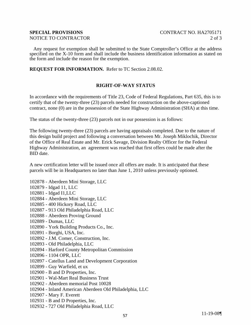
SPECIAL PROVISIONS CONTRACT NO. HA2705171 NOTICE TO CONTRACTOR 2 of 3
11-19-08¶
Any request for exemption shall be submitted to the State Comptroller’s Office at the address specified on the X-10 form and shall include the business identification information as stated on the form and include the reason for the exemption. REQUEST FOR INFORMATION. Refer to TC Section 2.08.02.
RIGHT-OF-WAY STATUS
In accordance with the requirements of Title 23, Code of Federal Regulations, Part 635, this is to certify that of the twenty-three (23) parcels needed for construction on the above-captioned contract, none (0) are in the possession of the State Highway Administration (SHA) at this time. The status of the twenty-three (23) parcels not in our possession is as follows: The following twenty-three (23) parcels are having appraisals completed. Due to the nature of this design build project and following a conversation between Mr. Joseph Miklochik, Director of the Office of Real Estate and Mr. Erick Savage, Division Realty Officer for the Federal Highway Administration, an agreement was reached that first offers could be made after the BID date. A new certification letter will be issued once all offers are made. It is anticipated that these parcels will be in Headquarters no later than June 1, 2010 unless previously optioned. 102878 - Aberdeen Mini Storage, LLC 102879 - Idgad 11, LLC 102881 - Idgad I1,LLC 102884 - Aberdeen Mini Storage, LLC 102885 - 400 Hickory Road, LLC 102887 - 913 Old Philadelphia Road, LLC 102888 - Aberdeen Proving Ground 102889 - Dumas, LLC 102890 - York Building Products Co., Inc. 102891 - Borghi, USA, Inc. 102892 - J.M. Comer, Construction, Inc. 102893 - Old Philadelphia, LLC 102894 - Harford County Metropolitan Commission 102896 - 1104 OPR, LLC 102897 - Catellus Land and Development Corporation 102899 - Guy Warfield, et ux 102900 - B and D Properties, Inc. 102901 - Wal-Mart Real Business Trust 102902 - Aberdeen memorial Post 10028 102904 - Inland American Aberdeen Old Philadelphia, LLC 102907 - Mary F. Everett 102931 - B and D Properties, Inc. 102932 - 727 Old Philadelphia Road, LLC

SPECIAL PROVISIONS CONTRACT NO. HA2705171 NOTICE TO CONTRACTOR 3 of 3
11-19-08¶
It is anticipated that the total right-of-way clearing date for the above captioned contract will be August 1, 2010. There are no relocation assistance services necessary for above-captioned contract. Right-of-way is being acquired in accordance with the FHWA directives. The SHA has determined that it is in the public interest to advertise in advance for construction of the total right-of-way clearance for the following reasons: The improvements to US 40 and MD 715 are needed to increase capacity and safety to accommodate the increase in volumes due to the additional base personnel being relocated to the Aberdeen Proving Grounds (APG) base as part of the US Defense Department's Base Realignment and Closure (BRAC) plan. Notice is hereby given in the contract proposal, in accordance with Title 23, Code of Federal Regulations, Part 635, that the lack of possession of any of these properties on this project may interfere with construction operation. The SHA will not honor any claim for inconvenience or delay caused by the lack of clear right-of-way. Notice will be given that an extension of time will be granted, if necessary, for delays caused by the interference beyond the time of notice to proceed.
REQUIRED PERMITS
For permit information please refer to TC Section 2.07.02.7, Permits All permits obtained by SHA will be inserted here upon approval.

SPECIAL PROVISIONS CONTRACT NO. HA2705171 NOTICE TO CONTRACTOR 1 of 1
10-31-08
NOTICE TO CONTRACTOR EARLY SUBMISSIONS. The last sentence of the first paragraph of TC-5.02, “No work shall be started before receipt of the Notice to Proceed” shall not apply to the following: After notification to the Contractor from the Administration that the Contractor is the apparent low bidder, the Contractor will be permitted to provide a written request to the Engineer to submit documentation for materials sources and working drawings for any items of work that have a long lead time and could jeopardize the project schedule. Upon written approval from the Engineer the Contractor may submit the applicable documentation to the Engineer. Should the Contract not be awarded to the apparent low bidder who meets the requirements of the Contract, GP-8.10 will apply for all costs accrued for the preparation and approval of the working drawings and any resultant material purchase approved by the District Engineer and steel fabricated in conformance with the approved working drawings between the date the Contractor received notice of apparent low bidder and the date of notice that the apparent low bidder will not be awarded this Contract. Should this Contract not be awarded to the apparent low bidder due to failure of the Contractor to comply with all award and execution requirements, all costs accrued for the preparation of the specific items and any resultant material purchased and steel fabrication shall be borne by the Contractor. Failure of the Contractor to submit the early submissions will not be basis for delaying issuance of the Notice to Proceed or be considered a reason for a time extension.

SPECIAL PROVISIONS CONTRACT NO. HA2715171 BIDDING REQUIREMENTS AND CONDITIONS 1 of 32
4/22/2010
TERMS AND CONDITIONS
TC SECTION 2 BIDDING REQUIREMENTS AND CONDITIONS FOR DESIGN-BUILD
TC 2.03 VALUE ENGINEERING CHANGE PROPOSALS
DELETE: This entire section.
ADD: Value Engineering proposals will not be entertained on this project.
TC 2.06 PARTNERING
DELETE: This entire section.
INSERT: The following:
Partnering on this project will be mandatory. The partnership will be structured to draw on the strengths of each organization through open communication, teamwork and cooperative action to identify and achieve mutual goals. The objective is to create an atmosphere of trust and honest dialogue among all stakeholders. This partnership will not change the legal relationship of the parties to the Contract nor relieve any party from any of the terms of the Contract.
The Administration's Assistant District Engineer of Construction, the Project Design Engineer and the Design-Builder’s management representative will organize a partnering project team. Persons recommended being on the team and guidelines for partnering are included in the Partnering Field Guide at www.mdqi.org.
The kick-off workshop meeting will be held soon after execution of the Contract. All stakeholders will attend the kick-off workshop to develop and commit to the Partnering Charter and Issue Resolution process. Follow-up meetings will be held monthly by the Design-Builder and the Administration, with other stakeholders attending as needed.
Measuring the partnering on the project is a key element to its success. All stakeholders will participate in the process. The Partnering Project Rating form will be completed monthly and then entered into the Administration’s Partnering Data Base. Summaries of the ratings will then be shared with the team. The Administration’s and Design-Builder’s management team will review the partnering ratings and intervene if necessary on a monthly basis.
All cost of partnering meetings shall be shared equally between the Design-Builder and the Administration.

SPECIAL PROVISIONS CONTRACT NO. HA2715171 BIDDING REQUIREMENTS AND CONDITIONS 2 of 32
4/22/2010
TC 2.07 REQUEST FOR PROPOSALS (RFP)/ INVITATION FOR BID (IFB)
2.07.01 Design-build Concept
The Administration is soliciting Technical Proposals and Price Bids for the design and construction of improvements to the US 40 and MD 715 Interchange and to MD 715 from north of US 40 Interchange to the Security Gate at Aberdeen Proving Grounds (APG). The basis of payment for this work will be “lump sum” which price shall include all costs associated with design and construction of the project in accordance with the requirements of this RFP/IFB.
The use of the term “Contractor” or “Design-Builder” within the Contract Documents furnished by the Administration shall be taken to mean Design-build (D/B) Contractor. These terms are interchangeable.
The use of the term "Designer" or "Design-build Engineer," within the Contract Documents furnished by the Administration, shall be taken to mean the Engineer working for the Design-build Contractor. The use of the term "Engineer," within the Contract Documents furnished by the Administration, shall be as defined in Section GP-1.03 of the General Provisions for Construction Contracts.
2.07.01.1 Restrictions on Participation in Design-Build Contracts:
An individual or entity that has received monetary compensation as the lead or prime design consultant under a contract with the Administration to develop the concept plan and/or have been retained to perform construction phase services on behalf of the state, or a person or entity that employs such an individual or entity, or regardless of design phase responsibilities received in excess of $500,000.00 for services performed, may not submit a technical proposal or a price proposal for this procurement and is not a responsible bidder under COMAR 21.06.01.01. The technical proposal or price proposal from such an individual or entity will be rejected pursuant to COMAR 21.06.01.01 and COMAR 21.06.02.03.
The following is a list of consultants and/or subconsultants that have received monetary compensation under a contract with the Administration as the prime consultant to develop the concept plan or has been retained by the Administration to perform construction phase services on the behalf of the state for this procurement or has received payment in excess of $500,000. SHA makes no representations regarding the completeness of the list: A. URS Corporation
B. KCI Technologies, Inc
C. The Wilson T. Ballard Company
D. Sabra, Wang & Associates, Inc
E. RJM Engineering, Inc.
F. Jacobs

SPECIAL PROVISIONS CONTRACT NO. HA2715171 BIDDING REQUIREMENTS AND CONDITIONS 3 of 32
4/22/2010
In addition, the State Ethics Commission administers the provisions of the State Ethics Law, including § 15-508 of the State Government Article that contains various restrictions on participating in State procurements. Any questions regarding eligibility must be appealed to the Commission.
No official or employee of the State of Maryland, as defined under State Government Article, §15-202, Annotated Code of Maryland, whose duties as such official or employee include matters relating to or affecting the subject matter of this contract, shall during the pendancy and term of this contract and while serving as an official or employee of the State become or be an employee of the Consultant or an entity that is a subcontractor on this contract.
No official or employee of the Maryland Department of Transportation (MDOT), during his tenure or for one year thereafter shall have any interest, direct or indirect, in this Contract or the proceeds thereof, regardless of whether they participated in matters relating to this contract while in the employ of the MDOT.
2.07.02 Project Description
The project consists of the design and/or construction of:
Widening of the MD 715 bridge over US 40 to included an additional lane in each direction
Widening of MD 715 to include two additional lanes in each direction from US 40 interchange to Cirelli Ct.
Re-stripping to provided three lanes in each direction at the MD 715 bridge over Amtrak
Widening of MD 715 to provide three lanes in each direction from Amtrak bridge to North of Aberdeen Proving Grounds (APG) entrance
MD 715 and Old Philadelphia Road intersection modification to include exclusive through, right and left movements on Old Philadelphia Road
This project has an accelerated construction start date. Construction must start on or before October 1, 2010. In order to facilitate this aggressive start date, SHA has coordinated with the Maryland Department of the Environment (MDE) to obtain a Storm Water Management (SWM) permit and E&S approval for this project. A section of improvements on MD 715 from the MD 715 bridge over Amtrak to North of Aberdeen Proving Grounds (APG) entrance (Phase 1) has been 100% permitted and approved by MDE for construction. The remainder of the project improvements (Phase 2) has been conceptually approved by MDE as part of this SWM permit and E&S Approval and the Design-Builder will need to submit permit modifications as outlined elsewhere in this Request for Proposal/Invitation for Bids.
SHA is providing Approved for Construction plans for Phase 1 of this project in PDF format on Projectwise with corresponding design files. These approved Phase 1 plans include Typical Sections, Paving Details, Geometric Layout, Roadway Plans, Intersection Details, Roadway Profiles, Drainage Plans, Stormwater Management Plans, Stormwater Management Details, Pipe Profiles, Drainage Details, and Erosion & Sediment Control Plans. These plans are approved for the following Phase 1 construction activities: excavation, embankment, pavement, drainage and stormwater management.

SPECIAL PROVISIONS CONTRACT NO. HA2715171 BIDDING REQUIREMENTS AND CONDITIONS 4 of 32
4/22/2010
An Approved Pavement and Geotechnical Report for Phase 1 has been provided on Projectwise.
The State Highway Administration anticipates that the Phase 1 Maintenance of Traffic be preformed utilizing the Book of Standards for Highway & Incidental Structures. Applicable standards shall be selected by the Design-Builder and submitted for review as outlined elsewhere in this RFP/IFB.
The completion of the reminder of the Phase 1 Design activities shall be performed by the Design-Builder and approved by the Administration, subject to language included elsewhere in this RFP/IFB.
SHA is providing conceptual Phase 2 plans in PDF format and corresponding design files on Projectwise. The overall concept design must be evaluated and design completed by the Design-Builder to ensure all project requirements are met, including drainage and stormwater management all within the right of way. The completion of the Phase 2 project documents shall be performed by the Design-Builder and approved by the Administration, subject to language included elsewhere in this RFP/IFB.
The Design-Builder’s lump sum bid shall incorporate all design and construction costs associated with both Phase 1 and Phase 2. The lump sum bid shall be based upon the Design-Builder’s calculated cost of the entire project. Any quantity discrepancies between the Design-Builders estimated items and quantities based on the Phase 1Approved for Construction Plans and actual items and quantities used shall not be a basis for additional payment.
The current status of aspects of the project is as outlined below.
2.07.02.1 Survey
Aerial photogrammetry was at 1” = 50’ prepared from photographs. A contour surface model and topographic base map were prepared on the basis of this photogrammetry. Supplemental data collector surveys were performed along all roadways to refine pavement elevations, ditch inverts, and pipe culverts. The data from these supplemental surveys was incorporated into the plan and the surface. This information is available in electronic format on the PROJECTWISE provided by the Administration. All Surveys were preformed in the Maryland State Grid, NAD 83/91 and NAVD 88. The Design-Builder must obtain all additional survey data necessary for their design, construction, and verification of surface model for all design activities.
2.07.02.2 Plans
A set of conceptual plans for the highway construction has been prepared in Microstation V8. Files are available in electronic format.
2.07.02.3 Cross-Sections
Field-surveyed cross-sections were not taken. Conceptual cross sections were prepared for the mainline and intersecting streets on the basis of the terrain model

SPECIAL PROVISIONS CONTRACT NO. HA2715171 BIDDING REQUIREMENTS AND CONDITIONS 5 of 32
4/22/2010
surface for the baseline, typical section and profile shown on the plans. These cross sections are being provided in electronic format for informational purpose only. The Design-Builder must perform field-run cross-sections to complete design and construction activities to address design and/or construction issues and provide clarification where necessary. Cross-sections showing existing and proposed ground must be prepared by the Design-Builder using the appropriate computer software.
2.07.02.4 Geotechnical
The Administration has obtained soils borings at selected locations along the project corridor and performed laboratory testing of the samples. The boring logs and laboratory test data are included on ProjectWise.
The Administration has performed a topographic survey and topsoil testing. Results of the survey and laboratory test data are included on ProjectWise.
These studies were performed with reasonable care and recorded in good faith. The Administration considers the information Engineering Data and will stand behind its accuracy at the location it was taken. The Administration assumes no responsibility in respect to the sufficiency of the studies for design. The Contractor will need to perform additional geotechnical testing and analysis to complete the project. The Design-Build Team is responsible for performing a complete geotechnical program including additional borings, sampling, in-situ and laboratory testing, analysis, and design, as necessary to complete design and construction.
2.07.02.5 Utilities
All utility data of which the Administration is aware is reflected on the survey information. The Administration has had a utility designating service locate underground utilities which identified the existence of the utility at it’s horizontal location. Inaccuracies in information regarding the locations of an underground utility based on utility designation information shall be considered material only if the utility’s actual centerline location is more than three (3) feet distant from the horizontal centerline location shown in that information, without regard to vertical location. Additional utilities may be present in the area.
Utility test hole data was field collected at single point locations. Once uncovered, the utility’s horizontal and vertical location was verified using accurate survey techniques. The Administration considers this information Engineering Data and will stand behind its accuracy at the locations that it was taken.
The Design-Builder is responsible for obtaining all information that will be required to complete the roadway design and construction. The Administration has conferred with the utility companies with facilities in this area concerning the potential impact of this roadway construction. The Administration has worked with the utility companies which have affected facilities on this project to establish utility relocation priority phasing. The Design-Builder must coordinate and cooperate with other contractors that are expected to be relocating utilities during the construction of this Project. The Design-Builder is responsible for determining the status of all designs

SPECIAL PROVISIONS CONTRACT NO. HA2715171 BIDDING REQUIREMENTS AND CONDITIONS 6 of 32
4/22/2010
and relocations and for identifying all additional required relocations and for coordinating the design and construction of the utilities with the design and construction of the roadway improvements of this Project.
2.07.02.6 Right of Way
All right of way will be cleared before Notice to Proceed is given. The Design-Builder may revise the roadway alignment and other details of the project to alter the limits of construction or disturbance, subject to environmental constraints, and the Administration’s approval but all construction must be contained within the Right of Way.
The Design-Builder will be responsible for acquiring, at its expense, all other rights in land needed for construction staging, yarding, construction, or otherwise.
2.07.02.7 Permits
The following permits and/or approvals are anticipated to be required for this project:
• Joint Federal/State Wetland and Waterways Permit and Water Quality Certification (WQC)
• Status of Maryland Department of Natural Resources Reforestation Permit
• Stormwater Management Permit (from MDE)
• Erosion and Sediment Control Approval (from MDE)
• Maryland Historic Trust (MHT) Approval
• Federal Aviation Administration (FAA) Approval
• Utility Permits
Status of Joint Federal/State Wetland and Waterways Permit and Water Quality Certification (WQC)
A Joint Federal/State Permit for wetland impacts is required for this project. Changes to the Conceptual Plans may result in the need for a permit modification in which case the Design-Build Team is responsible for supplying to the Administration all information needed in order to obtain approval and authorization from the regulatory agencies. The Design-Build Team shall be responsible for addressing any comments or issues the regulatory agencies and/or Administration may have, including those pertaining to avoidance and minimization measures. The Design-Build Team shall also be responsible for designing, implementing, and monitoring mitigation, if required. It is not the responsibility of, nor guaranteed by, the Administration that approval or authorization will be granted by the regulatory agencies.

SPECIAL PROVISIONS CONTRACT NO. HA2715171 BIDDING REQUIREMENTS AND CONDITIONS 7 of 32
4/22/2010
Several wetlands and waterways were identified and delineated within the project area. A copy of the delineation report will be made available to the Design-Build Team upon request. Surveyed boundaries of waterways, wetlands, and 25-foot wetland buffers are depicted on the Conceptual Plans, and will be provided to the Design-Build Team in electronic format as part of the Project Files. Prior to performing any work on the project, the Design-Build Team shall be responsible for installing temporary orange construction fence and prohibitive signage around the wetland and waterways areas within the immediate work area, as described in the Special Provisions. Impacts to all delineated resources have been minimized. Due to minimal impact, no Environmental Monitor is required. However, if changes to the Conceptual Plans result in additional impact, an Environmental Monitor may be assigned by the Administration.
Changes to the Conceptual Plans may result in permit modifications, which may or may not be approved. The Design-Build Team is responsible for supplying to the Administration all information needed to obtain any necessary permit modifications.
Joint Permit Application for this project was submitted on March 15, 2010 and is currently under review.
Status of Maryland Department of Natural Resources Reforestation Permit:
The Administration has coordinated with the Maryland Department of Natural Resources (DNR) Reforestation site review for forested impacts for this project based upon the proposed activities and contingent upon the submission of plans that are consistent with the proposed activities for which the approval was given. The completion of final design and construction activities might result in revocation of this approval if impacts exceed those for which the approval was granted. In this case, the Design-Build Team is responsible for the complete process of preparing the documentation for these approvals and submitting this information to SHA- Landscape Operations Division for approval, who will then submit the modification request to DNR for approval.
Status of Stormwater Management Review:
A Stormwater Management permit has been obtained for this project. As part of this permit, MDE has approved the Stormwater Management design for the section of MD 715 from the MD 715 bridge over Amtrak to North of Aberdeen Proving Grounds (APG) entrance.
For the remainder of the project a concept design was developed to establish Right of Way needs and to demonstrate to MDE that the stormwater management needs for the project can be accomplished within the available right-of-way. MDE approved the methodology in the concept stormwater management report as part of the Stormwater Management permit for this project.
The Design-Builder is responsible for finalization of the SWM design for the entire project, modifying the Stormwater Management permit and obtaining the final approvals from MDE.

SPECIAL PROVISIONS CONTRACT NO. HA2715171 BIDDING REQUIREMENTS AND CONDITIONS 8 of 32
4/22/2010
Status of Erosion and Sediment Control Approval:
MDE has approved the erosion and sediment control design for the section of MD 715 from the MD 715 bridge over Amtrak to North of Aberdeen Proving Grounds (APG) entrance.
For the remainder of the project, a concept erosion and sediment control design was developed to establish Right of Way needs and to demonstrate to MDE that all of the erosion and sediment control needs of the project can be accomplished within the available right-of-way.
The Design-Builder is responsible to finalize the erosion and sediment control for the entire project, and obtaining the final approvals from MDE.
Maryland Historic Trust (MHT) Approval:
The Administration has coordinated with MHT and received a letter of concurrence on November 20, 2009 there are no historic properties effect by this project.
Federal Aviation Administration (FAA) Approval:
This project is in the vicinity of Aberdeen Proving Grounds Airport. The Administration has reviewed the Approved for Construction plans for Phase 1 and found that no coordination is need with FAA for these plans provided the Design Builder does not violate any of the requirements outlined in TC 3.09. The Design-Builder shall be responsible for coordination with the Administration, Aberdeen Proving Grounds and FAA to obtain any required approvals for remainder of the project improvements.
Utility Permits:
Once the utility plans are approved for construction by the utility owners, the Design-Builder will be responsible for obtaining all the necessary utility permits from SHA to perform utility work within the project.
2.07.03 RFP/IFB Package
The following materials are being provided to all prospective bidders:
A. One copy of this RFP/IFB.
The following materials are being provided in electronic format on ProjectWise. This material is considered Engineering Data and the Administration will stand behind its accuracy unless otherwise specified in the contract documents.
B. Approved for Construction
o Phase 1 Plans & Cross-Sections
o Phase 1 Design Files

SPECIAL PROVISIONS CONTRACT NO. HA2715171 BIDDING REQUIREMENTS AND CONDITIONS 9 of 32
4/22/2010
Horizontal Baseline file
Vertical Alignment file
Shading file
Proposed Grading Files
SWM Files
Erosion and Sediment Control Files
Drainage Files
Layout Files
Border Files
Cross Section Files
o Phase 1 Pavement and Geotechnical Report
o Phase 1 Stormwater Management Report
C. Survey/Topographic Files
o Topographic files
o Text files
o Existing Contour files
o Triangle files
o Environmental Features file
o Bridge Location files
o Existing Surface files
o Intergraph Output/Coordinate files
D. Utility Files
o Utility designation file
o Utility Test Pit files
E. Right-of-Way
o Work Map files

SPECIAL PROVISIONS CONTRACT NO. HA2715171 BIDDING REQUIREMENTS AND CONDITIONS 10 of 32
4/22/2010
o Proposed Right-of-Way Line file
o Plats
F. Landscaping, Reforestation & Wetland Plates Files
o Wetland Impact Plates
o Wetland Impact Plates Design Files
o Landscaping and Forest Impact Plates
o Landscaping and Forest Impact Plates Design Files
G. Appendices
o Data Repot Elements
o Soils Laboratory Test Results (Appendix A)
o Network Pavement Performance Data (Appendix B)
o Soil and Foundation Boring Logs (Appendix C)
o Pavement Boring Logs (Appendix D)
o SWM Boring Logs (Appendix E)
o Field Infiltration Tests Tabulation (Appendix F)
o Existing and Proposed Traffic Data
o Utility Test Hole Reports
The following materials are being provided in electronic format on ProjectWise. This material is considered Conceptual and the Administration makes no representation regarding its accuracy.
H. Phase 2 Conceptual Plans & Cross-Sections
o Typical Section Sheets
o Geometry Sheets
o Miscellaneous Detail Sheets
o Roadway Plan Sheets
o Roadway Profile Sheets
o Conceptual Structure Plans

SPECIAL PROVISIONS CONTRACT NO. HA2715171 BIDDING REQUIREMENTS AND CONDITIONS 11 of 32
4/22/2010
I. Phase 2 Conceptual Design Files
o Title Sheet
o Horizontal Baseline file
o Vertical Alignment file
o Shading file
o Drainage
o Layout files
o Cross Section files
o Border files
o Stream Relocation Files
J. Conceptual Utility Plans
o Aberdeen Water and Sewer and Harford County Water
o BG&E Gas
o BG&E Electric
o Verizon
o Comcast
The following materials are being provided in electronic format on ProjectWise. This material is considered necessary for the Design-Build Team to submit a technical proposal, prepare a bid and/or finalize the Stormwater Management/Drainage designs.
K. Design-Builder’s Information Forms
o Design-Builder’s Key Management and Staff Information (Form A-1)
o Design-Builder’s Project Description (Form A-2)
o Erosion Sediment Control Past Performance Form
L. Stormwater Management and Surface Drainage Information
o Drainage Design Guidelines
o Concept Stormwater Management Report
o BMP Checklists and As-Built Certification Formats

SPECIAL PROVISIONS CONTRACT NO. HA2715171 BIDDING REQUIREMENTS AND CONDITIONS 12 of 32
4/22/2010
o SWM Report Format Guidelines
o SHA BMP Identification Form
o Grass Channel Credit Paper
o Water Quality Summary Sheet Format and Definitions
o Bioretention Facility Suggested Plants
o Geotextile Guidelines
o MDE Guidelines
o Stormwater Management Facility Visual/Environmental Quality and Safety Criteria: Review Guidelines, SHA Highway Hydraulics Division, October 2006.
M. Utility Specifications
o Aberdeen Approved Materials List
o Harford County DPW Design Guide
o Harford County Standard Specifications
N - Bridge As-builts
O - APG Specifications & Standards
o Standard Details for Chain-Link Security Fences
In general, the Microstation files included on ProjectWise are in conformance with the Microstation V8.
It is likely that most bidders will use plot drivers that differ from the drivers used to produce the provided plans. Some of the drawings screen existing features through level symbology color 250. The manipulation of the drawing files to produce any requirements (as found elsewhere in the Invitation for Bids) for as-built plans will be the responsibility of the selected Design-Builder.
Bidders are also provided with a file index provided on the ProjectWise. The file is a Word Document describing all the files and files names as outlined above.
2.07.04 Description of Work
2.07.04.1 Engineering/Construction Services
The required engineering and construction services to be provided by the Design-Builder will include, but not be limited to:

SPECIAL PROVISIONS CONTRACT NO. HA2715171 BIDDING REQUIREMENTS AND CONDITIONS 13 of 32
4/22/2010
Roadway Design and Construction.
Structural Design and Construction for All Bridges, Culverts, Retaining Walls, Noise Walls and any and all other incidental structures specifically required for this project.
Hydraulic Analysis, Design, Construction and Agency Approval for Specific Structures identified in the Contract Documents.
Signing, Lighting, Signaling and Pavement Marking Design and Construction.
Roadside Landscape Planting, Stormwater Management Landscape Planting, Reforestation Design and Construction of the aforementioned.
Utility Coordination for utility modifications whether designed and/or constructed by the Design-Builder.
Utility Relocations and Permits.
Storm Water Management (SWM) Design, Approvals, Construction and As-Built Certification (including MDE approval).
Erosion and Sediment Control (E&S) Design, Implementation and Approvals (including NPDES and MDE Approvals).
Engineering Studies.
General Coordination with Administration (includes obtaining required approvals).
Additional Data Collection (includes surveying, geotechnical, etc.).
Produce Required Deliverables.
Environmental Permit Activities (including obtaining permits as described herein).
Community Relations.
Traffic Control Design and Implementation.
Maintenance of project site(s) including mowing, watering, and dust control.
Water and Sewer Relocations
Obtaining all required permit modifications from the appropriate regulatory agencies for any additional impacts to wetlands, their buffers, waterways, floodplains, roadside trees, stormwater management, erosion and sediment control, or any other impacts not authorized by the original permits.
Any other items to successfully complete the project

SPECIAL PROVISIONS CONTRACT NO. HA2715171 BIDDING REQUIREMENTS AND CONDITIONS 14 of 32
4/22/2010
TC 2.08 PROPOSAL SUBMISSION REQUIREMENTS
2.08.01 Responsibilities of the Bidders
2.08.01.1 Review of RFP/IFB and Plans
Before submitting a proposal, the Prospective Bidder is responsible for examining the RFP/IFB and materials furnished to each prospective Design-Builder. The Design-Builder is responsible for all site investigation and preliminary design necessary to submit proposals and accept responsibility that their bid is sufficient to complete all design and construction.
2.08.01.2 Site Investigation
The Administration is acquiring the Right of Way necessary to construct this project. All necessary Right of Way will be acquired prior to Notice to Proceed. As of the issuance of this RFP/IFB, the Administration has advanced sufficiently in this process to permit Design-Builder’s to inspect all of the project site except for the areas specified in Right of-Way Status Special Provision. The Design-Builder’s invited to submit a Price Proposal must first examine all of the project site that is under Administration control. Examination of all other areas must be arranged with the owner.
The Prospective Bidder is solely responsible for all site conditions discoverable from a reasonable site examination. A reasonable site examination includes all utility and/or geotechnical investigation that the Prospective Bidder determines is necessary to properly price the Work. If the Prospective Bidder determines, before submission of the Price Bids, that additional utility designation, geotechnical and/or subsurface investigation or analysis are necessary to properly price the Work; it is the responsibility of the Prospective Bidder to perform such investigation and analysis at its expense. The Administration has performed a preliminary utility designation and geotechnical survey of the project site. The boring logs and test results have been included in the project files. The utility information is included in the data provided including utility test hole data included on ProjectWise. It is the Bidder’s responsibility to verify that information as part of its utility and/or geotechnical investigation. Price Bid submission will be considered conclusive evidence that the Prospective Bidder has determined that it has performed a reasonable site investigation to bid, design and construct the project.
All subsurface investigations performed by the Prospective Bidder, including sampling and laboratory testing, shall be performed by a Geotechnical firm experienced in subsurface investigations and in accordance with the 1988 AASHTO Manual on Subsurface Investigations, AASHTO Standards, the Maryland State Highway Administration Standard Specifications for Subsurface Explorations, MSMT Standards, the Maryland State Highway Administration Book of Standards for Highway and Incidental Structures, and ASTM Standards. The Prospective

SPECIAL PROVISIONS CONTRACT NO. HA2715171 BIDDING REQUIREMENTS AND CONDITIONS 15 of 32
4/22/2010
Bidder shall be responsible for utility clearance and any traffic control required for his investigation. The Prospective Bidder shall submit all Maintenance of Traffic concepts related to site investigation to the SHA District 4Traffic Division for approval. Any investigative methods that pose a safety threat to the traveling public shall not be used. Any borings taken in roadway or shoulder areas shall be backfilled before the area is re-opened to traffic. The Prospective Bidder shall restore to its current condition, any area of the site disturbed by his site investigation operations. If the Prospective Bidder encounters any abnormal conditions that indicate the presence of hazardous materials or toxic waste during his site investigation, he shall immediately suspend work in the area and notify the Administration. A Geotechnical Engineer who is registered in the State of Maryland shall supervise all subsurface investigations conducted by the Design-Builder.
2.08.01.3 Utility Coordination
Prior to submitting a Price Bid, the Prospective Bidder must conduct utility research and coordination with all utility companies along with additional site research to determine:
a. What utility relocation work is planned, what is the status and anticipated schedule impact of this work.
b. What utility facilities actually exist within the project limits.
c. What additional utility relocation work must be included in their design and impact to the schedule that will result from the Design-Builder's activities.
d. What permitting modifications result from additional utility relocations.
The Price Bid must represent a thorough consideration of these elements.
2.08.01.4 Additional Surveys
The Prospective Bidder will require additional survey or topographic information (including utility locations). The Design-Builder must account for these services within their project schedule and design submittals. It is the responsibility of the Prospective Bidder at its expense to obtain all additional information and the Administration accepts no responsibility for the lack of this information.
2.08.01.5 Duty to Notify if Errors Discovered
Bidders shall not take advantage of any error, omission, or discrepancy in the RFP / IFB or related materials, including all Project information. If a Bidder discovers such an error, omission or discrepancy, he shall immediately notify the Administration in writing; failure to do so notify shall constitute a waiver of any claim based upon such error, omission, or discrepancy. After such notification, the Administration will confirm or modify the RFP/IFB in writing as the Administration determines may be necessary to fulfill the intent of the RFP/IFB.

SPECIAL PROVISIONS CONTRACT NO. HA2715171 BIDDING REQUIREMENTS AND CONDITIONS 16 of 32
4/22/2010
2.08.02 Pre-Submittal Requirements
2.08.02.1 Communications During Proposal Preparation
The Procurement Officer’s Designatee in this RFP/IFB, or a representative hereafter designated in writing by the Procurement Officer, is the Administration's single contact and source of information for this procurement.
The following rules of contact shall apply during the Contract procurement process, which began upon the date of issuance of the RFP/IFB and will be completed upon the earliest to occur of (1) execution of the Contract, (2) rejection of all Proposals or (3) cancellation of this procurement. These rules are designed to promote a fair, unbiased, and legally defensible procurement process. Contact includes face-to-face, telephone, facsimile, electronic-mail (e-mail), or formal written communication.
The specific rules of contact are as follows:
1. Section 11-205 of the State Finance and Procurement Article, Annotated Code of Maryland, prohibits and penalizes collusion in the State procurement process.
2. After submission of the Technical Proposal, neither a Proposer nor any of its team members may communicate with another Proposer or members of another Proposer's team with regard to the PROJECT or the Proposals. However, a Proposer may communicate with a Subcontractor that is on both its team and another Proposer's team, provided that each Proposer has obtained a written certification from the Subcontractor that it will not act as a conduit of information between the teams.
3. Unless otherwise specifically authorized by the Procurement Officer, a Proposer may contact the Administration only through the Procurement Officer and only in writing (mail e-mail or facsimile), and not orally. The Proposer's contacts with the Administration shall be only through a single representative authorized to bind the Proposer.
4. The Procurement Officer normally will contact a Proposer in writing through the Proposer's designated representative.
5. Neither a Proposer nor its agents may contact Administration employees, including Administration heads, members of the evaluation committee(s) and any other person who will evaluate proposals, regarding the PROJECT, except through the process identified above.
6. Any contact by a Proposer determined to be improper may result in disqualification of the Proposer.
7. The Administration will not be responsible for or bound by: (1) any oral communication, or (2) any other information or contact that occurs outside the official communication process specified herein, unless confirmed in writing by the Procurement Officer.

SPECIAL PROVISIONS CONTRACT NO. HA2715171 BIDDING REQUIREMENTS AND CONDITIONS 17 of 32
4/22/2010
All requests for additional information or clarification of the RFP/IFB and any other communication concerning this Project shall be submitted via e-mailed with return confirmation receipt. No verbal requests or personal visits will be honored. All written contacts shall be addressed to:
Mr. Kirk G. McClelland
Director, Office of Highway Development State Highway Administration
e-mail address: [email protected]
Only e-mailed inquires will be accepted. No requests for additional information or clarification to any other Administration office, consultant, or employee will be considered. All responses shall be in writing and will be disseminated only by posting on SHA’s website at www.marylandroads.com under Contracts, Bids & Proposals. All responses to questions on the RFP/IFB and addenda to the RFP/IFB will be posted on this site. Responses to questions and addenda will not be mailed out.
Only requests received by 4:00 p.m. EST on May 10, 2010 will be addressed. Questions will not be accepted by phone. Questions, only from the primary or secondary contact, must include the requestor’s name, telephone number, e-mail address, and the Proposer he/she represents.
A response to questions will be issued without attribution and posted sequentially on the SHA website. Multiple responses are anticipated. The last response will be posted not later than 5 calendar days prior to the Proposal due date.
2.08.02.2 Addenda
Interpretations, clarifications or modifications to this RFP/IFB or the Contract will be made by Addenda. Addenda will be distributed to each Prospective Bidder until the completion of Step 1 of the 2-Step process. Subsequent to the proposal submittal date, addenda will only be distributed to the primary contact for those firms invited to submit bids. Only interpretations, clarifications and answers to the questions included in Addenda or such writings shall be binding on the Administration.
2.08.02.3 Compliance with Applicable Law
In connection with this RFP/IFB and the Contract, Proposers shall comply with all applicable laws in all aspects in connection with the procurement process of this PROJECT and in the performance of the Contract.

SPECIAL PROVISIONS CONTRACT NO. HA2715171 BIDDING REQUIREMENTS AND CONDITIONS 18 of 32
4/22/2010
2.08.03 Proposal Delivery Formalities
2.08.03.1 Organization of Proposal Submittals
Prospective Bidders shall organize their Technical Proposal to match the organization specified in this RFP/IFB.
a. Separate Packages
Proposal submissions shall consist of two separate packages, a Technical Proposal as described in Section TC 2.09 and, if invited to do so, a Price Bid as described in TC 2.11.
b. Technical Proposal The Technical Proposal may be submitted in container(s) of the Prospective Bidder's choice provided that the material is neat, orderly, and incapable of inadvertent disassembly. Technical Proposal shall be submitted and bound using a three (3) ring binder with all pages are numbered consecutively. Each container shall be clearly marked as follows:
Prospective Bidder's Name
Technical Proposal
US 40 – Interchange at South Philadelphia Boulevard (US 40) and Short Lane (MD 715) – HA2705171
Container _of _
c. Price Bids ( If Requested )
The Price Bid shall be submitted on the Proposal Form supplied by the Administration and shall be delivered in a sealed envelope capable of holding 8½" x 11" documents without folding and clearly marked as follows:
Prospective Bidder's Name
Price Bid
US 40 – Interchange at South Philadelphia Boulevard (US 40) and Short Lane (MD 715) – HA2705171
d. Proposal Guaranty
The Proposal Guaranty shall be delivered with the Price Bid in a sealed business-sized envelope clearly marked as follows:
Prospective Bidder's Name

SPECIAL PROVISIONS CONTRACT NO. HA2715171 BIDDING REQUIREMENTS AND CONDITIONS 19 of 32
4/22/2010
Proposal Guaranty
US 40 – Interchange at South Philadelphia Boulevard (US 40) and Short Lane (MD 715) – HA2705171
e. Location and Deadline for Technical Proposal Submittal
Technical Proposals must be submitted no later than May 24, 2010 prior to 12 noon (prevailing local time). The proposal must be delivered to the following location:
Director, Office of Procurement and Contracts Fourth Floor, C-405 707 N. Calvert Street Baltimore, Maryland 21202
2.08.03.2 Number of Copies
One original and 5 copies of the complete Technical Proposal, shall be submitted as specified in this Section. A single original of the Proposal Guaranty and a single original of the Price Proposal shall be submitted as specified in this section.
2.08.03.3 Effect of Submitting Proposal
The signing of the Design-build Proposal Submission Form and Price Proposal Form, and the delivery of a Proposal represents (a) an offer by the Prospective Bidder to perform the Work for the Price submitted within the time(s) specified and in accordance with all provisions of the Contract Documents and (b) the Prospective Bidder's agreement to all the provisions of the RFP/IFB and Contract governing requirements and procedures applicable through execution of the Design-Build Contract. The Technical Proposal will become part of the Design-Build Contract.
By so signing the above referenced terms and by delivering the Proposal, the Prospective Bidder makes the following affirmative representations.
a. The bidder has reviewed all documents and undertaken all investigations that could significantly impact the cost, timeliness, quality, or performance of the Work. Specifically, the bidder has (a) carefully examined the RFP/IFB and all documents included or referenced therein, (b) carefully examined all available reports and data related to subsurface conditions, (c) become familiar with all applicable federal, state and local laws and regulations, (d) visited the site and made all reasonable visual investigations, and (e) correlated the information obtained from the above examinations and investigations.
b. The bidder has given the Administration written notice of all errors, omissions, or discrepancies in the RFP/IFB in accordance with Section TC 2.08.01.5.

SPECIAL PROVISIONS CONTRACT NO. HA2715171 BIDDING REQUIREMENTS AND CONDITIONS 20 of 32
4/22/2010
c. The bidder has determined that the RFP/IFB are generally sufficient to convey an understanding of all terms and conditions that could significantly impact the cost, timeliness, quality, or performance of the Work.
2.08.03.4 Withdrawals and Resubmittals of Proposals
A bidder may withdraw Proposals after delivery, provided the request for such withdrawal is made in writing or in person before the date and time set for submission of Proposal. The bidder may revise and resubmit a Proposal so withdrawn before said date and time.
TC 2.09 TECHNICAL PROPOSALS
As described more fully in TC 2.12, the Administration will employ a two-step selection process in determining the successful bidder. Step 1 will culminate with the submission of the Technical Proposal as described herein. Step 2; The Design-Builder’s submitting the top rated Technical Proposals may subsequently be invited to submit a Price Bid as described more fully in TC 2.11. The time allowed for preparation of a Price Bid is specified in the formal request for a Price Bid. Any addenda issued subsequent to Step 1 will only be issued to the single point of contact for the prospective Design-Builder. It shall be the responsibility of the Design-Builder to identify the single point of contact and confirm that all Design-Builder members, suppliers, etc. have received all addenda.
General: The Technical Proposal submittal shall contain concise narrative descriptions and graphic illustrations, drawings, and charts that will enable the Administration to clearly understand and evaluate the capabilities of the Design - Build team.
No Price Information: No price information of any kind shall be included in the Technical Proposal submitted.
Proposal Organization: Organization of the Technical Proposal shall comprise five parts, meet the specified page limitation, and correspond to the outline as follows:
o Cover Letter
o Team Experience
o Environmental Approach and Environmental Past Performance
o Project Management
Format:
o Paper. The Technical Proposal submittal shall be submitted on 8.5”-by-11” paper printed back to back where practical. Charts, exhibits, and other illustrative and graphical information may be on 11”-by-17” paper, but must be folded to 8.5”-by-11”, with the title block showing.

SPECIAL PROVISIONS CONTRACT NO. HA2715171 BIDDING REQUIREMENTS AND CONDITIONS 21 of 32
4/22/2010
o Type Font and Margins. The type face of all narrative text shall be at least 12-pt, either Arial or Times New Roman font, and all page margins must be at least ½” from sides and 1” from top and bottom. All pages shall be sequentially numbered not including the cover letter.
o Page Limits. The Technical Proposal submittal shall be limited to the number of pages defined below. No page limit will be imposed on the appendices, although the size of the appendix should be kept within reason.
o Finding tools, such as tables of contents and page dividers shall be utilized to make the submittals easily usable.
2.09.01 Cover Letter (Limit 2 Pages)
The cover letter includes mandatory information requirements. The Cover Letter will not be part of the evaluations. The cover letter must be addressed to: Maryland State Highway Administration (SHA) Attention: Mr. Robert Gay, Director Office of Procurement and Contracts Fourth Floor, C-405 707 North Calvert Street Baltimore, MD 21202
The submittal cover letter must be signed by individual(s) authorized to represent the Major Participant firm(s) and the lead Constructor firm(s). A Major Participant is defined as the legal entity, firm or company, individually or as a party in a joint venture or limited liability company or some other legal entity, that will be signatory to the Design–Build Contract with the Administration. Major Participant(s) will be expected to accept joint and several liability for performance of the Design–Build Contract. Major Participants are not design subconsultants, construction subcontractors or any other subcontractors to the legal entity that signs the Design–Build Contract.
If the design–build contracting entity will be a joint venture, or some other entity involving multiple firms, all Major Participant firms involved must have an authorized representative sign the cover letter. The cover letter shall include the following:
a. Names, main role and license or certification information of all Major Participant firms and the lead constructor and design firms if not a Major Participant firm, and other firms that are now being committed to the design–build team. You must include at least your lead design firm and your lead constructor firm in the design–build team at this time.
b. The primary and secondary individual contacts for the Major Participant firm(s) with address, phone number, and E-mail address where all communications from the Administration should be directed for this RFP/IFB phase.

SPECIAL PROVISIONS CONTRACT NO. HA2715171 BIDDING REQUIREMENTS AND CONDITIONS 22 of 32
4/22/2010
c. Include an affirmative declaration that indicates to the best knowledge and belief of each Major Participant Firm, including the lead design firm if not a Major Participant firm, the information supplied in the Technical Proposal is true and accurate.
d. Include a declaration that each Major Participant firm(s) and the lead design and lead constructor firm, if not a Major Participant firm, are prepared to provide the necessary financial, material, equipment, labor and staff resources to perform the project.
e. Include a declaration by the Major Participants that signatories are affirming their intent to enter into a legal organization that shall constitute the DB Team.
f. Include a general authorization for the Administration to confirm all information contained in the Technical Proposal submittal with third parties, and indicate limitations, if any, to such authorization.
g. Statement including the proposed legal structure of the Design –Build Contractor and Team.
As an attachment to the cover letter and excluded from the page limitation for this section, provide documentation that the lead Design Firmhas Professional Liability Insurance.
2.09.02 Team Experience (Page limits by subsection)
The Design-Builder must demonstrate their experience on comparable projects with detailed descriptions. Information that is not detailed or relevant may be considered below acceptable. The information for each staff member should be relevant to the role and function they will perform on this project. The resumes for key staff must identify the function the staff member will fulfill on this project and include their role or function on relevant projects if they are different from that proposed. The Administration strongly recommends that the single point of contact is a key staff member.
2.09.02.1 Lead Design firm experience: (3 pages max)
A. Experience and qualifications documentation
i. Submit resumes of the following key design firm management and staff, highlighting their relevant experience on similar type projects. If more than one key position is filled by the same person, so indicate.
1. Project Design Manager - Shall be a Maryland registered Professional Engineer who is an owner or employee of the lead design firm and shall have a minimum of fifteen (15) years demonstrated experience in managing design for projects of similar scope and complexity as this PROJECT. Emphasize experience with highway, structures and drainage design, utility relocations, permitting and projects of similar size and type. Emphasize Design-Build experience.
Resumes shall be a maximum of one (1) page each and shall follow attached Form A-1.

SPECIAL PROVISIONS CONTRACT NO. HA2715171 BIDDING REQUIREMENTS AND CONDITIONS 23 of 32
4/22/2010
ii. Using attached Form A-2, past Project Description, provide a listing of at least three (3) projects that highlight design experience relevant to this project, which the lead design firm performed over the last ten (10) years. Design-build experience is preferred. Use one (1) form per project.
2.09.02.2 Lead Constructor firm experience: (5 pages max)
A. Experience and qualifications documentation
i. Submit resumes of the following key design firm management and staff, highlighting their relevant experience on similar type projects.
1. Design–Build Project Manager - Shall have a minimum of fifteen (15) years demonstrated experience in construction and management of construction on highway projects with similar size, type of work, and complexity as this PROJECT. Emphasize Design-Build experience and extensive project management experience.
2. Construction Manager - Shall have a minimum of ten (10) years demonstrated construction experience in civil works projects similar in nature to the PROJECT, and include highway construction, drainage construction, environmental sensitivity, utility coordination and relocation, and maintenance of traffic;
Resumes shall be a maximum of one (1) page each and shall follow attached Form A-1.
ii. Using attached Form A-2, past Project Description, provide a listing of at least three (3) projects that highlight construction experience relevant to this project, which the lead constructor firm performed over the last ten (10) years. Design-build experience is preferred. Use one (1) form per project.
2.09.03 Environmental Approach and Environmental Past Performance (Limit 8
Pages)
A. Environmental Permitting Elements: Demonstrate an understanding in words, necessary for the Administration to evaluate your approach to each of the seven (7) major environmental permitting elements of the Project, as specified herein. Your discussion shall be guided not only by this RFP/IFB Section and the Scope of Work, but also by the guidelines, performance requirements, and design and construction criteria set forth throughout other parts of the RFP/IFB Documents.
o Approach to coordinating with Federal, State, and local agencies to secure environmental permits.

SPECIAL PROVISIONS CONTRACT NO. HA2715171 BIDDING REQUIREMENTS AND CONDITIONS 24 of 32
4/22/2010
o Measures for ensuring compliance with requirements of the environmental approvals and laws relating to cultural and/or environmental resources.
o Approach to implementing an effective Storm Water Management Plan.
o Approach to implementing an effective Erosion and Sediment Control (E&S) plan including; interim E&S measures required during construction phasing, maintenance of controls while in place and frequency of inspecting E&S controls.
o Measures for ensuring a proactive approach to maintaining/correcting effective E&S control devices.
o Approach to interacting with MSHA’s Environmental Monitor, if required.
B. Environmental Stewardship: In words, necessary for the Administration to evaluate, discuss your experience or approach to each of the following three environmental stewardship elements. Your discussion shall be guided not only by this RFP/IFB Section and the Scope of Work, but also by the guidelines, performance requirements, and design and construction criteria set forth throughout other parts of the RFP/IFB Documents.
o Discuss innovative techniques, products and practices you have incorporated into your daily business that promotes environmental stewardship and the reduction of waste and pollution in design and construction. Include a discussion of performance measures and controls that you have in place to ensure complete follow through on these initiatives.
o Discuss project specific innovative techniques, products and practices you have incorporated into past projects that have resulted in the reduction of impacts to environmental features, or a reduction in waste or pollution. The techniques, products and practices outlined in this section should not be the same as those outlined above.
o Provide your current understanding of the major environmental features on this project, your general planned approach to ensure their protection and discuss any innovative techniques, products and practices you will utilize on this project to reduce any impacts to these features. The techniques, products and practices outlined in this section may be the same as those outlined above. Please include a discussion of quality control practices and procedures intended to be used to ensure that these proposed results are realized.
C. Erosion and Sediment Control Quality Assurance rating: (Note: the following
information shall be excluded from the maximum page requirement set for this Section)
o Provide record of Erosion and Sediment Control ratings for all projects ongoing
or completed within the last 4 years, using the Erosion Sediment Control Quality Assurance Ratings – Past Performance Form provided on ProjectWise. The Administration will evaluate past performance on the Quality Assurance ratings on projects where the Lead Constructor Firm was the prime contractor. Past

SPECIAL PROVISIONS CONTRACT NO. HA2715171 BIDDING REQUIREMENTS AND CONDITIONS 25 of 32
4/22/2010
performance will be evaluated for any project ongoing or completed within the last 4 years. Lead Constructor Firms that do not have previous experience with the Administration shall provide evidence of satisfactorily implementing erosions and sediment on any project ongoing or completed within the last 4 years.
D. Environmental violations: (Note: the following information shall be excluded from
the maximum page requirement set for this Section)
o Describe the circumstances surrounding any environmental violations associated with regulated wetlands and waterways received in the last five (5) years for which your firm received a fine or a stop work order imposed by either the Owner or a Regulatory agency.
2.09.04 Project Management (Limit 8 Pages)
General: The Design - Build team shall substantiate its ability to accomplish the Work by explaining its approach to project management by addressing the following elements:
A. Project Management Key Functions. Explain how the organization will perform the
following functions:
Communications Management: Provide means and methods for communicating with the Administration, community officials, the general public and other Stakeholders including environmental agencies. Also, indicate your expected benefits from participating in a formal Partnering Program with the Administration.
Change Management: Discuss how the Design – Builder will advise and
discuss with the Administration any potential changes in advance of any actual impact to the scope of work or the contract for which the Design – Builder believes the Administration is responsible. In addition, discuss how the design firm will be involved and have decision-making authority with respect to any changes to the “issued for construction” drawings, and for inclusion of such changes in a complete set of as-built drawings and specifications.
Safety and Health Management: Discuss your plan for safety management,
including safety of the traveling public, pedestrians, bicyclists, as well as your approach towards incident management.
B. Baseline Project Summary Schedule: Submit a Baseline Project Summary Schedule on an 11x17 inch page and supporting text that addresses the work requirements, including but not limited to the following:

SPECIAL PROVISIONS CONTRACT NO. HA2715171 BIDDING REQUIREMENTS AND CONDITIONS 26 of 32
4/22/2010
• Engineering and modeling • Geotechnical investigations • Preliminary list of technical design submittals for the
Administrations review, and your plan for developing and providing these submittals.(reference to defined construction work packages should be included)
• Permitting • Transportation Management Plan • Construction mobilization, including temporary construction
works, such as haul and access roads, • Construction and completion of permanent works • Major utilities relocations, including those that are part of the
contract or by others (3rd parties). • Site restoration and clean-up
The Baseline Project Summary Schedule shall not exceed 250 activities, and represent the entire project execution from design through completion and turnover. The Baseline Summary Schedule should establish major milestones to measure and assess progress, which includes any critical schedule dates indicated by the Administration in the schedule requirements of this RFP/IFB.
C. Organizational Structural: The Design - Build Team shall provide the following:
Explain how the Design-Build Team will be structured to function as an integrated entity. Your explanation should include, but not be limited to, discussion on how construction staff will be involved in the design activities and how design staff will be involved in construction activities.
Include an organization chart indicating the structure of the Design - Build team’s organization and the roles and responsibilities of each suborganization. The chart shall show the interrelationships of project management, interfaces with 3rd parties, design, project controls, construction, and quality control functions. The organizational chart shall reflect all Key Staff as identified in this RFP/IFB, in addition to persons proposed for the following positions:
Design Quality Manager Environmental Compliance Manager Project Utilities Coordinator Public Relations Coordinator

SPECIAL PROVISIONS CONTRACT NO. HA2715171 BIDDING REQUIREMENTS AND CONDITIONS 27 of 32
4/22/2010
The chart shall indicate the planned approximate percent of time for each Key Staff member as well as the individuals as indicated above that will be dedicated to the Project throughout the duration of the Project.
D. General Project Understanding and Approach:
Provide your current understanding of the Administration’s major objectives for this project and your general plan to meet those objectives. As part of you explanation, the following areas, at a minimum, should be addressed:
Your understanding of the larger group of project stakeholders including their identities and specific goals and the activities and/or methodologies that you will utilize within the scope of this project to address their goals.
How you will maximize safety and minimize disruption and delay to the traveling public, pedestrians, and bicyclists including minimizing roadway, ramp, lane, and shoulder closures.
How you will provide safe access to and from residential and commercial properties.
Your plan for coordinating with utility companies. This plan should included how you will coordinate with utility companies in design and construction to minimize delays, handle changes the utility companies may make to their design or changes made during their relocation construction, handle changes in your design or construction that may create utility issues or impacts, handle unforeseen issues in relation to utilities and your action plan for resolving these issues.
TC 2.10 EVALUATION OF TECHNICAL PROPOSALS
The Administration will use a two-step bidding process to select the successful bidder for this project. The Administration will first review and evaluate all Technical Proposals. Based on the results of these evaluations, a list of acceptable prospective bidders will be developed.
2.10.01 Technical Proposal – Evaluation Factors
The following elements of the Technical Proposal will be evaluated and rated on their content, accuracy and presentation. The elements and their importance that will be used in the evaluation process are noted as follows:
o Team Experience and Environmental Approach & Environmental Past Performance are of equal importance and are considered the most important.
o Project Management is considered the next most important.

SPECIAL PROVISIONS CONTRACT NO. HA2715171 BIDDING REQUIREMENTS AND CONDITIONS 28 of 32
4/22/2010
2.10.01.1 Technical Proposal Evaluation Committee
The Administration will assemble an Evaluation Committee consisting of key staff from appropriate offices within the Administration. The Evaluation Teams will review the Technical Proposals to verify that all requirements of the RFP/IFB have been met, and to evaluate the proposals based on the evaluation factors.
2.10.01.2 Evaluation Process
Members of the Committee will evaluate elements of the Technical Proposals as listed in 2.10.01.
2.10.01.3 Evaluation Results
The technical evaluation factors and the overall Technical Proposal will be rated by and adjectival (qualitative/descriptive) method. The following adjectival ratings shall be used in evaluation of each technical evaluation factor and the overall technical rating of the Proposal:
EXCEPTIONAL – The Proposer has demonstrated an approach that is considered to significantly exceed stated objectives/requirements in beneficial way to the Administration. This rating indicates a consistently outstanding level of quality, with very little or no risk that this Proposer would fail be meet the requirements of the solicitation. There are essentially no Weaknesses as defined below.
GOOD – The Proposer has demonstrated an approach that is considered to exceed stated objectives/requirements. This rating indicates a generally better than acceptable quality, with little risk that this Proposer would fail to meet the requirements of the solicitation. Weaknesses, if any, are very minor.
ACCEPTABLE – The Proposer has demonstrated an approach that is considered to meet the stated objectives/requirements. This rating indicates an acceptable level of quality. The Proposer demonstrates a reasonable probability of success. Weaknesses are minor and can be corrected.
UNACCEPTABLE – The Proposer has demonstrated an approach that indicates significant weaknesses/deficiencies and/or unacceptable quality. The Proposal fails to meet the stated criteria and/or lacks essential information and is conflicting and/or unproductive. There is no reasonable likelihood of success. Weaknesses/deficiencies are so major and/or extensive that a major revision to the Proposal would be necessary.
In assigning ratings the Administration may assign plus (+) or minus (-) suffix to further differentiate the strengths or limitations within a technical rating.
The term “weakness,” as used herein, means any flaw in the proposal that increases the risk of unsuccessful contract performance. A significant weakness in the proposal is a flaw that appreciably increases the risk of unsuccessful contract performance. The term “deficiency” means a material failure of a proposal to meet an RFP/IFB requirement or a

SPECIAL PROVISIONS CONTRACT NO. HA2715171 BIDDING REQUIREMENTS AND CONDITIONS 29 of 32
4/22/2010
combination of significant weaknesses in a proposal that increases the risk of unsuccessful contract performance to an unacceptable level.
Any Proposal that receives a rating of Unacceptable in one or more technical evaluation factors will receive an overall technical proposal rating of Unacceptable.
The technical proposal will become part of the contract documents and all concept ideas provided to the Administration are expected to be included in the price bid, final plans, design and construction phases. The Administration or successful bidder may use ideas and approaches excluding proprietary or protected information.
2.10.02 Determination of Reduced Candidate List
Based upon the evaluation process described above, the Technical Proposals will be assigned an overall adjectival rating. The Proposers submitting the most highly rated Technical Proposals will be invited to submit Price Bids. In order to be considered to submit a Price Bid, a Proposal must receive at least an “ACCEPTABLE“ on all technical evaluation factors
NOTE: All materials, conferences, proposals and other matters related to this project shall remain confidential until the contract is executed with the successful DB Team. However, the Administration does reserve the right to use the knowledge of good ideas of one team in discussions with the successful Team.
TC 2.11 PRICE BIDS
2.11.01 General
Price Bids will be accepted only from those Bidders invited by the Administration in writing to submit bids. Price Bids must be submitted using the Proposal Form included in this RFP/IFB.
Bids shall be submitted on a lump sum basis, and shall include all design, detail, construction, labor, materials, and all incidentals necessary to complete the details and construction of this project.

SPECIAL PROVISIONS CONTRACT NO. HA2715171 BIDDING REQUIREMENTS AND CONDITIONS 30 of 32
4/22/2010
2.11.02 Contract Completion Incentive Procedure
There is no Contract Completion Incentive on this project
2.11.03 Wetland and/or Waterway Impact Reduction Incentive
The Design-Build Team is advised that there will be a Wetland and/or Waterway Impact Reduction Incentive on this contract. See TC Section 3.20.07.04.03, Wetland and/or Waterway Impact Reduction Incentive contained within this RFP/IFB for the contract requirements.
2.11.04 Erosion Sediment Control Incentive/Liquidated Damage Payment
The Design-Build Team is advised that both an incentive and a liquidated damage will be imposed on this contract related to their erosion sediment control and will be tied to the Quality Assurance Ratings. See Special Provision 308.01.04, Quality Assurance Ratings contained within this RFP/IFB for the contract requirements.
2.11.05 Forest Impact Reduction Incentive
Not applicable
2.11.06 Proposal Guarantee
The Contractor's bid guarantee shall represent 5% of Part "A" of the Contractor's bid in accordance with the provisions of GP 2.07.
2.11.07 Liquidated Damages
In the event a complete usable facility is not provided by the calendar date specified on page 27 of 28 in the Proposal Form of the Invitation for Bids, a liquidated damage will be charged in accordance with the provisions of GP 8.09. The dollar amount of liquidated damages is stated on page 28 of 28 in the Proposal Form of the Invitation for Bids. The Administration will be the sole approving authority in determining when the project is considered a usable facility.
TC 2.12 BID OPENING AND AWARD
2.12.01 Bid Opening
If, in the judgment of the Administration, there are a sufficient number of top rated proposals, to ensure a competitive bidding process, the Administration will invite the top rated firms to submit Price Bids. These Price Bids will be publicly opened and evaluated. The project will be awarded in accordance with the Administration's bidding procedures.

SPECIAL PROVISIONS CONTRACT NO. HA2715171 BIDDING REQUIREMENTS AND CONDITIONS 31 of 32
4/22/2010
2.12.02 Award and Execution of Contract
All conditions of award, and award and execution procedures will be in accordance with GP-Section 3 of the Specifications.
The Design-Builder will be given Notice to Proceed after Execution of the Contract has been completed. At this point, additional field investigation may continue and design work may proceed with payment to be made as outlined in TC Section 7.11.
The Administration understands the probability that the successful low bidder will need to start design activities as soon as possible after notification as the apparent low bidder and prior to issuance of the Notice to Proceed. The Administration understands this approach is an effort to maximize the available time for construction activities. The Administration also recognizes the benefits to the public by providing an opportunity to accelerate project activities and project completion. It is reasonable that these design activities should not place the Design-Builder at risk should the Administration not issue a Notice to Proceed for events outside of the control of the Design-Builder.
The Administration will diligently process contract documents and procedures to issue a Notice to Proceed within the shortest time frame possible. In the event that the Administration does not issue a Notice to Proceed to the successful low bidder for reasons beyond the control of the bidder, the Administration will reimburse actual documentable design costs up to a maximum of $50,000 or 1% of the construction bid, whichever is greater, incurred by the Design-Builder after approval of the Bid Bond. To receive reimbursement, the Design-Builder must submit all design calculations, plans, surveys, boring data, updated electronic files, personnel time sheets and other materials to the Administration for its use.
Actual construction work may not begin until the additional requirements specified elsewhere in this RFP/IFB have been satisfied, including but not limited to receipt of erosion and sediment control plan approval, permits, design approval including appropriate maintenance of traffic approval, and pre-construction conference.
2.12.05 Stipend
The Administration understands that firms invited to submit price bids on Design-build projects may incur higher than normal bid preparation costs in their engineering effort to submit responsive bids for the project. Such efforts are likely to involve geotechnical investigations, development of horizontal and vertical geometry, development of concept design plans, cross sections, field surveys, stormwater management investigation, preliminary storm drain design, development of extensive design details to establish materials and quantities to prepare and submit a bid.
The Administration will agree to pay a stipend the design-build firms invited by the Administration to submit bids, which are not deemed the successful low bidder.
A stipend in the amount of $36,000 will be paid to each Proposer if its Proposal was not selected for Award or it was awarded the Contract but the Contract was terminated prior to issuance of a Notice to Proceed for the Administration’s convenience.

SPECIAL PROVISIONS CONTRACT NO. HA2715171 BIDDING REQUIREMENTS AND CONDITIONS 32 of 32
4/22/2010
Those firms invited to submit price proposals will be required to sign a contract with the Administration for payment of the stipend in exchange for electronic copy and hard copy of all documents used to develop the price proposal. The firm submitting the responsive winning bid shall not be eligible to receive the stipend.
In payment for the services covered by this Agreement, the Design-Build Team agrees that all materials, electronic files, marked up drawings, cross sections, quantity lists and other material used in the development and submission of the price proposal will become the property of the Administration and may be used in any manner at their discretion without any additional compensation to the Design-Build Team. Three completed, signed originals of the enclosed Agreement must be submitted to Mr. Kirk G. McClelland, Director, Office of Highway Development, in the time frame outlined in the Stipend Agreement, Section 2.2(a).
One original invoice signed (in blue ink) and two copies along with supporting engineering materials noted above must be submitted to Mr. Kirk G. McClelland, Director, Office of Highway Development, in the time frame outlined in the Stipend Agreement, Section 2.3. Invoices shall contain the following information:
Invoice # - created by the Design-Build Team
Federal Tax I.D. number
Remittance Address
Contract # - HA2705171
Contract Description – US 40 – Interchange at South Philadelphia Boulevard (US 40) and Short Lane (MD 715)
FMIS Construction # - HA270B51
Payment Amount - $36,000
Description of Work: example: "payment for Design-Build team to perform preliminary design work to prepare a bid for contract"

Maryland State Highway Administration
Stipend Agreement Page of 5
05-07-07
STIPEND AGREEMENT
Contract No. Project Description:
THIS STIPEND AGREEMENT (the “Agreement”) is made and entered into as of the ___ day of _________, 200_, by and between the STATE OF MARYLAND, acting by and through the Maryland Department of Transportation, State Highway Administration (the "SHA"), and _________________________ ("Proposer"), with reference to the following facts:
A. On __________, 200_, the SHA issued a Invitation for Bids (“IFB”) for design and construction of the (insert project description) Design-Build Project (“Project”), pursuant to procurement authority granted in State Finance and Procurement Article of the Annotated Code of Maryland and the Code of Maryland Regulations (“COMAR”), Title 21. The (insert project name) will be owned and operated by the State Highway Administration (SHA or Administration), which owns all non-tolled state highways and bridges in the State of Maryland (“State”). The Administration is responsible for administration of design and construction of the Project.
B. The IFB requires each Proposer to complete and deliver a Stipend Agreement to the SHA within the time frame noted below in 2.2 (a).
NOW, THEREFORE, Proposer hereby agrees as follows:
1. Work Product.
1.1 The SHA hereby retains Proposer to prepare and submit, in response to the IFB a price bid that conforms in all material respects to the requirements of the IFB, as determined by the SHA, are timely received by the SHA, and satisfy the provisions set forth in the IFB.
1.2 All work performed by Proposer and its team members pursuant to this Agreement shall be considered work for hire, and the Work Product (as defined below) shall become the property of the SHA without restriction or limitation on its use. Neither Proposer nor any of its team members shall copyright any of the material developed under this Agreement.
1.3 Proposer agrees that all Work Product is, upon receipt by the SHA, the property of the SHA. The term “Work Product” shall mean all submittals made by Proposer during the IFB process, including the Proposal, exchanges of information during the pre-proposal and post-proposal period. However, the term “Work Product” shall specifically exclude patented rights in previously existing proprietary technology.
1.4 In consideration for the SHA’s agreement to make payment hereunder, Proposer agrees that the SHA shall be entitled to use all Work Product, without any further compensation or consideration to the Proposer, in connection with the IFB, the Contract Documents, the Project and future procurements by the SHA. Notwithstanding the foregoing, SHA shall not be entitled to use information submitted by Proposer to the SHA in which the SHA determines is exempt from disclosure under the Maryland Public Information Act

Maryland State Highway Administration
Stipend Agreement Page of 5
05-07-07
(“PIA”), Title 10, Subtitle 6, Part III of the State Government Article of the Annotated Code of Maryland, unless the IFB otherwise provides.
1.5 The SHA acknowledges that the use of any of the Work Product by the SHA or the Design-Builder is at the sole risk and discretion of the SHA and the Design-Builder, and shall in no way be deemed to confer liability on the unsuccessful Proposer.
2. Compensation And Payment.
2.1 Compensation payable to Proposer for the Work Product described herein shall be $36,000 if all of the following conditions are met:
Proposer’s Proposal, was not the apparent low bidder or was not selected for award or it was awarded the Contract but the Contract was terminated by SHA for its convenience prior to issuance of a notice to proceed.
2.2 In its sole discretion, the SHA may pay compensation to Proposer, in an amount to be determined by the SHA, for the Work Product described herein under the following conditions:
(a) For any Proposer meeting the criteria identified in Section 2.1, above.
Any amount paid under this subparagraph (a) will not exceed $36,000 and will be subject to audit of the costs incurred by the Proposer in preparing its Technical Proposal and price bid. Auditors shall have access to all books, records, documents and other evidence and accounting principles and practices sufficient to reflect properly all direct and indirect costs of whatever nature claimed to have been incurred. Failure of the Proposer or its team members to maintain and retain sufficient records to allow the auditors to verify all or a portion of the claim or to permit the auditors access to the books and records of Proposer and its team members shall constitute a waiver of the right to be paid a stipend and shall bar any recovery hereunder.
Any Proposer wishing to apply for a stipend under this subparagraph (a) shall submit the completed Agreement to the SHA within 10 days of price proposals being opened. Eligibility of receipt of a stipend is dependent upon meeting the conditions set forth in Section 2.1. of this Agreement and TC Section 2.12.05 of the IFB.
(b) If the procurement is cancelled prior to the Bid Opening Date.
Proposers will be provided the opportunity, at their option, of delivering to the SHA the Work Product of their Proposal preparations to date. There is no specific format required for such Work Product. Those Proposers that choose to deliver their Work Product may be paid an amount that the SHA deems to be appropriate consideration for the Work Product. No portion of the stipend amount will be paid in the event a Proposer chooses not to deliver its Work

Maryland State Highway Administration
Stipend Agreement Page of 5
05-07-07
Product. Any amount paid under this subparagraph (b) will not exceed the amount identified in Section 2.1 and will be subject to the audit criteria in Section 2.2 (a).
2.3 Any payment of compensation owing hereunder will be made (i) within 30 days after receipt of a proper invoice submitted to the SHA under this Section 2.3 or (ii) if an award is made, when any complaint against award is administratively and judicially resolved. Such invoice and supporting engineering work may not be submitted until one business day after the earlier to occur of (a) notice by SHA that award of contract has occurred, or (b) cancellation of the procurement. Invoices must be received within 30 days of said notification by SHA to be honored for payment.
3. Indemnities.
3.1 Subject to the limitations contained in Section 3.2, Proposer shall indemnify, protect and hold harmless the SHA and its directors, officers, employees and contractors from, and Proposer shall defend at its own expense, all claims, costs, expenses, liabilities, demands, or suits at law or equity arising in whole or in part from the negligence or willful misconduct of Proposer or any of its agents, officers, employees, representatives or subcontractors or breach of any of Proposer’s obligations under this Agreement.
3.2 This indemnity shall not apply with respect to any claims, demands or suits arising from use of the Work Product by the SHA or its contractors.
4. Compliance With Laws.
4.1 Proposer shall comply with all federal, state, and local laws, ordinances, rules, and regulations applicable to the work performed or paid for under this Agreement and covenants and agrees that it and its employees shall be bound by the standards of conduct provided in applicable laws, ordinances, rules, and regulations as they relate to work performed under this Agreement. Proposer agrees to incorporate the provisions of this paragraph in any subcontract into which it might enter with reference to the work performed pursuant to this Agreement.
4.2 The Proposer agrees (a) not to discriminate in any manner against an employee or applicant for employment because of race, color, religion, creed, age, sex, marital status, national origin, ancestry or disability of a qualified individual with a disability; (b) to include a provision similar to that contained in subsection (a) in any subcontract except a subcontract for standard commercial supplies or raw materials; and (c) to post and to cause subcontractors to post in conspicuous places available to employees and applicants for employment, notices setting forth the substance of this clause.
5. Assignment.
Proposer shall not assign this Agreement without the SHA’s prior written consent. Any assignment of this Agreement without such consent shall be null and void.

Maryland State Highway Administration
Stipend Agreement Page of 5
05-07-07
6. Miscellaneous.
6.1 Proposer and the SHA agree that Proposer, its team members, and their respective employees are not agents of the SHA as a result of this Agreement.
6.2 All words used herein in the singular form shall extend to and include the plural. All words used in the plural form shall extend and include the singular. All words used in any gender shall extend to and include all genders.
6.3 This Agreement, together with the IFB, as amended from time to time, the provisions of which are incorporated herein by reference, embodies the entire agreement of the parties with respect to the subject matter hereof. There are no promises, terms, conditions, or obligations other than those contained herein or in the IFB, and this Agreement shall supersede all previous communications, representation, or agreements, either verbal or written, between the parties hereto.
6.4 It is understood and agreed by the parties hereto that if any part, term, or provision of this Agreement is by the courts held to be illegal or in conflict with any law of the State of Maryland, the validity of the remaining portions or provisions shall not be affected, and the rights and obligations of the parties shall be construed and enforced as if the Agreement did not contain the particular part, term, or provisions to be invalid.
6.5 This instrument may be executed in two or more counterparts, each of which shall be deemed an original, but all of which together shall constitute one and the same instrument.
6.6 This Agreement shall be governed by and construed in accordance with the laws of the State of Maryland.
IN WITNESS WHEREOF, the parties have executed this Agreement as of the date first written above.
STATE OF MARYLAND by STATE HIGHWAY ADMINISTRATION WITNESS/ATTEST:
____________________________________
Approved as to form and legal sufficiency:
Assistant Attorney General
Approved for Execution:
_____________________________________
Authorized Signature
Director, Office of Highway Development
Date:

Maryland State Highway Administration
Stipend Agreement Page of 5
05-07-07
[Signature for Corporations/LLCs] WITNESS/ATTEST:
____________________________________ Proposer Name
By (Seal)
Title:
Printed Name
Printed Name Federal ID # or Social Security #

SPECIAL PROVISIONS CONTRACT NO. HA2705171 SCOPE OF WORK FOR DESIGN-BUILD 1 of 243
4/23/2010
TC SECTION 3 SCOPE OF WORK FOR DESIGN-BUILD
TERMS AND CONDITIONS
TC 3.03 CONTINGENT ITEMS
DELETE: This section in its entirety.
ADD: After section TC 3.05 TC 3.06 DESIGN-BUILD - DESIGN AND CONSTRUCTION SCOPE OF SERVICE
This project includes, but is not limited to the following items of work, which the Design-Build Team shall perform and provide. This section sets forth provisions that are design and construction related; however, this section also impacts construction activities and other work.
Specific design and construction criteria are discussed separately following this section.
3.06.01 General Requirements
The Design-Build Team shall complete all design and construction work in two phases, Phase IV - Final Design and Phase V – Partnering during design and construction, Review Shop Drawings, Revisions, Redesign Under Construction, As-Built Plans and provisions for expert court testimony.
The Design-Build Team shall provide the services and perform tasks described in this Invitation for Bids in compliance with the policies and procedures of the Administration and requirements set forth in “Volume II -Specifications for Consulting Engineers’ Services,” dated April 1986, Sections as follows:
• Section V Highway Design - (Phase IV)
• Section VI Structure Design - (Phase IV & V) Parts I through III
• Section VII Surveys and Plats (Phase IV)
• Section VIII Traffic Engineering (Phase IV)
• Section IX Landscape Architecture
• Section XI Critical Path Method
The Design-Build Team shall comply with all Federal, State and local laws, ordinances and regulations applicable to the activities and obligations associated with this project.

SPECIAL PROVISIONS CONTRACT NO. HA2705171 SCOPE OF WORK FOR DESIGN-BUILD 2 of 243
4/23/2010
The Design- Build Team shall also comply with
3.06.02 Design Personnel Identified in Proposal
The designer and design subcontractors shall utilize the key personnel identified in their Technical Proposal to manage the project and supervise engineers and technicians in completing the design in a timely manner to permit construction activities. Changes in key staff identified in the technical proposal must be approved in writing by the Administration, and replacement personnel must have equal or better qualifications than the key personnel identified in the proposal. The format for replacement staff resumes must be in the same format as required for the technical proposal including requirements thereof. The Administration shall be the sole judge as to whether replacement staff members are acceptable.
3.06.03 Qualified
The Design-Build Team shall have experienced personnel qualified in the development of plans, specifications and estimates for the following: Highway Design; Hydrologic/Hydraulic Engineering (including stormwater management, erosion & sediment control); Structural Engineering; Geotechnical/Pavement Engineering; Arboriculture and Landscape Architecture including roadside planting, SWM planting and Reforestation; Traffic Engineering including signing, marking, lighting, and traffic control. The Design-Build Team shall be knowledgeable in coordinating utility designs, utility connections and working with other agencies and the public.
3.06.04 Design Constraints
The Design-Build Team shall construct the project within available right of way. This includes the final Project, as well as any and all work required to maintain drainage and traffic during construction (including detour roads) and any and all work required to control erosion and sediment laden water. The Design-Build Team may have to use features not shown on the Concept Plans to keep work in the right-of-way, including but not limited to mechanically stabilized embankment slopes, block retaining walls, concrete barrier retaining walls, drainage pipes, etc.
3.06.05 Design Exceptions
Any elements of design that fall below the design standards listed in TC-3.09 through 3.21 and AASHTO will require a design exception or design waiver.
The Design-Build Team shall submit the design exception or waiver request to the Administration's Director, Office of Highway Development, and receive written approval before proceeding with the design. Requests for design exceptions or waivers that affect construction underway or complete shall not be a basis for approval of the exception.
The request will explain and justify the use of the proposed design and include the following information (at a minimum):
• A description of existing conditions, including existing design values and design

SPECIAL PROVISIONS CONTRACT NO. HA2705171 SCOPE OF WORK FOR DESIGN-BUILD 3 of 243
4/23/2010
speeds.
• A description of AASHTO or other design standards that would normally be applied.
• A description of the actual design values proposed.
• A description of R/W impacts, environmental considerations or other factors that justify the exception.
• A 3-year accident history within the area an exception is being sought.
The Administration reserves the right to deny design exceptions or waivers that, in its judgment, are unsafe, otherwise contrary to normal practice, and/or inconsistent with the project or community goals.
3.06.06 Quality of Design and Construction
3.06.06.1 Design Quality Control Plan
The Design-Build Team shall submit a Design Quality Control Plan (DQCP) for review and approval by the Administration, before notice-to-proceed will be given to begin work. The DQCP must be a complete and clear plan to achieve a high quality design, including all related elements and lower tier subcontractors/Design-Build Teams. The DQCP shall present both the overall organization plan for design quality control and detailed plan elements to meet the CMP requirements for this project. The DQCP must include an organization structure and reporting requirements that demonstrate that quality control personnel have sufficient independence to allow them to be primarily concerned with quality, as opposed to the schedule and budget. As a minimum, the DQCP shall include calculations, plans, specifications, design coordination, construction coordination for material activity and document control.
The Design-Build Team must adhere to the approved DQCP throughout the duration of the project.
The DQCP must be available for review and discussion at the first partnering meeting.
3.06.06.2 Responsibility of Design-Build Team
The Design-Build Team shall be fully responsible for performing a complete, coordinated, economical, timely, fully functional quality design, including survey and geotechnical elements, all in compliance with the RFP/IFB. The Design-Build Team shall follow the DQCP and receive written authorization from the Administration for modification to the plan. The Design-Build Team shall request from the Administration, in writing, all exceptions to the plan, and the Administration will respond in a timely

SPECIAL PROVISIONS CONTRACT NO. HA2705171 SCOPE OF WORK FOR DESIGN-BUILD 4 of 243
4/23/2010
fashion to each request in writing.
The Design-Build Team shall include a complete check of all design and other calculations, plans and specifications in this plan. This check shall include both the overall concept and various element coordination check and the detail check of the calculations for each plan and specification. The design and the check shall be performed by experienced design professionals, licensed in the State of Maryland that have not participated in any of the design up to the checking process. These individuals may be employed either by the Designer or by an independent design firm other than the Design-Build Team.
All plans and specifications required for construction of a work element shall be checked prior to their transmittal to the Administration.
The Administration may require that the Design-Build Team provide checked calculations to the Administration for specific elements of the design prior to approving the design. The Administration will endeavor to provide the Design-Build Team with written requests for such submittals at least 7 days prior to the date the Administration requires the submittal. The Administration may request that checked calculations be submitted on demand. In such instances, the Design-Build Team shall provide the checked calculations immediately.
The checked calculations shall be submitted to the Administration with the other Record Documents submitted at the appropriate milestone reviews.
3.06.07 Calculation Certification
The Design-Build Team shall provide the following certifications concerning the calculations:
3.06.07.1 Designer
Within 30 days of the Notice of Award the corporate officer responsible for quality for the Design-Build Team and the Designer shall certify that the calculations, plans, specifications and other technical documents for which they are responsible shall be prepared in conformance with the DQCP.
3.06.07.2 Checker
Within 30 days of the Notice of Award, the corporate officer responsible for quality for the Design-Build Team and all organization(s) that will check the calculations shall certify, in writing, that the design check shall be performed in conformance with the DQCP.

SPECIAL PROVISIONS CONTRACT NO. HA2705171 SCOPE OF WORK FOR DESIGN-BUILD 5 of 243
4/23/2010
3.06.07.3 Transmittals
On the transmittal for each submittal of calculations, plans, specification, shop drawings, as-builts and other technical documents, the Design-Build Team, Designer (as appropriate) and the checker shall certify that the documents were prepared and checked in conformance with the DQCP.
3.06.07.4 Conclusion of Work
At the conclusion of the Work and with the transmittal of the Record Documents to the Administration, the corporate officer responsible for quality for the Design-Build Team, the Designer, and all organizations that have checked the documents shall sign, seal, and certify in writing, that all calculations, plans, specifications and technical documents, for which they were responsible, were prepared in conformance with the DQCP.
3.06.07.5 Professional Seals
All calculations, plans, specifications and other technical documents transmitted to the Administration shall be signed and sealed by both of the Professional Engineers licensed in the State of Maryland who are responsible for the design and checking of that document. Landscape plans shall be prepared, signed, and sealed by a Landscape Architect licensed in the State of Maryland. Reforestation plans and application shall be signed and sealed by either a Maryland Licensed Landscape Architect, Licensed Forester, or a qualified professional that is certified by the MD DNR/Forest Service. The certifications at the start and conclusion of the Work, required in Section TC 3.08.03, shall also be sealed by a Professional Engineer licensed in the State of Maryland and signed by the corporate representative of the Design-Build Team, Designer and checker(s).
The Design-Build team must retain the services of a Professional Engineer licensed in the State of Maryland and certified as a MDE reviewer to review and certify by signature that the Erosion and Sediment Control plans have met the requirements of MDE prior to any submission to MDE for review.
3.06.07.6 Design Quality Assurance
The Administration may periodically audit the Design-Build Team's, the Designer's, and the checker's work to ensure that it is being done in conformance with the Contract requirements. The Administration will endeavor to perform these audits so as not to interfere with the progress in the work. The Design-Build Team shall fully cooperate with and assist the Administration in conducting such audits. The Design-Build Team shall maintain all records and any other elements of the work in a current and readily available manner so that, should the Administration audit the work, everything shall be readily available.

SPECIAL PROVISIONS CONTRACT NO. HA2705171 SCOPE OF WORK FOR DESIGN-BUILD 6 of 243
4/23/2010
Any quality assurance reviews or audits conducted by the Administration shall in no way remove from the Design-Build Team the responsibility for designing and constructing all elements of the Work in conformance with its Design Quality Control Plan and all requirements of the Contract. The Administration shall at all times have the authority to require the Design-Build Team to re-perform any work that the Administration determines is not in conformance with any of the provisions of the Contract or with any drawings, specifications, other documents prepared by the Design-Build Team. Any re-work shall not serve as the basis for claims for additional compensation or time by the Design-Build Team.
3.06.08 Highway Engineering
The Design-Build Team shall prepare roadway, typical section, drainage, geometry, superelevation, profile, maintenance of traffic, erosion sediments control and special detail plans as part of the highway construction plans using the latest CADD Standards.
3.06.09 Structural Engineering
The Design-Build Team shall develop all structural calculations, details, reports and plans for the all bridges, culverts (those meeting MD SHA criteria for classification of a Small Structure), retaining walls, and any other incidental structure specifically design for this project. All plans developed shall meet the prescribed CADD Standards established for the overall project.
3.06.10 Noise Abatement
N/A
3.06.11 Geotechnical Engineering
The Design-Builder shall conduct supplemental subsurface explorations, analyses, design and construction for all geotechnical components in phase 2 of the project in accordance with all applicable criteria and standards cited herein and in accordance with TC 3.14: Geotechnical Performance Specification.
3.06.12 Pavement Engineering
The Design-Builder shall design and construct all pavement sections and perform all pavement engineering for phase 2 in accordance with the criteria established in the TC 3.10: Pavement Performance Specification. All pavement sections shall perform under the given loading and environmental conditions for the specified service life periods. The Design-Builder will have the flexibility to make Project changes that produce benefits or savings to the Administration or for the Design-Builder without impairing the essential functions, characteristics, or quality of the Project, such as safety, traffic operations, ride, long term durability, desired appearance, maintainability, environmental protection, drainage, and other permitted constraints.

SPECIAL PROVISIONS CONTRACT NO. HA2705171 SCOPE OF WORK FOR DESIGN-BUILD 7 of 243
4/23/2010
3.06.13 Traffic Engineering
The Design-Build Team shall prepare signing, signal, roadway and sign lighting, and final pavement marking plans as part of the highway construction plans using the latest CADD Standards available from the SHA Office of Traffic & Safety (OOTS).
OOTS and District Traffic will review and approve all signing, signal, lighting, and pavement marking plans for this project. All catalog cuts and working drawings pertaining to traffic items shall be reviewed and approved by the Design-Build Team.
The Design-Build Team shall maintain all existing traffic control devices operations throughout the project limits. All traffic control device modifications to existing and/or temporary signals shall be reviewed and approved by the Office of Traffic & Safety Traffic Engineering Design Division.
3.06.14 Roadside Landscape Planting and Reforestation
The Design-Build Team shall prepare landscape and reforestation plans with a scale appropriate for the project, but not less than 1”=50’. Plans shall include schedules of all materials proposed for use.
The Design- Build Team shall prepare the necessary documents to obtain final reforestation site review approval from the Maryland Department of Natural Resources (MDNR). In addition, the Design-Build Team shall prepare the necessary documents to obtain a Roadside Tree Removal Permit from MDNR, for trees in areas under one acre of contiguous woodland. The Design- Build Team shall submit all these documents to the SHA-OED-LOD & LAD for review and to MDNR for approval. Should the Design-Build Team's submittals not be approved by the MDNR, the Design-Build Team is responsible for modifying submittals at no additional cost.
3.06.15 Utility Relocations and Permits
The Design-Build Team shall be responsible for coordination of all activities during design and construction with regard to utilities and permits. See the TC Section 3.15 - Utility Statement contained elsewhere in this RFP/IFB for the appropriate contacts for each Utility Company.
3.06.16 Stormwater Management (SWM) Design and Approvals
The Design-Build Team shall design SWM in accordance with the criteria established in the Drainage, Stormwater Management, and Erosion and Sediment Control Performance Specification.
The Design-Build Team shall ensure that copies of the most current approved plans are available to all personnel involved in the construction and inspection of the project. The Design-Build Team shall be responsible for coordinating all reviews and approval submissions with the appropriate review entities.
Once the MDE review process is complete, the Design-Build Team shall obtain final approval

SPECIAL PROVISIONS CONTRACT NO. HA2705171 SCOPE OF WORK FOR DESIGN-BUILD 8 of 243
4/23/2010
from the Administration.
3.06.16.1 Maryland Department of the Environment (MDE) Review and Approval
A Stormwater Management permit has been obtained for this project. As part of this permit, MDE has approved the Stormwater Management design and report for Phase 1. For Phase 2 a concept design was developed to establish Right of Way needs and to demonstrate to MDE that the stormwater management needs for the project can be accomplished within the available right-of-way. MDE approved the methodology in the concept stormwater management report as part of the Stormwater Management permit for this project.
The Design-Build team is responsible for finalization of the SWM design for Phase 2, modifying the Stormwater Management permit and obtaining the final approvals from MDE.
The SWM concept design for Phase 2 was developed to demonstrate to MDE that all of the SWM needs of the project can be met within the project corridor. MDE approved the methodology in the Phase 2 concept SWM report and approved the Intent in the permit for this project. The Design-Build Team is responsible to finalize the Phase 2 SWM design. The final design shall be acceptable to both MDE and SHA. MDE will issue final SWM Approvals.
The Design-Build team’s Professional Engineer licensed in the State of Maryland and certified as a MDE reviewer must review and certify by signature that the Erosion and Sediment Control plans have met the requirements of MDE prior to any submission to MDE for review.
Submissions for MDE and the Administration approval shall be delivered to both agencies concurrently. The SWM submission to the Administration shall be submitted directly to the Highway Hydraulics Division. The Administration shall be copied on all correspondence delivered to MDE at the same time it is delivered to MDE including comment letters, phone conversation transcripts, transmittals, reports, plans, revisions to plans and report, computations, and/or point-by-point response letters.
Deviations from the Phase 2 Concept SWM Report by the Design-Build Team are the sole responsibility of the Design-Build Team. The Administration will not pay for any additional design, MDE review coordination, construction or other costs incurred due to deviations from the Phase 2 Concept SWM Report.
SWM locations for Phase 2 have been suggested by the Administration in the Phase 2 Concept SWM Report and on the Plans. If the Design-Build Team chooses other locations for SWM facilities, they must be reviewed and approved by the Administration prior to obtaining approval from MDE. Any proposed location shall not result in a net increase in wetland and/or waterway impacts.

SPECIAL PROVISIONS CONTRACT NO. HA2705171 SCOPE OF WORK FOR DESIGN-BUILD 9 of 243
4/23/2010
The Phase 2 Concept SWM report proposes certain locations of SWM facilities. The Permit was issued based upon the locations. Other types of facilities may be used, but they shall meet all requirements of the 2000 Maryland Stormwater Design Manual and subsequent changes and be approved by the Administration’s Highway Hydraulic Division. Once approval is gained from the Administration, the Design-Build Team shall acquire all other approvals and necessary permits.
3.06.16.2 Stormwater Management (SWM) Site Development Criteria Review and Approval
All stormwater management facilities shall be designed in accordance with the SHA Stormwater Site Development Criteria Review Guidelines, prepared by the Administration’s Highway Hydraulics Division.
The SWM facilities shall be designed with the input of a licensed landscape architect and shall adhere to the accepted standards for the profession concerning aesthetics and site planning. This includes not only planting but also grading, landforms, site layout, safety criteria and choice of materials.
The SWM facilities shall integrate well visually with the surrounding environment, developments, communities, roadways, and corridor landscaping. This means that facility types, outfall structure designs, detailing, colors, planting palette, landforms, surface area shapes, and fencing (if required) should be consistent or complementary.
3.06.16.3 Stormwater Management (SWM) As-Built Certifications
The Design-Build Team shall provide an SWM As-Built (AB) Inspector to inspect the various stages of construction for each SWM facility and provide documentation to the Administration that certifies that the SWM facilities have been constructed as specified in the Contract Documents including certification that the constructed SWM facilities provide the functionality as designed. The AB Inspector shall be a licensed Professional Engineer or Land Surveyor in the State of Maryland with experience in SWM design and construction.
The As-Built Certification Package shall be prepared according to the special provision, 300 – Stormwater Management Facility As-Built Certification, included in this package. The As-Built Certification signature block, checklists and tabulations are also included on ProjectWise.
The Contractor shall submit the completed As-Built Certification Package to: Highway Hydraulics Division Chief, Mail Stop C-201 Maryland State Highway Administration 707 North Calvert Street

SPECIAL PROVISIONS CONTRACT NO. HA2705171 SCOPE OF WORK FOR DESIGN-BUILD 10 of 243
4/23/2010
Baltimore, Maryland 21202
3.06.17 Surface Storm Drainage Design and Approvals
The Phase 1 drainage design has been completed.
The Design-Build Team shall design all Phase 2 surface drainage conveyances (including but not limited to open channels, inlets, closed storm drainage systems, cross culverts, and pipes under entrances and driveways) in accordance with the Drainage, Stormwater Management, and Erosion and Sediment Control Performance Specification. Approval for the drainage design and report shall be obtained from the Administration prior to construction.
If Waterway Construction (COMAR 26.17.04) review and approval is required, submittals for MDE approval shall be delivered to the Administration for review and approval prior to submittal to MDE. At the discretion of the Administration, Highway Hydraulics Division, subsequent submittals may be delivered directly to MDE. If this is allowed, a copy of the complete MDE submittal package, including MDE comment letter and point-by-point response to comments, shall be concurrently delivered to the Administration, Highway Hydraulics Division.
If the Design-Build Team adds any culverts within US Waters that were not previously reviewed by MDE, they shall obtain approval from MDE according to the process described above.
3.06.18 Erosion and Sediment Control (ESC) Design and Approvals
An erosion and sediment control has been approved for this project. As part of this approval MDE has approved the erosion and sediment control design for Phase 1.
For Phase 2 a concept erosion and sediment control design was developed to establish Right of Way needs and to demonstrate to MDE that all of the erosion and sediment control needs of the project can be accomplished within the available right-of-way.
The Design-Build team is responsible to finalize the Phase 2 erosion and sediment control, and obtaining the final approvals from MDE.
The Design-Build Team shall design Phase 2 ESC in accordance with the criteria established in the Drainage, Stormwater Management, and Erosion and Sediment Control Performance Specification.
Approval for Phase 2 ESC has not been obtained from MDE. The Design-Build Team shall be responsible for producing a completed set of Phase 2 ESC plans for the roadway construction activity. These plans shall be submitted to MDE for approval with final approval being issued by the Administration’s Highway Hydraulics Division. The Design-Build Team shall be responsible for addressing any comments that MDE and the Administration supplies. The Design-Build team must retain the services of a Professional Engineer licensed in the State of Maryland and certified as a MDE reviewer to review and certify by signature that the Phase 2 Erosion and Sediment Control plans have met the requirements of MDE prior to any submission to MDE for

SPECIAL PROVISIONS CONTRACT NO. HA2705171 SCOPE OF WORK FOR DESIGN-BUILD 11 of 243
4/23/2010
review.
Once the MDE review process is complete, the Design-Build Team shall obtain final approval from the Administration.
If the total earth disturbance is one acre or more, the Design-Build Team must submit to the Administration’s Highway Hydraulic Division a complete Notice of Intent (NOI) form in accordance with the NPDES General Permit for Construction Activities. No disturbance is allowed until this form is accepted by MDE. The Design-Build Team shall be responsible for any fines, shutdowns, or fees associated with non-compliance, at no cost to the Administration.
The Administration has submitted a NOI form to MDE for this project. There is no guarantee that this NOI will be approved. The ultimate responsibility of submitting a NOI, getting approvals, any amendments thereto, and incidental costs and delays shall be on the Design-Builder. Any delays resultant of obtaining NOI will be the sole responsibility of the Design-Builder.
3.06.19 Engineering Studies
The Design-Build Team shall be responsible for engineering studies as required to determine solutions to any unforeseen situations that may be discovered during this project, and submission of these studies to the Administration for approval. These studies shall be prepared as per the SHA Consultant Services Specifications, Volume II.
3.06.20 Coordination with the Administration
3.06.20.1 Design Submission Requirements
3.06.20.1.1 Review Timeframes
The Design-Build Team must notify the Administration 14 days prior to the date of all intended submissions. If the Design-Build Team elects to break the project into smaller separate design packages or to employ a "rolling" process, the Administration will review the plan submittals and return comments within 21 calendar days of receipt of the plans, beginning on the day after receipt of the plans. If the Design-Build Team elects to submit plans using the normal milestone process, the Administration will review the plan submittals and return comments within 45 calendar days of receipt of the plans, beginning on the day after receipt of the plans. The Administration will require the use of Project Wise as means to post plans, reports etc. for review. Comments will also be posted on Project Wise. Third party reviews such as Utilities, Local Jurisdictions and Environmental Agencies will still require hard copies. The Design-Build Team shall provide 10 sets of plans for third party reviews. The Design-Build team shall deliver plans directly to third parties.

SPECIAL PROVISIONS CONTRACT NO. HA2705171 SCOPE OF WORK FOR DESIGN-BUILD 12 of 243
4/23/2010
The intent of this section is to provide some flexibility for the Design-Build Team in the schedule for design and construction such that the construction work may begin on one portion of the project before all of the design has been reviewed and approved for the entire project. For example, the Design-Build Team may elect to break the project into smaller separate design packages or to employ a "rolling" process of design and construction. Earthwork, for example, could begin after receipt of the MDE approval for a particular section and after all other requirements are met, but prior to final approval of the completed design for that section. However, all roadway geometry, superelevation data, cross culverts and associated drainage design must be submitted and approval received prior to construction of earthwork.
Any adjustments made necessary by changes during the completion of the design and approval process shall be made at the Design-Build Team's expense. Use of this process will not alter the need to formally submit each element of the design for approval using the review process described below.
The Design-Build Team may follow the Administration's normal milestone review process in completing the design. Plans and specifications would be submitted for review and approval of the Administration's Director, Office of Highway Development, at the milestones listed below. The intent would be for the Administration to review the plans as design progresses, so that major changes can be avoided late in the process.
The Administration may conduct formal review meetings at these milestones and provide comments for the Design-Build Team to address. In either case, the Design-Build Team shall be required to address all issues identified, to the satisfaction of the Administration, before the Director will grant the milestone approval.
The Design-Build Team may, at their own risk, prepare the plans for any segment to the Final Plans and Specifications stage (100 percent). Any changes required to plans or field adjustments as a result of Administration comments shall not be the basis of a claim or time extensions against the Administration.
The traffic control plans for a particular phase of work must be approved by the Administration’s District Traffic Engineer before Final Plans and Specifications approval will be given and before construction can begin for that phase of work.
For the protection of both the Design-Build Team and the Administration, all submittals prepared by the Design-Build Team shall be dated and initialed by the Design-Build Team as a file copy submission.
Plan reviews that result in “conditional approval” means the comments are minor in nature and should not have an adverse effect on construction activities. If “conditional approval” is granted, the Design-Build Team shall post a copy of

SPECIAL PROVISIONS CONTRACT NO. HA2705171 SCOPE OF WORK FOR DESIGN-BUILD 13 of 243
4/23/2010
their point-by-point responses on Project Wise outlining how the Design-Build Team will address the comments. If the comments are identified to be addressed as part of an “As-Built Drawing”, the Design-Build Team shall follow the process outlined in Section 3.06.27.2.2. If the Design-Build Team elects to address all comments prior to proceeding towards construction, then the Design-Build Team shall follow the process for plan “approved” as noted below. In order to proceed towards construction the Design-Build Team shall submit the title sheet that is signed and sealed by the Design-Build Team’s Engineer to the SHA Design Project Manager. The title sheet shall be returned to the Design-Build Team with signatures from the appropriate officials of the Administration. The Design-Build Team shall then submit 20 sets of plans specifications and post a copy of their point-by-point responses on Project Wise for SHA internal distribution. One set of Reproducibles shall also be submitted. The Design-Build Team is responsible for any external distributions associated with the Design-Build Teams personnel, subcontractors, sub consultants, suppliers etc.
Once the plans are “approved”, the Design-Build Team shall submit the title sheet that is signed and sealed by the Design-Build Team’s Engineer to the SHA Highway Design Project Manager. The title sheet shall be returned to the Design-Build Team with signatures from the appropriate officials of the Administration. The Design-Build Team shall then submit 20 sets of plans and specifications to the Administration for the SHA internal distribution. One set of Reproducibles shall also be submitted. The Design-Build Team is responsible for any external distributions associated with the Design-Build Teams personnel, subcontractors, sub consultants, suppliers etc.
The Design-Build Team shall not proceed with the final construction of a particular portion of the project until:
a. All Final Plans and Specifications comments have been addressed to the satisfaction of the Administration for that portion.
b. All required permits for that portion of work have been received.
c. Final Plans and Specifications approval is received in writing from the Administration for that portion.
d. A title sheet is signed and sealed by the Design-Build Team’s Engineer and appropriate officials of the Administration.
Final contract plans submission shall meet file storage requirements and will be considered the record plan set for seals and signature. Electronic files shall be for documentation purposes only. All revisions to approved plans and as-built revisions shall be made on both the hard copy originals and in the electronic files.

SPECIAL PROVISIONS CONTRACT NO. HA2705171 SCOPE OF WORK FOR DESIGN-BUILD 14 of 243
4/23/2010
3.06.20.2 Normal Milestone Review Process
If the normal milestone review process is chosen, the following submissions shall be made:
3.06.20.2.1 Semi-Final Review
The Design-Build Team shall post plans and specifications to Project Wise and provide an email to the Administrations Project Manager that defines the link to where the plans and specifications reside. The Design-Build Team shall also produce 10 sets of plans and specifications if third party reviews are included. One set of reproducible plans shall also be submitted when the design is approximately 60 percent complete (including drainage layout, utility locations, TCP concept plans, SWM, etc.).
3.06.20.2.2 Final Plans and Specifications
The Design-Build Team will be required to submit Final Plans and Specifications when the portions of the design are 100 percent complete. The Design-Build Team shall post plans and specifications to Project Wise and provide an email to the Administrations Project Manager that defines the link to where the plans and specifications reside. The Design-Build Team shall also produce 10 sets of plans and specifications if third party reviews are included. One set of reproducible plans shall also be submitted.
This review will verify that all comments from semi-final review have been addressed and may include additional comments on the plans, and/or specifications due to the Design-Build Team’s subsequent design submittals.
3.06.20.3 Structural Review Process
All structure plans for structures, including bridges, culverts (those meeting MD SHA criteria for small structure), and retaining walls shall follow the process outlined in TC-3.11.
3.06.21 Additional Services
The Design-Build Team shall be responsible for all necessary field surveys required for the project, which shall conform to Maryland Grid System NAD 83/91 and NAVD 88.
3.06.22 Environmental Permits
The Design-Build Team shall procure all other approvals, permits and licenses pay all charges, fees and taxes and give notices necessary or appropriate for the prosecution of the Work. This

SPECIAL PROVISIONS CONTRACT NO. HA2705171 SCOPE OF WORK FOR DESIGN-BUILD 15 of 243
4/23/2010
includes approvals for on-or off-site staging, stockpiling areas, disposal sites and borrow pits.
The Design-Build Team cannot alter the concept activities in such a manner that increases or creates new wetland, buffer, waterway, floodplain impacts compared to those impacts which were authorized by the original permit, without obtaining all required permits or modifications from the appropriate regulatory agencies. If the Design-Build team determines that wetlands, buffers, or floodplains will be impacted, the Design-Build team shall be responsible to obtain the permits from MDE and USACE. The Design-Build Team shall be responsible for addressing any comments or issues the regulatory agencies and/or the Administration may have, including those pertaining to avoidance and minimization measures. The Design-Build Team shall also be responsible for designing, implementing, and monitoring any mitigation which may be required due to the additional wetlands, buffers, or floodplain impacts proposed by the Design-Builder. It is not the responsibility of, nor guaranteed by, the Administration that approval or authorization will be granted by the regulatory agencies.
If the Design-Build Team determines that additional trees must be removed, the Design-Build Team shall request a field review with the LAD/LOD and is responsible for providing the Administration with all information requested. If the Administration concurs with the request, it shall be the responsibility of the Design-Build Team to obtain and comply with the terms of the modified permit(s) from MDNR at no additional cost.
A. As part of this RFP/IFB, the Administration is providing the following permits and approvals based on the proposed activities:
1. Joint Federal/State Wetland and Waterways Permit and Water Quality Certification (WQC)
2. Maryland Department of Natural Resources Reforestation Permit
3. Erosion and Sediment Control Approval (from MDE) - Phase 1 4. Stormwater Management Permit (from MDE) - Phase 1
5. NPDES Construction Activity Permit (MDE)
B. The Design-Builder shall obtain the following permits and/or approvals:
1) Erosion and Sediment Control Approval (from MDE) - Phase 2
2) Stormwater Management Permit (from MDE) - Phase 2
3) All other approvals, permits and licenses, pay all charges, fees and taxes and give notices necessary or appropriate for the implementation of the Project beyond those obtained by the Administration. This includes but is not limited to approvals for on or off-site staging, stockpiling areas, disposal sites and borrows pits; and

SPECIAL PROVISIONS CONTRACT NO. HA2705171 SCOPE OF WORK FOR DESIGN-BUILD 16 of 243
4/23/2010
3.06.23 Phase V Services
Phase V services consist of partnering during design and construction, checking shop drawings, redesign under construction, revisions, as-built plans, and provisions for expert court testimony.
The Design-Build Team shall provide all services and perform tasks described in compliance with the requirement policies of Administration as stipulated throughout this resume and Volume II.
3.06.24 Construction Personnel Identified in Proposal
The Design-Build Team, all key staff and construction-related key personnel, and all other Major Participants identified in the proposal shall be utilized in the same manner and to the same extent set forth in said Statement and for the duration of the project. Changes regarding the Design-Build Team shall not be allowed. Changes regarding key staff, construction-related key personnel and all other Major Participants require prior written approval by the Administration. Requests for such changes must be submitted to the Administration in writing and replacement personnel must have equal or better qualifications than the key personnel identified in the technical proposal. The format for replacement staff must be the same format as required for the technical proposal including the requirements thereof. The Design-Build Team acknowledges that any such changes are for the convenience of the Design-Build Team alone and shall not increase the Design-Build Team’s Price or change the project schedule. The Administration will approve such requests only if it determines that such change will not detrimentally affect the long term quality, durability, maintainability, timeliness of the Work.
3.06.25 Conformance with Contract and Proposal
All construction, construction-related work, and all other work must conform to the Contract, to the Technical Proposal submitted by the Design-Build Team and to the construction plans prepared by the Design-Build Team.
3.06.26 Check Shop Drawings
The Design-Build Team shall check all shop drawings for hydraulic structures, non-standard drainage structures and all other designed structures prior to manufacture and/or placement of such structures. The Design-Build Team shall check all such shop drawings and stamp their approval prior to sending approved shop drawings to the Administration. The shop drawings for larger hydraulic structures and designed structures should be submitted to SHA according to TC-4.01, Working Drawings. The approved shop drawings for hydraulic structures, non-standard drainage structures (including stormwater management) along with the necessary structural computations shall be submitted to Abdul Wakil; Highway Hydraulics Division, C-201, Maryland State Highway Administration, 707 North Calvert Street, Baltimore, MD 21202.
All shop drawings relating to the structures shall be reviewed in accordance with SHA OBD PPM No. OP-82-34 (G), Checking of Working Drawings, Form Plans and/or Erection Plans. The primary review shall be undertaken by the Design-Build Team. A secondary review shall be

SPECIAL PROVISIONS CONTRACT NO. HA2705171 SCOPE OF WORK FOR DESIGN-BUILD 17 of 243
4/23/2010
undertaken by SHA. Once reviewed and approved by SHA, the structural shop drawings shall be stamped as approved and returned to the Design-Build teams with the stamped plans being designated as the documented approval. No construction activities are permitted in conjunction with any structural shop drawings that have not been approved by SHA.
The Design-Build Team shall correct any errors or omissions found by the Administration during QA-QC of such approved shop drawings at no additional cost to the Administration.
The Design-Build Team shall challenge all the work of the detailer, approving that, which is correct, or most appropriate and red lining and commenting on incorrect or less appropriate details or design. The importance of this approach is emphasized since inferior detailed design could negate the benefits of quality general design. Each shop drawing shall bear the official stamp of the Design-Build Engineer, attesting to their review and approval by the Design-Build Engineer. This work is to be done under the supervision of and shall be the responsibility of a Maryland Registered Professional Engineer.
3.06.27 Conformance with Approved Plans and Specifications
3.06.27.1 Construction Plans and Project Specifications
All work shall be done in conformance with the details and dimensions shown on the approved Final Plans and Specifications, and shall meet the requirements in the specifications/special provisions approved as a part of the Final Plans and Specifications submission and portions thereof.
3.06.27.2 Plan Revisions after Approval of Final Plans and Specifications
All plan revisions made after Final Plans and Specifications approval shall have approval of the Administration prior to implementation.
3.06.27.2.1 Revisions
Redesigns after Final Plans and Specifications approval shall be superimposed on the original project plans in green. Old design details, dimensions and notes shall not be erased, but X'd out in green. The date that the revision was made shall be indicated in the title block of each revised plan sheet. Revisions require prior approval of the Division that is affected by the change and finally the Administration's Director, Office of Highway Development.
Any revisions to the structural drawings must be submitted in writing to the Administration’s Director, Office of Bridge Development and approved prior to proceeding with any change to the approved structural drawings. All changes must be documented as Red Line Revisions in accordance with SHA OBD PPM No. P-75-6(4), Revisions to Advertised Plans. The Design-Build team is
SPECIAL PROVISIONS CONTRACT NO. HA2705171 SCOPE OF WORK FOR DESIGN-BUILD 18 of 243
4/23/2010
responsible for preparation of all Red Line Revisions. All Red Line Revisions shall be reviewed and approved by SHA prior to implementing any changes to the contract documents.
3.06.27.2.2 As-Built Drawings
Field changes/variances from the details and dimensions shown on the plans shall be superimposed on the approved set of drawings in green. Old details, dimensions and notes shall not be erased, but X'd out in green. Each revision must be identified with a Hexagon with the letter A in the center. This symbol is available in MD SHA’s Cad Standards. The date that the revision was made shall be indicated in the title block of each revised plan sheet. The As-Built Plans shall reflect any field revision made during construction.
The Design-Build Team shall submit one comprehensive set of As-Built plans at the completion of the project that are signed and sealed by the Engineer. The comprehensive set of As-builts will include an index sheet and a key plan which graphically represents and annotates each phase of the plan submittal if there are multiple submittals. The comprehensive set of as-builts will be assembled and numbered consecutively, beginning with sheet one of the first submittal and ending with the last sheet of the final submittal. The index and key plan will allow for more easily understood and navigatable drawings within the overall project limits in the future.
The Stormwater Management Facility As-Built Certification will be a separate submittal as described in 3.06.16.3.
3.06.27.2.3 Computer Files
The Design-Build Team shall also submit Black and White images, at 200 DPI-TIF and PDF files, of the As-Built Plans on CD ROM. The As-Built plans shall be scanned starting with the Title Sheet. The file names will be the Construction Contract Number, followed by a dot (.), followed by a sequential number beginning with 1001. The sequential number must correspond with the plan sheet numbering. This number is followed by another (.) and then the TIF and PDF extension. Example: HA2705171.1001.tif. All scanned TIF and PDF images will be scanned in such a way that they do not appear upside down upon opening. The cover of the CD ROM shall be labeled with the SHA contract number, date, route number, and project description.
3.06.27.2.4 Traffic Control Plans
Any deviations from the approved traffic control plans, details or concepts must have prior approval of the Administration's Assistant District Engineer, Traffic.

SPECIAL PROVISIONS CONTRACT NO. HA2705171 SCOPE OF WORK FOR DESIGN-BUILD 19 of 243
4/23/2010
3.06.27.2.5 Permits
The Design-Build Team shall obtain approvals from the appropriate regulatory agencies for any changes in design and/or construction activities that affect any permit conditions.
3.06.28 Coordination with Other Contractors
The Design-Build Team shall coordinate all design and construction, including that of any subcontractors, with other designers, contractors, the utility companies, governmental agencies, Worcester County; Administration personnel, and operating personnel concerning site access, establishment and use of temporary facilities, work schedules, and other elements of the specified work, which require interfacing with others.
3.06.29 Community Relations
The Design-Build Team will establish a program of public contact for conducting effective relationship with the community and businesses that are in proximity to construction areas. This program is to be a written plan submitted to the Administration in the Technical Proposal and included as part of the Lump Sum Price for this Contract. As part of this program, the Design-Build Team shall establish and maintain continuing liaison with persons occupying property or doing business in the immediate area of the work site for the purpose of minimizing inconveniences resulting from construction. The plan will detail how the Design-Build Team intends to keep the property owners and businesses informed of the work schedule and include a program for notifying them at a minimum of every 30 days of what will occur within the next 30 days. The Design-Build Team’s Technical Proposal shall also name a Public Relations Officer who is responsible for this work and who the Administration and citizens can contact for project information and answers to project related questions. See TC Section 3.21, Public Outreach Performance Specification, for all the requirements.
3.06.29.1 Toll Free Telephone Number
The Design-Build Team shall establish a toll free telephone number. This telephone number shall be used for the public to contact the Design-Build Team in the case of an emergency. The Design-Build Team shall maintain a log of all calls made to the number, including date, time, name of caller, reason for call, caller’s address and phone number. These logs shall be accessible to SHA for review and submitted every two months once the phone line is made available to the public. The Design-Build Team shall respond in person or by telephone within one hour of the time of the call and shall arrange for resolution of any issues as soon as possible. The Design-Build Team shall post the toll free telephone number prominently within the project limits and the Administration project field office. The telephone number shall be shown on all flyers distributed on the project.
3.06.29.2 Public Relations Materials
All public relations materials, advertisement, flyers, and meeting handouts and graphics

SPECIAL PROVISIONS CONTRACT NO. HA2705171 SCOPE OF WORK FOR DESIGN-BUILD 20 of 243
4/23/2010
shall be approved by the Administration’s Project Manager and Office of Communications prior to public release.
TC 3.07 ADMINISTRATION SERVICES
The Administration will provide the following services:
3.07.01 General Administration Services
• Provide CADD standards, engineering standards, design criteria, as-built plans, existing R/W plats and prints of other design projects for use as examples or guides.
• Provide erosion and sediment control standard sheets, traffic design standard details, Maintenance of Traffic (MOT) standard plates, etc.
• Schedule and coordinate all milestone meetings for this project.
• Provide accident statistics and other traffic data Average Daily Traffic (ADT), Design Hourly Volume (DHV), percentage of trucks, etc.
• Provide review of all redesign and revisions.
• Provide overall management and liaison services related to project phases.
• Coordinate times and places of all of the Design-Build Team’s community and public meetings.
• Review and approve design concepts, plans, contract drawings, documents and estimates.
• Provide existing Right-of-Way plats and/or Right-of-Entry agreements.
• Acquire Right-of-Way for roadway construction as determined by the Administrations design concept plans.
3.07.02 Traffic Services
The Administration’s Office of Traffic and Safety (OOTS) will provide the following:
• A review of signing, signal, pavement marking and lighting plans.
• Design charts for ground mounted sign supports and foundations.
• Copies of existing standard sheets; however, these may require some revisions

SPECIAL PROVISIONS CONTRACT NO. HA2705171 SCOPE OF WORK FOR DESIGN-BUILD 21 of 243
4/23/2010
by the Design-Build Team.
• Engineering standards, design criteria, and copies of the past design projects for use as examples or guides.
• Functional operation and requirements for the traffic signals.
• When the Design-Build Team proposes any item that differs in any way from the Administration’s Standards, OOTS will review those shop drawings for signs, foundation details for sign structures, fabrication drawings for sign structures, and catalog cuts for electrical items.
• Handwritten Structure Design Sheets.
• Once notified by the Design-Build Team when each service drop is needed, SHA may arrange the final electrical service request letters when directed by the utility company.
• SHA will supply all controllers and cabinets and the related internal equipment, the required traffic signal mounted signing and the ground mounted W3-3 signs only. The Design-Build Team shall install all SHA traffic signal supplied equipment.
3.07.03 Structural Services
The Administration’s Office of Bridge Development (OBD) will provide the following:
• A review of all plans, reports, calculations, shop drawings etc. related to the structures on this project.
• Respond to all Requests for Information on the structures during the design and/or construction.
• Copies of existing standard sheets; however, these may require some revisions by the Design-Build Team and/or SHA.
• Engineering standards, design criteria, and copies of the past design projects for use as examples or guides.
3.07.04 Construction Inspection
The Administration will follow its normal construction inspection policies and procedures. However, measurement of quantities will serve to verify that the plan and specification requirements are met and for other purposes at the discretion of the Administration. The Design-Build contract does not alter the authorities of the Administration's District Engineer, Project Engineer, or construction inspection personnel in their Administration of the construction

SPECIAL PROVISIONS CONTRACT NO. HA2705171 SCOPE OF WORK FOR DESIGN-BUILD 22 of 243
4/23/2010
contract.
3.07.05 Conduct Pre-Construction Conference
The Administration will conduct the conference and take minutes. Representation at the conference shall include:
3.07.05.1 Preconstruction Conference Attendees
• A responsible officer of the Design-Build Team;
• The Project Manager;
• The SHA Construction Project Engineer;
• The SHA Highway Design Engineer;
• Public Affairs Representative;
• Maryland DNR and SHA Landscape Operations representative;
• SHA Landscape Architecture representative;
• A responsible officer of any major subcontractors.
• The Environmental Monitor and SHA Environmental Programs Division representative.
• SHA Highway Hydraulics Division representative
• SHA Bridge Design Division representative
3.07.05.2 Pre-Construction Conference Topics
The Design-Build Team should be prepared to discuss the following issues at the conference (at a minimum):
• Designation of responsible personnel;
• Design Quality Control Plan;
• Correspondence/communication;
• Distribution of contract documents;

SPECIAL PROVISIONS CONTRACT NO. HA2705171 SCOPE OF WORK FOR DESIGN-BUILD 23 of 243
4/23/2010
• Approval of subcontractors;
• Tree Impact Minimization and Avoidance Report;
• Locations and protections devices of forested areas.
• Stake out and approval of tree protection devices and fence locations.
• Progress schedule (design and construction);
• Critical work sequencing;
• Permits and licenses;
• Submission schedule;
• Submittal of Shop Drawings, project data and samples;
• Itemized schedule listing dates by which other submissions will be forwarded to the Administration;
• Major equipment, deliveries and priorities;
• Site utilization plans;
• Office and storage area;
• Construction constraints;
• Coordination of all interface activities;
• Training;
• Availability of utilities/need for temporary services;
• Procedures for maintaining Record Documents;
• Material submittals and approvals;
• Processing of field decisions and change orders;
• Close-out procedures;
• Review of miscellaneous procedures;
• Safety;

SPECIAL PROVISIONS CONTRACT NO. HA2705171 SCOPE OF WORK FOR DESIGN-BUILD 24 of 243
4/23/2010
• Utility relocations, and
• Utility connections to all existing and proposed TCD’s.
3.07.06 Conduct Progress Meetings
The Administration will conduct progress meetings on a regular basis, as scheduled at the project initiation meeting and pre-construction conference. The Design-Build Team shall prepare all meeting minutes and distribute them to attendees and team members for review and comment weekly. Additional progress meetings may be necessary at the discretion of the Administration to maintain coordination of design and construction activities. Representatives at the meetings shall be qualified and authorized to act on behalf of the entity each represents.
3.07.06.1 Progress Meeting Attendees
• The Design-Build Manager, Design-Build Project Manager and associates as needed,
• The Administration's Project Engineers, Construction, Design and associates as needed,
• Subcontractors as appropriate to the agenda,
• Utility companies, and other concerned parties as appropriate.
3.07.06.2 Progress Meeting Topics
The meetings will serve as a forum to establish and maintain close coordination of work activities, resolve problem issues and expedite construction operations. Schedules, change orders, work activities, DQCP reviews, and other issues will also be addressed.
3.07.07 Permits
As part of this RFP/IFB, the Administration is providing the permits and approvals based on the proposed activities. See Section 3.06.22, Environmental Permits, for a list of the permits that have been obtained by the Administration.
TC 3.08 DELIVERABLES
Deliverables will be produced in both the design and construction phases. They include construction documents, reports, an engineer’s office, public relations materials, design exceptions and property owner information.

SPECIAL PROVISIONS CONTRACT NO. HA2705171 SCOPE OF WORK FOR DESIGN-BUILD 25 of 243
4/23/2010
3.08.01 Plans
At a minimum, the following separate plan sheets shall be produced for this project.
• Title Sheet
• Index of Drawings
• Typical Sections
• Superelevation Charts
• Paving Details
• Geometry and Coordinates
• Roadway Plans
• Roadway Profiles
• Traffic Control Plans
• Structure Plans
• Storm Drain Profiles and Structure Schedules
• Drainage Details, including ditch type/linings, outfall protection, and non-standard structures
• Erosion and Sediment Control Plans and Details
• Signing and Pavement Marking Plans
• Stormwater Management Plans and Details
• Cross Sections
• Landscape/Reforestation/SWM Planting Plans
• Lighting Plans
• Signal Plans
• Culvert Extension Plan, Elevation and Details
• Stream Diversion Plans

SPECIAL PROVISIONS CONTRACT NO. HA2705171 SCOPE OF WORK FOR DESIGN-BUILD 26 of 243
4/23/2010
3.08.01.1 General Requirements
The Design-Build Team shall deliver upon request and at no additional cost hard copies of maps, plans and drawings as well as electronic copies of all computer files. This includes Microstation files used to develop the design and drafting of this project. These files must be logically indexed and labeled to enable Administration personnel to use at any time.
3.08.01.2 Refinements to Contract Documents
The Design-Build Team shall develop refinements to the contract documents within the parameters of the proposed cost that better achieve the project goals. This includes Semi Final and Final Design plans, Final SWM Report, Drainage Calculations and Contract Documents based on refinements and revisions to the Administration-furnished Contract Documents. The Design-Build Team may modify the files provided by the Administration, or start from new, blank files. In some cases, the Design-Build Team will have to start from new, blank files and redraft everything required for the permit.
3.08.01.3 Contract Plans and Specifications
The Design-Build Team shall provide contract plans and any required specifications, in accordance with “Volume II” and this RFP/IFB. The Design-Build Team will develop specifications for construction that identify the details of the proposed work. The intent is that the work will be done in accordance with the Standard Specifications, project specific Special Provisions, the “standard” Special Provisions, and the Special Provisions Inserts which are normally included in an Administration advertised RFP/IFB. All of these “standard” Special Provisions Inserts and Special Provisions are included in this RFP/IFB even though the work items to which they apply might not be included in this project. The intent is that if the item is included in the construction, then these “standard” Special Provisions and Special Provisions Inserts will apply.
The specifications to be prepared by the Design-Build Team and submitted to the Administration for review and approval will, in addition to all of the specifications mentioned above, include any specifications developed by the Design-Build Team that supplement or modify what is provided in the RFP/IFB.
Throughout the design phase, the Design-Build Team shall prepare and update 50 scale reproducible maps of the design to be used for meetings, briefings, etc. Where needed for added clarification, 20 scale reproducible maps shall be provided for use by the Administration. The scale of the roadway plans should be 50 scale unless more detail is needed.
The Design-Build Team shall provide the Administration with sufficient data to answer property owners’ and other requests for information concerning the project's effects,

SPECIAL PROVISIONS CONTRACT NO. HA2705171 SCOPE OF WORK FOR DESIGN-BUILD 27 of 243
4/23/2010
status, etc.
3.08.01.4 Drafting and CADD Standards
The Design-Build Team shall utilize SHA supplied Microstation files, including data collector survey and photogrammetry in their design and drafting. The Design-Build Team shall utilize the Microstation drafting software packages Version V8 or later, and/or GEOPAK. All of the design and drafting will utilize all Administration CADD Standards including but not limited to feature tables, file-naming standards, parameter files, font libraries, cell libraries and color tables.
3.08.01.5 Stormwater Management (SWM) and Surface Drainage Plans
The following items shall be included in the design plan documents:
• Pipe profiles and structure schedules for all storm drain systems and culverts.
• Profiles shall be at a scale of 1 in. = 50 ft. horizontal and 1 in. = 5 ft. vertical. The 25-year hydraulic gradient and existing and proposed ground, proposed pipe, existing and proposed utilities, proposed outlet protection, and existing structures shall be shown on all storm drain profiles.
• Details for all non-standard drainage structures.
• SWM Systems including details, profiles, grading and layout plans, planting plans and BMP ID numbers.
• Side, median and outfall ditch elevations, offsets, section geometry, and surface treatments.
• A BMP As-Built Certification sheet shall be developed for each SWM facility (see 3.06.16.3). Examples of the checklists and tabulations are included in this package and checklists for other types of facilities may be available from the Administration, Highway Hydraulics Division, upon request. The Design-Build Team may expand the checklist as necessary.
• Hazardous material spill containment plans as necessary.
• Underdrain connections, locations (including linear filter cleanouts), and outlets.
• Cross culvert locations, headwater pool areas, and channel changes required to adjust streams to culverts.
• Spring box and outlet locations and configurations.
SPECIAL PROVISIONS CONTRACT NO. HA2705171 SCOPE OF WORK FOR DESIGN-BUILD 28 of 243
4/23/2010
3.08.01.6 Erosion and Sediment Control (ESC) Plans
The Design-Build Team shall develop Phase 2 ESC Plans that include the following in addition to the highway plan requirements.
• Plans for both initial and final phases of the construction are required. Plans for interim phases may also be required by MDE to ensure adequate controls throughout project duration. These interim phase plans shall be coordinated with traffic control stages. The plans require one foot contouring for all phases at the same scale as the roadway plans.
• The initial phase plan shall detail the implementation of erosion and sediment control measures necessary to complete the clearing and grubbing and the initial stages of the Traffic Control Plan (TCP).
• The final phase shall detail the control measures required to move to final grade and accommodate interim traffic control phases.
• Plans shall provide a detailed description of the Limit of Disturbance (LOD). A schedule of stations and offsets shall be provided with stations and offsets established at a minimum of 50 foot intervals and at all break points in between.
• Larger scale drawings (1 in. = 200 ft.) shall be included in the plans depicting off-site drainage areas, sensitive environmental resource areas such as wetlands, woodlands, streams, and locations of major diversions and sediment controls.
• Maintenance of stream flow and maintenance of storm drain flow plans as required.
• This plan will be coordinated with the MDE Non-Tidal Wetland and Waterways Division to ensure compliance with ESC measures in areas subject to waterway construction permits. The Design-Build Team shall be responsible for all revisions due to MDE review and comment.
• The plans shall be sealed and signed by a Maryland Registered Professional Engineer.
3.08.01.7 Traffic Control Plans
The Design-Build Team shall prepare detailed Traffic Control Plans (TCPs) as required for various stages of construction showing traffic patterns, signs, barricades, etc. These plans will be developed at a scale of 1 in. = 20 ft. or 1 in. = 50 ft. and shall layout in detail each phase of construction as coordinated with the erosion and sediment control and landscape plans. Final TCPs shall be submitted for final review, and may include cross-sections, temporary signals and/or signal phasing modification plans and interim

SPECIAL PROVISIONS CONTRACT NO. HA2705171 SCOPE OF WORK FOR DESIGN-BUILD 29 of 243
4/23/2010
drainage. All existing highway lighting systems, sign lighting and traffic signals are to be kept fully operational throughout the construction period. In the event some or all of the existing lighting must be taken out of service, consideration should be given to temporary lighting systems and maximizing usage of new lighting systems. All lane closures shall be as outlined elsewhere in this RFP/IFB, and shall be approved by and coordinated with the District 4 Traffic Office of the State Highway Administration.
3.08.01.8 Structure Plans
All structure plans developed by the Design-Build Team shall conform to the following requirements:
Title Block information in accordance with Maryland State Highway, Office of Bridge Development PPM P-79-16(G).
All views in accordance with Maryland State Highway, Office of Bridge Development PPM P-75-7(4).
All lettering in accordance with Maryland State Highway, Office of Bridge Development PPM P-76-9(G).
3.08.01.9 Utility Map
The Design-Build Team shall develop a utility map graphically showing all existing utilities within proposed Right-of-Way. This map shall be at the scale of the roadway plans. Existing utilities are to be clearly indicated and labeled. Connections between valve boxes, manholes, poles, etc., are to be shown and labeled with the type of existing service, e.g. 8 in. Sanitary, 4 in. H.P. Gas, 200 K.V. Transmission, etc. This map is to be kept current with proposed utility relocations shown and made available for review and use by Administration and Utility Company staff. Existing utilities are to be shown and clearly labeled on plans, profile and cross-sections.
3.08.01.10 Roadside Landscape and Reforestation Plans The Design-Build Team shall prepare landscape and reforestation plans with a scale appropriate for the project, but not less than 1”=50’. Plans shall include schedules of all materials proposed for use, and shall be submitted to the Administration, Landscape Architecture Division and Landscape Operations Division, for review and approval. Roadside Landscape and Reforestation plans should include the following information:
• Vicinity map of site location for both on-site and off-site reforestation areas
• Density and quantity of plantings area provided for mitigation

SPECIAL PROVISIONS CONTRACT NO. HA2705171 SCOPE OF WORK FOR DESIGN-BUILD 30 of 243
4/23/2010
• Limit of Disturbance
• Tree preservation fence line
• Plans should include environmental/surface features, extending at least 100’ beyond Property Line or Right-of-Way of adjacent parcels. Ownership and parcel numbers should be identified for each adjacent parcel
• A schedule of materials, indication plant quantities for each type and size of plant material, proper nomenclature for plant species, root of materials; B&B or Container Grown (CG), and proposed spacing
• Defined limits of mowing and limits of mulching where applicable
• Critical Root Zones for individual significant or specimen trees, as defined by the Maryland Department of Natural Resources: Measured from the center of the tree’s trunk; 1 foot of radius per inch of DBH (Diameter at Breast Height), for trees 30 inches DBH or less; and 1.5 feet of radius per inch of DBH for trees greater than 30 inches DBH
• Tree preservation details including but not limited to fencing, fertilizing, root aeration, signage, and root pruning/sequencing of construction indicating any additional requirements for tree preservation not identified in the specifications.
3.08.02 Cross Sections
The Design-Build Team shall prepare cross-sections cut at even 50 foot stations, at driveways, and at critical stations for clarity along the baseline of construction at a scale of 1 in. = 10 ft. horizontal and vertical. Cross sections shall be provided for the mainline and side roads. Cross-sections shall show: existing ground, proposed grade, roadway slope, curb/gutter, existing and proposed right-of-way and easements, traffic barrier, proposed and existing traffic control device and sign structure foundations, grading limits, pavement section and all existing and proposed storm drains, swales, storm water management facilities, noise wall, and all utilities. Cross-sections shall have the P.G.E.(s) and all proposed ditches and swale inverts labeled with offsets and elevations. Cross-sections shall have all existing and proposed (including relocated) utilities and storm drains drawn to scale at the correct offset and elevation, and have type, size, and invert elevation (if known) labeled. Cross-sections shall be placed on sheets measuring 22 in. x 34 in. with grid lines spaced at .2 in. horizontal and .2 in. vertical. Each section shall be identified by the baseline name, station and a datum elevation. Elevations shall be shown in the Maryland Grid System Datum, NGVD 88.
The cross sections should be annotated according to SHA Highway Design Policy and Procedures Manual including offset and elevation for all significant figures.
Existing and proposed utilities, proposed drainage conveyances including pipes, drainage structures, cross culverts and ditches shall be drawn on to the cross-sections. The cross-sections

SPECIAL PROVISIONS CONTRACT NO. HA2705171 SCOPE OF WORK FOR DESIGN-BUILD 31 of 243
4/23/2010
will be used by the Administration to verify adequate cover at pipes and clearance at utilities.
Interim and final cross sections containing drainage design components and annotations shall be submitted for use in the Administration’s review of drainage design.
3.08.03 Reports
The Design-Build Team shall perform engineering computations and/or analysis and maintain all backup data. This data must be available to the Administration at all times; and clear, legible copies shall be furnished to the Administration upon request. Stormwater Management reports, drainage reports, geotechnical report and field inspections reports, computations, and maps shall be submitted to the Administration for review and/or approval and placement in permanent files. These computations shall be for the total project and in accordance with Administration procedures. Design Exceptions shall be documented in report form and submitted to the Administration.
3.08.03.1 Stormwater Management (SWM) Report
Upon completion of the project, the Design-Build Team shall submit two (2) copies of the approved, final Phase 2 SWM Report to the Administration. During the review and approval process, the report can be submitted in phases.
3.08.03.1.1 SWM Report Format
• The report and accompanying mapping shall be compiled according to the SHA HHD SWM Design Report Standard Format (included in this package).
• The report shall be written in a clear, well organized, and concise manner with all pages numbered and dated.
• The report shall be placed in an 8½ by 11 inch, 3-hole binder that allows for insertion of revisions and removal of old data.
• Revisions to report as required. The date of the revision shall be placed on all pages and pages to be added, replaced or removed shall be designated. Revisions shall be 3-hole punched for easy placement in the reports.
• The final approved report, including all mapping and exhibits, shall be converted to PDF formatted file(s). The electronic file(s) shall be delivered to the Administration for their records.
3.08.03.1.2 SWM Report Contents
The SWM report shall contain the following:
• A thorough discussion explaining the extent of improvements at each outfall and the proposed quantitative and qualitative control methods of SWM,

SPECIAL PROVISIONS CONTRACT NO. HA2705171 SCOPE OF WORK FOR DESIGN-BUILD 32 of 243
4/23/2010
including reasons why other methods were not selected.
• An explanation of hydrologic/hydraulic analysis methodologies used. Final supporting computations, maps, schematics, cross-sections, details and computer outputs shall be included for each outfall location.
• Outfall stability analysis, including photographs of each outfall and receiving channel.
• Computations for riprap sizing and outlet protection.
• Maps and schematics clearly showing the location of subareas, structures, existing land use, time of concentration paths, soil types and SWM facilities. Maps shall be included in pockets within the report.
• Computer printout sheets in 8½ inch x 11 inch format. These sheets shall be clearly labeled for cross-reference to the supporting data and points of analysis.
• MDE Pond Summary Sheets.
• SHA Water Quality Summary Sheet (WQSS) submitted to Administration, Highway Hydraulics Division, for signature. Maps detailing the impervious areas added, impervious areas treated, pavement removed, redevelopment areas, and areas where existing treatment is lost.
• MDE SWM Waiver Applications that differ from those submitted with the Concept SWM Report. These shall be submitted to the Administration, Highway Hydraulics Division, for signature.
• SHA BMP Identification Forms (included in this package) with SHA BMP numbers indicated. The Design-Build Team is responsible to obtain BMP numbers for all SWM facilities from the Administration, Highway Hydraulics Division.
3.08.03.2 Surface Drainage Report
The Phase 2 Surface Drainage Report shall include all drainage design computations performed according to the Administration’s Highway Drainage Manual, drainage area mapping and schematics necessary to complete the design of the stormwater conveyances for the project.
All drainage computations shall be performed using the appropriate design charts within the Administration’s Highway Drainage Manual and shall include clear references for all tables and charts used.
Culvert Analysis reports, when necessary for Waterway Construction Permit review and approval, shall be included as an attachment to the Surface Drainage Report and shall follow the format described below. The content shall be dictated by the MDE comment

SPECIAL PROVISIONS CONTRACT NO. HA2705171 SCOPE OF WORK FOR DESIGN-BUILD 33 of 243
4/23/2010
letter, approval or subsequent requirements issued by MDE in their review process.
3.08.03.2.1 Surface Drainage Report Format
• All the pages within the report shall be numbered and dated.
• The report shall be placed in an 8½ by 11 inch, 3-hole binder that allows for insertion of revisions and removal of old data.
• Revisions to report as required. The date of the revision shall be placed on all revised pages. Pages which are added or removed shall be indicated as such. Revisions shall be 3-hole punched for easy placement in the reports.
• The final approved report, including all maps and exhibits, shall be converted to PDF format file(s). The electronic file(s) shall be delivered to the Administration for their records.
3.08.03.2.2 Surface Drainage Report Contents
The report shall include, but not be limited to the following:
• Storm sewer design computations including schematics, inlet drainage area maps, spacing, capacity, spread, hydraulic gradients, and structural design for non-standard drainage structures.
• Culvert analysis including 2, 10, 25 and 100 year frequency storms and design storms.
• Ditch computations and drainage area maps for ditch capacity, freeboard and lining stability.
• Εvaluation of outfall stability, and outfall protection design.
• Any deviations from the guidelines and Administration approvals for the deviations.
• Culvert service life verification.
• Inspection documentation and evaluation of existing drainage structures, storm drains and culverts not being replaced.
3.08.03.3 Erosion and Sediment Control (ESC) Report
The Phase 2 ESC Report shall contain all computations for the ESC design and can be either a separate report or can be included in the SWM report. The ESC Report shall conform to SWM Report formatting described above (3.08.03.1.1).
The ESC Report shall contain the following:

SPECIAL PROVISIONS CONTRACT NO. HA2705171 SCOPE OF WORK FOR DESIGN-BUILD 34 of 243
4/23/2010
• Drainage area maps to control devices for each phase.
• Computations for sizing control devices.
• Plans and procedures for converting sediment control devices into stormwater management facilities.
• Identification of and placement of controls in sensitive areas.
3.08.03.04 Geotechnical Reports
The Design-Builder shall submit the following geotechnical reports and documents at various stages of the project for individual project elements or groups of elements for approval by the Administration. Copies of these submittals shall also be sent to the Project Engineer and the Office of Materials Technology (OMT). Office of Materials Technology is located at
Office of Materials Technology 7450 Traffic Drive Hanover, MD 21076 Phone: 1-866.926.8501 (Toll free)]
3.08.03.04.1 Geotechnical Planning Reports
The Design-Builder shall prepare Geotechnical Planning Reports for individual Project elements or groups of Project elements based upon the design/construction priority and/or sequence of construction. The Geotechnical Planning Reports shall include a detailed method statement describing the general philosophy and methods of investigation, preliminary design and analysis and selection of the anticipated means of construction for the included Project elements. The method statement shall indicate how material and design details are chosen to match selected construction methods and construction details and the soil, rock, and groundwater environment for the site. For each Geotechnical Planning Report, the Design-Builder shall include the following technical information, as a minimum:
a) Description of geology and various ground types to be encountered along the alignment;
b) A description of the geotechnical information that was collected and analyzed in developing the Design-Builder’s Geotechnical Planning Report;
c) Assessment of the engineering properties of all soil types, including the expected average and range of soil strengths and deformation properties and the preliminary design parameters for all soil and rock types;
d) A narrative describing the interpretation of the pertinent geotechnical data used as a basis for preliminary selection, design, and installation of the proposed foundation elements;

SPECIAL PROVISIONS CONTRACT NO. HA2705171 SCOPE OF WORK FOR DESIGN-BUILD 35 of 243
4/23/2010
e) A description of the planned supplemental subsurface investigation (See “Design-Builders Subsurface Exploration”).
f) The Geotechnical Planning Reports shall define the investigation, engineering and design approach that will be followed in order to develop the most technically, and environmentally acceptable and durable foundations, cut and fill slopes, retaining structures, pavements, stormwater management, and geotechnical designs for the elements included in the Geotechnical Planning Report.
g) The Geotechnical Planning Report should also include a set of full size or half size plans and cross sections of the areas covered by the report, and a copy of any reports or references referred in the report.
The Geotechnical Planning Reports shall be prepared, signed and sealed by a Professional Engineer licensed in the State of Maryland. This Geotechnical Planning Report shall be submitted to the Administration 30 days prior to mobilization. Prior to mobilization, the Design-Builder and the Administration shall meet to discuss the contents of the Geotechnical Planning Reports and present the Administration’s review written comments.
3.08.03.04.2 Interim Design Memoranda
The Design-Builder shall prepare Interim Design Memoranda for individual Project elements or groups of Project elements consistent with the Geotechnical Planning Reports. The Interim Design Memoranda shall be submitted in accordance with “Submittals” in the Structures Performance Specification and shall include the following, at a minimum:
a) Description of the Project elements included in the Memorandum;
b) Locations of borings, rock coring, geophysical testing and other in-situ testing;
c) Field testing procedures;
d) Final typed boring logs updated with laboratory testing results;
e) Electronic copy of the gINT data of subsurface investigation data;
f) Results of any in-situ testing and geophysical testing;
g) A description of subsurface conditions, including groundwater, and subsurface profiles;
h) Results of laboratory tests;
i) Values assigned to soil parameters for design;
j) Descriptions of pertinent geotechnical analyses and designs;

SPECIAL PROVISIONS CONTRACT NO. HA2705171 SCOPE OF WORK FOR DESIGN-BUILD 36 of 243
4/23/2010
k) Conclusions and recommendations for the specific Project elements;
l) Construction considerations such as blasting and vibration monitoring;
m) Level of construction control for deep foundations;
n) Instrumentation and monitoring requirements;
o) A set of full size plans and cross sections of the area covered by the report,
p) Copies of any reports or references referred in the report.
3.08.03.04.3 Final Geotechnical Reports
The Design-Builder shall prepare Final Geotechnical Reports for individual Project elements or groups of Project elements consistent with the Geotechnical Planning Reports and the Interim Design Memoranda prior to releasing constructed elements for subsequent work. The Final Geotechnical Reports shall include the following, at a minimum:
A. The corresponding Geotechnical Planning Report;
B. The corresponding Interim Design Memorandum;
C. Locations and results of borings, rock coring, geophysical testing and other in-situ testing;
D. A detailed description of geological and subsurface conditions for each Project element (including a description of site stratigraphy);
E. Field investigation procedures;
F. A description of groundwater conditions;
G. Results of laboratory tests;
H. Values assigned to all applicable soil parameters for design;
I. All pertinent data and complete discussions of all geotechnical analyses and design;
J. All relevant design calculations and computer program results checked and initialed by a Professional Engineer licensed in the State of Maryland;
K. Conclusions and recommendations for foundation types for structures, embankments, cut slopes, retaining walls, ground improvement, requirements for backfill materials;
L. Groundwater problems encountered, means of dewatering and/or other solutions;
M. Designs for support of excavation;
N. Results of instrumentation and monitoring and post-construction monitoring

SPECIAL PROVISIONS CONTRACT NO. HA2705171 SCOPE OF WORK FOR DESIGN-BUILD 37 of 243
4/23/2010
summaries;
O. Potential settlement problems; and
P. Potential stability problems and analysis results;
Q. A set of full size plans and cross sections of the area covered by the report,
R. Copies of any reports or references referred in the report. For each of the following Project elements, the Design-Builder shall submit the following items with the Final Geotechnical Reports.
Q. Foundations
1) Individual pile and pile group design calculations including axial and lateral capacity for the pile type, size, and length to achieve the required capacities (including any effects of liquefaction and downdrag); estimated pile and pile group settlement;
2) Shallow foundations calculations including allowable bearing capacity, estimated differential and total settlements, and rotations; and
3) Calculations of embankment settlement (magnitude and time rate) and downdrag forces on the piles, depths to zero or negligible settlement, and the proposed means to mitigate the downdrag.
R. Retaining Walls
1) Wall design calculations including the results of the global and internal stability analyses; analyses of total, differential, and secondary settlements; and, calculations for analyses of sliding, overturning, and bearing pressure for live and seismic loadings;
S. Embankments
1) The results of the slope stability analyses, including external loading from live and seismic loading, the recommended side-slopes of all embankments and the search limits and the most critical failure surface should be highlighted; input and output files should be included.
2) The results of settlement analyses, including predictions of the magnitude and duration of primary, secondary, and post-construction settlements;
3) The results of the liquefaction analyses and the proposed methods of mitigation for any location deemed necessary to protect the integrity of bridges and adjacent walls;
4) The proposed method(s) of protecting and abandoning utilities.
T. Cut Slopes

SPECIAL PROVISIONS CONTRACT NO. HA2705171 SCOPE OF WORK FOR DESIGN-BUILD 38 of 243
4/23/2010
1) The results of the slope stability analyses, including external loading from live and seismic loading, and the recommended side-slopes of all cuts;
2) Evaluation of rock cut slopes shall clearly describe the rock bedding Characteristics, including strike and dip and a detailed description of the analysis completed to assure stability. Software and references used shall be from industry accepted sources, preferably Government Agencies such as the FHWA or the Army Corps of Engineers.
U. Subgrades for Pavements
1) The results of all subgrade improvement testing including Falling Weight Deflectometer test results.
V. Instrumentation
1) All items included in TC 3.14.04.11 “Geotechnical Instrumentation”.
3.08.03.5 Final Pavement Report
The Design-Builder shall prepare a Final Pavement Report for Phase 2 that incorporates all aspects of the pavement engineering performed on the Project for each Design Unit. The Final Pavement Report shall include, but is not limited to the following items:
A) Pavement Investigation Plan Report;
B) Location and results of all testing performed in the complete pavement investigation;
C) Summary of the complete pavement investigation;
D) Interim Pavement Report;
E) A summary of all pavement engineering and design revisions made in the Final Design that are different than the information provided in the Interim Pavement Report;
1) A detailed description of each revision with justification and reasoning;
F) Test results from Top of Subgrade collected during construction that were used to justify the design subgrade strength was achieved;
1) Subgrade test rolling records and field verification notes for all subgrade areas;
2) Subgrade FWD testing and analysis results for all pavement areas;
G) Location of any Top of Subgrade conditions during construction that required additional subgrade improvements beyond those planned for by

SPECIAL PROVISIONS CONTRACT NO. HA2705171 SCOPE OF WORK FOR DESIGN-BUILD 39 of 243
4/23/2010
the Design-Builder;
1) The subgrade improvement technique and quantity/details used by the Design-Builder to improve the subgrade situation;
H) Test results from any in-place base or sub-base pavement layer that were used to justify the required design strength was achieved;
I) Test results from any HMA pavement layer that were used to justify the required design strength was achieved;
J) The location of any pavement or material conditions encountered during the placement of any pavement layer that were unacceptable in terms of pavement quality as defined in the contract documents and as defined by the Design-Builder in their quality plan;
1) The improvements made and quantity/details used by the Design-Builder to address the unacceptable material or pavement condition;
K) Test results from all pavement performance criteria that were used and any corrective actions needed by the Design-Builder to justify the required pavement performance was achieved;
1) Structural capacity;
2) Ride quality;
3) Skid resistance; and
4) Visual Appearance.
3.08.03.6 Tree Impact Minimization and Avoidance Report
A report shall be prepared that shows the tree and forest locations and describes the alternative measures that the Design-Build Team proposes to use to avoid or reduce impacts to these trees and forest, including alignment or typical section modifications or protective measures as stated in Administration’s 2008 Standard Specifications, Section 120. This report will be reviewed and approved in conjunction with the grading plans.
3.08.04 Engineers Office
The Design-Build Team shall supply one (1) Engineer’s Office Type D, for use by -Administration personnel, conforming to the requirements of Section 103 of the Standard Specifications.
One phone in the conference room of the Engineer’s Office shall have conference call and speakerphone capabilities.
The Design-Build Team shall provide the Administration with one (1) digital camera, and four (4) cellular phones, and is described in special provisions in this RFP/IFB

SPECIAL PROVISIONS CONTRACT NO. HA2705171 SCOPE OF WORK FOR DESIGN-BUILD 40 of 243
4/23/2010
The Design-Build Team shall provide the CPM schedule, as is described in the special provision in this RFP/IFB.
The Design-Build Team shall provide the Protection Vehicle, as is described in the special provision in this RFP/IFB.

SPECIAL PROVISIONS CONTRACT NO. HA2705171 SCOPE OF WORK FOR DESIGN-BUILD 41 of 243
4/23/2010
TC 3.09 ROADWAY PERFORMANCE SPECIFICATION 3.09.01 General Design and construct roadways in accordance with the requirements of this specification, including performance requirements, standards and references, design and construction criteria, and required submittals. This section is also intended to allow the flexibility to make Project changes that produce benefit of savings to the Administration and Design-Builder without adversely affecting the essential functions and characteristics of the Project in terms of safety, traffic operations, desired appearance, durability, ease of maintenance, environmental protection, drainage, and other permitted constraints 3.09.02 Guidelines and References
3.09.02.01 Guidelines Roadway design and construction shall be in accordance with this specification and requirements of the following Guidelines unless otherwise stipulated in this specification. Guidelines and References specifically cited in the body of this specification establish requirements that shall have precedence over all others. Should the requirements in any Guideline conflict with those in another, the Guideline assigned the highest priority shall govern. It is the Design-Builder’s responsibility to obtain clarification for any unresolved or perceived ambiguity prior to proceeding with design or construction. Unless noted below, the most recent version as of the date of issuance of this RFP for each Guideline shall apply.
Table 1 Guidelines for Roadway
Priority Author or Agency Title
1 AASHTO A Policy on Geometric Design of Highways and Streets, 2001
2 AASHTO Roadside Design Guide, 2002 3 SHA Maryland Manual on Uniform Traffic Control
Devices (MD MUTCD) – 2006 Edition 4 FHWA Manual on Uniform Traffic Control Devices, 2003 5 SHA Highway Design Policy and Procedure Manual 6 ADA ADA Guidelines Americans with Disabilities Act 7 SHA Standard Specifications for Construction and
Materials 8 SHA Book of Standards Highway and Incidental
Structures 9 SHA Guidelines for Traffic Barrier Placement and End
Treatment Design, dated 2006

SPECIAL PROVISIONS CONTRACT NO. HA2705171 SCOPE OF WORK FOR DESIGN-BUILD 42 of 243
4/23/2010
Table 1 Guidelines for Roadway
Priority Author or Agency Title
10 SHA Accessibility Policy & Guidelines for Pedestrian Facilities along State Highways
11 AASHTO Guide for the Development of Bicycle Facilities, 2004
3.09.02.02 References
Use the references listed in Table 2 as supplementary materials for the design and construction of the Roadway. These publications have no established order of precedence.
Table 2 References for Roadway
Author or Agency Title
SHA Book of Standards Highway and Incidental Structures 3.09.03 Performance Requirements Design and construct all roadways to meet the following performance requirements:
A. Meet or exceed all Maryland Department of Transportation State Highway Administration (SHA), American Association of State Highway and Transportation Officials (AASHTO) and other roadway design and safety guidelines as referenced above, outlined in these specifications, and in accordance with sound engineering principles.
B. Accommodate traffic volumes and levels of service as outlined in Traffic Performance Specification.
C. All Roadway components shall be constructed within the defined right of way and easements.
3.09.04 Design and Construction Criteria The Design-Builder shall design and construct all roadway geometrics including horizontal alignment, vertical alignment, superelevation, cross slopes, lane widths, shoulder widths, medians, and clear zone grading in accordance with the requirements of this section and the guidelines for roadway design. The Invitation for Bids includes Phase 1 Construction Plans (MD 715 and other roadways south of the Amtrak Bridge) and Phase 2 Concept Plans (Amtrak Bridge and north including MD 715, Old Philadelphia Road, US 40, ramps, and other roadways.)

SPECIAL PROVISIONS CONTRACT NO. HA2705171 SCOPE OF WORK FOR DESIGN-BUILD 43 of 243
4/23/2010
Phase 1 Concept Plans – The concept plans are directive for grading, drainage, roadway and shoulder construction. The Design-Builder shall construct the embankments, excavations, roadway pavement, shoulder pavement, drainage, stormwater management, and erosion and sediment control in accordance with the Phase 1 plans. The concept plans do not govern all aspects of the work to be performed within the physical limits of Phase 1. These Concept Plans and supporting electronic files are included to illustrate the general scope of the improvements and may contain some elements that require modification to meet the requirements of this Performance Specification. The Design-Builder shall verify all information prior to use to ensure compliance with the requirements of this Performance Specification. Phase 2 Concept Plans – The Concept Plans show a conceptual design for all portions of the project not governed by the Phase 1 plans. These Concept Plans and supporting electronic files are included to illustrate the general scope of the improvements and may contain some elements that require modification to meet the requirements of this Performance Specification. The Design-Builder shall verify all information prior to use to ensure compliance with the requirements of this Performance Specification. 3.09.04.01 Design Criteria
US-40 Mainline Criteria Station 1187+00 Back Design Speed 60 mph Posted Speed 50 mph Station 1187+00 Ahead Design Speed 60 mph Posted Speed 40 mph Functional Classification Arterial Terrain Flat Minimum length of Horizontal Curve Per AASHTO Maximum Superelevation 6% Maximum Grade 4% Minimum Grade 0.5% Superelevation Transition Design Per AASHTO
MD-715 Criteria Station 141+00 Back Design Speed 50 mph Posted Speed 40 mph Station 141+00 Ahead Design Speed 35 mph Posted Speed 30 mph Functional Classification Arterial Terrain Flat

SPECIAL PROVISIONS CONTRACT NO. HA2705171 SCOPE OF WORK FOR DESIGN-BUILD 44 of 243
4/23/2010
Minimum length of Horizontal Curve Per AASHTO Maximum Superelevation 6% Maximum Grade 4% Minimum Grade 0.5% Superelevation Transition Design Per AASHTO
Old Philadelphia Road Criteria Design Speed 50 mph Posted Speed 30 mph Functional Classification Arterial Terrain Flat Minimum length of Horizontal Curve Per AASHTO Maximum Superelevation 6% Maximum Grade 4% Minimum Grade 0.5% Superelevation Transition Design Per AASHTO
Criteria for Ramps and Local Roads Ramp / Roadway Minimum
Design Speed
Posted Speed
Design Type (AASHTO)
SHA Roadways US40/MD 715 Ramp 2 40 mph US40/MD 715 Ramp 4 30 mph US40/MD 715 Ramp 6 25 mph US40/MD 715 Ramp 7 25 mph US40/MD 715 Ramp Spur 4 25 mph US40/MD 715 Ramp Spur 6 25 mph
Driveway Criteria Design Speed N/A Functional Classification N/A Posted Speed N/A Terrain Flat Maximum Superelevation N/A Maximum Grade 7% Minimum Grade 0.5% Superelevation Transition Design N/A
The presence of roadway lighting shall not reduce the requirements for vertical sight distance on sag curves.
SPECIAL PROVISIONS CONTRACT NO. HA2705171 SCOPE OF WORK FOR DESIGN-BUILD 45 of 243
4/23/2010
3.09.05 Typical Section The Concept Plans include typical sections for US-40, MD 715, Old Philadelphia Road and interchange ramps within the Project. These specify the general number of lanes, lane and shoulder widths, medians, curb and gutter, sidewalks, offsets from roadway to sidewalk, and other cross section elements. Any proposed modifications to these cross sections shall be consistent with requirements outlined in these Performance Specifications and Project commitments. Modifications to typical sections shall be subject to approval by the Administration and may require approval by additionally affected agencies, including Harford County and the City of Aberdeen. The Design-Builder shall design and construct smooth transitions between typical sections with varying shoulder widths. 3.09.07 Design Exceptions The Design-Builder shall design and construct the Project in accordance with this performance specification. If the Design-Builder believes that a design exception may be justified, the Design-Builder shall follow the design exception procedures outlined in Section 3.06.05. The following criteria require justification, documentation and a formal approval: design speed, lane width, shoulder width, horizontal alignment, vertical alignment, grade, stopping sight distance, cross slope, superelevation, vertical clearance, and horizontal clearance (not including clear zone). 3.09.08 Cross Street Improvements The Plans include improvements to locally and privately owned roadways crossing US-40 and MD 715. The general extent and limits of these improvements are shown in the Concept Plans and typical sections. Cross streets shall be constructed to the full cross street typical section within the required limits of work based on the required horizontal and vertical changes. Cross streets shall then be tapered to meet the existing typical section. 3.09.09 Design Vehicle The design vehicle for turning movements and acceleration/deceleration lengths for all mainlines, ramps, and associated intersections shall accommodate the WB-67 vehicle. 3.09.10 Clearances Horizontal clearances to obstructions shall be designed in accordance with the applicable standards. The location of bridge abutments or associated non-traversable slopes or piers, excluding median piers, within the clear zone shall be designed to avoid the need for a design exception.

SPECIAL PROVISIONS CONTRACT NO. HA2705171 SCOPE OF WORK FOR DESIGN-BUILD 46 of 243
4/23/2010
3.09.11 Roadside Barriers Use of any type of roadside barrier shall be minimized to the extent practicable in favor of a clear zone graded typical section. The number and type of end treatments shall be minimized to the extent practical. Permanent Sand Filled Barrels will not be allowed. Traffic barrier end treatments shall match the finish of the adjacent W-beam traffic barrier. Only galvanized steel traffic barrier W-beam shall be used for all areas.
3.09.11.01 Traffic Barrier W-Beam
Where a roadside barrier is warranted by AASHTO or other Guidelines, traffic barrier W-beam shall be used. Existing roadside traffic barrier W-beam and end-treatments, if warranted based on the proposed design, shall be replaced.
3.09.11.02 Median Traffic Barrier
Where a median barrier is warranted by AASHTO or other Guidelines, median traffic barrier W-beam shall be used. Where permissible and reasonable, a single run of double faced W-beam median barrier shall be used as opposed to two runs of single face W-beam traffic barrier. Existing median traffic barrier W-beam, if warranted based upon proposed design or if it does not meet performance requirements, shall be replaced.
The use of concrete median traffic barrier shall require the approval of the Administration and is generally to be avoided. Concrete median barrier shall be 42 inch F-shape and shall include a minimum of two 3-inch diameter PVC conduits. The use of 42 inch F-shape concrete median traffic barrier shall be permitted in the median of US 40. Flaring of the barrier such that it encroaches on the width of the roadway including shoulder will only be allowed to transition to the barrier at the median pier of the MD 715 Bridge over US 40.
3.09.11.03 Single Face Concrete Traffic Barrier
Proposed use of single face concrete barrier will be subject to Administration approval and is generally to be avoided. Concrete barrier shall be 42” F-shape and shall include two 3” diameter PVC conduits. The use of 42 inch F-shape single face concrete traffic barrier shall only be permitted at the median pier of the MD 715 Bridge over US 40. Flaring of the barrier such that it reduces the width of the roadway including shoulder will only be allowed at the median pier of the MD 715 Bridge over US 40.

SPECIAL PROVISIONS CONTRACT NO. HA2705171 SCOPE OF WORK FOR DESIGN-BUILD 47 of 243
4/23/2010
3.09.11.04 Curb
Vertical curb will not be allowed on any roadway with a posted speed greater than 40 mph. Asphalt curb will not be allowed. Mountable curb is required for access to utility easements and facilities at the following locations:
• MD 715, Station 134+75 to Station 135+25, Rt.
• The Design-Builder shall coordinate with individual utility owners to determine if access is required at other locations within the project limits.
The Design-Builder shall provide mountable curb for access to stormwater management facilities within the limits of Phase 1 and Phase 2 of the project.
3.09.12 Ramp Entrances and Exits Parallel style entrances and exits shall be provided. When determining length of auxiliary lanes for entrances and exits, the Design-Builder shall consider the desirable length for traffic operations in addition to the acceleration and deceleration length. For loop ramps, transitional curves are required as discussed in AASHTO Chapter 10 “General Ramp Design Considerations”. 3.09.13 Sidewalks and Bike Lanes There are no pedestrian facilities found within the project limits of this project. Any changes to the plans that results in the inclusion of pedestrian facilities must meet applicable standards. There are no bike lanes within the project limits. However, bicycle compatibility is being provided throughout the project except at the following locations:
• MD 715 Northbound, Station 127+50 to 132+36, Left.
• Old Philadelphia Road Eastbound, Station 320+50 to 324+00, Right. Bicycle waivers have been obtained for these locations and have been provided to the Design-Builder on Projectwise. Any modification to these waivers will be the responsibility of the Design-Build team. Any ADA Design Waivers or Bicycle Compatibility waivers needed above those outlined above will be the sole responsibility of the Design-Builder. The Design-Builder shall make ever effort to alleviate the ADA or Bicycle compatibility issue prior to requesting a waiver.

SPECIAL PROVISIONS CONTRACT NO. HA2705171 SCOPE OF WORK FOR DESIGN-BUILD 48 of 243
4/23/2010
3.09.14 Noise Walls Not applicable 3.09.15 Access to SWM facilities Maintenance vehicle access shall be provided to SWM and other facilities in accordance with Planting and Landscape Architecture and Drainage Performance Specifications. 3.09.16 Planned Projects No SHA projects are currently under construction within or adjacent to the project limits. Enhanced Use Leasing (EUL) development areas located within Aberdeen Proving Grounds (APG) will be under construction concurrently with Phase 1 and Phase 2 of this project. A private development, located within the area bounded by Old Philadelphia Road, MD 715 Northbound, US 40 Eastbound and Newton Road is in the planning and engineering stages. The Design-Builder shall coordinate their efforts with these projects and any additional development project that may take place during the duration of this SHA project. 3.09.17 Construction Stakeout Refer to SP – Section 107 – Construction Stakeout for Design-Build Projects. 3.09.18 Right-of-Way and Easement Lines The Design-Builder shall define right-of-way and easement lines of the Project for adjacent property owners, promptly upon request. The Design-Builder shall reset any disturbed or destroyed property corner(s) adjacent to the project upon request from the owner. 3.09.19 Rumble Strips The Design Builder shall install rumble strips along all shoulders for US 40 mainline in accordance with SHA standard details. 3.09.20 Runoff Locations The Design-Builder shall utilize the desirable runoff locations that minimize a vehicle’s lateral motion as presented in AASHTOs A Policy on Geometric Design of Highways and Streets, Exhibit 3-30. Tangents between opposing horizontal curves shall be long enough to accommodate these runoff locations. The Design-Builder shall apply these runoff locations on all sections where superelevation is required, including at US 40 and MD 715 mainline/ramp gores where it may be necessary to offset the PC of the ramp curve requiring the superelevation to achieve the appropriate runoff locations.

SPECIAL PROVISIONS CONTRACT NO. HA2705171 SCOPE OF WORK FOR DESIGN-BUILD 49 of 243
4/23/2010
3.09.21 Right-of-Way / Security Fencing For all locations except those adjacent to APG property:
• The Design-Builder shall provide new right-of-way fencing where existing right-of-way fencing is impacted or removed. The new right-of-way fencing shall be 6 foot high chain link, with galvanized steel fabric, posts, and fittings. The fence shall be reset or replaced on the same day it is taken down.
• Existing fencing, other than the above, that is impacted by the proposed construction, shall be removed and replaced in kind. The Design-Builder shall provide and install new fence of the same material and aesthetics as the existing.
• Any existing fence damaged by the Design-Builder shall be replaced by the Design-Builder in-kind with the new fence of the same material and aesthetics as the existing.
• The Design-Builder shall reset or replace all fencing on the same day it is taken down. The Design-Builder shall coordinate with the impacted property owner(s) to maintain appropriate levels of security for the property encompassed by the impacted fence.
For all locations adjacent to APG property:
• The Design-Builder shall provide new right-of-way / security fencing where existing fencing is impacted or removed.
• The Design-Builder shall coordinate with APG security and applicable APG personnel at least 72 hours in advance of any, disturbance of existing right-of-way / security fencing or resetting or replacement of right-of-way / security fencing.
• The new right-of-way / security fencing, including steel fabric, posts, and fittings, shall be constructed in accordance with the details contained elsewhere in the contract documents and shall meet all requirements established by APG.
• All fence shall be reset or replaced on the same day it is taken down.
• Any existing fence damaged by the Design-Builder shall be replaced by the Design-Builder in-kind with the new fence of the same material, security requirements, and aesthetics.
3.09.22 APG Gate and Entrance Wall The existing security gate and entrance wall located at MD 715 Station 160+40± shall be removed by the Design-Builder. The Design-Builder shall provide and install a new security gate and entrance wall, including any lighting, signing, and utility connections. The Design-Builder

SPECIAL PROVISIONS CONTRACT NO. HA2705171 SCOPE OF WORK FOR DESIGN-BUILD 50 of 243
4/23/2010
shall coordinate the location of the new security gate and entrance wall with the Administration and APG personnel. The new security gate and entrance wall, including connections to relocated security fencing, shall be constructed in accordance with the details and specifications contained elsewhere in the Contract Documents. The existing security gate and entrance wall shall remain in place until the new security gate and entrance wall has been constructed, installed and is operating to the satisfaction of the Administration and APG. 3.09.23 Over-height Vehicle Detector The existing over-height vehicle detector and all appurtenances, located between MD 715 Southbound Station 172+00 and the APG entrance gate facility shall be removed by the Design-Builder. The Design-Builder shall provide and install a new over-height vehicle detector, including any lighting, signing, and utility connections. The Design-Builder shall coordinate the location of the new security gate and entrance wall with the Administration and APG personnel. The new over-height vehicle detector shall be constructed in accordance with the details and specifications contained elsewhere in the Contract Documents. The existing over-height vehicle detector shall remain in operation until the new over-height vehicle detector has been installed and is operating to the satisfaction of the Administration and APG. 3.09.24 Underground Storage Tank Removal An existing underground storage tank is located at MD 715 Station 128+25±, Lt. The Design-Builder shall remove the existing tank and all appurtenances located within the existing and new right-of-way and easements. The removal and disposal of the tank, all appurtenances, and other excavated materials shall be in accordance SP Section 102 - Removal and Disposal of Underground Storage Tanks and with all applicable local, state and federal laws and regulations. Refer to TC3.20 Environmental Performance Specification. 3.09.25 Airport Safety Certification The US 40/MD 715 project is located in the vicinity of the APG airport. An Airport Safety Certification may be required if a project is within 4 miles of an airport or seaplane base, or within 5000 feet of a heliport. These certifications ensure compliance with Federal Aviation Administration (FAA) guidelines for air navigation safety.
The Administration has reviewed the Approved for Construction plans for Phase 1 and found that no coordination is need with FAA for these plans provided the Design Builder does not violate any of the requirements outlined below. The Design-Builder shall be responsible for coordination with the Administration, Aberdeen Proving Grounds and FAA to obtain any required approvals for remainder of the project improvements.

SPECIAL PROVISIONS CONTRACT NO. HA2705171 SCOPE OF WORK FOR DESIGN-BUILD 51 of 243
4/23/2010
The Design-Builder shall determine if the project meets any of the following criteria:
A) When it is completed, the resulting object(s) will be 200 feet or more above ground level;
B) When it is (they are) completed, the highest part of the resulting object(s) will be more than 17 feet above the roadway surface on Interstate Highways or more than 15 feet above the roadway surface on other public roadways and are within 20,000 feet of an airport or seaplane base, or within 5000 feet of a heliport. Projects that require mobile equipment that may extend higher than the limits cited above are exempt from the requirement for a review provided the completed project does not exceed these limits.
C) When it is (they are) completed, the highest part of the alteration(s) to an existing structure will be higher above the roadway surface than the structure was prior to alteration and is (are) within 20,000 feet of an airport or seaplane base or within 5000 feet of a heliport. Projects that require mobile equipment that may extend higher than the limits cited above are exempt from the requirement for a review provided the completed project does not exceed these height limits.
D) The construction is on or adjacent to an airport, heliport, or seaplane base;
E) The proposed project is within 20,000 feet of airport or seaplane base or within 5000 feet of a heliport and will include the use of fixed cranes or other construction equipment that are more than 17 feet above the roadway surface on Interstate Highways or more than 15 feet above the roadway surface on other public roadways;
If the project meets any of the above criteria, The Design-Builder shall be responsible for coordination with the Administration, Aberdeen Proving Grounds and FAA to obtain any required approvals.

SPECIAL PROVISIONS CONTRACT NO. HA2705171 SCOPE OF WORK FOR DESIGN BUILD Page 52 of 243
4/23/2010
TC 3.10 PAVEMENT PERFORMANCE SPECIFICATION
3.10.01 General The Design-Builder shall design and construct all pavement sections and perform all pavement engineering in accordance with the criteria established in this Pavement Performance Specification. All pavement sections shall perform under the given loading and environmental conditions for the specified service life periods. The Design-Builder will have the flexibility to make Project changes that produce benefits or savings to the Administration or for the Design-Builder without adversely affecting the essential functions, characteristics, or quality of the Project, such as safety, traffic operations, ride, long term durability, desired appearance, maintainability, environmental protection, drainage, and other permitted constraints. The pavement components in Phase 1 of this project are approved for construction and shall be constructed according to the plans and specifications provided. An approved Pavement and Geotechnical Report addressing Phase 1 is provided in ProjectWise. The requirements included in TC 3.10.04.01, 3.10.04.02, 3.10.04.03, 3.10.04.04, 3.10.04.05 and 3.10.04.06 pertain only to Phase 2.
3.10.02 Guidelines and References
3.10.02.01 Guidelines Design and construction of all pavements shall be in accordance with this Pavement Performance Specification and the relevant requirements of the following Guidelines and References, unless otherwise stipulated in this specification. Guidelines and References specifically cited in the body of this Pavement Performance Specification establish requirements that shall have precedence over all others. Should the requirements in any Standard conflict with those in another, the Guidelines listed with highest priority in Table 1 shall govern unless otherwise stipulated in this specification. Listed under References are reports and resources that the Design-Builder may use to address the pavement design requirements as the Design-Builder sees fit. It is the Design-Builder’s responsibility to obtain clarification for any unresolved ambiguity prior to proceeding with any design and construction.

SPECIAL PROVISIONS CONTRACT NO. HA2705171 SCOPE OF WORK FOR DESIGN BUILD Page 53 of 243
4/23/2010
TABLE 1 GUIDELINES FOR PAVEMENT
Priority Author or Agency Title 1 SHA 2006 Pavement Design Guide 2 AASHTO 1993 Guide for Design of Pavement Structures 3 SHA 2008 Standard Specifications for Construction and Materials 4 SHA Book of Standards Highway and Incidental Structures 5 ASTM D 6433-Standard Practice for Roads and Parking Lots
Pavement Condition Index Surveys 6 ASTM D 4694-Standard Test Method for Deflections with a Falling-
Weight-Type Impulse Load 7 ASTM E -274 Standard Test Method for Skid Resistance of Paved
Surfaces Using a Full-Scale Tire 8 ASTM E 501-Specification for Standard Rib Tire for Pavement Skid-
Resistance Tests 9 AASHTO M320 - Performance-Graded Asphalt Binder 10 AASHTO M323 - Superpave Volumetric Mix Design 11 AASHTO R25 - Superpave Volumetric Design for Hot-Mix Asphalt 12 AASHTO M 288 – Geotextile Specification for Highway Applications13 ASTM E 950 - Test Method for Measuring the Longitudinal Profile of
raveled Surfaces within an Accelerometer Established Inertial Profiling Reference
3.10.02.02 References Use the references listed in Table 2 as supplementary guidelines for the design and construction of the Pavement. These publications have no established order of precedence.
TABLE 2 REFERENCES FOR ROADWAY
Author or Agency Title AASHTO DARWin Pavement Design Software
SHA MSMT 563 – Operation of the Inertial Profiler SHA Book of Standards Highway and Incidental Structures FHWA FHWA-RD-03-031 June 2003-Distress Identification Manual for the
Long-Term Pavement Performance Program County Applicable County or other Municipal roadway standards
3.10.03 Pavement Details The Concept Plans may include Pavement Details. The details specify the locations, materials and thicknesses of pavement elements. Any proposed modifications to these details shall be consistent with the requirements outlined in these Performance Specifications and Project commitments. Modifications to Pavement Details shall be subject to approval by the Administration and may require approval by additionally affected agencies.

SPECIAL PROVISIONS CONTRACT NO. HA2705171 SCOPE OF WORK FOR DESIGN BUILD Page 54 of 243
4/23/2010
3.10.04 Requirements
3.10.04.01 Pavement Engineering The Design-Builder shall be responsible for all pavement engineering on the Project. The pavement engineering for the Project shall include, but is not limited to, the pavement investigation, pavement type selection, new pavement design, pavement rehabilitation design and material selection. All of the pavement engineering functions shall be directed, supervised, signed and sealed by a Maryland Registered Professional Engineer with a minimum of 5 years of experience in pavement engineering. The Administration reserves the right to request a resume to verify said qualifications.
3.10.04.02 Pavement Investigation
3.10.04.02.01 Preliminary Pavement Investigation
The Administration has completed a preliminary pavement investigation to provide general site characteristics. The Administration obtained pavement borings at selected locations along the corridor within the Project scope. The boring logs are included in electronic format with the Pavement and Geotechnical Report. These studies were performed in accordance with applicable standards and with reasonable care. The Administration assumes no responsibility with respect to the sufficiency of the studies for design, or their accuracy in representing actual pavement and subsurface conditions or existing thicknesses over the entire Project limits other than at the specific locations identified or sections tested.
3.10.04.02.02 Complete Pavement Investigation
The Design-Builder shall prepare and perform a complete pavement investigation program to obtain the data needed to fulfill the design requirements of the Project. The Design-Builder is responsible for supplementing the preliminary data with pavement data collected, tested and analyzed as part of the a complete pavement investigation program. The pavement investigation shall be done with knowledge about and complimentary to the geotechnical subsurface exploration program. The complete pavement investigation shall be performed per the data requirements in the pavement construction and rehabilitation sections of the SHA Pavement Design Guide. The Design-Builder’s complete pavement investigation shall include, but is not limited to, the following items:
A) Review and evaluation of as-builds, existing construction and performance
records; B) Visual survey performed on all existing roadways following D 6433; C) Pavement and soil borings; D) Mainline and shoulder pavement cores of existing roadways; E) In-situ sampling and test results;

SPECIAL PROVISIONS CONTRACT NO. HA2705171 SCOPE OF WORK FOR DESIGN BUILD Page 55 of 243
4/23/2010
F) Laboratory test results of field samples; G) Complimentary data and results from the geotechnical subsurface exploration
program; H) Non-destructive structural deflection testing; I) Data analysis of any and all field data collection; and J) Pavement patching survey and estimate.
The complete pavement investigation shall be done under the direction and responsibility of the pavement engineer for the Design-Builder.
3.10.04.02.03 Pavement Investigation Plan Report
The Design-Builder shall prepare a Pavement Investigation Plan Report for the pavement needs of each Design Unit. The Pavement Investigation Plan Report shall include the type, details, frequency, and approximate locations of testing needed to perform a complete pavement investigation. The review of the Pavement Investigation Plan Report shall be incorporated into the Design-Builder’s Design Quality Plan. The review of the report will be completed within the appropriate design stage for each Design Unit, with a copy sent to the Office of Materials Technology Pavement and Geotechnical Division
3.10.04.03 Pavement Type Selection For all new pavement construction, the Design-Builder shall provide either a rigid or flexible pavement structure according to the criteria set forth in this performance specification. The pavements shall have an initial structural design service life not less than specified in the Pavement and Geotechnical Data Report. The Design-Builder shall maintain a consistent pavement type throughout each roadway element. The Design-Builder may elect to use either flexible or rigid pavement sections. The Design-Builder shall maintain a consistent pavement type and cross section for roads mainline pavement and shoulders throughout the limits of the Project. The pavement type and cross section shall also be consistent for any given ramp and ramp shoulders. The Design-Builder shall design and provide a positive drainage system for either pavement type to adequately drain the entire pavement structure. No flexible/rigid combination pavement (composite) shall be constructed for the Project, except for as needed for narrow (less than 4’ wide) base-widening, for replacement of curb and gutter that does not involve base-widening, or for patching existing pavement in-kind.
3.10.04.04 Pavement and Subgrade Materials
All materials used on the Project shall meet or exceed the requirements established in TC Section 3.10.02.01 of the Pavement Performance Specification. No structural coefficient or pavement layer moduli improvement or structural benefit shall be considered through the incorporation of geosynthetic materials in the pavement structure. Geosynthetic Stabilized Subgrade may be used to improve the

SPECIAL PROVISIONS CONTRACT NO. HA2705171 SCOPE OF WORK FOR DESIGN BUILD Page 56 of 243
4/23/2010
subgrade and is encouraged as a good foundation for construction of the pavement section.
3.10.04.04.01 Drainable Granular Pavement Base Materials Materials containing any Recycled Concrete Aggregate (RCA) and Recycled Asphalt Pavement (RAP) are not acceptable as a drainable granular pavement base material. The following materials are acceptable materials to be used for a drainable granular pavement base material:
A) Capping Borrow; B) Graded Aggregate Base.
In addition to the above materials, materials meeting the following criteria are acceptable as a drainable granular pavement base material:
1) A crushed aggregate with less than 8% passing the No. 200 sieve, a Plasticity
Index of 7 or less, and meeting the aggregate quality requirements for graded aggregate base; and
2) Natural soils with less than 20% passing the No. 200 sieve, a Plasticity Index of 7 or less, and meeting the aggregate quality requirements for bank run gravel - base.
3.10.04.04.02 Non-Specification Pavement and Subgrade Materials
The Design-Builder may elect to propose a pavement section that utilizes a pavement material not identified in the current 2008 Standard Specifications for Construction and Materials book. In this case, the Design-Builder shall submit the following items as part of or prior to their Interim Pavement Report with a copy to the Office of Material Technology Pavement and Geotechnical Division:
A) Material design specification, B) Material strength and engineering properties, C) Construction and placement specification, D) Material quality control plan specification, E) Long-term performance history, and
F) Where the material will be used: in the subgrade or part of the pavement section. Justification and an explanation of the structural value coefficients shall be provided for a pavement material not identified in the Standard Specifications for Construction and Materials. Construction of the pavement sections using the subject material shall not occur until the design, material and construction specifications, and material quality control plan have been through the Design-Builder’s Design Management and Design Quality Assurance/Quality Control Plan.
3.10.04.04.03 Restricted Materials
The following materials shall not be used on the Project:

SPECIAL PROVISIONS CONTRACT NO. HA2705171 SCOPE OF WORK FOR DESIGN BUILD Page 57 of 243
4/23/2010
A) Rubber asphalt in hot mix asphalt materials; B) Bottom ash; and C) Slag, with the exception of blast furnace slag cement.
3.10.04.04.04 Recycled Materials
The Design-Builder may use Recycled Concrete Aggregate (RCA) or Recycled Asphalt Pavement (RAP) in conformance with the Recycled Materials specification (SP 900.0.3) contained elsewhere in the documents. Other recycled materials may be submitted for proposed use following the Non-Specification Pavement and Subgrade Materials requirements above with the following additional documentation:
A) Certification and test data demonstrating compliance with all MDE and EPA requirements for use of recycled materials.
B) Material Safety Data Sheets from the material supplier.
3.10.04.05 Pavement Analysis and Design
The Design-Builder shall design pavement sections in accordance with the requirements set forth in the “1993 AASHTO Guide for Design of Pavement Structures” (1993 AASHTO) and the “SHA Pavement Design Guide” and the following sections of the Pavement Performance Specification. The flexible pavement shall be constructed with hot mix asphalt layers developed using the Superpave mix design criteria. If selected by the Design-Builder, the rigid pavement shall be constructed with jointed plain concrete pavement (JPCP) with load transfer devices. The pavement constructed shall address surface and subsurface drainage giving due consideration to the prevention of water becoming trapped in the granular base/subbase of the pavement. The pavement design section for the widening of any existing roadway element shall be designed to support the mainline traffic for that roadway element or at a minimum, match the existing mainline pavement structure. In the case that the existing mainline pavement structure is composite, the pavement type for the widening shall match the existing surface type and be designed to support the mainline traffic for that roadway element. Any construction on roadways not to be maintained by the State shall be designed and constructed in accordance to the standards and guidelines of the governing local municipality or other entity. The MDSHA Pavement Design Guide provides two standard pavement sections that shall be used for driveways and bike paths.
3.10.04.05.01 Subgrade

SPECIAL PROVISIONS CONTRACT NO. HA2705171 SCOPE OF WORK FOR DESIGN BUILD Page 58 of 243
4/23/2010
The Top of Subgrade shall be identified by the Design-Builder on the pavement details. Any material placed above the Top of Subgrade shall be considered part of the pavement structure. Any material placed below or other work below the Top of Subgrade shall be considered a subgrade improvement. Refer to the Geotechnical Performance Specification for further design and construction requirements related to pavement subgrade.
3.10.04.05.02 Acceptable Subgrade Improvement Strategies
Acceptable subgrade improvement strategies include both mechanical and chemical subgrade improvements and are identified in the Standard Specifications for Construction and Materials. Subgrade improvement techniques not included in the Standard Specifications for Construction and Materials require the following justification documentation for review by the Administration’s in the Design-Builders design review process:
A) Material design specification; B) Material strength and engineering properties; C) Construction and placement specification; D) Material quality control plan specification; E) Long term performance history; and F) Material Safety Data Sheets for any recycled material.
Construction of the subgrade improvements using the subject techniques shall not occur until the design, material and construction specifications, and material quality control plan have been reviewed through the Design-Builder’s design quality process and in the Interim Pavement Report. The Design-Builder shall adhere to the approved material and construction specifications. Subgrade improvement techniques proposed by the Design-Builder shall have a proven history of performance in similar applications. Subgrade improvements shall not utilize materials or construction practices that could endanger the safety of the public or be detrimental to the environment in either the short or long term. Any subgrade improvement technique contained in the SHA Standard Specifications for Construction and Materials is considered acceptable without additional supporting documentation.
3.10.04.05.03 Pavement Base and Pavement Structure Drainage
Mainline pavement sections shall be of a sufficient depth to protect against pavement heaving due to frost. The depth of these mainline pavements for frost protection purposes shall be as described in the Pavement and Geotechnical Data Report. The frost protection pavement depth includes the hot mix asphalt surface or Portland cement concrete layer, the granular and bound pavement base layers, and the granular and bound subgrade improvement layers. The Design-Builder shall design and provide a positive drainage system to adequately drain the entire pavement structure. The pavement drainage system may include longitudinal underdrains, prefabricated edge drains, underdrain outlets, subgrade drains, a free-draining granular layer or

SPECIAL PROVISIONS CONTRACT NO. HA2705171 SCOPE OF WORK FOR DESIGN BUILD Page 59 of 243
4/23/2010
combination and variations thereof. All pavement sections shall include, at a minimum, a 4” granular base layer in the pavement section to facilitate pavement drainage. A layer of granular base material is required between the hot mix asphalt layer and any chemically stabilized base/sub-base/subgrade-stabilization layer that uses greater than 8% cement by weight. The use of open-graded granular layers shall require the use of properly designed aggregate or geosynthetic filters. Geotextiles used in subsurface drainage and separation applications shall be designed in conformance with AASHTO M288. The pavement drainage system shall be designed in a manner that will minimize the future maintenance of the system. 3.10.04.05.04 New Flexible Pavement Design Criteria The Design-Builder shall design and construct all flexible pavement sections with hot mix asphalt layers developed using the Superpave mix design criteria. The Design-Builder shall design all flexible pavements with the following design requirements:
A) The pavement design standards provided in Section VII of the SHA Pavement Design Guide may be used for the specific roadway facilities that are identified in Section VII;
B) The minimum, maximum and preferred lift thickness for all pavement layers are specified in the “SHA Pavement Design Guide” in Sections VI.B.1.3 and X.C;
C) The layer coefficients utilized in the Design-Builder’s pavement sections shall be the “Desired Structural Coefficient” as specified in the “SHA Pavement Design Guide” in Section X.C.
D) No structural coefficient or pavement layer moduli improvement or structural benefit shall be considered through the incorporation of geosynthetic materials in the pavement structure; and
The Design-Builder shall design and construct each flexible pavement layer based on the minimum thicknesses allowed using the layered design analysis approach per Part II, Section 3.1.5 of the “1993 AASHTO Guide for Design of Pavement Structures.” For purposes of determining the minimum layer thickness, the following maximum layer moduli shall be used:
1) Select, Capping, or Modified Select Borrow, Mr = 10,500 psi; 2) Cement Modified Subgrade, Mr = 10,500 psi; 3) Graded aggregate base, Mr = 15,000 psi; 4) Soil Cement Base Course, Mr = 20,000 psi; 5) Any bound pavement layer, Mr = 40,000 psi;
3.10.04.05.05 New Rigid Pavement Design Criteria The Design-Builder shall design and construct all rigid pavement sections using a jointed plain concrete pavement (JPCP) approach. The Design-Builder shall design all rigid JPCP pavements with the following design requirements:

SPECIAL PROVISIONS CONTRACT NO. HA2705171 SCOPE OF WORK FOR DESIGN BUILD Page 60 of 243
4/23/2010
A) The pavement design standards provided in Section VII of the SHA Pavement
Design Guide may be used for the specific roadway facilities that are identified in Section VII;
B) An unreinforced rigid pavement with load transfer devices (dowels); C) A maximum transverse joint spacing of 15 feet; D) Dowel bars shall be placed at the transverse joint 12 inches on center; E) Longitudinal joint tie bar design based on the other rigid pavement design
parameters; F) Utilizing a Portland Cement Concrete (PCC) mix with equivalent or better long-
term performance than SHA Mix #7 per Section 902; G) A single 1/8” wide saw cut one quarter the depth of the PCC layer shall be made
to form the location for the transverse joint. No joint reservoir shall be formed, use MD 572.92 as a reference; and
The shoulders shall be rigid pavement and be tied to the mainline roadway. No more than three lanes shall be tied together in the longitudinal direction. If the mainline adjacent to the shoulder is paved two feet wider than the lane stripe (essentially putting the longitudinal joint in the shoulder), no tie bars are required. The maximum resilient modulus (Mr) for various pavement layers used in the rigid pavement design process used for developing the modulus of subgrade reaction (k) shall be as specified below:
1) Select, Capping, or Modified Select Borrow, Mr = 10,500 psi; 2) Cement Modified Subgrade, Mr = 10,500 psi; 3) Graded Aggregate Base, Mr = 15,000 psi; 4) Asphalt Treated Base, Mr = 150,000 psi; and 5) Soil Cement Base Course, Mr = 500,000 psi.
3.10.04.05.06 Pavement Rehabilitation Design Criteria of Existing Roadways The Design-Builder shall provide pavement improvements for all existing roadway elements. All existing State roadways that are identified for reconstruction or roadway widening shall be designed in the same manner as new construction roadways, or at a minimum be replaced in kind with matching material and thickness where sufficient data is not available. All existing State roadways that are identified for resurfacing shall be designed with an appropriate rehabilitation strategy in accordance with SHA Pavement Design Guide. The depth and materials of all permanent patches shall match the depth and materials of the existing pavement and in accordance with the SHA Pavement Design Guide. All non-state roadways shall be designed in accordance with the local agency standards or per the SHA Pavement Design Guide if no standards exist.

SPECIAL PROVISIONS CONTRACT NO. HA2705171 SCOPE OF WORK FOR DESIGN BUILD Page 61 of 243
4/23/2010
The Design-Builder shall perform a complete pavement investigation for all existing roadways within the limits of the Project. The Design-Builder shall provide the rehabilitation strategy and design for all existing pavement sections of roadway identified for resurfacing within the Project. The depth and materials of all permanent patches shall match the depth and materials of the existing pavement and in accordance with the SHA Pavement Design Guide. 3.10.04.05.07 Temporary Pavement Sections for Maintenance of Traffic The Design-Builder shall provide a roadway pavement section capable of safely and structurally supporting mainline traffic. All temporary roadways shall be free of all medium or high severity distress during their operation. All distress and severity levels shall be as identified in D 6433-Standard Practice for Roads and Parking Lots Pavement Condition Index Surveys. Any distress reaching medium or high severity level shall be repaired with 24 hours. The Design-Builder shall evaluate the condition of any roadway or shoulder to be used to support maintenance of traffic during construction. This evaluation shall be done within the complete pavement investigation required of the Design-Builder. At a minimum, pavement cores of the existing roadway shall be obtained by the Design-Builder and the structural capacity validated through an appropriate analysis by the Design-Builder’s pavement engineer. This shall be done in all cases to use any existing roadway or shoulder for maintenance of traffic purposes that is expecting to have different traffic patterns than those that existed prior to the notice to proceed for the Project. The Design-Builder’s pavement engineer shall determine if the roadway has adequate structural capacity to support maintenance of traffic and what, if any, construction is required to provide a pavement structure capable of supporting mainline traffic volumes. The results of the pavement investigation along with the maintenance of traffic pavement design and structural improvements shall be provided to the Administration as part of the Design-Builder’s design review process prior to moving any traffic on a roadway or shoulder that was not supporting mainline traffic prior to the notice to proceed for the Project. Existing roadways used for maintenance of traffic, and new pavement constructed for maintenance of traffic that will ultimately be used as permanent shoulders or roadways, shall be restored to a suitable condition and meet the ultimate design requirements at the completion of the work. The Design-Builder shall be responsible for maintaining roadways used for maintenance of traffic. Design requirements for new temporary flexible pavement for Maintenance of Traffic pavements are identified in the SHA Pavement Design Guide. The same minimum and maximum subgrade strength identified in the table in TC Section-3.10.04.05.05 shall apply for temporary roadways.
3.10.04.06 Interim Pavement Report
The Design-Builder shall develop and submit an Interim Pavement Report for each Design Unit of the Project at the Readiness for Construction Review or Interim Review Stage. The Interim Pavement Report shall come with a full size set of plans of the area covered by the report, a copy of any reports referred to in the pavement report, and contain the Design-Builder’s plans for

SPECIAL PROVISIONS CONTRACT NO. HA2705171 SCOPE OF WORK FOR DESIGN BUILD Page 62 of 243
4/23/2010
addressing the pavement design sections for the following: A) New roadways for mainline, shoulders and ramps; B) Pavement rehabilitation treatments; C) Widening and reconstruction for existing roadways and other paved areas; D) Roadway and pavement base/subbase drainage; E) Other pavement related matters on the Project; and F) Pavement Material selection.
The Design-Builder shall provide a pavement section for each roadway element in a Design Unit in the Interim Pavement Report for review and comment. The Administration will use AASHTO’s DARWin Pavement Design Software to evaluate the pavements designs submitted. A Pavement Engineer for the Design-Builder, who is a registered professional engineer, shall supervise all work and also seal the Interim Pavement Report. The Design-Builder shall obtain all information necessary to properly complete the Interim Pavement Report, and the construction of the Project. The Interim Pavement Report shall include the design inputs and calculations used to develop the pavement sections. The results of all soil borings and pavement cores, both the Administration’s and the Design-Builder’s, shall be shown on the roadway plan sheets. Boring log information shall be shown on the roadway profile sheets. Laboratory and in-situ test data may be shown on separate plan sheets. The recommendations contained in the Interim Pavement Report shall be incorporated into the plans and specifications developed for the Project. The Interim Pavement Report shall contain pavement design items deemed important by the Design-Builder. The Interim Pavement Report shall contain, but is not limited to the following items:
1) Testing results from the Complete Pavement Investigation: a) Summary of records review of as-builts, existing construction and performance
records; b) Pavement condition index (PCI) and distress summaries on all existing roadways
following D 6433; c) Location and result of pavement and soil borings; d) Location and result of mainline and shoulder pavement cores of existing roadways; e) In-situ test results; f) Laboratory test results of field samples; g) Location and result of non-destructive structural deflection testing; h) Findings and summary of data analysis of any and all field data collection; and

SPECIAL PROVISIONS CONTRACT NO. HA2705171 SCOPE OF WORK FOR DESIGN BUILD Page 63 of 243
4/23/2010
i) Estimate of pavement patching needs. 2) Summary of critical design values and elements from the Complete Pavement
Investigation: a) Records review analysis of each existing and new pavement section; b) Analysis and pavement design of all roadways; c) All design input requirements for AASHTO and SHA Pavement Design criteria; d) Traffic data, analysis and calculation of the equivalent single axle load (ESAL) for
each roadway element; e) Structural capacity values (required, effective and original) for each roadway element; f) Structural pavement layer calculations used to develop pavement sections needed for
the required structural capacity; and g) Design subgrade resilient modulus (Mr) or modulus of subgrade reaction (k).
3) Subgrade improvement - treatments and stabilization strategies; 4) FWD testing program guidelines and testing qualifications if effective design subgrade
strength values are greater than the minimum values required; 5) Temporary pavement details and design/construction approaches to meeting performance
requirements during maintenance of traffic operations; 6) Specific material selections for each pavement layer within the pavement section for each
roadway element; 7) Rehabilitation techniques used for existing roadways:
a) Selection criteria used in determining of pre-overlay treatments (patching and grinding needs) and the estimated quantity;
b) Reasoning for selection of rehabilitation technique with respect to the pavement performance criteria;
c) Structural improvement strategy for existing roadway; d) Functional improvement strategy for existing roadway; e) Existing roadway conditions; and f) Existing Design subgrade Resilient Modulus (Mr).
8) Specifications for all materials to be used in the pavement section for each roadway element;
9) Pavement drainage design and construction strategies; 10) Use of unique or innovative construction techniques, i.e. automated dowel bar insertion,
intelligent compaction, etc; 11) Pavement details; and

SPECIAL PROVISIONS CONTRACT NO. HA2705171 SCOPE OF WORK FOR DESIGN BUILD Page 64 of 243
4/23/2010
12) Full size set of plans with pavement section typicals and cross sections included.
3.10.04.07 Pavement Construction
Construction of all pavement materials shall be in accordance with the Standard Specifications for Construction and Materials unless modified in this Pavement Performance Specification or in the specifications developed by the Design-Builder.
3.10.04.07.01 Removal of Pavement markings
The Administration will allow the Design-Builder to eradicate all existing pavement markings that conflict with the Design-Builder’s MOT markings by means of water blasting, sand blasting, covering with black tape, spot grinding, etc. For areas where existing pavement markings have been eradicated, the Design-Builder shall overlay the entire pavement surface, from shoulder edge to shoulder edge, and reinstall permanent pavement markings. The depth of grinding/thickness of overlay shall be the depth to remove the entire thickness of the existing surface layer of the pavement. The Design-Builder shall not install temporary pavement markings on final roadway surfaces.
3.10.04.07.02 Repair of Damaged Pavement The Design-Builder shall perform pavement repairs of all distressed areas related to the operations of the Project. Distressed areas shall be defined as any medium and high severity distress in existing pavement and any low, medium or high severity level for new construction or reconstruction pavement section. All distress and severity levels shall be as identified in D 6433-Standard Practice for Roads and Parking Lots Pavement Condition Index Surveys. Any damage to the pavement in the Project or adjacent pavements caused by operations of the Design-Builder shall be repaired to the satisfaction of the Administration at the Design-Builder’s expense. The depth and materials of all permanent patches shall match the depth and materials of the existing pavement and in accordance with the SHA Pavement Design Guide. In addition, the Design-Builder shall perform patching and other necessary repairs to maintain traffic during all construction operations at no additional expense to the Administration. 3.10.04.07.03 Dowel Bar Alignment When identified and required by the Design-Builder’s Interim Pavement Report, rigid pavement sections shall be constructed with proper dowel bar alignment. After placement of the PCC pavement is complete and cured, the alignment and placement of the dowel bars will be checked by the Administration using a non-destructive test method. A random representative sample of joints will be tested to determine conformance with the following:

SPECIAL PROVISIONS CONTRACT NO. HA2705171 SCOPE OF WORK FOR DESIGN BUILD Page 65 of 243
4/23/2010
A) Vertical Skew. The vertical skew shall be no greater than ½-inch tolerance over a 12-
inch length of dowel bar; B) Horizontal Skew. The horizontal skew shall be no greater than ½-inch tolerance over
a 12-inch length of dowel bar; C) Depth of Dowel Bar. The dowel bar shall be located within the middle third of the
slab thickness; and D) Joint. The joint saw cut shall be in the middle third of the dowel bar length.
When a dowel bar does not conform to the above criteria, it is misaligned and in non-conformance. The percentage of misaligned dowel bars shall be determined. Dowel bar alignment shall be considered not in conformance when the percentage of misaligned dowel bars meet or exceed 25% of the total number of dowel bars placed for each unit placement. The Design-Builder shall take corrective measures to bring the dowel bar alignment within conformance when the percentage of misaligned dowel bars meet or exceed 25%.
3.10.04.08 Performance Criteria
The parameters that will be used to evaluate performance of all constructed pavements for this Project are as follows:
A) Structural capacity; B) Skid resistance; C) Visual Appearance; and D) Ride quality.
These parameters will be evaluated by the Design-Builder in coordination with the Administration, during construction and at Final Administration Acceptance. If corrective action needs to be taken, the Design-Builder shall coordinate all such activities to minimize disruption to the traffic at no additional cost to Administration.
3.10.04.08.01 Structural Capacity
The structural capacity (thickness and strength) of 100% of all pavement sections shall be evaluated during the design and construction phase through the Design-Builder’s Quality Plan. The parameters that will be evaluated include thickness, strength, and quality of materials. The thickness, strength, quality, and proper placement of materials shall be evaluated to ensure compliance with the Design-Builder’s Design and Construction Quality Plans. Final Acceptance will require meeting or exceeding the design criteria as well as meeting proper construction requirements. The Design-Builder shall provide documented field evidence and/or data that

SPECIAL PROVISIONS CONTRACT NO. HA2705171 SCOPE OF WORK FOR DESIGN BUILD Page 66 of 243
4/23/2010
confirms the design thickness for each pavement layer was achieved after final construction. If the structural capacity is determined to be deficient by the Design-Builder or the Administration, the Design-Builder shall take corrective action at no expense to the Administration.
3.10.04.08.02 Skid Resistance
The Design-Builder shall construct a pavement surface that shall meet or exceed an average friction number of 45 for each travel lane to provide adequate skid resistance for each roadway element. The friction number of the roadway shall be collected and determined in accordance with “Standard Test Method for Skid Resistance of Paved Surfaces Using a Full-Scale Tire” (E 274) and “Specification for Standard Rib Tire for Pavement Skid-Resistance Tests” (E 501). The Design-Builder shall be responsible for the friction number data collection. The Design-Builder may elect to request the Administration to collect friction data. If the Design-Builder disputes the friction number collected by the Administration, the Design-Builder must collect the data through other means in accordance with this specification for justification of friction number dispute. A friction number data test point shall be collected every 250 feet for each travel lane, at a minimum testing frequency. The average of all test points collected for each roadway element shall meet or exceed a friction number of 45 with no single data point falling below 30. Roadway elements with pavements exhibiting values less than an average friction number of 45 or a single data point less than 30 shall require corrective action from the Design-Builder to provide average friction number values that exceeds 45 and is projected to provide that value for at least 5 years into the future. Data collection 5 years into the future shall not be required. The Design-Builder shall provide justification and evidence that the corrective action will provide the friction number of 45 for 5 years into the future. A flexible pavement constructed with a surface layer meeting the requirements of this specification with an approved high polish value aggregate source shall be considered as satisfying the skid resistance performance criteria. 3.10.04.08.03 Visual Appearance The Design-Builder shall provide a pavement for each roadway element that is visually appealing and free of distress. The pavement surface shall have a consistent color and texture. The Design-Builder shall minimize the number of construction joints. The construction joints that do exist shall be visibly straight and performing as intended. The Design-Builder shall be required to provide a pavement surface that is free of any severity distress. All distress and severity levels shall be as identified in D 6433-Standard Practice for Roads and Parking Lots Pavement Condition Index Surveys. A visual survey shall be done on a representative sample of the pavement per D 6433. The Design-Builder shall take corrective action to ensure the visual appearance is in accordance with this specification. 3.10.04.08.04 Ride Quality

SPECIAL PROVISIONS CONTRACT NO. HA2705171 SCOPE OF WORK FOR DESIGN BUILD Page 67 of 243
4/23/2010
Ride quality shall be evaluated in all travel lanes for each roadway element using a high speed laser profiler. This work shall consist of measuring the roughness of the final surface of hot mix asphalt (HMA) or Portland Cement Concrete pavements. The Design-Builder shall use an International Roughness Index (IRI) Inertial Profiler to collect ride quality data. The IRI Inertial Profiler shall conform to E 950 and MSMT 563. Pavement profiles shall be measured in both wheel paths simultaneously, parallel to the right edge of the lane, and in the direction of travel for each lane. The Design-Builder Quality Manger shall establish and document in the Quality Control Plan a regular schedule of pavement profiling to verify conformance with this performance specification. Standardization testing of all profilers shall be completed on Administration specified sites at regular intervals in conformance with MSMT 563. Additional standardization testing may be required for a device that is potentially out of conformance between regular standardization tests. Standardization shall be completed and a copy of the results shall accompany the profile report and ride performance data for the Project. Test data obtained with a profiler that has not completed standardization testing in conformance with MSMT 563 will not be considered. The QC Engineer shall submit ride quality data to the Administration within 72 hours of completion of the paving operations. The IRI shall be determined using the Design-Builder QC Engineer’s Inertial Profiler and shall be reported in sections equal to 25 ft in length and one lane in width. Tested sections shorter than 25 ft due to exempt areas or the Project end shall be ignored. A full 25 ft section shall be started after each exempt area. Three runs shall be made as described in MSMT 563. The coefficient of variation of the overall average IRIs shall be less than or equal to 4 percent for three runs for the data to be accepted. When the first three runs do not meet the above criteria, additional runs shall be performed until three measured runs meet the criteria. All three runs shall be submitted to the Administration; however, only the median run (based on average IRI) will be considered for acceptance. The following pavement areas do not require profiling:
A) Shoulder areas; B) Parking areas of ride sharing facilities or park and ride lots; C) Pavements of ramps, side street tie-ins, acceleration or deceleration lanes less than
1000 feet in length; D) Bridge decks or railroad crossings and pavement within 50 ft thereof; E) Pavement within 50 ft of transverse joints that separate it from existing pavement.
This does not apply when a transverse joint is paved on both sides as part of one contract; and
F) Pavements on projects with less than 1000 center-lane feet of measured roadway (after elimination of areas not to be profiled under items A through E above).
When any section IRI is greater than IRIe, the Design-Builder shall suspend all paving operations

SPECIAL PROVISIONS CONTRACT NO. HA2705171 SCOPE OF WORK FOR DESIGN BUILD Page 68 of 243
4/23/2010
until one of the following corrective actions is taken as directed and approved by the Engineer. The corrective actions shall be taken by the Design-Builder at no additional cost to the Administration:
A) Remove and replace the pavement that exceeds IRIe, or
B) Grind the section to bring the section IRI into conformance with these Specifications.
The Design-Builder’s QC Engineer shall re-profile all affected pavement sections, including any additional transverse paving joints created, after any corrective work to determine if the sections are within Specification. The re-profiled data shall include the section prior to the corrected sections and the four sections after the corrected sections. All data shall be submitted to the Administration and in electronic format. The Administration will test sections of the pavement to verify the QC Engineer’s ride quality data. The testing done by the Administration shall follow the same procedures required of the QC Engineer. The initial testing by the Administration shall consist of one run on all 25 ft sections. The initial Administration run and the median run from the QC Engineer will be compared to determine verification of QC data. The average IRI, the number of defects, and the number of tested sections will be compared as follows:
STATISTIC UNIT QC DATA TOLERANCE WITH RESPECT
TO QA DATA Average IRI in./mile ± (2 % + 2)
Number of Defects Sections ± (10 % + 2) Number of Tested Sections Sections ± (1 % + 1)
When the QC Engineer’s data falls within the above tolerances, the QC Engineer’s data will be used in determining compliance of this performance specification. When the QC Engineer’s data does not agree with the initial QA data as described above, the Administration will profile a minimum of two additional QA runs. The three QA runs (one initial and two retests) will then be evaluated to determine if the coefficient of variation of the overall average IRIs is less than or equal to 4 percent for all three runs. When the three QA runs do not meet the above criteria, additional runs will be performed until three measured QA runs meet the criteria. The median run (based on average IRI) of the three QA runs will then be re-compared with the Design-Builder’s QC data in conformance with the above table. When the QC and QA data still do not concur for Average IRI or Number of Defects after three QA runs, both profilers shall be retested on a standardization test site to determine if either

SPECIAL PROVISIONS CONTRACT NO. HA2705171 SCOPE OF WORK FOR DESIGN BUILD Page 69 of 243
4/23/2010
profiler no longer conforms to MSMT 563. When either profiler is out of standardization, the equipment shall be recalibrated or repaired as necessary to bring the device back into compliance with MSMT 563. When the QC Engineer’s profiler is not restandardized and brought into compliance with MSMT 563 within three paving days, the Design-Builder’s Quality Manager shall cease the paving operation or use another standardized profiler for QC data collection. Once the QC Engineer’s profiler complies with MSMT 563, the QC Engineer may retest sections for comparison with the Administration’s data or accept the Administration’s QA data as the basis for any pay adjustment. When the Administration’s profiler is out of standardization, the QC Engineer’s QC data will be accepted. When both profilers are found to be in noncompliance with MSMT 563, the profilers shall be repaired or recalibrated as necessary and all QC and QA testing since the previous QC/QA comparison shall be repeated. When the QC and QA data do not concur for Number of Tested Sections, the Design-Builder’s Quality Manger shall evaluate the QC data and perform additional QC testing until the QC data meets the acceptance criteria for Number of Tested Sections. Pavement surface profile testing costs shall be incidental to the cost of the Project. The overall average IRI for the Project (IRIAVG) will be calculated as the average IRI value of all tested 25 ft sections on the Project. Acceptable ride quality is when the IRIAVG is less than or equal to IRIc provided below. When the IRIAVG is greater than IRIc, the Design-Builder’s Quality Manager shall perform corrective action to bring IRIAVG into conformance. The IRI for each individual 25-foot section on the Project will be used to determine repairs areas for defects on the Project. When any section has an IRI greater than or equal to IRIe, the Design-Builder shall perform corrective action. Refer to the Pavement and Geotechnical Data Report for IRIc, IRIe and IRIavg values. 3.10.05 Submittals All submittals shall be subject to review and approval as per TC Section 3.06.20.1.

SPECIAL PROVISIONS CONTRACT NO. HA2705171 SCOPE OF WORK FOR DESIGN-BUILD 70 of 243
4/23/2010
TC 3.11 STRUCTURAL DESIGN PERFORMANCE SPECIFICATION
3.11.01 General Design and construct all structures in accordance with requirements of this specification and the structure description in the Special Provisions, including performance requirements, standards and references, design and construction criteria, maintenance during construction, and required submittals. The minimum design life for all permanent structures shall be 75 years.
The requirements in this specification apply to the design and construction of temporary and permanent structures, including but not limited to bridge widening and retaining walls. A list of anticipated structures for this Contract is included in the Special Provisions.
The Design-Builder shall provided a Maryland registered Professional Engineer with a minimum of ten (10) year of bridge design experience. The administration reserves the right to request a resume to verify said qualifications.
3.11.02 Guidelines and References
3.11.02.01 Guidelines Structural design and construction shall be in accordance with this performance specification and the relevant requirements of the following Guidelines listed in Table 1, unless otherwise stipulated in this specification. Guidelines specifically cited in the body of this performance specification establish requirements that shall have precedence over all others. Should the requirements in any Guideline below conflict with those in another; the Guideline listed with the higher priority shall govern. It shall be the Design-Builder’s responsibility to obtain clarification for any unresolved or perceived ambiguity prior to proceeding with design or construction.
Use the most current version of each listed Guideline, including interim revisions, as of the initial publication date of this RFP unless modified by addendum or change order.
Table 1 Guidelines for Structures
Priority Author or Agency Title
1 SHA Office of Structures (formerly Office of Bridge Development), Policy and Procedure Manual (PPM)
2 SHA Office of Structures (formerly Office of Bridge Development), Structural Standards Manual, Volumes I
and II (www.marylandroads.com) 3 SHA Special Provisions and Special Provision Inserts to the
Standard Specifications 4 SHA Standard Specifications for Construction and Materials 5a AASHTO For MD 715 over US 40 Bridge, only:
AASHTO Standard Specifications for Highway Bridges, 17th Edition, 2002
5b AASHTO For All Other Structures: AASHTO LRFD Bridge Design Specifications Customary
U.S. Units / 4th Edition with 2009 Interim Revisions

SPECIAL PROVISIONS CONTRACT NO. HA2705171 SCOPE OF WORK FOR DESIGN-BUILD 71 of 243
4/23/2010
Table 1 Guidelines for Structures
Priority Author or Agency Title
6 ACI Building Code Requirements for Structural Concrete, ACI 318
7 AASHTO D1.5M/D1.5: Bridge Welding Code 8 AASHTO Standard Specifications for Transportation Materials and
Methods of Sampling and Testing 9 AASHTO Roadside Design Guide 10 AASHTO A Policy on the Geometric Design of Highways and
Streets 11 AASHTO Manual on Subsurface Investigations 12 FHWA FHWA Memorandum, Bridge Rails, Dated August 1986
and updated May 1997
3.11.02.02 References Use the references listed in Table 2 as supplementary materials for the design and construction of the structures. These references have no established order of precedence and are not intended to be all-inclusive.
Table 2 References for Structures
Author or Agency Title
FHWA Design and Construction of Driven Pile Foundations, Volumes 1 and 2
FHWA Geotechnical Engineering Circular No. 5: Evaluation of Soil and Rock Properties
FHWA The Osterberg Load Cell for Load Testing Drilled Shafts and Driven Piles
FHWA Publication No. FHWA-SA-98-074, Driven 1.0 User’s Manual
FHWA Publication No. FHWA-SA-91-048, Laterally Loaded Pile Program
FHWA Publication No. FHWA-SA-96-038, Geotechnical Engineering Circular No. 2: Earth Retaining Structures
FHWA Publication No. FHWA-SA-96-071, Mechanically Stabilized Earth Walls and Reinforced Soil Slopes Design and Construction
Guidelines
Dunnicliff Geotechnical Instrumentation for Monitoring Field Performance, Dunnicliff 1986
SHA Standard Specifications for Subsurface Explorations
OSHA Occupational Safety & Health Administration (OSHA) Standards – 29CFR, Including Parts 1910 and 1926
3.11.03 General Structure Design Requirements Design calculations shall be performed in Customary U.S. units. Only Customary U.S. units shall appear on the plans.

SPECIAL PROVISIONS CONTRACT NO. HA2705171 SCOPE OF WORK FOR DESIGN-BUILD 72 of 243
4/23/2010
3.11.03.01 Design Methodology The following references for AASHTO Standard Specifications for Highway Bridges, 17th Edition apply to the bridge on MD 715 over US 40. The following references for AASHTO Load and Resistance Factor Design (LRFD) Bridge Design Specifications, 3rd Edition apply to all other structures.
A. Concrete.
All concrete members associated with the bridge on MD 715 over US 40 shall be designed in conformance with the Service Load (Elastic Design Method), including all applicable provisions for service and fatigue. Concrete members for all other structures shall be designed in conformance with AASHTO LRFD specifications, including all applicable provisions for service, fatigue, strength, and extreme event limit states.
B. Prestressed Concrete. (Not Allowed.)
C. Structural Steel
All structural steel members associated with the bridge on MD 715 over US 40 shall be designed in conformance with the Service Load (Elastic Design Method), including all applicable provisions for service and fatigue. Structural steel members for all other structures shall be designed in conformance with AASHTO LRFD specifications, including all applicable provisions for service, fatigue, strength, and extreme event limit states.
D. Composite Members.
Composite members shall be designed to include effects resulting from differential creep and shrinkage of the concrete deck.
E. Load Ratings.
All vehicular superstructures shall be rated using the load factor design method of analysis using the latest edition of the AASHTO “Manual for Condition Evaluation and Load and Resistance Factor Rating (LRFR) of Highway Bridges.” The rating factors shall be shown on the General Plan and Elevation.
The rating shall consist of the following four loadings:
AASHTO H-20 AASHTO HL-25 Maryland 150 kip Permit Truck (GVW = 150 kips) Maryland Type 3 Truck (GVW = 66 kips)
3.11.03.02 Loads and Forces
Except as modified below, all loads and forces applied to the bridge on MD 715 over US 40 shall be in accordance with AASHTO Standard Specifications for Highway Bridges and all loads and forces applied to all other structures shall be in accordance with AASHTO Load and Resistance Factor Design (LRFD) Bridge Design Specifications.
A. Dead Loads (DL)

SPECIAL PROVISIONS CONTRACT NO. HA2705171 SCOPE OF WORK FOR DESIGN-BUILD 73 of 243
4/23/2010
All bridges shall be designed to accommodate a loading of 25 psf for a future 2 inch wearing surface and a loading of 15psf for forms which remain in place.
B. Highway Loads (LL)
1) Live loading for the bridge on MD 715 over US 40 designated HS 20 and live loading for all other structures designated HL-93 shall be in accordance with AASHTO.
2) Retaining walls including wing walls and headwalls shall be designed to accommodate the horizontal surcharge caused by live load per AASHTO criteria.
C. Thermal Forces
1) Moderate Temperature Climate Changes shall be used per AASHTO criteria.
2) Normal Temperature shall be 60 degrees Fahrenheit.
D. Seismic Forces.
1) Structures are located within seismic zone 1.
2) No detailed seismic analysis need be performed.
E. Miscellaneous Lateral Forces.
Wind loads, longitudinal traction forces, stream flow forces, etc. shall be in accordance with AASHTO Standard Specifications for the bridge on MD 715 over US 40 and AASHTO LRFD for all other structures.
F. Construction Loads.
Where the Design-Builder, during construction, anticipates passing truck traffic in excess of the design load over structures designed and constructed under this Project, the structure shall be designed for the higher truck load. The Inventory and Operating Rating Factors shall be greater than 1.0 for the higher truck load. The Design-Builder shall receive written concurrence from the Administration before developing a design using a live load in excess of that specified above.
3.11.03.03 Materials A. Foundations
1) Piling
a) Steel H piles shall conform to conform to A 36, Grade 36 or A 709, Grade 50 Steel.
b) Steel pipe piles and steel mini/pin piles shall conform to A252, Grade 3 steel (Fy = 45,000 psi.).
c) Concrete for steel pipe piles shall conform to Mix No. 3 with a slump range of 4-6 inches in accordance with Section 902.10 of the Administration’s Standard Specifications for Construction and Materials.
d) Reinforcement for steel pipe piles shall conform to Section 908.01 of the Administration’s Standard Specifications for Construction and Materials.

SPECIAL PROVISIONS CONTRACT NO. HA2705171 SCOPE OF WORK FOR DESIGN-BUILD 74 of 243
4/23/2010
2) Drilled shaft materials shall conform to Section 412 of the Administration’s Standard Specifications for Construction and Materials.
B. Structural Steel.
1) Structural Steel shall conform to A 709, Grade 50 and 909.01.
2) Fracture critical member structures are prohibited.
3) All bridges utilizing steel beams or girders shall be designed without the use of cover plates.
4) The use of longitudinal and transverse stiffeners is prohibited except for required bearing stiffeners.
5) Minimum sizes for steel members and welds shall conform to the Administration’s Policy and Procedure Memorandum D-87-34(4).
6) Electro-slag welding is prohibited in conformance with the Administration’s Policy and Procedure Memorandum D-77-11(4).
7) All bolts shall conform to A 325.
8) All bolted connections shall be designed as Class A slip critical connections.
9) Steel sheet piling shall conform to A328.
C. Concrete.
1) Mix No. 6 (4500 psi) normal weight concrete shall be used at the following locations:
Bridge Deck Slabs Parapets on Bridges and Retaining Walls Top Slab of Culverts with a minimum depth of fill 18 inches or less.
2) Mix No. 3 (3500 psi) normal weight concrete shall be used at the following locations:
Footings and substructure units Retaining Walls Top Slab of Culverts with a minimum depth of fill greater than 18 inches.
3) Subfoundation concrete shall be normal weight Mix No. 4 (3500 psi) concrete.
4) The use of lightweight concrete for structures is prohibited.
D. Reinforcement Steel
1) Reinforcement steel bars shall conform to 908.01.
2) Epoxy coated reinforcement steel bars and WWF shall conform to 917.02 and shall be used at the following locations:
Deck Slabs Barriers and Parapets Bearing Seat Pads All Concrete Superstructure/Roadway Elements Abutment Back Walls

SPECIAL PROVISIONS CONTRACT NO. HA2705171 SCOPE OF WORK FOR DESIGN-BUILD 75 of 243
4/23/2010
Abutment Bearing Seat Areas Parapet Portion of Wing Walls including Retaining Walls and Headwalls. Portions of Retaining Walls located within 10 ft of the outside edge of shoulder
measured vertically and/or horizontally. Top mat of the top slab, including truss bars and any reinforcement extending into the
top of the top slab, for box culverts with less than 18” of cover.
3) Unless noted otherwise minimum clear cover to reinforcement steel shall be as follows:
Location Clear Cover
Top of Bridge Deck Slabs 2-1/2 in. Bottom of Bridge Deck Slabs 1”
Box Culvert Slabs Built to Grade 2-1/2 in. Box Culvert Slab Not Built to Grade 2 in.
Toewall – Top, Bottom and Sides 3 in. Culvert Bottom Slab – Bottom 3 in. Footings – Bottom and Sides 3 in.
All Other Locations – Main Reinforcement 2 in. All Other Locations – Stirrups 2 in.
Precast Concrete Elements 1-1/2 in.
4) Welding of reinforcement steel is prohibited.
5) Mechanical rebar couplers may be used.
6) Substructure units shall be designed so that the largest reinforcement steel bar utilized will be No. 11 bars.
3.11.03.04 Foundations The Design-Build Team shall prepare a Foundation Plan and Report for each new or replacement structure in conformance with the Administration’s Policy and Procedure Memorandum D-79-17(4) and the following requirements.
3.11.03.04.01 Foundation Boring Requirements.
Foundation borings for each structure were obtained for the preliminary engineering of this project and are included elsewhere in the Contract Documents. Samples from the borings are available for review by contacting the Field Explorations Division Chief, 7450 Traffic Drive, Hanover, MD 21076, 1-866-926-8501. The Administration has evaluated the borings and recommendations and/or restrictions have been established for each structure as indicated in the Special Provisions.
The Design-Build Team shall determine the sufficiency of the borings provided for the final foundation design and obtain their own geotechnical data to supplement the data provided by the Administration. The Design-Build Team shall obtain supplemental borings in accordance with the Administration’s Standards for Subsurface Exploration if the foundation borings provided by the Administration are more than 10 ft outside the

SPECIAL PROVISIONS CONTRACT NO. HA2705171 SCOPE OF WORK FOR DESIGN-BUILD 76 of 243
4/23/2010
proposed footprint of the structure foundation. Supplemental borings shall also be obtained by the Design-Build Team, if proposed pile tip elevations are below the foundation boring depths provided by the Administration. Any supplemental borings shall extend at least 10 ft below the proposed pile tip elevations. The location of supplemental borings shall be selected by the Design-Build Team in conformance with the Administration’s Policy and Procedure Memorandum D-79-17(4). For bridges, at least two borings are required for each substructure unit. Both of the borings shall be within the above space limitations (i.e. if one boring is more than 10’ outside the foundation footprint and one is within the footprint, at least one supplemental boring would be required). The Design-Build Team’s geotechnical engineer may request in writing that the Administration reduce the number of required borings to one boring per substructure element provided the soil conditions at a particular structure appear to be consistent. Supplemental foundation borings, rock cores, laboratory testing, etc. shall be in conformance with appropriate Administration, AASHTO and ASTM policies and specifications.
3.11.03.04.02 Foundation Design Requirements. The foundation for the bridge on MD 715 over US 40 shall be designed in accordance with AASHTO Standard Specifications for Highway Bridges, 17th Edition and as required below. All other structure foundations shall be designed in accordance with AASHTO Load and Resistance Factor Design (LRFD) Bridge Design Specifications, 3rd Edition and as required below.
A. Spread Footings.
The bottom of a spread footing, including leveling pads for a proprietary retaining wall, shall be placed so that the top of the footing is a minimum of 1 ft below the proposed ground line and the bottom of the footing is a minimum of 3 ft below the proposed ground line. If the footing is to be placed on rock as determined by the Engineer, it shall be keyed into the sound rock at least 1 ft. The Plans developed by the Design-Build Team shall specify the maximum allowable bearing pressure for each substructure element.
Setting spread footings in embankment or fill material is prohibited. Any spread footing, including leveling pads for a proprietary retaining wall, shall be set into existing in-situ soil or sound rock.
The allowable bearing capacity for spread footings shall be established by the Design-Build Team based on additional site investigation, AASHTO Specifications and FHWA Geotechnical Engineering Circular No. 5 – Evaluation of Soil and Rock Properties. The proposed bearing capacity will be reviewed by the Administration as part of the foundation evaluation.
The Design-Build Team shall have the exposed subgrade of any spread foundation inspected by their geotechnical engineer with a written recommendations of their findings forwarded to the Administration.
B. Driven Piles.
Steel H-piles, steel pipe piles, or steel mini/pin piles are acceptable pile types for use

SPECIAL PROVISIONS CONTRACT NO. HA2705171 SCOPE OF WORK FOR DESIGN-BUILD 77 of 243
4/23/2010
on this project. No other driven pile type will be considered. Bottom of footings for the bridge abutments or wing walls may be in approach embankments provided they sit on pile-supported foundations with the pile tip elevation set in in-situ soil or sound rock. Pile tips shall be applied to driven piles where warranted. Piles shall extend below the elevation of the roadway that is being crossed.
Only one type of pile shall be used on each individual substructure unit. However, different substructure units of the same structure may have different foundation types.
Any driven pile that reaches refusal with less than 20 feet of pile length embedment in in-situ soils shall be extracted and holes shall be augured a minimum of 10 feet into competent rock or 5 feet into sound rock. The piles shall be embedded into the augured hole and the void area around the piles shall be filled with Mix No. 4 concrete.
The proposed pile spacing for design shall conform to the following:
1. Spacing in the front row of piles shall not exceed 8 ft.
2. Spacing for all other rows shall not exceed twice the spacing of the front row.
3. The Design-Build Team shall use battered piles to resist all horizontal loads.
4. Pile patterns shall be designed so that no piles are in tension.
As-built pile foundation data shall be documented in the final As-Built plans in conformance with the Administration’s Policy and Procedure Memorandum P-93-35(4).
C. Augered or Drilled Piles.
Augered or drilled piles, including steel mini/pin piles, reinforced cast in placed drilled shafts (caissons), and steel H-piles placed in augured holes with voids filled with concrete, are acceptable for use on this project. Any augered or drilled pile foundation that encounters rock shall have its final tip elevation a minimum of 10 ft into competent rock or 5 ft into sound rock. Steel mini/pin piles shall have a 5’ deep grout bulb below the final tip elevation. Structural capacity of auger cast piles with steel H-pile cores shall be determined solely on the capacity provided by the steel H-pile core without any contribution of the surrounding cast in place concrete. The augered or drilled pile spacing shall conform to the same criteria as driven piles, excluding mini/pin piles. Pile patterns shall be designed so that no piles are in tension. Design strength shall be maintained for the full length of the pile.
3.11.03.04.03 Rock Definition. The definition of sound rock shall be material with a minimum Rock Quality Designation (RQD) of 50% and a minimum Rock Core Recovery (REC) of 85%. The Engineer shall determine, by observations of the exposed in-situ materials and the operation of the excavation equipment, if the sound rock has been encountered for spread footings and the bottom of caisson holes. For mini/pin piles, sound rock will be determined by the Engineer based on observations of the operation of the drilling equipment and the cuttings retrieved.
3.11.03.05 Aesthetic Criteria

SPECIAL PROVISIONS CONTRACT NO. HA2705171 SCOPE OF WORK FOR DESIGN-BUILD 78 of 243
4/23/2010
If required per the structure description in the Special Provisions, the Design-Build Team shall use the architectural treatment specifications found elsewhere in the Contract Documents for design and plan development of structures for which architectural treatments are specified.
3.11.04 Structure Specific Design Requirements
3.11.04.01 BRIDGE WIDENING
3.11.04.01.01 Geometric Design Criteria for Bridge Widening. Bridge geometric requirements are shown on the Conceptual Plans for each structure located elsewhere in the Invitation for Bids. The Design-Build Team shall adhere to the horizontal and vertical clearance dimensions shown for each bridge. The Typical Section dimensions represent a minimum; structures on horizontal roadway curves or other roadway alignment features may require a wider structure. The Design-Build Team shall obtain approval from the Administration in writing prior to changing any of these dimensions. The Design-Build Team shall be responsible for determination of the final structure size, clearances, geometry, etc. to meet or exceed the design criteria.
The Design-Build Team shall be responsible for providing a design for the widened bridge that matches the type, size and location of the existing bridge. The locations of the centerline of bearings for all substructure units shall remain the same as that of the existing bridge.
A. The minimum vertical underclearance for the bridge over US 40 shall be 16’-0”.
B. Whenever possible bridges shall be located on tangent alignments. If this is not possible, the layout of bridges on nontangent alignments shall be in conformance with the Administration’s Policy and Procedures Memoranda D-85-31(G) and P-85-25(G).
C. Every effort shall be made to provide a roadway profile grade across bridges so that the bridge surface drains without the need for scuppers. The minimum grade allowed on any structure shall be 0.5 percent. Any flow spread shall be limited to the shoulder area during the 10 year storm event.
D. Locating bridge decks or wing walls at or near the low point of a sump in the profile is prohibited.
E. All bridges shall be designed to allow for future deck replacement in conformance with the Administration’s Policy and Procedures Memorandum D-79-19(4).
F. The cross slope of the proposed bridge widening shall match the cross slope of the existing bridge. The maximum superelevation rate allowed on any structure built to grade shall be 6 percent.
3.11.04.01.02 Structural Details for Bridge Widening.
Standard Details as developed in the Administration’s Structural Standards Manual shall be utilized for bearings, bridge decks, deck joints, F shape barrier, and any other details whenever possible. Additional or Supplemental Standards developed for use in this project are contained elsewhere in the Contract Documents. Any proposed deviation from the established standards shall be approved in writing by the Administration.

SPECIAL PROVISIONS CONTRACT NO. HA2705171 SCOPE OF WORK FOR DESIGN-BUILD 79 of 243
4/23/2010
The Design-Build Team shall adhere to Section 421.03.07 of the Administration’s Standard Specifications for Construction and Materials and PPM P88-31(4) to tie the new concrete into the existing concrete. The widened section shall be connected to the existing structure by moment transfer methods of overlapping or mechanical splicing of the existing reinforcing steel. When the existing rebar can not be used, dowels shall be drilled into the existing structure as described by Section 406.03 of the Administration’s Standard Specifications for Construction and Materials.
The Design-Build Team shall provide a straight, neat construction joint between the existing and new concrete. Exposed surfaces of the widened portion of the bridge must be flush with the corresponding exposed surface of the existing structure.
Only deep foundations can be used for the bridge widening. The new foundation shall have a sufficient bearing capacity to prevent possible differential settlement between the new and the old foundations.
A. Abutments
1) Only cast-in-place concrete abutments shall be used. Horizontal forces on the abutment shall be accommodated by battered piles, ties to a deadman or other system.
2) Integral or semi-integral abutments may not be utilized.
3) The maximum slope provided in front of abutments shall not be steeper than two horizontal to one vertical (2:1).
B. Piers
1) The widened pier shall be cast-in-place solid shaft concrete to match the existing pier.
C. Superstructure
1) Precast, prestressed concrete superstructure members are prohibited.
2) For bridges supported by beams or girders, the maximum effective beam or girder spacing shall be 10 ft.
3) All girders within a single bridge structure shall utilize a single type of girder. For example, using steel and concrete girders for a single bridge shall not be permitted.
4) The location and design of field splices shall be in conformance with the Administration’s Policy and Procedure Memorandum D-83-26(4).
5) Simple span steel girder bridges made continuous for live load are prohibited.
6) Partial Depth cross frames are prohibited.
7) The development of Camber Diagrams shall be in conformance with the Administration’s Policy and Procedure Memorandum P-74-1(4).
8) The Design-Build Team shall consider stresses in the existing structure during construction staging and in the final condition. Stresses shall remain within

SPECIAL PROVISIONS CONTRACT NO. HA2705171 SCOPE OF WORK FOR DESIGN-BUILD 80 of 243
4/23/2010
allowable limits at all times.
9) The new girders shall be designed to limit differential deflection and expansion between the new and existing portions of the bridge structure during construction staging and in the final condition.
10) New and/or replacement drainage troughs shall be provided for existing and new portions of the bridge.
D. Decks
1) For bridges supported by stringers, all bridge deck slabs shall match Structural Standard Nos. BR-SS(6.61) through BR-SS(6.65). Alternate designs of bridge decks are prohibited.
2) Steel deck forms which remain in place shall be used for all bridges.
3) The ratio of deck overhang length to adjacent deck span shall not exceed 35% without Administration approval or unless the deck overhang is less than 2’-6”.
4) Deck pouring sequence shall be developed in conformance with the Administration’s Policy and Procedure Memorandum P-74-1(4).
5) The development of Finished Roadway Elevation Plan Sheets shall be in conformance with the Administration’s Policy and Procedure Memorandum P-75-8(4).
E. Parapets
1) The type of parapet required for each structure will be as indicated in the Special Provisions and details shall be in conformance with the appropriate Structural Standards.
2) All parapets on the bridges shall have two 3 in. diameter PVC conduits cast into the barrier in conformance with Structural Standards.
3) Precast concrete traffic barriers are prohibited.
F. Deck Joints
1) The selection of the appropriate roadway joint and fixed bearing location shall be in conformance with the Administration’s Policy and Procedure Memorandum D-87-38(4). Intermediate joints are prohibited.
2) All bridge deck expansion joints shall match Structural Standard Nos. BR-SS(7.01), BR-SS(7.02) and BR-SS(7.08). Modular joints are prohibited.
3) Drainage troughs shall be installed below all joints as shown in the Structural Standards.
G. Bearings
1) Fixed and expansion bearings for straight steel stringer bridges shall be in conformance with Structural Standard Nos. BR-SS(9.05) to BR-SS(9.06).
2) High Load Multi-Rotational Bearings (Pot Bearings) are prohibited.

SPECIAL PROVISIONS CONTRACT NO. HA2705171 SCOPE OF WORK FOR DESIGN-BUILD 81 of 243
4/23/2010
3) The proposed bearings shall match the existing bearing type and size.
H. Utilities
1) Conduit for future utilities shall be placed in back wall with pipe extending 5’ beyond the end of the back wall, or moment slabs on wing walls; whichever is greater.
2) When utilities are supported on a bridge, the support requirements shall be coordinated with the utility owner and accommodated by the structural framing.
3) Utilities shall be supported between girders on a bridge. No portion of the utility or support system shall extend below the bottom flange of the girders. Utilities shall not be mounted to the fascia of a structure or supported from a concrete deck slab.
I. Slope Protection
1) Slope protection shall be required at all embankment slopes at abutments.
2) Only concrete slope protection shall be used. New concrete slope protection shall match existing concrete slope protection.
3) Slope protection shall be developed in accordance with the Standard Details.
3.11.04.04 TEMPORARY BRIDGES The Design-Build Team shall be responsible for the design of any temporary bridges required for maintenance of traffic. It is the responsibility of the Design-Build Team to work out all design details for whatever temporary bridge concept is used. The design shall be performed by a registered Professional Engineer in the State of Maryland with sealed calculations and detailed sketches submitted to the Administration’s Office of Structures for approval, prior to beginning construction. The bridge design shall be in accordance with the AASHTO LRFD Bridge Design Specifications, 4th Edition or the AASHTO Standard Specifications for Highway Bridges, 17th Edition with the following design loads:
Design Loading: HL-93 or HS-20
Specific design requirements including minimum lane widths, clearances, barriers, and other site specific information is included in the Special Provisions.
All materials for the construction of the temporary bridge shall be in new or like new used condition. The Administration will determine as to whether used material will be permitted for use on the temporary bridge. For the main structural members, evidence of material strength shall be submitted either by material certifications or by test results. The temporary bridge shall not incorporate any timber elements including a wooden plank deck. If prefabricated bridge elements are used in the construction of the temporary bridge, all hardware such as bolts, nuts, washers, etc. shall be new. No used bolts or hardware will be permitted.
The bridge deck surface shall be a non skid surface consisting of either concrete or hot mix asphalt. The use of fabricated steel deck panels with a minimum of a 1-1/2 in. hot mix asphalt overlay will be acceptable. Any type of coating system with an anti-skid grit will not

SPECIAL PROVISIONS CONTRACT NO. HA2705171 SCOPE OF WORK FOR DESIGN-BUILD 82 of 243
4/23/2010
be acceptable. A crash tested barrier and connection shall be utilized for the railings on the bridge. The barrier shall be securely fastened to the bridge superstructure to resist the traffic impact loadings as specified in AASHTO.
Any supports for the temporary bridge that are adjacent to a travel way or waterway shall be protected by an appropriate protective barrier.
The temporary bridge shall be inspected and certified by the Design-Build Team’s Engineer that it has been constructed in accordance with these specifications. A certification letter from the Design-Build Team’s Engineer shall be submitted to the Administration prior to opening the bridge to traffic.
3.11.04.05 RETAINING WALLS
3.11.04.05.01 Geometric Design Criteria for Retaining Walls. The Design-Build Team shall layout retaining walls in accordance with the following geometric design criteria:
A. Retaining walls on curved horizontal alignments may be constructed on chords, unless otherwise stated, provided the angle of deflection between segments does not exceed 5 degrees.
B. The horizontal offset of the wall from the baseline shall not change abruptly. All changes in offset shall be accomplished using curves or chorded construction as described above.
C. The top of retaining walls shall not be stepped to accomplish a change in elevation. The top shall be level or shall vary using a smooth linear transition.
D. The completed retaining wall shall be located entirely within the Administration’s Right-of-Way. Construction easements shall only be used to facilitate construction efforts.
E. The ground line behind the retaining wall shall be placed a minimum of 9” below the top of the wall, unless a barrier is required on top of the wall.
3.11.04.05.02 Structural Details for Retaining Walls. Standard Details, as developed in the Administration’s Structural Standards Manual shall be utilized whenever possible. Any proposed deviation from the established standards shall be approved in writing by the Office of Structures. The following structural details shall be used where appropriate:
A. For retaining walls supporting roadways and adjacent to the shoulder, an F-Shape Barrier shall be placed on top of the proposed retaining wall. The height of the proposed barrier shall be either 34” or 42” in accordance with the roadway design requirements.
B. For retaining walls adjacent to and supporting sidewalks, a 2’-3” vertical face barrier with a one strand rail shall be utilized. For retaining walls adjacent to and supporting hiker/biker facilities, a 2’-3” vertical face barrier with a two strand rail shall be utilized.

SPECIAL PROVISIONS CONTRACT NO. HA2705171 SCOPE OF WORK FOR DESIGN-BUILD 83 of 243
4/23/2010
C. For barriers placed on top of MSE walls, a moment slab shall be utilized to resist the horizontal loads applied to the barrier. The moment slab and barrier shall be cast-in-place.
D. For retaining walls supporting private property or other facilities that are accessible to pedestrians, fencing shall be provided on top of the wall. The minimum height of the fence shall be 3’-0” and detailed in accordance with Standard No. BR-SS(3.11)-96-317 and BR-SS(3.12)-96-318. If an ornamental fence is required per the structures aesthetic specifications, the fencing details shall be developed in accordance with those requirements.
E. All retaining walls shall contain the appropriate details for drainage. The drainage system for cast-in-place cantilever walls shall be in accordance with Standard No. RW(0.01)-80-100.
3.11.04.05.03 Design Alternates for Retaining Walls. The design for permanent retaining walls shall follow one of the following alternates, unless otherwise stated in the Special Provisions. Only one alternate shall be used per wall location Retaining Wall Plans shall be developed in accordance with the Administration’s Policy and Procedure Memorandum P-94-38(4).
A. Cast-in-Place Cantilever Retaining Walls.
The Design-Build Team shall design and detail proposed concrete cantilever retaining walls in accordance with Structural Standards No. RW(6.02)-83-133 through RW(6.14)-89-201.
B. Proprietary Retaining Walls.
The Design-Build Team shall design and detail proposed proprietary retaining walls in accordance with the manufacturer’s approved details. The list of proprietary retaining wall systems that have been approved by the Administration are located on the Administration’s website www.marylandroads.com under the section Business with SHA.
1) Mechanically Stabilized Earth (MSE) retaining walls that are to be placed adjacent to streams, floodplains, SWM ponds, or other water feature shall be placed so that no stream flows up to the 100 yr flood elevation or standing water comes in contact with the face of the wall. A solid concrete barrier may be designed to protect the base of the wall and shall contain the appropriate scour countermeasures.
2) The leveling pads for proprietary retaining walls shall be cast-in-place concrete. They are considered spread footings and shall follow the design requirements for spread footings.
3) The reinforced zone backfill for Mechanically Stabilized Earth (MSE) walls shall be comprised of No. 57 stone. An internal friction (φ) angle of 34 degrees shall be used for No. 57 stone in the design calculations.
C. Top-Down Retaining Walls.

SPECIAL PROVISIONS CONTRACT NO. HA2705171 SCOPE OF WORK FOR DESIGN-BUILD 84 of 243
4/23/2010
The Design-Build Team shall design and detail proposed top-down retaining walls in accordance with AASHTO and the following:
1) All loads shall be resisted by the soldier piles, lagging, or other elements in direct contact with the retained soil.
2) Only concrete lagging shall be used for permanent retaining walls.
3) A concrete facing shall be provided that will not be considered structural in nature.
4) Portions of permanent steel elements, which are exposed after excavation, shall be coated in accordance with Section 465.
3.11.05 Structure Plan Development The Design-Build Team shall prepare structure plans as part of the Contract using the latest SHA MicroStation CADD Standards and Plan Development Checklists. The plan checklist will be available upon request. All structure plans shall be prepared on the Office of Bridge Development’s standard border and title block sheet.
Plan Development Checklists included on the Projectwise are developed for various types of structures (Steel Girder Bridges, Retaining Walls, etc.) and indicate the minimum amount of information that is required on the Structure Contract Plans. If a checklist is not provided for the type of structure that is proposed by the Design-Build Team, the existing checklists shall be used as a general guide to provide similar information.
The development of views on all Structure Contract Drawings shall be in conformance with the Administration’s Office of Structures (formerly Office of Bridge Development) Policy and Procedure Memorandum P-75-7(4).
3.11.06 Submittals for Structures All structures included in this Contract shall follow an independent review process. This process will be coordinated with the review and acceptance of the other articles (roadway, drainage, etc.) as appropriate.
The structure submission schedule shall be presented in the Design-Build Team’s original project schedule and updated as the project progresses. Submissions for the proposed structures’ Type, Size and Location (TS&L) or combined Type, Size and Location/Foundation review shall be made one at a time with a minimum of 7 calendar days between submissions. This schedule shall be presented in the Design-Build Team’s original submission schedule.
The Design-Build Team shall include a minimum of two full size sets, two half-size sets and an electronic .pdf file of the structure plans with any plan review submission containing structures in addition to the requirements of TC 3.06.20. These plan sets are for review by the Office of Structures. Official review comments will be conveyed back to the Design-Build Team via correspondence and plans with comments noted (if applicable). The Design-Build Team shall provide a point-by-point written response to all official comments received and receive concurrence from Administration in writing prior to proceeding forward with design/plan development activities. Telephone, email, and discussion meeting comments and questions may

SPECIAL PROVISIONS CONTRACT NO. HA2705171 SCOPE OF WORK FOR DESIGN-BUILD 85 of 243
4/23/2010
also be utilized by the Design-Build Team. Official response will not be required for these inquiries; however, proper documentation (telephone memos, notes to file, etc.) is highly recommended. Any incomplete submission will not be reviewed but will be returned to the Design-Build Team.
3.11.06.01 Type, Size, and Location Submission. The first submission required for the structures in this Contract shall be the Type, Size and
Location (TS&L) Plans. The materials developed for this submission shall represent approximately 30 percent complete construction documents. The roadway alignment and profile shall be finalized and accepted prior to this submission. Any other pertinent information such as grading plans or drainage features that impact the proposed structures shall also be accepted prior to submitting the structure plans for review. Comments for TS&L submissions will be provided within 21 calendar days of receipt of the submission.
3.11.06.02 Foundation Report. The Foundation Report and Plan submission shall be made in conformance with the
Administration’s Office of Structures (formerly Office of Bridge Development) Policy and Procedure Memorandum D-79-17(4), the Structure Descriptions, and other requirements specified in the Special Provision. The submission of the foundation report can be made concurrently with the TS&L submission; however, it shall be noted that the foundation design may be impacted by comments received on the TS&L Plans. Additional submissions of the Foundation Report reflecting changes to the TS&L Plans may be required. If the TS&L submission is provided separately, the Foundation Reports shall not be submitted until comments on the TS&L have been provided back to Design-Build Team and the Design-Build Team’s responses are accepted by the Administration. Comments will be provided back to the Design-Build Team within 21 calendar days of receipt of the submission if the Foundation Report is submitted independently. If the Foundation Report is submitted concurrently with the TS&L submission, comments will be provided within 40 calendar days of the receipt of the submission.
3.11.06.03 Structural Detail Submissions. Following acceptance of the TS&L Plans and Foundation Report, the Design-Build Team
shall submit the structural Detail Plans. Structural details for an individual structure shall be submitted as a complete set. The Design-Build Team shall submit a structure submission schedule that outlines the anticipated structural detail submissions. The Design-Build Team shall have adequately developed the load contributing elements prior to finalizing the design of any structural details that are impacted by these loads. If load conditions change during the design, previously submitted elements shall be resubmitted for acceptance. Comments for each structural detail submission will be provided back to the Design-Build Team within 21 calendar days of receipt of the submission
3.11.06.04 Modifications to Structure Plans. Any modifications or revisions to the structural drawings after acceptance has been
received shall be submitted in writing to the Administration and accepted prior to proceeding with any change to the approved structural drawings. If the request for modifications or revisions is accepted, revised structural drawings shall be submitted to the Administration

SPECIAL PROVISIONS CONTRACT NO. HA2705171 SCOPE OF WORK FOR DESIGN-BUILD 86 of 243
4/23/2010
along with a detailed list documenting all of the changes that have been made.
3.11.06.05 Working Drawing Review Process. All working drawings relating to the structures shall be reviewed in accordance with
Administration’s Office of Structures (formerly Office of Bridge Development) Policy and Procedures Memorandum OP-82-34 (G) and Section 499. The Design-Build Team shall undertake the primary review and shall be stamped by the Design-Build Team as accepted prior to submitting the shop drawings to the Administration. A secondary review shall be undertaken by the Administration. Once reviewed and approved by the Administration, the structural shop drawings shall be stamped as approved and returned to the Design-Build Team with the stamped plans being designated as the documented approval. No construction activities are permitted in conjunction with any structural shop drawings that have not been approved by the Administration.
3.11.06.06 Final Plans and Computations. The Design-Build Team shall submit a complete set of structure plans once all structural
details have been accepted. A full set of plans (details, standards etc.) shall be developed for each of the structures. A structure key plan sheet shall be developed to show the location of multiple structures. The complete set shall consist of two (2) full size paper print sets, two (2) half size paper print sets, and one set of .tiff files provided on Projectwise. The General Plan & Elevation sheet for each of the structures shall be sealed by the Design-Build Team structural key staff member thus denoting it as the final construction documents.
Field changes/variances from the details and dimensions shown on the plans shall be superimposed on the original project plans in green. Old details, dimensions and notes shall not be erased, but X’d out in green. The date that the revision was made shall be indicated in the title block of each revised plan sheet. The As-Built Plans shall reflect any field revision made during construction. The Design-Build Team shall submit reproducible As-Built plans at the completion of the project that are signed and sealed by their Engineer.
The Design-Build Team shall submit a complete set of structure computations once all structural details have been accepted for each structure including all designed elements. All computations shall be on 8 ½” x 11” paper with the initials of the designer and checker indicated on each page. The computations shall be submitted in a three ring binder and subdivided into relevant design sections. A coversheet shall be included in each binder and shall be signed and sealed by the Design-Build Team structural key staff member responsible for performing or oversight of the pertinent design work. A copy of the design calculations shall also be provided in .pdf format.

SPECIAL PROVISIONS CONTRACT NO. HA2705171 SCOPE OF WORK FOR DESIGN-BUILD 87 of 243
4/23/2010
TC 3.12 TRAFFIC PERFORMANCE SPECIFICATION 3.12.01 General The Design-Builder shall provided a Traffic Engineer who is a Maryland registered Professional Engineer and a Professional Traffic Operations Engineer (PTOE) with a minimum of ten (10) years demonstrated experience in traffic operations, traffic safety, designing temporary and permanent traffic control devices, and traffic analysis. Must have experience in preparing Transportation Management Plans (TMP); and in developing, managing or implementing unplanned incident management scenarios for expressway projects. The administration reserves the right to request a resume to verify said qualifications. The Design-Builder shall be responsible for the design and construction of the Project signing, pavement markings, roadway and sign lighting, traffic signals, and signal systemization. The Design-Builder is responsible for coordinating all Traffic Control Devices, including signing and lighting, with all other disciplines involved with the Project. Signing consists of guide, supplemental, route marker, regulatory, and warning signs for US 40, MD 715, Old Philadelphia Road, ramps, and cross-streets. The Design-Builder shall be responsible for the design and construction of sign structures (overhead, cantilever, and ground mounted), including foundations, protection (placement outside clear zone or traffic barrier), and access for maintenance. Sign lighting and a maintenance system for all overhead and cantilever structures shall be provided. The Design-Build Team shall prepare Signing and Pavement Marking plans for all phases of construction (including temporary traffic shifts, detours, median cross-overs, etc.), which may extend outside the right-of-way shown on the Project plans. These shall be prepared in accordance with the latest accepted editions of the MUTCD, Maryland MUTCD, and SHA standards as provided by OOTS The Design-Build Team shall prepare plans for application of the Final Pavement Markings, including Plowable Raised Pavement Markers (RPM), in accordance with the latest edition of the MUTCD, Maryland MUTCD, and SHA standards as provided by OOTS. The Design Builder shall be responsible for the design and construction of the Pavement Markings within the project limits along US 40, MD 715, Old Philadelphia Road, cross-streets and access roads. Roadway and intersection lighting shall be provided within the project limits as specified in the RFP/IFB and as required to meet IES and AASHTO criteria and the Administration’s policies and procedures. The Design-Builder shall be responsible for the design and construction of all light poles, including foundations, conduit systems, circuitry, power supplies, lighting cabinets, and coordination with the power company to obtain power service for the lighting devices.

SPECIAL PROVISIONS CONTRACT NO. HA2705171 SCOPE OF WORK FOR DESIGN-BUILD 88 of 243
4/23/2010
The Design-Builder shall provide traffic signals at each intersection as stated in this performance specification, including foundations, traffic signal poles, signal heads, conduit system, circuitry, detection devices, required signal cabinets and controller equipment, intersection lighting, and signal related signing. The work shall include:
• Coordinating utility connections with the proper utility company to obtain power service for all signal equipment;
• Coordinating the signal cable connections with the Administration to complete the traffic signal installation;
• Connecting each proposed signalized intersection to the Administration’s interconnect system, as required; and
• Coordinating with the Administration to maintain and relocate existing traffic signal system equipment/cables and fiber optic cable infrastructure, as required.
The Administration has performed and approved traffic analyses based on the conceptual geometric layout included in this RFP/IFB. Those traffic analyses were the basis for preparing the Design Requests for this project. If the Design-Builder proposes modifications to the general geometric layout (including changes to lane configurations/utilization, ramp configurations, and/or the alignments of intersections or ramp terminals), the Design-Builder shall be responsible for performing additional traffic analyses to determine the impact to traffic operations as a result of the geometric modifications and preparing and submitting for approval any Design Requests for changes to the functional operation of traffic control devices. Specific details of the additional analysis/submittals required for modifications to the general geometric layout are included within this performance specification.
3.12.02 Standards and References
3.12.02.01 Standards Traffic analysis, design, and construction shall be in accordance with this performance specification and the relevant requirements of the following standards, unless otherwise stipulated in this specification. Standards specifically cited in the body of this specification establish requirements that shall have precedence over all others. Should the requirements in any standard below conflict with those in another, the standard listed with the higher priority shall govern. It is the Design-Builder’s responsibility to obtain clarification for any unresolved or perceived ambiguity prior to proceeding with design or construction.
Use the most current adopted version of each listed standard as of the publication date of this RFP/ifb.
All traffic analysis shall be in accordance with the relevant requirements of the standards listed by priority in Table 1.

SPECIAL PROVISIONS CONTRACT NO. HA2705171 SCOPE OF WORK FOR DESIGN-BUILD 89 of 243
4/23/2010
TABLE 1 STANDARDS FOR TRAFFIC ANALYSIS
Priority Author or Agency Title
1 TRB Highway Capacity Manual 2 ITE Traffic Engineering Handbook 3 ITE Manual of Transportation Engineering Studies 4 SHA Office of Traffic and Safety Capacity/Queuing Analysis Procedures
for Intersections 5 SHA Maryland Manual on Uniform Traffic Control Devices (MD MUTCD)6 FHWA Manual on Uniform Traffic Control Devices (MUTCD)
All traffic design and construction for signing, pavement markings, and traffic signals shall be in accordance with the relevant requirements of the standards listed by priority in Table 2.
TABLE 2
STANDARDS FOR TRAFFIC DESIGN CRITERIA (SIGNING, PAVEMENT MARKINGS & TRAFFIC SIGNALS)
Priority Author or Agency Title
1 SHA List of Qualified Permanent Pavement Markings 2 SHA List of Qualified Loop Sealants 3 SHA List of Qualified Detectable Warning Surfaces 4 SHA Standard Specifications for Construction and Materials 5 SHA Maryland Manual on Uniform Traffic Control Devices (MD MUTCD) 6 FHWA Manual on Uniform Traffic Control Devices (MUTCD) 7 AASHTO Roadside Design Guide 8 SHA Standard Office of Traffic and Safety Shelf Typicals 9 SHA Book of Standards for Highway and Incidental Structures 10 SHA Maryland State Highway Standard Sign Book 11 FHWA Standard Highway Signs Book 12 AASHTO Standard Specifications for Structural Supports for Highway Signs,
Luminaires and Traffic Signals* 13 SHA Administration, Section VIII, of the “Specifications for Consulting
Engineer’s Services, Volume II 14 NFPA National Electric Code 15 IEEE National Electric Safety Code 16 SHA Office of Traffic and Safety’s Traffic Engineering Design Division’s
Traffic Control Devices Manual 17 18
SHA SHA
Recommended Procedure for Determining Types of Left Turn Phasing
Maryland State Highway Line Striping Material Selection Policy 19 SHA Roundabout Traffic Design Manual 20 AASHTO Highway Safety Design and Operations Guide 21 SHA Accessible Pedestrian Signals-Design Guidelines 22 SHA Accessibility Guidelines for Pedestrian Facilities along State
Highways 23 ADA Americans with Disabilities Act Accessibility Guidelines 24 NCHRP Report 350. Recommended Procedures for the Safety Performance
Evaluation of Highway Features * Note: For traffic signal structures the Design-Builder shall utilize the 3rd Edition. For sign
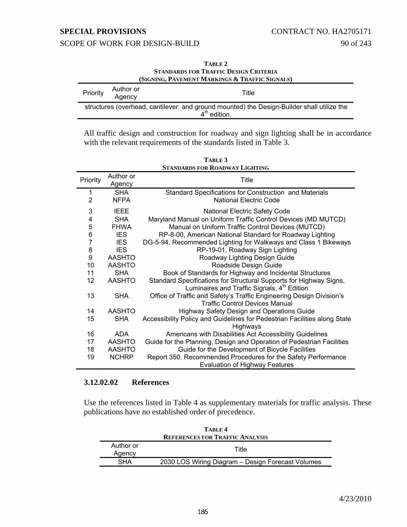
SPECIAL PROVISIONS CONTRACT NO. HA2705171 SCOPE OF WORK FOR DESIGN-BUILD 90 of 243
4/23/2010
TABLE 2 STANDARDS FOR TRAFFIC DESIGN CRITERIA
(SIGNING, PAVEMENT MARKINGS & TRAFFIC SIGNALS)
Priority Author or Agency Title
structures (overhead, cantilever, and ground mounted) the Design-Builder shall utilize the 4th edition.
All traffic design and construction for roadway and sign lighting shall be in accordance with the relevant requirements of the standards listed in Table 3.
TABLE 3
STANDARDS FOR ROADWAY LIGHTING
Priority Author or Agency Title
1 SHA Standard Specifications for Construction and Materials 2 NFPA National Electric Code
3 IEEE National Electric Safety Code 4 SHA Maryland Manual on Uniform Traffic Control Devices (MD MUTCD) 5 FHWA Manual on Uniform Traffic Control Devices (MUTCD) 6 IES RP-8-00, American National Standard for Roadway Lighting 7 IES DG-5-94, Recommended Lighting for Walkways and Class 1 Bikeways 8 IES RP-19-01, Roadway Sign Lighting 9 AASHTO Roadway Lighting Design Guide 10 AASHTO Roadside Design Guide 11 SHA Book of Standards for Highway and Incidental Structures 12 AASHTO Standard Specifications for Structural Supports for Highway Signs,
Luminaires and Traffic Signals, 4th Edition 13 SHA Office of Traffic and Safety’s Traffic Engineering Design Division’s
Traffic Control Devices Manual 14 AASHTO Highway Safety Design and Operations Guide 15 SHA Accessibility Policy and Guidelines for Pedestrian Facilities along State
Highways 16 ADA Americans with Disabilities Act Accessibility Guidelines 17 AASHTO Guide for the Planning, Design and Operation of Pedestrian Facilities 18 AASHTO Guide for the Development of Bicycle Facilities 19 NCHRP Report 350. Recommended Procedures for the Safety Performance
Evaluation of Highway Features
3.12.02.02 References Use the references listed in Table 4 as supplementary materials for traffic analysis. These publications have no established order of precedence.
TABLE 4
REFERENCES FOR TRAFFIC ANALYSIS Author or Agency Title
SHA 2030 LOS Wiring Diagram – Design Forecast Volumes

SPECIAL PROVISIONS CONTRACT NO. HA2705171 SCOPE OF WORK FOR DESIGN-BUILD 91 of 243
4/23/2010
Use the references listed in Table 5 as supplementary materials for the design of signing, pavement markings, and traffic signals. These publications have no established order of precedence.

SPECIAL PROVISIONS CONTRACT NO. HA2705171 SCOPE OF WORK FOR DESIGN-BUILD 92 of 243
4/23/2010
TABLE 5
REFERENCES FOR TRAFFIC DESIGN CRITERIA (SIGNING, PAVEMENT MARKINGS & TRAFFIC SIGNALS)
Author or Agency Title
KDOT Kansas Roundabout Guide – A Supplement to FHWA’s Roundabouts: An Information Guide
FHWA FHWA Roundabouts: An Informational Guide 2000 FHWA-RD-00-067
TRB Transportation Research Board’s Accessible Pedestrian Signals Synthesis and Guide to Best
Practices
3.12.03 Coordination with Other Contracts The Design-Builder shall coordinate the design and construction of all traffic control devices for the Project with those required for other SHA, Harford County, City of Aberdeen, and local jurisdiction Projects.
3.12.04 Traffic Operational Analysis – Procedures and Application
3.12.04.01 Approved Analysis Techniques and Software
3.12.04.01.01 Highway Capacity Manual and Software – Latest Version All freeway mainlines, ramp junctions (merge and diverge locations), and weaving sections shall be analyzed using the Highway Capacity Manual and Software (latest version). The Design-Builder shall provide a summary of results on a line diagram of the proposed roadway configurations, including both the level of service and the volume-to-capacity (V/C) ratio as appropriate. The Design-Builder shall also provide all calculation files on a CD to support the summary of results. 3.12.04.01.02 Synchro and SimTraffic – Latest Version
For corridors with multiple intersections, or for individual signalized intersections, the Design-Builder shall use Synchro and SimTraffic to analyze corridor and individual intersection operations. The Design-Builder’s timing plans shall consider corridor-wide cycle lengths and appropriate offsets. The Design-Builder shall provide all calculation files on a CD to support the summary of results.

SPECIAL PROVISIONS CONTRACT NO. HA2705171 SCOPE OF WORK FOR DESIGN-BUILD 93 of 243
4/23/2010
3.12.04.01.03 CORSIM/VISSIM – Latest Version
For freeway and arterial operations, the Design-Builder shall use CORSIM or VISSIM to analyze operations. This shall be in addition to the Highway Capacity Manual and Software, and Synchro/SimTraffic requirements listed above. Results will be considered by the Administration in conjunction with the above when assessing design alternatives proposed by the Design-Builder. 3.12.04.01.04 SIDRA – Latest Version
For all roundabouts proposed by the Design-Builder, operational analyses shall be completed with SIDRA, with the Environmental Factor set to 1.2, as recommended by the software manufacturer when analyzing roundabouts in the U.S. The volumes should also be checked against the capacity thresholds outlined in NCHRP 3-65, Applying Roundabouts in the United States. The results shall demonstrate that the roundabout operation will be no worse than the corresponding intersection operations proposed in the RFP. An analysis that results in a degree of saturation of 0.85 or more on any movement shall be considered a Level of Service F condition. 3.12.04.01.05 Queuing Analysis Technique
To determine the appropriate length of left and right turn bays, the Design-Builder shall calculate the queue length for both the through lane/s and the turn lane/s for the proposed design and each MOT phase of operation using the Administration's Queuing Analysis methodology, as outlined in the Administration's Procedures for Intersections memorandum, latest version. The Design-Builder shall also analyze all ramps such that queues do not extend from the ramp terminus to either US 40 or MD 715 mainline. The Design-Builder shall provide calculations that the sight distance will be adequate for vehicles exiting and entering either US 40 or MD 715 mainline at highway speeds to see the back of the queue and decelerate to a stop condition. The queuing analysis shall be supplemented with simulation analysis if the queue length exceeds 85% of the design storage length or is the v/c ratio exceeds 0.85. 3.12.04.01.06 Operational Assessment of Design Alternative/s It shall be the Design-Builder’s responsibility to perform traffic analyses for each MOT phase using the tools and techniques listed above, as appropriate.
If a change is proposed to the general geometric layout shown in the concept plans included in the RFP/IFB, the Design-Builder shall use the 2030 Build Volumes to develop and test the final design plans. All modifications to the

SPECIAL PROVISIONS CONTRACT NO. HA2705171 SCOPE OF WORK FOR DESIGN-BUILD 94 of 243
4/23/2010
general geometric concept shall provide traffic operations equal to or exceeding the operational analysis completed by the Administration for the original design. The Design-Builder shall also provide a corridor analysis using CORSIM and Synchro to review corridor-wide operations for the proposed change. Where interpretation of the traffic analyses is required (i.e. if a change results in some improvements and some decreases in operations), it will be the Administration’s determination whether the change is acceptable. In addition to the above, the Design-Builder shall also be responsible for reviewing the anticipated 2030 operational and design speed(s) for each segment of roadway and shall provide the operational and design speed differentials between adjacent lanes (i.e. mainline versus merging ramp) in tabular form for review by the Administration. 3.12.04.01.07 Signal Warrant Analysis Traffic analyses for the general geometric layout shown in the concept plans included in the RFP/IFB have been completed and approved by the Administration. The following intersections require signalization based on the concept plans included in the RFP/IFB:
• MD 715 and Ramps 4 and 6 • Modification of the existing signal at MD 715 and Old Philadelphia Road • US 40 at Ramp 7 (temporary to facilitate construction of Ramp 6)
The Design-Builder shall be responsible for performing an evaluation to determine if signalization is appropriate, based on the MD MUTCD, if the Design-Builder proposes modifications to the general geometric layout shown in the concept plans included in this RFP/IFB. Study findings shall be presented in a report which outlines the warrants evaluated, consideration given to safety, operations, delay, and available gaps in traffic resulting from adjacent signalized intersection. Recommendations shall also be included in the report and shall be attached to the Administration’s Office of Traffic and Safety’s Traffic Control Device Design Request Form, as discussed in the “Preparation and Submittal of Administration’s Office of Traffic and Safety’s Traffic Control Device Design Request Form.” All signal warrant evaluations shall be presented and reviewed prior to final design.
3.12.04.02 Preparation and Submittal of Administration’s Office of Traffic and Safety’s Traffic Control Device Request Design Request Form
Traffic Control Device Design Request Forms have been prepared by the Administration based on the general geometric layout shown in the concept plans included in the RFP/IFB. If the Design-Builder proposes modifications to the general geometric concept that would necessitate a change in the operation of traffic control devices, the Design-Builder shall submit the Administration’s Office of Traffic and Safety’s Traffic Control

SPECIAL PROVISIONS CONTRACT NO. HA2705171 SCOPE OF WORK FOR DESIGN-BUILD 95 of 243
4/23/2010
Device Request Design Request Form to the Administration with accompanying traffic operational analysis/documentation and signal warrant analysis. The following are changes to traffic control devices that warrant the preparation of the Traffic Control Device Design Request Form:
A. New traffic signals, intersection control beacons, or hazard identification beacons; B. Removal of existing traffic signals, intersection control beacons, or hazard
identification beacons; C. Functional change of any existing signal, such as adding or changing signal
phases; D. Any type of signal preemption or priority; E. Any existing traffic signal modification such as relocating poles, strobes, optically
programmed heads, LED heads, back plates, adding or shifting signal heads, addition of accessible pedestrian signals and countdown pedestrian signals, etc.;
F. Additional signal detection or changes to existing detection; G. Signal detector repair/replacement as part of a reconstruction or resurfacing effort; H. All highway lighting or major change to an existing lighting system; I. All new overhead or cantilevered sign structures or modifications to existing; J. All revisions to the legend of major guide signs; and K. Signing and pavement markings for new facilities and modifications to existing
facilities.
To initiate the Definitive Design process, the Design-Builder shall prepare each Design Request Form in accordance with the procedures outlined in the Administration’s Design Request Form Instructions and Guidelines, and shall submit the Design Request Form and supporting traffic studies and documentation to the Administration. All Design Request Forms will be submitted to the Administration for consultation and written comment, prior to the Design-Builder proceeding with the design, installation, or modification to any traffic control device.
3.12.05 Signing
3.12.05.01 Signing Functional Operation Requirements 3.12.05.01.01 Temporary Signing Requirements
Temporary signing for this Project shall include the design and installation of temporary traffic control signs, as per Category 1 of the Administration’s Book of Standards, and use of temporary guide signing (including the installation of new guide signs and/or the modification of existing guide signs). Temporary signing shall be shown on the Traffic Control Plans (TCP). For more information on the requirements for temporary signing, refer to section 3.16 of the performance specifications.

SPECIAL PROVISIONS CONTRACT NO. HA2705171 SCOPE OF WORK FOR DESIGN-BUILD 96 of 243
4/23/2010
3.12.05.01.02 Permanent Guide Signing Requirements
Permanent guide signing for this Project shall have the following functional requirements:
• Signing at the interchange of US 40 with MD 715 shall be based on the
Intermediate interchange classification on the US 40 approaches and the Minor interchange classification for the MD 715 approach, as defined in the MD MUTCD, Section 2E.29;
• Advance guide signing shall be provided along both eastbound and westbound US 40, to include a ½ mile and 1 mile sign. Supplemental sign messages shall be included to direct visitors and deliveries to APG to use the MD 715 exit and to direct motorists to Hickory Drive/Industrial Center;
• Advance guide signing shall be provided along northbound MD 715, to include a ¼ or ½ mile sign;
• Exit direction guide signs and exit gore signs shall be provided along all approaches to the interchange;
• Supplemental guide signs shall be provided along both eastbound and westbound US 40 for APG deliveries; and
• Guide signs shall be provided along Ramp 6 directing motorists to APG and Hickory Drive destinations.
Route marker, regulatory, and warning signs shall be provided based on MD MUTCD requirements and the Administration’s Traffic Control Devices Design Manual.
3.12.05.02 Design and Construction Requirements All temporary signing shall be shown on the Traffic Control Plans (TCP). The Design-Builder shall design and install temporary signing to provide motorist guidance throughout and within the Project limits All proposed signing shall be shown on a definitive design signing roll plan and reviewed by the Administration prior to advancing the design. The Design-Builder shall be responsible for the design and construction of all signing.
3.12.05.02.01 Definitive Design Signing Roll Plan The Design-Builder shall prepare a Definitive Design Signing Roll Plan and present the plan at a review meeting with the Administration. The roll plan shall include proposed sign locations (overhead, cantilever, ground mounted, etc.) and messages for all guide, supplemental, route marker, regulatory, and warning signs. All existing signs to be removed or relocated shall also be shown along with the proposed locations for the relocated signs. The Design-Builder shall not relocate existing overhead or cantilever sign structures. The roll plan shall

SPECIAL PROVISIONS CONTRACT NO. HA2705171 SCOPE OF WORK FOR DESIGN-BUILD 97 of 243
4/23/2010
display signing for US 40, MD 715, Old Philadelphia Road, and Hickory Drive, as well as for the cross-street streets, frontage roads, and any other roadways that contain signing that is affected by the Project. The Design-Builder shall also provide for the modification or removal of any signage outside the limits of the Project that is no longer appropriate or pertinent as a result of changes associated with this Project. The signage shall be removed or modified regardless of whether it falls within or outside the limits of construction along the mainline and cross-street approach roadways. Existing sign modifications shall conform to the latest applicable standards and may include sign overlays, replacement of the entire sign panel, or complete sign structure replacement. The use of full sign overlays is not permitted. The Design-Builder shall be fully responsible for replacing existing sign structures with new structures on new foundations as required to accommodate new and/or modified signs. The Design-Builder shall provide signing for roadways where existing access has been modified. The signing modifications due to the access modifications shall be shown on the definitive plan. The plan shall also denote which agency is responsible for ownership and maintenance of each sign and structure (i.e. SHA or local jurisdiction). The definitive plan features shall include, but are not limited to, the existing and proposed roadway alignments, right-of-way, utilities, baseline of construction (including stationing), and existing topography at the tie-in points of the roadway limits of work. The proposed pavement markings shall also be shown on the definitive plan. 3.12.05.02.02 Plan Sheet Requirements Once the roll plan is reviewed by the Administration, the Design-Builder shall prepare signing plans at a scale of 1”=50’ or equal to the roadway plans. Plans shall show the proposed message, MD MUTCD or MUTCD sign designation (if applicable), size and location of all guide, supplemental, route marker assemblies, regulatory, and warning signing. These plans shall also show the location, messages and sizes of all existing signs. All existing signs to be removed or relocated shall also be shown along with the proposed locations for the relocated signs. The plans shall also include the location and type of delineation devices (including pavement markings). The owner of each sign/structure shall be clearly noted on the plan sheets. All proposed guide, supplemental and non-standard signs shall be detailed on an SN-3 (Sign Fabrication) detail sheet. The plan set shall include SHA’s latest SN-1 sheet (General Notes and Proposals). The Design-Builder shall be responsible for contacting SHA to obtain the latest SN-1 sheet. The SN-4 (Ground Mount Sign Support Details) sheet shall be used for all ground mounted guide or supplemental sign supports. All ground mounted sign supports (steel and wood) shall be detailed on this sheet. The tables on this sheet shall include the Sign Number, Plan Sheet number where the sign is located, the sign size, the post size to be used, if the supports are breakaway or non-breakaway, the support lengths, the lateral clearance code and offset, and the support spacing from left edge of sign. If necessary, the SN-8 (Overhead

SPECIAL PROVISIONS CONTRACT NO. HA2705171 SCOPE OF WORK FOR DESIGN-BUILD 98 of 243
4/23/2010
Structures) and the SN-9 (Cantilever Structures) sheets shall also be included in the plan set. The SN-11 (Signing and Marking Quantities) sheet may be included which summarizes the quantities and materials in table format being used for this Project. If the SN-11 sheet is submitted, every sign location shall have a separate line. 3.12.05.02.03 Design of Sign Locations
The Design-Builder shall design, fabricate and install all the overhead and ground mounted signs shown on the definitive plan, within 25-feet of the location shown on the definitive plan or as approved otherwise by the Administration. 800 foot spacing shall be maintained between overhead signs and traffic signals. For signing along US 40, MD 715 and cross-streets, all guide signs, supplemental guide signs, and any overhead or cantilever structures shall be installed such that 800 foot spacing is maintained, unless approved by the Administration. It is the Administration’s intent to have the signs spaced at 800 foot intervals so that future signing can be accommodated and the 800 foot spacing is maintained. Overhead and cantilever sign structures installed upstream of bridges crossing over the traveled roadway shall be constructed with at least 300 feet between the sign structure and the bridge, unless precluded by the MD MUTCD or Administration standards. Overhead and cantilever sign structures installed downstream of bridges crossing over the traveled roadway shall be constructed at least 800 feet from the bridge. To the extent possible, the Design-Builder shall provide minimum 200 foot spacing between ground-mounted signs. The Design-Builder shall coordinate the proposed sign locations with all proposed landscaping, utility, hydraulic, lighting, and all other roadside features to assure proper clearances, lighting levels, and adequate sight distance. 3.12.05.02.04 Sign Design and Construction Requirements The Design-Builder shall design, fabricate, and install all guide, supplemental, route marker assemblies, regulatory and warning required for this Project, including approaches outside Project limits. The Design-Builder shall modify all existing signs requiring message modification, including approaches outside Project limits.
The messages, fonts, font sizes, arrows, shields, colors, borders, and type of supports for the overhead and ground mounted signs shall be designed and constructed according to the MD MUTCD. The Clearview font shall be utilized for all positive contrast guide signs. Positive contrast guide signs are signs that utilize white text/copy on a dark colored background (i.e. green, blue, black, brown, etc.)
All Advisory, Regulatory, and Warning Signs and route marker assemblies installed along US 40 shall be expressway size. All Advisory, Regulatory, and

SPECIAL PROVISIONS CONTRACT NO. HA2705171 SCOPE OF WORK FOR DESIGN-BUILD 99 of 243
4/23/2010
Warning Signs and route marker assemblies installed along all other roadways shall be standard size. The sizes of the signs shall adhere to the latest edition of the Maryland State Highway Standard Sign Book and the FHWA Standard Highway Signs Book. Guide signs indicating left or exit only movements entering or exiting freeways or expressways shall have the action message (i.e. NEXT LEFT, LEFT LANE, EXIT ONLY, etc.) in black legend on fluorescent yellow background. Fluorescent yellow background sheeting shall be used for all yellow traffic signs. When a sign contains more than one background color, the signs shall have two separate borders corresponding to each background color where the background colors meet. If the background colors utilize the same border color, then only one border is necessary where the background colors meet.
All signs greater than 4’ x 8’ shall be manufactured using extruded aluminum sign material. All new signs for this Project shall be constructed with non-reflective (black copy and background) or retroflective (all other colors) sheeting background and copy. The retroflective sheeting for sign copy shall comply with Section 950.03.07 of the Administration’s Standard Specification for Construction and Materials. All retroflective sheeting for sign backgrounds except for fluorescent yellow and fluorescent yellow-green shall comply with Section 950.03.08 of the Administration’s Standard Specification for Construction and Materials. All fluorescent yellow and fluorescent yellow-green sign backgrounds shall comply with Section 950.03.07 of the Administration’s Standard Specification for Construction and Materials. 3.12.05.02.05 Sign Support Design and Construction All overhead and cantilever sign structures installed under this Project shall be located at a minimum of 50 feet from any roadway lighting.
For each overhead or cantilever structure location, the Design-Builder shall draw the sign panel(s) and the sign structure on the corresponding completed cross-section. The proper vertical and horizontal clearances, sign sizes and sign structure offsets, number of lanes, and lane widths shall be labeled on the cross-sections. The Design-Builder shall check the cross-sections and profiles at all overhead sign locations and make adjustments as necessary to provide adequate sight distances and ground clearances to the bottom of the luminaire supports. Using the sign structure cross-section, the Design-Builder shall correctly fill out the Administration’s sign structure input sheet for each overhead/cantilever sign structure. The sign structure input sheet and associated cross section shall be submitted during the definitive design for Administration review and written comment. Comments on the input sheets will be provided within 21 calendar days and returned to the Design-Builder for revisions, if needed. Once comments to input sheets have been satisfactorily resolved, the Design-Builder shall develop

SPECIAL PROVISIONS CONTRACT NO. HA2705171 SCOPE OF WORK FOR DESIGN-BUILD 100 of 243
4/23/2010
the standard SN-8 and SN-9 sheets for the sign structures. The Administration will provide current SN-8 and SN-9 sheets upon request.
For signs using Breakaway wood supports, Non-Breakaway wood supports, or Non-Breakaway steel supports, the Design-Builder shall utilize the support selection charts provided in the Administration’s Traffic Control Device Design manual. For sign structures (Overhead, Cantilever, and Breakaway Steel Ground Mounted) the Design-Builder shall utilize the 4th edition of AASHTO’s Standard Specifications for Structural Supports for Highway Signs, Luminaires, and Traffic Signals. The wind speed to be used in design shall be 100 mph. The structure design life shall be a 10 year recurrence interval for ground mounted signs using breakaway steel supports. For signs using breakaway steel supports, the Design-Builder shall utilize the design assistance CD provided by the manufacturer of the breakaway system and follow the ground mounted steel post breakaway system selection process provided by the Administration. All posts except for W6X9 wide flange steel I-beams shall have at least 7 foot clear distance between adjacent posts. All wide flange steel I-beam sign supports shall utilize ASTM A709 Grade 36 steel. All square steel posts shall utilize ASTM A500 Grade B structural tubing.
Sheet aluminum signs on State-maintained roadways shall be mounted on wood supports. Sheet aluminum signs on all other roadways may be mounted on either wood supports or square tubular steel posts. Signs over 32 square feet shall be installed on steel posts, unless otherwise noted by the Administration for a particular sign. Additionally, if the signs are installed at a location where steel posts are required, then extruded aluminum sign material shall be used. All exit gore signs shall be placed on steel supports.
No signs or sign structures will be allowed on bridge overpass structures. No signs shall be banded to utility poles, street lighting poles, and overhead or cantilever sign structure uprights without OOTS approval.
Traffic barriers shall be provided for protecting all non-breakaway supports within the clear zone and for new structures within as well as outside the limits of work. Signs shall be placed outside the clear zone wherever possible.
The Design-Builder will be responsible for locating and marking all underground and overhead utilities prior to any signing work beginning. 3.12.05.02.06 Modification to Existing Overhead Signs The Administration will provide the Design-Builder with blank ‘Structure Verification for Adding, Deleting or Modifying Signs on Existing Structures’ sheets. Any modifications to the existing overhead sign structures, including replacement of sign panels, shall be presented to the Administration for review

SPECIAL PROVISIONS CONTRACT NO. HA2705171 SCOPE OF WORK FOR DESIGN-BUILD 101 of 243
4/23/2010
and written comment. Review and written comments, if necessary, will be provided within 21 calendar days. Upon satisfactory resolution to comments, the Design-Builder shall draft the plans and/or notes using CADD for review with the Administration. Modifications to existing overhead signs may require new sign structures. The Design-Builder is fully responsible for determining when new sign structures are required, and for the design and construction of all new sign structures and the removal of existing sign structures no longer needed. 3.12.05.02.07 Sign Lighting The Design-Builder shall provide sign lighting maintenance systems for all new and existing overhead and cantilever sign structures within the Project limits and/or modified by the Project in accordance with the lighting section of this RFP. All sign lighting shall be on dedicated circuits. The sign lighting design shall be shown on the roadway lighting plans. All overhead and cantilever sign structures shall be illuminated.
3.12.05.03 Submittals The Design-Builder shall submit the following items prior to the Final Design Signing Review:
A) Definitive Design Signing Roll Plan;
B) For all proposed sign structures, the Administration’s sign structure input sheet for each overhead/cantilever sign structure along with the associated cross-sections; and
C) For all existing sign structures, the Administration’s ‘Structure Verification for Adding, Deleting or Modifying Signs on Existing Structures’ sheets.
3.12.06 Pavement Markings
3.12.06.01 Design and Construction Requirements All temporary pavement markings shall be shown on the Traffic Control Plans (TCP). Temporary pavement markings shall be designed and installed to provide motorist guidance throughout and within the Project limits. Temporary pavement marking tape shall be used on all concrete surfaces. Temporary tape or paint are permitted on asphalt surfaces. All proposed permanent pavement markings shall be shown on definitive plans for signing and reviewed by the Administration prior to advancing the design.

SPECIAL PROVISIONS CONTRACT NO. HA2705171 SCOPE OF WORK FOR DESIGN-BUILD 102 of 243
4/23/2010
All proposed pavement marking shall be shown on the same plan sheets as the signs. All single longitudinal lines shall be 5 inches wide, and all double width lines shall be 10 inches wide. The plans are to show color, size, location, and material type for markings within the limits of work. The final design marking plans shall be indicated on the signing plan with the same scale as the signing plan. The lanes shall be dimensioned based on the typical sections for the Project. Dimensions shall be included for each change in the roadway typical. The plan shall also clearly define locations where pavement markings change color, width, or material. The Design-Build Team shall be responsible for the design and construction of all pavement markings. For all final pavement marking lane lines, including parallel, acceleration/deceleration lanes for ramps, intersection auxiliary lanes, and Raised Pavement Markers (RPMS), the following Pavement Marking Material Table shall be adhered to:
Pavement Marking Abbreviations
RPMs – Snowplowable Raised Pavement Markers PPPRP – Permanent Patterned Preformed Retro-Reflective Pavement Markings
Durable Markings – Includes thermoplastics, patterned preformed thermoplastics (wet tape), or epoxy. All durable markings shall demonstrate wet retro reflective properties when tested in accordance with ASTM #E 2177-01 (Test Method for Measuring the Coefficient of Retroreflected Luminance (RL) of Pavement Markings in a Standard Condition of Wetness).
Paint – Whenever paint is listed as an application, the 50/50 blend of large and standard glass beads is required. Pavement marking types and locations shall be in accordance with Table 6 – Roadway Pavement Markings.
Table 6
Roadway Pavement Markings PAVEMENT MARKING MATERIAL TABLE
CATEGORY ROADWAY TYPE LINE STRIPING MATERIAL Center
Lines Lane Lines Edge Lines
Portland Cement Concrete (PCC) (Including Bridge Decks) 1 Highway (other than
Interstate/Freeway) AADT < 50,000
PPPRP with
RPM’s
Contrast PPPRP with
RPM’s PPPRP
HOT MIX ASPHALT (HMA) 1 Multi-lane or Divided Highway
(other than Interstate/Freeway)
Durable with
RPM’s
Durable with RPM’s Durable

SPECIAL PROVISIONS CONTRACT NO. HA2705171 SCOPE OF WORK FOR DESIGN-BUILD 103 of 243
4/23/2010
PAVEMENT MARKING MATERIAL TABLE CATEGORY ROADWAY TYPE LINE STRIPING MATERIAL
Center Lines Lane Lines Edge Lines
AADT < 50,000 2 2-Lane 2-Way Roadway
AADT ≥ 30,000 Durable ------ Durable
3 2-Lane 2-Way Roadway AADT < 30,000 Paint ------ Paint
For pavement markings along ramps, the Design-Builder shall utilize the highest category markings of the intersecting roadways, with 1 being assigned the highest category marking and 3 assigned the lowest. All transverse pavement markings (i.e. yield symbols (shark’s teeth), crosswalks, stop lines), as well as all arrows, symbols, and letters shall be heat applied permanent preformed thermoplastic.
All permanent pavement markings installed on the Project shall be listed on the Administration’s List of Qualified Permanent Pavement Markings, unless submitted and approved through the Administration’s Maryland Product Evaluation List (MPEL) program.
3.12.07 Traffic Signals
3.12.07.01 Traffic Signal Functional Operation Requirements Based on the general geometric layout shown in the concept plans included in the RFP, Design Request Forms have been completed and approved for permanent traffic signals at the intersections of MD 715 with Ramps 4 & 6 and Old Philadelphia Road and for a temporary traffic signal at a temporary intersection of US 40 with Ramp 7 by the Administration. The temporary and permanent traffic signals shall be designed as per the requirements outlined in the Design Request Forms, and as noted below (if the general geometric layout remains the same at the following intersections): MD 715 at Ramps 4 and 6
• New traffic signal installation • Interconnected hardware system with signal at intersection of MD 715 with Old
Philadelphia Road • Signalization of triple right turn from Ramp 6 onto SB MD 715 with NO TURN
ON RED • Typical signing, marking, and lighting • Typical signal design layout, features, and materials • Install phone line for video detection

SPECIAL PROVISIONS CONTRACT NO. HA2705171 SCOPE OF WORK FOR DESIGN-BUILD 104 of 243
4/23/2010
US 40 at Temporary Spur to Ramp 7 • Temporary traffic signal installation (to be removed AFTER signal on MD 715
at Ramps 4 and 6 is fully operational) • 2-phase signal operation
o Westbound US 40 through movement o Eastbound US 40 left turning movement
• Eastbound US 40 through traffic NOT controlled by traffic signal • Westbound US 40 right turning traffic onto Ramp 7 NOT controller by traffic
signal. Yield condition to be provided for Ramp 7 traffic at Temporary Spur 7 • Typical temporary signing, marking, and lighting • Typical temporary signal design layout, features, and materials • Install phone line for video detection
MD 715 at Old Philadelphia Road.
• Traffic signal reconstruction • Interconnected hardware system with signal at intersection of MD 715 with
Ramps 4 and 6 • Exclusive left turn phases for NB and SB MD 715 • Typical signing, marking, and lighting • Typical signal design layout, features, and materials • Install two phone lines for video detection and system controller • Install master controller
MD 715 at Hickory Drive/Ramp 7 Intersection Control Beacon (ICB)
• ICB reconstruction • Replace advanced hazard identification beacon (HIB) along Ramp 7 approach to
intersection • Typical signing, marking, and intersection lighting • Typical ICB design layout, features, and materials
3.12.07.02 Design and Construction Requirements
3.12.07.02.01 Definitive Design Traffic Signal Roll Plan The Design-Builder shall prepare a Definitive Design in the form of a traffic signal location roll plan for Administration review that includes all existing signal equipment and interconnect, and displays all proposed signal equipment and interconnect within the Project. The plan shall also display all existing and proposed crosswalks within the Project. Any temporary Maintenance of Traffic (MOT) Signal Plan(s), and signal plans showing the phasing of signal construction, shall also be presented at this time.

SPECIAL PROVISIONS CONTRACT NO. HA2705171 SCOPE OF WORK FOR DESIGN-BUILD 105 of 243
4/23/2010
3.12.07.02.02 Plan Sheet Requirements The Design-Builder shall prepare Traffic Signal plans to address any new traffic signals, temporary traffic signals, or modifications to existing traffic signals that are required. The traffic signals shall be designed as per the approved Design Request and as specified in section 3.12.07.01 Traffic Signal Functional Operation Requirements for each intersection. All traffic signal plans shall be drawn in accordance with the Administration’s Traffic Control Device design manual, CADD standard requirements, and the MD MUTCD. Existing traffic signal operation and detection shall be maintained during all phases of the roadway construction and all stages of Maintenance of Traffic. Design and construction of all permanent traffic signals shall use mast arm signal poles unless otherwise noted by the Administration. The use of diagonal single mast arms is not permitted, unless approved by the Administration. Design and construction of temporary traffic signals may use strain poles or wood poles (if the estimated duration of signal operation is less than one year) with span wires. Lighting shall be provided on signal poles on the far side of the mainline approaches to the intersection wherever feasible, and shall be coordinated with adjacent existing and/or proposed roadway and/or sign lighting. Electrical cables for intersection lighting shall not pass through the signal cabinet. 3.12.07.02.03 Interconnect Plans The Design-Builder shall prepare traffic signal interconnect plans as indicated in the Design Request and section 3.12.07.01 Traffic Signal Functional Operation Requirements. Interconnect plans shall be drawn at a scale of 1”=50’. The Design-Builder shall obtain all existing interconnect information and all existing interconnected signals shall remain connected under the final design. Interconnect plans shall include controller cabinet locations, conduits, handholes, sampling stations, wiring diagram, cables, construction details, and equipment list in accordance with the Administration’s design and CADD requirements. All existing traffic signal interconnect shall be maintained throughout construction, which may require relocation or temporary interconnect. Along any run of interconnect, there shall be no net increase in splice points. The Design-Builder shall utilize at least twelve-pair communication cable for all proposed interconnect. All impacted or damaged interconnect cables shall be replaced in-kind. Traffic signal interconnect cables shall not utilize conduit or handholes//manholes/junction boxes that contain electrical cables.
SPECIAL PROVISIONS CONTRACT NO. HA2705171 SCOPE OF WORK FOR DESIGN-BUILD 106 of 243
4/23/2010
The Design-Builder shall be responsible for all work and costs associated with maintaining communication cable throughout construction for affected traffic signals. The Design-Builder shall be responsible for utility pole removals required when relocating existing interconnect. All interconnect shall be relocated prior to roadway construction in order to assure that interconnect can be maintained throughout construction. The Design-Builder shall be responsible for relocation of any existing fiber optic cable impacted by construction. The Design-Builder shall coordinate with SHA to facilitate the relocation of existing interconnect and fiber optic cables and equipment. All proposed splices shall occur in signal or splice cabinets. If a section of interconnect run is not long enough to be relocated, the entire section of cable shall be replaced. The Design-Builder shall be responsible for obtaining all permits required for placing interconnect on utility poles and shall be responsible for all associated costs.
3.12.07.02.04 Utility Requirements The Design-Builder shall be responsible for locating and marking all underground and overhead utilities prior to any signal installation work. The Design-Builder shall be responsible for all Work, materials, and costs associated with obtaining power (including coordination with the utility company). Electric costs for maintaining power throughout construction for all traffic signals and other electrical work required for this Project shall be the responsibility of the Administration. The Design-Builder shall be responsible for completing all electrical service application materials necessary for obtaining service from the appropriate power company. All materials shall be submitted to the power company through the Administration. The Design-Builder shall use 200A Metered Service Pedestals (see TYP. 807.07-01 and 807.07-02) at all traffic signal locations, unless otherwise noted by the Administration. The Design-Builder shall install conduit between the metered service pedestal and the nearest handhole (bypassing the signal cabinet) for intersection lighting. The Administration will be responsible for all on-going electric costs of proposed signal equipment after the signals have been Accepted for Maintenance by the Administration. Metered Service Pedestals shall only be used to service traffic signal equipment and related intersection lighting, unless otherwise noted by the Administration. The current party responsible for any existing metered service that needs to be upgraded or replaced will continue to be responsible for all on-going electric costs after the Project is complete. For each location requested, it is the Design-Builder’s responsibility to complete all paperwork, coordinate with the utility company, and schedule all utility connections so as to not adversely affect the project schedule. 3.12.07.02.05 Sight Distance Requirements The Design-Builder shall ensure all traffic signal heads for existing, temporary, and permanent conditions can be seen by all approaching traffic at the required

SPECIAL PROVISIONS CONTRACT NO. HA2705171 SCOPE OF WORK FOR DESIGN-BUILD 107 of 243
4/23/2010
sight distance at all times during and after construction. The Design-Builder shall also provide calculations that the sight distance will be adequate for vehicles approaching signalized intersections to see the back of the queue and decelerate to a stop condition for all approaches to traffic signals under existing, temporary, and permanent conditions. The Design-Builder shall prepare and present sightline plans for all traffic approaches to the Administration for review and written comment. The Design-Builder shall also prepare and submit to the Administration for review and written comment sightline profiles for all overhead signs, bridges, and hazard identification beacons that are on traffic signal approaches. The Design-Builder shall prepare and present to the Administration for review and written comment separate sightline plans and profiles for each MOT phase that has different sightlines approaching a traffic signal. If sight lines do not meet the MD MUTCD requirements, the Design-Builder shall provide a recommendation for meeting the requirements to the Administration, such as red signal ahead warning signs or flashing beacon signs.
3.12.07.02.06 Materials Traffic signals shall be designed and constructed in accordance with the following:
A) Using Video Detection systems for vehicle detection; B) Using passage detection on intersection approaches, as per SHA’s
Traffic Control Devices Design Manual; C) Using base mounted (NEMA size 6) Maryland State Econolite Traffic
Signal Cabinets wired in accordance with Administration specifications for all permanent traffic signals. Pole mounted (NEMW size 5) cabinets may be permitted for use at temporary traffic signals only. All signal cabinets, controllers, and rack mounted modules will be supplied by the Administration. The Design-Builder shall be responsible for delivering the assembled cabinet from the Administration’s Traffic Signal Shop to the site and installing. The Administration will provide final connection of all cables within the cabinet;
D) Wiring required; E) Using Light-Emitting Diode (LED) traffic signal heads and countdown
pedestrian signal heads; F) Using schedule 80 rigid PVC conduit for underground installations; G) Furnishing and installing required signal related signing; and H) All exposed conduit shall be constructed of galvanized rigid steel.

SPECIAL PROVISIONS CONTRACT NO. HA2705171 SCOPE OF WORK FOR DESIGN-BUILD 108 of 243
4/23/2010
3.12.07.03 Temporary Traffic Signals The Design-Builder shall provide temporary traffic signals as required by the traffic control plans and Design Request Forms. It is anticipated that a temporary traffic signal will be required at a temporary intersection of US 40 with Ramp 7 in order to facilitate the construction of Ramp 6 and a Design Request form has been prepared by the Administration for this temporary traffic signal. This temporary traffic signal shall be designed as per the requirements outlined in the Design Request Form and section 3.12.07.01 Traffic Signal Functional Operation Requirements. It is anticipated that this temporary traffic signal will be operational during the construction of Ramp 6 and that all associated signal equipment will be removed after the ultimate signal at the intersection of MD 715 with Ramps 4 and 6 is operational. If the Design-Builder anticipates the need for the installation of any other temporary traffic signals or for a differing operation for a temporary traffic signal at the intersection of US 40 with Ramp 7, the Design-Builder shall perform all studies as necessary for placement of Temporary Traffic signals, complete the Design Request Forms, and present all information to the Administration for review and written comment. 3.12.07.04 Submittals The Design-Builder shall submit the Definitive Design Traffic Signal Roll Plan prior to advancing design to the readiness for construction review. The Design-Builder shall submit the traffic signal roll plan at the same time of submitting the signing roll plan.
3.12.08 Lighting
3.12.08.01 Design and Construction Requirements
For existing lighting, the maximum outage time for luminaires shall be 24 hours unless otherwise approved by the Administration. All proposed and existing luminaires within the Project limits shall be working upon completion of the Project.
All underground lighting conduits shall be schedule 80 rigid PVC conduit. All exposed conduits shall be galvanized rigid steel conduit.
All roadway lighting installed under this Project shall be located a minimum of 50 feet from any overhead or cantilever structure.
All proposed lighting equipment shall be located such that it can be readily maintained by personnel of the maintaining agency. Where possible, the Design-Builder shall locate signal and lighting cabinets in the same quadrant of the interchange. Lighting placed on traffic signal equipment shall be serviced from a metered service pedestal. Each luminaire mounted on a signal structure shall be equipped with a photocell. Power supply for signal structure mounted lighting and the traffic signal may be installed in the same conduit system. Power supply for roadway lighting shall be installed in separate

SPECIAL PROVISIONS CONTRACT NO. HA2705171 SCOPE OF WORK FOR DESIGN-BUILD 109 of 243
4/23/2010
conduits and on independently metered circuits for respective jurisdictional owners.
The Design-Builder shall provide voltage drop calculations for all circuits. The voltage drop for each branch circuit shall not exceed three percent for new circuits and five percent for existing circuits, assuming a cable temperature of 40 degrees Celsius. A minimum of two branch circuits shall be used for each continuous succession of lighting structures. All lighting circuits shall have balanced lighting loads.
Lighting circuits shall be direct-buried duct cable unless under roadway surfaces, in structures, or in locations where protection from surface loading is needed. Two conductor duct cables shall be used for all roadway lighting circuits. Four conductor duct cable is permitted for sign lighting circuits. Only the conductors that serve the lighting structures shall enter the foundation of the lighting structures. All other conductors shall remain un-spliced and bypass the foundation. The Design-Builder shall furnish and install single conductor cables in Schedule 80 rigid PVC conduit under all roadway surfaces. Single conductor cables shall be used any place cables are to be installed in conduit. The Design-Builder shall provide electrical manholes (or vaults) and connector kits to splice the conductors. The Design-Builder shall provide no more than 30 connector kits in each manhole and no more than 50 connector kits in each electrical vault. No in-ground splices of electrical cables shall be permitted for any reason. No electrical handholes/handboxes/manholes shall be placed in drainage ditches. The Design-Builder shall abandon existing conductors between poles that are to be removed. Power supply for lighting (other than that mounted on signal structures) shall be installed in separate conduit (including handboxes, handholes, and manholes) and on independently metered circuits for respective jurisdictional owners. All underground lighting conduits shall be constructed of Schedule 80 rigid PVC conduit. All exposed conduit shall be constructed of galvanized rigid steel.
Any existing lighting structure that is impacted by construction of this Project shall be disconnected, reconnected, and made fully operational by the Design-Builder as part of this Project unless it is being removed. All abandoned cables shall be made safe.
The Design-Builder shall remove existing light poles that are no longer required due to construction of the Project. The equipment shall be the property of the Design-Builder upon removal. The Design-Builder shall notify the owner of the lighting being removed at least two weeks in advance of the scheduled equipment removal. All light poles that are not protected by traffic barrier and are in the clear zone as defined in the AASHTO Roadside Design Guide shall be installed on a breakaway transformer base complying with the Maryland Book of Standards. Light poles shall not be installed in front of traffic barrier.
The lighting system shall utilize cabinets, conduits, and handboxes/manholes/junction boxes separate from the traffic signal equipment.

SPECIAL PROVISIONS CONTRACT NO. HA2705171 SCOPE OF WORK FOR DESIGN-BUILD 110 of 243
4/23/2010
The Design-Builder shall place luminaries approximately one foot over the pavement marking edge line. To avoid foundation conflicts, the luminaire location may be adjusted approximately 3 feet over the pavement marking edge line, subject to review and concurrence by the Administration.
3.12.08.01.01 Definitive Design Lighting Roll Plan A lighting roll plan shall be presented at the definitive review and concurrently with the signing and signal roll plans for review and written comment by the Administration. The lighting roll plans shall include proposed locations for all lights and photometric calculations supporting the light locations. The lighting roll plan shall be submitted to the Administration for consultation and written comment prior to the Design-Builder proceeding with the design, installation, or modification of lighting.
The Design-Builder shall provide spacing computations showing illuminance and veiling luminance calculations, as appropriate. The calculations shall include uniformity ratios (average-to-min and max-to-min), point-by-point computations, and a summary of the minimum and average maintained lighting levels and the critical veiling luminance ratios. The Design-Builder shall apply a light loss factor of 0.64 when computing photometrics. The computations shall use the lamp lumen requirements in Section 950.12.02 of the Administration’s Standard Specifications for Construction and Materials. For lamp types not listed in Section 950.12.02, the Design-Builder shall use the values provided by the manufacturer. The light loss factor and lamp lumens shall be provided with the illuminance and veiling luminance calculations.
The Design-Builder shall design, fabricate, and install all roadway lighting shown on the definitive design plan within 5 feet of the location shown on the definitive design plan or as otherwise approved by the Administration. 3.12.08.01.02 Plan Sheet Requirements
The Design-Builder shall prepare and present lighting plans with a scale appropriate for the Project, generally 1”=50’. Plans shall include existing and proposed geometry, existing and proposed utilities, right-of-way, landscape features, applicable drainage features, ditch lines, applicable structural facilities, and other information required for coordination of utilities. Plans shall show location of new lighting, type and mounting height of poles, type and wattage of luminaires, length of luminaire arms, removal and relocation of existing lighting, conduit, circuit routings, cable types and installation method, manholes/junction boxes, splice locations with appropriate connector kits, ground rod locations, signs to be lit, electrical service locations, and other details pertinent to the construction. The plans shall include standard Administration identifiers for light

SPECIAL PROVISIONS CONTRACT NO. HA2705171 SCOPE OF WORK FOR DESIGN-BUILD 111 of 243
4/23/2010
poles and manholes as well as standard designations for cable sizes. The plans shall include a panel schedule (including pole and base mounted lighting cabinets on metered service pedestals) showing the circuit breaker loads and equipment connected to each circuit breaker. The plan shall include a schedule of light poles, a sign lighting schedule, and a schedule of manholes/junction boxes. Voltage drop calculations shall be provided concurrently with the lighting plan sheets.
3.12.08.01.03 Existing Lighting
All impacted existing roadway lighting shall be replaced by the Design-Builder. Lighting shall incorporate the same luminaire and pole type as on the rest of the roadway in order to maintain consistency.
The Design-Builder shall design and construct the lighting system consistent with operational and engineering requirements of the utility company and owning/maintaining agencies. For locations where luminaires are attached to a utility pole, the Design-Builder (as a part of the utility relocation effort) shall contact the owner of the lighting to coordinate relocation of the light fixture. The Design-Builder is responsible for coordinating agreements between the owner and the utility company.
The Design-Builder shall remove existing light poles that are no longer required due to construction of the Project. The equipment shall be the property of the Design-Builder upon removal. The Design-Builder shall notify the owner of the lighting being removed at least two weeks in advance of scheduled equipment removal.
3.12.08.01.04 Intersection Lighting
All intersections (both signalized and unsignalized) along MD 715 within the project limits shall have intersection lighting. The Design-Builder shall combine intersection lighting with the traffic signal plans whenever possible. All intersection lighting shall be prepared using the Administration’s guidelines for partial intersection/entrance lighting. See ANSI - IESNA RP-8-00, Annex D for the design and photometric (and calculation zone) requirements of intersection lighting. A photometric analysis at each intersection is required as part of the Definitive Design roll plan. 3.12.08.01.05 Sign Lighting
The lighting system shall be installed on a maintenance track system or other system that provides lamp replacement from the shoulder of the road without closing lanes. Signs shall be only lit from beneath the signs. Acceptable lighting shall consist of a long-life system, meeting the following requirements:

SPECIAL PROVISIONS CONTRACT NO. HA2705171 SCOPE OF WORK FOR DESIGN-BUILD 112 of 243
4/23/2010
A) Using Light Emitting Diode (LED) luminaires approved by the Administration;
B) Having a functional life time of at least 100,000 hours, including lamp and ballast;
C) Having < 50% failure of any component at 60,000 hours, including lamps; and
D) Having a lamp lumen depreciation not worse than 70% at 60,000 hours. All sign lighting shall be on dedicated circuits. For each sign structure a minimum of two circuits shall be used. The sign lighting design shall be shown on the roadway lighting plans. The design of luminaires for sign illumination using long-life lighting systems shall be in accordance with OOTS standard lighting charts. All other sign lighting systems shall be designed to provide an average of 20 to 40 foot candles with 6:1 max to min uniformity. Photometric calculations shall be on a 1 foot grid over the entire surface of the sign. All existing sign lighting within Project limits that is impacted by construction activities shall be maintained throughout construction. 3.12.08.01.06 Underpass Lighting The Design-Builder shall provide nighttime underpass lighting as necessary to maintain continuity of roadway lighting and where warranted by governing documents in Table 3 of section 3.12.02.01 References. The underpass lighting shall provide lighting in daytime periods if warranted. The Design-Builder shall provide analysis, including photometric and height to length ratios, at each location, to justify installing or not installing underpass lighting. Areas being evaluated shall be noted on the Definitive Design roll plan. 3.12.08.01.07 Low Level Lighting Partial Interchange Lighting (PIL) Low level partial interchange lighting shall be provided at the interchange of US 40 with MD 715. It shall consist of luminaires located in the general areas where entrance and exit ramps connect with through traffic lanes on a freeway (i.e. lighting between the entry gore and the end of the acceleration ramp or exit gore and the beginning of the deceleration ramp). All deceleration lanes shall be illuminated from the beginning of the deceleration lane (including the taper) or 500 feet upstream of the painted nose (whichever is shorter) to 140 feet beyond the physical gore nose. Light poles shall not be placed inside the gore within 100 feet of the physical gore nose along mainline lanes. Mainline lanes downstream of the exit ramp gores shall be illuminated to 140 feet beyond the physical gore nose. All acceleration lanes shall be illuminated from the physical gore nose to the end of the acceleration lane (including the taper) or 500 feet beyond the painted nose (whichever is shorter). If the requirements for interchange lighting

SPECIAL PROVISIONS CONTRACT NO. HA2705171 SCOPE OF WORK FOR DESIGN-BUILD 113 of 243
4/23/2010
extend beyond the Project Limits, it will be the responsibility of the Design-Builder to design and construct that lighting. The Administration will secure all additional environmental approvals, easements, and/or right-of-way required by the Design-Builder’s approved lighting concept. The Design-Builder shall design and construct lighting that consists of cobrahead luminaires mounted at a maximum of 40 feet above the pavement with Type III full cutoff optics. Non-Interchange Lighting In locations where the Project will impact existing SHA, Harford County, or City of Aberdeen lighting, lighting shall be replaced by the Design-Builder. Lighting shall incorporate the same luminaire and pole type as on the rest of the roadway in order to maintain consistency.
Aberdeen Proving Ground (APG) Lighting The Design-Builder shall provide roadway lighting in the vicinity of the APG gate. This lighting shall provide a minimum of 0.2 fc on the roadway surface and the calculation zone shall extend at least 10 feet on both sides of the relocated APG entrance gate. The Design-Builder shall use the same luminaire and pole type as the existing lighting in this area. This lighting will be owned and maintained by APG completion of this project. The Design-Builder shall also provide intersection lighting at the intersection of MD 715 with the APG Visitor Center driveway. Intersection lighting shall meet all of the requirements outlined in section 3.12.08.01.04 and shall be owned and maintained by APG.
3.12.08.01.07 Leased Lighting
For locations where luminaires are attached to a utility pole, the Design-Builder (as part of the utility relocation effort) shall contact the appropriate agency to coordinate relocation of the light fixture or installation of new light fixtures provided photometric analysis supports the changes. The Administration will be responsible for coordinating agreements with the utility company.
3.12.08.01.08 Temporary Lighting
All existing roadways which have roadway lighting shall remain illuminated at IES minimum levels for the duration of the Project unless approved otherwise by the Administration.
The Design-Builder shall maintain all existing lighting within the Limits of Work shown on the Concept Plans throughout construction. Where temporary lighting is needed to maintain the existing lighting levels in the Project area, the Design-

SPECIAL PROVISIONS CONTRACT NO. HA2705171 SCOPE OF WORK FOR DESIGN-BUILD 114 of 243
4/23/2010
Builder shall install and maintain temporary lighting (cobra heads attached to wood poles). Temporary overhead electrical service is acceptable for non-breakaway poles. The Design-Builder shall remove temporary lighting when no longer needed. The Design-Builder shall be responsible for the power costs of any and all temporary lighting that may be required and it is the Design-Builder’s responsibility to schedule all utility connections. 3.12.08.01.09 Electrical Service for Lighting The Design-Builder shall be responsible for locating and marking all underground and overhead utilities prior to any lighting work beginning. The Design-Builder shall be solely responsible for all Work, and materials, and costs associated with obtaining power (including coordination with the power company). Electric costs for maintaining power throughout construction for all lighting facilities and other electrical work required for this Project shall be the responsibility of the Administration. The Design-Builder shall be responsible for completing all electrical service application materials necessary for obtaining service from the appropriate power companies. All materials shall be submitted to the power company through the Administration. The Design-Builder shall contact all utility companies to fulfill requirements to determine the location of all existing and proposed utilities, obtain power company requirements for service and obtain power company approval for service location(s). For each location requested, it is the Design-Builder’s responsibility to complete all paperwork, coordinate with the utility company, and schedule all utility connections so to not adversely affect the Project schedule.
Lighting systems owned by different jurisdictions shall have separate power sources derived from the utility company. Exceptions shall require written approval and agreement of all jurisdictions involved and will require separate circuits for each jurisdiction’s electrical elements fed from the electrical service equipment.
3.12.08.01.10 Light Pollution
For all proposed roadway lighting, the maximum allowable vertical and horizontal illuminance at residential property lines shall not exceed 0.05 foot-candles (fc). House side shielding shall be provided where necessary to achieve the 0.05 fc horizontal or vertical illuminance requirement. House side shielding shall also be provided with all roadway lighting within 75 feet of a residential structure. All photometric analyses for light trespass at residential property lines shall utilize a light loss factor of 1.00.
3.12.08.02 Submittals The Design-Builder shall submit the Definitive Design Lighting Roll Plan prior to or

SPECIAL PROVISIONS CONTRACT NO. HA2705171 SCOPE OF WORK FOR DESIGN-BUILD 115 of 243
4/23/2010
at the same time of submitting the Definitive Design Signing Roll Plan. 3.12.09 Advisory Speeds The Design-Builder shall be responsible for providing a report to the Administration that documents all advisory speeds. The report shall include an investigation of the horizontal geometrics based on AASHTO roadway design guidelines. The investigation shall define the critical stopping sight distance for each curve. These above values shall be field verified to determine if the actual conditions provide the critical distances required. Pavement conditions of the roadway shall also be noted. Photographs for each curve shall be taken and included in the report. The Design-Builder shall evaluate curves with an electronic accelerometer (CurveRite Model 1100 or approved equivalent). All electronic accelerometer measurements shall follow the manufacturer’s instructions. The field testing shall not exceed the posted regulatory mainline speed limit and shall be stopped if g-force measurements exceed 0.40 g-ft/sec2. The recommended average g-force for determining advisory speeds is 0.28 g-ft/sec2 and the advisory speeds should be posted in 5 MPH increments. 3.12.10 Regulatory Signing The Design-Builder shall be responsible for providing an engineering study to the Administration that documents all regulatory signing (i.e., speed limits, truck restrictions, etc.) installed under this Project. 3.12.11 Traffic Control Device Verification
The Design-Builder shall schedule meetings with the Administration to verify traffic control device work as follows:
A) At the completion of all cabling and wiring and prior to electrical utility service connection; and
B) Prior to traffic control device activation.

SPECIAL PROVISIONS HA2705171 SCOPE OF WORK FOR DESIGN BUILD Page 116 of 243
4/23/2010
TC 3.13 LANDSCAPE AND REFORESTATION DESIGN PERFORMANCE SPECIFICATIONS
3.13.01 Preservation of Trees and Woodlands
The Administration has imposed restrictions on construction activities that increase the removal of existing trees. The Administration will also require that the project design minimize the amount of trees removed and avoid or minimize impacts to existing tree stands and specimen trees through sound tree protection measures in accordance with the requirements of the Administrations 2008 Standard Specifications Section 120-Tree Preservation Area. Impacts to specimen trees, defined as trees having a 30” or greater diameter at breast height (DBH) or trees having a DBH of 75% or greater of the State or County Champion of the species, shall be avoided where feasible.
A. All impacts to individual trees, woods and forest areas occurring as part of this project, including, but not limited to: crown and branch pruning, tree clearing, and root pruning shall be in accordance with the MD Reforestation Law and/or Roadside Tree Law as applicable and Section 120-Tree Preservation Area. Tree removal and tree protection efforts shall be shown on the construction plans.
B. The Design-Build Team shall employ the services of an individual who is an ISA Certified Arborist, MD Licensed Tree Expert, or MD Registered Forester, or Maryland Licensed Landscape Architect, who shall conduct an on-site inspection to determine the presence and location of any specimen or significant trees within the limits of disturbance plus 30 feet beyond the limits of disturbance. Specimen trees are defined as trees with a Diameter at Breast Height (DBH) of 30” or greater or at least 75% of the DBH of the MD State or Champion of the species, whichever DBH measurement is smaller. For the purpose of this contract significant trees are defined as trees 24” or larger DBH.
C. The Design-Build Team shall employ the services of an individual who is an ISA Certified Arborist, MD Licensed Tree Expert to prepare a Tree Impact Avoidance and Minimization Report as described under Deliverables and consistent with the Administrations 2008 Standard Specifications Section 120-Tree Preservation. The Report shall be submitted to the Office of Environmental Design, Landscape Operations Division (OED-LOD) for approval, prior to installation of erosion and sediment controls.
D. The Administration will have obtained a Reforestation Site Review Approval from Maryland Department of Natural Resources Forest Service (MD DNR-FS) for impacts to individual trees and forest areas within the proposed limits of disturbance shown on the Concept Plans prior to issuance of Notice to Proceed. The Design-Build Team shall be responsible for the complete process of preparing and submitting required documentation to OED-LOD for review of conformance with the current MD DNR Reforestation Site Review Approval.
E. In the event that impacts to individual trees and/or forest areas increase beyond limits

SPECIAL PROVISIONS HA2705171 SCOPE OF WORK FOR DESIGN BUILD Page 117 of 243
04/23/2010
approved by MD DNR-FS, The Design-Build Team shall be responsible for the complete process of preparing and submitting required documentation to OED-LOD for modifications to the Reforestation Site Review Approval. OED-LOD will make submittals to MD DNR-FS within seven (7) business days of receipt, provided the submittal is acceptable to OED-LOD. The Design-Build Team shall be responsible for addressing comments from MD DNR-FS and amending the Reforestation Site Review Submittal if/as required by MD DNR-FS for approval.
F. The Design-Builder shall be in possession of a valid Roadside Tree Permit or Reforestation Site Review Approval for all applicable tree and forest impacts within the project limits be prior to installation of erosion and sediment control measures, tree clearing, demolition or construction work onsite. Delays in obtaining a modified Roadside Tree Permit or Reforestation Site Review Approval per 3.13.01(e) are the responsibility of the Design-Builder. Tree and forest mitigation plantings shall be coordinated with and approved by OED-LOD and OED-LAD.
G. The Design-Build Team is responsible for maximizing on-site individual tree and/or
reforestation mitigation for impacts to trees and/or forest areas per the Roadside Tree Law or MD Reforestation Law as applicable. Mitigation plantings for individual tree and/or forest removal shall be provided within the project limits as per the following:
3.13.01.01 Roadside Tree Law Mitigation Plantings (for trees removed under a Roadside Tree Permit)
a) A mix of Native evergreen, shade, and ornamental tree species of the Coastal Plain region of Maryland shall be specified as appropriate to site conditions.
b) Use of non-invasive non-native tree species, or cultivars of native species maybe approved at the discretion of the Office of Environmental Design, Landscape Architecture Division (OED-LAD). The Administration will reject unacceptable species.
c) The rate of replacement for individual trees shall be as listed follows:
1. For each tree removed having a DBH (diameter at breast height) of up to 12”, specify (1) of the following:
• 1.75” caliper single-stemmed deciduous tree • 6’ height (multi-stemmed deciduous tree) • 6’ height evergreen tree.
2. For each tree removed having a DBH greater than 12” up to 24”, provide any combination of two (2) of the following:
• 1.75” caliper single-stemmed deciduous tree • 6’ height (multi-stemmed deciduous tree) • 6’ height evergreen tree.
3. For each tree removed having a DBH of greater than 24”, provide any combination of three (3) of the following:
1. 1.75” caliper single-stemmed deciduous tree

SPECIAL PROVISIONS HA2705171 SCOPE OF WORK FOR DESIGN BUILD Page 118 of 243
04/23/2010
2. 6’ height (multi-stemmed deciduous tree) 3. 6’ height evergreen tree
4. Where preservation of specimen trees is infeasible, additional tree plantings may be required at the discretion of DNR.
3.13.01.02 Maryland Reforestation Law Mitigation Plantings:
a) A mix of native evergreen and deciduous tree species and shrubs of the Coastal Plain region of Maryland shall be specified as appropriate to site conditions.
b) Use of cultivars of native species may be approved at the discretion of OED-LAD. The Administration will reject unacceptable species.
c) Reforestation areas adjacent to existing forest to remain must be at least ¼ acre in size. Combined forest area width (existing and reforestation) must be at least 50’ wide.
d) Reforestation areas not adjacent to existing forest must be at least one half (1/2) acre in size and at least 50’ wide.
e) Reforestation plantings shall be provided at a mitigation ratio of 1:1. In other words, one (1) acre of reforestation plantings is required for an acre of impacts.
f) Reforestation Stock shall be composed of a mix of at least 9 species of deciduous and
evergreens trees, and shrubs, with no more than 30% from the same taxonomic family.
g) A ratio of 70% overstory plants to 30% understory plants is required, except where otherwise approved by OED-LAD or OED-LOD.
h) Reforestation Plantings shall be composed of planting stock installed at the following
rates: 1. 75% of total reforestation acreage @ 300 trees per acre composed of:
• 2/3 Single leader deciduous trees 5’ height CG • 1/3 Evergreens 3’ height CG/B&B
2. 15% of total reforestation acreage @ 170 trees per acre composed of: • 2/3 Single leader deciduous trees 1¼” cal. CG/B&B • 1/3 Multistemmed deciduous or evergreen trees 5’ ht. CG/B&B
3. 10% of total reforestation acreage @ 115 trees per acre composed of: • ½ Single leader deciduous trees 1 ¾” caliper, B&B • ¼ Multistemmed deciduous trees, 7’ ht. B&B • ¼ Evergreens 7’ ht. B&B
4. 50 shrubs per acre (entire reforestation acreage) • 30” height CG/B&B • Minimum 3 species
i) Mitigation for specimen tree removal shall be provided in addition to plantings listed per tc3.13.01.02.h. For each Specimen Tree removed, provide any combination
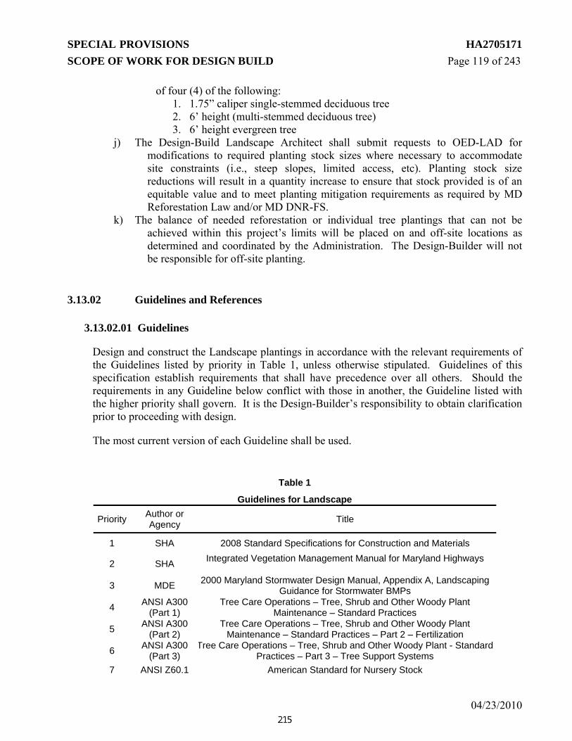
SPECIAL PROVISIONS HA2705171 SCOPE OF WORK FOR DESIGN BUILD Page 119 of 243
04/23/2010
of four (4) of the following: 1. 1.75” caliper single-stemmed deciduous tree 2. 6’ height (multi-stemmed deciduous tree) 3. 6’ height evergreen tree
j) The Design-Build Landscape Architect shall submit requests to OED-LAD for modifications to required planting stock sizes where necessary to accommodate site constraints (i.e., steep slopes, limited access, etc). Planting stock size reductions will result in a quantity increase to ensure that stock provided is of an equitable value and to meet planting mitigation requirements as required by MD Reforestation Law and/or MD DNR-FS.
k) The balance of needed reforestation or individual tree plantings that can not be achieved within this project’s limits will be placed on and off-site locations as determined and coordinated by the Administration. The Design-Builder will not be responsible for off-site planting.
3.13.02 Guidelines and References
3.13.02.01 Guidelines
Design and construct the Landscape plantings in accordance with the relevant requirements of the Guidelines listed by priority in Table 1, unless otherwise stipulated. Guidelines of this specification establish requirements that shall have precedence over all others. Should the requirements in any Guideline below conflict with those in another, the Guideline listed with the higher priority shall govern. It is the Design-Builder’s responsibility to obtain clarification prior to proceeding with design.
The most current version of each Guideline shall be used.
Table 1
Guidelines for Landscape
Priority Author or Agency Title
1 SHA 2008 Standard Specifications for Construction and Materials
2 SHA Integrated Vegetation Management Manual for Maryland Highways
3 MDE 2000 Maryland Stormwater Design Manual, Appendix A, Landscaping Guidance for Stormwater BMPs
4 ANSI A300 (Part 1)
Tree Care Operations – Tree, Shrub and Other Woody Plant Maintenance – Standard Practices
5 ANSI A300 (Part 2)
Tree Care Operations – Tree, Shrub and Other Woody Plant Maintenance – Standard Practices – Part 2 – Fertilization
6 ANSI A300 (Part 3)
Tree Care Operations – Tree, Shrub and Other Woody Plant - Standard Practices – Part 3 – Tree Support Systems
7 ANSI Z60.1 American Standard for Nursery Stock

SPECIAL PROVISIONS HA2705171 SCOPE OF WORK FOR DESIGN BUILD Page 120 of 243
04/23/2010
Table 1
Guidelines for Landscape
Priority Author or Agency Title
8 NRCS Pond Code 378, Visual Resource Design. Page 9
9 AASHTO Roadside Design Guide Chapters 4, 5, 6 and 10
10 AASHTO T88 and T194
11 SHA Highway Hydraulic Division Stormwater Management Facility Safety Policy for Design
12 COMAR Nutrient Management Law
13 SHA Storm Water Management Safety Policy
14 SHA Visual & Environmental Quality and Safety Criteria Review Guidelines
3.13.02.02 References
Use the references listed in Table 2 as supplementary materials for the design and construction of the Landscape plantings. These publications have no established order of precedence.
Table 2
References for Landscape Author or Agency Title
ANSI Z133.1 Safety Requirements for Pruning, Trimming, Repairing, Maintaining, and removing Trees, and for Cutting brush
Hortus Third A Concise Dictionary of Plants Cultivated in the United States and Canada (L. H. Bailey Hortorium 1976)
AASHTO A Guide for Transportation Landscape and Environmental Design
DNR Department of Natural Resources Article 5-103 – Maryland Reforestation Law; and Maryland Forest Conservation Act
DNR
The Maryland Roadside Tree Law Title 08
Department Of Natural Resources Subtitle 07 Forest And Parks
Chapter 02 Roadside Tree Care
3.13.03 General The Design-Builder shall provided a Landscape Architect who is a Maryland Licensed Landscape Architect with a minimum of ten (10) years of demonstrated landscape architectural design experience related to highway corridor design and construction. The Landscape Architecture must have a working knowledge of and experience with the implementation process of Context Sensitive Design/Solutions; native vegetation of the Mid-

SPECIAL PROVISIONS HA2705171 SCOPE OF WORK FOR DESIGN BUILD Page 121 of 243
04/23/2010
Atlantic Region; Maryland Reforestation Law (Natural Resources Article 5-103) and the Maryland Roadside Tree Law and stormwater management/bioretention facility design and landscaping. The administration reserves the right to request a resume to verify said qualifications. The Design-Builder shall design and construct Landscaping and Mitigation Plantings associated with the Project in accordance with these specifications. The Design-Builder Landscape Architect will be responsible for developing final Landscape Plans for review and approval by OED-LAD and OED-LOD, and these costs will be part of this contract.
The Design-Builder shall be responsible for determining whether existing subsoil and topsoil is available in sufficient quantities and that soil which is to be planted, seeded, or sodded is property prepared and/or amended in accordance with an approved Nutrient Management Plan (701.03.01 (b) SSCM) to provide successful plant establishment. The Design-Builder shall be responsible for furnishing additional subsoil and topsoil as necessary to provide successful plant establishment.
The Design-Builder shall prepare a Landscape Plan, to include mitigation plantings required under the Roadside Tree Law and/or MD Reforestation Law, proposed roadside groundcovers (including turfgrass and turfgrass sod establishment, meadow establishment, and shrub seeding), and other plantings. The Design-Builder shall be responsible for coordinating this Landscape plan work with other elements of work to be performed under the Project, including but not limited to final grading (including subsoil and topsoil placement), stormwater management facilities (including lined ponds and drainage swales), highway clear zones and sight distances, storm drain and culvert outfalls, utilities, signing, and lighting. If the Design-Builder or SHA identifies a conflict from one or more of these elements, the Design-Builder shall be responsible for modifying the plans.
Areas used for stormwater management shall not be used for Reforestation plantings or Landscape plantings, other than what is required as part of the stormwater management plans. The Design-Builder shall furnish seed and seed mixes according to SHA’s Standard Specifications for Construction and Materials – July 2008.
In addition to other requirements provided in the Contract Documents, the Design-Builder shall design and install landscape and mitigation plantings according to the following criteria:
3.13.03.01 Utility and Safety Setbacks
a) The Design-Builder shall avoid conflicts between trees and shrubs and existing and proposed/relocated utilities during design.
b) Trees and shrubs shall be planted a minimum of 5 ft. plus half the pipe/culvert diameter or other underground utility from the centerline of cross culverts, or pipes.
c) Trees which reach a height of 25 ft. or greater under typical highway conditions shall not be installed within 20’ of overhead electric lines. The Design-Build Team shall

SPECIAL PROVISIONS HA2705171 SCOPE OF WORK FOR DESIGN BUILD Page 122 of 243
04/23/2010
confirm appropriate setbacks for trees and/or shrubs from overhead and underground utilities and associated structures with the District 4 Utility Engineer in consultation with OED-LAD prior to commencing design of landscape plans.
d) Trees and shrubs shall be planted a minimum of 7 ft. from the centerline of swales and ditches. Larger setbacks may be required for lined and/or rip-rapped swales or swales with higher volume or velocity of flow.
e) Trees shall be offset from the edge of travel lanes in conformance to the AASHTO Roadside Design Guide and the SHA Integrated Vegetation Management Design Manual for Maryland Highways. Offsets shall be appropriate as per the roadway section, design speed, and vertical and horizontal alignment.
f) Additional setbacks may be required by the Administration for safety clear zones/recovery areas, to maintain sight distance, and/or for maintenance needs.
3.13.03.02 Low Maintenance Landscape Design
Roadside plantings, including but not limited to: landscaping and screening, reforestation, revegetation, and stormwater management facility/BMP landscaping shall be designed to balance aesthetic appeal, safety, and environmental stewardship with long-term maintenance requirements. The Design-builder shall minimize landscape maintenance needs as follows:
a) Arrange individual tree plantings, landscape beds, and plant masses to accommodate mowing and other maintenance operations in locations within or abutting areas of regularly mowed turfgrass.
b) Areas that will be regularly mowed to maintain clear sight distance or for other reasons, shall be seeded with turfgrass or sodded (SSCM 705 and 708).
c) In locations where regular mowing is not feasible or necessary for maintenance or safety considerations, (i.e. on slopes steeper than 4:1 or in reforestation, revegetation, or other naturalized areas) the Design-Builder shall specify meadow establishment, shrub seeding, or other native low-maintenance herbaceous plantings in lieu of turfgrass establishment or turfgrass sod establishment.
d) The use of shrub and perennial beds shall be minimized to high-visibility locations and plant spacing shall be tightened to outcompete weeds. Where space and sight distance allows, shrub and tree beds require less frequent maintenance than perennial beds. Masses of evergreen, flowering, and deciduous trees can provide substantial aesthetic benefit while requiring less annual maintenance than shrub or perennial beds.
3.13.03.03 Invasive Species Management
Successful landscape and mitigation plantings cannot be successfully established without management of invasive species and woody and herbaceous weeds.

SPECIAL PROVISIONS HA2705171 SCOPE OF WORK FOR DESIGN BUILD Page 123 of 243
04/23/2010
a) Invasive species and prohibited weeds, as listed in SSCM Section 920.06.02 Prohibited Weeds, shall be treated and removed within the project limits.
b) The Design-Builder shall develop a treatment plan and schedule detailing proposed methods for control and removal of invasive species/prohibited weeds for review and approval by the Office of Environmental Design-Landscape Operations Division.
c) Application of herbicides and pesticides shall be in accordance with all applicable SHA standard specifications, in accordance with Federal, State, and local laws, and per manufacturer’s specifications.
d) The Design-Builder shall conduct invasive species management operations as appropriate for proposed final landscape treatments.
3.13.04 Planting Zone Types
The Design-Builder shall design and install landscape and mitigation plantings that are appropriate to site conditions and constraints. While the General Landscape Design requirements apply to all plantings within the project limit, planting zones refer to areas with additional landscaping design criteria. The following Planting Zones are proposed within the limits of this Contract:
3.13.04.01 Turfgrass and Turfgrass Sod
The Design-Builder shall use Turfgrass Establishment (SSCM 705) or Turfgrass Sod Establishment (SSCM 708) in all locations requiring regular mowing maintenance as per the SHA Integrated Vegetation Management Manual for Maryland Highways, in areas were vegetation height must be controlled to maintain sight distance such as merge areas and roadside shoulder areas, in SWM management facilities, and elsewhere as specified in the Contract Documents.
3.13.04.02 Roadside Tree Mitigation Plantings
The Design-Builder shall provide mitigation plantings for Roadside Tree Impacts per 3.13.01.01. Trees provided as required mitigation for forest impacts under the MD Reforestation Law cannot be substituted for Roadside Tree Mitigation Plantings.
Roadside Tree Mitigation Plantings shall consist of a mixture of deciduous shade and ornamental and evergreen trees planted individually, in groups, and/or in naturalized massings where safety and site constraints permit. Trees shall be located to maximize ecological and aesthetic benefit, while weighing safety and maintenance constraints. For improved aesthetic benefit, trees in high-visibility locations shall be planted in groupings of a single species or in larger massings of single-species groupings where feasible. Roadside Tree Mitigation Plantings located in turfgrass areas shall be placed to accommodate mowing and maintenance operations. The Design-Builder shall select groundcovers other than turfgrass, (e. g: meadow

SPECIAL PROVISIONS HA2705171 SCOPE OF WORK FOR DESIGN BUILD Page 124 of 243
04/23/2010
establishment (SSCM Section 707), shrub seeding (SSCM Section 706), native herbaceous seeding, etc) in locations where regular mowing maintenance is not feasible or required. 3.13.04.03 Reforestation Plantings The Design-Builder shall provide Reforestation Plantings as mitigation for forest/woods impacts (impacts regulated under the MD Reforestation Law) per 3.13.01.02.
a) Plantings shall consist of random arrangements of native trees and shrubs, underplanted with native low-maintenance groundcover such as meadow or shrub seeding.
b) In highly visible portions of Reforestation and Revegetation Planting areas (such as roadside edges or areas on cut or fill slopes facing the highway, exit ramps, or secondary roads, the Design-Builder shall use single-species groupings of trees and shrubs or masses of single-species groupings rather than random plantings to increase aesthetic interest.
c) Reforestation areas shall be seeded with shrub seeding or other native seeding as approved by OED-LAD and OED-LOD.
d) Turfgrass Establishment or Turfgrass Sod Establishment shall not be used in Reforestation or Revegetation Planting areas without approval of OED-LAD.
3.13.04.04 Revegetation Plantings
The Design-Builder shall design and provide Revegetation Plantings according to the design criteria for Reforestation Plantings in 3.13.01 (f) 2, with the exception of the minimum area requirements.
a) The minimum width and area for Revegetation Plantings shall be 15 feet and 1,500 square feet, respectively.
b) The Design-Builder shall not substitute Revegetation Plantings for Reforestation Plantings required under the MD Reforestation Law as Revegetation Plantings do not qualify for credit under the law.
c) In highly visible portions of Revegetation Planting areas (such as roadside edges or areas on cut or fill slopes facing the highway, exit ramps, or secondary roads, the Design-Builder shall use groupings of single-species trees and shrubs or masses of single-species groupings rather than random plantings to increase aesthetic interest.
d) Revegetation areas shall be seeded with Shrub Seeding or other native seeding as approved by OED-LAD and OED-LOD.
e) Turfgrass Establishment of Turfgrass Sod Establishment shall not be used in Revegetation Planting areas without approval of OED-LAD.
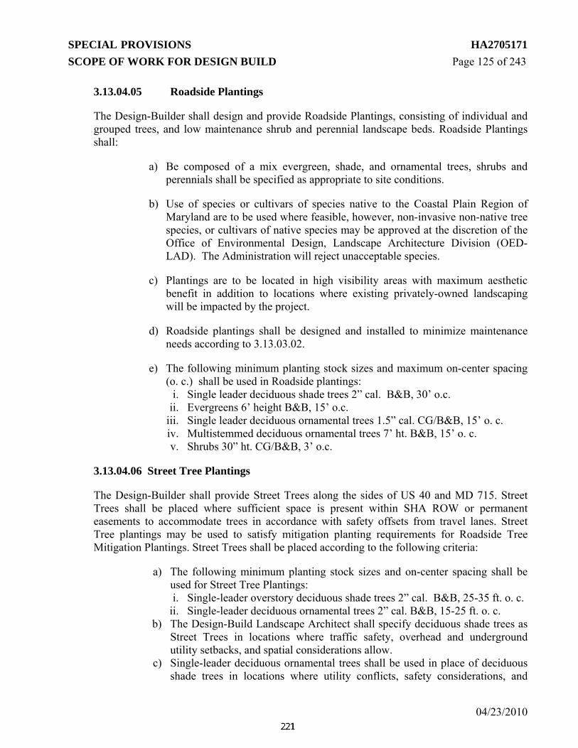
SPECIAL PROVISIONS HA2705171 SCOPE OF WORK FOR DESIGN BUILD Page 125 of 243
04/23/2010
3.13.04.05 Roadside Plantings
The Design-Builder shall design and provide Roadside Plantings, consisting of individual and grouped trees, and low maintenance shrub and perennial landscape beds. Roadside Plantings shall:
a) Be composed of a mix evergreen, shade, and ornamental trees, shrubs and perennials shall be specified as appropriate to site conditions.
b) Use of species or cultivars of species native to the Coastal Plain Region of Maryland are to be used where feasible, however, non-invasive non-native tree species, or cultivars of native species may be approved at the discretion of the Office of Environmental Design, Landscape Architecture Division (OED-LAD). The Administration will reject unacceptable species.
c) Plantings are to be located in high visibility areas with maximum aesthetic benefit in addition to locations where existing privately-owned landscaping will be impacted by the project.
d) Roadside plantings shall be designed and installed to minimize maintenance needs according to 3.13.03.02.
e) The following minimum planting stock sizes and maximum on-center spacing (o. c.) shall be used in Roadside plantings:
i. Single leader deciduous shade trees 2” cal. B&B, 30’ o.c. ii. Evergreens 6’ height B&B, 15’ o.c.
iii. Single leader deciduous ornamental trees 1.5” cal. CG/B&B, 15’ o. c. iv. Multistemmed deciduous ornamental trees 7’ ht. B&B, 15’ o. c. v. Shrubs 30” ht. CG/B&B, 3’ o.c.
3.13.04.06 Street Tree Plantings
The Design-Builder shall provide Street Trees along the sides of US 40 and MD 715. Street Trees shall be placed where sufficient space is present within SHA ROW or permanent easements to accommodate trees in accordance with safety offsets from travel lanes. Street Tree plantings may be used to satisfy mitigation planting requirements for Roadside Tree Mitigation Plantings. Street Trees shall be placed according to the following criteria:
a) The following minimum planting stock sizes and on-center spacing shall be used for Street Tree Plantings: i. Single-leader overstory deciduous shade trees 2” cal. B&B, 25-35 ft. o. c.
ii. Single-leader deciduous ornamental trees 2” cal. B&B, 15-25 ft. o. c. b) The Design-Build Landscape Architect shall specify deciduous shade trees as
Street Trees in locations where traffic safety, overhead and underground utility setbacks, and spatial considerations allow.
c) Single-leader deciduous ornamental trees shall be used in place of deciduous shade trees in locations where utility conflicts, safety considerations, and

SPECIAL PROVISIONS HA2705171 SCOPE OF WORK FOR DESIGN BUILD Page 126 of 243
04/23/2010
spatial constraints require. d) The Design-Build Landscape Architect shall specify Street Trees at a
sufficient caliper size to allow for them to be limbed up in locations where required to accommodate pedestrian or vehicular circulation.
3.13.04.07 Naturalized Roadside Areas and Steep Slope Plantings
In locations where regular mowing maintenance is not required per the SHA Integrated Vegetation Management Manual for Maryland Highways or feasible (such as on steep slopes) the Design-Builder shall specify and install vegetation for reduced mowing maintenance such as shrub seeding, meadow establishment, or other appropriate low-maintenance landscaping as approved by OED-LAD in consultation with OED-LOD. Meadow Establishment is appropriate in locations where mowing is necessary annually or every other year to control the growth of woody vegetation. Where mowing will not be required, shrub seeding (SSCM 706) and/or container grown woody plants shall be used unless otherwise approved by OED-LAD and OED_LOD. The Design Builder may include Reforestation, Revegetation, and/or Roadside Tree Mitigation Plantings within Slope Plantings and Naturalized Roadside Areas, provided the mitigation plantings meet the requirements for each planting type as noted in tc 3.13.
3.13.05 Stormwater Management Facility/BMP Landscape Plantings
For SWM facility/BMP plantings, the Design Build Team shall comply with SHA’s Visual & Environmental Quality and Safety Criteria Review Guidelines (VEQ Guidelines). No woody plants shall be installed within the liner limits of SWM facilities/BMP. Revisions to Section 9 of the VEQ Guidelines, included below, supersede the guidelines.
Section 9. Planting
Plantings can provide visual improvement to stormwater facilities, but offer other important benefits as well. Plants provide nutrient removal, shade, particulate pollutant removal, wildlife habitat, and natural heritage continuation. It is important utilize native vegetation when selecting plants for a selected site. This avoids the accidental introduction of invasive species, ensures greater likelihood of plant survival and adaptability, and allows the facility to merge into the adjacent landscape. Plantings should take on a natural appearance where possible. Groups of one plant species should be placed in loose drifts interspersed with individual plants of different species to improve visual quality. 9.1 Woody Plant Restrictions and Buffer Zones Planting of woody species, including live fascines, shall adhere to Pond Code 378 restrictions at SWM embankments and SWM outfall structures. The following shall also apply:
9.1.1. No woody material shall be planted on the SWM embankment (roadway and non-roadway),
within 15 feet of the toe of SWM embankment fill or within 25 feet of the SWM outfall structure
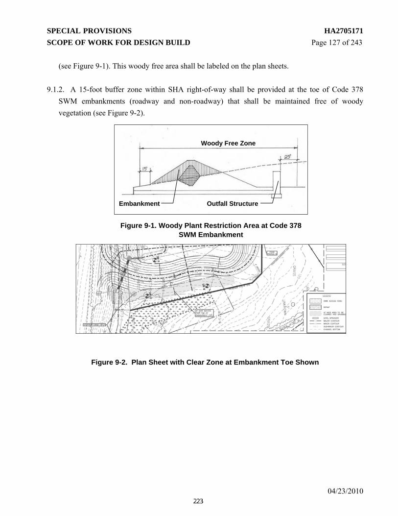
SPECIAL PROVISIONS HA2705171 SCOPE OF WORK FOR DESIGN BUILD Page 127 of 243
04/23/2010
(see Figure 9-1). This woody free area shall be labeled on the plan sheets.
9.1.2. A 15-foot buffer zone within SHA right-of-way shall be provided at the toe of Code 378 SWM embankments (roadway and non-roadway) that shall be maintained free of woody vegetation (see Figure 9-2).
Figure 9-2. Plan Sheet with Clear Zone at Embankment Toe Shown
Figure 9-1. Woody Plant Restriction Area at Code 378 SWM Embankment
Outfall Structure Embankment
Woody Free Zone

SPECIAL PROVISIONS HA2705171 SCOPE OF WORK FOR DESIGN BUILD Page 128 of 243
04/23/2010
9.2 Planting Height Restrictions at SWM Embankments SWM embankments and buffer zones shall be planted with turf grass that can be maintained to a height of 10 inches.
9.3 Plantings within Airport Zones Plantings within Airport Zoning Districtsshall be in compliance with the most recent Maryland Aviation Administration and/or Federal Aviation Administration requirements, as applicable.
9.4 Soil Amendments (Fertilizer, Lime, Compost, Mulch)
9.4.1. Soil tests shall be performed at the stormwater management facility site during design to determine the need to provide additional additives to the soil, determine if there are any toxic components to the existing soils and to determine where there is adequate topsoil to be salvaged and how much.
9.4.2. Soil amendments shall be applied as required according to soil testing to achieve healthy growth of plants and seed areas to ensure establishment. This includes turf establishment and plant pit amendments. Nutrient Management Plans shall be obtained from Landscape Operations Division (LOD) prior to application of soil amendments.
9.4.3. Areas targeted for warm season grass and native meadow establishment shall not be amended with fertilization and other amendments.
9.4.4. Mulch beds (shredded hardwood mulch) shall not be used in SWM facilities below the 10 year flood line, except for in Bioretention facilities. The mulch will float and clog orifices/openings.
9.5 Planting Requirements
The design shall provide planting according to the suggested planting for each zone that is required by the facility. Tables 9-1 and 9-2 on the following pages list the possible planting zones and requirements for planting at different facility types. Figure 9-3 graphically depicts the various planting zones.
9.5.1. Ponds shall have aquatic benches that are Emergent & Floating Aquatic Zones; water depths greater than 4 ft. that are submerged aquatic zones and storm elevations for up to the 10-year storm that are frequently fluctuating zones.
9.5.2. Wetlands shall have micro-pools or deep pools that are submerged aquatic zones, shallow wetland areas that are emergent & floating aquatic zones and water fluctuations up to the 10 year

SPECIAL PROVISIONS HA2705171 SCOPE OF WORK FOR DESIGN BUILD Page 129 of 243
04/23/2010
storm that are frequently fluctuating zones.
9.5.3. Both SWM ponds and wetlands shall have the perimeter shade planting, which covers the emergent zone through the frequently fluctuating zone.

Jan 2009 130
Figure 9-3. Stormwater Management Planting Zones

SPECIAL PROVISIONS CONTRACT NO. FR4275168 SCOPE OF WORK FOR DESIGN-BUILD 131 of 243
04/23/2010
Table 9-1. Recommended Minimum Planting Requirements at SWM Ponds and Wetland Hydrologic Zones
Quantity/ Placement Considerations Min. Size/Rate Root Condition
Submerged Aquatic Zone (4 ft. or greater depth permanent water)
• 1 plant per 9 cu. ft. of water volume for water depths 4 ft. or deeper.
• Min. 2 species with no one species being greater than 60% of the total plants
8 in. ht./length Bare root
Emergent & Floating Aquatic Zone (up to 18 in. depth permanent water)
• 24 in. centers max. spacing (2.9 plants per 10 sq. ft.)
• Min. 3 species shall be provided with no one species being greater than 50% of the total plants in this zone
• Min. 30% of the species shall be broadleaved or floating leaved
#1 Container grown
Frequently Fluctuating Zone (permanent water surface to 10 yr. water storm elev.)
Live Fascines or Wattles (optional)
• 3 species in each fascine bundle
• Place parallel to contours
• Min. one layer of fascines at water’s edge
• Do not use when facility is lined
4 in. diameter by 6 ft. length
Bound bundles
Plug Planting
• Min. 3 species of plugs shall be provided with no one species being greater than 50% of the total plants in this zone
• Plugs shall be spaced at max. 24 in. centers (2.9 plants per 10 sq. ft.)
2.25 x 5” deep Plug

SPECIAL PROVISIONS CONTRACT NO. FR4275168 SCOPE OF WORK FOR DESIGN-BUILD 132 of 243
04/23/2010
Table 9-1. Recommended Minimum Planting Requirements at SWM Ponds and Wetland Hydrologic Zones
Quantity/ Placement Considerations Min. Size/Rate Root Condition
Seed and Mulch
• Shall be included to provide permanent stabilization
• SWM Seed Mix
• SHA Special Purpose Mix
• Mulch shall be according to SSCM 2008, Section 705.03.09.
• No straw mulch shall be used at SWM facilities. Wood cellulose fiber mulch is to be used.
• Overseeding of existing vegetation is to provided if sufficient groundcover of desirable species is not present after the Plant Establishment Phase (1 year)
16 lbs./ac. 10 lbs/ac.
Seed
Perimeter Shade Planting (emergent & floating aquatic zone to 10 yr. water storm elev.)
Deciduous Canopy Trees
• 1 tree if areas is ≤ 4,000 SF (measured at 10 YR water surface contour line)
• 3 trees if (4,000 SF < area ≤ 8,000 SF)
• 5 trees if (8,000 SF < area ≤12,000 SF)
• If area > 12,000 SF, add 1 additional tree for each additional 4,000 SF
• If facility is lined, no trees or woody shrubs allowed within limits of liner
2 in. cal. (smaller stock may be utilized on steep slopes)
B & B (Container grown stock is acceptable for trees up to 1.5 in. cal.)
Evergreen Trees/Needle-Leaved Conifers 6 ft. height B & B
Understory or Ornamental Trees
• 2 if area is ≤ 4,000 SF, add 1 additional tree for each additional 1,000 SF
• Multiple stemmed trees shall have a min. of 3 trunks.
1 ¾ in. cal. If single stemmed 5 ft. ht. if multi-stemmed
B & B
Woody Shrubs
5 for every understory or flowering tree required
24 in. ht. or spread
Container Grown
(#3 Min)

SPECIAL PROVISIONS CONTRACT NO. FR4275168 SCOPE OF WORK FOR DESIGN-BUILD 133 of 243
04/23/2010
Table 9-1. Recommended Minimum Planting Requirements at SWM Ponds and Wetland Hydrologic Zones
Quantity/ Placement Considerations Min. Size/Rate Root Condition
Planting Bed Preparation
• Planting beds mulched with shredded hardwood bark shall not be used at SWM facilities below the 10 YR water surface elevation. Instead, individual plants shall be installed in plant pits that are not mulched.
• Areas between planting pits shall be stabilized with seed and mulch
Seed and Mulch
See Frequently Fluctuating Zone seed and mulch requirements.
Table 9-2. Recommended Minimum Planting Requirements
for SWM Filtering Practices (organic filter, dry swales)
Quantity/ Placement Considerations Min. Size/Rate Root Condition
Organic Filter
Sod
• Flow shall be diverted from filter practices until 2 in. ht. of permanent turf stabilization has been established
• In cases where flow cannot be diverted, sod shall be applied to the filter surface
Section 708 Section 920 (SSCM 2008)
Seed and Mulch
• SWM Seed Mix
• Special Purpose Mix
• No straw mulch shall be used at SWM facilities.
8 lbs / ac.
10 lbs / ac.
Bioretention
Trees
• Min. 0.76 Deciduous canopy trees per 100 SF (filter surface area measurement)
2 inch cal. B&B

SPECIAL PROVISIONS CONTRACT NO. FR4275168 SCOPE OF WORK FOR DESIGN-BUILD 134 of 243
04/23/2010
Table 9-2. Recommended Minimum Planting Requirements
for SWM Filtering Practices (organic filter, dry swales)
Quantity/ Placement Considerations Min. Size/Rate Root Condition
Organic Filter
• Substitution of (2) Understory/ornamental trees (1.5” cal. single stem or 5’ height multistem) per each (1) deciduous canopy tree is permitted where site constraints preclude use of canopy trees.
• Filter medium depth ≥ 5 ft.
• If the facility has underdrains or is lined, large canopy trees should not be placed directly in the bioretention facility. Instead, they should be placed adjacent to the facility to provide shade to understory plants. In this case, plant large trees 5 feet away from the perimeter of the filter medium/underdrains or liner.
• No straw mulch shall be used at SWM facilities.
Shrubs
• Min. 2.8 shrubs per 100 SF (filter surface area measurement)
• Filter medium ≥ 2.5 ft.
24 in. ht. or spread
Container Grown (#3 Min)
Herbaceous layer
• 3 perennials or grasses can be substituted for 1 required shrub
• No more than 50% of plants shall be perennial or grasses
#1 container
Container Grown
Mulch
• 3 in. depth shredded hardwood mulch, evenly distributed and raked smooth
Section 920
(SSCM 2008)
9.6 General Planting Guidelines
9.6.1. Low Maintenance Planting – Avoid the use of mulched planting beds unless appropriate and there is a commitment for maintenance from LOD.
9.6.2. Woody trees and shrubs shall not be planted where a pond liner is used. Herbaceous species may be allowed depending upon the depth of cover at the liner, but installation procedures shall involve hand digging rather than augers.

SPECIAL PROVISIONS CONTRACT NO. FR4275168 SCOPE OF WORK FOR DESIGN-BUILD 135 of 243
04/23/2010
9.6.3. Organic filters and bioretention facilities have underdrains. Plants shall be selected so that their roots do not grow deep enough to clog underdrains. If BSM is ≤ 4 ft. deep, the largest woody species shall be understory trees. Canopy trees shall not be used in bioretention facilities
9.6.4. Mowability shall be addressed in the planting zones so that planting does not inhibit equipment accessing critical areas to be maintained.
9.6.5. The stopping sight distance at ramps and sight distance at intersections shall be checked (AASHTO Roadside Design Guidelines, Chapter 3).
9.6.6. Use of species of the Fraxinus genus is not permitted on SHA projects.
9.6.7. Temporary seeding and mulching should be provided where appropriate.
9.6.8. Benches are an excellent opportunity for landscape plantings.
9.6.9. Consider use of the Visual Quality Monitor specification on the project, and discuss this with the HHD task leader. Note that a task will need to be set up for the person to fill this role and this person should attend the pre-construction meeting to introduce themselves to the contractor and construction engineer.
9.6.10. Additional watering is incidental to plant cost per the 2008 SHA Standard Specifications for Construction and Materials.
9.6.11. Seed mixes should consist of appropriate species. The application rate should be sufficient to establish a good cover. Species and application rates for project-specific mixes shall be approved by the Landscape Operations Division.
9.6.12. The delineation of the area of the core trench of a SWM pond shall be shown on the planting plan to ensure that no woody vegetation is planted on the pond embankment.
9.6.13. Edge of liners shall be shown on the planting plan so the contractor will be cognizant and take care not to puncture them when installing plant material.
9.6.14. For plantings located a significant distance from motorized equipment access, or where trees are to be installed on slopes steeper than 4:1, a reduction in the minimum size may be appropriate. Where reduction in the size of individual planting stock is necessary,

SPECIAL PROVISIONS CONTRACT NO. FR4275168 SCOPE OF WORK FOR DESIGN-BUILD 136 of 243
04/23/2010
SHA may require an increase in the quantity of trees to provide an equivalent total caliper measurement for the project. For example, on a 3:1 slope, four 1.5 inch caliper trees may be substituted in place of three 2 inch caliper trees. On slopes greater than 3:1, use of material over 1 ¾ caliper is not recommended.
9.6.15. Turf grass should be established at the access road if topsoil is applied.
9.7 Vegetation Management
9.7.1. If an existing facility or site is overgrown and has invasive species, an appropriate vegetation management specification should be included, subject to review and approval by SHA-Landscape Operations Division.
9.7.2. Crew days or a lump sum amount to accompany vegetation management performance specifications should be included in the bid items to cover the vegetation management.

SPECIAL PROVISIONS CONTRACT NO. HA2705170 SCOPE OF WORK FOR DESIGN-BUILD 137 of 243
4/23/2010
TC SECTION 3.14 GEOTECHNICAL PERFORMANCE SPECIFICATION
3.14.01 GENERAL
This Geotechnical Performance Specification shall only apply to all geotechnical components in phase 2 of the project as described in TC 2.07.02. The geotechnical components in Phase 1 of this project shall be constructed according to the plans and specifications provided. Therefore, the phrase “All geotechnical components” contained in the sections below shall only refer to the geotechnical aspects of the project in phase 2. The Design-Builder shall conduct supplemental subsurface explorations, analyses, design and construction for all geotechnical components of the Project in accordance with all applicable criteria and standards cited herein and in accordance with this Geotechnical Performance Specification.
3.14.02 Guidelines and References
3.14.02.01 Guidelines
Design and construction of all geotechnical elements shall be in accordance with this Geotechnical Performance Specification and the relevant requirements of the following Guidelines and references unless otherwise stipulated in this specification. Guidelines and references specifically cited in the body of this Geotechnical Performance Specification establish requirements that shall have precedence over all others. Should the requirements in any Guideline conflict with those in another, the Guideline listed with highest priority in Table 1 shall govern unless otherwise stipulated in this specification. Listed under references are reports and resources that the Design-Builder may use to address the geotechnical requirements as the Design-Builder sees fit. It is the Design-Builder’s responsibility to obtain clarification for any unresolved ambiguity prior to proceeding with any design and construction. All Geotechnical Reports and Submissions will be reviewed based upon FHWA Geotechnical Checklist and Guidelines (FHWA-ED-88-053).
Use the most current version of each listed guideline as of the initial publication date of this RFP unless revised by addendum or contract modification.

SPECIAL PROVISIONS CONTRACT NO. HA2705170 SCOPE OF WORK FOR DESIGN-BUILD 138 of 243
4/23/2010
TABLE 1 GUIDELINES FOR GEOTECHNICAL
Priority Author or Agency
Title
1 SHA Office of Bridge Development, Policy and Procedure Manual 2 AASHTO Standard Specification for Highway Bridges, 17th Edition 3 SHA Standard Specifications for Construction and Materials 4 AASHTO Manual on Subsurface Investigations 5 AASHTO Standard Specifications for Structural Supports for Highway
Signs, Luminaries and Traffic Signals, 4th Edition
6 AASHTO Standard Specifications for Transportation Materials and Methods of Sampling and Testing – Parts I and II
7 ASTM Annual Books of Standards 8 MDE 2000 Maryland Storm Water Design Manual Volumes I and II
( including 2009 revisions) 9 FHWA Mechanically Stabilized Earth Walls and Reinforced Soil slopes,
Design and Construction Guidelines 10 SHA Book of Standards for Highway and Incidental Structures 11 SHA Manual For The Inspection of Highway Right of Way In Karst
Areas
3.14.02.02 References
Use the references listed in Table 2 as supplementary materials for the design and exploration of the geotechnical subsurface. These publications have no established order of precedence.
TABLE 2
REFERENCES FOR GEOTECHNICAL
Author or Agency
Title
FHWA Corrosion/Degradation of Soil Reinforcements for Mechanically Stabilized Earth Walls and Reinforced Slopes
FHWA Design and Construction of Driven Pile Foundations, Volumes 1 and 2

SPECIAL PROVISIONS CONTRACT NO. HA2705170 SCOPE OF WORK FOR DESIGN-BUILD 139 of 243
4/23/2010
FHWA Drilled Shafts: Construction Procedures and Design Methods, Volumes 1 and 2
FHWA Geosynthetic Design and Construction Guidelines FHWA Geotechnical Engineering Circular No. 1: Dynamic Compaction FHWA Geotechnical Engineering Circular No. 2: Earth Retaining Systems FHWA Geotechnical Engineering Circular No. 4: Ground Anchors and
Anchored Systems FHWA Geotechnical Engineering Circular No. 5: Evaluation of Soil and
Rock Properties FHWA Geotechnical Engineering Circular No. 6: Shallow Foundations FHWA Geotechnical Engineering Circular No. 7: Soil Nail Walls FHWA Durability of Geosynthetics for Highway Applications FHWA FHWA FHWA
Ground Improvement Technical Summaries Volume I and II Geotechnical Aspects of Pavement Continuous Flight Augur Pile Foundations
FHWA Micropile Design and Construction Guidelines FHWA The Osterberg Load Cell for Load Testing Drilled Shafts and
Driven Piles Dunnicliff Geotechnical Instrumentation for Monitoring Field Performance,
Dunnicliff 1986 SHA Standard Specifications for Subsurface Investigations FHWA Subsurface Investigations (Geotechnical Site Characterization) Subsurface Investigations - Geotechnical Site Characterization
Reference Manual for NHI 132031 FHWA Geotechnical Instrumentation
3.14.03 REQUIREMENTS
3.14.03.01 Geotechnical Subsurface Exploration
3.14.03.01.01 Preliminary Subsurface Data
The Administration has completed a subsurface investigation to provide preliminary geotechnical subsurface investigation. The results of the preliminary geotechnical subsurface investigation consist of Standard Penetration Test (SPT) borings, auger borings, and/or laboratory testing. These borings were obtained with reasonable care and recorded in good faith. This information was prepared and is intended for the

SPECIAL PROVISIONS CONTRACT NO. HA2705170 SCOPE OF WORK FOR DESIGN-BUILD 140 of 243
4/23/2010
Administration’s estimate purposes. Its presentation on the plans or elsewhere is for the purpose of providing intended users with access to the same information available to the Administration. The Administration neither assumes nor implies any warranty regarding the data provided, other than that the information was obtained at locations and depths indicated and to the accuracy of the data at the time of testing. The subsurface information presented is not intended as a substitute for a subsurface investigation by the Design-Builder. The Design-Builder shall conduct additional studies in accordance with the minimum scope specified herein. The Design-Builder shall note that the Geotechnical Data Reports, which contain the geotechnical data obtained by the Administration for this Work, is included in Project Wise. Data reports generated from the preliminary studies conducted for the Administration are provided to the Design-Builder for evaluation of the subsurface conditions along the alignment and for the various design elements. The Design-Builder shall conduct additional subsurface investigation using various exploration techniques such as test borings, test pits, and geophysical surveys for the design and construction of the project.
3.14.03.01.02 Design-Builder’s Subsurface Exploration
The Design-Builder shall form its own interpretation of the existing data and satisfy itself as to the nature of the subsurface conditions, the form and nature of the site and nature of the Work that may affect its detailed design, construction methods, and tools. The Design-Builder shall undertake its own assessment of the suitability of the preliminary geotechnical data.
The data from the preliminary geotechnical subsurface investigation shall not serve as the sole basis for the Design-Builder’s final design. The studies were performed by the Administration at a limited number of locations along the site and additional information is required for detailed design and construction. Except for the Administration designed structures, the Design-Builder shall prepare and implement a subsurface exploration and testing program with all field, laboratory testing (Table 3 & 4) and geophysical study necessary to establish the subsurface conditions and to perform all geotechnical and foundation design and analyses. The program, herein designated as the Design-Builder’s subsurface exploration program, shall be developed and implemented to supplement the data provided by the Administration and to obtain the data as required to meet the requirements of AASHTO and the Design-Builder’s design approach and construction methods. The locations, number, depths and types of boreholes, laboratory and field-testing and sampling shall conform to the standards of practice of the Administration, AASHTO and the FHWA. The details of the Design-Builder’s field, laboratory and geophysical testing programs for design shall be submitted to the Administration as part of the Geotechnical Planning Reports for review and comment (See Section 3.14.05
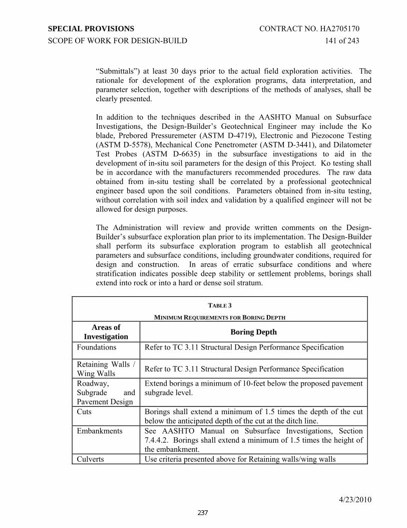
SPECIAL PROVISIONS CONTRACT NO. HA2705170 SCOPE OF WORK FOR DESIGN-BUILD 141 of 243
4/23/2010
“Submittals”) at least 30 days prior to the actual field exploration activities. The rationale for development of the exploration programs, data interpretation, and parameter selection, together with descriptions of the methods of analyses, shall be clearly presented.
In addition to the techniques described in the AASHTO Manual on Subsurface Investigations, the Design-Builder’s Geotechnical Engineer may include the Ko blade, Prebored Pressuremeter (ASTM D-4719), Electronic and Piezocone Testing (ASTM D-5578), Mechanical Cone Penetrometer (ASTM D-3441), and Dilatometer Test Probes (ASTM D-6635) in the subsurface investigations to aid in the development of in-situ soil parameters for the design of this Project. Ko testing shall be in accordance with the manufacturers recommended procedures. The raw data obtained from in-situ testing shall be correlated by a professional geotechnical engineer based upon the soil conditions. Parameters obtained from in-situ testing, without correlation with soil index and validation by a qualified engineer will not be allowed for design purposes.
The Administration will review and provide written comments on the Design-Builder’s subsurface exploration plan prior to its implementation. The Design-Builder shall perform its subsurface exploration program to establish all geotechnical parameters and subsurface conditions, including groundwater conditions, required for design and construction. In areas of erratic subsurface conditions and where stratification indicates possible deep stability or settlement problems, borings shall extend into rock or into a hard or dense soil stratum.
TABLE 3
MINIMUM REQUIREMENTS FOR BORING DEPTH Areas of
Investigation Boring Depth
Foundations Refer to TC 3.11 Structural Design Performance Specification
Retaining Walls / Wing Walls Refer to TC 3.11 Structural Design Performance Specification
Roadway, Subgrade and Pavement Design
Extend borings a minimum of 10-feet below the proposed pavement subgrade level.
Cuts Borings shall extend a minimum of 1.5 times the depth of the cut below the anticipated depth of the cut at the ditch line.
Embankments See AASHTO Manual on Subsurface Investigations, Section 7.4.4.2. Borings shall extend a minimum of 1.5 times the height of the embankment.
Culverts Use criteria presented above for Retaining walls/wing walls

SPECIAL PROVISIONS CONTRACT NO. HA2705170 SCOPE OF WORK FOR DESIGN-BUILD 142 of 243
4/23/2010
TABLE 3 MINIMUM REQUIREMENTS FOR BORING DEPTH
Areas of Investigation Boring Depth
Stormwater Management
See the 2000 Maryland Storm Water Design Manual Volumes I and II (including 2009 revisions)
Noise Walls and High Mast Lighting
See foundation requirements above.
TABLE 4
MINIMUM REQUIREMENTS FOR SPT BORING LAYOUT* Geotechnical
Features Boring Layout
Foundations Refer to TC 3.11 Structural Design Performance Specification Retaining Walls Refer to TC 3.11 Structural Design Performance Specification Roadways,Subgrade and Pavement Design
The spacing between borings along the roadway alignment shall not exceed 500-feet.
Roadway Embankments and Cuts
See AASHTO Manual on Subsurface Investigations, Section 7.4.3.2. For the most critical section, at least three borings (at toe of the slope, crest of the slope and top of the slope) shall be conducted to establish the soil profile for slope stability analysis.
Culverts AASHTO Manual of Subsurface Investigations, Section 7.4.3.3. Stormwater Management (SWM)
See the 2000 Maryland Storm Water Design Manual Volumes I and II(Including 2009 revisions)
Highmast Poles See Guideline #5 above.
Among the requirements for the subsurface investigation and laboratory testing to be performed for the Project are the following:
A) Supervision and Inspection – All geophysical investigations shall be planned and performed under the direct supervision of a geophysicist with a minimum of 10 years experience. All boring and in-situ testing inspection shall be performed by field inspectors that have passed the NHI Subsurface Investigation Qualification Course (#132079), and; (a) be a degreed engineer or geologist; or, (b) have a minimum of two (2) years of field experience in the inspection and reporting of field sampling and testing of similar size and content. All field investigations and laboratory testing shall be performed under the direct supervision of a Maryland-registered professional engineer with a minimum of five (5) years experience in the performance and supervision of geotechnical engineering Projects. The Administration reserves the right to request a resume to verify said qualifications.

SPECIAL PROVISIONS CONTRACT NO. HA2705170 SCOPE OF WORK FOR DESIGN-BUILD 143 of 243
4/23/2010
B) Location and Ground Surface Elevation - The Design-Builder shall determine the coordinate location, Station and Offset and ground surface elevation, for each boring and other test probes and show the information on the individual boring logs.
C) Visual soil identification as reported on the boring logs shall be in accordance with ASTM D-2488. For description for soil samples with laboratory test results, the description shall include the AASHTO and USCS soil classification. For description for soil samples of SWM with laboratory test results, the description shall also include USDA soil classification.
D) Final boring and rock core logs shall be prepared and presented using gINT software as supplied by gINT Software, Inc. The Administration will provide the gINT electronic template.
E) The soils and rock samples obtained by the Design-Builder for the supplemental subsurface investigation are the property of the Administration. The Design-Builder shall deliver all samples to the designated location upon completion.
F) The Design-Builder shall determine groundwater table depth/elevation and seepage conditions at the project site.
G) All drilling equipment shall be calibrated and the Design-Builder shall provide the efficiency of all hammers to be used for this project.
H) The Design-Builder shall use all information obtained from the testing program to prepare a subsurface profile in order to determine the adequacy of the site investigation program.
I) Boreholes shall be covered with bags of sand or metal plates and topped with orange cones for 24 hours and until obtaining the 24 hour water reading. After reading is taken, abandoned borehole shall be sealed in accordance with MDSHA Standard Specifications for Subsurface Explorations. Spoils shall be evenly distributed to surrounding areas.
(J) The Contractor shall calibrate all drilling equipment based on SPT analyzer testing data and provide the efficiency of the SPT hammers and sampling assembly used for this project on the boring logs. The Administration reserves the right to verify the efficiency of the Contractor’s hammer and sampling assembly provided on the boring logs.
See the Environmental Performance Specification for specifics regarding stream crossing, wetland, and buffer zones. See the Maintenance of Traffic Performance Specification for the specifics regarding maintenance of traffic requirements that will be required during any subsurface exploration activities.

SPECIAL PROVISIONS CONTRACT NO. HA2705170 SCOPE OF WORK FOR DESIGN-BUILD 144 of 243
4/23/2010
3.14.03.01.03 Laboratory Testing
After collecting soil and rock samples, laboratory tests will be performed to quantify material properties and verify design assumptions. The type and number of tests required are primarily a function of the variability of the site, the purpose of the study, and the amount of risk and potential consequences of failure. Sufficient laboratory testing shall be performed so that the Design-Builder’s Geotechnical Engineer and the Administration’s Geotechnical Engineer are satisfied that the test results are representative of in-situ conditions. All standard soil and rock sample laboratory testing shall be performed in accordance with the appropriate AASHTO test designation. All laboratory testing shall be performed by laboratories with AASHTO Materials Reference Laboratory (AMRL) certification for each specific test performed. Laboratory testing conducted on undisturbed samples shall be performed no more than 7 calendar days after sample retrieval. Laboratory consolidated undrained (CU) and unconsolidated undrained (UU) testing shall be used to determine the undrained shear strength, Su. As indicated in Section 3.14.03.01.02, the Design-Builder can supplement the subsurface investigation with in-situ testing. For Determination of the undrained shear strength using in situ testing such as CPT, DMT, and PMT shall be calibrated with the appropriate level of triaxial testing. For relatively thick deposits of cohesive soil layers, profiles of the undrained shear strength Su as function of depth shall be obtained so that the stress history and properties can be ascertained. Strength measurements from hand torvanes, pocket penetrometers, or unconfined compression tests shall not be used to determine undrained shear strength. Long-term effective stress strength parameters, c’ and Φ’, of cohesive soils shall be evaluated by consolidated drained (CD) triaxial tests, or consolidated undrained (CU) triaxial tests with pore pressure measurements. Long-term effective stress strength parameters, c’ and Φ’, of cohesive soils shall not be evaluated by Direct Shear tests. In laboratory tests, the rate of shearing load application shall be sufficiently slow to ensure substantially complete dissipation of excess pore pressure in the drained tests, or, in undrained tests, complete equalization of pore pressure throughout the specimen. Any cost associated with the laboratory testing and the approval of the material sources will be at the Design-Builder's cost. All material tested shall be kept until the Administration's approval is granted for that design element.
3.14.03.02 Geotechnical Design
3.14.03.02.01 Selection of Design Properties
The following process shall be followed in selecting material Engineering properties

SPECIAL PROVISIONS CONTRACT NO. HA2705170 SCOPE OF WORK FOR DESIGN-BUILD 145 of 243
4/23/2010
for design:
• Select samples for performance testing, • Conduct laboratory testing program, • Review the quality of the laboratory data, • Select material properties for design.
Subsurface soil or rock properties shall be determined using one or more of the following methods:
• in-situ testing during the field exploration program, including consideration of any geophysical testing conducted,
• laboratory testing, • and back analysis of design parameters based on site performance data.
The selection of soil shear strength for design shall consider, at a minimum, the following:
• the rate of construction loading relative to the hydraulic conductivity of the soil, i.e., drained or undrained strengths;
• the effect of applied load direction on the measured shear strengths during testing;
• the effect of expected levels of deformation for the geotechnical structure; and • the effect of the construction sequence.
Laboratory testing shall be performed to estimate the soil strength and verify values determined from in-situ testing. Where collection of undisturbed samples for laboratory testing is difficult, values obtained from in-situ testing methods may be used after proper and acceptable correlation practices approved by the Administration. Strength measurements from hand torvanes, pocket penetrometers, or unconfined compression tests shall not be used to evaluate undrained shear strength for design analyses. Correlations for Su based on in-situ test measurements shall not be used for final design unless they have been calibrated to the specific soil profile under consideration. Correlations for Su based on SPT tests will not be allowed. The selection of peak, fully softened, or residual strength for design analyses shall be based on a review of the expected or tolerable displacements of the soil mass. The use of a nonzero cohesion intercept (c’) for long-term analyses in natural materials will not be allowed. The drained friction angle of granular deposits may be evaluated by correlation to the results of SPT testing, CPT testing, or other relevant in-situ tests. Parameters obtained from in-situ testing, without correlation with soil index and validation by a qualified engineer will not be allowed for design purposes. Laboratory shear strength tests on undisturbed samples, if feasible to obtain, or reconstituted disturbed samples, may

SPECIAL PROVISIONS CONTRACT NO. HA2705170 SCOPE OF WORK FOR DESIGN-BUILD 146 of 243
4/23/2010
also be used to determine the shear strength of granular soils. If SPT N values are used, unless otherwise specified for the design method or correlation being used, they shall be corrected for the effects of overburden pressure and for hammer efficiency. Care shall also be exercised when using SPT blow counts to estimate soil shear strength if in soils with coarse gravel, cobbles, or boulders. Large gravels, cobbles, or boulders could cause the SPT blow counts to be unrealistically high. Consolidation parameters Cc, Cr, Cα shall be determined from the results of one-dimensional consolidation tests. To assess the potential variability in the settlement estimate, the average, upper and lower bound values obtained from testing shall be considered. Where evaluation of elastic settlement is critical to the design of the foundation or selection of the foundation type, in-situ methods such as PMT or DMT for evaluating the modulus of the stratum shall be used. The coefficient of consolidation, Cv, shall be determined from the results of one-dimensional consolidation tests. The variability in laboratory determination of Cv results shall be considered in the final selection of the value of Cv to be used for design. CPTu tests in which the pore pressure dissipation rate is measured may be used to validate the laboratory testing for the value of Cv. Results from unconfined compression test and direct shear test on cohesive soils will not be allowed. The strength of intact rock material shall be determined using the Standard Test Method for Unconfined Compressive Strength of Intact Rock Core Specimens (ASTM D2938) or the Standard Test Method for Determination of the Point Load Strength Index of Rock (ASTM D5731). If Point Load Strength tests are used, but the results shall be verified and calibrated using unconfined compression tests. The rock shall be classified using the rock mass rating system (RMR). The soil and rock properties are vital in the analysis of the stability of structures. The Design-Builder shall validate the properties of each soil or rock stratum with the testing program. In case of dispute over validity of design parameters or testing data, the Administration may require the Design-Builder to supply test data from an Administration approved laboratory at the Design-Builder's cost to support the design parameters or testing data used in the design.
3.14.03.03 Design of Foundations
Refer to TC 3.11 Structural Design Performance Specification and the requirements below for design of foundations. The criteria set forth herein shall pertain to the geotechnical and foundation design

SPECIAL PROVISIONS CONTRACT NO. HA2705170 SCOPE OF WORK FOR DESIGN-BUILD 147 of 243
4/23/2010
and shall conform to AASHTO Standard Specifications for Highway Bridges 17th Edition, using the service load (allowable stress) design method, or as otherwise specified herein. A deep foundation shall be used where a shallow foundation cannot be designed to carry the applied loads or displacements safely. Deep foundations shall also be used where scour, erosion, or unacceptable settlement might occur. No scour analysis is necessary as there are no water crossings in the project.
3.14.03.03.01 Shallow Foundations
Shallow foundations shall include spread footings for strip footings, and mats or raft foundations beneath an entire structure area. Shallow foundations may be used where there is a suitable bearing stratum near the surface and where there are no compressible layers or soils susceptible to collapse or expansion below. Shallow foundations shall not be placed in existing or proposed fills or embankments. Shallow Foundation shall not be placed in the reinforced portion of MSE abutments or in the fill behind the MSE abutment. Foundation design shall accommodate potentially detrimental substances in soil or groundwater, such as chlorides and sulfates. Shallow foundations shall be designed to meet the bearing capacity, settlement and external stability requirements of this specification and AASHTO specification. Effects of adjacent foundations, variable groundwater conditions and surcharge loads shall be accommodated when evaluating foundation settlements and bearing capacity. Uplift of spread footings will not be permitted.
3.14.03.03.01.1 Bearing Capacity
Shallow foundations shall be analyzed for bearing capacity to confirm that the underlying soil can resist the footing loads without bearing capacity failure. A factor of safety of at least 3.0 shall be provided against bearing capacity failure for AASHTO Group I loading. The desired bearing value shall be validated by the required site investigation and laboratory testing program. The Design-Builder will be required to confirm the bearing value using an in-situ testing program. Groundwater and its variation shall be documented in the calculation of the bearing value. An approved ground improvement technique may be accepted to improve the bearing value.

SPECIAL PROVISIONS CONTRACT NO. HA2705170 SCOPE OF WORK FOR DESIGN-BUILD 148 of 243
4/23/2010
3.14.03.03.01.2 Settlement
Analyses shall be conducted to estimate the total and differential soil settlement induced by the foundation loads. Immediate settlements for granular soils and immediate, primary and secondary consolidation settlements for cohesive soils shall be accommodated. Shallow foundations shall be designed to keep estimated settlements within the allowable values as specified in AASHTO 4.4.7.2.5.
3.14.03.03.01.3 External Stability
Shallow foundations shall be analyzed and constructed for external stability, including sliding, overturning and global slope stability. A minimum factor of safety of 1.5 shall be provided against sliding and global slope stability. A minimum factor of safety of 2.0 shall be provided against overturning failure. Passive earth pressure in front of the foundation shall not be used in the evaluation of sliding and overturning modes. Shallow foundations shall be designed such that the resultant load falls within the middle third of the foundation.
3.14.03.03.02 Deep Foundations
Deep foundations may include timber driven piles, steel driven piles or drilled shafts. Pre-cast pre-stressed concrete piles, auger cast in place, rammed aggregate piers, screw piles, or existing foundations will not be considered for use on this Project. When designing deep foundations, design and construction shall include accommodations to minimize the level of construction noise and the radius of influence from construction vibrations. Piles and drilled shafts shall be designed in accordance with the requirements of AASHTO 17th Edition Standards, TC 3.11 Structural Design Performance Specification, and as required below for material requirements and structural design of foundation elements. The minimum length for steel driven piles shall be 12-feet. The center-to-center spacing of drilled shafts and round piles shall not be less than three times the drilled shaft or pile diameter. Piles shall be designed and constructed such that neither tension loads nor load reversals occur under any loading conditions.
3.14.03.03.02.1 Axial Capacity
Deep foundations shall be analyzed for axial compression, using static analysis methods in accordance with AASHTO specifications and manuals. A factor of safety consistent with the level of construction control shall be applied to the ultimate capacity of driven piles in accordance with AASHTO Standard Specifications for Highway Bridges 17th Edition Table 4.5.6.2A. The capacity shall be verified by field tests including static load tests and the allowable
SPECIAL PROVISIONS CONTRACT NO. HA2705170 SCOPE OF WORK FOR DESIGN-BUILD 149 of 243
4/23/2010
capacity shall be based on the field tests. For drilled shafts, the factor of safety shall be consistent with AASTHO Standard Specification for Highway Bridges 17th Edition Section, Section 4.6.5.4. For micropiles, the factor of safety shall be consistent with Chapter 7 of FHWA-NHI-05-039 Micropile Design and Construction Reference Manual.
3.14.03.03.02.2 Group Spacing and Performance
The design of deep foundations shall consider soil properties, type of foundation and group effects due to spacing of foundation elements. See AASHTO Standard Specification for Highway Bridges 17th Edition, Section 4.5.6.4.
3.14.03.03.02.3 Settlement
The design of deep foundations shall accommodate the total and differential settlement caused by the structure loads. Settlement of individual deep foundation elements and settlement of pile groups shall be estimated. The foundation shall be designed and constructed to keep the settlement within the allowable values as specified in AASHTO Standard Specification for Highway Bridges 17th Edition, Section 4.4.7.2.5.
3.14.03.03.02.4 Downdrag (Negative Skin Friction)
The design of deep foundations shall accommodate the effect of negative skin friction from existing ongoing ground settlement, construction dewatering, variable groundwater conditions, placement of fill or embankments, or pile installation. Downdrag loads shall be determined by accounting for the load transfer distribution along the deep foundation element as well as the group layout. The magnitude of the downdrag load shall be applied as prescribed in AASHTO 17th Edition. Battered piles shall not be used in areas where downdrag may occur.To reduce downdrag forces, metal sleeves or bituminous coatings may be utilized after approval by the Administration. The use of friction-reducing rings welded on steel pipe piles to reduce downdrag will not be allowed. The driving of piles shall commence after the completion of settlement and after approval by the Administration.
3.14.03.03.02.5 Lateral Load Capacity Deep foundations shall be designed to adequately resist the lateral loads transferred to them from the structure without exceeding the allowable deformation of the structure or overstressing the foundation elements. The lateral load resistance of the individual and group of deep foundation elements shall be analyzed and included in the design. The analysis shall accommodate nonlinear soil pressure-displacement relationships, soil/structure interaction, group action, groundwater, and cyclic and static and dynamic load conditions. The deep

SPECIAL PROVISIONS CONTRACT NO. HA2705170 SCOPE OF WORK FOR DESIGN-BUILD 150 of 243
4/23/2010
foundation performance evaluation shall include the determination of vertical and horizontal movements, rotation, axial load, shear, and bending moment for the foundation elements and the bending stresses in the batter piles due to the weight of settling soils. Equivalent points of fixity shall be determined using the equivalent stiffness method accounting for the soil-structure p-y stiffness and the equivalent fixed end method. Where the lateral resistance of the soil surrounding the piles is inadequate to resist the applied loads, batter piles shall be provided. Batter piles shall not be flatter than one horizontal to four vertical. Where battered piles are proposed, the design shall account for the potential of encroachment on property outside the right-of-way and interfering with underground and aboveground structures, facilities, and utilities. The use of battered drilled shafts will not be considered. Deadmen and ground anchors will be allowed for lateral load resistance where such features can be accommodated within the Right-of-Way without encumbering the space for utilities and/or stormwater management facilities.
See Section 4.5.12 and 4.6.5.6.2 of Standard Specification for Highway Bridges, 17th Edition for allowable lateral deformations.
3.14.03.04 Design of Retaining Walls and Retaining Wall Foundations in Fill
Refer to TC 3.11 Structural Design Performance Specification and the requirements below for design of foundations. Mechanically Stabilized Earth (MSE) retaining walls shall have a minimum design life of 75 years.
3.14.03.04.01 Vertical Loads
The loads used in the design of permanent Work shall be in accordance with the requirements of the relevant design codes and Standards, except where herein modified or augmented. Estimation of live loads due to pedestrian, or highway traffic shall be in accordance with the requirements of AASHTO Standard Specification for Highway Bridges 17th Edition Specifications.
3.14.03.04.02 Lateral Earth Pressure
Lateral earth pressures shall be estimated in accordance with AASHTO 17th Section 5.5.2. The design of the retaining structures shall be based on the maximum lateral pressures that will develop behind the structures.
Loads due to soils or backfill shall be derived using the maximum values of the saturated densities. Only where it can be clearly demonstrated that the fill is well drained, and will remain well drained in the future, shall any reduction in the degree

SPECIAL PROVISIONS CONTRACT NO. HA2705170 SCOPE OF WORK FOR DESIGN-BUILD 151 of 243
4/23/2010
of saturation may be allowed. The submerged densities shall be used for soil unless the location is above the standing water table. Hydrostatic pressure induced by the groundwater table, when present, shall be included in the lateral pressures. Additional hydrostatic pressures and variations in groundwater conditions due to drainage, flooding and rapid drawdown conditions shall be accommodated in the design of retaining structures.
3.14.03.04.03 Shallow Foundations
See Section 3.14.03.03.01 “Shallow Foundations” above. Shallow foundations for MSE walls shall be designed to maintain wall settlements (total and differential) bearing values and other stability criteria within the applicable tolerances specified in FHWA “Mechanically Stabilized Earth Walls and Reinforced Slopes, Design and Construction Guidelines”. Shallow foundations for rigid gravity and semi-rigid gravity shall be designed to maintain settlements (total and differential) as described in AASHTO Standard Specifications for Highway Bridges 17th Edition, Section 5.2.2.4.
3.14.03.04.04 External and Internal Stability
See “Shallow Foundations” above, for minimum Factors of Safety for External stability for all types of retaining walls, including sliding and overturning. See AASHTO Standard Specification for Highway Bridges 17th Edition, Section 5.8 for External Stability requirements. Minimum factors of safety for MSE walls with respect to failure modes are as follows:
External Stability Sliding : F.S. ≥1.5 Eccentricity e, at Base : ≤ L/6 in soil; L/4 in rock Bearing Capacity : F.S. ≥ 2.5 Deep Seated Stability : F.S. ≥ 1.3 Compound Stability : F.S. ≥ 1.3 Seismic Stability : F.S. ≥ 75% of static F.S. (All failure
modes) Internal Stability
Pullout Resistance : F.S. ≥ 1.5 Allowable Tensile Strength
steel strip reinforcement : 0.55 Fy
steel grid reinforcement: 0.48 Fy (connected to concrete panels or blocks)

SPECIAL PROVISIONS CONTRACT NO. HA2705170 SCOPE OF WORK FOR DESIGN-BUILD 152 of 243
4/23/2010
geosynthetic reinforcements : Ta
In addition, the embedded length (Le) is defined as the length of the primary reinforcement behind the most critical sliding surface, and shall be a minimum of 3 feet. The vertical spacing of primary reinforcement shall be a maximum of 36-inches and the vertical spacing of secondary reinforcement shall be a maximum of 12-inches. The following properties should be used for #57 stone for the analysis purpose: Unit Weight 105 pcf Friction Angle 34 degrees
3.14.03.04.05 Deep Foundations
Deep foundations for retaining walls shall be designed in accordance with “Deep Foundations” above.
3.14.03.05 Design of Top-Down Retaining Walls (Walls in Cut)
Top-down retaining walls shall include steel sheet-piling, tangent or secant pile systems, soldier pile and lagging and ground anchored wall systems. All retaining walls types shall be designed in accordance with AASHTO Standard Specification for Highway Bridges, 17th Edition. For requirements related to loading, stability and drainage, see Design of Retaining Walls and Retaining Wall Foundations in Fill, above.
Where tie-backs or ground anchors are required for resistance of lateral loads, the elements shall be designed in accordance with either FHWA “Geotechnical Engineering Circular No. 7: Soil Nail Walls” or “Geotechnical Engineering Circular No. 4: Ground Anchors and Anchored Systems”. Prior to the design of any tie-back or ground anchors wall system, a check for aggressive soil surrounding the tie-back or ground anchors wall system shall be made.
3.14.03.06 Design of Fill Embankments
3.14.03.06.01 Slope Stability
The analyses, design and construction of soil and rock embankment side slopes including embankment for stormwater management ponds shall accommodate the effects of deterioration and loss of soil resistance due to local climatic and construction conditions. All slopes shall be designed to minimize erosion by rainfall and runoff. Adequate drainage and erosion control provisions shall be incorporated in the design and construction of embankments.
SPECIAL PROVISIONS CONTRACT NO. HA2705170 SCOPE OF WORK FOR DESIGN-BUILD 153 of 243
4/23/2010
Embankments in excess of 20-feet in height shall include a bench at least 10-feet in width at the mid height of the slope, and shall include a minimum 12-feet long Geotextile inclusion (Class SD Type II Nonwoven) placed every 3-feet (vertical spacing) along the edge of fill unless embankments for compaction aid and surficial stability. In the absence of required right-of-way, the Design-Builder shall engineer the slope to maintain the stability of wall systems. Subsurface drainage shall be provided for all fill slopes greater than 10-feet in height that do not have graded drainage at the top of the slope. Subsurface drainage may also be required on all other slopes depending upon the analysis of the slope design. Slope stability analyses shall be conducted using limit equilibrium methodologies using a computer program such as PCSTABL, ReSSA, or StedWIN. /GSTABL. Circular, sliding, compound and wedge type failures shall be analyzed for potential occurrence for each embankment configuration and slope. The Modified Bishop, simplified Janbu, Spencer, or other widely accepted slope stability methods shall be used for rotational and irregular surface failure mechanisms. Soil parameters based upon valid testing requirements shall be used. At a minimum, three laboratory test results shall be required to confirm the soil parameters. Shear strength testing shall be performed by an AMRL certified laboratory. The testing program shall be approved by the Administration. The evaluation of global slope stability (long term and short term).The evaluation of global slope stability shall accommodate potential seepage forces, water infiltration, surficial water runoff and any weak deposits and seams that are adversely impacted by water flow. The global stability analyses shall account for the use of buttressing, placement of select material, or improvements to the foundation material of the embankment, especially at the toe of slope near ponds, wetlands, streams and other locations of poor materials. For all slope stability analyses, linear Mohr-Coulomb model shall be used for soil strength model unless it is approved by the Administration. If the fill material consists of silts or is unknown at the time of analysis, cohesion (c) shall be equal to zero (0). A minimum factor of safety of 1.3 shall be provided under static loads for fill permanent embankment slopes for both global stability and surficial stability analyses. In addition to global and surficial stability analyses, the Design-Builder shall provide stability analyses for the rapid drawdown condition with a minimum factor of safety of 1.1. If the toe of the slope is adjacent to pond or water, the toe of the slope shall be protected by riprap. All requirements of the Planting and Landscape Architectural Performance Specification shall be coordinated and accounted for in the Design-Builder’s slope analysis. The Design-Builder shall coordinate landscape features to account for landscaping, re-vegetation and/or reforestation operations to address potential adverse impacts and reductions in the factor of safety for fill embankment slopes for the as-built condition. At these locations, the Design-Builder’s Geotechnical Engineer shall perform site-specific global stability studies for the landscaping condition, which may require pre-emptive measures such as localized areas of reinforcement and/or

SPECIAL PROVISIONS CONTRACT NO. HA2705170 SCOPE OF WORK FOR DESIGN-BUILD 154 of 243
4/23/2010
localized areas with buttressing at the toe of slope to maintain the required factors of safety. In areas where water features (such as stormwater management ponds) intercept the toe of slope, the toe of slope shall be buttressed.
3.14.03.06.02 Settlement
Analyses shall be conducted to estimate the soil settlement induced by the embankment loads. Immediate settlement in granular soils and both immediate and consolidation settlements in cohesive soils shall be accommodated. Embankments shall be designed to keep estimated total long-term settlements limited to 0.5-inches during a period of 50 years after completion of the pavement construction. Differential settlements within fill sections and across fill/structure interfaces shall be limited to 1/300. For soft ground situations, see “Design of Ground Improvement” below.
3.14.03.07 Design of Ground Improvement
The use of soil improvement techniques to increase soil shear strength and reduce compressibility in order to increase the safety factors for external and internal stability and reduce settlements to the allowable range will be allowed in the design. The Design-Builder shall demonstrate their suitability for local conditions and installation methods. Techniques such as soil-cement, vertical drains, surcharge, stone columns, vibrocompaction, dynamic compaction, lime columns, cement columns, deep mix methods, rammed aggregate pier, and grouting may be included in the design in order to increase strength and/or expedite consolidation of the subsoils, where it is required to increase bearing capacity or reduce post-construction settlements.
All soil improvement systems shall be designed using current practice and procedures. The performance of all ground improvement techniques shall be verified with a pre-production and post-production field testing program developed to demonstrate that the proposed methods and design will provide the ground improvement level required to satisfy the performance requirements specified herein. Long term performance of the soil improvement systems shall be demonstrated. The Administration may require instrumentation or sampling to verify the strength gained using the Design-Builder’s ground improvement techniques.
3.14.03.08 Alternative Embankment Materials
Alternative embankment materials for reducing load and settlement such as foamed concrete, expanded polystyrene and fired/expanded clay shale may be considered for use on the project upon approval by the Administration. Recycle materials such as tire shreds, recycled glass and wood chips/products will not be considered for use on the Project. By-products from steel and coal production, such as slags and fly ashes, will not be allowed for embankment construction. The Contractor shall submit the following for recycled materials proposed for use and

SPECIAL PROVISIONS CONTRACT NO. HA2705170 SCOPE OF WORK FOR DESIGN-BUILD 155 of 243
4/23/2010
approval on the project:
a. Material design specification,
b. Material strength and engineering properties,
c. Construction and placement specification,
d. Material quality control plan specification,
e. Long-term performance history,
f. Certification and test data demonstrating compliance with all MDE and EPA requirements for use of recycled materials, and
g. Material Safety Data Sheets from the material supplier.
3.14.03.09 Design of Reinforced Soil Slopes (RSS)
Where reinforced soil slopes are approved for reducing impacts to wetlands and/or other natural resources, the design procedures and considerations shall conform to the requirements of the Maryland State Highway Administration Specification and FHWA Mechanically Stabilized Earth Walls and Reinforced Soil Slopes Design and Construction Guidelines. Performance requirements are presented in the following table:
MINIMUM FACTORS OF SAFETY FOR DESIGN OF RSS
Failure Mode Minimum Safety Factor External Stability: Sliding 1.3 Local Bearing Capacity 1.5 Global Slope Stability 1.3 General Bearing Capacity 2.5 Settlement See ”Settlement” under “Design of
Fill Embankments” Internal Stability: Internal Slope Stability 1.3 Compound Failure 1.5 Rupture Strength > Allowable Reinforcement
Tension

SPECIAL PROVISIONS CONTRACT NO. HA2705170 SCOPE OF WORK FOR DESIGN-BUILD 156 of 243
4/23/2010
MINIMUM FACTORS OF SAFETY FOR DESIGN OF RSS
Failure Mode Minimum Safety Factor Pull-out Resistance 1.5 (granular soils) Pull-out Resistance 2.0 (cohesive soils) Surficial Stability 1.3
Adequate drainage provisions, slope protection and erosion control provisions shall be incorporated into the RSS designs in accordance with requirements of Mechanically Stabilized Earth Walls and Reinforced Soil Slopes Design and Construction Guidelines. In the open section, the RSS shall be wrapped with wire basket or appropriate engineering system to prevent washout. Total strain of the primary reinforcement shall be less than or equal to 10%. The embedded length (Le) is defined as the length of the primary reinforcement behind the most critical sliding surface, and shall be a minimum of 3 feet. The vertical spacing of primary reinforcement shall be a maximum of 36 inches and the vertical spacing of secondary reinforcement shall be a maximum of 12 inches. Material requirements such as gradation, partial reduction factors of safety (creep, installation damage, durability, etc) for reinforcement fill, geosynthetic materials: geogrid, geotextile, etc., shall be submitted for review. The following are the material requirements: Geosynthetic Reinforcement: The geosynthetic reinforcement material for RSS shall be a geogrid or high tenacity polyester geotextile. Geosynthetic reinforcement shall be manufactured from high strength polypropylene (PP), or high density polyethylene (HDPE), or high tenacity polyester (PET) material. This reinforcement material shall have a high resistance to damage during construction, to ultraviolet (UV) degradation, and to all forms of chemical and biological degradation in the soil being reinforced.
The Allowable Tensile Strength shall be determined using the following formula:
Ta = Tult / ( FSCR x FSID x FSCD x FSBD x FSJNT) Where: Ta = Allowable geosynthetic tensile strength, (plf) for use in stability
analyses; Tult = Ultimate geosynthetic tensile strength, (plf) FSCR = Partial factor of creep deformation, (dimensionless);
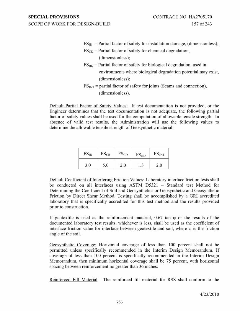
SPECIAL PROVISIONS CONTRACT NO. HA2705170 SCOPE OF WORK FOR DESIGN-BUILD 157 of 243
4/23/2010
FSID = Partial factor of safety for installation damage, (dimensionless); FSCD = Partial factor of safety for chemical degradation,
(dimensionless); FSBD = Partial factor of safety for biological degradation, used in
environments where biological degradation potential may exist, (dimensionless);
FSJNT = partial factor of safety for joints (Seams and connection), (dimensionless).
Default Partial Factor of Safety Values: If test documentation is not provided, or the Engineer determines that the test documentation is not adequate, the following partial factor of safety values shall be used for the computation of allowable tensile strength. In absence of valid test results, the Administration will use the following values to determine the allowable tensile strength of Geosynthetic material:
FSID FSCR FSCD FSBD FSJNT
3.0 5.0 2.0 1.3 2.0
Default Coefficient of Interfering Friction Values: Laboratory interface friction tests shall be conducted on all interfaces using ASTM D5321 – Standard test Method for Determining the Coefficient of Soil and Geosynthetics or Geosynthetic and Geosynthetic Friction by Direct Shear Method. Testing shall be accomplished by a GRI accredited laboratory that is specifically accredited for this test method and the results provided prior to construction. If geotextile is used as the reinforcement material, 0.67 tan φ or the results of the documented laboratory test results, whichever is less, shall be used as the coefficient of interface friction value for interface between geotextile and soil, where φ is the friction angle of the soil. Geosynthetic Coverage: Horizontal coverage of less than 100 percent shall not be permitted unless specifically recommended in the Interim Design Memorandum. If coverage of less than 100 percent is specifically recommended in the Interim Design Memorandum, then minimum horizontal coverage shall be 75 percent, with horizontal spacing between reinforcement no greater than 36 inches.
Reinforced Fill Material. The reinforced fill material for RSS shall conform to the

SPECIAL PROVISIONS CONTRACT NO. HA2705170 SCOPE OF WORK FOR DESIGN-BUILD 158 of 243
4/23/2010
following:
Sieve Size Percent Passing
2" 100
No. 4 100 - 20
No. 200 0 - 30
Where the PI shall be less than 5, when tested in accordance with T 90 and the pH shall be in the range of 3 to 9 when tested in accordance with AASHTO T 289. AASHTO A-2-6, A-2-7, A-4, A-5, A-6, and A-7 materials are not acceptable as reinforced fill material. Sodium Sulfate soundness loss shall be less than 30 percent after four cycles when tested according to T 104. The angle of internal friction (φ), and the effective angle of internal friction (φ') of the reinforced fill material shall be 32 degrees or greater. The shear strength parameters will be determined using one of the following: 1) D 3080 sheared at a displacement rate of 0.003 in/min or lower to allow adequate drainage or 2) D 4767 (CU) triaxial tests with the pore pressure measured to determine the effective strength parameters.
3.14.03.10 Design of Permanent Cut Slopes
Geotechnical analyses of soil cut slopes shall be performed to assess soil slope stability along new and existing roadway cuts. Potential circular and wedge type failure modes shall be analyzed for each soil cut and each slope and orientation. Slope stability analyses shall be conducted using limit equilibrium methodologies performed using a computer program such as PCSTABL, ReSSA or StedWIN. The Modified Bishop, simplified Janbu, Spencer, or other widely accepted slope stability methods shall be used for rotational and irregular surface failure mechanisms. Soil parameters based upon valid testing requirements shall be used. At a minimum, three laboratory test results shall be required to confirm the soil parameters. Shear strength testing shall be performed by an AMRL certified laboratory. The testing program shall be acceptable to the Administration. Permanent soil cut slopes shall be no steeper than 2H: 1V with a minimum factor of safety of 1.5 including surficial stability. In the absence of required right-of-way, the cut slope shall be engineered through the use of a toe wall, soil nail wall or other engineering technique. Cut slopes (2H:1V) in excess of 20 feet in height shall include a bench at least 10-feet in width at middle height of the slope. Drainage and erosion control provisions and means to control seepage shall be incorporated in the design and construction of the cut slopes. The Design-Builder shall have a record of water levels and the slope stability calculation

SPECIAL PROVISIONS CONTRACT NO. HA2705170 SCOPE OF WORK FOR DESIGN-BUILD 159 of 243
4/23/2010
shall model the effect of seepage in the slope stability calculations. The seepage line shall be intercepted with the use of slope drains or horizontal drains or any other techniques to enhance the stability of cut slopes.
3.14.03.11 Design of Ground Mounted Noise Barrier Foundations
There are no noise barriers on this project.
3.14.03.12 Design of Foundations for Traffic and ITS Structures
See “Deep Foundations” and Standard #5 for design requirements for deep foundations for sign structures, light poles and all other ancillary ITS components, including but not limited to cameras, cabinets and traffic poles. Refer to “Shallow Foundations” for design requirements for shallow foundations.
3.14.03.13 Design of Subgrade for Pavements
The Top of Subgrade shall be identified by the Design-Builder on the pavement details. Any material placed above the Top of Subgrade shall be considered part of the pavement structure. Any material placed below or other work below Top of Subgrade shall be considered a subgrade improvement. The minimum design subgrade resilient modulus (Mr) at the Top of Subgrade shall be as specified in the Pavement and Geotechnical Data Report. When the native soils are not capable of providing the minimum design strength, a subgrade improvement strategy shall be included in the pavement design to reach the minimum strength requirement at the Top of Subgrade. The Design-Builder shall specify the design subgrade strength, planned subgrade improvements, and as-needed subgrade improvements in the Interim Pavement Report. The same design subgrade strength value shall be used throughout the entire area of each roadway element. In the case that a subgrade improvement is used throughout a significant portion of a roadway element, it shall be shown in the pavement details. The Project shall be test rolled in accordance with Section 204.03.01(c) of the Standard Specifications for Construction and Materials. Passing test rolling shall signify that a section of subgrade has reached a stable construction platform and that the minimum subgrade strength, as specified in the Pavement and Geotechnical Data Report, has been achieved at the Top of Subgrade. Test rolling records and field notes shall be required to confirm the minimum subgrade strength was achieved and shall be included in the Final Pavement Report. In the case that the Top of Subgrade does not pass test rolling, the Design-Builder shall improve the failed area to a point that it meets or exceeds the minimum required design subgrade modulus specified by the Design-Builder in the Interim Pavement Report. Additional test rolling of the failed area shall be performed after improvement to verify the minimum required design subgrade modulus has been achieved at the Top of Subgrade. The Design-Builder may elect to use a design Mr value greater than the minimum requirement specified in the Pavement and Geotechnical Data Report. A design subgrade

SPECIAL PROVISIONS CONTRACT NO. HA2705170 SCOPE OF WORK FOR DESIGN-BUILD 160 of 243
4/23/2010
strength value used in the pavement design that is greater than minimum required shall be supported by the Design-Builder with historical performance results and design documentation in the Interim Pavement Report. The maximum allowable values for subgrade strengths at the Top of Subgrade are specified in the Pavement and Geotechnical Data Report, regardless of the subgrade improvement. A design subgrade strength value greater than the minimum requirements shall be field verified by the Design-Builder during construction through test data collected using a falling weight deflectometer (FWD) on the prepared Top of Subgrade. The FWD test set-up, load packages, test spacing, and analysis shall be as specified in the Construction of Pavement Subgrade section of the Geotechnical Performance Specification. The Design-Builder shall improve the subgrade area for each data collection point that FWD testing indicates the in-place Mr value is less than the design value specified by the Design-Builder. The subgrade improvement of the failed area shall result in the subgrade strength meeting or exceeding the minimum required design subgrade modulus specified by the Design-Builder in the Interim Pavement Report. Additional FWD testing of the failed area shall be performed after improvement to verify the minimum required design subgrade modulus has been achieved at the Top of Subgrade.
3.14.03.14 Design of Jack and Bore or Tunneling
The Design-Builder shall submit for approval working drawings and a written report, including computations, describing in detail the proposed jacking or tunneling method. The submittal shall also describe all aspects of the jacking or tunneling operation, including but not limited to the size and location of working and receiving shafts or pits, sizes and wall thicknesses of casing pipes, the method of dewatering, the method of removing earth material, and the method of installing and advancing and supporting the concrete storm drain pipe. The submittal shall also provide details of the backstop method, the shaft base material, the methods for protecting utilities in the work area, the type of cutter head, the method of monitoring and controlling line and grade, the configuration of traffic control and protective devices and measures, the method of detecting surface movement, and the method and the material proposed to fill voids created by the operations.
Once approved, any modifications to any aspect of the methods of construction, operations, materials, equipment, etc. shall be subject to the approval by the Administration before being implemented.
3.14.03.15 Jack and Bore or Tunneling Construction
If an obstruction is encountered during installation that stops the forward progress of the operation, the Engineer shall be notified immediately. If the Engineer determines that it is not possible to advance the pipe any further, the operation will be discontinued, and the Design-Builder shall propose alternative(s) for completing the work for review and

SPECIAL PROVISIONS CONTRACT NO. HA2705170 SCOPE OF WORK FOR DESIGN-BUILD 161 of 243
4/23/2010
approval. Alternatives could include using different tools and/or methods to advance the casing, relocating the casing (subject to geometric and hydrologic constraints, or possibly other options. Any completed portion(s) of the pipes shall be backfilled with flowable backfill or as otherwise directed by the Engineer. Augers, cutters, and related equipment shall be configured so as to be removable from within the pipe in the event a casing, or portion thereof, must be abandoned. If water is encountered during equipment set up or pipe installation, a dewatering system shall be employed. Dewatering shall be performed in such a way as to minimize the removal of soil particles. All water removed by dewatering operations shall be delivered to an approved sediment control device. Pumps of sufficient capacity to handle the flow shall be operated and attended on a 24-hour basis until, in the judgment of the Engineer, their operation can be halted. Perform dewatering in accordance with practices that are acceptable to MDE. All jacking shafts or pits shall be protected by temporary precast concrete traffic barriers and the sequencing of the jacking operations shall conform to the Maintenance of Traffic Plans and be approved by the Engineer. All operations shall be conducted so as not to interfere with, interrupt or endanger the operation of traffic. All jacked and bored steel casing pipes shall be installed to within 3 inches of the grades and 6 inches of the lines shown on the Plans. Coordinate the jacked steel casing pipe installations with the storm drain pipes alignment and grade. Where augers or similar devices are used, the overcut of the cutting head shall not exceed the outside diameter of the pipe by more than 3/4-inch. For hand mining, no overcut will be permitted. Blasting will not be permitted and jacking operations shall produce no upheaval, settlement, cracking, movement or distortion of the existing roadbed or other facilities. All shafts and pits shall be backfilled according to the Contract Documents to meet the proposed grades and maintenance of traffic requirements, if applicable.
3.14.04 CONSTRUCTION
The Design-Builder is responsible for any and all damage (including, but not limited to settlement and vibrations) to property, structures, or utilities, both inside and outside of the State Right-of-Way, caused by the Work on the Project, and shall appropriately mitigate for these damages.
3.14.04.01 Temporary Support of Excavation
Temporary support of excavation shall be designed in accordance with all applicable OSHA standards and AASHTO requirements including, but not limited to, the appropriate lateral earth pressures, hydrostatic pressure, surcharges and construction loading. Detailed design of

SPECIAL PROVISIONS CONTRACT NO. HA2705170 SCOPE OF WORK FOR DESIGN-BUILD 162 of 243
4/23/2010
all components shall be completed by the Design-Builder, including but not limited to, temporary decking, sheeting, bracing and tie-backs.
The Design-Builder shall comply with additional requirements regarding the design, review and approval of temporary support of excavation that may be outlined in bridge plans included in this RFP.
3.14.04.02 Utilities
See TC-3.15, Utility Design and Location Criteria Performance Specification. The Design-Builder shall identify all new and existing utilities crossing embankments, evaluate settlement impacts on these lines, and evaluate the impacts of abandoned lines on settlements.
The Design-Builder shall design new and relocated utilities to accommodate the anticipated settlements, to verify utilities operate effectively during and after construction as well as to satisfy the requirements of the utility owner.
New utilities shall not be placed within nor shall existing utilities remain within the pavement section. Abandoned utilities will not be allowed within the pavement section and shall be removed prior to placement of the pavement section. Utilities of any size that fall within 3 feet below the pavement section (below subbase) shall be relocated and the existing utility shall be removed. Other utilities shall be removed or abandoned as follows:
DEPTH UTILITY DIAMETER METHOD OF ABANDONMENT
0-feet to 3-feet All sizes Remove 3-feet to 15-feet < 8-inches Plug Ends 3-feet to 15-feet >= 8-inches Fill with Flowable Fill 15-feet or more < 24-inches Plug Ends 15-feet or more >= 24-inches Fill with Flowable Fill
3.14.04.03 Construction of Foundations
Construction noise levels shall conform to the requirements outlined in the Environmental Performance Specification. Ground consolidation, existing structure settlements, and disturbance to local residents due to the installation of deep foundations shall be maintained within limits acceptable to the Administration.
3.14.04.03.01 Shallow Foundations
After excavation, the Design-Builder’s Geotechnical Engineer and the Administration’s Geotechnical Engineer shall verify that the exposed subgrade is
SPECIAL PROVISIONS CONTRACT NO. HA2705170 SCOPE OF WORK FOR DESIGN-BUILD 163 of 243
4/23/2010
suitable for the calculated toe-pressures exerted by the proposed abutment or fill-type retaining wall. The Administration shall require in-situ testing to verify the required bearing values.
3.14.04.03.02 Deep Foundation Testing and Monitoring
Field-testing shall be performed for deep foundations to evaluate foundation capacity and integrity, to verify design assumptions, to determine foundation installation characteristics, to evaluate the pile driving system performance, and to establish foundation depths. The deep foundation testing and monitoring shall include all necessary test piles or shafts, dynamic testing, static load testing, non-destructive integrity testing, and quality control testing.
At least 30 working days prior to driving piles, the Design-Builder shall present the results of wave equation analysis of piles (WEAP) on the hammer-pile-soil systems proposed for the Project. The WEAP analysis shall be performed for all hammers proposed for use and for each Project element with driven pile foundations. The Administration may provide written comments to proposed hammers based upon the results of the WEAP analysis.
A pile driving analyzer (PDA) shall be used to determine if each hammer is delivering the energy required by the WEAP analysis. Each hammer used to drive test piles and production piles shall deliver a minimum of 45 percent of the rated hammer energy. Foundation testing and monitoring shall be performed on both test and production deep foundations, and shall be located so that they will address all conditions of foundation type, capacity and soil conditions encountered. All PDA equipment, testing, recording and reporting shall be performed in accordance with ASTM D-4945 Standard Test Method for High Strain Dynamic Testing of Piles. CAPWAP shall be utilized to determine the as-built pile capacity from the PDA data. As a minimum, the first pile driven for each substructure unit shall be a PDA test pile. Additional piles may be PDA piles depending upon the Design-Builder’s selected level of construction control and the corresponding Factors of Safety, in accordance with AASHTO Table 4.5.6.2A.
The Design-Builder shall prepare and submit a detailed description of the proposed deep foundation testing and monitoring programs. The description shall include detailed specifications and plans presenting the foundation type, test type, purpose, number, location, and procedures for each test, and the recording and reporting procedures. The number, location, type, procedures, and extent of testing of the deep foundations shall be subject to review by the Administration. Testing and monitoring of deep foundations shall be in accordance with the applicable ASTM and AASHTO specifications.
Static load tests performed on piles or drilled shafts shall be in accordance with the ASTM D-1143 or AASHTO. The Design-Builder may also submit for review the use

SPECIAL PROVISIONS CONTRACT NO. HA2705170 SCOPE OF WORK FOR DESIGN-BUILD 164 of 243
4/23/2010
of either the Osterberg Load Cell or the Statnamic Testing arrangement. The number and locations of static deep foundation load tests shall be determined by the Design-Builder, but shall be performed at locations representative of the different subsurface conditions, foundation types, foundation capacities, and foundation depths. At least 30 working days prior to driving load-test piles, the Design-Builder shall submit proposed configuration for pile load tests, including the structural calculations for the reaction beam, piles, and connections; calibration results for the loading jack, load cell, and gages before the tests; and other pertinent details.
All foundation field-testing results shall be compared with the design capacity and proposed Factor of Safety. Where field testing results reflect a lower than required Factor of Safety, the Design-Builder shall prepare a Remedial Action Plan for review by the Administration.
3.14.04.03.03 Drilled Shaft Inspection and Integrity Testing
The Design-Builder shall assign one full-time inspector for each drilled shaft installation rig in use for foundations, retaining walls and other critical structures. The Design-Builder shall also assign inspectors for at least 15% of drilled shaft installation for ground mounted Noise Barrier Panels. At least 30 working days prior to drilled shaft installation, the Design-Builder shall present the qualifications for each proposed drilled shaft inspector to verify the following required minimum qualifications:
A) At least one year of drilled shaft installation experience working under the supervision of a licensed civil engineer specializing in foundations and geotechnical engineering; or
B) At least 2 months of inspection experience and attendance at the FHWA-NHI Drilled Shaft Foundation Inspection Course (#132070).
C) A Down Hole Camera may be required to inspect the drill shaft hole in order to ensure that the drill hole is stable and to verify that there is no presence of any loose material at the bottom of drilled hole.
Integrity testing consisting of ASTM D-6760 Crosshole Sonic Logging (CSL) or ASTM D-5882 Low Strain Pulse Echo Methods shall be performed on 25% of foundations.
3.14.04.03.04 Pile Driving Records
The Design-Builder shall create and maintain a hand-written record of pile driving. For the entire length of each pile, the Design-Builder shall record blows and estimated delivered energy (hydraulic hammers) or stroke (diesel hammers) for each foot of penetration. The Design-Builder shall record the start and stop times to the nearest minute and record any stoppages in field pile driving.

SPECIAL PROVISIONS CONTRACT NO. HA2705170 SCOPE OF WORK FOR DESIGN-BUILD 165 of 243
4/23/2010
Prior to beginning the placement of reinforcing steel around the piles, and/or prior to beginning any backfilling around the piles, the Design-Builder shall present for review and comment the complete driving records including tolerance measurements for all piles in each pile group and the PDA and CAPWAP results.
3.14.04.03.05 The Design-Builder’s Pile Inspector and Geotechnical Engineer
The Design-Builder shall assign one inspector for each pile-driving rig in use. At least 30 working days prior to pile driving, the Design-Builder shall submit the required qualifications for each pile driving inspector who has the following minimum qualifications:
A) At least one year of pile driving inspection experience while working under the supervision of a licensed civil engineer specializing in foundations and geotechnical engineering; or
B) At least 2 months of pile driving inspection experience and successful completion of FHWA-NHI Driven Pile Foundation Inspection course (#132069)
The Geotechnical Engineer shall either be on-site during the driving of the first pile at each support (monitored with PDA) and until sufficient data is gathered to establish appropriate driving criteria for each support; or be in direct telephone contact with the PDA operator and the inspector observing the pile driving. The Geotechnical Engineer shall be notified immediately if any unusual or otherwise unanticipated pile driving conditions are encountered, including if the piles are driven out of the tolerances specified by SHA Standard Specification for Construction and Materials Section 410.03.07.
Based upon the installation and testing data, the Design-Builder’s Geotechnical Engineer shall validate that the piles were adequately driven. If not adequately driven, the Design-Builder’s Responsible Engineer shall recommend an appropriate resolution for review by the Administration.
3.14.04.04 Mechanically Stabilized Earth Retaining Wall Construction
Maryland Size No 57 stone shall be used within the reinforced mass for all preapproved MSE retaining walls.
3.14.04.05 Fill Embankment Construction
The Design-Builder shall submit the source and material properties of all fills proposed for use, including the results of gradation tests, plasticity tests and shear strength testing.

SPECIAL PROVISIONS CONTRACT NO. HA2705170 SCOPE OF WORK FOR DESIGN-BUILD 166 of 243
4/23/2010
All laboratory tests shall be performed in accordance with the appropriate ASTM/AASHTO test methods. The bearing capacity of the embankment foundation shall be validated by the requirements of Section 204 of Maryland SHA’s Standard Specifications for Construction and Materials and documented by the Design-Builder’s Geotechnical Engineer prior to initiating construction. The Design-Builder should provide adequate drainage and dewatering measures to control surficial and ground water within the construction site. Adequate drainage should be provided to prevent ponding of water in the excavation and minimize any increase in moisture content of the in-situ soils. Sheet flow across the slope face will not be permitted during construction or for the permanent condition until vegetation is established on the face of the slopes.
3.14.04.05.01 Settlement of Embankments
Prior to releasing any fills and/or surcharges and proceeding with subsequent construction activities, the Design-Builder shall compile, and submit as per TC 3.14.04.11 “Geotechnical Instrumentation”, any settlement data, including proof that all settlements necessary have occurred.
3.14.04.05.02 Embankment Construction Near Existing Structures
Where embankments or walls are to be constructed in the vicinity of existing structures, the Design-Builder shall develop and implement a program for performing preconstruction surveys and monitoring movement of structures that shall include the following:
A) Estimate the settlement influence zone from embankment and construction loads that includes settlements in excess of ½-inch;
B) Site reconnaissance to determine the sensitivities of adjacent structures to settlement;
C) Identification of site-specific facilities that may be adversely affected by settlement;
D) Procedures to mitigate and to compensate property owners affected by settlement/movement resulting from construction activities.
3.14.04.06 Construction of Top-Down Walls (Cut Walls)
Where tie-backs, or ground anchors are required for resistance of lateral loads, the elements shall be constructed in accordance with FHWA “Geotechnical Engineering Circular No. 4: Ground Anchors and Anchored Systems”. This includes adhering to material requirements, components, installation and proof-testing procedures as described in Appendix E of the above references and AASHTO Division II - Construction.

SPECIAL PROVISIONS CONTRACT NO. HA2705170 SCOPE OF WORK FOR DESIGN-BUILD 167 of 243
4/23/2010
3.14.04.07 Culvert Construction
See “Construction of Foundations”, above.
3.14.04.08 Construction of Noise Wall Foundations
Not applicable as there are no noise walls in this project.
3.14.04.09 Construction of Foundations for Sign Structures
See “Construction of Foundations” above.
3.14.04.10 Construction of Pavement Subgrades
The Design-Builder shall be responsible for construction of a suitable and stable subgrade on which to place the pavement section. The Top of Subgrade shall be test rolled prior to placing the base course in the Pavement Section(s). Any movement in the Top of Subgrade during test rolling shall be an indication of unstable subgrade or the presence of unsuitable material. Unstable or unsuitable areas shall be treated as recommended in the Final Geotechnical Report. After treatment, the area shall again be test rolled. Any area still showing movement shall receive additional corrective treatment. In the presence of surface water and/or within 3 feet below the proposed subgrade, the Design-Builder shall engineer the subgrade (Drainage Blanket, Subgrade drain…) to handle the water and moisture conditions. In case of pumping of subgrade the D-B shall stabilize the subgrade prior to placement of sub base or base material. FWD testing shall occur after the Design-Builder has constructed and properly compacted the Top of Subgrade. The Design-Builder shall provide testing program guidelines and vendor qualifications for FWD testing in the Final Pavement Report. The FWD testing program for subgrade resilient modulus shall adhere to the following test parameters and requirements:
A. ASTM D 4694 shall be followed in the data collection with the FWD.
B. No data collection shall occur on a frozen subgrade and ambient air temperature shall be greater than 40 degrees F.
C. The Design-Builder shall use a FWD testing vendor that can demonstrate at least 3 years worth of experience in FWD testing and analysis and submit that information with the Final Pavement Report;

SPECIAL PROVISIONS CONTRACT NO. HA2705170 SCOPE OF WORK FOR DESIGN-BUILD 168 of 243
4/23/2010
D. Load plate radius = 9 inches;
E. Minimum load applied = 4,000 pounds, maximum load = 9,000 pounds; and
F. All FWD data shall be collected and stored electronically and submitted as a package with the data analysis to verify subgrade resilient modulus strengths.
The FWD test set-up, load packages, test spacing, and analysis shall be as specified in the following table:
Any
FWD test location of a roadway element that does not meet the minimum subgrade strength specified by the Design-Builder at the Top of Subgrade shall be improved to a point that it reaches or exceeds the minimum subgrade strength specified by the Design-Builder. The 100 yd2 of prepared subgrade that does not meet or exceed the design strength shall be improved for any failing FWD test point. Improvements shall be made to ensure that the subgrade strength at the Top of Subgrade reaches or exceeds the
Item Requirements Comments Sensor Spacing 0”, 12”, 18”, 24”, 36”,
48”, 60” Additional sensors are acceptable
Load Package AA1B2 A = Seating Drop of 6,000 lbs. B = Seating Drop of 9,000 lbs. 1 = Recorded Drop of 6,000 lbs. 2 = Recorded Drop of 9,000 lbs.
Test Pattern One per every 100 yd2 of prepared subgrade in the mainline and shoulder, minimum of 5 tests.
Analysis Mr = 1.5pa ∆z
p = applied load (psi) a = radius of load plate (in) ∆ z = measured deflection (in)

SPECIAL PROVISIONS CONTRACT NO. HA2705170 SCOPE OF WORK FOR DESIGN-BUILD 169 of 243
4/23/2010
minimum subgrade strength specified by the Design-Builder. The limit of improvement may be modified through more frequent and additional FWD testing in the travel lane or shoulder in question.
3.14.04.11 Geotechnical Instrumentation
The Design-Builder shall prepare and submit instrumentation monitoring plans to either monitor facilities that may be affected by construction activities or to monitor field performance of specific construction elements in accordance with the following criteria and requirements. The Design-Builder’s Instrumentation Engineer shall have a minimum of 5 years of experience in planning instrumentation programs, monitoring, analyzing instrumentation data and providing control and threshold values.
A) The extent of the monitoring program will depend on the size and type of the facilities. The instrumentation program shall be implemented to monitor potential settlement, stability of fill or cut slopes and stability of surrounding structures;
B) The type and distribution of instrumentation shall demonstrate an understanding of the need, purpose and advantages of using each proposed instrument;
C) The plan shall include consideration of environmental effects such as temperature, rain, sun, wind, corrodibility, and electromagnetic wave interference;
D) Responsibilities for the instrumentation plan, procurement, installation, recording, maintenance and protection shall be the Design-Builders;
E) The instrumentation plan will provide construction-related control information and accommodate the collection of long-term performance data;
F) Test installations may be performed to demonstrate the compliance and acceptability of instrumentation in relation to the Contract requirements;
G) If instruments fail or are damaged they shall be replaced at no cost to the Administration and the Design-Builders Geotechnical Engineer may require that all work cease in the area to be monitored by the instruments, with the concurrence of the Administration;
H) Monitoring shall be initiated a minimum of 15 days prior to construction of the features being monitored to establish baseline readings; and,

SPECIAL PROVISIONS CONTRACT NO. HA2705170 SCOPE OF WORK FOR DESIGN-BUILD 170 of 243
4/23/2010
I) The results of the vibration measurements shall be used to develop attenuation curves for predicting vibrations at varying distances from the source.
J) Qualifications of instrumentation personnel should be listed. K) The Design-Builder shall provide calibration of all data acquisition
equipment used to collect the required instrumentation data. L) A set of full size plans and cross sections of the area covered by the report, M) Copies of any reports or references referred in the report.
3.14.04.11.01 Monitoring Facilities for Effects of Construction Activities
The Design-Builder shall prepare instrumentation plans, where appropriate, to monitor existing facilities, temporary construction support structures and in-progress construction of permanent facilities for effects of construction activities such as excavation by blasting, pile driving and nearby construction equipment traffic. Monitoring may include vibrations, ground accelerations, tilt or rotation, and vertical and lateral movement during and after construction. The Design-Builder shall prepare a report detailing the proposed program of instrumentation and monitoring, establishing threshold values of monitored parameters, and describing the response plans that will be implemented when threshold parameters are exceeded. After the Administration’s review and comment on the instrumentation plan, threshold values and response plan, the Design-Builder shall provide, install and monitor the instrumentation during and after construction and interpret the data. Construction instrumentation monitoring reports shall be submitted to the Administration prior to opening the instrumented work for subsequent construction. Corrective actions shall be taken where the instrumentation data so warrant. The instrumentation plan shall provide that potentially affected facilities are protected against damage due to the construction of the Work. Limiting values of movement (horizontal and vertical), vibration and acceleration for each facility within the zone of influence of the Work shall be established by the Design-Builder. To establish these limiting values, the designer shall consider the nature of buildings and facilities within the sphere of influence of the construction activities, including their use, foundation systems, structural design and current condition. Records of facilities, where available, shall be examined during the design stage and, where no record exists, assessments shall be made and clearly stated. These assessments shall be subject to verification at the commencement of the construction phase prior to the adjacent construction activity. In addition to the instrumentation plan, the Design-Builder shall conduct Preconstruction and Postconstruction surveys for nearby structures and facilities that may be affected by construction activities. The minimum distance for Preconstruction and Postconstruction surveys is 500 feet from existing facilities, temporary construction support structures and

SPECIAL PROVISIONS CONTRACT NO. HA2705170 SCOPE OF WORK FOR DESIGN-BUILD 171 of 243
4/23/2010
construction of permanent facilities to construction activities such as excavation by blasting, pile driving, and nearby construction equipment traffic.
3.14.04.11.02 Instrumentation for Monitoring Field Performance of Construction Elements
The Design-Builder shall prepare instrumentation plans, where appropriate, to monitor field performance of specific construction elements such as settlement, lateral earth movement, rotation of structural elements and changes in groundwater. The instrumentation and monitoring program shall include appropriate types and quantities of monitoring instruments capable of measuring horizontal and vertical movements, tilt/rotation of structural elements, soil pore pressures and vibrations, as applicable. Instrumentation that may be used in monitoring programs to control and assist design and construction include, but are not limited to:
A) Piezometers and observation wells;
B) Inclinometers;
C) Survey stations on structures and at ground level locations;
D) Tiltmeters;
E) Deep and shallow settlement points and extensometers;
F) Strain and load-measuring devices; and
G) Seismographs;
H) Optical survey. I) Time Domain Reflectometer (TDR)
The Design-Builder shall not release monitored elements for subsequent construction until completed monitoring reports have been submitted.
3.14.05 SUBMITTALS

SPECIAL PROVISIONS CONTRACT NO. HA2705170 SCOPE OF WORK FOR DESIGN-BUILD 172 of 243
4/23/2010
All submittals shall be subject to review and approval as per TC Section 3.06.21.1.
The Design-Builder shall submit the following geotechnical reports and documents at various stages of the project for individual project elements or groups of elements for approval by the Administration. Copies of these submittals shall also be sent to the Project Engineer and the Office of Materials Technology (OMT). Office of Materials Technology is located at
Office of Materials Technology 7450 Traffic Drive Hanover, MD 21076 Phone: 1-866.926.8501 (Toll free)]
3.14.05.01 Geotechnical Planning Reports
The Design-Builder shall prepare Geotechnical Planning Reports for individual Project elements or groups of Project elements based upon the design/construction priority and/or sequence of construction. The Geotechnical Planning Reports shall include a detailed method statement describing the general philosophy and methods of investigation, preliminary design and analysis and selection of the anticipated means of construction for the included Project elements. The method statement shall indicate how material and design details are chosen to match selected construction methods and construction details and the soil, rock, and groundwater environment for the site. For each Geotechnical Planning Report, the Design-Builder shall include the following technical information, as a minimum:
a) Description of geology and various ground types to be encountered along the alignment;
b) A description of the geotechnical information that was collected and analyzed in developing the Design-Builder’s Geotechnical Planning Report;
c) Assessment of the engineering properties of all soil types, including the expected average and range of soil strengths and deformation properties and the preliminary design parameters for all soil and rock types;
d) A narrative describing the interpretation of the pertinent geotechnical data used as a basis for preliminary selection, design, and installation of the proposed foundation elements;
e) A description of the planned supplemental subsurface investigation (See “Design-Builders Subsurface Exploration”).
f) The Geotechnical Planning Reports shall define the investigation, engineering and design approach that will be followed in order to develop the most technically, and environmentally acceptable and durable foundations, cut and fill slopes, retaining structures, pavements, stormwater management, and geotechnical designs for the elements included in the Geotechnical Planning Report.

SPECIAL PROVISIONS CONTRACT NO. HA2705170 SCOPE OF WORK FOR DESIGN-BUILD 173 of 243
4/23/2010
g) The Geotechnical Planning Report should also include a set of full size or half size plans and cross sections of the areas covered by the report, and a copy of any reports or references referred in the report.
The Geotechnical Planning Reports shall be prepared, signed and sealed by a Professional Engineer licensed in the State of Maryland. This Geotechnical Planning Report shall be submitted to the Administration 30 days prior to mobilization. Prior to mobilization, the Design-Builder and the Administration shall meet to discuss the contents of the Geotechnical Planning Reports and present the Administration’s review written comments.
3.14.05.02 Interim Design Memoranda
The Design-Builder shall prepare Interim Design Memoranda for individual Project elements or groups of Project elements consistent with the Geotechnical Planning Reports. The Interim Design Memoranda shall be submitted in accordance with “Submittals” in the Structures Performance Specification and shall include the following, at a minimum:
a) Description of the Project elements included in the Memorandum;
b) Locations of borings, rock coring, geophysical testing and other in-situ testing;
c) Field testing procedures;
d) Final typed boring logs updated with laboratory testing results;
e) Electronic copy of the gINT data of subsurface investigation data;
f) Results of any in-situ testing and geophysical testing;
g) A description of subsurface conditions, including groundwater, and subsurface profiles;
h) Results of laboratory tests;
i) Values assigned to soil parameters for design;
j) Descriptions of pertinent geotechnical analyses and designs;
k) Conclusions and recommendations for the specific Project elements;
l) Construction considerations such as blasting and vibration monitoring;
m) Level of construction control for deep foundations;
n) Instrumentation and monitoring requirements;
o) A set of full size plans and cross sections of the area covered by the report,
p) Copies of any reports or references referred in the report.
SPECIAL PROVISIONS CONTRACT NO. HA2705170 SCOPE OF WORK FOR DESIGN-BUILD 174 of 243
4/23/2010
3.14.05.03 Final Geotechnical Reports The Design-Builder shall prepare Final Geotechnical Reports for individual Project elements or groups of Project elements consistent with the Geotechnical Planning Reports and the Interim Design Memoranda prior to releasing constructed elements for subsequent work. The Final Geotechnical Reports shall include the following, at a minimum:
A. The corresponding Geotechnical Planning Report;
B. The corresponding Interim Design Memorandum;
C. Locations and results of borings, rock coring, geophysical testing and other in-situ testing;
D. A detailed description of geological and subsurface conditions for each Project element (including a description of site stratigraphy);
E. Field investigation procedures;
F. A description of groundwater conditions;
G. Results of laboratory tests;
H. Values assigned to all applicable soil parameters for design;
I. All pertinent data and complete discussions of all geotechnical analyses and design;
J. All relevant design calculations and computer program results checked and initialed by a Professional Engineer licensed in the State of Maryland;
K. Conclusions and recommendations for foundation types for structures, embankments, cut slopes, retaining walls, ground improvement, requirements for backfill materials;
L. Groundwater problems encountered, means of dewatering and/or other solutions;
M. Designs for support of excavation;
N. Results of instrumentation and monitoring and post-construction monitoring summaries;
O. Potential settlement problems; and
P. Potential stability problems and analysis results;
Q. A set of full size plans and cross sections of the area covered by the report,
R. Copies of any reports or references referred in the report. For each of the following Project elements, the Design-Builder shall submit the following items with the Final Geotechnical Reports.
Q. Foundations
1) Individual pile and pile group design calculations including axial and lateral capacity for the pile type, size, and length to achieve the required capacities (including any effects of liquefaction and downdrag);

SPECIAL PROVISIONS CONTRACT NO. HA2705170 SCOPE OF WORK FOR DESIGN-BUILD 175 of 243
4/23/2010
estimated pile and pile group settlement;
2) Shallow foundations calculations including allowable bearing capacity, estimated differential and total settlements, and rotations; and
3) Calculations of embankment settlement (magnitude and time rate) and downdrag forces on the piles, depths to zero or negligible settlement, and the proposed means to mitigate the downdrag.
R. Retaining Walls
1) Wall design calculations including the results of the global and internal stability analyses; analyses of total, differential, and secondary settlements; and, calculations for analyses of sliding, overturning, and bearing pressure for live and seismic loadings;
S. Embankments
1) The results of the slope stability analyses, including external loading from live and seismic loading, the recommended side-slopes of all embankments and the search limits and the most critical failure surface should be highlighted; input and output files should be included.
2) The results of settlement analyses, including predictions of the magnitude and duration of primary, secondary, and post-construction settlements;
3) The results of the liquefaction analyses and the proposed methods of mitigation for any location deemed necessary to protect the integrity of bridges and adjacent walls;
4) The proposed method(s) of protecting and abandoning utilities.
T. Cut Slopes
1) The results of the slope stability analyses, including external loading from live and seismic loading, and the recommended side-slopes of all cuts;
2) Evaluation of rock cut slopes shall clearly describe the rock bedding Characteristics, including strike and dip and a detailed description of the analysis completed to assure stability. Software and references used shall be from industry accepted sources, preferably Government Agencies such as the FHWA or the Army Corps of Engineers.
U. Subgrades for Pavements
1) The results of all subgrade improvement testing including Falling Weight Deflectometer test results.
V. Instrumentation

SPECIAL PROVISIONS CONTRACT NO. HA2705170 SCOPE OF WORK FOR DESIGN-BUILD 176 of 243
4/23/2010
1) All items included in TC 3.14.04.11 “Geotechnical Instrumentation” above.

SPECIAL PROVISIONS CONTRACT NO. HA2705171 SCOPE OF WORK FOR DESIGN-BUILD 177 of 243
4/23/2010
TC SECTION 3.15 UTILITY DESIGN AND RELOCATION CRITERIA 3.15.01 Utility Statement
3.15.01.01 General
The Design-Build Team’s attention is called to the requirements of Section GP-5.05, GP-7.13 and GP-7.17. 3.15.01.02 Utilities Within Project Limits
The Design-Build Team (DBT) is alerted to the presence of overhead and underground utilities including but not limited to water, sanitary sewer, gas, electric, communications, utility conduit, poles and house service connections that are located within the limits of the State Highway Administration (SHA) right of way and within the limits of the construction project. It is the responsibility of the DBT to avoid, protect, coordinate and relocate these utilities as necessary to maintain service, safety and project schedule with minimal disruption to the traveling public or utility customers. The DBT is responsible to coordinate with these utilities on the overall project design, schedule and construction. As it is impossible to determine how a DBT will perform certain operations or how much space will be needed to perform those operations, the relocations will be based on the utility companies’ safety and clearance requirements. It may be necessary for the DBT to utilize non-typical methods in some cases to avoid impacting utility facilities. Associated costs will be incidental to the overall contract lump sum.
The Design-Build Team shall incorporate and make provisions in the design for all existing and proposed utilities including relocations. The Design-Build Team shall establish and maintain ongoing coordination with utility owners after initial contact has been made by the Administration to fulfill the following requirements:
a. Obtain plans from the utility companies.
b. Assure adequate protection of their utilities.
c. Maintain utility service at all times during construction of the project.
d. Identify all potential conflict areas both overhead and underground and perform test pits to verify conflicts.
e. Incorporate and accommodate utility relocations in the schedule and sequence of
construction.

SPECIAL PROVISIONS CONTRACT NO. HA2705171 SCOPE OF WORK FOR DESIGN-BUILD 178 of 243
4/23/2010
f. Conduct alternative studies to avoid utility relocation.
g. All costs associated with additional utility relocations caused by changes to the design will be incurred by the DBT and not the Administration. Additional utility relocations will be coordinated with the utility company and District 4- Utility
h. Engineer of the State Highway Administration
i. Incorporate utility relocations in the schedule and sequence of construction.
j. Provide the construction associated with any utility service connections to existing and proposed Traffic Control Devices. The Design-Build Team shall be responsible for all conduits, manholes, cabling, meter cans, and disconnect switches as required by the utility to obtain the electrical utility connection. Monthly energy use charges and the final connection fees will be the responsibility of the Administration.

SPECIAL PROVISIONS CONTRACT NO. HA2705171 SCOPE OF WORK FOR DESIGN-BUILD 179 of 243
4/23/2010
Contact Information:
Mr. Steve Wallis City of Aberdeen 60 North Parke Street Aberdeen, MD 21001 Phone 410-272-1600
Mr. David Peplinski Harford County Department of Public Works Division of Water & Sewer 212 South Bond Street Bel Air, MD 21014 Phone 410-638-3300
BGE Gas
BGE Electric
Mr. Stephen O’Connor Verizon Maryland 99 Shawan Road Hunt Valley, MD 21030 Phone 410-393-6377
Mr. Eric Johnson Verizon Business 501 Wampanoag Trail 4th Floor Riverside, RI 02915 Phone 401-435-2742
Mr. Michael Pasquariello SHA DUE 320 West Warren Road Hunt Valley, MD 21030 Phone 410-229-2341
Mr. Daniel L. Singleton Comcast Cable 30 North Parke Street Aberdeen, MD 21001 Phone 410-612-0781

SPECIAL PROVISIONS CONTRACT NO. HA2705171 SCOPE OF WORK FOR DESIGN-BUILD 180 of 243
4/23/2010
3.15.01.03 Non-Impacted Utilities
Verizon Business (AT&T) maintains existing facilities within the limits of this project but are not anticipated to be impacted. Immediate notification shall be made by the DBT to the utility owner and the SHA District Utility Engineer (DUE) if a conflict with these utilities is identified. If the DBT impact these facilities, the DBT will be responsible to coordinate the necessary design and relocation at no additional cost to the SHA or the utility owner. 3.15.01.04 Utility Relocations By Others
Verizon Maryland, BGE Gas, BGE Electric and Comcast maintain facilities located within the limits of this project that have been found to be in conflict with SHA’s Phase 1 approved for construction plans and Phase 2 conceptual design. These impacts will be relocated by the utility owner concurrent to this project based on SHA’s Phase 1 approved for construction plans and Phase 2 conceptual design. Conceptual utility relocations plans are being provided on Projectwise for information purposes only. This information is based upon the utility owners’ plans and as-built drawings and on SHA’s Phase 1 approved for construction plans and Phase 2 conceptual plans. It is not field verified and the Administration makes no representation regarding the accuracy of the information. It is the responsibility of the DBT to coordinate these concurrent relocations with the DBT’s design, schedule and sequence of construction so that there are no delays to the utility relocations or SHA’s project. If the DBT cannot avoid conflict with relocated utilities, the cost of the redesign and relocation of those facilities shall be 100% the DBT’s responsibility.

SPECIAL PROVISIONS CONTRACT NO. HA2705171 SCOPE OF WORK FOR DESIGN-BUILD 181 of 243
4/23/2010
3.15.01.05 Utility Relocations by DBT
3.15.01.05.01 City of Aberdeen and Harford County Department of Public Works
The City of Aberdeen maintains Water and Sanitary Sewer facilities and Harford County Department of Public Works maintains Water facilities located within the limits of this project that have been found to be in conflict with SHA’s Phase 1 approved for construction plans and Phase 2 conceptual design. The DBT will be responsible for identifying all impacts to these water and sewer facilities within the limits of this project, perform test pits to verify conflicts, perform design alternative studies to remove or minimize these conflicts, design water and sewer relocation plans and coordinate and receive approvals from SHA and utility companies for relocation plans and construct water and sewer relocations. This includes scheduling meetings with each utility owner and SHA and maintaining ongoing coordination during the entirety of this contract. A conceptual water and sewer relocation plan based on SHA’s Phase 1 approved for construction plans and Phase 2 conceptual plan was developed. This conceptual plan is being provided on Projectwise for information purposes only. The DBT shall provide relocation design to each of the utility owners for review and approval.
The DBT shall incorporate and accommodate utility relocations in the schedule and sequence of construction.
3.15.01.05.02 SHA OOM – Underground Fiber Optic Cable
SHA OOM maintains Underground Fiber Optic Cable facilities located within the limits of this project that have been found to be in conflict with SHA’s Phase 1 approved for construction plans and Phase 2 conceptual design. The DBT will be responsible for identifying all impacts to these Underground Fiber Optic Cable facilities within the limits of this project, perform test pits to verify conflicts, perform design alternative studies to remove or minimize these conflicts, design Underground Fiber Optic Cable relocation plans and coordinate and receive approvals from SHA for relocation plans and construct Underground Fiber Optic Cable relocations. This includes scheduling meetings with SHA and maintaining ongoing coordination during the entirety of this contract.

SPECIAL PROVISIONS CONTRACT NO. HA2705171 SCOPE OF WORK FOR DESIGN-BUILD 182 of 243
4/23/2010
The DBT shall incorporate and accommodate utility relocations in the schedule and sequence of construction.
3.15.02 Relocation of City of Aberdeen Water and Sewer and Harford County Water Facilities
3.15.02.01 Description This work will consist of designing, furnishing and installing all new relocations and/or replacements of water and sanitary sewer mains and appurtenances owned by Harford County (County) and the City of Aberdeen (City) within the project limits which are impacted by the project. 3.15.02.02 Coordination with Other Work
The Design-Build Team shall coordinate the work on and location of the County’s and City’s facilities to avoid conflicts with work by others, including the Design-Build Teams roadway and drainage design. 3.15.02.03 Adherence to County Manuals
The latest edition of the Harford County Department of Public Works Division of Water and Sewer Standard Specifications and Details for Water Mains & Sewer Mains shall be adhered to with the exclusion of:
• The following General Provision Sections: o 2, 3, 4.B, 4.D, 4.F, 4.H-M, 5.A, 5.C, 5.D.4-6, 5.E.3, 5.F-N, 5.P,
5.Q, 6.A-J, 6.K.2, 6.L, 6.M, 7.A, 7.B.2-3, 7.B.6, 7.C-F, 8 and 9 • All “Method of Measurement” and “Basis of Payment” sections • Section 02012 – Test Pits • Section 02110 – Clearing and Grubbing • Section 02820 – Turf Establishment • Section 02830 – Sodding • Section 02850 – Soil Stabilization Matting • Section 02860 – Tree Protection • Section 02865 – Trees and Shrubs • Section 02870 – Fences
The latest edition of the Harford County Water and Sewer Design Guidelines and the City of Aberdeen “Approved List of Materials for Water and Sewer Construction” shall be adhered to. Upon conflicting requirements between any County Manual, City List and the Administration’s Standard Specifications for Construction and Materials, the higher standard will be implemented and the conflict will be remanded to the Administration, County and/or City for resolution. The DBT will be able to access the County Manuals via ProjectWise.
SPECIAL PROVISIONS CONTRACT NO. HA2705171 SCOPE OF WORK FOR DESIGN-BUILD 183 of 243
4/23/2010
3.15.02.04 Anticipated Impacted Water and Sanitary Sewer
Water mains owned by the County are known to be within the project limits. The following areas have been found to be in conflict with SHA’s Phase 1 approved for construction plans and Phase 2 conceptual plans:
1. FH – MD 715 RT Station 116+80± 2. 16”W – MD 715 LT Station 119+70± 3. 16”W – MD 715 RT Station 199+90± 4. 16”W – MD 715 RT Station 120+70± to 121+30± 5. FH – MD 715 RT Station 127+05± 6. 16”W – MD 715 RT Station 127+10± 7. 8”S – US 40 RT Station 1160+20± to 1173+45± 8. FH – US 40 RT Station 1162+70± 9. FH – US 40 RT Station 1167+75± 10. FH – US 40 RT Station 1172+60± 11. FH – US 40 RT Station 1177+65± 12. 16”W – US 40 RT Station 1181+55± to 1185+45± (including FH) 13. 16”W – US 40 RT Station 1194+05± to 1194+50± 14. 16”W – US 40 RT Station 1195+35± to 1195+75± 15. FH – US 40 RT Station 1197+95±
These water mains and sanitary sewer mains owned by the City are known to be within the project limits. The following areas have been found to be in conflict with SHA’s Phase 1 approved for construction plans and Phase 2 conceptual plans:
1. 10” Sanitary Force Main – MD 715 LT Station 107+15± to 109+40 ±
2. 12”W – Old Philadelphia Road RT Station 310+30± to 310+75± 3. FH – Old Philadelphia Road RT Station 314+70± 4. 12”W – Old Philadelphia Road RT Station 316+90± to 317+75± 5. 12”W – Old Philadelphia Road LT Station 318+70± to 322+55±
(including FH) 6. 8” S – Old Philadelphia Road Station 320+15±
3.15.02.05 Design
3.15.02.05.01 Preliminary Design Prior to beginning design the Design-Build Team shall:

SPECIAL PROVISIONS CONTRACT NO. HA2705171 SCOPE OF WORK FOR DESIGN-BUILD 184 of 243
4/23/2010
1. Consult with the County Division of Water and Sewer and the City Engineer Division and review as built information and other pertinent data.
2. Obtain such additional geotechnical and related information deemed necessary for performance of the work.
3. On the basis of the County’s design requirements, as determined upon consultation with the City and County, and as stated herein, prepare Preliminary Design Phase Documents consisting of a Concept and Preliminary Plan Approval Letter and Letter of Intent in accordance with the County’s Water and Sewer Design Guidelines.
4. Furnish the Preliminary Design Phase Documents, including any required Engineering Evaluation Reports, to the Administration for review by the County and City.
Administration and County and/or City will review the plan
submittals and return comments per TC Section 3.06.20.1.1, Review Timeframes.
3.15.02.05.02 Final Design
After written acceptance by the County and/or City of the Preliminary Design Phase Documents, the Design-Build Team shall:
On the basis of the accepted Preliminary Design Phase
Documents, prepare Construction Plans, showing the water main and sanitary sewer construction to be performed and furnished by the Design-Build Team in accordance with the County’s Water and Sewer Design Guidelines.
1. On the basis of the Construction Plans prepare an
item-by-item breakdown of the lump sum price for the proposed work. The item-by-item breakdown will be used to determine cost responsibilities between the Administration and the County and City.
2. Furnish Constructions Plans and the item-by-item breakdown to the Administration for review by the County and/or City.
Administration and County and/or City will review the plan
submittals and return comments per TC Section 3.06.20.1.1, Review Timeframes.
3.15.02.06 Materials

SPECIAL PROVISIONS CONTRACT NO. HA2705171 SCOPE OF WORK FOR DESIGN-BUILD 185 of 243
4/23/2010
Design-Build Team shall furnish all material. The Design-Build Team will procure materials referred to in the County Manuals as “to be furnished by the County” from manufacturers or equals approved by the County and City.
3.15.02.07 Construction After written acceptance by the County and City and the issuance of a construction permit by MDE, the Design-Build Team shall supervise, and direct the Construction, competently and efficiently, devoting such attention thereto and applying such skills and expertise as may be necessary to provide the construction in accordance with the requirements of the County and City, as determined upon consultation with the County and City and as stated herein. All construction activities shall be in accordance with the latest edition of the Harford County Department of Public Works Division of Water and Sewer Standard Specifications and Details for Water Mains & Sewer Mains, and the City of Aberdeen “Approved List of Materials for Water and Sewer Construction” with exceptions noted above.
3.15.02.07.01 Insurance The County and City shall be listed as an additional named insured on the policy acquired to fulfill the requirements in the Administration’s Standard Specifications for Construction and Materials section TC-5.01 (Insurance). Evidence of insurance shall be provided to the County and City, prior to performing any work related to County and City facilities, by the same means as specified in the Administration’s Standard Specifications for Construction and Materials section TC-5.01 (Insurance) for providing evidence of insurance to the Administration. 3.15.02.07.02 Inspection The DBT shall notify the County and/or City at least 72 hours prior to beginning water main and/or sanitary sewer construction. All water main and sanitary sewer construction shall be in conformity with the approved Construction Plans. An inspector, provided by SHA and/or the County and/or City, will inspect all water main and sanitary sewer construction. 3.15.02.07.03 Testing The Design-Build Team shall be responsible for all testing required by the County as described in the County and City’s General Provisions and Standard Specifications. 3.15.02.07.04 Final Inspection

SPECIAL PROVISIONS CONTRACT NO. HA2705171 SCOPE OF WORK FOR DESIGN-BUILD 186 of 243
4/23/2010
Within seven calendar days of receiving written notice from Design-Build Team that the entire construction of County and City facilities or an agreed upon portion thereof is complete, the County and/or City will make a final inspection with the Design-Build Team. Within 21 calendar days of the final inspection the County and/or City will notify Design-Build Team in writing of all particulars in which this inspection reveals that the Construction is incomplete or defective. Design-Build Team shall immediately take such measures as necessary to complete such Construction or remedy such deficiencies. 3.15.02.07.05 Acceptance of Work After the Design-Build Team has completed all corrections required by the Final Inspection to the satisfaction of the County and City and has delivered all required submittals to the County and City, Design-Build Team shall inform the County and City in writing that the Work is complete. If the County and City are satisfied that the work has been completed and Design-Build Team’s other obligations have been fulfilled, the County and City will inform the Administration that the Work is acceptable. Otherwise, the County and City will indicate in writing to the Design-Build Team the reason for refusing acceptance of the work. 3.15.02.07.06 As-Built Plans The Design-Build Team shall provide County and City with final as-built plans within 90 days of the acceptance of work by the County and City. 3.15.02.07.07 Measurement and Payment The payment for all costs accrued in designing, furnishing the materials and performing the work, complete and to the satisfaction of the County and City and the Administration, shall be included as part of the Water and Sewer Lump Sum Line Items.
3.15.02.08 SHA Traffic Control Devices
The DBT shall coordinate the design and construction of any and all utility service connections to existing and proposed Traffic Control Devices with the utility company. The DBT shall be responsible for all conduits, manholes, cabling, meter cans and disconnect switches as required by the utility to obtain the electric utility connection.
Monthly energy use charges and the final connection fees will be the responsibility of the Administration.

SPECIAL PROVISIONS CONTRACT NO. HA2705171 SCOPE OF WORK FOR DESIGN-BUILD 187 of 243
4/23/2010
The DBT shall review all existing and proposed traffic signal structures and related equipment to ensure a minimum of ten (10) feet clearance from all existing and proposed utility lines. Relocations and or adjustments may be necessary to obtain the clearance that is required by the Office of Traffic and Safety to ensure the signals can be maintained in compliance with the High Voltage Line Act. NO EXCEPTIONS will be made. 3.15.02.09 Permitting
The DBT shall obtain all required utility permits from the Administration and all necessary Governmental Approvals with regard to utility work to be done by the DBT including service connections. The Administration will require utility relocation plans that have been approved by the utility owner with the permit package. If the DBT has reasonable cause to believe that a utility owner performing construction work on the Site does not have necessary approvals, or is in violation of the approvals, the Design-Builder shall notify the Administration immediately upon discovery. 3.15.02.10 Existing Utility Services
Existing utility service connections are not shown on the plans, therefore, the DBT must communicate with the utility companies and use all means necessary to locate existing services and protect as necessary. Should a service require relocation, the DBT is responsible for the coordination and work required to relocate, reconnect and remove the existing service. The cost of this work will be incidental to the cost of respective LS Item impacting the service. Utility services must be maintained at all times during construction, unless written permission is obtained from the Utility Owner and/or the Administration.
3.15.02.11 Existing Utility Locations
The DBT is responsible to follow the MISS UTILITY process prior to any excavation or work associated with this project. Utility locations shown on the plans are for the convenience of the DBT and shall not be considered accurate or complete. The cost for this coordination and time consumption is considered incidental to all work performed.
Utility facilities owned by the Administration are not marked by MISS UTILITY.
Regarding the marking of SHA owned facilities, the DBT shall contact the following (a minimum 72-hour advance notice is required):

SPECIAL PROVISIONS CONTRACT NO. HA2705171 SCOPE OF WORK FOR DESIGN-BUILD 188 of 243
4/23/2010
SHA Fiber Optic and Communication Cables: Statewide Operations Center at 1-800-543-2515. Utility depth information has been collected by SHA OOM Communications and is posted on Projectwise for informational purposes only, the DBT must field verify. Intelligent Transportation System (ITS) devices: SHA OOM Communications 410-747-8590 AND ITS Operations 410-787-7662. SHA owned street lighting: District 4 Maintenance Section 410-229-2361. SHA owned traffic signal facilities: Hanover Complex Signal Shop 410-787-7652. 3.15.02.12 Surface Utility Frames
The DBT shall make all adjustments to surface utility frame and covers located in pavement and concrete, not limited to manholes, water valves, water meters, gas valves and gas meters. The DBT must coordinate with the utility owner on the specifications and schedule. This work is incidental to the respective LS item.
3.15.02.13 Utilities: Guidelines and Technical Requirements
General All utilities within the Project area, designed and/or constructed by the Design-Build Team, shall be placed in accordance with applicable Governmental Rules, including the Administration’s utility regulations and policies, Utility Policy Manual and Utility Procedure Manual, the applicable Utility Standards, Maryland Tariff, and other requirements specified in the Contract Documents.
3.15.03 SHA OOM – Underground Fiber Optic Cable 3.15.03.01 Description
This work will consist of designing, furnishing and installing all new relocations and/or replacements of Underground Fiber Optic facilities and appurtenances owned by the MD SHA within the project limits. The MD SHA Communications Division is tasked with the installation and maintenance of various communications systems and support infrastructure intended to meet SHA’s communications needs. This underground fiber-optic cable spur was built to serve the mission-critical voice and data communications systems needs of the Harford County 911 Center, Harford County Sheriff’s Office, Maryland State Police, MVA, SHA CHART and SHA CADD customers. The fiber optic path is critical to multiple communication systems. Every precaution must be taken to safeguard this facility.

SPECIAL PROVISIONS CONTRACT NO. HA2705171 SCOPE OF WORK FOR DESIGN-BUILD 189 of 243
4/23/2010
3.15.03.02 Adherence to Manuals The latest edition of the SHA’s General Provisions and Standard Specifications and all special provisions and special conditions shall be adhered to. The latest edition of the Underground Fiber Optic Project Standards and Specifications for Maryland State Highway Administration Office of Maintenance Communications Division has been posted on Projectwise for use on this Contract and must be observed. 3.15.03.03 Impacted Fiber Optic Cable These underground fiber optic facilities owned by the SHA are known to be within the project limits. These facilities encountered within the project limits and owned by the SHA are to be dealt with per this specification. SHA OOM – Communications has gathered depth of facility readings at various stations within the project limits. These findings are provided on Projectwise for information purposes only and must be verified by the DBT.
3.15.03.04 Design
If it is determined that this facility will need to be relocated or modified in any way, then the Design-Builder shall prepare necessary plans for the relocation or modification of the facilities. Design and materials submittals shall be submitted to SHA for review and approval, prior to construction.
The minimum bend radius shall not exceed twenty times the diameter of the cable.
3.15.03.05 Coordination with Other Work The Design-Build Team shall coordinate the work on and location of the OOM’s facilities to avoid conflicts with work by others, including the Design-Build Teams roadway and drainage design. 3.15.03.06 Materials Design-Build Team shall furnish all material. The Design-Build Team will procure materials from manufacturers or equals approved by the MD SHA.
• 144 count, single-mode, traceable, fiber optic cable,
• (3) 1.25” HDPE SDR 11 conduit runs - orange, red and black,
• Communications manholes with SHA lids,
• Waterproof fiber-optic splice cans,
• Orange fiber-optic warning tape, installed twelve inches above the conduits.
SPECIAL PROVISIONS CONTRACT NO. HA2705171 SCOPE OF WORK FOR DESIGN-BUILD 190 of 243
4/23/2010
• Orange topped, SHA contact information labeled, poly-vinyl plastic, fiber-optic warning marker poles.
3.15.03.07 Emergency Repair Procedures If during the course of any part of this project the facility becomes damaged, regardless of whether or not a system loss has occurred, immediate notification shall be given to the facility owner. Immediate notification shall also be given to the facility owners required contractor and repairs shall be given the highest priority.
1. If the damage involves a system functional loss, the damaged section of cable will
need to be replaced or spliced depending upon; the type/extent of damage, available cable service loop or the location of the damaged cable.
2. If a splice is to be made at the location that the cable received damage, the damaged strands of fiber that are active must be identified and be the first fibers that are repaired.
3. The designated representative from each customer must be advised to verify proper operation of their system(s).
4. When all the customer system(s) have been fully restored, all of the remaining, non-active strands of fiber are to be spliced in as well.
5. If needed, the site will have to be protected until a repair schedule is arranged with those customers whose active fiber strand(s) had not experienced a functional loss.
6. The completed splice shall be contained in a water-proof splice can and placed in a communications manhole.
7. A fiber-optic marker pole shall be placed at the site of the splice / manhole.
3.15.03.08 Construction If it is determined that this facility will need to be relocated or modified in any way, then the approved temporary and/or permanent fiber run must have already been installed with all components needed for a speedy switchover in place and ready for the transition. A minimum of two weeks advanced notification must be given to OOM Communications Division to allow ample notification time to the facility customers and allowing time to prepare for any loss of the use of the facility. Interruption of service must be limited to 3 hours.
The individual fiber strands that are active must be identified before any cut over and be the first fibers that are spliced during any scheduled fiber splice operation.
The actual switchover must be performed after 5PM. This time frame may be modified at the request of the facility customers to minimize the negative effect of system outage.

SPECIAL PROVISIONS CONTRACT NO. HA2705171 SCOPE OF WORK FOR DESIGN-BUILD 191 of 243
4/23/2010
All splice cans are to be located inside a communications manhole. Any grade adjustments at or near the site of a communications manhole shall be finalized in a manner that ensures that its lid is flush with the surrounding surface. If the final grade is to be higher than the lid, then a riser may be used to ensure that the lid will be even with the surrounding surface. Manholes shall not be located on a slope with a grade greater than 15%.
Once all of the active fibers are connected, the designated representative from each customer must be advised to verify proper operation of their system. When all the customers’ systems have been fully restored, all of the remaining non-active strands of fiber are to be spliced in as well.
A six-foot tall fiber optic cable marker pole shall be installed at every splice location, manhole, turns greater than 30 degrees and at intervals of 500 feet. Where the cable run is located in the center median of an interstate highway, the marker poles shall be spaced at intervals of 1,000 feet, provided that there is clear line of sight between poles otherwise they shall be installed at 500 foot intervals.
The three fiber-optic cable conduits shall be installed at a 42inch minimum depth. Fiber-optic warning tape shall be installed twelve inches above the fiber-optic cable conduits.
3.15.03.08.01 Inspection All fiber optic construction shall be in conformity with the approved Construction Plans and the Underground Fiber Optic Project Standards and Specifications. An SHA inspector, will inspect all fiber optic construction.
3.15.03.08.02 Testing The Design-Build Team shall be responsible for all testing required by the OOM.
(a) All replacement fiber optic cable shall be tested before and after installation to
ensure that the characteristics of all strands have not changed or deviated from the industry standards and recommendations by the required contractor. Testing must be recorded and the results provided to the facility owner for review and approval before commencing with any splicing.
(b) Testing and measurements of both the active and non-active fibers shall be recorded and verified to ensure that they are within the standards identified by the required contractor using industry standard test equipment and procedures. These tests must be recorded and the results provided to the facility owner for review and approval.
3.15.03.08.03 Final Inspection

SPECIAL PROVISIONS CONTRACT NO. HA2705171 SCOPE OF WORK FOR DESIGN-BUILD 192 of 243
4/23/2010
Within seven calendar days of receiving written notice from Design-Build Team that the entire construction of fiber optic facilities or an agreed upon portion thereof is complete, the OOM Communications Division will make a final inspection with the Design-Build Team. Within 21 calendar days of the final inspection the OOM will notify Design-Build Team in writing of all particulars in which this inspection reveals that the Construction is incomplete or defective. Design-Build Team shall immediately take such measures as necessary to complete such Construction or remedy such deficiencies. 3.15.03.08.04 As-Built Plans Design-Build Team shall provide OOM with as-built plans prior the Acceptance of Work. As-built drawings shall be provided, on compact disc (CD) in .pdf format, and Micro-Station Version 8, within seven days of project completion to SHA, Office of Maintenance- Communications Division. 3.15.03.08.05 Acceptance of Work After Design-Build Team has completed all corrections required by the Final Inspection to the satisfaction of the OOM and has delivered all required submittals to the OOM, Design-Build Team shall inform the OOM in writing that the Work is complete. If the OOM is satisfied that the work has been completed and Design-Build Team’s other obligations have been fulfilled, the OOM will inform the Administration that the Work is acceptable. Otherwise, the OOM will indicate in writing to the Design-Build Team the reason for refusing acceptance of the work.
3.15.03.08.06 Measurement and Payment The payment for all costs accrued in designing, furnishing the materials and performing the work, complete and to the satisfaction of the OOM and the Administration, shall be included as a separate line item as part of the Design-Build contract lump sum price.
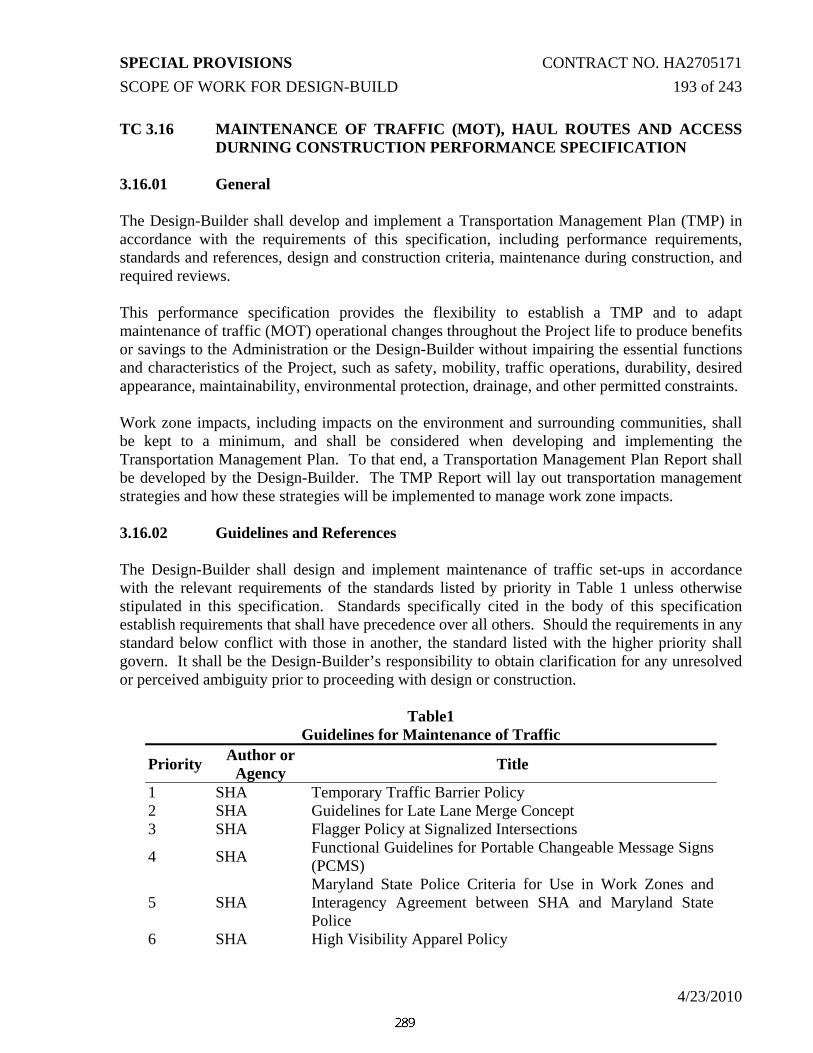
SPECIAL PROVISIONS CONTRACT NO. HA2705171 SCOPE OF WORK FOR DESIGN-BUILD 193 of 243
4/23/2010
TC 3.16 MAINTENANCE OF TRAFFIC (MOT), HAUL ROUTES AND ACCESS DURNING CONSTRUCTION PERFORMANCE SPECIFICATION
3.16.01 General The Design-Builder shall develop and implement a Transportation Management Plan (TMP) in accordance with the requirements of this specification, including performance requirements, standards and references, design and construction criteria, maintenance during construction, and required reviews. This performance specification provides the flexibility to establish a TMP and to adapt maintenance of traffic (MOT) operational changes throughout the Project life to produce benefits or savings to the Administration or the Design-Builder without impairing the essential functions and characteristics of the Project, such as safety, mobility, traffic operations, durability, desired appearance, maintainability, environmental protection, drainage, and other permitted constraints. Work zone impacts, including impacts on the environment and surrounding communities, shall be kept to a minimum, and shall be considered when developing and implementing the Transportation Management Plan. To that end, a Transportation Management Plan Report shall be developed by the Design-Builder. The TMP Report will lay out transportation management strategies and how these strategies will be implemented to manage work zone impacts. 3.16.02 Guidelines and References The Design-Builder shall design and implement maintenance of traffic set-ups in accordance with the relevant requirements of the standards listed by priority in Table 1 unless otherwise stipulated in this specification. Standards specifically cited in the body of this specification establish requirements that shall have precedence over all others. Should the requirements in any standard below conflict with those in another, the standard listed with the higher priority shall govern. It shall be the Design-Builder’s responsibility to obtain clarification for any unresolved or perceived ambiguity prior to proceeding with design or construction.
Table1 Guidelines for Maintenance of Traffic
Priority Author or Agency Title
1 SHA Temporary Traffic Barrier Policy 2 SHA Guidelines for Late Lane Merge Concept 3 SHA Flagger Policy at Signalized Intersections
4 SHA Functional Guidelines for Portable Changeable Message Signs (PCMS)
5 SHA Maryland State Police Criteria for Use in Work Zones and Interagency Agreement between SHA and Maryland State Police
6 SHA High Visibility Apparel Policy

SPECIAL PROVISIONS CONTRACT NO. HA2705171 SCOPE OF WORK FOR DESIGN-BUILD 194 of 243
4/23/2010
Table1 Guidelines for Maintenance of Traffic
Priority Author or Agency Title
7 SHA Work Zone on 65/60 MPH Roadways 8 SHA Work Zone Safety Policy 9 SHA Office of Traffic and Safety Approved Product List for
Temporary Traffic Control Devices and Miscellaneous Items 10 SHA List of Qualified Removable Preformed Pavement Marking
Material for Maintenance of Traffic 11 SHA Maryland State Highway Standard Sign Book
12 SHA Book of Standards for Highway and Incidental Structures for items identified as Standard in Appendix B of Part 3-Design Requirements
13 SHA Standard Specifications for Construction and Materials Section for items identified as Standard in Appendix A of Part 3-Design Requirements
14 SHA Work Zone Safety and Mobility Policy 15 SHA Guidance on Maintenance of Traffic Alternatives Analysis 16 SHA Transportation Management Plan Guidelines 17 SHA Work Zone Lane Closure Analysis Guidelines 18 AASHTO A Policy on Geometric Design of Highways and Streets
19 SHA Maryland Manual on Uniform Traffic Control Devices (MD MUTCD)
20 FHWA Manual on Uniform Traffic Control Devices (MUTCD) 21 SHA Roadway Delineation Policy 22 AASHTO Roadside Design Guide 23 SHA NCHRP Report 350 Implementation Schedule
24 FHWA National Cooperative Highway Research Program (NCHRP) Report 553 Crashworthy Work Zone Traffic Control Devices
25 FHWA National Cooperative Highway Research Program (NCHRP) Report 350 Recommended Procedures for the Safety Performance Evaluation of Highway Features.
26 SHA Work Zone Safety Tool Box 27 ATSSA Quality Standards for Work Zone Traffic Control Devices
28 SHA Accessibility Policy and Guidelines for Pedestrian Facilities Along State Highways
29 ADA Americans with Disabilities Act Accessibility Guidelines

SPECIAL PROVISIONS CONTRACT NO. HA2705171 SCOPE OF WORK FOR DESIGN-BUILD 195 of 243
4/23/2010
3.16.03 Performance Requirements
3.16.03.01 Administration responsibilities
The Administration’s responsibilities include the following activities: A) Maintaining Quality Assurance (QA) of any MOT analysis, work zone
impact management strategies and temporary traffic control plans from the Design-Builder;
B) Liaising with and monitoring the Design-Builder’s performance for compliance with this Contract’s requirements;
C) Maintaining documentation for the TMP as developed by the Design-Builder;
D) Providing a trained individual to implement and monitor the TMP during construction;
E) Monitoring implementation of the TMP to verify that strategies are being implemented on schedule and in the manner planned, and that they are effectively managing the work zone impacts.
3.16.03.02 Design-Builder personnel requirements
This project requires the Design-Builder to have a team experienced in Maintenance of Traffic, including work zone design, work zone traffic analysis, and traffic control devices and setups. Traffic Manager: The Design-Builder shall provide a Traffic Manager (TM) on-site whose sole responsibility is to supervise and continuously monitor the installation and maintenance of all traffic control devices. The TM shall be equivalent to, meet the requirements of, and perform all duties of Section 104.18 of the Administration’s Standard Specifications for Construction and Materials. The Design-Builder shall authorize the TM to direct traffic changes to ensure safe and continuous traffic flow and to direct traffic operations after a traffic incident has occurred. A TM shall be available at all times and be on-site within a ½ hour throughout the duration of the Project. The TM shall document all daily maintenance of the traffic control setup, including but not limited to maximum queue lengths/delays, work zone modifications, incidents, and suggested improvements. Minimum qualifications of the TM include successful completion of the Administration’s Temporary Traffic Control Traffic Managers Training Course and five years experience in work zone traffic control. Flaggers: The Design-Builder shall provide flaggers who have completed an American Traffic Safety Services Association (ATSSA) flagger training course within the last four years and meet the requirements for Section 104.15 of the Administration’s Standard

SPECIAL PROVISIONS CONTRACT NO. HA2705171 SCOPE OF WORK FOR DESIGN-BUILD 196 of 243
4/23/2010
Specification for Construction and Materials. The flaggers provided shall maintain their flagger certification throughout the life of the Project. 3.16.03.03 Maintenance of Traffic – General Requirements
All maintenance of traffic design and implementation shall be performed in accordance with the following performance requirements: A) Provide for the safe and efficient passage of pedestrians (including those with
disabilities), bicycles, and vehicular traffic through and around construction zones;
B) Prohibit use of new permanent pavement construction as haul route(s); C) Minimize negative impacts on residents, commuters, and businesses; D) Provide convenient and logical rerouting of traffic (by using advance warning
systems and directional and informational signing, lighting, and striping) to provide “driver friendly” detours and to maximize the safety of the traveling public;
E) Maintain and provide access at all times to property by owners, customers, visitors, and emergency vehicles;
F) Provide a safe travel corridor while minimizing any unnecessary investment in the existing infrastructure that is being replaced;
G) Develop and coordinate MOT activities with the Maryland State Police, local law enforcement, and other emergency service agencies to ensure public safety and emergency response times are not compromised;
H) Coordinate MOT activities and Traffic Control Plans with other construction projects;
I) Provide Traffic Control Plans (TCPs) for each major phase of construction (see Section 3.16.06 of this performance specification);
J) Provide for a Public Outreach campaign to be implemented in cooperation with the Administration; and
K) Develop an incident management plan for accidents occurring within the Project limits, including accident prevention strategies, emergency procedures, reporting requirements, and mitigation strategies.
3.16.04 Design and Construction Criteria
3.16.04.01 Traffic Through Construction Zones The Design-Builder shall perform the following:
A) Implement Traffic Control Plans for all roadways within the Project limits in a
manner that safely and efficiently accommodates traffic at all times. B) Provide all material, labor, equipment, and personnel to effectively carry out the
TMP. All equipment and tools shall be in good operating condition and shall be kept in proper adjustment throughout the duration of the project. All materials

SPECIAL PROVISIONS CONTRACT NO. HA2705171 SCOPE OF WORK FOR DESIGN-BUILD 197 of 243
4/23/2010
and supplies shall be of good quality and suitable for the assigned work. C) Provide and use all safety equipment, including (but not limited to) hard hats,
safety vests and clothing required by State and Federal regulations and SHA policies and procedures.
D) Begin maintenance of traffic activities at the start of construction work (including preparatory MOT work), or when first hauling construction materials and/or equipment, whichever is earliest and continue MOT activities until Completion of the Project.
E) Arrange and host a pre-traffic switch meeting with the Administration and all affected agencies at least two weeks prior to switching traffic.
F) Identify desired full roadway closures (for any period of time) and present an approval request to the Administration for review and concurrence during the design review process.
G) Correct all traffic control deficiencies immediately upon notification or observance of the deficiency.
H) Design all geometric aspects of temporary roadways for the assigned posted speed.
I) Design all active roadways to accommodate drainage such that there are no puddles or icing on the traveled roadway or shoulders.
J) Ensure appropriate MOT and flagging procedures are employed during all phases of construction, including mobilization activities.
3.16.04.02 Public Information and Outreach
The Design-Builder shall actively assist the Administration in providing advance information to the public regarding construction phasing, detour routes, and expected travel impacts and coordinate these activities through frequent meetings with the Community Outreach Manager. The Design-Builder shall coordinate with the Administration regarding special events that may affect traffic patterns through and around the Project limits and adjust the TMP and TCPs as needed. 3.16.04.03 Public Access The Design-Builder shall maintain access to all businesses, residences, local streets and private driveways at all times, including all temporary approaches and crossings of and intersections with roads and streets. The Design-Builder shall consider any special access needs of property owners and tenants, such as business hours, delivery schedules and circulation patterns. 3.16.04.04 Pedestrian and Bicycle Traffic The Design-Builder shall maintain all existing pedestrian and bicycle access along existing facilities at all times during construction. The pedestrian access way shall be fully compliant with all applicable regulations for accessibility, as defined by the Americans with Disabilities Act (ADA). Whenever an existing pedestrian access route in

SPECIAL PROVISIONS CONTRACT NO. HA2705171 SCOPE OF WORK FOR DESIGN-BUILD 198 of 243
4/23/2010
the public right of way is blocked by a construction, alteration, or maintenance activity, an alternate accessible pedestrian route must be provided. Recreational trails, including bicycle paths, shall also be maintained and kept in good condition. Access to all recreational facilities shall be provided and coordinated with the appropriate governing agency. 3.16.04.05 Schools and Public Transportation Agencies
The Design-Builder shall coordinate with the local schools, appropriate Board of Education, and public transportation agencies for both city and local counties to maintain bus, private vehicle, and pedestrian access to education facilities and public transportation services in the area. Access to bus stops shall also be maintained. Construction impacts on school bus and public transportation routes shall be coordinated with the local agencies. 3.16.04.06 Detour Routes
The Design-Builder shall design, place, and maintain all traffic detours required during construction. Wherever possible, use State routes of a similar caliber (i.e. similar number of travel lanes and similar roadway classification as the road being closed) for detour routes. The Design-Builder is responsible for obtaining all necessary permits from all agencies for temporary roadways, including construction and/or haul routes. Detour routes shall be required when complete road or ramp closures are necessary. Proposed detour routes shall be included in the Traffic Control Plans and reviewed through the design review process (see Section 3.16.06 of this performance specification). Complete closures of roadways will not be permitted without the express written approval of the Administration as part of the design review process prior to closure. Specific identification and written documentation of the proposed closure, including traffic and operational impacts, shall be provided to the Administration during the design review process for each request. Based on the concept plans included in the RFP, it is anticipated that a full ramp closure of Ramp 6 will be required for the reconstruction of Ramp 6. During this ramp closure, it is anticipated that traffic will be detoured along eastbound US 40 onto Ramp 7 via the installation of a temporary traffic signal and temporary intersection on US 40 at Ramp 7. The temporary traffic signal will be a half signal to control eastbound US 40 left turns and westbound US 40 through traffic. The Design-Builder must provide adequate storage lengths approaching the intersection to accommodate estimated queues. Refer to section 3.12 for more details on queuing analysis and the required sight distances and operation of this temporary traffic signal. The Design-Builder shall also provide all necessary advanced signing approaching the temporary traffic signal.

SPECIAL PROVISIONS CONTRACT NO. HA2705171 SCOPE OF WORK FOR DESIGN-BUILD 199 of 243
4/23/2010
The Design-Builder shall close the permanently close the existing median opening along US 40 north of the intersection concurrent with turning on the temporary traffic signal so as to avoid the use of the existing opening to bypass the temporary signal.
3.16.04.07 Motorist Guidance
The Design-Builder shall provide guidance and signage to and along the entire length of every detour route to motorists who are diverted around or traveling through the construction areas. Signing that is not in compliance with the Md MUTCD or Category 1 of the Administration’s Book of Standards shall be corrected within 24 hours, unless the sign is a critical regulatory or warning sign, in which case the sign shall be corrected within 6 hours of notice. If the deficiency is caused by an accident, the 6 hours begins when access to the area is available. For closures of surface streets or changes in roadway configurations, the Design-Builder shall provide guide signs in accordance with the TCP for that particular phase, Md MUTCD and Category 1 of the Administration’s Book of Standards. At least seven (7) Calendar Days before a road closure or major change in the roadway configuration or travel pattern, the Design-Builder shall utilize portable variable message signs warning motorists of the pending changes. Messages to be displayed shall be submitted to the Administration for review and comment. The Design-Builder shall coordinate motorist guidance activities with the Community Outreach Manager. 3.16.04.08 Work Zone Intelligent Transportation Systems (ITS)
The Design-Builder shall utilize existing and future CHART and SHA variable message signs and/or coordination with CHART and SHA to provide messages over the existing highway advisory radio (HAR) system as part of the TMP. It is the responsibility of the Design-Builder to coordinate the operation of these signs and the implementation of the appropriate messages with the Administration. 3.16.04.09 Construction Access and Haul Routes The Design-Builder shall provide all construction roads required for delivery of fill, asphalt, concrete, bridge girders, and all other materials required for the Project. It is the responsibility of the Design-Builder to obtain all necessary permits from all applicable agencies for construction, maintenance, and removal of temporary roadways, including construction and/or haul roads. 3.16.04.10 Local Roadway Crossings
The Administration will allow construction traffic to cross roadways that intersect with the Project as long as the crossing is maintained within the Project ROW. Proper flagging procedures and/or temporary traffic signals are required to facilitate construction traffic crossing local roadways. The Design-Builder shall ensure that delays incurred to

SPECIAL PROVISIONS CONTRACT NO. HA2705171 SCOPE OF WORK FOR DESIGN-BUILD 200 of 243
4/23/2010
local roadways as a result of at-grade crossing operations do not exceed the mobility thresholds established by the Administration’s “Work Zone Lane Closure Analysis Guidelines”. 3.16.04.11 Emergency Response
The Design-Builder shall cooperate with the Maryland State Police, local law enforcement, and other emergency response agencies in their response to accidents, fires, spills, or other emergencies in any area affected by the Project, including those on the construction site and on traffic lanes open to the public. The Design-Builder shall cooperate in all Administration investigations of accidents and other incidents along the Project. The Design-Builder shall work with emergency service providers and address their concerns about emergency access to and in the corridor, which may include installing gates to allow emergency personnel to access the Project area. 3.16.04.12 Field Verification of Traffic Operations
The Design-Builder shall be responsible for monitoring queues and delays during maintenance of traffic operations. If the thresholds established in the Administration’s “Work Zone Lane Closure Analysis Guidelines” are exceeded, the Design-Builder shall modify the maintenance of traffic plans or incorporate other mitigation strategies to reduce the queues and delays below the threshold levels. All proposed changes shall be submitted to the Administration for review. 3.16.04.13 MOT Restrictions
Refer to Special Provision – Section 104.01 – Traffic Control Plan for work restrictions and temporary lane closure and/or shoulder closure requirements. Failure to restore full traffic capacity within the time specified will result in a deduction in Contract Price assessed on the next Periodic Payment. Refer to Special Provision – Section 104.01 – Traffic Control Plan for the assessed MOT deductions.
3.16.04.14 Advance Notification Requirements
The Design-Builder shall submit to the Administration a lane closure permit request form for approval of each lane closure. Lane closures will not be allowed without an approved written closure request.

SPECIAL PROVISIONS CONTRACT NO. HA2705171 SCOPE OF WORK FOR DESIGN-BUILD 201 of 243
4/23/2010
Type of Lane
Closure Minimum
Advanced Notice Maximum Advanced
Notice 1 30 Days 45 Days 2 10 Days 21 Days 3 7 Days 14 Days 4 3 Days 14 Days
Type 1- Planned and acceptable closures of an arterial or local street, traffic switches, new road openings, or changed traffic patterns. Type 2- A lane(s) closure that would have significant impact on traffic, such as temporarily stopping traffic completely (traffic drags), closing 2 or more lanes, or flagging operations. Type 3- A lane closure that would have minor or no impact on the flow of traffic, such as closing one lane on a three-lane roadway during off-peak hours. Type 4- A lane closure that would close a shoulder (right or left). For Type 1 closures, the Design-Builder shall make provisions in the MOT Phase Plan for local traffic to access properties and businesses at all times on the closed arterial or local street. Type 1 and 2 closures will require extensive media and stakeholder notification effort and coordination among various local and State agencies. The Design-Builder shall assist with all notification and coordination efforts All notice exclude weekend and holidays. The lane/shoulder closure request shall be submitted on a Lane/Shoulder Closure Request Form provided by the Administration and shall be submitted electronically. The information provided on the form shall include, but not be limited to, the following:
1) Location: Roadway name or State route number; 2) Project Number; 3) Direction: West/East/North/South; 4) Lane Closure Type: 1, 2, 3 or 4; 5) Duration: Date and times; 6) Limits: Beginning or work zone to end or work zone; 7) Nature of work and justification of lane/shoulder closure; 8) Number of remaining lanes on roadway; 9) Lane(s)/Shoulder(s) to be closed-specifically left, right, middle,
left middle, right middle, shoulder, etc.; 10) Ramp location to be closed;

SPECIAL PROVISIONS CONTRACT NO. HA2705171 SCOPE OF WORK FOR DESIGN-BUILD 202 of 243
4/23/2010
11) Traffic Control Plan sheet number; 12) Appropriate Administration typical application; 13) Point of Contact: Field Inspector; 14) Contact Information; 15) Any detours required; 16) Notes: Any other pertinent information that may be needed to
facilitate in clarifying closures; and 17) State Police request and required number of troopers.
The Design-Builder shall contact and notify the Administration 30 minutes prior to initiating all lane closures and after removing all lane closures. 3.16.04.15 NCHRP Report 350 Implementation Schedule All items for the maintenance of traffic shall be crashworthy in conformance with the Administration’s NCHRP Report 350 Implementation Schedule. When conformance with NCHRP Report 350 is required, the manufacturers’ certifications that the devices comply with the specified criteria shall be reviewed by the Design-Builder and approved in writing, and copies of the certifications and approvals shall be provided to the Administration for consultation and written comment.
All maintenance of traffic (MOT) products used on the Project, including temporary pavement markings, shall be listed on the Administration’s (Office of Traffic and Safety) Qualified Products List (QPL), unless submitted and approved through the Administration’s Maryland Product Evaluation List (MPEL) Program. 3.16.04.16 Work Zone Speed Limits For all construction phases where temporary traffic control devices are provided along US 40, a posted work zone speed limit of 40 mph shall be provided along US 40 in both directions within the Project limits. During the effected construction phases, the Design-Builder shall provide work zone speed limit signs and any additional signing on US 40, as necessary. If the Design-Builder requires a work zone speed limit reduction in any other area throughout the Project limits, the Design-Builder shall submit a request in writing to the Administration for review, comment, and approval. 3.16.04.17 Work Zone Automated Speed Enforcement Work zone automated speed enforcement (ASE) may be implemented in conjunction with this Project if it is determined that the work zone speed limit will not be reduced to a limit less than 45 mph and if the roadway meets the Administration’s requirements for ASE. If work zone ASE is implemented, the Design-Builder shall coordinate the location of the ASE vehicle with the Administration and Maryland State Police (MSP) and provide appropriate advanced warning signing for speed enforcement, as directed by the Administration. In addition, the Design-Builder shall provide two speed display trailers,

SPECIAL PROVISIONS CONTRACT NO. HA2705171 SCOPE OF WORK FOR DESIGN-BUILD 203 of 243
4/23/2010
selected from the Administration’s QPL, in conjunction with ASE on this Project. The Design-Builder shall confirm the appropriate model of the speed display trailers prior to obtaining them from the supplier.
3.16.05 Development and Review of the Transportation Management Plan
The Transportation Management Plan (TMP) shall include Traffic Control Plans (TCP), as well as Transportation Operations (TO) and Public Information and Outreach (PI&O) strategies. The TMP shall: A. Evaluate work zone impacts and develop strategies to mitigate those impacts through the
use of improved transportation operations and management of the transportation system (refer to Section 3.16.05.01 of this Performance Specification). Impacts and strategies shall be documented in a TMP Report.
B. Include traffic control plans that accommodate project and site specific considerations
(refer to Section 3.16.06 of this Performance Specification). C. Include strategies to communicate with the public and concerned stakeholders, before and
during the project, through the development of a public outreach plan.
The Administration has prepared a preliminary TMP for this Project. The preliminary TMP has been included on ProjectWise for reference to the Design-Builder during the TMP development process.
3.16.05.01 Transportation Management Plan Report
The Design-Builder is responsible for developing a temporary traffic control system that best meets the performance requirements and construction activities. Therefore, maintenance of traffic conceptual design shall be done concurrently with a work zone impacts assessment and traffic analysis. This effort shall be documented in a Transportation Management Plan (TMP) report. The Transportation Management Plan report shall be submitted to the Administration for review and comment at the Definitive Design stage. The report shall include discussion of the following and all supporting documentation:
(A) Work zone impacts assessment for the proposed MOT; (B) Traffic analyses for each phase of MOT; (C) Work zone impact management strategies.
3.16.05.02 TMP Report Format
(A) All the pages within the report shall be numbered and dated. (B) The report shall be placed in an 8½ by 11 inch, 3-hole binder that allows

SPECIAL PROVISIONS CONTRACT NO. HA2705171 SCOPE OF WORK FOR DESIGN-BUILD 204 of 243
4/23/2010
for insertion of revisions and removal of old data. (C) The Design-Builder shall make revisions to the report as required to keep
reports current with design and construction activities. The date of the revision shall be placed on all pages. Pages to be added, replaced or removed shall be designated. Revisions shall be 3-hole punched for easy placement in the reports.
(D) The final approved report shall be converted to a Portable Document Format (pdf) file, including all maps and exhibits. The electronic file shall be delivered to the Administration for their records.
(E) Sections for inclusion in the TMP include: 1) Introduction (Cover Page, Table of Contents, etc.) 2) Executive Summary 3) TMP Roles, Responsibilities and Contact Information 4) Project Description, including goals and constraints 5) Existing Conditions 6) Work Zone Impacts Assessment (Refer to Section 3.16.05.03 of
this Performance Specification) 7) Work Zone Traffic Analysis (Refer to Section 3.16.05.04 of this
Performance Specification) 8) Work Zone Impact Management Strategies (Refer to Section
3.16.05.06 of this Performance Specification) 9) Access and Mobility Plan (refer to Section 3.16.05.07 of this
Performance specification) 10) Contingency Plan (Refer to Section 3.16.05.08 of this Performance
Specification) 11) Incident Management Plan (Refer to Section 3.16.05.09 of this
Performance Specification) 12) Public Outreach Proposal (Refer to PS 302 – Public Outreach) 13) Implementation and Monitoring Plan (Refer to Section 3.16.05.10
of this Performance Specification) 14) Supporting Documentation (e.g., Traffic Control Plans)
3.16.05.03 Work Zone Impacts Assessment
Identify how the project’s construction phasing, temporary traffic control zone design, and work zone impact mitigation efforts will impact the project area, how they will affect each other, and how they might adversely impact specific areas, if any. Issues to be considered and discussed in this section of the TMP include:
A) Identification of High-level Construction/Traffic Control Approaches, including proposed construction phasing, traffic control and management, and construction schedule. Discussion may include need for lane closures, total roadway closures, shoulder closures, use of shoulder for travel during construction, use of detour routes and times related to these needs (off-peak, night-work, weekend work, intermittent closures, etc.). High-level

SPECIAL PROVISIONS CONTRACT NO. HA2705171 SCOPE OF WORK FOR DESIGN-BUILD 205 of 243
4/23/2010
maintenance of traffic plans shall be developed that include, but are not limited to, all major traffic shifts, use of temporary roadways, temporary traffic signals, and access modifications to businesses or residences. The duration of each phase shall be noted on the plan. The plans may take the format of 8 ½ x 11, 11x17, or plan-sized (22x34) sheets. These high-level maintenance of traffic plans will be used as a basis for the development of the Traffic Control Plans.
B) Identification of Safety Issues, including pre-existing safety issues and safety implications of proposed construction approach(es). Pre-existing safety issues may include crash history, curve and gradient issues, line of sight issues, weather related safety issues, lack of adequate shoulder width or prevailing speeds. Examples of safety issues from proposed construction approach(es) include implication of night work, lane width issues, lane-closure related safety issues, channelization and work area separation issues, construction staging areas, construction traffic access issues, and management/enforcement of speed in advance of and through the work zone.
C) Identification of Community Impacts and Related Issues, including accessibility issues and other coordination issues. This involves the identification of work zone impacts on the community businesses and residents likely to be affected by the project. Examples include business access relocation, ramp-closure related access issues, detour related mobility impacts, and pedestrian and bicycle related impacts. Other coordination issues may include utility related issues and construction noise issues.
D) Identification of Combined Impacts and Coordination Issues, including identification of nearby and/or concurrent projects and assessment of potential combined impacts of these projects at the corridor/network level.
3.16.05.04 Work Zone Traffic Analysis
Using the Year 2012 No-Build traffic volumes (provided in the preliminary TMP document included in the RFP), the Design-Builder shall analyze all Maintenance of Traffic Phases to ensure that there are no operational or safety issues. Work Zone traffic analysis shall be performed in accordance with methods and tools described in the “Work Zone Lane Closure Analysis Guidelines”. Mobility impacts shall be limited to the allowable mobility thresholds as described in the “Work Zone Lane Closure Analysis Guidelines”. The Administration recognizes that specific work activities and time periods may make it infeasible to comply with the threshold levels contained in the Work Zone Lane Closure Analysis Guidelines. These circumstances shall be outlined in the TMP. For these situations, the Design-Builder shall analyze other MOT Alternatives to reduce the mobility impacts below thresholds. If the MOT Alternatives Analysis does not produce

SPECIAL PROVISIONS CONTRACT NO. HA2705171 SCOPE OF WORK FOR DESIGN-BUILD 206 of 243
4/23/2010
an option that reduces impacts below thresholds, the Design-Builder shall propose additional impact management strategies (transportation operations and/or public information and outreach strategies) to minimize the impact, subject to review and approval by the Administration.
Elements to be included in the traffic analysis portion of the TMP include:
A) Traffic and Travel Characteristics at the Project Location – Include a summary of traffic and travel characteristics in the project area. This may include recurring congestion issues (pre-existing bottlenecks, high-volume areas, etc.) and non-recurring congestion issues (special event traffic issues, weather related delays, potential for incident related traffic congestion, etc), heavy vehicle volumes, directional traffic, and recreational or seasonal traffic issues.
B) Traffic Analysis Strategies – Include a brief description on how the expected traffic conditions during construction were determined. Include source and date of traffic data. Any traffic reduction factors or other parameters assumed for the calculations should be documented.
C) Identify Measures of Effectiveness – List the measure of effectiveness used for the analysis, such as capacity, volume, queue, travel time, diversion rates, safety, adequacy of detour routes, etc.
D) Analysis Tool Selection Methodology and Justification – List the traffic analysis tools used. Include a brief summary on how the tool was selected and criteria used to select the most appropriate tool.
E) Mobility Implications of Construction Approach(es) – Discuss construction approaches that have the potential to impact mobility during the project. This may include lack of shoulders during construction that may require incident management strategies, doing work at night to reduce traffic delays, or traffic capacity and management issues that may exist on a proposed detour route.
F) Analysis Results – Compare existing and construction traffic conditions and operations, with and without work zone impact management strategies (where included). Detour route analysis should be included where detours will be used. Traffic analysis should also address, in a more quantitative manner than the general impacts assessment, the impacts on: 1. Access for residences, businesses, and non-emergency services 2. Access for pedestrians, bicyclists and persons with disabilities 3. Emergency service impacts (fire, ambulance, police, hospitals) 4. Safety 5. Adequacy of detour routes 6. Intersection traffic control (signal timing, signage, etc.) 7. Heavy vehicle traffic (including over-height, over-weight vehicles) 8. Transit operations (bus stops, school buses, other transit
operations) 9. Seasonal impacts (beach traffic, etc.)

SPECIAL PROVISIONS CONTRACT NO. HA2705171 SCOPE OF WORK FOR DESIGN-BUILD 207 of 243
4/23/2010
3.16.05.05 Approved Analysis Techniques and Software
The Design-Builder may utilize the following software packages for analysis of Maintenance of Traffic Plans.
A) For arterial maintenance of traffic operations, the Design-Builder may use Lane Closure Analysis Program (LCAP), QuickZone 2.0, MD QuickZone 2.0, Quewz-98, Highway Capacity Software (HCS), Synchro/SimTraffic, critical lane volume technique, or approved equal (as appropriate) to determine the queuing and level of service impacts caused by the maintenance of traffic plans.
B) For freeway maintenance of traffic operations, the Design-Builder may use LCAP, QuickZone 2.1, MD QuickZone 2.0, Quewz-98, CORSIM, VISSIM, HCS, or approved equal (as appropriate) to determine the queuing and level of service impacts caused by the maintenance of traffic plans.
3.16.05.06 Additional Work Zone Impact Management Strategies
In addition to the impact management strategies and MOT requirements included in this Performance Specification, the Design-Build Team shall list any additional work zone impact management strategies that will be included and discuss anticipated traffic and/or safety impacts of the strategy. The Design-Builder is encouraged to provide additional, cost-effective services to enhance the overall Transportation Management Plan. Additional services should adhere to the standards and be a supplement to the services outlined in this Performance Specification. Any such enhancements may be implemented at any time during the Project and are subject to the Administration’s written acceptance. 3.16.05.07 Access and Mobility Plan
The Design-Builder shall develop an Access and Mobility Plan depicting haul routes and access points. The Access and Mobility Plan shall be reviewed through the design review process with participation by the Administration. Plans shall be presented on paper no smaller than 11” by 17” with appropriate scale. 3.16.05.08 Contingency Plan
The Design-Builder shall develop a contingency plan that specifies actions that will be taken to minimize traffic impacts should unexpected events (unforeseen traffic demand, inclement weather, etc.) occur in the work zone. This plan should also address activities under the Contractor’s control within the work zone. The contingency plan should include, but not be limited to, the following:

SPECIAL PROVISIONS CONTRACT NO. HA2705171 SCOPE OF WORK FOR DESIGN-BUILD 208 of 243
4/23/2010
A) Information that clearly defines trigger points which require lane closure lifting (i.e., inclement weather, length of traffic queue exceed thresholds);
B) Decision tree with clearly defined lines of communication and authority; C) Specific duties of all participants during lane closure operations, such as
coordination with Maryland State Police; D) Standby equipment and availability of personnel for callout.
3.16.05.09 Incident Management Plan
The Design-Builder shall develop an incident management plan for accidents occurring within the Project limits, including accident prevention strategies, emergency procedures, reporting requirements, and mitigation strategies. The incident management plan shall meet the following requirements:
A) The Design-Builder shall provide immediate response to emergencies by trained personnel from an incident response team per the requirement of TC 3.21 – Public Outreach.
B) Immediately following the initiation of actions necessary for the security of people and property, the Design-Builder shall coordinate with the Administration on the investigation of accidents and other incidents.
C) At minimum, the Design-Builder shall provide documentation to the Administration with details on:
1) Cause of disruption (i.e., whether it is construction oriented or
not); 2) Actions being taken to alleviate the problem; 3) Responsible party for the actions; and 4) Anticipated duration of the disruption.
D) The Design-Builder shall establish and manage an emergency response
telephone tree per the requirements of PS 302 – Public Outreach. All appropriate emergency response agencies shall be included on this telephone tree for immediate response in the event of an emergency. The telephone tree shall be divided into areas of expertise so the proper people are called for specific emergency situations.
3.16.05.10 Implementation and Monitoring Plan
The implementation and monitoring plan shall define processes to ensure that the Transportation Management Plan and associated elements, including the Traffic Control Plans and Incident Management Plan, are developed and implemented efficiently and appropriately, and that they are kept up-to-date with necessary modifications during the project.

SPECIAL PROVISIONS CONTRACT NO. HA2705171 SCOPE OF WORK FOR DESIGN-BUILD 209 of 243
4/23/2010
3.16.05.11 Review of and Revisions to TMP Report
The TMP shall be submitted to the Administration for review at the Definitive Design stage. No construction associated with the Design-Build portion of this Project shall occur until the Administration’s comments have been successfully addressed. Any major changes to the TMP Report and associated analysis presented during Definitive Design shall be submitted along with the supporting analysis and documentation to the Administration for review and comment at least 45 days prior to implementing the proposed change. Changes to construction phasing/staging or other impact management strategies that will have a substantial impact on safety or mobility in the project area can be considered major changes. Minor changes (e.g., change to work zone speed limit) shall be submitted to the Administration at least 7 days prior to implementing the proposed change.
3.16.06 Traffic Control Plans
MOT Phase Plans shall be developed for each major phase of construction that requires diversion of traffic. MOT Phase Plans shall be presented on paper no smaller than 22” by 34” with appropriate scale. The Design-Builder shall prepare and present each MOT Phase Plan for review and approval by the Administration. The MOT Phase Plans shall be site specific for each separate portion of Work and shall not simply reference typical drawings, taper tables, or illustrations in various Administration Guidelines or MUTCD. The following components shall be included in each MOT Phase Plan:
A) Description of MOT phase with respect to lane, ramp, or road closures and proposed detour routes;
B) Traffic Analysis/Traffic Modeling for the MOT phase; C) Signal timing plans, if changed; D) Temporary roadways and striping plans; E) Appropriate channelizing devices and barrier locations with spacing and
type of barricades; F) All temporary traffic control devices necessary to safely and efficiently
construct a particular portion of Work; G) Motorist information and guidance; H) Temporary signing, signals, and lighting plans; I) Specific sign messages with sign sizes, spacing or referenced distances,
and Md MUTCD sign designations. The Design-Builder shall provide details for all proposed non-standard Md MUTCD signs;
J) Proposed phased construction of permanent signing; K) Proposed phased construction of traffic signals; L) Pavement marker changes shall be specific and clearly shown on the
Traffic Control Plan with respect to lane widths, pavement marking material, color, location, and widths. Dimensions are necessary to assure proper installation of the pavement markings;

SPECIAL PROVISIONS CONTRACT NO. HA2705171 SCOPE OF WORK FOR DESIGN-BUILD 210 of 243
4/23/2010
M) Flagging locations; and N) Emergency response information.
3.16.06.01 Review of and Revisions to Traffic Control Plans (TCP)
Major changes (e.g., changes in construction phasing or staging) to the approved Traffic Control Plans shall be submitted along with the supporting analysis and documentation to the Administration for review and comment at least 14 days prior to implementing the proposed change. Minor changes (e.g., slight changes in traffic shift location or taper lengths) shall be submitted to the Administration for review and comment at least three (3) days prior to implementing the proposed change. The Administration understands that certain changes to traffic control setups may need to occur in a more timely manner during construction to address urgent safety or mobility problems. These changes should be discussed with the Administration before implementation; however, revisions to the TCP may be documented after their implementation in these circumstances. In these situations, TCP revisions should be documented (either through plan revisions or an approved Field Design Change (FDC)) within 10 days of their implementation. All TCP changes shall be reflected in revisions to the TMP Report when necessary and these revisions shall be made within 21 days of their implementation.

SPECIAL PROVISIONS CONTRACT NO. HA2705171 SCOPE OF WORK FOR DESIGN-BUILD 211 of 243
04/23/2010
TC 3.17 DRAINAGE, STORMWATER MANAGEMENT, AND EROSION & SEDIMENT CONTROL PERFORMANCE SPECIFICATION
3.17.01 GENERAL
The Design-Builder shall provide a Hydrological/Hydraulics Design Engineer who is a Maryland registered Professional Engineer with a minimum of ten (10) years demonstrated experience related to water resources engineering including hydrology and hydraulic investigations, analysis and design of hydraulic structures, including erosion and sediment control. The Hydrological/Hydraulics Design Engineer shall have demonstrated experience with the Maryland Department of the Environment permitting and design requirements. The Administration reserves the right to request a resume to verify said qualifications. As part of the roadway construction to be completed on the US 40 at MD 715 project, the work will include drainage systems, stormwater management, and erosion and sediment control. It will be necessary to assess the adequacy of any existing drainage and stormwater management systems to determine if they will meet future needs, based on the Roadway Performance Specifications and in accordance with SHA’s Drainage Manual. The proposed alignment will include both open and closed section roadway. The proposed drainage system should incorporate ditches, culverts and storm drain systems adequate to meet the project’s needs and convey off-site runoff safely through the site. Ensure that new or rehabilitated facilities cause no adverse impacts upstream and downstream of the project site. The Stormwater Management design and report, drainage design and erosion and sediment control design and report have been approved for construction for Phase 1. The Stormwater Management design and report, drainage design and erosion and sediment control design and report have been conceptually approved for Phase 2. All guidance included in TC 3.17.02 and 3.17.03 pertains to Phase 2.
3.17.02 GUIDELINES AND REFERENCES
3.17.02.01 Guidelines Design and construct the drainage systems, stormwater management, and erosion and sediment control measures according to the relevant requirements of the Guidelines listed by priority in Table 1, unless otherwise stipulated. The Guidelines cited in this specification establish requirements that have precedence over all others. If the requirements in any guideline conflict with those in another; the guideline listed with the higher priority governs. Obtain clarification for any unresolved or perceived ambiguity prior to proceeding with design or construction.

SPECIAL PROVISIONS CONTRACT NO. HA2705171 SCOPE OF WORK FOR DESIGN-BUILD 212 of 243
04/23/2010
Use the most current version of each listed guideline as of the publication date of this RFP.
TABLE 1
GUIDELINES FOR DRAINAGE
Priority Author or Agency Title
1 SHA
Maryland Department of Transportation, publications entitled “Highway Drainage Manual” dated December 1981 or as amended herein and any revisions thereof and “Highway
Drainage Manual Design Guidelines”.
2 MDE Regulation COMAR 26.17.01, “Erosion and Sediment Control”
3 MDE “Erosion and Sedimentation Guidelines for State and Federal Projects”
4 SHA Field Guide for Erosion and Sediment Control
5 MDE “1994 Maryland Standards and Specifications for Soil Erosion and Sediment Control”
6 MDE National Pollutant Discharge Elimination System General Permit for Construction Activity
7 MDE Regulations COMAR 26.17.02 and 26.17.02.01, “Stormwater Management”
8 MDE “Stormwater Management Guidelines for State and Federal Projects”
9 MDE “2000 Maryland Stormwater Design Manual”, Volumes I and II.
(including Chapter 5 – Environmental Site Design, effective 5/2009)
10 MDE Regulations COMAR 26.17.04 “Construction on Nontidal Water and Floodplains.”
11 MDE “Guidelines for Construction on Nontidal Waters and Floodplains.”
12 MDE Regulation COMAR 26.08.02.10, “Water Quality Certification”
13 SHA “Stormwater Management, Erosion and Sediment Control and Waterway Construction Permit Issues and Approaches“
14 NRCS Pond Code MD-378
15 SHA “SHA Stormwater Site Development Criteria - Review Guidelines”
3.17.02.02 References Use the references listed in Table 2 as supplementary materials for the design and construction of the drainage system, stormwater management, and erosion and sediment control measures. These publications have no established order of precedence.

SPECIAL PROVISIONS CONTRACT NO. HA2705171 SCOPE OF WORK FOR DESIGN-BUILD 213 of 243
04/23/2010
TABLE 2
REFERENCES FOR DRAINAGE Author or Agency Title
SHA “Guidelines for Preparing Stormwater Management Concept Reports”, April 2003 draft.
SHA/MDE “Stormwater Quality Management Banking Agreement” dated June 2, 1992, and amended March 1, 1994 and August 2003.
SHA Grass Channel Credit Paper SHA SWM Concept Report
SHA/MDE “Stormwater Management Process Agreements and Interpretations, April 2003”
3.17.03 REQUIREMENTS
3.17.03.01 Surface Drainage Design Design all surface drainage conveyances including but not limited to open channels, inlets, closed storm drainage systems, cross culverts and entrance driveway pipes. Submit the drainage design, in report form as indicated herein, to the Administration for review and concurrence prior to construction.
3.17.03.01.01 Surface Drainage Design - General Requirements Drainage design shall be performed according to the following criteria and regulations:
A. Design and construct the drainage system including the repair and/or replacement of unstable or deteriorating outfalls. Design also includes the regrading of existing outfalls and the replacement of adversely sloped and level (zero gradient) pipes to remove adverse slopes and provide positive drainage.
B. Clean all existing and new pipes and drainage structures to be free of debris and sediment at conclusion of project.
C. Inspect all existing pipes and drainage structures to be used in the Final Design and assess for structural integrity and hydraulic capacity. Compile inspection reports and submit for concurrence. Include photographs and a written report describing the structural integrity of the drainage structure. Repair or replace all existing pipes and drainage structures failing to meet structural integrity or hydraulic requirements.
D. Remove all existing pipes and drainage structures which will not be used in the Final Design or abandon by filling with Flowable Backfill.
E. Provide positive drainage flow in all open and closed systems. Complete

SPECIAL PROVISIONS CONTRACT NO. HA2705171 SCOPE OF WORK FOR DESIGN-BUILD 214 of 243
04/23/2010
designs and obtain Administration approval prior to construction of all temporary and permanent pipe systems.
F. Construct work so as to collect water from any section of the project in an adequate drainage feature. If during design or construction an area of the Project is identified as not having positive drainage in pre-construction conditions, provide adequate measures to ensure positive drainage after construction.
G. Provide adequate connections to maintain all existing drainage systems. Ensure that adequate drainage is provided during interim paving operations (e.g., constructing asphalt berms to divert flow from base course paving to storm drains in closed sections or other precautions as necessary).
H. No adverse impacts to upstream or downstream properties, infrastructure,
or environmental resources are allowed. This may require work to be performed beyond the accepted limits of the roadway improvements, based upon the approved contract limits.
3.17.03.01.02 Surface Drainage Design - Specific Criteria This section contains criteria that are in addition to those contained under Drainage Design General Requirements. Where conflicts arise between these Specific Criteria and those contained in the General Requirements, these Specific Criteria have precedence.
3.17.03.01.02.01 Cross Culverts Refer to Structures Performance Specification, Section 3.11, and Environmental Performance Specification, Section 3.20, for additional cross culvert design requirements.
A. Calculate discharges for appropriate return period storms for cross culverts using USDA, NRCS TR-55 and TR-20 hydrology models unless the drainage area exceeds 200 acres, for which GIS Hydro is added as an acceptable model. Use HEC-RAS for floodplain modeling.
B. Ensure the 100-year headwater pool at new culverts remains within the right-of-way or easements. For existing, replacement, or extended culverts; ensure that the 100-year storm headwater elevation for the proposed conditions is at or below the existing 100-year headwater elevation.

SPECIAL PROVISIONS CONTRACT NO. HA2705171 SCOPE OF WORK FOR DESIGN-BUILD 215 of 243
04/23/2010
3.17.03.01.02.02 Roadway Drainage Design
A. The maximum allowable flow spread in a closed section for a 2-year storm event is 8 ft. and in no case cover more than one half of any travel lane.
B. The maximum allowable flow across entrances is 1 cfs for the 2-year storm event. Maximum flow from the end of curb and gutter is 0.5 cfs for the 2-year storm event.
C. Where practicable, use the roadway inlets and drainage structures in the Administration’s “Book of Standards for Highways and Incidental Structures” or approved equal(s). Submit for approval non-standard structures prior to construction. Within the travel or turning lanes, COG or COS inlets are preferred. If it is necessary to use grated inlets within the travel or turning lanes, place concrete aprons around the inlets unless specifically waived. Where grate inlets are used, bicycle friendly grates such as reticular (WR, WRM, NR, and NRM) or curved vane (CV-S, CV-E) grates are required unless specifically exempted. Ensure that inlets in or immediately adjacent to crosswalks are compliant with the American with Disabilities Act (ADA.)
D. No breaks in curb, such as curb cuts, are allowed for drainage purposes.
E. Design ditches to ensure positive drainage flow. Standing water is not acceptable, except for stormwater management. Design side ditch capacity to convey the 10-year storm with 9-inches of freeboard between the calculated normal flow depth and the edge of pavement.
F. Design ditch linings using HEC-15 "Design of Roadside Channels with Flexible Linings ". Where practicable, the use of Soil Stabilization Matting (SSM) rather than riprap is preferred. Type A matting is temporary matting and is used in ditches where shear stress is less than 1.75 psf or for slope stabilization. Type B matting, permanent matting designed to reinforce the turf stems, is used in ditches where shear stresses are between 1.75 and 3.0 psf. Type C matting is a soil infilled permanent matting used to reinforce the turf root system and is used in conjunction with Type B matting where shear stresses are between 1.75 and 7.0 psf.
G. Design pipe outfalls using HEC-14 "Hydraulic Design of Energy Dissipators for Culverts & Channels". Calculate outlet velocity and at a minimum, provide outfall protection for the same design storm as the culvert. Where conditions indicate that greater outfall velocity may occur at a lesser storm event, provide protection for that event.
i. Riprap outfalls may be used when the outlet Froude number (Fr) is less than or equal to 2.5. Consider stability of the surface at the termination of the apron.

SPECIAL PROVISIONS CONTRACT NO. HA2705171 SCOPE OF WORK FOR DESIGN-BUILD 216 of 243
04/23/2010
ii. Design riprap aprons using Charts in Appendix B to the Culverts section of the Highway Drainage Manual Design Guidelines
1. No. 405.8 “Design of Outlet Protection Minimum Tailwater Condition” is for use where:
o Tailwater is less than ½ the culvert height and the culvert outlets onto flat areas with no defined channel.
o Tailwater is less than ½ the culvert height and the receiving stream is wide enough to accept divergence of the flow.
2. No. 405.9 “Design of Outlet Protection Maximum Tailwater Condition” is for use where:
o Tailwater is greater than ½ the culvert height. o Culvert discharges into a confined channel.
iii. Riprap lined preformed scour holes may also be used when the outlet Fr is less than or equal to 2.5.
H. Concrete lined ditches and concrete slope or channel protection are not allowed unless prior approval is received from the Administration.
I. Refer to Geotechnical Performance Specifications for slope design and construction requirements, and the Environmental Performance Specification for permitted wetland impacts and wetland avoidance.
J. Obtain written approval prior to construction for conversion of existing drainage structures into junction boxes within the roadway. Inspection report data shall be provided for the Administration’s review and written comment.
K. A 100 year service life is required for all added or replaced storm drain pipe under Interstates.
L. Size all added or replaced storm drain so that the 100 year hydraulic grade line remains below the top of all added, replaced, and existing structures located on Interstates.
3.17.03.02 Floodplain and Waterway/Wetland Coordination The Design-Builder is responsible for coordinating analysis of applicable drainage crossings with MDE, FEMA and the Administration. Floodplain crossing requirements can be found in Structures Performance Specifications. Waterway Construction (COMAR 26.17.04) review and approval is required for waterway impacts. Deliver submittals for MDE approval to the Administration for review and coordination with MDE. The Administration has established a review and approval process with MDE for the project. Under that process, the Administration will review and
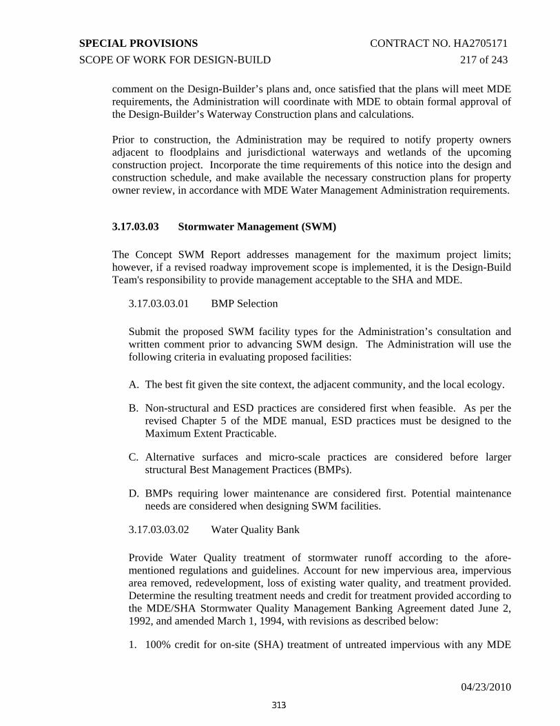
SPECIAL PROVISIONS CONTRACT NO. HA2705171 SCOPE OF WORK FOR DESIGN-BUILD 217 of 243
04/23/2010
comment on the Design-Builder’s plans and, once satisfied that the plans will meet MDE requirements, the Administration will coordinate with MDE to obtain formal approval of the Design-Builder’s Waterway Construction plans and calculations. Prior to construction, the Administration may be required to notify property owners adjacent to floodplains and jurisdictional waterways and wetlands of the upcoming construction project. Incorporate the time requirements of this notice into the design and construction schedule, and make available the necessary construction plans for property owner review, in accordance with MDE Water Management Administration requirements.
3.17.03.03 Stormwater Management (SWM) The Concept SWM Report addresses management for the maximum project limits; however, if a revised roadway improvement scope is implemented, it is the Design-Build Team's responsibility to provide management acceptable to the SHA and MDE.
3.17.03.03.01 BMP Selection
Submit the proposed SWM facility types for the Administration’s consultation and written comment prior to advancing SWM design. The Administration will use the following criteria in evaluating proposed facilities:
A. The best fit given the site context, the adjacent community, and the local ecology.
B. Non-structural and ESD practices are considered first when feasible. As per the revised Chapter 5 of the MDE manual, ESD practices must be designed to the Maximum Extent Practicable.
C. Alternative surfaces and micro-scale practices are considered before larger structural Best Management Practices (BMPs).
D. BMPs requiring lower maintenance are considered first. Potential maintenance needs are considered when designing SWM facilities.
3.17.03.03.02 Water Quality Bank Provide Water Quality treatment of stormwater runoff according to the afore-mentioned regulations and guidelines. Account for new impervious area, impervious area removed, redevelopment, loss of existing water quality, and treatment provided. Determine the resulting treatment needs and credit for treatment provided according to the MDE/SHA Stormwater Quality Management Banking Agreement dated June 2, 1992, and amended March 1, 1994, with revisions as described below:
1. 100% credit for on-site (SHA) treatment of untreated impervious with any MDE

SPECIAL PROVISIONS CONTRACT NO. HA2705171 SCOPE OF WORK FOR DESIGN-BUILD 218 of 243
04/23/2010
approved BMP.
2. Off-site (non-SHA) treatment of untreated impervious areas may be eligible for 80% credit with MDE concurrence.
3. Non-structural BMPs qualify for only Project credit, not bank credit. Excess grass channel credit cannot be applied to the bank.
4. Pavement removal with soil amendments to promote infiltration will be considered as redevelopment and will receive 50% credit. If it is demonstrated that the pavement removal is solely for water quality treatment purposes, then 100% credit will be applied.
5. There will be a 20% surcharge for any debits to the bank.
A conceptual Water Quality Summary Sheet (WQSS) for this project is included in the concept SWM report or otherwise attached to the Contract Documents. The Design Build Team shall not exceed the net debit or reduce the net credit shown on that WQSS. The final WQSS, using the same format, shall be completed by the Design Build Team based on the Final Design. Upon approval and signature by MDE, provide to the Administration’s Highway Hydraulics Division both a photocopy and electronic Excel spreadsheet that includes the XML conversion tool. Accompany those copies with a copy of the MDE SWM/ESC approval letter. Provide all the above each time MDE issues a modification of the approval.
3.17.03.03.03 SWM Specific Engineering Criteria
A. Coordinate details for all the new stormwater management facilities throughout the Project and ensure that they are worked into the concepts for the corridor landscaping. Ensure consistency of facility types, outfall structure designs, detailing, colors, planting palette, landforms, surface area shapes and fencing (if required). Refer to SHA Stormwater Site Development Criteria Review Guidelines for further information regarding landscaping design and SWM.
B. Locate structural BMPs so that the 2-year water surface elevation limit at its closest point is a minimum distance of 15 feet from the edge of pavement.
C. Riser structures and pipe outfall systems are to be designed and constructed according to MD 378. Concrete risers and outfall systems shall be provided. No other riser and pipe systems will be allowed unless specifically approved.
D. Use pressure rated reinforced concrete pipe for stormwater management pond outfalls meeting the requirements of ASTM C-361.
E. Set riser structures into embankments or place so they are easily accessed for maintenance. Riser structures shall also be placed so they are visually

SPECIAL PROVISIONS CONTRACT NO. HA2705171 SCOPE OF WORK FOR DESIGN-BUILD 219 of 243
04/23/2010
unobtrusive. Risers shall be cast in place or precast as one unit. Refer to the 2000 Maryland Stormwater Design Manual for additional SWM specifications.
F. Ensure trash racks on riser openings are adequately protected from corrosion. Hot-dipped galvanized steel, M 111-80 or epoxy coated steel are preferred. Design trash racks that stand away from and completely enclose the riser opening(s). Attach ends of the steel to a frame that attaches to the structure. Use similar detailing for all trash rack designs on the structure and throughout the Project.
G. Use concrete slabs to cap outfall structures whenever possible. When open tops are necessary, place a non-horizontally mounted trash rack at an angle of not flatter than 1” vertical for every 12” horizontal in order to reduce the potential for clogging.
H. Use slotted perforated pipes surrounded by aggregate for low flow and dewatering. Geotextile is not acceptable. Anchor pipes extending into ponds against flotation.
I. SWM embankments with impervious cores and/or cut-off trenches shall be planted with herbaceous plants or turf grass. Do not plant woody material on such embankments, within 15 feet of the toe of pond embankments, or within 25 feet of pond outfall structures. Allowable material for the SWM embankment clay core and cut-off trench conforms to A-2-7, A-7-2, A-4-7, A-7-4, or A-7. Maximum particle size is three inches.
J. Use filter diaphragms for embankment seepage control. Anti-seep collars are not allowed unless specifically approved.
K. Obtain a BMP number for each structural BMP constructed on the Project.
L. Provide adequate access to SWM facilities for maintenance. Ensure each part of the facility is accessible by the equipment needed to maintain or rehabilitate the facility. Underground facilities require that no point within each separate chamber of a facility shall be more than 100 feet from an access point. For example, a 200 foot long chamber with a manhole in center meets this requirement since no point in chamber is more than 100 feet from an access point.
M. The minimum required service life for the structural elements (including pipes) of underground SWM facilities is 50 years. Whenever any of the structural elements are under a roadway, or extend more than 10 feet below the surface, the minimum required service life is 100 years.
3.17.03.04 Erosion and Sediment Control (ESC)

SPECIAL PROVISIONS CONTRACT NO. HA2705171 SCOPE OF WORK FOR DESIGN-BUILD 220 of 243
04/23/2010
Design, obtain approval from MDE and the Administration, and implement an ESC Plan and Sequence of Construction. Obtain all approvals prior to commencing earth disturbing activities.
3.17.03.04.01 Severe Weather Event
Maintain erosion and sediment controls at all times. A severe weather event for erosion and sediment control purposes is defined as at least 3.0 inches of rainfall in a 24 hour period. The Design-builder shall Maintain, repair, or replace any damaged devices within 48 hours of a severe weather event. A severe weather event shall be determined by rainfall data obtained from the nearest official National Weather Service gauge station to the project.
A lump sum payment of $28,264 will be paid for each Severe Weather Event that occurs between the start of grading operations and removal of all erosion and sediment controls for which the Contractor is eligible. The payment will be full compensation for the maintenance, repair and/or replacement of any and all erosion and sediment control devices damaged by the severe weather event and for all material, labor, equipment, tools, and incidentals necessary to complete the work. The payment for each severe weather event will only be made if a minimum rating of “B” immediately before and within 48 hours following the severe weather events is maintained and upon receipt of official weather records documenting the occurrence of the severe weather events.
3.17.03.04.02 ESC Specific Design Criteria
Ensure that Erosion and Sediment Control Designers have successfully completed the Administration’s “Designers Erosion and Sediment Control Training” Clearly delineate the Limit of Disturbance (LOD) on the ESC Plans by including a table of the break points with Station and Offset. Prior to permanent seeding and mulching, cover slopes outside the roadway hinge point, flatter than and including 2:1 slopes, with 2 inches of topsoil. Cover slopes within the roadway hinge points, flatter than and including 2:1 slopes, with 4 inches of topsoil.
Evaluate slopes steeper than 2:1 for slope stability and prepare to promote vegetative growth according to Geotechnical Performance Specification and Planting and Landscape Architectural Performance Specification.
Ensure daily stabilization for land disturbance within any drainage areas adjacent to wetlands and streams in the design and implementation of the ESC plans.

SPECIAL PROVISIONS CONTRACT NO. HA2705171 SCOPE OF WORK FOR DESIGN-BUILD 221 of 243
04/23/2010
Potential strategies to limit the potential for erosion may include, but are not limited to, the following:
• Use clear water diversions to the maximum extent feasible to limit the amount of area required to be controlled;
• Stage the construction to limit clearing, grubbing and area of disturbance to what is necessary to carry on a grading operation (EDA) to minimize the area and duration of soil exposure;
• Provide top of fill berms with pipe slope drains to convey discharge down steep slopes,
• Bench long cut or fill slopes to limit the risk of rilling on steep slopes and to lessen the slope of longitudinal ditches; and
• Other innovative techniques presented by the Design-Builder with prior written concurrence from the Administration and approval from MDE prior to construction.
Make every attempt to retain sediment generated by construction operations within the site. Some examples of these may include, but are not limited to, the following:
Stone check dams, compost socks, linings, strip sod, or other erosion inhibitors in influent ditches to sediment traps;
Ensure effective drawdown and dewatering of sediment traps and basins prior to forecast rain events by pumping to filter bag(s) and mulch berm(s) or other approved devices to ensure that dewatered storage component of sediment trap is available for the future storm event(s);
Minimize the potential for re-suspension of particulates; and
Other innovative techniques presented by the Design-Builder with concurrence from the Administration and approval from MDE prior to construction.

SPECIAL PROVISIONS CONTRACT NO. HA2705171 SCOPE OF WORK FOR DESIGN-BUILD 222 of 243
4/23/2010
TC 3.18 NOISE ABATEMENT PERFORMANCE SPECIFICATIONS
No Noise Walls are anticipated on this project.

SPECIAL PROVISIONS CONTRACT NO. HA2705171 SCOPE OF WORK FOR DESIGN-BUILD 223 of 243
4/23/2010
TC 3.19 CONSTRUCTION REQUIREMENTS
3.19.01 Construction Standards
3.19.01.1 Book of Standards
Details and dimensions of drainage structures, TCPs, traffic barriers, etc., shall comply with the Administration's "Book of Standards, Highway and Incidental Structures."
3.19.01.2 Specifications for Construction and Materials
Shall comply with the Maryland Department of Transportation, State Highway Administration Standard Specifications for Construction and Materials, January 2001,including all Special Provision Inserts and these Special Provisions.
3.19.01.3 Industry Standards
Industry standards, such as ASTM and AASHTO, that are referenced in the Administration's or Utility and utility owners' specifications and standards shall also be met. If an item of work is not covered by the Administration's specifications and standards, the materials and construction methods used shall meet the appropriate, nationally accepted industry standards and be submitted to the Administration for approval.
3.19.01.4 Utility Details
All Utility work shall be done in accordance with the latest edition of the utility owners’ details and specifications.
3.19.02 Construction Stakeout
The Design-Build Team shall refer to SP 107 - CONSTRUCTION STAKEOUT (For Design-Build Projects) for project specific requirements.
The Design-Build Team shall engage a Registered Professional Land Surveyor, licensed in the State of Maryland, to determine all lines and elevations for various parts of the Work, as the work progresses:
a. Verify that the field locations of the established horizontal controls and benchmarks correspond with figures shown on the Design-Build Team’s Contract Drawings.
b. Establish vertical references and axis lines showing elevations and other lines and

SPECIAL PROVISIONS CONTRACT NO. HA2705171 SCOPE OF WORK FOR DESIGN-BUILD 224 of 243
4/23/2010
dimensional reference points as required for the execution of the work.
c. Field check facilities and surveys thereof as required by the technical sections of the Specifications.
d. Stake out the limit of disturbance at all wetland areas and tree protection fencing at all Tree Preservation Areas.
e. Stakeout the Right-of-Way Line
3.19.03 Maintenance of Traffic
All maintenance of traffic work is to comply with the approved traffic control plans, the Manual on Uniform Traffic Control Devices (MUTCD), the Maryland Supplement to the MUTCD and special provisions. The Design-Build Team shall maintain vehicle, bike and pedestrian traffic at all times.
a. Advanced Notice Requirements
The Design-Build Team shall notify the Administration's Engineer in advance of implementing any changes in traffic patterns as per requirements of the Maintenance of Traffic Performance Specification.
b. Schedules/Sequences of Construction
The Design-Build Team shall schedule tie-in operations so as not to be working intermittently throughout the area. Schedule and pursue excavation and other construction activities to permit making the connection without unnecessary delays. Perform utility work in conformance with the maintenance of traffic requirements shown on the approved Drawings and/or as indicated in the Standards.
c. Protection of Open Excavation
Pursuant to the General Provisions, the Design-Build Team is responsible for protection of the work and safety of the public.
The use of decking or plates to close trenches, temporary wedge material to prevent pavement edge drop-off, and the installation of temporary channelizing devices and/or traffic barriers may be required as unforeseen conditions develop during construction operations.
3.19.04 Erosion and Sediment Control
Except as noted below, all work shall be done in accordance with the erosion and sediment control (E&S) plans to be prepared by the Design-Build Team and approved by the Maryland Department of the Environment.
a. Plan Adjustments and Revisions

SPECIAL PROVISIONS CONTRACT NO. HA2705171 SCOPE OF WORK FOR DESIGN-BUILD 225 of 243
4/23/2010
If approved by the MDE Sediment Control Inspector, minor field adjustments of the sediment control facilities may be made as required to accomplish the intended purpose.
Major revisions to the approved sediment control plan, as determined by the MDE Sediment Control Inspector, require the review and approval of the State of Maryland Department of the Environment. The Design-Build Team must provide for such review and obtain approval at no additional cost to the Administration.
Any changes to the approved sequence of construction shall be submitted for approval to MDE, Plan Approval Division, and the Administration, Highway Hydraulics Division.
When directed by the Administration’s Engineer, the contractor shall be responsible to implement additional erosion and sediment control measures and modifications to the approved erosion and sediment control plan as required by the MDE Sediment Control Inspector and the Administration’s Environmental Monitor to address unforeseen site conditions and errors and omissions during design at no additional cost to the Administration.
Comply with all Federal, State and local laws, ordinances and regulations pertaining to environmental protection.
b. Protection of Existing Waterways and Highways
Do not dump debris or rubbish of any kind or allow it to fall into a river or on highways. This includes paint splatters and spillage during painting operations. Take care to prevent damage and injury to personnel, vessels, and vehicles using rivers, highways, or pedestrian ways. Provide devices and maintain as required to prevent such occurrences. Promptly remove any material or items falling in a river, on adjacent banks, or on highways and immediately report to the Engineer and the jurisdictional agency.
c. Fish and Wildlife Resources
Do not alter water flows or otherwise disturb native habitat near or adjacent to the project construction area, unless otherwise stipulated in the project’s permits and approved as an authorized action by the appropriate regulatory agencies.
d. Staging Areas
Do not use, in connection with this Contract, for storage, as a staging area, or as a preparation site any cultural resource facility, building, site or cleared area that is, as of the date of this Contract, on or eligible for listing on the National Register of Historic Places (16 U.S.C., paragraph 470a) without prior approval of the Engineer.
For the purpose of the preceding paragraph, the term "cultural resource" includes districts, sites, buildings, structures, and objects significant in American history, architecture, archaeology, or culture.

SPECIAL PROVISIONS CONTRACT NO. HA2705171 SCOPE OF WORK FOR DESIGN-BUILD 226 of 243
4/23/2010
3.19.05 Topsoil, Turf Establishment, and Sodding
Topsoil shall be placed according to 3.17.03.09, E&S Specific Criteria.
Seeding shall be performed as per Section 705. The amount of limestone and starter fertilizer for SALVAGED topsoiled areas shall be found in the Nutrient Management Plan Special Provisions of this IFB OR WILL BE DEVELOPED PRIOR TO PERMANENT SEEDING AND SODDING. The Design-Build Team shall provide a minimum of 95 percent stand (coverage) of turf meeting 705 specifications for flat and slope areas. For slope areas 3:1 and steeper tracked with a bulldozer, the stand (coverage) of turf shall be a minimum of 50 percent.
Sodding shall be performed as per Section 708. Two inches of topsoil shall be placed UNDER the sod. The Design-Build Team shall provide a minimum of 99 percent stand (coverage) of turf with adequate soil moisture meeting Section 708 specifications.
TURF STANDS AND SODDING SHALL BE EVALUATED BY DIVIDING THE PROJECT INTO 10 EVENLY SPACED CROSS SECTIONS. EVALUATIONS SHALL BE CONDUCTED ALONG EACH CROSS SECTION, EVERY 25 SQUARE FEET.
The turf from seeding and sodding shall have a dark green color. Both the seeding and sodding requirements shall be met at the time of the semi-final and final inspections, as approved by the the Design-Build Team and a representative of the Landscape Operations Division.
Mowing shall be performed as per the Administration’s INTEGRATED VEGETATION MANAGEMENT MANUAL FOR MARYLAND HIGHWAYS. Mowing shall be evaluated at the beginning of each month during the growing season.
3.19.06 Landscape and Reforestation Plantings
All materials shall conform to Section 920 of the Maryland Department of Transportation, State Highway Administration, Standard Specifications for Construction and Materials, January 2001.
All construction shall conform to Sections 701 through 715, inclusive, of the Maryland Department of Transportation, State Highway Administration, Standard Specifications for Construction and Materials, January 2008.
3.19.07 Protection of Existing Utilities
Attention of the Design-Build Team is directed to the presence of utility lines of various types in the existing and proposed streets or highways in which the construction project is to be performed. The Design-Build Team shall exercise special care and extreme caution to protect and avoid damage to utility company facilities as described in this RFP/IFP. The Design-Build Team shall take into consideration the adjustments and installations by public utilities in areas within the limits of this contract. Existing utilities are located and shown in the utility designation file as they are believed to exist; however, the Administration assumes no responsibility for the accuracy of these locations. The Design-Build Team shall be responsible for determining the location of all existing utilities and incorporating them into the design prior

SPECIAL PROVISIONS CONTRACT NO. HA2705171 SCOPE OF WORK FOR DESIGN-BUILD 227 of 243
4/23/2010
to initiating construction.
The Design-Build Team shall locate all existing utilities and be responsible for their safety and continuous service. Should any existing utilities be damaged or destroyed due to the operations of the Design-Build Team, the damaged or destroyed components shall be immediately replaced or repaired as necessary to restore the utility to a satisfactory operating condition. These repairs or replacements shall be at no additional expense to the Administration or the owner of the utility.
The Design-Build Team shall inform the respective utility companies at least fourteen days prior to working in any area. In addition, the Design-Build Team shall give sufficient notice to the specific utilities of the Design-Build Team’s overall plan for construction and utility relocations. The utility companies will establish the lead time necessary to meet the applicable utility work schedule and coordinate with the Design-Build Team’s work operations based upon the Design-Build Team’s overall plan.
For a list of the known utility owners have existing facilities within the limits of this contract see Section 875 – Utility Statement, location elsewhere within this RFP/IFB:
All notifications to the above utility companies and "MISS UTILITY", 1.800.257.7777, shall be given 48 hours (two full working days) in advance of working in the area of the specific affected utility. The notification to "MISS UTILITY" is required whenever any excavating or similar work is to be performed.
The Design-Build Team shall be responsible for all frame and cover adjustments required by the project, either making the adjustment, or reimbursing the utility owner. The Design-Build Team shall provide for access to all utility manholes, valves, vaults, poles, and all other above ground utility equipment, both during and after construction. This access shall consist of a firm, ten foot minimum width, route to the equipment, drivable for an AASHTO SU 30 truck. This access shall also consist of a ten foot minimum width by twenty foot minimum length parking area immediately adjacent to the equipment. Both the route and the parking area shall be completely with in State right-of-way, shall have a four percent maximum cross slope, and shall have an eight percent maximum longitudinal slope. Shoulders may be part of these routes and parking areas, but travel lanes shall not be. The Design-Build Team shall design and construct this access so utility company personal and vehicles can safely get to the equipment from public roads, work at the equipment, and safely return to the public road.
If an adjustment is required to facilities, it is necessary that the existing facilities remain in service until the new construction is complete and placed in service. Also, when adjustments are required, establishment of lead times is necessary to meet the applicable utility schedule and coordination with the Design-Build Team’s work operation.
Working around or protecting the utilities, removal and disposal of materials from the utilities and cooperation with the owners of the utilities and with other contractors will not be measured but the cost will be included in the Contract Lump Sum price bid.

SPECIAL PROVISIONS CONTRACT NO. HA2705171 SCOPE OF WORK FOR DESIGN-BUILD 228 of 243
04/23/2010
TC 3.20 ENVIRONMENTAL PERFORMANCE SPECIFICATION
3.20.01 General
The Design-Builder shall conduct its design and construction activities in accordance with these specifications such that no action or inaction on the part of the Design-Builder shall result in non-compliance with the requirements of the necessary permits and approvals required by the Project.
3.20.01.01 General Environmental Philosophy
The US 40/MD 715 Project passes through an area of diverse environmental, community, and cultural resources. Protection of these resources is of paramount importance. The philosophy followed by the Maryland State Highway Administration (Administration) during the development of the Concept Plans was to incorporate environmental stewardship measures and avoid and minimize impacts to the natural and forest areas, community, cultural resources (Section 106 Resources), and Parkland (Section 4(f)) to the greatest extent feasible and practical. The Design-Builder shall continue this environmentally sensitive approach and philosophy during the preparation of final design plans and through Project implementation. The Administration has implemented innovative approaches to reward the Design-Builder for high quality environmental performance, as stated in various sections of this Performance Specification. These innovative approaches include incentives for reductions to forest impacts and incentives for reductions to wetland/waterway impacts. The US Army Corps of Engineers and the Maryland Department of the Environment have reviewed the US 40/MD 715 project and have found the wetland and waterway impacts to be acceptable and permittable. Based on input from these agencies as well as the Administration’s environmental stewardship philosophy to avoid, minimize, and mitigate adverse environmental impacts, the Administration has determined that replacing existing, deteriorated stream channel, which is located adjacent to the US 40 Eastbound roadway, between Cranberry Run and a point approximately 800 feet to the east, with a stream having natural channel features is the appropriate approach to relocating the stream.
3.20.02 Guidelines and References
The Design-Builder shall design and implement Environmental requirements in accordance with the relevant requirements of the Guidelines listed by priority in Table 1 unless otherwise stipulated in this specification. Guidelines specifically cited in the body of this specification establish requirements that shall have precedence over all others. Should the requirements in any Guideline below conflict with those in another, the Guideline listed with the higher priority shall govern. It is the Design-Builder’s responsibility to obtain clarification for any unresolved or perceived ambiguity prior to proceeding with design or construction.

SPECIAL PROVISIONS CONTRACT NO. HA2705171 SCOPE OF WORK FOR DESIGN-BUILD 229 of 243
04/23/2010
Appropriate professional standards and regulations shall be utilized for design and construction implementation of all commitments, considerations, permit conditions and approval requirements. Guidelines shall include, but are not limited to the following:
TABLE 1 GUIDELINES FOR ENVIRONMENTAL
Priority Author or Agency
Title
1 Section 106 of the National Historical Preservation Act (16 USC § 470f)
2 Section 4(f) of the US Department of Transportation Act (23 USC § 138)
3 Code of Federal Regulations (CFR) 4 Code of Maryland Regulations (COMAR) 5 MDE / USACE Joint Federal / State MDSPGP-3 Permit
Application and Authorization (Note – Authorization may not be available at that point)
6 Secretary of the Interior’s Standards and Guidelines for Archeology and Historic Preservation (1983 and successors)
7 Standards and Guidelines for Archeological Investigations in Maryland (Shaffer and Cole 1994)
8 Standards and Guidelines for Architectural and Historical Investigations in Maryland (Maryland Historical Trust, 2000)
9 Recommended Approach for Consultation on Recovery of Significant Information from Archeological
Sites, ACFIP 1999 (64 FR 27085-27087) 10 Secretary of the Interior’s Standards for the
Treatment of Historic Properties (36 CFR Past 68) 11 SHA Standard Specifications for Construction and Materials 12 SHA Book of Standards for Highways and Incidental Structures 13 MDE Maryland’s Guidelines for Waterway Construction 14 Rosgen Applied River Morphology
3.20.03 Owner’s Environmental Roles and Responsibilities The Administration has conducted extensive coordination with various environmental and regulatory agencies and the public. At this time, an Independent Environmental Monitor (IEM) is not required by the Administration or by permit condition. However, if there are any changes to the design and/or construction activities that would affect permit conditions or require a modification approval from the regulatory agencies, an IEM may be required by the Administration. In that case, the Administration will provide an IEM, on behalf of the USACE and MDE, who will work with the Design-Builder to confirm that the Design-Builder’s plans and construction methods are in compliance and that all regulatory permit conditions and commitments are met. The Independent Environmental Monitor will:

SPECIAL PROVISIONS CONTRACT NO. HA2705171 SCOPE OF WORK FOR DESIGN-BUILD 230 of 243
04/23/2010
A. Review plans as they are developed;
B. Review the Design-Builder’s environmental compliance implementation;
C. Notify the Design-Builder’s of deficiencies in the compliance with the commitments, considerations, permits and approvals; and
D. Coordinate and attend any meetings involving resource or regulatory agencies.
3.20.04 Design-Builder’s Responsibilities The Design-Builder shall be responsible for compliance with the permit conditions throughout the design and construction of the Project. The Design-Builder shall demonstrate compliance by producing a Compliance Report each quarter, which tracks and confirms compliance with each commitment pertaining to the construction of the Project, and also tracks impacts to wetlands and Waters of the US. The checklist and memorandum shall be submitted to the Administration within one week after the end of each quarter.
3.20.05 Permits and Approvals The Administration will be relying on the Design-Builder to achieve and maintain commitments and permits through a strong Environmental Compliance Plan and partnering with the Administration. The Design-Builder is encouraged to consider environmental stewardship measures that exceed those in the standards and permits, while considering reasonable cost and practicality.
A. As part of this RFP/IFB, the Administration is providing the following permits and approvals based on the proposed activities:
1) Joint Federal/State Wetland and Waterways Permit and Water Quality Certification (WQC)
2) Maryland Department of Natural Resources Reforestation Permit
3) Erosion and Sediment Control Approval (from MDE) - Phase 1 4) Stormwater Management Permit (from MDE) - Phase 1
5) NPDES Construction Activity Permit (MDE)
B. The Design-Builder shall obtain the following permits and/or approvals:
1) Erosion and Sediment Control Approval (from MDE) - Phase 2
2) Stormwater Management Permit (from MDE) - Phase 2
3) All other approvals, permits and licenses, pay all charges, fees and taxes and give notices necessary or appropriate for the implementation of the Project

SPECIAL PROVISIONS CONTRACT NO. HA2705171 SCOPE OF WORK FOR DESIGN-BUILD 231 of 243
04/23/2010
beyond those obtained by the Administration. This includes but is not limited to approvals for on or off-site staging, stockpiling areas, disposal sites and borrows pits.
3.20.06 Permit Modifications and Approvals The Design-Builder shall obtain approvals from the Administration for any changes in design and/or construction activities that affect any permit conditions and would require a modification approval from the regulatory agencies. All conditions in the permits shall be adhered to unless modifications are accepted and approved by the Administration and the regulatory agencies. Delays due to permit modification approval for permits listed in TC Section-3.20.05A, requested by the Design-Builder, will not result in additional costs to the Administration nor will the Contract be extended. The Design-Builder shall not alter the design in such a manner that increases or creates new impacts to forest, cultural resources, parkland, wetland, wetland buffer, waterway, or floodplain compared to those impacts which were authorized by the permits, illustrated in the Concept Plans and defined in the Joint Permit Application impact plates and tables. If the Design-Builder determines that changes to impacts are to be considered through design and/or construction, the Design-Builder shall be responsible for providing to obtain the permits, approvals or modifications from the regulatory agencies. Request for modification to the permits listed shall be accompanied by documentation provided by the Design-Builder to demonstrate that there is no practical alternative. Additional mitigation required with approval of modifications shall be the responsibility of the Design-Builder.
3.20.07 Natural Resources
3.20.07.01 Groundwater The Design-Builder shall be responsible for design measures that maintain and discharge natural groundwater flows and seeps associated with waters of the US and wetlands. The Design-Builder shall provide protective measures at cut slopes, ditching and other activities adjacent to non impacted or temporarily impacted wetlands to ensure that the source of hydrology to that wetland is preserved. If it is determined that the wetland has been altered hydrologically, it will be considered an additional impact, for which the Design-Builder shall be responsible for providing permit modification documentation as well as mitigation at the designated ratios, per COMAR, for the impacts. Within one year of the completion of the construction, an inspection will be conducted by the Administration and the regulatory agencies to determine whether any remnant wetlands have lost their hydrology. If it is determined that remnant wetlands are no longer functioning as a jurisdictional wetland, the Design-Builder shall be responsible for

SPECIAL PROVISIONS CONTRACT NO. HA2705171 SCOPE OF WORK FOR DESIGN-BUILD 232 of 243
04/23/2010
costs associated with the additional mitigation required. Mitigation ratios for the lost wetlands shall be in accordance with COMAR.
3.20.07.02 Surface Water For details on Erosion and Sediment Control and Stormwater Management, see the Drainage, Stormwater Management, and Erosion & Sediment Control Performance Specification. The Design-Builder shall not discharge or allow the release of any sediment laden construction water unless properly treated. The Design-Builder shall obtain Administration approval of all dewatering operations prior to pumping and discharge. Water to be pumped and discharged shall be in conformance with the COMAR Standards. To minimize potential for untreated discharge, the Design-Builder shall designate, design and construct, utilize, maintain and upon conclusion of operations, properly close concrete wash-out pits for all concrete production, transport and placement operations. The location of concrete wash-out pits shall be approved by the Administration prior to use. The pits shall be managed such that no concrete waste or wash water is discharged into waters of the US. This may include the implementation of drying beds with proper sediment controls and treatment of excess wash water on-site or proper off-site disposal. If construction discharges exceed water quality standards identified in COMAR, the Design-Builder shall immediately notify the Administration and resolve any Project related deficiencies within 24 hours. The Administration will request spot-check downloads at any time to verify compliance.
3.20.07.03 Aquatic Biota The Design-Builder shall:
A. Conduct all work so as to avoid/minimize fish mortality from both construction related water quality impairment and in-stream activities. The Design-Builder shall notify the Administration 48 hours prior to the commencement of any stream dewatering or other in-stream activities.
B. Comply with all water quality standards stated in the COMAR for the protection of aquatic biota.
C. Conduct all in-stream work in compliance with the Maryland mandated stream closure period for the Use I stream (March 1 through June 15, inclusive in any year). Any riprap placed shall be constructed so as not to obstruct the movement of aquatic species, unless the purpose of the activity is to temporarily impound

SPECIAL PROVISIONS CONTRACT NO. HA2705171 SCOPE OF WORK FOR DESIGN-BUILD 233 of 243
04/23/2010
water.
3.20.07.04 Wetlands and Waters of the US Direct impacts to wetlands and waterways are anticipated to occur under the Project. The impact plates and table in the Joint Permit Application present the total impacts permitted for the US 40/MD 715 Project. All wetlands and waterways were identified, delineated and surveyed within the Project. Surveyed boundaries of waterways and wetlands are depicted on the Concept Plans. Prior to performing any work on the Project, the Design-Builder shall be responsible for installing temporary orange safety fence and prohibitive signage in English and Spanish adjacent to non-impacted areas of wetlands and their buffers, identified in the Joint Federal/State MDSPGP-3 Permit, along the limits of disturbance and/or right of way. The orange safety fence shall be installed at a maximum of 25 feet from the proposed toe of cut/fill adjacent to wetlands as depicted on the Concept Plans. The wetland (orange safety) fencing locations should be staked prior to the pre-construction meeting. All personnel of the Design-Builder or subcontractors shall be alerted to these designated protection areas.
3.20.07.04.01 Occupying Wetlands/Waterways and Best Management Practices for Work in Nontidal Wetlands, Wetland Buffers, Waterways, and 100-Year Floodplains
See Contract Provisions CP – Occupying Wetlands.
3.20.07.04.02 Avoidance and Minimization The Administration proposed avoidance and minimization techniques during the planning and preliminary engineering phase which consisted of relocated stormwater management facilities and reductions in overall roadway section widths where safety considerations allow. The Design-Builder shall focus its efforts to continue to minimize impacts to wetlands, waterways, floodplains, in all areas of the Project, especially sensitive areas. Engineering designs shall continue to emphasize avoidance and minimization of impacts as the feasibility and effectiveness of using measures such as retaining walls, steeper fill slopes, increased headwall heights, reduced roadway sections and any other feasible minimization efforts are evaluated. Side slopes shall be 2:1 or steeper wherever the fill material is adjacent to wetlands or waterways. Additional avoidance and minimization efforts such as retaining walls, MSE walls, and Reinforced Earth Slopes are encouraged, especially at wetlands. Refer to the Geotechnical Performance Specification.
3.20.07.04.03 Wetland and/or Waterway Impact Reduction Incentive The Design-Build Team is advised upon final acceptance of the constructed project,

SPECIAL PROVISIONS CONTRACT NO. HA2705171 SCOPE OF WORK FOR DESIGN-BUILD 234 of 243
04/23/2010
completion of as-built plans and approval of permit modification by USACE/MDE, the contractor will be reimbursed for any permanent wetland or waterway impact reduction in increments of 0.10 acre. The reimbursement only pertains to reduced permanent impacts within the Limit of Disturbance. This determination will be made by comparing the permanent impacts determined in the as-built plans against the permanent impacts permitted by USACE/MDE in the initial Joint Federal / State MDSPGP-3 Permit. This incentive will be paid at $8000.00 per 0.10 acre saved. 3.20.07.04.04 Stream Relocation The existing, deteriorated stream channel, which is located adjacent to the US 40 Eastbound roadway, between Cranberry Run and a point approximately 800 feet to the east, will be impacted by the proposed and future widening of US 40. The existing stream will be relocated to the south, within the new easements and right-of-way. The stream shall be designed in accordance with SHA’s concept plan. The stream relocation is to be designed in accordance with natural channel design and soil bioengineering concepts and principles. To minimize right-of way-requirements, a stream with only minor meandering is to be designed and constructed. A step pool stream shall be designed and constructed in accordance with MDE’s Guidelines for Waterway Construction, The designer shall provide a basis for the design, including the size and shape of the pools, the width and depth of the step pools, the spacing between step pools, the rock size to be used for the step pools, the profile of the stream, and the hydraulic drop between step pools. The design and construction of the stream relocation shall include the installation of pipe culverts that will accommodate the future construction, by others, of a Commercial Monumental Entrance in accordance with the Administration’s State Highway Access Manual. The center of the future entrance shall be aligned with the center of the existing US 40 median crossing. Stream Specialist: A stream specialist shall be designated by the Design-Builder, with a minimum of ten (10) years of practical stream restoration design and construction experience. The stream specialist should have experience in stream geomorphology, natural channel design, Rosgen Stream Classification Systems, stream diversions and relocations, design and construction of in-stream rock structures, including step-pool systems, proficiency in working with survey data and instruments, grading operations, grade controls and planting operations. The stream specialist shall have stream restoration experience in Maryland and must be familiar with Maryland streams, soils and plants. The stream specialist does not need to be a professional engineer, but shall be a member of a design team that includes a professional engineer and a landscape architect. The administration reserves the right to request a resume to verify said qualifications. The stream relocation design shall be approved by the Administration, the US Army Corps of Engineers, and MDE prior to implementation.

SPECIAL PROVISIONS CONTRACT NO. HA2705171 SCOPE OF WORK FOR DESIGN-BUILD 235 of 243
04/23/2010
3.20.07.05 Reforestation Reforestation work shall include the performance of all required and applicable Maryland Roadside Tree Law, Reforestation Law and Maryland Forest Conservation Act work associated with the Project.
3.20.07.05.01 Forest Avoidance and Minimization
Direct impacts to forest are anticipated to occur under the Project. Surveyed boundaries of forests are depicted on the Concept Plans. Prior to performing any Work, the Design-Builder shall be responsible for performing all tree preservation measures in accordance with Section 120-Tree Preservation of the Standard Specifications for Construction and Materials.
Specimen trees (trees greater that 30” diameter at breast height measured 4.5’ above the ground) were identified, evaluated and are depicted on the Landscape Plates. The Design-Builder shall avoid as many specimen trees as possible without affecting resources with equal or greater regulatory protection. As the design advances, it may be found that specimen trees are located near the outer edge of the required LOD/ROW or just outside the LOD/ROW. If this condition exists, the Design-Builder shall coordinate with the Administration to mark and provide a buffer for any such tree to avoid its removal during clearing and grubbing activities. An adequate buffer is defined as the critical root zone (drip line).
Before reforestation is approved by the DNR, every reasonable effort shall be made by the Design-Builder to minimize the cutting or clearing of trees. Only the minimum number of trees may be cut, and sound design practices shall be utilized.
3.20.07.05.02 Forest Mitigation Land disturbed by construction activities shall be revegetated as soon as practical after construction is completed in accordance with the Drainage, Stormwater Management, and Erosion & Sediment Control and Planting & Landscape Architectural Performance Specifications. Mitigation shall be the responsibility of the Design-Builder for additional impacts proposed beyond those originally approved by DNR for the Project, and may include a site search, agency reviews and approvals, design, and obtaining right of way and construction. If available and compensation agreed, the Administration may allow the Design-Builder to use excess mitigation at the approved mitigation sites.
3.20.07.06 Terrestrial Wildlife (TW)
3.20.07.06.01 Rare, Threatened and Endangered Species (RTE)

SPECIAL PROVISIONS CONTRACT NO. HA2705171 SCOPE OF WORK FOR DESIGN-BUILD 236 of 243
04/23/2010
No federally listed rare, threatened, or endangered (RTE) species are anticipated to be directly impacted by construction of the Project.
3.20.07.07 Cultural Resources Except where otherwise noted below, the Administration will be responsible for conducting all cultural resources activities. These activities will include all historic and archaeological testing and data recovery, coordination with the Administration staff and consultation with all federal, state and local historic preservation agencies and public parties, including affected landowners. The project is governed by a Memorandum of Agreement (MOA) between the Administration, the Federal Highway Administration (FHWA), and the Maryland State Historic Preservation Officer (MD SHPO).
A. Unauthorized Project Impacts are prohibited;
B. Material changes to the highway alignment that result in impact beyond those identified in the Concept Plans will not be allowed without the prior written consent of the Administration;
C. Proposed changes shall be supported by the necessary investigations, documentation, and submittals needed for these approvals by applicable resource management agencies; and
D. Time and cost implications resulting from design changes shall be solely borne by the Design-Builder.
3.20.07.07.01 Work Area Access During Design-Build Activities
The Design-Builder shall provide the Administration access to the work site to conduct cultural resources investigations as needed. The Design-Builder shall be responsible for coordinating an access plan that supports the timely completion of the required investigations. The Administration will make every effort to develop plans that avoid or minimize restriction of construction activities. It is not anticipated that archeological resources are present within the area identified in the Concept Plans based on the negative results of prior studies; however, should such resources be encountered during Design-Build activities, the following procedures will be followed:
3.20.07.07.02 Unanticipated Discoveries of Archeological Resources During Design-Build Activities In the event that previously unidentified archeological resources are discovered during ground disturbing activities, The Design-Builder shall immediately notify the Administration’s Project Engineer, and shall immediately halt construction work involving subsurface disturbance in the area of the archeological resource, and in the

SPECIAL PROVISIONS CONTRACT NO. HA2705171 SCOPE OF WORK FOR DESIGN-BUILD 237 of 243
04/23/2010
surrounding area where further subsurface remains can be expected to occur. The Administration’s Project Engineer shall contact Administration archeologist Dr. Julie Schablitsky (410-545-8870), Assistant Division Chief of the Environmental Planning Division, who shall notify the MD SHPO of the discovery. The Administration and the MD SHPO, or an archeologist approved by them, shall immediately inspect the work site and determine the area and nature of the archeological resource. Following this inspection, construction may resume in the area outside the archeological resource as defined by the Administration and the MD SHPO. Within no more than three working days of the original notification of discovery, the Administration, in conjunction with the MD SHPO, shall determine the National Register eligibility of the resource. If the resource is determined eligible for the National Register, the Administration shall prepare a plan for its avoidance, protection, recovery, of destruction without recovery. Such a plan shall be approved by the MD SHPO prior to implementation. Work in the affected area shall not proceed until either:
• The development and implementation of appropriate data recovery or other recommended mitigation measures, or
• The determination is made that the located remains are not eligible for inclusion on the National Register.
3.20.07.08 Hazardous Materials
A. The Design-Builder shall prepare and implement a plan for management and disposal of controlled hazardous materials and contaminated soil and groundwater that may be encountered during structure demolition, land clearing, or excavation activities.
B. The plan shall address worker safety and health in accordance with applicable federal, state, and local regulations.
C. The plan shall provide procedures for management, handling, transportation, and disposal of demolition debris and contaminated soils and groundwater that contain controlled hazardous substances in accordance with applicable federal, state, and local regulations.
3.20.07.08.01 Tracking of Sediment The Design-Builder shall implement means to reduce tracking of sediment such as:
A. Elongated and widened stabilized construction entrances;
B. Use of wash racks;

SPECIAL PROVISIONS CONTRACT NO. HA2705171 SCOPE OF WORK FOR DESIGN-BUILD 238 of 243
04/23/2010
C. Use of street cleaning equipment;
D. Increased maintenance of entrances; and
E. On-site concrete wash-out pits in proximity to all major pour sites.
3.20.08 Submittals The Design-Builder shall provide the following:
A. Surveyed as-built 22x34 plans of post construction conditions in the same format as the Concept Plans and the revised impact tables that were included in the Joint State/Federal Nontidal Wetlands and Waterways Permit application.
B. Forest Impact Plans.

SPECIAL PROVISIONS CONTRACT NO. HA2705171 SCOPE OF WORK FOR DESIGN-BUILD 239 of 243
4/23/2010
TC 3.21 PUBLIC OUTREACH PERFORMANCE SPECIFICATION 3.21.01 General This Performance Specification outlines the requirements for Public Outreach (PO) and defines the roles and responsibilities for this effort.
The PO program includes Administration and Design-Builder activities, including the following:
A. Public Outreach;
B. Community involvement and meetings;
C. Communications with the public;
D. Public notices;
E. Media relations; and
F. Maintenance of Traffic (MOT) plan. The residents, businesses, elected officials, communities, motorists, and other interest groups within the project area have been kept informed and their engagement in the construction process is critical to the successful completion of the Project. In support of the Administration, the Design-Builder shall commit to significant assistance of the Administration with regard to community participation and interaction activities during the development of the design and throughout the construction of the Project.
3.21.02 Guidelines and References The Work shall be in accordance with this Public Outreach Specification.
3.21.03 Requirements The community involvement and participation element is intended to carry forward the dialogue with residents, landowners, community groups, local officials, and other similar groups. This effort shall include activities such as, but not limited to, the Design-Builder supporting the Administration in meetings with individual land owners, local officials, and community groups and public meetings to keep the public involved in design and construction activities. Public Outreach is intended to keep the public informed of major activities and decisions through design and construction. This element will involve the preparation and distribution of Project information to the assigned Administration representative for further dissemination to the public and media. The Design-Builder shall make a good faith effort to address any concerns the public may have, and take under consideration any suggestions or wishes they express if those suggestions are reasonable in regard to cost, time, and construction effort. Documentation shall be in the form of meeting minutes and correspondence, including e-mails. The Design-builder shall direct

SPECIAL PROVISIONS CONTRACT NO. HA2705171 SCOPE OF WORK FOR DESIGN-BUILD 240 of 243
4/23/2010
requests it receives to the Administration and shall assist in preparing responses. All design or construction modifications are subject to written acceptance by the Administration.
3.21.03.01 Administration Public Outreach Responsibilities
The Administration and the Design-Builder have shared responsibility for the PO Program. The Administration will be the lead on Public Outreach activities, with active support provided by the Design-Builder, to include project research, adequate support staff, graphic design, materials, and printing . The Design-Builder shall have primary responsibility for performing the activities specified in this Public Outreach Specification as was well as in the Contract Documents. The Administration’s responsibilities include the following activities:
A. Maintain Questions & Answers/Frequently Asked Questions of any approved communication efforts by the Design-Builder; and
B. Liaising with and monitoring the Design-Builder’s performance for compliance with the Contract’s public outreach requirements.
3.21.03.02 Design-Builder Responsibilities and Requirements
3.21.03.02.01 Design-Builder’s Response to Inquiries and Comments
A. Questions or comments from residents, businesses, or other member of the public shall be referred to the Administration within 4 hours. The Design-Builder shall take necessary steps to facilitate such contact.
B. If Design-Builder receives a complaint regarding its conduct of work on the Project, the Design-Builder shall notify Administration within 4 hours. The Design-Builder shall provide necessary information, staff support, and representation to assist in resolving the issue.
C. On occasions specified by the Administration, the Design-Builder shall commit its Project Manager to serve as a spokesperson for the Project for technical and safety issues with certain audiences.
3.21.03.02.02 Public Notifications
A. The Design-Builder shall facilitate the Administration’s notification of the public and community in general and specifically affected businesses and residents along the Project. As directed by the Administration, this may include personal contact to affected parties of construction progress and upcoming events.
B. The Design-Builder shall provide the specific notifications listed in Table 1.
C. Utility shut-off/diversion announcements shall be coordinated in advance with the Administration and the utility company. The Design-Builder shall prepare a written notice to the affected parties.

SPECIAL PROVISIONS CONTRACT NO. HA2705171 SCOPE OF WORK FOR DESIGN-BUILD 241 of 243
4/23/2010
TABLE 1
NOTIFICATIONS Notice Requirement
Lane Closure
Written notices posted at least 7 days in advance of planned closures at start and end of Project and at
intermediate intersections/junction with United States (US), state, or county highways and roads. Notice provided to Refer to Maintenance of Traffic
Performance Specifications.
Critical Utility Shut-off/Diversion
Written notice at least 72 hours in advance of, but not more than 96 hours before, shut-off and/or
diversions. Copy of notice to Administration and Utility Company.
Business/Commercial Utility Shutdown
Written notification of Utility shutdown or diversion for businesses and commercial property at least 72
hours in advance of shut-down. Notice shall be coordinated in advance with Administration and
Utility Company.
Residential Utility Shutdown
Written notification of Utility shutdown or diversion for residential property 72 hours in advance of shut-down. Notice shall be coordinated in advance with
Administration and Utility Company.
Weekly Construction Updates Construction updates shall be provided weekly and shall identify all planned traffic shifts, lane closures
and utility shut-downs and activities.
Road and Driveway Closures
Written notice and personal contact at least 72-hours in advance of closure. Copy of notice to
Administration. Refer to Maintenance of Traffic Performance Specifications
3.21.03.02.03 Public Contact Records
The Design-Builder shall maintain a consistent system for documenting all contact with business owners, residents, media and property owners. Unless otherwise directed, the Design-Builder should not act as spokesman for the Project. The Design-Builder shall provide Administration an electronic copy of all public contact records. File should be received by the 1st of each month and should include all contacts made prior to the 25th of the previous month.
3.21.03.02.04 Construction Schedule/Maintenance of Traffic and Access
Information regarding Project design and construction shall be readily available in a form that can be quickly disseminated to the public. Information provided to the public shall be consistent with information contained in the Baseline Progress Schedule, schedule updates, and the applicable Maintenance of Traffic Plan.
3.21.03.02.05 Signage
The Design-Builder shall install signs throughout the Project to be placed at the start and end of the Project, at intersections with County and State highways, at Design-Builder’s main office (if along the Project alignment), and at all field

SPECIAL PROVISIONS CONTRACT NO. HA2705171 SCOPE OF WORK FOR DESIGN-BUILD 242 of 243
4/23/2010
offices. The signs shall identify the Administration by its SHA official logo and show the name of the Project, the Project hotline number, and the Project Web site address is applicable. Signs and lettering shall be sized appropriate for the speed limit in the area using MUTCD size guidelines.
3.21.03.02.06 Telephone Trees
The Design-Builder shall establish and manage an emergency response telephone tree. All appropriate emergency response agencies shall be included on this telephone tree for immediate response in the event of an emergency. The telephone tree shall be divided into areas of expertise so the proper people are called for specific emergency situations.
3.21.03.02.07 Public Forums
At the specific request of the Administration, the Design-Builder shall participate in Administration organized public forums to give the public the opportunity to discuss the Project. The Design-Builder should also work with the Administration to provide all graphics and printed materials for these forums.
3.21.03.02.08 Construction Progress Photographs
The Design-Builder shall provide to the Administration high-resolution construction progress photographs in electronic format at least monthly or at any time that a new significant activity commences. Monthly submission should include at a minimum of 10 (ten) new progress photos. In addition, the Design-Builder will facilitate requests and make arrangements for the Administration to take additional photos on an as-requested basis. Distinct from progress documentation photos, the purpose of photos identified in this section is to facilitate public information via the Project Web site, newsletters and other such materials.
3.21.03.03 Other Design-Builder Activities
The Design-Builder is encouraged to provide additional, cost-effective services to enhance the overall Public Outreach Community Relations Program. Additional services should adhere to the standards indicated in the Public Outreach Plan and be a supplement to the services outlined in this Performance Specification. Any such enhancements may be implemented at any time during the Project and subject to Administration’s written acceptance. These activities may include part of the federal Transportation Management Plan guidelines to draft a Public Information & Outreach plan for the project, which shall include: Standard language for constituent response (i.e. correspondence, phone inquiries, memos,

SPECIAL PROVISIONS CONTRACT NO. HA2705171 SCOPE OF WORK FOR DESIGN-BUILD 243 of 243
4/23/2010
etc.) in accordance with the Administration’s guidelines. Creation/printing of overall project brochure and supporting materials Creation/printing of community updates for distribution Development of community contacts list
Educating the publics on work zone safety
3.21.03.04 Media Relations
An ongoing media relations effort will be handled by the Administration. The Design-Builder shall assist in providing timely information to the Administration regarding construction activities for use in media events.
NEITHER THE DESIGN-BUILDER NOR ANY SUBCONTRACTOR NOR THEIR EMPLOYEES SHALL INTERFACE WITH THE MEDIA WITHOUT THE EXPRESSED CONSENT OF THE ADMINISTRATION, EXCEPT AS SPECIFICALLY DIRECTED BY THE ADMINISTRATION. IN EMERGENCY SITUATIONS, THE DESIGN-BUILDER SHALL IMMEDIATELY NOTIFY THE ADMINISTRATION OF ANY SITUATIONS THAT MAY INVOLVE THE MEDIA.

SPECIAL PROVISIONS CONTRACT NO. HA2705171 CONTROL OF WORK FOR DESIGN-BUILD
12-03-08
1 of 2 TERMS AND CONDITIONS
TC SECTION 4
CONTROL OF WORK FOR DESIGN-BUILD TC-4.01 WORKING DRAWINGS. (a) General. DELETE: Paragraph 3 in its entirety. INSERT: The following: The Design-Build Team shall prepare working drawings as described in the
Standard Specifications, with the exception that the drawings shall not be submitted to the State Highway Administration, but shall be submitted to the Design-Build Team's engineer for review and approval. Following approval by the Design-Build Team's engineer, two copies of the approved drawings shall be forwarded to the Administration. The Administration shall review the drawings to determine that they meet minimum job performance specifications only. Acceptance of the drawings shall not relieve the Contractor of any responsibility in connection therewith and the Administration assumes no responsibility for the accuracy of the drawings. A two-week period will be permitted for SHA review of the working drawings. The approved working drawings shall be stamped and signed by the Design-Build Team's engineer and forwarded to:
Maryland State Highway Administration
Director Office of Highway Development
707 North Calvert Street Baltimore, Maryland 21202
(b) Working Drawings for Falsework Systems. In the first paragraph, substitute Design-Build Team's Engineer for Engineer. In the third paragraph, substitute Design-Build Team's Engineer for Engineer.

SPECIAL PROVISIONS CONTRACT NO. HA2705171 CONTROL OF WORK FOR DESIGN-BUILD
12-03-08
2 of 2
TC-4.02 FAILURE TO ADEQUATELY MAINTAIN PROJECT. 98 ADD: To the existing paragraph. Additionally, a deduction of $1,000 will be made from the Contractor's next progress estimate for each day or portion thereof that Maintenance of Traffic deficiencies exist, and will continue until the deficiencies are satisfactorily corrected and accepted by the Engineer. Any portion of a day will be assessed a full day deduction. The above noted deduction will be assessed on the next progress estimate if the Contractor does not take action to correct the deficiencies and properly assume the responsibilities of maintaining the project (as determined by the Engineer) within four hours of receiving a notice to comply with the required maintenance provisions. The amount of monies deducted will be a permanent deduction and are not recoverable.

SPECIAL PROVISIONS CONTRACT NO. HA2705171 LEGAL RELATIONS AND PROGRESS FOR DESIGN-BUILD 1 of 5
08-15-2008
TERMS AND CONDITIONS
TC SECTION 5 LEGAL RELATIONS AND PROGRESS FOR DESIGN-BUILD
TC-5.01 INSURANCE. 100 DELETE: All paragraphs under TC-5.01 in their entireties. INSERT: The following. .01 Commercial General Liability
The requirement of GP-7.14 (Liability Insurance) to submit Certificate of Insurance prior to starting work is modified for Administration Contracts to require the certificate of insurance to be submitted prior to the execution of the Contract. The Contractor shall maintain in full force and effect third party legal liability insurance necessary to cover claims arising from the Contractor's operations under this agreement which cause damage to the person or property of third parties. The insurance shall be under a standard commercial general liability (CGL) form endorsed as necessary to comply with the above requirements; or other liability insurance form deemed acceptable by the Administration. The State of Maryland shall be listed as an additional named insured on the policy. The limit of liability shall be no less than $1,000,000 per occurrence/$2,000,000 general aggregate. The insurance shall be kept in full force and effect until all work has been satisfactorily completed and accepted. The policies shall be endorsed to provide 30 days notice of cancellation or non-renewal to:
Deputy Chief Engineer - Construction State Highway Administration 707 North Calvert Street Baltimore, Maryland 21202
Evidence of insurance shall be provided to the Administration prior to the award of the Contract by means of a Certificate of Insurance with copies of all endorsements attached or, in the event insurance is provided by a policy form other than a CGL form, by certified copy of the complete policy with all endorsements.
Any policy exclusions shall be shown on the face of the Certificate of Insurance. The Certificate of Insurance shall be accompanied by a document (a copy of State License or letter from insurer) which indicates that the agent signing the certificate is an authorized agent of the insurer.

SPECIAL PROVISIONS CONTRACT NO. HA2705171 LEGAL RELATIONS AND PROGRESS FOR DESIGN-BUILD 2 of 5
08-15-2008
When specified in the Contract Documents, the Contractor shall carry the type and amounts of insurance in addition to any other forms of insurance or bonds required under the terms of the Contract and these Specifications. The cost of the insurance will not be measured but the cost will be incidental to the Contract lump sum price. Contractor and Railroad Public Liability and Property Damage Insurance shall be provided as specified in TC-6.03.
.02 Indemnification
The Design-Build Team shall indemnify, defend and hold the Administration and its officers, directors, employees, agents and consultants from and against all claims, actions, torts, costs, losses, and damages for bodily injury (including sickness, disease or death) and/or tangible property damage (other than to the Work itself) arising out of or resulting from the performance of the Work by the Design-Build Team, any subcontractor, subconsultant, engineer, supplier, any individual or entity directly or indirectly employed by any of them or anyone for whose acts any of them may be liable. Damages covered by the preceding sentence include, but are not limited to, all fees and charges of engineers, attorneys and all other professionals and all mediation, arbitration, court or other dispute resolution costs. The indemnity obligation set forth in the preceding paragraph shall not be limited in any way by any limitation on the amount or type of damages, compensation, or benefits payable by or for the Design-Build Team or any subcontractor, subconsultant, engineer, supplier, or other individual or entity under Workers' Compensation acts, disability benefit acts, or other employee benefit acts.
.03 Additional Insurance Requirements
.03.1 Professional Liability Insurance
Professional Liability Insurance Policy, which covers the Indemnification Clause of this contract (paragraph .02 above), as it relates to errors, omissions, negligent acts or negligent performance in the work performance under this contract by the Designer, its subcontractors, employees and agents. The limitation of the Courts and Judical Proceedings Article states Annotated Code of Maryland Section 5-108(b) shall apply.
.03.2 Workers' Compensation Insurance

SPECIAL PROVISIONS CONTRACT NO. HA2705171 LEGAL RELATIONS AND PROGRESS FOR DESIGN-BUILD 3 of 5
08-15-2008
Workers' compensation, as required by the laws of the State of Maryland, including Employer's Liability Coverage and coverage for the benefits set forth under the U.S. Longshoremen and Harbor Workers' Compensation Act, the Jones Act, and other federal laws where applicable.
.03.3 Comprehensive Automobile Liability Insurance
Comprehensive Business Automobile Liability covering use of any motor vehicle to be used in conjunction with this contract, including hired automobiles and non-owned automobiles. Loading and unloading of any motor vehicle must be covered by endorsement to the automobile liability policy or policies.
.03.4 Administrative & General Provisions
a. Each policy, with the exception of Workers' Compensation and Professional Liability Insurance, shall name the State Highway Administration.
b. Defense of Claims Each insurance policy shall include a provision requiring the carrier to investigate and defend all named insured against any and all claims for death, bodily injury or property damage, even if groundless.
c. Compliance The Design-Build Team shall be in compliance with this Section provided it procures either one policy or insurance covering all work under the contract or separate insurance policies for all segments constituting the entire project. In either case, a certificate of insurance must be filed for each policy with the Administration indicating that all required insurance has been obtained. The Design-Build Team is responsible for assuring that insurance policies required by this Contract comply with all the requirements. The Design-Build Team is also responsible to determine that all subconsultants, subcontractors, suppliers, and all other individuals or entities performing Work for the Project carry all applicable insurance coverages set forth in this section, including, in all cases, Workers' Compensation, Automobile, and Commercial General Liability Insurance. The Design-Build Team shall indemnify and hold harmless the Administration from any claims arising from the failure to fulfill said responsibilities.
d. Reporting Provisions

SPECIAL PROVISIONS CONTRACT NO. HA2705171 LEGAL RELATIONS AND PROGRESS FOR DESIGN-BUILD 4 of 5
08-15-2008
Any failure to comply with reporting provisions of the policies shall not affect coverage provided to the Administration, its officers, agents and employees.
e. Separate Application
The insurance provided by the Design-Build Team shall apply separately to each insured against whom claim is made or suit is brought, except with respect to the limits of the insurer's liability.
.03.5 Notice of Cancellation or Modification
All policies of insurance provided in this Section shall be endorsed to provide that the insurance company shall notify the Administration, the Design-Build Team, and each named insured at least thirty (30) days prior to the effective date of any cancellation or modification of such policies.
TC-5.03 SUBCONTRACTING AND SUBCONTRACTORS 102 INSERT: The following before the paragraph titled ‘Subcontractors Prompt
Payment.’
Percentage of Own Workforce Required. The Design-Build Team must perform at least fifty percent of the value of the on-site construction work with its own workforce, not including the percent goal required in the contract proposal to be performed by DBE's. The Designer must perform at least fifty percent (50%) of the value of the design work with its own workforce, not including the work required by DBE's.
106 ADD: The following sections at the end of section ‘TC-5.05 DETERMINATION AND
EXTENSION OF CONTRACT TIME.’ TC-5.06 OWNERSHIP OF DOCUMENTS
All plans, specifications, inspection records, or other documents ("Documents") generated by the Design-Build Team and all consultants, subcontractors, suppliers, manufacturers performing Work on the Project are the property of the Administration. Upon request by the Administration, the Design-Build Team or any other person or entity performing Work will produce and deliver such Documents as requested, both in hard copy and electronic format.
TC-5.07 ACCESS TO AND RETENTION OF RECORDS

SPECIAL PROVISIONS CONTRACT NO. HA2705171 LEGAL RELATIONS AND PROGRESS FOR DESIGN-BUILD 5 of 5
08-15-2008
The Design-Build Team and its employees and Subcontractors shall make all project records available for inspection by the Project Manager and all other persons authorized by the Administration, and shall permit such representatives to interview employees during working hours. Project records include daily time reports, records of force account work, quality control or assurance documentation, inspectors reports, employment records, payrolls, equal opportunity records, construction conference records, partnering records, and any other documents in any way related to the Project substantiating payment. These records shall be retained at least three years after final acceptance of the project.

SPECIAL PROVISIONS INSERT CONTRACT NO. HA2705171 TC 6.10 — RECYCLED OR REHANDLED MATERIAL 1 of 1
03-03-10
TERMS AND CONDITIONS
TC SECTION 6 RESTRICTIONS AND PERMITS
112 DELETE: TC 6.10 – RECYCLED OR REHANDLED MATERIAL in its entirety.
INSERT: The following. TC 6.10 – RECYCLED OR REHANDLED MATERIAL. Refer to 900.03 in the Contract Documents.
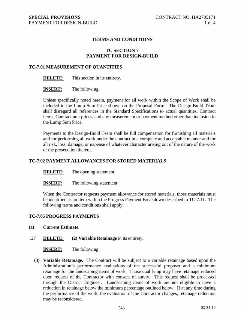
SPECIAL PROVISIONS CONTRACT NO. HA2705171 PAYMENT FOR DESIGN-BUILD 1 of 4
03-24-10
TERMS AND CONDITIONS
TC SECTION 7 PAYMENT FOR DESIGN-BUILD
TC-7.01 MEASUREMENT OF QUANTITIES DELETE: This section in its entirety. INSERT: The following:
Unless specifically noted herein, payment for all work within the Scope of Work shall be included in the Lump Sum Price shown on the Proposal Form. The Design-Build Team shall disregard all references in the Standard Specifications to actual quantities, Contract items, Contract unit prices, and any measurement or payment method other than inclusion in the Lump Sum Price. Payments to the Design-Build Team shall be full compensation for furnishing all materials and for performing all work under the contract in a complete and acceptable manner and for all risk, loss, damage, or expense of whatever character arising out of the nature of the work or the prosecution thereof.
TC-7.02 PAYMENT ALLOWANCES FOR STORED MATERIALS DELETE: The opening statement: INSERT: The following statement:
When the Contractor requests payment allowance for stored materials, those materials must be identified as an Item within the Progress Payment Breakdown described in TC-7.11. The following terms and conditions shall apply:
TC-7.05 PROGRESS PAYMENTS (a) Current Estimate. 127 DELETE: (2) Variable Retainage in its entirety. INSERT: The following: (3) Variable Retainage. The Contract will be subject to a variable retainage based upon the
Administration’s performance evaluations of the successful proposer and a minimum retainage for the landscaping items of work. Those qualifying may have retainage reduced upon request of the Contractor with consent of surety. This request shall be processed through the District Engineer. Landscaping items of work are not eligible to have a reduction in retainage below the minimum percentage outlined below. If at any time during the performance of the work, the evaluation of the Contractor changes, retainage reduction may be reconsidered.

SPECIAL PROVISIONS CONTRACT NO. HA2705171 PAYMENT FOR DESIGN-BUILD 2 of 4
03-24-10
Except for landscaping items of work, after 15 percent project completion and upon request, Contractors with 'A' evaluations for the last two years may be reduced from 5 percent to zero percent. Project completion percentage will be based upon actual work completed (excluding monies paid for stored materials). An interim evaluation of the current project would need to be completed and would need to be an 'A'. Except for landscaping items of work, at 50 percent project completion and upon request, Contractors with 'B' evaluations or any combination of 'A' and 'B' evaluations for the last two years may be reduced from 5 percent to 2.5 percent, and remain at that level until released upon final payment. Project completion percentage will be based upon actual work completed (excluding monies paid for stored materials). An interim evaluation of the current project would need to be completed and would need to be an 'A' or 'B'. Contractors with 'C' evaluations or any combination of 'C' and 'D' evaluation for the past two years will begin and remain at 5 percent for the life of the project, except for landscaping items. Contractors with a 'D' evaluation for the last two years will begin at 5 percent, except for landscaping items. Project performance will be evaluated monthly with the retainage being raised to 10 percent, except for landscaping items, for continued 'D' performance. New Bidders. Contractors who have not been previously rated by the Administration may be eligible for a reduction in retainage. To be eligible, their past performance on highway and bridge work shall be documented by the government agency with which they had a contract and their performance shall be documented on Administration forms. Contractors who do not fit into the above criteria would require a 5 percent retainage throughout the life of the Contract, except for landscaping items of work. Landscaping Items of Work. For all landscaping items of work, the retainage shall be 25 percent for the life of the project. Project performance will be evaluated monthly with the retainage being raised to 30 percent for neglect, improper maintenance, or failure to complete operations as required or directed. This retainage will be paid to the Contractor only at the final payment.
(b) Semi-Final Estimate Payments. 129 DELETE: Delete the entirety of subsections (1), (2), and (3). INSERT: The following:
(1) Upon completion of the project and the acceptance by the Administration for maintenance,
the Administration, at the Contractor’s request and with the consent of surety, will initiate a Memorandum of Action by the Director, Office of Construction, State Highway Administration, authorizing semi-final payment. Such a semi-final estimate payment will be based upon: (a) quantities the Administration has computed and set up as proposed final quantities, and (b) a reasonably accurate estimate for those quantities for which the Administration has not yet completed computations. The quantities that the Administration

SPECIAL PROVISIONS CONTRACT NO. HA2705171 PAYMENT FOR DESIGN-BUILD 3 of 4
03-24-10
sets forth as proposed final quantities shall be so designated. To arrive at the amount of the semi-final estimate, the following will be deducted from the apparent estimated value of the Contract: (a) total of all amounts previously paid to the Contractor as current estimates, (b) the retainage for landscaping items of work, (c) sums deemed chargeable against the Contractor including penalties and liquidated damages, and (d) as an additional retainage, a sum not less than 1 percent of the total value of the Contract, excluding landscaping items of work.
(2) In cases where there has been substantial completion of the project and there are remaining
only inconsequential or minor work items such as painting, seeding, mulching, or planting to be completed and such items cannot be completed for an extended period of time because of seasonal or weather conditions, a semi-final inspection will be made. If the work completed is found to be satisfactory, then there is deemed to be a partial acceptance on the entire project except for the uncompleted work items. Upon the above referred to partial acceptance, the Administration, within 30 days from such partial acceptance, upon request of the Contractor and with consent of surety, shall pay to the Contractor, what is hereby known as a partial semi-final estimate payment. Such a semi-final estimate will be based upon: (a) quantities the Administration has computed and set up as proposed final quantities, and (b) a reasonably accurate estimate for those quantities for which the Administration has not yet completed computations. The quantities that the Administration sets forth as proposed final quantities shall be so designated. To arrive at the amount of the semi-final payment, the following will be deducted from the apparent estimated value of the Contract: (a) total of all amounts previously paid to the Contractor as current estimates, (b) the retainage for landscaping items of work, (c) sums deemed chargeable against the Contractor including penalties and liquidated damages, and (d) as an additional retainage, a sum not less than 1 percent of the total value of the Contract, excluding landscaping items of work.
(3) If all retained funds have not been paid to an escrow agent, as provided for in (a)(4), the
Administration shall, upon payment of the semi-final estimate, place the remaining retainage in a interest-bearing escrow account, as designated and on such terms and conditions as specified by the procurement officer. At the time of the final payment, any retainage due, and any interest accrued on the retainage due from the time of payment of the semi-final estimate, shall be paid to the Contractor.
130 ADD: The following at the end of Section TC-7.05: (c) Application for Progress Payment.
In order to receive payment, the Design-Build Team shall submit a written Application for Progress payment to the Administration on a monthly basis. Receipts, invoices, and other vouchers, including invoices from subcontractors shall be included. Invoices shall be based on the proportionate quantities of the various classes of work satisfactorily designed, checked, and completed or incorporated in the work in accordance with the Schedule of Work and the value thereof determined from the Contract Progress Payment Breakdown as described in TC-7.11. If the Application for Progress Payment is inconsistent with the Payment Breakdown, the Projected Schedule of Payments, or the actual progress of work, the Application

SPECIAL PROVISIONS CONTRACT NO. HA2705171 PAYMENT FOR DESIGN-BUILD 4 of 4
03-24-10
must include a written explanation for such inconsistencies and the Administration reserves the right to withhold the applicable payment in whole or in part.
(d) Payment of Invoices.
All invoice payments shall be subject to correction in subsequent invoices and payments and upon final acceptance and payment. No payment shall be made when, in the judgment of the Administration, the work is not proceeding in accordance with the provisions of the Contract or when the total value of the work done since the last estimate amounts to less than $500.00. Portions of the progress payment may be withheld in accordance with the Contract provisions.
(e) Payment for Mobilization.
The total of payments for Mobilization will not exceed 10% of the Contract Price (less price adjustments and incentives).
(f) Payment for Changes. Differing site conditions, changes, and extra work meeting the requirements of this Contract will be paid using the following methods as appropriate: a. Unit prices agreed upon in the order authorizing the work. b. An agreed upon lump sum amount. c. On a Force Account basis, if agreement cannot be reached and if directed by the
Administration. Refer to TC-7.03 TC-7.10 COST BREAKDOWN AND SCHEDULE OF PAYMENTS .01 Submittal of Cost Breakdown
Within 10 days of the submission of the Price Proposal, the apparent low bid Design-Build Team shall submit to the Administration and itemized Cost Breakdown and supporting documentation to be used to evaluate bids and as a basis of payment. This breakdown shall present a realistic and documentable presentation of the costs for the major elements of work that comprise the lump sum price for the work. The breakdown shall be sent to the Director, Office of Highway Development, Mr. Kirk G. McClelland. At a minimum, the following Lump Sum Items shall be included: Clearing & Grubbing Mobilization (refer to TC-705,e.) Design Engineering As-Built Drawings Engineer’s Office Maintenance of Traffic

SPECIAL PROVISIONS CONTRACT NO. HA2705171 PAYMENT FOR DESIGN-BUILD 5 of 4
03-24-10
Construction Stakeout Earthwork - Excavation & Embankment Drainage Erosion & Sediment Control Structures (if applicable) Noise Walls (if applicable) Paving Items – hot mix asphalt, concrete pavement, and graded aggregate base Concrete Fencing Seed & Mulch Landscaping Lighting & Electrical Pavement Markings Permanent Signing Signals Utility costs for each utility – engineering and construction (if applicable) W-beam and concrete barrier City of Aberdeen Sewer Relocations Design City of Aberdeen Sewer Relocations Construction Harford County Water Relocations Design Harford County Water Relocations Construction The Administration may require additional items to be identified and included prior to approval Note that to enable the Administration to make effective progress payments, the successful Design-Build Team will be required to submit for approval the more detailed Progress Payment Breakdown described in TC-7.11. All progress payments will be based on an approved Progress Payment Breakdown. The Progress Payment Breakdown may be submitted in place of the Cost Breakdown described above. All costs associated with the preparation, submission, or revision of any Cost Breakdown will not be considered as an item for payment, but shall be included in the Design-Build Team’s Lump Sum price. The successful Design-Build Team will be required to submit an Initial Critical Path Method Project Schedule Design-Build Activities Chart within twenty (20) working days after notification of Award. This is in addition to the requirements outlined in Section 112- Critical Path Method Project Schedule Design-Build.
.02 Review and Approval
Within 14 working days after Execution of the Contract, the Administration shall approve the Cost Breakdown or return it to the Design-Build Team with deficiencies noted. The Administration will not approve a Contract Cost Breakdown that is unbalanced. The Design-Build Team shall then submit the Cost Breakdown until an acceptable Cost Breakdown is approved. The Design-Build Team is responsible for

SPECIAL PROVISIONS CONTRACT NO. HA2705171 PAYMENT FOR DESIGN-BUILD 6 of 4
03-24-10
incorporating time for submission and approval of the Cost Breakdown in its Schedule of Work.
.03 Projected Schedule of Payments
Within 7 working days after approval of the Cost Breakdown, the Design-Build Team shall provide the Administration with a Projected Schedule of Payments for the Project. This schedule will provide the Administration with an estimate of monthly cash flow requirements by forecasting the Design-Build Team’s monthly Applications for Progress Payments for the duration of the Project. The Projected Schedule of Payments must be in accordance with the Contract, the approved Cost Breakdown.
.04 Justification of Cost Breakdown or Projected Schedule of Payments
The Administration may require the Design-Build Team to provide explanations and supporting documentation if the Cost Breakdown or Projected Schedule of Payments indicate unbalancing or do not reasonably reflect the actual cost of performing the work or the value of work received by the Administration.
TC-7.11 CONSTRUCTION PROGRESS PAYMENT BREAKDOWN .01 Submittal of Progress Payment Breakdown
The successful Design-Build Team shall submit to the Administration an itemized Progress Payment Breakdown and supporting documentation to be used as a basis for payment. This breakdown shall be a realistic and documentable presentation of the costs for the major elements that comprise the Contract Lump Sum price for the work. The breakdown shall be sent to the District Engineer. No progress payment will be made until such time that this breakdown has been accepted by the Administration. The Design-Build Team shall submit additional updates to the Payment Breakdown as the design and construction progresses and as directed by the Administration. The Administration reserves the right to request additional detail from the Design-Build Team in order to process progress payments. The breakdown shall be in MS Excel format and include at a minimum, the following items.
Section 1000
LS for Design Costs LS for Mobilization (refer to TC-7.05, e.) LS for As-Builts LS for Clearing & Grubbing LS for Engineer's Office LS for Maintenance of Traffic LF of Temporary Barrier LF of Temporary Striping SF of Temporary Signs
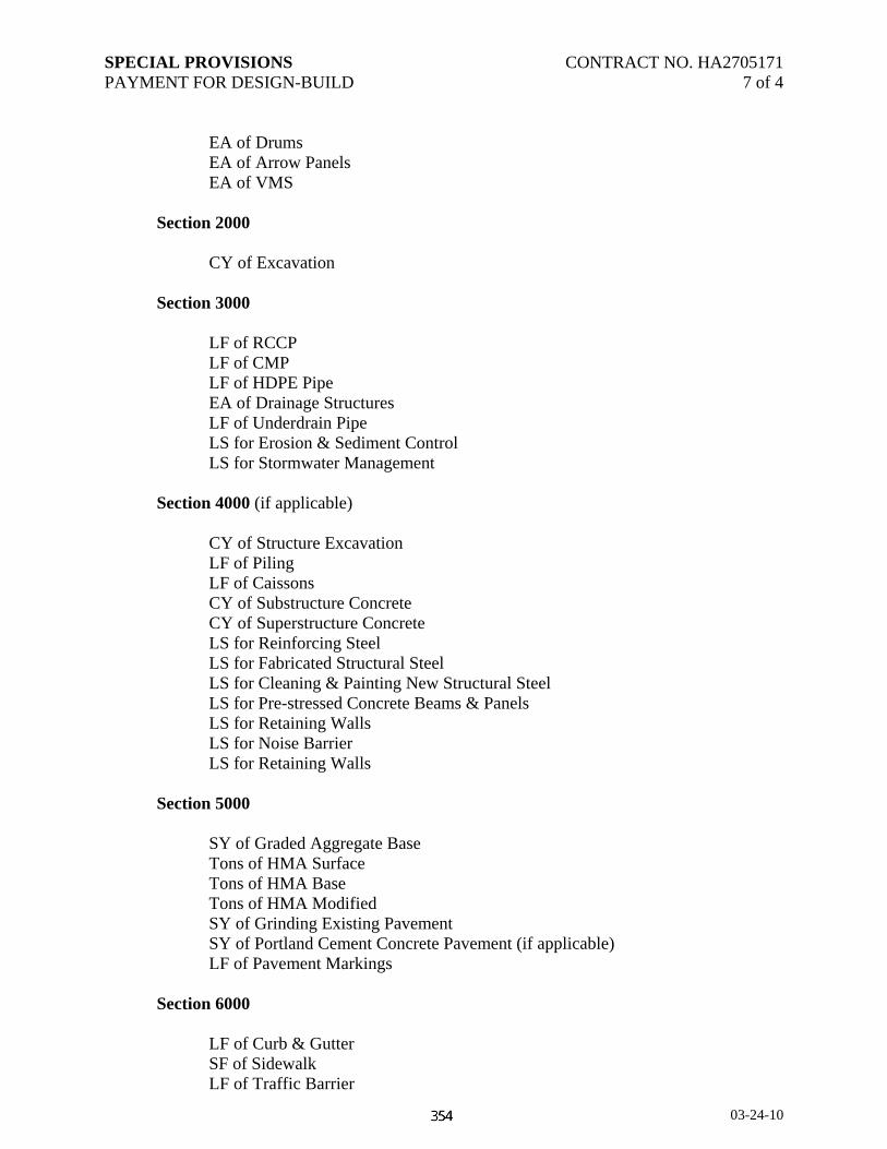
SPECIAL PROVISIONS CONTRACT NO. HA2705171 PAYMENT FOR DESIGN-BUILD 7 of 4
03-24-10
EA of Drums EA of Arrow Panels EA of VMS
Section 2000
CY of Excavation Section 3000
LF of RCCP LF of CMP LF of HDPE Pipe EA of Drainage Structures LF of Underdrain Pipe LS for Erosion & Sediment Control LS for Stormwater Management
Section 4000 (if applicable) CY of Structure Excavation LF of Piling LF of Caissons CY of Substructure Concrete CY of Superstructure Concrete LS for Reinforcing Steel LS for Fabricated Structural Steel LS for Cleaning & Painting New Structural Steel LS for Pre-stressed Concrete Beams & Panels LS for Retaining Walls LS for Noise Barrier
LS for Retaining Walls Section 5000 SY of Graded Aggregate Base Tons of HMA Surface Tons of HMA Base Tons of HMA Modified SY of Grinding Existing Pavement SY of Portland Cement Concrete Pavement (if applicable) LF of Pavement Markings Section 6000 LF of Curb & Gutter SF of Sidewalk LF of Traffic Barrier

SPECIAL PROVISIONS CONTRACT NO. HA2705171 PAYMENT FOR DESIGN-BUILD 8 of 4
03-24-10
EA of Traffic Barrier End Treatments LF of Concrete Traffic Barrier LF of Chain Link Fencing Section 7000 SY of Topsoil SY of Permanent Seeding SY of Temporary Seeding SY of Soil Stabilization Matting LS for Tree, Shrub, Perennial Establishment LS for Care & Replacement, Warranty of Plantings
Section 8000 CY of Concrete for Foundations LS for Sign Structures SF of Permanent Signing EA of Lighting Structures EA of Signal Structures LF of Wire, Conduit for Lighting and Signals
The breakdown shall also contain the Design-Build Team unit prices for Hot Mix Asphalt, HMA for Pavement Patching, each type of concrete mix to be used on the project, and each type of pavement marking. These prices will be used to determine a reduction in payment if necessary due to materials not meeting required specifications such as PCC compressive strength, AC content, asphalt density, pavement marking thickness, and reflectivity. Additionally, the breakdown shall include the hourly rate, including overhead, for each Design Key Staff member. This price will be used by the Administration to set a baseline cost associated with any work determined to be out of scope and agreed to by the Administration prior to the work being performed. The Design-Build Team shall use the Progress Payment Breakdown format in preparing and documenting its Applications for Payment. The Administration will use the Cost Breakdown to assist in evaluating requests for payment. All costs associated with preparation, submission, or revision of the Progress Payment Breakdown will not be considered as an item for payment, but shall be included in the Design-Build Team’s Lump Sum price.

SPECIAL PROVISIONS CONTRACT NO. HA2705176 REMOVAL AND DISPOSAL OF ABOVE GROUND STORAGE TANKS 1 of 2
omtsp 04-19-10
CATEGORY 100 PRELIMINARY SECTION 102-REMOVAL AND DISPOSAL OF ABOVE GROUND STORAGE TANKS
DESCRIPTION. This work shall consist of removal and disposal of Above Ground Storage Tank (AST). MATERIALS. Common Borrow 916.01
CONSTRUCTION. The AST shall be removed by a Certified Tank Removal Technician licensed to remove AST’s in conformance with COMAR regulations.
There is a potential that petroleum contaminated soils may be encountered during the removal of the AST. The presence of the petroleum contaminated material may require action to ensure a safe work environment. The Contractor shall adopt a health and safety plan prepared by a Certified Industrial Hygienist that monitors contaminated zones during excavation. Costs of worker safety issues are incidental to the appropriate Contract items.
Material exhibiting a petroleum odor shall be used or disposed of at the discretion of the Engineer. Material containing excessive petroleum contaminates shall be disposed of in accordance with State and County Regulations. Contamination greater than 100 parts per million volatile organic compounds (VOC), when measured by the photoionization detector, shall be considered excessive, unless otherwise determined by the Engineer. Materials with less than 10 parts per million VOC may be used without restrictions. Materials with VOC concentrations between 10 and 100 parts per million will be disposed of or utilized at the discretion of the Engineer. The Contractor is advised that dewatering operations may produce petroleum contaminated water that will require disposal. Petroleum contaminated water shall be disposed of in accordance with State and County Regulations.
Any excavated areas shall be backfilled with Common Borrow as directed by the Engineer.
SPECIAL PROVISIONS CONTRACT NO. HA2705176 REMOVAL AND DISPOSAL OF ABOVE GROUND STORAGE TANKS 2 of 2
omtsp 04-19-10
MEASUREMENT AND PAYMENT. Payment for the removal and disposal of the AST shall be lump sum. The lump sum will be full compensation for removal and disposal of the AST, and contents, disposal of hazardous material, removal and disposal of petroleum contaminated soil material, removal and disposal of petroleum contaminated water, backfilling with common borrow, all excavation, safety measures, labor, equipment, sampling and testing of the AST’s contents, tools, necessary permits, and incidentals necessary to complete this work.

SPECIAL PROVISIONS CONTRACT NO. HA2705176 REMOVAL AND DISPOSAL OF UNDERGROUND STORAGE TANKS 1 of 2
omtsp 01-13-10
CATEGORY 100 PRELIMINARY SECTION 102-REMOVAL AND DISPOSAL OF UNDERGROUND STORAGE TANKS
DESCRIPTION. This work shall consist of removal and disposal of Underground Storage Tanks (UST), removal of the existing pumps, concrete pavement adjacent to the pumps and UST, located at approximately at Sta. 128+00 100’ left MD Rte. 715. MATERIALS. Common Borrow 916.01
CONSTRUCTION. The UST’s and shall be removed by a Certified Tank Removal Technician licensed to remove UST’s in conformance with COMAR regulations.
There is a potential that petroleum contaminated soils may be encountered during the excavation on the project. The presence of the petroleum contaminated material may require action to ensure a safe work environment. The Contractor shall adopt a health and safety plan prepared by a Certified Industrial Hygienist that monitors contaminated zones during excavation. Costs of worker safety issues are incidental to the appropriate Contract items.
Material from excavation exhibiting a petroleum odor shall be used or disposed of at the discretion of the Engineer. Excavated material containing excessive petroleum contaminates shall be disposed of in accordance with State and County Regulations. Contamination greater than 100 parts per million volatile organic compounds (VOC), when measured by the photoionization detector, shall be considered excessive, unless otherwise determined by the Engineer. Materials with less than 10 parts per million VOC may be used without restrictions. Materials with VOC concentrations between 10 and 100 parts per million will be disposed of or utilized at the discretion of the Engineer. The Contractor is advised that dewatering operations may produce petroleum contaminated water that will require disposal. Petroleum contaminated water shall be disposed of in accordance with State and County Regulations.
The Excavated areas shall be backfilled with Common Borrow as directed by the Engineer.

SPECIAL PROVISIONS CONTRACT NO. HA2705176 REMOVAL AND DISPOSAL OF UNDERGROUND STORAGE TANKS 2 of 2
omtsp 01-13-10
MEASUREMENT AND PAYMENT. Payment for the removal and disposal of the UST’s, removal of the existing pumps, and concrete pavement adjacent to the pumps and UST shall be lump sum. The lump sum will be full compensation for removal and disposal of the UST’s, and contents, disposal of hazardous material, removal and disposal of petroleum contaminated soil material, removal and disposal of petroleum contaminated water, backfilling with common borrow, all excavation, safety measures, labor, equipment, sampling and testing of the UST’s contents, tools, necessary permits, and incidentals necessary to complete this work. Disposal of all excess and unsuitable material is considered incidental to the lump sum price.

SPECIAL PROVISIONS INSERT CONTRACT NO. HA2705171 103 ⎯ ENGINEERS OFFICE 1 of 1
10-06-09
CATEGORY 100 PRELIMINARY
SECTION 103 ⎯ ENGINEERS OFFICE
103.03 CONSTRUCTION.
103.03.05 Requirements for all Offices.
144 ADD: the following after (v).
(w) One paper shredder capable of shredding at least 10 sheets (20 lb bond) at a time. Throat width of at least 12 in. Speed of at least 20 feet per minute. Auto reverse or auto stop for paper jams. Power of at least 115 v.
146 DELETE: 103.03.09 Recyclable Materials (Paper, Bottles, Cans, Etc.) in its entirety.
INSERT: The following. 103.03.09 Recycling. Recycling of recyclable paper (bond, newsprint, cardboard, mixed paper, packaging material and packaging), bottles (glass and plastic), and aluminum cans will be required at the Engineer’s Office and the Contractor’s facilities for the project. Furnish approved containers, and remove the material from the site on an approved schedule or as directed. All material shall be taken to an authorized recycling facility. Maintain a log for the duration of the project documenting the type of materials recycled. The log shall include the types of material, date, time, location of facility, and signature line. Furnish a copy of the log at the completion of the project and upon request. The Contractor shall be considered the owner of any profit and be responsible for all incurred costs.

SPECIAL PROVISIONS CONTRACT NO. HA2705171 103 — ENGINEERS OFFICE 1 of 3
10-06-09
CATEGORY 100 PRELIMINARY
SECTION 103 – ENGINEERS OFFICE
144 DELETE: 103.03.06 Microcomputer System for all Offices in its entirety. INSERT: The following. 103.03.06 Computer System. Furnish 1 desktop computers and 0 laptop computers. General Requirements.
(a) IBM compatible with an Intel or AMD processor. (b) Minimum hard drive storage of 80 GB (gigabyte). (c) One CD-RW drive (re-writable CD-ROM). (d) Operating System. Minimum Microsoft® Windows XP PRO SP2. Must be a 32-bit
operating system. (A 64-bit operating system is not compatible with some SHA software.) The computer system will not be acceptable unless all Microsoft Windows Critical Updates are installed.
(e) Printer. When an Engineers Office is specified, furnish a B&W laser jet printer with a
minimum resolution of 1200 DPI (dots per in.), at least 8 MB of RAM, and a print speed of at least 15 PPM (pages per minute). Inkjets will not be accepted. (Note: A separate color inkjet printer shall be required if a digital camera is specified, refer to SP-Section 113).
(f) Software. Supply all manuals and software on original disks for retention in the Engineers
Office or Administration facility for the duration of the Contract.
(1) Microsoft® Office 2007 Professional for Windows™ or later. (2) Install and configure antivirus software to perform an automatic update when the
microcomputer system connects to the internet. Antivirus software approved for Administration web email: *Norton, McAfee, Sophos, or ETrust. (*Norton Internet Security includes Antivirus and a Personal Firewall).
(g) Internet Access. Provide unlimited internet service approved by the Engineer. Where available, provide internet high-speed service (DSL or cable). With DSL or cable internet service, provide an external router device. Provide firewall software to protect the computer from security intrusions.
SPECIAL PROVISIONS CONTRACT NO. HA2705171 103 — ENGINEERS OFFICE 2 of 3
10-06-09
(h) Accessories. (1) When an Engineers office is specified, provide a standard computer workstation with
minimum desk space of 60 X 30 in. and a padded swivel type chair with armrests. (2) 8-1/2 X 11 in. xerographic paper as needed. (3) Toner or ink for the printer as needed. (4) Maintenance agreement to provide for possible down time. (5) Physical security system to deter theft of the computer and components. (6) Three 4-GB USB flash drive storage devices. (7) Blank recordable CD-RW media as needed.
Desktop Specific Requirements. (a) Minimum processor speed of 3.0 GHz. (b) Minimum of 2 GB RAM (Random Access Memory). (c) Enhanced 101 key keyboard with wrist rest. (d) Super video graphics accelerator (SVGA). (e) Mouse and mouse pad. (f) Flat-panel LCD monitor (19 in. minimum) meeting Energy Star requirements. (g) Uninterruptible power supply (UPS).
Laptop Specific Requirements. (a) Must meet military standard of durability MIL-STD 810G (b) Minimum processor speed of 2.4 GHz. (c) Minimum 2 GB SDRAM. (d) Minimum 15” 1024x768 (XGA), daylight-readable, 500nits (cd/m2) LCD display.

SPECIAL PROVISIONS CONTRACT NO. HA2705171 103 — ENGINEERS OFFICE 3 of 3
10-06-09
(e) Power Supply. Two lithium ion battery packs with overcharge protection, an AC adaptor, and a vehicle DC power adaptor that operates the laptop and simultaneously charges the laptop’s internal battery.
(f) Carrying Case. (g) Printer. When an Engineers Office is not specified, furnish a portable printer that meets the
requirements specified above. (h) Internet Service. If an Engineers office is not specified, furnish the laptop with an internal
wireless broadband card and broadband internet service. Have the computer system completely set up and ready for use on or before the day the Engineers office is to be occupied. When an Engineers office is not specified, have the computer system furnished complete and ready for use at least five days prior to beginning any work on the project. If for any reason the system fails to operate, is stolen, or is otherwise unavailable for use, it shall be replaced or repaired within 48 hours. When the computer system is no longer required, the Construction Management software system including original user/operator guide manuals, program disks, and all data files (including those stored on USB flash drives, CD-R’s, etc.) will be removed by the Engineer and delivered to the District Engineer and become the property of the Administration. The remaining computer systems shall remain the property of the Contractor.
103.04 MEASUREMENT AND PAYMENT. 147 ADD: The following as a fourth paragraph.
Computer. The computer system will not be measured but the cost will be incidental to the Contract price for the Engineers Office item. If an item for Engineers Office is not specified, the cost of the computer system will be incidental to the payment for Mobilization. In absence of either item, payment will be incidental to the other items specified in the Contract Documents.


SPECIAL PROVISIONS CONTRACT NO. HA2705171 104.11 — TEMPORARY PAVEMENT MARKINGS 1 of 2
10-31-08
CATEGORY 100 PRELIMINARY
SECTION 104 — MAINTENANCE OF TRAFFIC
166 DELETE: Section 104.11 TEMPORARY PAVEMENT MARKINGS. in its entirety. INSERT: The following. 104.11 TEMPORARY PAVEMENT MARKINGS. 104.11.01 DESCRIPTION. Furnish, install, and remove temporary pavement markings as specified in the Contract Documents or as directed by the Engineer. These markings shall include lines, letters, numbers, arrows, and symbols. 104.11.02 MATERIALS. Removable Preformed Pavement Marking Material Refer to the Nontoxic Lead Free Waterborne Pavement Markings Contract Documents Black Out Tape QPL 104.11.03 CONSTRUCTION. 104.11.03.01 Quality Assurance/Quality Control. Quality control testing shall be completed by the Contractor’s Administration certified technicians. The Engineer will complete the quality assurance checks in conformance with MSMT 729 by performing the Nighttime Visibility Evaluations. 104.11.03.02 Warranty Period. The Contractor shall maintain and be responsible for any defects in the pavement markings for a period of 180 days from the date of application. The Contractor shall replace the pavement markings as necessary within this period as directed by the Engineer at no additional cost to the Administration. Refer to GP-5.11. 104.11.03.02 Application and Removal. The pavement markings shall be applied in conformance with the manufacturer’s recommendations and the Contract Documents. Markings shall be applied in the same direction as the flow of traffic. The markings shall be located as specified in the Contract Documents or as directed by the Engineer. Pavement markings may be applied to either new or existing paved surfaces. When applied to newly paved surfaces, the markings shall be placed before traffic is allowed on the pavement. Nontoxic lead free waterborne pavement markings shall be used for all temporary pavement markings except for the final surface. However, the Contractor may use removable preformed pavement markings at no additional cost to the Administration. When at the “end of season”, the temperatures are too low to allow the placement of removable tape on the final surface, a written exception request may be submitted to the Engineer to allow the use of nontoxic lead free waterborne paint in lieu of removable tape until the following striping season. When it is appropriate to shift lanes, all nonapplicable pavement markings within the travel way and adjacent to the travel way as directed by the Engineer shall be completely removed.
SPECIAL PROVISIONS CONTRACT NO. HA2705171 104.11 — TEMPORARY PAVEMENT MARKINGS 2 of 2
10-31-08
Surface Condition. Prior to application of pavement markings, the pavement surface shall be clean, dry, and free of all contaminants, including curing compound, dirt, and loose particles. Residual pavement markings shall be removed. Loose or poorly constructed markings shall also be removed. Pavement Marking Removal. All removable preformed pavement markings shall be completely removed prior to application of the permanent markings. On stage construction or final surfaces of portland cement concrete pavements, any objectionable adhesive residue shall be removed by water blasting or other methods as may be approved by the Engineer. Open flame is prohibited to remove adhesive residue, or any pavement markings. The Contractor shall remove all nonapplicable pavement markings so that there is no damage to the existing or final surface. Retroreflectance. The initial retroreflectance readings for temporary pavement markings shall be a minimum of 250 and 150 millicandellas/lux/square meter for white and yellow, respectively. The Engineer will monitor the pavement markings in conformance with MSMT 729 during the Contractor’s 180 day period of responsibility. 104.11.04 MEASUREMENT AND PAYMENT. Payment for Removable Preformed Pavement Markings, Removal of Removable Preformed Pavement Markings, Nontoxic Lead Free Waterborne Pavement Marking Paint, and the Removal of Existing Pavement Markings will be measured and paid for using one or more of the items listed below and as specified in the Contract Documents.
The payment will be full compensation for furnishing, placing, complete removal of lines, letters, numbers, arrows, symbols, and the removal of all residue. In addition, payment will cover maintenance and replacement during the 180 day period, and for all material, labor, equipment, tools, and incidentals necessary to complete the work. Removal and replacement of temporary pavement markings required beyond the 180 day period will be measured and paid for at the Contract unit price for the pertinent temporary pavement marking item. Temporary markings replaced during the 180 day period as a result of plowing (as determined by the Engineer) will be paid for at the Contract unit price for the pertinent temporary marking item. (a) Nontoxic Lead Free Waterborne Pavement Marking Paint-in width specified-per linear
foot. (b) Removable Preformed Pavement Line Markings-in width specified-per linear foot. (c) Removable Preformed Letters, Symbols, Arrows, and Numbers per each. (d) Removal of Removable Preformed Pavement Markings-any width-per linear foot. (e) Removal of Removable Preformed Letters, Symbols, Arrows and Numbers per each. (f) Removal of Existing Pavement Line Markings-any width per linear foot.
(g) Removal of Existing Letters, Symbols, Arrows, and Numbers per each.
(h) Black Out Tape Lines-in width specified-per linear foot.
(i) Removal of Black Out Tape Lines-any width-per linear foot.

SPECIAL PROVISIONS INSERT CONTRACT NO. HA2705171 104.14 — CONES FOR MAINTENANCE OF TRAFFIC 1 of 1
09-04-09
CATEGORY 100 PRELIMINARY
SECTION 104 — MAINTENANCE OF TRAFFIC
104.14 CONES FOR MAINTENANCE OF TRAFFIC. 104.14.02 MATERIALS.
171 DELETE: First paragraph on this page “Cones shall be…an upright position”. INSERT: The following. All cones shall meet MdMUTCD and be new or like new condition. All cones shall be orange in color. Cones shall be at least 28 in. high, 10 in. diameter at the inside of the base, and reflectorized with two white retroreflective stripes. The top stripe shall be 6 in. wide and located 3 to 4 inches from the top of the cone. The second stripe shall be 4 in. wide and located 2 inches below the top band. Tall-Weighted Cones. When specified, tall-weighted cones shall be at least 42 in. high and 7 in. diameter at the inside of the base. Tall-weighted cones shall be manufactured of low density polyethylene (LDPE) and have four high performance wide angle white and orange retroreflective stripes. The stripes shall be horizontal, circumferential and 6 in. wide. Alternate stripe colors with the top stripe being orange. Any nonretroreflective spaces between the orange and white stripes shall not exceed 1/2 in. 104.14.03 CONSTRUCTION. ADD: The following after the first paragraph “The Contractor’s name…away from traffic”. Equip all cones with approved weights or anchor collars, (15 lb maximum) as needed to maintain an upright position. Anchor collars shall fit to the base of the cone. For tall-weighted cones use anchor collars weighing 10 to 30 lb.

SPECIAL PROVISIONS CONTRACT NO. HA2705171 104.21 — CELLULAR TELEPHONES 1 of 1
10-06-09¶
CATEGORY 100 PRELIMINARY
SECTION 104 — MAINTENANCE OF TRAFFIC
104.21 CELLULAR TELEPHONES. 104.21.01 DESCRIPTION. Furnish and maintain new or like new cellular telephones for use by the appropriate Administration personnel. Each telephone shall be furnished with a hands-free device and be delivered to the Engineer at time of Notice to Proceed, fully activated and operational. They shall remain operational until returned to the Contractor at final acceptance of the entire project in conformance with GP-5.13. 104.21.02 MATERIALS. Cellular Telephones As approved by the Engineer 104.21.03 CONSTRUCTION. Not applicable.
104.21.04 MEASUREMENT AND PAYMENT. The number of cellular telephones required for this Contract is Four. The cellular telephones will not be measured but will be incidental to the Contract price for the Engineers Office item. If an item for Engineers Office is not specified, payment for the cellular telephones will be incidental to the payment for Mobilization. In the absence of either item, payment will be incidental to the other items specified in the Contract Documents. The payment will be full compensation for furnishing the telephones and hands-free devices, activation fees, battery replacement, monthly service fees, extended coverage charges, air time (peak and nonpeak time per minute), roaming rates, long distance fees in conformance with the schedules provided, and for all material, labor, equipment, tools, and incidentals necessary to complete the work. If any of the telephones become defective, are stolen, or for any other reasons do not function as intended, they shall be replaced in-kind at no additional cost to the Administration. Nonfunctioning or stolen telephones shall be replaced within eight hours after the Contractor is notified by the Engineer. Ownership of the telephones will remain with the Contractor. The Administration assumes no responsibility or liability for the condition of the telephones when they are returned.

SPECIAL PROVISIONS CONTRACT NO. HA2705171 104.25 — DRONE RADAR 1 of 1
10-31-08¶
CATEGORY 100 PRELIMINARY
SECTION 104 — MAINTENANCE OF TRAFFIC
104.25 DRONE RADAR 104.25.01 DESCRIPTION. Furnish, install, and relocate drone radar as specified in the Contract Documents or as directed by the Engineer. A drone radar consists of an electronic device that activates all types of on-board radar detectors without causing interference to normal police radar operations. 104.25.02 MATERIALS. Drone Radar As approved by the Office of Traffic and Safety General. The electronic device shall be capable of being securely mounted to a vertical or horizontal surface. The unit shall be of weatherproof and waterproof construction and operate efficiently from -20 to +160 F. FCC Equipment Authorization. The device shall bear an FCC Equipment Authorization for unlicensed use by the general public under FCC Title 47, Part 15. All applicable FCC equipment regulations shall be met without any additional licensing required of the Administration or the Contractor. Range. The drone radar shall have an effective linear range of at least 2600 ft. Power Source. 12 volts DC or 120 volts AC compatible/convertible. Current Consumption. 1/2 amp maximum. Frequency. 24.150 ± 0.100 GHz. 104.25.03 CONSTRUCTION. The drone radar shall be furnished, positioned, repositioned, operated, maintained, and removed, as needed or as directed by the Engineer. The unit may be truck or trailer mounted, fixed to a special lighting unit, portable changeable message sign, arrow panel, traffic sign, or traffic barrier W beam, as directed by the Engineer. 104.25.04 MEASUREMENT AND PAYMENT. Drone Radar will be measured and paid for at the Contract unit price per day. A unit day shall consist of any approved usage within a 24 hour calendar day. If a unit is used for part of a day, it will be measured as a unit day. The payment will be full compensation for drone radar unit, installation, power supply, wiring, supports, relocating as required by the Traffic Control Plan or as directed by the Engineer, removal, and for all material, labor, equipment, tools, and incidentals necessary to complete the work. Each Drone Radar device will be paid for only once per unit day, which will include any work necessary to maintain, re-align, or relocate the device; or replace damaged, missing or stolen devices.

SPECIAL PROVISIONS CONTRACT NO.HA2705171 104.30 — PORTABLE TRAFFIC SIGNAL 1 of 4
10-31-08
CATEGORY 100 PRELIMINARY
SECTION 104 – MAINTENANCE OF TRAFFIC
104.30 PORTABLE TRAFFIC SIGNAL (PTS). 104.30.01 DESCRIPTION. Furnish, install, and maintain a portable, self-contained, trailer mounted traffic signal for maintenance of traffic operations as specified in the Contract Documents or as directed by the Engineer. 104.30.02 MATERIALS.
Portable Traffic Signal (PTS) As Approved by Office of Traffic and Safety
Portable Traffic Signals (PTS) shall be trailer mounted units. This system shall consist of two or more trailers. Each unit shall be self-contained battery powered with solar assist, consist of two signal heads per trailer, non-intrusive vehicle detectors, and a solid state signal controller. One signal head shall be mounted on an overhead mast arm capable of extending over the travel lane. The other signal head shall be mounted on a vertical upright. The contractor shall have on-site a spare LED red, yellow and green display lens for the signal heads and a spare controller so that immediate repairs can be made in the event of a failure. The PTS shall have non-intrusive vehicle detectors and must be interconnected at all times with a twisted pair shielded cable as recommended by the manufacturer. The traffic signal shall have programmable minimum and maximum green times and a vehicle extension time that will extend the green to the maximum green time if the demand is present. The traffic signal shall have a programmable time of day feature that will allow the maximum green times to be changeable by time of day. The PTS shall have a manual control switch that will allow the Traffic Manager to manually control the signal to coordinate the PTS for special operations. The contractor shall have his personnel trained by the manufacturer on the set up, programming and operation of the PTS prior to its use. 104.30.03 CONSTRUCTION. Place PTS trailers in the closed lane during alternating one-lane, two-way traffic operations, without intruding into the travel lane, or as directed by the Engineer. Contractor shall make available provisions to have flagger control in place immediately to maintain traffic in case of PTS failure. Contractor shall have signal personnel available at all times to maintain and operate or repair the PTS as needed. The contractor shall be responsible for all setup procedures necessary for the PTS including setting up the trailers, aiming signal heads, interconnecting the signal controllers, aiming and adjusting vehicle detection units, and installing the timing provided by the District Traffic.
SPECIAL PROVISIONS CONTRACT NO.HA2705171 104.30 — PORTABLE TRAFFIC SIGNAL 2 of 4
10-31-08
104.30.03.01 Equipment. Trailer. The trailer shall conform to Maryland Motor Vehicle Law governing trailers. Support Structure. The PTS trailer shall be capable of accommodating a vertical upright and a horizontal mast arm. The trailer and all mounted equipment shall be structurally adequate for unlimited, normal operation in wind velocities typically encountered on the roadway (gusts of 80 MPH). No additional ballast shall be used to achieve the structural stability required for normal operation. Additional ballast includes but is not limited to, sand bags, concrete/cement blocks and steel, cast, or iron weights (secured or unsecured). PTS trailers shall be manufactured to accommodate the option of transporting two signal trailers with one vehicle. Each signal trailer shall be equipped with four stabilizing/leveling jacks, one on each corner of the trailer. The PTS trailer shall have adequate structural integrity to facilitate lifting and placing the PTS trailer as required. Lift Mechanism. The PTS shall contain a lift mechanism that is electric or electrically-assisted hydraulic or mechanically assisted manual mechanism capable of raising and lowering the mast arm. The mechanism shall be capable of being raised and lowered manually. The mast arm shall extend a minimum of 9 ft from the side of the trailer.
Signal Heads / Display Requirements. The PTS shall meet the physical display and operational requirements of conventional traffic signals as specified in Part IV of the Maryland Manual on Uniform Traffic Control Devices (MUTCD). Signal Heads shall be cast aluminum and have three, 12 in. LED indications, conforming to ITE Specifications for “Vehicle Traffic Control Signal Heads” and NEMA Standards TS1 and TS2. Signal heads shall be equipped with visors which extend beyond the signal head a minimum of 10 in. All signal housings shall have a black face and yellow housing. The signal heads shall have the ability to accommodate back plates and rotate horizontally 180 degrees. The PTS shall have a reversible signal head mounting feature which will allow the trailers to be placed in the same lane of traffic. Both signal heads shall be able to be rotated and locked into position to provide the optimum visibility to motorists. The overhead signal shall have a minimum clearance height of 17 ft measured from the bottom of the green indication to the road surface. The lower signal head shall be mounted to a vertical upright at a minimum height of 8 ft measured from the bottom of the green indication to the road surface. Power Requirements. Each PTS Trailer shall be equipped with batteries sufficient to operate the signal for a minimum of 21 days at 72 degrees (F) without charging. The charging system shall include 450 watts (minimum) of solar collection capability and an onboard battery charger capable of being used with a 110 volt power source. The system shall also include an onboard monitoring system capable of regulating and providing a visual display of the battery voltage and solar input. Operational Requirements. Each PTS shall be equipped with an operating system having the following capabilities:
(a) The signal controller shall be enclosed in a cabinet mounted on each trailer.

SPECIAL PROVISIONS CONTRACT NO.HA2705171 104.30 — PORTABLE TRAFFIC SIGNAL 3 of 4
10-31-08
(b) The controller shall be furnished with a keypad or LCD display screen to allow for the signal operator to program the signal under all weather conditions. The controller shall have the capability of connecting to a PC or laptop for programming.
(c) The signal controller shall operate between -30 and 150F and in a 20 to 100 percent humidity range.
(d) A conflict monitoring system conforming to NEMA Standards. (e) The capability of being operated in a fixed time, traffic actuated or manual control
mode. (f) Fixed time mode operation option must include the ability to provide a minimum of five
automatic signal timing changes within a 24-hour period. (g) The operating system shall have the ability to control a minimum of 7 traffic phases. (h) Programmable green times from 3 seconds to 250 seconds, yellow times from 1 second
to 6 seconds, and red times from 1 second to 250 seconds. All programmable times shall be in 1 second increments.
(i) The ability to facilitate minimum / maximum green time programming in the traffic actuation mode in a manner that will extend the green times in predetermined programmable segments as required.
(j) The operating system shall have the capability of facilitating standby modes of red, red flash and yellow flash mode.
(k) A work zone safety light shall be installed on the rear side of the upper signal head. This light shall illuminate when the traffic signal is displaying a solid red indication.
(l) The operating system shall be capable of facilitating traffic actuation with true presence capability.
(m) The operating system shall have the capability of interfacing with a remote monitoring system capable of reporting signal location, battery voltage and system default.
(n) The monitoring system shall not be limited to cellular phone coverage areas, and must remain operational regardless of location and weather conditions.
(o) The operating system shall have an integrated mechanism capable of recording system malfunctions including date and time of system failure. This information shall be available in a printable format.
(p) The operating system shall be capable of accommodating a pre-emption system with optical activation which provides a priority green phase in the direction of appropriately equipped approaching emergency vehicles.
(q) The operating system shall have the capability to allow the PTS to be connected to and controlled by a standard NEMA controller.
(r) The operating system shall be equipped with diagnostic capabilities in the event of a system default.
(s) The system shall have the capability of identifying the default in a manner that will expedite the return to full operational mode.
Actuation Requirements. The PTS systems shall be capable of utilizing non-invasive detectors for traffic actuation. Acceptable non-invasive detectors include microwave motion sensors and video detection cameras. Acceptable PTS systems shall have the capability of being operated with both a motion and true presence actuation system.

SPECIAL PROVISIONS CONTRACT NO.HA2705171 104.30 — PORTABLE TRAFFIC SIGNAL 4 of 4
10-31-08
Communication Requirements. The PTS systems shall have the capability of being operated using hardwired or wireless communication. The PTS shall be operated using hardwired communication unless otherwise directed by the Engineer. The communication cable shall be deployed in a manner that will not intrude in the direct work area of the project or obstruct vehicular and pedestrian traffic. If the radio link communication option is utilized clear line of sight must be maintained between PTS units and the radio system shall conform to the applicable Federal Communication Commission requirements and all applicable state and local requirements. Should there be a failure in the communication link between the two signals, both signals shall be display solid red indications. Default Requirements. PTS systems shall have the capability of reverting to a red, red flash or yellow flash mode upon system default. The default setting shall be solid red unless otherwise stated in the project specifications or as directed by the Engineer. Upon default the PTS system shall immediately contact a minimum of three responsible individuals via the remote monitoring system described in the Operational Requirement section. The work zone safety light shall flash if the system is in the default mode. The PTS system repairs shall be the responsibility of the contactor and shall be rendered in a manner that will return to PTS to full operation condition in the most expeditious manner. Field Operations. The contractor shall be responsible for setting up, programming, relocating and maintaining the PTS. The contractor shall notify the Assistant District Engineer Traffic at least 3 weeks prior to starting work so they can provide the signal timing. There will be no programming or timing changes to the PTS with out written approval from the Assistant District Engineer Traffic. The portable signal operation may be adjusted or reconfigured as directed by the Engineer as needed with the written approval of the Assistant District Engineer Traffic. The PTS shall operate as noted on the maintenance of traffic signalization plans. 104.30.04 MEASUREMENT AND PAYMENT. The Portable Traffic Signal will be measured and paid for at the Contract unit price per unit day. A unit day shall consist of any approved usage within a 24 hour day period. Each Portable Traffic Signal will be paid for only once per unit day, regardless of how many times it is relocated. When a unit is used for part of a day, it will be measured as a unit day. The payment will be full compensation for the provision, installation, operation, interconnection, maintenance, reconfiguration, adjustments, flaggers, repair technicians, relocation as required by the Traffic Control Plan or as directed by the Engineer, and for all materials, labor, equipment, tools, and incidentals necessary to complete the work.

SPECIAL PROVISIONS INSERT CONTRACT NO. HA2705171 104.31 ⎯ ACCESSIBLE PEDESTRIAN MAINTENANCE
OF TRAFFIC 1 of 2
10-31-08
CATEGORY 100 PRELIMINARY
SECTION 104 ⎯ MAINTENANCE OF TRAFFIC
104.31 ACCESSIBLE PEDESTRIAN MAINTENANCE OF TRAFFIC.
104.31.01 DESCRIPTION. Provide and maintain an accessible pedestrian route, to the “maximum extent feasible”, throughout the project’s limits. When an existing pedestrian access route within the public right of way is blocked by construction, alteration, or maintenance activity, an alternate accessible pedestrian route shall be provided. The phrase to the “maximum extent feasible” applies in areas where the nature of an existing facility or site conditions makes it virtually impossible to comply fully with applicable accessibility standards through a planned alteration. In these circumstances, the alternate accessible pedestrian route shall provide the maximum physical accessibility that is feasible, or a design waiver must be approved by SHA’s Office of Highway Development. 104.31.02 MATERIALS. Not applicable 104.31.03 CONSTRUCTION. The following considerations shall be taken into account when addressing accessible pedestrian maintenance of traffic:
(a) All pedestrians, including persons with disabilities, shall be provided with a reasonably safe, convenient and accessible path that replicates as much as practicable the existing pedestrian facilities.
(b) The width of the existing pedestrian facility should be maintained if practical. When it is
not possible to maintain a minimum width of 60 in. throughout the entire length of the pedestrian route, a minimum width of 36 in. shall be provided with 60 x 60 in. passing zones at least every 200 ft, to allow individuals in wheelchairs to pass.
(c) Traffic control devices and other construction materials and features shall not intrude into
the usable width of the sidewalk, temporary pathway or other pedestrian facility.
(d) Signs and other devices mounted lower than 7 ft above the temporary pedestrian pathway shall not project more than 4 in. into accessible pedestrian route.
(e) A smooth, continuous hard surface shall be provided throughout the entire length and
width of the pedestrian route throughout construction. There shall be no curbs or vertical elevation changes greater than 1/4 in. in grade or terrain that could cause tripping or be a barrier to wheelchair use. Vertical elevation differences between 1/4 in. and 1/2 in. shall be beveled at a maximum 2:1 slope. The slip resistance coefficient is .80 minimum using test method C 1028 (dry method).

SPECIAL PROVISIONS INSERT CONTRACT NO. HA2705171 104.31 ⎯ ACCESSIBLE PEDESTRIAN MAINTENANCE
OF TRAFFIC 2 of 2
10-31-08
(f) When channelization is used to delineate a pedestrian pathway, a continuous detectable edging should be provided throughout the length of the facility such that pedestrians using a white cane can follow it. Edging should protrude at least 6 in. above the surface of the sidewalk or pathway with the bottom of the edging a maximum of 2.5 in. above the surface
(g) Temporary ramps shall be provided when an alternate pedestrian route crosses a curb and
no permanent ramps are in place. The width of the ramp shall be a minimum of 36 in. and the slope of the ramp shall not exceed 10:1. Temporary detectable warning mats must be installed at street crossings and signalized entrances. The slip resistance coefficient is .80 minimum using test method C 1028 (dry method).
(h) When possible, an accessible pedestrian route shall be provided on the same side of the
street as the disrupted route. When it is not feasible to provide a same-side accessible pedestrian route an accessible pedestrian detour route shall be provided.
(i) Information regarding closed pedestrian routes, alternate crossings, and sign and signal
information shall be communicated to pedestrians with visual disabilities by providing devices such as audible information devices, accessible pedestrian signals or barriers and channelizing devices that are detectable to the pedestrians traveling with the aid of a white cane or who have low vision.
(j) It is desirable that pedestrians cross to the opposite side of the roadway at intersections
rather than mid-block. Appropriate signing shall be placed at the intersections.
(k) Access to transit stops shall be provided and maintained at all times. 104.31.04 MEASUREMENT AND PAYMENT. Unless otherwise specified, Accessible Pedestrian Maintenance of Traffic will not be measured but the cost will be incidental to the Lump Sum item for Maintenance of Traffic.

SPECIAL PROVISIONS CONTRACT NO. HA2705171 107-CONSTRUCTION STAKEOUT Page 1 of 5
03/02/2006
CATEGORY 100 PRELIMINARY
184 DELETE: SECTION 107 — CONSTRUCTION STAKEOUT in the Standard
Specifications in its entirety. INSERT: The following.
SECTION 107 — CONSTRUCTION STAKEOUT FOR DESIGN-BUILD PROJECTS 107.01 DESCRIPTION. This work shall consist of furnishing, placing and maintaining construction layout stakes as specified in the Contract Documents or as directed by the Engineer.
The Design-Builder shall, as part of the construction stakeout operation, before any clearing operation commences, demarcate any wetlands and the limit of clearing throughout the entire project as shown in the Contract Documents and labeled as Limit of Clearing or Wetlands to the satisfaction of the Engineer.
Where limits of clearing are not shown in the Contract Documents, the limit of clearing will be the top of cut, toe of slope or limit of ditch excavation. 107.02 MATERIALS. The material for flagging the clearing limits shall be a 3 in. international orange vinyl material with “CLEARING LIMIT” printed on it with 2 in. letters. The material for flagging wetlands shall be the Administration's standard 1-1/2 in. pink and white striped vinyl flagging with “SHA WETLAND” printed on it with blue letters. 107.03 CONSTRUCTION. 107.03.01 Line and Grade. The Design-Build Engineer will provide the Design-Builder with the following:
(a) Control Points. (1) Control Points for horizontal and vertical control shall be as shown on the
Preliminary Plans.

SPECIAL PROVISIONS CONTRACT NO. HA2705171 107-CONSTRUCTION STAKEOUT Page 2 of 5
03/02/2006
(b) Structure Stakeout.
(1) A staked out center line or working line, whichever applies, with stations not over 100 ft apart and extending at least 100 ft beyond ends of the structure.
(2) When the structure is on a curve, the Design-Build Engineer will furnish a
staked out center line or working line, whichever applies, consisting of stations not over 100 ft apart and including the P.C., P.T., and at least one point on the tangents beyond each end of the curve.
(3) At least two bench marks, one on each end of the structure, will be established
by the Design-Build Engineer. The Design-Builder will provide the following: (a) Roadway Stakeout. (1) A staked center line of the roadway with the maximum spacing of stations
(stakes, nails, crosses, etc.) of 100 ft. (2) Establish appropriately spaced bench marks and the necessary references
including all points of curvature (P.C.), and points of tangency (P.T.) for the preservation and control of the center line.
Horizontal Referencing:
• The Design-Builder will establish references to all Base Line of Construction Controls. This will include all Points of Curvature (P.C.s) and Points of Tangency (P.T.s).
• Reference points shall be positioned in pairs with the closest point placed Twenty (20) feet outside the limit of construction. Should these points fall beyond the Right of Way Line, approval from the property owner or tenant must be obtained prior to setting. Right angle and radial ties to Baselines are preferred but not required.
• Reference points, typically, shall be Number #5 (five) 5/8”Rebar two (2)feet long with a State Highway Administration(SHA) Yellow Cap affixed to the top. SHA Caps will be supplied by the SHA Plats and Surveys Division. In areas unsuitable for Rebars, markers of a stable, permanent nature shall be used,( crosses in concrete, PK nails, Railroad spikes, etc.) NOTE: Wooden hubs are not to be used for any referencing purpose.
• References, when positioned, shall be hand referenced to local points of permanency (trees, structure corners, utility poles, etc).measured to a 100th of a foot.

SPECIAL PROVISIONS CONTRACT NO. HA2705171 107-CONSTRUCTION STAKEOUT Page 3 of 5
03/02/2006
Vertical Referencing:
• The Design-Builder will place and establish permanent Bench Marks on structures along the project Baseline. These marks will be pre-stamped Brass Discs supplied by the S.H.A. Plats and Surveys Division and are to be placed in a suitable surface at time of pour and finish. In non-structure areas, permanent points in stable positions (Square cuts in existing concrete, Boat spikes in Power poles / large trees etc.) are acceptable.
• Benches shall be referenced to the Base Line of Construction by Station plus and offset distance.
• Spacing of Vertical Control shall be a minimum of Five (5) per mile. • Elevations on all Benches shall be established by differential leveling
and return Loop check. NOTE: In the Horizontal and Vertical Referencing process, all work shall be shown and
documented in SHA Field Survey book/s supplied by the S.H.A. Plats and Surveys Division. Upon project completion, all books shall be returned to the S.H.A. Plats and Surveys Division for archiving.
For questions regarding the S.H.A’.s specifications for Baseline Referencing or examples of S.H.A. Construction Stakeout bookwork, contact the S.HA.s Plats and Surveys Division in Baltimore, Maryland at 410-545-8940.
107.03.02 Equipment and Personnel. The Design-Builder shall engage a Registered Professional Land Surveyor, licensed in the State of Maryland, to determine all lines and elevations for various parts of the Work. The Surveyor shall have 3 to 5 years experience as a party chief or higher and have demonstrated experience working with the Maryland Plane Coordinate System – NAD 83/91 and NAVD 88, or similar. The surveyor shall use competent personnel and state of the art equipment for all engineering work required to set and maintain the elevations and dimensions as specified in the Contract Documents. 107.03.03 Control Markers. The Design-Builder shall be responsible for preserving the centerline and benchmarks set by the Design-Build Engineer. When the centerline and benchmarks are disturbed or destroyed, they shall be replaced by the Design-Builder at no additional cost to the Administration. 107.03.04 Control Stakes. For roadways as specified in 107.03.01, the Design-Builder shall furnish, set and preserve stakes at each station along each side of the project on the right-of-way or easement line, whichever is furthest from the center line of construction. Where only part of an ultimate dual highway is to be constructed, the stakes on the side of the future improvement shall be set 10 ft beyond the construction limits. On each of these stakes shall be marked its offset distance from the center line and its top elevation or the cut or fill to the profile grade line. Additional stakes as needed for horizontal and

SPECIAL PROVISIONS CONTRACT NO. HA2705171 107-CONSTRUCTION STAKEOUT Page 4 of 5
03/02/2006
vertical controls necessary for the correct layout of the work shall be set by the Design-Builder. 107.03.05 Layout. For structures as specified in 107.03.01, the Design-Builder shall proceed with the layout work. However, before any actual construction begins, the Design-Builder shall rerun and check the Design-Build Engineer's lines and grades and then establish all center line or working line intersections with the center line or center of bearing of all piers, bents and abutments. From these field layouts, the Design-Builder shall check the proposed span lengths by electronic distance measurement or chaining. When chaining is used, the measurements shall be compensated for temperature, sag, and horizontal alignment. The Design-Builder shall also check the location of the structure to affirm its correct location with relation to existing structures, roads, and existing conditions that are to remain in their original positions. If any discrepancies are found, the Design-Builder shall notify the Design-Build Engineer at once in writing, otherwise, it will be assumed that all planned dimensions, grades and field measurements are correct. All lines established on the ground shall be preserved or referenced, marked, and kept available at all times.
The Design-Builder shall establish the field elevations for all bridge seats and assume responsibility for finishing to proper grade. If any steel beams or girders are incorporated in the project, the Design-Builder shall run elevations over the tops of the beams or girders after they are in place, before any forms are attached to them, to determine the deflection of each member. This information shall then be applied to the deflection diagram to determine the corrected elevation of bottom slab forms and screed supports. After the Design-Builder has assembled this information, it will be checked by the Engineer before final adjustments are made and the placing of any concrete in the forms. 107.03.06 Utilities. The Design-Builder shall furnish to the utility companies or agencies working within the limits of the project, promptly upon request, reference to control points, alignment and grade data, so that they may properly locate and coordinate their work and improvements in relation to the project. Intersection Utility Stakeout. The Design-Builder shall notify the appropriate agencies listed below a minimum of 72 hours (excluding weekends and holidays) prior to the Design-Builder's anticipated beginning of any underground work. (a) Request a MISS UTILITY stakeout and possess a valid MISS UTILITY clearance
ticket number for any underground work. (b) Contact all utilities within the limits of the project who are not a member of MISS
UTILITY and obtain a stakeout of their respective facilities.

SPECIAL PROVISIONS CONTRACT NO. HA2705171 107-CONSTRUCTION STAKEOUT Page 5 of 5
03/02/2006
(c) Request the Office of Traffic & Safety's Signal Operations Section to stakeout Administration maintained traffic signal facilities.
(d) Request the District Engineer to stakeout their lighting facilities. The Design-Builder shall stakeout the proposed construction as indicated in the Contract Documents and allow the Design-Build Engineer to verify location of the proposed facilities. 107.03.07 Right-of-Way and Easement Lines. The Design-Builder shall define only right-of-way and easement lines of the project for adjacent property owners, promptly upon request. 107.03.08 Subgrade, Subbase and Base Controls. The Design-Builder shall furnish for subgrade, subbase and base courses, a string line and grade with fixed controls having a maximum longitudinal and transverse spacing of 25 ft. The Design-Builder shall place along each form line for cement concrete pavement line and grade with fixed controls not to exceed 25 ft. 107.03.09 Flagging. The flagging shall be placed continuously through wetland areas. In areas where trees are not to be disturbed, the Design-Builder shall individually flag those trees in a line along the clearing limits that are not to be moved or destroyed. If the clearing or wetland flagging has been destroyed and the Engineer determines that its use is still required, the Design-Builder shall reflag the areas If the Design-Builder does not replace destroyed flagging within 48 hours after notification by the Engineer that replacement flagging is needed, the Engineer may proceed to have the area reflagged. The cost of the reflagging by the Engineer will be charged to the Design-Builder and deducted from any monies due under the Contract. At the completion of construction, the Design-Builder shall remove all flagging. 107.04 MEASUREMENT AND PAYMENT. Payment for all work for Construction Stakeout FOR Design-Build Projects shall be included in the Lump Sum Price shown on the Schedule of Prices for the all-inclusive Project Lump Sum. The payment will be full compensation for furnishing, placing and maintaining construction layout stakes, flagging of clearing limits and wetlands, and for all material, labor, equipment, tools, and incidentals necessary to complete the work.

SPECIAL PROVISIONS CONTRACT NO. HA2705171 112 — CPM PROJECT SCHEDULE DESIGN-BUILD 1 of 7
07-01-08
CATEGORY 100 PRELIMINARY
SECTION 112 — CRITICAL PATH METHOD PROJECT SCHEDULE
DESIGN-BUILD 112.01 DESCRIPTION. This work shall consist of the Design-Build Firm planning, scheduling, and constructing the project by using a Critical Path Method Project Schedule (CPM). The CPM shall be used for coordinating and monitoring all the work specified in the Contract Documents including all activities of subcontractors, vendors, suppliers, utilities, railroads, the Administration, and all other parties associated with the construction of the Contract. All work including but not limited to submittals, major procurement, delivery, and construction activities shall be included. The CPM schedule shall be used for coordinating activities for both design and construction tasks by incorporating all activities into one CPM schedule. All work including but not limited to activities associated with design elements, milestones, permits, utility relocations, and submittals shall be represented by schedule activities. All appropriate schedule logic relationships between the design element activities and the corresponding construction activities shall be shown. The CPM shall be based upon the entirety of the Contract Documents. The software utilized for the CPM shall generate files that are compatible with Primavera Project Planner. Float. The CPM utilizes float. Float is defined as the amount of time between when an activity “can start or finish” and when an activity “must start or finish”. Float is a shared commodity for the use of the Administration and the Design-Build Firm and is not for the exclusive use or benefit of either party. The parties have the full use of the float until it is depleted. Scheduling Representative. The Design-Build Firm shall designate a scheduling representative, prior to submission of the Initial Critical Path Method Project Schedule (ICPM). The scheduling representative is the person primarily responsible for development and maintenance of the Design-Build Firm’s CPM schedule. The scheduling representative shall represent the Design-Build Firm in all matters regarding the schedule and shall attend all schedule related meetings. Replacement of the scheduling representative by the Design-Build Firm will require written approval from the Administration. The Design-Build Firm shall submit the qualifications of the designated scheduling representative to the Administration for approval. This approval is required before the ICPM will be accepted. The designated scheduling representative shall have at least three years of verifiable experience for preparing and maintaining CPM project schedules on Contracts of the same or similar size and complexity. Initial Critical Path Method Project Schedule (ICPM). The ICPM shall consist of: (a) A time scaled diagram. The ICPM time scaled diagram shall have a scale and format that
is acceptable to the Engineer. The activities shall be labeled with the activity identification clearly shown for each activity. All relationships between activities shall be shown.

SPECIAL PROVISIONS CONTRACT NO. HA2705171 112 — CPM PROJECT SCHEDULE DESIGN-BUILD 2 of 7
07-01-08
(b) Tabular reports with activities sorted as follows: (1) Activity ID. This report shall include predecessors and successors for each activity
with leads and lags shown. (2) Activity ID. This report shall include resources. This report shall clearly define the
resources assigned to each activity. (3) Early Start, Total Float. (4) Total Float, Early Start. (5) Project Area (if applicable). (6) Project Phase (if applicable). (7) Responsibility, e.g., Design-Build Firm, Designer, specific subcontractor, specific
supplier, the Administration, etc. (8) Other activity codes as required by the Engineer.
The header of each tabular report shall include the project name, Contract number, data date, run date and number, and report type.
The body of each report shall include the activity identification, activity description, original and remaining duration, early/late start and finish dates, percent complete, actual start/finish dates, total float, and calendar designation for every activity.
(c) Written Narrative (WN). The WN shall comply with the requirements described
hereinafter. (d) Printed Calendars. The printed calendars shall include a listing, description, and calendar
form tabulation of all calendars used in the ICPM. The calendars shall contain the total number of anticipated work days required to complete all the work required in the Contract. The calendars shall delineate the holidays and anticipated nonwork days or periods. An explanation of the Design-Build Firm’s basis for determining each nonwork day or period shall be included in the WN.
(e) Data disc containing all of the information contained in the CPM. The format shall be
compatible with Primavera Project Planner software. All construction activities shall have durations not exceeding 10 working days, unless otherwise approved by the Engineer. Activities representing review and approval of construction submittals by the Administration shall be given a duration of not less than 30 calendar days. Activities representing review and approval of design submittals by the Administration shall be

SPECIAL PROVISIONS CONTRACT NO. HA2705171 112 — CPM PROJECT SCHEDULE DESIGN-BUILD 3 of 7
07-01-08
given a duration of not less than 45 calendar days. The Design-Build Firm may submit a short list of highly critical approval activities to the Engineer. The Engineer will make every effort to expedite the approval of these submittals, however, this will not alter the requirements to include 30 calendar days for approval of construction activities and 45 calendar days for approval of design activities in the ICPM. Activities for curing, pre-load, etc. shall be scheduled in calendar days. Durations for procurement activities will be evaluated on a case by case basis. The latest calculated early finish date in the ICPM shall equal the Contract calendar date for completion specified in the Contract Documents. If the Design-Build Firm submits an earlier completion date than specified in the Contract Documents, the Administration, upon acceptance of the ICPM, will issue a change order to adjust the Contract time to the completion date shown on the ICPM. The Design-Build Firm shall resource load all construction activities in its schedule with the material, equipment, and manpower planned to be utilized by the Design-Build Firm and its subcontractors in accomplishing each activity. Resource loading of the CPM shall be fully explained in the WN. The Engineer reserves the right to specify the number of activities and to require at any time additional breakdown of the activities. The Design-Build Firm shall utilize activity codes to categorize activities by at least the following: project area; construction phase; design phase, and responsibility, e.g. Design-Build Firm or specific subcontractor. The Design Build Firm shall provide a WN as part of the ICPM. This WN shall explain the sequence of work, the critical path, interim completion dates, project phasing, nonwork days or periods, maintenance of traffic, and labor and equipment resources. In addition, the Design-Build Firm shall explain how it has provided for permit requirements, environmental requirements, coordination with other public contractors, milestone dates (for the Contract or other related contracts), coordination with other entities, coordination with all utility companies, special nonwork days or periods, and weather in its ICPM. The WN shall be used to explain the specific scope of each activity and the basis used to determine the original duration of each activity, i.e., production rates and anticipated quantities. All activities quantified in the Contract Documents shall be addressed in the WN. The Design-Build Firm shall utilize the WN to explain the following: (a) Relationships between activities not obviously identified. (b) Equipment usage and limitations. (c) Manpower usage and limitations. (d) Use of additional shifts and overtime.
SPECIAL PROVISIONS CONTRACT NO. HA2705171 112 — CPM PROJECT SCHEDULE DESIGN-BUILD 4 of 7
07-01-08
(e) Activity codes, abbreviations, and activity identification system. (f) All calendars utilized in the CPM. (g) Date or time constraints. (h) All abbreviations in the ICPM. (i) Use of calendars.
(j) Scheduling of weather and temperature sensitive activities. (k) Design phases/milestone dates. The Design-Build Firm shall complete and submit the proposed ICPM within 30 calendar days after receiving the Notice of Award and submit five sets of all information required to the Engineer for review and acceptance. No work shall begin until the Engineer has accepted the ICPM. Upon issuance of the Notice to Proceed, the start date utilized in the ICPM shall be adjusted to comply with the Notice to Proceed. The Engineer will complete the review of the Design-Build Firm’s ICPM schedule within 30 calendar days after the submittal. If required, the Engineer will convene a Joint Review Conference at which time the Engineer and Design-Build Firm may make corrections and adjustments to the proposed ICPM. If a revision is necessary due to the Engineer’s review or the Joint Review Conference, the proposed revision shall be submitted by the Design-Build Firm within seven calendar days after the Design-Build Firm receives the Engineer’s review comments or within seven calendar days after the date of the Joint Review Conference whichever is the latest. Revisions shall conform to the requirements for the ICPM. The Engineer will respond to the revised ICPM within seven calendar days after the revised ICPM is received. Any delay in starting work caused by the acceptance of the ICPM by the Engineer will not be considered as a basis for any adjustment in the Contract amount or time. When the Engineer notifies the Design-Build Firm that the ICPM has been accepted, that document will become the CPM of record. The Design-Build Firm shall be responsible for implementing and executing the work specified in the Contract in strict conformance with the CPM of record. The CPM of record shall be the Design-Build Firm’s work plan for completing the entire Contract as specified in the Contract Documents. Failure of the Design-Build Firm to adhere to the CPM of record will be cause for the Administration to deny any and all requests for additional compensation or extensions of the Contract duration and may result in the Engineer withholding pay estimates.

SPECIAL PROVISIONS CONTRACT NO. HA2705171 112 — CPM PROJECT SCHEDULE DESIGN-BUILD 5 of 7
07-01-08
CPM Updates. Monthly updates of the CPM of record are required. CPM update submissions shall contain the activity data as specified in (a) through (e) of the ICPM. The update shall be used to describe the progress of the project to date. The WN shall include a description of the work performed during the update periods, current critical path, the amount of float on the critical path, any delays or disruptions experienced by the Design-Build Firm during the period of the update, any change in manpower or equipment, and any potential delays or disruptions. The Design-Build Firm’s scheduling representative and the Engineer shall meet to review, mutually agree to, and sign-off on the information required to update (actual start and finish dates, remaining durations, and percentages complete) the schedule. The Design-Build Firm shall use an update form acceptable to the Engineer. The data date for each update shall be seven days prior to the cut-off date of the pay estimate for that month. The update shall be submitted by the Design-Build Firm within seven calendar days from the data date. Failure to timely submit the update, may result in the Engineer withholding pay estimates. Upon acceptance by the Engineer, the update shall become the CPM of record for the period between its data date and the data date of the next approved update or revision. Updates shall not include any revision to the CPM, unless prior approval by the Engineer is received for the insertion of minor revisions. Revisions to the Schedule of Record. Revisions are defined as one or more of the following: (a) A change in the original duration of an activity. (b) A change in the logic of the schedule. (c) A change in the calendars or to the calendar to which an activity is assigned. (d) A change to resources. (e) A change to any actual date, previously established. (f) The deletion or addition of an activity. (g) A change to, addition of, or deletion of a date or time constraint. (h) A change to, addition of, or deletion of an activity code. (i) A change to an activity description. (j) Any change other than updating an activity. When the Design-Build Firm proposes to make a revision to the CPM, the Design-Build Firm shall verbally discuss the proposed revision with the Engineer. If the revision is minor in nature, the Engineer may allow the Design-Build Firm to include the revision on the next Update of the CPM. If the Engineer determines that the revision is not minor in nature, the Design-Build Firm

SPECIAL PROVISIONS CONTRACT NO. HA2705171 112 — CPM PROJECT SCHEDULE DESIGN-BUILD 6 of 7
07-01-08
shall submit the proposed revision to the Engineer for review and approval prior to deviating from the approved CPM. When the Design-Build Firm is required to make a revision to the CPM due to changes in the Contract initiated by the Engineer, the Design-Build Firm shall immediately contact the Engineer to discuss the changes. If the revision is minor in nature, the Engineer may allow the Design-Build Firm to include the revision on the next Update of the CPM. If the Engineer determines that the revision is not minor in nature, the Design-Build Firm shall submit the proposed revision to the Engineer for review and approval prior to deviating from the approved CPM. The Engineer may allow the Design-Build Firm to deviate from the approved CPM for specific mitigating activities. The proposed revision shall be submitted to the Engineer in the same format and with the same requirements used for the ICPM. The proposed revision shall be made to the CPM of record at the time the revision is made, i.e. the revision shall include all update information and revisions previously approved and the additional progress to the date of the revision. The WN accompanying the proposed revision shall describe the reason for the revision, the resulting critical path, and all particulars of the revision. These shall include, but not be limited to, changes in the method or manner of the work, changes in design phases, changes in specifications, changes in resources, addition or deletion of work, increased or decreased quantities, defective work, and acceleration of the work. The Engineer will review and respond to the Design-Build Firm’s proposed revision within 14 calendar days after its receipt. Resubmittal by the Design-Build Firm, if required, shall be made within seven calendar days after receipt of the Engineer’s review comments. The Administration reserves the right to reject any proposed revision, which adversely impacts the Administration, utilities, or other concerned parties. Extensions of Contract Time or Incentive/Disincentive Date. All requests for an extension of Contract time shall be made in writing and are subject to the notice and timeliness of submission provisions as provided for elsewhere in the Contract. Any written request for an extension of Contract time or change in an incentive/disincentive date will be evaluated by the Engineer’s analysis of the CPM of record and a proposed revision submitted by the Design-Build Firm. The request shall include a WN of the events, which would require an extension of the Contract time or incentive/disincentive date. Only delays to activities which affect the Contract completion date or incentive/disincentive date will be considered for an extension of Contract time. The extension of the specified Contract completion date or incentive/disincentive date will be based upon the number of calendar days the Contract completion date or incentive/disincentive date is impacted as determined by the Engineer’s analysis.

SPECIAL PROVISIONS CONTRACT NO. HA2705171 112 — CPM PROJECT SCHEDULE DESIGN-BUILD 7 of 7
07-01-08
When the Design-Build Firm fails to submit an acceptable Update or Revision within the time limits prescribed above, the Engineer may withhold pay estimates until an acceptable Update or Revision is submitted. 112.02 MATERIALS. Not Applicable. 112.03 CONSTRUCTION. Not Applicable. 112.04 MEASUREMENT AND PAYMENT. Payment for the accepted Initial Critical Path Method Project Schedule, Critical Path Method Project Schedule Revisions, and all accepted Critical Path Method Project Schedule Updates will be included in the Contract Lump Sum Price for the Design-Build item.

SPECIAL PROVISIONS CONTRACT NO. HA2705171 113 — DIGITAL CAMERA 1 of 2
10-06-09¶
CATEGORY 100 PRELIMINARY
SECTION 113 — DIGITAL CAMERA
113.01 DESCRIPTION. Furnish a new or like new digital camera with a Color Inkjet Printer for use by Administration personnel. The digital camera and printer shall be delivered to the Engineer at the time of the Notice to Proceed. They shall remain operational and not be returned to the Contractor until final acceptance of the entire project, in conformance with GP-5.13. 113.02 MATERIALS.
(a) Digital Camera. The digital camera shall meet the following requirements and be furnished with the specified accessories:
(1) Windows 2000, ME, XP compatible operating system.
(2) Photo Suite, Photo Deluxe, Picture Works, Photo Shop, or similar Photo Managing Software.
(3) 4.0 megapixel image resolution (minimum).
(4) 3X optical zoom (minimum).
(5) Two (2) sets of rechargeable batteries.
(6) SmartMedia Card or memory stick (512 MB minimum).
(7) Pop-up or built-in flash modes.
(8) All items required for quick downloading.
(9) Auto-quick focus.
(10) Lens Cover, Shoulder Strap, and Carrying Case.
(11) AC adapter and Battery Charger.
(b) Color Inkjet Printer. The printer shall conform to the following minimum requirements:
(1) Resolution of 2400 x 1200 DPI (dots per inch).
(2) Print speed of 17 PPM (pages per minute) for black and white and 13 PPM for color.
(3) Memory 8 MB.
(4) Duty cycle of 5000 pages/month.
Office-jets and Bubble-jets will not be accepted.

SPECIAL PROVISIONS CONTRACT NO. HA2705171 113 — DIGITAL CAMERA 2 of 2
10-06-09¶
113.03 CONSTRUCTION. Not applicable. 113.04 MEASUREMENT AND PAYMENT. The digital camera will not be measured but the cost will be incidental to the Contract price for the Engineers Office item. If an item for Engineers Office is not specified, payment for the digital camera will be incidental to the payment for Mobilization. In the absence of either item, payment will be incidental to the other items specified in the Contract Documents. If the digital camera or printer becomes defective, is stolen, or for any other reason does not function as intended, it shall be replaced with an approved camera or printer at no additional cost to the Administration. A nonfunctioning or stolen camera or printer shall be replaced within eight hours after the Engineer notifies the Contractor. Ownership of the camera and printer will remain with the Contractor. The Administration assumes neither responsibility nor liability for the condition of the camera when returned.

SPECIAL PROVISIONS CONTRACT NO. HA2705176 201 - ROADWAY EXCAVATION CLASS 1, CLASS 1-A, CLASS 2) 1 of 2
02-1-10
CATEGORY 200
GRADING SECTION 201 - ROADWAY EXCAVATION (CLASS 1, CLASS 1-A, CLASS 2) 201.01 DESCRIPTION. 217 Add the following:
201.01.04 Wet Material from Class 1 Excavation. During the soil survey, some soils in excavation areas showed moisture contents considerably in excess of optimum moisture content. The Contractor shall note that these materials will require drying if they are to be used in embankment construction. No additional compensation will be allowed to the Contractor for drying these materials.
Additionally, some material may need to be wasted due to excess moisture. In developing earthwork quantities for this project, an allowance for wasting material due to excess moisture shall be included. The allowance for wasting due to excess moisture shall be 15% of all Class 1 Excavation.
201.03 CONSTRUCTION. DELETE: The last sentence "Backfill material shall conform to Section 916".
INSERT: The following: Backfill material for Class 1-A Excavation beneath the pavement in this project shall be
Graded Aggregate Base. Backfill material for Class 1-A Excavation for embankment foundation shall be Select Borrow or other suitable material approved by the Engineer.

SPECIAL PROVISIONS CONTRACT NO. HA2705171 203 — BORROW EXCAVATION 1 of 3
10-31-08
CATEGORY 200 GRADING
SECTION 203 — BORROW EXCAVATION
203.01.02 Notice to Contractor —Borrow Pits. 225 ADD: After the first paragraph. This project is located in Harford County . The following conditions applicable to
the county or city shall be complied with and documented. DISTRICT 1 Dorchester (DO) County Site plan approved by Soil Conservation District. Grading permit from County Highway Department (except City of Cambridge). Planning and Zoning approval for use. Critical Areas approval (if applicable). Inspection by County. Somerset (SO) County Site plan approved by Soil Conservation District. Grading Permit from the County. Land Use permit. Critical Areas approval by Planning and Zoning (if applicable). Inspection by SHA. Wicomico (WI) County Site plan approved by Soil Conservation District. Certificate of compliance with Planning and Zoning if located in Critical Area. Inspection by SHA. Worcester (WO) County Site plan approved by Soil Conservation District. Critical areas approved by Planning and Zoning (if applicable). Inspection by SHA. DISTRICT 2 Caroline (CO), Cecil (CE), Queen Anne's (QA) and Talbot (TA) Counties Site plan approved by Soil Conservation District. Planning and Zoning approval. Critical Areas approval (if applicable). Inspection by SHA. Kent (KE) County Site plan approved by Soil Conservation District. Grading permit. Planning and Zoning approval. Critical Areas approval (if applicable). Inspection by SHA.

SPECIAL PROVISIONS CONTRACT NO. HA2705171 203 — BORROW EXCAVATION 2 of 3
10-31-08
DISTRICT 3 Montgomery (MO) County Sediment control permit and plan approval by County Department of Environmental Protection, Division of Water Resources Management, Storm Water Management Section/Sediment
Control. Approval by Maryland National Capital Park and Planning Commission (if
applicable). Inspection by County. Prince Georges (PG) County Site Plan approved by Soil Conservation District. County Grading Permit. Tree conservation plan approval by Maryland National Capital Park and
Planning Commission (if applicable). Critical Areas approval (if applicable). Payment of all pertinent county fees and/or securing of county required bonding. Inspection by SHA with oversight by County. DISTRICT 4 Baltimore (BA) County Site Plan approved by the Department of Environmental Protection and the Soil
Conservation District. County Grading Permit. Critical Areas approval by the Department of Environmental Protection and
Resource Management (if applicable). Inspection by County. Harford (HA) County Site Plan approved by Soil Conservation District. County Grading Permit. Critical Areas approval (if applicable). Inspection by County. DISTRICT 5 Anne Arundel (AA) County Site Plan approved by Soil Conservation District. Planning and zoning approval - special exception required. Grading plan issued by the County Department of Inspections and Permits. Critical Areas approval (if applicable). Inspection by County and SHA. Calvert (CA) County Site Plan approved by Soil Conservation District. Grading plan issued by the County after a mining permit or exemption is issued. Critical Areas approval (if applicable). Inspection by SHA.

SPECIAL PROVISIONS CONTRACT NO. HA2705171 203 — BORROW EXCAVATION 3 of 3
10-31-08
Charles (CH) County Site Plan approved by Soil Conservation District. Special exception granted by the County. Critical Areas approval (if applicable). Inspection by SHA. St. Marys (SM) County Site Plan approved by Soil Conservation District. County Grading Permit. Critical Areas approval (if applicable). Inspection by SHA. DISTRICT 6 Allegany (AL) County Site plan approved by Soil Conservation District. Informational copy of plans to County Planning and Zoning Commission. Inspection by SHA. Garrett (GA) and Washington (WA) Counties Site plan approval by Soil Conservation District. Inspection by SHA. DISTRICT 7 Carroll (CL) County Site plan approved by County Planning Commission. Sediment control plan approval by Soil Conservation District. County Grading Permit. Inspection by County. Frederick (FR) County Site plan approved by Soil Conservation District. County Grading Permit. Inspection by SHA. Howard (HO) County Site Plan approved by Soil Conservation District. County Grading Permit. Inspection by County. BALTIMORE CITY (BC) Site plan approved Baltimore City Department of Public Works (BCDPW). Inspection by BCDPW. STATE AND FEDERAL PROPERTY Borrow pits located on state and federal property are subject to Maryland
Department of the Environment approval. Inspection by SHA.

SPECIAL PROVISIONS CONTRACT NO. HA2705171 ACCESS MAINTENANCE ROAD FOR SWM POND 1 of 3
02-02-09
CATEGORY 300 DRAINAGE
ACCESS MAINTENANCE ROAD FOR SWM POND
DESCRIPTION. This work shall consist of constructing stabilized maintenance access road for the stormwater management facilities at the location indicated on the plans including installation of a cell confinement system according to the Contract Documents and as directed by the Engineer. MATERIALS.
Crusher Run Aggregate CR-6 901.01 Mulch Binder 920.04.02 Furnished Topsoil 920.01.02 Fertilizer 920.03.01 Mulch 920.04 Miscellaneous 920.08 Geotextile Class ST 921.09 Cell Confinement Load Support System. This system shall be fabricated using strips of sheet polyethylene each having a length of 3.61 m (11.8 ft). Polyethylene strips shall be connected using full-depth, ultrasonic spot-welds aligned perpendicular to the longitudinal axis of the strip. Weld spacing shall be 356 mm ± 2.5 mm (14 in. ± 0.10 in). The ultrasonic weld melt-pool width shall not exceed 25 mm (1.0 in). The sections shall have a “6” cell depth in inches, “10” and “18” expanded section width and length in number of cells. The cell dimensions shall have an expanded length ranging from 204 mm (8.02 in) to 245 mm (9.65 in) and an expanded width ranging from 234 mm (9.20 in) to 281 mm (11.07 in). The cells shall have a minimum expanded section of 2.8 m wide x 3.7 m long (9.1 ft x 12.0 ft). The cell confinement system consists of an assembly of fully surface-textured H.D.P.E. sheet strips connected in series, using full-depth ultrasonic spot-welded seams, aligned perpendicular to the longitudinal axis of the strips. When expanded, the interconnected strips form the walls of a flexible, three-dimensional cellular confinement structure into which the specified infill materials can be placed. The system includes cell confinements and stake anchors. Polyethylene used to make strips for cell confinement sections shall have a density of 0.935 – 0.965 g/cm3 (58.4 – 60.2 lb/cu.ft.) tested per ASTM D1505. Polyethylene used to make strips for cell confinement sections shall have an Environmental Stress Crack Resistance (ESCR) of 3000 hour tested per ASTM D1693. Carbon black shall be used for ultra-violet light stabilization. Carbon black content shall be 1.5% - 2% by weight through the addition of a carrier with certified carbon black content. The carbon black shall be homogeneously distributed throughout the material. Strips used to make cell confinement sections shall have a sheet thickness, of 1.27 mm – 5% + 10% (50 mil – 5% + 10%) tested per ASTM D5199. Thickness shall be determined in the flat, before any surface texturing or other surface disruption. Perforations shall be such that the peak friction angle between the

SPECIAL PROVISIONS CONTRACT NO. HA2705171 ACCESS MAINTENANCE ROAD FOR SWM POND 2 of 3
02-02-09
surface of the perforated plastic and #40 silica sand at 100% relative density shall be no less than 85% of the peak friction angle of the silica sand in isolation when tested by the direct shear method per ASTM D5321. The quantity of perforations shall remove 13.8% ± 2.1% of the cell wall area. Cell seam strength shall be uniform over the full depth of the cell. Short-term peel strength shall be tested per U.S. Army Corps of Engineers Technical report GL-86-19, Appendix A. Minimum seam peel strengths shall be: 2000 N (450 lb) for the 203 mm (8.0 in) depth cell, 1420 N (320 lb) for the 152 mm (6.0 in) depth cell, 1000 N (225 lb) for the 102 mm (4.0 in) depth cell, 710 N (160 lb) for the 76 mm (3.0 in) depth cell. Seam hang-strength test shall be performed for a period of 7 days minimum in a temperature-controlled environment that undergoes change on a 1-hour cycle from room temperature to 50ºC (130ºF). Room temperature is defined in ASTM E41. Test samples shall be made by welding two 102 mm (4 in) wide polyethylene strips together. A test sample consisting of two carbon black stabilized strips shall support a 72.5 kg (160 lb) load for the test period. A test sample consisting of carbon black stabilized strip and a HALS stabilized strip shall support a 63.5 kg (140lg) load for the test period. CONSTRUCTION. Verify that site conditions are as indicated on the Construction Drawings. Verify that layout of the proposed work is in accordance with the Construction Drawings. Verify that all required materials delivered to the site comply with the Contract Specifications. The locations for stabilized maintenance access road for the stormwater management facilities are a shown on the plans. Subgrade Preparation. Subgrade preparation shall conform to 211.03.02. Geotextile Placement. Geotextile shall be placed on the prepared surface as per 211.03.03. Cell confinement Placement. The cell confinement shall be laid overtop of a geotextile that meets the specification for geotextile found elsewhere in this document and in areas indicated on the plans. The cell confinements shall be placed within three working days of geotextile placement. The cell confinement sections shall be expanded into position at the grades and lines shown on the construction Drawings. The orientation of expanded sections shall be as indicated on the Construction Drawings. Individual cell confinement sections can be held in their expanded positions with suitable “stretcher frames” or J-hook stakes driven inside selected outer cell walls prior to placing infill material. The stake diameter and length shall be suitable to hold the cell confinement sections in tension for the given foundation soil conditions. When properly expanded, the typical plan dimensions of individual cells should measure between 315 mm (12.39 in) long by 289 mm (11.39 in) wide and 260 mm (10.25 in) long by 350 mm (13.77 in) wide. The edges of adjacent sections of cell confinement shall be inter-leafed or butt-jointed according to which side-wall profiles abut. In all cases, the upper surfaces of adjoining cell confinement sections shall be flush at the joint. Inter-leaf side connections between expanded cell confinement sections according to which sidewall profiles abut. Welded edge seams should be overlapped and aligned when stapling. Abut end connections between cell confinement
SPECIAL PROVISIONS CONTRACT NO. HA2705171 ACCESS MAINTENANCE ROAD FOR SWM POND 3 of 3
02-02-09
sections the longitudinal centerlines of abutting external cells should be aligned and stapled at the cell wall contact point. Adjoining sections shall be stapled together using a pneumatic stapler using ½ inch wire staples or other approved stapler and staples. Refer to the manufacturer’s standard drawings for additional details regarding panel connections. If stretcher frames are not used, the cell confinement sections shall be anchored in position prior to placing infill material by using either temporary stakes or by hand placement of infill material into the corner cells. At catch basins, utilities, or other obstructions, the cell confinement shall be stretched into position and cut around the perimeter of the obstruction to allow the cell confinement sections to slip over the obstruction and placed flat on the prepared surface. Infill Aggregate Placement. The cell confinement infill aggregate shall be well graded crushed stone or gravel with a maximum particle size of 37.5 mm (1 ½ in) and no greater than 10% passing the #200 sieve. The coarse fraction of the base aggregate shall have a Los Angeles Abrasion test wear of no greater than 50%. The fines fraction (i.e. passing the #200 sieve) shall not be greater than two-thirds of the fraction passing the #40 sieve and the fraction passing the #40 sieve shall have a liquid limit no greater than 25% and a plasticity index not greater than 6%. Overfill the cells with Aggregate Infill and level to a minimum 50 mm (2 in) above the top of the cell walls. A front-end loader may be used to place the infill provided that it only traffics above cell confinement sections that have been filled and covered with the minimum 50 mm (2 in) of additional material. The infill material shall be compacted to a minimum density of 95% Standard Proctor Dry Density or as specified by the Engineer. The surface shall be graded to the minimum specified height of compacted overfill material. This may be accomplished by back-blading with a straight edged loader bucket. A tolerance of plus or minus 12.5 mm (1/2 in is acceptable. The specified aggregate wearing course material shall be placed and compacted to the lines and grades shown on the Construction Drawings. The surface aggregate shall be compacted to a minimum density of 95% SPDD. Topsoil, Seed and Mulch. Placement of topsoil, seed and mulch shall conform to 705.03. MEASUREMENT AND PAYMENT. Incidental to the Lump Sum.

SPECIAL PROVISIONS CONTRACT NO. HA2705171 CLAY BACKFILL FOR CORE TRENCH 1 of 1
02-02-09
CATEGORY 300
DRAINAGE CLAY BACKFILL FOR CORE TRENCH
DESCRIPTION. This work shall consist of excavating a cutoff trench along the length of stormwater management pond embankments and constructing a clay core for stormwater management ponds as specified in the Contract Documents or as directed by the Engineer. MATERIALS. Pond Embankment Borrow 916 Clay Core: It shall be free of roots, stumps, wood, rubbish,
stones greater than 6”, frozen or other objectionable materials. Fill material for the center of the embankment, and cut off trench shall conform to Unified Soil Classification GC, SC, CH, or CL and must have at least 30% passing the #200 sieve.
CONSTRUCTION. A cutoff trench shall be excavated under the proposed locations of stormwater management pond embankments. The trench shall have a minimum depth of 4 feet below existing grade and the principal spillway, have side slopes no steeper than 1:1, and have a minimum bottom width of 4 feet. The trench shall be located at the centerline of the stormwater management pond embankment. An impervious clay core shall be placed in the cutoff trench and extend up to an elevation equal to or greater than the 10-year water surface elevation as specified in the Contract Documents. The clay core shall extend the full length of the pond embankment along the centerline. The top of the clay core shall be level and a minimum of 4 feet wide with side slopes no steeper than 1:1. Additional dimension requirements shall be as specified in the Contract Documents. The impervious backfill material shall be placed in layers not exceeding 8 in. uncompacted depth continuous over the entire length of the fill. Compacted clay core layer surface should be roughed up, before laying another layer over it – to insure proper interlocking between two clay layers is achieved. The minimum required density shall not be less than 95% of maximum dry density with a moisture content within plus or minus 2% as specified in T-99. The impervious clay core shall be placed concurrently with the outer shell of the embankment and the principal spillway. MEASUREMENT AND PAYMENT. Incidental to the Lump Sum.

SPECIAL PROVISIONS CONTRACT NO. HA2705171 RISER STRUCTURE 1 of 1
02-02-09
CATEGORY 300
DRAINAGE RISER STRUCTURE
DESCRIPTION. This work shall consist of constructing the riser structure as specified in the contract documents or as directed by the Engineer. MATERIALS. All materials shall be in accordance with 305.02 and as noted on the plans. CONSTRUCTION. Construction shall be performed in accordance with the Standard Specifications and as noted on the plans and details. MEASUREMENT AND PAYMENT. Incidental to the Lump Sum.

SPECIAL PROVISIONS CONTRACT NO. HA2705171 STORMWATER MANAGEMENT AS-BUILT CERTIFICATION 1 of 1
02-02-09
CATEGORY 300 DRAINAGE
STORMWATER MANAGEMENT AS-BUILT CERTIFICATION
300.05.01 DESCRIPTION. An As-Built Certification conducted by a Professional Engineer or Professional Land Surveyor who is licensed in the State of Maryland shall be submitted by the Contractor to the Administration in order to certify that the constructed stormwater management facilities comply with the Contract Documents as required by the Storm Water Management Guidelines for State and Federal Guidelines. 300.05.02 MATERIALS. Not Applicable. 300.05.03 CONSTRUCTION. Upon completion of the stormwater management facilities, as specified in the Contract Documents, the Contractor shall submit to the Administration a signed as-built certification and as-built plan certifying compliance with the Contract Documents for the completed stormwater management facilities. The submission for the as-built plan shall include a completed As-Built Checklist, a copy of the grading plans, along with any and all sheets associated with the stormwater management facilities (i.e. details, profiles, landscaping, structure, etc). The Professional Engineer or Professional Land Surveyor shall be an agent of the Contractor and shall make regular inspections and prepare documentation at specified stages of construction as listed in as-built construction check list provided on the plans. The as-built plan shall include all information necessary to compare the actual constructed stormwater management facilities to the Contract Documents. With a copy sent to the SHA Construction Project Engineer, the as-built certification including the aforementioned attachments shall be sent to: Ms. Karuna Pujara, chief Highway Hydraulics Division Maryland State Highway Administration 707 North Calvert Street Baltimore, Maryland 21202 300.05.04 MEASUREMENT AND PAYMENT. Stormwater Management As-Built Certification shall be paid for at the contract lump sum bid price for “Stormwater Management As-Built Certification.” Payment of such price will be full compensation for all labor, inspections, plan reviews and documentation which may include pictures, suggestions, final signed plans with as-built corrections marked as required to satisfactorily complete the work.

SPECIAL PROVISIONS CONTRACT NO. HA2705171 STORMWATER MANAGEMENT VISUAL QUALITY MONITOR 1 of 2
02-02-09
CATEGORY 300 DRAINAGE
STORMWATER MANAGEMENT VISUAL QUALITY MONITOR
DESCRIPTION. The Design-Builder shall provide a Stormwater Management Visual Quality Monitor assigned to the project to oversee grading and landscaping of the stormwater management ponds. The Stormwater Management Visual Quality Monitor will report directly to the Engineer. The role and authority of the Stormwater Management Visual Quality Monitor is defined below. MATERIALS. Not applicable.
CONSTRUCTION.
(a) Qualifications. The Stormwater Management Visual Quality Monitor will be a Landscape Architect registered in the State of Maryland who is familiar with the 2000 Maryland Stormwater Design Manual from the Maryland Department of the Environment.
(b) Responsibility. The Stormwater Management Visual Quality Monitor will review and inspect grading and landscape work related to the stormwater management pond facilities and advise the Engineer of deficiencies and corrective measures. The contractor shall be responsible for correcting the identified deficiencies related to the stormwater management pond facilities identified and as directed by the Stormwater Management Visual Quality Monitor and/or Engineer.
(c) Schedule. The Stormwater Management Visual Quality Monitor will meet with the Contractor at the following scheduled times during grading, fencing, and landscape work for the stormwater management ponds. The Contractor shall be responsible to contact the Visual Quality Monitor one week prior to each anticipated meeting. It may be possible to consolidate several meetings into one at the discretion of the Visual Quality Monitor. Each SWM facility will require the following schedule:
(1) One pre-construction meeting on site. (2) One meeting on site to approve grading stakeout. (3) One meeting on site to approve flagging of woody species to be removed. (4) One meeting on site to approve grading (5) One meeting to inspect and approve plant placement. (6) One meeting to identify sample staining surface. (7) One meeting on site to review sample staining for concrete outfall structures. (8) One post-construction meeting for final punch list for the construction phase. This
will include inspection and acceptance of planting and plant material, woody plant removal, grading, structure staining, meadow establishment, maintenance access

SPECIAL PROVISIONS CONTRACT NO. HA2705171 STORMWATER MANAGEMENT VISUAL QUALITY MONITOR 2 of 2
02-02-09
installation, removal of E&S controls as well as other items required in the contract documents.
(9) One meeting for the Plant Establishment Phase (1 year care and replacement of plant material) inspection and punch list.
(10) Field supervision at each meadow establishment milestone for period of 4 years.
(d) Plant Material Inspection. The Stormwater Management Visual Quality Monitor will review and approve the locations and conditions of plant material prior to the landscape installation. This is in addition to the plant inspections described in section 920.07.02.
(e) Plant Installation Inspection. The Stormwater Management Visual Quality Monitor will approve and review locations and conditions of plant material during landscape installation.
(f) Meadow Establishment Inspection and Supervision. The Visual Quality Monitor will meet with the contractor in the field to identify plants requiring spot herbicide treatments and areas requiring additional seeding. All meadow establishment areas shall be mowed as described in the contract documents.
MEASUREMENT AND PAYMENT. Incidental to the Lump Sum.

SPECIAL PROVISIONS CONTRACT NO.ContNum BULKHEAD AND ABANDON EXISTING PIPE
02-02-09
1 of 1
CATEGORY 300 DRAINAGE
BULKHEAD AND ABANDON EXISTING PIPE DESCRIPTION. This work shall consist of placing a brick bulkhead or other approved plug at both ends of a pipe and completely filling the pipe with flowable backfill as specified in the Contract Documents or as directed by the Engineer. This work is for storm drain pipe only. MATERIALS. Flowable Backfill for Utility Cuts 314.02 Brick 903.02 Mortar 903.06 CONSTRUCTION. This work shall be performed in conformance with Section 305. All pipes to be abandoned shall remain in place and be bulkheaded in a neat manner. Pipe ends shall be cleaned prior to the bulkheading process to ensure a proper bond between pipe and masonry. Upon inspection and approval by the Engineer, both ends of the pipe, 24-inch in diameter and larger, shall be plugged with a double course of brick, mortared in place, and those between 8 to 22-inch in diameter shall be plugged with standard clay plug mortared in place. The masonry bulkhead shall have courses laid level with full-mortared joints and face plumb. Brick shall be broken as necessary to maximize the amount of brick installed. The thickness of mortar joints shall not exceed 3/8-inch. A hole shall be cut into the top of the pipe near its high (upstream) end and flowable backfill pumped into the pipe until the top of the pipe is reached. MEASUREMENT AND PAYMENT. Incidental to the Lump Sum.

SPECIAL PROVISION INSERT CONTRACT NO. HA2705171 SECTION 303 – PIPE CULVERT 1 of 1
04-21-10
CATEGORY 300 DRAINAGE
SECTION 303 — PIPE CULVERTS 239 303.01 DESCRIPTION. Add: After the last paragraph .
Pipe Culvert Extension shall be constructed at the locations as specified in the Contract Documents and as directed by the Engineer.
241 INSERT: The following.
303.03.13 Pipe culvert extension. When existing pipe are to be extended, the existing pipe end must be in such condition that the new pipe can be firmly jointed. Removing portion of existing pipe may be required to ensure a good joint. The Engineer must determine if the removal is necessary, or sufficient. 303.03.14 Connecting new pipe to existing structure. When a new pipe is to replace existing pipe and connect with an existing structure, contractor shall reshape the invert and the opening in the existing structure wall as necessary, and seal the joint around the pipe in the structure wall with mortar or other specified materials. 303.04 MEASUREMENT AND PAYEMENT.
243 INSERT: The following. 303.04.13 Extensions of existing pipe culverts will be considered as new pipe
installation and will be measured and paid for at the Contract unit price per linear foot. The pipe connections and elbows will not be measured and the price will be incidental to the pertinent pipe item. When an existing culvert is to be extended, the removal, salvage and reinstallation of the existing pipe section may be required. The cost of removal, salvage and reinstallation of the existing pipe will not be measured but the cost will be incidental to the Contract price of new pipe.
304.04.14 Connecting new pipe to existing structure will not be measured but the cost shall be incidental to the pertinent pipe item.

SPECIAL PROVISION INSERT CONTRACT NO. HA2705171 SECTION 305 — MISCELLANEOUS STRUCTURES 1 of 1
04-21-10
CATEGORY 300 DRAINAGE
SECTION 305 — MISCELLANEOUS STRUCTURES 247 ADD: The following after 305.03.07.
305.03.08 Stormwater Management Control Structure Backfill. Backfill adjacent to stormwater management control structures shall be of the type and quality conforming to that specified for the adjoining fill material. The backfill material shall be placed in horizontal layers not to exceed four inches in uncompacted thickness and compacted by hand tampers or other manually directed compaction equipment. The backfill shall fill completely all voids under and adjacent to the structure. At no time during the backfilling operation shall driven equipment be allowed to operate closer than four feet, measured horizontally, to any part of the structure. Under no circumstances shall equipment be driven over any part of a concrete structure or pipe unless there is a compacted fill of 24 in. or greater over the structure or pipe.
INSERT: The following after 305.03.08.
305.03.09 Temporary Drainage Structures. Where shown on the erosion and sediment control plans, temporary drainage structures shall be installed to convey drainage throughout the construction stages prior to the implementation of final drainage structures. These structures shall be constructed in accordance with the applicable standard details and specifications, and shall be constructed to accept underdrains where underdrains are present. Temporary Drainage Structures shall be removed in their entirety when they are no longer required.
305.04 MEASUREMENT AND PAYMENT INSERT: The following after 305.04.07. 248 305.04.08 Temporary Drainage Structures specified in the Contract Documents by
types, will be measured and paid for under applicable drainage structure items for minimum and vertical depth. The cost to remove the temporary drainage structure will be incidental to the cost of the temporary drainage structure. 305.04.09 Concrete cradle under the principal spillway, level spreaders and the endwall at the downstream end of the 6” CAP reverse pipe will be measured and paid for at the Contract unit price per cubic yard of the pertinent Mix No.3 Concrete for Miscellaneous Structures.

SPECIAL PROVISION INSERT CONTRACT NO. HA2705171 SECTION 308 ⎯ EROSION AND SEDIMENT CONTROL 1 of 1
04-21-10
CATEGORY 300 DRAINAGE
SECTION 308 ⎯ EROSION AND SEDIMENT CONTROL
308.01 DESCRIPTION. 253 ADD: The following after the third paragraph.
This work shall also consist of the construction and maintenance of Clearwater Diversion fences, as specified in the Contract Documents or as directed by the Engineer.
308.02 MATERIALS.
256 ADD: The following Clearwater diversion fence - Refer to the Plans
308.03 CONSTRUCTION.
265 ADD: The following:
308.03.40 Clearwater Diversion Fence. This device shall be constructed in accordance with the details on the plans and maintained in conformance with the 1994 Maryland Standards and Specifications for Soil Erosion and Sediment Control published by the Maryland Department of the Environment, Water Management Administration and all revisions thereof. After construction has been completed, the clear water diversion fence material and posts shall be removed and disposed of by the Contractor. The resulting disturbed area shall be stabilized with topsoil, seed and mulch.
308.04 MEASUREMENT AND PAYMENT.
269 ADD: The following: 308.04.36 Clearwater Diversion Fence will be measured and paid for at the Contract unit price per linear foot. This price will be full compensation, plastic sheeting, posts, excavation, disposal of debris and sediment, restoration of grading after removal and all material, labor, equipment, tools, and incidentals necessary to complete the work.

SPECIAL PROVISIONS CONTACT NO. HA270A21 308 – EROSION AND SEDIMENT CONTROL
6-04-07
1 of 1 CATEGORY 300
DRAINAGE
SECTION 308 – EROSION AND SEDIMENT CONTROL
308.01 DESCRIPTION. 244 ADD: After the last paragraph of 308.01.02.
308.01.03. Severe Weather Event. A severe weather event for erosion and sediment control purposes is defined as at least 3.0 inches of rainfall in a 24 hour period as determined by rainfall data obtained from the nearest official National Weather Service gauge station to the project. Maintain, repair, or replace any damaged devices within 48 hours of a severe weather event.
308.04 MEASUREMENT AND PAYMENT. 255 ADD: The following after 308.04.34.
308.04.35. A lump sum payment of $ 28,264 will be paid for each Severe Weather Event that occurs between the start of grading operations and removal of all erosion and sediment controls for which the Contractor is eligible. The payment will be full compensation for the maintenance, repair and/or replacement of any and all erosion and sediment control devices damaged by the severe weather event and for all material, labor, equipment, tools, and incidentals necessary to complete the work. The payment for each severe weather event will only be made if the Contractor has maintained a minimum rating of “B” immediately before and within 48 hours following the severe weather events and has provided official weather records documenting the occurrence of the severe weather events.

SPECIAL PROVISIONS CONTRACT NO.ContNum 314 ⎯ FLOWABLE BACKFILL
01-26-09
1 of 1 CATEGORY 300 DRAINAGE SECTION 314 ⎯ FLOWABLE BACKFILL 266 314.02 MATERIALS. DELETE: 314.02.02 in its entirety. INSERT: The following: 314.02.02 Components. Toxic or deleterious components shall not be used in the
flowable backfill mixture. The mixture shall have a 28-day, minimum unconfined compressive strength of 200 psi based on the manufacturer’s certification. Certification shall include the actual test data for each mixture to be used.
267 314.03 CONSTRUCTION. ADD: The following Subsection 314.03.01: 314.03.01 Flowable Backfill Sampling and Testing. Utility and storm drain pipe
excavations shall be backfilled with flowable backfill as required in the project plans and specifications using the mixture as specified in the Contract Documents or as directed by the Engineer. The Contractor shall test the flowable backfill material to verify that it complies with the 28 day, minimum unconfined compressive strength requirements. A minimum set of two (2) test cylinders shall be made and tested at 20± cubic yard intervals of flowable fill placed. A minimum of two sets of test cylinders shall be made and tested for each contract item where flowable backfill is used or at the discretion of the Engineer. The Contractor shall keep additional records of where the samples were taken. These samples will represent up to a maximum of 20± cubic yards of flowable fill placed. The Contractor shall excavate and replace the flowable backfill and affected items in areas where the flowable backfill does not meet the unconfined strength requirements, or at the discretion of the Engineer, at no cost to the Administration.
314.04 MEASUREMENT AND PAYMENT. Incidental to the Lump Sum.

SPECIAL PROVISIONS INSERT CONTACT NO. HA2705171 316 – STORMWATER FILTRATION FACILITIES 1 of 4
10-06-09
CATEGORY 300 DRAINAGE
SECTION 316 –STORMWATER
FILTRATION FACILITIES
316.01 DESCRIPTION. Construct stormwater filtration facilities including bioretention, microbioretention, organic filters, surface sand filters, dry swales, and bioswales. Bioretention, microbioretention, organic filters, dry swales, and bioswales are vegetated and landscaped facilities. Unlike most landscaped areas, these facilities are required to have vegetation installed immediately following the construction of the facilities. 316.02 MATERIALS.
No. 57 Aggregate 901.01 No. 7 Aggregate 901.01 No. 2 Aggregate M-43, No. 2 Topsoil 920.01.01 or .02 Bioretention Soil Mix (BSM) 920.01.05 Coarse Sand 920.01.05(a)(1) Shredded Hardwood Bark (SHB) Mulch 920.04.03 Turfgrass Sod 920.06 Plant Materials 920.07 Water 920.09.01 Geotextile, Class PE, Type III 921.09
Subdrain Pipe and Fittings. 6 in. diameter thermoplastic pipe. Polyvinyl chloride (PVC) Profile Wall Drain Pipe (PPWP) meeting F 949 or Corrugated Polyethylene Drainage Pipe (CPP -S) meeting M 252, Type S and SP. Perforated pipe shall have slotted perforations with an opening area of 1 in2/ft to 1.5 in2/ft. Observation wells require the appropriate geotextile sock as recommended and supplied by the pipe manufacturer. 316.03 CONSTRUCTION. Construct stormwater filtration facilities only after all contributing drainage areas are stabilized. Do not construct stormwater filtration facilities in areas previously used for erosion and sediment control facilities. Use methods of excavation that minimize the compaction of the underlying soil. Use excavators and backhoes operating on the adjacent ground. If the bottom width of the excavated area is greater than 15 ft, wide-track or marsh-track equipment, or light equipment with turf type tires may be used to excavate, grade, and place fill materials. Do not use equipment with narrow tracks or narrow tires, rubber tires with large lugs, or high-pressure tires.

SPECIAL PROVISIONS INSERT CONTACT NO. HA2705171 316 – STORMWATER FILTRATION FACILITIES 2 of 4
10-06-09
Rototill the excavation pit bottom to a minimum depth of 6 in. to alleviate compaction from excavation activities. Remove any standing water from the excavation pit prior to rototilling. Only rototill soil that is friable. Do not rototill soil while in a muddy or frozen condition. Geotextile. Securely pin geotextile tightly against the vertical sides of the excavation pit. Eliminate any voids between the geotextile and the soil and avoid wrinkling and folding the geotextile. Maintain a minimum 6 in. overlap at the geotextile joint ends or breaks and pin joints and overlaps securely. Aggregate. Use aggregate that is clean and free of soil and fines. Prevent soil, fines, and other debris from intermixing with the aggregate. If aggregate become contaminated with soil or fines, remove and replace ite with uncontaminated aggregate. Subdrain. Cap the ends of all pipes not terminating in a cleanout, vent, or drainage structure unless otherwise specified. Cleanouts. Use solid-wall pipe placed vertically and connect to horizontal sub-drain with the appropriate manufactured connections. Provide a screw cap on the exposed ends. Vents. Use solid wall pipe placed vertically and connect to the horizontal sub-drain with the appropriate manufactured connections. Provide a ventilated screw cap on the exposed ends. Ventilation holes or slots shall be no larger than 1/4 in. in diameter or width. The sum total area of the openings shall be no less than 1 in2. Ensure that the ventilation openings are above the design water surface elevation. Observation Wells. Place vertically using perforated and solid-wall pipe. Envelope the perforated pipe portion of the well with the appropriate geotextile sock. Provide a screw cap on the exposed end and ensure that the top of the well is flush with the surface. Coarse Sand. Place coarse sand in horizontal layers not to exceed 12 in. in thickness. After each lift, apply water to by spraying or sprinkling to saturate the entire area of coarse sand until water flows from the sub-drain. Use an appropriate sediment control device to capture any sediment-laden water discharged from the sub-drain. Prevent soil, fines and other debris from intermixing with the coarse sand. If the coarse sand becomes contaminated with soil or fines, remove and replace it with uncontaminated coarse sand. Bioretention Soil Mixture (BSM). Place when specified. Place BSM in horizontal layers not to exceed 12 in. in thickness. After each lift, apply water by spraying or sprinkling to saturate the entire area of BSM until water flows from the sub-drain. Use an appropriate sediment control device to capture any sediment-laden water discharged from the sub-drain. Prevent soil, fines, and other debris from intermixing with the BSM. If the BSM becomes contaminated, remove and replace it with uncontaminated BSM. Plant Materials. Install when specified immediately after final grading and in accordance with Sections 710 and 711. Mulch. Place SHB mulch when specified immediately after BSM placement and in accordance with 710.03.13.

SPECIAL PROVISIONS INSERT CONTACT NO. HA2705171 316 – STORMWATER FILTRATION FACILITIES 3 of 4
10-06-09
Topsoil. Place when specified and in accordance with Section 701. Turfgrass Sod. Place when specified and install and maintain according with Section 708. Prevent damage to check dams, observations wells, vents and other features during installation and maintenance operations. Check Dams. When specified, construct check dams using No. 7 aggregate. Final Acceptance. Complete and submit a Stormwater Management (SWM) Facility As-Built Certification Package for each stormwater filtration facility. Approval of the SWM As-Built Certification Package will be included in the Punch List requirements for the project. 316.04 MEASUREMENT AND PAYMENT. The payment will be full compensation for all applicable excavation, sheeting, shoring, dewatering, hauling, storing, rehandling of material, removal and disposal of excess and unsuitable material, rototilling, grading and slope adjustments, and for all material, labor, equipment, tools, and incidentals necessary to complete the work. Excavation. Excavation will be measured and paid for at the Contact unit price per cubic yard for the pertinent Class of Excavation. Aggregate. Aggregate, including aggregate for check dams, will be measured and paid for at the Contract unit price for one or more of the following.
(a) No. 2 Aggregate for Stormwater Management Facilities per cubic yard.
(b) No. 7 Aggregate for Stormwater Management Facilities per cubic yard.
(c) No. 57 Aggregate for Stormwater Management Facilities per cubic yard.
Removal of Aggregate contaminated with other materials and replacement with uncontaminated Aggregate will be at no additional cost to the Administration. Geotextile. Geotextile, Class PE, Type III will not be measured but the cost will be incidental to the Excavation. Subdrain, Cleanouts, Vents, and Observation Wells. Slotted-perforated and solid-wall pipe will be measured and paid for at the Contract unit price per linear foot for 6 Inch Subdrain Pipe. Fittings, caps, the geotextile sock, and other incidentals will not be measured, but the cost will be incidental to the Subdrain Pipe. Coarse Sand. Coarse Sand will be measured and paid for at the Contract unit price per cubic yard for Coarse Sand for Stormwater Management Facilities. Water used for saturation will not be measured but the cost will be incidental to the Sand.

SPECIAL PROVISIONS INSERT CONTACT NO. HA2705171 316 – STORMWATER FILTRATION FACILITIES 4 of 4
10-06-09
Removal of Coarse Sand contaminated with other materials and replacement with uncontaminated Coarse Sand will be at no additional cost to the Administration. Bioretention Soil Mixture. BSM will be measured and paid for at the Contract unit price per cubic yard for Bioretention Soil Mixture. Water used for saturation will not be measured but the cost will be incidental to the BSM. Removal of BSM contaminated with other materials and replacement with uncontaminated BSM will be at no additional cost to the Administration. Shredded Hardwood Bark Mulch. SHB Mulch will be measured and paid for at the Contract unit price per square yard for Shredded Hardwood Bark Mulching, 3 in. depth. Discharge from Subdrain. Capture and treatment of any sediment laden water discharged from the subdrain will not be measured but will be incidental to Erosion and Sediment Control items specified in the Contract Documents. Plant Materials. Plant materials will be measured and paid for at the Contract unit price per each for the pertinent plant species, type, and size. Turfgrass Sod. Refer to 708.04. Topsoil. Refer to 701.04.

SPECIAL PROVISIONS CONTRACT NO. HA2705171 400-JOINT SEALER 1 of 1
12-22-09
CATEGORY 400
STRUCTURES
JOINT SEALER
DESCRIPTION. Place the joint material for the expansion joints at the abutments and parapets. MATERIALS.
Backer Rod As recommended by the joint sealer manufacturer. Joint Sealer. Select the proposed joint sealer from the following list of approved alternate materials to be used in lieu of the silicone seal joint that is specified on the Plans:
MANUFACTURER PHONE SEALER TYPE/NAME Sika Flex 1-800-933-7452 Sika Flex Dow Corning 918-587-5567 Dow Corning 902 RCS May National Associates, Inc. 1-800-641-0234 Bondaflex Sil 728 RCS
CONSTRUCTION. Perform this work including preparation of the joint in accordance with the joint sealer manufacturer’s recommendations and as approved by the Engineer. The joint sealer manufacturer shall supply a technical representative on the project site to assist the Engineer in determining the size and depth of the backer rod, joint preparation including primer if necessary, and depth of recess of the finished joint material. The technical representative shall remain on the project for as long as the Engineer deems necessary.
The size and depth into the joint for the backer rod and the recess of the finished joint filler from the surface of the joint angles shall be determined by the technical representative and approved by the Engineer. MEASUREMENT AND PAYMENT. Placing the joint sealer in the expansion joints at abutments will not be measured for payment but shall be incidental to the Contract unit price for the pertinent Superstructure Concrete item. The payment will be full compensation for furnishing and applying the backer rod and joint sealer, cleaning and preparing the joint including primer if necessary, the technical representative services, and for all material, labor, equipment, tools, and incidentals necessary to complete the work.

SPECIAL PROVISIONS CONTRACT NO.HA2705171 400-ORNAMENTAL FENCE FOR STRUCTURES 1 of 2
03-26-09
CATEGORY 400 STRUCTURES
ORNAMENTAL FENCE FOR STRUCTURES
DESCRIPTION. Fabricate, furnish, and erect ornamental fences on the bridge and retaining walls. MATERIALS. These requirements shall apply for fences and anti-climb shields.
Ensure that the ornamental fence manufacturer is aware of the actual grade at the location of each fence post so that the post will be plumb and the base plate will match the grade. The fabricator shall have the option of attaching the base plate to the bottom of the post after the post has been cut off/ground to the appropriate angle, or using thicker base plates and beveling the bottoms to match the grade. Both methods shall be done prior to the application of the protective coating specified elsewhere herein.
All structural steel and gray iron casting ornamental fence members shall have a galvanized undercoat both inside and outside.
All die cast zinc members and galvanized members shall be given a four stage wash pretreatment process prior to the application of the polyester finish coat. The process and materials used shall conform to the manufacturer’s specifications and recommendations, but shall be approved before commencing the process.
(a) Stage 1. Rinse all metal in warm water so that surface is water break free.
(b) Stage 2. All metal shall be given an iron phosphate pretreatment at 130 mg.
(c) Stage 3. Thoroughly rinse all metal in a deionized water to remove chemicals.
(d) Stage 4. All metal shall receive a chromated seal, baked to ensure the best surface for painting. All metal shall then be given a polyester resin based powder coating applied by the electrostatic spray
process to a thickness of 2.5 mils. Bake the finish in a 450 F (metal temperature) oven for 20 minutes.
The finished color shall conform to Federal Standard 595, Color No. 17038 (black). Post and Pickets. All posts and pickets shall be hot rolled steel conforming to A 787, G 90. The minimum tensile strength shall be 45 000 psi.
(a) Posts shall be 2 in. square with a 0.080 in. minimum wall thickness.
(b) Pickets shall be 1 in. square with a 0.060 in. minimum wall thickness. Rails. All horizontal rails shall be rolled “U” channels conforming to A 653, G 90. The rails shall be 1-3/8 in. wide by 1-1/2 in. deep with a 0.120 in. minimum wall thickness. Rails shall be prepunched to receive pickets and rivets.

SPECIAL PROVISIONS CONTRACT NO.HA2705171 400-ORNAMENTAL FENCE FOR STRUCTURES 2 of 2
03-26-09
Rail Attachment Brackets. Rail attachment brackets shall be die cast of zinc conforming to B 86, 83Z 33521. The rail attachment shall be a ball and socket design capable of swiveling 30 degrees up and down and right and left. The rail attachment bracket shall fully encapsulate the rail end and shall be aesthetically pleasing as determined by the Engineer. Rings. When rings are specified in the Contract Documents, they shall be cast aluminum conforming to B 85 or B 686, and shall fit between pickets and horizontal rails as shown on the Plans. Caps. Caps for posts and pickets shall be water tight and in accordance to the design shown on the Plans.
(a) Post Caps. Post caps shall be formed steel, or cast from malleable iron or aluminum. The shape of the cap shall be as specified.
(b) Picket Caps. When finials, pressed steel points, or horizontal rail type caps are not specified picket caps shall be flat top with a polymer plug.
(c) Finials. When finials for pickets are specified in the Contract Documents, they shall be cast iron conforming to A 48, Class 20B.
Fasteners. Rivets used to attach pickets, finials, rings, rails, and post attachments shall be 1/4 in. industrial drive rivets. Bolts used to attach rail brackets to posts shall be 1/4 in. CONSTRUCTION. All posts and pickets shall be plumb. Use rivets for picket, finial, ring, rail, bracket, and post attachments except that rails for anti-climb shields shall be welded to posts. Attach each picket to each horizontal rail with rivets. Use brackets to attach the rails to the posts except for anti-climb shields.
Flat type post caps conforming to the manufacturer’s specifications and approved by the Engineer shall be securely attached to all posts.
Install fence and accessories in accordance with the Contract Documents and in a workmanlike manner.
Attach all fence posts to the top of the concrete parapets or retaining walls by the means of anchor plates and bolts, and ensure that all posts are plumb with tops properly aligned. Whenever the fence is attached to an existing structure (structure that existed prior to the Contract), the proposed anchorage methods shall be approved prior to beginning work. MEASUREMENT AND PAYMENT. Payment will be full compensation for all materials, labor, equipment, tools, and incidentals necessary to complete the work.
Ornamental fence will not be measured but will be paid for at the Contract lump sum price for the pertinent Ornamental Fencing item.
Anti-climb shields will be measured and paid for at the Contract unit price per each for the pertinent Ornamental Anti-Climb Shield item.

SPECIAL PROVISIONS INSERT CONTRACT NO. HA2705171 405 — REMOVAL OF EXISTING STRUCTURE 1 of 2
04-06-10
CATEGORY 400 STRUCTURES
SECTION 405 — REMOVAL OF EXISTING
STRUCTURE
405.03 CONSTRUCTION.
284 DELETE: The first paragraph, “Before removal operations…method for approval.” in its entirety. INSERT: The following. Take all care to protect from any damage all portions of the existing structure scheduled to remain in the rehabilated structure, or the remaining portions of the existing structure used to maintain traffic, and are scheduled to be removed at a later stage, including the beams, abutments, piers, or any other structure members. Prior to the start of removal operations, submit a list of the proposed equipment and removal methods for approval. Approval does not relieve the Contractor of responsibility for preserving those portions of the structure designated to remain and be incorporated into the rehabilitated structure, or used to maintain traffic. Immediately halt removal operations if any of these existing elements that are to remain permanently or temporarily are damaged by the Contractor’s operation. Submit the material and work methods proposed to be used to repair or replace the damaged elements to the Office of Structures for approval. Perform the approved method of repair or replacement of the damaged elements to the full satisfaction of the Engineer and the Office of Structures at no additional cost to the Administration. Any delays due to the required repair or replacement shall not be a cause for any claim. During construction only approved equipment and material (for maximum weight, size, and location) required for a particular operation will be allowed on the existing or newly constructed portion of new bridge. Refer to TC-6.14 (and 420.03.15 when appropriate) for additional requirements. When a structure contains existing protective shields (sheeting or planking) that have been previously placed to contain debris from a deteriorating deck, the Contractor shall remove and dispose of the debris and shields at no additional cost to the Administration.
SPECIAL PROVISIONS INSERT CONTRACT NO. HA2705171 405 — REMOVAL OF EXISTING STRUCTURE 2 of 2
04-06-10
405.04 MEASUREMENT AND PAYMENT.
286 DELETE: the first paragraph, “The removal of...data for review.” in its entirety. INSERT: The following.
The removal of existing bridges and structures or portions thereof will be measured and paid for as specified. The payment will be full compensation for all excavation, backfill, saw cuts, professional engineer services, removal of existing shields and debris, temporary protective shields, temporary sheeting and shoring, hauling, disposal, and for all material, labor, equipment, tools, and incidentals necessary to complete the work. On deck replacement projects, payment also includes outlining the locations of the flange and floor beams, obtaining all deck elevations specified to determine rebound, computations necessary to place the new deck at the required elevation, and submitting all data for review.

SPECIAL PROVISIONS CONTRACT NO.HA2705171 435—CLEANING AND PAINTING NEW STRUCTURAL STEEL 1 of 1
10-22-08
CATEGORY 400 STRUCTURES
SECTION 435 — CLEANING AND PAINTING
NEW STRUCTURAL STEEL
435.02 MATERIALS.
435.02.01 Paint Systems. 375 DELETE: “New Steel (Includes New Structures, Repairs,and Widenings).” in its
entirety.
INSERT: The following.
New Steel (Includes New Structures, Repairs, and Widenings). The paint shall meet Paint System B. Touch up paint for the shop primer prior to Coats II and III shall conform to Coat I of Paint System C as approved by the coating manufacturer. The color of the finish coat shall match Federal Standard 595, Color No. 26231 (Gray).

SPECIAL PROVISIONS CONTRACT NO.HA2705171 450 — RETAINING WALLS 1 of 1
11-10-08
CATEGORY 400 STRUCTURES
SECTION 450 — RETAINING WALLS
450.01 DESCRIPTION. 450.01.01 Preapproved Alternate Retaining Walls.
426 ADD: The following after the first paragraph, “Alternate retaining walls…engineering
change proposal.”
The Contractor has the option of selecting from the following alternate retaining wall systems that are approved for use on this project in an effort to match the aesthetics of the proposed cast-in-place concrete form liner treatment for the bridge and wing walls:
MANUFACTURER PHONE WALL TYPE/NAME
Reinforced Earth Wall Company 8614 Westwood Center Drive Vienna, VA 22182
703-821-1175 Reinforced Earth
Earthtec, Inc. 107 Loudoun Street, SE Leesburg, VA 20175
703-771-9844 EarthTrac HA
Tricon Precast LTD 5595 E. Grand River Ave. Portland, MI 48875
517-647-7543 Tricon Retained Soil Wall System
Hanson Pipe and Products P.O. Box 955 Pottstown, PA 19464
610-970-2216 Strengthen Earth System
450.02 MATERIALS.
427 DELETE: 450.02.03 CONCRETE STAIN in its entirety.
INSERT: The following.
450.02.03 CONCRETE STAIN. Match the coloration of the finished form liners on the parapets and wing walls on Bridge No. 12023 (MD 715 over US 40) that is just northwest of the proposed wall construction.

SPECIAL PROVISIONS CONTRACT NO.HA2705171 456 - ARCHITECTURAL TREATMENT 1 of 4
03/22/2010
CATEGORY 400 STRUCTURES
SECTION 456 ARCHITECTURAL TREATMENT
456.00 GENERAL. Provide architectural treatment on structures such as bridge end post, parapets, abutments, piers, retaining walls, and noise barriers. The type of architectural treatment shall be as specified. Apply form release agents, form stripping methods, patching materials, and construction procedures that are mutually compatible with the surface finish and concrete stain. Architectural treatments not requiring form liners or stain shall conform to all applicable requirements including sample panels. Contractor Uniformity Responsibility. When a project specifies that the same architectural treatment be applied to multiple structures and portions of various structures such as parapets, abutments, piers, retaining walls, and noise barriers that will be in close proximity of each other, ensure that the same architectural treatment or manufacturer’s form liner is used by all subcontractors and that any staining requirements are uniform throughout those structures. The Administration’s form liner approval process ensures that the specific form liner produces a product that conforms to the specified results; it does not relieve the Contractor of the responsibility for uniformity throughout the project. When exposed aggregate is specified as the architectural treatment, the same coarse aggregate shall be used in the production of these elements. Supplying all plants with the same coarse aggregate shall be at no additional cost to the Administration. Form Liner. Match the form liner finish to the textured finish as specified.
The form liner shall attach easily to the forming system, and shall not compress more than 0.021 ft when poured vertically at a rate of 10 ft/hr. The liners shall be capable of withstanding anticipated concrete pour pressures without leakage causing physical or visual defects. The liners shall be removable without causing concrete surface deterioration or weakness in the substrate.
Carefully blend form liner butt joints into the approved pattern and finish off the final concrete surface. There shall be no visible vertical or horizontal seams or conspicuous form marks created by butt joining form liners. The finished texture, pattern, and color shall conform to the approved sample panel, and shall be continuous without visual disruption. The Engineer may reject portion of the structure for failure to comply with these requirements. Remove rejected portions of the structure completely from the project at no additional cost to the Administration.
Prior to each pour, clean the form liners to be free of build-up. Visually inspect each liner for blemishes and tears. Make repairs in accordance to the manufacturer’s recommendations and at no change in the appearance of the final product.
SPECIAL PROVISIONS CONTRACT NO.HA2705171 456 - ARCHITECTURAL TREATMENT 2 of 4
03/22/2010
Securely attach form liners to forms in accordance to the manufacturer’s recommendations, and with less than a 1/4 in. seam. Form or Wall Ties. When form or wall ties are used that result in a portion of the tie permanently embedded in the concrete, submit the type of form ties for approval prior to use in this work. Form Release Agent. The release agent shall be compatible with the surface finish and concrete stain to be applied. Apply the release agent in accordance to the manufacturer’s recommendations. Concrete Stain. The color of the concrete stain shall conform to Federal Standard 595, for the Color No. specified. The coloring agent shall be a penetrating stain mix, compatible color finish designed for exterior application on new or old concrete with field evidence of resistance to moisture, alkali, acid, mildew, mold and fungus discoloration or degradation. The coloring agent shall be breathable, allowing moisture and vapor transmission. Select concrete stain from a list of prequalified concrete stains that is maintained by the Office of Materials Technology. Unless otherwise specified, apply two coats of concrete stain in accordance to the manufacturer’s recommendations and as directed.
When the concrete is at least 28 days old, pressure wash surfaces to be stained with a pressure washer set at 3000 psi to remove laitance. Hold the fan nozzle perpendicular to the surface at a distance of 1 to 2 ft. Abrasive blasting is prohibited. The completed surface shall be free of blemishes, discolorations, surface voids, and conspicuous form marks as approved. Correct any surface problems at no additional cost to the Administration. Expansion Joint Material. When the Contract Documents include expansion joints, finish the joint material so as to visually continue the simulated stone/brick pattern uninterrupted. Include a sample of the colored expansion joint material in the sample panel for approval. Sample Panels. Demonstrate workmanship by constructing an approved sample panel for the form liner type specified using approved form lining materials and surface coloring. Use the same formwork including form or wall ties proposed for use and concrete placement for the sample panel as that used for the finished structure.
The form liner used shall produce the same pattern that is intended for use on the finished structure. When the finished structure will contain vertical or horizontal form liner seams/joints, the sample panel shall include the same appropriate seams/joints. The sample panel shall be unreinforced concrete cast in the same position (vertically or horizontally) as will be the finished product to determine the surface texture resulting by use of the form liner. The minimum size of concrete sample panel shall be 6 in. thick, 4 ft wide, and 4 ft high.

SPECIAL PROVISIONS CONTRACT NO.HA2705171 456 - ARCHITECTURAL TREATMENT 3 of 4
03/22/2010
Remove rejected samples from the project and submit a new sample at no additional cost to the Administration. The approved sample panel shall remain on the site as a basis for comparison to the structure. Sample Panel Digital Photograph Inspection. Provide digital photographs of the small sample panel (24 x 24 in. or 4 x 4 ft as specified). Supply the photographs by e-mail or CD Rom at the time the Office of Structures is notified of panel delivery to the project site. The photographs will be used in evaluating the acceptance of the finish, but will not replace or supercede the delivery of sample panels as required in the Specifications. The Administration reserves the right to make an on site inspection at any time, or to request additional photographs.
Use the digital camera with a minimum resolution of 3.1 megapixels, and take all photographs without the use of the camera’s zoom features. Take all photographs with the camera’s line of sight being approximately perpendicular on the horizontal to the surface of the sample panel. Heed this requirement throughout this procedure regardless of the orientation of the sunlight. Take multiple photographs with variations in the angle of the sunlight shinning on the sample panel. This may be accomplished by rotating the sample panel so that the sunlight shines from almost directly behind the camera (90 degrees from the sample panel face), to a side lighting view where the sunlight shines on the surface from about 170 degrees from the sample panel face. Take photographs in approximately 15 degree increments, and be free of shadows from the camera and other foreign objects. The camera may be required to be plus or minus perpendicular to accomplish this requirement when the sun is shining on the sample panel at a 90 degree angle.
Submit additional photographs depicting the relief, colors, etc., provided that they conform to these requirements.
Take photographs so that the top and bottom of the sample panel takes up the full top and bottom of the camera’s view screen without the use of the zoom feature. Place a card adjacent to the sample panel in each photograph identifying the Administration’s Contract Number, the supplier, the casting date for each panel; and a 1 x 6 in. black bar, a ruler, or other means of showing scale that is legible when viewing the photograph.
Take all photographs in the presence and at the direction of the Administration’s Inspector, and submit electronic copies made directly from the camera’s memory device to them at the time of the inspection (enhancing or modifying the photographs in any way is prohibited). The Inspector will forward the information to the Office of Structures. The certification with the photographs shall contain the following information:
(a) Casting date. (b) Contract Number. (c) Description of the sample with file names for each sample.

SPECIAL PROVISIONS CONTRACT NO.HA2705171 456 - ARCHITECTURAL TREATMENT 4 of 4
03/22/2010
(d) Number of images sent. (e) Date and time the images were shot. (f) Panel serial numbers, or other identifying markings. (g) A certification that the panel has not been used on a previous project, that the panel is
uniquely marked, and that the photographs were taken in their presence.
Failure to produce legible electronic photographs in accordance to these requirements will be cause to delay the evaluation of sample panels/posts, which shall be at no additional cost to the Administration or any Contract time extension. Architectural Treatment Type and Location. The type of architectural treatment and its location shall be as follows:
TABLE 456.00 ARCHITECTURAL TREATMENT
STRUCTURE TREATMENT COLOR* LOCATION Bridge 456.06 456.06 Outside portion of parapets, and vertical
portions of abutments Retaining Wall 456.06 456.06 Face of retaining wall

SPECIAL PROVISIONS CONTRACT NO.ContNum 456.06 – RUSTIC COURSED ASHLAR STONE Page 1 of 2
03/22/2010
CATEGORY 400 STRUCTURES
SECTION 456 ARCHITECTURAL TREATMENT
456.06.01 DESCRIPTION. Construct a simulated rustic coursed ashlar stone surface on the concrete locations specified in the Contract Documents. This work shall includes developing, furnishing and placing form liners and applying a color system to the finished concrete surface as shown on the Plans or directed by the Engineer. Patterns. The form liner shall replicate a real stone pattern consisting of a rustic coursed ashlar stone veneer with the following dimensional ranges for individual stones:
(a) Individual stone sizes shall vary in height and width between 8 inches and 25 inches. (b) The dimension of form liner reveal from the outermost face of stone to the inside face of
the grout pattern joint shall be a maximum of 1¼ inch. (c) The width of grout pattern joints between individual stones shall be ½ to 1-inches. (d) The coursing pattern shall be horizontal. (e) For reference, the pattern shall match the appearance and texture of the simulated stone
finish median barrier wall located on US 40 from the Baltimore County/Harford County line to Joppa Road (Reference SHA Contract HA2285177.)
(f) The capstone shall be monolithic with the wall and finished as specified in Section
420.03.07.
Provide two different form liner patterns with a minimum size of 16 ft2. The pattern shall have the capability of being turned 180 degrees to result in a minimum of four different pattern combinations. None of the individual patterns shall be repeated side by side. The combination of liner patterns shall be so that long continuous horizontal or vertical grout pattern joint lines do not occur on the finished exposed surface. 456.06.02 MATERIALS. Refer to 456.00. 456.06.03 CONSTRUCTION. Refer to 456.00. Concrete Stain. Match the coloration of the finished form liners of the above referenced simulated stone finish median barrier wall located on US 40 from the Baltimore County/Harford County line to Joppa Road (Reference SHA Contract HA2285177.)

SPECIAL PROVISIONS CONTRACT NO.ContNum 456.06 – RUSTIC COURSED ASHLAR STONE Page 2 of 2
03/22/2010
The concrete stain colors shall closely match the above referenced wall on US 40 and shall include a range of grays, browns, buffs, white and black. The base coat shall be a medium-light gray to give the appearance of gray joints with surface and highlight colors to achieve a finished look that will simulate natural stone. Apply the base color to the entire surface (stones and grout pattern joints), which may be sprayed. Apply the surface color to 80 percent of the surface of simulated stones (front face and edges). Apply each highlight color to 2 to 5 percent of the surface of the simulated stones (front face only). Use a sponge to apply the surface and highlight colors to the front face of the simulated stones. Use a brush to apply the surface color to the edges of the simulated stones. Do not apply the surface and highlight colors to the grout pattern joints. The capstone shall not be stained. 456.06.04 MEASUREMENT AND PAYMENT. Development and preparation of working drawings, the development and furnishing of all form liners, the construction and finishing of all sample panels, the application of the rustic coursed ashlar stone form liner finish including application of colors, and all material, labor, equipment, tools, and incidentals necessary to complete the work will not be measured but the cost will be incidental to the Lump Sum.

SPECIAL PROVISIONS CONTRACT NO. ContNum 499 — WORKING DRAWINGS
03-22-10¶
1 of 2
CATEGORY 400 STRUCTURES
454 DELETE: SECTION 499 – WORKING DRAWINGS in its entirety. INSERT: The following:
SECTION 499 — WORKING DRAWINGS FOR DESIGN BUILD
499.01 DESCRIPTION. Schedule and distribute working drawings, which are described in TC-1.03 and TC3.11 and specified in TC-4.01. Working drawings shall exhibit good drafting practices and represent the original work of the Design-Build Team, fabricator, or supplier. Duplicated portions of the Plans will not be accepted. When requested by the Administration or consultant engineering firm, submit calculations or other information deemed necessary to backup working drawings. Calculations and other backup material shall be signed and sealed by a professional engineer registered in the State of Maryland. 499.02 MATERIALS. Not applicable. 499.03 CONSTRUCTION. 499.03.01 Schedule. As a first order of work, prepare and submit a schedule for the submission of the working drawings as specified in 499.03.02 and 499.03.03. Coordinate the schedule with and in full accord with the Progress Schedule submitted to the procurement officer as specified in GP-8.04 and TC-5.02. The schedule shall include each type of working drawings (e.g. form plans, structural steel, etc.), approximate number of drawings to be reviewed, estimated date of first submission, and estimated rate of submission of drawings (e.g. 5/wk). Where possible, submit the most crucial drawings first with sufficient time for review so as to minimize delays during construction. 499.03.02 Design-Build Team. Send all working drawings to the Design-Build Team’s design engineering frim. To expedite the checking and distribution of working drawings, fabricators or suppliers may send prints directly to the appropriate Design-Build Team’s design engineering firm with copies of all correspondence to the Design-Build Team, Office of Structures’ consultant engineering firm, Director - Office of Structures, and the District Engineer. If the Design-Build Team requests that all plans be routed through the Design-Build Team’s office, then the establishment of that procedure should be the first order of work so as to avoid possible misunderstandings as to the processing. Be advised that this plan of action will delay the turn around The Contractor, fabricator, or supplier shall furnish to the Design-Build Team’s design engineering firm 10 prints each of all working drawings, etc., for primary review. Once primary review is complete, the Contractor, fabricator, or supplier shall furnish to the Design-Build Team’s design engineering firm additional prints (number to be furnished by primary reviewer) for stamping and forwarding to the Administration’s Office of Structures consultant engineering firm for secondary review and distribution.

SPECIAL PROVISIONS CONTRACT NO. ContNum 499 — WORKING DRAWINGS
03-22-10¶
2 of 2 All working drawings for the structures will not be considered accepted until they bear the acceptance stamps of both the Design-Build Team’s design engineering firm and the Administration’s Office of Structures. Acceptance by the Administration’s Office of Structures does not relieve the Design-Build Team of responsibility and liability for all design and construction activities. 499.03.03 Office of Structures. The Office of Structures will not perform secondary reviews for this project. After being accepted by the Design-Build Team, send all working drawings for the structures to the following Consultant Engineering Firm: URS Corporation 4 North Park Drive, Suite 300 Hunt Valley, MD 21030 The Consultant Engineering Firm will perform a secondary review on behalf of the Office of Structures and distribute the accepted Working Drawings. 499.03.04 Revisions and Substitutions. All modifications, regardless of whether or not the Contract includes a consultant engineering firm, shall be sent to the Director - Office of Structures for acceptance. Any modifications implemented, without written acceptance from the Director -Office of Structures, will be subject to the requirements of GP-5.02. 499.04 MEASUREMENT AND PAYMENT. This work will not be measured but the cost will be incidental to other pertinent items.

SPECIAL PROVISIONS INSERT CONTRACT NO. HA2705171 504 — HOT MIX ASPHALT PAVEMENT 1 of 1
01-06-09¶
CATEGORY 500 PAVING
SECTION 504 — HOT MIX ASPHALT PAVEMENT
504.04 MEASUREMENT AND PAYMENT.
478 DELETE: 504.04.01 Price Adjustment for Asphalt Binder in its entirety. INSERT: The following.
504.04.01 Price Adjustment for Asphalt Binder. A Price Adjustment (PA) will be made to provide additional compensation to the Contractor or a credit to the Administration for the fluctuation in the cost of asphalt binder. For adjustment purposes, the prevailing base index price will be the price specified for PG 64-22 Asphalt Binder posted at www.marylandroads.com (Business Center /Contracts Bids and Proposals) at time of bid opening. Cost differentials between PG 64-22 and a binder specified shall be included in the price bid per ton for Hot Mix Asphalt. A historical database will be maintained by the Administration The PA will be made when the index price for the month of placement increases or decreases more than 5 percent of the prevailing base index price. Computations will be as follows:
Percent Change = ((Pp – Pb)/ Pb) X 100
PA = T x Q x ((Pp – (D x Pb))
Where:
PA = Price Adjustment for the current month T = Design target asphalt content expressed as a decimal Q = Quantity of Hot Mix Asphalt placed for the current month Pp = Index price for PG 64-22 Asphalt Binder per ton for the month of placement D = 1.05 for increases over 5 percent; 0.95 for decreases over 5 percent Pb = Prevailing base index price for PG 64-22 Asphalt Binder per ton
PA resulting in increased payment to the contractor will be paid under the item Price Adjustment for Asphalt Binder. The item amount will be established by the Administration and shall not be revised by the Contractor. PA resulting in a decreased payment will be deducted from monies owed the Contractor.
SPECIAL PROVISIONS INSERT CONTRACT NO. HA2705171 504 — HOT MIX ASPHALT PAVEMENT 1 of 3
07-2-09
CATEGORY 500
PAVING
SECTION 504 — HOT MIX ASPHALT PAVEMENT 504.04 MEASUREMENT AND PAYMENT. 479 DELETE: 504.04.02 Price Adjustments for Hot Mix Asphalt Mixture and Pavement
Density in its entirety.
INSERT: The following. 504.04.02 Payment Adjustments for Pavement Density and Hot Mix Asphalt Mixture. Payment adjustments for pavement density will be based on individual sublot core test data for a given lot and the lot average density as specified in this section and Table 504A. Payment reductions for density and for mixture will be made by adjusting the payment for Hot Mix Asphalt. Incentive payments will be made using the Contract items for Pavement Density and Hot Mix Asphalt Mixture. The item amounts established by the Administration shall not be revised. Payment reductions for density will be waived for portions of the pavement where a poor foundation is determined as the cause for inadequate density.

SPECIAL PROVISIONS INSERT CONTRACT NO. HA2705171 504 — HOT MIX ASPHALT PAVEMENT 2 of 3
07-2-09
TABLE 504A
Dense Graded HMA Mixes – Percent of Maximum Density Lot Average %
Minimum No Individual Sublot
Below %* Pay Factor (DF)
94.0 94.0 1.050 93.8 93.7 1.045 93.6 93.4 1.040 93.4 93.1 1.035 93.2 92.8 1.030 93.0 92.5 1.025 92.8 92.2 1.020 92.6 91.9 1.015 92.4 91.6 1.010 92.2 91.3 1.005 92.0 91.0 1.000 91.8 90.8 0.990 91.6 90.6 0.980 91.4 90.4 0.970 91.2 90.2 0.960 91.0 90.0 0.950 90.8 89.8 0.940 90.6 89.6 0.930 90.4 89.4 0.920 90.2 89.2 0.910 90.0 89.0 0.900 89.8 88.8 0.890 89.6 88.6 0.880 89.4 88.4 0.870 89.2 88.2 0.860 89.0 88.0 0.850 88.8 87.8 0.840 88.6 87.6 0.830 88.4 87.4 0.820 88.2 87.2 0.810 88.0 87.0 0.800
Less than 88.0 87.0 0.750 or rejected by Engineer
Note 1: When any test data is above 97.0, the Engineer may reject the lot. When not rejected, the lot will receive a pay adjustment in accordance with the following:
(a) When the density lot average is above 97.5, the pay factor = 0.750. (b) When 3 sublot densities are above 97.0, the pay factor = 0.950. (c) When 4 or more sublot densities are above 97.5, the pay factor = 0.750.
Note 2: Pay incentive or pay disincentive will not be paid for placements identified as wedge/level courses or thin lift courses.
*Note 3: When the Contractor’s core specific gravity data does not compare with the Administration’s core specific gravity data, only the Administration’s single sublot values and lot average value will be used in acceptance decision.
*Note 4: The average sublot values and the lot average will be used in acceptance decision.

SPECIAL PROVISIONS INSERT CONTRACT NO. HA2705171 504 — HOT MIX ASPHALT PAVEMENT 3 of 3
07-2-09
Acceptance of a mixture lot will be in conformance with Sections 904, 915, and MSMT 735. A composite pay factor (CPF) for asphalt content and gradation will be based on the total estimated percent of the lot that is within Specification limits as computed using the quality level analysis in conformance with MSMT 735.
Payment adjustments will be computed as follows:
Density Lot Payment Adjustment = (DF – 1) x (AP) x (TL)
Mix Design Lot Payment Adjustment = (MF – 1) x (AP) x (TL)
where:
MF = Mixture pay factor [0.55 + (0.5 x CMPWSL)]
Refer to MSMT 735 for CMPWSL. DF = Density pay factor from Table 504A. AP = Adjusted/applicable unit price per 504.04.01. TL = Applicable tonnage per lot.
An in-place density lot containing material with a pay factor of less than 1.000 may be accepted at the reduced pay factor provided the pay factor for density is at least 0.800, and there are no isolated defects. A mixture lot containing material with a pay factor of less than 1.000 may be accepted at the reduced pay factor provided the composite pay factor for asphalt content and grading is at least 0.750, and there are no isolated defects. An in-place density lot containing nonconforming material that fails to obtain at least a 0.800 pay factor and a mixture lot containing nonconforming material that fails to obtain at least a 0.750 pay factor for asphalt content and gradation will be evaluated to determine acceptance. Lots that are rejected shall be replaced. Lots with less than five Quality Control or Quality Assurance samples per in-place density lot will not be evaluated for incentive payment. When less than three mix samples have been obtained at the time of the acceptance sampling or at the time a lot is terminated, the Engineer will determine if the material in a shortened lot will be considered a part of the previous lot or whether it will be accepted based on the individual test data.
SPECIAL PROVISIONS INSERT CONTRACT NO. HA2705171 504 ⎯ HOT MIX ASPHALT PAVEMENT 1 of 1
01-05-10
CATEGORY 500 PAVING
SECTION 504-HOT MIX ASPHALT PAVEMENT
470 DELETE: 504.03.04 Tack Coat in its entirety.
INSERT: The following.
504.03.04 Tack Coat. Dry and clean the surface of all loose and foreign materials prior to application of the tack coat. Apply the tack coat uniformly across the surface as directed using an application rate of 0.01 to 0.05 gal/yd2.
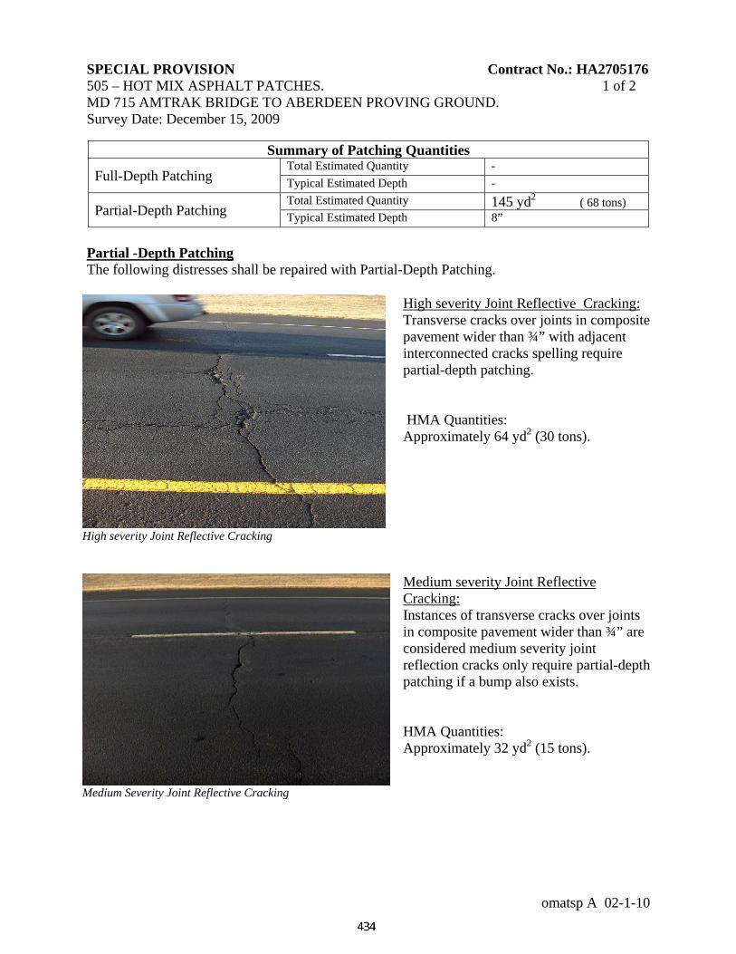
SPECIAL PROVISION Contract No.: HA2705176 505 – HOT MIX ASPHALT PATCHES. 1 of 2 MD 715 AMTRAK BRIDGE TO ABERDEEN PROVING GROUND. Survey Date: December 15, 2009
omatsp A 02-1-10
Summary of Patching Quantities
Full-Depth Patching Total Estimated Quantity - Typical Estimated Depth -
Partial-Depth Patching Total Estimated Quantity 145 yd2 ( 68 tons) Typical Estimated Depth 8”
Partial -Depth Patching The following distresses shall be repaired with Partial-Depth Patching.
High severity Joint Reflective Cracking: Transverse cracks over joints in composite pavement wider than ¾” with adjacent interconnected cracks spelling require partial-depth patching. HMA Quantities: Approximately 64 yd2 (30 tons).
High severity Joint Reflective Cracking
Medium severity Joint Reflective Cracking: Instances of transverse cracks over joints in composite pavement wider than ¾” are considered medium severity joint reflection cracks only require partial-depth patching if a bump also exists. HMA Quantities: Approximately 32 yd2 (15 tons).
Medium Severity Joint Reflective Cracking
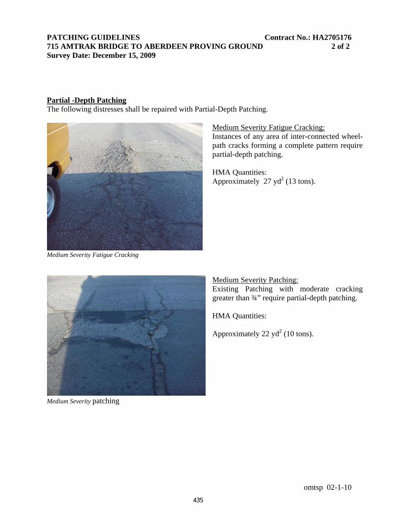
PATCHING GUIDELINES Contract No.: HA2705176 715 AMTRAK BRIDGE TO ABERDEEN PROVING GROUND 2 of 2 Survey Date: December 15, 2009
omtsp 02-1-10
Partial -Depth Patching The following distresses shall be repaired with Partial-Depth Patching.
Medium Severity Fatigue Cracking: Instances of any area of inter-connected wheel-path cracks forming a complete pattern require partial-depth patching. HMA Quantities: Approximately 27 yd2 (13 tons).
Medium Severity Fatigue Cracking
Medium Severity Patching: Existing Patching with moderate cracking greater than ¾” require partial-depth patching. HMA Quantities: Approximately 22 yd2 (10 tons).
Medium Severity patching
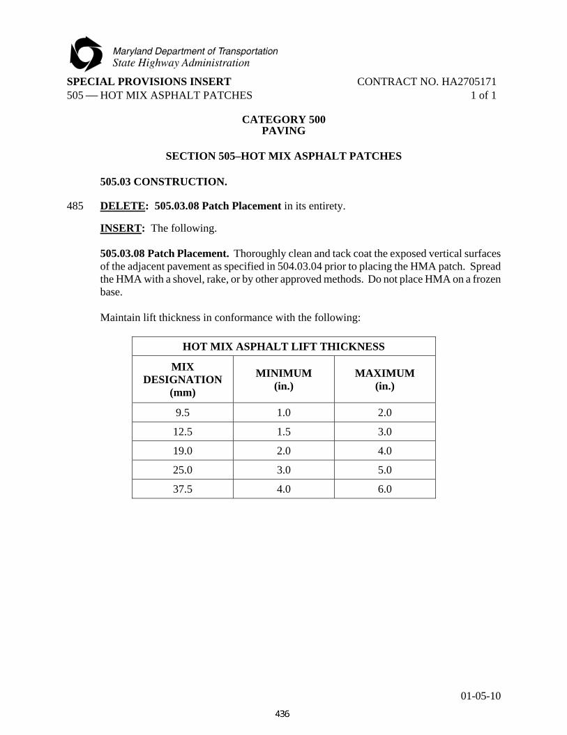
SPECIAL PROVISIONS INSERT CONTRACT NO. HA2705171 505 ⎯ HOT MIX ASPHALT PATCHES 1 of 1
01-05-10
CATEGORY 500 PAVING
SECTION 505–HOT MIX ASPHALT PATCHES
505.03 CONSTRUCTION.
485 DELETE: 505.03.08 Patch Placement in its entirety. INSERT: The following. 505.03.08 Patch Placement. Thoroughly clean and tack coat the exposed vertical surfaces of the adjacent pavement as specified in 504.03.04 prior to placing the HMA patch. Spread the HMA with a shovel, rake, or by other approved methods. Do not place HMA on a frozen base. Maintain lift thickness in conformance with the following:
HOT MIX ASPHALT LIFT THICKNESS
MIX DESIGNATION
(mm)
MINIMUM (in.)
MAXIMUM (in.)
9.5 1.0 2.0
12.5 1.5 3.0
19.0 2.0 4.0
25.0 3.0 5.0
37.5 4.0 6.0

SPECIAL PROVISIONS INSERT CONTRACT NO. HA2705171 506 – GAP GRADED STONE MIX ASPHALT 1 of 4
10-31-08
CATEGORY 500 PAVING
486 DELETE: SECTION 506 — HOT MIX ASPHALT GAP-GRADED in its entirety.
INSERT: The following.
SECTION 506 — GAP-GRADED STONE MATRIX ASPHALT
506.01 DESCRIPTION. Place gap-graded stone matrix asphalt surface (GGSMA) as specified. GGSMA shall conform to Section 504, except as specified herein.
506.02 MATERIALS.
Gap-Graded Stone Matrix Asphalt 904.05 Production Plant 915
506.03 CONSTRUCTION. 506.03.01 Demonstration. Before proceeding with the actual work, the Contractor shall demonstrate to the Engineer that a satisfactory mix can be produced, placed, and the compactive effort determined. A minimum of 100 tons of GGSMA shall be placed outside the project limits for the demonstration. A new strip will be required if a project carries over to a new season. Paver and rollers shall conform to 504.03.01. A material transfer vehicle may be used as part of the demonstration strip. 506.03.02 Hauling Units. Dry soap powder, as approved by the Engineer, may be used with the release agent specified in 915.02(f). Truck beds shall be raised to drain excess water before being loaded with GGSMA. A light dusting of No. 10 aggregate coated with 1 percent asphalt may be used in lieu of the liquid release agent.
The time between plant mixing and shipment shall not exceed one hour (storage time may vary depending upon gradation, type of binder and/or stabilizer. Storage material shall consistently have results of no less quality than mixtures discharged directly into hauling vehicles). Each load shall be completely covered with a full tarp extending a minimum of 6 in. over each side of the truck body and securely fastened.
506.03.03 Weather Restrictions. Placement of GGSMA will be permitted only when the ambient and surface temperatures are at least 50 F and in accordance with 504.03.02. 506.03.04 Material Transfer Vehicle (MTV). Use a material transfer vehicle to apply the final surface course. The MTV shall perform additional mixing of the Gap-Graded SMA material and then deposit the mixture into the paver at a uniform temperature and consistency.

SPECIAL PROVISIONS INSERT CONTRACT NO. HA2705171 506 – GAP GRADED STONE MIX ASPHALT 2 of 4
10-31-08
506.03.05 Mix Temperature. The minimum temperature of the mixture at the time of placement shall be established during the mix design procedure. 506.03.06 Pavement Thickness. The thickness of the pavement shall be as specified in the Contract Documents. Thin Lift specification 504.03.12 is not applicable to GGSMA. 506.03.07 Tack Coat. Refer to 504.03.04 except that, the resulting coating shall be residual asphalt applied at a rate of 0.03 to 0.05 gal/yd2. 506.03.08 Compaction. Compaction shall be performed using a minimum of three steel-wheeled rollers, each weighing 10 to12 tons. The rollers shall follow the paver within 500 ft. or roll as approved in the QC Plan. Rolling shall start immediately after placement. In place density shall conform to 504.03.11 (c), except that the density shall be 94 to 97 percent of maximum density. Sampling and testing shall be performed as specified in 504.03.11. The rollers shall be equipped with a watering or soapy watering system that prevents material from sticking to the rollers. 506.03.09 Control Strip. The Contractor may opt to construct a control strip for guidance in determining roller patterns to achieve optimum density. When a control strip is constructed, it shall be placed on the first workday in which SMA is placed and shall be between 400 and 500 ft in length. Based on the Contractor's evaluation of the initial control strip, paving may continue at the Contractor's risk. The Contractor will not be assessed a density pay adjustment for the amount of material required for construction of the control strips. Should the removal of any control strip be necessary, the Contractor shall remove it at no additional cost to the Administration. The Engineer may require the Contractor to construct a control strip any time during placement of SMA based on the evaluation of compaction results. 506.03.10 Pavement Profile. Refer to the Pavement Surface Profile requirements specified in the Contract Documents. 506.03.11 Sampling and Testing for Density and Mixture. For sampling and testing for density and mixture refer to 504.03.10 and 11. 506.04 MEASUREMENT AND PAYMENT. Gap-Graded Stone Matrix Asphalt will be measured and paid for at the Contract unit price per ton, complete and in place. The payment will be full compensation for furnishing, hauling, placing all materials, material transfer vehicle, antistripping additive, tack coat, control strips, setting of lines and guides where specified, and for all material, labor, equipment, tools, and incidentals necessary to complete the work. Material produced for the demonstration will not be measured but the cost will be incidental to the item GGSMA.

SPECIAL PROVISIONS INSERT CONTRACT NO. HA2705171 506 – GAP GRADED STONE MIX ASPHALT 3 of 4
10-31-08
506.04.01 Price Adjustment for Stone Matrix Asphalt Mixture and Pavement Density. Refer to 504.04 except as follows:
GAP GRADED STONE MATRIX ASPHALT MIXES
PERCENT OF MAXIMUM DENSITY
LOT AVERAGE MINIMUM (%)
NO INDIVIDUAL SUBLOT BELOW (%)
PAY FACTOR (%)
95.0 95.0 105.0 94.9 94.8 104.5 94.8 94.6 104.0 94.7 94.4 103.5 94.6 94.2 103.0 94.5 94.0 102.5 94.4 93.8 102.0 94.3 93.6 101.5 94.2 93.4 101.0 94.1 93.2 100.5 94.0 93.0 100.0 93.8 92.7 99.0 93.6 92.4 98.0 93.4 92.1 97.0 93.2 91.8 96.0 93.0 91.5 95.0 92.8 91.2 94.0 92.6 90.9 93.0 92.4 90.6 92.0 92.2 90.3 91.0 92.0 90.0 90.0 91.8 89.7 89.0 91.6 89.4 88.0 91.4 89.1 87.0 91.2 88.8 86.0 91.0 88.5 85.0
Less than 91.0 — 75.0 or rejected per Engineer
Note 1: When any test data is above 97.0, the lot may be rejected per the Engineer. When not rejected, the lot will receive a pay adjustment in accordance with the following:
(a) When the density lot average is above 97.5, the pay factor = 75%. (b) When 3 sublot densities are above 97.0, the pay factor = 95%. (c) When 4 or more sublot densities are above 97.5, the pay factor = 75%.

SPECIAL PROVISIONS INSERT CONTRACT NO. HA2705171 506 – GAP GRADED STONE MIX ASPHALT 4 of 4
10-31-08
Note 2: Pay incentive or pay disincentive will not be paid for placements identified as wedge/level courses or thin lift courses.
Note 3: When the Contractor's core specific gravity data does not compare with the Administration's core specific gravity data, only the Administration's single sublot values and lot average value will be used in acceptance decision.
Note 4: The average sublot values and the lot average will be used in acceptance decision.
506.04.02 Dispute Resolution. Refer to 915.02.01, Responsibilities of the Administration, (e).

SPECIAL PROVISIONS INSERT CONTRACT NO. HA2705171 520 — PLAIN AND REINFORCED PORTLAND CEMENT CONCRETE PAVEMENTS 1 of 2
10-31-08
CATEGORY 500
PAVING
SECTION 520 — PLAIN AND REINFORCED PORTLAND CEMENT CONCRETE PAVEMENTS
520.03 CONSTRUCTION.
506 ADD: The following after 520.03.16.
520.03.17 Dowel Bar Placement Checks. After the placement of the PCC pavement is complete and cured, the alignment and placement of the dowel bars will be checked by the Administration using a non-destructive test method. A random representative sample of joints will be tested to determine conformance with the following:
(a) Vertical Skew. The vertical skew shall be no greater than 1/2 in. tolerance over a
12 in. length of dowel bar. (b) Horizontal Skew. The horizontal skew shall be no greater than 1/2 in. tolerance
over a 12 in. length of dowel bar. (c) Depth of Dowel Bar. The dowel bar shall be located within the middle third of the
slab thickness. (d) Joint. The joint saw cut shall be in the middle third of the dowel bar length. When a dowel bar is tested and does not conform to all of the above, it is then in non-
conformance or misaligned. After testing is complete, the percentage of those dowel bars not meeting the above will be determined. Deficiency will be subject to a reduced payment as specified in 520.04. This is in addition to the reduced pay for slab thickness.
520.04 MEASUREMENT AND PAYMENT. 506 ADD: The following after 520.04.01.
520.04.02 Dowel Bar Misalignment Price Adjustment. Payment for the percentage of dowel bars accepted at a reduced price for not conforming to the proper alignment will be adjusted by the factors shown in the following table. Alignment is determined by procedures specified in 520.03.17. This shall be a reduced price for the portland cement concrete pavement item in addition to any reduction due to pavement thickness.

SPECIAL PROVISIONS INSERT CONTRACT NO. HA2705171 520 — PLAIN AND REINFORCED PORTLAND CEMENT CONCRETE PAVEMENTS 2 of 2
10-31-08
DOWEL BAR PRICE ADJUSTMENT
Percent of Misaligned Dowel Bars *
Percent of Payment, Contract Unit Price **
0.0 to 30.0 100 30.1 to 40.0 90 40.1 to 50.0 80
Greater than 50.0
Corrective action or pay reduction as determined by
the Engineer
*This is the percentage of all dowel bars tested. **This price adjustment is to the PCC price and not for the dowel bars. This is in addition to
any price adjustment for pavement thickness.

SPECIAL PROVISIONS INSERT CONTRACT NO. HA2705171 522 — PORTLAND CEMENT CONCRETE PAVEMENT REPAIRS 1 of 1
10-31-08
CATEGORY 500 PAVING
SECTION 522 — PORTLAND CEMENT CONCRETE PAVEMENT REPAIRS 522.02 MATERIALS.
509 DELETE: 522.02 MATERIALS in its entirety.
INSERT: The following:
522.02 MATERIALS. Refer to 520.02 except as follows:
Graded Aggregate for Base Course 901.01 Crusher Run Aggregate CR-6 901.01 Concrete Mix No. 9 902.10 Nonshrink Grout 902.11(c) Epoxy Grout 902.11(d) Epoxy Adhesive 921.04
522.02.01 Polyester Grout. A polyester grout may be used in lieu of epoxy grout, provided the grout conforms to 902.11(d). Identify cartridge type systems by batch or lot number.
522.02.02 Epoxy Adhesives. Refer to 921.04. Use water insensitive materials classified as Type IV, Grade 3, Class B and C.
522.02.03 Reinforcement. Section 908 for reinforcement, including load transfer assemblies, tie bars, deformed steel bars, and longitudinal tie devices, except all material shall be epoxy coated.

SPECIAL PROVISIONS CONTRACT NO. HA2705171 550 ⎯ PAVEMENT MARKING PAINT 1 of 2
10-31-08¶
CATEGORY 500 PAVING
SECTION 550 ⎯ PAVEMENT MARKING PAINT
550.01 DESCRIPTION. Furnish and apply nontoxic lead free waterborne pavement marking paint to pavement surfaces as specified in the Contract Documents or as directed by the Engineer. These markings includes lines (striping), legends (letters and numbers) and symbols. 550.02 MATERIALS. Paint is a nontoxic lead free waterborne pavement marking and is a non-durable material. All Paint Pavement Marking material shall be selected from the Qualified Products List. Nontoxic Lead Free Waterborne Pavement Marking Material 951.01 550.03 CONSTRUCTION. 550.03.01 Quality Control / Quality Assurance. Refer to Section 549. 550.03.02 Application. The location, width, and type of marking shall be as specified in the Contract Documents or as directed by the Engineer. (a) Temperature. The markings shall be applied when the paint, ambient and surface
temperature, and relative humidity conform to the manufacturer’s recommendations.
(b) Glass Beads. The Contractor shall apply the Maryland Blend gradation of glass beads uniformly across the surface of the stripe, at the rate of 7 to 9 lb/gal of paints.
(c) Thickness. The paint shall be applied at a wet film thickness of 18 ± 1 mils. (d) Color. The color of the dry markings shall match Federal Standard 595 (38907 - yellow or
37925 - white). The Contractor shall make available the specified color chips for the Engineer’s use to visually determine that the waterborne material matches the specified color.
(e) No-Track. The paint shall conform to 60 second no-track requirements. The no-track
condition shall be determined by passing over the applied line at approximately 30 degrees with a standard passenger car or pickup truck. When viewed from a distance of 50 ft, the pavement surface shall show no evidence of the paint being picked up and redeposited on the pavement by the vehicle.
(f) Retroreflectance. The minimum retroreflectance shall be 150 millicandelas/lux/square
meter for yellow and 250 millicandelas/lux/square meter for white as determined in conformance with MSMT 729.

SPECIAL PROVISIONS CONTRACT NO. HA2705171 550 ⎯ PAVEMENT MARKING PAINT 2 of 2
10-31-08¶
550.03.03 Application Equipment. The equipment used for application of the paint shall be approved by the Engineer prior to start of work, and shall be capable of applying waterborne traffic paint that has been approved by the Administration. The Contractor shall provide access to the paint application equipment for inspection by the Engineer. The paint carriage on the left side of the paint truck shall have three paint and bead guns. The paint carriage on the right side of the paint truck shall have two paint and bead guns.
All 10 in. lines shall be applied using two paint and bead guns. Raising the paint carriage in order to paint these lines with one paint gun and bead gun is prohibited. The footage counters used to measure pavement markings shall be calibrated, and a notarized certification shall be submitted to the Engineer as part of the Quality Control Plan. Temperature gauges shall be calibrated every six months and a copy of the calibration certification shall be submitted to the Engineer as part of the Quality Control Plan. The applicator shall apply the surface dressing beads to the wet paint marking by means of a pressurized bead dispenser or other mechanical conveying method not dependent upon gravity for uniform application. The bead dispenser shall be equipped with an automatic cutoff system that will stop the flow of the paint material whenever there is a disruption in the application of the beads so that all markings placed shall be covered with a uniform layer of surface dressing beads. Application equipment shall be capable of applying the markings at multiple width settings ranging from 4 to 12 in. The applicator shall provide a method for cleanly cutting off stripe ends and shall be capable of applying all longitudinal pavement markings. The equipment shall be mobile and maneuverable to the extent that straight lines can be followed and all standard curves can be made in true arcs. All parts of the equipment shall be thoroughly cleaned of foreign material or different colored material prior to the introduction of a new batch of material. 550.04 MEASUREMENT AND PAYMENT. The payment will be full compensation for all pavement preparation, furnishing and placing of markings, testing, and for all material, labor, equipment, tools, and incidentals necessary to complete the work. Refer to 549.04. Pavement Marking Paint will be measured and paid for at the Contract unit price for one or more of the following items:
(a) Pavement Marking Paint lines (striping) will be measured and paid for at the Contract unit price per linear foot for the color and width specified.
(b) Pavement Marking Paint Legends (letters and numbers) and Symbols will be measured and paid for at the Contract unit price per square foot. The square foot pay quantity for Legends (letters and numbers) and Symbols will be as specified in the Administrations Standard Details.

SPECIAL PROVISIONS CONTRACT NO. HA2705171 552 — PAVEMENT MARKING EPOXY 1 of 2
10-31-08¶
CATEGORY 500 PAVING
SECTION 552 — EPOXY PAVEMENT MARKING
552.01 DESCRIPTION. Furnish and apply lead-free two component epoxy white or yellow pavement markings with large and standard glass beads. The locations and patterns shall be as specified in the Contract Documents or as directed by the Engineer. 552.02 MATERIALS.
Lead Free Two Component Epoxy Pavement Marking Materials 951.08
Epoxy is a durable pavement marking material. 552.03 CONSTRUCTION. 552.03.01 Quality Assurance/Quality Control. Refer to Section 549. 552.03.02 Application. The location, width, and type of marking, shall be as specified in the Contract Documents or as directed by the Engineer. Placing pavement marking material over longitudinal joints is prohibited; they shall be offset 2 in. or as directed by the Engineer. Epoxy pavement markings shall conform to the following:
(a) Temperature. The markings shall be applied when the epoxy, ambient, and surface temperatures, and the relative humidity conform to the manufacturer’s recommendations.
(b) Thickness. The epoxy pavement marking material shall be applied at a thickness of
20 ± 1 mils.
(c) Glass Beads. The Contractor shall apply a double-drop of large and standard glass beads uniformly across the surface of the stripe, at the rate of 11 to 13 lb/gal with a maximum total application of 25 lb/gal. The bead guns shall be calibrated in conformance with MSMT 729.
(d) Color. The color of the dry markings shall match Federal Standard 595 (13538 - yellow or
17886 - white). The Contractor shall make available the specified color chips for the Engineer’s use to visually determine that the epoxy material matches the specified color.
(e) Retroreflectance. The minimum retroreflectance shall be 200 millicandelas/lux/square
meter for yellow and 275 millicandelas/lux/square meter for white as determined in conformance with MSMT 729.
SPECIAL PROVISIONS CONTRACT NO. HA2705171 552 — PAVEMENT MARKING EPOXY 2 of 2
10-31-08¶
552.03.03 Application Equipment. The equipment used for application of the epoxy shall be approved by the Engineer prior to start of work, and shall be capable of applying material that has been approved by the Administration. The Contractor shall provide access to the application equipment for inspection by the Engineer. The gun carriage on the left side of the striping truck shall have three epoxy and bead guns. The gun carriage on the right side of the truck shall have two epoxy and bead guns. All 10 in. lines shall be applied using two epoxy and bead guns. Raising the gun carriage in order to stripe these lines with one epoxy gun and one bead gun is prohibited. The footage counters used to measure pavement markings shall be calibrated and a notarized certification shall be submitted to the Engineer prior to application as part of the Quality Control Plan. Temperature gauges shall be calibrated every six months and a copy of the calibration certification shall be submitted to the Engineer, as part of the Quality Control Plan. The applicator shall apply the surface dressing beads to the epoxy marking by means of a pressurized bead dispenser or other mechanical conveying method not dependent upon gravity for uniform application. The bead dispenser shall be equipped with an automatic cutoff system that will stop the flow of the epoxy material whenever there is a disruption in the application of the beads so that all markings placed shall be covered with a uniform layer of surface dressing beads. Application equipment shall be capable of applying the markings at multiple width settings ranging from 4 to 12 in. as specified in the Contract Documents. The applicator shall provide a method for cleanly cutting off stripe ends and shall be capable of applying all longitudinal pavement markings. The equipment shall be mobile and maneuverable to the extent that straight lines can be followed and all standard curves can be made in true arcs. All parts of the equipment shall be thoroughly cleaned of foreign material or different colored material prior to the introduction of a new batch of material. Testing performed by the Administration will provide the basis for final acceptance. 552.04 MEASUREMENT AND PAYMENT. Epoxy Pavement Marking will be measured and paid for at the Contract unit price per linear foot for the color and width specified. The payment will be full compensation for all pavement preparation, furnishing and placing of markings, testing, and for all material, labor, equipment, tools, and incidentals necessary to complete the work.
SPECIAL PROVISIONS CONTRACT NO. HA2705171 553 — LEAD FREE THERMOPLASTIC MARKINGS 1 of 3
10-31-08¶
CATEGORY 500 PAVING
SECTION 553 — LEAD FREE REFLECTIVE THERMOPLASTIC
PAVEMENT MARKINGS 553.01 DESCRIPTION. Prepare and apply lead free reflective thermoplastic pavement markings to roadway surfaces as specified in the Contract Documents or as directed by the Engineer. 553.02 MATERIALS. Lead Free Reflective Thermoplastic Pavement Markings 951.02 553.03 CONSTRUCTION. 553.03.01 Quality Assurance/Quality Control. Refer to 549.03.01. 553.03.02 Application Equipment. An oil or air jacketed kettle shall be utilized for uniform melting and heating of the thermoplastic material. The kettle shall provide continuous mixing and agitation of the material. The kettle and the applicator shall be equipped with an automatic thermostatic device to provide positive temperature control. The equipment shall be constructed so that all mixing and conveying parts, up to and including the application apparatus, maintains the material at the specified temperature. Conveying parts of the applicator between the reservoir and the application apparatus shall be constructed to prevent clogging and accumulation. The applicator shall be capable of containing a minimum of 600 lb of molten thermoplastic material. The kettle and applicator shall be constructed and arranged to conform to the requirements of the National Board of Fire Underwriters (NBFU), the National Fire Protection Association (NFPA), and State and local authorities. Temperature gauges shall be calibrated every six months and a copy of the calibration certification shall be submitted to the Engineer. The applicator shall apply the surface dressing beads to the molten thermoplastic marking by means of a pressurized bead dispenser or other mechanical conveying method not dependent upon gravity for uniform application. The bead dispenser shall be equipped with an automatic cutoff system that will stop the flow of the thermoplastic material whenever there is a disruption in the application of the beads so that all markings placed shall be covered with a uniform layer of surface dressing beads. Application equipment shall be capable of applying the markings at multiple width settings ranging from 4 to 12 in. as specified in the Contract Documents. The applicator shall provide a method for cleanly cutting off stripe ends and shall be capable of applying all longitudinal pavement markings. The equipment shall be mobile and maneuverable to the extent that straight lines can be followed and all standard curves can be made in true arcs.

SPECIAL PROVISIONS CONTRACT NO. HA2705171 553 — LEAD FREE THERMOPLASTIC MARKINGS 2 of 3
10-31-08¶
All parts of the equipment shall be thoroughly cleaned of foreign material or different colored material prior to the introduction of a new batch of thermoplastic material. 553.03.03 Cleaning Pavement Surfaces. Refer to 549.03.02. 553.03.04 Application. The ambient and surface temperatures shall be at least 50 F and rising at the time of application. Thermoplastic pavement markings shall be sprayed onto the pavement surface. Only the spray method of application shall be permitted. Gore areas, crosswalks, small intersections, roundabouts, and other areas which preclude the application of the markings with truck mounted equipment will be exempt from the spray application requirement. Thermoplastic pavement markings shall conform to the following:
(a) Temperature. The molten material temperature shall be between 400 and 440 F unless otherwise recommended by the manufacturer, and approved by the Engineer.
(b) Primer. A primer shall be used if thermoplastic is applied to portland cement concrete.
Any primer used shall be compatible with the thermoplastic material. (c) Thickness. The pavement markings shall yield a solid thickness range of 80 to 95 mils
above the roadway surface across the middle two-thirds of the line width when tested as specified in MSMT 729. Variation from this range will be used for the price adjustment specified in 553.04.01.
(d) Glass Beads. Glass beads shall be uniformly applied to the surface of the molten
thermoplastic at the minimum rate of 7 to 9 lb/100 ft2, as specified in MSMT 729. (e) Color. The color of the dry markings shall match Federal Standard 595 (13538 - yellow or
17886 - white). The Contractor shall supply the specified color chips for the Engineer’s use to visually determine that the thermoplastic material matches the specified color.
(f) Retroreflectance. Refer to MSMT 729. The millicandellas/lux/square meter values taken
anytime within the first 30 days shall conform to the following:
RETROREFLECTANCE
COLOR RETROREFLECTIVITY CORRECTIVE ACTION
White equal to or greater than 250 None
Yellow equal to or greater than 150
White less than 250 Necessary corrective actions, including grinding if necessary,
and re-tracing Yellow less than 150
(g) Width. Refer to 549.03.01(a). (h) Alignment. Refer to 549.03.01(a).

SPECIAL PROVISIONS CONTRACT NO. HA2705171 553 — LEAD FREE THERMOPLASTIC MARKINGS 3 of 3
10-31-08¶
(i) Layout Markings. Refer to 549.03.01(a). 553.03.05 Quality Control Test Strip. Refer to 549.03.03. 553.03.06 Responsibility. Refer to Section 549. 553.03.07 Observation Period. Refer to Section 549.03.06. 553.04 MEASUREMENT AND PAYMENT. Refer to 549.04. The reflectometer will become the property of the Contractor at the completion of the project. 553.04.01 Price Adjustment for Film Thickness. The unit price for Lead Free Reflective Thermoplastic Pavement Markings will be per striped linear foot based on MSMT 729 calculations for thickness, and will be adjusted in conformance with the following:
MIL THICKNESS PERCENT OF PAYMENT - UNIT PRICE
80 – 95 (a)(b) 100
75 – 79 90
70 – 74 88
65 – 69 82
60 – 64 72
Less than 60 Retrace to achieve a thickness of 80 to 95 mils. Retrace thickness shall be 30 mils min (b).
(a) The Engineer may require the Contractor to remove excess material thickness. (b) Removal of excess material and retracing pavement markings shall be performed at
no additional cost to the Administration.

SPECIAL PROVISIONS CONTRACT NO. HA2705171 556 — PREFORMED THERMOPLASTIC PAVEMENT MARKINGS 1 of 2
10-31-08¶
CATEGORY 500 PAVING
SECTION 556 — PREFORMED THERMOPLASTIC PAVEMENT MARKINGS
556.01 DESCRIPTION. Furnish and install heat applied preformed thermoplastic pavement marking symbols, legends, and lines as specified in the Contract Documents or as directed by the Engineer. 556.02 MATERIALS. Preformed Thermoplastic is a durable pavement marking material. All Preformed Thermoplastic Pavement Marking material shall be selected from the Qualified Products List. Heat Applied Permanent Preformed Thermoplastic Pavement Marking Material 951.06 556.03 CONSTRUCTION. 556.03.01 Quality Assurance/Quality Control. Refer to 549. 556.03.02 Application. The location, width, and type of marking, shall be as specified in the Contract Documents or as directed by the Engineer. Applying pavement markings over longitudinal joints is prohibited; they shall preferably be offset 2 in. from them.
Thermoplastic Pavement Marking shall conform to the following: (a) Temperature. The markings shall be applied when the thermoplastic, ambient, and
surface temperature, and relative humidity conform to the manufacturer’s recommendations.
(b) Color. The color of the dry markings shall match Federal Standard 595 (13538 - yellow or
17886 - white). The Contractor shall supply the specified color chips for the Engineer’s use to visually determine that the thermoplastic material matches the specified color.
(c) Primer. When specified by the manufacturer, a primer shall be used if thermoplastic is
applied to Portland cement concrete.
(d) Retroreflectance. The minimum retroreflectance shall be 150 millicandelas/lux/square meter for yellow and 250 millicandelas/lux/square meter for white as determined in conformance with MSMT 729.

SPECIAL PROVISIONS CONTRACT NO. HA2705171 556 — PREFORMED THERMOPLASTIC PAVEMENT MARKINGS 2 of 2
10-31-08¶
556.03.05 Packaging. The material shall be handled for shipping, unloading and storage as recommended by the manufacturer. Each shipping package shall be marked with the following information: (a) Manufacturer's name. (b) Description of item. (c) Date of manufacture. (d) Contractor's name. (e) Purchase order number. (f) Lot number. (g) Color. 556.04 MEASUREMENT AND PAYMENT. The payment will be full compensation for all pavement preparation, furnishing and placing of markings, testing, and for all material, labor, equipment, tools, and incidentals necessary to complete the work. Preformed Thermoplastic Pavement Marking Legends (letters and numbers) and Symbols will be measured and paid for at the Contract unit price per square foot. The square foot pay quantity for Legends (letters and numbers) and Symbols will be as specified in the Administrations Standard Details Preformed Thermoplastic Pavement Marking lines will be measured and paid for at the Contract unit price per linear foot for the color and width specified.

SPECIAL PROVISIONS CONTRACT NO. HA2705171 557 — SNOWPLOWABLE RAISED PAVEMENT MARKERS 1 of 3
10-31-08¶
CATEGORY 500 PAVING
SECTION 557 – SNOWPLOWABLE RAISED PAVEMENT MARKERS
557.01 DESCRIPTION. Furnish and install new Snowplowable Raised Pavement Markers (SRPM) and replacement components as specified in the Contract Documents or as directed by the Engineer. 557.02 MATERIALS. Castings Qualified Products List / 951.05 Pavement Marker Reflector Lenses Qualified Products List / 951.05 Epoxy 951.05 Snowplowable Raised Pavement Markers are durable materials. 557.03 CONSTRUCTION. Casting. Recycled iron castings are prohibited. Placement. Snowplowable Raised Pavement Markers shall be installed and located as specified in the Contract Documents and in conformance with the Maryland Manual of Uniform Traffic Control Devices (MdMUTCD). General Installation Requirements.
(a) The Contractor shall install the SRPM no later than two weeks after the completion of the final surface or as directed by the Engineer.
(b) At the time of installation, the road surface and ambient temperature shall be as specified in
the manufacturers’ recommendations. Installing markers on wet pavement surfaces as determined in MSMT 729 is prohibited.
(c) At the time of installation, the Contractor shall have on the jobsite all the materials
necessary to complete the installation.
(d) The quality control test strip containing a minimum of 10 groove cuts spaced as specified in the Contract Document shall be constructed to verify the accuracy and ability of the equipment and personnel. The contractor shall replace at no additional cost to the Administration any incorrect groove cuts and any incorrect casting placements within the test strip.
(e) At the time of installation, SRPM castings delivered with Pavement Marker Reflector Lens
affixed should be free of dirt, dust, oil, grease, rust, moisture, or any foreign matter that will impair adhesion to the pavement. Any residual material that inhibits retroreflectivity of the reflector lens shall be removed without damage to the lens surface. It shall be the contractor’s responsibility to clean each contaminated casting by sand blasting, wire brushing or other procedure approved by the Engineer to remove all foreign matter prior to installation. The use of chemicals to remove rust from the castings is prohibited.

SPECIAL PROVISIONS CONTRACT NO. HA2705171 557 — SNOWPLOWABLE RAISED PAVEMENT MARKERS 2 of 3
10-31-08¶
(f) The contractor shall replace at no additional cost to the Administration any incorrect groove cut and any incorrect casting placement. An additional test strip may be required by the Engineer in the event of incorrect installations. Incorrect installations, as determined by the Engineer, shall be corrected and repaired by the contractor at no additional cost to the Administration.
Pavement Marker Reflector Lens. Reflector lenses for pavement markers shall be the same color as the adjacent pavement marking except the back side shall be as follows;
(a) One-Way Applications: The backside for One-Way Markers shall be red or blank as specified in the Contract Documents or as directed by the Engineer.
(b) Two-Way Applications: The backside for Two-Way Markers shall be the same color as the
adjacent pavement marking.
The pavement marker reflector lens shall be imprinted with the model/batch number and the manufacturers’ name.
Castings. The casting shall be imprinted with the model number and the manufacturer's name. New Installation.
(a) The SRPM shall be installed in accordance with manufacturer’s recommendations and D 4383. The installed height shall not exceed 0.25 in. above the road surface. The surface of the keel and web shall be free of scale, dirt, oil, grease or any other contaminant which may reduce its bond to the epoxy adhesive. All requirements of the manufacturer’s installation instructions shall be met.
(b) The groove cut for the casting shall be the appropriate dimensions to allow 0.125 in.
movement side to side of the casting. All leveling lugs on the casting must contact the pavement. The leading and trailing edges of the casting must lie below the pavement surface and the casting properly seated. All other requirements of the manufacturer’s installation instructions shall be met.
(c) Lenses used shall be of a type specifically manufactured and approved for use as SRPM
reflector lenses. Lenses that are manufactured exclusively for recessed pavement markers are not permitted as substitutes for SRPM reflector lenses.
Replacement.
(a) Casting Replacement. The re-use of damaged or removed castings is prohibited.
(b) Pavement Marker Reflector Lens Replacement. The Contractor shall remove and dispose of any damaged reflector lens and replace with a new lens. Previously installed undamaged castings which are missing a reflector lens shall have a new reflector lens installed. The replacement lenses shall be installed per manufacturer’s written instructions.
(c) Casting Groove Cut Replacement and Accuracy. The re-use of existing groove cuts is
prohibited; castings shall only be installed in new groove cuts. Previously used groove cuts shall be permanently patched in accordance with applicable sections of 504, 505 and 522 or

SPECIAL PROVISIONS CONTRACT NO. HA2705171 557 — SNOWPLOWABLE RAISED PAVEMENT MARKERS 3 of 3
10-31-08¶
as directed by the Engineer. The location of the replacement groove cut shall be within 10 percent longitudinally in front (with the direction of traffic) and no lateral deviation exceeding 1-1/2 in.
Casting Adhesive. The epoxy adhesive used to fasten the castings to the pavement surface shall conform to D 4383-05 Table X1.1. Reflector Lens Adhesive in Casting. The adhesive used to fasten the reflector lens to the casting shall meet the manufacturers’ recommendations. Quality Assurance/Quality Control. Section 549. Observation Period. The Contractor shall replace at no additional cost to the Administration, any SRPM or Pavement Marker Reflector Lenses found to be damaged, non-retroreflective or missing due to improper installation or manufacturing defects within 180 days after opening to traffic. 557.04 MEASUREMENT AND PAYMENT. The payment will be full compensation for all pavement preparation, furnishing and placement of SRPM’s, testing, removal, groove cutting, repair and all materials, labor, equipment, tools and all incidentals necessary to complete the work.
(a) Snowplowable Raised Pavement Markers will be paid for at the Contract unit price per each. Furnishing and installing SRPM includes the casting, reflector, adhesive and grooving.
(b) Removal of existing Castings, excluding any incorrect installation by the Contractor, and
repair of Groove Cuts will be paid for at the Contract unit price per each.
(c) Replacement of Pavement Marker Reflector Lenses will be paid for at the Contract unit price per each.

SPECIAL PROVISIONS CONTRACT NO. HA2705171 558 — RECESSED PAVEMENT MARKERS 1 of 3
10-31-08
CATEGORY 500 PAVING
SECTION 558 – RECESSED PAVEMENT MARKERS
558.01 DESCRIPTION. Furnish and install Recessed Pavement Markers (RPM) as specified in the Contract Documents, and or as directed by the Engineer. 558.02 MATERIALS. Pavement Marker Reflector Lens Qualified Products List / 951.05 Epoxy Adhesive M237 Type II / 951.05
Recessed Pavement Markers are durable materials. 558.03 CONSTRUCTION. Placement. Recessed Pavement Markers shall be installed and located as directed by the Contract Documents and in conformance with the Maryland Manual of Uniform Traffic Control Devices (MdMUTCD). General Installation Requirements.
(a) The Contractor shall install the Recessed Pavement Markers no later than two weeks after the completion of the final surface or as directed by the Engineer.
(b) At the time of installation, the road surface and ambient temperature shall meet the
manufacturers’ recommendations for installation of the markers. Installing markers on wet pavement surfaces as determined in MSMT 729 is prohibited.
(c) At the time of installation, the Contractor shall have on the jobsite all the materials
necessary to complete the installation.
(d) A test strip containing a minimum of 10 groove cuts spaced as specified in the Contract Document shall be constructed to verify the accuracy and ability of the equipment and personnel. The contractor shall replace at no additional cost to the Administration any incorrect groove cut, including test strip cuts.
(e) At the time of installation, the Recessed Pavement Markers should be free of dirt, dust, oil,
grease, rust, moisture, or any foreign matter that will impair adhesion to the pavement. It shall be the contractor’s responsibility to clean each contaminated Recessed Pavement Marker to remove all foreign matter without damaging the reflective surface prior to installation.
Pavement Marker Reflectors. Pavement Marker Reflector lenses for pavement markers shall be the same color as the adjacent pavement marking except the back side shall be as follows;
(a) One-Way Applications: The backside for One-Way Markers shall be red or blank as specified in the Contract Documents or as directed by the Engineer.
(b) Two-Way Applications: The backside for Two-Way Markers shall be the same color as the
adjacent pavement marking.
SPECIAL PROVISIONS CONTRACT NO. HA2705171 558 — RECESSED PAVEMENT MARKERS 2 of 3
10-31-08
The pavement marker reflector lens shall be imprinted with the model/batch number and the manufacturers’ name. New Installation.
(a) Recessed Marker Reflector Lenses shall be installed in accordance with D 4383 (the top of the marker shall be 0.06 in. below the pavement surface) or as directed by the Engineer. Lenses used shall be of a type specifically manufactured and approved for use as Recessed Marker Reflector lenses. Lenses that are manufactured exclusively for Snow Plowable Raised Pavement Markers are not permitted as substitutes for recessed lenses.
(b) The groove cut for mono-directional recessed marker reflectors lenses shall be the
appropriate dimensions to properly seat one reflector lens in conformance with the manufacturer’s recommendations and D 4383.
(c) The groove cut for bi-directional recessed marker reflectors lenses shall be the appropriate
dimensions to properly seat two reflectors lenses, one on each end, in conformance with the manufacturer’s recommendations and D 4383.
Replacement.
(a) Reflector Lens Replacement. The Contractor shall remove and dispose of any damaged
reflector lens and replace with a new lens. The replacement reflector lens shall conform to the same requirements as the original reflector lens unless specified by the Contract Documents or as directed by the Engineer. The replacement lenses shall be installed per manufacturer’s recommendations.
(b) Groove Cut. Existing groove cuts may be reused when they are in compliance with D 4383.
(c) Damaged Groove Cut Repair and Accuracy. Damaged groove cuts shall be repaired in
accordance with applicable Sections of 504, 505, 522, and as directed by the Engineer. The location of the replacement groove cut shall be within one foot longitudinally in front (with the direction of traffic) and no lateral deviation exceeding 1½ in.
Assurance/Quality Control. Refer to 549. Observation Period. The Contractor shall replace at no additional cost to the Administration, any Pavement Marker Reflector Lenses found to be damaged, non-retroreflective or missing due to improper installation or manufacturing defects within 180 days after opening to traffic. 558.04 MEASUREMENT AND PAYMENT. The payment will be full compensation for all pavement preparation, furnishing and placement of pavement markers, testing, removal, groove cutting, repair and all materials, labor, equipment, tools and all incidentals necessary to complete the work.
(a) Pavement Marker Reflector Lenses will be paid for at the Contract unit price per each. Furnishing and installing the Recessed Marker includes the reflector and adhesive.
(b) Groove Cuts will be paid for at the Contract unit price per each.

SPECIAL PROVISIONS CONTRACT NO. HA2705171 558 — RECESSED PAVEMENT MARKERS 3 of 3
10-31-08
(c) Repair of damaged existing groove cuts will be paid for at the Contract unit price per each.

SPECIAL PROVISIONS CONTRACT NO. HA2705171 559 — PREFORMED PATTERNED REFLECTIVE MARKINGS 1 of 3
10-31-08¶
CATEGORY 500 PAVING
SECTION 559 — PERMANENT PREFORMED PATTERNED
REFLECTIVE PAVEMENT MARKINGS 559.01 DESCRIPTION. Furnish and apply permanent preformed patterned reflective pavement (PPPRP) markings as specified in the Contract Documents or as directed by the Engineer. 559.02 MATERIALS. Permanent Preformed Patterned Reflective Pavement Marking Materials 951.07 559.03 CONSTRUCTION. 559.03.01 General. PPPRP markings shall be applied in conformance with the manufacturer’s recommendations or as directed by the Engineer. On new hot mix asphalt projects, the PPPRP markings shall be inlaid into the hot surface of the top course of pavement. No top course paving shall be permitted unless the stripping crew and marking materials are at the project site. When the Contract Documents specifies the use of PPPRP markings on concrete pavements or existing asphalt pavements, the Contractor shall use heat, solvent, or other type of adhesive primer in conformance with the manufacturer’s recommendations. Preformed legends and symbols shall conform to the applicable shape and sizes as specified in the MdMUTCD, and Contract Documents. PPPRP markings shall conform to pavement contours and be resistant to deformation by traffic and damage from snow removal equipment. Surface preparation, use of solvents and primers and equipment used in the application of PPPRP markings shall conform with the manufacturer’s recommendations and be approved by the Engineer. After PPPRP markings are applied, they shall be immediately ready for traffic. 559.03.02 Quality Assurance/Quality Control. Refer to 549.03.01.
559.03.03 Cleaning Pavement Surfaces. Refer to 549.03.02. 553.03.04 Application. Refer to 549.03.03 and the following: (a) Manufacturer’s Recommendations. The Contractor shall provide a copy of the
manufacturer’s recommendations to the Engineer, and shall follow them for the installation of the line markings.
(b) Adherence. Adherence of PPPRP markings shall be randomly checked by using a paint
scraper or another approved tool, which shall be held nearly parallel with the highway surface, so there is no dislodging of the tape.
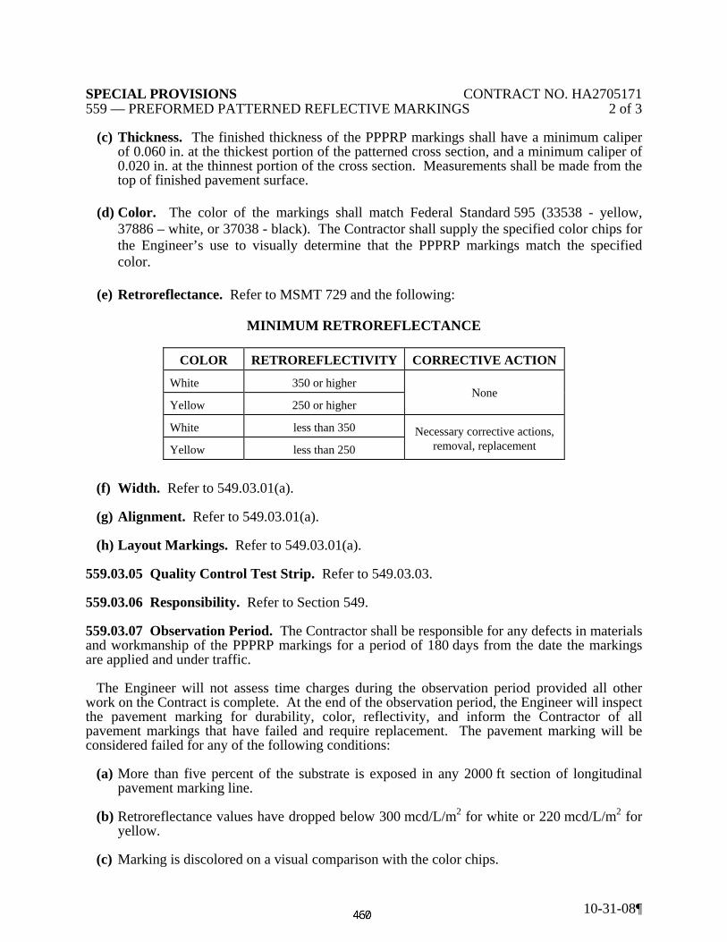
SPECIAL PROVISIONS CONTRACT NO. HA2705171 559 — PREFORMED PATTERNED REFLECTIVE MARKINGS 2 of 3
10-31-08¶
(c) Thickness. The finished thickness of the PPPRP markings shall have a minimum caliper of 0.060 in. at the thickest portion of the patterned cross section, and a minimum caliper of 0.020 in. at the thinnest portion of the cross section. Measurements shall be made from the top of finished pavement surface.
(d) Color. The color of the markings shall match Federal Standard 595 (33538 - yellow,
37886 – white, or 37038 - black). The Contractor shall supply the specified color chips for the Engineer’s use to visually determine that the PPPRP markings match the specified color.
(e) Retroreflectance. Refer to MSMT 729 and the following:
MINIMUM RETROREFLECTANCE
COLOR RETROREFLECTIVITY CORRECTIVE ACTION
White 350 or higher None
Yellow 250 or higher
White less than 350 Necessary corrective actions, removal, replacement Yellow less than 250
(f) Width. Refer to 549.03.01(a). (g) Alignment. Refer to 549.03.01(a). (h) Layout Markings. Refer to 549.03.01(a). 559.03.05 Quality Control Test Strip. Refer to 549.03.03. 559.03.06 Responsibility. Refer to Section 549. 559.03.07 Observation Period. The Contractor shall be responsible for any defects in materials and workmanship of the PPPRP markings for a period of 180 days from the date the markings are applied and under traffic. The Engineer will not assess time charges during the observation period provided all other work on the Contract is complete. At the end of the observation period, the Engineer will inspect the pavement marking for durability, color, reflectivity, and inform the Contractor of all pavement markings that have failed and require replacement. The pavement marking will be considered failed for any of the following conditions: (a) More than five percent of the substrate is exposed in any 2000 ft section of longitudinal
pavement marking line. (b) Retroreflectance values have dropped below 300 mcd/L/m2 for white or 220 mcd/L/m2 for
yellow. (c) Marking is discolored on a visual comparison with the color chips.

SPECIAL PROVISIONS CONTRACT NO. HA2705171 559 — PREFORMED PATTERNED REFLECTIVE MARKINGS 3 of 3
10-31-08¶
The Contractor shall remove and replace all failed PPPRP markings within 30 days of receiving written notification from the Engineer at no additional cost to the Administration. Work shall be in conformance with the manufacturer’s recommendation and as approved by the Engineer before the project is accepted. The replacement markings shall conform to the same requirements as the original markings. If the work is not completed in this period, the Engineer will resume time charges until this work is completed. At the end of the observation period, the Engineer will accept the work and terminate the Contractor’s responsibilities upon satisfactory inspection of the PPPRP markings. 559.04 MEASUREMENT AND PAYMENT. Measurement and payment for the pertinent Permanent Preformed Patterned Reflective Pavement Marking items will be as specified in 549.04. The reflectometer will become the property of the Contractor at the completion of the project.

SPECIAL PROVISIONS CONTRACT NO.HA2705171 565 — REMOVAL OF EXISITNG PAVEMENT MARKINGS 1 of 2
10-31-08
CATEGORY 500 PAVING
SECTION 565 — REMOVAL OF EXISTING PAVEMENT MARKINGS
565.01 DESCRIPTION. Remove existing pavement markings (lines, letters, numbers, arrows, and symbols) during temporary or permanent traffic shifts, and repairing any roadway areas damaged during the removal process. This Specification does not apply to raised or recessed pavement markers. Temporary blackout tape shall be applied when existing pavement markings will require salvaging for reuse after completion of temporary traffic shifts necessary to perform work specified in the Contract Documents. Refer to 104.11.02. 565.02 MATERIALS. Not applicable. 565.03 CONSTRUCTION. The Contractor shall layout and apply all new pavement markings (temporary or permanent) as specified in Section 549 before any removal of existing pavement markings begin. 565.03.01 Quality Control/Quality Assurance. At least two weeks prior to the start of pavement markings removal, the Contractor shall submit a Quality Control Plan (QCP) to the Engineer for review. The QCP shall contain (as a minimum) the following information:
(a) How the Contractor proposes to perform the work while ensuring conformance with the Specifications.
(b) Proposed method of removal based on road conditions, type and number of equipment to
be used, manpower expectations, and time frame to complete the work based on maintenance of traffic (MOT) restrictions.
(c) Location and quantity of markings to be removed. (d) Protective shielding plan and containment system, particularly in the case of markings that
may contain toxic materials. The QCP shall also detail when, how, and what corrective actions will be taken for unsatisfactory construction practices and deviations from the Contract Documents. Any deviation from the QCP shall be cause for immediate suspension of work. Operations shall not resume without the Engineer’s approval. 565.03.02 Quality Control Test Strip. Prior to the beginning of work, the Contractor shall demonstrate the removal method to the Engineer for approval. A minimum of 100 ft of existing pavement markings shall be removed as a test strip at a location determined by the Engineer. If the method does not work or shows signs of damaging the road surface, then another method shall be tried. Additional control strips will be required. The preferred method is that which least damages the roadway and completely removes the markings.

SPECIAL PROVISIONS CONTRACT NO.HA2705171 565 — REMOVAL OF EXISITNG PAVEMENT MARKINGS 2 of 2
10-31-08
565.03.03 Methods of Removal. The following removal methods are based on the pavement condition and type of marking material:
(a) Manual. A scraper or putty knife shall be used to lift tape from the pavement surface.
Open flame for tape removal is prohibited. (b) High Pressure Water Blasting. A high pressure water blast shall be used to break the
bond between the marking material and the pavement surface. The water blast may contain fine grit.
(c) Alternate Methods. Abrasive blasting or grinding methods shall be submitted for
approval to the Office of Materials Technology prior to use. 565.03.04 Cleaning Pavement Surfaces. Immediately behind the removal operation, a vacuum equipped street sweeper capable of removing all loose material shall be used to remove all dust and debris generated by the removal process prior to returning the area to traffic. The Contractor shall prevent debris from draining into inlets and waterways, and all debris shall be collected and disposed of on an approved spoil area or landfill. 565.03.05 Alignment. Removal shall be performed in a straight and uniform manner, and shall follow the longitudinal alignment of the markings with a lateral deviation of no more than 1 in. in any 10 ft section. Affected area shall not exceed 1/2 in. on either side of the existing marking. The depth shall be uniform throughout, 1/8 in. or less, with no gouge areas in the pavement surface. If a second pass is necessary to completely remove the markings, the edges of the groove shall be feathered to a width of 1.25 in. on each side for every additional 1/8 in. of depth. 565.03.06 Corrective Action. Any pavement surface damaged beyond the requirements specified herein by the Contractor’s operations shall be repaired or repaved as determined by the Engineer at no additional cost to the Administration. 565.04 MEASUREMENT AND PAYMENT. The payment will be full compensation for the removal of the markings, pavement clean up, test strips, protective shielding, containment, disposal of marking material and pavement debris, and for all material, labor, equipment, tools, and incidentals necessary to complete the work. Removal of the existing pavement markings will be measured and paid for at the Contract unit price for one or more of the following items:
(a) Removal of Existing Pavement Marking Lines per linear foot, any width. (b) Removal of Existing Pavement Marking Letters, Symbols, Arrows, and Numbers per
square foot.

SPECIAL PROVISIONS INSERT CONTRACT NO. HA2705171 709 — SOIL STABILIZATION MATTING 1 of 2
11-05-09¶
CATEGORY 700 LANDSCAPING
SECTION 709 – SOIL STABILIZATION MATTING
709.03 CONSTRUCTION. 709.03.01 Soil Preparation and Seeding.
583 DELETE: (a) Type A and B.
INSERT: The following. (a) Type A, B and E.
ADD: The following after “Install SSM…….709.03.02 thru .05. “For Type A and Type B SSM, firm the soil with a roller as specified in 708.03.10 after seeding”. 709.03.03 Overlapping. ADD: The following after “Overlap SSM……..…or tenting. “Avoid installation of longitudinal overlaps in channel bottoms”.
709.03.04 Keying-in. (a) Trenching.
584 DELETE: Table “AREAS OF MATTING TO KEYING-IN”.
INSERT: The following.
AREAS OF MATTING TO KEYING-IN MATTING
TYPE AREA OF MATTING
A, B Upper most or leading-edge. A, B Edges adjacent to catch basins and structures.
B Lowermost or toe-edge. B Folds of matting perpendicular to water flow every 40-45 ft.
C, D All edges C Folds of matting perpendicular to water flow every 20-25 ft.

SPECIAL PROVISIONS INSERT CONTRACT NO. HA2705171 709 — SOIL STABILIZATION MATTING 2 of 2
11-05-09¶
709.03.05 Fastening. (a) Fastener Selection.
584 DELETE: Table “FASTENER SELECTION”.
INSERT: The following.
709.03.05 Fastening. (b) Placement of Fasteners.
DELETE: Table “FASTENER PLACEMENT”.
INSERT: The following.
FASTENER PLACEMENT
MATTING TYPE AREA OF MATTING MAXIMUM DISTANCE BETWEEN FASTENERS
In. A, B, C, D Uppermost or Leading-Edge of Matting 6
A, B, C, D, E Overlapping Edges of Matting 18 A, B, C, D Center of channel/ditch 18 A, B, C, D Lowermost or Toe-Edge of Matting 18
A, B, C, D, E Throughout Matting 24 B In Folds Every 40 to 45 ft 12 C In Folds Every 20 to 25 ft 12
709.03.10 Final acceptance.
586 CHANGE: The first sentence of the third paragraph, “....remove Type A, B or D SSM.”
to read, “….remove Type A, B, D or E SSM”. ADD: The following after 709.04.04. 709.04.05 Type E Soil Stabilization Matting per square yard.
FASTENER SELECTION
MATTING TYPE
FASTENER SHAPE
APPROVED FASTENERS 6 in.
Length 8 in.
Length 12 in.
Length 18 in.
Length
A and E
U-Shaped Staple X X Circle-Top Pin X X Round Head Pin X X T-Head Pin X Wood Peg X
B, C, D U-Shaped Staple X X Fabric Pin X X

SPECIAL PROVISIONS CONTRACT NO. HA270A21 CATALOG CUTS AND WORKING DRAWINGS 1 of 5
10-31-08
CATEGORY 800
TRAFFIC
CATALOG CUTS AND WORKING DRAWINGS DESCRIPTION. Prepare and transmit submittals to demonstrate the performance of the work in
accordance with the Contract Documents. Submittal schedules, catalog cuts, shop drawings, installation methods, manufacturer's certifications, photometric data and working drawings shall be furnished on all Contractor furnished items for highway signing, sign lighting, highway lighting and traffic signals. Stakeouts of the sign locations shall be submitted for all sign structure locations as specified in the Contract Documents
MATERIALS. Not Applicable.
CONSTRUCTION. Submittal Requirements. Submittals shall be scheduled and coordinated with the Contractor's construction schedule. A complete submittal schedule and list of required submittals shall be submitted with the first submittal, but no later than three days after the pre-construction conference. The schedule for submission of submittals shall be arranged so that related equipment items are submitted concurrently. The Engineer may require changes to the submittal schedule to permit concurrent review of related equipment. Shop drawings for closely related items such as a sign and ITS support structures shall be submitted together. Submittal Documents. Drawings shall be neat in appearance, legible and explicit to enable proper review. They shall be complete and detailed to show fabrication, assembly and installation details, wiring and control diagrams, catalog data, pamphlets, descriptive literature, and performance and test data. They shall be accompanied by calculations or other sufficient information to provide a comprehensive description of the structure, machine or system provided and its intended manner of use. If drawings deviate from the Contract Documents, advise the Engineer in writing with the submittal and state the reason for the deviation. No portion of the work requiring a Contractor's drawing shall be started nor shall any materials be fabricated, delivered to the site, or installed prior to the approval or qualified approval of the drawings. Fabrication performed, materials purchased or on-site construction accomplished which does not conform to approved Contractor's drawings shall be at the Contractor's risk. The Administration will not be liable for any expense or delay due to corrections or remedies required to accomplish conformity.

SPECIAL PROVISIONS CONTRACT NO. HA270A21 CATALOG CUTS AND WORKING DRAWINGS 2 of 5
10-31-08
Shop drawings shall show types, sizes, accessories, layouts including plans, elevations and sectional views, component, assembly and installation details, and all other information required to illustrate how applicable portions of the Contract requirements will be fabricated and installed. In case of fixed mechanical and electrical equipment, layout drawings drawn to scale, shall be submitted to show required clearances for operation, maintenance and replacement of parts. Manufacturer's certified performance curves, catalog cuts, pamphlets, descriptive literature, installation and application recommendations, shall be provided and indicate conformance to the Contract Documents. Certifications shall be originals. Certification shall also be sent to the Office of Materials and Technology (OMT) as required in the Contract Documents. Manufacturer's catalog, product and equipment data shall include materials type, performance characteristics, voltage, phase, capacity, and similar data along with wiring diagrams when applicable. Indicate catalog, model and serial numbers representing specified equipment. Provide complete component information to verify all specified required items. Installation recommendations and instructions shall provide written Manufacturer's detail step by step preparation and installation of the materials, and products including recommended tolerances and space for maintenance and operation.
Catalog cuts for sign luminaires shall have photometric data attached for each sign to be
illuminated. Photometric printouts shall include the sign number, the illumination on a one foot square grid covering the entire sign face, the average illumination, the maximum to minimum uniformity ratio, and a working drawing for the sign face attached.
Catalog cuts for roadway luminaires shall have photometric data attached as specified in the
Contract Documents. Submit working drawings as required for changes, substitutions, contractor design items, and Contractor designed methods of construction. Requirements for working drawings will be listed in appropriate Specification Sections and in Special Provisions. Drawings shall be accompanied by calculations or other information to completely explain the structure, machine or system described and its intended use. Review and approval of such drawings by the Engineer shall not relieve the Contractor from his responsibility with regard to the fulfillment of the terms of the Contract. Working drawings and calculations as submitted shall be sealed, dated and signed by a Professional Engineer registered in the State of Maryland.
The review and approval of Contractor's drawings by the Administration shall not relieve the Contractor from his responsibility with regard to the fulfillment of the terms of the Contract. The Contractor shall be responsible for the verification and accuracy of all dimensions and insuring that all Contractor furnished items are compatible, and conform to all design and performance criteria.

SPECIAL PROVISIONS CONTRACT NO. HA270A21 CATALOG CUTS AND WORKING DRAWINGS 3 of 5
10-31-08
All risks of error and omission are assumed by the Contractor and the Engineer will have no responsibility therefor. Submittal Process. Each drawing submitted shall have affixed to it the following Certification Statement, signed by the Contractor: "By this submittal, I hereby represent that I have determined and verified all field measurements, field construction criteria, materials, dimensions, catalog numbers and pertinent data and I have checked and coordinated each item with other applicable approved drawings and Contract requirements."
With the first submittal, include a submittal schedule, listing by Specification Section number,
all submittals required and approximate date submittal will be forwarded.
Each submittal having catalog descriptions, shop drawings, working drawings, photometric data, manufacturer's certifications, method of construction and manufacturer's installation recommendations shall be submitted to:
Chief, Traffic Operations Division Maryland State Highway Administration 7491 Connelley Drive Hanover, Maryland 21076
Each submittal shall have a transmittal page that indicates the Contractor’s and Subcontractor's address and phone numbers. Submittals containing multiple items need the transmittal only on the exterior of each package. For original submittals, and each subsequent resubmittal that may be required, 9 copies will be submitted for projects administered by the District, and 6 copies will be submitted for projects administered by Office Of Traffic and Safety. A separate copy shall be forwarded to the Engineer.
All submittals for approval shall have the following identification data, as applicable, contained thereon or permanently adhered thereto. (a) Drawing title, drawing number, TIMS number, TOD number, revision
number, and date of drawing and revision. (b) Applicable Contract Drawing Numbers and Specification Section and
Paragraph Numbers.

SPECIAL PROVISIONS CONTRACT NO. HA270A21 CATALOG CUTS AND WORKING DRAWINGS 4 of 5
10-31-08
The first page of every catalog description, working drawing and material certification shall
be stamped in red with the following. All pertinent Contract Document information shall be filled in the spaces provided.
MARYLAND STATE HIGHWAY ADMINISTRATION
SUBMITTAL PACKAGE # DATED CONTRACT # LOCATION PROJECT DESC. ITEM # THIS ITEM CONTAINS PAGES ITEM DESCRIPTION
ACCEPTED
ACCEPTED AS NOTED
REJECTED - REVISE & RESUBMIT
REVIEWERS NAME DATE
Indicate the submittal package by sequential numbering and date of submittal. Catalog, product
data or brochure submittals containing various products, sizes and materials shall be underscored or highlighted to indicate the salient features required to meet the specifications. Likewise, items not applicable to the Contract shall be marked "not applicable" or crossed out.
If one or more of the items in a submittal are not approved, resubmittal of only the unapproved
items is required, highlighted to show the particular item being resubmitted. Resubmittals shall bear original submittal number and be lettered sequentially.
Three copies of all Contractor's drawings will be returned to the Contractor. Each submittal shall be in accordance with the submission schedule. Allow thirty days for checking and appropriate action by the Engineer.

SPECIAL PROVISIONS CONTRACT NO. HA270A21 CATALOG CUTS AND WORKING DRAWINGS 5 of 5
10-31-08
Contractor's submittals will be returned, marked with one of the following classifications:
ACCEPTED: no corrections, no marks
ACCEPTED AS NOTED: a few minor corrections. Item shall be installed in accordance with the corrected drawings.
REJECTED - REVISE & RESUBMIT: requires corrections or is otherwise not in accordance with the Contract Documents. No items shall be fabricated. Correct and resubmit drawings as per original submission. Allow thirty days for checking and appropriate action by the Engineer.
MEASUREMENT AND PAYMENT. Catalog cuts, manufacturer's certifications, photometric
data and working drawings will not be measured but the cost will be incidental to the pertinent items specified in the Contract Documents.

SPECIAL PROVISIONS CONTRACT NO. HA270A21 COATING NEW GALVANIZED STRUCTURES 1 of 2
10-30-08
CATEGORY 800
TRAFFIC
COATING NEW GALVANIZED STRUCTURES
DESCRIPTION: Coat new galvanized steel structures including exposed anchor bolts, flange bolts, nuts, and washers and as specified in the Contract Documents or as directed by the Engineer. Color will be as specified in the contract documents. MATERIALS: Materials must conform to one of the systems described below. All coatings in the system must come from the same manufacturer. The Manufacturer must be on the “Approved List of Manufacturers” maintained by the Office of Materials and Technology, Metals, Coatings and Structural Materials Team.
Colors must conform to the following Federal Standards, or as specified in the Contract Documents.
Brown Federal Standard Number 595a-20040 Black Federal Standard Number 595a-27038 Green Federal Standard Number 595a-24108
Paint System: (A) Primer: Shall be an Epoxy Polyamide meeting the requirements of Section 912.03.02 and must have a dry film thickness of 2 to 5 mils (50 to 125 μm).
(B) Finish Coat: Shall be an Aliphatic Polyurethane meeting the requirements of Section 912.04.02 and must have a dry film thickness of 2 to 4 mils (50 to 100 μm). Fusion Bonded Polyester Powder System (all Signal & Lighting Structures): Polyester Powder: Polyester Powder must meet the requirements of Section 917 CONSTRUCTION: Paint System Surface Preparation Galvanized steel will not be permitted to have been water or chromate quenched. The surface will be solvent cleaned per SSPC SP-1 using a non-residue solvent and a lint free cloth. The surface must also be Brush Off Blasted per SSPC SP-7 using Grit. Any damaged areas will be repaired according to ASTM A-780. If repair is made using an Organic Zinc Rich primer, the primer must conform to Section 912.02.03.

SPECIAL PROVISIONS CONTRACT NO. HA270A21 COATING NEW GALVANIZED STRUCTURES 2 of 2
10-30-08
Paint Application Following the brush off blasting and prior to the application of the prime coat, store each item in an environment free of moisture and dust. Apply the primer within twelve (12) hours of brush off blasting and in accordance with the manufactures recommendation. Once the primer has properly cured, apply the finish coat in accordance with the manufacturers recommendations. The finished painted surface must be holiday free when tested with a low voltage holiday detector (minimum 30 volts) similar to a K – D Bird Dog, using regular tap water. If holidays are detected, the coatings could be repaired with additional coatings or they may be stripped and repainted at the Contractor’s expense. Fusion Bonded Polyester Powder System: Surface Preparation: Prepare the galvanized surface by solvent cleaning conforming to SSPC SP-1, followed by brush off blast cleaning conforming to SSPC SP-7 using grit. The blast profile shall be 2 to 3 mills as determined in conformance with D 4417, method C. When blast cleaning exposes bare steel, the bare steel must be spot primed with an Organic Zinc Rich Coating in conformance with A 780. The polyester powder must be applied within 24 hours of surface preparation. Application: Fusion Bonded Polyester Powder shall be applied per manufacturer’s recommendations. MEASUREMENT AND PAYMENT. Coating of new structures will not be measured and paid for but will be incidental to the contract item. The payment will be full compensation for all material, labor, equipment, tools and incidentals necessary to complete the work.
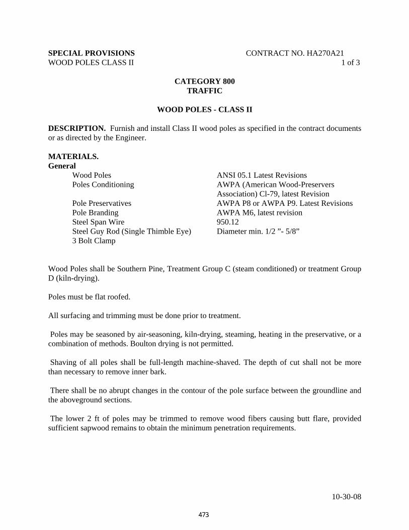
SPECIAL PROVISIONS CONTRACT NO. HA270A21 WOOD POLES CLASS II 1 of 3
10-30-08
CATEGORY 800
TRAFFIC
WOOD POLES - CLASS II DESCRIPTION. Furnish and install Class II wood poles as specified in the contract documents or as directed by the Engineer. MATERIALS. General Wood Poles ANSI 05.1 Latest Revisions Poles Conditioning AWPA (American Wood-Preservers Association) Cl-79, latest Revision Pole Preservatives AWPA P8 or AWPA P9. Latest Revisions Pole Branding AWPA M6, latest revision Steel Span Wire 950.12 Steel Guy Rod (Single Thimble Eye) Diameter min. 1/2 ”- 5/8” 3 Bolt Clamp Wood Poles shall be Southern Pine, Treatment Group C (steam conditioned) or treatment Group D (kiln-drying). Poles must be flat roofed. All surfacing and trimming must be done prior to treatment. Poles may be seasoned by air-seasoning, kiln-drying, steaming, heating in the preservative, or a combination of methods. Boulton drying is not permitted. Shaving of all poles shall be full-length machine-shaved. The depth of cut shall not be more than necessary to remove inner bark. There shall be no abrupt changes in the contour of the pole surface between the groundline and the aboveground sections. The lower 2 ft of poles may be trimmed to remove wood fibers causing butt flare, provided sufficient sapwood remains to obtain the minimum penetration requirements.
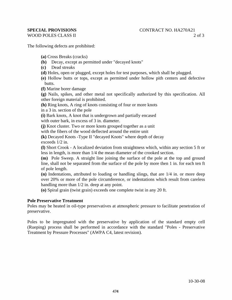
SPECIAL PROVISIONS CONTRACT NO. HA270A21 WOOD POLES CLASS II 2 of 3
10-30-08
The following defects are prohibited: (a) Cross Breaks (cracks) (b) Decay, except as permitted under "decayed knots" (c) Dead streaks (d) Holes, open or plugged, except holes for test purposes, which shall be plugged. (e) Hollow butts or tops, except as permitted under hollow pith centers and defective
butts. (f) Marine borer damage
(g) Nails, spikes, and other metal not specifically authorized by this specification. All other foreign material is prohibited.
(h) Ring knots, A ring of knots consisting of four or more knots in a 3 in. section of the pole (i) Bark knots, A knot that is undergrown and partially encased with outer bark, in excess of 3 in. diameter. (j) Knot cluster. Two or more knots grouped together as a unit with the fibers of the wood deflected around the entire unit (k) Decayed Knots -Type II "decayed Knots" where depth of decay exceeds 1/2 in. (l) Short Crook - A localized deviation from straightness which, within any section 5 ft or
less in length, is more than 1/4 the mean diameter of the crooked section. (m) Pole Sweep. A straight line joining the surface of the pole at the top and ground
line, shall not be separated from the surface of the pole by more then 1 in. for each ten ft of pole length.
(n) Indentations, attributed to loading or handling slings, that are 1/4 in. or more deep over 20% or more of the pole circumference, or indentations which result from careless handling more than 1/2 in. deep at any point.
(o) Spiral grain (twist grain) exceeds one complete twist in any 20 ft. Pole Preservative Treatment Poles may be heated in oil-type preservatives at atmospheric pressure to facilitate penetration of preservative. Poles to be impregnated with the preservative by application of the standard empty cell (Rueping) process shall be performed in accordance with the standard "Poles - Preservative Treatment by Pressure Processes" (AWPA C4, latest revision).

SPECIAL PROVISIONS CONTRACT NO. HA270A21 WOOD POLES CLASS II 3 of 3
10-30-08
No material other than poles shall be treated with poles. The minimum net retention of Pentachlorophenol, as determined from 20 boring samples taken from any charge, shall not be less than the following.
Minimum Retention: (lbs. Penta/cu. ft.) Zone Assayed 0.5 - 2.0 in. Retention .45
Retention of Pentachlorophenol shall be determined by AWPA A5, latest revision. CONSTRUCTION. The following marking and code letter information shall be legibly and permanently burn branded with characters not less than 5/8 in. high. The markings shall be placed squarely on the face of the pole at 10 ft above the pole butt end and in the butt end of each pole in the following order. (1) Supplier's Brand (2) Plant Designation
(3) Month and Year of Treatment (4) Code Letters; "SP" denoting Southern Pine and the preservative code, such as "P"
for Pentachlorophenol in Petroleum (AWPA M-6). (5) Retention and Assay, such as "45-A" (6) Class and Length MEASUREMENT AND PAYMENT. Class II wood poles shall be measured and paid for at the contract unit price each. The payment will be full compensation for the poles, anchors and guy rods all guy cables and connectors, labor, tools, materials, and incidentals necessary to complete this work.

SPECIAL PROVISIONS CONTRACT NO. HA270A21 800 GALVANIZED TRAFFIC SIGNAL PEDESTAL POLES
10-31-08
1 of 5
CATEGORY 800 TRAFFIC
GALVANIZED TRAFFIC SIGNAL PEDESTAL POLES AND
TRANSFORMER BASES
DESCRIPTION. Furnish and install galvanized traffic signal pedestal poles and transformer bases at locations specified in the Contract Document or as directed by the Engineer.
MATERIALS. Design shall meet 2001 edition of AASHTO Standard Specifications for Structural Supports for Highway Signs, Luminaires and Traffic Signals except as noted. All welding shall conform to American Welding Society (AWS) Structural Welding Code D1.1 - Steel, Tubular Structures.
Determine each pedestal pole's height by the total height of the pedestal pole including the transformer base.
(a) 10 ft pole height consists of a 103 in. steel shaft with a steel base plate plus a 17 in. transformer base. (b) 14 ft pole height consists of a 151 in. steel shaft with a steel base plate plus a 17 in. transformer base. (c) 20 ft pole height consists of a 240 in. steel shaft with a steel base plate plus a 17 in. transformer base. Each pedestal pole furnished shall consist of a design from a steel shaft with a steel base plate, transformer base and all miscellaneous hardware.
(a) The pedestal pole shaft shall be fabricated of one length and shall have one
longitudinal weld, parallel to the long axis of the pedestal pole shaft, with no transverse welds. The longitudinal weld shall be finished to form a smooth outside surface and the wall of the pedestal pole shaft shall be uniform in thickness including the welded area. The pedestal pole shaft shall be round or multi-sided (less than eight sides not acceptable) in cross section. 14 ft units shall be uniformly tapered from butt to tip with a 1 in. reduction in diameter for each 7 ft in length (0.14 in./ ft). 10 ft unit shall not be tapered.
(1) 10 ft pedestal pole shaft shall be 4-1/2 in. outside diameter, Schedule 40 pipe,
and conform to A 501.

SPECIAL PROVISIONS CONTRACT NO. HA270A21 800 GALVANIZED TRAFFIC SIGNAL PEDESTAL POLES
10-31-08
2 of 5 (2) All 14 ft pedestal poles shall be 7-1/2 in. outside diameter at the base and shall
be made of 11 gauge (0.119 in.) thickness steel conforming to A 595, Grade A or equivalent.
(3) All 20 ft pedestal poles shall be 7-1/2 in. outside diameter at the base and shall
be made of 3 gauge (0.25 in.) thickness steel conforming to A 595, Grade A or equivalent
(b) The base plate material shall meet the requirements of A 709, Grade 36. The base
plate shall be secured to the lower end of the pedestal pole shaft by two continuous electric arc welds. The base plate shall telescope the pedestal pole shaft with one weld on the inside of the base plate at the end of the pedestal pole shaft. The remaining weld shall be located on the outside of the base plate at the top of the pedestal pole shaft. The weld connection shall develop the full strength of the adjacent pedestal pole shaft to resist bending action. All bases plate shall be fabricated with the holes for anchor bolts to the size and location dimensions as shown in MD-818.16 and 818.17.
(c) 14 ft pedestal poles shall be furnished with entrance ways for cable as noted in the
contract documents. These holes must be factory drilled and a straight tapped coupling, conforming to Underwriters Laboratory's UL-6 Specification, for 2 in. rigid conduits, must be installed for each hole. A nipple with a unitized hexagonal fitting and integral inside radius on one end must then be installed and fully seated on the interior side of the coupling. Location and installation of the coupling shall be as shown in MD-818.17.
(d) All pedestal poles and hardware, except materials manufactured from stainless steel
or cast aluminum, shall be hot dipped galvanized. The galvanized coating shall conform to the thickness, adherence and quality requirements of A 123 and A 153 for hardware. Threaded components shall be chased and cleaned after galvanizing. All internally threaded components shall be tapped oversize the minimum amount required to permit assembly on the coated externally threaded fastener. Internally threaded components shall be provided with a lubricant which shall be clean and dry to the touch.
(e) Each pedestal pole shall be furnished with a removable domed cap, fabricated from
cast aluminum, circumferentially attached to the side of the pole with three hex head type 304 stainless steel bolts (1/4 in. - 20 UNC).
(f) Each pedestal pole shall have an identification plate mechanically attached 6 in.
above the pedestal pole base plate and oriented so that the identification plate may be read from a ground observation position.

SPECIAL PROVISIONS CONTRACT NO. HA270A21 800 GALVANIZED TRAFFIC SIGNAL PEDESTAL POLES
10-31-08
3 of 5 (g) Recessed hub type, galvanized malleable iron plugs shall be inserted flush into all
couplings. Transformer Bases (a) All transformer bases shall be approved by FHWA as meeting breakaway under NCHRP 350.
(b) Each transformer base must be furnished with four hex head bolts, four hex head
nuts and all associated hardware as shown on the appropriate detail for fastening the pedestal pole base plate to the top of the transformer base. All bolts shall conform to A 325 specifications and must be galvanized.
Anchor Bolts (a) Each pedestal pole anchor bolt shall be made of steel conforming to M 314, Grade
55 S1 (b) Anchor bolt threads shall be of cut thread design with a minimum 6 in. of threads at
the top. (c) The template and anchor plates shall be as shown on MD801.01. (d) The diameter of the anchor bolt shall be stamped into the top of the threaded end of
each anchor bolt. (e) Each anchor bolt shall be provided with two attached heavy hex nuts and two
attached flat washers.
(1) Anchor bolt nuts shall conform to A 194, grade 2 or 2H, or A 563, D or DH. (2) All nuts shall be tapped oversize the minimum amount required to permit
assembly on the coated externally threaded fastener. (3) Washers shall conform to F 436.
(f) All nuts, washers, and the top 12 in. of all anchor bolts shall be hot dipped or
mechanically galvanized. The galvanized coating shall conform to the thickness, adherence and quality requirements of A 123 or A 153 for hardware.

SPECIAL PROVISIONS CONTRACT NO. HA270A21 800 GALVANIZED TRAFFIC SIGNAL PEDESTAL POLES
10-31-08
4 of 5
All high strength bolts (of a given length), nuts (of a given size) and washers (of a given diameter) shall be from the same manufacturing lot per each requisition of materials. The use of foreign made fasteners is prohibited!
CONSTRUCTION. Refer to 818.03 MEASUREMENT AND PAYMENT. Pedestal poles will be measured and paid for at the Contract unit price per each type of pole furnished and installed. The payment will be full compensation for furnishing and installing transformer base and all materials , labor, equipment, tools and incidentals necessary to complete work.
Anchor bolts will be measured and paid for as specified in Section 801.

SPECIAL PROVISIONS CONTRACT NO. HA270A21 800 GALVANIZED TRAFFIC SIGNAL PEDESTAL POLES
10-31-08
5 of 5
Tag Detail
Mfg: [ 1 ] Contract #: [ 2 ] Pole Diameter: [ 3 ] Height: [ 4 ] Gauge: [ 5 ] Anchor Bolts: [ 6 ] Bolt Circle: [ 7 ]
Tag Reference [ 1 ] Name of the manufacturer of the pedestal pole. [ 2 ] Administration Contract Number of the pedestal pole. [ 3 ] Pole outside diameter at the base: 4-½ in. O.D. or 7-½ in. O.D. [ 4 ] Pole height1: 10ft' , 14ft, 20 ft [ 5 ] Pole gauge: Schedule 40 or 11 GA [ 6 ] Anchor bolt size: 1 in. Dia. x 40 in. Length [ 7 ] Bolt circle diameter: 11 in. Dia. 1Pole height includes the height of the pedestal pole and transformer base. Typically, the transformer base is 17 in. in height which corresponds to 10 ft pole having a height of 103 in.; and a 14 ft having a height of 151 in

SPECIAL PROVISIONS CONTRACT NO. HA270A21 LED SIGN LUMINAIRES
10-31-08
1 of 2 CATEGORY 800
TRAFFIC
SIGN LUMINAIRES DESCRIPTION. Furnish and install Sign Luminaires as specified in the contract documents or as directed by the Engineer. MATERIALS. Sign luminaire shall have a color temperature of 3900 degrees Kelvin or higher with a high CRI. Each sign luminaire shall be designed for a service life of at least 12 years with 50,000 hours of operation based on a 12 hour on, 12 hour off duty cycle. Sign luminaires shall have a lumen retention of 70 per cent or greater at the end of service life. All components of the luminaire must be rated for the full service life without maintenance. Sign luminaires shall use no more then 135 watts and be designed to operate at the voltage specified in the contract documents. For 480 volt operation, an integral transformer may be provided to reduce the voltage. The power factor of the sign luminaire must be 0.9 or higher. All components of the Sign Luminaire shall be UL approved, and the luminaire shall be UL listed, or in the process of obtaining UL approval. The sign luminaire shall be designed to mount on a standard mounting plate as detailed in the book of standards, and on the standard carriage of a Lumitrak sign lighting system. The sign luminaire housing and lens/refractor shall be sealed to prevent intrusion of moisture for the full service life. The Lens/refractor must be constructed of a material that will not show visible yellowing due to UV exposure, or exposure to hydrocarbon emission, for the full service life CONSTRUCTION. Photometric calculations shall be provided with the catalog cuts for the sign luminaire verifying the sign illumination for a typical sign 14 foot wide and 14 foot high. For the calculations, three luminaires shall be used. These will be placed with the first luminaire two foot from the left edge of the sign, the second 7 foot from the left edge, and the third 12 foot from the left edge. Each luminaires light center shall be 6 foot out from the sign base, and 1.5 ft below the lower edge of the sign. Calculations shall be provided for a grid with vertical and horizontal spacing of 1 foot. The bottom of the grid will be 0.5 foot above the bottom edge of the sign and left edge 0.5 foot from the left side.
2 of 2

SPECIAL PROVISIONS CONTRACT NO. HA270A21 LED SIGN LUMINAIRES
10-31-08
To be acceptable, the average initial illumination shall be 20 foot candles or greater with a maximum to minimum uniformity ration no greater then 6 to 1. The engineer may waive the photometric calculations for sign luminaires that have been previously installed and demonstrated there acceptability, or placed on the qualified products list. MEASUREMENT AND PAYMENT. Sign Luminaires shall be measured and paid for at the contract unit price each for Sign Luminaires. The payment will be full compensation for the Sign Luminaire and drivers, mounting hardware, wiring, step down transformer, photometric calculations, and all material, labor, equipment, tools, and incidentals necessary to complete the work
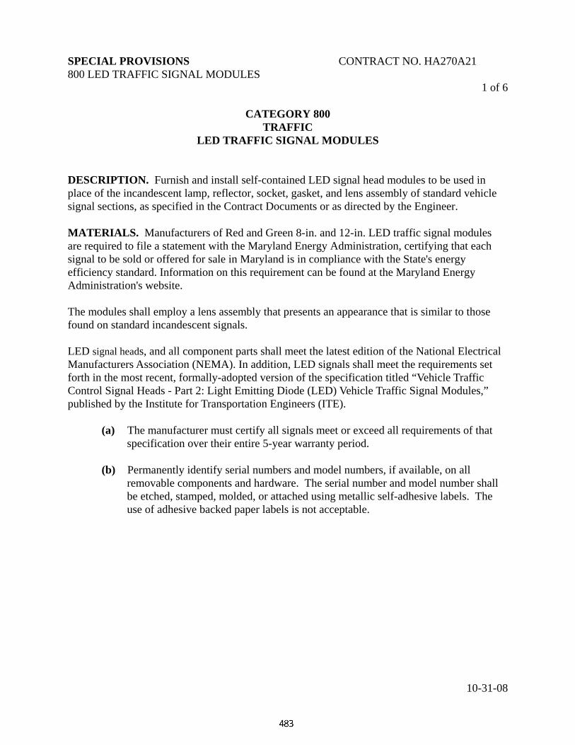
SPECIAL PROVISIONS CONTRACT NO. HA270A21 800 LED TRAFFIC SIGNAL MODULES
10-31-08
1 of 6
CATEGORY 800 TRAFFIC
LED TRAFFIC SIGNAL MODULES
DESCRIPTION. Furnish and install self-contained LED signal head modules to be used in place of the incandescent lamp, reflector, socket, gasket, and lens assembly of standard vehicle signal sections, as specified in the Contract Documents or as directed by the Engineer. MATERIALS. Manufacturers of Red and Green 8-in. and 12-in. LED traffic signal modules are required to file a statement with the Maryland Energy Administration, certifying that each signal to be sold or offered for sale in Maryland is in compliance with the State's energy efficiency standard. Information on this requirement can be found at the Maryland Energy Administration's website. The modules shall employ a lens assembly that presents an appearance that is similar to those found on standard incandescent signals. LED signal heads, and all component parts shall meet the latest edition of the National Electrical Manufacturers Association (NEMA). In addition, LED signals shall meet the requirements set forth in the most recent, formally-adopted version of the specification titled “Vehicle Traffic Control Signal Heads - Part 2: Light Emitting Diode (LED) Vehicle Traffic Signal Modules,” published by the Institute for Transportation Engineers (ITE). (a) The manufacturer must certify all signals meet or exceed all requirements of that
specification over their entire 5-year warranty period. (b) Permanently identify serial numbers and model numbers, if available, on all
removable components and hardware. The serial number and model number shall be etched, stamped, molded, or attached using metallic self-adhesive labels. The use of adhesive backed paper labels is not acceptable.

SPECIAL PROVISIONS CONTRACT NO. HA270A21 800 LED TRAFFIC SIGNAL MODULES
10-31-08
2 of 6
CONSTRUCTION. LED modules shall fit in standard, incandescent vehicle traffic signal housings without modifications or the need for special tools, and shall be complete with a one-piece, integral lens assembly that is tinted for the appropriate color. Design. LED traffic signal modules shall have:
(a) A printed circuit board inclusive of all of the LEDs and required circuit components.
(b) Minimum 39- in. wire leads, minimum # 20 AWG, 600 volt, 105 C, with strain relief and spade terminals. Screw-type terminals shall not be allowed.
(c) A rigid housing for protection in shipping, handling and installation: (d) A one piece neoprene gasket shall be used to seal out water and contaminants. Assembly Techniques.
(a) The LEDs within the modules shall be mounted and soldered to a printed circuit board.
(b) LED signal modules shall be watertight when properly installed in traffic signal housings.
(c) LED signal modules shall utilize the same mounting hardware used to secure a
standard incandescent lens and gasket assembly, and shall only require a screwdriver or basic installation tools to complete the mounting.
(d) LED signal module assemblies shall weigh less than 5 Lb.
(e) LED signal modules may not protrude into the signal visor area more than two and three-quarters of an in. in depth.
(f) LED signal modules shall be marked ‘TOP’ or have an up arrow to designate the
proper orientation of the signal module in the traffic signal housing. (g) LED signal module housings shall utilize an integral metal layer in their design and construction.
(h) LED signal modules shall utilize the latest technology in thermal management..

SPECIAL PROVISIONS CONTRACT NO. HA270A21 800 LED TRAFFIC SIGNAL MODULES
10-31-08
3 of 6 Lenses. Make lenses for ball type modules of ultraviolet stabilized polycarbonate, and incorporate facets that serve to enhance the optical efficiency of the LED traffic signal module. Individual lens-lets or external lens facets shall not be permitted.
(a) The ball type signals shall incorporate a diffuser-type lens system that serves to collimate the light emitted by the LEDs. The lens and diffuser system shall focus the collimated light, to meet ITE intensity and distribution standards.
(b) LED signals shall almost perfectly approximate the appearance of an incandescent
traffic signal to the motorist. (1) The face of the ball LED lamps shall appear to the motorist as uniform in
illumination, and have a wide viewing angle that makes it suitable for installation on wide boulevards.
(2) The external lens surface for all vehicle signals shall be smooth, with no raised features, so as to minimize the collection of dirt, diesel smoke, and other particulate contaminates, and to facilitate periodic cleaning.
(3) The lens shall be keyed to the housing of the LED signal module to insure the proper orientation and to avoid possible rotation during any handling.
(4) Hard coat external lenses to prevent an accumulation of dust and dirt.
(5) For LED turn arrow signals, the LED arrow lens may be a replaceable part without the need to replace the complete LED arrow.
Optical. The light intensity, chromaticity, and distribution from eight and twelve-in. Red and Green, and eight-in. Yellow LED traffic signal modules shall meet all photometric values stated in the most recent, formally-adopted version of the specification titled “Vehicle Traffic Control Signal heads – Part 2: Light Emitting Diode (LED) Vehicle Traffic Signal Modules,” published by the Institute for Transportation Engineers (ITE). Twelve-in. Yellow LED traffic signal modules shall meet the chromaticity requirements of the most recently-adopted ITE specification, with a minimum intensity of 1,500 candelas.
(a) Red and Green LED signals shall be certified by the manufacturer to meet or exceed all requirements of that specification over their entire 5-year warranty period.
(b) The light output from twelve-in. Yellow LED signals shall be the peak instantaneous intensity, measured at instant-on and at the highest intensity point.

SPECIAL PROVISIONS CONTRACT NO. HA270A21 800 LED TRAFFIC SIGNAL MODULES
10-31-08
4 of 6 Design.
(a) The LEDs shall be connected in series-parallel strings.
(1) No more than 1 percent of the total luminosity of the entire signal module may be lost in the event of a single string failure.
(2) The failure of a single LED shall cause loss of light from only that LED. (3) No loss of light output from the complete module assembly shall occur as a
result of a single LED failure.
(b) The control circuitry shall prevent the current flow through the LEDs in the off state to avoid any false indication as may be perceived by the human eye, during daylight and evening hours.
(1) The LED traffic signal module shall be operationally compatible with NEMA
TS – 1 and NEMA TS – 2 conflict monitoring parameters. (2) The intensity of the LED signal module shall not vary by more than 10percent
over the allowable voltage range as specified in the electrical section below.
Electrical. (a) The Power factor shall be 0.90 or greater, at nominal rated voltage, at 25°C, after
60 minutes of operation.
(b) Total harmonic distortion (THD) shall be less than 20 percent at rated voltage, at 25°C.
© All LED traffic signal modules shall be in compliance with FCC noise regulations and must meet the FCC Title 47, SubPart B Section 15 regulation.
(d) The LED junction technology used in all signal modules shall not exhibit
degradation of more than 30percent of the modules’ initial light intensity following accelerated life testing (operating at 85 degrees C and 85percent humidity, for 1000 hours). Under no circumstances shall AlGaAs technology be acceptable.
(e) The LED signal modules shall be connected directly to line voltage, 120 Volts AC
nominal, and shall be able to operate over the voltage range of 80 VAC to 135 VAC.
5 of 6

SPECIAL PROVISIONS CONTRACT NO. HA270A21 800 LED TRAFFIC SIGNAL MODULES
10-31-08
(f) Red and Green LED traffic signal modules shall consume no more than a nominal
15 watts for either the 8” or 12” signal. Yellow signal modules shall consume no more than 24 watts.
(g) Transient voltage suppression rated at 1500 watts for 1 millisecond and fusing with
a maximum rating of 2 amps shall be provided to minimize the effect and repair cost of an extreme over voltage situation or other failure mode.
(h) Low Voltage Turn OFF: There shall be no visible illumination from the LED signal
module when the applied voltage is less than 50 VAC.
(i) Turn-ON and Turn-OFF Time: A module shall reach 90percent of full illumination (turn-ON) within 75 msec of the application of the nominal operating voltage. The signal shall cease emitting visible illumination (turn-OFF) within 75 msec of the removal of the nominal operating voltage.
Compatibility Testing: The LED module manufacturer shall certify that their modules meet the Load Switch and Signal Conflict Monitor Compatibility testing requirements found in the most recent, formally-adopted version of the specification titled “Vehicle Traffic Control Signal heads - Part 2: Light Emitting Diode (LED) Vehicle Traffic Signal Modules,” published by the Institute for Transportation Engineers (ITE). Electronic Failure Protection. To assure compatibility with NEMA TS1/TS2 controllers for both conflict monitoring and Red Fail, all signal colors (Red, Yellow, and Green) once energized, must turn off prior to 50VAC, and if the signal fails it shall present a high impedance on the input side of the signal. Warranty. Manufacturers shall provide a written with the following minimum provisions: (a) Modules shall be replaced, repaired or purchase value refunded if the module fails to
function as intended due to workmanship or material defects within the first 60 months from the date of delivery.
(b) Modules which exhibit luminous intensities less than the minimum specified values
within the first 60 months of the date of delivery shall be replaced, repaired or purchase value refunded.
6 of 6 Miscellaneous. The manufacturers part number, date code, and electrical characteristics of the

SPECIAL PROVISIONS CONTRACT NO. HA270A21 800 LED TRAFFIC SIGNAL MODULES
10-31-08
LED signal module shall be visible on the rear of the assembly. MEASUREMENT AND PAYMENT. Self-contained LED signal head modules will be measured and paid for at the contract unit price each. The payment will be full compensation for the LED module, hardware, assembly, and for all material, labor, equipment, tools, and incidentals necessary to complete the work.

SPECIAL PROVISIONS CONTRACT NO. HA270A21 MAST ARMS AND MAST ARM POLES
10-31-08
1 of 12
CATEGORY 800 TRAFFIC
MAST ARMS AND MAST ARM POLES -
SINGLE, TWIN AND TRIPLE DESCRIPTION. Furnish and install galvanized traffic signal mast arms and mast arm poles at locations specified in the Contract Document or as directed by the Engineer. MATERIALS. Design shall meet the 2001 edition of AASHTO Standard Specifications for Structural Supports for Highway Signs, Luminaires and Traffic Signals except as noted. All welding shall conform to American Welding Society (AWS) Structural Welding Code D1.1 - Steel, Tubular Structures. Each mast arm(s) and mast arm pole structure furnished shall consist of a design from a steel pole shaft with a steel base plate and flange plate, steel mast arm shaft(s) with steel flange plate(s), four flange bolts per mast arm, four anchor bolts and miscellaneous hardware. (a) Manufacture the mast arms and mast arm poles from steel tubing conforming to A 595
Grade A or equal. Each mast arm and mast arm pole shall be fabricated of one length and shall have one longitudinal weld, parallel to the long axis of the mast arm or mast arm pole, with no transverse welds. Finish the longitudinal weld to form a smooth outside surface and the wall of the mast arms and mast arm poles shall be of uniform thickness including the welded area. The mast arms and mast arm poles shall be round or multi-sided ( 8 sides or more ) in cross section and be uniformly tapered from butt to tip with a 1 in. reduction in diameter for each 7 ft in length (0.14 in./ ft). Mast arms shall be of two piece design for all mast arms 50 ft and 60 ft in length. Mast arms shall be of three piece design for all mast arms 70 ft in length. Any combination of two piece of 50 ft and 60 ft arms of the same butt diameter shall fit together and any combination of two or three piece of 60 ft and 70 ft mast arms in sequence shall fit together. The bolted splice for two or three piece mast arms shall be as specified in the Contract Document. (1) 50 ft mast arms shall have a butt section 30 ft in length. (2) 60 ft and 70 ft mast arms shall have a butt section of 35 ft in length. (3) 38 ft single piece mast arms shall be 9 in. outside diameter at the flange plate and
made of 7 gauge (0.179 in.) thickness steel.

SPECIAL PROVISIONS CONTRACT NO. HA270A21 MAST ARMS AND MAST ARM POLES
10-31-08
2 of 12 (4) 50 ft two piece mast arm butt sections shall be 10 in. outside diameter at the flange
plate and made of 3 gauge (0.250 in.) thickness steel.
(5) 60 ft two piece and 70 ft three piece mast arm butt sections shall be 12.5 in. outside diameter at the flange plate and made of 3 gauge (0. 250 in.) thickness steel.
(6) All extension sections of two and three piece mast arms shall be made of 7 gauge
(0.179 in.) thickness steel. (7) Single 27 ft mast arm pole designed with a 38 ft mast arm length shall be 12 in.
outside diameter at the base plate and made of 7 gauge (0.179 in.) thickness steel. (8) Single 27 ft mast arm pole designed with a 50 ft mast arm length shall be 13 in.
outside diameter at the base plate and made of 3 gauge (0.250 in.) thickness steel. (9) Single 27 ft mast arm pole designed with 60 ft or 70 ft mast arm lengths shall be 15
in. outside diameter at the base plate and made of zero gauge (0.312 in.) thickness steel.
(10) Twin 27 ft mast arm poles designed with 50 ft mast arm lengths shall be 13 in.
outside diameter at the base plate base and made of 3 gauge (0.250 in.) thickness steel.
(11) Twin 27 ft mast arm poles designed with mast arm lengths for one mast arm of 50 ft
and the remaining mast arm of 60 ft or 70 ft shall be 15 in. outside diameter at the base plate and made of zero gauge (0.312 in.) thickness steel.
(12) Triple 27 ft mast arm pole designed with mast arm lengths for one mast arm of 38
ft, second mast arm of 60 or 70 ft and the third mast arm of 50 ft shall have 15 in. outside diameter at the base plate and made of zero gauge (0.312 in.) thickness steel.
(b) The material for mast arm pole base plate shall conform to A 709, Grade 36 and shall
be of sufficient size and strength. Secure the base plate to the lower end of the mast arm pole by two continuous electric arc welds. The base plate must telescope the mast arm pole with one weld on the inside of the base plate at the end of the mast arm pole shaft. Locate the remaining weld on the outside of the base plate, around the circumference of the mast arm pole. The weld connection shall develop the full strength of the adjacent mast arm pole shaft to resist bending action. Fabricate all base plates with the holes for anchor bolts to the size and location dimensions as shown on the appropriate detail.

SPECIAL PROVISIONS CONTRACT NO. HA270A21 MAST ARMS AND MAST ARM POLES
10-31-08
3 of 12
(c) All mast arms and mast arm poles must be furnished with flange plate(s) as noted in the
details. Connect these attachments, including the bolts, in such a manner as to develop the minimum guaranteed yield and ultimate tensile strength for the mast arm and mast arm pole. This assembly shall be capable of transferring the maximum moment being carried by the mast arm without distortion or rotation of the mast arm or the attachment. Connect flange plate(s) by the use of 4 bolts. The size of the plates and bolts shall be as shown in the details. Furnish four (1-1/2 in. O.D.) rubber grommets for each mast arm to accommodate signal heads wiring access.
(d) Secure the mast arm flange plate to the lower end of the mast arm pole by two continuous
electric arc welds. The mast arm flange plate shall telescope the mast arm with one weld located on the inside of the flange plate at the end of the mast arm. Locate the remaining weld on the outside surface of the flange plate around the circumference of the mast arm pole. The weld connections shall develop the full strength of the adjacent mast arm to resist bending action.
(e) Mast arm flange plates and mast arm pole flange plates surfaces shall be plane to within
1/16 in. and shall be free of any buildup of galvanizing (drips, runs, etc.) which would prevent intimate contact between the connecting surfaces.
(f) Weld access hole frames into the mast arm pole as detailed in MD 818.11. A galvanized
steel cover, conforming to A 709, Grade 36 shall cover the access hole frame. Secure the access hole cover's top to the access hole frame by a hinge fabricated from 0.063 in. stainless steel using a 0.120 in. diameter stainless steel hinge pin. Secure the hinge to the access hole frame with 2 ( 1/4 in. - 20 UNC) hex head stainless steel bolts. Secure the hinge access hole cover by 2 ( 1/4 in. - 20 UNC) hex head stainless steel bolts and lock nuts. Provide a slotted opening at the bottom of the access hole cover to allow for attachment of a furnished (1/4 in. - 20 UNC) hex head stainless steel bolt into the access hole frame face.
(g) A 3/8 in. diameter X 1 in. stud copper servit post for two #6 AWG stranded wire shall be
furnished into the bottom of the access hole frame. (h) Provide mast arm poles with entrance ways for cable as noted on the appropriate detail.
These holes shall be factory drilled and a straight tapped coupling, conforming to Underwriters Laboratory's UL-6 Specification, for 3 in. rigid conduits, shall be installed for each hole. A nipple with a unitized hexagonal fitting and integral inside radius on one end shall then be installed and fully seated on the interior side of the coupling. Location and installation of the coupling shall be as shown in the details.

SPECIAL PROVISIONS CONTRACT NO. HA270A21 MAST ARMS AND MAST ARM POLES
10-31-08
4 of 12 (i) Install "J" hooks as follows, located 1 ft above the highest mast arm T dimension.
(1) Weld a single "J" hook inside the pole for single mast arm poles. (2) Weld two "J" hooks inside the pole for twin mast arm poles and triple mast arm
poles. (j) Hot dip galvanize all mast arms, mast arm poles, access hole frames and hardware,
except materials manufactured from stainless steel or cast aluminum. The galvanized coating shall conform to the thickness, adherence and quality requirements of A 123 or A 153 for hardware. Chase and clean threaded components after galvanizing. Tap all internally threaded components the minimum amount required to permit assembly on the coated externally threaded fastener. Provide internally threaded components with a lubricant which shall be clean and dry to the touch.
(k) Furnish each mast arm pole with four removable ornamental anchor bolt covers made of
cast aluminum. Bolt holes for attaching the bolt covers to the base plate shall be drilled at the location obtained by following the diagonal line of the base plate until it intersects the bolt circle diameter, then proceeding tangentially from the bolt circle diameter a distance equal to the Anchor Bolt Center to Bolt Slot Center Distance as provided in the MD 818.14. Attachment to the base shall be made using hex head stainless steel bolts (1/4 in.- 20 UNC).
(l) Furnish each mast arm extension section and mast arm pole with a removable domed cap,
fabricated from cast aluminum, circumferentially attached to the outside of the pole shaft or mast arm end with 3 hex head stainless steel bolts (1/4 in.- 20 UNC). All mast arm caps shall have inside diameter one in. Larger than the outside diameter of mast arm end.
(m) Each mast arm and mast arm pole shall have an identification plate mechanically
attached, oriented such that the identification plate may be read from a ground observation position.
(1) Single piece mast arms and the butt section of two and three piece mast arms shall
have the identification plate attached 6 in. above the flange plate. (2) Each extension section of two and three piece mast arms shall have the
identification plate attached 6 in. from the larger diameter end. (3) Poles shall have the identification plate attached 6 in. above the bottom flange plate.
(n) Insert recessed hub type, galvanized malleable iron plugs flush into all mast arm pole couplings.
5 of 12

SPECIAL PROVISIONS CONTRACT NO. HA270A21 MAST ARMS AND MAST ARM POLES
10-31-08
Anchor Bolts. (a) Make each mast arm pole anchor bolt of steel in accordance with F1554, Grade 55 S1. (b) Anchor bolt threads shall be of cut thread design with a minimum 9 in. of threads at the
top and bottom. (c) The template and anchor plates shall be as shown the contract documents. (d) Stamp the diameter of the anchor bolt into the top of the threaded end of each anchor
bolt. (e) Provide each anchor bolt with two anchor bolt nuts and two flat washers.
(1) Anchor bolt nuts shall conform to A 194 grade 2 or 2H or A 563 D or DH.
(2) Tap all nuts oversize the minimum amount required to permit assembly on the coated externally threaded fastener.
(3) Washers shall conform to F436.
(f) Hot dip or mechanically galvanize all nuts, washers and the top 12 in. of all anchor bolts.
The galvanized coating shall conform to the thickness, adherence and quality requirements of A 123 or A 153 for hardware.
All high strength bolts (of a given length), nuts (of a given size) and washers (of a given diameter) shall be from the same manufacturing lot per each requisition of materials. The use of foreign made fasteners is prohibited! Alternate Design. Alternate mast arm and mast arm pole designs will be considered provided the following qualifications are observed: (a) Alternate mast arm designs may use sectional construction provided each section has a
minimum length of 30 ft except for the outer most section. (b) Overlap between sections shall be a minimum 18 in. (c) Bolt circle diameters shall be as specified in the Contract Document. (d) Alternate post designs may be straight (not tapered) sections and shall have a base
diameter equal to, or no greater than 1 in. more than, those values shown on the typicals.
(e) All alternate design must be structurally equivalent to the original design and as approved by the Engineer.

SPECIAL PROVISIONS CONTRACT NO. HA270A21 MAST ARMS AND MAST ARM POLES
10-31-08
6 of 12 CONSTRUCTION Refer to 818.03 MEASUREMENT AND PAYMENT MEASUREMENT AND PAYMENT. Furnish and install poles for mast arm(s) and mast arm(s) will be measured and paid for at the contract unit price per each type of pole and mast arm(s) size as specified in the Contract Document. The payment will be full compensation for furnishing & installing all materials including labor, equipment, materials, tools and incidentals necessary to complete the work. Anchor bolts will be measured and paid for as specified in section 801.

SPECIAL PROVISIONS CONTRACT NO. HA270A21 MAST ARMS AND MAST ARM POLES
10-31-08
7 of 12 Tag Details
Single Mast Arm Pole Mfg: [ 1 ] Contract. #: [ 2 ] Pole Height: [ 3 ] Arm Sizes: [ 4 ] Anchor Bolts: [ 5 ] Bolt Circle: [ 8 ] Flange Bolts: [ 7 ]
One Piece Mast Arm Mfg: [ 1 ] Contract #: [ 2 ] Arm Length: [ 6 ] Flange Bolts: [ 7 ]
Two or three Piece Mast Arm - Butt Section Mfg: [ 1 ] Contract #: [ 2 ] Butt For Arms: [ 4 ] Flange Bolts: [ 7 ] Connection Bolt: [ 9 ]

SPECIAL PROVISIONS CONTRACT NO. HA270A21 MAST ARMS AND MAST ARM POLES
10-31-08
8 of 12
Two or three Piece Mast Arm – Extension Section Mfg: [ 1 ] Contract #: [ 2 ] Extension Arm: [ 6 ] Connection Bolt: [ 9 ]
Twin Mast Arm Pole (Identical Size Flange Plates) Mfg: [ 1 ] Contract #: [ 2 ] Pole Height: [ 3 ] Arm Sizes: [ 4 ] Anchor Bolts: [ 5 ] Bolt Circle: [ 8 ] Flange Bolts: [ 7 ]
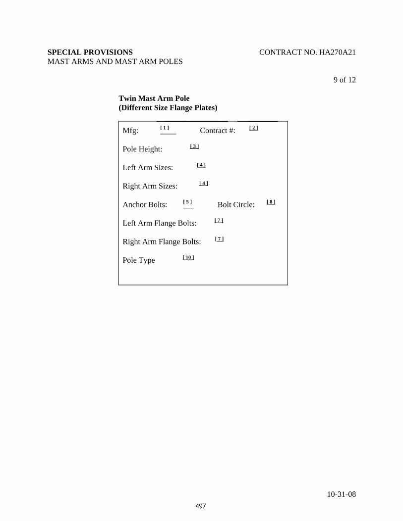
SPECIAL PROVISIONS CONTRACT NO. HA270A21 MAST ARMS AND MAST ARM POLES
10-31-08
9 of 12
Twin Mast Arm Pole (Different Size Flange Plates) Mfg: [ 1 ] Contract #: [ 2 ] Pole Height: [ 3 ] Left Arm Sizes: [ 4 ] Right Arm Sizes: [ 4 ] Anchor Bolts: [ 5 ] Bolt Circle: [ 8 ] Left Arm Flange Bolts: [ 7 ] Right Arm Flange Bolts: [ 7 ]
Pole Type [ 10 ]
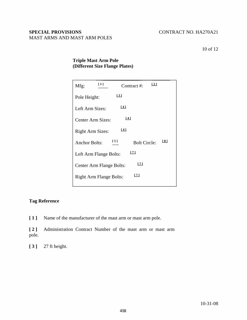
SPECIAL PROVISIONS CONTRACT NO. HA270A21 MAST ARMS AND MAST ARM POLES
10-31-08
10 of 12
Triple Mast Arm Pole (Different Size Flange Plates) Mfg: [ 1 ] Contract #: [ 2 ] Pole Height: [ 3 ] Left Arm Sizes: [ 4 ] Center Arm Sizes: [ 4 ] Right Arm Sizes: [ 4 ] Anchor Bolts: [ 5 ] Bolt Circle: [ 8 ] Left Arm Flange Bolts: [ 7 ] Center Arm Flange Bolts: [ 7 ] Right Arm Flange Bolts: [ 7 ]
Tag Reference [ 1 ] Name of the manufacturer of the mast arm or mast arm pole. [ 2 ] Administration Contract Number of the mast arm or mast arm pole. [ 3 ] 27 ft height.

SPECIAL PROVISIONS CONTRACT NO. HA270A21 MAST ARMS AND MAST ARM POLES
10-31-08
11 of 12
[ 4 ] Mast Arm Size and Orientation1 Pole Gauge Size Indicate 7 GA 38' 3 GA 50' 0 GA 60' or 70' [ 5 ] Anchor Bolts Pole Gauge Size Indicate 7 GA 1-½" x 54" & 2 Washers 3 GA 1-¾" x 66" & 2 washers 0 GA 2" x 72" & 2 washers [ 6 ] Mast Arm Length - Constructed Extension for arm length Indicate 50' 50' 60' 60'-70' 70' 70' [ 7 ] Flange Bolt Size2 Pole Gauge Size Indicate 7 GA 1-¼" x 4" & washer 3 GA 1-½" x 5" & washer 0 GA 1-¼" x 6-½" & 2 flat washers & lock washer
1For twin mast arm poles with identical size flange plates, indicate L & R preceding the 50' mast arm size; for twin mast arm poles with different size flange plates, indicate either 50' or 60'-70' mast arm sizes in the corresponding Left Arm Size or Right Arm Size as oriented by the line bisecting the acute angle formed by the two mast arm pole flange plates. For triple mast arm poles with different size flange plates, indicate either 50', 60'-70' or 38' mast arm sizes in the corresponding Left Arm Size, Center Arm Size or Right Arm Size as oriented by the centerline of the mast arm pole center flange plate.
2For twin mast arm poles with identical size flange plates, indicate L & R preceding the 1-½" x 5" & washer Flange Bolt Size; for twin mast arm poles with different size flange plates, indicate either 1-½" x 5" & washer or 1-¼" x 6-½" & 2 flat washers & lock washer flange bolt sizes in the corresponding Left Flange Bolt Size or Right Flange Bolt Size as oriented by the line bisecting the acute angle formed by the two mast arm pole flange plates. For triple mast arm poles with different size flange plates, indicate either 1-½" x 5" & washer, 1-¼" x 6-½" & 2 flat washers & lock washer or 1-¼" x 4" & washer flange bolt sizes in the corresponding Left Flange Bolt Size, Center Flange Bolt Size or Right Flange Bolt size as oriented by the centerline of the mast arm pole center flange plate.

SPECIAL PROVISIONS CONTRACT NO. HA270A21 MAST ARMS AND MAST ARM POLES
10-31-08
12 of 12
[ 8 ] Bolt Circle Pole Gauge Size Indicate 7 GA 16" Dia. 3 GA 18" Dia. 0 GA 22" Dia. [ 9 ] Connection Bolt Size Two or three Piece Arm Size Indicate3 50' 5/8" x Var. 60' 5/8" x Var. 70' 5/8" x Var. [ 10 ] Standard or Alternate Twin.
3Length to be determined by the successful bidder.
SPECIAL PROVISIONS CONTRACT NO. HA270A21 800-NON-INVASIVE, MAGNETO-INDUCTIVE MICROLOOP DETECTOR
10-31-08
1 of 3 CATEGORY 800
TRAFFIC
NON-INVASIVE, MAGNETO-INDUCTIVE MICROLOOP DETECTOR DESCRIPTION. Furnish and install non-invasive, magneto-inductive microloop vehicle detection sensors/probes. Install the sensors/probes as a set or assembly of three (3) per traveled lane. MATERIALS. All materials and equipment furnished and installed must be new corrosion resistant, and approved by the Engineer. Manufacturer’s certifications or certified copies of reports of tests shall be furnished as directed by the Engineer. CONSTRUCTION. (a) Vehicle data collection requirements.
(1) Each non-invasive sensor shall have an inductance change that will allow an appropriately designed, matched inductive loop vehicle detector to detect all licensable vehicles that contain ferromagnetic material. The sensor will detect these vehicles when they are within a travel distance less than one half the height of the ferromagnetic material of the vehicle.
(2) The non-invasive vehicle sensing assemblies shall consist of three sensors connected in
series to a common lead in wire.
(3) Connect each non-invasive, magneto-inductive vehicle sensing assembly to an appropriately designed, matched inductive loop vehicle detector.
(4) Optimize traffic data collection or traffic flow parameter measurements across diverse
roadway geometry by installing, triple non-invasive sensor assemblies.
(b) Electrical and magnetic requirements
(1) The non-invasive sensor shall convert changes in the ambient magnetic field to changes in its inductance. An increase in the ambient magnetic field shall result in a decrease in the inductance of the non-invasive sensor, and the inductance change of the non-invasive sensor shall be directly proportional to the changes in the earth’s magnetic field.

SPECIAL PROVISIONS CONTRACT NO. HA270A21 800-NON-INVASIVE, MAGNETO-INDUCTIVE MICROLOOP DETECTOR
10-31-08
2 of 3 (2) The nominal magnitude of the vertical magnetic field over which the non-invasive sensor
shall function to specified requirements shall be 200 millioerstads to 800 millioerstads. The non-invasive sensor shall detect reliably and consistently changes in the ambient magnetic field of seven (7) millioerstad or greater when the earth’s magnetic field is ≥200 millioersted (HDC=200 mOe) and the peak-to-peak amplitude of the applied inductive current is 40 mAmpp-p (IAC = 40 mAmpp-p). This requirement defines the sensitivity to be ≥ 2 nanohenries/millioerstad at HDC=200 mOe and IAC = 40 mAmpp-p.
(3) The sensor/probe inductance shall be between 50 μH to 80 μH. The nominal operating
frequency of the probe shall be between 20 kHz and 60 kHz. The non-invasive sensor shall operate with drive currents of 2.5 mAmpp-p to 175 mAmpp-p. The specified electrical and operating requirements shall be maintained over temperatures ranging from –29.9 F to 162.5 F
(c) Sensor physical requirements. The non-invasive sensor shall have a maximum outer
diameter of 0.8125 in. and a maximum height of 2.25 in. and shall be suitably sealed for use in 100 percent humidity environments within a conduit. Equipment shall be included to secure the probes in the conduit, ensure proper orientation during installation, and maintain proper orientation through life of the device. The sensors shall have pull chords to facilitate installation and removal from the conduit. The probes shall be designed to be easily assembled on-site without the use of special tools and equipment. The sensors shall be serviceable from adjacent handholes. Installation of sensors shall not disturb roadway surface.
(d) Conduit installation requirements.
(1) For detection locations that shall require new conduit installation, the conduit shall be a 3
in.conduit consisting of schedule 80 PVC with an inner diameter of 2.9 in. and an outer diameter of 3.5 in. The conduit shall be installed at a nominal centerline depth of 20 in. from the road surface following the roadway crownline. The depth of the conduit centerline from the road surface shall be maintained between 18 and 22 in. over its entire length. The centerline of the conduit shall not deviate horizontally more than required by the application, however, any deviation in conduit alignment shall be less than 0.25 in. per foot. At least one end of the conduit shall terminate at a standard size handhole with a nominal 24 inch diameter and extend three in into the handhole, and the conduit shall have a grade to permit drainage.

SPECIAL PROVISIONS CONTRACT NO. HA270A21 800-NON-INVASIVE, MAGNETO-INDUCTIVE MICROLOOP DETECTOR
10-31-08
3 of 3
(2) The non-invasive probes shall function in 3 in. conduits that have been previously installed at greater than the optimum operational depth stated above. Non-invasive probe installation and alignment for non-optimum pavement depths shall be performed as directed by the Engineer or described in the contract plans.
(e) Probe lead-in cable. The cable leading from each probe set or assembly to the controller
shall be included with the probes.
(f) Requirement of verification of proper installation
(1) Provide a log of the boring depth measured every 2 ft in boring distance. (2) Verify that the non-invasive sensor set or assembly and lead-in cable installation meets
requirements by measuring the inductance of the non-invasive sensor assembly with a properly designed, matched vehicle detector. The installer shall verify that the installation meets requirements by measuring the DC resistance of the non-invasive sensor assembly with a properly calibrated ohm meter. The installer shall measure the change in inductance of the installed non-invasive sensor assembly using a properly designed, matched vehicle detector when a standard, midsize vehicle is driven directly over the sensor.
Provide a log of the measured inductance, DC resistance and the change in inductance for each installed non-invasive sensor assembly.
(3) The inductance shall be the sum of probe inductance, inductance of lead-in cable (16.5 μH per 100 ft) and home-run cable (23 μH per 100 ft ) and shall be within ±20 per cent of the calculated inductance. The measured DC resistance shall be the sum of 1.5 ohms per probe, 3.0 ohms per 100 ft of lead-in wire and 2.0 ohms per 100 ft of home-run cable and shall be within ±20% of the calculated DC resistance. The measured change in inductance for a standard midsize vehicle shall be in the range from 120 nH to 1200 nH.
MEASUREMENT OF PAYMENT. Non-invasive Magneto Inductive Vehicle Detectors shall be measured and paid for at the contract unit price per each in the cable length specified. The payment will be full compensation for furnishing and installing one probe set, lead-in cable from the probe set to the field cabinet, probe carrier system, pull rope and all other incidentals. The payment shall be full compensation for all materials, labor, equipment and all other incidentals necessary to complete this work. Conduit will be measured and paid for as specified in section 805.

SPECIAL PROVISIONS CONTRACT NO. HA270A21 PAINTING WEATHERED GALVANIZED STRUCTURES
10-31-08¶
1 of 2 CATEGORY 800
TRAFFIC
PAINTING WEATHERED GALVANIZED STRUCTURES
DESCRIPTION. Painting weathered galvanized steel structures including exposed anchor bolts, flange bolts, nuts, and washers as specified in the Contract Documents or as directed by the Engineer. Colors shall be as specified in the Contract Documents MATERIALS: Materials shall conform to the requirements described below. All coatings in the system shall come from the same manufacturer. The Manufacturer shall be on the “Approved List of Manufacturers” maintained by the Office of Materials and Technology, Metals, Coatings and Structural Materials Team.
Organic Zinc Rich Primer Section 912.02.03. Polyamide Epoxy Section 912.03.02. Aliphatic Polyurethane Section 912.04.02.
Colors shall conform to the following Federal Standards or as specified in the Contract Documents. Brown Federal Standard Number 595a-20040 Black Federal Standard Number 595a-27038 Green Federal Standard Number 595a-24108 CONSTRUCTION. SURFACE PREPARATION : Inspect each structure prior to the application of any coating to ascertain the condition and thickness of the weathered zinc coating. This inspection shall determine the required surface preparation. Any or all of the following may exist on any given structure. The following are the possible surface conditions and their required surface preparation:
When a structure exhibits only bright galvanizing, thickness readings are required to insure that 2.5 mils minimum galvanizing remains. Surface preparation shall be SSPC SP-1 (Solvent Cleaning), followed by either SSPC SP-2 (Hand Tool Cleaning) or SSPC SP-7 (Brush Off Blast Cleaning). A minimum 1 mil surface profile shall be obtained.

SPECIAL PROVISIONS CONTRACT NO. HA270A21 PAINTING WEATHERED GALVANIZED STRUCTURES
10-31-08¶
When a structure exhibits a dull gray finish, take thickness readings in the dull gray areas to insure a minimum of 2.5 mils galvanizing remains. Surface preparation shall be SSPC SP-1 (Solvent Cleaning), followed by Power Washing using a pressure washer with the pressure not to exceed 1450 psi at the nozzle. When a structure exhibits areas of white powder coating, surface preparation shall be SSPC SP-1 (Solvent Cleaning) followed by SSPC SP-2 (Hand Tool Cleaning). After the white powder has been removed, take thickness readings to insure a minimum 2.5 mils galvanizing remains. A minimum 1 mil surface profile must be obtained.
When a structure exhibits areas of red rust, take thickness readings to see if any galvanizing remains. Surface preparation shall be SSPC SP-1 (Solvent Cleaning), followed by SSPC SP-11 (Power Tool Cleaning to Near White). A minimum surface profile of 1 mil shall be obtained.
PAINTING: Paint the structures using the following materials.
Spot prime areas where there is less than 2.5 mils of galvanizing using Organic Zinc Primer at the manufacturers recommended thickness. Apply a full coat of Polyamide Epoxy to the entire structure at the manufacturer’s recommended thickness. There may be a recoat window for this material.
Apply a finish coat of Aliphatic Polyurethane to the entire structure at the manufacturers recommended thickness.
The finished painted surface must be holiday free when tested with a low voltage holiday detector (minimum 30 volts) similar to a K – D Bird Dog, using regular tap water. If holidays are detected, the coatings could be repaired with additional coatings or they may be stripped and repainted at the coaters’ expense.
Apply all coatings in accordance with manufacturers recommendations. Paint all structures within twenty-four (24) hours after surface preparation. If this time is exceeded, re-inspection will be necessary to insure no contamination of the cleaned surface has occurred prior to painting. Additional surface preparation may then be necessary. MEASUREMENT AND PAYMENT. Painting of weathered galvanized structures will be measured and paid for at the Contract unit price per each structure. The payment will be full compensation for all material, labor, equipment, tools and incidentals necessary to complete the work.

SPECIAL PROVISIONS CONTRACT NO. HA270A21 RED SIGNAL AHEAD LED SIGNS
10-31-08
1 of 3 CATEGORY 800
TRAFFIC
RED SIGNAL AHEAD LED SIGNS DESCRIPTION. Furnish and Instal signs with all or part of their legend formed by Light Emitting Diodes (LED’s). MATERIALS. Sign Supports and Hardware 909.07 Reflective and Non Reflective Sheeting 950.03 Sign Materials 950.08 General: The signs shall be designed to function in an outdoor environment, be fully weather tight, and function at an ambient temperature of -37 to 48 degrees Celsius. The sign shall be in full compliance with the MUTCD. The legend formed by LED’s must be clearly legible at 400 ft, and visible at 1000 ft, along the optical axis of the LED sign when the LED’s are energized and the sign is viewed against a clear daylight sky. When the LED’s are not energized the LED's shall not be evident. Light Emitting Diodes: LED's shall be Aluminum Indium Gallium Phosphide type. The LED shall be rated for 100000 hours continuous operation with no more than 50% lumen depreciation. Each LED shall provide at least 500 millicandelas on the optical axis with a 20 degree or greater beam angle, at 20 milliamps. Red LED's shall have a dominant wavelength of the emitted light between 620 and 660 NM. CONSTRUCTION: Light Emitting Diodes: The LED's shall be securely soldered into a printed circuit board. The boards shall be arranged so that the failure of any one LED will not deactivate any other LED. The current supplied to each LED shall not vary more then 5% from any other LED. Pixels: The LED's shall be grouped to form individual pixels. Each pixel shall be between 1 in. and 1.25 in. diameter. Each pixel shall have a luminance greater then 35 candela along the optical axis, at 20 milliamps operating current per LED. The pixel, and associated circuit board, shall be mounted into the module in such a manner as to allow easy access for repair. The pixel shall be watertight when properly installed.

SPECIAL PROVISIONS CONTRACT NO. HA270A21 RED SIGNAL AHEAD LED SIGNS
10-31-08
2 of 3 Each pixel shall contain internal circuitry for 125 VAC operating voltage. External Power supplies are not allowed. The pixel shall have 6 in. 18 AWG wire leads that are color coded to indicate the color output of the pixel. Each pixel housing shall be made from brass, and shall be nickel plated. The pixel shall be front mounted through a 1 in. mounting hole where the product is water sealed. Each Pixel shall have a flat, impact resistant polycarbonate lens and shall meet UL94VO ratings. The external lens surface shall be smooth with no raised features. External Facets are not allowed. The complete pixel shall meet NEMA 4X and IP 66 Modules: Each word using LED's will be formed by one independent weather tight module, which is fastened, into the sign face. The module shall protect and support the LED pixel. The modules shall be removable from the sign face using only a screwdriver. A wiring harness shall be installed behind each module to allow the wiring to be easily disconnected when the module is removed. A visor shall be provided for each module to shade it from illumination by sunlight. The face of the module shall not project from the sign face more then 0.32 in. exclusive of the Visors. Legend: The entire legend shall use the FHWA type ‘D’ standard alphabet. The word “RED” shall be 10 in. high and the words “SIGNAL” and “AHEAD” shall be 8 in. high. “RED” shall be formed by red LED’s on a matte black panel, which shall also form the face of the module. The face shall be a 29 in. by 15 in. More then 0.5 in shall not separate the pixels. The LED's and word “RED” shall not be visible when the LED's are not energized. “SIGNAL” and “AHEAD” shall be formed of black non-reflective letters sheeting on a yellow, High Performance Wide Angle Retroreflective sheeting background. Led pixels shall be inset into the letters so as not to be visible when not energized. The pixels shall not be separated by more then 0.5 in. Sign Face: The sign face shall be diamond shaped, 60 in. on each side. Background: The sign background shall be yellow, High Performance Wide Angle Retroreflective sheeting. A black Border 1.5 in. thick shall be placed 1 in. in from the edge of the sign. At the corners, the border will have a 4 in. radius. Sign Enclosure The sign enclosure shall be constructed of aluminum alloy a minimum of 0.125 in. thick. Sides of the structure shall be formed of extrusions, while front and back will be formed from plate. All seams shall be welded and made smooth. The sign enclosure shall be 60 in. (56 in. internal) on a side and at least 3.25 in. deep.

SPECIAL PROVISIONS CONTRACT NO. HA270A21 RED SIGNAL AHEAD LED SIGNS
10-31-08
3 of 3 A reinforcing framework of 1 x 2 in. aluminum extrusions shall installed to stiffen the structure, and provide bracing for the mounting hardware. The framework shall consist of two 51.2 in. vertical members, and one 28 in. horizontal member arranged in an “H” pattern. The centerline of the horizontal member shall be located 3 in. above the centerline of the sign. All bracing members shall be welded to each other, and to the enclosure sides and back. Appropriate holes will be drilled and tapped into the enclosure back and bracing for mast arm mounting hardware. The mounting hardware shall consist of 2 PELCO ASTRO-BRAC sign mounting brackets, or approved equal. Weep holes shall be drilled on either side, 2.6 in. from the bottom corner. Each weep hole shall be 0.75 in. diameter. Screening shall be fitted over the weep holes to prevent the entrance of insects. The sign enclosure shall house only the terminal blocks necessary to connect the field wires from the control cabinet. Electrical The field wires shall operate as follows. 1) There shall be one terminal labeled RED, by applying 120 volts to this terminal the word RED will light. 2) There shall be one terminal labeled Signal Ahead, by applying 120 volts to this terminal the word SIGNAL AHEAD shall light 3) There shall also be a terminal labeled NEUTRAL to terminate the neutral to the control cabinet. The entire sign and sub-controller shall be warranted by its manufacturer for a period of 6 months. Environmental The sign shall be capable of operating between -30 to +85 degrees Celsius. MEASUREMENT AND PAYMENT. Red Signal Ahead LED signs will be measured and paid for at the contract unit price per each installed. The payment will be full compensation for the sign, LED's, relays, transformers, photocells, mounting hardware, electrical connections, and for all material, labor, tools, equipment, and incidentals necessary to complete the work.

SPECIAL PROVISIONS CONTRACT NO. HA270A21 800 SIGNAL EQUIPMENT TURN ON, PICK UP, REMOVAL AND MAINTENANCE
1 of 3
10-31-08
CATEGORY 800
TRAFFIC
SIGNAL EQUIPMENT TURN ON, PICK UP, REMOVAL AND MAINTENANCE
DESCRIPTION. This work shall consist of pick up of Administration furnished materials, removal of existing equipment, and maintenance of existing equipment as specified in the Contract Documents or as directed by the Engineer.
MATERIALS. Not applicable
CONSTRUCTION. Equipment Turn On. Notify the Engineer and Traffic Operations Division representatives within 10 working days prior to completion of the project to allow the Administration to install any additional traffic control device.
Notify the Engineer and Traffic Operations Division representative five working days prior to the completion of the project to schedule a final inspection and turn-on. Stakeout, with the Engineer present, the proposed construction as indicated on the plan.
Pick-Up of Administration Furnished Materials. Notify the appropriate OOTS warehouse a minimum of 72 hours in advance of the anticipated pick up or delivery of materials. The OOTS signal and sign warehouses are located at:
7491 Connelley Drive Hanover, Maryland 21076 Signal Phone 410-787-7667 Sign Phone 410-787-7670
The Contractor shall be responsible for the transportation, labor, equipment, tools and incidentals necessary to obtain and load any Administration furnished materials.
Materials not furnished by the Administration shall be furnished by the Contractor.
Removal and Disposal of Existing Material and Equipment. Remove concrete foundations specified in 207.03.01. All holes caused by this removal shall be backfilled, compacted and restored to surrounding conditions.

SPECIAL PROVISIONS CONTRACT NO. HA270A21 800 SIGNAL EQUIPMENT TURN ON, PICK UP, REMOVAL AND MAINTENANCE
2 of 3
10-31-08
Remove all existing hard rubber detectors and handholes not shown on the Plans. The holes shall be backfilled, compacted and restored to surrounding conditions. The sidewalk where handholes are removed shall be reconstructed to the nearest tooled joint or expansion joint. The roadway where hard rubber detectors are removed shall be reconstructed in conformance with Administration utility patch repair standards. Disconnect existing inductive loop detectors and magnetic detectors not shown on the plans. Disposal of all material not salvaged. Non-galvanized green painted structures may contain lead and the contractor will be responsible for proper disposal of such material. Storage of Materials. Materials shall be bundled, stored, and protected in conformance with the manufacturer's recommendations or as approved by the Engineer.
Maintenance of Materials and Equipment. The maintaining agency will continue maintenance of any existing signals until the Contractor places new equipment into operation. When the work requires adjustments to the traffic control devices to maintain the minimum Administration standards, the adjustments to the traffic control devices shall be made within 4 hours of verbal notification by the Engineer. Failure to comply with this time period will result in the Administration performing adjustment and deducting the cost of the adjustment from the Contractor's payment. Existing signals shall remain in their original condition until the new signals have been completed, satisfactorily tested and its operation accepted by the Engineer. Maintain the continuous operation of all vehicular and pedestrian detectors. If any detector is damaged by the Contractor, it shall be repaired within 72 hours after notification by the Engineer. All traffic signals and existing interconnect cable shall be operational and actuated as specified in the Contract Documents. Plan the work to minimize interference with any existing traffic control device.
MEASUREMENT AND PAYMENT. The payment will be full compensation for all material, labor, equipment, tools, and incidentals necessary to complete the work for one or more of the items specified in the Contract Documents. Equipment Turn On. Equipment Turn On will not be measured but the cost will be incidental to other pertinent items specified in the Contract Documents.

SPECIAL PROVISIONS CONTRACT NO. HA270A21 800 SIGNAL EQUIPMENT TURN ON, PICK UP, REMOVAL AND MAINTENANCE
3 of 3
10-31-08
Pick-Up of Administration Furnished Materials. Pick-up of Administration furnished materials will not be measured but the cost will be incidental to other pertinent items specified in the Contract Documents. Removal and Disposal of Existing Signal Material and Equipment. Removal and disposal of existing signal material and equipment will be measured and paid for at the Contract unit lump sum price. Maintenance of Existing Signal Equipment. Materials storage, cable sealing and handling, adjustments to maintain minimum Administration standards on existing signals made necessary by new signal or geometric modifications and Contractor repair of any damaged detector caused as a result of Contractor’s error will not be measured but the cost will be incidental to other pertinent items specified in the Contract Documents.

SPECIAL PROVISIONS CONTRACT NO. HA270A21 800-SIGN LIGHTING SYSTEMS
10-31-08
1 of 2 CATEGORY 800
TRAFFIC
SIGN LIGHTING MAINTENANCE SYSTEM DESCRIPTION. Furnish and install sign lighting maintenance systems as specified in the contact documents, or as directed by the Engineer. The systems shall eliminate or reduce the need for lane closures for sign lighting maintenance. MATERIALS. Metallic conduit and Fittings 921.07.01 Nonmetallic Conduit and Fittings 921.07.02 Flexible Conduit and Fittings 921.07.02 Electrical Cable and Wire 950.06 Cable and Wire Connectors 950.14 CONSTRUCTION Sign lighting maintenance systems shall allow all luminaires, ballast’s, power regulation systems, and electrical connections to be maintained from the shoulder, or right lane if no shoulder is present, without additional lane closures. A disconnect switch and electrical supply system shall be provided for each sign lighting system. The electrical supply system shall provide electrical cable from the disconnect to each luminaire on the sign. The electrical connections for the luminaires shall be arranged to allow each luminaire to be powered and tested while over the roadway shoulder. The electrical supply system shall use all circuits designated in the Contract Documents, and allow adjacent luminaires to operate on different circuits. Sign lighting maintenance systems shall make use of the sign structures and luminaire supports as specified in the Contract Documents. Additional, or alternative, structural supports shall be provided by the contractor as required to support the systems. Sign lighting maintenance systems shall not obstruct the view of the sign faces, shall not require modification of the sign placement on the structure, and shall not require modification of the sign faces.
.

SPECIAL PROVISIONS CONTRACT NO. HA270A21 800-SIGN LIGHTING SYSTEMS
10-31-08
2 of 2 The sign lighting maintenance system and the components of the system must be compatible with the Lumi Trak system currently used on Administration overhead signs. MEASUREMENT AND PAYMENT. Sign Lighting Maintenance Systems for sign structures will be measured and paid at the contract unit price per each sign structure. The payment will be full compensation for the mounting hardware, supports, wiring, conduits, disconnect switch, cable supports, luminaires carriages, and all material, labor, equipment, tools, and incidentals necessary to complete the work.

SPECIAL PROVISIONS CONTRACT NO. HA2705171 800-IP-BASED VIDEO TRAFFIC DETECTION CAMERAS 1 of 7
4/20/2009
CATEGORY 800
TRAFFIC IP-BASED VIDEO TRAFFIC DETECTION CAMERAS
DESCRIPTION. Furnish and install self-contained detection cameras that monitor vehicles on a roadway via the machine vision processing of color video images, and provide outputs to a traffic controller or similar device, as well as streaming MPEG-4 video over a common Ethernet connection, as specified in the Contract Documents or as directed by the Engineer. MATERIALS. Video traffic detection cameras, cabinets, and all component parts shall meet the latest edition of the National Electrical Manufacturers Association (NEMA) Standards and Underwriters Laboratory (UL), as applicable. All camera components shall be ISO 9002 and CE certified. The advertising date of this Contract shall be used to determine the date of the applicable standards. Serial numbers and model numbers, if available, shall be permanently engraved on all removable components and hardware. The serial number and model number shall be etched, stamped, or molded. The use of adhesive backed labels is not acceptable.
CONSTRUCTION. Video detection cameras shall consist of an IP-based video camera and a 3-conductor power cable that carries both power to the camera, and video and data signals back to Administration-installed video processing equipment in the controller cabinet. The cabinet equipment permits direct connection to the signal controller via an 10/100 Ethernet connection and the industry-standard TCP/IP communications protocol, or to contact-closure hardwired devices. Features.
(a) Built-in IP-based addressing with a unique Ethernet MAC address. No plug-in devices or cards shall be necessary.
(b) Web-server interface and network connection via standard CAT-5 cable (c) Easy locking connector that allows technicians/installers to pull power cable either up or down a pole without splicing. (d) Zoom configuration is conducted at the cabinet. (e) MPEG-4 streaming video via any standard digital video player, with viewing rates of 5 fps to 30 fps, depending on bandwidth. (f) An access point in the cabinet that provides standard NTSC or PAL full-motion video output to an analog video monitor. (g) Internet browser interface with common Internet browsers for password-protected access over the internet. The embedded web server capability shall enable access to

SPECIAL PROVISIONS CONTRACT NO. HA2705171 800-IP-BASED VIDEO TRAFFIC DETECTION CAMERAS 2 of 7
4/20/2009
streaming video, configuration editing, and camera monitoring via the Internet.
(h) Dual core processor with DSP image processing and ARM general-purpose processing.
(i) Direct real-time iris and shutter speed control. (j) Non-volatile memory data storage
Camera Hardware. Hardware supplied shall consist of a color video image processing camera, and a 3-wire control & data transfer cable for signal control and streaming MPEG-4 video image transfer.
Machine Vision Processor (MVP). The MVP camera shall be an integrated imaging color CCD array with zoom lens optics, high speed, dual-core image processing hardware bundled into a sealed enclosure.
(a) The CCD array shall be directly controlled by a dual-core processor, thus providing high-quality video for detection that has virtually no noise to degrade detection performance.
(b) It shall be possible to zoom the lens as required for setup and operation. (c) The MVP shall provide JPEG video compression as well as standard MPEG-4 digital
streaming video with flashing detector overlay. (d) The MVP shall provide direct real-time iris and shutter speed control. (e) The MVP camera shall be equipped with an integrated 22x zoom lens that can be
changed using either configuration computer software. (f) The digital streaming video output and all data communications shall be transmitted
over the three-wire power cable. (g) The MVP camera shall operate on 120/220 VAC, 50/60 Hz, with a maximum wattage of
25 watts. (1) The camera and processor electronics shall consume 10 watts. (2) The enclosure heater shall consume 15 watts.
MVP Lens.
(a) Low-power thermostatically-controlled ITO faceplate (b) Built-in heater (c) Hydrophilic faceplate coating to shed water (d) Weatherproof rear connector (IDC rapid termination industrial connector) (e) The lens shall be available in a standard configuration or wide-angle. (f) The focal length shall be 4.1mm to 87.8mm.

SPECIAL PROVISIONS CONTRACT NO. HA2705171 800-IP-BASED VIDEO TRAFFIC DETECTION CAMERAS 3 of 7
4/20/2009
Detection Zone Programming. Placement of detection zones shall be by means of a portable or desktop computer using the Windows XP, or Vista operating system, a keyboard, and a mouse.
(a) The PC monitor shall be able to show the detection zones superimposed on images of traffic scenes.
(b) The mouse and keyboard shall be used to draw detection zones on the PC monitor. It shall be possible to:
(1) Download detector configurations from the PC to the MVP camera and cabinet interface module.
(2) Retrieve the detector configuration that is currently running in the MVP camera. (3) Back up detector configurations by saving them to the PC fixed disks or other
removable media storage. (c) The supervisor’s mouse and keyboard shall be able to: (1) Edit previously defined detector configurations. (2) Adjust the detection zone size and placement. (3) Add detectors for additional traffic applications. (4) Reprogram the camera for different traffic applications, changes in installation
site geometry, or traffic rerouting. (5) Perform the above upload, store, and retrieve functions for video snapshots of
the MVP cameras’ view. Optimal Detection. The video detection camera shall provide optimal detection of vehicle passage and presence when the: (a) The MVP camera is mounted 10 m (30 ft) or higher above the roadway. (b) The image camera is adjacent to the desired coverage area. (c) The distance to the farthest detection zone locations is not greater than 10 times the mounting height of the MVP camera. (d) The deployment geometry provides an unobstructed view of each traveled lane where detection is required. Although optimal detection may be obtained when the MVP camera is mounted directly above the traveled lanes, the MVP camera shall not be required to be directly over the roadway. (e) The MVP camera is able to view either approaching or receding traffic or both in the same field of view. The preferred image camera orientation for optimal detection shall be to view approaching traffic since there are more high contrast features on vehicles as viewed from the front rather than the rear.
(g) The MVP camera, when placed at a mounting height that minimizes vehicle image occlusion and equipped with a lens to match the width of the road, is able to monitor a maximum of 7 traffic lanes when mounted at the roadside, or up to 8 lanes when mounted in the center with four lanes on each side.
18-Gauge Camera-to-Cabinet Cable. The cable between the MVP and the cabinet interface shall consist of three conductors 18 AWG, with an overall UV-resistant Low Density Polyethylene jacket.
(a) Conductors. (1) Three, 18 AWG, 19 strands of 30 gauge tin-plated copper conductor
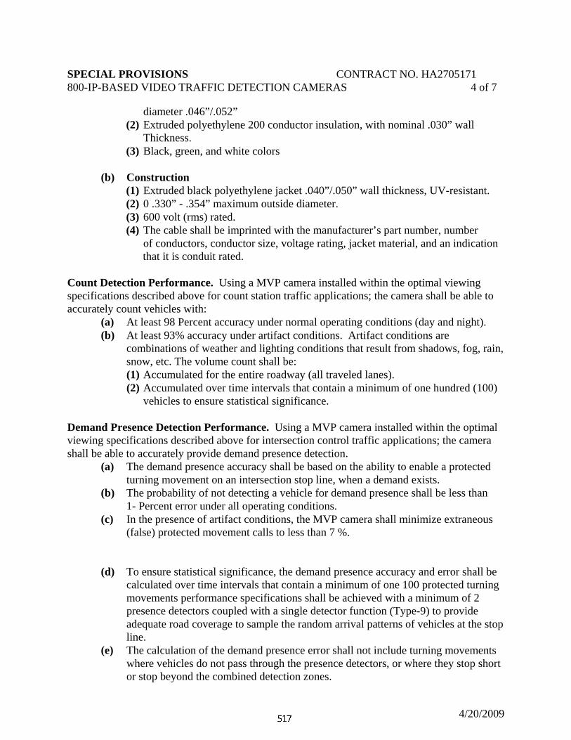
SPECIAL PROVISIONS CONTRACT NO. HA2705171 800-IP-BASED VIDEO TRAFFIC DETECTION CAMERAS 4 of 7
4/20/2009
diameter .046”/.052” (2) Extruded polyethylene 200 conductor insulation, with nominal .030” wall
Thickness. (3) Black, green, and white colors
(b) Construction
(1) Extruded black polyethylene jacket .040”/.050” wall thickness, UV-resistant. (2) 0 .330” - .354” maximum outside diameter. (3) 600 volt (rms) rated. (4) The cable shall be imprinted with the manufacturer’s part number, number
of conductors, conductor size, voltage rating, jacket material, and an indication that it is conduit rated.
Count Detection Performance. Using a MVP camera installed within the optimal viewing specifications described above for count station traffic applications; the camera shall be able to accurately count vehicles with: (a) At least 98 Percent accuracy under normal operating conditions (day and night). (b) At least 93% accuracy under artifact conditions. Artifact conditions are combinations of weather and lighting conditions that result from shadows, fog, rain, snow, etc. The volume count shall be: (1) Accumulated for the entire roadway (all traveled lanes). (2) Accumulated over time intervals that contain a minimum of one hundred (100) vehicles to ensure statistical significance. Demand Presence Detection Performance. Using a MVP camera installed within the optimal viewing specifications described above for intersection control traffic applications; the camera shall be able to accurately provide demand presence detection.
(a) The demand presence accuracy shall be based on the ability to enable a protected turning movement on an intersection stop line, when a demand exists.
(b) The probability of not detecting a vehicle for demand presence shall be less than 1- Percent error under all operating conditions.
(c) In the presence of artifact conditions, the MVP camera shall minimize extraneous (false) protected movement calls to less than 7 %.
(d) To ensure statistical significance, the demand presence accuracy and error shall be
calculated over time intervals that contain a minimum of one 100 protected turning movements performance specifications shall be achieved with a minimum of 2 presence detectors coupled with a single detector function (Type-9) to provide adequate road coverage to sample the random arrival patterns of vehicles at the stop line.
(e) The calculation of the demand presence error shall not include turning movements where vehicles do not pass through the presence detectors, or where they stop short or stop beyond the combined detection zones.
SPECIAL PROVISIONS CONTRACT NO. HA2705171 800-IP-BASED VIDEO TRAFFIC DETECTION CAMERAS 5 of 7
4/20/2009
Speed Detection Performance. The MVP shall accurately measure average (arithmetic mean) speed of multiple vehicles with more than 97% accuracy under all operating conditions for approaching and receding traffic.
(a) The average speed measurement will include a minimum of 100 vehicles in the sample to ensure statistical significance. (b) Optimal speed detection performance requires that camera location conform to the
specifications described above for count station traffic applications with the exception that the camera must be higher than 13 m (40) feet.
(c) The MVP will accurately measure individual vehicle speeds with more than 94% accuracy under all operating conditions for vehicles approaching the camera (viewing the front end of vehicles), and more than 90% accuracy for vehicles receding from the camera (viewing the rear end of vehicles).
(d) These specifications will apply to vehicles that travel through both the count and Speed Detector pair and will not include partial detection situations created by lane-changing maneuvers. (e) To ensure statistical significance, the average speed accuracy and error will be
calculated over time intervals that contain a minimum of one hundred vehicles.
Modular Cabinet Interface Unit (Access Point). The modular cabinet interface unit shall be furnished and installed by the ADMINISTRATION. This section is for reference only.
The modular cabinet interface unit shall communicate directly with up to eight (8) MVP cameras and shall comply with the form factor and electrical characteristics to plug directly into a NEMA type C or D detector rack providing up to thirty-two (32) inputs and sixty-four (64) outputs or a 170 input file rack providing up to sixteen (16) contact closure inputs and twenty-four (24) contact closure outputs to a traffic signal controller.
(a) Additional Features. (1) Easy IP-addressable Ethernet connectivity using RJ-45 connectors. (2) USB 2.0 connector for a USB mouse.
(3) Provides PAL or NTSC analog video output for MPEG-4 streaming digital
video. (4) Detector rack or shelf mount installation (5) 1500 volts RMS isolation between rack logic ground and street wiring. (6) Emulates the function of up to 4 TS2 Bus Interface Units (BIU) (7) Self diagnostics on power-up (8) High-energy transient protection
(b) Power: 12 to 24 VDC, 11W maximum (c) Environmental
(1) Temperature: -34° C to +74° C (-29° F to +165° F) (2) Relative Humidity: 0 to 95 Percent
SPECIAL PROVISIONS CONTRACT NO. HA2705171 800-IP-BASED VIDEO TRAFFIC DETECTION CAMERAS 6 of 7
4/20/2009
(d) Dimensions and Weight (1) 114 mm H x 59 mm W x 175 mm L
(4.5 in H x 2.34 in W x 6.9 in L) (2) Weight: 0.5 lb.
(e) Complies with: CE EN 55022, EN 61000-6-1 FCC Part 15, Class A
Communications Interface Panel. The communications interface panel shall be furnished and installed by the ADMINISTRATION. This section is for reference only. The communications interface panel shall have the following features:
(a) Four (4) sets of three (3) electrical terminations for three-wire cables for powering up to eight (8) MVP cameras.
(b) High-energy transient protection to electrically protect the modular cabinet Interface unit and connected MVP cameras.
(c) Single-point Ethernet connectivity via RJ45 connector for communication to and between the modular cabinet interface module and the MVP cameras.
(d) Predefined wire termination blocks for MVP power connections. (e) A Broadband-Over-Power-Line (BPL) transceiver that supports up to 10 MB/s
inter-device communications. (f) An Interface connector to cable directly to the modular cabinet interface unit. (g) The option of using either 110/220 VAC 50/60 Hz power. (h) Fuse protection using SLO-BLO, ½ amp fuses.
Installation and Training. The supplier of the video detection camera shall supervise the installation and testing of the video detection camera and any optional computer equipment. Warranty, Maintenance and Support . The video detection camera shall be warranted by its supplier for a minimum of two (2) years. Documentation. The equipment supplier shall deliver a CD containing operating manuals, service manuals, and maintenance instructions for the video traffic detection camera being supplied to the Administration’s Office of Traffic & Safety, Signal Operations Division, located at 7491 Connelley Drive, Hanover, Maryland 21076. The phone number is 410-787-7650.
MEASUREMENT AND PAYMENT. Video traffic detection cameras will be measured and paid for at the contract unit price per each. The payment will be full compensation for furnishing and installing the video traffic detection camera, equipment specified, all mounting hardware, including camera support to structure, 3-conductor cable from the camera to the controller cabinet, labor, and all incidentals necessary to complete this work.
NOTE: The Communications Interface Panel, Modular Cabinet Interface Unit, and all other cabinet equipment will be furnished and installed by the ADMINISTRATION.

SPECIAL PROVISIONS CONTRACT NO. HA2705171 800-IP-BASED VIDEO TRAFFIC DETECTION CAMERAS 7 of 7
4/20/2009

SPECIAL PROVISIONS CONTRACT NO. HA270A21 UTILITY CONNECTIONS
10-31-08
1 of 2 CATEGORY 800 TRAFFIC UTILITY CONNECTIONS, AND UTILITY STAKEOUT
DESCRIPTION. This work shall consist of utility connections, and utility stakeout, as specified in the Contract Documents or as directed by the Engineer.
MATERIALS.
Disconnect Switches and Utility Connections 950.13.10
CONSTRUCTION. Arrange a meeting with the utility company representatives, Traffic Operations Division representatives, the Engineer and the District Utility Engineer as specified in the Contract Documents to establish a schedule for utility connections before any equipment or material is installed.
Do not disconnect, de-energize, reconnect, tamper with, or otherwise handle any of a utility company’s facilities. The Contractor shall be responsible for the utility service connections to the utility company’s supplied point of service.
Make the necessary arrangements with the utility companies to insure having needed utilities available at the time of turn on. Any utility energization, connection or disconnection delays will not be considered a valid reason for any work time extension claim. Difficulties in securing utility company services are to be reported to the Engineer at the earliest possible time.
Utility Stakeout. Notify the appropriate agencies listed in the Contract Documents, and those listed below a minimum of 72 hours (excluding weekends and holidays) prior to the Contractor’s anticipated beginning of any underground work.
a) In Montgomery County, request Montgomery County (240-777-2100) to stakeout their ITS and signal facilities.
b) Request the Statewide Operations Center (800-543-2515) to stake out SHA fibreoptic and communication cables.
c) Request the Communications Division (410-747-8590 ) to stake out ITS devices.
d) Request appropriate RME to stake out lighting.
e) Notify the Hanover Complex Signal Shop (410-787-7652) of all requests for signal and ITS stakeouts.

SPECIAL PROVISIONS CONTRACT NO. HA270A21 UTILITY CONNECTIONS
10-31-08
2 of 2
Plan the work to minimize interference with any existing traffic control devices. Existing equipment shall remain in it’s original condition until the new equipment has been completed, satisfactorily tested and its operation accepted by the Engineer.
MEASUREMENT AND PAYMENT. Utility Connection. Utility Service Equipment connections will be measured and paid for as specified in 807.04.01.
All utility company energization, connection or disconnection costs will be the responsibility of the Administration.
Utility Stakeout. Utility Stakeout will not be measured but the cost will be incidental to other pertinent items specified in the Contract Documents.

SPECIAL PROVISIONS CONTRACT NO. HA270A21 SECTION 802-GALVANIZED STEEL BEAM SIGN POSTS
11/03/08
1 of 1
CATEGORY 800 TRAFFIC
SECTION 802-GALVANIZED STEEL BEAM SIGN POSTS 623 802.02 MATERIALS
ADD: The following:
Structural Tubing A500, Grade B DELETE: Delete the first sentence in section 802.04 INSERT: The following:
Galvanized Steel Beam Sign Posts and Structural Tubing Sign Posts will be measured and paid for at the Contract unit price per linear foot for the various sizes of posts specified in the Contract Documents.

SPECIAL PROVISIONS CONTRACT NO. HA270A21 808-LIGHTING STRUCTURES
11-04-08
1 of 4 CATEGORY 800
TRAFFIC
SECTION 808-LIGHTING STRUCTURES
634 808.01 DESCRIPTION: DELETE: The paragraph in its entirety INSERT: The following. Furnish and install low level steel and aluminum lighting poles, bracket arms and fittings, and steel high mast lighting structures as specified in the Contract Documents or as directed by the Engineer. Concrete foundations are excluded.
808.02 MATERIALS: ADD: The following at the end of the list of materials. High mast shafts A595 Grade A Steel base plates and other structural steel A709 Grade 50 including Charpy V Notch requirements for Zone 2 Galvanization for hardware A153 Design High Mast Lighting Structures for mounting a head frame and lowering device assemblies. Design shall be in accordance with the 2001 AASHTO “Standard Specifications for Structural Supports for Highway Signs, Luminaires and Traffic Signals” and as indicated in contract documents. Structures shall include a reinforced handhole with a hinged handhole cover that shall be padlocked. Padlocks shall be keyed alike and shall be in accordance with the standards of the State Highway Administration. Contractor’s and/or fabricators name and logo shall not be placed on the lighting standards. Marked numbers shall appear on surface areas that will not be visible to traffic after erection. The shaft of High Mast Lighting Structures shall be made of tapered sections that telescope each other. Shaft diameters and tapers shall be as shown in the Contract Documents.

SPECIAL PROVISIONS CONTRACT NO. HA270A21 808-LIGHTING STRUCTURES
11-04-08
2 of 4 Telescoping sections shall be forced into place and be thoroughly wedged to produce the required engagement as listed on the Contract Documents. The Contractor shall submit erection plans and procedures to the Engineer for approval prior to installation of the High Mast Lighting Structure on location. Structures shall be installed with all internal wiring, attachments, and hoist cable assemblies in place and erected in accordance with the manufacturers recommendations. Structures shall be erected plumb. Plumb shall be checked using two transits set 90 degrees apart. Plumbing shall not be done in full sun to avoid deflection from radiant heat. Tolerance for plumb shall be 3 inches per 100 feet. Nuts shall be tightened to secure the structure in place. The loading, transporting and unloading of all parts shall be conducted to avoid injury and deformation of the metal. Areas damaged in transport or erection shall be repaired to the satisfaction of the Engineer. During the erection process, all materials shall be handled carefully and shall be stored on platform, skids, or other supports to keep parts off of the ground. The steel shall be kept free and clean from all foreign materials, particularly grease, oil, concrete, chock marks and dirt that may effect the natural oxidation of the steel. All structures shall be treated with care given to any product such that the finished surface remains as prepared in the fabrication shop. Any foreign matter that gets on the surface after galvanizing shall be removed as soon as possible and the soiled areas shall be returned to the conditions as listed above. Luminaire Head Assembly and Lowering Gear All structural and sheet metal parts shall be of zinc coated meeting the same structural requirements as the shaft. All bolts, nuts, washers, and lock washers shall be stainless steel. All luminaires shall be as stated in Section 806. The luminaire support frame shall be a steel ring integrally welded together and shall serve as a raceway for electrical wiring to the luminaires. The frame shall be suspended from and held in place by three stainless steel suspension cables of 3/16-inch minimum diameter. These cables shall be permanently affixed through a weight equalizing spring assembly to a single sustaining raising-lowering winch. The three suspension cables securing the frame shall pass over pulleys of non-corrosive material fitted with permanently lubricated ball bearings, cable guides and cable retainers. The suspension cables, weight equalizing spring assembly, and winch shall be installed within the shaft. A means shall be provided within the shaft to prevent the three suspension cables from fouling the power cable when raising and lowering the luminaire frame. The raising-lowering winch shall be suitable for manual as well as power driven operation. The downward travel of the lowering ring shall be sufficient to lower the lights to a position 5 feet above the base of the standard. Cushioned bumpers, or similar devices, shall be provided to absorb any shock resulting from contact between the lowering ring and pole during the up and down travel of the ring.

SPECIAL PROVISIONS CONTRACT NO. HA270A21 808-LIGHTING STRUCTURES
11-04-08
3 of 4 The lowering gear shall include a braking mechanism to prevent the luminaires from lowering without intentional operation of the winch. Latching Mechanism Each pole shall be provided with a latching mechanism that shall secure the suspension cables and minimize the stress on the winch cable and winch. The latching mechanism shall be completely accessible through the access door in the pole base. Additionally, a safety chain shall be provided capable of supporting the full weight of the luminaires and lowering equipment in the event of a failure of the latching mechanism. Electric Drive Assembly The electric drive assembly shall be a reversible continuous heavy duty electric drill with a 240 volt universal motor, a torque clutch, a remote control station with a 35 foot long extension cord, and a mounting bracket to firmly hold the drive unit in place when it is engaged with the hoisting winch. The electric drive assembly shall be provided with a socket to fit the ½ inch square input shaft of the winch. The drill shall produce the necessary torque to raise and lower the lowering ring with six luminaires through 10 successive cycles with no more than one minute between each cycle and without producing excess heating or overloading of the electric drive assembly. Provide a remote control for the electric drive assembly that allows the operator to control the raising and lowering of the luminaires while standing clear of the luminaire assembly and pole. The Electric Drive Assembly shall raise or lower the luminaires at a rate of not less than 10 feet per minute. As part of the electric drive assembly a transformer shall be provided to convert from the operating voltage of the luminaires to 240 volts for the electric drive assembly. The transformer shall have a 10 foot long 3/C, 600 volt, heavy duty portable cable with plug to match the drive unit receptacle in the base of the lighting mast, and a grounded weatherproof receptacle on the load side to supply the drive unit motor. All outlets shall be easily accessible from the access door. Electric Drive Assemblies shall be turned over to the Engineer at the completion of construction. Electrical Equipment for High Mast Lighting Structures A. Terminal boards shall be rated 30 amperes, 600 volts, fabricated from non-tracking
materials and equipped with covers. They shall be similar and equal to General Electric Company Type EB-5, Square D Class 9080, Type S or Westinghouse Type TBA.
B. Plugs and receptacles shall be heavy duty, weather resistant, rated 20 amperes, 480 volts
AC, grounded type. Receptacles shall have weatherproof cap and mating plug. C. Junction boxes shall be galvanized cast iron with hubs and hinged covers.
SPECIAL PROVISIONS CONTRACT NO. HA270A21 808-LIGHTING STRUCTURES
11-04-08
4 of 4 Testing All electrical equipment shall be tested and its operation shall be demonstrated to the Engineer. Upon completion of erection and following the installation of the luminaires and all electrical components, the lowering device shall be tested on each standard in the presence of the Engineer. The test shall consist of two complete operations, conducted on two different days, starting with the unlatching or unlocking, lowering the head assembly to its minimum height, raising the head assembly back to its installed height, and latching or locking. The test shall be considered satisfactory when 80 percent of the operations require no second attempts to complete any function and the remaining 20 percent of the operations require no more than three attempts to complete any function. Should the equipment fail this test, the contractor shall adjust or modify those components causing the failure and repeat the tests from the beginning. 808.03 CONSTRUCTION ADD: The following. 808.03.01 Fabrication, welding and non-destructive shall conform to the contract documents and AASHTO Highway Signs, Luminaries and Traffic Signals 4th Edition 2001, unless otherwise specified. 808.04 MEASUREMENT AND PAYMENT ADD: The following. 808.04.05 High Mast Light Structure, Luminaires & Lowering Gear will be measured and paid for at the contract unit price per each light pole furnished and installed. The payment will be full compensation for the High Mast Lighting Pole, the luminaire head assembly and lowering gear, all electrical equipment including internal wiring, luminaires, testing and for all material, labor, equipment, tools, and incidentals necessary to complete the work. 808.04.06 Electric Drive Assemblies will be measured at the contract unit price per each. The payment will be full compensation for electric drill, mounting bracket, transformers, remote controls, testing, and for all material, labor, equipment, tools, and incidentals necessary to complete the work.

SPECIAL PROVISIONS CONTRACT NO. HA270A21 1 of 1
9-30-08
CATEGORY 800
TRAFFIC
SECTION 810 ⎯ ELECTRICAL CABLE, WIRE, AND CONNECTORS
810.02 MATERIALS. ADD: Cable Duct End Seals shall consist of a one-piece heat shrinkable device designed to provide a waterproof seal around the cable duct and each individual cable. The Cable Duct End Seal shall have separate entranceways for each cable, and shall hold the cables apart when applied. 810.03. CONSTRUCTION. 810.03.03 Preassembled Cable Duct Delete: The second paragraph beginning “After backfilling…” in it’s entirety. INSERT: The following. After backfilling demonstrate that the conductors move freely within the duct by pulling the conductors out a minimum of length of 2 ft. Pulling Tension shall conform to 810.03.02. The cable shall be then pulled to it’s original position, and the Cable Duct End Seals installed. After installation of the Cable Duct End Seals, but prior to installing connector kits or splices, the electrical circuit testing shall be performed as specified in 820.03.02 (b) and the results recorded. The contractor shall record the length of cable, locations of both ends of the cable duct, and the insulation resistance on a form acceptable to the Engineer, and forward the form to the Engineer. 823.04 MEASUREMENT AND PAYMENT. 810.04.01 ADD: Preassembled Cable Duct that has not had the required electrical tests performed and reported to the engineer will not be measured or paid for. ADD: 810.04.03 Cable Duct End Seals shall be measured and paid for at the contract unit price per each.

SPECIAL PROVISIONS CONTRACT NO. HA270A21 814-SIGNAL HEADS
10-31-08
1 of 1
CATEGORY 800 TRAFFIC SECTION 814—SIGNAL HEADS 814.01 DESCRIPTION.
641 ADD: The following after the first paragraph. Furnish and install Aluminum and Polycarbonate 8-in. and 12-in. vehicle traffic control signal heads
and hardware with LED Green, Yellow, and Red indications, as specified in the Contract Documents or as directed by the Engineer. All signal housing shall have a black face and yellow housing. 814.02 MATERIALS. ADD: The following to the end of the list of materials.
LED Traffic Signal Modules “Section 800 LED TRAFFIC SIGNAL MODULES”
ALL Red and Green Traffic Signals COMAR 14.26.03 (LED or Incandescent) (Certification of compliance with Maryland Energy Efficiency Standards) 814.04 MEASUREMENT AND PAYMENT. ADD: The following after the first paragraph. Aluminum and Polycarbonate LED Signal heads will be measured and paid for at the Contract unit price per each section of signal head type and size as specified in the Contract Documents. The LED signal heads will have the LED module fitted into the housing assembly. The payment will be full compensation for the housing, LED signal module, and, mounting hardware, assembly, and for all material, labor, equipment, tools, and incidentals necessary to complete the work.

SPECIAL PROVISIONS CONTRACT NO. HA270A21 819-STEEL SPAN WIRE
10-31-08
1 of 1 CATEGORY 800
TRAFFIC
SECTION 819 ⎯ STEEL SPAN WIRE 645 819.01 DESCRIPTION.
CHANGE: In the second line the terminology "signal head or sign mountings, interconnect runs, or for tethering purposes" to read "signal head or sign mountings, interconnect runs, backguying, overhead communications cable pole to pole guying, overhead communications cable slack, spans overhead communications cable, false dead ends or for tethering purposes"
819.03 CONSTRUCTION.
CHANGE: In the first line the terminology “Attach the span wire to poles” to read "Attach the span wire to signal structures“.
ADD: After the third paragraph: “Overhead communications cable steel span wire back guying, pole to pole guying, false dead ending and slack spans shall be installed on all utility owned poles in accordance with the utility pole owner’s requirements. Ram head type guy hooks shall be installed for overhead communications cable steel span wire back guying, pole to pole guying, false dead ending and slack spans on all utility owned poles. Wrap type guy grips shall be used to terminate the ends of overhead communications cable steel span wire back guying, pole to pole guying, false dead ending and slack spans. Strandvise devices shall not be used to terminate the steel span wire ends of overhead communications cable steel span wire back guying, pole to pole guying, false dead ending and slack spans.”

SPECIAL PROVISIONS CONTRACT NO. HA270A21 822-REMOVE AND RELOCATE SIGNS
10-31-08
1 of 1 CATEGORY 800
TRAFFIC
SECTION 822-REMOVE AND RELOCATE EXISTING SIGNS AND SIGN STRUCTURES
650 DELETE: 822.04.02 in its entirety INSERT: The following:
822.04.02 Remove Signs From Existing Overhead Structure will be measured and paid for at the Contract unit price per square foot area of the sign. Removal of sign and sign luminaire supports, luminaires, catwalks, conduit and cable will not be measured but the cost will be incidental to the Contract unit price for removing the signs.

SPECIAL PROVISIONS INSERT CONTRACT NO.HA2705171 900 — MATERIALS 1 of 4
03-03-10
CATEGORY 900 MATERIALS
655 ADD: The following after the last paragraph of 900.02 TECHNICIAN
QUALIFICATION REQUIREMENTS.
900.03 RECYCLED MATERIALS. 900.03.01 CERTIFICATION. All recycled or rehandled material furnished or supplied for use may require testing and certification to ensure compliance with all State and local applicable environmental and EPA regulations. The required testing may include, but not be limited to, the EPA Toxicity Characteristic Leaching Procedure (TCLP) or its successor. Provide testing and certification for all recycled materials at no additional cost to the Administration. Evaluation and interpretation of the test data will be made by an OMT Quality Assurance Manager. The above requirements do not preclude the normal materials acceptance process, and the recycled material shall meet all applicable specifications. EPA regulations governing the use of the material, certified test results, and material safety data sheets shall accompany the source of supply letter and sample submitted for approval. Refer to the Contract Documents for recycled materials not covered by this specification. 900.03.02 RECLAIMED/RECYCLED CONCRETE (RC). Usage. Use RC for the following with written approval:
(a) Graded Aggregate Base (GAB). (b) Common, Select, or Modified Borrow:
(1) At least 2 ft above saturated soil or groundwater conditions, (2) At least 100 ft from surface waters (streams, creeks, or rivers), (3) At least 3 ft from exposed metal surfaces, and, (4) At least 3 ft from geotextile.
(c) Riprap.
Do not use RC as Capping Borrow nor as aggregate for the following:
(a) Portland cement concrete.
(b) Hot mix asphalt.

SPECIAL PROVISIONS INSERT CONTRACT NO.HA2705171 900 — MATERIALS 2 of 4
03-03-10
(c) Drainage systems. (d) Mechanically stabilized earth (MSE) systems:
(1) MSE walls. (2) Reinforced soil slopes (RSS). (3) Reinforced earth slopes (RES).
(e) In embankment construction as follows:
(1) Within 1 ft of the top surface of any area to be vegetated. (2) Within 2 ft of saturated soil or groundwater conditions. (3) Within 100 ft of any surface water course (streams, creeks, or rivers). (4) Within 3 ft of any metal pipe or shoring.
(f) Under pervious or porous surfaces.
Grading Requirements. The grading requirements for the use of RC are:
(a) Table 901 A when used as GAB or for any other application within the pavement structure. (b) 204.02 when used in embankment construction. (c) 916.01 when used as Borrow material. (d) 901.02.01 when used as riprap.
RC shall not contain more then 5 percent brick and hot mixed asphalt material by mass except when used as Common Borrow. pH Requirements. The pH shall be less than 12.0 for all applications. RC usage shall not cause water leaving the site to exceed a pH of 8.5. RC may be blended with natural materials to control the pH. RC used as GAB requires daily testing to monitor the pH, and as directed. Quality Control. The producer shall submit a Quality Control Plan and obtain approval prior to production. The plan shall include, but not be limited to, the operational techniques and procedures proposed to produce the RC product. Quality control includes the sampling and testing performed to validate the quality of the product during production operations.

SPECIAL PROVISIONS INSERT CONTRACT NO.HA2705171 900 — MATERIALS 3 of 4
03-03-10
Quality Assurance. OMT Quality Assurance personnel will perform quality assurance inspection, sampling, and testing at the point of processing/reclamation. Additional inspection and compaction control will be performed by the Project Engineer. 900.03.03 RECYCLED ASPHALT PAVEMENT (RAP). Usage. Use RAP for Common, Select, Capping, or Modified Borrow. Do not use RAP as aggregate for the following:
(a) Graded Aggregate Base (GAB). (b) Portland cement concrete. (c) Drainage systems. (d) Embankment construction.
(1) Within 1 ft of the top surface of any area to be vegetated. Refer to MSMT 412 and M 323 for the use of RAP in hot mix asphalt mixes. Grading Requirements. The grading requirements for the use of RAP are:
(a) 204.02 when used in embankment construction, (b) 916.01 when used as Borrow material, (c) 901.02.01 when used as riprap.
Quality Control. Create a captive stockpile for storing the RAP prior to use. Create a new captive stockpile and take new acceptance samples for gradation approval whenever the source of the RAP changes. Quality Assurance. OMT Quality Assurance personnel will sample and test the RAP stockpiles to ensure that they meet the above gradation requirements. The completed test results will be reviewed by the OMT Soils and Aggregate Division for approval. Construction of Control Test Strip. The location, equipment, and methods used to construct the control test strip shall be as directed; prior to approval. The equipment and methods used to construct the control test strip shall be the same as those used in subsequent construction. Place and test the control test strip when the RAP is 32°F or higher to establish the maximum density. RAP is temperature sensitive, which may affect the density.

SPECIAL PROVISIONS INSERT CONTRACT NO.HA2705171 900 — MATERIALS 4 of 4
03-03-10
Construct the control test strip that shall be at least 100 ft long, 12 ft wide and a maximum compacted lift thickness of 6 in. Prepare the subgrade for the control test strip in accordance with 204.03.07. Do not construct the control strip, or perform any subsequent construction, on frozen subgrade. Compact the RAP for the control test strip with one pass of the roller. Measure the density after one pass with a nuclear density gauge (backscatter method) at the frequency for capping material at five random locations distributed across the length and width of the control test strip, as directed. Record the measurements and mark the locations for future reference. Compact the RAP for the control test strip with a second pass of the roller. Measure and record the density again at the exact locations previously tested and as described above. Prepare a plot of density versus the number of roller passes. Continue this process until the maximum dry density of the control strip is established. There should be no drop in average density during construction of the control test strip for each lift. A drop in the average density of greater than 2 pcf during construction of the control test strip is an indication that the material is not properly compacting, and a new test strip shall be constructed. The Project Engineer may require the Contractor to cut into the control test strip for visual inspection. All material, labor, equipment, tools, and incidentals necessary to provide an approved control test strip shall be at no additional cost to the Administration. Compaction Control. Use the roller pattern and number of passes determined from the construction of the test strip to compact the RAP for production placement. The density of the RAP compacted for production work shall be at least 97 percent of the maximum density obtained from the control test strip. Recheck the density of the production work if it is less than 97 percent of the maximum density obtained from the control test strip. Construct a new control test strip if the second density does not meet the 97 percent requirement. Construct a new control test strip if the measured density of the compacted RAP for production work exceeds 105 percent. Establish one rolling pattern to achieve maximum density for each use based on the control test strips. Samples or results produced prior to the construction of any new stockpiles will not be considered.
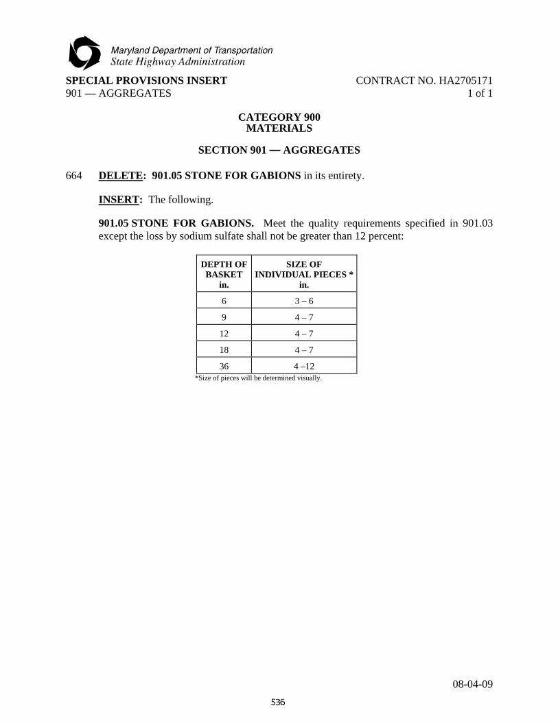
SPECIAL PROVISIONS INSERT CONTRACT NO. HA2705171 901 — AGGREGATES 1 of 1
08-04-09
CATEGORY 900
MATERIALS
SECTION 901 — AGGREGATES 664 DELETE: 901.05 STONE FOR GABIONS in its entirety.
INSERT: The following.
901.05 STONE FOR GABIONS. Meet the quality requirements specified in 901.03 except the loss by sodium sulfate shall not be greater than 12 percent:
DEPTH OF
BASKET in.
SIZE OF INDIVIDUAL PIECES *
in.
6 3 – 6
9 4 – 7
12 4 – 7
18 4 – 7
36 4 –12 *Size of pieces will be determined visually.

SPECIAL PROVISIONS INSERT CONTRACT NO. HA2705171 902-PORTLAND CEMENT CONCRETE 1 of 15
10-31-08
CATEGORY 900 MATERIALS
665 DELETE: SECTION 902 — PORTLAND CEMENT CONCRETE AND
RELATED PRODUCTS in its entirety. INSERT: The following.
SECTION 902 — PORTLAND CEMENT CONCRETE AND RELATED PRODUCTS 902.01 STORAGE. Storage of materials shall conform to the Contract Documents and as directed by the Engineer. 902.02 CERTIFICATION OF PORTLAND CEMENT AND BLENDED HYDRAULIC CEMENT. The manufacturer shall furnish certification as specified in TC-1.02. The certification shall also include: (a) The mill shall report its quality control procedures, and submit a new report whenever there
is a procedural change. (b) The mill's control laboratory shall be inspected by the Cement and Concrete Reference
Laboratory of the National Institute of Standards and Technology on their regularly scheduled visits. The Engineer shall be provided with copies of the reports of these inspections along with an account of the action taken to correct cited deficiencies.
(c) Records of data accumulated by the quality control procedures shall be produced upon
request. (d) A certified document shall accompany each shipment stating that the contents conform to
all applicable requirements. Additionally, the document shall show the producer's name, mill location, carrier number, date loaded, weight contained in carrier, silo number, consignee, destination, Contract number, and type of cement. The signature and title of the signer shall be shown on the document.
(e) The mill shall, upon request, supply certified chemical and physical test values that can be
associated with any sample representing cement drawn from a particular silo on a given date.
(f) Acceptance of cement by certification will be terminated if test results differ from mill
results by more than the precision limits given in the test method. The acceptance procedure will then revert to storage testing and approval prior to shipment.
902.03 HYDRAULIC CEMENT. 902.03.01 Portland Cement. M 85, with the fineness and the time of setting determined using T 153 and T 131, respectively.

SPECIAL PROVISIONS INSERT CONTRACT NO. HA2705171 902-PORTLAND CEMENT CONCRETE 2 of 15
10-31-08
902.03.02 Ground Iron Blast Furnace Slag. M 302, Grade 100 or 120. The Contractor may request to substitute a maximum of 50 percent of the weight of cement with ground iron blast furnace slag. When ground iron blast furnace slag is used, the minimum cement factor and water/cement ratio will be determined on the basis of the combined weight of the portland cement and ground iron blast furnace slag. When ground iron blast furnace slag is used to control alkali silica reactivity, see Table 902 B for percentage. 902.04 BLENDED HYDRAULIC CEMENT. M 240, Type I (PM) or a Type IP containing 15 to 25 percent pozzolan by weight of cement. Maximum loss on ignition is 3.0 percent. Do not use ground iron blast furnace slag for blending. The requirement for a manufacturer’s written statement of the chemical composition is waived. 902.05 MASONRY CEMENT. C 91, except the water retention and staining tests are waived. 902.06 CONCRETE ADMIXTURES. Do not use concrete admixtures that contribute more than 200 ppm of chlorides based on the cement content when tested per MSMT 610. Use only prequalified admixtures. Do not use pozzolan and Type I (PM) or Type IP cement in the same mix. Since the strength gains are delayed with these materials, a longer period of time may be required for curing and form removal. 902.06.01 Air Entraining Admixtures. M 154. 902.06.02 Chemical Admixtures. M 194, Type A, D, or nonchloride C. 902.06.03 High Range Water Reducing Admixtures. M 194, except that it shall be a liquid, the water content shall be a maximum of 85 percent of that of the control, and the durability factor shall be a minimum of 90. Use Type F for early strength, which shall produce a minimum compressive strength in 12 hours of 180 percent of that of the control. Use Type G when early strength is not specified. The manufacturer shall furnish certification as specified in TC-1.02. The certification shall include curves indicating the fluid ounces of admixture per 100 lb of cement as related to water reduction and strength gain for 12 hours when used with a minimum cement factor of 700 lb. 902.06.04 Pozzolans. The use of pozzolans may be requested to control alkali silica reactivity or for other reasons. When a pozzolan is used, determine the minimum cement factor and water/cement ratio on the basis of the combined weight cement and pozzolan. See Table 902 B for percentage of fly ash, and microsilica. (a) Fly Ash. M 295, pozzolan Class C or F, except that the maximum permissible moisture
content shall be 1.0 percent, and when used in concrete Mix Nos. 3 and 6 the maximum loss on ignition 3.0 percent.
(b) Microsilica. C 1240, except that the oversize requirement is waived.

SPECIAL PROVISIONS INSERT CONTRACT NO. HA2705171 902-PORTLAND CEMENT CONCRETE 3 of 15
10-31-08
902.06.05 Corrosion Inhibitors. Corrosion inhibitors shall be calcium nitrite based and contain a minimum of 30 percent active ingredients by mass. The gallonage of corrosion inhibitor used in the concrete mixture shall be included as water when determining the water/cementitious materials ratio. 902.07 PORTLAND CEMENT CONCRETE CURING MATERIALS. Use burlap cloth, sheet materials, liquid membrane forming compounds, or cotton mats. 902.07.01 Burlap. M 182, Class 1, 2, or 3. 902.07.02 Sheet Materials. M 171 with the following exceptions: (a) White Opaque Burlap Polyethylene Sheeting. Tensile strength and elongation
requirements are waived. Use sheeting having a finished product weight of not less than 10 oz/yd2.
(b) White Opaque Polyethylene Backed Nonwoven Fabric. 902.07.02(a), with the
thickness requirement waived. Use material having a finished product weight of not less than 5 oz/yd2.
(c) White Opaque Polyethylene Film. Tensile strength and elongation requirements are
waived. 902.07.03 Liquid Membrane. M 148. Field control testing of the white pigmented curing compounds is on the basis of weight per gallon. The samples shall not deviate more than ± 0.3 lb/gal from the original source sample. 902.07.04 Cotton Mats. Cotton mats consist of a filling material of cotton bats or bats covered with unsized cloth and tufted or stitched to maintain the shape and stability of the unit under job conditions of handling. Use coverings of either cotton cloth, burlap or jute having the following properties: (a) Cotton cloth covering shall weigh not less than 6.0 oz/yd2 and have an average of not less
than 32 threads/in. of warp and not less than 28 threads/in. of filling. Use raw cotton, cotton comber waste, cotton card strip waste, or combinations thereof as the raw material used in the manufacture of the cotton cloth.
(b) Burlap or jute covering for cotton mats shall weigh not less than 6.4 oz/yd2 and shall have
not less than of 8 threads/in. of warp and not less than 8 threads/in. of filling. Use the grade known commercially as "firsts" and they shall be free from avoidable imperfections in manufacture and from defects or blemishes affecting the serviceability.
Use a cotton bat, or bats made of raw cotton, cotton waste, cotton linters, or combinations thereof, as the filling material for the mats. Mats shall weigh not less than 12 oz/yd2.

SPECIAL PROVISIONS INSERT CONTRACT NO. HA2705171 902-PORTLAND CEMENT CONCRETE 4 of 15
10-31-08
902.08 FORM RELEASE COMPOUNDS. Use form release compounds that effectively prevent the bond of the concrete to the forms. Form release compounds shall not cause discoloration of the concrete or adversely affect the quality or rate of hardening at the interface of the forms. The flash point of the form release compound shall not be less than 100 F when tested per T 73. 902.09 PARAFFIN WAX. Use clear paraffin wax for use as a bond breaker for concrete. The flash point shall not be less than 380 F when tested under D 92. 902.10 PORTLAND CEMENT CONCRETE. Section 915 and as specified herein. 902.10.01 Proportioning. Prior to the start of construction, submit to the AME the source and proportions of materials to be used for each concrete mix. The mixture shall meet 902.10.03. The concrete, with the exception of water and chemical admixtures, shall be proportioned by weight. Water and chemical admixtures may be proportioned by volume or weight. The mix shall be uniform and workable. 902.10.02 Materials.
Coarse Aggregate 901.01 Fine Aggregate 901.01 Cement 902.03 and 902.04 Concrete Admixtures 902.06 Synthetic Fibers 902.15 Water 921.01
902.10.03 Portland Cement Concrete Mixtures.

SPECIAL PROVISIONS INSERT CONTRACT NO. HA2705171 902-PORTLAND CEMENT CONCRETE 5 of 15
10-31-08
The concrete mixes shall conform to the following:
TABLE 902 A
PORTLAND CEMENT CONCRETE MIXTURES
MIX NO. 28 DAY
SPECIFIED COMPRESSIVE
STRENGTH
psi
STANDARD DEVIATION
psi
CRITICAL
VALUE
psi
MIN
CEMENT FACTOR
lb/yd3
COARSE
AGGREGATE SIZE
M 43 / M 195
MAX WATER/ CEMENT
RATIO
by wt
SLUMP RANGE
in.
TOTAL
AIR CONTENT
%
CONCRETE
TEMPERATURE
F
1 2500 375 2430 455 57, 67 0.55 2 — 5 5 — 8 70 ± 20
2 3000 450 3010 530 57, 67 0.50 2 — 5 5 — 8 70 ± 20
3 3500 525 3600 580 57, 67 0.50 2 — 5 5 — 8 70 ± 20
4 3500 525 3600 615 57, 67 0.55 4 — 8 N/A 70 ± 20
5 3500 525 3600 580 7 0.50 2 — 5 5 — 8 70 ± 20
6 4500 675 4770 615 57, 67 0.45 2 — 5 5 — 8 65 ± 15
7 4200 630 4420 580 57 0.50 1½ — 3 5 — 8 70 ± 20
8 4000 600 4180 750 7 0.42 2 — 5 5 — 8 65 ± 15
9 3000 (a) N/A N/A 800 57, 67 0.45 4 — 8 5 — 8 70 ± 20
10 4500 675 4770 700 ¾” – No. 4 0.45 2 — 5 6 — 9 65 ± 15
11 4200 630 4420 — 57, 67 0.45 2 — 5 5 — 8 65 ± 15
12 4200 630 4420 — ¾” – No. 4 0.45 2 — 5 6 — 9 65 ± 15 Note 1: When concrete is exposed to water exceeding 15,000 ppm sodium chloride content, Type II cement shall be used. In
lieu ofType II cement, a Type I cement may be used in combined form with an amount of up to 50 percent replacement with ground iron blast furnace slag, or an amount of up to 25 percent replacement with Class F fly ash. The Contractor shall submit to the Engineer the proposed mix proportions and satisfactory test results per C 1012 showing a sulfate resistance expansion not exceeding 0.10 percent at 180 days
Note 2: The temperature of Mix No. 6 when used for other than superstructure work as defined in TC-1.02 shall be 70 ± 20 F. Note 3: Type A or D admixture shall be added to bridge, box culvert, and retaining wall concrete. Note 4: Nonchloride Type C admixtures may be used when approved by the Engineer. Note 5: Other Slump Requirements:
When a high range water reducing admixture Type F or Type G is specified, the slump shall be 4 to 8 in. When synthetic fibers are specified, the slump shall be 5 in. maximum. When concrete is to be placed by the slip form method, the slump shall be 2-1/2 in. maximum. When the absorption of the coarse aggregate is greater than 10 percent, the slump shall be 3 in. maximum.
Note 6: Mix 9 shall contain a Type F high range water reducing admixture. Note 7: Mix 10 and 12 shall be proportioned as specified in 211.2 of the ACI’s Recommended Practices for Selection
Proportions for. Structural Lightweight Concrete. The maximum average Density of Cured Concrete shall be 118 lb/ft3. Control testing for Density of Cured Concrete shall be two companion cylinders for each 100 yd3, or fraction thereof, as specified in M 195.
Note 8: Mix 11 and 12 shall also conform to all requirements as specified in Table 902 C. (a) Acceptance will be based on a minimum compressive strength of 3000 psi in 24 hours. Design approval will be given
based on trial batch obtaining a minimum compressive strength of 2500 psi in 12 hours. Testing shall conform to 902.10.08 except that cylinders shall remain in the molds until tests are conducted.
Coarse and fine aggregate having an expansion up to 0.10 percent when tested for alkali silica reactivity (ASR) MSMT 212 may be used without restriction. Aggregates having an expansion greater than 0.10 but less than 0.35 percent are considered reactive and may only be used when one of the options in table 902 B are employed. Those having an expansion of 0.35 percent and greater are prohibited.

SPECIAL PROVISIONS INSERT CONTRACT NO. HA2705171 902-PORTLAND CEMENT CONCRETE 6 of 15
10-31-08
TABLE 902 B
OPTION
ALKALI CONTENT
OF CEMENT
% max
REPLACE CEMENT WITH
SPECIFICATION MATERIAL % BY
WEIGHT
1 1.50 Class F Fly Ash 15 – 25 M 295
2 1.50 Ground Iron Blast Furnace Slag
25 – 50 M 302 Grade 100 or 120
3 1.50 Microsilica 5 – 7 C 1240
4 — Blended Cement (a) 100 M 240
5 0.60 (b) Low Alkali Cement 100 M 85
(a) Pozzolan content of 15 – 25 percent by weight of cement (b) For mix 9 used for Portland cement concrete pavement repairs; the maximum allowable percentage of
alkalies in Portland cement shall be 0.70.
When reactive aggregate is used, designate which option will be used to control the formation of the ASR gel. If an option other than option 5 in Table 902 B above is chosen, conduct tests per MSMT 212 using the reactive aggregate and the proposed cementitious material. The expansion test results shall not be greater than 0.10 percent. When more than one reactive aggregate is used in a concrete mix, each shall be tested individually and the maximum amount of pozzolan required to reduce the expansion of all the aggregates to 0.10 percent or less shall be used. Submit the aggregate source, test results, and the percent and type of replacement cement to the Engineer. The Engineer may withhold source approval pending verification testing.

SPECIAL PROVISIONS INSERT CONTRACT NO. HA2705171 902-PORTLAND CEMENT CONCRETE 7 of 15
10-31-08
TABLE 902 C
MIX PHYSICAL PROPERTIES
TEST PROPERTY TEST METHOD
SPECIFICATION LIMITS
Minimum Cementitious Materials Factor, lb/yd3 — 580
Maximum Content of Portland Cement, lb/yd3 — 550
Water/Cementitious Materials Ratio by Wt. — 0.45
Corrosion Inhibitor, gal/yd3 902.06.05 2.0
Synthetic Fibers, lb/yd3 902.15 1.5
Permeability of Field Concrete, moving average of three tests, coulombs max
T 277 Modified
2500
Permeability of Field Concrete, individual test, coulombs max
T 277 Modified
3000
Shrinkage at 28 days, microstrains C 157 400
Note 1: Only Type I or II Portland cement shall be used. Note 2: Mixes shall contain ground iron blast furnace slag, fly ash or microsilica.
Note 3: The water to cement ratio shall be based upon the total water to cementitious materials ratio. The gallonage of the corrosion inhibitor shall be included in the water/cementitious materials ratio.
Note 4: The permeability test value of field concrete shall be the average of two test specimens representing production concrete. Test specimens shall be molded on the project site in 4 x 8 in. molds conforming to M 205. Test specimens shall be handled under same conditions as compressive strength test specimens in conformance with C 31 for the first seven days. When seven days old, they shall be cured in a 100 F water bath for the remainder of the 28 day curing. The 28 day rapid chloride permeability of the specimens will be determined in conformance with T 277. Test for the geometry of test specimens will be waived.
Note 5: Shrinkage tests will be performed on trial mixes only. Note 6: High range water reducing admixture may be used except the water reducing requirements will be waived. Note 7: A sealer conforming to 902.12 shall be used on the finished surface.
902.10.04 Trial Batch. A trial batch shall be prepared to certify that each mix meets 902.10.05 and 902.10.06. Approval will be given when the test results meets the minimum required average strength. Make arrangements with the AME at least two weeks in advance, to have an authorized representative present during the batching and testing. Each trial batch shall consist of at least 3 yd3 of concrete. Supply all equipment, and labor required to produce the trial batches and conduct the required tests at no additional cost to the Administration. The AME may waive the requirement for a trial batch when past performance records show that the required average strength requirement has been met.
SPECIAL PROVISIONS INSERT CONTRACT NO. HA2705171 902-PORTLAND CEMENT CONCRETE 8 of 15
10-31-08
902.10.05 Design Required Average Strength.
Specified compressive strength,
fc´, psi
Required average compressive
strength, fcr´, psi
fc´ ≤ 5000
Use the larger value computed from Eq. (A-1) and (A-2)
fcr´ = fc´ + 1.34s (A-1) fcr´ = fc´ + 2.33s – 500 (A-2)
Over 5000
Use the larger value computed from Eq. (A-1) and (A-3)
fcr´ = fc´ + 1.34s (A-1) fcr´ = 0.90 fc´ + 2.33s (A-3)
where:
fc´ = the 28 day specified compressive strength. s = the standard deviation as specified in 902.10.06.
A test is defined as the average strength of two companion cylinders.
902.10.06 Standard Deviation. (a) When past performance records are available, a standard deviation will be established from
documented performance records of the producer consisting of a minimum of 15 consecutive 28 day compressive strength tests obtained within the last 12 months.
The standard deviation will be established as the product of the calculated standard deviation and multiplier.
NUMBER
OF TESTS
MULTIPLIER FOR
STANDARD DEVIATION
15 1.16
20 1.08
25 1.03
30 or more 1.00
Interpolate for intermediate number of tests.

SPECIAL PROVISIONS INSERT CONTRACT NO. HA2705171 902-PORTLAND CEMENT CONCRETE 9 of 15
10-31-08
(b) When past performance records are not available, the required average strength shall meet to the following:
Specified compressive strength, fc´, psi
Required average compressive
strength, fcr´, psi
fc´ < 3000 fcr´ = fc´ + 1000
3000 ≤ fc´ ≤ 5000 fcr´ = fc´ + 1200
fc´ > 5000 fcr´ = 1.10 fc´ + 700
902.10.07 Standard of Control. The average of all sets of three consecutive strength tests shall equal or exceed the critical value as specified in 902.10.03 which shall be computed using the following formula: Critical Value = fc' + (1.14 X S) – 500 Failure to conform to this criteria shall be cause for immediate investigation and remedial action up to and including suspension of production. A design standard deviation equal to 15 percent of the specified strength shall be used for calculation until a minimum of 15 test results are obtained. The actual average strength and standard deviation shall be computed upon the availability of 28 day strength data comprising a minimum of 15 tests. Should this determination indicate an excessive margin of safety, the concrete mix may be modified to produce lower average strength as approved by the Engineer. If these calculations indicate a coefficient of variation greater than 15, the quality of the concrete and testing will be evaluated.

SPECIAL PROVISIONS INSERT CONTRACT NO. HA2705171 902-PORTLAND CEMENT CONCRETE 10 of 15
10-31-08
902.10.08 Testing. Sampling per T 141. Testing as follows:
TEST METHOD MINIMUM TESTFREQUENCY RESPONSIBILITY
Temperature (e) T 309 1 per 50 yd3 (or fraction thereof) Project Engineer
Slump (a)(e) T 119 1 per 50 yd3 (or fraction thereof) Project Engineer
Air Content (a)(e) T 152 T 196
1 per 50 yd3 (or fraction thereof) Project Engineer
Compression (b)(c)(d) T 23 1 per 50 yd3 (or fraction thereof) Project Engineer
Compression (b)(c)(d) Mix No. 7 Only T 23 3 per Day Project Engineer
(a) A second test will be made when the first slump or air content test fails. Acceptance or rejection will be
based on the results of the second test. (b) Compressive strength tests are defined as the average of two companion cylinders. (c) The Contractor shall be responsible for the making of all early break cylinders and furnishing the molds,
stripping, curing/delivery of all cylinders, including 28 day cylinders, to the testing laboratory. (d) The Project Engineer will be responsible for making, numbering and signing the 28 day cylinders. (e) When constructing plain and reinforced concrete pavements, the testing frequency for slump, air content,
and temperature shall be 1 per 100 yd3 or fraction thereof.
902.10.09 Acceptance. Concrete will be acceptable if both of the following requirements are met: (a) The average of all sets of three consecutive strength tests equal or exceed the specified
design strength. (b) No individual strength test (average of two companion cylinders) falls below the specified
design strength by more than 500 psi. 902.10.10 Price Adjustment. A price adjustment will be based on the Contract unit price per cubic yard of concrete. If the unit is a lump sum item, the price per cubic yard for the concrete will be determined by dividing the cubic yards into the Contract lump sum price. (a) Test Results More Than 500 psi Below the Specified Design Strength. Failing strength
tests will be considered individually with a price adjustment being applied on the percentage basis as shown below.
(Price per yd3) X (quantity of yd3 represented by the failing concrete strength) X (percent of failure).
Example:
$400.00 per yd3 X 50 yd3 X [1-(3600/ 4500 psi)] = $4,000.00
SPECIAL PROVISIONS INSERT CONTRACT NO. HA2705171 902-PORTLAND CEMENT CONCRETE 11 of 15
10-31-08
No payment will be allowed when the test results fall below 50 percent of the specified design strength for structural concrete or 40 percent for incidental concrete. The Engineer will determine when the strength of the concrete represented by the failing tests is sufficient to remain in place or whether it must be removed and replaced with Specification concrete.
(a) Test Results 500 psi or Less than the Specified Design Strength. Strength failures 500 psi or less than the specified design strength will be averaged with the next two consecutive tests. If those two tests include a failure greater than 500 psi, those tests will be evaluated as in 902.10.10(a) and replaced with the next consecutive test. If the resulting average falls below the specified design strength, a price adjustment will be applied as specified in the table below. Any failure will only be included in one grouping.
STRENGTH BELOW THE SPECIFIED (avg of 3 tests)
DESIGN LEVEL, psi ADJUSTMENT
FACTOR
MIX NO. 1 THRU MIX NO. 7
1 – 100 0.005
101 – 200 0.01
201 – 300 0.02
301 – 400 0.04
401 – 500 0.08
Adjustment price equals (price per yd3) X (quantity of yd3 represented by the failing cylinders) X (the adjustment factor).
Example:
$400.00 per yd3 X 50 yd3 X 0.01 = $200.00
902.11 MORTAR FOR GROUT. Mortar used for grouting anchor bolts, pipe, handrail posts, and miscellaneous items shall be composed in accordance with one of the following: (a) One part Portland cement or blended hydraulic cement and one part mortar sand by dry
loose volume. (b) Prepared bag mixes consisting of Portland cement or blended hydraulic cement and mortar
sand. The prepared mixes shall produce a mortar meeting the strength requirements specified in the Contract Documents.
(c) Use nonshrink grout when specified. The grout shall have a minimum compressive
strength of 5000 psi in seven days when tested as specified per T 106, except that the cube molds shall remain intact with a top firmly attached throughout the curing period. The nonshrink grout shall have a minimum expansion of 0.0 percent after seven days when tested as specified per T 160.

SPECIAL PROVISIONS INSERT CONTRACT NO. HA2705171 902-PORTLAND CEMENT CONCRETE 12 of 15
10-31-08
(d) Epoxy grout shall consist of sand and epoxy mixed by volume in per the manufacturer's recommendations. The grout shall be capable of developing a minimum compressive strength of 6500 psi in 72 hours when tested per MSMT 501. Sand for epoxy grout as specified in 901.01.
(e) An epoxy or polyester anchoring system may be used when approved by the Engineer in
accordance with the manufacturer's recommendations. Strength values shall be as specified in the Contract Documents.
902.12 LINSEED OIL. Shall consist of a 50-50 mixture (by volume) of boiled linseed oil meeting Federal Specification TT-L-190 and kerosene per D 3699. 902.13 LATEX MODIFIED CONCRETE. Portland cement concrete containing prequalified Laboratory approved styrene butadiene latex emulsion is defined as Latex Modified Concrete (LMC). Latex emulsion shall have a minimum of 90 percent of the nonvolatiles as styrene butadiene polymers. The latex emulsion as specified in Table 902.13 A. The material shall be stored in suitable containers and be protected from freezing and exposure to temperatures in excess of 85 F. LMC shall be proportioned using volumetric mixing and designed as follows:
LATEX MODIFIED CONCRETE
MATERIAL SPECIFICATION LIMITS
Portland Cement, CWT/yd3, min
6.6
Latex Emulsion/Cement Ratio 0.31 – 0.34
Water/Cement Ratio, max 0.22
Entrained Air, % 6.0 ± 3
Slump, in. 5 ± 1 The physical properties of LMC shall conform to Table 902.13 B. The Contractor shall furnish the necessary 3 X 6 in. molds per M 205 to be used for the fabrication of compressive strength cylinders. Control and Acceptance Sampling. (a) Submit a two qt minimum sample, of the styrene butadiene latex emulsion to the AME
daily for each lot of material used in a day's production.
(b) A batch for LMC is defined as the capacity of the equipment being used on the project. Slump and air samples will be taken and tested before the placement of a batch is permitted. The slump shall be measured four to five minutes after discharge from the mixer. The test material shall be deposited off the deck and not be disturbed during this

SPECIAL PROVISIONS INSERT CONTRACT NO. HA2705171 902-PORTLAND CEMENT CONCRETE 13 of 15
10-31-08
waiting period. One additional sample for slump and air will be taken randomly during the placement of each batch. For seven day compressive strength, two tests each per batch are required. A test is defined as consisting of two companion cylinders. The samples for these tests will be taken at random while the placement is in progress.
TABLE 902.13 A
REQUIREMENTS FOR CHEMICAL PROPERTIES OF LATEX EMULSION MATERIALS
PROPERTY
SPECIFICATIONS QUALITY ASSURANCE TESTS
LIMITS TOLERANCE PREQUALIFICATIONTESTS
CONTROL AND
ACCEPTANCE Color White — X X
pH 9.0 – 11.0 — X X
Weight, lb/gal 8.40 – 8.47 — X X
Solids Content, % 46 – 53 — X X
*Butadiene Content, % of polymer
30 – 40
—
—
—
Viscosity @ 10 rpm-cps
Match Original
± 20
X
X
*Surface Tension, dynes/cm max
50
—
—
—
*Mean Particle Size, polymer – Å
1400 – 2500
—
—
—
Coagulum, % max 0.10 — X X
*Freeze-Thaw Stability, coagulum, % max
0.10
—
X
X
Infrared Spectra of Latex Film
Match Original
—
X
X
Infrared of Alcohol, Soluble Portion of Latex
Match Original
—
X
X
Shelf Life, min 1 yr — X —
Note 1: Quality assurance tests shall be conducted as specified in MSMT 612 except those denoted by an * shall be conducted as specified in FHWA RD – 78-35.
Note 2: The original or prequalification sample shall be accompanied by the producer's certification on all of the tests and properties noted above and as specified in TC-1.02. The certification shall contain actual test values of the product and the infrared spectrograph.
Note 3: A separate certification is required for each lot of material. The certification shall note the date of manufacture, lot size, and whether or not the material is identical to the formulation of the original sample.

SPECIAL PROVISIONS INSERT CONTRACT NO. HA2705171 902-PORTLAND CEMENT CONCRETE 14 of 15
10-31-08
TABLE 902.13 B
LATEX MODIFIED CONCRETE PHYSICAL PROPERTIES
TEST PROPERTY
TEST
VALUES
QUALITY ASSURANCE TESTS
PREQUALIFIEDTESTS
CONTROL AND ACCEPTANCE
7 Day Compressive Strength, psi min
3000
X
X
28 Day Compressive Strength, psi min
3500
X
—
42 Day Compressive Strength, psi min
3500
X
—
7 Day Flexural Strength, psi min
550
X
—
28 Day Flexural Strength, psi min
650
X
—
42 Day Shear Bond Strength, psi min
2000
X
—
Durability Factor, 300 cycles, % min
85
X
—
Chloride Permeability, Ppm max
510
X
—
Scaling Resistance, 50 cycles, max
3
X
—
Note 1: Quality assurance tests shall be conducted as specified in MSMT 721. Note 2: Seven Day Compressive Strength Test will be used for Control & Acceptance of the material. The minimum
specified design strength is 3000 psi at seven days. The mix design approval and acceptance will be based on a coefficient of variation of 10 percent with a probability of 1 in 10 tests falling below the specified strength. Only test values 80% or greater than the specified strength will be accepted
902.14 RAPID HARDENING CEMENTITIOUS MATERIALS FOR CONCRETE PAVEMENT REPAIRS. Materials shall be a dry, packaged cementitious mortar having less than 5 percent by weight of aggregate retained on the 3/8 in. sieve and meet the following requirements: Classification.
Class I — For use at ambient temperatures below 50 F. Class II — For use at ambient temperatures of 50 to 90 F. Class III — For use at ambient temperatures above 90 F.
Chemical Requirements. C 928 except that no organic compounds such as epoxy resins or polyesters as the principal binder.
SPECIAL PROVISIONS INSERT CONTRACT NO. HA2705171 902-PORTLAND CEMENT CONCRETE 15 of 15
10-31-08
Physical Requirements. Meet the following when tested per MSMT 725:
COMPRESSIVE STRENGTH, psi min CLASSIFICATION < 2 hr 2-6 hr 6 hr 28 days
Type I — Slow — — 2000 4500
Type II — Rapid — 2000 — 4500
Type III — Very Rapid 2500 — — 4500
TEST RESULTS TEST PROPERTY LIMITS
Bond Strength, 7 days, psi min 2000
Length Change, increase after 28 days in water, based on length at 3 hr, % max
+ 0.15
Length Change, decrease after 28 days, % max - 0.15
Freeze Thaw, loss after 25 cycles in 10% CaCl2 solution, % max
8
Initial Setting Time, minutes min 10 Marking. All packages delivered to the project shall be marked with the following information: (a) Date material was packaged. (b) Approximate setting time. (c) Recommended dosage of water or liquid component. (d) Mixing instructions. (e) Class or temperature range. Certification. The manufacturer shall furnish certification as specified in TC-1.02 showing the actual test results for each class and type of material submitted to the Laboratory. 902.15 SYNTHETIC FIBERS. When synthetic fibers are specified in the Contract Documents, the fibers shall be 1/2 to 1-1/2 in. long and conform to C 1116, Type III. The manufacturer shall furnish certification as specified in TC-1.02. The quantity of fibers used and their point of introduction into the mix shall conform to the fiber manufacturer's recommendations.

SPECIAL PROVISION INSERT Cont No. HA2705171 908 — REINFORCEMENT STEEL 1 of 1
08-04-09
CATEGORY 900 MATERIALS
SECTION 908 — REINFORCEMENT STEEL
703 DELETE: 908.07 thru .10 in their entireties.
INSERT: The following.
908.07 FABRICATED STEEL BAR MATS. Steel shall meet A 184.
908.08 WIRE FABRIC FOR PNEUMATICALLY APPLIED MORTAR AND CONCRETE ENCASEMENT. Fabric shall meet A 185 and be galvanized as specified in 906.01.01. Fabricate from size W1.4 wire on 3 in. centers in each direction or from W0.9 wire on 2 in. centers in each direction.
908.09 COLD DRAWN STEEL WIRE. Concrete reinforcement shall meet M 32.
908.10 TIE DEVICES FOR CONCRETE PAVEMENT. Tie device sizes shall be as specified and produce a frictional force of at least 160 lb/ft per foot of spacing when tested per MSMT 512.
908.11 STEEL STRAND. M 203, Grade 270, Low Relaxation Strand.

SPECIAL PROVISIONS INSERT CONTRACT NO. HA2705171 916 — SOIL AND SOIL-AGGREGATE BORROW 1 of 1
04-6-09
CATEGORY 900 MATERIALS
740 DELETE: SECTION 916 — SOIL AND SOIL-AGGREGATE BORROW in its
entirety. INSERT: The following.
SECTION 916 — SOIL AND SOIL-AGGREGATE BORROW
916.01 BORROW EXCAVATION. A soil or soil aggregate mixture meeting the following: Maximum dry density and optimum moisture content of the material per T 180, Method C unless the material has more than 35 percent retained on the No. 4 sieve, in which case Method D shall be used. Material with a maximum dry density of less than 100 lb/ft3 is unsatisfactory and shall not be used in embankments. Potentially expansive materials, such as steel slag, are prohibited. Refer to the Recycled Materials Special Provisions located elsewhere in the Contract Documents.
BORROW REQUIREMENTS
Class Borrow
Max Dry Density
Minimum P.C.F. T 180
LL
Maximum T 89
PI
Maximum T 90
Gradation
Requirements T 88
Reference
MSMT Soil Classification
Reference AASHTO
Classification
Select Borrow 105 34 7 30% max passing
No. 200 sieve A-2,A-3, A-2-4 A-1-a, A-1-b, A-3, A-2-4
Capping Borrow 105 34 7 30% max passing
No. 200 sieve* A-2,A-3, A-2-4 A-1-a, A-1-b, A-3, A-2-4
Modified Borrow 125 30 9 50% min.retained
on No. 4 sieve Any material except A-5 A-2-4, A-4**
Common Borrow 100 N/A N/A N/A N/A N/A
* When material has no liquid and plastic limit, and the amount of material that passes the No 4 sieve and retained on the No. 10 sieve is less that 10 percent of the total sample mass, the material shall have at least 15 percent passing the No. 200 sieve.
** When A-4, the material has to be a manufactured product.

SPECIAL PROVISIONS INSERT CONTRACT NO. HA2705171 920 — LANDSCAPING MATERIALS 1 of 4
11-05-09
CATEGORY 900 MATERIALS
SECTION 920 — LANDSCAPING MATERIALS
920.05 SOIL STABILIZATION MATTING (SSM).
759 DELETE: 920.05.01 Soil Stabilization Matting (SSM) in its entirety. INSERT: The following: 920.05.01 Soil Stabilization Matting (SSM). SSM products shall be selected from the Office of Materials Technology’s Qualified Products List (QPL) for Soil Stabilization Matting Manufacturers. SSM shall consist of machine-produced matting of uniform thickness, weave, or distribution of fibers, supplied in rolls at least 40 in. wide. SSM shall be smolder resistant. The chemical components shall be nonleaching, nontoxic to vegetation and germinating seed, and noinjurious to the skin. SSM shall meet the following:
(a) Type A. Degradable; excelsior or nonwoven coconut fibers with degradable,
synthetic netting on top and bottom; netting shall not be permanent or quick break down.
CRITERIA* METHOD MEASUREMENT
Thickness D 6525 At least 0.25 in. Weight D 6475 At least 7.9 oz per yd2
Tensile Strength – MD D 6818 At least 6.25 lb per in. Tensile Strength – TD D 6818 At least 4.7 lb per in. Light Penetration D 6567 At least 5% Slope Erosion – C Factor** D 6459 No more than 0.2 Shear for 0.5 in Soil Loss** D 6460 At least 1.75 lb per ft2
Netting Opening No more than 2.0 x 1.0 in. Thread Degradable Stitching and Spacing No more than 4.0 in apart
* Product shall be listed in the current AASHTO National Transportation Product Evaluation Program (NTPEP) Report for Erosion Control Products.
** Large scale results shall be obtained by a Geosynthetic Institute Accredited or other approved laboratory.

SPECIAL PROVISIONS INSERT CONTRACT NO. HA2705171 920 — LANDSCAPING MATERIALS 2 of 4
11-05-09
(b) Type B. Permanent; non-woven, nondegradable, UV stabilized, synthetic fibers; with non-degradable, UV stabilized, synthetic netting on top and bottom.
CRITERIA* METHOD MEASUREMENT
Thickness D 6525 At least 0.3 in. Weight D 6655 At least 10.0 oz per yd2
Tensile Strength – MD D 6818 At least 12.5 lb per in. Tensile Strength – TD D 6818 At least 12.5 lb per in. Tensile Strength > 500 hr. exp. D 4355 At least 80 % of original Light Penetration D 6567 At least 10 % Slope Erosion – C Factor** D 6459 No more than 0.2 Shear for 0.5 in Soil Loss** D 6460 At least 2.25 lb per ft2
Netting Opening No more than 1.0 x 0.75 in. Thread Nondegradable, UV stabilized, synthetic Stitching and Spacing No more than 4.0 in. apart * Product shall be listed in the current AASHTO National Transportation Product Evaluation Program (NTPEP) Report for Erosion Control Products.
** Large scale results shall be obtained by a Geosynthetic Institute Accredited or other approved laboratory.
(c) Type C. Permanent; nondegradable, synthetic lattice; and easily filled with soil.
CRITERIA METHOD MEASUREMENT Thickness D 6525 At least 0.4 in. Weight D 6655 At least 7.0 oz per yd2
Tensile Strength – MD D 6818 At least 12.5 lb per in. Tensile Strength – TD D 6818 At least 9.5 lb per in. Tensile Strength > 500 hr. exp. D 4355 At least 80 % of original Porosity or Open Area At least 80 %
(d) Type D. Degradable; woven coir.
CRITERIA METHOD MEASUREMENT Thickness D 6525 At least 0.30 in. Weight D 6475 At least 19.0 oz per yd2
Porosity or Open Area At least 35 %

SPECIAL PROVISIONS INSERT CONTRACT NO. HA2705171 920 — LANDSCAPING MATERIALS 3 of 4
11-05-09
(e) Type E. Degradable; excelsior, straw, or straw/coconut blend fibers; with degradable, synthetic netting on top and bottom; netting shall not be permanent or quick break down.
CRITERIA* METHOD MEASUREMENT
Thickness D 6525 At least 0.25 in.
Weight D 6475 Excelsior - 6.0 to 7.9 oz per yd2
Straw and Straw / Coconut – At least 6.0 oz per yd2
Tensile Strength – MD D 6818 At least 6.25 lb per in. Tensile Strength – TD D 6818 At least 2.5 lb per in. Light Penetration D 6567 At least 5 % Slope Erosion – C Factor** D 6459 No more than 0.2 Shear for 0.5 in Soil Loss** D 6460 At least 1.5 lb per ft2
Netting Opening Excelsior – No more than 2.0 x 1.0 in. Straw and Straw / Coconut – No more than 0.75 x 0.75 in.
Thread Degradable
Stitching and Spacing Excelsior – No more that 4.0 in. apart Straw and Straw/Coconut – No more than 2.0 in apart
* Product shall be listed in the current AASHTO National Transportation Product Evaluation Program (NTPEP) Report for Erosion Control Products.
** Large-scale results shall be obtained by a Geosynthetic Institute Accredited or other approved laboratory.
760 DELETE: 920.05.02 Fasteners for Soil Stabilization Matting and Turfgrass Sod in
its entirety. INSERT: The following. 920.05.02 Fasteners for Soil Stabilization Matting and Turfgrass Sod. Fasteners
marked “X” shall be used as specified in 709.03.05 and meet the following:
(a) Wood Peg.
WOOD PEG. Wood, biodegradable, untreated; single leg is driven into the soil so that wider top is flush with turfgrass sod and SSM.
TurfgrassSod
Soil Stabilization Matting
Type A and E
Type B
Type C and D
Approx. 6 in. long, 3/8 in. thick; top 1 in. wide, tapered to base. X X

SPECIAL PROVISIONS INSERT CONTRACT NO. HA2705171 920 — LANDSCAPING MATERIALS 4 of 4
11-05-09
(b) T-Head Pin.
T-HEAD PIN. Molded plastic; biodegradable. Single leg with barbs is driven into the soil so that molded T-Head top is flush with turfgrass sod and SSM
TurfgrassSod
Soil Stabilization Matting
Type A and E
Type B
Type C and D
Approx. 6 in. long, 3/8 in. thick; head 1 in. wide. X X
(c) Circle-Top Pin.
CIRCLE-TOP PIN. Steel wire; single leg is driven into the soil so that coil or loop top is flush with turfgrass sod and SSM.
TurfgrassSod
Soil Stabilization Matting
Type A and E
Type B
Type C and D
11 gauge; leg 6 in long. X X
11 gauge; leg 8 in. long. X X
(d) Round-Head Pin.
ROUND-HEAD PIN. Molded plastic; biodegradable. Single leg with barbs is driven into the soil so that molded disk top is flush with turfgrass sod and SSM.
TurfgrassSod
Soil Stabilization Matting
Type A and E
Type B
Type C and D
Approx. 6 in long; head 1 in. diameter X X
Approx. 8 in long; head 1 in. diameter X X
(e) U-Shape Staple.
U-SHAPE STAPLE. Steel wire; two main legs are driven into the soil so that the top of staple is flush with turfgrass sod and SSM.
TurfgrassSod
Soil Stabilization Matting
Type A and E
Type B
Type C and D
11 gauge bent into U shape; legs 6 in. long; top 1 to 1-1/2 in. wide. X X
8 gauge bent into U shape; legs 8 in. long; top 1 to 1-1/2 in. wide. X X X X
8 gauge bent into U shape.; legs 12 in. long; top 1 to 1-1/2 in. wide X X
(f) Fabric Pin.
FABRIC PIN. Steel nail; single leg is driven into the soil so that steel washer top is flush with SSM.
TurfgrassSod
Soil Stabilization Matting
Type A and E
Type B
Type C and D
11 gauge approx. 12 in. long. X X 3/16 in. gauge. approx. 18 in. long. X X

SPECIAL PROVISIONS INSERT CONTRACT NO. HA2705171 925 — DETECTABLE WARNING SURFACES 1 of 2
05-04-09
CATEGORY 900 MATERIALS
789 DELETE: SECTION 925 — DETECTABLE WARNING SURFACES in its entirety. INSERT: The following.
SECTION 925 — DETECTABLE WARNING SURFACES 925.01 GENERAL. Detectable warning surfaces shall conform to the current accessibility guidelines of the Americans with Disabilities Act (ADA). The Office of Materials Technology (OMT) maintains a Qualified Products List (QPL). Manufacturers seeking inclusion of their product on the QPL shall submit certified test results showing conformance to the properties in 925.07, as well as installation instructions and the types of adhesives and sealants required. 925.02 COMPOSITION. Warning surfaces shall be either flexible or rigid. If there is a change in the composition of a qualified product, the manufacturer shall notify OMT and submit new test results showing conformance with 925.07. 925.02.01 Pavers. Type III Brick Pavers shall conform to the requirements of C 902, Class SX, Type 1, and Application PX. The pavers shall be 2-1/4 x 4 x 8 in. with square edges and a surface meeting 925.03. 925.03 CONFIGURATION AND DIMENSIONS. The warning surface shall consist of a system of truncated domes having a base diameter of 0.9 in. to 1.4 in., a top diameter 50 to 65 percent of the base diameter, and a height of 0.2 in. The domes shall be arranged in a square grid with center-to-center spacing of 1.66 to 2.35 in. 925.04 COLOR. The color shall be homogeneous across the surface of the material and contrast with adjoining surfaces. 925.05 IDENTIFICATION. The top surface shall have an identifier that uniquely distinguishes the manufacturer. Brick pavers are excluded. 925.06 REQUIREMENTS.
TYPE DESCRIPTION PHYSICAL TEST REQUIREMENTS
Type I Cast in Place A, B, C, D, E, G Type IIa Surface Mount, Rigid A, B, C, D, E, G Type IIb Surface Mount, Flexible A, B, C, D, F, G Type III Brick Pavers 925.02.01 Type IV Prefilled Pavers A, B, C, D, G

SPECIAL PROVISIONS INSERT CONTRACT NO. HA2705171 925 — DETECTABLE WARNING SURFACES 2 of 2
05-04-09
925.07 PHYSICAL PROPERTIES.
PROPERTY TEST METHOD SPECIFICATION LIMIT
A Slip Resistance Coefficient C 1028 (dry method) 0.80 minimum
B Abrasive Wear, index C 501 150 minimum
C Fade (UV) Resistance/Color Retention D 4587
Fade or Change in color after 2000 hours less than
ΔE =5*
D Freeze/Thaw Resistance C 1026 No disintegration
E Adhesion/Bond Strength, pull off
C 482/C 882(as appropriate) No adhesion failure
F Adhesion/Bond Strength, peel
D 903/D 429 (modified as appropriate) No adhesion failure
G Contrast Contrast percentage formula** using E 1349 to
determine cap Y brightness/light reflectance
values (LRV)
Current ADA requirement***
* Chromaticity coordinates (L*a*b* system) checked in conformance with D 2244,
before and after test. ** Contrast % = [(B1 – B2)/B1] x 100,
where B1 = (LRV) of the lighter area, and B2 = (LRV) of the darker area. *** For the purpose of determining whether a material meets acceptable contrast criteria,
use actual cap Y brightness of detectable warning surface, and assume a value of 15 for the cap Y brightness of cured concrete, or a value of 3 for asphalt wearing surfaces to determine percentage difference. Detectable warning surfaces to be installed on other materials are required to undergo additional testing.

SPECIAL PROVISIONS CONTRACT NO. HA270A21 950.06-ELECTRICAL CABLE AND WIRE 1 of 1
5/16/09
CATEGORY 950 TRAFFIC MATERIALS SECTION 950.06-ELECTRICAL CABLE AND WIRE 794 950.06.03 Cable Duct.
DELETE: Delete the last sentence of 950.06.03. .
INSERT: The following.
Cable shall be type XHHW, rated for 600 volts.

SPECIAL PROVISIONS CONTRACT NO. HA2705171 950.15- TRAFFIC SIGNAL HEADS
10-31-08
1 of 2 CATEGORY 950
TRAFFIC MATERIALS
SECTION 950.15 TRAFFIC SIGNAL HEADS 804 DELETE the table and section titled Hardware in its entirety INSERT The following:
ITEM DESCRIPTION A B C D
1 Aluminum Alloy - Casting
A 319 A 380 A 713
6063 T6
2 Yield Strength, ksi 18 23 25 25
3 Tensile Strength, ksi 27 47 35 30
4 Brinell Hardness 70 80 75 73
5 Elongation (% in 2 in.) 1.5 4 3 12
6 Stainless Steel A 316 - - -
7 Galvanized Steel A 157 A 153 G 60 -
8 Steel-Flat Sheet 16 gauge - - -
9 Coating * AnodizedFinish
-
-
10 Brass CZ120 - - -
* The signal head housing shall be yellow in conformance with Federal Standards 595, Color Chip No. 13538. The signal head door and visor shall be optical flat (dull) black Federal Standards 595, Color Chip No. 37038. Aluminum signal heads shall be painted using fusion bonded polyester coating method.
Hardware. (a) Hub plate shall conform to A, 1 thru 5 and 9B. (b) Span wire hanger clamp shall conform to C, 1 thru 5. (c) Balance adjuster body shall conform to 10A. (d) Balance adjuster eyebolt and hardware shall conform to 6A, 7A, and 7B.

SPECIAL PROVISIONS CONTRACT NO. HA2705171 950.15- TRAFFIC SIGNAL HEADS
10-31-08
2 of 2 (e) 2-way lower arm shall conform to 7C and 8A. (f) 2-way tri-stud arm shall conform to A, 1 thru 5. (g) Span wire entrance fitting shall conform to C, 1 thru 5. (h) Mast arm mount signal bracket (1-way, 2-way, and 5-section) shall conform to 1A
and 1D. (i) Side pole upper and lower arm assembly shall conform to 1B thru 5B or 1D thru 5D.
The maximum allowable play or space between the sides of the eyebolt and span wire clamp shall be 0.062 in.
808 ADD under Electrical (f) Terminal blocks screws shall be of the captive type secured by fasteners on the
reverse side of the terminal block. Terminal block screws shall be a # 10 size.
(g) Male spade terminal ends shall be furnished for each position on the terminal block angled at 45 degrees and perpendicular to the terminal block face.

SPECIAL PROVISIONS CONTRACT NO. HA2705171 951.04 — REMOVABLE PAVEMENT MARKING TAPE 1 of 3
10-31-08
CATEGORY 900 MATERIALS
SECTION 951 — PAVEMENT MARKING MATERIALS
951.04 REMOVABLE PAVEMENT MARKING TAPE. Removable pavement marking tape shall remain in place on the pavement surface without being displaced by traffic, or affected by weather conditions. The material shall be capable of being removed without the use of heat, solvents, grinding, or sand blasting and shall not leave an objectionable residue. The material shall be of good appearance and free from cracks. Edges shall be true, straight and unbroken. Line marking material shall be in rolls having no more than three splices per 150 ft of length. All marking materials shall be packaged in conformance with accepted commercial standards and shall have a minimum shelf life of one year. Performance Requirements. When applied in conformance with the manufacturer’s recommendations, the material shall provide a neat, durable marking that will not flow or distort due to temperature if the pavement surface or underlying markings remain stable. The material shall be weather resistant and, through normal traffic wear, shall show no lifting or shrinkage that will significantly impair the intended usage of the tape throughout its useful life, and shall show no significant tearing while in place, or other signs of poor adhesion. The material shall be capable of easy removal without tearing into small pieces. 951.04.01 White and Yellow. Removable preformed pavement marking materials shall conform to the requirements of the MdMUTCD and the following:
(a) Composition. The marking material shall consist of a mixture of polymeric materials, pigment, and glass beads distributed uniformly throughout the surface.
(b) Color. The color of the marking materials shall match Federal Test Standard No. 595 for the
following color numbers:
White - 37925 Yellow - 38907
(c) Glass Beads. Glass beads shall conform to the General Requirements of M 247 and have a
minimum refractive index of 1.90 when tested as specified in MSMT 211. (d) Frictional Resistance. The British Pendulum Number shall be a minimum of 50 when
tested as specified in E 303. (e) Certification. Samples submitted to the Office of Materials Technology (OMT) for testing
shall be accompanied by the manufacturer’s certified analysis in conformance with TC-1.03. Any material supplied for a Contract shall be identical in composition to the material originally submitted for testing. Conformity will be determined by OMT.
(f) Field Testing. Line marking materials conforming to the Contract Documents will be field
tested by The National Transportation Product Evaluation Program (NTPEP) and over 180 day period as specified in MSMT 723 for conformance with the following:

SPECIAL PROVISIONS CONTRACT NO. HA2705171 951.04 — REMOVABLE PAVEMENT MARKING TAPE 2 of 3
10-31-08
(1) Ease of Application - satisfactory. (2) Removability - a minimum rating of 2. (3) Residue Remaining at Time of Removal (day and night) - minimum rating of 2. (4) Durability, Appearance, and Night Visibility - minimum weighted rating of 4. (5) Loss or Movement - minimum rating of 2. Upon satisfactory completion of the field testing, the marking materials will be placed on OMT’s Qualified Products List. The material shall conform to all criteria for a minimum period of 120 days to be considered satisfactory.
951.04.02 Black. Removable preformed pavement marking materials shall conform to the requirements of the MdMUTCD and the following:
(a) Composition. The non-reflective blackout tape shall not contain metallic foil and shall consist of a mixture of high quality polymeric materials, pigments, and inorganic fillers distributed throughout its cross-sectional area, with a matte black non-reflective surface. The film shall be pre-coated with a pressure sensitive adhesive. A nonmetallic medium shall be incorporated to facilitate removal. For patterned materials, a minimum of 20 percent of the total surface area shall be raised and coated with nonskid particles. The channels between the raised areas shall be substantially free of particles.
(b) Color. The color of the blackout material shall match Federal Test Standard No. 595 for the
following color numbers:
Black - 37038 (or as approved by the Engineer) (c) Frictional Resistance. The British Pendulum Number shall be a minimum of 50 when
tested as specified in E 303. (d) Certification. Samples submitted to OMT for testing shall be accompanied by the
manufacturer’s certified analysis in conformance with TC-1.03.
Any material supplied for a Contract shall be identical in composition to the material originally submitted for testing. Conformity will be determined by OMT.
(e) Field Testing. Line marking materials conforming to the Contract Documents will be field
tested by The National Transportation Product Evaluation Program (NTPEP) and over a 180 day period as specified in MSMT 723 for conformance with the following: (1) Ease of Application - satisfactory. (2) Removability - a minimum rating of 2. The manufacturer shall show that the blackout
tape can be manually removed after its intended use, intact or in large pieces, at temperatures above 40 F without the use of heat, solvents, grinding, or sand or water blasting. The blackout tape shall remove cleanly from existing markings that are adequately adhered to the pavement surface.

SPECIAL PROVISIONS CONTRACT NO. HA2705171 951.04 — REMOVABLE PAVEMENT MARKING TAPE 3 of 3
10-31-08
(3) Residue Remaining at Time of Removal (day and night) - minimum rating of 2. (4) Durability, Adhesion, Appearance, and Night Visibility - minimum weighted rating of 4.
The manufacturer shall demonstrate that the properly applied blackout tape adheres to the roadway and existing stable roadway markings under climatic and traffic conditions normally encountered in the construction work zone.
(5) Loss or Movement - minimum rating of 2. Upon satisfactory completion of the field testing, the marking materials will be placed on OMT’s Qualified Products List. The material shall conform to all criteria for a minimum period of 180 days to be considered satisfactory.
951.04.03 Packaging. Preformed pavement markings shipping package shall conform to the manufacturer’s shipping requirements to prevent damage during delivery and unloading of all shipments. The shipping package shall be marked with the following information placed on each container:
(a) Description of item. (b) Date of manufacture. (c) Successful Bidder’s Name. (d) Purchase Order Number. (e) Lot Number. (f) Color. (g) Installation instructions.
SPECIAL PROVISIONS CONTRACT NO. HA2705171 951.05 — SNOWPLOWABLE RAISED PAVEMENT MARKERS and RECESSED PAVEMENT MARKERS 1 of 3
10-31-08¶
CATEGORY 900
MATERIALS
SECTION 951 ⎯ PAVEMENT MARKING MATERIALS 951.05 SNOWPLOWABLE RAISED PAVEMENT MARKERS (SPRPM) and RECESSED PAVEMENT MARKERS (RPM). Pavement Marker Reflector Lenses. Pavement marker reflector lenses shall conform to the requirements of D 4383 and shall be comprised of materials with adequate chemical, water and UV resistance for the intended use. The reflector lens shall contain one or two prismatic reflective faces to reflect incident light from opposite directions. The reflector lens shall be in the shape of a shallow frustum of a pyramid. The bottom of the reflector lens shall be equipped with an elastomeric pad to permit its attachment to the surface of the casting using the manufacturer’s recommended adhesive. The lens faces shall provide extremely hard and durable abrasion resistant surfaces. Pavement marker reflector lenses shall be 4.00 x 2.00 x 0.46 in. The slope of the reflecting surface shall be 30 degrees and the area of each reflecting surface shall be 1.7 in.2. The outer surface of the shell shall be smooth except in identification areas. The pavement marker reflector lens shall be imprinted with the model number and the manufacturer’s name. SPRPM Casting. Both ends of the casting shall be shaped to deflect a snow plow blade. The bottom of the casting shall incorporate two parallel keels and an arcuately shaped web designed to fit into a grooved surface. Casting dimensions shall be a minimum of 9.25 x 5.86 x 1.69 in. and shall not exceed 10.5 x 7.25 x 1.69 in. The installed height shall not exceed 0.25 in. above the road surface. The casting shall be nodular iron conforming to A 536, Grade 80-55-06, hardened to 51 to 55 RC. The surface of the keel and web shall be free of scale, dirt, oil, grease or any other contaminant, which may reduce its bond to the epoxy adhesive. The casting shall be imprinted with the model number and the manufacturer’s name. Recessed Pavement Marker Adhesive. The adhesive used to fasten the pavement marker lens to the pavement surface shall conform to D 4383-05 Table X1.4.2.3 M 237 Type II. Rapid Set Type adhesives shall not be used. Casting Adhesive. The epoxy adhesive used to fasten the castings to the pavement surface shall conform to D 4383-05 Table X1.1. Reflector Lens Adhesive in Casting. The adhesive used to fasten the reflector lens to the casting shall conform to the manufacturers’ recommendations.

SPECIAL PROVISIONS CONTRACT NO. HA2705171 951.05 — SNOWPLOWABLE RAISED PAVEMENT MARKERS and RECESSED PAVEMENT MARKERS 2 of 3
10-31-08¶
951.05.01 Field Testing. Materials conforming to SPRPM Specification shall be field evaluated at the National Transportation Product Evaluation Program (NTPEP) Northeast test deck for performance. Materials conforming to recessed pavement marker specification shall be field evaluated at any (NTPEP) test deck for performance. Materials performing satisfactorily throughout the test period will be placed on the Administrations Prequalified Materials List. All marking materials supplied during the Contract shall be identical in composition to the materials submitted for initial testing. Random sampling will be performed on projects sites. Conformity with these requirements will be determined by the Office of Materials Technology (OMT). 951.05.02 Facility Sampling. Random testing of samples will be performed by the Administration as Quality Assurance and certification verification. Materials will be periodically sampled at the manufacturer’s facility by the Administration. Each sample shall be accompanied by a certification showing compliance with the physical requirements of this Specification. Materials supplied during the Contract shall be identical in composition to the materials submitted for initial testing. Conformity with these requirements will be determined by OMT.
Sources supplying materials shall be submitted by the Contractor to the Engineer for approval in conformance with the Contract Documents.
The material manufacturer shall reimburse the Administration for the cost of sampling and shipment of the samples when sampled by the Administration.
Material Shipment. The components shall be shipped in containers sealed by the manufacturer. The label on each container shall include the following information:
(a) Manufacturer’s Name. (b) Place of Manufacture.
(c) Color of Material and Component Type.
(d) Date of Manufacture (month-year).
(e) Batch and Lot Identification Number.
(f) Size/quantity of lot represented.
951.05.03 Certification. The Contractor shall furnish notarized certification as specified in TC-1.03.
The manufacturer shall certify that any SPRPM materials supplied during the Contract conforms to the identical composition of the samples submitted for evaluation on the NTPEP Northeast Test Deck, and identify the SPRPM materials by referring to the code used on the deck. PRPM materials which fail to conform will be rejected.
SPECIAL PROVISIONS CONTRACT NO. HA2705171 951.05 — SNOWPLOWABLE RAISED PAVEMENT MARKERS and RECESSED PAVEMENT MARKERS 3 of 3
10-31-08¶
The manufacturer shall certify that any recessed pavement marker materials supplied during the Contract conforms to the identical composition of the samples submitted for evaluation on any NTPEP Test Deck, and identify the recessed pavement marker materials by referring to the code used on the deck. Recessed pavement marker materials which fail to conform will be rejected. The manufacturer shall also provide the following:
(a) Material Safety Data Sheets for all materials submitted for testing and use. (b) A facility, in operation, capable of producing the materials in the quantity and quality
required by the Administration. (c) A laboratory capable of performing the required tests. This laboratory will be subject to
the Administration’s approval.

SPECIAL PROVISIONS CONTRACT NO. HA2705171 951.06 — HEAT APPLIED THERMOPLASTIC MATERIALS 1 of 2
10-31-08¶
CATEGORY 900 MATERIALS
SECTION 951 — PAVEMENT MARKING MATERIALS
951.06 HEAT APPLIED PERMANENT PREFORMED THERMOPLASTIC PAVEMENT MARKING MATERIAL. The material shall be highly durable retroreflective polymeric materials designed for use as transverse lines, numbers, legends, symbols and arrow markings subjected to high traffic volumes and severe wear conditions such as shear action from crossover or encroachment. The applied material shall adhere to hot mix asphalt (HMA), open-grade friction courses (OGFC), stone matrix asphalt (SMA), portland cement concrete (PCC), and any existing pavement markings when applied using normal heat from a propane fueled heat gun in conformance with manufacturer’s recommendations. The applied material shall be capable of conforming to pavement contours, breaks and faults, shall not be affected by weather conditions, and shall remain in place on pavement surfaces without being displaced by traffic. The material shall have a minimum shelf life of one year. The material shall conform to the requirements of the MdMUTCD and the following: (a) Composition. The material shall consist of polymeric materials, pigments, binders and
glass beads distributed throughout the entire cross-sectional area. The thermoplastic material shall conform to M 249 with the exception of the relevant differences for the material being supplied in the preformed state.
Restrictions. The combined total of lead, cadmium, mercury and hexavalent chromium
shall not exceed 100 ppm when tested by X-ray diffraction, ICP, or comparable method capable of this level of detection. Nonleachable lead based pigments will not be permitted. Diarylide type pigments shall only be used when the manufacture or pavement marking material application temperature does not exceed 392 F.
(b) Color. Preformed markings shall consist of film with pigments selected and blended to
match Federal Standard 595 color chip Nos. 17886 and 13538 for white and yellow respectively.
(c) Frictional Resistance. The surface of the applied material shall provide a minimum
average skid resistance value of 50 BPN when tested in conformance with E 303.

SPECIAL PROVISIONS CONTRACT NO. HA2705171 951.06 — HEAT APPLIED THERMOPLASTIC MATERIALS 2 of 2
10-31-08¶
(d) Patchability. The material shall be capable of use for patching worn areas of the same
type in conformance with manufacturer’s recommendations. (e) Thickness. The minimum thickness, without adhesive, shall be 120 mils. (f) Adhesion. The material shall retain a minimum of 65 percent adhesive bond after
100 cycles of freeze-thaw when tested in conformance with C 666, Method B. (g) Beads. (1) Index of Refraction. All beads shall meet the general requirements of M 247, Type I,
and shall have a minimum index of refraction of 1.50 when tested using the liquid oil immersion method specified in MSMT 211.
(2) Acid Resistance. A maximum of 15 percent of the beads shall show a formation of a
distinct opaque white layer on the entire surface after exposure to a 1 percent solution (by weight) of sulfuric acid in conformance with MSMT 211.
Field Testing. Materials conforming to this Specification shall be field tested at AASHTO regional test facilities, such as National Transportation Product Evaluation Program (NTPEP), for performance.
Materials performing satisfactorily throughout the test period, including exhibiting a minimum retained reflectance of 100 mcd/m2/lux at the completion of the testing, will be placed on the Prequalified Materials List maintained by the Office of Materials and Technology. Certification. Any marking material supplied during the Contract shall be identical in composition to the material submitted for initial testing. Samples submitted for testing shall be accompanied by the manufacturer’s certified analysis in conformance with TC-1.03.

SPECIAL PROVISIONS CONTRACT NO. HA2705171 951.07 — PREFORMED PATTERNED REFLECTIVE MATERIAL 1 of 2
10-31-08¶
CATEGORY 900
MATERIALS
SECTION 951 — PAVEMENT MARKING MATERIALS 951.07 PERMANENT PREFORMED PATTERNED REFLECTIVE PAVEMENT (PPPRP) MARKING MATERIAL. The material shall be capable of adhering to hot mix asphalt and portland cement concrete surfaces, and to any existing pavement markings in accordance with manufacturer's recommendations by a pre-coated pressure sensitive adhesive. A primer shall be used to precondition the surface if recommended by the manufacturer. The markings shall be capable of being inlaid in new hot mix asphalt surfaces during the paving operation. The material shall be highly durable and retroreflective and shall be fabricated of a polymeric material designed for longitudinal and legend/symbol markings subjected to high traffic volumes and severe wear conditions, such as shear action from crossover or encroachment on typical longitudinal configurations, and where high levels of reflectivity are required to ensure the safety of the motoring public. The material shall be of good appearance and free from cracks. Edges shall be true, straight and unbroken. Line marking material shall be in rolls having no more than three splices per 150 ft of length. All marking materials shall be packaged in conformance with accepted commercial standards and shall have a minimum shelf life of one year. The material shall remain in place on the pavement surface without being displaced by traffic, and shall not be affected by weather conditions. 951.07.01 Permanent Preformed Patterned Reflective Pavement Marking Material Components. Composition. The material shall consist of a mixture of polymeric materials, pigments and reflective spheres distributed throughout the base cross-sectional area and reflective spheres bonded to the topcoat surface to provide immediate and continuing retroreflection. Restrictions. The combined total of lead, cadmium, mercury and hexavalent chromium shall not exceed 100 ppm. Diarylide based pigments and non-leachable lead pigmentation are not acceptable. The presence of these compounds shall be tested for compliance to the specification by X-ray diffraction, ICP, or another comparable method, capable of this level of detection. 951.07.02 Permanent Preformed Patterned Reflective Pavement Marking Material Physical Requirements. (a) Reflectance. The manufacturer shall certify that the white and yellow materials shall have
the minimum initial retroreflectance values of 350 mcd/L/m2 for white and 250 mcd/L/m2 for yellow markings in any 528 ft section. Reflectance shall be measured using a reflectometer with CEN 30-meter geometry (88.76 degree entrance angle and 1.05 degree observation angle).
(b) Color. The color of preformed markings shall essentially match the 37886, 33538 or
37038 color chips for white, yellow or black respectively as shown in Federal Standard 595A.

SPECIAL PROVISIONS CONTRACT NO. HA2705171 951.07 — PREFORMED PATTERNED REFLECTIVE MATERIAL 2 of 2
10-31-08¶
(c) Frictional Resistance. The surface of the retroreflective pliant polymer shall provide a
minimum initial average skid resistance value of 45 BPN when tested according to ASTM E 303.
951.07.03 Field Testing. Materials conforming to this specification shall be field evaluated at the National Transportation Product Evaluation Program (NTPEP) Northeast test deck for performance. Materials performing satisfactorily throughout the test period will be placed on the Administration’s Prequalified Materials List. All marking materials supplied during the Contract shall be identical in composition to the materials submitted for initial testing. Conformity with these requirements will be determined by the Office of Materials and Technology. 951.07.04 Prequalification. Samples shall be taken by Administration for testing. The manufacturer shall submit any data from AASHTO NTPEP Northeast Test Deck which support material performance. Materials conforming to this Specification will be placed on the Administration’s Prequalified List of Patterned Tapes. 951.07.05 Certification. The Contractor shall furnish notarized certification as specified in TC-1.03. The manufacturer shall certify that any reflective thermoplastic materials supplied during the Contract conforms to the identical formulation as the samples submitted for evaluation on the NTPEP Northeast test deck, and identify the formulas by referring to the code used on the deck. Reflective thermoplastic materials which fail to conform will be rejected.
The manufacturer shall also provide the following:
(a) Material Safety Data Sheets for all materials submitted for testing and use. (b) A facility, presently in operation, capable of producing the reflective thermoplastic
materials in the quantity and quality required by the Administration. (c) A laboratory subject to the Administration’s approval which is capable of performing the
required tests.

SPECIAL PROVISIONS CONTRACT NO. HA2705171 951.08 — LEAD FREE EPOXY MARKING MATERIALS 1 of 5
10-31-08¶
CATEGORY 900
MATERIALS
SECTION 951 — PAVEMENT MARKING MATERIALS
951.08 LEAD FREE TWO COMPONENT EPOXY PAVEMENT MARKING MATERIALS. The white and yellow lead free epoxy pavement marking material shall consist of a 100 percent solid two-part system with glass beads embedded homogeneously throughout the depth of the film and the surface. All of these materials shall be lead free as defined herein. 951.08.01 Epoxy Physical Components.
(a) Composition.
COMPONENT A PERCENT BY WEIGHT
WHITE YELLOW
Epoxy Resin 75 - 82 75 – 79
Titanium Dioxide 18 - 25 14 – 17
Organic Yellow — 7 – 8
The entirety of the pigment of Component A white shall consist of D 476, Type II Rutile Titanium Dioxide. No extender pigments are permitted. Yellow pigments and tinting colors shall be added in proportions which will produce a color equal to the yellow color depicted in the color box described herein. Any Titanium Dioxide used shall conform to D 476, Type II Rutile.
The epoxy system shall contain no volatile solvents. The cured film shall be no less than 99.5 percent of the wet film thickness of the panel at the time it was prepared for test.
Restrictions. The manufacturer shall certify that the combined total of lead, cadmium, mercury, and hexavalent chromium shall not exceed 100 ppm when tested by X-ray diffraction, ICP, Atomic Absorption Spectroscopy, or a comparable method capable of this level of detection.
(b) Epoxide Number. The weight per epoxy equivalent (WPE) as determined by D 1652 for both
white and yellow of Component A, on a pigment free basis, shall conform to a target value ± 50 provided by the manufacturer and approved by the Engineer.
(c) Amine Number. The amine value of the curing agent (component B) shall consist entirely of
stable amines and shall be determined as specified in D 2074. The total amine value shall conform to a target value ± 50 provided by the manufacturer and approved by the Engineer.

SPECIAL PROVISIONS CONTRACT NO. HA2705171 951.08 — LEAD FREE EPOXY MARKING MATERIALS 2 of 5
10-31-08¶
951.08.02 Mixed Composition.
(a) Mixing Ratio. The mixing ratio for the epoxy pavement marking material shall be proportioned according to the manufacturer's recommendations. The ratio shall not vary more than 2.5 percent during any operation conducted in conjunction with these materials.
(b) Color (White and Yellow).
(1) Production. The color of the cured epoxy material film of the production sample shall
essentially match the specified color chips conforming to Federal Standard 595 when visually compared or by instrumental measurement.
(2) Control. Control color matching determinations will be made using a Pacific Scientific
Color Machine at an observation angle of 2 degrees, and the C.I.E. Chromatically Coordinate Color Matching System under light source Illuminate C, with the following tolerances permitted between the standard chip and the cured epoxy film sample:
WHITE
Color No. 17886 YELLOW
Color No. 13538
X Y X Y
Standard Chip 0.310 0.330 0.480 0.450
Delta Tolerance ± 0.020 ± 0.020 ± 0.030 ± 0.030
(c) Yellowing Index. After curing for 72 hours, the yellowing index of the white material when tested in conformance with E 313, using the C.I.E. Scale Illuminate C and 45/2 degrees geometry, shall not exceed 8.0 preceding QUV, and shall not exceed 15.0 after 72 hours in QUV.
(d) Toxicity. After heating to the application temperature, the material shall not exude fumes
which are toxic or injurious to persons or property. (e) Directional Reflectance. The directional reflectance when tested in conformance with E 1347
after QUV using the C.I.E. Scale Illuminate C and 45/2 degrees geometry, shall be minimums of 80 for white and 50 for yellow.
(f) Abrasion Resistance. Abrasion Resistance of the mixed material without glass beads shall be
80 mg maximum loss when tested as specified in C 501 with a 1000 g load, 1000 cycles, CS-l7 wheel and a 15 ± 0.5 mil wet film thickness on a S-l6 plain steel plate.

SPECIAL PROVISIONS CONTRACT NO. HA2705171 951.08 — LEAD FREE EPOXY MARKING MATERIALS 3 of 5
10-31-08¶
(g) Hardness. The Type D Durometer Hardness of the material shall be a minimum of 75
when tested in conformance with D 2240. Test films shall be cast on a suitable substrate at 20 ± 1 mil wet film thickness. The film shall be cured 24 to 72 hours at 75 ± 2 F prior to testing.
(h) Tensile Strength. The average tensile strength shall be a minimum of 6000 psi when tested in
conformance with D 638, Type IV molded specimens. Specimens shall be cured 24 to 72 hours at 75 ± 2 F with a relative humidity of 50 ± 3 percent prior to testing.
(i) Compressive Strength. The compressive strength of the catalyzed epoxy marking material
shall be a minimum of 12 000 psi when tested in conformance with D 695. The test specimen shall be cured 72 hours at 75 ± 2 F with a relative humidity of 50 ± 3 percent prior to testing.
(j) Adhesion to Concrete. The catalyzed epoxy paint pavement marking materials, when tested
in conformance with ACI Method 503, shall have a 4000 psi minimum adhesion to the specified concrete surface with 100 percent concrete failure in the performance of this test. The prepared specimens shall be conditioned for 24 to 72 hours at 75 ± 2 F prior to the performance of the tests.
(k) Infrared Spectroscopy. Both component A and component B shall be analyzed to verify for
control purposes that materials submitted for use are of an identical formulation as originally approved. Deviations as determined by comparison with the original sample shall be cause for rejection.
(l) Curing. The epoxy material shall be fully cured at a surface temperature of 35 F or above.
The pavement marking material shall exhibit a no-tracking time of less than 10 minutes, when mixed in the proper ratio and applied at 20 ± 1.0 mil film thickness at 75 ± 2 F and with the proper saturation of beads when tested in conformance with D 711. The manufacturer shall furnish a table depicting typical no-track time versus various temperatures in the recommended application temperature range.
951.08.03 Glass Beads Physical Requirements. Glass beads shall be colorless, clean, transparent and free of milkiness or excessive air bubbles and essentially clean from surface scarring or scratching. The beads shall be spherical in shape, and shall contain a minimum of 60 percent silica. Roundness shall be 75 percent minimum when tested in conformance with D 1155, Procedure A. The beads shall have a minimum refractive index of 1.50 (Standard) and 1.90 (Large) when tested in conformance with MSMT 211. Glass beads shall not absorb moisture in storage and shall remain free of clusters or lumps.

SPECIAL PROVISIONS CONTRACT NO. HA2705171 951.08 — LEAD FREE EPOXY MARKING MATERIALS 4 of 5
10-31-08¶
Glass beads shall conform to all the requirements of M 247, except that the moisture resistance and flotation tests shall not be required, and the following:
GRADATION SIEVE SIZE
PERCENT PASSING
Standard Beads Large Beads
12 (1.70 mm) 100
14 (1.40 mm) 95 - 100
16 (1.18 mm) 80 - 95
18 (1.00 mm) 10 - 40
20 (0.85 mm) 100 0 - 5
30 (0.60 mm) 75 - 95
50 (0.30 mm) 15 - 35
100 (0.15 mm) 0 - 5
951.08.04 Field Testing. Materials conforming to this Specification shall be field evaluated at the National Transportation Product Evaluation Program (NTPEP) Northeast test deck for performance. Materials performing satisfactorily throughout the test period will be placed on the Administrations Prequalified Materials List. All marking materials supplied during the Contract shall be identical in composition to the materials submitted for initial testing. Conformity with these requirements will be determined by the Office of Materials and Technology (OMT). 951.08.05 Sampling. Random testing of samples will be performed by the Administration as Quality Assurance and certification verification. Samples of each batch will be procured at the manufacturer’s facility by the Administration. Each sample shall be accompanied by a certified analysis showing compliance with the physical requirements of this Specification, the recommended epoxy resin material temperature at the spray gun, and certification that any epoxy resin material supplied during the Contract period shall be identical in composition to the material submitted for initial testing. Conformity to these requirements will be determined by OMT. Sources supplying epoxy resin materials and glass beads shall be submitted by the Contractor to the Engineer for approval in conformance with the Contract Documents. The epoxy resin material manufacturer shall reimburse the Administration for the cost of sampling and shipment of the samples if sampled by the Administration.
(a) Epoxy Resin Components. The epoxy resin components shall be shipped in containers sealed by the manufacturer. The label on each container shall include the following information:

SPECIAL PROVISIONS CONTRACT NO. HA2705171 951.08 — LEAD FREE EPOXY MARKING MATERIALS 5 of 5
10-31-08¶
(1) Manufacturer's Name, (2) Place of Manufacture, (3) Color of Material and Component Type, (4) Date of Manufacture (month-year), (5) Batch or Lot Identification Number, and (6) Size/quantity of lot represented.
(b) Glass Beads. The glass beads shall be shipped in 50 lb, moisture resistant bags with complete identification information imprinted on the outside.
The Contractor shall furnish samples of the glass beads and epoxy resin materials to the Administration's Central Laboratory. Physical testing will be performed every four months. 951.08.06 Certification. The Contractor shall furnish notarized certification as specified in TC-1.03. The manufacturer shall certify that any epoxy resin materials supplied during the Contract conforms to the identical formulation as the samples submitted for evaluation on the NTPEP Northeast test deck, and identify the formulas by referring to the code used on the deck. Epoxy resin materials which fail to conform will be rejected. The manufacturer shall also provide the following:
(a) Material Safety Data Sheets for all materials submitted for testing and use. (b) A facility, in operation, capable of producing the epoxy resin materials in the quantity and
quality required by the Administration. (c) A laboratory capable of performing the required tests. This laboratory will be subject to the
Administration’s approval.

CONTRACT PROVISIONS CONTRACT NO. HA2705171 PROPOSAL FORM PACKET — FEDERALFAP NO AC/STP-PLH-HP-4299(001)N & TIP-4299(002)N 1 of 28
07-02-09
STATE OF MARYLAND DEPARTMENT OF TRANSPORTATION STATE HIGHWAY ADMINISTRATION
PROPOSAL FORM Proposal by Name Address (Street and/or P.O. Box) City State Zip ( ) ( ) A.C. Phone No. A.C. Fax No. to furnish and deliver all materials and to do and perform all work, in conformance with the Standard Specifications, revisions thereto, General Provisions and the Special Provisions in this contract to US 40 – Interchange located in, Harford County Maryland, for which Invitation for Bids will be received until 12:00 o'clock noon on Thursday, July 01, 2010, this work being situated as follows: US 40 – Interchange at South Philadelphia Boulevard (US 40) and Short Lane (MD 715) To the State Highway Administration BID BOX 7450 Traffic Drive Hanover, Maryland 21076 In response to the advertisement by the Administration, inviting bids for the work in conformance with the Contract Documents, now on file in the office of the Administration. I/We hereby certify that I/we am/are the only person, or persons, interested in this bid proposal as principals, and that an examination has been made of the work site, the Specifications, the Plans, and Invitation for Bids, including the Special Provisions contained herein. I/We propose to furnish all necessary machinery, equipment, tools, labor and other means of construction, and to furnish all materials required to complete the project at the following unit price or lump sum price.
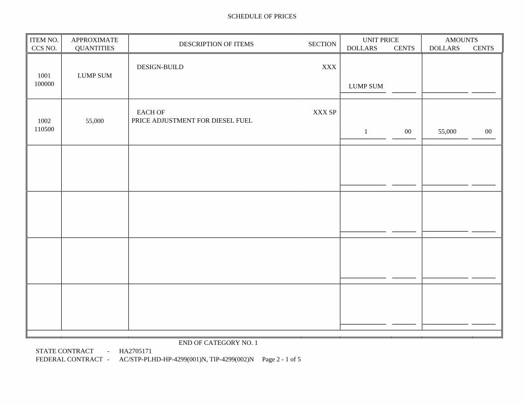
SCHEDULE OF PRICES
ITEM NO. CCS NO.
APPROXIMATE QUANTITIES DESCRIPTION OF ITEMS SECTION UNIT PRICE
DOLLARS CENTS AMOUNTS
DOLLARS CENTS
1001 100000
LUMP SUM DESIGN-BUILD XXX
LUMP SUM
1002 110500
55,000 EACH OF
PRICE ADJUSTMENT FOR DIESEL FUEL XXX SP
1 00 55,000 00
END OF CATEGORY NO. 1 STATE CONTRACT - HA2705171 FEDERAL CONTRACT - AC/STP-PLHD-HP-4299(001)N, TIP-4299(002)N Page 2 - 1 of 5

SCHEDULE OF PRICES
ITEM NO. CCS NO.
APPROXIMATE QUANTITIES DESCRIPTION OF ITEMS SECTION UNIT PRICE
DOLLARS CENTS AMOUNTS
DOLLARS CENTS
3001 300000
4 EACH OF
SEVERE WEATHER EVENT INCENTIVE XXX
28,264 00 28,264 00
3002 300000
1 EACH OF
WETLAND / WATERWAY REDUCTION INCENTIVE XXX
16,000 00 16,000 00
3003 388130
12 EACH OF
QUARTERLY EROSION AND SEDIMENT CONTROL INCENTIVE
308 SP
750 00 9,000 00
3004 388135
LUMP SUM FINAL EROSION AND SEDIMENT CONTROL
INCENTIVE 308 SP
9,000 00 9,000 00
END OF CATEGORY NO. 3 STATE CONTRACT - HA2705171 FEDERAL CONTRACT - AC/STP-PLHD-HP-4299(001)N, TIP-4299(002)N Page 2 - 2 of 5

SCHEDULE OF PRICES
ITEM NO. CCS NO.
APPROXIMATE QUANTITIES DESCRIPTION OF ITEMS SECTION UNIT PRICE
DOLLARS CENTS AMOUNTS
DOLLARS CENTS
5001 504600
110,000 EACH OF
PRICE ADJUSTMENT FOR ASPHALT BINDER 504 SP
1 00 110,000 00
END OF CATEGORY NO. 5 STATE CONTRACT - HA2705171 FEDERAL CONTRACT - AC/STP-PLHD-HP-4299(001)N, TIP-4299(002)N Page 2 - 3 of 5

SCHEDULE OF PRICES
ITEM NO. CCS NO.
APPROXIMATE QUANTITIES DESCRIPTION OF ITEMS SECTION UNIT PRICE
DOLLARS CENTS AMOUNTS
DOLLARS CENTS
8001 800000
LUMP SUM WATER (HARFORD COUNTY) XXX
LUMP SUM
8002 800000
LUMP SUM WATER AND SEWER (CITY OF ABERDEEN) XXX
LUMP SUM
END OF CATEGORY NO. 8 STATE CONTRACT - HA2705171 FEDERAL CONTRACT - AC/STP-PLHD-HP-4299(001)N, TIP-4299(002)N Page 2 - 4 of 5

SCHEDULE OF PRICES
ITEM NO. CCS NO.
APPROXIMATE QUANTITIES DESCRIPTION OF ITEMS SECTION UNIT PRICE
DOLLARS CENTS AMOUNTS
DOLLARS CENTS
AGGREGATE AMOUNT AT UNIT PRICES ALTERNATE
A IS USING BID 1001, 1002, 3001-3004, 5001, 8001, 8002
THIS PROPOSAL SHALL BE FILLED IN BY THE
BIDDER WITH PRICES IN NUMERALS AND EXTENSIONS SHALL BE MADE BY HIM.
STATE CONTRACT - HA2705171 FEDERAL CONTRACT - AC/STP-PLHD-HP-4299(001)N, TIP-4299(002)N Page 2 - 5 of 5

CONTRACT PROVISIONS CONTRACT NO. HA2705171 PROPOSAL FORM PACKET — FEDERALFAP NO. AC/STP-PLH-HP-4299(001)N & TIP-4299(002)N
07-02-09
3 of 28
GENERAL MATERIAL REQUIREMENTS
CONVICT PRODUCED MATERIALS Section 1019 of the Intermodal Surface Transportation Efficiency Act of 1991 (ISTEA) clarifies that materials produced by convict labor after July 1, 1991 may not be used for Federal-aid highway construction projects unless produced at a prison facility producing convict made materials for Federal-aid construction projects prior to July 1, 1987.
CONTRACT PROVISION BUY AMERICA The Contractor shall comply with Section 165 of the Surface Transportation Assistance Act of 1982 as amended by Section 1041(a) and 1048(a) of the Intermodal Surface Transportation Efficiency Act of 1991 with regard to the furnishing and coating of iron and steel products. A nationwide waiver for this provision has been granted for pig iron and processed, pelletized, and reduced iron ore. All bidders shall submit a bid using Domestic Iron and Steel Products with coatings that have been applied inside the United States. If the bidder elects, an additional alternate bid may be submitted using Foreign Products on one or more of the above items in this Contract. The Contract, if awarded, will be awarded to the responsible bidder who submits the lowest total bid for the Contract based on furnishing Domestic Products unless such bid exceeds the lowest total bid based on furnishing Foreign Products by more than twenty five percent (25%). Foreign Products will not be permitted to be used as a substitution for Domestic ones after the bid has been awarded. When steel and iron products and/or coatings are used in a project, the Contractor is not prohibited from using a minimal amount of foreign steel and iron products and/or coatings, if the cost of such materials used does not exceed one-tenth of one percent (0.1 %) of the total contract cost or $2,500, whichever is greater.

CONTRACT PROVISIONS CONTRACT NO. HA2705171 PROPOSAL FORM PACKET — FEDERALFAP NO. AC/STP-PLH-HP-4299(001)N & TIP-4299(002)N
07-02-09
4 of 28
ALTERNATE BID USING FOREIGN PRODUCTS
When a bidder elects to utilize Foreign Products on one or more items, the following summation indicating the Total Bid using Foreign Products must be completed in addition to the individual item bid tabulations. The following instructions are given to the bidder in completing the Total Bid summation using Foreign Products: 1 - The "Bid Total" for the initial bid using Domestic Products shall be shown on line (1). 2 - The subtotal for Item Amounts using Domestic Products shall be shown on line (2), for
those items which the Contractor elects to use Foreign Products. 3 - The subtotal for Item Amounts using Foreign Products shall be shown on line (3). 4 - The total Bid, utilizing Foreign Products shall be shown on line (4). The value is
obtained by subtracting subtotal (2) from the Total Bid (1) and then adding subtotal (3). Bid Total for Bid 1 using Line (1) Domestic items Total of Domestic Items Line (2) - Total of Foreign Items Line (3) + Bid Total using Foreign Items Line (4)

CONTRACT NO. HA2705171 PROPOSAL FORM PACKET — FEDERAL FAP NO. AC/STP-PLH-HP-4299(001)N & TIP-4299(002)N
07-02-09
5 of 28
ALTERNATE BID - USING FOREIGN PRODUCTS BIDDER'S INSTRUCTIONS
When the bidder elects to submit a bid for one or more items using Foreign Products, the following form must be used. For each item that Foreign Products are contemplated, the appropriate "Item Numbers", "Approximate Quantities", "Description of Items", "Unit Price or Lump Sum Price", "Item Amount Domestic" and "Item Amount Foreign" shall be tabulated below as specified in the initial bid. The bidder shall indicate the unit price in dollars and cents and show the total cost of the item for each item that utilizes Foreign Products. When all items utilizing Foreign Products have been listed, the bidder shall indicate on Page 4 of 20 the subtotals of the Item Amounts for Domestic Products in Line (2) and for Foreign Products in Line (3).
Item Nos.
Approximate Quantities
Description of Items Unit Price or
Lump Sum Dollars.Cts.
Items Amount Domestic
Dollars.Cts.
Items Amount Foreign
Dollars.Cts.

CONTRACT PROVISIONS CONTRACT NO. HA2705171 PROPOSAL FORM PACKET — FEDERALFAP NO. AC/STP-PLH-HP-4299(001)N & TIP-4299(002)N
07-02-09
6 of 28
BID/PROPOSAL AFFIDAVIT
A. AUTHORIZED REPRESENTATIVE AND AFFIANT I HEREBY AFFIRM THAT: I am the (title) _______________________________________ and the duly authorized representative of (business) ____________________________________ and that I possess the legal authority to make this Affidavit on behalf of myself and the business for which I am acting.
B. CERTIFICATION REGARDING COMMERCIAL NONDISCRIMINATION The undersigned bidder or offeror hereby certifies and agrees that the following information is correct: In preparing its bid on this project, the bidder or offeror has considered all proposals submitted from qualified, potential subcontractors and suppliers, and has not engaged in “discrimination” as defined in §19-103 of the State Finance and Procurement Article of the Annotated Code of Maryland. “Discrimination” means any disadvantage, difference, distinction, or preference in the solicitation, selection, hiring, or commercial treatment of a vendor, subcontractor, or commercial customer on the basis of race, color, religion, ancestry, or national origin, sex, age, marital status, sexual orientation, or on the basis of disability or any otherwise unlawful use of characteristics regarding the vendors, supplier’s or commercial customer’s employees or owners. “Discrimination” also includes retaliating against any person or other entity for reporting any incident of “discrimination”. Without limiting any other provision of the solicitation on this project, it is understood that, if the certification is false, such false certification constitutes grounds for the State to reject the bid submitted by the bidder or offeror on this project, and terminate any contract awarded based on the bid. As part of its bid or proposal, the bidder or offeror herewith submits a list of all instances within the past 4 years where there has been a final adjudicated determination in a legal or administrative proceeding in the state of Maryland that the bidder or offeror discriminated against subcontractors, vendors, suppliers, or commercial customers, and a description of the status or resolution of that determination, including any remedial action taken. Bidder or Offeror agrees to comply in all respects with the State’s Commercial Nondiscrimination Policy as described under Title 19 of the State Finance and Procurement Article of the Annotated Code of Maryland.

CONTRACT PROVISIONS CONTRACT NO. HA2705171 PROPOSAL FORM PACKET — FEDERALFAP NO. AC/STP-PLH-HP-4299(001)N & TIP-4299(002)N
07-02-09
7 of 28
C. AFFIRMATION REGARDING BRIBERY CONVICTIONS I FURTHER AFFIRM THAT: Neither I, nor to the best of my knowledge, information, and belief, the above business (as is defined in Section 16-101(b) of the State Finance and Procurement Article of the Annotated Code of Maryland), or any of its officers, directors, partners, controlling stockholders, or any of its employees directly involved in the business’s contracting activities, including obtaining or performing contracts with public bodies, has been convicted of, or has had probation before judgment imposed pursuant to Criminal Procedure Article, §6-220, Annotated Code of Maryland, or has pleaded nolo contendere to a charge of, bribery, attempted bribery, or conspiracy to bribe in violation of Maryland law, or of the law of any other state or federal law, except as follows (indicate the reasons why the affirmation cannot be given and list any conviction, plea, or imposition of probation before judgment with the date, court, official or administrative body, the sentence or disposition, the name(s) of person(s) involved, and their current positions and responsibilities with the business): ________________________________________________________________________ ________________________________________________________________________ ________________________________________________________________________.
D. AFFIRMATION REGARDING OTHER CONVICTIONS I FURTHER AFFIRM THAT: Neither I, nor to the best of my knowledge, information, and belief, the above business, or any of its officers, directors, partners, controlling stockholders, or any of its employees directly involved in the business's contracting activities including obtaining or performing contracts with public bodies, has: 1. Been convicted under state or federal statute of:
(a) a criminal offense incident to obtaining, attempting to obtain, or performing a public or private contract; or (b) fraud, embezzlement, theft, forgery, falsification or destruction of records, or receiving stolen property;
2. Been convicted of any criminal violation of a state or federal antitrust statute; 3. Been convicted under the provisions of Title 18 of the United States Code for violation of the Racketeer Influenced and Corrupt Organization Act, 18 U.S.C. §1961, et seq., or the Mail Fraud Act, 18 U.S.C. §1341, et seq., for acts in connection with the submission of bids or proposals for a public or private contract;

CONTRACT PROVISIONS CONTRACT NO. HA2705171 PROPOSAL FORM PACKET — FEDERALFAP NO. AC/STP-PLH-HP-4299(001)N & TIP-4299(002)N
07-02-09
8 of 28
4. Been convicted of a violation of the State Minority Business Enterprise Law, Section 14-308 of the State Finance and Procurement Article of the Annotated Code of Maryland; 5. Been convicted of a violation of the Section 11-205.1 of the State Finance and Procurement Article of the Annotated Code of Maryland; 6. Been convicted of conspiracy to commit any act or omission that would constitute grounds for conviction or liability under any law or statute described in subsection (1) through (5) above; 7. Been found civilly liable under a state or federal antitrust statute for acts or omissions in connection with the submission of bids or proposals for a public or private contract; 8. Been found in a final adjudicated decision to have violated the Commercial Nondiscrimination Policy under Title 19 of the State Finance and Procurement Article of the Annotated Code of Maryland with regard to a public or private contract; or 9. Admitted in writing or under oath, during the course of an official investigation or other proceedings, acts or omissions that would constitute grounds for conviction or liability under any law or statute described in Section B – C and subsections (1) through (8) above, except as follows (indicate reasons why the affirmations cannot be given, and list any conviction, plea, or imposition of probation before judgment with the date, court, official or administrative body, the sentence or disposition, the name(s) of the person(s) involved and their current positions and responsibilities with the business, and the status of any debarment): ________________________________________________________________________ ________________________________________________________________________ ________________________________________________________________________.
E. AFFIRMATION REGARDING DEBARMENT I FURTHER AFFIRM THAT: Neither I, nor to the best of my knowledge, information, and belief, the above business, or any of its officers, directors, partners, controlling stockholders, or any of its employees directly involved in the business’s contracting activities, including obtaining or performing contracts with public bodies, has ever been suspended or debarred (including being issued a limited denial of participation) by any public entity, except as follows (list each debarment or suspension providing the dates of the suspension or debarment, the name of the public entity and the status of the proceedings, the name(s) of the person(s) involved and their current positions and responsibilities with the business, the grounds of the debarment or suspension, and the details of each person's involvement in any activity that formed the grounds of the debarment or suspension): ___________________________________________________

CONTRACT PROVISIONS CONTRACT NO. HA2705171 PROPOSAL FORM PACKET — FEDERALFAP NO. AC/STP-PLH-HP-4299(001)N & TIP-4299(002)N
07-02-09
9 of 28
F. AFFIRMATION REGARDING DEBARMENT OF RELATED ENTITIES I FURTHER AFFIRM THAT:
1. The business was not established and it does not operate in a manner designed to evade the application of or defeat the purpose of debarment pursuant to Sections 16-101, et seq., of the State Finance and Procurement Article of the Annotated Code of Maryland; and 2. The business is not a successor, assignee, subsidiary, or affiliate of a suspended or debarred business, except as follows (you must indicate the reasons why the affirmations cannot be given without qualification): _______________________________________________________________________ _______________________________________________________________________ _______________________________________________________________________.
G. SUB-CONTRACT AFFIRMATION I FURTHER AFFIRM THAT: Neither I, nor to the best of my knowledge, information, and belief, the above business, has knowingly entered into a contract with a public body under which a person debarred or suspended under Title 16 of the State Finance and Procurement Article of the Annotated Code of Maryland will provide, directly or indirectly, supplies, services, architectural services, construction related services, leases of real property, or construction.
H. AFFIRMATION REGARDING COLLUSION I FURTHER AFFIRM THAT: Neither I, nor to the best of my knowledge, information, and belief, the above business has: 1. Agreed, conspired, connived, or colluded to produce a deceptive show of competition in the compilation of the accompanying bid or offer that is being submitted; 2. In any manner, directly or indirectly, entered into any agreement of any kind to fix the bid price or price proposal of the bidder or Offeror or of any competitor, or otherwise taken any action in restraint of free competitive bidding in connection with the contract for which the accompanying bid or offer is submitted.

CONTRACT PROVISIONS CONTRACT NO. HA2705171 PROPOSAL FORM PACKET — FEDERALFAP NO. AC/STP-PLH-HP-4299(001)N & TIP-4299(002)N
07-02-09
10 of 28
I. FINANCIAL DISCLOSURE AFFIRMATION I FURTHER AFFIRM THAT: I am aware of, and the above business will comply with, the provisions of Section 13-221 of the State Finance and Procurement Article of the Annotated Code of Maryland, which require that every business that enters into contracts, leases, or other agreements with the State of Maryland or its agencies during a calendar year under which the business is to receive in the aggregate $100,000 or more shall, within 30 days of the time when the aggregate value of the contracts, leases, or other agreements reaches $100,000, file with the Secretary of State of Maryland certain specified information to include disclosure of beneficial ownership of the business.
J. POLITICAL CONTRIBUTION DISCLOSURE AFFIRMATION I FURTHER AFFIRM THAT: I am aware of, and the above business will comply with, Election Law Article, §§14-101—14-108, Annotated Code of Maryland, which requires that every person that enters into contracts, leases, or other agreements with the State of Maryland, including its agencies or a political subdivision of the State, during a calendar year in which the person receives in the aggregate $100,000 or more shall file with the State Board of Elections a statement disclosing contributions in excess of $500 made during the reporting period to a candidate for elective office in any primary or general election.

CONTRACT PROVISIONS CONTRACT NO. HA2705171 PROPOSAL FORM PACKET — FEDERALFAP NO. AC/STP-PLH-HP-4299(001)N & TIP-4299(002)N
07-02-09
11 of 28
K. DRUG AND ALCOHOL FREE WORKPLACE
(Applicable to all contracts unless the contract is for a law enforcement agency and the agency head or the agency head's designee has determined that application of COMAR 21.11.08 and this certification would be inappropriate in connection with the law enforcement agency's undercover operations.) I CERTIFY THAT: 1. Terms defined in COMAR 21.11.08 shall have the same meanings when used in this certification. 2. By submission of its bid or offer, the business, if other than an individual, certifies and agrees that, with respect to its employees to be employed under a contract resulting from this solicitation, the business shall:
(a) Maintain a workplace free of drug and alcohol abuse during the term of the contract;
(b)Publish a statement notifying its employees that the unlawful manufacture, distribution, dispensing, possession, or use of drugs, and the abuse of drugs or alcohol is prohibited in the business' workplace and specifying the actions that will be taken against employees for violation of these prohibitions;
(c) Prohibit its employees from working under the influence of drugs or alcohol;
(d) Not hire or assign to work on the contract anyone whom the business knows, or in the exercise of due diligence should know, currently abuses drugs or alcohol and is not actively engaged in a bona fide drug or alcohol abuse assistance or rehabilitation program;
(e) Promptly inform the appropriate law enforcement agency of every drug-related crime that occurs in its workplace if the business has observed the violation or otherwise has reliable information that a violation has occurred;
(f) Establish drug and alcohol abuse awareness programs to inform its employees about:
(i) The dangers of drug and alcohol abuse in the workplace; (ii) The business' policy of maintaining a drug and alcohol free workplace; (iii) Any available drug and alcohol counseling, rehabilitation, and employee assistance programs; and (iv) The penalties that may be imposed upon employees who abuse drugs and alcohol in the workplace;
12 of 28

CONTRACT PROVISIONS CONTRACT NO. HA2705171 PROPOSAL FORM PACKET — FEDERALFAP NO. AC/STP-PLH-HP-4299(001)N & TIP-4299(002)N
07-02-09
(g) Provide all employees engaged in the performance of the contract with a copy of the statement required by §K(2)(b), above;
(h) Notify its employees in the statement required by §K(2)(b), above, that as a condition of continued employment on the contract, the employee shall:
(i) Abide by the terms of the statement; and (ii) Notify the employer of any criminal drug or alcohol abuse conviction for an offense occurring in the workplace not later than 5 days after a conviction;
(i) Notify the procurement officer within 10 days after receiving notice under §K(2)(h)(ii), above, or otherwise receiving actual notice of a conviction;
(j) Within 30 days after receiving notice under §K(2)(h)(ii), above, or otherwise receiving actual notice of a conviction, impose either of the following sanctions or remedial measures on any employee who is convicted of a drug or alcohol abuse offense occurring in the workplace:
(i) Take appropriate personnel action against an employee, up to and including termination; or (ii) Require an employee to satisfactorily participate in a bona fide drug or alcohol abuse assistance or rehabilitation program; and
(k) Make a good faith effort to maintain a drug and alcohol free workplace through implementation of §K(2)(a)—(j), above.
3. If the business is an individual, the individual shall certify and agree as set forth in §K(4), below, that the individual shall not engage in the unlawful manufacture, distribution, dispensing, possession, or use of drugs or the abuse of drugs or alcohol in the performance of the contract. 4. I acknowledge and agree that:
(a) The award of the contract is conditional upon compliance with COMAR 21.11.08 and this certification; (b) The violation of the provisions of COMAR 21.11.08 or this certification shall be cause to suspend payments under, or terminate the contract for default under COMAR 21.07.01.11 or 21.07.03.15, as applicable; and (c) The violation of the provisions of COMAR 21.11.08 or this certification in connection with the contract may, in the exercise of the discretion of the Board of Public Works, result in suspension and debarment of the business under COMAR 21.08.03.
13 of 28

CONTRACT PROVISIONS CONTRACT NO. HA2705171 PROPOSAL FORM PACKET — FEDERALFAP NO. AC/STP-PLH-HP-4299(001)N & TIP-4299(002)N
07-02-09
L. CERTIFICATION OF CORPORATION REGISTRATION AND TAX PAYMENT
I FURTHER AFFIRM THAT:
1 The business named above is a (domestic ___ ) (foreign __ ) corporation registered in accordance with the Corporations and Associations Article, Annotated Code of Maryland, and that it is in good standing and has filed all of its annual reports, together with filing fees, with the Maryland State Department of Assessments and Taxation, and that the name and address of its resident agent filed with the State Department of Assessments and Taxation is (IF NOT APPLICABLE, SO STATE):
Name: __________________________ Address: __________________________
__________________________ __________________________
2. Except as validly contested, the business has paid, or has arranged for payment of,
all taxes due the State of Maryland and has filed all required returns and reports with the Comptroller of the Treasury, the State Department of Assessments and Taxation, and the Department of Labor, Licensing, and Regulation, as applicable, and will have paid all withholding taxes due the State of Maryland prior to final settlement.
M. CONTINGENT FEES
I FURTHER AFFIRM THAT:
The business has not employed or retained any person, partnership, corporation, or other entity, other than a bona fide employee, bona fide agent, bona fide salesperson, or commercial selling agency working for the business, to solicit or secure the Contract, and that the business has not paid or agreed to pay any person, partnership, corporation, or other entity, other than a bona fide employee, bona fide agent, bona fide salesperson, or commercial selling agency, any fee or any other consideration contingent on the making of the Contract.
N. REPEALED

CONTRACT PROVISIONS CONTRACT NO. HA2705171 PROPOSAL FORM PACKET — FEDERALFAP NO. AC/STP-PLH-HP-4299(001)N & TIP-4299(002)N
07-02-09
14 of 28
O. ACKNOWLEDGEMENT
I ACKNOWLEDGE THAT this Affidavit is to be furnished to the Procurement Officer and may be distributed to units of: (1) the State of Maryland; (2) counties or other subdivisions of the State of Maryland; (3) other states; and (4) the federal government. I further acknowledge that this Affidavit is subject to applicable laws of the United States and the State of Maryland, both criminal and civil, and that nothing in this Affidavit or any contract resulting from the submission of this bid or proposal shall be construed to supersede, amend, modify or waive, on behalf of the State of Maryland, or any unit of the State of Maryland having jurisdiction, the exercise of any statutory right or remedy conferred by the Constitution and the laws of Maryland with respect to any misrepresentation made or any violation of the obligations, terms and convenants undertaken by the above business with respect to (1) this Affidavit, (2) the contract, and (3) other Affidavits comprising part of the contract. I DO SOLEMNLY DECLARE AND AFFIRM UNDER THE PENALTIES OF PERJURY THAT THE CONTENTS OF THIS AFFIDAVIT ARE TRUE AND CORRECT TO THE BEST OF MY KNOWLEDGE, INFORMATION, AND BELIEF. Date: ____________ By: ______________________________
(Authorized Representative and Affiant)

CONTRACT PROVISIONS CONTRACT NO. HA2705171 PROPOSAL FORM PACKET — FEDERALFAP NO. AC/STP-PLH-HP-4299(001)N & TIP-4299(002)N
07-02-09
15 of 28
COMPREHENSIVE SIGNATURE PAGE 1 OF 2 THE BIDDER IS HEREBY NOTIFIED THAT THIS DOCUMENT SHALL BE SIGNED IN INK IN ORDER FOR THE BID TO BE ACCEPTED. BY SIGNING, THE BIDDER CERTIFIES THAT HE/SHE WILL COMPLY IN EVERY ASPECT WITH THESE SPECIFICATIONS. FURTHER, I DO SOLEMNLY DECLARE AND AFFIRM UNDER THE PENALTIES OF PERJURY THAT THE CONTENTS OF THIS AFFIDAVIT (PARAGRAPHS A-N) ARE TRUE AND CORRECT TO THE BEST OF MY KNOWLEDGE, INFORMATION, AND BELIEF. This bid form shall be filled out legibly in ink or typed. The bid, if submitted by an individual, shall be signed by an individual; if submitted by a partnership, shall be signed by such member or members of the partnership as have authority to bind the partnership; if submitted by a corporation the same shall be signed by the President and attested by the Secretary or an Assistant Secretary. If not signed by the President as aforesaid, there must be attached a copy of that portion of the By-Laws, or a copy of a Board resolution, duly certified by the Secretary, showing the authority of the person so signing on behalf of the corporation. In lieu thereof, the corporation may file such evidence with the Administration, duly certified by the Secretary, together with a list of the names of those officers having authority to execute documents on behalf of the corporation, duly certified by the Secretary, which listing shall remain in full force and effect until such time as the Administration is advised in writing to the contrary. In any case where a bid is signed by an Attorney in Fact the same must be accompanied by a copy of the appointing document, duly certified. IF AN INDIVIDUAL: NAME: Street and/or P.O. Box City State Zip Code Fed ID or SSN (SEAL) Signature Date Print Signature WITNESS: Signature Print Signature

CONTRACT PROVISIONS CONTRACT NO. HA2705171 PROPOSAL FORM PACKET — FEDERALFAP NO. AC/STP-PLH-HP-4299(001)N & TIP-4299(002)N
07-02-09
16 of 28
COMPREHENSIVE SIGNATURE PAGE 2 OF 2 IF A PARTNERSHIP: NAME OF PARTNERSHIP: Street and/or P.O. Box City State Zip Code Fed ID or SSN BY: (SEAL) Member Signature Date Print Signature TITLE: WITNESS: Signature Print Signature IF A CORPORATION: NAME OF CORPORATION: Street and/or P.O. Box City State Zip Code Fed ID or SSN STATE OF INCORPORATION: BY: (SEAL) Signature Date Print Signature TITLE: WITNESS: Secretary’s Signature Print Signature

CONTRACT PROVISIONS CONTRACT NO. HA2705171 PROPOSAL FORM PACKET — FEDERALFAP NO. AC/STP-PLH-HP-4299(001)N & TIP-4299(002)N
07-02-09
17 of 28
MDOT DBE FORM A - (MDOT-OP 016-2) FEDERALLY-FUNDED CONTRACTS (BIDS ONLY)
CERTIFIED DBE UTILIZATION AND FAIR SOLICITATION AFFIDAVIT Page 1 of 2
THIS AFFIDAVIT MUST BE INCLUDED WITH THE BID. IF THE BIDDER FAILS TO ACCURATELY COMPLETE AND SUBMIT THIS AFFIDAVIT AS REQUIRED, THE BID SHALL BE DEEMED NOT RESPONSIVE. In connection with the proposal submitted in response to Solicitation No. HA2705171, I affirm the following:
1. DBE Participation (PLEASE CHECK ONLY ONE)
I have met the overall certified Disadvantaged Business Enterprise (DBE) participation goal of Thirty percent (30%%). I agree that the DBE firms listed in the DBE Participation Schedule - Part 2 of the MDOT DBE Form B (Federally-Funded Contracts – Bids Only) will be used to accomplish the DBE participation goal for this Contract for at least the dollar amounts set forth therein.
OR
I conclude that I am unable to achieve the DBE participation goal. I hereby request a waiver of
the overall goal. Within 10 business days of receiving notice that our firm is the apparent awardee or as requested by the Procurement Officer, I will submit a written waiver request and all required documentation in accordance with COMAR 21.11.03.11. I agree that the DBE firms listed in the DBE Participation Schedule - Part 2 of the MDOT DBE Form B (Federally-Funded Contracts – Bids Only) will be used to accomplish the DBE participation goal for this Contract for at least the dollar amounts set forth therein.
2. Additional DBE Documentation
I understand that if I am notified that I am the apparent awardee or as requested by the Procurement Officer, I must submit the following documentation within 10 business days of receiving such notice: (a) Outreach Efforts Compliance Statement (MDOT DBE Form C - Federally-Funded Contracts – Bids Only); (b) Subcontractor Project Participation Statement (MDOT DBE Form D - Federally-Funded Contracts – Bids Only); (c) DBE Waiver Request documentation per COMAR 21.11.03.11 (if waiver was requested); and (d) Any other documentation required by the Procurement Officer to ascertain bidder’s responsibility in connection with the certified DBE participation goal.
I acknowledge that if I fail to return each completed document (in 2 (a) through (d)) within the required time, the Procurement Officer may determine that I am not responsible and therefore not eligible for contract award.

CONTRACT PROVISIONS CONTRACT NO. HA2705171 PROPOSAL FORM PACKET — FEDERALFAP NO. AC/STP-PLH-HP-4299(001)N & TIP-4299(002)N
07-02-09
18 of 28
MDOT DBE FORM A - (MDOT-OP 016-2) FEDERALLY-FUNDED CONTRACTS (BIDS ONLY)
CERTIFIED DBE UTILIZATION AND FAIR SOLICITATION AFFIDAVIT Page 2 of 2
3. Information Provided to DBE firms
In the solicitation of subcontract quotations or offers, DBE firms were provided not less than the same information and amount of time to respond as were non-DBE firms.
I solemnly affirm under the penalties of perjury that the information in this affidavit is true to the best of my knowledge, information and belief.
_________________________ ________________________ Company Name Signature of Representative
_________________________ ________________________ Address Printed Name and Title
_________________________ ________________________ City, State and Zip Code Date
SUBMIT THIS AFFIDAVIT WITH BID/PROPOSAL
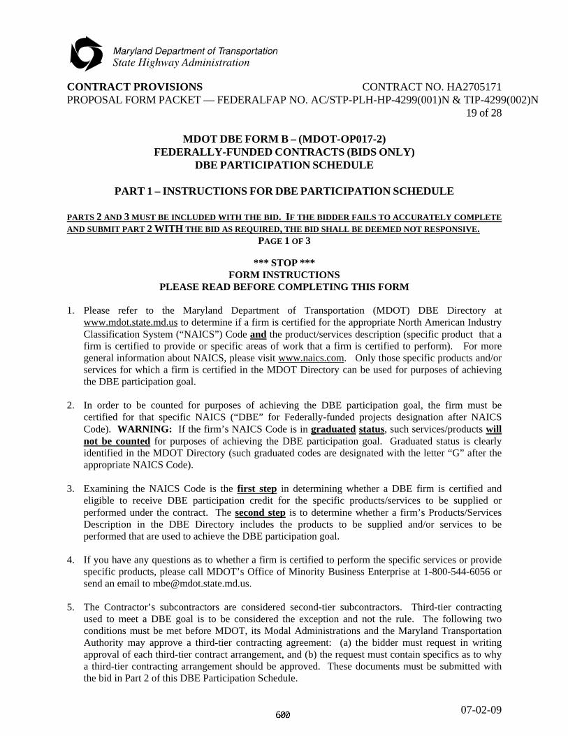
CONTRACT PROVISIONS CONTRACT NO. HA2705171 PROPOSAL FORM PACKET — FEDERALFAP NO. AC/STP-PLH-HP-4299(001)N & TIP-4299(002)N
07-02-09
19 of 28
MDOT DBE FORM B – (MDOT-OP017-2) FEDERALLY-FUNDED CONTRACTS (BIDS ONLY)
DBE PARTICIPATION SCHEDULE
PART 1 – INSTRUCTIONS FOR DBE PARTICIPATION SCHEDULE
PARTS 2 AND 3 MUST BE INCLUDED WITH THE BID. IF THE BIDDER FAILS TO ACCURATELY COMPLETE AND SUBMIT PART 2 WITH THE BID AS REQUIRED, THE BID SHALL BE DEEMED NOT RESPONSIVE.
PAGE 1 OF 3
*** STOP *** FORM INSTRUCTIONS
PLEASE READ BEFORE COMPLETING THIS FORM 1. Please refer to the Maryland Department of Transportation (MDOT) DBE Directory at
www.mdot.state.md.us to determine if a firm is certified for the appropriate North American Industry Classification System (“NAICS”) Code and the product/services description (specific product that a firm is certified to provide or specific areas of work that a firm is certified to perform). For more general information about NAICS, please visit www.naics.com. Only those specific products and/or services for which a firm is certified in the MDOT Directory can be used for purposes of achieving the DBE participation goal.
2. In order to be counted for purposes of achieving the DBE participation goal, the firm must be
certified for that specific NAICS (“DBE” for Federally-funded projects designation after NAICS Code). WARNING: If the firm’s NAICS Code is in graduated status, such services/products will not be counted for purposes of achieving the DBE participation goal. Graduated status is clearly identified in the MDOT Directory (such graduated codes are designated with the letter “G” after the appropriate NAICS Code).
3. Examining the NAICS Code is the first step in determining whether a DBE firm is certified and
eligible to receive DBE participation credit for the specific products/services to be supplied or performed under the contract. The second step is to determine whether a firm’s Products/Services Description in the DBE Directory includes the products to be supplied and/or services to be performed that are used to achieve the DBE participation goal.
4. If you have any questions as to whether a firm is certified to perform the specific services or provide
specific products, please call MDOT’s Office of Minority Business Enterprise at 1-800-544-6056 or send an email to [email protected].
5. The Contractor’s subcontractors are considered second-tier subcontractors. Third-tier contracting
used to meet a DBE goal is to be considered the exception and not the rule. The following two conditions must be met before MDOT, its Modal Administrations and the Maryland Transportation Authority may approve a third-tier contracting agreement: (a) the bidder must request in writing approval of each third-tier contract arrangement, and (b) the request must contain specifics as to why a third-tier contracting arrangement should be approved. These documents must be submitted with the bid in Part 2 of this DBE Participation Schedule.

CONTRACT PROVISIONS CONTRACT NO. HA2705171 PROPOSAL FORM PACKET — FEDERALFAP NO. AC/STP-PLH-HP-4299(001)N & TIP-4299(002)N
07-02-09
20 of 28
MDOT DBE FORM B – (MDOT-OP017-2) FEDERALLY-FUNDED CONTRACTS (BIDS ONLY)
DBE PARTICIPATION SCHEDULE
PART 1 – INSTRUCTIONS FOR DBE PARTICIPATION SCHEDULE PAGE 2 OF 3
6. For each DBE firm that is being used as supplier/wholesaler/regular dealer/broker/manufacturer,
please follow these instructions for calculating the dollar amount of the subcontract for purposes of achieving the DBE participation goal:
A. Is the firm certified as a broker of the products/supplies? If the answer is YES, please continue to
Item C. If the answer is NO, please continue to Item B. B. Is the firm certified as a supplier, wholesaler, regular dealer, or manufacturer of such
products/supplies? If the answer is YES, continue to Item D. If the answer is NO, continue to Item C only if the DBE firm is certified to perform trucking/hauling services under NAICS Codes 484110, 484121, 484122, 484210, 484220 and 484230. If the answer is NO and the firm is not certified under these NAICS Codes, then no DBE participation credit will be given for the supply of these products.
C. For purposes of achieving the DBE participation goal, you may count only the amount of any
reasonable fee that the DBE firm will receive for the provision of such products/supplies - not the total subcontract amount or the value (or a percentage thereof) of such products and/or supplies. In Column 4 of the DBE Participation Schedule, please state the amount of any reasonable fee that the DBE firm will receive for the provision of such products/services in Line 4.1.
D. Is the firm certified as a manufacturer (refer to the firm’s NAICS Code and specific description of
products/services) of the products/supplies to be provided? If the answer is NO, please continue to Item E. If the answer is YES, for purposes of achieving the DBE participation goal, you may count the total amount of the subcontract. In Column 4 of the DBE Participation Schedule, please state the total amount of the subcontract in Line 4.1.
E. Is the firm certified as a supplier, wholesaler and/or regular dealer? If the answer is YES (i) if the
DBE firm is furnishing and installing the materials and is certified to perform these services, please include in Line 4.1 the total value of the subcontract amount (including full value of supplies); or (ii) if the firm is only being used as a supplier, wholesaler and/or regular dealer or is not certified to install the supplies/materials, for purposes of achieving the DBE participation goal, you may only count sixty percent (60%) of the value of the subcontract for these supplies/products (60% Rule). In Line 4.2 of the DBE Participation Schedule, please state amount of the subcontract for these supplies/products only (not installation) and sixty percent (60%) of such value.

CONTRACT PROVISIONS CONTRACT NO. HA2705171 PROPOSAL FORM PACKET — FEDERALFAP NO. AC/STP-PLH-HP-4299(001)N & TIP-4299(002)N
07-02-09
21 of 28
MDOT DBE FORM B – (MDOT-OP017-2) FEDERALLY-FUNDED CONTRACTS (BIDS ONLY)
DBE PARTICIPATION SCHEDULE
PART 1 – INSTRUCTIONS FOR DBE PARTICIPATION SCHEDULE PAGE 3 OF 3
7. Please note that for USDOT-funded projects, a DBE prime may count towards its DBE participation
goal, work performed by its own forces. Include information about the DBE prime in Part 2.
8. WARNING: The percentage of DBE participation, computed using the dollar amounts in Column 4 for all of the DBE firms listed in Part 2, MUST equal at least the DBE participation goal as set forth in MDOT DBE Form A – Federally-Funded Contracts (Bids Only) for this solicitation. If a bidder is unable to achieve the DBE participation goal, then the bidder must request a waiver in Form A or the bid shall be deemed not responsive. You may wish to use the Worksheet shown below to assist you in calculating the percentages and confirming that you have met the applicable DBE participation goal.
WORKSHEET
Total DBE Firm Participation Amount $_______________________________________________
(Add amounts listed for all DBE Firms
in Column 4 of DBE Participation Schedule)
Divide by Total Contract Amount ÷________________________________________________
Percent Overall DBE Participation =_____________________________________

CONTRACT PROVISIONS CONTRACT NO. HA2705171 PROPOSAL FORM PACKET — FEDERALFAP NO. AC/STP-PLH-HP-4299(001)N & TIP-4299(002)N
07-02-09
22 of 28
MDOT DBE FORM B – (MDOT-OP017-2) FEDERALLY-FUNDED CONTRACTS (BIDS ONLY)
DBE PARTICIPATION SCHEDULE
PART 2 – DBE PARTICIPATION SCHEDULE
PART 2 MUST BE INCLUDED WITH THE BID. IF THE BIDDER FAILS TO ACCURATELY COMPLETE AND SUBMIT PART 2 WITH THE BID AS REQUIRED, THE BID SHALL BE DEEMED NOT RESPONSIVE.
PAGE __ OF ___
LIST INFORMATION FOR EACH CERTIFIED MBE SUBCONTRACTOR USED TO ACHIEVE THE DBE PARTICIPATION GOAL. COLUMN 1 COLUMN 2 COLUMN 3 COLUMN 4
Unless the bidder requested a waiver in MDOT DBE Form A – Federally Funded Contracts (Bids Only) for this solicitation, the cumulative DBE participation for all DBE firms listed herein must equal at least the DBE participation goal set forth in Form A.
NAME OF DBE PRIME OR SUBCONTRACTOR AND TIER
CERTIFICATION NO. AND CLASSIFICATION
NAICS CODE/S NAICS Code/s of the specific products to be supplied or services to be performed by the DBE firm
FOR PURPOSES OF ACHIEVING THE DBE PARTICIPATION GOAL. State the dollar amount of the products/services in Line 4.1 except for those services or products where the DBE firm is being used as a wholesaler, supplier or regular dealer. For those items of work where the DBE firm is being used as a supplier, wholesaler and/or regular dealer complete Line 4.2 using the 60% Rule.
Please check if DBE firm is a third-tier contractor (if applicable). Please submit written documents in accordance with Section 5 of Part 1 - Instructions
Certification Number:
Women-Owned African American-
Owned Other DBE
Classification
4.1 TOTAL AMOUNT TO BE PAID TO THE SUBCONTRACTOR (EXCLUDING PRODUCTS/SERVICES FROM SUPPLIERS, WHOLESALERS, AND REGULAR DEALERS). $ 4.2 TOTAL AMOUNT TO BE PAID TO THE SUBCONTRACTOR FOR ITEMS OF WORK WHERE THE DBE FIRM IS BEING USED AS A SUPPLIER, WHOLESALER AND/OR REGULAR DEALER. (PLEASE REFER TO SECTION 6(E) IN PART 1 - INSTRUCTIONS). Total value of Supplies/Products $ X 60% (60% Rule) = $
(Amount for purposes of achieving the DBE Participation Goal).
Please check if Continuation Sheets are attached.
Prime Contractor Project Description Solicitation Number

CONTRACT PROVISIONS CONTRACT NO. HA2705171 PROPOSAL FORM PACKET — FEDERALFAP NO. AC/STP-PLH-HP-4299(001)N & TIP-4299(002)N
07-02-09
23 of 28
MDOT DBE FORM B – (MDOT-OP017-2) FEDERALLY-FUNDED CONTRACTS (BIDS ONLY)
DBE PARTICIPATION SCHEDULE
CONTINUATION SHEET
PAGE __ OF ___
LIST INFORMATION FOR EACH CERTIFIED MBE SUBCONTRACTOR USED TO ACHIEVE THE DBE PARTICIPATION GOAL. COLUMN 1 COLUMN 2 COLUMN 3 COLUMN 4
Unless the bidder requested a waiver in MDOT DBE Form A – Federally Funded Contracts (Bids Only) for this solicitation, the cumulative DBE participation for all DBE firms listed herein must equal at least the DBE participation goal set forth in Form A.
NAME OF DBE PRIME OR SUBCONTRACTOR AND TIER
CERTIFICATION NO. AND CLASSIFICATION
NAICS CODE/S NAICS Code/s of the specific products to be supplied or services to be performed by the DBE firm
FOR PURPOSES OF ACHIEVING THE DBE PARTICIPATION GOAL. State the dollar amount of the products/services in Line 4.1 except for those services or products where the DBE firm is being used as a wholesaler, supplier or regular dealer. For those items of work where the DBE firm is being used as a supplier, wholesaler and/or regular dealer complete Line 4.2 using the 60% Rule.
Please check if DBE firm is a third-tier contractor (if applicable). Please submit written documents in accordance with Section 5 of Part 1 - Instructions
Certification Number:
Women-Owned African American-
Owned Other DBE
Classification
4.1 TOTAL AMOUNT TO BE PAID TO THE SUBCONTRACTOR (EXCLUDING PRODUCTS/SERVICES FROM SUPPLIERS, WHOLESALERS OR REGULAR DEALERS). $ 4.2 TOTAL AMOUNT TO BE PAID TO THE SUBCONTRACTOR FOR ITEMS OF WORK WHERE THE DBE FIRM IS BEING USED AS A SUPPLIER, WHOLESALER AND/OR REGULAR DEALER. (PLEASE REFER TO SECTION 6(E) IN PART 1 - INSTRUCTIONS). Total value of Supplies/Products $ X 60% (60% Rule) = $
(Amount for purposes of achieving the DBE Participation Goal).
Please check if Continuation Sheets are attached.
Prime Contractor Project Description Solicitation Number

CONTRACT PROVISIONS CONTRACT NO. HA2705171 PROPOSAL FORM PACKET — FEDERALFAP NO. AC/STP-PLH-HP-4299(001)N & TIP-4299(002)N
07-02-09
24 of 28
MDOT DBE FORM B – (MDOT-OP017-2) FEDERALLY-FUNDED CONTRACTS (BIDS ONLY)
DBE PARTICIPATION SCHEDULE
PART 3 – CERTIFICATION FOR DBE PARTICIPATION SCHEDULE
PARTS 2 AND 3 MUST BE INCLUDED WITH THE BID, AS DIRECTED IN THE SOLICITATION.
I hereby affirm that I have reviewed the Products and Services Description (specific product that a firm is certified to provide or areas of work that a firm is certified to perform) set forth in the MDOT DBE Directory for each of the DBE firms listed in Part 2 of this DBE Form B for purposes of achieving the DBE participation goal that was identified in the DBE Form A that I submitted with this solicitation, and that the DBE firms listed are only performing those products/services/areas of work for which they are certified. I also hereby affirm that I have read and understand the form instructions set forth in Part 1 of this DBE Form B. I solemnly affirm under the penalties of perjury that the contents of Parts 2 and 3 of MDOT DBE Form B are true to the best of my knowledge, information and belief. ____________________________________ ______________________________ Company Name Signature of Representative ____________________________________ ______________________________ Address Printed Name and Title ____________________________________ ______________________________ City, State and Zip Code Date

CONTRACT PROVISIONS CONTRACT NO. HA2705171 PROPOSAL FORM PACKET — FEDERALFAP NO. AC/STP-PLH-HP-4299(001)N & TIP-4299(002)N
07-02-09
25 of 28
INFORMATION REQUIRED TO BE SUBMITTED FOR FEDERALLY ASSISTED CONTRACTS:
(a) Each bidder shall provide the following information:
NAME OF FIRM: Street and/or P.O. Box City State Zip Code DBE Non-DBE Age of the firm years
Annual gross receipts per last calendar year <$500,000 $500,000-1,000,000 $1,000,000-3,000,000 $3,000,000-5,000,000 $5,000,000-10,000,000 >$10,000,000
(b) Each bidder shall provide the following information for each firm quoting or
considered as subcontractors and/or suppliers: NAME OF FIRM:
Street and/or P.O. Box City State Zip Code DBE Non-DBE Age of the firm years
Annual gross receipts per last calendar year <$500,000 $500,000-1,000,000 $1,000,000-3,000,000 $3,000,000-5,000,000 $5,000,000-10,000,000 > $10,000,000
NAME OF FIRM:
Street and/or P.O. Box City State Zip Code DBE Non-DBE Age of the firm years
Annual gross receipts per last calendar year <$500,000 $500,000-1,000,000 $1,000,000-3,000,000 $3,000,000-5,000,000 $5,000,000-10,000,000
> $10,000,000

CONTRACT PROVISIONS CONTRACT NO. HA2705171 PROPOSAL FORM PACKET — FEDERALFAP NO. AC/STP-PLH-HP-4299(001)N & TIP-4299(002)N
07-02-09
26 of 28
NAME OF FIRM: Street and/or P.O. Box City State Zip Code DBE Non-DBE Age of the firm years
Annual gross receipts per last calendar year <$500,000 $500,000-1,000,000 $1,000,000-3,000,000 $3,000,000-5,000,000 $5,000,000-10,000,000 > $10,000,000
NAME OF FIRM: Street and/or P.O. Box City State Zip Code DBE Non-DBE Age of the firm years
Annual gross receipts per last calendar year <$500,000 $500,000-1,000,000 $1,000,000-3,000,000 $3,000,000-5,000,000 $5,000,000-10,000,000 > $10,000,000
NAME OF FIRM: Street and/or P.O. Box City State Zip Code DBE Non-DBE Age of the firm years
Annual gross receipts per last calendar year <$500,000 $500,000-1,000,000 $1,000,000-3,000,000 $3,000,000-5,000,000 $5,000,000-10,000,000 > $10,000,000
Submit additional copies of this page as page 26A of 28, 26B of 28, etc. as necessary, and place them as the last pages in the Invitation for Bids. Place an “X” for “NO” on the last copy. Any additional Copies: NO YES

CONTRACT PROVISIONS CONTRACT NO. HA2705171 PROPOSAL FORM PACKET — FEDERALFAP NO. AC/STP-PLH-HP-4299(001)N & TIP-4299(002)N
07-02-09
27 of 28
EXTRA WORK, CONTRACT TIME, BONDING, LIQUIDATED DAMAGES, AND PROPOSAL GUARANTY EXTRA WORK. It is further proposed to do all "Extra Work" which may be required to complete the work contemplated at unit prices or lump sum prices to be agreed upon in writing prior to starting such extra work, or if such prices or sums cannot be agreed upon, to perform such work on a Force Account basis as specified in TC-7.03. CONTRACT TIME. To commence work as specified in the "Notice to Proceed" and to prosecute the work to complete the contract within/or before N/A (working days) Wednesday, July 31, 2013(calendar date) Any delay in awarding or the execution of this contract will not be considered as a basis for any monetary claim, however, an extension of time may be considered by the Administration, if warranted. BONDING. When the Contractor's bid is $100,000 or more, the Contractor shall furnish a Payment Bond and a Performance Bond in the full amount of the Contract Award as security for the construction and completion of the contract in conformance with the Plans, Standard Specifications, revisions thereto, General Provisions and Special Provisions. To guarantee all of the work performed under this contract to be done in conformance with the Standard Specifications, revisions thereto, General Provisions and Special Provisions in a good workmanlike manner and to renew or repair any work which may be rejected due to defective materials or workmanship, prior to final completion and acceptance of the work, also we have the equipment, labor, supervision and financial capacity to perform this contract either with our organization or with Subcontractors.

CONTRACT PROVISIONS CONTRACT NO. HA2705171 PROPOSAL FORM PACKET — FEDERALFAP NO. AC/STP-PLH-HP-4299(001)N & TIP-4299(002)N
07-02-09
28 of 28
LIQUIDATED DAMAGES. The Contractor is hereby advised that liquidated damages in the amount of N/A dollars (N/A) per working day two thousand eight hundred ten dollars dollars ($2810) per calendar day will be assessed for unauthorized extensions beyond the contracted time of completion. PROPOSAL GUARANTY. A bid security is not required on Contract Proposals under $100,000. A bid security totaling at least five percent (5%) of the bid amount will be required on contracts of $100,000 or over. Acceptable forms of security for bid guaranty shall be: (1) A bond in a form satisfactory to the State underwritten by a company licensed to issue
bonds in this State; (2) A bank certified check, bank cashier's check, bank treasurer's check, or cash; (3) Pledge of security backed by the full faith and full credit of the United States government
or bonds issued by the State of Maryland. Enclosed herewith, find bid security based on at least five percent (5%) of the aggregate amount of the bid submitted, and made payable to the "State of Maryland". This bid security is a Proposal Guarantee (which is understood will be forfeited in the event the contract is not executed, if awarded to the signer of this affidavit).