martian greenhouse design for the nasa...
TRANSCRIPT
31st Space Symposium, Technical Track, Colorado Springs, Colorado, United States of America Presented on April 13-14, 2015
Copyright © 2015 by the authors. All rights reserved. Page 1 of 16
MARTIAN GREENHOUSE DESIGN FOR THE NASA EXPLORATION HABITAT PROGRAM
Geoff Kibble* and Jamey Jacob†
Oklahoma State University, [email protected]
ABSTRACT
Long duration, manned space missions to Mars create many technical challenges and logistics of sustainability
present some of the most significant questions. Mars’ pattern of orbit brings it closest to Earth once every two
years, and this is the optimal time to send payload on the two to three hundred day journey. Because of the
lengthy gap between optimal launching times, designs for terrestrial missions to Mars must provide storage
capable of holding two years’ worth of supplies or include the ability for self-sustainment. Regular frequent
shipping is implausible for replenishing supplies on Mars; even the amount of fuel required to send this large
payload during the optimal time poses a problem. This cost alone raises questions about the feasibility of such
missions. In order to successfully place a station on the Martian surface, the mission design must include a means
for producing food, thereby creating some degree of self-sustainability. Fresh grown foods are essential for long-
term sustainability, without which manned missions to Mars will continue to be limited in scope. Oklahoma State
University is investigating various methods for producing food on the Martian surface as part of the 2015
eXploration Habitat (X-Hab) Academic Innovation Challenge sponsored by NASA and the National Space Grant
Foundation. Previous OSU X-Hab missions developed Earth analogs for Martian transit and surface habitation, and
the greenhouse complements the mission analogs. Our team is analyzing possible designs in search of the most
feasible and useful concepts and will produce a full-scale model to prove their viability. The present design
incorporates a solid central structure that is integrated with inflatable growing modules to maximize the plant
growth footprint while reducing total mass and packed volume. In the current approach, deployment and
structural design are driven by plant growth requirements and minimal crew interaction.
INTRODUCTION
NASA continues to study Mars and has successfully carried out multiple satellite, lander, and rover missions to
the orange planet, which have resulted in numerous findings pertaining to Martian atmosphere density and
composition data1, evidence to suggest the presence of ancient aqueous environments on the surface2, and the
presence of organic compounds3. However, each new discovery made on Mars, usually brings forth more
questions and uncertainty, as with the recently discovered increased levels of methane, which suggests that
methane is currently being produced from a still unknown source4. In order to solve mysteries such as these, new
technologies are needed on the planet’s surface, which requires space exploration entities to devote decades of
time and billions5 of dollars toward developing specialized payloads.
Time is one of the major factors hindering space exploration. Space rated systems required to successfully
complete these missions must go through specialized development, often using technologies at low readiness
levels. Small-quantity manufacturing of unique parts and scientific cargo takes much longer than traditional mass
production. All mission hardware undergoes rigorous certification testing to insure high probability of mission
success. Then, the system must be transported to Mars, and economical interplanetary travel always costs in time
what it saves in money. In fact, in many cases “…missions take years to develop and by the time they launch, their
technology is already outdated”.6
* Undergraduate student. [email protected]. † Ray and Linda Booker Professor of Aerospace Engineering, [email protected].

31st Space Symposium, Technical Track, Colorado Springs, Colorado, United States of America Presented on April 13-14, 2015
Page 2 of 16
Funding is the other, more obvious, factor impeding space exploration. NASA’s budget has been consistently
reduced since the Apollo missions, due the end of the space race and the lack of obvious and immediate benefits
from the expenditures. However, space exploration and research from the Apollo missions alone have contributed
to numerous modern technologies. Some advancements in the medical field alone are the now standard, such as
the self-defibrillating pace maker which wirelessly communicates with physicians, the programmable and
implantable medication system currently used in every modern medical facility to deliver medication to patients,
and medical imaging systems which allow doctors to detect tumors, organ failures, bone fractures, or any
otherwise undetectable internal medical irregularity.7 These are only a few examples of technological influences
from the earliest space programs and are representative of only one industry. Consideration of all of the benefits
of the United States’ space program validates the idea that “we are living off the investments made a generation
ago”.8 However, no matter how beneficial the space program has proven to be, or how important it could be to
our future, the industry must adapt to mandated funding cuts and press forward under these new circumstances.
A solution to the funding and time constraints associated with seeking answers to questions surrounding
Mars, is to place scientists on its surface. This would expedite the research process and allow scientists to adapt
with the results of their studies, something that robots cannot do. The large initial investment of time and money
required to land humans on Mars would produce greater scientific results, while in the long term saving time, and
ultimately money, that is currently used to design small-scale exploratory robotic missions. However, putting
humans on Mars presents its own set of obstacles. The feasibility of a mission to Mars has been in question for
many years. Research suggests that a manned “Free-Return” mission to Mars could be accomplished as soon as
January 2018.9 However, a manned mission to the surface is further away. The ambitious Martian colonization
effort, Mars One, plans to launch their first crew members to the surface of Mars in 2024.10 NASA’s more
traditional approach, of multiple small-scale missions leading up to a manned mission to the surface, is tentatively
set for the 2030’s. Regardless of when each space exploration entity plans to land humans on Mars, their missions
have one thing in common; all require more research and technological advances in order to become a reality.
Food for astronauts on Mars is one of the most significant factors affecting long duration Martian mission
feasibility. The cost associated with transporting all the food necessary to maintain a prolonged outpost on Mars is
too large to be a viable option. Therefore, the only realistic option is it to produce a large portion, if not all, of the
food required for maintaining life on Mars. In order to further our exploration and understanding of Mars,
development of a practical method and system capable of producing large quantities of food on the surface of the
planet is necessary.
BACKGROUND
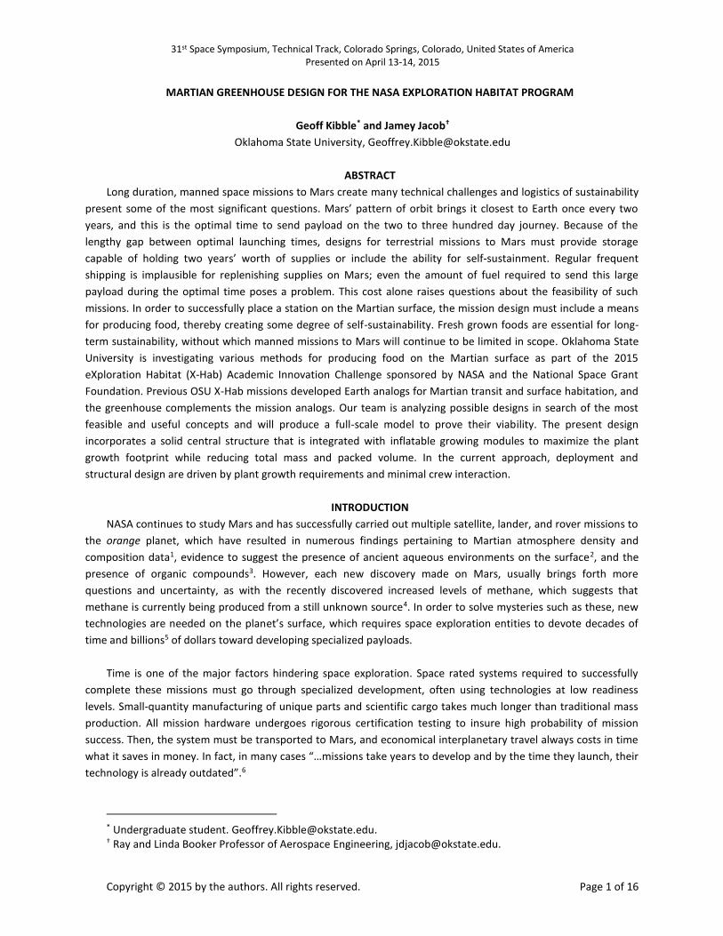
NASA is currently focusing efforts on Deep Space Habitat (DSH) studies. Most notably on the Habitat
Demonstration Unit (HDU) Project (Figure 1), which tests possible habitat concepts, modules, and configurations
for multiple mission destinations, one of which is Mars. The HDU-DSH system is being studied at the D-RATS
(Desert Research and Terrestrial Studies) center in Arizona to test and identify the optimum design and crew size
for various mission requirements.11 The eXploration Habitat (X-Hab) Academic Innovation Challenge, sponsored by
NASA and the National Space Grant Foundation, allows universities to contribute to the development of DSH
systems. Each university team accepted into the X-Hab program works to design a system that fulfills the requests
for a mission proposed by NASA, and then each team constructs an analog prototype to demonstrate and test its
design. The X-Hab Program benefits NASA by producing, demonstrating, and testing multiple design concepts and
approaches to a single problem, which can then be modified, combined, or thrown-out, ultimately increasing the
efficiency of NASA’s design process. Since its inception in 2011, the X-Hab program has become an integral part of
NASA’s HDU-DSH research.
31st Space Symposium, Technical Track, Colorado Springs, Colorado, United States of America Presented on April 13-14, 2015
Page 3 of 16
Figure 1: NASA’s Habitat Demonstration Unit12
The X-Hab Academic Innovation Challenge is in its fifth consecutive year. The 2011 challenge was to design an
inflatable loft to be added to the top of the HDU-DSH system in order to provide habitation functions (Figure 2).13
In the following four competition years, NASA offered multiple projects for which universities could write
proposals.14 These topics ranged from vertical habitat layout, horizontal habitat layout, deployable airlock systems,
robotic systems, various plant growth studies, storage systems, and expandable habitats. In the last five years, the
X-Hab program has produce twenty-four separate university DSH studies, and Oklahoma State University’s
proposals have been selected to participate in the program every year. This year’s design competition is to develop
a method and create a facility for growing food on Mars, which will be a supplemental food source for four
astronauts on a five-hundred-day surface mission. Oklahoma State University’s Organics and Agricultural
Sustainment Inflatable System (OASIS) meets these requirements and provides a realistic solution to the issues
surrounding food production on the Martian surface.

31st Space Symposium, Technical Track, Colorado Springs, Colorado, United States of America Presented on April 13-14, 2015
Page 4 of 16
Figure 2: 2011 Oklahoma State University’s X-Hab Academic Innovation Challenge Inflatable Loft15
MISSION DESIGN
The OASIS greenhouse module (Figure 3) incorporates a solid central structure with four inflatable soft-good
cylindrical tubes expanding outward. The solid central hub is a cylindrical pressure vessel design and shares
similarities with NASA’s HDU and International Space Station (ISS) Modules. The inflatable tube structures are
Greenwings and contain the plant growth systems. The Greenwings use a spacesuit-like design combining multiple
layers of various flexible materials. The entire module will operate at an equalized internal pressure of 60 kpa, to
minimize the structural weight while still supplying appropriate breathable atmosphere composition. Total weight
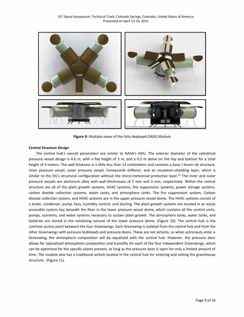
of the final landed model is approximately less than seven tons (Table 4).
Figure 3: OASIS Greenhouse Concept
31st Space Symposium, Technical Track, Colorado Springs, Colorado, United States of America Presented on April 13-14, 2015
Page 5 of 16
Table 1: Estimated Masses of OASIS Systems
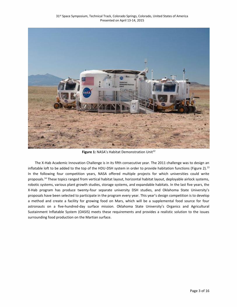
Launch Platform and Interplanetary Transit
NASA’s Space Launch System (SLS), which is currently in development, will deliver OASIS to Low Earth Orbit
(LEO). The SLS is the next generation heavy-lift vehicle that will efficiently put into orbit large-scale systems, which
are needed for humans to accomplish interplanetary travel.16 The capabilities of the SLS are major design drivers,
and the entire OASIS configuration conforms to the required mass and volume constraints. The OASIS stack has a
maximum outer diameter of 4.6 meters and a maximum height of less than 13 meters (Figure 4). The
interplanetary transit module easily fits within the cargo fairing of the SLS and is estimated to have a total mass of
less than 100 Tons. Once the interplanetary transit module is in LEO, OASIS will make the initial delta v burn from a
standard Hohmann transfer maneuver of less than 3 km/s.17 After this initial burn, the OASIS’s Interplanetary
Module will be on a rendezvous trajectory to Mars for 8-9 months (Figure 5).
Figure 4: OASIS Interplanetary Transit Module Size and Visualization of System within the SLS Payload Fairing

31st Space Symposium, Technical Track, Colorado Springs, Colorado, United States of America Presented on April 13-14, 2015
Page 6 of 16
Figure 5: Interplanetary Transit Rendezvous Trajectory from Earth to Mars
Aerobraking, Entry, and Landing
Upon OASIS’s rendezvous with Mars the interplanetary transit module booster stage detaches and the
inflatable heat shield, roughly 15 meters in diameter, will deploy, and an initial aerobraking maneuver will put the
module into a highly elliptical orbit around Mars. Multiple aerobraking passes will reduce orbital velocity and
eventually drop the craft into a suborbital ballistic trajectory at roughly 3.5 km/s.18 Large-scale inflatable heat
shields are currently in development for the purpose of enabling heavier payloads to achieve safer velocities in low
density atmospheres.19 After burning through the thin atmosphere and reducing speed to close to Mach 2, a
supersonic parachute will deploy to slow the craft further.20 Once past the supersonic region, the inflatable heat
shield and supersonic parachutes detach, and the subsonic parachute deploys. At an altitude below 5 km, the
retro-thrusters engage, and the subsonic parachute detaches. The vehicle then uses the retro-thrust to slow to
near zero velocity above the landing zone, while landing struts deploy, and the vehicle makes small adjustments to
the final landing location based on the terrain. Once OASIS has successfully landed, the retro-thrusters detach from
the top of the module and eject themselves from the area. The landing struts then level the module in preparation
for deployment (Figure 6).

31st Space Symposium, Technical Track, Colorado Springs, Colorado, United States of America Presented on April 13-14, 2015
Page 7 of 16
Figure 6: OASIS Entry and Landing Configuration
SYSTEM DESIGN
The design focuses on automation and redundancy, which allows astronauts to devote more mission time to
other research obligations. The OASIS greenhouse module is intended to be a hands-free greenhouse system that
requires only minimal attention. The inflation procedure occurs autonomously, and the entire system activates
prior to astronaut arrival. This will insure that astronauts will have an operating food source when they arrive, and
if a failure does occur, they will have enough advanced warning to decide how to proceed. When the deployment
sequence is activated, OASIS will spring open five garage-door-like solar panel arrays (Figure 7). Then the
Greenwing deployment system utilizes a constant pressure deployment method by integrating four wench
controlled tension cables to stabilize the inflation procedure, by slowly and steadily allowing the volume to
increase until the Greenwings are fully deployed. This cable system will force the endcap to maintain a
perpendicular configuration and a uniform internal pressure, avoiding chaotic uncontrollable inflation that could
result in rupture.21 In consideration of the low outer pressures on the Martian surface and the large diameter of
the inflatable structures, each Greenwing will be extremely stiff. However, for added stability to the entire OASIS
module and the ability to adjust the incline of the Greenwings for water return purposes, the end caps contain
micro-castpiles that anchor into the ground upon deployment (Figure 8). After the green wings are fully deployed,
additional garage-door-like solar panel arrays spring open from the endcaps, which completes the OASIS’s
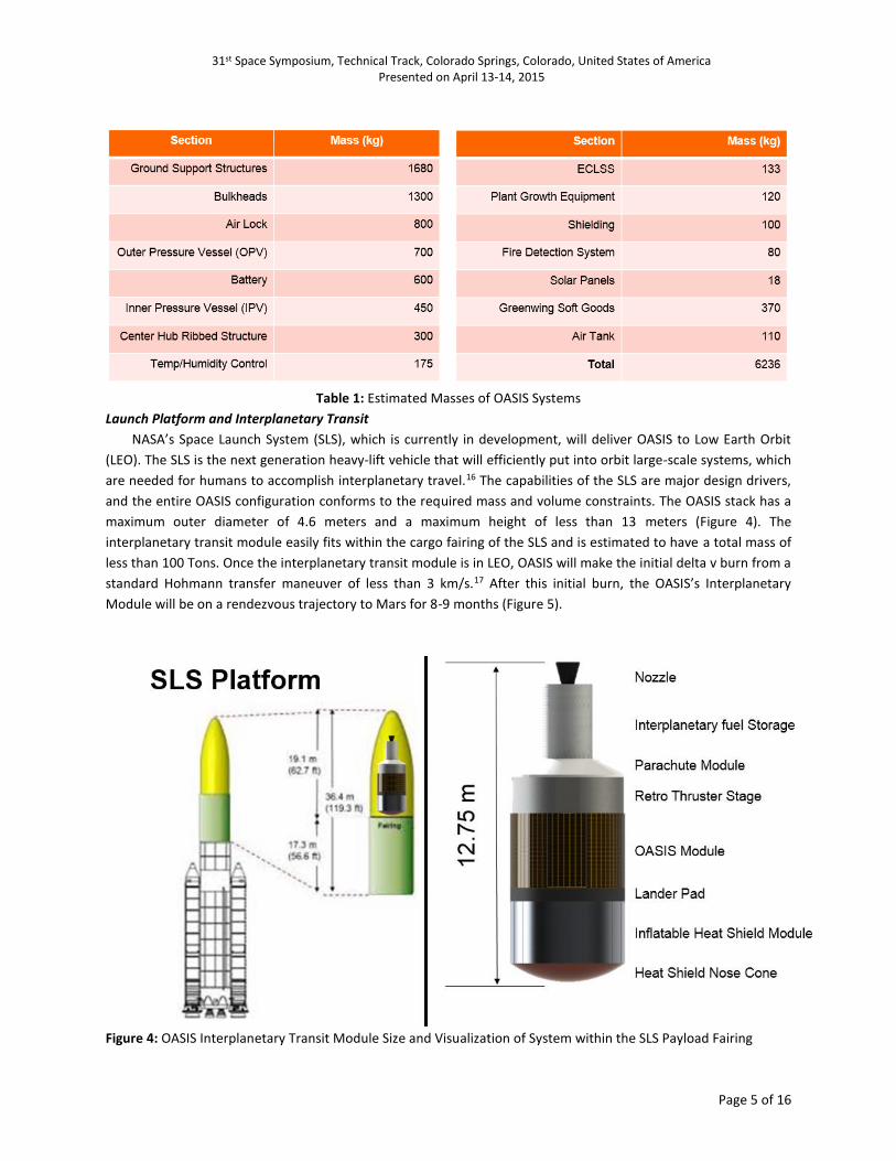
deployment sequence (Figure 9). Once fully deployed OASIS’s widest span is 18 m, maximum height is 5 m, useful
interior volume is 51 m3, and total solar panel area is 97 m2.

31st Space Symposium, Technical Track, Colorado Springs, Colorado, United States of America Presented on April 13-14, 2015
Page 8 of 16
Figure 7: OASIS After Initial deployment of Central Solar Arrays
Figure 8: Greenwing Exterior with Endcap, Axial Deployment Tension Cables, and Micro-Castpiles at the Endcap
31st Space Symposium, Technical Track, Colorado Springs, Colorado, United States of America Presented on April 13-14, 2015
Page 9 of 16
Figure 9: Multiple views of the fully deployed OASIS Module
Central Structure Design
The central hub’s overall parameters are similar to NASA’s HDU. The exterior diameter of the cylindrical
pressure vessel design is 4.6 m, with a flat height of 3 m, and a 0.5 m dome on the top and bottom for a total
height of 4 meters. The wall thickness is a little less than 13 centimeters and contains a basic I-beam rib structure,
inner pressure vessel, outer pressure vessel, honeycomb stiffener, and an insulation-shielding layer, which is
similar to the ISS’s structural configuration without the mirco-meteoroid protective layer.22 The inner and outer
pressure vessels are aluminum alloy with wall thicknesses of 2 mm and 3 mm, respectively. Within the central
structure are all of the plant growth systems, HVAC systems, fire suppression systems, power storage systems,
carbon dioxide collection systems, water tanks, and atmosphere tanks. The fire suppression system, Carbon
dioxide collection system, and HVAC systems are in the upper pressure vessel dome. The HVAC systems consist of
a boiler, condenser, pump, fans, humidity control, and ducting. The plant growth systems are located in an easily
accessible system bay beneath the floor in the lower pressure vessel dome, which contains all the control units,
pumps, nutrients, and water systems necessary to sustain plant growth. The atmosphere tanks, water tanks, and
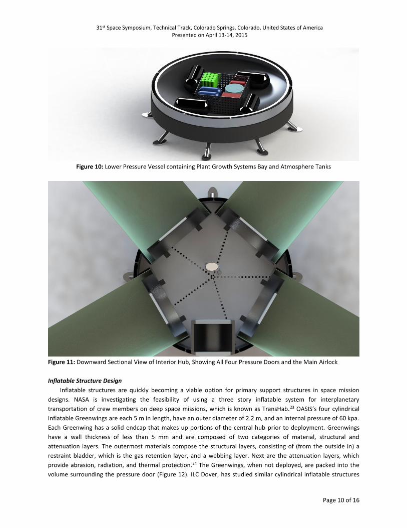
batteries are stored in the remaining volume of the lower pressure dome. (Figure 10). The central hub is the
common access point between the four Greenwings. Each Greenwing is isolated from the central hub and from the
other Greenwings with pressure bulkheads and pressure doors. These are not airlocks, so when astronauts enter a
Greenwing, the atmosphere composition will be equalized with the central hub. However, the pressure door
allows for specialized atmosphere composition and humidity for each of the four independent Greenwings, which
can be optimized for the specific plants present, as long as the pressure door is open for only a limited amount of
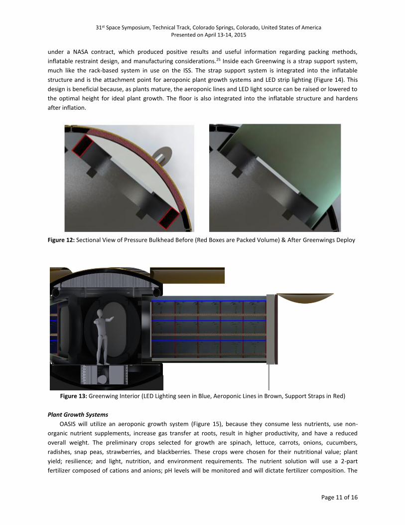
time. The module also has a traditional airlock located in the central hub for entering and exiting the greenhouse
structure. (Figure 11).
31st Space Symposium, Technical Track, Colorado Springs, Colorado, United States of America Presented on April 13-14, 2015
Page 10 of 16
Figure 10: Lower Pressure Vessel containing Plant Growth Systems Bay and Atmosphere Tanks
Figure 11: Downward Sectional View of Interior Hub, Showing All Four Pressure Doors and the Main Airlock
Inflatable Structure Design
Inflatable structures are quickly becoming a viable option for primary support structures in space mission
designs. NASA is investigating the feasibility of using a three story inflatable system for interplanetary
transportation of crew members on deep space missions, which is known as TransHab.23 OASIS’s four cylindrical
Inflatable Greenwings are each 5 m in length, have an outer diameter of 2.2 m, and an internal pressure of 60 kpa.
Each Greenwing has a solid endcap that makes up portions of the central hub prior to deployment. Greenwings
have a wall thickness of less than 5 mm and are composed of two categories of material, structural and
attenuation layers. The outermost materials compose the structural layers, consisting of (from the outside in) a
restraint bladder, which is the gas retention layer, and a webbing layer. Next are the attenuation layers, which
provide abrasion, radiation, and thermal protection.24 The Greenwings, when not deployed, are packed into the
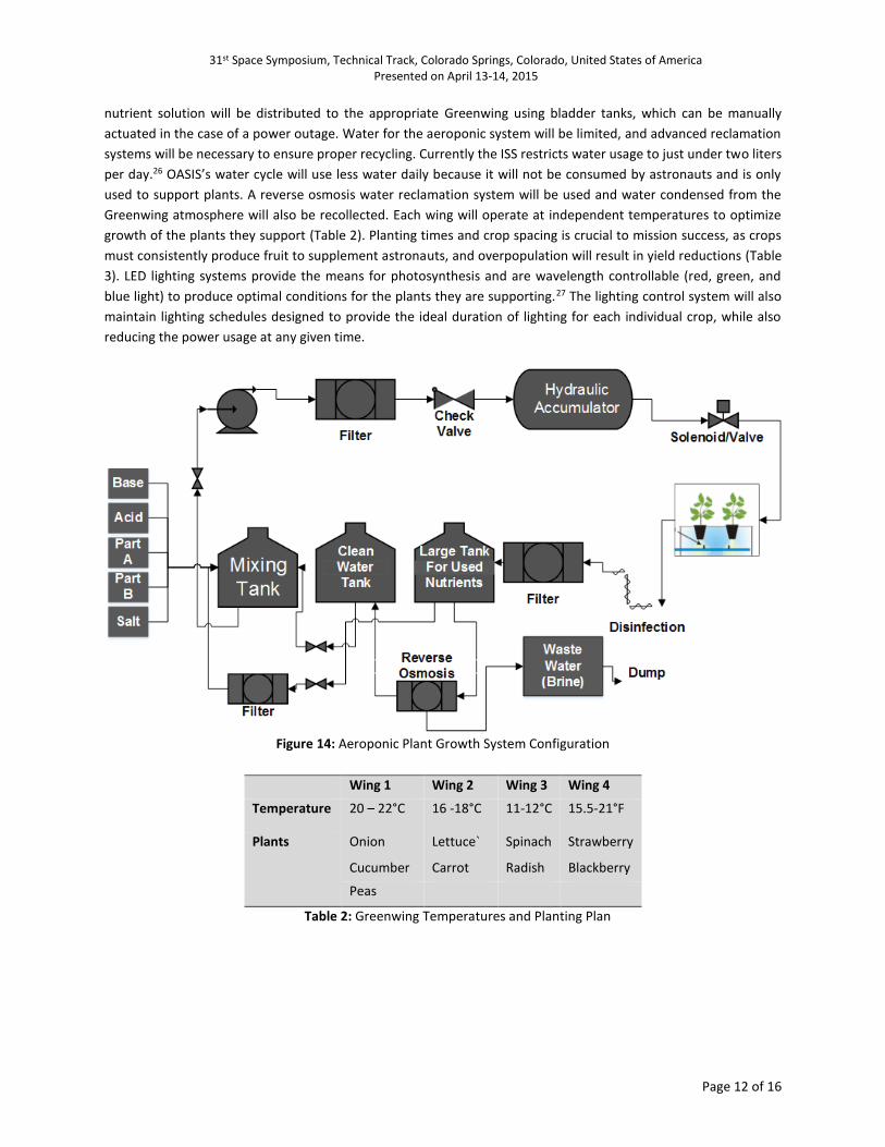
volume surrounding the pressure door (Figure 12). ILC Dover, has studied similar cylindrical inflatable structures
31st Space Symposium, Technical Track, Colorado Springs, Colorado, United States of America Presented on April 13-14, 2015
Page 11 of 16
under a NASA contract, which produced positive results and useful information regarding packing methods,
inflatable restraint design, and manufacturing considerations.25 Inside each Greenwing is a strap support system,
much like the rack-based system in use on the ISS. The strap support system is integrated into the inflatable
structure and is the attachment point for aeroponic plant growth systems and LED strip lighting (Figure 14). This
design is beneficial because, as plants mature, the aeroponic lines and LED light source can be raised or lowered to
the optimal height for ideal plant growth. The floor is also integrated into the inflatable structure and hardens
after inflation.
Figure 12: Sectional View of Pressure Bulkhead Before (Red Boxes are Packed Volume) & After Greenwings Deploy
Figure 13: Greenwing Interior (LED Lighting seen in Blue, Aeroponic Lines in Brown, Support Straps in Red)
Plant Growth Systems
OASIS will utilize an aeroponic growth system (Figure 15), because they consume less nutrients, use non-
organic nutrient supplements, increase gas transfer at roots, result in higher productivity, and have a reduced
overall weight. The preliminary crops selected for growth are spinach, lettuce, carrots, onions, cucumbers,
radishes, snap peas, strawberries, and blackberries. These crops were chosen for their nutritional value; plant
yield; resilience; and light, nutrition, and environment requirements. The nutrient solution will use a 2-part
fertilizer composed of cations and anions; pH levels will be monitored and will dictate fertilizer composition. The
31st Space Symposium, Technical Track, Colorado Springs, Colorado, United States of America Presented on April 13-14, 2015
Page 12 of 16
nutrient solution will be distributed to the appropriate Greenwing using bladder tanks, which can be manually
actuated in the case of a power outage. Water for the aeroponic system will be limited, and advanced reclamation
systems will be necessary to ensure proper recycling. Currently the ISS restricts water usage to just under two liters
per day.26 OASIS’s water cycle will use less water daily because it will not be consumed by astronauts and is only
used to support plants. A reverse osmosis water reclamation system will be used and water condensed from the
Greenwing atmosphere will also be recollected. Each wing will operate at independent temperatures to optimize
growth of the plants they support (Table 2). Planting times and crop spacing is crucial to mission success, as crops
must consistently produce fruit to supplement astronauts, and overpopulation will result in yield reductions (Table
3). LED lighting systems provide the means for photosynthesis and are wavelength controllable (red, green, and
blue light) to produce optimal conditions for the plants they are supporting.27 The lighting control system will also
maintain lighting schedules designed to provide the ideal duration of lighting for each individual crop, while also
reducing the power usage at any given time.
Figure 14: Aeroponic Plant Growth System Configuration
Wing 1 Wing 2 Wing 3 Wing 4
Temperature 20 – 22°C 16 -18°C 11-12°C 15.5-21°F
Plants Onion Lettuce` Spinach Strawberry
Cucumber Carrot Radish Blackberry
Peas
Table 2: Greenwing Temperatures and Planting Plan

31st Space Symposium, Technical Track, Colorado Springs, Colorado, United States of America Presented on April 13-14, 2015
Page 13 of 16
Plant Greenwing
Number
Required Spacing
(cm)
Time to maturity (Days) Planting Interval
(Days)
Snap Peas 1 15.24 60 2
Cucumber 1 30.5 70 2
Onion 1 15.24 120 4
Lettuce 2 15.24 60 1
Carrots 2 7.62 70 1
Spinach 3 10.16 60 3
Radish 3 15.24 35 2
Strawberry 4 91.4 - -
Blackberry 4 121.9 - -
Table 3: Greenwing Planting Plan with Plant Spacing, Time to Maturity, and Planting Intervals for Each Crop
Power Collection Systems
The solar power collection system incorporates large rigid solar panel arrays, flexible solar panels integrated
into the top sun exposed portions of the inflatable Greenwings, and battery systems to store the collected power.
Flexible solar panels have been tested in previous Oklahoma State University projects and have been successfully
demonstrated in inflatable configurations (Figure 15). Initial calculations of average solar power collection show,
with OASIS’s 97 m2 of solar panel area, solar panel efficiencies of 40%, and average solar irradiances of 590 W/m2
could provide as much as 25 kW of power.28 However, this number is calculated using ideal conditions and should
be taken as a maximum; during sand storms, this value could be reduced by as much as 95%. A rough estimate of
OASIS’s power consumption budget totals over 22 kw of power. This is below the Ideal maximum power collection;
however, the power consumption value is estimated as a constant. Therefore, unless more solar panel area is
added, solar panel efficiency is increased, or power consumption is reduced, the module will most likely run into
power management issues. Adding more solar panel surface area is a feasible option and rough calculations show
that simple folding solar arrays, like those used on the Curiosity Rover mission, could increase maximum solar
power collection by 10 kW, which is more reasonable.
Figure 15: Flexible Solar Panels Successfully Incorporated with an Inflatable Design in a High Altitude Test30
31st Space Symposium, Technical Track, Colorado Springs, Colorado, United States of America Presented on April 13-14, 2015
Page 14 of 16
TESTING METHODOLOGY
In order to demonstrate and test the methods used by the OASIS design, full-scale analog and multiple small-
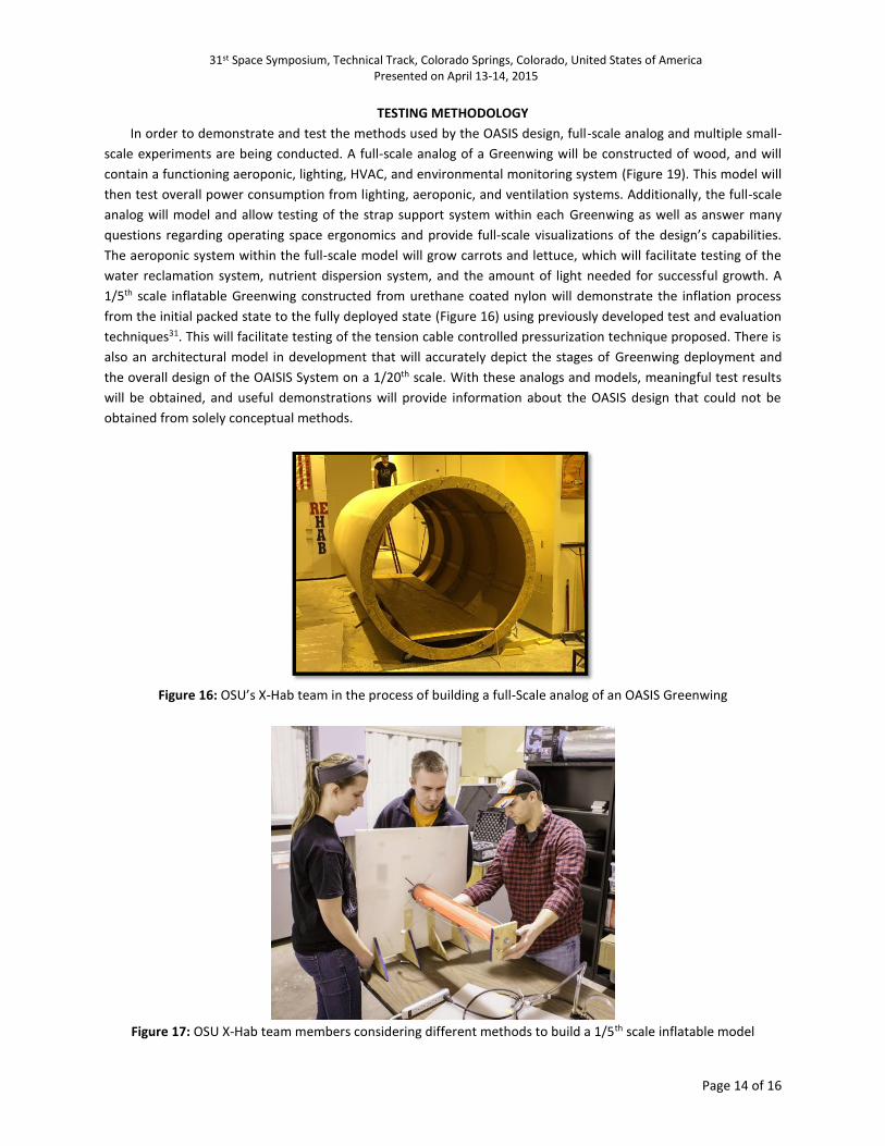
scale experiments are being conducted. A full-scale analog of a Greenwing will be constructed of wood, and will
contain a functioning aeroponic, lighting, HVAC, and environmental monitoring system (Figure 19). This model will
then test overall power consumption from lighting, aeroponic, and ventilation systems. Additionally, the full-scale
analog will model and allow testing of the strap support system within each Greenwing as well as answer many
questions regarding operating space ergonomics and provide full-scale visualizations of the design’s capabilities.
The aeroponic system within the full-scale model will grow carrots and lettuce, which will facilitate testing of the
water reclamation system, nutrient dispersion system, and the amount of light needed for successful growth. A
1/5th scale inflatable Greenwing constructed from urethane coated nylon will demonstrate the inflation process
from the initial packed state to the fully deployed state (Figure 16) using previously developed test and evaluation
techniques31. This will facilitate testing of the tension cable controlled pressurization technique proposed. There is
also an architectural model in development that will accurately depict the stages of Greenwing deployment and
the overall design of the OAISIS System on a 1/20th scale. With these analogs and models, meaningful test results
will be obtained, and useful demonstrations will provide information about the OASIS design that could not be
obtained from solely conceptual methods.
Figure 16: OSU’s X-Hab team in the process of building a full-Scale analog of an OASIS Greenwing
Figure 17: OSU X-Hab team members considering different methods to build a 1/5th scale inflatable model

31st Space Symposium, Technical Track, Colorado Springs, Colorado, United States of America Presented on April 13-14, 2015
Page 15 of 16
FUTURE STUDY
Moving forward, the Oklahoma State University Space Cowboy’s would like to further investigate methods to
reduce power consumption of the OASIS module. One option is to use natural light collection and transportation
for all or partial plant photosynthesis. One study suggests that a natural light collection system is capable of
providing nearly an additional kilowatt of effective lighting power for a lunar application.29 This could reduce
power requirements substantially. Additionally, the largest consumer of power within the OASIS greenhouse are
the HVAC systems which accounted for more than half the overall power consumption. Newer technology could
result in slightly more efficient systems, which could be the difference between missions to Mars becoming
feasible or remaining science fiction.
ACKNOWLEDGMENTS
Our team extends a special thanks to the NASA engineers and scientists managing the eXploration Habitat
Academic Innovation Challenge for providing their time and research facilities. Also, the author would like to thank
the National Space Grant Foundation and the Oklahoma Space Grant Consortium for funding support. Additionally,
the authors wish to acknowledge the efforts of the 2014-2015 Space Cowboys X-Hab team, which includes many
student members too numerous to list. Finally, our team wishes to thank Drs. Steve O’Hara, Paul Weckler, and
Ning Wang for their guidance and support through this entire process and OK LSAMP for additional support.
1 Mazarico, Erwan. et al. “Atmospheric Density During the Aerobraking of Mars Odyssey from Radio Tracking
Data.” Journal of Spacecraft and Rockets 44, no. 6 (2007): 1165-1171. 2 Arvidson, R. et al. “ Ancient Aqueous Environments at Endeavour Crater, Mars.” Science 343, 2014 3 Ming, D. et al. “ Volatile and Organic Compositions of sedimentary Rocks in Yellowknife Bay, Gale Crater,
Mars.” Science 343, 2014 4 Webster, Christopher. et al. “Mars Methane Detection and Variability at Gale Crater.” Science 347, no. 6220,
2015. 5 National Aerospace and Space Administration. FY 2013 President’s Budget Request Summery. “Mars
Exploration.” PS-39. 6 Dillow, Clay. “Curiosity’s Legacy: What this Week’s Successful Landing Means for the Future of Robotic Space
Exploration.” Popular Science. Last Modified August 10, 2012. http://www.popsci.com/technology/article/2012-08/curiositys-legacy-what-sundays-successful-landing-means-future-robotic-space-exploration
7 “Benefits from Apollo: Giant Leaps in Technology.” NASA Facts 07, no. 2 (2004) 8 Arnold, Patricia. et al. “The Case for Space Exploration.” Space Foundation. Accessed March 3rd: 22
http://astro.cornell.edu/~randerson/TheCaseForSpace.pdf 9 Tito, Dennis. et al. “Feasibility Analysis for a Manned Mars Free-Return Mission in 2018.” Presentation at the
IEEE Aerospace Conference, Big Sky, MT, March 2-9, 2013 10 Do, Sydney. et al. “An Independent Assessment of the Technical Feasibility of the Mars One Mission Plan.”
Presentation at the 65th International Astronautical Congress, Toronto, Canada, September 29 – October 3, 2014. 11 “Habitat Demonstration Unit-Deep Space Habitat.” NASA Facts 47, no. 8, (2011) http://www.nasa.gov/ pdf/468441main_HDU_FactSheet_508.pdf 12 “What is Desert RATS?” NASA: Desert RATS Education. http://ares.jsc.nasa.gov/education/drats/drats.cfm 13 Gill, Tracy. et al. ”Integration Process for the Habitat Demonstration Unit.” Presentation at the AIAA Space
Conference, Long Beach, CA, September 26-29, 2011. 14 Howe, A. et al. “NASA Habitat Demonstration Unit (HDU) Deep Space Habitat Analog.” Presentation at the
AIAA Space Conference, San Diego, CA, September 10-12, 2013. 15 “Oklahoma State University Team Assembles X-Hab Challenge Loft.” NASA. http://www.nasa.gov/
exploration/technology/deep_space_habitat/xhab/oklahoma-state-2011.html
31st Space Symposium, Technical Track, Colorado Springs, Colorado, United States of America Presented on April 13-14, 2015
Page 16 of 16
16 “Space Launch System.” NASA Facts 59, no. 6 (2012) www.nasa.gov/pdf/664158main_sls_fs_master.pdf 17 Wiesel, William. Space Flight Dynamics. Yalonda: Aphelion Pres, 2010. 18 Forget, Francois. et al. “A Simple Analytical Equation to Calculate the Atmospheric Drag During Aerobraking
Campaigns.” Professional Presentation, Dynamic Meteorology Laboratory (LDM/CNRS), 2010 19 “ Inflatable Re-entry Vehicle Experiment.” NASA Facts (2009) www.nasa.gov/pdf/378699main_NASAFacts-
IRVE.pdf 20 Braun, Robert. et al. “Mars Exploration Entry, Descent, and Landing Challenges.” Presentation at the IEEE
Aerospace Conference, Big Sky, MT, March 4-11, 2006. 21 Cadogan, David. et al. “Deployment Control Mechanisms for Inflatable Space Structures.” Presented at the
33rd Aerospace Mechanism Conference, Pasadena, CA, May 19-21, 1999. 22 Patrick, Barry. “Home, Space Home.” NASA Science News. March 14, 2001. http://science.nasa.gov/science-
news/science-at-nasa/2001/ast14mar_1/ 23 Kennedy, Kriss. et al. “Inflatable Habitats.” AIAA Publication (2000): 527-552 24 Hinkle, Jon. “Structural Design, Analysis, and Testing of an Expandable Lunar Habitat.” Presentation at the
AIAA Structure Dynamics and Materials Conference, Palm Springs, CA, May 4-7, 2009. 25 Hinkle, Jon. et al. “Deployment testing of an Expandable Lunar Habitat.” Presentation at AIAA Space
Conference, Pasadena, CA, September 14-17, 2009. 26 Wickman, Leslie. “Water Reclamation for Remote Environments: an Ecologically Sound Approach.”
Presentation at 45th AIAA Aerospace Sciences Meeting, Reno, NV, January 8-11, 2007. 27 Prikupets, L. et al. “Optimization of Lamp Spectrum for Vegetable Growth.” a short report, Institute of
Biophysics, Siberian Branch of Academy of Sciences of Russia, 1993. 28 James, George. et al. “Surviving on Mars without Nuclear Energy” MarsPapers 58, (1998): 586 29 Furfaro, Robert. et al. “Fresnel-based Solar Concentration Power System for Mars and Lunar Outposts.”
Presentation at 44th International Conference on Environmental Systems, Tucson, AZ, July 13-17, 2014. 30 Chandler, J. & Jacob, J. D. “Design and Flight Testing of a Mars Aircraft Prototype Using Inflatable Wings.”
58th International Astronautical Conference, Hyderabad, India, Sep. 24, 2007. 31 Hill, Jeremy and Jacob, J. “Deployment Dynamics of Inflatable Space Habitats,” AIAA- 2010-0000, 48th AIAA
Aerospace Sciences Meeting Including the New Horizons Forum and Aerospace Exposition, Orlando, Florida, Jan. 4-7, 2010.