marley series 10 cooling tower - bid on equipment files/spx - marley series 10 cooling...
TRANSCRIPT

/ Marley Series 10 Cooling Tower /

Marley / Series 10 Cooling Tower / Table of Contents
Engineering Data
Schematic 6Concrete Basin 7Support 8Inlet Piping 9
Specifications / Base
Base 10Thermal Performance 11Construction 12Fan Deck and Fan Cylinder 13Mechanical Equipment 14Fill 15Drift Eliminators 15Hot Water Distribution System 16Casing and Louvers 16Access and Safety 16Cold Water Basin 17Scope of Work 17
Specifications / Options
Control OptionsControl System 18Basin Heater 19Variable Speed Drive 19Vibration Limit Switch 20
Convenience and Safety OptionsStairway 21Plenum Walkway 21Ladder Extension 21Ladder Safety Cage 22Oil Level Sight Glass 22
Miscellaneous OptionsWood Cold Water Basin 22PVC Fill Splash Bars 23Redwood Components 23Hot Water Basin Covers 23Air Inlet Screens 23Watertight Partitions Between Cells 23FRP Louvers 24Low Noise Tower 24Fire Safety Options 25

Marley / Series 10 Cooling Tower / 4
n Fill and Fan Combinations are mutually supportive for maximum thermal performance in system configuration.
n Nozzles and Water Distribution systems provide uniform fill coverage without excessive contribution to air pressure losses.
n The Geareducer® provides consistently optimum fan speeds, and operates reliably in a saturated air/vapor mixture of corrosive nature.
n Fan Motors are designed to Marley specifications for extra demands of cooling tower duty. Motors are insulated with extra protection from moisture.
n Driveshafts are designed to absorb operational shock loads, thereby increasing the service life of these critical components.
Since 1922, customers have trusted the Marley brand for high quality, dependable products.
The principle reason for this reputation is our recognition that each component of a cooling tower must perform at its peak—and all work compatibly toward overall efficiency.
Accordingly, each performance-related component of a Marley cooling tower is designed and manu-factured in the context of the overall cooling tower system.
n Fan Design is optimized for the static pressure imposition and airflow requirements of the tower.
n Fan Cylinders and their associated eased inlets, augment fan operation.
n Single-source parts availability. All tower components except the electric motors are designed, manufactured, guaranteed, and stocked by Marley. You always know who to call for any parts you need. You're also assured that all components of the cooling tower will work together, because they were designed to work together!
n Flexible Cooling Capacity. Twenty-four tower models with capacities to 6720 GPM per fan cell, provide the flexibility to fit almost any job. Greater capacity is available with multiple fan-cells.
n Extremely Low Drift. XCEL®plus drift eliminators really get rid of the costly nuisance of drift spotting on objects around the tower. The corrosion resistance of PVC assures you that you’ll probably never have to replace eliminators for the life of the tower.
n Longer Service Life. Pressure-treated Douglas fir structure and splash-fill bars, FRP fill support grids, PVC drift eliminators, and all other tower components are designed for years of service.
n Lower operating costs. Adjustable pitch fans with true airfoil blades and 98% efficient Geareducer drive assure maximum utilization of applied fan power. Computer optimized fill configurations and low pressure-drop drift eliminators afford maximum cooling with minimum power input. Gravity flow water distribution minimizes pump power requirements.
n Lower maintenance costs. Heavy-duty aluminum alloy fans, cast-iron Geareducers, and stainless steel driveshafts require only periodic maintenance. Low-maintenance materials are used throughout the cooling tower. Wide-spaced splash-fill helps prevent clogging. The fill area is readily accessible for cleaning.
n Five-year drivetrain warranty. What other manufacturer will guarantee your tower's mechanical equipment for five full years? You'll save valuable equipment maintenance dollars.
n Proven Performance. SPX Cooling Technologies stands by its responsibility for reliable thermal performance. We designed it. We rate it. We guarantee it!
/ The Marley Difference /
/ The Quality Advantage /

Marley / Series 10 Cooling Tower / 5
Pages 10 through 17 indicate those paragraphs which will result in the purchase of a cooling tower which will not only accomplish the specified thermal performance, but which will include normal operation and maintenance-enhancing accessories and features. It will also incorporate those standard materials which testing and experience has proven to provide best results in normal operating conditions.Pages 18 through 25 provide some paragraphs intended to add those features, components, and materials that will customize the tower to meet the user's requirements. Space does not permit definition and explanation of all of the possible options that can be applied to the Series 10. We realize that you, the purchaser, must be happy with the tower‘s characteristics, and we are prepared to provide—or provide for—any reasonable enhancement that you are willing to define and purchase.Your needs will become part of the continuing evolution of this Marley product line.
The Series 10 is a field-erected, splash fill, crossflow, wood cooling tower, designed to
serve all normal cooling water systems—as well as those “dirty water” systems which would place the long term operation of a film fill tower in jeopardy. The Series 10 is evolved from the crossflow concept of cooling towers pioneered by Marley in 1938, incorporating over 70 years of design advancements that our customers have found valuable.This publication not only relates the language to use in describing an appropriate Series 10 cooling tower—but also defines why certain items and features are important enough to specify with the intention of insisting upon compliance by all bidders. The left hand column of pages 10 through 25 provides appropriate text for the various specification paragraphs, whereas the right hand column comments on the meaning of the subject matter and explains its value.

Marley / Series 10 Cooling Tower / Engineering Data : Schematic 6
NOTE
1 The last number of the model indicates number of cells. Change as appropriate for your selection.
2 Overall length of the tower is: fan cells × L + 8. Primary engineer-ing data is per cell.
3 Tower installations with an elevation of 20'-0" or more from top of the tower fan deck to the grade or roof level require a safety cage on the tower ladder in accordance with OSHA standards. Safety cage is an available option.
4 All tower installations require a minimum of 4'-0" from the tower endwall to any vertical obstruction at the tower ladder location.
5 Use this bulletin for preliminary layouts only. Do not use for construction. Obtain current drawings from your Marley sales representative.
L
4"
4"
6 1/4"
BASE OFPERIMETERTOWER COLUMNS
TOP OF SUPPORTINGSTEEL
TOP OF PERIMETERGUARDRAIL
H
W
Plan Endwall Elevation
Tower ModelNote 1
GPMper cell
Dimensions
L W H Fan Diameter
361-101 135-1000 8'-0" 19'-2" 10'-101⁄4" 72"
362-101 165-1235 8'-0" 21'-2" 10'-101⁄4" 72"
363-101 135-1000 8'-0" 19'-2" 12'-101⁄4" 72"
364-101 165-1235 8'-0" 21'-2" 12'-101⁄4" 72"
365-101 190-1455 8'-0" 23'-2" 12'-101⁄4" 72"
366-101 205-1500 12'-0" 21'-2" 10'-101⁄4" 96"
367-101 245-1850 12'-0" 23'-2" 10'-101⁄4" 96"
368-101 205-1500 12'-0" 21'-2" 12'-101⁄4" 96"
369-101 245-1850 12'-0" 23'-2" 12'-101⁄4" 96"
370-101 285-2185 12'-0" 25'-2" 12'-101⁄4" 96"
371-101 270-2000 16'-0" 21'-2" 12'-101⁄4" 96"
372-101 325-2465 16'-0" 23'-2" 12'-101⁄4" 96"
373-101 380-2910 16'-0" 25'-2" 12'-101⁄4" 96"
374-101 340-2500 20'-0" 23'-2" 12'-101⁄4" 120"
375-101 410-3080 20'-0" 25'-2" 12'-101⁄4" 120"
376-101 475-3640 20'-0" 27'-2" 12'-101⁄4" 120"
CAUTIONThe cooling tower must be located at such distance and direction to avoid the possibility of contaminated tower discharge air being drawn into building fresh air intake ducts. The purchaser should obtain the services of a Licensed Professional Engineer or Registered Architect to certify that the location of the tower is in compliance with applicable air pollution, fire, and clean air codes.

Marley / Series 10 Cooling Tower / Engineering Data : Concrete Basin 7
NOTE
1 Use this bulletin for preliminary layouts only. Do not use for construction. Obtain current drawings from your Marley sales representative.
2 Tower weight is total wet operating weight of tower only excluding water in concrete basin.
3 Purchaser to design, construct and furnish concrete basin com-plete to suit the general dimensions of current Marley drawings.
4 Last number of model indicates number of cells. Change as appro-priate for your selection. Primary engineering data is per cell.
5 All anchor bolts complete with nut and washer will be furnished by others. Bolts are to be 1⁄2" diameter with 11⁄2" all thread projection.
6 Maintain no less than 2'-0" of clear space at tower endwalls for construction purposes. Louvered faces must have unobstructed air supply. If obstructions exist nearby, consult your Marley sales representative.
7 Other contractors or purchaser must design, locate, construct, and furnish sump(s) and overflow(s) to suit requirements. The sump(s) should be designed according to the pump manufacturer’s recommendations. Other design sources: ANSI/HI specifications 1.1-1.5 for centrifugal pumps, 2.1-2.5 for vertical pumps, and 9.8 for pump intake design.
Plan
6 1/2" OPERATING WATERLEVEL RECOMMENDED
11 1/2"
Section–Flat Slab Basin
11 1/2" 6 1/2" OPERATING WATERLEVEL RECOMMENDED
Section–Deep Basin
Tower ModelNote 4
Dimensions Operating Weight lb
L W A Single Fan Cell Each Cell Add
361-101 8'-0" 15'-0" 2 9240 7880
362-101 8'-0" 17'-0" 2 10660 9160
363-101 8'-0" 13'-0" 2 11210 9580
364-101 8'-0" 15'-0" 2 12690 10780
365-101 8'-0" 17'-0" 2 14210 12140
366-101 12'-0" 17'-0" 3 13380 11820
367-101 12'-0" 19'-0" 3 15440 13740
368-101 12'-0" 15'-0" 3 16260 14370
369-101 12'-0" 17'-0" 3 18340 16170
370-101 12'-0" 19'-0" 3 20540 18210
371-101 16'-0" 15'-0" 4 20280 18400
372-101 16'-0" 17'-0" 4 23010 20840
373-101 16'-0" 19'-0" 4 25870 23560
374-101 20'-0" 17'-0" 5 25700 23650
375-101 20'-0" 19'-0" 5 29060 26700
376-101 20'-0" 21'-0" 5 32580 30100
SUMPSEE NOTE 7
W
A S
PACE
S A
T 4'
0" =
L
6" MIN TYP
OPTIONALPARTITION WALL

Marley / Series 10 Cooling Tower / Engineering Data : Wood Basin 8
Tower ModelNote 4
Dimensions Operating Weight lb
L W A B C Single Fan Cell Each Cell Add
361-101 8'-0" 15'-51⁄2" 2 5'-1" 4'-0" 13980 11880
362-101 8'-0" 17'-51⁄2" 2 6'-1" 4'-0" 15990 13660
363-101 8'-0" 14'-11⁄2" 2 5'-1" 2'-8" 15520 13240
364-101 8'-0" 16'-11⁄2" 2 6'-1" 2'-8" 17640 14960
365-101 8'-0" 18'-11⁄2" 2 7'-1" 2'-8" 19720 16800
366-101 12'-0" 17'-51⁄2" 3 5'-1" 6'-0" 20960 18570
367-101 12'-0" 19'-51⁄2" 3 6'-1" 6'-0" 23880 21270
368-101 12'-0" 16'-11⁄2" 3 5'-1" 4'-8" 23240 20610
369-101 12'-0" 18'-11⁄2" 3 6'-1" 4'-8" 26220 23190
370-101 12'-0" 20'-11⁄2" 3 7'-1" 4'-8" 29240 25980
371-101 16'-0" 16'-11⁄2" 4 5'-1" 4'-8" 29390 26760
372-101 16'-0" 18'-11⁄2" 4 6'-1" 4'-8" 33260 30240
373-101 16'-0" 20'-11⁄2" 4 7'-1" 4'-8" 37230 33960
374-101 20'-0" 18'-11⁄2" 5 5'-1" 6'-8" 38300 35400
375-101 20'-0" 20'-11⁄2" 5 6'-1" 6'-8" 42940 39650
376-101 20'-0" 22'-11⁄2" 5 7'-1" 6'-8" 48100 44550
NOTE
1 Use this bulletin for preliminary layouts only. Do not use for construction. Obtain current drawings from your Marley sales representative.
2 Operating weights include 5" of water in the collection basin. This is the recommended operating water level. Total collection basin depth is 111⁄8".
3 Purchaser to design, construct and furnish tower support complete to suit the general dimensions of current Marley drawings.
4 Last number of model indicates number of cells. Change as appro-priate for your selection. Primary engineering data is per cell.
5 If steel beams are used, they must include 5⁄8" diameter holes to accept 1⁄2" diameter anchor bolts provided.
6 If concrete beams or walls are used, 1⁄2" diameter anchor bolts with 8" projection and 2" minimum thread must be provided by the contractor or purchaser. Bolts must be imbedded in the concrete.
7 Maintain no less than 2'-0" of clear space at tower endwalls for construction purposes. Louvered faces must have unobstructed air supply. If obstructions exist nearby, consult your Marley sales representative.
8 Except for "W" overall of wood basin, all dimensions are to the centerline of the anchor bolts.
A SPACES AT 4' 0" = L
W O
VERA
LL O
F W
OO
D BA
SIN
B
B
CSUMP
OVERFLOW
7 3/4"
7 3/4"
Plan
4" MIN.
NORMALGAGE
8"
Section–Concrete Beam
Section–Steel Beam

Marley / Series 10 Cooling Tower / Engineering Data : Inlet Piping 9
E
C DTYPICAL MULTI-CELL
FACE OF A DIAINLET FLANGE
G MIN
CL CL CL
C L
COLUMN INLET
TOW
ER
INLET
E FACE OF A DIAINLET FLANGE
H TO BASEOF PERIMETERTOWER COLUMNS
B DIA FLOWCONTROL VALVE
B DIACROSSOVER PIPE
B DIA FLOWCONTROL VALVE
LC
LC TOWER
Section–Distribution System
Typical Plan–Side Inlet
Tower Model
GPMPer Cell
Dimensions
A B C D E F G H
361-101 135-1000 8" 6" 4'-0" 8'-0" 7'-1" 8'-103⁄4" 10'-7" 7'-101⁄2"
362-101 165-1235 8" 6" 4'-0" 8'-0" 7'-1" 9'-103⁄4" 11'-7" 7'-101⁄2"
363-101 135-1000 8" 6" 4'-0" 8'-0" 7'-1" 8'-103⁄4" 10'-7" 9'-101⁄2"
364-101 165-1235 8" 6" 4'-0" 8'-0" 7'-1" 9'-103⁄4" 11'-7" 9'-101⁄2"
365-101 190-1455 8" 6" 4'-0" 8'-0" 7'-1" 10'-103⁄4" 12'-7" 9'-101⁄2"
366-101 205-1500 10" 8" 6'-0" 12'-0" 8'-2" 9'-103⁄4" 11'-7" 7'-101⁄2"
367-101 245-1850 10" 8" 6'-0" 12'-0" 8'-2" 10'-103⁄4" 12'-7" 7'-111⁄2"
368-101 205-1500 10" 8" 6'-0" 12'-0" 8'-2" 9'-103⁄4" 11'-7" 9'-111⁄2"
369-101 245-1850 10" 8" 6'-0" 12'-0" 8'-2" 10'-103⁄4" 12'-7" 9'-111⁄2"
370-101 285-2185 10" 8" 6'-0" 12'-0" 8'-2" 11'-103⁄4" 13'-7" 9'-111⁄2"
371-101 270-2000 10" 8" 8'-0" 16'-0" 8'-2" 9'-103⁄4" 11'-7" 9'-111⁄2"
372-101 325-2465 10" 8" 8'-0" 16'-0" 8'-2" 10'-103⁄4" 12'-7" 9'-111⁄2"
373-101 380-2910 10" 8" 8'-0" 16'-0" 8'-2" 11'-103⁄4" 13'-7" 9'-111⁄2"
374-101 340-2500 12" 10" 10'-0" 20'-0" 9'-21⁄4" 10'-103⁄4" 12'-7" 10'-01⁄2"
375-101 410-3080 12" 10" 10'-0" 20'-0" 9'-21⁄4" 11'-103⁄4" 13'-7" 10'-01⁄2"
376-101 475-3640 12" 10" 10'-0" 20'-0" 9'-21⁄4" 12'-103⁄4" 14'-7" 10'-01⁄2"
NOTE
1 Use this bulletin for preliminary layouts only. Do not use for construction. Obtain current drawings from your Marley sales representative.
2 Pumping head contributed by the tower is static life "H". Actual pumping head will vary according to tower circulating GPM. Total pumping head will be furnished at time of proposal.
3 Header should be located opposite fan motor when possible for better distribution of tower loads.
4 Supports on tower for header and crossover pipe are part of the tower design. Riser piping must be supported externally.
5 Marley piping terminates at the face of a cast iron flat face flange. Inlet and bolt circle dimensions conform to class 125 lb. ANSI specifications.
6 If your application requires a bypass system, recommended location is through tower endwall into plenum area. Review of the system by SPX Cooling Technologies engineering is required.

Specifications Specification Value
Marley / Series 10 Cooling Tower / Specifications: Base
1.0 Base:
1.1 Furnish and install an induced-draft, crossflow-type, field-erected, wood-framed, splash fill, industrial-duty cool-ing tower of _____ cell(s), as shown on Plans. The limiting overall dimensions of the tower shall be _____ wide, _____ long, and _____ high to the top of the fan cylinder. Total operating horsepower of all fans shall not exceed ____ hp, consisting of ___ @ _____ hp motor(s). Tower shall be similar and equal in all respects to Marley Model _______.
■ Your specification base establishes the type, configuration, base mate-rial, and physical limitations of the cooling tower to be quoted. During the planning and layout stages of your project, you will have focused your attention on a cooling tower selection that fits your space allot-ment, and whose power usage is acceptable. Limitations on physical size and total operating horsepower avoid the introduction of unfore-seen operational and site-related influences. Specifying the number of cells, and the maximum fan hp/cell will work to your advantage. Crossflow towers are noted for the accessibility and maintainability of all operating components. The spacious interior provides easy access to fill, drift eliminators, all basin accessories—and is one of two primary access ways to the fan, Geareducer®, and other mechanical compo-nents. At the fan deck level, the hot water distribution basins are easily inspected and cleaned—while the tower is operating, if you wish. The mechanical equipment can also be readily accessed from this level. Except for the cold water basin, no counterflow tower component requiring routine maintenance is as easily accessed. The confined areas that typify counterflow designs can make difficult work for maintenance personnel!

Specifications Specification Value
Marley / Series 10 Cooling Tower / Specifications: Base
2.0 Thermal Performance:
2.1 The tower shall be capable of cool-ing _____ GPM of water from ____ °F to _____ °F at a design entering air wet-bulb temperature of _____ °F. The cooling tower manufacturer shall guar-antee that the tower supplied will meet the specified performance conditions when the tower is installed according to plans. If, because of a suspected thermal performance deficiency, the owner chooses to conduct an on-site thermal performance test in the pres-ence of the manufacturer, and under the supervision of a qualified, disinter-ested third party in accordance with CTI (Cooling Tower Institute) test code ATC-105 standards during the first year of operation; and if the tower fails to perform within the limits of test tolerance; then the cooling tower manufacturer shall make alterations as it deems necessary to overcome indicated deficiency. Should alterations prove to be inadequate, the owner, at the cooling tower manufacturer’s option, shall be compensated by either (or a combination of both) of the fol-lowing: (a) Installation of additional cooling tower capacity; (b) A refund of a percentage of the contract price proportional to the deficiency as established.
■ Some manufacturers resist the need to guarantee the capability of their offering because of blanket certification of their product line by the Cooling Tower Institute. However, CTI certification of a tower's thermal performance is insufficient to assure you that the tower will perform satisfactorily in your situation. Certification is established under rela-tively controlled conditions, and towers seldom operate under such ideal circumstances. They are affected by nearby structures, machinery, enclosures, effluent from other towers, etc. Responsible and knowl-edgeable bidders will take such site-specific effects into consideration in selecting the tower—but the specifier must insist by the written specifi-cation that the designer/manufacturer guarantee this “real world” per-formance. Any reluctance on the part of the bidder should cause you some concern.
Typical cooling tower performance curve.
55ϒ50ϒ 55ϒ 60ϒ 65ϒ 70ϒ 75ϒ 80ϒ
5ϒF RANGE10ϒF RANGE15ϒF RANGE
60ϒ
65ϒ
70ϒ
75ϒ
CO
LD W
ATE
R T
EMP.
(ϒF)
WET BULB TEMP. (ϒF)
80ϒ
85ϒ
90ϒ
95ϒ

Specifications Specification Value
Marley / Series 10 Cooling Tower / Specifications: Base
3.0 Construction:
3.1 The tower shall be capable of with-standing water having a pH of 6.5 to 8.0; a chloride content (NaCl) up to 750 ppm; a sulfate content (SO4 ) up to 1200 ppm; a sodium bicarbonate content (NaHCO3) up to 200 ppm; a calcium content (CaCO3) up to 800 ppm; oil and grease up to 10 ppm; silica (SiO2) up to 150 ppm; and design hot water temperatures up to 120°F.
3.2 The structural framework of the tower shall be Douglas Fir, designed in accor-dance with CTI STD-114. Shear plates shall be utilized to transmit loads at critical joints, and all fasteners shall be in accordance with CTI STD-119. Basic design criteria shall be 30 psf wind load and 5% G seismic load.
3.3 All wood components shall be treated after fabrication with chromated copper arsenate (CCA) by the full-cell process to a chemical retention of 0.4 lbs/ft3.
3.4 Structural columns shall be 3"x4", except for louver support columns which shall be 3"x6". Diagonals shall be 3"x4" and 4"x4" lumber. Framing girts may be 2"x4", except for those support-ing the hot water basins and fill. Those girts shall be 2"x6" minimum.
3.5 Multicell towers shall include treated Douglas Fir plywood partitions between cells in the plenum area. Partitions shall extend the full height of the tower from the base of fill to the underneath side of the fan deck.
3.6 Column lines shall be on no greater than 4'-0" longitudinal centers, and the base of all perimeter columns shall be firmly anchored to galvanized steel base plates. Framing joints shall be made with 1⁄2" diameter or larger Series 300 stainless steel machine bolts, nuts and washers.
■ The limiting water quality values indicated are those which are accept-able for the normal materials of construction specified. If water of more aggressive quality is anticipated please change hardware material requirement to 300 Series stainless steel, as indicated below and fol-lowing.
■ Cooling Tower Institute design standards take into account the hot, humid environment in which a cooling tower normally operates. This environment can render the limits of customary construction standards inadequate for cooling tower design. The importance of shear plates is discussed at length in Marley Difference "Item S-3". Ask your Marley representative for a copy.
■ See notes on page 23 regarding the use and availability of redwood. ■ Specification of minimum member sizes assures that all offerings will
conform to an industrial level of construction. Heavier louver columns are necessary to support the extraordinary loads that external louvers are often subjected to. (See Casing and Louvers specification page 16.)
■ Multicell towers must have plenum partitions between cells. Otherwise, air will be induced downward through an inoperative fan, bypassing the fill entirely. Without these partitions, part-load or off-season opera-tion of the tower would be completely unsatisfactory.

Specifications Specification Value
Marley / Series 10 Cooling Tower / Specifications: Base
4.0 Fan Deck and Fan Cylinder:
4.1 The fan deck shall act as a working platform for maintenance personnel. It shall be fabricated of no less than 1" thick, 7 ply, exterior grade, treated Douglas Fir plywood, and shall be designed for a uniform live load of 40 psf or a concentrated load of 400 pounds.
4.2 Fan cylinders shall be molded FRP. They shall be anchored to the fan deck structure to provide a consistently stable operating shroud for the fan. Fan cylinders less than 72" in height shall be equipped with a heavy gauge, removable, hot dip galvanized steel fan guard for the protection of operating personnel.
■ The indicated design values for framing and decking not only give you assurance that the tower can withstand long term operation in a hostile environment—but that it will accept many years of inspection and main-tenance traffic by your operating personnel.
■ Fiberglass-reinforced polyester fan cylinders provide the close tip clear-ances and smooth airflow contour necessary for good fan performance. The inert, noncorroding nature of FRP assures that these characteristics will persist. Even in aggressive water conditions, the heavy construction of the fan guard normally precludes the need for stainless steel.

Specifications Specification Value
Marley / Series 10 Cooling Tower / Specifications: Base
5.0 Mechanical Equipment:
5.1 Fan(s) shall be propeller-type, incorpo-rating heavy duty blades of cast alu-minum alloy. Blades shall be individu-ally adjustable. Fan(s) shall be driven through a rightangle, industrial-duty, oil-lubricated, geared speed reducer that requires no oil changes for the first five (5) years of operation. Speed reducers employing pulleys and belts will not be accepted.
5.2 Motor(s) shall be ____ hp maximum, TEFC, 1.15 service factor, and specially insulated for cooling tower duty. Speed and electrical characteristics shall be 1800 (1800/900) RPM, single winding, ___ phase, ___ hertz, ___ volts.
5.3 Motor shall be located outside the fan
cylinder at the fan deck, and shall be connected to the speed reducer by a tubular stainless steel, dynamically balanced driveshaft equipped with neo-prene flexible coupling elements.
5.4 A galvanized oil gauge and drain line shall extend from the gear reducer to the vicinity of the motor, and shall be equipped with a dip stick for oil level measurement.
5.5 The complete mechanical equipment assembly for each cell shall be sup-ported by a rigid, unitized support that resists misalignment between the motor and the gear reducer. Support shall be heavy-wall tubular steel, to which heavy plate platforms for the motor and gear reducer have been welded and the assembly shall be hot-dip galvanized after fabrication. The support assembly shall also provide an inlet connection for incoming hot water, and shall serve as a crossover pipe to deliver water to both sides of the tower.
5.6 The mechanical equipment assembly shall be warranted for no less than five (5) years. This warranty shall cover the fan(s), speed reducers, driveshafts and couplings, and the unitized supports.
■ Propeller fans require only half the operating horsepower of blower fans. They should be readily adjustable to permit compensation for jobsite conditions that may tend to overload the motor. The fans of one manu-facturer require the purchase of special positioners for each increment of fan blade pitch. Standard fan drives of other manufacturers may use V-belts. Considering the size of fans involved—and the horsepower applied—this is not good design practice. Geareducer drive is far more reliable and trouble free, and is currently offered as an option by at least two other cooling tower manufacturers.
■ Unless otherwise specified, motor speed will be 1800 RPM in 60 Hertz areas and 1500 RPM in 50 Hertz areas. If you prefer the operating flex-ibility of two-speed operation, please specify the RPM to be 1800/900 (1500/750 in 50 Hertz regions).
■ The driveshaft turns at the motor speed and is, therefore, most sensi-tive to operational imbalance. Stainless steel manufacture assures that the driveshaft will not become unbalanced as a result of corrosion.
■ The extended oil line to an external dip stick provides a convenient means of checking the level of oil in the Geareducer. As indicated on page 22, a sight glass is also available in lieu of the dip stick. If aggressive operating conditions are anticipated, change “galvanized” in paragraph 5.4 to “Series 300 SS”.
■ Fans of the size used on large cooling towers are applied at speeds and horsepower that generate considerable torque—and structural tubu-lar steel resists this torque very effectively. The Marley Torque-tube™ assures that all of the mechanical equipment remains aligned, and that the rotating fan is properly positioned within the fan cylinder. Hot-dip galvanizing after fabrication assures that all steel surfaces will be heav-ily coated with zinc for long-term protection against corrosion. Even in aggressive water conditions, the heavy construction of the unitized support normally precludes the need for stainless steel.
■ The value of a 5 year mechanical equipment warranty speaks for itself. Except for the motor, all of the mechanical equipment on a Marley tower is made by SPX Cooling Technologies. Cooling tower vendors who purchase commercial fans, gear boxes, driveshafts, etc. may require that you deal directly with those commercial suppliers for war-ranty satisfaction.

Specifications Specification Value
Marley / Series 10 Cooling Tower / Specifications: Base
6.0 Fill:
6.1 Fill shall be splash-type, non-clogging. Splash bars shall be treated Douglas fir lath, a minimum of 3⁄8" thick x 1-1⁄2" wide x 4'-0" long. They shall be installed in a horizontal position, perpendicular to the airflow, supported by fiber-reinforced polyester (FRP) grids hung from 2"x6" and 3"x6" top transverse girts on 2'-0" centers.
7.0 Drift Eliminators:
7.1 Drift eliminators, installed inboard of the fill, shall be cellular type, triple-pass, manufactured of PVC. They shall be removable and replaceable, and shall limit drift to 0.010% of the circu-lating water flow. The final pass of the eliminators shall direct airflow toward the fan.
■ Splash fill has the longest history of successful use in the cooling tower industry. Its wide spacing discourages clogging, and its stout construc-tion will withstand repeated cleaning of deposits associated with the circulating water quality. See page 23 for optional PVC splash bars.
■ Vertical blade-type eliminators, as well as misdirected cellular types cause much of the fan power to be wasted in turning the horizontal flow of air vertical for its exit through the fan cylinder. This power is, of course, not avail-able for contribution to thermal performance. Drift rate varies with design water loading and air rate, as well as drift eliminator depth and number of directional changes. The indicated rate of 0.010% or less is easily achievable without premium cost. If a lower rate is required, please discuss with your Marley representative.
Mechanical Equipment Wood Splash-type Fill

Specifications Specification Value
Marley / Series 10 Cooling Tower / Specifications: Base
8.0 Hot Water Distribution System:
8.1 The mechanical equipment support/crossover pipe shall deliver water to two open hot water basins per cell at the fan deck elevation. Water shall exit these basins to the fill by gravity through metering orifice-type polypro-pylene nozzles situated in the basin floor. Nozzles shall be easily removable and replaceable.
8.2 Heavy-duty, industrial grade, flow-con-trol valves shall be provided at the inlet to each basin. These valves shall permit both flow balancing and maintenance shut-off to selected cells, or portions of cells. Valves shall have machined cast iron bodies, with stainless steel oper-ating stems, and heavy-duty locking handles.
9.0 Casing and Louvers:
9.1 Tower endwalls shall be cased with ribbed FRP panels, lapped and sealed to prevent leakage. Tower corners shall be finished with FRP corner rolls.
9.2 The air intake faces of the tower shall be louvered full length, full height. Louvers shall be 3⁄4" thick, 5-ply treated Douglas Fir plywood, supported on no more than 4'-0" centers. They shall be designed to withstand an ice or snow load of 15 psf. Louvers shall be sloped to shed water inward to the tower, and shall be “sight-tight” at horizontal view.
10.0 Access and Safety:
10.1 Single cell towers shall include a 42" wide by 36" high access door in one endwall casing for access to the inte-rior of the tower. Casing access door shall be hinged and equipped with a latch operable from both inside and outside the tower. Multicell towers shall have an access door in both endwalls, and shall include a lift-out door in each transverse partition to give free access through the tower.
■ Gravity-flow distribution basins are a feature of crossflow type tow-ers, resulting in operating pump heads of from 10 to 20 feet less than that encountered in the pressurized spray systems of counterflow tow-ers. Also, these basins are out where they can be easily inspected—even maintained—while the tower is in operation. Spray systems of counterflow towers, sandwiched between the top of the fill and the drift eliminators, are extremely awkward to access and maintain.
■ External louvers must be considered mandatory on splash-fill tow-ers. Water that naturally exits the fill on the outboard side will create a swamp outside the tower unless it is returned to the tower by a well designed set of louvers. To be effective, however, the louvers must overlap each other—cover the full vertical face of the fill—and extend the full length of the tower. If you prefer FRP louvers, see option on page 24.
■ The access doors on other towers may be unreasonably small. Specifying the size of the door will cause those bidders to take excep-tion, alerting you to a potential maintenance headache. See illustrations on pages 5 and 10.
Specifications Specification Value
Marley / Series 10 Cooling Tower / Specifications: Base
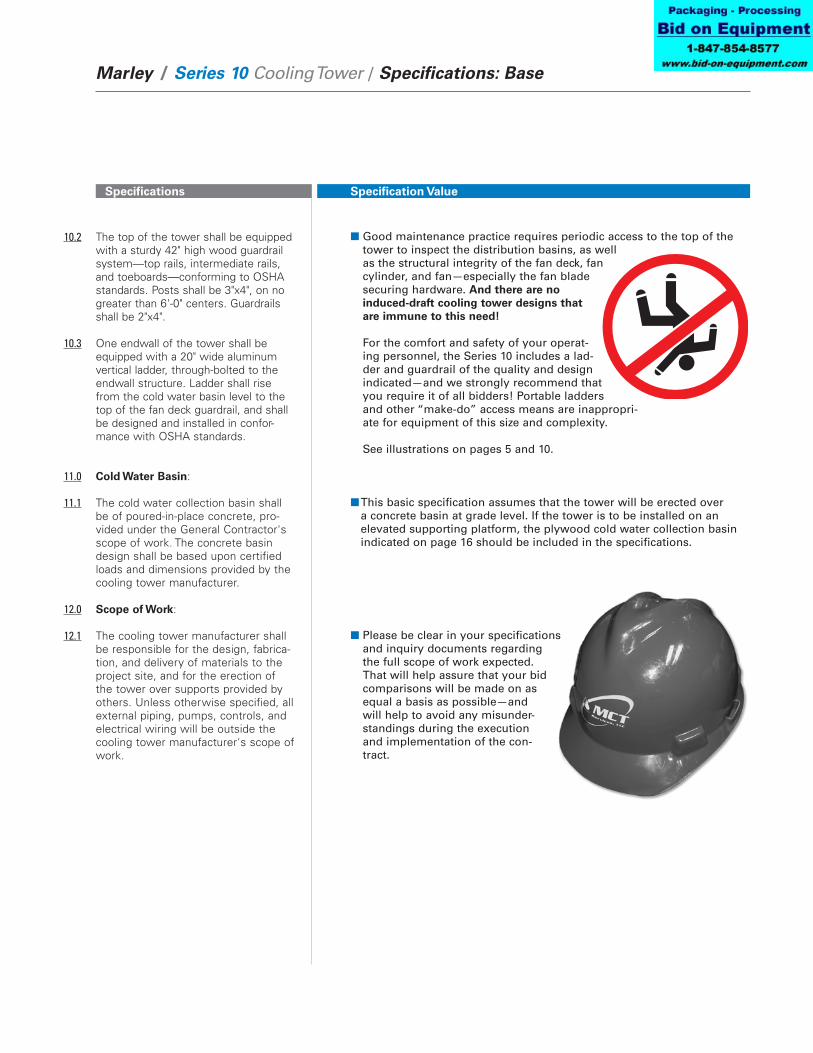
10.2 The top of the tower shall be equipped with a sturdy 42" high wood guardrail system—top rails, intermediate rails, and toeboards—conforming to OSHA standards. Posts shall be 3"x4", on no greater than 6'-0" centers. Guardrails shall be 2"x4".
10.3 One endwall of the tower shall be equipped with a 20" wide aluminum vertical ladder, through-bolted to the endwall structure. Ladder shall rise from the cold water basin level to the top of the fan deck guardrail, and shall be designed and installed in confor-mance with OSHA standards.
11.0 Cold Water Basin:
11.1 The cold water collection basin shall be of poured-in-place concrete, pro-vided under the General Contractor's scope of work. The concrete basin design shall be based upon certified loads and dimensions provided by the cooling tower manufacturer.
12.0 Scope of Work:
12.1 The cooling tower manufacturer shall be responsible for the design, fabrica-tion, and delivery of materials to the project site, and for the erection of the tower over supports provided by others. Unless otherwise specified, all external piping, pumps, controls, and electrical wiring will be outside the cooling tower manufacturer's scope of work.
■ Good maintenance practice requires periodic access to the top of the tower to inspect the distribution basins, as well as the structural integrity of the fan deck, fan cylinder, and fan—especially the fan blade securing hardware. And there are no induced-draft cooling tower designs that are immune to this need! For the comfort and safety of your operat-ing personnel, the Series 10 includes a lad-der and guardrail of the quality and design indicated—and we strongly recommend that you require it of all bidders! Portable ladders and other “make-do” access means are inappropri-ate for equipment of this size and complexity. See illustrations on pages 5 and 10.
■ This basic specification assumes that the tower will be erected over a concrete basin at grade level. If the tower is to be installed on an elevated supporting platform, the plywood cold water collection basin indicated on page 16 should be included in the specifications.
■ Please be clear in your specifications and inquiry documents regarding the full scope of work expected. That will help assure that your bid comparisons will be made on as equal a basis as possible—and will help to avoid any misunder-standings during the execution and implementation of the con-tract.

Specifications
Marley / Series 10 Cooling Tower / Specifications: Options 18
Specification Value
Control Options
Control System:
5.7: Add the following paragraph in the Mechanical Equipment sec-tion: Each cell of the cooling tower shall be equipped with a UL listed control system in a NEMA 3R or 4X outdoor enclosure capable of control-ling single-speed or two-speed motors as required, and designed specifi-cally for cooling tower applications. The panel shall include a main fused disconnect with an external operating handle, lockable in the off position for safety. Across-the-line magnetic start-ers or solid state soft-start starters as required shall be controlled with a thermostatic or solid state tempera-ture controller. Door mounted selector switches shall be provided to enable automatic or manual control and wired for 120VAC control. Control circuit to be wired out to terminal blocks for field connection to a remote vibration switch and for access to extra 120VAC 50VA control power, overload trip alarms and remote temperature control devices. The temperature controller shall be adjustable for the required cold water temperature. If a thermostatic controller is used it shall be mounted on the side of the tower with the tem-perature sensing bulb installed in the cold water basin using a suspension mounting bracket. If a solid state tem-perature controller is used the control-ler will be door mounted on the control panel. The temperature controller will display two temperatures, one for outgoing water and the other for set point. Water temperature input shall be obtained using a three-wire RTD with dry well in the outlet water piping and wired back to the solid state tempera-ture controller in the control panel.
■ If it is your opinion that the control system for the cooling tower should be part of the tower manufacturer’s responsibility, we are in whole-hearted agreement with you. Who better to determine the most efficient mode and manner of a tower’s operation—and to apply a system most compatible with it—than the designer and manufacturer of the cooling tower?

Specifications
Marley / Series 10 Cooling Tower / Specifications: Options 19
Specification Value
Basin Heaters:
11.2 Add the following paragraph in the Cold Water Basin section: Provide a system of electric immersion heat-ers and controls for each cell of the tower to prevent freezing of water in the collection basin during periods of shutdown. The system shall consist of one or more stainless steel electric immersion heaters installed in a galva-nized steel heat shield provided in the floor of the basin. A NEMA 4 enclosure shall house a magnetic contactor to energize heaters; a transformer to pro-vide 24 volt control circuit power; and a solid state circuit board for tempera-ture and low water cutoff. A control probe shall be located in the basin to monitor water level and temperature. The system shall be capable of main-taining 40°F water temperature at an ambient air temperature of ____ °F.
Variable Speed Drive:
5.7 Add the following paragraphs in the Mechanical Equipment Section: A complete UL listed Variable Speed Drive system in a NEMA 12 indoor or NEMA 3R outdoor enclosure shall be provided. The VFD shall use PWM tech-nology with IGBT switching and inte-grated by-pass design. The panel shall include a main disconnect with short circuit protection and external operat-ing handle, lockable in the off position for safety. The system shall include a solid state, PID temperature controller to adjust frequency output of the drive in response to the tower cold water temperature. The temperature of the cold water and set point shall be dis-played on the door of the control panel. The by-pass circuit shall include a com-plete magnetic bypass that isolates the VFD when in the bypass mode. Transfer to the bypass mode shall be automatic in the event of VFD failure or for trip faults. The bypass contactor shall be cycled on and off while operat-ing in bypass, to maintain the set-point temperature of the cold water. The drive design shall be operated as a stand- alone system or controlled with a building automation system.
■ The basin heater components described at left represent our recom-mendation for a reliable automatic system for the prevention of basin freezing. If aggressive operating conditions are anticipated, change “galvanized” in paragraph 11.2 to “Series 300 SS”. The ambient air temperature that you fill in should be the lowest 1% level of winter temperature prevalent at site. Ask for Marley drawing 92-3627.
■ Marley VFD drive systems are designed to combine absolute tempera-ture control with ideal energy management. The cooling tower user selects a cold water temperature and the drive system will vary the fan speed to maintain that temperature. Precise temperature control is accomplished with far less stress to the mechanical equipment com-ponents. The improved energy management provides fast payback. Indeed, many utilities offer generous rebates for users having installed VFD drives.
➠

Specifications
Marley / Series 10 Cooling Tower / Specifications: Options 20
Specification Value
The BAS can be the normal source of control and the integrated temperature controller may be used as a backup to the building automation system.
Operator controls shall be mounted on the front of the enclosure and shall consist of start and stop control, bypass/VFD selec-tor switch, Auto/Manual selector switch, manual speed control, and solid state temperature controller. An emergency bypass selector switch internal to the panel allowing the cooling tower fan motor to be run at full speed shall be furnished.
To prevent heating problems in the cool-ing tower fan motor and to assure proper gear reducer lubrication the VFD system shall cycle the motor on/off when the mini-mum allowable motor speed is reached.
The cooling tower manufacturer shall supply VFD start-up and tower vibra-tion testing to identify and lock out any vibration levels which may exceed CTI guidelines.
Vibration Limit Switch:
5.8 Add the following paragraph in the Mechanical Equipment section: A single-pole, double-throw vibration limit switch in a NEMA 4 housing shall be installed on the mechanical equipment support for wiring into the owner’s control panel. The purpose of this switch will be to interrupt power to the motor in the event of excessive vibra-tion. It shall be adjustable for sensitiv-ity, and shall require manual reset.
■ Unless specified otherwise, a Metrix switch will be provided. A double-pole, double-throw model is also available. If purchased in con-junction with the Control System, it is also factory-wired. The requirement for manual reset assures that the tower will be visited to determine the cause of excess vibration.
Specifications
Marley / Series 10 Cooling Tower / Specifications: Options 21
Specification Value
Convenience and Safety Options
Stairway:
10.3 Replace this paragraph with the fol-lowing: A 30" wide, column supported, 45° stairway with 8" rise and run, of treated Douglas Fir shall be provided at the tower endwall rising from grade (roof) to the fan deck elevation. Stair columns shall be 3"x4". Guardrails shall be 2"x4". The upper guardrail shall have an eased edge for the protection of operating personnel. Stairway founda-tion shall be by others, designed in accordance with drawings provided by the cooling tower manufacturer. The stairway shall conform to OSHA stan-dards.
Plenum Walkway:
10.1 Add the following to the end of this paragraph: Provide a 24" wide walkway extending from one endwall access door to the other through the length of the tower. Walkway shall be constructed of treated Douglas Fir, and the top of the walkway shall be above the cold water basin overflow level. If the cold water basin is deeper than 4'-0", the walkway shall be equipped with guardrails.
Ladder Extension:
10.4 Add the following paragraph in the Access and Safety section: Provide a ladder extension for connection to the foot of the ladder attached to the tower casing. This extension shall be long enough to rise from the roof (grade) level to the base of the tower. Anchorage and lateral bracing of the ladder extension shall be by others.
■ Although they are not necessary for routine operation and mainte-nance, stairways do provide a safe and comfortable means of access to the top of the tower that is often overlooked in the initial cooling tower purchase.
■ This option permits freedom of movement for inspection or mainte-nance within the tower without the need for wading boots or tower drainage. It also helps prevent maintenance personnel from damag-ing submerged accessories in the cold water basin (such as screens, probes, basin heaters, etc.).
■ Many towers are installed such that the base of the tower is 2'−0" or more above the roof or grade level. This makes it difficult to get up to the foot of the attached ladder. The ladder extension alleviates this problem. Marley ladder extensions are available in standard 5'−0" and 11'−0" lengths, and will be field-cut to fit.

Specifications
Marley / Series 10 Cooling Tower / Specifications: Options 22
Specification Value
Ladder Safety Cage:
10.3 Add the following to the end of this paragraph: A heavy gauge galvanized steel safety cage shall surround the ladder, extending from a point approxi-mately 7'-0" above the foot of the ladder to the top of the guardrail sur-rounding the fan deck.
Oil Level Sight Glass:
5.4 Replace paragraph 5.4 with the fol-lowing: A galvanized oil gauge and drain line shall extend from the gear reducer to the vicinity of the motor, and shall be equipped with a bronze-bodied oil level sight glass.
Miscellaneous Options
Wood Cold Water Basin:
11.1 Replace this paragraph with the fol-lowing: Include a cold water collection basin constructed of pressure treated Douglas Fir plywood. Basin floor shall be 3⁄4" thick, 5-ply, supported by 6" deep joists on 2'-0" centers. Basin sides shall be 1" thick, 7 ply. The basin floor shall lock into a dado groove in the basin sides to form a watertight seal. A depressed, side outlet sump of hot-dip galvanized steel having a 1⁄4" thick faceplate drilled for a standard class 125 ASME flange connection will be included. An appropriately sized (3" diameter or larger) galvanized stand-pipe overflow shall be provided. The standpipe shall be removable for flush-out cleaning of the basin. A float-oper-ated, mechanical makeup valve shall also be included, installed adjacent to the endwall access door.
■ To meet OSHA guidelines, towers whose fan decks are 20'-0" or more above roof or grade, and which are equipped with ladders, are required to have safety cages surrounding the ladders.
■ The oil level sight glass is a convenience item that is preferred by many users. The same pur-pose is, of course, served by either the dip stick or the sight glass. If aggressive operating conditions are anticipated, change “galvanized” in paragraph 5.4 to “Series 300 SS”.
■ Marley basins are used to permit the installation of towers on elevated platforms or foundations. The cross section illustration on page 4 shows the relationship of the optional basin, sump and overflow to a typical steel I-beam support platform. See illustrations on pages 5 and 10.

Specifications
Marley / Series 10 Cooling Tower / Specifications: Options 23
Specification Value
PVC Fill Splash Bars:
6.1 Change 2nd sentence to read as follows: Splash bars shall be hollow, extruded, structural bars of PVC, a minimum of 3⁄4" thick x 1-5⁄8" wide x 4'-0" long.
Redwood Components:
Hot Water Basin Covers: 8.3 Add the following paragraph in
the Hot Water Distribution System section: The distribution basins shall include treated Douglas Fir plywood covers at least 3⁄4" thick. These covers shall be designed to withstand 40 psf live load, and shall be easily removable for maintenance.
Air Inlet Screens:
9.3 Add the following paragraph in the Casing and Louvers section: The air inlet faces of the tower shall be covered by 1" mesh hot-dip galvanized welded wire screens. Screens shall be secured to removable treated Douglas Fir frames.
Watertight Partitions Between Cells: 3.5 Replace the last sentence in this
paragraph with the following: Partitions shall be 3⁄4" x 5-ply, factory-fabricated, grooved and splined, treat-ed Douglas Fir plywood sheets; and shall be full height, full width of the tower, installed and sealed watertight to permit separate cell operation.
■ Extruded PVC has a smooth, nonporous surface which naturally resists the adherence of slime, algae, biological growth, and turbidity. It also, of course, has a much better fire rating than does wood. PVC splash bars can produce a different level of thermal performance than wood. Make sure that the model you have selected takes this into account.
■ Most of the wood components in the tower are available in pressure treated redwood. However, redwood lacks the strength of Douglas Fir, which may require structural modifications of the tower. Please discuss the available redwood options with your local Marley representative.
■ These covers are designed to keep leaves and debris out of the circulating water system. They also serve to suppress algae formation by shielding the incoming hot water from direct sunlight.
■ In wooded or windy areas, these screens help to keep leaves or blowing debris out of the cool-ing tower and circulating water system.
■ In addition to the normal partition function of preventing air bypass (page 12), this option allows you to use each partitioned cell of your tower independently. This is valuable where a single multicell tower is serving several separate systems—or where winter operation may require less than full tower capability.

Specifications
Marley / Series 10 Cooling Tower / Specifications: Options 24
Specification Value
FRP Louvers:
9.2 Replace this paragraph with the follow-ing: The air intake faces of the tower shall be louvered full length, full height. Louvers shall be corrugated FRP, supported on no more than 4'-0" centers. They shall be slip-fit into deep routed slots in the louver columns. Louvers shall be sloped to shed water inward to the tower, and shall be “sight-tight” at horizontal view.
Low Noise Tower:
1.1 Add the following at the end of this paragraph: The cooling tower shall be quiet operating, and shall produce an overall level of sound no higher than ____ dBA at the critical location indicated on the Plans.
■ This option is not recommended in those northern regions where heavy ice and snow loads can occur.
■ Sound produced by a Series 10 tower operating in an unobstructed
environment will meet all but the most restrictive noise limitations—and will react favorably to natural attenuation. Where the tower has been sized to operate within an enclosure, the enclosure itself will have a damping effect on sound. Sound also declines with distance—by about 5 or 6 dBA each time the distance doubles. Where noise at a critical point is likely to exceed an acceptable limit, you have several options—listed below in ascending order of cost impact: • Where only a slight reduction in noise will satisfy — and the source
of concern is in a particular direction — merely turning the tower may be the answer. Less sound emanates from the cased face of the tower than does from the air intake face.
• In many cases, noise concerns are limited to nighttime, when ambi-ent noise levels are lower and neighbors are trying to sleep. You can usually resolve these situations by using two-speed motors in either 1800/900 or 1800/1200 RPM configuration; and operating the fans at reduced speed without cycling “after hours”. (The natural nighttime reduction in wet-bulb temperature makes this a very feasible solution in most areas of the world, but the need to avoid cycling may cause the cold water temperature to vary significantly.)
• Variable speed drives automatically minimize the tower's noise level during periods of reduced load and/or reduced ambient without sacri-ficing the system's ability to maintain a constant cold water tempera-ture. This is a relatively inexpensive solution, and can pay for itself quickly in reduced energy costs.
• Where noise is a concern at all times (for example, near a hospital), the best solution is to oversize the tower so it can operate continu-ously at reduced (1200 or 900 RPM) motor speed even at the highest design wet-bulb temperature. Typical sound reductions are 7 dBA at 2⁄3 fan speed or 10 dBA at 1⁄2 fan speed, but larger reductions are often possible.
• Extreme cases may require inlet and discharge sound attenuator sections; however, the static pressure loss imposed by attenuators may necessitate an increase in tower size. This is the least desirable approach because of the significant cost impact – and because of the obstruction to normal maintenance procedures.
Your Marley representative can help you meet your sound require-ments.

Specifications
Marley / Series 10 Cooling Tower / Specifications: Options 25
Specification Value
■ Occasionally, critical processes or local codes may require you to install a fire-protection sprinkler system on a wood tower—or pay higher insurance premiums—or both. An alternative that could be acceptable to your insurance carrier, and which you may wish to evaluate, would be to make your Series 10 tower as fire resistant as possible. This can be done by any or all of the following mea-sures: • FRP casing having a flame spread rating of 25 or less. (Para. 9.1)
• Fan cylinders of fire-retardant FRP having a flame spread rating of 25 or less. (Para. 4.2)
• 1⁄4" thick fireproof fiber reinforced cement overlay over the fan deck—and FRC overlayed distribution basin covers. (Para. 4.1 & page 23)
• 3⁄4" thick plywood partitions both sides of the column line between cells to achieve a fire rating of at least 30 minutes. (Para. 3.5. & page 23)
• PVC fill splash bars as described on Page 22.
Fire Safety Options: