markus tessmann, innogames
TRANSCRIPT

MESH MODIFICATION:CPU VS GPU
Markus Tessmann
Technical Artist, InnoGames

ABOUT ME
• Founded Vancouver, Canada’s first 3D CG company in in 1986
• Focused on film and TV
• Created artwork and developed tools
• Entered the game industry in 1992
• Lead Artist at Electronic Arts, Disney
• Independent developer (for clients including Sega, Fox)
• Developed for consoles, PC and mobile platforms
• Moved to Germany in 2014
• Now, a Technical Artist at InnoGames

WHY MODIFY MESHES AT RUNTIME?
• Some things can’t be modelled/animated beforehand in a 3D tool

WHY MODIFY MESHES AT RUNTIME?
• Some things can’t be modelled/animated beforehand in a 3D tool
• Localized mesh influence (like damage)
• World position based effects (wind)
• Effects with a random nature
• Effects on hiddenmeshes (sprites)
• Effects requiring generation of data (UVs, normals)

PROCESSING POWER
• Two different paths available for processing mesh data

PROCESSING POWER
Central Processor (CPU) Graphics Processor (GPU)

PROCESSING POWER
Central Processor (CPU)
• General purpose
Graphics Processor (GPU)

PROCESSING POWER
Central Processor (CPU)
• General purpose
Graphics Processor (GPU)
• Highly specialized

PROCESSING POWER
Central Processor (CPU)
• General purpose
• Two to eight cores
Graphics Processor (GPU)
• Highly specialized

PROCESSING POWER
Central Processor (CPU)
• General purpose
• Two to eight cores
Graphics Processor (GPU)
• Highly specialized
• Up to thousands of cores!

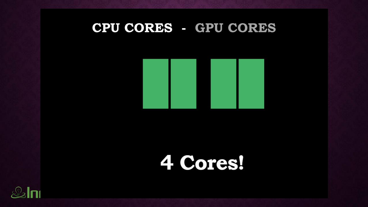
CPU CORES - GPU CORES
CPU CORES - GPU CORES

CPU CORES - GPU CORES

CPU CORES - GPU CORES

CPU CORES - GPU CORES

PROCESSING POWER
Central Processor (CPU)
• General purpose
• Two to eight cores
Graphics Processor (GPU)
• Highly specialized
• Up to thousands of cores!
• hardware processing of vertex data

PROCESSING POWER
Central Processor (CPU)
• General purpose
• Two to eight cores
• Access via Unity C# scripts in
these examples
Graphics Processor (GPU)
• Highly specialized
• Up to thousands of cores!
• hardware processing of vertex data
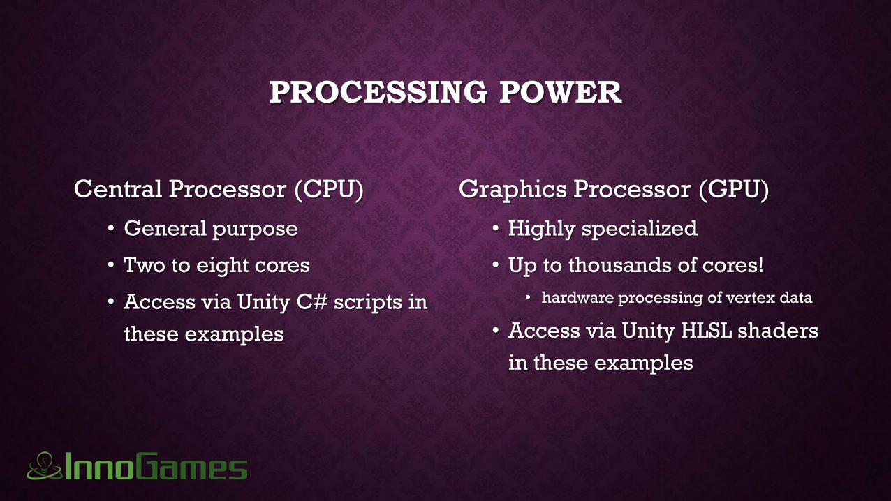
PROCESSING POWER
Central Processor (CPU)
• General purpose
• Two to eight cores
• Access via Unity C# scripts in
these examples
Graphics Processor (GPU)
• Highly specialized
• Up to thousands of cores!
• hardware processing of vertex data
• Access via Unity HLSL shaders
in these examples

THE GPU PIPELINE

THE GPU PIPELINE

THE GPU PIPELINE
• Application vertex has position, color, normal, texture coordinates
• Transformed data is triangles assembled from multiple vertices which gets rasterized
• Fragments from interpolated vertices are processed and blended into final pixels

THE GPU PIPELINE
• Application vertex has position, color, normal, texture coordinates
• Transformed data is triangles assembled from multiple vertices which gets rasterized
• Fragments from interpolated vertices are processed and blended into final pixels

WHAT’S IN A MESH?

WHAT’S IN A MESH?
Vertex Data
• 3D points in space
• Stored in a list/array and accessed
by index number

WHAT’S IN A MESH?
Triangle Data
• References vertex points as
indices
• Triangles, because they’re always
planar

WHAT’S IN A MESH?
Triangle Data
• References vertex points as
indices
• Triangles, because they’re always
planar
• Surface visibility determined by
clockwise order of vertices
• Shared vertices and edges
important for smoothing

WHAT’S IN A MESH?
UV Data
• Vertices in 2D that associate with
3D vertices to establish connection
to 2D data
• Used for texture maps, normal
maps, bump maps, …
• Geometry may have multiple UV
arrays per mesh

WHAT’S IN A MESH?
Normal Data
• Normals are vectors used by
lighting calculations to determine
surface brightness
• Vertex normals are stored with
mesh in an array/list.
• Surface normals stored separately
as image files.

WHAT’S IN A MESH?
Colour Data
• An RGBA colour value is stored
with each vertex.
• May be used for colour, but
typically used as reference
information for shaders
• Usually created in 3D modelling
software but often calculated
• Essentially, 4 floats available for…

DATA STRUCTURES
Unity C# (CPU) Unity Shader (GPU)

DATA STRUCTURES
Unity C# (CPU)
• Mesh instance to get access to data
Unity Shader (GPU)
• Vertex data sent from application (a2v)

DATA STRUCTURES
Unity C# (CPU)
• Mesh instance to get access to data
• Data stored in arrays
Unity Shader (GPU)
• Vertex data sent from application (a2v)
• Data stored in registers for IN and OUT

DATA STRUCTURES
Unity C# (CPU)
• Mesh instance to get access to data
• Data stored in arrays
• vector3[ ] for vertices
Unity Shader (GPU)
• Vertex data sent from application (a2v)
• Data stored in registers for IN and OUT
• float4 POSITION for vertex
DATA STRUCTURES
Unity C# (CPU)
• Mesh instance to get access to data
• Data stored in arrays
• vector3[ ] for vertices
• int[ ] for triangles
Unity Shader (GPU)
• Vertex data sent from application (a2v)
• Data stored in registers for IN and OUT
• float4 POSITION for vertex
• Vertex Buffers – outside the scope of this talk!

DATA STRUCTURES
Unity C# (CPU)
• Mesh instance to get access to data
• Data stored in arrays
• vector3[ ] for vertices
• int[ ] for triangles
• Vector2[ ] for UVs
Unity Shader (GPU)
• Vertex data sent from application (a2v)
• Data stored in registers for IN and OUT
• float4 POSITION for vertex
• Vertex Buffers – outside the scope of this talk!
• fixed4 TEXCOORD0 for UVs (also 1, 2…7)

DATA STRUCTURES
Unity C# (CPU)
• Mesh instance to get access to data
• Data stored in arrays
• vector3[ ] for vertices
• int[ ] for triangles
• Vector2[ ] for UVs
• Vector3[ ] for normals
Unity Shader (GPU)
• Vertex data sent from application (a2v)
• Data stored in registers for IN and OUT
• float4 POSITION for vertex
• Vertex Buffers – outside the scope of this talk!
• fixed4 TEXCOORD0 for UVs (also 1, 2…7)
• fixed4 NORMAL for normals

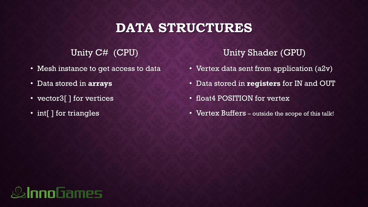
DATA STRUCTURES
Unity C# (CPU)
• Mesh instance to get access to data
• Data stored in arrays
• vector3[ ] for vertices
• int[ ] for triangles
• Vector2[ ] for UVs
• Vector3[ ] for normals
• Vector4[ ] for colours
Unity Shader (GPU)
• Vertex data sent from application (a2v)
• Data stored in registers for IN and OUT
• float4 POSITION for vertex
• Vertex Buffers – outside the scope of this talk!
• fixed4 TEXCOORD0 for UVs (also 1, 2…7)
• fixed4 NORMAL for normals
• fixed4 COLOR0 for colour

STEPS IN UNITY FOR MODIFYING A MESH

STEPS IN UNITY FOR MODIFYING A MESH// get an instant of the mesh to modify
Mesh theMesh = GetComponent<MeshFilter>().mesh;

STEPS IN UNITY FOR MODIFYING A MESH// get an instant of the mesh to modify
Mesh theMesh = GetComponent<MeshFilter>().mesh;
// copy the vertices, normals, uvs, colors
Vector3[] theVertices = theMesh.vertices;
Vector2[] theUVs = theMesh.uv;
Vector3[] theNormals = theMesh.normals;
Vector4[] theColors = theMesh.colors;
// perform any manipulations
for (int i = 0; i < theVertices.Length; i++)
{
theVertices[i] += theNormals[i] * Random.Range(0f,1f);
theUVs[i] = new Vector2(theUVs[i].y, theUVs[i].x);
}
// assign the vertices back to the mesh
theMesh.uv = theUVs;
theMesh.vertices = theVertices;
theMesh.RecalculateNormals();

STEPS IN SHADER FOR MODIFYING A MESH

STEPS IN SHADER FOR MODIFYING A MESH// define registers to use application mesh data
struct a2v
{
float4 vertex : POSITION;
fixed3 normal : NORMAL;
fixed2 uv : TEXCOORD0;
fixed2 color : COLOR1;
};

STEPS IN SHADER FOR MODIFYING A MESH// define registers to use application mesh data
struct a2v
{
float4 vertex : POSITION;
fixed3 normal : NORMAL;
fixed2 uv : TEXCOORD0;
fixed2 color : COLOR1;
};
// define registers for passing data to fragment processor
struct v2f
{
float4 pos : POSITION;
fixed2 uv : TEXCOORD0;
};

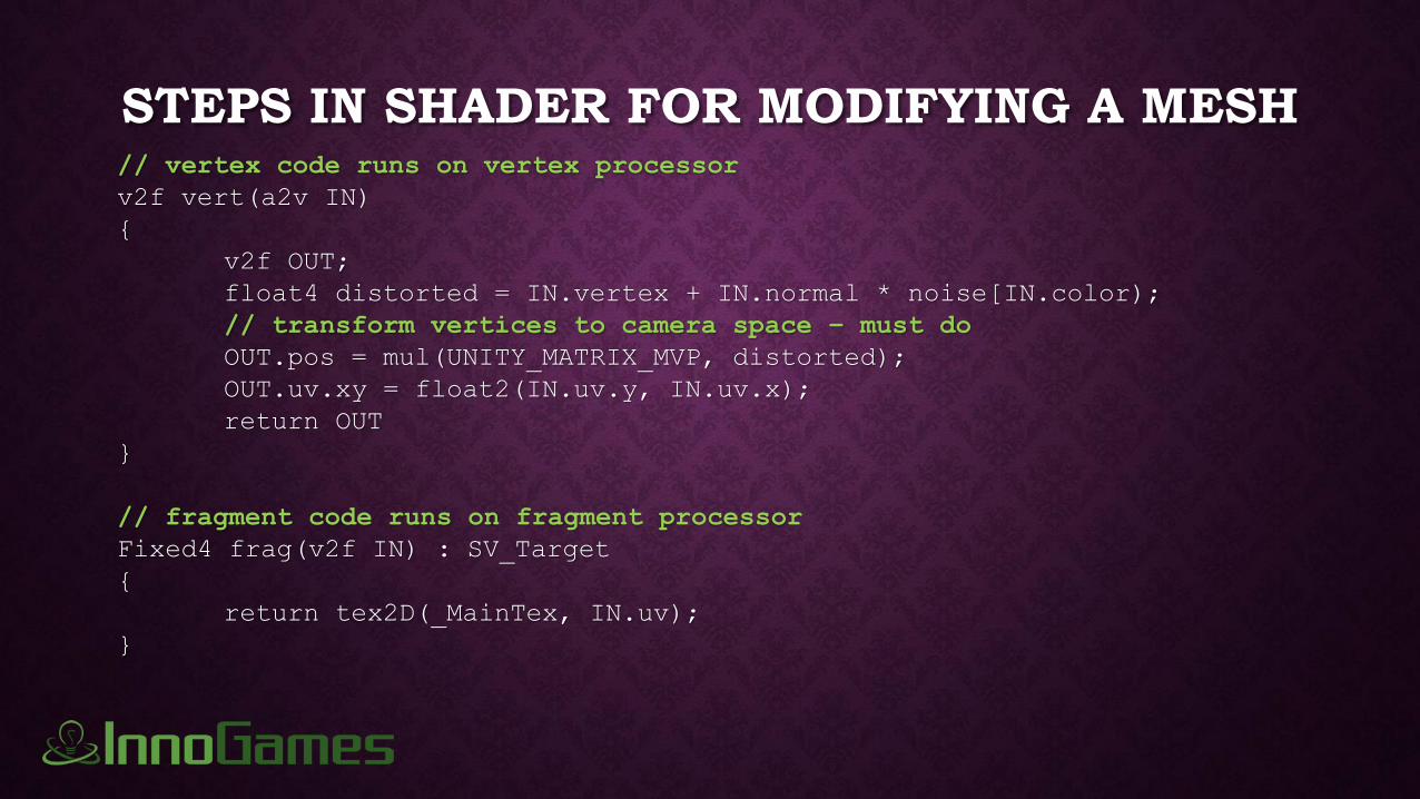
STEPS IN SHADER FOR MODIFYING A MESH// vertex code runs on vertex processor
v2f vert(a2v IN)
{
v2f OUT;
float4 distorted = IN.vertex + IN.normal * noise[IN.color);
// transform vertices to camera space – must do
OUT.pos = mul(UNITY_MATRIX_MVP, distorted);
OUT.uv.xy = float2(IN.uv.y, IN.uv.x);
return OUT
}
// fragment code runs on fragment processor
Fixed4 frag(v2f IN) : SV_Target
{
return tex2D(_MainTex, IN.uv);
}

SIMPLE SINE SURFACE
This simple example will use a math function to deform a grid…

SIMPLE SINE SURFACE

SINE SURFACE IN UNITY C#using UnityEngine;
using System.Collections;
public class SineSurface : MonoBehaviour {
public float Speed = 5f;
public float Height = 1f;
public float Size = .1f;
public bool UseWorldCenter;
void Update () {
SineWave();
}
private void SineWave()
{
Mesh mesh = GetComponent<MeshFilter>().mesh;
Vector3[] vertices = mesh.vertices;
float radius;
int i = 0;

SINE SURFACE IN UNITY C#while (i < vertices.Length) {
if (UseWorldCenter)
{
Vector3 worldPt = transform.TransformPoint( vertices[i] );
radius = Vector2.Distance( new Vector2( worldPt.x, worldPt.z ), Vector2.zero ) * Size;
} else
{
radius = Vector2.Distance( new Vector2( vertices[i].x, vertices[i].z ), Vector2.zero ) * Size;
}
float vertexY = Mathf.Sin( radius - Time.time * Speed ) * Height;
vertices[i] = new Vector3( vertices[i].x, vertexY, vertices[i].z );
i++;
}
mesh.vertices = vertices;
mesh.RecalculateNormals( );
}

SINE SURFACE IN UNITY SHADERShader "MT/SineSurface“
{
Properties {
_MainTex ("Texture", 2D) = "white" {}
_Speed("Speed", float) = 1
_Height("Height", float) = 0.1
_Size("Size", float) = 1
_BlendMe("Blend between effect centers", Range(0,1)) = 0
}
SubShader {
Tags { "Queue"="Geometry"}
Pass {
CGPROGRAM
#pragma vertex vert
#pragma fragment frag
sampler2D _MainTex;
float _Speed;
float _Height;
float _Size;
float _BlendMe;

SINE SURFACE IN UNITY SHADER
struct a2v
{
float4 vertex : POSITION;
fixed4 uv : TEXCOORD0;
};
struct v2f
{
float4 pos : SV_POSITION;
fixed4 uv : TEXCOORD0;
};

SINE SURFACE IN UNITY SHADERv2f vert (a2v IN)
{
v2f OUT;
// calculate the effect in world space
float4 worldPt = mul( unity_ObjectToWorld, IN.vertex );
radius = distance( float2( worldPt.x, worldPt.z), float2( 0, 0 )) * _Size;
float vertexWorldY = sin( radius - _Time.y * _Speed ) * _Height;
// calculate the effect in local object space
float radius = distance(float2( IN.vertex.x, IN.vertex.z), float2( 0, 0 )) * _Size;
float vertexObjectY = sin( radius - _Time.y * _Speed ) * _Height;
// blend between the two
float nowVertexY = lerp(vertexObjectY, vertexWorldY, _BlendMe);
OUT.pos = mul( UNITY_MATRIX_MVP, float4( IN.vertex.x, nowVertexY, IN.vertex.z, IN.vertex.w ));
OUT.uv = IN.uv;
return OUT;
}

SINE SURFACE IN UNITY SHADER
fixed4 frag (v2f IN) : SV_Target
{
return tex2D(_MainTex, IN.uv);
}
ENDCG
}
}
}

CHOOSING CPU OR GPU
We will look at three case studies:

CHOOSING CPU OR GPU
We will look at three case studies:
1. Tank Tread
• Equal case for CPU or GPU

CHOOSING CPU OR GPU
We will look at three case studies:
1. Tank Tread
• Equal case for CPU or GPU
2. Underwater Refraction
• Strong case for using the GPU

CHOOSING CPU OR GPU
We will look at three case studies:
1. Tank Tread
• Equal case for CPU or GPU
2. Underwater Refraction
• Strong case for using the GPU
3. Bombed Terrain
• Strong case for using CPU

CASE STUDY #1 – TANK TREAD
• Moving tread is really complex to animate with a 3D app!
• Animating UV data is the solution
• So, CPU or GPU?
• If the tread was constantly (or usually) turning, GPU might be better
• If the tread stops a lot or requires separate tread control (robot turning), CPU might be
better
• We will look at both implementations anyway
• C# script to animate UV data via the CPU
• Shader to animate UV data via the GPU

ROBOT TREAD

ROBOT TREAD ELEMENTS

Red vertex colours used to
identify affected region
Affected texture region
isolated from other texture
components

ROBOT TREAD IN UNITY C#
void MoveRedUVs()
{
Mesh theMesh = GetComponent<MeshFilter>().mesh;
Vector2[] theUVs = theMesh.uv;
Color[] theColors = theMesh.colors;
for (int i = 0; i < theUVs.Length; i++)
{
float offset = TreadSpeed * Time.deltaTime
float newV = theUVs[i].y + ( theColors[i].r * offset );
theUVs[i] = new Vector2( theUVs[i].x, newV );
}
theMesh.uv = theUVs;
mesh.RecalculateNormals();
}

ROBOT TREAD IN UNITY SHADERstruct a2v {
float4 vertex : POSITION;
fixed4 uv : TEXCOORD0;
fixed4 color : COLOR0;
};
struct v2f {
float4 pos : SV_POSITION;
fixed4 uv : TEXCOORD0;
};
v2f vert (a2v IN)
{
v2f OUT;
OUT.pos = mul(UNITY_MATRIX_MVP, IN.vertex);
float offset = _MainTex_ST.x * _Time.y;
float newV = IN.uv.y + ( IN.color.r * offset );
OUT.uv = fixed4( IN.uv.x, newV, 0, 1 );
return OUT;
}

ROBOT TREAD IN UNITY’S INSPECTOR
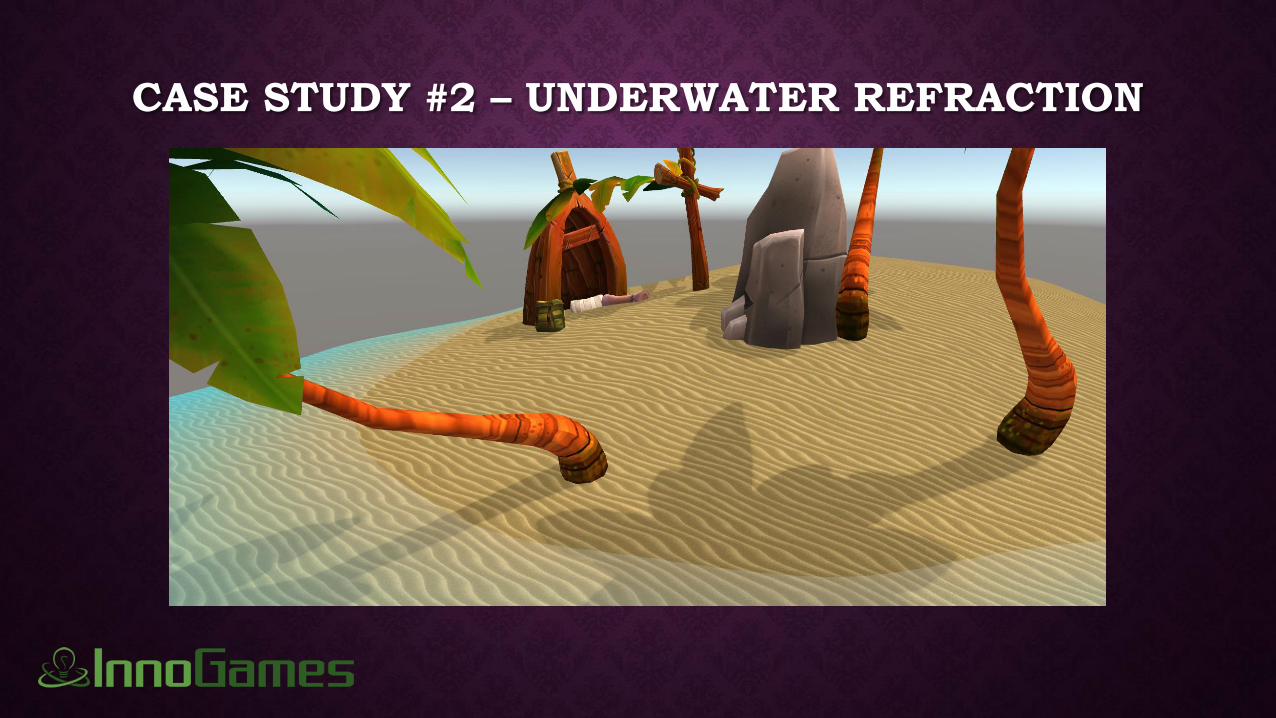
CASE STUDY #2 – UNDERWATER REFRACTION

CASE STUDY #2 – UNDERWATER REFRACTION
• Can’t be animated with 3D app as the effect depends on position
• Using C#, every object to be animated would need the script
• not practical
• Using HLSL, every object needs to have the same shader or similar function available
to multiple shaders
• very typical (and preferred) that multiple objects share material/shader
• We will look at the shader implementation
• Shader animates mesh data
• Shader already used to influences texture colour

REFRACTION EFFECT IN UNITY SHADERv2f vert (a2v IN)
{
v2f OUT;
OUT.pos = mul( UNITY_MATRIX_MVP, IN.vertex );
OUT.uv = IN.uv;
half depth = abs( min ( 0, mul( _Object2World, IN.vertex ).y ) );
OUT.uv.z = depth;
half offset = sin( IN.vertex.y * _WiggleFrequency + _Time.w * _WiggleSpeed ) * _WiggleMagnitude * depth;
OUT.pos.x += min( _Range, max( -_Range, offset ) );
OUT.color = VertexLighting(IN.vertex, IN.normal, 4);
TRANSFER_VERTEX_TO_FRAGMENT(OUT);
return OUT;
}
fixed4 frag ( v2f IN ) : SV_Target
{
fixed4 col = tex2D( _MainTex, IN.uv ) * IN.color;
return lerp( col, _SeaColour, min( IN.uv.z, .7 ) );
}

CASE STUDY #3 – BOMBED TERRAIN

CASE STUDY #3 – BOMBED TERRAIN

CASE STUDY #3 – BOMBED TERRAIN
• Can’t be modelled in advance because unknown where bomb will land
• Effect should be persistent, so CPU is the best choice because the mesh won’t need
to be affected every frame.
• Not a trivial problem anyway because Unity maintains no shared vertex information
• This solution scans the entire mesh to see what vertices are influenced by bomb
• New UV set is created to show bombed area with separate texture image
• GPU version would be very complicated, so I haven’t tried that for this.
• Likely involving updating an image at runtime to control offset of bombed area.
• Try it in a browser at www.rockfarm.ca

CONCLUSION: CPU OR GPU
Likely best for CPU Likely best for GPU

CONCLUSION: CPU OR GPU
Likely best for CPU
• intermittently occurring effects
• effects requiring user/game input
• persistent changes to mesh
• C# easier to write, better editor support
Likely best for GPU
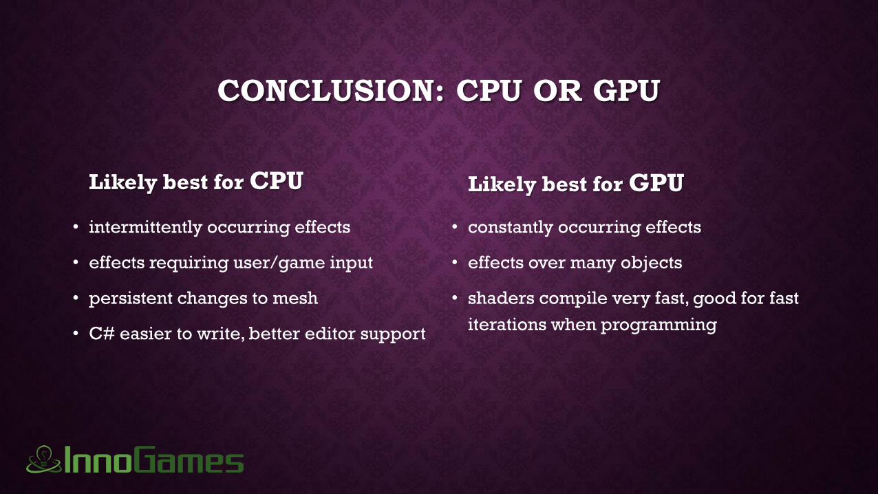
CONCLUSION: CPU OR GPU
Likely best for CPU
• intermittently occurring effects
• effects requiring user/game input
• persistent changes to mesh
• C# easier to write, better editor support
Likely best for GPU
• constantly occurring effects
• effects over many objects
• shaders compile very fast, good for fast
iterations when programming

Questions?
(we’re hiring!)
www.rockfarm.ca