mark david muller, cpo, ms, faaopsocket also should provide adequate sta-bility in the sagittal,...
TRANSCRIPT

AbstractClinicians have long strived to create optimal transfemoral prosthetic designs that will not only enhance the user’s ability to ambulate but also will be a functional element of the individual’s life. Although there have been many advancements in materials, socket designs, and components, there has been little research to help quantify how the individuals that use these prosthetics devices can best be served. It is helpful to explore clinical considerations and anticipated outcomes when creating transfemoral prosthetic devices. Prosthesis use is aff ected by many factors, including energy expenditure, body image, voluntary control within a transfemoral prosthetic system, socket fi t and design, component selection, and alignment.
537 © 2016 American Academy of Orthopaedic Surgeons Atlas of Amputations and Limb Defi ciencies, Fourth Edition
Chapter 46
Keywords: prosthetics; transfemoral alignment; transfemoral prosthetic socket; transfemoral prosthetic suspension
IntroductionAmputations at the transfemoral level account for approximately 19% of the approximately 1.6 million individuals in the United States who are currently living with an amputation.1-3 Statistics from 2004 reported that 31% of all ma-jor amputations were performed at the transfemoral level,4,5 with new evidence showing a decrease in the number of transfemoral amputations performed each year.2 There also is evidence that individuals who have undergone am-putation are living longer and will re-quire prosthetics services throughout their lives.1,6 In 2014, certifi ed prosthetic practitioners spent more than 25% of their time caring for patients with a transfemoral amputation.7
Those in the fi eld of prosthetics have a long history of involvement with transfemoral prosthetic socket design and construction, with the fi rst patents awarded in England in 1790 and the fi rst US patent for a transfemoral arti-fi cial limb given in 1846.8-12 However, prosthetists still do not have universal
clinical standards of practice for device creation, fi t, suspension, and alignment. Throughout history, transfemoral design and fabrication techniques have been passed down from mentors to protégés, with no formal instructional cours-es available in the United States until 1949 when the University of California at Berkeley introduced a short course in transfemoral design of a suction sock-et. In the 1950s, several universities began formal education programs in prosthetics, with each school creating their own laboratory manuals and de-sign iterations.13 The prevalent design at that time was the German transfemoral quadrilateral socket, which used skin suction suspension.14,15 In the 1980s, the fi rst ischial containment manual emerged and was quickly adapted by other institutions, although each insti-tution implemented design iterations. As of 2014, there were 11 accredited institu-tions offering master level education for prosthetic and orthotic practitioners in the United States, with each institution offering differing theories and practical
implementation techniques for trans-femoral socket design, suspension, and clinical application.
One rationale for the differing de-signs may be the variability observed in the anatomy, size, and length of trans-femoral residual limbs, as well as the level of voluntary control the individual possesses. It is accepted that no single design is appropriate for every individ-ual with a transfemoral amputation. Accordingly, variations in the clinical applications of formalized training have led numerous practitioners to create unique styles and techniques.9,10,16,17
These variations provide practitioners with the ability to adapt a transfemoral socket to best meet the needs and goals of an individual patient.
The common clinical goals and con-siderations that guide rehabilitation professionals through this patient-spe-cifi c process are discussed in this chap-ter along with an overview of current transfemoral socket designs and the implications of suspension, alignment, and biomechanical considerations in evaluating, fabricating, and fi tting trans-femoral prostheses.
Clinical Considerations and Anticipated OutcomesAlthough prosthetic devices will never truly replace a missing limb, certain clinical considerations must be ad-dressed, irrespective of which socket or suspension design is chosen. The trans-femoral prosthetic system must balance function, comfort, and appearance both dynamically and statically.8,11,12 To create the most appropriate plan, the treating team must consider energy ex-penditure, body image, the user’s level
Transfemoral Amputation: Prosthetic ManagementMark David Muller, CPO, MS, FAAOP
Mr. Muller is the owner of K&M Clinical Services LLC.

Atlas of Amputations and Limb Defi ciencies, Fourth Edition © 2016 American Academy of Orthopaedic Surgeons 538
of voluntary control, and the fi t of the prosthetic socket. In implementing the treatment plan, the team must deter-mine socket construction and design, the degree and complexity of the sus-pension system, the appropriate com-ponents, alignment considerations, and outcome measures.
Energy ExpenditureEnergy expenditure for a transfemoral amputee is of great concern. The effort required to ambulate with a prosthetic device at this level is dependent on the weight of the device, the quality of fi t, the degree of suspension, the accuracy of alignment, and functional character-istics of the chosen components.17-21 If any one of these factors is not prop-erly addressed, the individual using a transfemoral prosthesis will exhibit higher levels of energy expenditure during ambulation than are neces-sary. Increased energy expenditure is accompanied by an increase in the rate of oxygen consumption and an associ-ated elevation in heart rate. An elevated heart rate can, in turn, lower the user’s self-selected walking speed and reduce gait effi ciency.22 For elderly individ-uals with a transfemoral prosthesis, the physical burden of ambulating with a prosthetic device may exceed their abilities, leading to a lower rate of prosthetic use.20,23 Knowing that am-bulation with transfemoral prosthetic devices requires high levels of energy, practitioners must create treatment plans that meet the individual’s needs and goals with an acceptable burden level.
Body ImageBody image and appearance when using a transfemoral prosthesis are complex considerations and should be addressed within the treatment plan. It is impor-tant to realize that appearance and self-image can be a cosmetic as well as a functional concern. An acceptable ap-pearance and the ability of the user to
integrate with peers plays a large role in an individual’s positive adaptation to his or her altered body image and psycho-social adjustment.24 Body image anxiety increases depression, reduces perceived quality of life, lowers self-esteem, re-duces participation in physical activity, and lowers overall satisfaction.25,26 The prosthetist must create a device to maxi-mize the confi dence of the user through optimal fi t, suspension, function, and alignment symmetry, as well as an ac-ceptable energy expenditure.27 There is a growing trend toward user participa-tion in aesthetic choices, including real-istic silicone covers, water transfers, or three-dimensionally printed cosmeses. These choices may help the user feel more involved with the creation of his or her prosthesis and thus increase de-vice acceptance.24,28
Effect of Voluntary ControlFunctional ambulatory goals will be defi ned by the individual’s ability or potential to control the transfemoral prosthetic device. This is commonly known as the level of voluntary con-trol.9,10,14,29,30 Because the user will not have direct musculoskeletal con-trol of the prosthetic knee and foot, a determination of his or her poten-tial voluntary control is an impor-tant consideration in determining the socket style, interface, suspension, and components used. Factors that deter-mine the degree of voluntary control include residual limb length, position-al awareness in space, active range of motion, muscle strength, and the ul-timate ability to manipulate the limb in a controlled and deliberate manner. When voluntary control is limited, the rehabilitation team should design prosthetic systems that focus on pros-thetic support and patient safety rath-er than function and performance. In contrast, enhanced voluntary control allows for the design of a more dynam-ic prosthesis. The degree of voluntary control also plays an integral role in
component choice and alignment considerations.
Fit of the Prosthetic SocketThe ideal goal for any prosthetic device is for the user to feel that the device is part of his or her body. Irrespective of the socket design, an optimal fi t should be intimate to the contours of the residu-al limb and assist the user in controlling the prosthesis. Beyond these basic cri-teria, an optimal fi t of a transfemoral prosthetic socket is poorly defi ned and has not been standardized. However, if users do not feel that they have control of the socket, they likely will not fully use the prosthetic device.28,31
Radcliffe14 suggested that the prima-ry goals of a transfemoral prosthesis are to achieve comfort in weight bearing, provide a narrow base of support in standing and walking, and accomplish the swing phase of gait in a manner that is as close to normal as possible. The fi t and orientation of the socket are par-amount in achieving these goals. The socket must be donned in the correct orientation with respect to the user’s line of progression, must match the volume of the residual limb, and must create an environment of total contact without causing impingement or discomfort. The socket also should provide adequate sta-bility in the sagittal, coronal, and trans-verse planes throughout the gait cycle.
Importance of OrientationWhen donning the socket, the orien-tation of the socket must match the user’s residual limb and adjacent bony structures. If the socket is malaligned, the device will rotate and cause undue pressure on the limb or the pelvis. To properly integrate the limb within the socket, the individual should be in-structed regarding socket orientation as it relates to his or her anatomy. This ana-tomic reference differs for the varying socket designs but must be addressed, especially in the initial and subsequent fi ttings of the device.
Section 3 : Lower Limb

© 2016 American Academy of Orthopaedic Surgeons Atlas of Amputations and Limb Defi ciencies, Fourth Edition 539
Importance of Total Contact Socket FitThere are various techniques to as-sess whether the volume of the socket matches the volume of the residual limb. Most techniques rely on a combination of visual verifi cation through a clear diagnostic interface and a determina-tion of internal socket pressure through visual examination, tactile probes, or electronic pressure sensors. Irrespec-tive of the technique, it is imperative that pressures are balanced and can be tolerated by the user.16,32 The prosthe-tist should ensure that all areas within the socket make contact because lack of contact may result in edema, socket migration, and compromised control of the prosthesis.
The tissues proximal to the trim lines must be free from impingement throughout gait and while seated. Tis-sue bulging over the proximal trim lines can lead to skin breakdown, ede-ma, subdermal cysts, blisters, irrita-tion, and discomfort.33 Similarly, there must be adequate relief for the bony structures within the socket. Pressure on the ischial tuberosity, ascending pubic ramus, adductor longus tendon, greater trochanter, or distal femur can lead to socket rotation, pain, gait de-viations, or rejection of the prosthetic device.34
Socket StabilityStability of the transfemoral prosthetic socket on the limb is vital to the con-trol of the device. The prosthetist will make a clinical determination on the type of socket design based on the in-dividual’s level of voluntary control and the stability required. Individuals with greater levels of voluntary control are less dependent on socket modifi cation, component choice, and alignment ac-commodations to control unwanted socket displacement during ambulation. Excessive motion of the transfemoral prosthetic socket on the residual limb in the sagittal, coronal, and transverse planes can lead to increased energy
expenditure, gait deviations, and dis-satisfaction with the prosthesis.23,35,36
Sagittal PlaneThe principles of prosthetic control in the sagittal plane are best considered in the early stance phase of the gait cy-cle. As the prosthetic foot contacts the fl oor, the ground reaction force quickly moves posterior to the mechanical knee joint center and creates an external knee fl exion moment that will cause the prosthetic knee to buckle if it is not adequately controlled by the user. The ipsilateral hip extensor musculature of the individual must fi re, pulling the re-sidual femur and the prosthetic socket posteriorly to create a counterextension moment and stabilize the mechanical knee.37 Importantly, the residual femur must be adequately stabilized within the socket before the actions of the hip extensors can be translated through the prosthesis to act on the ground. In the absence of such femoral stabiliza-tion, the contractions of the hip exten-sor muscles are less effective, and the ability to control the prosthetic knee is compromised, causing the individual to compensate with a reduction in step length, a slower cadence, or an ante-rior shift in body weight. All of these compensatory actions increase energy expenditure.
Prosthetic control in the sagittal plane should also be considered in late stance. During this phase of the gait cycle, the individual must engage the hip fl exors to drive the prosthetic socket anteriorly. This hip fl exion action creates prosthetic knee fl exion, thereby lifting the overall prosthesis off the ground to initiate the swing phase. Inadequate femoral stabilization may delay the ex-ecution of this action, resulting in a loss of control of the prosthetic knee and po-tential compromise of its function. The individual will likely display a shortened step length, reduced speed of ambula-tion, and a lack of confi dence with the prosthetic device.28,31
Coronal PlaneIn the coronal plane, prosthetic control is critical in limiting the movement of the torso laterally over the prosthetic device during the single-limb support phase of the gait cycle. This compensatory lateral movement over the prosthesis is one of the most common prosthetic gait devi-ations seen in the user of a transfemo-ral prosthesis.38 Unless a hip abduction contracture is present, the residual fe-mur should be placed in an adducted position equal to the contralateral femur. This position ensures the effi cient fi ring of the hip abductor muscles on the am-putated side, which limits contralateral pelvic drop and associated lateral trunk bending. This is accomplished by fi t-ting a fl attened lateral socket wall that is countered by a suffi ciently high medial socket wall aligned in the correct angle of femoral adduction.14,30,39,40
During the initial fi tting of a trans-femoral socket, the proximal coronal instability of the socket can be easily determined by performing the lateral and the medial displacement tests. For both of these assessments, the prosthe-sis user must be standing safely with-in parallel bars. To perform the lateral displacement test, the prosthetist places one hand on the proximal lateral brim of the transfemoral socket while the other hand is placed on the prosthesis user’s ipsilateral iliac crest. Gently but fi rmly, the prosthetist then pushes medially on the iliac crest while also pulling lateral-ly on the proximal brim of the socket. If the socket displaces more than 0.5 inch (1.27 cm) from the residual limb during this static test, the socket may also displace laterally during single-limb stance in gait. This lateral displacement often suggests coronal instability in the socket, and it can cause the individual to experience excessive proximal medial pressures on his or her residual limb. A compensatory lateral shift of the tor-so may be adopted to restore coronal stability and reduce these pressures (Figure 1).
Chapter 46 : Transfemoral Amputation: Prosthetic Management

Atlas of Amputations and Limb Defi ciencies, Fourth Edition © 2016 American Academy of Orthopaedic Surgeons 540
The medial displacement test is per-formed with medial, simultaneous com-pression of the proximolateral aspect of the socket and the greater trochanter of the contralateral limb. Medial sock-et displacement of more than 0.5 inch (1.27 cm) may suggest that either the mediolateral dimension of the trans-femoral socket or its overall volume is too large. Alternatively, the prosthesis user may not possess enough volun-tary control to resist the lateral forces created during single-limb support40-43 (Figure 2).
Transverse PlaneTransverse stability, observed in the swing and early stance phases of gait, also is dependent on both the level of the individual’s voluntary control and the optimal fi t of the transfemo-ral socket. During the evaluation of the residual limb, the strength of its subcutaneous tissue and musculature should be assessed to help determine if the individual can control the nor-mal transverse plane motions of gait, including internal rotational motions during the swing phase and external
rotations during early stance. If either the muscle or the underlying connective tissues are found to be inadequate, the individual will not be able to voluntari-ly control these forces, and the socket may rotate on the limb. In such cases, either targeted socket modifi cations or external components are needed to aid in controlling transverse rotation.
If the individual has adequate vol-untary control but still demonstrates whip-type gait deviations or excessive socket rotation, these problems may be caused by a suboptimal socket fi t, with
Section 3 : Lower Limb
Illustrations of the steps in the lateral displacement test. After donning, the socket is aligned with the line of progression and checked to ensure a total contact fi t and a level pelvis. The prosthetist then can test for lateral displacement of the socket on the limb. A, One hand is used to grasp the proximal edge of the socket while the other hand is placed on the ipsilateral iliac crest to provide a counterforce and stabilization. B, The proximal socket is pulled laterally until displacement stops. C, The ideal amount of displacement is 0.5 inch (1.27 cm) measured from the skin to the socket wall. If the displacement is greater than 0.5 inch (1.27 cm), the transfemoral socket likely will be unstable in the coronal plane during single-limb support.
Figure 1
Illustrations of the steps in the medial displacement test. After donning, the socket is aligned with the line of progression and checked to ensure a total contact fi t and a level pelvis. The prosthetist then can test for medial displacement of the socket on the limb. A, One hand is placed over the proximal-lateral aspect of the socket and the other hand is placed over the greater trochanter on the contralateral side. B, Both hands are used for medial compression until socket displacement ceases. C, The ideal amount of displacement is 0.5 inch (1.27 cm) from the starting point. If the dis-placement is greater than 0.5 inch (1.27 cm), the transfemoral socket likely will be unstable for the user in the coronal plane during single-limb support.
Figure 2

© 2016 American Academy of Orthopaedic Surgeons Atlas of Amputations and Limb Defi ciencies, Fourth Edition 541
volumetric incongruences exerting the largest infl uence on rotational control. To reduce transverse rotation, socket fi t must be optimized to match the individ-ual’s limb volume or accommodations must be made for muscle contractions.
Primary Socket DesignsSocket ConstructionThe hard socket and the fl exible inner socket with a rigid frame are the two
general classifi cations of socket con-struction for transfemoral prostheses. The fl exible inner socket has two vari-ations that are gaining in popularity: the fl exible inner socket with dynamic panels and the fl exible socket with an embedded rigid frame (Table 1).
Hard SocketsAlthough all sockets are construct-ed around a positive model of the
prosthesis user’s limb, a hard socket is a single-walled, static socket that is de-signed to be in direct contact with either the user’s skin or an interface such as a roll-on gel liner or prosthetic sock. The advantages of a hard socket include its simplicity, thin-walled construction, du-rability, and ability to be easily cleaned and maintained. Because this socket option offers little padding and can-not absorb the shear forces generated
Chapter 46 : Transfemoral Amputation: Prosthetic Management
Transfemoral Socket Construction
Primary Socket Construction
Construction Example Primary Indication Major Advantages Chief Limitations
Hard socket(Integrated rigid inner
socket and outer frame)
Mature limbsFirm limbsSituations that allow
for reduced trim line height
Minimal wall thickness
Simple designDurabilityEasy to cleanSolid construction that
will not alter over time
Comfort with rigid proximal trim lines
Hard surface when sittingAdhered tissue, invagi-
nations or sensitive bony areas may not be accom-modated
Removable fl exible inner socket; rigid outer frame
(Flexible inner socket can be removed from outer frame)
Any limb shapeFlexibility in designDynamic muscle
movementRelief areas for sensitive
tissueProximal soft-tissue
support
AdjustableAllows for dynamic
muscle movement and relief for sensitive tissue while maintaining a total contact fi t
Comfort in sittingFenestrations can be
created while retaining socket strength
Inner socket may change shape over time
Durability
Emerging Socket Construction
Removable, fl exible inner socket; rigid outer frame; dynamic panels
(Panels are adjustable to change compres-sion on inner fl exible socket)
Volume fl uctuationsProgressive pressure in
specifi c areasUser adjustability
Dynamically alters inner socket shape and com-pression felt on limb in specifi c areas
Compression from panels is user adjustable
Lengthy fabrication processMore maintenance
Flexible socket; embed-ded rigid frame
(Rigid frame is laminated between layers of fl exible material)
Mature limbsHigh levels of voluntary
controlDynamic muscle move-
ment
Flexible interfaceSoft proximal brimComfort in sittingSoft outer surfaceRigid embedded frame
supports socket with minimal surface area
Lengthy fabrication processFragileLimited adjustabilityHeavier than other construc-
tion types
Table 1

Atlas of Amputations and Limb Defi ciencies, Fourth Edition © 2016 American Academy of Orthopaedic Surgeons 542
between the limb and the socket walls, it is intended for limbs with stable vol-ume, fi rm tissue, and fair to good skin sensation. This socket construction is generally contraindicated in individuals with adhered scar tissue, invaginations, and sensitive bony prominences; these prosthesis users require a more forgiving design.33
A transfemoral hard socket is typi-cally fabricated from a carbon fi ber or a rigid thermoplastic material with no fenestrations or cutouts. This socket construction does not readily allow for fl uctuations in residual limb size, so an optimal initial fi t is crucial. Similarly, the prosthesis user with a hard socket must be diligent in volume management to maintain a total contact fi t.
Flexible Inner SocketsThe second type of socket construction incorporates a fl exible inner socket ca-pable of elastic movements and a rigid outer frame for stability. This design can be in direct contact with user’s skin or an interface such as a roll-on gel lin-er or a prosthetic sock. The main ad-vantage of this design is that the inner fl exible socket, which is made from a silicone-based thermoplastic material, allows for both volumetric and local-ized fi tting accommodations. In addi-tion, when the proximal trim lines of the rigid frame are lowered, the fl exibility of the proximal inner socket dramati-cally increases the user’s comfort. The brim of the inner socket contains the proximal tissue, but it allows for elastic movement around sensitive bony areas such as the ischial tuberosity, the as-cending pubic ramus, and the anterior superior iliac spine while sitting. The fl exible inner socket also allows for in-creased proprioceptive feedback when the rigid outer frame is cut away in strategic areas. When the rigid frame is fenestrated, the compliant material of the inner fl exible socket is exposed to allow an individual to feel the surface he or she is sitting on or to have room for
residual musculature to expand during ambulation. Even with the frame cut away, the inner fl exible socket contains the soft tissue and maintains the bene-fi ts of hydrostatic weight bearing. In the absence of the inner fl exible socket, such fenestrations would allow the individu-al’s skin to protrude from the openings, compromising both hydrostatic loading and pressure distribution during weight bearing and leading to localized window edema and skin breakdown.
One variation of a fl exible inner sock-et with a rigid outer frame uses dynamic panels that can be adjusted to help regu-late pressures within the socket. In this variation, instead of using open cutouts, the outer rigid frame is fabricated with free-fl oating panels that are connected by tensioning cords. In the fabrication process, hollow tubes are laminated into the frame in strategic locations. After the panels are cut out of the frame, the hollow tubes are exposed, allowing tensioning cords to be fed through the tubes in both the panels and the rigid frame. The cords can be tightened as needed to move the panels closer to the inner fl exible socket, thereby increas-ing the overall compression felt by the user. The main advantage of this system is the ability of the user to change the shape and volume of the socket. When necessary, the dynamic panels can be loosened to allow bulbous limbs to enter the socket, and then compressed to cre-ate a total contact fi t. The panels also can be adjusted on an activity-specifi c basis, such as relieving tension while sitting or kneeling or increasing compression for strenuous activities such as running.
An alternative design is a fl exible socket with an embedded rigid frame. This design is the result of advances in materials and fabrication techniques. Similar to prosthetic systems popular before World War II in which a met-al frame was housed within a fl exible leather socket,8 this modern variation uses rigid frames laminated within an otherwise fl exible socket. This socket
construction option has been success-fully used in upper limb prosthetic ap-plications and is now beginning to be used with transfemoral prostheses.44 The major advantages of this socket construction include its overall fl exi-bility, reported comfort, minimal trim lines, and perceived improved control of the prosthesis.45 Although this socket is heavier, more diffi cult to fabricate, and less durable than other types of sockets, the fi nal product offers a very fl exible system with confi ned, rigid support.
Socket DesignsThe two primary socket designs for transfemoral prostheses are the ischial ramal containment and the subischial designs. Two subcategories of the ischial ramal containment design are the is-chial containment (IC) and the ramal containment (RC) designs. Variations of the subischial design include the quadrilateral design and those designs that may incorporate the use of subat-mospheric-assisted vacuum suspension (Table 2).
Ischial Containment DesignsIn current practice, the IC socket is the most commonly used design, with nu-merous iterations in both teaching and clinical practice. All variations of the IC socket have the common goal of provid-ing mediolateral stability in single-limb support. This goal is achieved by using an intimately fi tted socket with a narrow mediolateral dimension while encasing the medial aspect of the ischial tuber-osity and ramus within the socket.30 Most IC design variations use hydro-static weight bearing rather than direct ischial weight bearing. In contrast to the quadrilateral socket, the medial IC wall is angled to match the ischial ramus an-gle of the prosthesis user rather than the line of progression. The IC socket can help minimize the lateral thrust of the socket during single-limb support by buttressing against bony aspects of the pelvis. If the orientation of the IC wall
Section 3 : Lower Limb

© 2016 American Academy of Orthopaedic Surgeons Atlas of Amputations and Limb Defi ciencies, Fourth Edition 543
angle does not match the anatomic an-gle of the ischium and ascending ischial ramus, the prosthesis user will likely feel undo pressure and discomfort with this socket design.
The amount of IC is variable, with most designs initially containing the
ischium from 1 to 1.75 inches (2.54 to 4.445 cm) proximal to its distal as-pect.29,30,41 This amount of containment gives adequate mediolateral control while allowing for tissue around the ischium and ascending ischial ramus to aid in padding the sensitive bone.46
Sockets that incorporate more proximal degrees of IC typically have more proxi-mal gluteal containment as well.
Some IC designs, such as the Marlo Anatomical Socket (Ortiz International), suggest that coronal stabilization can be achieved by limiting bony containment
Chapter 46 : Transfemoral Amputation: Prosthetic Management
Transfemoral Socket Designs
Design Example Primary Indication Major Advantages Chief Limitations
Ischial/ramal containment(The ischial-ramal complex
is contained within the socket to provide stability in the coronal plane during single-limb support)
Ischial containment When enhanced coronal stability is requested
User presents with lower levels of voluntary control
Shorter residual limbs
Enhanced coronal sta-bility with support from bony structure
Proximal tissue contained inside of socket
Amount of con-tainment can be adjusted
Potential for ischial weight bearing
Clinical experience required to create optimal fi t
High proximal trim lineMay inhibit hip range of
motion
Ramal containmentRamal containment Enhanced coronal sta-bility with minimal trim lines
Enhanced coronal sta-bility with support from bony structure
Proximal tissue out-side of socket
Reduced proximal trim lines
Enhanced hip range of motion with maintenance of coronal stability
Clinical experience required to create optimal fi t
Discomfort unless optimal fi t around as-cending ischial ramus is achieved
Lengthy fi tting process
Subischial(The ischium is not contained
within the socket. Coronal stability during single-limb support is obtained by soft-tissue compression)
QuadrilateralQuadrilateral Longer residual limbsUser presents with
higher levels of voluntary control
Previous user
Ischial weight bearing Clinical experience required to create optimal fi t
Minimal coronal stabilityNarrow anteroposterior
dimensionPredetermined rectan-
gular socket shape
Subischial, vacuum-assisted suspensionsuspension
Longer residual limbsHigh voluntary
controlHigh gadget
toleranceUses hydrostatic
weight bearing
Reduced trim linesExcellent suspension
that may enhance coronal stability issues due to inti-mate fi t
Amount of assisted vacuum suspen-sion force can be regulated
Hip range of motion not limited
Clinical experience required to create optimal fi t
Tissue proximal to the brim may be stressed
Multistage donning process
May be a bulky design
Table 2

Atlas of Amputations and Limb Defi ciencies, Fourth Edition © 2016 American Academy of Orthopaedic Surgeons 544
to the ascending ischial ramus and low-ering the other proximal trim lines of the socket.47 This socket design allows great-er range of motion about the hip and decreases some metabolic costs.18,20,47 However, this type of design is diffi cult to fi t and may be rejected because of lo-calized pressures on the medial ramus. Achieving an optimal fi t requires the prosthetist to have an elevated level of clinical skills.
Given the proximal intrusions of IC designs into perineum and bony ele-ments of the pelvis, the common chal-lenge of IC designs is determining the amount of actual bony support that can be tolerated by the individual user. IC designs tend to work well for individu-als with shorter residual limbs or those who lack voluntary control of their ad-ductor muscles. For individuals with longer residual limbs and high degrees of voluntary control, aggressive IC may be unnecessary, and a subischial design might be more appropriate.19,43,48
Subischial DesignsThe quadrilateral socket is a subischial design that uses ischial weight bearing on its posterior brim with some degree of additional hydrostatic loading of the residual limb to support the individu-al’s weight.14 The ischium rests on the posteromedial aspect of the socket brim where it is held in place through antero-posterior socket compression. In contrast to IC socket designs, this anteroposterior tightness requires an increased medio-lateral dimension to allow proximal soft tissue to enter the socket. However, this increased mediolateral dimension can create a lack of coronal support, leading to pressure on the perineum and com-mon gait deviations such as lateral trunk fl exion and a wide base of support. Also common with the quadrilateral design is diffi culty in achieving adequate lat-eral support for the femoral shaft, which often leads to the reduced effectiveness of the gluteus medius to stabilize the pel-vis in single-limb support. This lack of
femoral support was reported by Long39 in the 1980s and led to the initiation of early IC designs.10,46
As the quadrilateral socket has de-clined in popularity, there has been growing interest in a subischial design that uses hydrostatic weight bearing as does the IC socket but does not incor-porate the ischium into the socket. This design was introduced in the 1960s by Redhead.16 Although his work contrib-uted to a better understanding of hydro-static weight bearing, the design did not achieve widespread acceptance.
Current subischial socket designs are based on the original concepts de-scribed by Redhead,16 but they also in-corporate a roll-on gel liner interface and assisted vacuum suspension. These sub-ischial sockets may be preferred over IC designs because of their lowered proxi-mal trim lines.43,45 In addition, there are suggested advantages of increased limb health, volume stabilization, reduced perspiration, and increased comfort.49 Studies are needed to objectively prove these suggested advantages for varying limb lengths and levels of voluntary con-trol, but the design appears to be a viable choice at this time.
Suspension SystemsTotal contact socket fi t and adequate suspension throughout the entire gait cycle is necessary to ensure the confi -dent use of a transfemoral prosthesis. During the stance phase of gait, total contact is maintained by the user’s weight. During the swing phase, the inertia and weight of the prosthesis will displace the socket from the residual limb if the suspension system is inad-equate. On taking the next step, the user will force the limb back into the socket, creating a piston-type motion. This displacement or pistoning of the limb within the socket, even if it is a few millimeters, can lead to loss of prosthetic control, skin irritation, overall socket discomfort, distal residual limb edema, and gait deviations.11,33
Because of the large amount of re-maining compliant soft tissue, general residual limb shape, and minimal bony femoral anatomy, suspension is often quite diffi cult to achieve for an indi-vidual using a transfemoral prosthesis. Various forms of suspension have been attempted to minimize transfemoral socket displacement. Although all of these variations have merit, there is no evidence that supports a clinical stan-dard for a single suspension system.33 Therefore, it is imperative for the pros-thetist to have a working knowledge of the various systems available and take into consideration the unique goals and characteristics of each transfemoral prosthesis user.
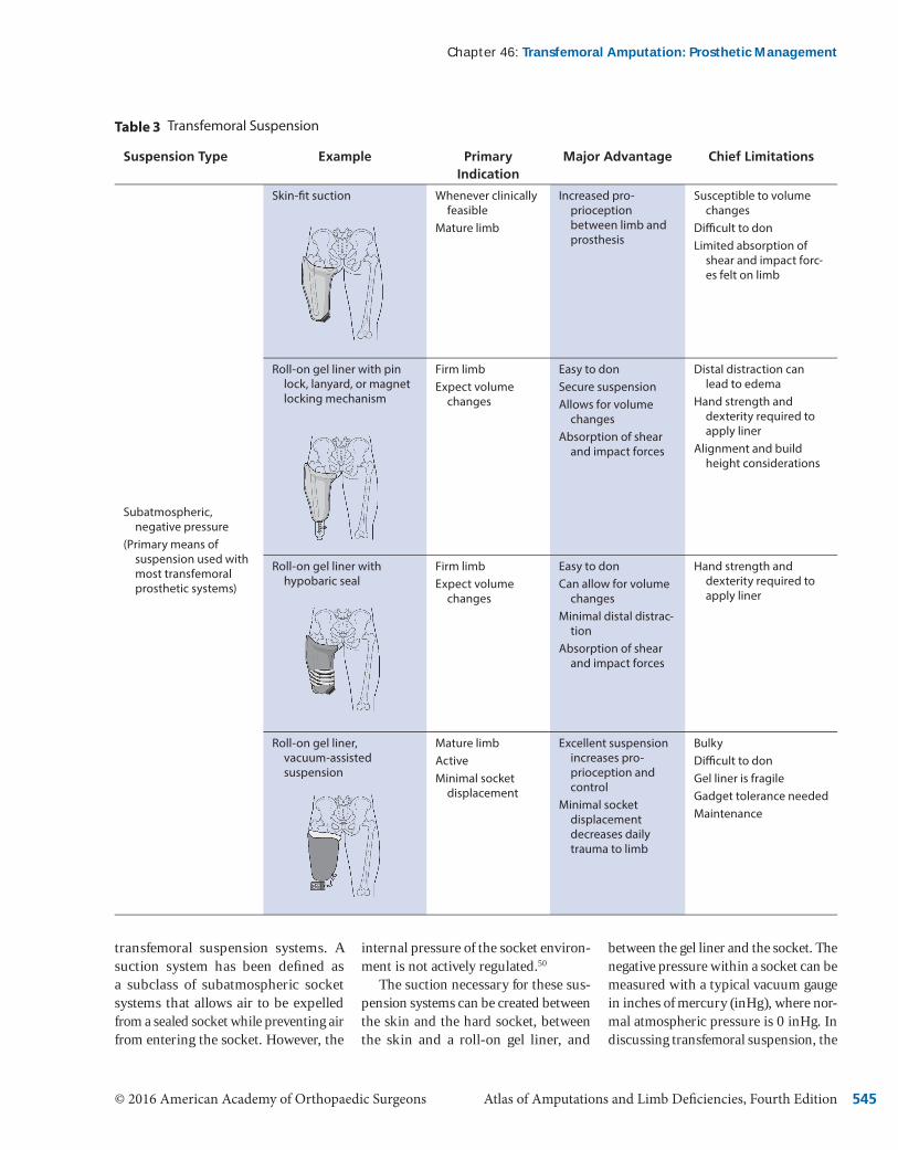
Current suspension systems being used at the transfemoral level are gen-erally classifi ed as subatmospheric, negative-pressure, and belt-type sys-tems. Subatmospheric systems use some level of negative atmospheric pressure combined with surface ten-sion to maintain the transfemoral sock-et on the residual limb. Subcategories of subatmospheric designs include skin-fi t suction, roll-on liners with various locking mechanisms, roll-on liners with a hypobaric sealing mem-brane, and vacuum-assisted suspen-sion. Belt-type systems use positive, superiorly directed forces created by a strapping system secured around the pelvis. Subcategories of belt systems include the Silesian belt, elastic belt suspension, and hip joint and pelvic belt suspension (Table 3).
Subatmospheric SuspensionSubatmospheric suspension provided by skin suction or a roll-on gel liner is the most prevalent type of suspension design.33 These systems work by com-bining friction with a negative pressure differential within the socket to main-tain suspension of the prosthesis on the residual limb. In the literature, the term “suction” is used synonymously with the term “vacuum” when discussing
Section 3 : Lower Limb
© 2016 American Academy of Orthopaedic Surgeons Atlas of Amputations and Limb Defi ciencies, Fourth Edition 545
transfemoral suspension systems. A suction system has been defi ned as a subclass of subatmospheric socket systems that allows air to be expelled from a sealed socket while preventing air from entering the socket. However, the
internal pressure of the socket environ-ment is not actively regulated.50
The suction necessary for these sus-pension systems can be created between the skin and the hard socket, between the skin and a roll-on gel liner, and
between the gel liner and the socket. The negative pressure within a socket can be measured with a typical vacuum gauge in inches of mercury (inHg), where nor-mal atmospheric pressure is 0 inHg. In discussing transfemoral suspension, the
Chapter 46 : Transfemoral Amputation: Prosthetic Management
Transfemoral Suspension
Suspension Type Example Primary Indication
Major Advantage Chief Limitations
Subatmospheric, negative pressure
(Primary means of suspension used with most transfemoral prosthetic systems)
Skin-fi t suction Whenever clinically feasible
Mature limb
Increased pro-prioception between limb and prosthesis
Susceptible to volume changes
Diffi cult to donLimited absorption of
shear and impact forc-es felt on limb
Roll-on gel liner with pin lock, lanyard, or magnet locking mechanism
Firm limbExpect volume
changes
Easy to donSecure suspensionAllows for volume
changesAbsorption of shear
and impact forces
Distal distraction can lead to edema
Hand strength and dexterity required to apply liner
Alignment and build height considerations
Roll-on gel liner with hypobaric seal
Firm limbExpect volume
changes
Easy to donCan allow for volume
changesMinimal distal distrac-
tionAbsorption of shear
and impact forces
Hand strength and dexterity required to apply liner
Roll-on gel liner, vacuum-assisted suspensionp
Mature limbActiveMinimal socket
displacement
Excellent suspension increases pro-prioception and control
Minimal socket displacement decreases daily trauma to limb
BulkyDiffi cult to donGel liner is fragileGadget tolerance neededMaintenance
Table 3

Atlas of Amputations and Limb Defi ciencies, Fourth Edition © 2016 American Academy of Orthopaedic Surgeons 546
larger the negative number the greater is the suspension force (−30 inHg rep-resents an absolute vacuum).
The original transfemoral suction suspension designs were used within a skin-fi t socket where the suction was created simply between the skin and the inner socket wall.51 Basic suction suspension systems are characterized as low, negative-pressure systems, with readings in the 0 to −8 inHg range. During weight bearing, these systems have a vacuum reading of 0 inHg. During ambulation, the vacuum reading increases in value through swing phase as the momentum of the advancing limb and weight of the prosthesis attempt to distract the prosthesis from the limb.
The greater the inertial forces generated in swing, the greater these distractive forces, thus requiring higher negative pressures to hold the socket in place.
Suction Suspension: Skin-FitSkin-fi t suction suspension has the benefi t of direct skin contact with the socket, allowing high levels of pro-prioceptive feedback to the user. The skin moves with the socket, allowing the user to quickly perceive and react to small changes in socket position. Proximal, circumferential socket re-ductions create a seal against the skin that prevents air from entering the socket, thereby permitting suction to occur during swing phase. The skin
also creates surface tension along the inner socket walls that further resists some of the distraction forces felt during swing. Typically, a one-way expulsion valve is located distally on the trans-femoral socket that permits air to escape during weight bearing while preventing air from entering during swing phase. For skin-fi t suction suspension systems, the internal pressure clinical readings have been found to be approximately −8 inHg during the swing phase.
The individual generally dons the prosthesis by initially applying a don-ning sleeve over the residual limb and feeding the loose end of the sleeve through the open distal valve hole. The sleeve breaks the surface tension
Section 3 : Lower Limb
(continued)
Suspension Type Example Primary Indication
Major Advantage Chief Limitations
Belts(Typically used as
secondary or auxiliary suspension; primary suspension only when negative atmospheric pressure cannot be used)
Silesiansian Limit socket rotation
Volume changesAuxiliary suspen-
sion
Firm belt for secure feel
AdjustableCan be removable
Minimal suspensionHand strength and
dexterity to donPressure around the
pelvisDiffi cult to clean
Elastic suspensionstic suspension Reduce socket rotation
Volume changesAuxiliary suspen-
sion
FlexibleAdjustableRemovable
Minimal suspensionElastic suspensionHand strength and
dexterity to donWarm around the pelvisDiffi cult to clean
Hip joint and pelvic belt Short residual limbsWeak hip abductorsLow levels of volun-
tary control
Maximum coronal support
Belt may be uncomfort-able
Migrates when sittingMinimal suspensionDiffi cult to clean
Table 3

© 2016 American Academy of Orthopaedic Surgeons Atlas of Amputations and Limb Defi ciencies, Fourth Edition 547
between the socket and the skin, allow-ing the individual to seat the limb inside the socket while pulling proximal soft tissue into the socket.34 The sleeve is progressively and fully extracted from the socket. With the limb fully seated, the one-way air valve is installed in place.
The disadvantages of skin-fi t suc-tion suspension systems include dif-fi culties with donning, comparatively poor mitigation of shear forces, and poor accommodation of residual limb volume fl uctuations. Successful donning of a skin-fi t suction suspension system requires strength and balance because the soft tissue needs to be pulled into the socket using a donning sleeve; this may be diffi cult for some users to manage. Scar tissue and invaginations represent another potential contraindications be-cause shear forces are typically not well tolerated by these clinical presentations and there is potential for skin break-down if the skin is not well protected and/or padded. Because skin-fi t suction requires the maintenance of a proximal, air-tight seal against the skin, even small changes in limb size caused by a change in weight or edema can compromise suspension.
Suction Suspension: Roll-On Gel Liners and Locking MechanismsRoll-on gel liners, when used as an in-terface, absorb shear and impact forces acting on the limb, stabilize soft tissue, and accommodate volume fl uctuations. As with skin-fi t suspension systems, lin-ers are held in place by a combination of suction and surface tension and may also be used as a means of suspension with the attachment of a distal locking mechanism such as a pin, lanyard, or magnet.
To don these systems, the user rolls on the liner, inserts his or her limb into the socket, and engages a locking mech-anism that is typically embedded in the distal aspect of the socket. Locking mechanisms include pins, lanyards, or
magnets. The donning of such systems is generally much quicker compared with skin-fi t suction suspension sys-tems. In addition, socks can be worn over the liner to accommodate volume changes without a loss of suspension.
Disadvantages of using roll-on liners in a transfemoral prosthesis include a minimum level of hand strength and dexterity for correct donning, the po-tential for tearing the somewhat fragile liners because of improper handling and sustained use, and the need for liner replacement if damage occurs. Roll-on liners also require consistently good hygiene to reduce odor and maintain cleanliness.
Roll-On Gel Liners: Hypobaric and Vacuum-Assisted SuspensionSuction suspension with roll-on liners can be accomplished by direct contact with the liner against the socket wall (similar to skin-fi t suspension) or with the use of hypobaric sealing mem-branes. Roll-on liners that use suction for suspension tend to have less distal distraction and minimized socket ro-tation compared with those that use a distal locking mechanism.
As is the case with skin-fi t suction, these roll-on liner systems use negative pressure and surface tension to maintain suspension. To fully seat the residual limb and liner into the socket, the sur-face tension must be reduced, typically with the use of isopropyl alcohol in lieu of a donning sleeve. The liner is rolled on over the residual limb, alcohol is sprayed on the liner, and the limb and liner are slipped into the socket and engage against the inner socket wall as the alcohol quickly evaporates. The resultant seal maintains the pressure differential within the socket.
This variation in roll-on liner use can be incorporated with either simple suction or vacuum-assisted suspension. The two suspension methods differ in the internal socket pressure while stand-ing. In simple suction suspension, the
internal socket pressure is 0 inHg, whereas socket pressure with vacu-um-assisted suspension is less than 0 inHg, and it can be as low as −25 inHg. Both systems use an expulsion valve to maintain the pressure differential, with vacuum-assisted suspension also using an external mechanism to draw air from the socket. Although suction systems have a negative pressure environment in swing only, vacuum-assisted systems have a continual negative pressure en-vironment through stance and swing.
Vacuum-assisted suspension has been slow to gain acceptance in trans-femoral applications.52 This may be the result of complicated fabrication and donning processes and diffi culties in maintaining a proximal vacuum seal. However, modern material advances, creative techniques, and design vari-ations are making vacuum-assisted suspension a more viable choice for transfemoral applications. Anecdotal reports indicate that these systems work well for individuals with longer residual limbs and high voluntary control.49
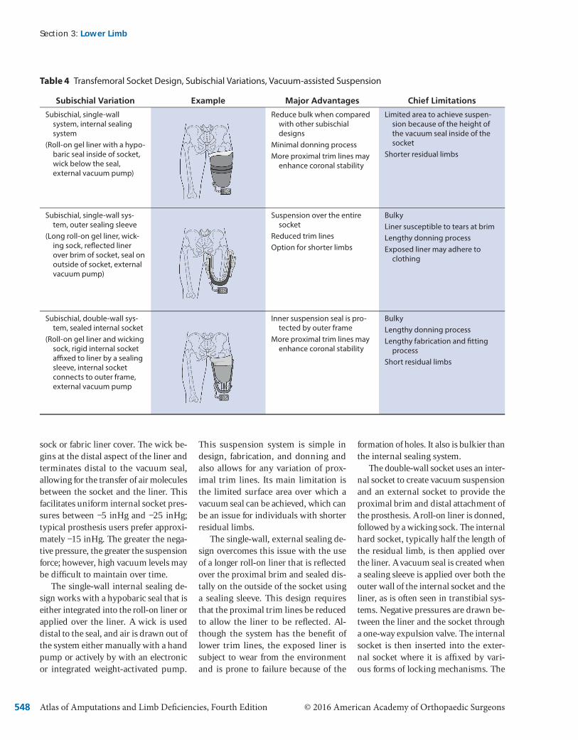
The three basic subischial socket designs that incorporate vacuum-as-sisted suspension are the single-wall internal sealing system, the single-wall external sealing system, and the dou-ble-wall internal sealing system (Ta-ble 4). Although these three designs each have advantages and limitations, all use a roll-on gel liner as an interface and utilize the creation of high levels of vacuum-assisted suspension between the liner and the socket rather than the skin. Although skin is compatible with basic suction suspension, it is porous and irregular in shape, making it a poor surface for maintaining elevated levels of negative pressure. Gel liners have a smooth, fl exible, nonporous surface that allows for a vacuum seal to be main-tained throughout ambulation, while sitting, and during participation in ac-tivities of daily living.
All three subischial socket design systems also use a wick in the form of a
Chapter 46 : Transfemoral Amputation: Prosthetic Management
Atlas of Amputations and Limb Defi ciencies, Fourth Edition © 2016 American Academy of Orthopaedic Surgeons 548
sock or fabric liner cover. The wick be-gins at the distal aspect of the liner and terminates distal to the vacuum seal, allowing for the transfer of air molecules between the socket and the liner. This facilitates uniform internal socket pres-sures between −5 inHg and −25 inHg; typical prosthesis users prefer approxi-mately −15 inHg. The greater the nega-tive pressure, the greater the suspension force; however, high vacuum levels may be diffi cult to maintain over time.
The single-wall internal sealing de-sign works with a hypobaric seal that is either integrated into the roll-on liner or applied over the liner. A wick is used distal to the seal, and air is drawn out of the system either manually with a hand pump or actively by with an electronic or integrated weight-activated pump.
This suspension system is simple in design, fabrication, and donning and also allows for any variation of prox-imal trim lines. Its main limitation is the limited surface area over which a vacuum seal can be achieved, which can be an issue for individuals with shorter residual limbs.
The single-wall, external sealing de-sign overcomes this issue with the use of a longer roll-on liner that is refl ected over the proximal brim and sealed dis-tally on the outside of the socket using a sealing sleeve. This design requires that the proximal trim lines be reduced to allow the liner to be refl ected. Al-though the system has the benefi t of lower trim lines, the exposed liner is subject to wear from the environment and is prone to failure because of the
formation of holes. It also is bulkier than the internal sealing system.
The double-wall socket uses an inter-nal socket to create vacuum suspension and an external socket to provide the proximal brim and distal attachment of the prosthesis. A roll-on liner is donned, followed by a wicking sock. The internal hard socket, typically half the length of the residual limb, is then applied over the liner. A vacuum seal is created when a sealing sleeve is applied over both the outer wall of the internal socket and the liner, as is often seen in transtibial sys-tems. Negative pressures are drawn be-tween the liner and the socket through a one-way expulsion valve. The internal socket is then inserted into the exter-nal socket where it is affi xed by vari-ous forms of locking mechanisms. The
Section 3 : Lower Limb
Transfemoral Socket Design, Subischial Variations, Vacuum-assisted Suspension
Subischial Variation Example Major Advantages Chief Limitations
Subischial, single-wall system, internal sealing system
(Roll-on gel liner with a hypo-baric seal inside of socket, wick below the seal, external vacuum pump)
Reduce bulk when compared with other subischial designs
Minimal donning processMore proximal trim lines may
enhance coronal stability
Limited area to achieve suspen-sion because of the height of the vacuum seal inside of the socket
Shorter residual limbs
Subischial, single-wall sys-tem, outer sealing sleeve
(Long roll-on gel liner, wick-ing sock, refl ected liner over brim of socket, seal on outside of socket, external vacuum pump)
Suspension over the entire socket
Reduced trim linesOption for shorter limbs
BulkyLiner susceptible to tears at brimLengthy donning processExposed liner may adhere to
clothing
Subischial, double-wall sys-tem, sealed internal socket
(Roll-on gel liner and wicking sock, rigid internal socket affi xed to liner by a sealing sleeve, internal socket connects to outer frame, external vacuum pump
Inner suspension seal is pro-tected by outer frame
More proximal trim lines may enhance coronal stability
BulkyLengthy donning processLengthy fabrication and fi tting
processShort residual limbs
Table 4

© 2016 American Academy of Orthopaedic Surgeons Atlas of Amputations and Limb Defi ciencies, Fourth Edition 549
major limitations of this design are its bulk, weight, and complicated donning and fabrication processes.
Belt-Type or Auxiliary SuspensionBelt-type suspension offers convenience over performance. These systems are easy to don but offer minimal primary suspension. Belt-type suspension sys-tems are primarily used to provide sec-ondary or auxiliary suspension and aid in control of the device. The three main types of belt-type suspension systems are the Silesian belt, elastic suspension, and the hip joint and pelvic belt (Ta-ble 3). Silesian and elastic systems are soft belt systems that can be attached to the socket to help reduce rotation and provide minimal suspension. For individuals who ambulate at a minimal cadence and require a socket system that is both easy to don and allows for free movement of air, these suspension systems may be an adequate primary suspension option. Alternatively, for in-dividuals who require greater coronal stabilization because of a short residual limb or lack of abductor muscle control, a hip joint and pelvic belt can be used. This system provides maximal stability against lateral socket motion but pro-vides minimal suspension.
Component ConsiderationsProsthetic Knee ConsiderationsBecause an individual with a transfem-oral prosthesis has no direct musculo-skeletal connection to the prosthetic knee or foot, the most optimal compo-nents must be selected. If the prosthetic knee unit is to simulate the function of the anatomic knee it must provide sta-bility in early stance, allow for shock absorption while maintaining a lowered center of mass through midstance, pro-vide stability through terminal stance, allow a smooth transition into swing phase, limit initial swing phase fl exion across a range of cadences, advance the limb through midswing, and smoothly decelerate at terminal swing.22
The fi rst concern in knee compo-nent selection should be stability in early stance. If the individual has lim-ited voluntary control, the knee unit must have inherent stability, which can be variously achieved through mechanical linkages, breaking mech-anisms, or hydraulic dampening con-trol. Recently, the addition of sensors and microprocessor control units has demonstrated an increased ability to allow safe ambulation, reduced cogni-tive dedication to controlling the knee unit, increased gait effi ciency, and in-creased overall user confi dence with the prosthesis.53
Another concern in knee component selection is the ability of the knee to transition from stance to swing phase. The methodology varies by which the prosthetic knee “knows” when to tran-sition from stable load bearing in stance phase to less restricted motion that will allow swing phase fl exion. Mechanically controlled knee units typically rely on a transfer of load or the mechanical knee angle to initiate this transition. In con-trast, microprocessor-controlled knee units use algorithms based on input received from load sensors, accelerom-eters, gyroscopes, and joint angles. Be-cause of this nuanced level of regulation, microprocessor-controlled knee units allow for more controlled prosthetic ambulation, enabling the user to confi -dently address changes in the environ-ment, such as walking down slopes or ramps, movements in confi ned spaces, descending or ascending stairs, and walking backward. These situations il-lustrate scenarios in which mechanically controlled knees often fail to provide consistent support and which require the prosthesis user to be cognizant of environmental changes.
Prosthetic Foot ConsiderationsWhen selecting a prosthetic foot for an individual with a transfemoral amputa-tion, an initial concern is the infl uence of the foot on the knee fl exion moment
in early stance. If the individual has limited voluntary control, the prosthet-ic foot should reduce the knee fl exion moment. This can be accomplished with a soft heel component in the prosthetic foot itself or by altering the alignment of the foot relative to the socket. The next concern is the transition from stance to swing phase where the foot should generally enhance late stance stability to allow the user to take an adequate step with the contralateral limb. The length, stiffness, and design of the keel, along with alternations in alignment will af-fect stability in this late stance phase.
Additional Component ConsiderationsWith the anatomic knee and foot ab-sent, users of transfemoral devices are missing elements of rotation, shock ab-sorption, and stance-phase knee fl exion. Additional components of transfemoral prostheses can address these missing anatomic elements. Positional rotation units allow the prosthesis user to spin the prosthetic components distal to an adaptor. The function of these units is optimized when they are applied on the distal aspect of the socket and proximal to the knee. This allows the user to cross his or her legs, more easily tie shoes, don pants, and enter the front seat of a car. Torque absorption units can be com-bined with shock absorbers to reduce the shear and impact forces felt on the residual limb. Although these compo-nents are effective, they add weight, cost, and spatial considerations to the overall design of the prosthesis.
Stance fl exion, the 15° to 20° of knee fl exion necessary for optimized gait, is achieved during loading response,22 and it is often a desired feature when cre-ating transfemoral prosthetic devices. However, this amount of knee fl exion in early stance can induce a sensation of instability for many individuals with a transfemoral amputation. Prosthet-ic stance fl exion is variously obtained through the design of the knee frame,
Chapter 46 : Transfemoral Amputation: Prosthetic Management

Atlas of Amputations and Limb Defi ciencies, Fourth Edition © 2016 American Academy of Orthopaedic Surgeons 550
compressive bumpers, and hydraulic cylinders.
Alignment ConsiderationsThe principles of transfemoral prosthe-sis alignment have altered little over time. In 1955 Radcliffe14 addressed transfemoral alignment considerations in his statement that the artifi cial limb “… must provide both adequate sup-port and a natural-appearing gait with as modest consumption of energy as possible.” These standards have not appreciably changed. Prosthetists at-tempt to create a stable and effective transfemoral gait pattern with proper socket fi t; effective suspension; and diligence in bench, static, and dynamic alignments.
Before it is fi tted to a patient, the prosthesis is set up in bench align-ment, which refl ects the individual’s
hip fl exion, adduction attitude, and transverse limb orientation. The sock-et is generally set in a fl exion angle 5° greater than the individual’s maximum hip extension. This added hip fl exion permits the user to take an adequate step with the contralateral limb and puts a mild stretch on the hip extensor mus-cles to allow them to be more effi cient in early stance.14,29,30,37,40
The transfemoral socket is also set to match the individual’s recorded adduction orientation. This will align the femur under the hip joint and put a mild stretch on the gluteus medius, increasing effi ciency during single-limb support.54 Setting the proper amount of socket adduction also reduces the ten-dency for proximal lateral gapping of the socket and helps to maintain a narrow base of support.29,40 Transverse orienta-tion is determined by the user’s line of
progression and the necessity to mini-mize transverse plane gait deviations. This orientation is especially important for proper fi tting of IC sockets.
With the socket in the proper ori-entation, the focus is on the place-ment of the prosthetic knee and foot. In able-bodied individuals, coronal alignment of the hip joint is typically directly over the knee and ankle joints (Figure 3, A). For initial bench align-ment of the transfemoral prosthesis, the actual hip joint cannot be used as a ref-erence point because it cannot be locat-ed on the prosthetic socket. However, locating a point on the socket brim that is 1 inch (2.54 cm) lateral to the location of the ischium will provide a reasonable approximation. The prosthetic knee and ankle joints are placed directly below this identifi ed point. The initial coronal bench alignment allows for stability in
Section 3 : Lower Limb
Illustrations show the process of initial coronal alignment for placement of the prosthetic knee and foot. A, Posterior view of anatomic alignment in the coronal plane. The hip joint aligns over the knee joint and the ankle joint. B, Because the hip joint is diffi cult to represent in transfem-oral alignment, the location of the ischium (X) is used instead. For longer residual limbs, the coronal alignment line begins 1 inch (2.54 cm) lateral to the ischium, then continues distally through the posterior bisection of the prosthetic knee and the posterior bisection of the prosthetic foot. C, For shorter residual limbs or individuals with lower levels of voluntary control, the coronal alignment line is shifted laterally, closer to the bisection of the prosthetic socket, but never more lateral than the bisection of the socket. D, A completed transfemoral alignment with the socket set at the initial adduction angle (heavy black line) and the connecting pylons attached to the socket, knee, and foot.
Figure 3
© 2016 American Academy of Orthopaedic Surgeons Atlas of Amputations and Limb Defi ciencies, Fourth Edition 551
double-limb stance, induces a modest lateral thrust in single-limb stance, and achieves a narrow 2-inch (5.08-cm) base of support (Figure 3, B). The prosthetic knee and ankle should be
placed more laterally under the socket for shorter residual limbs or in individu-als with compromised voluntary control (Figure 3, C). However, this necessary accommodation will increase energy
expenditure by inducing a wider base of support.
In able-bodied individuals, the sagit-tal plane alignment of the ground reac-tive force is posterior to the hip joint and
Chapter 46 : Transfemoral Amputation: Prosthetic Management
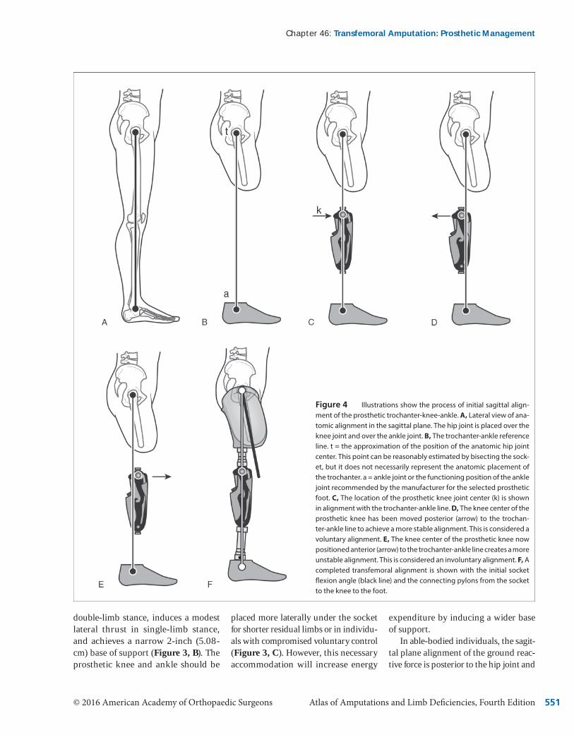
Illustrations show the process of initial sagittal align-ment of the prosthetic trochanter-knee-ankle. A, Lateral view of ana-tomic alignment in the sagittal plane. The hip joint is placed over the knee joint and over the ankle joint. B, The trochanter-ankle reference line. t = the approximation of the position of the anatomic hip joint center. This point can be reasonably estimated by bisecting the sock-et, but it does not necessarily represent the anatomic placement of the trochanter. a = ankle joint or the functioning position of the ankle joint recommended by the manufacturer for the selected prosthetic foot. C, The location of the prosthetic knee joint center (k) is shown in alignment with the trochanter-ankle line. D, The knee center of the prosthetic knee has been moved posterior (arrow) to the trochan-ter-ankle line to achieve a more stable alignment. This is considered a voluntary alignment. E, The knee center of the prosthetic knee now positioned anterior (arrow) to the trochanter-ankle line creates a more unstable alignment. This is considered an involuntary alignment. F, A completed transfemoral alignment is shown with the initial socket fl exion angle (black line) and the connecting pylons from the socket to the knee to the foot.
Figure 4

Atlas of Amputations and Limb Deficiencies, Fourth Edition © 2016 American Academy of Orthopaedic Surgeons552
anterior to the knee and ankle (Figure 4, A). This anatomic alignment allows the prosthesis user to stand with minimal energy expenditure. Because the ana-tomic hip joint cannot be used as a point of reference on the prosthetic socket, the apex of the greater trochanter is used. For bench sagittal plane alignment, a simulated reference line is used to create a stable prosthetic alignment. This line is called the trochanter-knee-ankle line. To understand the use of the trochan-ter-knee-ankle reference line, a single axis knee and single axis foot will be as-sumed, because these components have very little inherent stability and require that the stability of the overall prosthetic system be derived by the alignment of the socket relative to the knee and ankle components.
The trochanter-knee-ankle line be-gins by determining a reference point for the trochanter and approximating the position of the hip joint. This point can be reasonably estimated by bisect-ing the socket in the sagittal plane at its most proximal aspect (Figure 4, B). This is followed by the placement of the prosthetic ankle joint, a reference point that differs for every prosthetic foot and is identified within individual manufac-turer’s guidelines. When the trochan-ter and prosthetic and ankle reference points are vertically aligned (Figure 4, B), the prosthetic knee is set at its prop-er height and located according to the manufacturer’s recommendation for the knee center’s sagittal reference point. This point may be posterior, through, or anterior to the trochanter-ankle line (Figure 4, C). Placing knee center poste-rior to the line creates a safe alignment, because the individual’s weight and the ground reaction force keep the knee locked in extension. This also can be described as an involuntary alignment, because no voluntary control is required to keep the knee in extension (Figure 4, D). In contrast, placing knee center ante-rior to the trochanter-ankle line creates an alignment in which the individual
has to voluntarily control the sagittal stability of the knee. This alignment is also seen with knee units possessing inherent stability because it facilitates early stance flexion and permits easier initiation of swing phase knee flexion in late stance (Figure 4, E). If the knee center point is directly on the trochan-ter-ankle line, it is considered to be on “trigger,” where the system may be in voluntary or involuntary alignment de-pending on the placement of the pros-thetic foot with each step (Figure 4, F).
In the transverse plane, the pros-thetic knee is externally rotated 5° to compensate for the natural 5° of internal socket rotation that will occur during swing phase. This rotation ensures that the knee will flex in the line of progres-sion during swing. For individuals who walk faster, the amount of internal ro-tation will increase, and the initial ex-ternal knee rotation should be larger.
When bench alignment is complete, the prosthesis is donned and static or standing alignment is assessed. The foot should be flat on the floor with 2 to 4 inches (5.08 to 10.16 cm) of base sup-port. The knee should be extended and safe with socket flexion, with adduction and rotation matching the individual’s limb orientation. Generally, if bench alignment conditions were observed, minimal adjustments will need to be made to achieve a proper static fit. Any accommodative changes in flexion or adduction will change the position of the socket over the knee and foot, which will alter the stability of the system. In such instances, the proper trochan-ter-knee-ankle alignment should be reestablished before ambulation begins.
Because every prosthetic knee and foot has different triggers to transition from stance to swing control, the pros-thesis user must be made aware of how each component functions before am-bulation is attempted. The prosthesis user should be observed and instructed on proper techniques while functions such as sitting, bending the knee, and
advancing the limb are practiced in a safe environment (such as with parallel bar support before ambulation). During dynamic alignment, the prosthetist will work to optimize gait and minimize energy expenditure by making incre-mental changes to the alignment and working with a therapist to focus on enhancing muscle strength and range of motion.
SummaryGreat technological advances have been made in transfemoral prosthetic sockets, components, and suspension systems in recent years. However, it must be un-derstood that there is no single socket design, alignment, or prosthetic system that will be optimal for all individuals with transfemoral amputation. There is a need for prosthetists to continually de-velop their clinical and technical skills to provide the most appropriate device and the best fit for each patient.
The team must address issues of en-ergy expenditure, body image, levels of voluntary control, and socket fit in creating the treatment plan, and they should have an intimate knowledge of appropriate sockets designs, suspension systems, components, and alignment considerations. Clinical experience, knowledge of evolving clinical stan-dards, the use of available evidence, and the incorporation of appropriate outcome measures also will assist the rehabilitation team in providing optimal care to their patients.
References 1. Ziegler-Graham K, MacKenzie EJ,
Ephraim PL, Travison TG, Brook-meyer R: Estimating the prevalence of limb loss in the United States: 2005 to 2050. Arch Phys Med Rehabil 2008;89(3):422-429. Medline DOI
2. Belatti DA, Phisitkul P: Declines in lower extremity amputation in the US Medicare population, 2000-2010.
Section 3: Lower Limb

© 2016 American Academy of Orthopaedic Surgeons Atlas of Amputations and Limb Deficiencies, Fourth Edition 553
Foot Ankle Int 2013;34(7):923-931. Medline DOI
3. National Center for Health Statistics: Health, United States, 2004, With Chartbook on Trends in the Health of Americans. Hyattsville, Maryland, 2004. Available at: http://www.cdc.gov/nchs/data/hus/hus04.pdf. Ac-cessed May 1, 2015.
4. Esquenazi A: Amputation rehabilita-tion and prosthetic restoration: From surgery to community reintegration. Disabil Rehabil 2004;26(14-15):831-836. Medline DOI
5. Dillingham TR, Pezzin LE, Mac-Kenzie EJ: Limb amputation and limb deficiency: Epidemiology and recent trends in the United States. South Med J 2002;95(8):875-883. Medline
6. Dodson A, El-Gamil A, Shimer M, DaVanzo J: Retrospective Cohort Study of the Economic Value of Or-thotic and Prosthetic Services Among Medicare Beneficiaries: Final Report. Vienna, VA, Dobson DaVanzo & As-sociates, 2013, pp. 20-24. Available at: http://www.amputee-coalition.org/content/documents/dobson-davan-zo-report.pdf. Accessed May 1, 2015.
7. Practice Analysis of Certified Practi-tioners in the Disciplines of Orthotics and Prosthetics. Alexandria, VA, American Board for Certification in Orthotics, Prosthetics & Pedorthics, 2015, p 37. Available at: http://www.abcop.org/individual-certification/Documents/ABC%20Practice%20Analysis%20of%20the%20Disci-pline%20of%20Orthotics%20and%20Prosthetics.pdf. Accessed July 13, 2015.
8. Marks AA: A Treatise on Artificial Limbs With Rubber Hands and Feet. New York, NY, AA Marks, 1901.
9. Canty TJ, Ware RM: Suction socket for above knee prosthesis. U S Nav Med Bull 1949;49(2):216-233. Medline
10. Pritham CH: Workshop on teach-ing materials for above-knee
socket variants. J Prosthet Orthot 1988;1(1):50-67. DOI
11. Gholizadeh H, Abu Osman NA, Eshraghi A, Ali S: Transfemoral prosthesis suspension systems: A sys-tematic review of the literature. Am J Phys Med Rehabil 2014;93(9):809-823. Medline DOI
12. Palmar BF, inventor. Artificial leg. US patent 4834. November 4, 1846.
13. Anderson MH: Professional edu-cation: A nine-year report. Orthop Prosthet Appl J 1961:123-135.
14. Radcliffe CW: Functional consider-ations in the fitting of above-knee prostheses. Artif Limbs 1955;2(1):35-60. Medline
15. Anderson MH, Sollars RE: Manual of Above-Knee Prosthetics for Prosthe-tists. Los Angeles, CA, UCLA Pros-thetics Education Program, 1956.
16. Redhead RG: Total surface bearing self suspending above-knee sockets. Prosthet Orthot Int 1979;3(3):126-136. Medline
17. Lusardi MM, Jorge M, Nielsen CC: Orthotics and Prosthetics in Rehabil-itation. St. Louis, MO, Elsevier, 2013, pp 652-678.
18. Klotz R, Colobert B, Botino M, Permentiers I: Influence of different types of sockets on the range of mo-tion of the hip joint by the transfem-oral amputee. Ann Phys Rehabil Med 2011;54(7):399-410. Medline DOI
19. Gailey RS, Lawrence D, Burditt C, Spyropoulos P, Newell C, Nash MS: The CAT-CAM socket and quadrilat-eral socket: A comparison of energy cost during ambulation. Prosthet Orthot Int 1993;17(2):95-100. Medline
20. Chin T, Oyabu H, Maeda Y, Takase I, Machida K: Energy consump-tion during prosthetic walking and wheelchair locomotion by elderly hip disarticulation amputees. Am J Phys Med Rehabil 2009;88(5):399-403. Medline DOI
21. Highsmith MJ, Schulz BW, Hart-Hughes S, et al: Differences in the spatiotemporal parameters of trans-tibial and transfemoral amputee gait. J Prosthet Orthot 2010;22:26-30. DOI
22. Perry J: Gait Analysis: Normal and Pathological Function. Thorofare, NJ, SLACK, 2010.
23. Deans SA, McFadyen AK, Rowe PJ: Physical activity and quality of life: A study of a lower-limb ampu-tee population. Prosthet Orthot Int 2008;32(2):186-200. Medline DOI
24. Horgan O, MacLachlan M: Psy-chosocial adjustment to lower-limb amputation: A review. Disabil Rehabil 2004;26(14-15):837-850. Medline DOI
25. Schoppen T, Boonstra A, Groothoff JW, de Vries J, Göeken LN, Eisma WH: Physical, mental, and social predictors of functional outcome in unilateral lower-limb amputees. Arch Phys Med Rehabil 2003;84(6):803-811. Medline DOI
26. Gallagher P, Horgan O, Franchignoni F, Giordano A, MacLachlan M: Body image in people with lower-limb amputation: A Rasch analysis of the Amputee Body Image Scale. Am J Phys Med Rehabil 2007;86(3):205-215. Medline DOI
27. Ephraim PL, MacKenzie EJ, Wege-ner ST, Dillingham TR, Pezzin LE: Environmental barriers experienced by amputees: The Craig Hospital inventory of environmental factors. Short form. Arch Phys Med Rehabil 2006;87(3):328-333. Medline DOI
28. Pezzin LE, Dillingham TR, Macken-zie EJ, Ephraim P, Rossbach P: Use and satisfaction with prosthetic limb devices and related services. Arch Phys Med Rehabil 2004;85(5):723-729. Medline DOI
29. Staats TB: Ischial Containment Sock-et Design: Above Knee Amputation Prosthesis. Master Model Modifica-tion Manual. Carson, CA, California State University Dominguez Hills
Chapter 46: Transfemoral Amputation: Prosthetic Management

Atlas of Amputations and Limb Deficiencies, Fourth Edition © 2016 American Academy of Orthopaedic Surgeons554
Orthotics and Prosthetics Program, 2002.
30. Hoyt C, Littig D, Lundt J, Staats TB: The UCLA CAT-CAM Above Knee Socket, ed 3. Los Angeles, CA, University California Los Angeles Prosthetics Education and Research Program, 1987.
31. Kamali M, Karimi MT, Eshraghi A, Omar H: Influential factors in stabili-ty of lower-limb amputees. Am J Phys Med Rehabil 2013;92(12):1110-1118. Medline DOI
32. Staat T, Lundt J: The UCLA Total Surface Bearing Suction Below-Knee Prosthesis. Clin Prosthet Orthot 1987;11(3):118-138.
33. Highsmith JT, Highsmith MJ: Com-mon skin pathologies in LE pros-thesis users: Review article. JAAPA 2007;20(11): 33-36, 47. Medline
34. Pasquina PF, Cooper RA, eds: Care of the Combat Amputee. Washington, DC, Office of the Surgeon General, Borden Institute, 2009, pp 553-580.
35. Siriwardena GJ, Bertrand PV: Factors influencing rehabilitation of arteriosclerotic lower limb amputees. J Rehabil Res Dev 1991;28(3):35-44. Medline DOI
36. Munin MC, Espejo-De Guzman MC, Boninger ML, Fitzgerald SG, Penrod LE, Singh J: Predictive factors for successful early prosthetic ambula-tion among lower-limb amputees. J Rehabil Res Dev 2001;38(4):379-384. Medline
37. Radcliffe CW: The Knud Jansen lecture: Above-knee prosthetics. Prosthet Orthot Int 1977;1(3):146-160. Medline
38. Practice Analysis of Certified Practi-tioners in the Disciplines of Orthotics and Prosthetics. Alexandria, VA, American Board for Certification in Orthotics, Prosthetics & Pedorthics, 2000, p 45.
39. Long IA: Normal shape-normal alignment (NSNA) above knee
prosthesis. Clin Prosthet Orthot 1985;9(4):9-14.
40. Muller MD: Transfemoral Ischial Containment (IC) Laboratory Manu-al. Carson, CA, California State Uni-versity Dominguez Hills Orthotics and Prosthetics Program, 2013.
41. Neumann ES, Wong JS, Drollinger RL: Concepts of pressure in an ischial containment socket: Measurement. J Prosthet Orthot 2005;17:2-11. DOI
42. Dillon M: Ischial Containment Socket for Transfemoral Amputees: A Manu-al for Assessment, Casting, Modifica-tion and Fitting. Bundoora, Australia, National Çentre for Prosthetics and Orthotics La Trobe University, 2006.
43. Kahle JT, Highsmith MJ: Transfem-oral sockets with vacuum-assisted suspension comparison of hip kinematics, socket position, contact pressure, and preference: Ischial containment versus brimless. J Re-habil Res Dev 2013;50(9):1241-1252. Medline DOI
44. Moran CW: Revolutionizing pros-thetics 2009 modular prosthetic limb-body interface: Overview of the prosthetic socket development. Available at: http://techdigest.jhuapl.edu/TD/td3003/30_3-Moran.pdf. Accessed May 1, 2015.
45. Fatone S, Caldwell R, Major M, et al: Development of sub-ischial pros-thetic sockets with vacuum-assisted suspension for highly active persons with transfemoral amputations. 2013. Available at: http://www.nupoc.northwestern.edu/research/projects/lowerlimb/dev_subischial.html. Accessed May 1, 2015.
46. Sabolich J: Contoured adducted trochanteric-controlled alignment method (CAT-CAM): Introduction and basic principles. Clin Prosthet Orthot 1985;9:15-26.
47. Traballesi M, Delussu AS, Averna T, Pellegrini R, Paradisi F, Brunelli S: Energy cost of walking in transfem-oral amputees: Comparison between
Marlo Anatomical Socket and Ischial Containment Socket. Gait Posture 2011;34(2):270-274. Medline DOI
48. Strachan E, Davis A, Wontorcik L: Stride-to-stride temporal-spatial gait variability and vacuum pressure deviation of trans-femoral ampu-tees ambulating with sub-ischial prostheses. 2011. Available at: http://www.oandp.org/publications/jop/2011/2011-07.pdf. Accessed May 1, 2015.
49. Kahle JT, Orriola JJ, Johnston W, Highsmith M: The effects of vacu-um-assisted suspension on residual limb physiology, wound healing, and function: A systematic review. Tech-nol Innov 2014;15(4):333-341. DOI
50. American Academy of Orthotist and Prosthetist Lower Limb Prosthetic Society Sub-Atmospheric Tech-nology Group: Definition of terms. Available at: http://aaop-llps.ning.com/group/SATG/page/defini-tion-of-terms-sub-atmospheric-tech-nology. Accessed August 1, 2014.
51. Haddan CC, Thomas A: Status of the above-knee suction socket in the United States. Artif Limbs 1954;12:29-39. Medline
52. Patterson S: Editorial: Experiences with negative-pressure socket design. Academy Today 2007;3(3):10-14.
53. Highsmith MJ, Kahle JT, Bongiorni DR, Sutton BS, Groer S, Kaufman KR: Safety, energy efficiency, and cost efficacy of the C-Leg for transfemoral amputees: A review of the literature. Prosthet Orthot Int 2010;34(4):362-377. Medline DOI
54. Gottschalk FA, Kourosh S, Stills M, et al: Does socket configuration influence the position of the femur in above-knee amputation? J Prosthet Orthot 1989;2:94-102. DOI
Section 3: Lower Limb