maritime engineering edition fall 2021 no
TRANSCRIPT

Fall 2021
Since 1982
98
NationalDefence
Maritime Engineering JournalCanada’s Naval Technical Forum
An in-house diesel-generator replacement for HMCS Ville de Québec
Feature Content CNTHA CNTHA News News
Inside!Inside!

The Last Corvette
The museum ship HMCS Sackville is safely back in the water following an amazing overhaul by Fleet Maintenance Facility Cape Scott in Halifax, NS. The last remaining wartime Flower-class
corvette, managed and operated by the Canadian Naval Memorial Trust, underwent extensive hull repairs to keep the ship afloat for the enjoyment of visitors for years to come.
See News Briefs page 16
Photo courtesy Sandy McClearn

Director General Maritime Equipment Program Management
Cmdre Lou Carosielli, CD
Senior EditorCapt(N) Andrew Monteiro, CDChief of Staff MEPM
NCM Editorial AdvisorsCPO1 Monika QuillanDGMEPM Unit ChiefCPO1 Herbert Connors DNPS 3-3-4, DGMEPM
Project ManagerLCdr Samuel Poulin
Production Editor/EnquiriesBrian McCullough [email protected]
Graphic Design and Production Services d2k Graphic Design & Web www.d2k.ca Tel. (819) 771-5710
Maritime Engineering Journal on Canada.ca: https://www.canada.ca/en/department-national-defence/corporate/reports-publications/maritime-engineering-journal.html
Our complete back catalogue is maintained at: https://publications.gc.ca/site/eng/9.507873/publication.html
…and by theCanadian Naval TechnicalHistory Association at: http://www.cntha.ca/publications/m-e-j/
(Established 1982) Fall 2021
98
Maritime Engineering Journal
Staff from Fleet Maintenance Facility Cape Scott in Halifax remove the old MWM 602 diesel engine from HMCS Ville de Québec's after auxiliary machinery room. (Photo courtesy FMF Cape Scott)
Commodore’s CornerA salute to the Royal Canadian Navy’s Marine Technicians by Commodore Lou Carosielli, CD .............................................................................................................. 2
ForumHave Pipes, Will Travel by LCdr Rob Waller.............................................................................................................................3
Feature ArticlesAfter Auxiliary Machinery Room Diesel-Generator Replacement on HMCS Ville de Québec by Lt(N) Michael McKenna ..............................................................................................................6
A Land Based Test Capability for the Canadian Surface Combatant Project by Stephen Harrison, Flavio Stasi and LCdr Yohan Desjardins ................................................11
BooksTitles of Interest ................................................................................................................................14
News BriefsHMCS Sackville safely back in the water ..................................................................................... 16
HMCS Fredericton Hull Insert Repair — A Team Effort by Greg Stymest, FMF Cape Scott ...................................................................................................................................17
FMF Cape Breton docks USN submarine camels by Brian McCullough, with Lt(N) Peter Summers and Ashley Evans ........................................ 20
Your Navy Today – Featured Video .............................................................................................. 22
CNTHA NewsA Few Experiences of a Young Lieutenant(N) Naval Architect by Commodore (Ret’d) W.J. Broughton .............................................................................................................23
The Maritime Engineering Journal (ISSN 0713-0058) is a NATO UNCLASSIFIED publication of the Canadian Armed Forces, published by the Director General Maritime Equipment Program Management, 101 Colonel By Drive, Ottawa, Ontario, Canada, K1A 0K2. Views expressed are those of the writers and do not necessarily reflect official opinion or policy. For all enquiries, including free subscriptions, please contact: [email protected].
To request a free subscription, change a delivery address, or cancel a subscription, please contact: [email protected].
MARITIME ENGINEERING JOURNAL NO. 98 – FALL 2021
Maritime Engineering Journal 2 Canada’s Naval Technical Forum
By Commodore Lou Carosielli, CD
COMMODORE'S CORNER
A salute to the Royal Canadian Navy’s Marine Technicians
T he delivery in July of the second of the Navy’s Arctic and offshore patrol vessels from Irving Shipbuilding—the soon-to-be-commissioned
HMCS Margaret Brooke (AOPV-431)—reminds us that even during these stressful, uncertain times, the Royal Canadian Navy (RCN) still has a mission to fulfill in maintaining capable maritime forces in support of Canadian security operations anywhere in the world at any time.
Like the decorated wartime RCN nursing sister in whose honour the ship is named, the people charged with taking our Navy’s ships to sea, and equally those who support the fleet from ashore, understand what it means to dig deep when the challenges are many, and the pats on the back are seemingly few and far between. In this sense, the RCN is extremely blessed in having a naval technical support community that is comprised of sailors, civilian employees and defence partners who are dedicated to their work, and who are extremely good at what they do. They know how to get on with the task at hand.
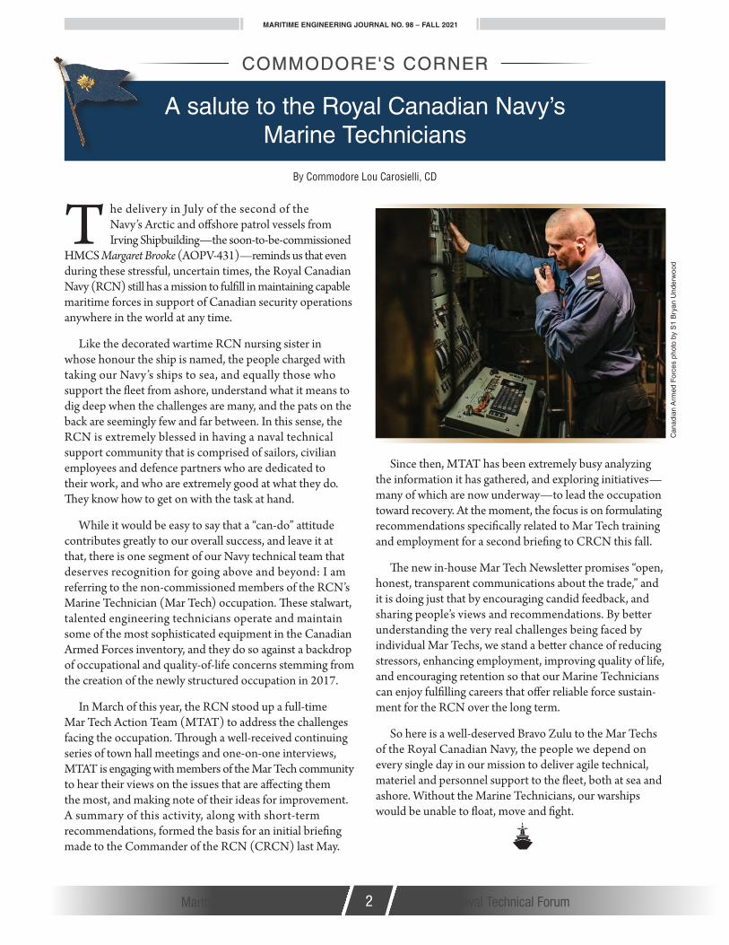
While it would be easy to say that a “can-do” attitude contributes greatly to our overall success, and leave it at that, there is one segment of our Navy technical team that deserves recognition for going above and beyond: I am referring to the non-commissioned members of the RCN’s Marine Technician (Mar Tech) occupation. These stalwart, talented engineering technicians operate and maintain some of the most sophisticated equipment in the Canadian Armed Forces inventory, and they do so against a backdrop of occupational and quality-of-life concerns stemming from the creation of the newly structured occupation in 2017.
In March of this year, the RCN stood up a full-time Mar Tech Action Team (MTAT) to address the challenges facing the occupation. Through a well-received continuing series of town hall meetings and one-on-one interviews, MTAT is engaging with members of the Mar Tech community to hear their views on the issues that are affecting them the most, and making note of their ideas for improvement. A summary of this activity, along with short-term recommendations, formed the basis for an initial briefing made to the Commander of the RCN (CRCN) last May.
Since then, MTAT has been extremely busy analyzing the information it has gathered, and exploring initiatives—many of which are now underway—to lead the occupation toward recovery. At the moment, the focus is on formulating recommendations specifically related to Mar Tech training and employment for a second briefing to CRCN this fall.
The new in-house Mar Tech Newsletter promises “open, honest, transparent communications about the trade,” and it is doing just that by encouraging candid feedback, and sharing people’s views and recommendations. By better understanding the very real challenges being faced by individual Mar Techs, we stand a better chance of reducing stressors, enhancing employment, improving quality of life, and encouraging retention so that our Marine Technicians can enjoy fulfilling careers that offer reliable force sustain-ment for the RCN over the long term.
So here is a well-deserved Bravo Zulu to the Mar Techs of the Royal Canadian Navy, the people we depend on every single day in our mission to deliver agile technical, materiel and personnel support to the fleet, both at sea and ashore. Without the Marine Technicians, our warships would be unable to float, move and fight.
Can
adia
n A
rmed
For
ces
phot
o by
S1
Bry
an U
nder
woo
d

MARITIME ENGINEERING JOURNAL NO. 98 – FALL 2021
Maritime Engineering Journal 3 Canada’s Naval Technical Forum
By LCdr Rob Waller
I have to admit, the promise of a life of adventure that was advertised on the Canadian Armed Forces (CAF) recruiting poster was an allure that made me happy
to give up some of my personal freedoms, and serve my country as a Maritime Engineer—a Naval Technical Officer (NTO) in today’s Royal Canadian Navy (RCN). After almost a quarter-century of wearing a naval uniform, I can say that the promise was true, but not always in the way I expected. As I discovered early on, there are alternate ways within the bounds of the CAF to travel to exotic places on the cheap, create lifelong friendships, and gain a storage locker full of cool stories. Some athletic-minded members choose sports as their pathway, but I’m talking about how my passion for playing the bagpipes has enhanced my naval career.
They say that if you love what you do, you’ll never work a day in your life. I have been privileged in that piping has taken me to almost as many places as the Navy has. Unlike some people who start learning the bagpipes at the early age of 8 or 9, I didn’t pick up a set of pipes until I went off to start my military education at Royal Military College (RMC) in Kingston, ON.
In my first year at RMC, I actually played trumpet with the college’s Brass and Reed band, and was able to take part in our "Concert In Scarlets" trip to Victoria, BC in March 1998. It would prove to be a game-changer. While we were billeted at Work Point Barracks, I have a distinct memory of hanging out in the hallway of Maisonneuve block with members of the RMC Pipes and Drums band. It occurred to me that they seemed to be having a lot of fun, and also got to wear cool uniforms. Not long after we returned to Kingston I met with their pipe major, and was soon learning on a practice chanter. I never looked back, and am still piping 24 years later, mostly with military pipe bands wherever I happen to be posted. Over the years, I knew more than a dozen other NTO pipers who came out of RMC.
After graduating, and while I was attending DalTech in Halifax, NS and completing my Applications course, I would take the bus across to the Dartmouth side every Tuesday to play with the 12 Wing Pipes and Drums at Canadian Forces Base Shearwater. Aside from performing locally, being a volunteer in this organization took me to far-off places such as Maxville, ON and Montreal, QC for competitions. Also, as this aligned with the academic tours that were part of the Applications course, in 2003 a “dudelsacking” buddy and I were able to drive up to Kingston for the weekend to attend the RMC Band’s 50th anniversary celebrations.
Have Pipes, Will Travel
FORUM
"Choose a career, live the adventure!"
The author as piper at the Virginia International Tattoo, Norfolk, VA, April 2016.
Pho
tos
cour
tesy
the
auth
or
(Continues next page...)

MARITIME ENGINEERING JOURNAL NO. 98 – FALL 2021
Maritime Engineering Journal 4 Canada’s Naval Technical Forum
Upon getting posted to Victoria for my Phase VI training, I joined the Canadian Scottish Regiment (Princess Mary’s) Pipes and Drums (C Scot R)—the same regiment that Piper James Richardson was a member of when he was awarded the Victoria Cross for his bravery as a piper in the trenches during the First World War. Sadly, he went out to retrieve his pipes that he had been forced to leave behind in the field, and was never heard from again. It is his honoured likeness that appears in the artwork for Piper’s Pale Ale from Vancouver Island Brewery.
Shortly after joining the band, I was thrilled to perform with them at a highland gathering in Pleasanton, California, and as I got attach posted to various ships on the West Coast to get my required 60 days of sea time, I was sure to bring my pipes along. I “fondly” recall playing on the bridge top of HMCS Ottawa (FFH-341) to pipe us in during the long—very long—entrance to Pearl Harbor, Hawaii in 2004.
One of the most significant events linking my two passions of naval engineering and highland bagpiping happened in the summer of 2004 as I was prepping for my Phase VI board in HMCS Winnipeg (FFH-338). The C Scot R Pipes and Drums had been invited to perform in the Royal Edinburgh Military Tattoo, and while my initial response was to stay the course and do my board on time, my piping and NTO mentor, then Cdr Rick Houseman, chose to speak to my ship’s commanding officer, Cdr Kevin Greenwood, about this once-in-a-lifetime opportunity. I was duly “convinced” to represent the CAF for a month in Scotland.
It was a truly amazing experience, but it required a fair amount of perseverance. Since my board wasn’t going away, I requested access to a classroom at Redford Barracks where I did practice boards in an empty room all day, ate supper, and then prepped with the band for our performances until 11 p.m. We would socialize afterward until about 2 a.m., and then it was up at 7 a.m. to start the routine all over again. As things turned out, I was able to come home a few days early and successfully challenge my board. My last duty as a member of HMCS Winnipeg was to pipe the ship’s company through Dockyard Esquimalt as they marched to their workups lectures at the Chief & Petty Officers Mess.
When I was posted to DGMEPM in Ottawa, ON in 2006, I looked at the many local pipe band options and chose to play with the Air Command Pipes and Drums, practising out of CFB Uplands. While I was learning the ropes of project management and growing my family, I regularly got gussied up to represent the CAF at different events, including the Quebec City International Festival of
Military Bands (FIMMQ), the Kincardine (Ontario) Highland Games in a quiet “Scottish” town on the shores of Lake Huron, and performing for the Prime Minister, Governor General and thousands of Canadians every Canada Day and Remembrance Day. Within DGMEPM lines, I also volunteered to provide some entertainment during the DGMEPM Change of Appointment ceremony between Cmdre Richard Greenwood and Cmdre Pat Finn. (At one time or another, I had the honour of piping for all three naval Greenwood brothers, including Nigel.)
After heading back to the West Coast at the end of 2010 for my Combat Systems Engineering Officer (CSEO) tour in HMCS Algonquin (DDG-283), I found my free time cut to a minimum, so didn’t get to contribute with C Scot R Pipes and Drums as much as I would have liked until I was posted to New Capability Introduction (West) (NCI(W)) in the summer of 2012. When Algonquin deployed for Operation Caribbe in 2011, I played for our onboard WEng Tech transition ceremony—complete with an Up Spirits wet from the commanding officer. I rejoined C Scot R just in time to take part in the Regiment’s centennial celebration, which included a long parade march up Douglas Street.
It was at this time that I also started piping for my supper at the annual West Coast NTO and Weapons Engineering non-commissioned member mess dinners, and entertaining the public doing Symphony Splash in Victoria Harbour, Tartan Day parades and Remembrance Day ceremonies. In 2015, several friends and I started our own Vancouver Island Caledonia Pipes and Drums band, and got a few performances under our belt before I was posted back to the National Capital Region (NCR) that summer. I was left with fond memories, akin to starting a garage band with your buddies and seeing it take off.
Vancouver Island Caledonia Pipes and Drums "Tartan Day" performance, Victoria, BC, May 2015.

MARITIME ENGINEERING JOURNAL NO. 98 – FALL 2021
Maritime Engineering Journal 5 Canada’s Naval Technical Forum
The band continued to grow, and won the Grade 3 Pipe Band Competition at the Victoria Highland Games in 2017.
Returning to the NCR in 2015, I rejoined the old Air Command band under their new name, the Royal Canadian Air Force Pipes and Drums, and continued my habit of being the piper for the NCR Naval Technical Mess Dinner, the ADM(Mat) Mess Dinner, and for wardroom Robbie Burns Day events. Band trip highlights included getting to perform in the Virginia International Tattoo in 2016 and 2018, and repeating what I had done over a decade earlier when I was still at RMC by travelling to the US Naval Academy and West Point to conduct mentorship sessions with their pipers and drummers.
Since January 2019, I have been playing with the RCMP Pipes and Drums, an activity that has been difficult but not impossible during the COVID-19 pandemic. I got to don my fourth pipe band uniform when I played for a Remembrance Day ceremony at a group home last year. My most recent in-person piping engagement was a sad affair in November 2020, saying goodbye to our brother CSE, LCdr Daniel Kim, who left us far too soon at the age of 44.
As part of an overall work/life balance plan, I believe playing bagpipes is a great extracurricular pastime that is steeped in military tradition, rooted in Canadian culture, and lets me express myself creatively while building strong friendships and treasured memories. Pipers might not all be high-calibre athletes, but we clean up nicely in a kilt and know how to have a good time. Looking back, I am thankful that piping has enabled me to visit some exotic places in support of the RCN and CAF, and collect per diem while doing it. It continues to be one of my tickets to adventure as a career naval officer.
Have Pipes, Will Travel!
LCdr Waller is currently Director Defence Program Coordination 2-4 (DDPC 2-4), Chief of Program (C Prog), with the Canadian Armed Forces in Ottawa.
The author with other brightly costumed performers at the 2018 Virginia International Tattoo.
Piping mentor Rick Houseman and the author in their Canadian Scottish Regiment regalia in 2005.

MARITIME ENGINEERING JOURNAL NO. 98 – FALL 2021
Maritime Engineering Journal 6 Canada’s Naval Technical Forum
Figure 1. FMFCS personnel remove the soft patch into HMCS Ville de Québec’s after auxiliary machinery room (AAMR).
By Lt(N) M.E. McKenna, Fleet Maintenance Facility Cape Scott
D uring preparations for the Halifax-class mid-life refits, several studies were conducted by the Director Maritime Equipment and
Program Management (DMEPM) to assess the feasibility of replacing the aging MWM 602 diesel engines used for electrical power generation on board Royal Canadian Navy frigates. Maintenance costs for these engines had been steadily rising, and their age was beginning to cause parts obsolescence issues. After considering the economic challenges and decreasing engine availability, a decision was made in 2012 to upgrade the MWM 602 to a more modern engine.
Following a series of consultations with industry, a request for proposals was released in 2014, seeking industry bids to replace the diesel-generator (DG) sets on board the 12 Halifax-class frigates, provide equipment and instruction for training purposes, and deliver in-service maintenance support to the Department of National Defence (DND). After reviewing submissions from three bidders, in June 2015 a contract was awarded to Hewitt Equipment (now Toromont Industries) to replace the existing DGs with C32 ACERT Caterpillar engines, coupled to Hitzinger generators. Additional project history, and an overview of the procurement contract were discussed in MEJ 92.
The level of effort required to replace each ship’s four DG sets—two each in the forward and after auxiliary machinery rooms—meant that the job could only be feasibly scheduled during a docking work period (DWP). The first DG replacements took place on the West Coast in 2017, and were completed by Victoria Shipyards Ltd. Subsequent installations for the East Coast fleet were conducted by Irving Shipbuilding Inc. (ISI). On both coasts, the local fleet maintenance facility (FMF) provided assistance and technical support as required, but the heavy production work was completed by the contracted repair facility.
During the spring of 2019, DND was planning the upcoming DWP for HMCS Ville de Québec (FFH-332), which at the time was scheduled to take place at the Davie shipyard in Lévis, Québec. This meant that the Halifax-based
After Auxiliary Machinery Room Diesel-Generator Replacement on HMCS Ville de Québec
FEATURE ARTICLE
ship would have to travel up the St. Lawrence River to reach the shipyard, and then sail back under its own power on completion of the DWP. This was a significant deviation from previous frigate docking work periods that took place in the ships’ local home port areas of Halifax, NS or Esquimalt, BC, and would complicate an already challenging work period. One of the biggest risks with this was the planned DG replacement.

MARITIME ENGINEERING JOURNAL NO. 98 – FALL 2021
Maritime Engineering Journal 7 Canada’s Naval Technical Forum
(Continues next page...)
Unlike Victoria Shipyards and ISI, Davie Shipyard had never replaced a DG set on board a Halifax-class frigate. To reduce the risk, FMF Cape Scott (FMFCS) approached DMEPM and proposed that the diesel-generators be replaced before the ship departed for the shipyard at Lévis. FMFCS had substantial experience replacing diesel-generators (albeit not entire DG engine enclosures), and was very familiar with the DG replacement project through its supporting role during previous change-outs at the Irving shipyard. This would be a valuable opportunity to demonstrate the strategic capability of the FMFs, while
gaining additional experience with the new equipment ahead of any future planned maintenance, or unscheduled maintenance during a deployment.
Although a decision was subsequently taken to conduct Ville de Québec’s DWP locally in Halifax, DMEPM authorized FMFCS to replace the two diesel-generators in the ship’s after auxiliary machinery room (AAMR). FMFCS immediately created a dedicated multifunctional project team comprised of members from multiple production shops, including Internal Combustion Engines, Electrical, Pipe Fitters, Plate, Sheet Metal, Mechanical Fitters, Shipwrights and Rigging Loft.
Virginia Nash, a member of the sheet metal shop, was chosen as the team leader for the project. Her role involved the coordination of approximately 20 personnel on a day-to-day basis, along with overall project oversight.
“The Ville de Québec DG change-out was by far the most exciting and challenging task to date in my 12 years with FMFCS,” Nash said. “When I was asked to lead this team, I was nervous about taking on such a large engineering change. However, knowing the capabilities and years of experience of our technicians, I was confident we could complete this huge task in a time-sensitive manner.”
Although preparatory work began in September 2020, the AAMR DG replacement began in earnest in November 2020. The first phase of the project involved removing soft patches and preparing the access route into the AAMR (Figure 1), then stripping away the old engine intakes, exhausts and about a hundred metres of heavy electrical cabling. This involved hundreds of person-hours from the multidisciplinary team to prepare the space for the larger job to come.
Once all of the preliminary removals were complete, the next major task was to disassemble and remove the old engine enclosures, along with the MWM 602 engines and generators (Figure 2). Although FMFCS had replaced diesel engines and generators in the past, complete disassembly and removal of the DG enclosures was far less common. Nevertheless, the multidisciplinary team at FMFCS embraced the challenge. The sheet metal shop took the lead in removing the old enclosures, while the internal combustion engine shop focused on disconnecting, disassembling and removing the old DGs. The pipe shop removed the old fine-water spray system, while the rigging shop assisted throughout to safely lift equipment out of the ship.
Figure 2a and b. A legacy MWM 602 engine is rigged and ready to be lifted out of the AAMR, and then craned ashore.

MARITIME ENGINEERING JOURNAL NO. 98 – FALL 2021
After the old diesel-generators were removed, the team turned its attention to the concrete base and DG mounting arrangement. Since the lower raft-mount assemblies used to support the old DGs would not meet the RCN’s shock standard with the new diesel-generator sets installed, new assemblies had to be specially designed. Once the old DG rafts were removed, the old mount assemblies connecting the engines’ concrete bases to the ship’s hull, along with the mounts connecting them to the DG raft were replaced by the mechanical fitter shop. This experience proved to be incredibly valuable when FMFCS personnel were later called on to assist Davie Shipyard with another DG replacement aboard HMCS St. John’s (FFH-340).
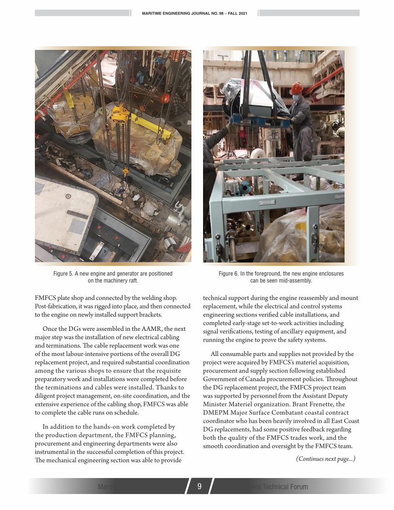
Following delivery of the new generator sets to FMFCS, the internal combustion engine shop meticulously disassembled them just enough for rigging and eventual installation on board (Figures 3, 4 and 5). Once the AAMR was prepared, the shop rebuilt the new engines inside the space with assistance from the rigging shop and the mechanical engineering section. The sheet metal shop assembled the new acoustic enclosures (Figure 6), while the pipe fitters and welding shop installed the new NOVEC fire-suppression system.
Because the Caterpillar ACERT 32 engine has a different intake and exhaust configuration than the old MWM 602 engine, new engine intake and exhaust ducting had to be fabricated (Figure 7). To make this new ductwork, jigs were initially constructed in the AAMR to determine the distances and angles from the engine flange to the existing ducting that could be retained. Once the new pathway had been established, each segment of the new intake and exhaust ducting was fabricated by the
Figure 3a and b. A new Hitzinger generator is moved through the ship’s hangar, and lowered into the AAMR.
Figure 4. A new Caterpillar CAT ACERT32 engine, still in its protective wrap, is rigged into the AAMR. Note the tight clearances.
Maritime Engineering Journal 8 Canada’s Naval Technical Forum
MARITIME ENGINEERING JOURNAL NO. 98 – FALL 2021
Maritime Engineering Journal 9 Canada’s Naval Technical Forum
FMFCS plate shop and connected by the welding shop. Post-fabrication, it was rigged into place, and then connected to the engine on newly installed support brackets.
Once the DGs were assembled in the AAMR, the next major step was the installation of new electrical cabling and terminations. The cable replacement work was one of the most labour-intensive portions of the overall DG replacement project, and required substantial coordination among the various shops to ensure that the requisite preparatory work and installations were completed before the terminations and cables were installed. Thanks to diligent project management, on-site coordination, and the extensive experience of the cabling shop, FMFCS was able to complete the cable runs on schedule.
In addition to the hands-on work completed by the production department, the FMFCS planning, procurement and engineering departments were also instrumental in the successful completion of this project. The mechanical engineering section was able to provide
technical support during the engine reassembly and mount replacement, while the electrical and control systems engineering sections verified cable installations, and completed early-stage set-to-work activities including signal verifications, testing of ancillary equipment, and running the engine to prove the safety systems.
All consumable parts and supplies not provided by the project were acquired by FMFCS’s materiel acquisition, procurement and supply section following established Government of Canada procurement policies. Throughout the DG replacement project, the FMFCS project team was supported by personnel from the Assistant Deputy Minister Materiel organization. Brant Frenette, the DMEPM Major Surface Combatant coastal contract coordinator who has been heavily involved in all East Coast DG replacements, had some positive feedback regarding both the quality of the FMFCS trades work, and the smooth coordination and oversight by the FMFCS team.
Figure 5. A new engine and generator are positioned on the machinery raft.
Figure 6. In the foreground, the new engine enclosures can be seen mid-assembly.
(Continues next page...)

MARITIME ENGINEERING JOURNAL NO. 98 – FALL 2021
Maritime Engineering Journal 10 Canada’s Naval Technical Forum
Figure 7. A portion of the new engine intake and exhaust fabricated by Fleet Maintenance Facility Cape Scott.
By the end of March 2021, FMFCS had completed the majority of production work required to replace the two diesel-generators in Ville de Québec’s AAMR, and care and custody of the ship was transferred to Irving Shipbuilding for the remainder of the DWP. During the short transit to the Irving yard, one of the new DGs was used to supply
power to ship’s services, even though at the time the ship had two different versions of the integrated platform management control system installed on board. The set-to-work and other commissioning trials will be conducted once the two DGs in the forward auxiliary machinery room have been installed by ISI.
Although some work remains to be done before the ship is returned to the RCN, by the time this article was being drafted, FMFCS had invested some 10,000 person-hours in preparatory and production work on Ville de Québec’s AAMR DG replacement. The total cost for this was approximately $1.35 Million, which is less than the Government of Canada has historically paid to commercial shipyards to reach the same stage of work.
Beyond the financial considerations, this project has been a great opportunity for FMFCS to gain further experience with the new diesel-generators, while simultaneously demonstrating the shipyard’s important strategic capabilities to the RCN. The teamwork and dedication demonstrated by all personnel involved in the AAMR DG replacement has been commendable, while the experience gained during this project will be incredibly useful moving forward, if and when FMFCS is required to complete major DG repairs in a deployed setting.
Over the course of the project, FMFCS has proven that it has the experience and technical skillsets required to successfully complete major engineering changes that have traditionally been contracted to non-DND shipyards. This capability will undoubtedly improve the operational effectiveness of the RCN in the years to come.
Lt(N) M.E. McKenna is the Deputy Marine Systems Engineering Officer at FMF Cape Scott in Halifax, NS.
Submissions to the Journal
The Journal welcomes unclassified submissions in English or French. To avoid duplication of effort and ensure suitability of subject matter,
contributors are asked to first contact the production editor at [email protected].

MARITIME ENGINEERING JOURNAL NO. 98 – FALL 2021
Maritime Engineering Journal 11 Canada’s Naval Technical ForumMaritime Engineering Journal 11 Canada’s Naval Technical Forum
By Stephen Harrison, Flavio Stasi and LCdr Yohan Desjardins
I n the last article from the CSC Project Management Office (PMO) in MEJ 96, we discussed training, and the challenges the training system is facing with
the introduction of the RCN’s future fleet of Canadian Surface Combatant (CSC) ships. Delivery of the first CSC is currently scheduled for the early 2030s, with a tests & trials program starting well before that. The high level of integration and complexity of the Canadian Surface Combatant combat suite, and the sophistication of its associated systems, will bring numerous challenges with it. This article will discuss how PMO CSC and the RCN plan on mitigating the risk of integrating some of the most technologically advanced naval warfare systems in the world through the use of a Land Based Test Capability (LBTC), consisting of a facility on Department of National Defence (DND) property near Shearwater, NS, and the facility’s hardware-software payload and test environment.
BackgroundOne of the primary functions of a warship as an integrated weapons platform is the detect-to-engagement sequence (DTES). This sequence includes searching, detecting, identifying, designating, acquiring, tracking, evaluating, assigning weapons, and engaging targets, and can evolve with or without operator input. Target information is processed and shared between the various elements of the naval combat systems, including the display consoles, whereupon operator interaction with the naval combat systems is initiated.
The speed and accuracy at which this process occurs is in direct correlation to the operational effectiveness of the integrated naval combat systems in the ship. However, without proper systems integration and operator training, there is a risk that the integrated naval combat systems could also demonstrate behaviours causing hostile targets to be misrepresented within the system, or causing operators to misunderstand the information presented to them, thereby resulting in a reduction of operational effectiveness. This could result in delays to the DTES or, in the most extreme cases, in the
A Land Based Test Capability for the Canadian Surface Combatant Project
FEATURE ARTICLE
engagement of friendly forces or civilian entities. Although complex weaponized military systems such as CSC are invaluable to the defence of Canada, and are a key part of the Strong , Secure and Engaged Defence Policy, if the behaviour of the naval combat systems is not fully understood prior to entering operational service, then there is a possibility for disastrous events to occur.
Complexity of the ShipThe CSC’s combat systems will be comprised of many hardware, software, and operator-machine interface elements associated with anti-submarine warfare (ASW), anti-surface warfare (ASuW) and anti-air warfare (AAW) domains. Each individual piece of equipment, including both its hardware and software, must be qualified by the original equipment manufacturer (OEM) to show that it will meet the required specifications. Typically, these required specifications are demonstrated during a factory acceptance test (FAT). Once qualified at the equipment level, the equipment will then be integrated within the ship’s naval combat system. This system-level integration typically occurs in a laboratory setting many months, if not years, in advance of the actual ship construction, and will be done using emulated or simulated external inputs. However, the final integration work requires that, as much as possible, elements be integrated and exposed to real-world conditions, with some inputs understandably coming from emulation, simulation or stimulation, depending on the system and options available for the testing.
The level of complexity of the equipment increases risk within the process. Some of these risks include:
• a single piece of equipment not meeting the manufacturer’s stated specification;
• individual subsystems not being integrated effectively, or integrated with errors induced by the passing of erroneous data between subsystem elements; and
• individual systems not being able to perform their roles within the overall naval combat system.
(Continues next page...)

MARITIME ENGINEERING JOURNAL NO. 98 – FALL 2021
Maritime Engineering Journal 12 Canada’s Naval Technical Forum
Requirement for a Land Based Test CapabilitySince a single error within this process could affect a system’s operational employment, and possibly impact the entire naval combat system, the best way to reduce this risk is to conduct a robust and thorough testing program on the fully constructed naval combat system. However, conducting such a program on board the lead warship at sea is not necessarily the best option. The two to four years spent in testing effectively reduces the overall operational hull life of the ship by that same amount, and the test program is subject to external factors such as weather, equipment failures, and the availability of supporting units that can result in schedule delays, or even cancellation of the program itself. The construction of an LBTC facility was therefore determined to be the best mechanism for reducing the integration risks by enabling much of the integration activities ashore, and being able to re-run tests as required without the need for sending a CSC platform to sea. As the official statement on this makes clear, there is an overarching aim in which:
“The purpose of the LBTC is to mitigate the risk to the CSC platforms by providing a shore-based capability to conduct system analysis, support the CSC system through-life, support CSC assurance assertions, and conduct verification and validation.”
The Land Based Test Capability is therefore a key component of the CSC program’s integrated test, evaluation, and acceptance strategy for allowing incremental and evolutionary development, verification, and validation of CSC systems. The LBTC facility will host an environment in which a suite of validated, high-fidelity simulation, stimulation and analysis tools is able to accommodate a mix of real, emulated, and simulated system inputs for testing and analyzing new and emergent features of CSC systems and subsystems before they are taken to sea.
To assist in defining requirements for the LBTC, the PMO conducted a review of several allies’ ship construction projects to ascertain whether there was a global benchmark for a testing facility. The results of the survey showed that the USA, UK and Australia all have land-based test facilities employed to reduce risk in their ship construction projects. The USA has several facilities comprised of the Surface Combatant Systems Center located at Wallop’s Island, Virginia, and the Combat System Engineering Development Site in Moorestown, New Jersey. The UK utilizes the Maritime Integration & Support Centre (MISC), which is similar to what Canada is
looking for in terms of our own LBTC. Australia is in the process of building a land-based test facility at St Kilda Transmitting Station, Australia north of Adelaide in support of the Royal Australian Navy (RAN) Hunter-class warship.
The requirement for land-based testing capability of integrated systems is nothing new, but it does require tailoring to the type of equipment being installed in a ship. The PMO is therefore actively engaged with its partners to learn from their experience as we develop our own LBTC project.
What will the CSC’s Land Based Test Capability look like?The LBTC is composed of three key elements: The facility, which provides the physical infrastructure to house, operate and test CSC systems; the payload, which includes the CSC combat system shipset, synthetic ship, and other specialized tools; and, the test environment, which provides the computational infrastructure to host the synthetic ship and a wide range of software tools to manage scenarios, and stimulate and measure various configurations of CSC systems. These elements will interact with a broad range of national and international facilities as well as real-world assets to support the test and evaluation needs of the CSC Project.
The first step in building a facility was to find a suitable location that met all requirements. The CSC Project requires the ability to perform operational testing at the system and subsystem level, thus mandating the operation of emitters and sensors at the various power levels and frequencies used in operational scenarios in a representative maritime environment. This resulted in studying several locations that could be suitable for radiating emitters over the ocean. Ideally, the proposed building location would have the emitters installed at a ship-appropriate height above the

MARITIME ENGINEERING JOURNAL NO. 98 – FALL 2021
Maritime Engineering Journal 13 Canada’s Naval Technical Forum
waterline to provide the most realistic testing available. There were several DND-owned locations considered during the rigorous site selection process, and after a thorough review the site selected for the future LBTC is located at Hartlen Point, Eastern Passage, NS.
The Hartlen Point facility will house the test environment and most of the CSC’s combat system suite, along with its associated systems and subsystems. The building will provide services such as power, cooling, and HVAC; workspaces for personnel; and, infrastructure that will enable the operation and management of the systems and equipment contained therein. The shore-based location, combined with the topside infrastructure to support sensors and emitters, will allow the Navy to execute testing and evaluation of CSC systems using a representative operational environment with real assets.
The payload is a representation of the CSC systems, subsystems, and equipment, and includes the test sets, specialized tools, and synthetic ship required to test these integrated systems. CSC sensors and emitters will be arranged on the facility’s topside infrastructure to closely match the planned shipboard superstructure arrangement, including height above the waterline within an acceptable tolerance. Systems that have constraints on cable lengths will be replicated faithfully through proper arrangement of internal systems. Although facility restrictions will preclude the live operation of certain sensors such as navigation radars, “critical input” from these sensors will be synthetically generated by the test environment and injected into the appropriate CSC systems.
The test environment refers to the integrated systems and software that will enable test development, stimulation and measurement of the system under test, configuration management, scenario generation and management, problem investigation and root cause analysis, and analysis of results. Through these tools, CSC system inputs/outputs will be controlled and measured respectively. Automated repeatable tests with defined and controlled scenarios will be executed, which will enable early detection, investigation and resolution of integration, operation, and interoperability issues. The test environment will enable the injection of simple messages up to complex synthetic tracks into CSC systems. To enable more realistic testing of the CSC system over a broad range of potential operational conditions, this functionality will extend to representative operational testing using live emitters able to radiate at full power, interacting with real-world assets blended with simulated entities and targets.
ConclusionIn the last few years, PMO CSC has identified the need of a Land Based Test Capability to assist with ship delivery. A small team within the PMO, with assistance from Assistant Deputy Minister (Infrastructure & Environment), Irving Shipbuilding Inc., Defence Construction Canada, and the selected design agent, will have the task of identifying requirements, designing and building the infrastructure, and completing systems installation in advance of CSC Ship 1 tests & trials.
The timeline for the LBTC facility is aggressive, with construction planned to start in the summer of 2022, and target delivery in summer 2025. This is no small undertaking, as there is a lot of work ahead, most notably with the design and construction of the facility, and with the integration of the combat systems in support of tests & trials evaluation requirements. However, the infrastructure project is currently on track, and received funding approval in March of this year (2021).
The Canadian Surface Combatant Project to modernize warfighting capability in the RCN is Canada’s most complex major capital project to date. Its success depends heavily on the availability of an equally modern and advanced Land Based Test Capability to ensure the full integration of the CSC’s sophisticated combat suite, an effort that will require the continued collaborative effort of all stakeholders.
AcknowledgmentThe assistance of Jennifer Spearman (PMO CSC in Halifax) in the preparation of this article is gratefully acknowledged.
Stephen Harrison is the Deputy Project Manager (Transition) Land Based Test Capability Lead for the Canadian Surface Combatant Project Management Office in Ottawa.
Flavio Stasi is the Land Based Test Capability Systems Engineer for the Canadian Surface Combatant Project Management Office in Halifax.
LCdr Yohan Desjardins is the Infrastructure Manager for the Canadian Surface Combatant Project Management Office in Ottawa.

MARITIME ENGINEERING JOURNAL NO. 98 – FALL 2021
Maritime Engineering Journal 14 Canada’s Naval Technical Forum
Titles of Interest
The story follows young Wally as he leaves the family farm on the prairies to pursue
a daring career in the navy—leaving love interest Winnie behind. It is a high-stakes adventure, a love story, and an important historical lesson for readers of all ages. This striking Canadian graphic novel features meticulously detailed black and white drawings, an illustrated diagram of HMCS Sackville, information on wartime propaganda, a glossary, and an illustrated map.
For more information on this uniquely Canadian story, go to: Canadian Naval Memorial Trust, Spring 2021 issue of Action Stations! https://hmcssackville.ca/resources/action-stations/
On 16 March 1807, the British Parliament passed The Abolition of the Slave Trade Act. In the following year the Royal Navy's African
Squadron was formed, its mission to stop and search ships at sea suspected of carrying slaves from Africa to the Americas and the Middle East. With typical thoroughness, the Royal Navy went further, and took the fight to the enemy, sailing boldly up uncharted rivers and creeks to attack the barracoons where the slaves were assembled for shipment.
For much of its long campaign against the evil of slavery, Britain's Navy fought alone and unrecognized. Its enemies were many and formidable. Ranged against it were the African chiefs, who sold their own people into slavery, the Arabs who rode shotgun on the slave caravans to the coast, and the slave ships of the rest of the world, heavily armed, and prepared to do battle to protect their right to traffic in the forbidden black ivory. The war was long and bitter, and the cost to the Royal Navy in ships and men heavy, but the result was worthy of the sacrifices made.
The abolition of the slave trade led to a scramble for empires and, in place of slaves, Africa began to export cocoa, coffee, timber, palm oil, cotton and ores, all very much in demand in the West.
BOOKS
A middle-grade graphic novel exploring the Battle of the Atlantic from a young prairie boy’s perspective.
Story by Brian Bowman; Art by Richard Rudnicki, with Susan Tooke
ISBN: 9781771087582; Nimbus Publishing (2021)
https://nimbus.ca/store/dusty-dreams-and-troubled-waters.html
By Bernard Edwards
208 pages; Black and white photos
ISBN: 9781399013505; Pen & Sword Maritime (2021)
https://www.pen-and-sword.co.uk/Royal-Navy-Versus-the-Slave-Traders-Enforcing-Abolition-at-Sea-1808-1898-Paperback/p/19084
Dusty Dreams and Troubled Waters: A Story of HMCS Sackville and the Battle of the Atlantic
Royal Navy Versus the Slave Traders: Enforcing Abolition at Sea 1808-1898

MARITIME ENGINEERING JOURNAL NO. 98 – FALL 2021
Maritime Engineering Journal 15 Canada’s Naval Technical Forum
Titles of Interest
This updated and expanded edition of Cyberspace in Peace and War by Martin C.
Libicki presents a comprehensive understanding of cybersecurity, cyberwar, and cyber-terrorism. From basic concepts to advanced principles, Libicki examines the sources and consequences of system compromises, addresses strategic aspects of cyberwar, and defines cybersecurity in the context of military operations while highlighting unique aspects of the digital battleground and strategic uses of cyberwar.
This new edition provides updated analysis on cyberespionage, including the enigmatic behaviour of Russian actors, making this volume a timely and necessary addition to the cyber-practitioner's library. Cyberspace in Peace and War guides readers through the complexities of cybersecurity and cyberwar and challenges them to understand the topics in new ways. Libicki provides the technical and geopolitical foundations of cyberwar necessary to understand the policies, operations, and strategies required for safeguarding an increasingly online infrastructure.
The Royal Navy’s greatest contribution to the Allied success in World War II was undoubtedly the defeat of the U-boat menace
in the North Atlantic, so it was not surprising that captured German submarine technology became the focus of attention for the British submarine service after 1945. However, the same technology had also fallen into the hands of the Soviet Union, and as the Cold War developed it became clear that a growing Russian submarine fleet would pose a new threat.
While Britain had to go to the US for its first nuclear propulsion technology, the Royal Navy introduced the silencing technique which made British and US nuclear submarines viable anti-submarine assets. Although some of the Cold War activities of British submarines have come to light in recent years, this book will be the first comprehensive technical history of the submarines themselves, their design rationale, and the service that operated them.
By Martin C. Libicki
512 pages; Illustrations
ISBN-10: 1682475867 US Naval Institute Press (2021)
https://www.usni.org/press/books/cyberspace-peace-and-war-second-edition
By Norman Friedman
344 pages; 350 colour and black & white illustrations
ISBN: 9781526771223; Seaforth Publishing (2021)
https://www.pen-and-sword.co.uk/British-Submarines-Hardback/p/18002
Cyberspace in Peace and War, 2nd Ed.British Submarines in the Cold War Era
Let us know if you come across new titles
of interest!
MARITIME ENGINEERING JOURNAL NO. 98 – FALL 2021
Maritime Engineering Journal 16 Canada’s Naval Technical Forum
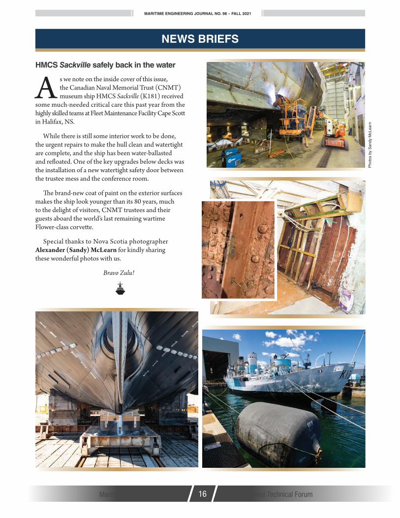
A s we note on the inside cover of this issue, the Canadian Naval Memorial Trust (CNMT) museum ship HMCS Sackville (K181) received
some much-needed critical care this past year from the highly skilled teams at Fleet Maintenance Facility Cape Scott in Halifax, NS.
While there is still some interior work to be done, the urgent repairs to make the hull clean and watertight are complete, and the ship has been water-ballasted and refloated. One of the key upgrades below decks was the installation of a new watertight safety door between the trustee mess and the conference room.
The brand-new coat of paint on the exterior surfaces makes the ship look younger than its 80 years, much to the delight of visitors, CNMT trustees and their guests aboard the world’s last remaining wartime Flower-class corvette.
Special thanks to Nova Scotia photographer Alexander (Sandy) McLearn for kindly sharing these wonderful photos with us.
Bravo Zulu!
NEWS BRIEFS
HMCS Sackville safely back in the water
Pho
tos
by S
andy
McL
earn

MARITIME ENGINEERING JOURNAL NO. 98 – FALL 2021
Maritime Engineering Journal 17 Canada’s Naval Technical Forum
NEWS BRIEFS
HMCS Fredericton Hull Insert Repair — A Team EffortBy Greg Stymest, FMF Cape Scott
I magine having to cut a hole in the side of a frigate large enough to drive a half-ton truck through, and that is exactly what Fleet Maintenance Facility Cape
Scott (FMFCS) did last spring with HMCS Fredericton (FFH-337). In February 2021, ahead of the ship’s July 24 deployment as flagship of Standing NATO Maritime Group 1 (SNMG1), a general inspection by Maritime Forces Atlantic (MARLANT) hull inspectors revealed holes in some of the ship’s longitudinals, prompting a closer look at the condition of the hull and shell plating.
The thickness of new plating and hull material is 10 mm, so when non-destructive testing (NDT) showed thickness readings as low as 6.25 mm on the shell plating and hull, 3.75 mm on the longitudinals, and 3.43 mm on the frames along a 6m x 3m section on the ship’s port side, it was clear something had to be done. Following discussions with the MARLANT Fleet Technical Authority, Engineering Division, Operations Division, and the FMFCS Production Manager and General Manager, a decision was made by the Commander of Canadian Fleet Atlantic (CCFL) to proceed with a hull-insert repair on Fredericton.
FMFCS was faced with the challenging task of getting the ship out of the water, constructing a temporary weather enclosure around the work area on the outdoor Syncrolift, cutting away the defective material, and installing a new insert within an extremely tight timeline to meet tide and operational considerations. The unit would have just 29 days to complete the repairs. Any longer, and the ship would be forced to stay on the Syncrolift until the next high tide a month later.
To manage this, FMFCS asked some of the key trades involved to go on a 24-7 work cycle, and to have everyone available for support when called upon. Careful planning and scheduling ensured that all of the trades people involved would come together as a well-choreographed team. On February 28, with everything ready, the docking crew and other personnel worked against high winds and cold temperatures to successfully dock Fredericton on the Syncrolift at high tide. The clock was running.
As soon as the ship was docked, a protective enclosure designed by our engineering section was erected by the
RC
N p
hoto
(Continues next page...)

MARITIME ENGINEERING JOURNAL NO. 98 – FALL 2021
Maritime Engineering Journal 18 Canada’s Naval Technical Forum
NEWS BRIEFS
shipwright shop. As winter weather was upon us, having this in place would be crucial to the success of this project. The enclosure was fabricated using staging and supports, covered by a watertight membrane sealed against the side of the ship to keep the work area dry and clean (Figure 1). With portable heaters running 24-7, workers were able to progress the repairs throughout the cold nights, including allowing paint to be applied and dry.
The first hurdle was to finish removing the many interference items inside the ship that were blocking full access to the frames, longitudinals and hull plating (Figures 2a and 2b). Some of the clear-away work had been done while the ship was still alongside its berth, but the list of items was a long one. The complete chiller unit was removed, including its associated piping and the large steel platform that supports it. Also removed were the no. 2 auxiliary seawater circulation pump, LP air system, integrated platform management system (IPMS), several cables and wireways, lighting, gauge panels, ventilation, controllers, air lines, overboard discharge lines and various valves. Furthermore, prior to burning out the existing steel insert and frames, the paint coatings had to be scaled with a needle gun to bring the steel to a bare metal state.
The preparation work was intense, and this is when several of the unit’s support trades came into the plan and stepped up to assist with this huge task. With ongoing repairs still being made to the ship’s fuel-oil transfer and hydraulic start systems, it made for a very congested work
area, but the teams persevered. One of the many obstacles they faced was the removal of the bilge keel, which had to be drained of fluid, cut out into sections and repaired. There were many unknowns, as the unit had never done this type of work before, but with the support of our engineering, hull production and safety people, the fluid was removed safely. Once the interference items were removed it was time to cut a hole in the side of the ship.
Burners and platers cut an 18-m2 rectangular opening (Figure 3) that went from the after engine room (AER) to just inside the forward engine room (FER), including a portion of the watertight bulkhead. The removals also included 14 frames and longitudinals that had to be templated and remanufactured by the plate shop (Figure 4) prior to being fitted and welded into place on board. Everything was properly X-rayed and inspected. With the clock ticking down, there were several essential items that had to be reinstalled prior to undocking, including the overboard discharge system, and any bracing or supports welded to the exterior hull that were below the waterline. The hull plates and bilge keel also required several coats of primer and paint to meet the mil thickness required. Without the heated enclosure, this would not have been possible.
The most challenging part of the job was the removal of the bilge keel and the fluid inside the keel, and then templating and scribing the proper mitre to reconnect the
Rep
air
phot
os c
ourt
esy
FM
F C
ape
Sco
tt
Figure 1. Scaffolding set up inside the weather enclosure, with the ship’s side plating and section of angled bilge keel removed.
Figures 2a & 2b. The first hurdle was to finish removing the many interference items inside the ship that were blocking full access to
the frames, longitudinals and hull plating.

MARITIME ENGINEERING JOURNAL NO. 98 – FALL 2021
Maritime Engineering Journal 19 Canada’s Naval Technical Forum
bilge keel onto the new steel insert (Figure 5). After 29 working days, and with no room for error, the ship was undocked on the final day of high tide on the evening of March 31. It was an unbelievable accomplishment, especially since the project had not been without certain challenges beyond our control. There were several weather issues and many unexpected power outages, and even when the city of Halifax was blanketed by a major snowstorm and shut down for the day, the crew still came to work to ensure the repairs continued.
All told, some 6800 hours of skilled work was by performed by more than 100 personnel from the FMF Cape Scott trade shops, engineering and technical staffs, civilian contractors, and HMCS Fredericton and other naval staffs. The technical
Figure 3. The 18-m2 rectangular opening went from the after engine room (AER) to just inside the forward engine room (FER).
Figure 4. Fourteen frames and longitudinals had to be templated and remanufactured by the plate shop prior to being fitted
and welded into place.
Figure 5. The removed section of bilge keel (missing in this image) had to be templated and scribed with the proper mitre before
reconnecting it to the new steel insert.
requirements set a new bar for what FMFCS is capable of doing on short notice, but the most rewarding part of the job was being able to meet the timelines of the repairs so that the ship would be ready to deploy on time.
NEWS BRIEFS

MARITIME ENGINEERING JOURNAL NO. 98 – FALL 2021
Maritime Engineering Journal 20 Canada’s Naval Technical Forum
NEWS BRIEFS
FMF Cape Breton docks USN submarine camelsBy Brian McCullough, MEJ Production Editor
with files from Lt(N) Peter Summers and Ashley Evans, FMF Cape Breton
I t’s not something the general public would normally expect to see—two American camels sitting on wooden blocks in a drydock. And yet, even to those
familiar with the goings-on inside a naval dockyard, it was still something of an unusual sight.
The camels in this case refer to floating fender barges (Figure 1) used for berthing visiting U.S. Navy (USN) submarines at the Royal Canadian Navy (RCN) dockyard in Esquimalt, BC. The two barges have just completed a successful two-part docking work period for cleaning and repair by Fleet Maintenance Facility Cape Breton (FMFCB), and were undocked and returned to the Queen’s Harbour Master for service on Aug. 31.
Ship camels are a Dutch invention from the 17th century. Essentially pontoon barges, they were designed to be strapped to the sides of ships of the line, and then unballasted to lift the warships across the sandbars blocking access to the open sea. The term “camel” likely stems from their original purpose as carriers, in the sense the barges acted as beasts of burden.
The USN submarine camel barges are ballastable structures that consist of a bollared deck platform, with a massive steel undercarriage that hangs down about six metres below the waterline. The underwater structure has horizontal rubber fenders fixed to one side that press against the support columns of a pier or jetty, while the other side has vertical rubber fenders to protect a submarine’s hull when it is berthed alongside. The whole purpose is to keep a low-profile submarine from connecting directly against the columns of jetties designed for surface ships, and to also protect the jetty structure.
What made the docking operation a bit out of the ordinary is that FMFCB had no drawings from which to produce the necessary docking plan—the camels are on long-term loan to Maritime Forces Pacific from the USN—and hardly anyone had ever seen one of them out of the water before. When a convenient docking opportunity opened up last year (2020), the FMF teams would have to once again demonstrate their proven ability to quickly assess a challenging situation, and create a safe docking and
work plan in short order. It’s all part of their role as strategic RCN assets in providing agile materiel support to the fleet.
FMF Docking PlanThe docking plan is a drawing that shows the dock blocks a vessel sits on within the drydock. The FMF Naval Architecture section is responsible for producing all docking procedures and specifications, as well as providing oversight for docking evolutions. Four people from Nav Arch were involved in the docking planning process: the docking officer and assistant docking officer who developed all of the plans; a structural engineer who assisted with analyzing the strength of the camel barges and the suitability of various block layouts; and an engineering design technologist who produced (and constantly updated) the drawings for the docking plan.
The docking officer works closely with the FMF dock master and project leader to plan the docking evolution, and to coordinate the required support. This includes determining where the vessels will be located inside the dock and how they will be supported, along with tug support, diver support, production support, environmental and safety considerations, and other stakeholder considerations.
Figure 1. These two U.S. Navy submarine camel fender barges, on semi-permanent loan to the RCN, were completely refurbished and returned to service by Fleet Maintenance Facility Cape Breton
in Esquimalt, BC.
Pho
tos
cour
tesy
FM
F C
ape
Bre
ton

MARITIME ENGINEERING JOURNAL NO. 98 – FALL 2021
Maritime Engineering Journal 21 Canada’s Naval Technical Forum
NEWS BRIEFS
All docking plans begin with a set of calculations that check a variety of factors such as adequate block arrangements to allow the vessel to land and come to rest on the blocks without damage to the keel, support the vessel’s weight, prevent the vessel from overturning due to high winds or earthquake, and assurance that the vessel will remain stable once the water is removed from the dock. Accurate vessel drawings are obviously a key element in these calculations, but since no official drawings of the camels were available, a dive survey was requested to verify the design and condition of their underwater structure. Low dive visibility in Esquimalt Harbour, the positioning of the camels alongside a jetty, and the extent of marine growth on the structures (Figure 2) made it difficult at first to properly assess them, so it took a number of dives by Fleet Diving Unit Pacific (FDUP) divers and a civilian contract diver with a live video/communication capability to produce reasonably accurate drawings.
Due to a compressed schedule for drydock availability, a number of the dock blocks had already been placed on the drydock floor by the time the drawings and an updated docking plan based on the dive survey were produced. Some of these blocks subsequently had to be repositioned, in part because the divers discovered that two of the 10 legs on one of the camels were extremely bent, and would not support the barge in the drydock. It is unclear how the legs, which are made of large steel I-beams, got damaged, but Nav Arch staff had to rejig the docking plan to ensure the camel was properly supported, and included extra blocks in case the bent legs knocked any block stacks out of kilter as the camel was being floated into position.
The Work EffortRoughly 6100 person-hours of work went into overhauling each of the two camel barges to conduct the surveys, clean off the marine growth, replace the damaged legs, and repair
the corroded bollards, decking and sides of tanks. All surfaces were blasted and repainted, and a full set of anodes was replaced or added to each fender barge. While in the dock, the camels were placed in separate shelters to facilitate concurrent work activities by the various shops, minimize noise, and prevent contaminants from sandblasting inside one shelter affecting painting going on inside the other.
Before entering the dock last year (2020), the surveys performed on the camels by the divers had been hampered by the extent of the marine growth on the underwater surfaces, which made it hard to assess the true state of their condition. The full scope of repairs required wouldn’t be known until after the structures had been cleaned to bare metal, when it was discovered that there was far more repair work required than initially thought. Due to a limited
Figure 2. The substantial marine growth and murky conditions during the underwater survey hid the extent of work that would be required to fully repair the camels. In the end, the full cleaning and repair job
had to be conducted across two separate docking windows.
(Continues next page...)

MARITIME ENGINEERING JOURNAL NO. 98 – FALL 2021
Maritime Engineering Journal 22 Canada’s Naval Technical Forum
NEWS BRIEFS
docking timeframe, only a portion of this could be progressed before the FMF had to prep the camel fenders to go back into the water to make way for other previously scheduled jobs in the drydock.
The second docking period, which began in May 2021, allowed enough time to continue on with the repairs and finish off the work within the prescribed time. Once completed, the beautifully refurbished camels were placed in the charge of the Queen’s Harbour Master (Figure 3) for removal from the drydock and storage, ready for the next visit by a USN submarine.
From the initial assessments and docking plan calculations, to the dive surveys and the two docking repair phases, the FMF Cape Breton teams and their partner units demonstrated the exceptional capability that exists within the RCN to marshall an effective full-team effort under less-than-perfect circumstances.
Lt(N) Peter Summers is the former Deputy Naval Architecture Officer at FMF Cape Breton. Ashley Evans is the Strategic Communications Officer for the FMFs on both coasts, and is based in Esquimalt.
Figure 3. The Esquimalt Harbour tug CFAV Tillicum (YTM-555) prepares to pull the second of two USN submarine camel fender barges out of FMF drydock for return to service at the end of the
second docking work period on Aug. 31. In the background is a large YOM-250 environmental barge that was docked with the camels.
Your Navy Today – Featured Video
Future joint support ship HMCS Protecteur’s bulbous bow in place.
https://www.facebook.com/RoyalCanadianNavy/
videos/171464794956284/

Maritime Engineering Journal 23 Canada’s Naval Technical Forum
A Few Experiences of a Young Lieutenant(N) Naval Architect
A-bracket corrosion:
In 1962, I was tasked with visiting Davie Shipbuilding in Lauzon, QC to investigate a St. Laurent-class destroyer that was exhibiting severe corrosion pockmarks on the A-brackets that support the propulsion shafts just forward of the propellers. Both arms of the port and starboard brackets were pockmarked on one side only, in mirror image to one another, indicating that the ship’s wake must be striking the bracket arms at an angle such that the water flow was smooth on one side, and turbulent with cavitation on the other.
Back in Ottawa, I looked up the ship-class towing tank report from the National Research Council, and noted that the recommended fore and aft angles for the A-brackets were based on the wake flow at the ship’s top speed of about 28 knots. What was happening was that, with the ship travelling at a speed of just 12-15 knots most of the time, the brackets were misaligned with the flow of the wake, causing the one-sided turbulent flow and cavitation. In other words, the ship’s waterflow noise would be worst at the speed it would be conducting most of its anti-submarine operations. Ten years later when I was working on the DDH-280 Tribal Class project, I made sure that the A-bracket orientation was optimized for speeds of 12-15 knots.
HMCS Provider inclining experiment:
When the replenishment oiler HMCS Provider (AOR-508) was inclined at Davie Shipbuilding, Lauzon, QC in 1963 to calculate the tanker’s
CNTHA News Est. 1997
CNTHA ChairmanPat Barnhouse
CNTHA Executive DirectorTony Thatcher
Directorate of History and Heritage LiaisonMichael Whitby
Maritime Engineering Journal Liaison
Brian McCullough
Webmaster Peter MacGillivray
Webmaster Emeritus Don Wilson
CNTHA News is the unofficial newsletter of the Canadian Naval
Technical History Association. Please address all correspondence
to the publisher, attention Michael Whitby, Chief of the
Naval Team, Directorate of History and Heritage, NDHQ
101 Colonel By Dr Ottawa, ON K1A 0K2 Tel. (613) 998-7045 Fax (613) 990-8579
Views expressed are those of the writers and do not necessarily
reflect official DND opinion or policy. The editor reserves the right to
edit or reject any editorial material.
www.cntha.ca
Canadian Naval Technical History Association
News(fall 2021)
preserving canada’s naval technical heritage
stability and safe load capacity, Lt(N) Peter Bergen and I had to first inspect every space to estimate and record the weight of extraneous gear and any liquids remaining in all tanks. Then, as Davie used a crane to move large blocks of known mass from one side of the upper deck to the other, we took careful note of the angle of heel, the draught fore and aft, and other factors including water density. Since the tides affect the water level and currents in the St. Lawrence River at Lauzon, we consulted the tide tables to ensure the experiment would be conducted at slack water.
As the experiment got underway, and the weights were shifted in stages, we plotted the increasing heel of the ship on a graph. If I remember correctly, the first three moves plotted a nice straight line, but the fourth was a bit low, and the fifth came in even lower. By then it was late in the day, so we stopped the operation and told our Davie contact that we would check with HQ to see if we would have to redo anything. After calculating the metacentric height based on the first three readings, we were quite relieved when Capt(N) Keith Farrell, Director of Ship Design and Construction, said that the experiment was sufficient, and the result was acceptable. The consensus was that the river current had started to run before we had finished, thus skewing the numbers.
Maritime Engineering Journal 23 Canada’s Naval Technical Forum
CNTHACNTHA
By Commodore (Ret’d) W.J. Broughton
HMCS Provider
(Continues next page...)

MARITIME ENGINEERING JOURNAL NO. 98 – FALL 2021
Bow shape design study for hull-mounted sonars:
Also in 1963, I was tasked to visit both the Royal Navy (RN) and the United States Navy (USN) to learn their thoughts on where they intended to locate the hull-mounted sonars on their ships. The two options being considered by the RCN for our General Purpose (GP) Frigate project were a retractable keel-mounted fit, and a bulbous bow arrangement.
I began by visiting the UK National Physical Laboratory southwest of London to learn the results of a water flow study conducted with the test ship HMS Penelope (F127). The study, which considered the effect of different underwater bow shapes in delivering the smoothest (i.e. quietest) waterflow past a retractable sonar mounted abaft the start of the keel, showed that a parabolic shape for the bow’s stem would be best for the sonar and for seakeeping, and more cost-effective than going to a bulbous bow.
I then visited the David Taylor Model Basin near Washington, DC to see what the USN was leaning toward, and was surprised to learn that they preferred the bulbous bow option based on low noise, better seakeeping, and reduced resistance for propulsion—almost the same three factors looked at by the RN, but with the opposite conclusion! The GP Frigate was eventually cancelled, but two iterations later, the parabolic stem for the bow was used on the Canadian navy’s four DDH-280 Tribal-class destroyers.
Maritime Engineering Journal 24 Canada’s Naval Technical Forum
Simulated atomic blast:
In 1964, while still a junior lieutenant, I was understandably surprised and nervous when I was summoned to Engineering Commodore Sam Davis’s office. I needn’t have worried, as it was only to discuss a planned, simulated atomic air blast against the destroyer escort HMCS Fraser (DDE-233) off Hawaii as part of Operation Sailor Hat. Earlier, a similar test had been conducted with USN participation at a site near Suffield, AB, where various equipment and structures, including a Canadian mast, had been exposed to a 500-ton TNT blast. The commodore simply wanted me to calculate how close Fraser could be anchored to the blast so as to sustain no more than $20,000 in repair costs. I was to report back to him.
Fraser had been chosen for the trial because it was scheduled to go into refit at Vickers Ltd in Montreal. After calculating the possible above-deck structural damage, I estimated that the ship could lie as close as about 500 yards to the explosion, with the deckhead of the captain’s cabin being the weakest structure and most likely to suffer permanent deflection. This amused the commodore greatly. I only learned of the results of the trial the following year, after my posting to HMC Dockyard Halifax. Fraser, it seems, had been anchored twice as far from the blast as I had estimated, which was a good thing considering the amount of damage inflicted on various bits of topside equipment. As I had predicted, however, the deckhead of the CO’s cabin did suffer a permanent deflection.
Tribal-class bow design (HMCS Algonquin)