marine steam boilers - boiler construction history/marinesteamboilers... · 32 marine steam boilers...
TRANSCRIPT

MARINE STEAM BOILERS
precision than is possible in the ordinary Bessemer bottom-blown converter ; it is on that accoUnt more generally used where the output of the steel foundry is small and castings of specified quality are required. .
The charge of liquid pig-iron in the converter processes " boils " when blown, whether it be through the bottom or across the surface. During this agitation of the metal the silicon, manganese and carbon are oxidized, these elements being subsequently re-added in quantities to suit the finished requirements.
Open-hearth Proct;SS for Cast Steel
Oxidation in the case of the open-hearth processes is effected partly by oxygen supplied from excess air in the furnace gases, partly from oxides floating as slag on the charge surface, which have been formed during the melt, and partly from iron ore added
. to the charge. The generation of carbon monoxide during the removal of the
carbon causes the metal to "boil", and more ore is fed into the slag to maintain this " boil " until. the oxidation of the silicon and manganese is complete and the carbon content has reached the required proportion.
l-l 1· :~t· ~ t· ; CHAPTER 4
..,;. BOILER CONSTRUCTION
· JT would appear that riveted construction for boilers began in the early nineteenth century, and, according to early works on
the subject, wrought-iron riveted boilers constructed from plates only 3 ft. by 1 ft. were in use at that time, working at pressures up to qo lb.fsq. in. A present-day tendency is for electricallywelded seams to take the place of riveting, especially for the internal parts of tank-type boilers, where such parts are in compression.
In this chapter details of the construction of riveted, welded and forged boilers will be given, and also particulars of requirements and tests.
RIVETED CONSTRUCTION
The Scotch boiler is undoubtedly the most frequently · encountered boiler of the riveted type. In the past they were used in the majority of cargo vessels in conjunction with steam reciprocating machinery for main propulsion purposes, whereas nowadays with the increased popularity of oil engines, their principal role is that of donkey boiler in large tankers. In present-day -::onstruction the use of welded seams for combustion chambers and the attachment of furnaces to these chambers has become almost universal, riveting being confined to the shell seams. In order that production of these boilers may proceed smoothly in the shop, it is essential that a definite routine be practised, so that no one part of the whole is held up while production of another is in progress.
The various stages from plate to finished unit will now be det11.i.l<id and briefly described.
First, the end plates, combustion-chamber tube, back" and wrapper plates are marked off and cut to required. dimensions. Work is then concentrated siinultaneously on the combustion chambers and the boiler end plates.
Combustion Chambers In the case of the chambers, the tube and back plates are flanged
in the hydraulic press, the flanging of the sides, bottom and ;t
32 MARINE STEAM BOILERS
top being effected prior to finishing with the corners. The plates are then levelled and, in the case of the tube plates, after pilot holes have been drilled for the tubes and centre of furnace, this opening is plunged.*
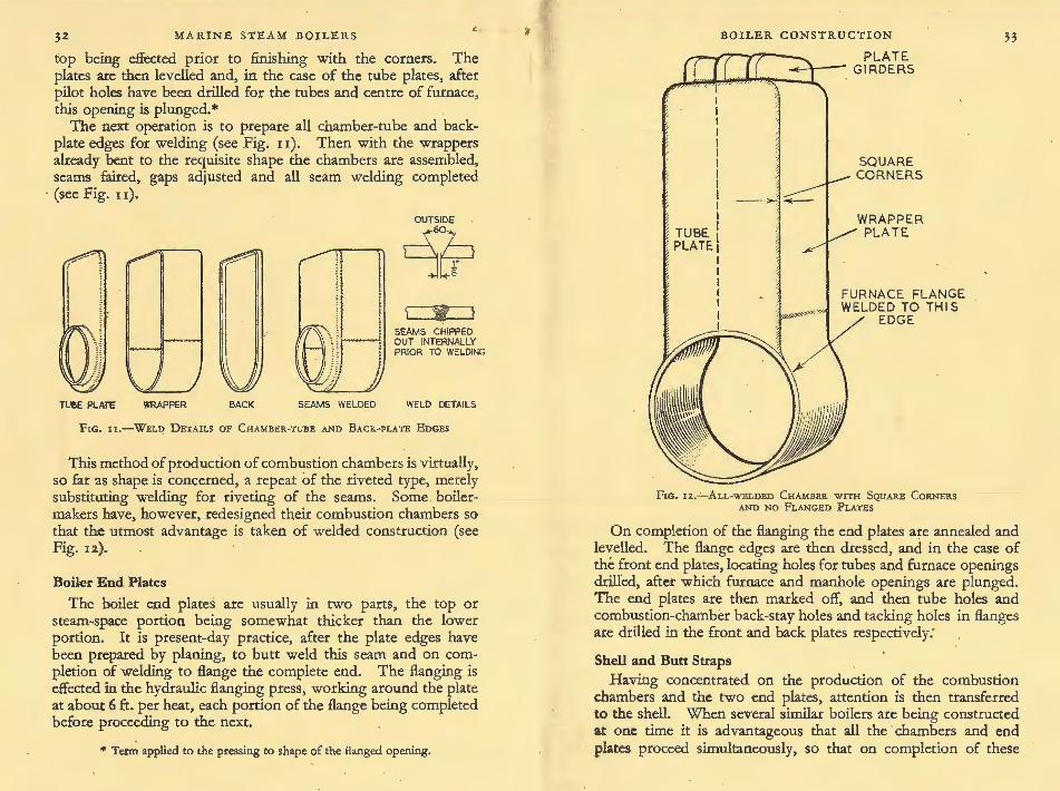
The next operation is to prepare all chamber-tube and backplate edges for welding (see Fig. II). Then with the wrappers already bent to the requisite shape the chambers are assembled, seams faired, gaps adjusted and all seam welding completed
· {see Fig. u).
I I
l TUB£ PlATE WRAPPER BACK SEAMS WELDED
OUTSIDE
9~ SEAMS CHIPPED OUT INTERNALLY PRIOR TO WELDiNG
WELD DETAILS
'FrG. n.-WELD DETAILS oF CHAMBER-TUBE AND BACK-PU.TE EDGES
This method of production of combustion chambers is virtually, so far as shape is concerned, a repeat of the riveted type, merely substituting welding for riveting of the seams. Some . boilermakers have, however, redesigned their combustion chambers so that the utmost advantage is taken of welded construction (see Fig. 12).
Boiler End Plates
The boiler end plates are usually in two parts, the top or steam-.space portion being somewhat thicker than the lower portion. It is present-day practice, after the plate edges have been prepared by planing, to butt weld this seam and on completion of welding to flange the complete end. The flanging is effected in the hydraulic flanging press, working around the plate at about 6ft- per heat, each portion of the flange being completed before proceeding to the next.
" Term applied to the pressing to shape of the flanged opening.
BOILER CONSTRUCTION
PLATE --+--- GIRDERS -""'-~~~-...&..
TUBE PLATE
SQUARE CORNERS
WRAPPER PLATE.
FIG. 12.-ALL-WBLDBD CHAMBER WITH SQUARE CoRNERS AND NO FLANGED PLATES
33
On completion of the flanging the end plates are annealed and levelled. The flange edges are then dressed, and in the case of the front end plates, locating holes for tubes and furnace openings drill'ed, after which furnace and manhole openings are plunged. The end plates are then marked off, and then tube holes and combustion-chamber back-stay holes and tacking holes in flanges are drilled in the front and back plates respectively:
Shell and Butt Straps Having concentrated on the production of the combustion
chambers and the two end plates, attention is then transferred to the shell. When several similar boilers are being constructed at one time it is advantageous that all the . chambers and end plates proceed simultaneously, so that on completion of these

34
(d)
MARINE STEAM BOILERS
(a)
FIG. 13.-AssEMBLY DuRING CoNSTRUCTION-SCOTCH BoiLERS
( >
BOILER CONSTRUCTION 35 components a certain amount of" pairing up " can be resorted to -a difference in circumference of more than ~ in. between front and back end plates is undesirable.
The shell plates are then marked off to suit the end-plate circumferences, all circumferential-seam rivet-holes are drilled and plate edges planed. Additionally, combustion-chamber sidestay; rolling-stay, lifting-lug and manhole-compensating ring holes are now drilled. -At this stage tacking holes only are drilled for the longitudinal butt-strap seams.
The shell plates are now rolled, and as the rolls do not impart correct curvature to the longitudinal edges, these have to be separately faired.
Attention is then directed to the butt straps, and these, after forming to the correct curvature, are, in the case of the outer strap, marked off and drilled ready for riveting, and, in the case of the inner strap, drilled with tacking holes only.
The shell and its butt straps are now assembled with tacking bolts, front and back end plates are fitted also with tacking bolts, and all seams are closed by means of the hydraulic riveting machine. In the case of the back end plate, this is done through a rectangular opening in this plate cut for the purpose and afterwards fitted with a han&-riveted cover plate. _ When all seams are closed, and all tacking bolts are hardened up, the " drilling through " of all rivet holes for the circumferential and longitudinal seams, and for the manhole ring, is effected.
T4e boiler shell is now taken apart and any burrs removed from around the drilled holes and plate edges.
With the inner butt straps fitted in place, the longitudinal seams are now faired up--and the 9 in. at the ends of each longitudinal seam are butt welded. On completion of this welding the outer butt straps are fitted in place and then the double-buttstrap longitudinal seams, as well as manhole-compensating ring, are hydraulically riveted.
Work is now concentrated on the front end plate. The furnace openings are bored out to take the furnaces, the circumferences of the bored openings being made about ·l2 in. larger than the furnace-mouth circumference. The bottom manhole Banging is also faced true at this stage.
Auembly Major assembly now begins. The front end plate is refitted
into the shell, and the front circumferential seam is hydraulically

MARINE STEAM BOILERS
riveted (Fig. 1 3 (a)). On completion of the riveting, all possible internal caulking is effected. .
The combustion chambers have meanwhile been drilled and reamered for plain tubes, after which each chamber top is fitted with its welded-on girder stays .. The chambers are then £airedup to their respective furnaces, and the circumferential furnaceto-chamber seams are welded, each assembly being annealed on completion of all welding. · The combustion chambers are next grouped together in their
correct positions, relative to one another, and all inter-chamber screwed stays fitted. On completion of this staying the group is placed on a pedestal with the furnaces vertical, and the shell with the front end plate is lowered over the group until the furnaces protrude sufficiently far through the end plate to allow ample room behind the chambers for work to proceed on the back-shell circumferential seam-(see Fig. 13 (b)). Temporary screwed stays are -fitted between the front end plate and the combustionchamber tube plates to hold the chamber group, and the back end plate is then fitted and hydraulically riveted, working through the cover-plate hole in the end plate (Fig. 13 (c)). Having completed the back · circumferential seam, the cover plate is fitted in position and riveted by hand.
-- All internal caulking of the shell seams is now effected. The group of combustion chambers is then lowered into its correct position and all furnace-mguth and combustion-chamber shell stay holes are drilled. The furnace-mouth seams ·are then hydraulically riveted and all combustion-chamber wing stays fitted (Fig. 13 (d)). .
The next operation is the drilling of all boiler back-stay holes; these holes are machine drilled, keeping the holes normal to the thinner of the two plates. While the boiler is on the machine, all stay-tube holes are then tapped and the stay tubes fitted.
Any surface depressions of the boiler back are now levelled out, either by strongbacks or by pulling on long bolts passed through the marginal stay holes, after which the combustionchamber back-stay holes are tapped and all stays fitted.
The plain tubes are now fitted, and these, together with all stay tubes, are expanded and, if required, beaded over at back ends.
All that now remains is external caulking and the fitting of longitudinal stays and manhole doors, after which the completed boiler is prepared for hydraulic test.
BOILER CONSTRUCTION 37
Precautions In the early" ·days of riveted seams the holes were punched, .
many different forms of spiral- and slanting-faced punches being used to try to obviate injury to the plate. It was soon found, however, that the punching of holes and also the shearing of plate edges punished the material to such an extent as to make it unreliable for boiler work, and nowadays drilled holes and flame-cut and planed plate edges are universally used.
To reduce to a minimum the possibility of trouble through seam ·leakage or of caustic embrittlement occurring during the life of a boiler, it is important that: (a) every care be given to the accuracy of fit of butt straps, end plates and furnaces; (b) the
. faying surfaces mate . correctly, and that all holes are drilled · and reamered simultaneously through each plate forming the joint; (c) the joint be taken apart for the removal of all burrs around the holes,. .. then..re-assembled and tack-bolted prior to riveting.
The efficiency of a hand-riveted or welded seam is to some extent dependent on the human element, and troubles originating from this cause are partly eliminated by the use of hydraulic riveting and machine welding. Hydraulic riveting is effected by applying a steady intense compressive pressure to the hot rivet. This compressive pressure takes place between the dies of the machine, the shape of the dies being varied to suit circumstances. Too high a pressure is dangerous, and may cause cracking between rivet-holes, either at the time of riveting or later in the life of the boiler. Enlarged plate edges are a good indication of excessive pressure having been applied.
The importance of faying surfaces mating correctly and of removing burrs from rivet-holes has already been stressed, but it is equally important to have the plates tightly closed and well bolted together prior to riveting. Otherwise, the plastic rivet material will force its way between the plates.
All rivets should completely fill their holes, and a fur around a rivet-head is a fair indication that the rivet in question, when pressed up, filled its hole and overflowed beneath the die, forming the fin.
In present-day construction of Scotch boilers, using electricallywelded combustion chambers, hand riveting is practically dispensed with, and is only used for securing the cover plate over the hole in the back end plate, through which the hydraulic

MARINE STEAM BOILERS
riveting machine is inserted when working on the back circumferential or closing seam.
The foregoing is a brief description of the technique employed with riveted boiler shells. The adoption of welding for .shells naturally lagged behind combustion chambers, as the seams in this case are in tension and special tests and heat treatment are necessary. An example of an all-welded Scotch boiler is shown in Fig. 21 (b) and (c) (pages 52 and 53).
WELDED CONSTRUCTION
It has already been stated that nowadays the tendency is for electric welding to take the place of riveting in boiler construction. However, when welding is used for a seam of a boiler shell, whether it be for a tank boiler or a water-tube boiler, definite constructional regulations have to be observed. There are many so-called "Codes" or tabulated rules governing the construction of welded boilers, both for marine and non-marine use.
For marine boilers the first principal requirement is that the works making the boilers have to satisfy the inspecting authorities as to their ability to produce consistently good welded work. This is achieved by maintaining the plant in efficient condition, carrying out regular tests of the welding operators, having adequate testing facilities, suitable X-ray apparatus and also a suitable heat-treating furnace.
FIG. 14.-FusioN-WELDED SHELL WITH TusT PLATES ATTACHED
B
A works that has proved its capabilities and is recognized for the construction of welded boilers has to make each boiler drum or shell in compliance with certain clearly defined rules; two test plates of material, conforming to the same specification and of the same thickness as the shell being welded, have to be made fQr each boiler drum or shell. These plates are attached in such
·.
BOILER CONSTRUCTION 39 a manner that the edges to be welded are a continuation and duplication of the longitudinal seam (see Fig. 14).
In the case of a machine weld .• apart from the first and last few inches, where there may be irregularities due to stopping and starting, the weld from A to B as laid down should be uniform in character, although in the case of hand welding it is unavoidable that the operator rna y take more care over the test plates than over the actual seam.
- /
'--- -- ---- --- ---- ----------------4 3 2 o==c=o
----- ---- -------- -----------------
FIG. I5.-TEST PLATE SHOWING TEST SPECIMENS
I, Tensile all-weld metal 3· Tensile of Joint 2. Bend 4· Macro
Mter the welding of the seam is complete the test plates are detached, straightened if warped and then subjected to the same heat-treatment as given to the boiler drum or shell. The test plates, representing as far as practicable the longitudinal seam, are then cut up into test specimens (Fig. 15), and these have to meet the detailed requirements of the various tests: (r) tensile all-weld .metal; (z) bend; (3) tensile of joint; (4) macro.
Uoyd's Requirements These requirements vary slightly with different Inspection
Authorities. Lloyd's Register of Shipping specifies that : (r) The ultimate tensile strength of the weld metal has not to
be less than the minimum specified for the shell plate, with a minimum elongation. on gauge length of 20 per cent . and a minimum reduction of area of 3 5 per cent. This all-weld-metal test-piece is machined longitudinally out of the weld metal deposited in the test-plate seam.

CHAPTER 5
TANK BOILERS
T HE most common boiler in marine use is of the tank type, namely the Scotch or multi-tubular cylindrical boiler. The
fundamental design of this type of boiler has remained unchanged for many years, although higher pressures have necessitated heavier scantlings, and in some details welded construction has taken the place of riveting. Scotch boilers are simple in construction, and are relatively inexpensive. While in service a minimum amount of skill and engineering knowledge is requited for their efficient operation, and for this reason this type of boiler was for many years almost universally employed for steam-powered cargo-vessels. The modern trend, however, is for water-tube boilers to be fitted, as for the same power they occupy less space, are lighter in weight and permit of higher pressures and temperatures with correspondingly increased efficiency.
SCOTCH BOILERS
A typical Scotch boiler of the early part of this century and one of up-to-date construction areillustrated in Figs. 2.1 (a) to (c).
The working pressure of Scotch boilers ha_~ s!eadily- _increased from So lb./sq. in. in 188o to the present day when 2.2.5-2.50 lb.jsq.
· in. is in common use. The scantlings for a normal-sized boiler, especially the shell plating, would require to be so heavy for pressures above, say, 300 lb.jsq. in. that it would hardly be a: commercial proposition.
The most commonly encountered version of the Scotch boiler is undoubtedly the three-furnace, single-ended type, although it is not many years since high-powered turbine and redprocatingengined passenger-liners were steamed by the six- or eightfurnaced, double-ended type.
The main components of the Scotch boiler are shell, end plates, furnaces, combustion chambers, tubes and stays. It is proposed to summarize briefly the main features of each of these components.
Shell
"TANK BOILERS'-
FRONT AND BACK IN THREE PLATES WITH LAP RIVETED CROSS SEAMS
(a) FIG. :zr.-ScoTcH BOILERS
(a) Typ~cal Scotch Boiler of r9oo, working pressure 90 lb./sq. in.
. . .
In the case of the modern three-furnace, single-ended boiler, the shell normally consists of one ring of mild-steel plating in two plates having two treble-riveted double butt-strap joints. The tensile strength of the plating is normally 2.8-32 tonsjsq. in., although in some cases somewhat lighter scantlings are permitted through the utilization of higher tensile steel.
End Plates
The front and back end plates may be made of individual steel plates, or they may be built up. from several plates of varying thicknesses with lap-riveted or welded cross-seams. Both front and back plates are flanged to fit inside the shell, the circumferential seams being double-riveted. It should be observed here that the plate thicknesses required depend on tne worKing pressure, amount of support given by stays and flanging, etc. and so it is quite usual to find end plates built up from two or three different thicknesses of plate, each plate thickness meeting the requirements of its .individual loading. End plates are usually riveted into the shell with the flanging outside of the circumferential seam, although in some cases when hydraulic riveting is utilized for the closing seam, the end plate is flanged inwards.

! '
· MARINE STEAM BOILERS
3~
R•SO\i===t'=t====r==Bu]f=====ff
-2_s""'o"~~i--r--aso 2s
25
~ 0
'0 0 'of
"' ;;:; 'of 'of 'of
•
2600
13·5
-~-+- · .f--f- . . >--I-- .
358 · COMMON TUBES S3·Smm. OUTS DIA. 3·6Smm THICK. SWELLED t.·5mm. AT ONE END
106 STAY TUBES 63·5mm. OUTS. DIA. Bmm. THICK. SWELLED 6mm. AT O.NE END. 9 THREADS PR.INCH CONT. THREADS IN BOTH PLATES
Welded Shells
200
Welded boiler shells are becoming increasingly common; all the welded parts of such boilers are stress-relieved on completion and the shell longitudinal and circumferential seams are X-rayed. A typical all-welded Scotch boiler is shown in Fig. 21 (b) and (c).
Combustion Chambers
As the name implies, these are chambers in which combustion, . apart from that which has already occurred in the furnaces, takes
"' "'
•=@ (stay tube)
TANK BOILERS
___E!G • .z I (Continued).-ScoTCH BOILERS
(b) opposite page, plan. (•) -right , section, of a modern
boiler with a working pressure of r6o lb./sq. in.

54 MARINE STEAM BOILERS
gloooooog 0 0 0 9 0 0 0 0 0 0 0 0 0 0 0 0 o · ·o 0 0 0 0 0 0 0 0 00000000
"",.,,., '
~ ... ! .... : 0 0
! ••• : : : ..... 0 0 0 0
: .... : 0 •
: . : .. .
~: .. . .... .... ::= Oo Oo 00
00
~~-~-RIVETED CENTRE
CHAMBER
~ ... ~ ' . ~ · .. : ~ ... ~ X X
~ .. · ~ . -~ ... ~ ~ ... ~ X x ~ ... ~ X X )( ... )( ' . : ... ~ X X >h:X){)('()(J()( x X X X X X >( X
. ALL WELDED WING CHAM BER
X X X X
~
FrG. zz.-CoNSTRUCTIONAL DETAILS OP VARious TYPEs OP CoMBUSTION CHAMBER
place. These chambers, surrounded by the water content of the boiler, are, in addition, heating surfaces, and -if ts from them that the products of. combustion return to the up~kes via the plain and stay tubes. The combustion -chamber,_ being at all times under compression, lends itself admirably to that-moaern method ~~ fa_!Jrication, electric welding. Constructional details of several types are illustrated in Fig. 2.2.
Furnaces·
· Scotch-boiler furnaces are nowadays always made of corrugated . steel with welded seams, the corrugation giving, for a given thickness, additional strength and longitudinal flexibility. In the early days of these boilers, they were of plain cylindrical section with lap-riveted or butt-strapped seams. ·
The number of furnaces in each boiler is usually dependent upon the boiler diameter. For those up to r 2 ft. in diameter, two furnaces are usual; from I 2 to I 6 ft, three are used, while in boilers over x6 ft. in diameter there are usually four furnaces . The usual types of corrugations used for furnaces are shown in Fig. 23.
Modem Scotch-boiler furnaces are always made withdrawable. In the case of furnaces riveted to chambers this is accomplished
TANK BOILERS
LEEDS SUSPENSION
DEIGHTO.N
MORRISON
PURVES
FIG. 23.-VARIOUS TYPBS OP FURNACE CORRUGATION
by terminating the inner end of the furnace in a neck and flange (gooseneck), the flange being of such a shape as to be withdrawable through the front end plate opening. In welded construe- . tion the furnace is butt-welded direct to the flanged opening in the combustion-chamber front or tube plate. The · two methods are illustrated in Fig. 24.
TUBE PLATE CHAMFERED rr--,..-----.. TO PREVENT OVERHEATING AND CRACKING
I ~---·
I FIG. 24.-METHODS OP MAKING FuRNACES WITHDRAWABLE
(ujt) Riveted. (Right) Welded.

MARINE STEAM BOILERS
Boiler Tubes
The front tube plate- and combustion-chamber tube plate are tied together by means of stay tubes. The stay tubes screwed through both tube plates vary in thickness according to the area of plate which they have to support, and there may be several different thicknesses of tube in one tube-nest, the minimum thickness allowed for such tubes, measured at the base of the threads, being ! in. for marginal tubes and -i 0 in. for others. · The normal pitch for the threads of these tubes is 9 per inch, the smoke-box end of the tubes being enlarged and the thread being continuous, · so that when inserted they can be screwed simultaneously through both tube plates. In some cases the ends of the stay tubes are attached to the tube plates by welding, the weld preparation being as shown in Fig. 2.5. This method ensures pressure-tightness under working conditions, but presents difficulties when renewals are called for. The material used for stay tubes is normally wrought iron or steel. Plain tubes form the major part of the heating surface of the Scotch boiler, and are generally made of either lap-welded wrought iron or steel, seamless steel or electric resistance-welded steel.
The inner tubes in a nest are very -inaccessible- on the water side, and unless-considerable care and attention is paid to their cleanliness, on both this and the fire side, their heating-surface value rapidly decreases.
The normal sizes of plain tubes vary from about zi-3! in. outside diameter, with thicknesses of _frol!l I I to 7 L.S.G., i.e.,
IN NEST MARGINAL
FIG. 25.-WELDED STAY TUBES
TANK BOILERS 57 o·n6-o·x76 in., and they are made tight in the tube plates by means of expanding. - .
Stays
_ The majority of the stays used in this type of boiler are of the screwed type; in most single-ended boilers all the stays come in this category. Double-ended boilers, however, are in addition fitted with pin-jointed stays between the combustion chamber girders and the shell to relieve the chamber tube plates of some of the girder loading.
Screwed-type stays are used for staying the chamber tops, sides and backs; also for the longitudinal stays between. .. .the boiler end plates, although in this latter case they are not screwed through the plates, but pass through clearance holes with nuts either side of the plate. The materials used are iron or steel for combustion-chamber stays and Steel for longitudinal stays (see Chapter 3).
HOWDEN-JOHNSON AND CAPUS BOILERS
Two other designs of tank-type boiler used for main steam production aboard ship, although not frequently encountered, are the Howden- Johnson and Capus. In both of these the furnaces pass from end plate to end plate and the combustion chamber, common in the case of the Howden-Johnson and divided in the Capus, is at the back, being bounded by circulating tubes and brickwork (see Fig . .z6).
These boilers are commonly stated as having " dry back " combustion chambers, and the separation of their combustion chambers from the cylindrical shell greatly simplifies construction and enables this type to be designed for higher pressures than are. practicable with Scotch boilers.
The Howden-Johnson and Capus boilers may be said to possess some of the advantages of both water-tube and Scotch types, the water tubes helping to produce very rapid and effective circulation.
In view of the number and small bore of the tubes enclosing the combustion chambers and the fact that they are all of bent form and therefore cannot be sighted, it is very important that every cue and attention be given to the boiler feed-water.
Superheaters are fitted to both types, being positioned in the B

CHAPTER 6
WATER-TUBE BOILERS
W ATER-TUBE boilers came into extensive use in the mercantile marine during and immediately following the
First World War, at which time many berths were laid down at Hog · Island Shipyard, U.S.A., f~r the purp~se of b~ding standard ships, which in the mal!l were equ1pped _w1th the Babcock & Wilcox sectional-header-type water-tube bmlers.
Advantages of Water-tube .Boilers
The main reasons for. the adoption of water-tube boilers in place of the cylindrical multi-tubular or Scotch type are :
. (1) Saving in Weight. The relative weight of Scotch to wa~ertube boiler installations for equivalent square feet of heating surface, with water at working level, is app!:_oximately 3 : I.
(z) -The Possibility of using High Pressures and Temperatures. The introduction of turbine propelling machinery enabled full advantage to be taken of higher pressures and te~peratures, thus
nncutting down machinery size and weight fo7 a gtven ~utput. It may be pointed out that to obtain maxtmum effictency from
the steam machinery being used, T1, the steam temperature, should be a maximum and T 2, the exhaust temperature, a minimum
in the equation T1 - T2, where T1
and T2 are absolute Tl .
temperatures. This is Carnot's Cycle for m~inum efficte~cy. The limit of working pressure for Scotch botlers, for practtcal
reasons, such as shell thickness (see Fig. 37) and lack of flexibility, is limited to 300 lb./sq. in . .
(3) Greater Mechanical Flexibility. ~oiler .not. so sensit!ve to fluctuating pressures. The Scotch boiler w1th tts poor clrc~lation, especially when raising steam, is very prone to mecharucal straining and subsequent grooving in its many flange atta~hments. These defects do not exist in the water-tube boiler wtth its rapid circulation and structural flexibility._ . . . .
(4) Rapid Steam Raising. A normally spectfied ttme for ralSlng . steam in a water-tube boiler is three or four hours from " flash-
78
WATER-TUBE BOILERS 79 up " to full pressure. The minimum time required will depend upon the initial temperature of the boiler and upon the neces.sity for avoiding damage which could occur from local overheattng. In case of need this time could, with a hot boiler, be twenty minutes whereas with a Scotch-type boiler it is normally considered beneficial to extend this time to the same number of hours.
3•0
2•5 U) w :t:
~2·
~
::!1• w z "' u z1· 1-
0
5
0
5y/
v /
Vi v l
I I
/ I SCOTCH BOILER \sHELL 16'-o"OIA.
1 ,..Y~ATER1UBE BOILER : ORU14'-0" D\A. I
50 100 150 200 250 OIA. IN INCHES
FIG. 37.-INcRl!AsE oF Tmc=ss wiTH DIAMETER OF WELDED BOILER SHELLS OR DRUMS AT 1.50 LB./SQ. IN. WORKINGPRESSURJ!
Assuming allowable stress of zz,zoo lb. /sq. in.
(5) Saving in :Space. The good circulation and a.bility to withstand forcing and higher pressures have enabled high outputs to be obtained from water-tube boilers of very small dimensions when compared to the Scotch type. ·
(6) Wider Safety Margin in Event of Explosion. The possibi~ty of a serious explosion is considered to be far more remote wtth a water-tube boiler than with a Scotch boiler. In the former, tube diameters are wisely limited and drums are protec:ted from direct radiation or flame impingement. Should a tube fail, the contents of the boiler (much smaller than the Scotch type) escape at a rate determined by the tube bore (see Fig. 38), whereas, in . the latter, serious rupture· of an overheated furnace can almost ialtantaneously release the 30 ton contents into the stokehold (see Fig. 39).

So MARINE STEAM BOILERS
Fr~. 38.-FAILURE oF A WATER-TUBE BoiLER TuBE
Types of Water-tube Boiler , The types of water-tube boiler in everyday use in the mer
cantile marine are Babcock & Wilcox; Foster Wheeler, Yarrow and Babcock-Johnson. All these boilers, with the exception of the Babcock- Jol:wson, are designed for either -coat or oil firing. The Babcock-Johnson is for oil burning only.
The circulation in all the aforementioned boilers is natural; this is mentioned in view of the fact that marine forced-circulation boiler installations, although noCcommon, are occasionally encountered. When. properly designed, the water speeds with natural circulation are adequate to ensure safety under the normal ratings in use in the mercantile marine. This means that it is essential to have sufficient circulation through every tube in a boile~ to ensure that it does not become steam locked, then overheated, with subsequent failll;re.
Direction of Circulation The-arretlion of flow, or circulation, in the tubes of a vertical
tube-type water-tube boiler is dependent largely cin external conditions. If the tubes contained only water at varying temperatures, it is evident that, due to difference in specific weights, the colder tubes would function as downcomers and the hotter
.. WATER- TUBE BOILERS 8r
ones as risers. In water-tube boilers, however, the tubes contain a mixture of steam and water, the proportion of which may, due to fluctuations in the furnace, be continually varying, hence it is possible that a particular tube may function as a downcomer one minute and a riser the next.
In a bank of tubes of a vertical-tube type of boiler the relative speed of circulation will obviously be at a maximum in the front and rear rows, as between these rows exists the greater difference
PIG. 39.- FA.ILURE oF A ScoTcH BoiLER FuRNACE
(By permission of the ContToller, H . M. Stationery Office)

Sz MARINE STEAM BOILERS
FIG. 40.-WATER-TUBE BoiLER WITH SUPERHEATER BETWEEN DOWNCOMERS AND
SUPERHEATER RISERS
in specific weights. '!he position of the tubes which act both as downcomer and riser will lie within the bank, their positions
..2~lative to the front and back of the bank being largely dependent on the-intensity of the furnace heat. From this it will be apparent that the proportion of downcomers to risers varies according to the steam output of the boiler. _
Efficient circulation is more easily obtained in a low- than in a high-pressure water-tube boiler, as increase in pressure and temperature involves a levelliilg out in the differences in specific weights of steam and water-the cause of circulation. At the higher pressures, say above 450 lb.fsq. in., it is usual therefore to assist the circulation by the fitting of unheated external downcomers.
Stable conditions of circulation are assisted in some types of water-tube boiler by inserting the superheater. between the downcomers and risers, this giving a considerable temperature difference between the two nests of tubes and 'between the specific weights of their contents (see Fig. 40).
Circulation in Babcock Boilers
'!he foregoing ·remarks regarding circulation apply to the vertical-tube-type boilers; · with the inclined-tube, sectionalheader Babcock type, the circulation always follows the one path, i.e., dow.t;1wards from the steam drum into the front headers and
c WATEI'l-TUBE BOILERS

84 MARINE- STEAM BOILERS
up the inclined tubes, the steam and water then rising through the rear headers and passing back to the drum byway of the return tubes.
In order that a water-level free from foam and undue ebullition may be obtained, it would appear that the hottest tubes, in which the major part of the steam is generated, should have their outlets at or above the working water-level in the steam drum and that the downcomers should leave the bottom of the drum. In ·practice, however, with vertical-tube boilers, this reasoning is not generally fulfilled- it would be impracti:ahle in the case of the Yarrow boiler with its straight tubes, and 1t has the reverse lay-out. The Babcock & Wilcox boiler, however, as mentioned before, does circulate in this manner (see Fig. 41).
The question of circulation has been ~scussed a~ som~ length, as all water-tube boilers depend upon lt for theu satisfactory operation.
BABCOCK & WILCOX BOILERS
Initially famed for sectional header straight-tube boilers, several different types of bent-tube two-drum designs now bear this name.
Sectional-header-type Boiler
The l~ng-es_tablished header boiler with its strai~hr-tubes and a single gas pass is very .popular for steam generation on vessels required to operate on services where facilities for corr~ct wat~r treatment, or skilled maintenance, are not normally available; 1t also has useful applications as an auxiliary boiler on oil-engined tankers . and large passenger vessels.
This boiler consists of a steam drum connected at the bottom by nipples to a series of vertical sinuous headers; Into these headers are expanded one end of each of the inclined l:).lhes forming the heating surface, an~· the other ends of th~ tubes terminate in a further series of vert1cal headers, these be10g re-connected back to the steam drum by the return tubes at.their top ends. All the front headers are nippled into a common mud box running across the front of the boiler at the bottom.
This boiler, with its sections of headers and tubes, is commonly known as a sectional-header boiler. The sectional-header boiler, with its straight and readily accessible tubes, forms a co~lVenient stepping-stone for marine engineers Qetween fire-tube hollers and
WATER-TUBE BOILERS
the less-accessible, often higher-pressured, two- and threedrum-type boilers.
Early Babcock Boilers
The early Babcock boilers were fitted ~ith tubes of 4 in. diameter throughout, and the steam drum was positioned in line with the tubes, the headers of cast iron being connected by nipples and connecting pipes to saddles riveted on the underside of the drum (see Fig. 42).
FIG. 4 z.-EARLY BABCOCK BoiLER
Basic Modern Design
The major alteration in the lay-out of this type of boiler took place when for marine purposes the drum was re-positioned to lie at right angles to the tubes and all front or down headers were nippled directly into the bbttom of the drum. Since that date the basic design has remained unaltered, although with increase in pressures and temperatures, drum and header construction, tube diameters, superheater design and position, etc., have altered considerably. · .
The Babcock & Wilcox header-type boiler is essentially a robust and accessible unit, and as such was installed aboard many merchant vessels built in the United States during both the First and Second World Wars. Details of these units are illustrated iA Fig. 43· .
The major differences between these two boilers, as will he

86
0::-------. w ~ w :c a: w Q.
:::> (/) I
w 0
a: w
~ w :c a: :(
a: w ~ w :c a:: w Q.
:::> (/)
MARINE STEAM BOILERS WATER-TUBE BOILERS
noted, are the increase in working pressures, difference in tube · diameters, drum construction, superheater design and position, addition of water-walls, air heater, desuperheater, etc.
Tube Sizes
Improvement in the quality of feed-water led to the use of smaller tubes, which, space for space, give a greater area of heating surface. The sizes of generating tubes normally used are 4 in., 2. in., I} in. and I in., and these are arranged in nests of one, four, nine and fourteen respectively per header hand-hole. Apart from the earlier boilers, which had 4 ,in. tubes throughout, it is now usual to find that the lower group, i.e., the tubes nearest the furnace, are of larger diameter than the others (see Fig. 44).
Constructional Details
The usual angle of rise of the tubes between front and back headers is z 5°, and the amount of heating surface per section is made greater or less by variation in the number of tubes, height of section or in the length of the tubes.
All the pressure parts of the boiler are made of steel, the headers being solid drawn and forged into a sinuous form, so that the tubes, either in groups or individually in the case of the 4 in.
2" orA. rk"orA.
fiG, 44.-TUBE GROUPING IN HEADERS, BABCOCK BoiLERS

88 MARINE STEAM BOILERS
tubes, are staggered in position relative to one another. The steam drum may be either of riveted, welded or solid forged construction, the majority in recent years being welded. The return tubes, irrespective of the size of the generating tubes, are always of 4 in. diameter, all tubes and nipples in the boiler being expanded and bellmouthed in the normal manner.
Superheater
· The superheater fitted to this type of boiler is of the U-bend type, the ends of the bends being expanded into two separate cylindrical- or rectangular:..section steel headers. The U-bends lie across. or at right-angles to the generating tubes of the boiler,
FIG. 4~.-SUPERHEATER, BABCOCK BOILERS
and the headers are placed along one side. The superheater headers are fitted with internal welded-in division plates so that the steam makes a number of passes, depending on the number of division plates, before leaving the superheater (see Fig. 45).
In high-pressure units with high superheat temperatures the superheater is moved from its normal position above the first and second passes and placed in what is termed the interdeck position. This interdeck position is between the rows of generating tubes at about one-third of the way up the tube bank, where the desired steam temperature can be obtained with a superheater of moderate ~re. .
Arrangement of Units
The back headers of these boilers are free to move on the rear structure1 whereas the front headers are anchored1 thus ensuring
WATER-TUBE BOILERS
that any variation in tube length when raising steam, during steaming, or when shutting down, is allowed for. It is usual to lead the air supply, hot if from a preheater, through double casings surrounding the sides and bottom of the furnace and then to the front of the boiler, where the burners are situated. In
"'Y-.-"7"'~-~--~----..... -- ..... -- -
r.o. ,c6.~trr-AWAY V IEW OF A BABCOCK MARINE BOILER, SINGLE-PASS HEADER 1'Y?11, S HOWING SUPERHEATER AND AN AIR HEATER, ALSO THE STUDDED 'Tu.I!S IN THE SIDE AND REAR WATER-cOOLED F u RNACE WALLS
0

MARINE .STEAM BOILE RS
this manner the refractory-lined furnace is insulated and radiation losses are kept low. The steam drum, as will be noted from Fig. 43 (b), is fitted with a bolted-in longitudinal baffle over the return tubes, so that the mixture of steam and water tends to be separated, the water dropping and the steam rising towards the internal steam collector along the top of the drum. Washplates are also fitted in the steam drum to obviate excessive move· ment of the water level when the vessel encounters heavy weather. In the case of high superheat units it is usual to find a coil-type desuperheater located in the steam -drum; this, apart from supplying a quantity of desuperheated steam for use in saturated steam services, is sometimes used in connection with an automatic superheat temperature-control system.
The detailed lay-out of individual units of tbis type naturally varies according to the purpose for which each is designed, the basic arrangement remaining the same, with variation in position of superheater, the addition of water walls, economizers, ~r preheaters, etc.
Improved methods of feed-water_ conditioning led to the use of smaller tubes, and during the last war, single-pass units fitted with I l in. tubes, interdeck superheater, water-waUed furnace
--and-air preheater, producing_steam at a pressure of 625 lb. jsq. in. and 900° F. temperature, were extensively used in both cargo vessels and oil tankers (see Fig. 46).
BABCOCK BENT-TUBE BOILERS -
Control of superheat, particularly when manreuvring, is one of the important factors influencing water-tube boiler design. The bent-tube boilers manufactured by Babcock & Wilcox fall into three categories, each one of which employs a different method of superheat control. The first of these, the " Controlled Superheat Boiler", employs two separate furnaces. ·oil burners in one furnace provide the heat for the superheater, which is screened by three rows of boiler tubes, and a separate set of burners in the other furnace heats the saturated steam bank of tubes. The steam temperature is controlled to fine limits by regulation of the firing of the two furnaces, and the full design temperatures can be obtained at low outputs. In addition, these boilers have the advantage that large quantities of saturated steam can be taken direct from the drum, regardless of the superheat output. These boilers with their two furnaces and
WAT E R-TUBE BOILERS
FrG. 47.-A CuT-AWAY VIEw oF A BABco c K MARINE B oiLER I NTEGRAL FuRNACE T YPE '
three drums are rapidly being superseded by the less complicated Integral Furnace and Selectable Superheat types.
Integral F:urnace Boiler
This boiler is a two-drum type with the furnace at one side, Conned by an extended screen of tubes which are an integral part cl. the main circulation system (see Fig. 47). Boilers of this type Mft been built for capacities up to I 5o,ooo lb.Jhour for pressures up to 1000 lb.Jsq. in. and for temperatures up to 950° F., the

"VJ.ARINE STEAM BOILERS
paths for the feed-water which enters the economizer through the inlet header and flows downward, in counter flow t_o the gases. From the outlet header the feed-water goes direct to the steam drum.
Earlier units were fitted with return header boxes with expanded joints, but present practice is to use welded return bends and welded connections to stubs on the inlet and outlet headers. The headers are fitted with taper lip handhole plugs for internal inspection of the tubes. This also allows for emergency plugging and isolation of a water path should any element be damaged. It is usual to shutdown a boiler if its economizer is defective, but · in an emergency the economizer may be by-passed on the water side by feeding direct to the drum. Under these conditions the output of the boiler should be considerably restricted to avoid over-heating of the empty economizer elements, since gas by-passes and isolating dampers are not fitted. In a multiboiler installation, where one boiler can be shut down at any time without endangering the safety of the vessel, the additional complications of by-passes on the gas and water sides of an economizer are not warranted.
YARROW BOILERS
The original Yarrow · designs · were of simple construction, with one top steam drum and two bottom water drums, connected together by straight tubes. These were expanded and bellmouthed in the usual manner, and large external downcomers were fitted to each of the water drums. The bottom drums, originally known as water pockets, were 0-shaped, i.e., semicircular with flat tube-plate tops, with the tube plates flanged to take the wrappers or shells. As might be expected, troubles were experienced in the form of grooving of the pocket corners and stretching of the outer rows of tubes, caused through the flat tube-plate tops of the pockets trying to assume, with the wrappers, a circular shape.
In view of the foregoing and also of the increase in working pressure, the cylindrical water drum was adopted. The Admiralty, aftet; many troubles with other types of water-tube boiler such as the Niclausse, Belleville, etc., adopted the Yarrow at the beginning of this century, and have no doubt been largely responsible for its successful development.
.WATER-T·UBE BOILERS
Construction
The superheaters, when fitted, con.sisted originally of two drums, i.e., inlet and outlet, connected together by U-tubes. An early type of Yarrow boiler is shown in Fig. 59·
Mode;n Yarrow boilers have a large steam drum connected by straight tubes to three water drums, these drums being designated the four-rbw, five-row or eleven-row, according to the number of rows of tubes each accommodates. The Yarrow type of super~ heater consists of a large-diameter drum situated betWeen and parallel to two of the · water drums, the elements being U-tubes expanded into this drum and lying between two of the boiler-tube banks. It is not unusual to find external unheated circulating or downcomer pipes connecting the water drums above and below the superheater drum. In some installations header-type superheaters are fitted, in which case the headers are in front and external to the boiler, the elements lying at right angles to the actual boiler tubes. When superheat control is required a double uptake
FIG. 59.-EARLY ToRPEDO-BOAT-TYPB YARRow BoiLER

IIO MARINE STEAM BOILERS
"' ~ Ill
"' 0 ill
~ 0 ~ ~
~ z "' "'
~ ci "'
<.:i
6::
'-... -.. --........ --------~-=----
.,
llJ 0. >......
g u.
llJ .....J d) :::>
8
UJ a. >-1-
~ g u.
llJ .....J (.!) z in
WATER-TUBE BOILERS II I
is fitted, the products of combustion passing up. both sides of the boiler, and the side in which the superheater is not fitted is provided with a damper so all, or part, of the gases may be diverted ·
· through the superheater. Boilers so fitted are known as the -double-flow type, whereas those with a single uptake, in which all the products of combustion always pass through the superheater, are known as the single-flow type (see Fig. 6o).
The weight of these boilers is usually taken on feet riveted to the lower water drums, these feet in their turn resting on stools attached to the ship's structure. This leaves the steam drum more or less free to move as required by -tube expansion and
· contraction.
Performance
The high evaporation rate of the Yarrow type is no doubt one of the predominating factors which have led to its almost ex_clusive adoption by the British Admiralty since the First World War. It is worthy of record that in 1904 a Committee of Mercantile Marine engineers in conjunction with an officer from the Service, all appointed by the Admiralty for the purpose of deciding whether the Scotch or water-tube boiler should be adopted in the Navy, reported that Babcock & Wilcox and Yarrow boilers were suitable for use in battleships and cruis'ers.
The Report of this Boiler Committee showed that in their experimental investigations, ari efficiency of 8 z · 3 per cent was claimed for the Scotch boiler when burning zo lb. of coal per square foot of grate; 8 I per cent for the Babcock & Wilco~ when burning zo lb. of coal per square foot of grate and 75·7 per cent for the Yarrow when burning I 8 lb. of coal per square foot of grate.
BABCOCK-JOHNSON BOILERS
The Babcock-Johnson boiler consists of a steam drum, immediately above a water drum and connected to it by curved
· tubes in such a manner that the tubes form a horizontal cylindrical furnace. In the earlier installations the far end of this furnace is completely tube-walled and the front end, apart from burner openings, also tube-walled (see Fig. 6I). .
Positive circulation at all powers is assured by the fitting of latgc uncooled downcomers between the drums. The complete

CHAPTER 14
COMMON DEFECTS AND REP AIRS TO SCOTCH BOILERS
AT cleaning' times each boiler should be the subject of a thorough examination by a responsible engineer, and this
is best accomplished to a definite routine. There are, of course, various opinions concerning the best routine to be adopted, but one suggested routine for a single-ended boiler is as foll?ws :
( 1) furnaces and back ends ; ( z) bottom of boiler externally, bearers, collision chocks; (;) bottom doors, bottom parts internally, furnaces, etc.; (4) bottom mountings; (5) middle mountings; (6) top internally with tubes; chambers, furnace tops,
stays, etc.; (7) top mountings, top door, easing gear~ etc.
It would be impossible in these short notes to detail all the defects which might be discovered, and it _is therefore proposed to deal with only three main classes of defect, namely :
( 1) wastage; ( z) overheating; and (;) the combined effect of corrosion and mechanical
action.
WASTAGE
Beginning with the upper parts of the boiler, wastage of the shell round defective mounting joints, as in Fig. I 5 I (;), of parts exposed to the atmosphere and also of nuts securing the mountings to the shell are common occurrences. Proceeding to the middle parts of the boiler, wastage is often caused by leakage past defective rivets in circumferential, cross and longitudinal seams, Fig. I 5 I (14), leakage past stay nuts, Fig. 15 I (z9), and in the case of the front tube plate, leakage past defective tube ends, Fig. I5I (xo).
DEFECTS AND REPAIRS TO SCOTCH BOILERS 257
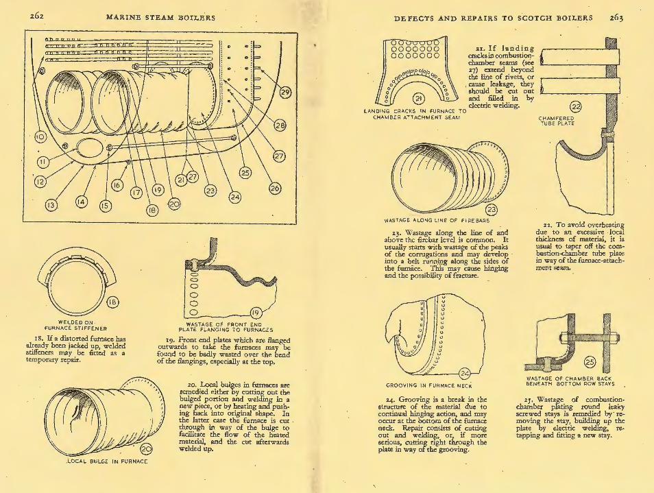
FIG. 151.-DEFECTS AND R.EPAras TO ScoTcH BoiLEas
This diagram 'illustrates the parts of a Scotch boil~r where defithectsbareilm~st _~k.ely to be found, and which should be carefully exarruned when e o er Is erng
cleTh~d~ppearance of these defects is shown in the enliuged views on the following
pa¥h~ causes of the faults and the methods of repair are dealt with in detail in PP·
2.65 to 2.73 ·

MARINE STEAM BOILERS
DISTORTED CHAMBER TUBE PLATES
I , The pushing of the tube plate inwards is caused by the tubes having been allowed to become encrusted with scale, with subsequent overheating.
WASTAGE OF SHELL. DUE TO DEFECTIVE JOINT
® NECKED STAY
2 . "Necking", or wastage of a stay tube or stay where it enters the plate, is a very common wastage defect.
OVERHEATED CHAMBER TOP
~- In the upper parts of the boiler, wastage should be looked for in parts exposed to the atmosphere, at nuts securing mountings, and, as shown abOve, around mounting joints.
4· Another defect due to overheating is distortion of the chamber crown. Accumulation of mud scale or other insulating medium may cause this.
D E F E CTS AND REPAIRS TO SCOTCH BOILERS
5· The remedy for the type of serious internal . wastage shown is to renew the stays and girders where necessary, build up chamber landings and rebed the gU:ders.
6. Wastage may be caused by stay tubes leaking at the threads. Welding around the ends will not provide sufficient INCORRECTLY anchorage for the tube. WELDED STAY WASTAGE ·OF GIRDER STAYS
CHAMBER KN UCKLES AND GI RDERS
1· Wrapper plates are often found to be badly wasted, especially around the stays and over the seams. In bad cases a new section of wrapper must be riveted and welded in.
WASTAGE CAUSED BY TUBE BLOWERS
9· Leakage past defective rivets, especially in longitudinal seams, sho~d always be viewed with suspicion. If nvet heads in vicinity are missing or fly off under hammer test a magnetic crack detector may reveal O:ustic embrittlemeot.
TUBE
8. The use of wet steam for tube blowing may cause erosion and wastage at the tube plates and tube ends.
9
0 0 0 0 0 0 0 0
o oo o oo_
o -o .ifo o...cr ~ <;r a _o o-
o 0 0
CAUSTIC EMBRITTL EMENT
FRACTURE
i 1

.z6o
WASTAGE DUE TO
LEAKAGE AT TUBE
ENDS
MARINE STEAM BOILERS
10. The front tube plate should be examined for wastage caused by leakage past defective tube ends.
II. Wastage caused through leakage of manhole-door joints is very conunon. Doors are sometil?es built up by elect~ic welding Without paymg attention to the end plate, resulting in weakening of ~ole flanging and eventual diStoruon.
12. Constant quenching of ashes below the fumace mouths causes end-plate wasta~e, and is also responsible for wastage of the collision chock immediately below.
WASTED
f-:::-=---::--=-------JCOCL~6~1~N
DEFECTS AND REPAIRS TO SCOTCH :BOILERS .z6x
GROOVING OF FRONT END PLATE
13. Grooving of a nne and sometimes deep nature may be found in front end plates which are Banged inwards to take the fumaces, especially if the radius of the flanging is small.
WASTAGE DUE TO LEAKY RIVETS
14. Wastage may be caused by leakage through defective rivets in circumferential seams, especially if the boiler has been subjected to rapid steam raising without any attempt at circulation.
.@ WASTING OF SHELL DUE TO LEAKI NG
DRAI N PLUG
1 5. Grooving is the result of mechanical action caused by varying expansion of the heating surfaces, and it may develop around lower longitudinal stays.
16. Drain plu~s, if fitted, should always be exammed. Badly fitting plll;gs are dangerous and often cause settous external wastage.
CHECKING FURNACE F OR DISTORTI ON
17. Overheating may cause deformation of fumaces • . The amount of distortion may be checked by taking a lath inside the boiler and · laying it along the corrugations at, say, four points. A method of temporary repair for distortion is shown 10 (18). .
z6z MARINE STEAM BOILERS
WELDED ON . FURNACE STIFFENER
I 8. If a distorted furnace has already been jacked up, welded stiffeners may be fitted as a temporary repair.
. LOCAL BULGE IN FURNACE
WASTAGE OF FRONT END PLATE FLANGING TO FURNACES
19. Front end plates which are flanged outwards to take the furnaces may be found to be badly wasted over the bend of the fiangings, especially at the top.
20, Local bulges in furnaces are remedied either by cutting out the bulged portion and welding in a new piece, or by heating and pushing back into original shape. In the latter case the furnace is cut . through in way of the bulge to facilitate the flow of the heated material, and the cut afterwards welded up.
DEFECTS AND REPAIRS TO SCOTCH BOILERS
21. If landing cracks in combustionchamber seams (see 27) extend beyond the line of rivets, or
, cause leakage, they should be cut out and filled in by electric welding.
lAN DING CRACKS IN FURNACE TO CHAMBER AT1 ACHM ENT SEAM
WASTAGE ALONG LINE OF FIRE BARS
23. Wastage along the line of and above the firebar level is common. It usually starts with wastage of the peaks of the corrugations and may develop into a belt runnmg along the sides of the furnace. This may cause hinging and the possibility of fracture. _
CHAMFERED TUBE PLATF
22. To avoid overheating due to an excessive ·local thickness of material, it is usual to taper off the combustion-<:hamber tube plate in way of the furnace-attachment seam.
GROOVING IN FURNACE NECK WASTAGE OF CHAMBER BACK BENEATH BOTTOM ROW STAYS
24. Grooving is a break in the structure of the material due to continual hinging action, and may occur at the bottom of the furnace neck. Repair consists of cutting out and weldin~, or, if more serious, cutting nght through the plate in way of the grooving .
25. Wastage of combustionchamber plating round leaky screwed stays is remedied by· removing the stay, buildin~ up the plate by electric weldmg, retapping and fitting a new stay.

fl .,.~':...,..,.'"",...
MARINE STEAM BOILERS
WASTAGE OF COMBUSTION CHAMBER BOTTOM WRAPPER DUE TO
SEA M LEAKAGES LANDING CRACKS IN COMBUSTION CHAMBER
:z.G. Combustion chambers are verv prone to wastage defects through leakages. If a chamber bottom appears thin, a drill test will ascertain whether smooth wastage of bottom wrappers has taken place.
27. Other defects in combustion chambers may be caused by overheating. Landing cracks, running from the plate edge to the rivet holes, may develop on the fire side, but are not serious unless very numerous and causing leakage.
OVE RH EAT ED CHAMBER . BACK PLATE
28. The water side of the combustion chamber should be kept clean, or overheating may cause bulging of the back plate between stays.
29. Wastage is often caused by leakage past defective rivets in circui:nferential, cross and longitudinal seams (r4) and past defective tube ends ( ro ). Another form of wastage, due to leakage past stay nuts, is shown hae.
WASTAGE DUE TO
LEAKING STAY NUTS
DEFECTS AND REPAIRS TO SCOTCH . BOILERS
Leakage Past Defective Rivets
Leakage past defective rivets, especially in longitudinal seams, should always be viewed with suspicion, and . if subsequent hammer testing of the rivet points results in these being dislodged, the condition of the whole seam should be investigated in view of the possibility of caustic embrittlement. Rivets should be removed from various points in the seam and the holes carefully examined. If any fractures are apparent in the bores of the holes, a magnetic crack detector applied to the defective plate will reveal their extent, Fig. I 5 I (9). In the case of a double butt-strap joint this may necessitate the removal of the straps. However, there are other causes of rivet points breaking away from their shanks, such as defective material, overheating, initial faulty workmanship, etc., and it is well to bear this in mind.
Wastage at Mountings
It is also desirable to consider the advisability of examining the necks and joints of mountings such as check valves, scum valves, etc., especially when these are covered with lagging. In a recent case the necks and joints of the valves were covered with asbestos lagging and portable plates, and it was only after some persuasion that these were removed-whereupon the scum~ valve chest was found to be badly salted up around the neck, and during the chipp1ng operations necessary to remove the salt the chest broke away from the neck holding it to the boiler shell.
Circumferential Seam Leakage
The lower parts of the boiler also call for attention. Wastage is very often found where there has been circumferential seam leakage, Fig. I5I (I4), especially if the boiler has been subjected to such ill-treatment as rapid steam raising without any attempt at circulation. Here again a recent case showed the shell to be so wasted under the lagging in way of a circumferential seam leakage that a hammer test pierced the shell plate. The repair · for this defect consisted of an internal riveted patch welded on to and forming an extension of the end-plate flanging.
Leakage at Manhole-door Joints
Wastage caused through the leakage of manhole-door joints is very common, and it is worth noting that the doors are some
s

266 MARINE STEAM BOILERS
times built up by electric welding without payirig attention to the end plate, with the result that although the door is made a passable fit, the lower part of the manhole flanging is gradually weakened, and eventually fails to react .equally all rqund to the pull of the door dogs, Fig. 15.1 (11), thereby producing distortion.
Wastage of End Plate and Collision Chocks The constant quenching of ashes below the furnace mouths
causes wastage of the end plate, which, on account of its smooth nature, may easily be missed. It is also responsible for the wastage of the collision chock immediately below, Fig. I5I (12).
• A point concerning collision chocks is that some makers favour a chock in the form of a small doubler on the boiler shell which bears against one of the boiler stools. If, therefore, an examination fails to reveal the presence of a normal-type chock, one of this variety may be .found hidden from view beneath the lagging.
Leaking Drain Plugs When examining the lower part of the boiler internally it is
essential to ascertain whether or not a drain plug is fitted, in order that its condition may be noted when the external examination of the shell is being made. Badly fitting drain plugs, apart from being dangerous, often cause serious external wastage,
.Fig. 151 (I6).
Wastage of Combustion Chambers In addition to the external parts of the shell, the fire side of
the furnaces and combustion chambers must be considered. The fire side of the furnaces can be more or less ruled out as far as wastage is concerned, unless this takes place as a result of leaky seams. Owing to the number of their seams and the severe racking strains to which they are subjected, combustion chambers are, however; very prone to wastage defects through leakages, shown in Fig. I5 I (i6). The smooth wastage of combustionchamber bottom wrappers is a particularly elusive type of defect. The seams are a good guide in this matter, but if the plate is judged to be seriously reduced, drill tests will confirm any doubt. In cases where a chamber bottom appears thin and its seams have been previously welded over, a drill test is essential.
DEFECTS AND REPAIRS TO SCOTCH BOILERS
Wastage of Stay-tube Threads Tubes, both stay and plain, of dirty boilers are liable to 9Ver
heat and cause excessive expansion, with consequent working of the tubes in their tube plates, the result being a leakage and wasting of the stay-tube threads.
If stay-tubes leak at the threads and cause local wastage, expanding may, if the threads are good, constitute a cure, but on no account should they be welded around the ends, as the shear resistance of this small fillet weld may be the only anchorage of the tube, Fig. I p (6).
The above remark concerning the welding of stay-tube ends is . also applicable to the nutless type of combustion-chamber screwed stay.
Wastage of Combustion-chamber Plating _ __ Wastage of combustion-chamber plating around leaky ~cre~ed
stays, especially beneath those in the back bottom row, 1~ fa1rly common, Fig. IP (25), and can nearly always be r~medied. by removing the stay, building up the plate b-y electriC welding, re-tapping and fitting a new stay. .
Before leaving combustion chambers, there 1s another form of wastage which should be mentioned, the combined effect of erosion and wastage caused by a high-pressure. jet of w~t steam impinging on some part of the chamber. This defect 1s often caused by the use of wet steam for tube blowing, in which case the tube plates and tube ends suffer, Fig. I 51 (8), or through serious leakage at a defective seam, stay-nut or tube.
Internal Wastage . Neglected boilers, and particularly 'tween-d~ck auxilia~y
boilers, are liable to suffer from wastage on .practically all the1r internal surfaces and common defects are senous wastage of the combustion-cha~ber girders, stays and knuckles of the tube and back plates, Fig. I p (5 ). It is quite usual to find the girder toes wasted to such an extent that they are clear of the chamber. The remedy for this is . to renew the stays and girders where necessary, build up chamber landings where required and re-bed the girders.
Wastage of Wrapper Plates Wrapper plates are frequently found to be. badly wast~d,
especially around the stays and over the seams, F1g. 151 (7), and

z68 MARINE STEAM BOILERS
in bad cases the only thing to be done is to cut out the defective portion of wrapper and to rivet and weld in a new section. Sometimes it is only a matter of wastage around the ·stays, and in this case the usual repair is to remove the latter and build up a compensating pad on the fire side by electric welding, re-tap and fit new stays. An alternative method of repair is to reruove the stays and, working with extra long electrodes through the stay
: holes in the boiler back plate, to build up the wasted places and refit the stay. ,
When dealing with wastage over wrapper seams, it should always be borne in mind that the chamber is in compression, and provided that the rivets are not seriously reduced and the seam is tight, wastage of the wrapper outside of the line of rivets is not a very serious matter, Fig. I 5 I (7).
Wastage of the combustion-chamber tube plates around the stay tubes and the back plates around stays is a frequent occurrence, and here also electric welding can be employed to make good the wastage after the tube or stay has been removed.
Wastage of Stay Tubes and Stays
In the lower parts of the boiler, wastage of a stay tube or stay at the point where it enters the plate- usually known as " necking" Fig. I 5 I (z)-is one of the most common wastage defects. It is accelerated by the straining imposed on the stays by the . expansion and contraction of the combustion chamber due to temperature changes.
A point to remember with wasted stays is that their strength varies as the square of the diameter and that it is quite a simple · matter to compare the smallest wasted diameter with the diameter .at the bottom of the thread.
Stay tubes sometimes blister and pit, the pits being small and deep. Such pits can be quite enough to condemn the stay tubes, although their strength may not appear to be affected. On the other hand, the stay tubes may be so badly wasted that only the removal of a tube can give any guide as to their general condition. This course was recendy taken in the case of a 'tweendeck donkey boiler, the stay . tubes removed being only onethird of the weight of the new tubes replacing them.
Wastage of Furnace
Wastage of furnaces along the line of and above the firebar level is a· very common occurrence which is often serious. It
DEFECTS AND REPAIRS 'fO SCOTCH BOILERS 269
usually starts with a wastage of the peaks of the corrugations, and if not checked or made good by electric welding, this rapidly develops into a belt running along the sides of the furnace, Fig. I 5 I (23). The result of any such wasting at the side.s ~~ a tendency for hinging along the line· of weakness and a possibility of subsequent fractures. Drill testing, gauging, careful examination and, if possible, an insight into its previous history must serve to decide whether or not a furnace is still in a safe condition.
Wastage at Flanges Flanges of small radius should always be viewed with suspicion,
especially when they are likely to be subjected to varying loads. Front end plates flanged outwards to take the furnaces, Fig. I 5 I (I9), are sometimes found to be badly wasted over the bend of~he flangings, especially at the top, such wastage probably being accentuated by the furnaces.
Wastage at Boiler Bottom In neglected boilers, water which has accumulated through
condensation is sometimes allowed to remain in the bottom for long periods, with the result that pitting dev~lops. This,. in conjunction with the possibility of an accumulation o~ c?rro~Ive deposits through poor circulation, soon turns the prttmg mto wasted areas. When these areas are large, drill testing and calculations based on the remaining thickness are the best means of deciding whether the shell is stil,l_able to withstand the normal working pressure without repairs . ... · ·
OVERHEATING
Defects caused through overheating are liable to be developed in the furnaces, combustion chambers and tubes. It is proposed to deal with these three parts individually and to discuss the repairs.
Furnaces . Overheating and subsequent deformation of furnaces is always
caused by the presence of some insulating II,ledium between the furnace and the surrounding water. This medium can be steam, scale, mud or oil, and its effect may be further increased by local overheating due to faulty combustion. It is not proposed, however, to deal with the causes of the defects, but merely to enumerate them.

2.70 MA)'l.INE STEAM BOILERS
The usual way of getting some idea as to whether a furnace is passably round is to sight along the corrugations with a torch from inside the combustion chamber. If this test .shows the furnace to be distorted (a matter of experience), one of the best methods of obtaining an accurate idea of how much it has altered from its original shape i~ to take a lath inside the boiler and lay it along the corrugations at say, four points, Fig. I5I (17).
No definite rule can be stated as to whether or not a furnace needs renewal owing to its distorted shape ; age, corrosion, acuteness and area of deformation, and previous history should all be taken into account. Local bulges, Fig. I 51 (zo ), can often be rectified by heating and pushing back into original shape. When this is done it is essential to cut the furnace through in way of the bulge in such a manner that the :flow of the heated material is facilitated, the cut in the furnace being subsequently welded up.
As an alternative to this procedure, and where experienced welders are available, the bulged portion can be completely cut out and a new piece welded in place.
If a furnace is uniformly down to such an extent as to call for immediate action, provided the material is good and the surfaces not severely corroded, quite a satisfactory repair can be effected by wanning up and jacking back the furnace to its original shape, care being taken to examine the furnace carefully for cracks after the jacking operation.
Occasionally one is faced with a distorted furnace, considerably corroded along the line of firebars, which has already been jacked up, and for which no spare is immediately available. As a temporary repair, jacking back to approximately original shape and the fitting of welded stiffeners, Fig. 151 (IS), is sometimes resorted to.
Distorted furnaces may give rise to differences of opinion when examining boilers, but if the distortion is really serious, the only remedy is to renew the furnace.
Combustion Chambers
Overheating is responsible for numerous defects in combustion chambers, !llld it is proposed to start from the upper parts and work downwards.
The first part of a boiler to feel the effects of overheating through lack of water is the chamber crown. An accumulation
DEFECTS AND REPAIRS TO SCOTCH .BOILERS 2.7I
of mud scale or other insulating medium on the top of the chamber can also cause similar defects, Fig. I 5 I (4).
Proceeding lower down the chamber into parts which. are subjected to more intense heat, it is quite common, espee1ally in boilers which are not kept clean, to find the back plate bulged between the stays, Fig. 151 (zS). A bulged plate accumulates scale and mud, and so promotes further o:rerheating and . an extension of the bulge. Provided the bulgmg of the plating between stays is not very extensive and has not stretched the material in way · of the stay holes, so as to cause leakage, the obvious remedy is to keep the water side of the plating as clean as possible, in order to prevent further overheating. ·. . When the chamber plating is bulged to such an extent that lt is deemed necessary · to effect repairs, it is inadvisable to . fit additional stays in way of bulges, as they. promote the format10n of further deposits and make the plates less easy to ~~e, added to which the extra stays with their nuts form additional local . uncooled areas. The only remedy for plating in this condition is renewal.
The partial renewal of combustion-chamber backs is a very common· repair, and a question which sometimes arises is whether the plating should be cut through the lines o~ stays or betw~en them. A factor in favour of the first method 1s that the welding is in short lengths between the stay holes and not one long c~mtinuous weld, hence the possibility of fractures from contraction stresses is more remote.
The seams of combustion chambers are liable to overheat on their fire sides, because there is a double thickness of metal between the heating surface and the surrounding water. The result is that so-called landing cracks develop, Fig. Iji (2.7). These cracks may run from the plate edge to the rivet holes, and when dry can be ignored, provided they are not too nu~erous. If, however, the cracks originating at ·the plate edge d~ not terminate at the rivet holes and tend to extend beyond the line of rivets, Fig. 151 ( 2.1 ), or if leakage develops in way of the cr~cks, they should be cut out and filled in by electric ~elding, the nv:ets · in the vicinity of the cracks being removed pnor to the welding operations and subsequently renewed. · . .
The most usual place for landing cracks to develop lS l!l the upper parts of the seam connecting the combustion cJ:lamber t_o the furnace which in view of the intense heat at this seam 1s understand~ble. It is not advisable to ignore a series of such

. MARINE STEAM BOILERS .
fractures in this seam, as the ligaments between the fractures might conceivably be subjected to bending stresses through variations in the length of the furnace, due to temperature changes and straining action. Nowadays, especially in the case of heavy combustion-chamber tube plates, it is usual to taper off the plate in way of the furnace-attachment seam, Fig. I 5 I (u), this being an obvious way of avoiding overheating due to an excessive local thickness of material.
Tubes
Tubes which are allowed to become encrusted with scale are liable · to overheating defects. In the first place the tubes, especially stay tubes, are subjected to undue expansion, with the result that they tend to push the tube plate inwards, Fig. I 5 I (1). In a dirty boiler this can be checked _by laying a straight edge across the tube plate.
Second, this tendency to excessive expansion causes the tubes to move, and leads to leakage at the end which has the weaker anchorage, the combustion-chamber tube-plate end.
Third, the tube ends in the combustion chamber, especially the lower rows, tend to burn and wear thin.
COMBINED EFFECT OF CORROSION . AND MECHANICAL ACTION
The defects coming under this heading are practically all to be found on the water side in the lower half of the boiler. Poor circulation, rapid steam raising, continued forcing, irregular firing, lack of uniformity of stiffness in design-such faults, often accentuated by the action of indifferent feed-water, are all factors
. in producing the defects now claiming attention. The areas of the heating surfaces of the furnaces, combustion chambers and tubes vary according to the temperature, and it is these variations which give rise to some of the defects caused by straining or mechatiical action.
Variations in the length of the furnaces are to some extent taken up by the corrugations, but the chamber-end flanging attachment is stiffer at the top of the furnace than at the bottom, due to the form of the Gourlay neck, and hinging is liable to take place at the most flexible part, i.e., at the bottom. This results in what is commonly called " grooving ", Fig. I 5 I ( 2.4), which is a break in the structure of the material due to continual hinging
DEFECTS AND REPAIRS TO SCOTCH BOILERS 273
action. Grooving develops with age and accelerates as the material gets weaker.
In view of the fact that there are flanged attachments at both ends of the furnace, it is only logical to expect both to be subjected to straining action. In'the case of front-end plates which are flanged inwards to take the furnaces, especially if the radius of the flanging is small, grooving of a fine and sometimes deep character is not unusual, Fig. I 5 r (I;). When the front end plate is flanged outwards to take the furnaces, grooving in the front flanging is uncommon and, if present, is usually of a broader nature, Fig. I5I (I9)·
Repairs for Grooving The procedure for dealing with grooving is to pick out what
appears to be the most serious pru;t,_to _clJ;.iU a ! or § in. hole through it and, by exaiiiillfug the bore of the hole, to ascertain its depth. The repakror the grooving when it is not more than, say, 50 per cent of the plat~~:Sin-depth, is to cut it out and weld. If, howe~<::_!:._ it i~ of a m&r-e serious nature, it is usually best, provided both sides of the.JYJ!.~e=are accessible for welding operations, to cut right throug~:£!ate in way of the grooving.
As has already been_sai_d, gi(i~is the result of mechanical action caused by--varyicrg· :expan-sio~ of the -heating surfaces. Any ·variation in length_Qf}IieTurnace and combustion-chamber assembly with the temperature~~Q that of the boiler shell due to poor circulation, leads to wo'fklng of the lower parts of the boiler end_:-plate flangings and-·of""flle end plates where tied by stays. These defects are sM.wrrin Fig. IP (I;) and (15). The repair for grooving of ~late flanges is the same as for grooving in the furnace-attac:lfment fl:anges-to cut out and weld.
Where radial grooving--are't'lftd--- lower longitudinal stays develops, as in Fig. rJI-(-ll:k·welcling--does not, as a rule, constitute a permanent repair, and the local stress concentrations at the stay ends should be spread-o-ver a larger area by fitting a doubler in way Q[ the stay, suitably riveted to the end plate.
Similar radial grooving sometimes takes place around the stay tubes and combustion-chamber side and backstays,more especially at the combustion-chamber end. The repair in this case is to remove the stay or tube, cut out the grooving, weld up and subsequently refit the stay or tube. Doubling of heating surfaces is not permissible, as this would result in overheating.