marine power supply systems - philippi-online.de · n º 17 marine power supply systems...
TRANSCRIPT

Nº1
7
M A R I N E
P O W E R S U P P L Y S Y S T E M S
D I S T R I B U T I O N P A N E L
O N - B O A R D M O N I T O R I N G
B A T T E R Y C H A R G E R
A C S H O R E P O W E R
D C I N S T A L L A T I O N
C O N N E C T O R S
W I R I N G
L E D L I G H T S
MA
RIN
E P
OW
ER
SU
PP
LY
SY
ST
EM
S
BO
AT
SH
OW
PR
ES
EN
TATI
ON
and its distributors are present on many important boatshows all around Europe.On these boat shows you will receive a large amount of information regarding electrical boat equip ment. You will also get an insight of discussions betweenboat operators and manufacturer.Perhaps you would like to exchange ideas or experiences.
bootDüsseldorf
hansebootHamburg
METSAmsterdam
Salon NautiqueParis
N° 17
01
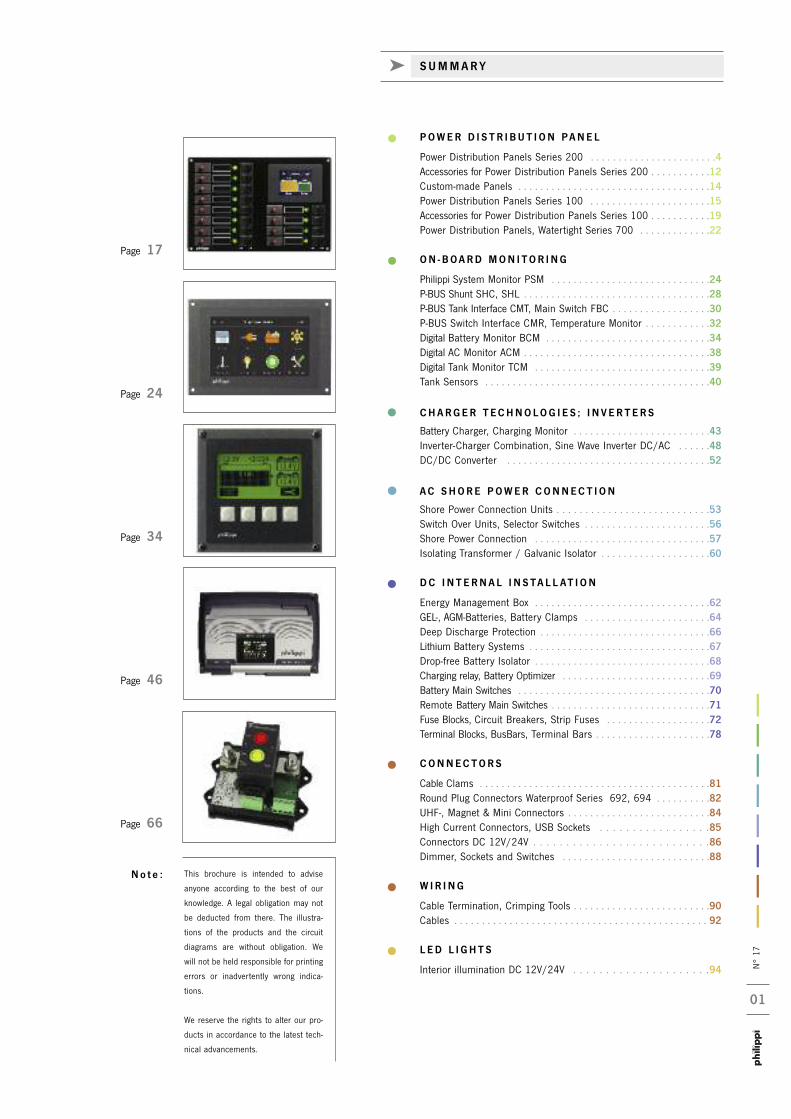
C POWER D I S T R I BU T I ON PANE L
Power Distribution Panels Series 200 . . . . . . . . . . . . . . . . . . . . . . .4Accessories for Power Distribution Panels Series 200 . . . . . . . . . . .12Custom-made Panels . . . . . . . . . . . . . . . . . . . . . . . . . . . . . . . . . . .14Power Distribution Panels Series 100 . . . . . . . . . . . . . . . . . . . . . .15Accessories for Power Distribution Panels Series 100 . . . . . . . . . . .19Power Distribution Panels, Watertight Series 700 . . . . . . . . . . . . .22
C ON - BOARD MON I TOR I NG
Philippi System Monitor PSM . . . . . . . . . . . . . . . . . . . . . . . . . . . . .24P-BUS Shunt SHC, SHL . . . . . . . . . . . . . . . . . . . . . . . . . . . . . . . . . .28P-BUS Tank Interface CMT, Main Switch FBC . . . . . . . . . . . . . . . . . .30P-BUS Switch Interface CMR, Temperature Monitor . . . . . . . . . . . .32Digital Battery Monitor BCM . . . . . . . . . . . . . . . . . . . . . . . . . . . . . .34Digital AC Monitor ACM . . . . . . . . . . . . . . . . . . . . . . . . . . . . . . . . . .38Digital Tank Monitor TCM . . . . . . . . . . . . . . . . . . . . . . . . . . . . . . . .39Tank Sensors . . . . . . . . . . . . . . . . . . . . . . . . . . . . . . . . . . . . . . . . .40
CHARGER T ECHNOLOG I E S ; I N V ER TERS
Battery Charger, Charging Monitor . . . . . . . . . . . . . . . . . . . . . . . . .43Inverter-Charger Combination, Sine Wave Inverter DC/AC . . . . . .48DC/DC Converter . . . . . . . . . . . . . . . . . . . . . . . . . . . . . . . . . . . . .52
AC SHORE POWER CONNECT I ON
Shore Power Connection Units . . . . . . . . . . . . . . . . . . . . . . . . . . .53Switch Over Units, Selector Switches . . . . . . . . . . . . . . . . . . . . . . .56Shore Power Connection . . . . . . . . . . . . . . . . . . . . . . . . . . . . . . . .57Isolating Transformer / Galvanic Isolator . . . . . . . . . . . . . . . . . . . .60
DC I N T ERNA L I N S TA L L AT I ON
Energy Management Box . . . . . . . . . . . . . . . . . . . . . . . . . . . . . . . .62GEL-, AGM-Batteries, Battery Clamps . . . . . . . . . . . . . . . . . . . . . . .64Deep Discharge Protection . . . . . . . . . . . . . . . . . . . . . . . . . . . . . . .66Lithium Battery Systems . . . . . . . . . . . . . . . . . . . . . . . . . . . . . . . . .67Drop-free Battery Isolator . . . . . . . . . . . . . . . . . . . . . . . . . . . . . . . .68Charging relay, Battery Optimizer . . . . . . . . . . . . . . . . . . . . . . . . . . .69Battery Main Switches . . . . . . . . . . . . . . . . . . . . . . . . . . . . . . . . . . .70Remote Battery Main Switches . . . . . . . . . . . . . . . . . . . . . . . . . . . . .71Fuse Blocks, Circuit Breakers, Strip Fuses . . . . . . . . . . . . . . . . . . .72Terminal Blocks, BusBars, Terminal Bars . . . . . . . . . . . . . . . . . . . . .78
CONNECTORS
Cable Clams . . . . . . . . . . . . . . . . . . . . . . . . . . . . . . . . . . . . . . . . . .81Round Plug Connectors Waterproof Series 692, 694 . . . . . . . . . .82UHF-, Magnet & Mini Connectors . . . . . . . . . . . . . . . . . . . . . . . . . .84High Current Connectors, USB Sockets . . . . . . . . . . . . . . . . .85Connectors DC 12V/24V . . . . . . . . . . . . . . . . . . . . . . . . . . .86Dimmer, Sockets and Switches . . . . . . . . . . . . . . . . . . . . . . . . . . .88
W IR I NG
Cable Termination, Crimping Tools . . . . . . . . . . . . . . . . . . . . . . . . .90Cables . . . . . . . . . . . . . . . . . . . . . . . . . . . . . . . . . . . . . . . . . . . . . . 92
L ED L I GHT S
Interior illumination DC 12V/24V . . . . . . . . . . . . . . . . . . . . .94
This brochure is intended to advise
anyone according to the best of our
knowledge. A legal obligation may not
be deducted from there. The illustra-
tions of the products and the circuit
diagrams are without obligation. We
will not be held responsible for printing
errors or inadvertently wrong indica-
tions.
We reserve the rights to alter our pro-
ducts in accordance to the latest tech-
nical advancements.
No t e :
Page 46
Page 34
Page 17
Page 24
Page 66
k SUMMARY

N° 17
02
Dear Customers,
for more than three decades we have been designing and manufactu-ring products within the battery and transformer technology. On thebase of experiences in this specialised field combined with the know-ledge of requirements in the marine environment, we have been ableto develop the total package now known and recognised as the philippi marine electrical system.
Production commenced in 1978 and philippi gmbh has been in exis-tence over 38 years during which time marine electrical technologyhas advanced substantially into the high-tech field. Our company wasthe first commercial enterprise in marine electrical products to incor-porate the parameters and regulations of VDE/EN ISO andGermanischer Lloyd authorities. With continuous innovations such asthe introduction of automatic charging equipment and digital batteryand tank monitors we have made an important contribution towardsthe present level of progress.
Over the last 30 years there has been a rapid development in this product group in response to demand on the part of boat builders,dealers and private owners seeking dependable electrical systems. Inthe meantime we have built up contacts and have established supply
contracts with boat builders and customers in Europe andoverseas.Twice our workshops proved too small for our operationsso that we built a new factory which we occupied in 1991.This new facility enabled us to expand our production pro-gram as well as to enlarge our research and developmentactivity to meet the latest demands of the industry. We are also engaged in the distribution of products of suchrenown companies as Binder, E-T-A, Turotest and Pro-Car in Germany and other countries.
We are actively engaged in further development of electri-cal equipment through our involvement in such importantinstitutions as the German Boat and Ship BuildersAssociation - Hamburg and the Federal Economic Societyof Pleasure Craft - Köln. We are the founder of the workinggroup „Electrics and electronics for yachts“ in the DBSV.
Michael Kögel and the - team
All of our developed equipment and switch boards combine a logical layout with an attractive and pleasing design.Main features are safety of operation and simplicity of control, especially in emergencies.
The professional maritime marine and skippers of sailing yachts and power boats demand that electrical installa-tions on board must comply with stringent requirements. The personal safety of crew and passengers must alwaysbe guaranteed. Therefore, we manufacture to standards approved and sanctioned by the leading responsibleauthorities.
The marine environment is aggressive and vibration, salt water and air means that equipment and componentsmust be specially protected in order to with-stand the effects of corrosion.All our equipment offers a high degree of resistance through the use of non-corroding materials such as alumi-nium, stainless steel, thermoplastics, immersed and baked transformers and thus ensure a long service life andobviates early failure and corrosion of components.
We grant a warranty to our products of two years. You can be sure that we will assist you in any case of pro-blems with our products.
All our manufactured products have been developed in house and have been tested in operation. This guaranteesa continuously high level of quality as well as a rapid response and complete service package.Should you have any queries regarding our products please consult with our local dealer or ourselves. Our staffwill be happy to deal with any questions or technical problems.
Function and Design
Saftey
Durability and Operating Life
Warranty
Made in Germany
k I MPOR TANT CHAR ACTER I S T I C S O F OUR EQU I PMENT S
Our facilities in Remseck. Here we`re . . . developing new products, . . . producing carefully . . . handling your orders.
k T ECHN I CA L PER F ECT I ON AND QUA L I T Y. D ECADES O F E X PER I ENCE

N° 17
03
For completion of our product range we work together with well-knownGerman and international companies. We favour companies producing tothe highest standards and also are situated in the German speaking part
in order to get best quality products together with best technical assis-tance and knowledge in special details.
Our most important partners are:
k OUR PAR TNERS FOR B E S T QUA L I T Y E L EC TR I CA L COMPONENT S
Connectors Connectors
Circuit breakers Sine wave inverters, combis
Connectors / Switches Main switches and relays
DC/DC-converters Gensets
DC-Installation LED-lights
The CE classification indicates that the marked product is in accordance to the current and
relevant legal requirements which are based on European guidelines. From 1996, for instance,
only equipment which conforms to the EMV guidelines may be brought into the market . The CE
classification does not refer to the quality of the product and, therefore, does not express an
indication of quality.
All our manufactured and distributed products conform to the European and national safety
regulations. Guideline 73/23 EEC of the Council of the European Union and Equipment Safety
Law (GSG). In addition the requirements related to radio interference.
Guideline 89/336 EEC amended by 91/263/EEC, 92/31EEC of the Council of the European
Union and the EMV Law.
With the CE classification philippi marine electrical systems declare, according to the regulations
of the guidelines 73/23/EEC and 89/392/EEC, that their products bearing this classification
conform to the above named norms and the specific related documents. Legal warranty and lia-
bility may not be deduced from this confirmation.
k THE - C L A S S I F I C AT I ON
N° 17
04
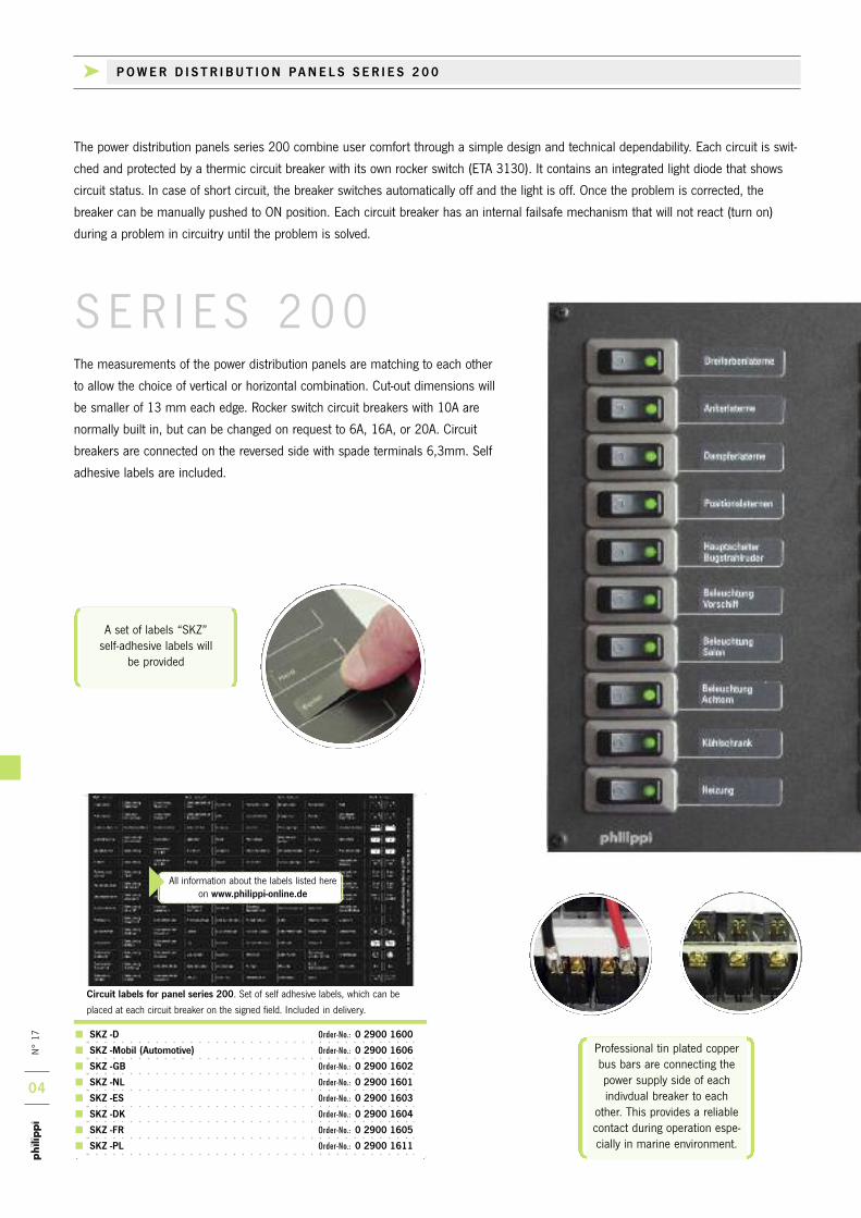
A set of labels “SKZ” self-adhesive labels will
be provided
Professional tin plated copperbus bars are connecting thepower supply side of eachindivdual breaker to each
other. This provides a reliablecontact during operation espe-cially in marine environment.
SKZ -D Order-No.: 0 2900 1600
SKZ -Mobil (Automotive) Order-No.: 0 2900 1606
SKZ -GB Order-No.: 0 2900 1602
SKZ -NL Order-No.: 0 2900 1601
SKZ -ES Order-No.: 0 2900 1603
SKZ -DK Order-No.: 0 2900 1604
SKZ -FR Order-No.: 0 2900 1605
SKZ -PL Order-No.: 0 2900 1611
Circuit labels for panel series 200. Set of self adhesive labels, which can be
placed at each circuit breaker on the signed field. Included in delivery.
All information about the labels listed hereon www.philippi-online.de
S ER I E S 2 0 0
The power distribution panels series 200 combine user comfort through a simple design and technical dependability. Each circuit is swit-
ched and protected by a thermic circuit breaker with its own rocker switch (ETA 3130). It contains an integrated light diode that shows
circuit status. In case of short circuit, the breaker switches automatically off and the light is off. Once the problem is corrected, the
breaker can be manually pushed to ON position. Each circuit breaker has an internal failsafe mechanism that will not react (turn on)
during a problem in circuitry until the problem is solved.
The measurements of the power distribution panels are matching to each other
to allow the choice of vertical or horizontal combination. Cut-out dimensions will
be smaller of 13 mm each edge. Rocker switch circuit breakers with 10A are
normally built in, but can be changed on request to 6A, 16A, or 20A. Circuit
breakers are connected on the reversed side with spade terminals 6,3mm. Self
adhesive labels are included.
k POWER D I S T R I BU T I ON PANE L S S E R I E S 2 0 0
N° 17
05
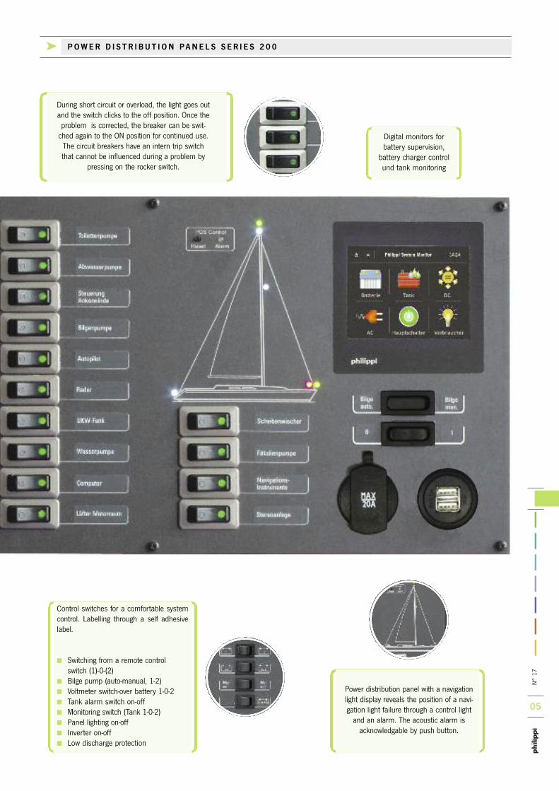
During short circuit or overload, the light goes outand the switch clicks to the off position. Once theproblem is corrected, the breaker can be swit-ched again to the ON position for continued use.The circuit breakers have an intern trip switchthat cannot be influenced during a problem by
pressing on the rocker switch.
Digital monitors for battery supervision, battery charger controlund tank monitoring
Power distribution panel with a navigationlight display reveals the position of a navi-gation light failure through a control lightand an alarm. The acoustic alarm is acknowledgable by push button.
Control switches for a comfortable systemcontrol. Labelling through a self adhesivelabel.
Switching from a remote control switch (1)-0-(2)
Bilge pump (auto-manual, 1-2) Voltmeter switch-over battery 1-0-2 Tank alarm switch on-off Monitoring switch (Tank 1-0-2) Panel lighting on-off Inverter on-off Low discharge protection
k POWER D I S T R I BU T I ON PANE L S S E R I E S 2 0 0

N° 17
06 8 power circuits with thermal circuit breakers 10 A
Dimensions W 210 x H 105 x D 70 mm
Suitable terminal blocks type RKL 10
2 power circuits with thermal circuit breakers 10 A and display power boat incl.
electronic navigation lights monitor POS 6 with alarm, for use with LED -lanterns or
normal bulbs, for 12V and 24V
Dimensions W 210 x H 105 x D 70 mm
STV 208 Order-No.: 0 2000 2080 STV 202 MS Order-No.: 0 2002 2026
10 power circuits with thermal circuit breakers 10 A.
Dimensions W 105 x H 210 x D 70 mmSuitable terminal blocks type Type RKL 10.
7 power circuits with thermal circuit breakers 10 A,DC - and dual USB charging socket.
Dimensions W 105 x H 210 x D 70 mmSuitable terminal blocks type Type RKL 10.
4 power circuits with thermal circuit breakers 10A,display sailing yacht incl. electronic navigationlights monitor POS 6 with alarm, for use with LED-lanterns or normal bulbs, for 12V and 24V
Dimensions W 105 x H 210 x D 70 mm
STV 207 Order-No.: 0 2000 2071 STV 204 SY Order-No.: 0 2002 2041
7 power circuits with thermal circuit breakers 10 A, battery monitor BCM 1, (alter-natively tank monitor TCM4V) and 2 control switches for individual use. Shunt SHA has to be ordered separately (please see page 37) !
Dimensions W 210 x H 157,5 x D 70 mmSuitable terminal blocks type RKL 10
7 power circuits with thermal circuit breakers 10A, illuminated voltmeter with switchover.
Dimensions W 105 x H 210 x D 70 mmSuitable terminal blocks type RKL 10
STV 227 -12V Order-No.: 0 2001 2270
STV 227 -24V Order-No.: 0 2002 2270 STV 217 Order-No.: 0 2000 2170
STV 210 Order-No.: 0 2000 2100
k POWER D I S T R I BU T I ON PANE L S S E R I E S 2 0 0
N° 17
07
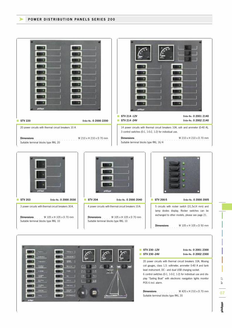
STV 200-5 Order-No.: 0 2000 2005 STV 204 Order-No.: 0 2000 2040 STV 203 Order-No.: 0 2000 2030
5 circuits with rocker switch (31,5x14 mm) and
lamp diodes display. Rocker switches can be
exchanged to other models, please see page 21.
Dimensions W 105 x H 105 x D 50 mm
20 power circuits with thermal circuit breakers 10A, Moving
coil gauges, class 1,5: voltmeter, ammeter 0-40 A and tank
level instrument. DC - and dual USB charging socket.
6 control switches (0-1, 1-0-2, 1-2) for individual use and dis-
play “Sailing Boat” with electronic navigation lights monitor
POS 6 incl. alarm.
Dimensions W 420 x H 210 x D 70 mm
Suitable terminal blocks type RKL 20
STV 230 -12V Order-No.: 0 2001 2300
STV 230 -24V Order-No.: 0 2002 2300
20 power circuits with thermal circuit breakers 10 A
Dimensions W 210 x H 210 x D 70 mm
Suitable terminal blocks type RKL 20
3 power circuits with thermal circuit breakers 30A.
Dimensions W 105 x H 105 x D 70 mmSuitable terminal blocks type RKL 10
4 power circuits with thermal circuit breakers 10A.
Dimensions W 105 x H 105 x D 70 mmSuitable terminal blocks type RKL 10
14 power circuits with thermal circuit breakers 10A, volt- and ammeter (0-40 A),
3 control switches (0-1, 1-0-2, 1-2) for individual use.
Dimensions W 210 x H 210 x D 70 mm
Suitable terminal blocks type RKL 16/4
STV 214 -12V Order-No.: 0 2001 2140
STV 214 -24V Order-No.: 0 2002 2140
k POWER D I S T R I BU T I ON PANE L S S E R I E S 2 0 0
STV 220 Order-No.: 0 2000 2200

N° 17
08
STV 222 Order-No.: 0 2002 2220
15 power circuits with thermal circuit breakers10 A, battery monitor BCM 1(alternatively tankmonitor TCM 4V can be ordered). Shunt SHA has to be ordered separately !
Dimensions W 210 x H 210 x D 70 mm
Suitable terminal blocks type RKL 16/4
STV 215 Order-No.: 0 2000 2150
24 power circuits with thermal circuit breakers 10 A, battery monitor BCM 1 (alternatively tank monitor TCM 4Vcan be ordered), display sailing yacht incl. navigation lights monitor POS 6 with alarm, 1 DC - and 1 dual USB charging socket and 2 control switches for individual use. Shunt SHA has to be ordered separately (see page 37)!
Dimensions W 420 x H 210 x D 70 mm
Suitable terminal blocks type RKL 30
STV 224 Order-No.: 0 2002 2240
20 power circuits with thermal circuit breakers 10 A, battery monitor BCM 1, tank monitor TCM 4V, display sailing yacht incl. navigation lights monitor POS 6 with alarm, 1 DC - and 1 dual USB charging socket and 2 con-trol switches (0-1, 1-0-2) for individual use. Shunt SHA has to be ordered separately (see page 37)!
Dimensions W 420 x H 210 x D 70 mm
Suitable terminal blocks type RKL 20
STV 228 Order-No.: 0 2000 2280
8 power circuits with thermal circuit breakers 10A,battery monitor BCM 1, tank monitor TCM 4V, dualUSB charging socket and 2 control switches forindividual use. Shunt SHA has to be ordered separately !
Dimensions W 210 x H 210 x D 70 mmSuitable terminal blocks type RKL 10
The models STV 222, STV 224 and STV 264 offer the complete protec-tion and monitoring for a medium sized sailing yacht with one panel possible. Apart from the thermal protection of the electric circuits a navigation lights monitoring with notification of failure is available.There are also control switches for individual use, e.g. remote control of
main switches, bilge pump automatics, inverter, loudspeaker change overand further arbitrary applications. Instead of the digital battery monitorBCM 1 a tank monitor TCM 4V can be ordered also.An active shunt for the battery monitor BCM and the P-BUS componentsfor the PSM have to be ordered separately!
k POWER D I S T R I BU T I ON PANE L S S E R I E S 2 0 0
N° 17
09
NEW
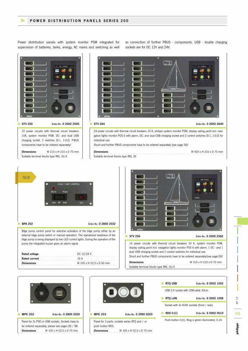
Panel for 3 parts: sockets series RTQ and / or
push button RDS.
Dimensions W 105 x H 52,5 x D 70 mm
MPE 203 Order-No.: 0 2990 0203
RTQ USB Order-No.: 6 0002 1002
USB 2.0 socket with USB-cable 30cm.
RTQ LAN Order-No.: 6 0002 1008
Socket with 2x RJ45 sockets (front / rear).
RDS 0-(1) Order-No.: 6 0002 0010
Push button 0-(1), Ring is green illuminated, 0,1A
MPE 202 Order-No.: 0 2800 2020
Panel for 2x PSD or USB sockets. Sockets have to
be ordered separately, please see pages 85 / 88.
Dimensions W 105 x H 52,5 x D 70 mm
Power distribution panels with system monitor PSM integrated for supervision of batteries, tanks, energy, AC mains and switching as well
as connection of further PBUS - components. USB - double chargingsockets are for DC 12V and 24V.
STV 250 Order-No.: 0 2002 2500 STV 264 Order-No.: 0 2002 2640
10 power circuits with thermal circuit breakers
10A, system monitor PSM. DC- and dual USB
charging socket, 2 switches (0-1, 1-0-2). P-BUS
components have to be ordered separately!
Dimensions W 210 x H 210 x D 70 mm
Suitable terminal blocks type RKL 16/4
24 power circuits with thermal circuit breakers 10 A, philippi system monitor PSM, display sailing yacht incl. navi-
gation lights monitor POS 6 with alarm, DC- and dual USB charging socket and 2 control switches (0-1, 1-0-2) for
individual use.
Shunt and further PBUS components have to be ordered separately (see page 26)!
Dimensions W 420 x H 210 x D 70 mm
Suitable terminal blocks type RKL 30
k P O W E R D I S T R I B U T I O N P A N E L S S E R I E S 2 0 0
Bilge pump control panel for selective activation of the bilge pump either by anexternal bilge pump switch or manual operation. The operational readiness of thebilge pump is being displayed by two LED control lights. During the operation of thepump the integrated buzzer gives an alarm signal.
Rated voltage DC 12/24 V
Rated current 16 A
Dimensions W 105 x H 52,5 x D 60 mm
14 power circuits with thermal circuit breakers 10 A, system monitor PSM, display sailing yacht incl. navigation lights monitor POS 6 with alarm, 1 DC - and 1dual USB charging socket and 2 control switches for individual use.
Shunt and further PBUS components have to be ordered separately (see page 26)!
Dimensions W 315 x H 210 x D 70 mm
Suitable terminal blocks type RKL 16/4
BPA 202 Order-No.: 0 2800 2032
STV 256 Order-No.: 0 2000 2560
N° 17
10
Panel for hull isolation control. Double pole but-
ton with 2 LEDs for testing. Hull will be isolated
when both LEDs are on while pressing the
button.
For 12V / 24V.
Dimensions W105 x H 52,5 x D 70 mm
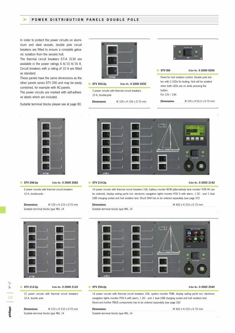
STV ISO Order-No.: 0 2000 0200
3 power circuits with thermal circuit breakers
10 A, double-pole
Dimensions W 105 x H 105 x D 70 mm
STV 203-2p Order-No.: 0 2000 2032
In order to protect the power circuits on alumi-nium and steel vessels, double pole circuit breakers are fitted to ensure a complete galva-nic isolation from the vessels hull. The thermal circuit breakers E-T-A 3130 areavailable in the power ratings 6 A/10 A/16 A.Circuit breakers with a rating of 10 A are fittedas standard. These panels have the same dimensions as theother panels series STV 200 and may be easilycombined, for example with AC-panels. The power circuits are marked with self-adhesi-ve labels which are included.
Suitable terminal blocks please see at page 80.
14 power circuits with thermal circuit breakers 10A, system monitor PSM, display sailing yacht incl. electronic
navigation lights monitor POS 6 with alarm, 1 DC - and 1 dual USB charging socket and hull isolation test.
Shunt and further PBUS components has to be ordered separately (see page 26)!
Dimensions W 420 x H 210 x D 70 mm
Suitable terminal blocks type RKL 14
14 power circuits with thermal circuit breakers 10A, battery monitor BCM (alternatively tank monitor TCM 4V can
be ordered), display sailing yacht incl. electronic navigation lights monitor POS 6 with alarm, 1 DC - and 1 dual
USB charging socket and hull isolation test. Shunt SHA has to be ordered separately (see page 37)!
Dimensions W 420 x H 210 x D 70 mm
Suitable terminal blocks type RKL 14
STV 254-2p Order-No.: 0 2002 2542
STV 214-2p Order-No.: 0 2002 2142
12 power circuits with thermal circuit breakers
10 A, double pole.
Dimensions W 210 x H 210 x D 70 mm
Suitable terminal blocks type RKL 14
6 power circuits with thermal circuit breakers
10 A, double-pole .
Dimensions W 105 x H 210 x D 70 mm
Suitable terminal blocks type RKL 14
STV 212-2p Order-No.: 0 2000 2122
STV 206-2p Order-No.: 0 2000 2062
k P O W E R D I S T R I B U T I O N P A N E L S D O U B L E P O L E
N° 17
11
NEW
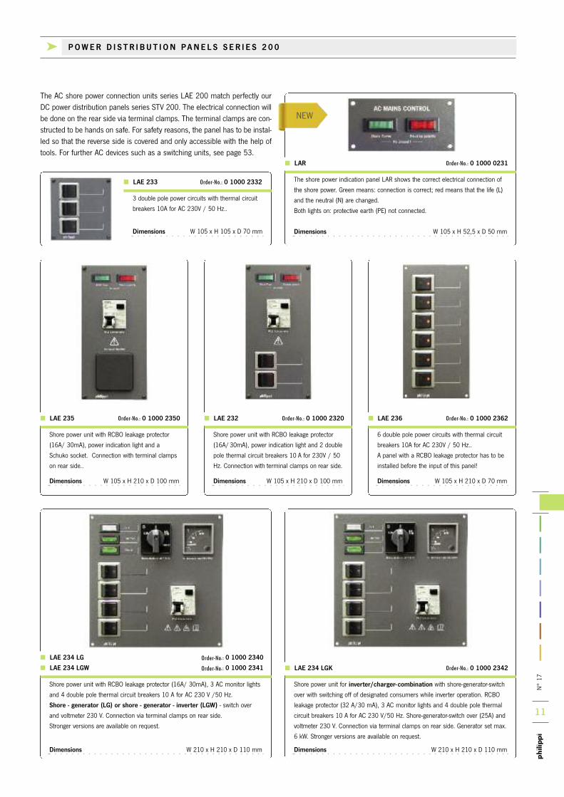
The AC shore power connection units series LAE 200 match perfectly ourDC power distribution panels series STV 200. The electrical connection willbe done on the rear side via terminal clamps. The terminal clamps are con-structed to be hands on safe. For safety reasons, the panel has to be instal-led so that the reverse side is covered and only accessible with the help oftools. For further AC devices such as a switching units, see page 53.
3 double pole power circuits with thermal circuit
breakers 10A for AC 230V / 50 Hz..
Dimensions W 105 x H 105 x D 70 mm
LAE 233 Order-No.: 0 1000 2332 The shore power indication panel LAR shows the correct electrical connection of
the shore power. Green means: connection is correct; red means that the life (L)
and the neutral (N) are changed.
Both lights on: protective earth (PE) not connected.
Dimensions W 105 x H 52,5 x D 50 mm
LAR Order-No.: 0 1000 0231
Shore power unit for inverter/charger-combination with shore-generator-switch
over with switching off of designated consumers while inverter operation. RCBO
leakage protector (32 A/30 mA), 3 AC monitor lights and 4 double pole thermal
circuit breakers 10 A for AC 230 V/50 Hz. Shore-generator-switch over (25A) and
voltmeter 230 V. Connection via terminal clamps on rear side. Generator set max.
6 kW. Stronger versions are available on request.
Dimensions W 210 x H 210 x D 110 mm
LAE 234 LGK Order-No.: 0 1000 2342
6 double pole power circuits with thermal circuit
breakers 10A for AC 230V / 50 Hz..
A panel with a RCBO leakage protector has to be
installed before the input of this panel!
Dimensions W 105 x H 210 x D 70 mm
LAE 236 Order-No.: 0 1000 2362
Shore power unit with RCBO leakage protector
(16A/30mA), power indication light and 2 double
pole thermal circuit breakers 10 A for 230V / 50
Hz. Connection with terminal clamps on rear side.
Dimensions W 105 x H 210 x D 100 mm
LAE 232 Order-No.: 0 1000 2320
Shore power unit with RCBO leakage protector
(16A/ 30mA), power indication light and a
Schuko socket. Connection with terminal clamps
on rear side..
Dimensions W 105 x H 210 x D 100 mm
LAE 235 Order-No.: 0 1000 2350
k POWER D I S T R I BU T I ON PANE L S S E R I E S 2 0 0
Shore power unit with RCBO leakage protector (16A/ 30mA), 3 AC monitor lights
and 4 double pole thermal circuit breakers 10 A for AC 230 V /50 Hz.
Shore - generator (LG) or shore - generator - inverter (LGW) - switch over
and voltmeter 230 V. Connection via terminal clamps on rear side.
Stronger versions are available on request.
Dimensions W 210 x H 210 x D 110 mm
LAE 234 LG Order-No.: 0 1000 2340
LAE 234 LGW Order-No.: 0 1000 2341
N° 17
12
Single pole DC: single pole rocker switch/thermal circuit breaker of compact design for snap-in panel mounting. Black with silver frame. Cut out dimensions 14,8 x 34,2 mm, Width 18 mm. Rated voltage DC 30 V, Power consumption of the LED: 0,7 mA at 12 V
Circuit breakers available ex stock
3130-F11B-K7T1-W29AG3-2A Order-No.: 1 3130 2002
3130-F11B-K7T1-W29AG3-6A Order-No.: 1 3130 2006
3130-F11B-K7T1-W29AG3-10A Order-No.: 1 3130 2010
3130-F11B-K7T1-W29AG3-16A Order-No.: 1 3130 2016
3130-F11B-K7T1-W29AG3-20A Order-No.: 1 3130 2020
3130-F11B-L7T1-U29AG3-10A (Push button) Order-No.: 1 3130 4010
3130-F11B-K7T1-W29AG3-30A Order-No.: 1 3130 2030
(30 A: width like double pole version!)
Double pole DC: double pole rocker switch/thermal circuit breaker. Cut out dimensions 26,3 x 34,2 mm, Width 29,3mm, Rated voltage DC 30V.Current consumption of the LED: 0,7 mA at 12 V.
3130-F12B-S2T1-W29AG3-6A Order-No.: 1 3131 2006
3130-F12B-S2T1-W29AG3--10A Order-No.: 1 3131 2010
3130-F12B-S2T1-W29AG3--16A Order-No.: 1 3131 2016
3130-F12B-S2T1-U29AG3-10A (Push button) Order-No.: 1 3131 4010
Double pole AC 230 V: double pole rocker switch/thermal circuit breaker.
3130-F12B-S2T1-W24AR7-6A Order-No.: 1 3130 5006
3130-F12B-S2T1-W24AR7-10A Order-No.: 1 3130 5010
3130-F12B-S2T1-W24AR7-16A Order-No.: 1 3130 5016
3130-F15B-L7T1-W24AR7-20A Order-No.: 1 3130 5020
E-T-A 3130
k THERMAL C I RCU I T B R E AKERS
Voltmeter DC
SQB 8-16V Order-No.: 6 0490 0816
SQB 16-32V Order-No.: 6 0490 1632
Tank gauge (DC 10-30V) for TGT/TGW
SQB Water (10-180W) No.: 6 0490 9182
SQB Fuel (10-180W) No.: 6 0490 9183
Ammeter DC (internal/external shunt)
SQB 0-40A (internal) Order-No.: 6 0491 0040
SQB 0-40A/60mV Order-No.: 6 0492 0040
SQB 0-60A/60mV Order-No.: 6 0492 0060
Shunt 40 A/60 mV Order-No.: 7 3060 0040
Shunt 60 A/60 mV Order-No.: 7 3060 0060
Voltmeter AC (without illumination)
SQB 250V (AC) Order-No.: 6 0495 0250
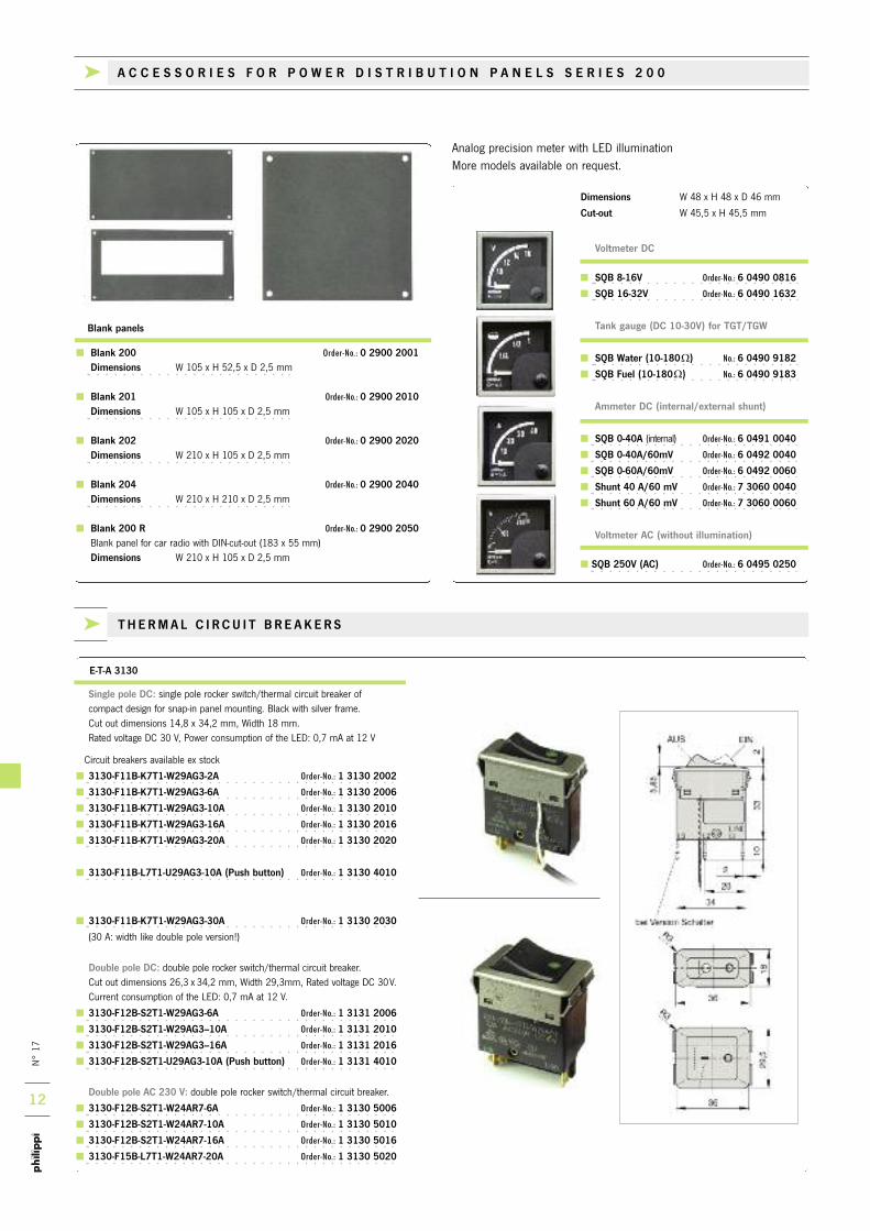
Blank 200 Order-No.: 0 2900 2001Dimensions W 105 x H 52,5 x D 2,5 mm
Blank 201 Order-No.: 0 2900 2010Dimensions W 105 x H 105 x D 2,5 mm
Blank 202 Order-No.: 0 2900 2020Dimensions W 210 x H 105 x D 2,5 mm
Blank 204 Order-No.: 0 2900 2040Dimensions W 210 x H 210 x D 2,5 mm
Blank 200 R Order-No.: 0 2900 2050Blank panel for car radio with DIN-cut-out (183 x 55 mm) Dimensions W 210 x H 105 x D 2,5 mm
Blank panels
Analog precision meter with LED illumination More models available on request.
Dimensions W 48 x H 48 x D 46 mm
Cut-out W 45,5 x H 45,5 mm
k A C C E S S O R I E S F O R P O W E R D I S T R I B U T I O N P A N E L S S E R I E S 2 0 0
N° 17
13
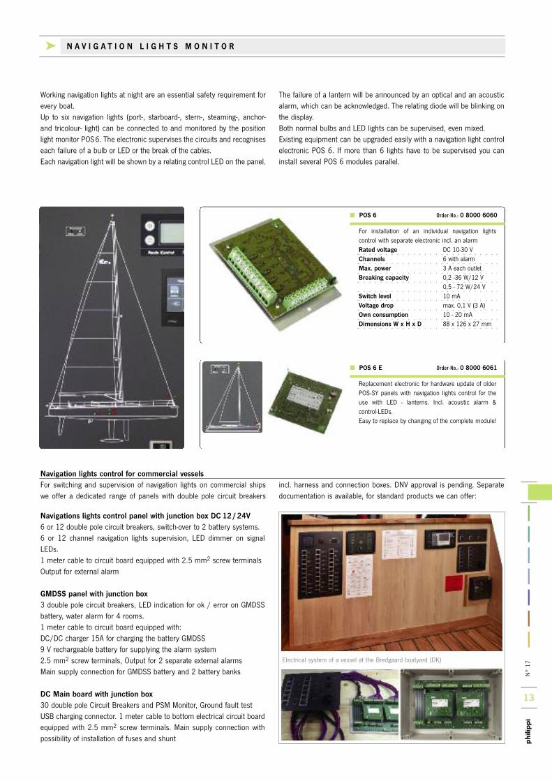
Electrical system of a vessel at the Bredgaard boatyard (DK)
For switching and supervision of navigation lights on commercial shipswe offer a dedicated range of panels with double pole circuit breakers
incl. harness and connection boxes. DNV approval is pending. Separatedocumentation is available, for standard products we can offer:
Navigation lights control for commercial vessels
Navigations lights control panel with junction box DC 12/24V6 or 12 double pole circuit breakers, switch-over to 2 battery systems. 6 or 12 channel navigation lights supervision, LED dimmer on signalLEDs. 1 meter cable to circuit board equipped with 2.5 mm2 screw terminalsOutput for external alarm
GMDSS panel with junction box3 double pole circuit breakers, LED indication for ok / error on GMDSSbattery, water alarm for 4 rooms.1 meter cable to circuit board equipped with:DC/DC charger 15A for charging the battery GMDSS9 V rechargeable battery for supplying the alarm system2.5 mm2 screw terminals, Output for 2 separate external alarmsMain supply connection for GMDSS battery and 2 battery banks
DC Main board with junction box30 double pole Circuit Breakers and PSM Monitor, Ground fault testUSB charging connector. 1 meter cable to bottom electrical circuit boardequipped with 2.5 mm2 screw terminals. Main supply connection withpossibility of installation of fuses and shunt
Working navigation lights at night are an essential safety requirement forevery boat.Up to six navigation lights (port-, starboard-, stern-, steaming-, anchor-and tricolour- light) can be connected to and monitored by the positionlight monitor POS6. The electronic supervises the circuits and recogniseseach failure of a bulb or LED or the break of the cables.Each navigation light will be shown by a relating control LED on the panel.
The failure of a lantern will be announced by an optical and an acousticalarm, which can be acknowledged. The relating diode will be blinking onthe display. Both normal bulbs and LED lights can be supervised, even mixed.Existing equipment can be upgraded easily with a navigation light controlelectronic POS 6. If more than 6 lights have to be supervised you caninstall several POS 6 modules parallel.
For installation of an individual navigation lights control with separate electronic incl. an alarmRated voltage DC 10-30 VChannels 6 with alarmMax. power 3 A each outletBreaking capacity 0,2 -36 W/12 V
0,5 - 72 W/24 VSwitch level 10 mAVoltage drop max. 0,1 V (3 A)Own consumption 10 - 20 mADimensions W x H x D 88 x 126 x 27 mm
Replacement electronic for hardware update of olderPOS-SY panels with navigation lights control for theuse with LED - lanterns. Incl. acoustic alarm & control-LEDs. Easy to replace by changing of the complete module!
POS 6 Order-No.: 0 8000 6060
POS 6 E Order-No.: 0 8000 6061
k N A V I G A T I O N L I G H T S M O N I T O R

N° 17
14
Top: before refit Bottom: after refit
Before refit After refit
Are you planning to build a new boat? Maybe just refit the one you have?When it comes to planning electrical wiring allow us to be your guide! Wehave decades of experience on electrical systems aboard yachts and spor-ting boats. With our extensive variety of products, we are sure to simplify all your electrical needs. You can be sure toreceive complete systems (plan & components) with the guarantee thatall parts received fit with each other.Since we work hand in hand with workingcrews of the boating industry, our productsremain up-to date including construction stan-dards and laws.
A central part of this planning is the produc-tion of special, individual switchgear. Forexample, switch panels for a current supply ofDC 12V /24V or a system voltage of AC230V/400V. Engine panels, switch plates forexternal areas and for larger 230V systems,we plan and produce complete control boxes.
Based on the technic of our power distribution panels and shore connec-tion units, the diagram presents a special version of switch gear as wellas instrument panels for external readings. Tabelled through a process ofscreen printing, illuminated letters, or self adhesive labels. It is possible to
print the outline of a customers yacht on theelectronic monitor panel.
We supply instrument panels in special cus-tom production to all dimensions, forms andcolour variations. Complete systems ready tobe installed consisting of
Shore power connection Distribution switch circuits Analogue gauges/ digital monitors
for batteries, tanks, battery chargers Sockets and switches Cut-out for special components
On our websitewww.philippi-online.de
you can download a questionnaire
In order to submit a quotation as well as for the design and manufactureof these circuit distribution panels we require exact details regarding therequirement on board.
k CUS TOM MADE PANE L S

N° 17
15
The navigation lights electronic POS 6 supervises up to 6 navigationlight circuits and recognises each failure of a bulb or LED or the breakof the cables.Each navigation light will be shown by a relating control LED on thepanel. The failure of a lantern will be announced by an optical and anacoustic alarm, which can be acknowledged. The relating diode will beblinking on the display. Both normal bulbs and LED lights can be supervised, even mixed.
SERIES 100
Power distribution switch panels in a build-up system for individual switching installations for ship's supply. Standard circuit breakers with
a nominal power rating of 8A are fitted. Circuit breakers with nominal power rating of 4A/6A/8A/10A/12A/16A may be fitted upon
request or supplied for later fitting. STKZ self-adhesive labels (165 per page) are included. The power distribution unit is supplied wired for
12V/24V with the relevant cable diameter. The connection is made with flat spade terminals 6.3 mm on the back of the unit.
The dimensions of the power distribution panels
are matched to each other to allow the choice
of horizontal or vertical combination.
Set of labels “STKZ” Self-adhesive labels will be provided
(see page 19)
Circuit breakers with nominal powerrating of
4A/6A/8A/10A/12A/16A maybe easy exchanged later on
The connection is made with flat spadeterminals 6.3 mm on the rear side of
the unit
k P O W E R D I S T R I B U T I O N P A N E L S S E R I E S 1 0 0

N° 17
16
NEW
1 power circuit with thermic circuit breaker (8 A),lamp diode display, rocker switch.
Dimensions W 110 x H 36,2 x D 70 mm
STV 101 Order-No.: 0 2000 1010
3 power circuits with thermal circuit breakers (8 A),lamp diodes display, rocker switches.
Dimensions W 110 x H 72,5 x D 70 mmSuitable terminal blocks type RKL 10
STV 103 Order-No.: 0 2000 1030
6 power circuits with thermal circuit breakers (8 A), lamp diodes display, rocker switches.
Dimensions W 110 x H 117 x D 70 mmSuitable terminal blocks type RKL 10
5 power circuits with thermal circuit breakers(8A), lamp diodes display, rocker switches, DC- and dual USB charging socket.
Dimensions W 110 x H 145 x D 70 mm Suitable terminal blocks type RKL 10.
STV 106 Order-No.: 0 2000 1060
STV 105 Order-No.: 0 2000 1050
Voltmeter with switch over for service- und starterbattery as addition to switch boards series STV 100.
Dimensions W 110 x H 72,5 x D 80 mm
PV -12 V Order-No.: 0 2801 0120
PV -24 V Order-No.: 0 2802 0120
10 power circuits with thermal circuit breakers (8 A),lamp diodes display, rocker switches.
Dimensions W 110 x H 180 x D 70 mmSuitable terminal blocks type RKL 10
STV 110 Order-No.: 0 2000 1100
Recommended wires cross sectionfor consumers supply lines
Circuit breaker A 6 10 16 20
Wire mm2 1,0 1,5 2,5 4
6 power circuits with thermal circuit breakers(8A), lamp diodes display, rocker switches andprotected small socket with protective cap.
Dimensions W 110 x H 145 x D 70 mm Suitable terminal blocks type RKL 10.
8 power circuits with thermal circuit breakers (8 A), lamp diodes display, rocker switches.
Dimensions W 110 x H 145 x D 70 mmSuitable terminal blocks type RKL 10
STV 106/1 Order-No.: 0 2000 1061 STV 108 Order-No.: 0 2000 1080
k P O W E R D I S T R I B U T I O N P A N E L S S E R I E S 1 0 0
N° 17
17
Display of up to 3 tanks. Differenttank symbols can be selected.
All setup adjustments can be done inthe monitor display directly.
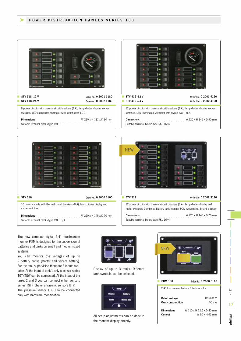
12 power circuits with thermal circuit breakers (8 A), lamp diodes display and
rocker switches. Combined battery tank monitor PDM (2xvoltage, 3x tank display)
Dimensions W 220 x H 145 x D 70 mm
Suitable terminal blocks type RKL 16/4
STV 312 Order-No.: 0 2002 3120
2,4“ touchscreen battery / tank monitor
Rated voltage DC 8-32 VOwn consumption 50 mA
Dimensions W 110 x H 72,5 x D 40 mmCut-out W 90 x H 62 mm
The new compact digital 2,4“ touchscreenmonitor PDM is designed for the supervision ofbatteries and tanks on small and medium sizedsystems.You can monitor the voltages of up to 2 battery banks (starter and service battery). For the tank supervision there are 3 inputs avai-lable. At the input of tank 1 only a sensor seriesTGT/TGW can be connected. At the input of thetanks 2 and 3 you can connect either sensorsseries TGT/TGW or ultrasonic sensors UTV. The pressure sensor TDS can be connectedonly with hardware modification.
PDM 100 Order-No.: 0 2000 0110
16 power circuits with thermal circuit breakers (8 A), lamp diodes display and rocker switches.
Dimensions W 220 x H 145 x D 70 mm
Suitable terminal blocks type RKL 16/4
STV 316 Order-No.: 0 2000 3160
8 power circuits with thermal circuit breakers (8 A), lamp diodes display, rocker
switches, LED illuminated voltmeter with switch over 1-0-2.
Dimensions W 220 x H 117 x D 90 mm
Suitable terminal blocks type RKL 10
STV 118 -12 V Order-No.: 0 2001 1180
STV 118 -24 V Order-No.: 0 2002 1180
12 power circuits with thermal circuit breakers (8 A), lamp diodes display, rocker
switches, LED illuminated voltmeter with switch over 1-0-2.
Dimensions W 220 x H 145 x D 90 mm
Suitable terminal blocks type RKL 16/4
STV 412 -12 V Order-No.: 0 2001 4120
STV 412 -24 V Order-No.: 0 2002 4120
k P O W E R D I S T R I B U T I O N P A N E L S S E R I E S 1 0 0
NEW
NEW
N° 17
18
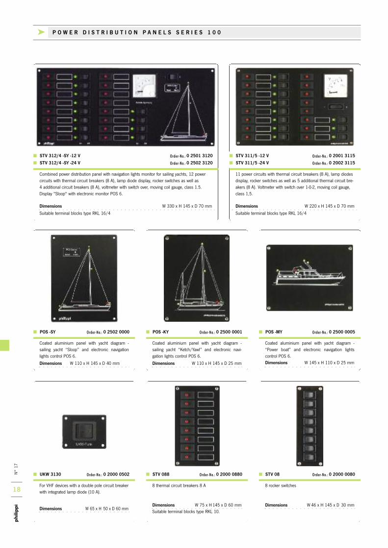
STV 088 Order-No.: 0 2000 0880 STV 08 Order-No.: 0 2000 0080
POS -MY Order-No.: 0 2500 0005 POS -KY Order-No.: 0 2500 0001 POS -SY Order-No.: 0 2502 0000
Combined power distribution panel with navigation lights monitor for sailing yachts, 12 powercircuits with thermal circuit breakers (8 A), lamp diode display, rocker switches as well as 4 additional circuit breakers (8 A), voltmeter with switch over, moving coil gauge, class 1.5.Display "Sloop" with electronic monitor POS 6.
Dimensions W 330 x H 145 x D 70 mm
Suitable terminal blocks type RKL 16/4
STV 312/4 -SY -12 V Order-No.: 0 2501 3120
STV 312/4 -SY -24 V Order-No.: 0 2502 3120
For VHF devices with a double pole circuit breakerwith integrated lamp diode (10 A).
Dimensions W 65 x H 50 x D 60 mm
UKW 3130 Order-No.: 0 2000 0502
11 power circuits with thermal circuit breakers (8 A), lamp diodesdisplay, rocker switches as well as 5 additional thermal circuit bre-akers (8 A). Voltmeter with switch over 1-0-2, moving coil gauge,class 1,5.
Dimensions W 220 x H 145 x D 70 mm
Suitable terminal blocks type RKL 16/4
STV 311/5 -12 V Order-No.: 0 2001 3115
STV 311/5 -24 V Order-No.: 0 2002 3115
8 thermal circuit breakers 8 A
Dimensions W 75 x H 145 x D 60 mmSuitable terminal blocks type RKL 10.
8 rocker switches
Dimensions W46 x H 145 x D 30 mm
Coated aluminium panel with yacht diagram -“Power boat” and electronic navigation lights control POS 6.Dimensions W 145 x H 110 x D 25 mm
Coated aluminium panel with yacht diagram - sailing yacht “Ketch/Yawl” and electronic navi-gation lights control POS 6.
Dimensions W 110 x H 145 x D 25 mm
Coated aluminium panel with yacht diagram - sailing yacht “Sloop” and electronic navigationlights control POS 6.
Dimensions W 110 x H 145 x D 40 mm
k P O W E R D I S T R I B U T I O N P A N E L S S E R I E S 1 0 0

AUS
ø 4,2
11
34,5
19
N° 17
19
Blank panels for covering larger cut-outs and individual panels. Plastic-coated aluminium board with 4 mounting holes.
Blank panel Leer 103 Order-No.: 0 2900 1030Dimensions W 110 x H 72,5 x D 2 mm
Blank panel Leer 108 Order-No.: 0 2900 1080Dimensions W 110 x H 145 x D 2 mm
Blank panel Leer 110 Order-No.: 0 2900 5100Dimensions W 110 x H 180 x D 2 mm
Blank panel Leer 316 Order-No.: 0 2900 3160Dimensions W 220 x H 145 x D 2 mm
SL 9 rot (AC 230 V) Order No.: 6 0009 0557LED 10 mm
E-T-A 1140-F114-P1-M1
Blank panelsPower circuit labels
LED 5 mmLED 3 mm
All information about the labels listed hereon www.philippi-online.de
Power circuit labels for individual power circuits mounted on panels. Self adhesivewatertight vinyl foil. 165 different signs in languages German, Dutch, English,French, Dansk, Polish, Italian (only 62 labels). Dimensions 27 x 8 mm.
STKZ - D Order-No.: 0 2900 1650
STKZ - NL Order-No.: 0 2900 1651
STKZ - GB Order-No.: 0 2900 1652
STKZ - I Order-No.: 0 2900 1653
STKZ - DK Order-No.: 0 2900 1655
STKZ - PL Order-No.: 0 2900 1656
STKZ - F Order-No.: 0 2900 1657
k ACCES SOR I E S FOR POWER D I S T R I BU T I ON PANE L S S E R I E S 1 0 0
Single pole thermal circuit breaker with push-to-reset, failsafe, trip-free (EN 60934). Snap-in type. Cut out measurement:22 x 11.3 mm. Rated voltage DC 48 V, AC 240 V. Current ratings 4...16 A
Circuit breakers available ex stock
ETA 1140-F114-P1-M1-4A Order No.: 1 1140 0004
ETA 1140-F114-P1-M1-6A Order No.: 1 1140 0006
ETA 1140-F114-P1-M1-8A Order No.: 1 1140 0008
ETA 1140-F114-P1-M1-10A Order No.: 1 1140 0010
ETA 1140-F114-P1-M1-12A Order No.: 1 1140 0012
ETA 1140-F114-P1-M1-16A Order No.: 1 1140 0016
Signal lamp for AC 230V/50Hz, cable length:20 cm. Fitting hole l 8 mm.
Lamp diodes with minimal power consumption of 7 mA. (12V) / 16 mA (24V). Connectabledirectly to 12/24V (DC 30V). Fitting hole: l 10 mm
LED 10 mm, red Order No.: 6 0005 1000
LED 10 mm, yellow Order No.: 6 0005 1010
LED 10 mm, green Order No.: 6 0005 1020
Lamp diodes with minimal power consumption of 4 mA (12 V) / 8 mA (24 V). Connectable directlyto 12/24V (DC 30V). Fitting hole: l 6,2 mm
LED 5 mm, red Order No.: 6 0005 0600
LED 5 mm, yellow Order No.: 6 0005 0610
LED 5 mm, green Order No.: 6 0005 0620
Lamp diodes with minimal power consumption of6 mA (12V) and 12mA (24V). Connectable direct-ly to 12/24V (DC 30V). Fitting hole: l 4,2 mm
LED 3 mm, red Order No.: 7 0000 3050
LED 3 mm, yellow Order No.: 7 0000 3051
LED 3 mm, green Order No.: 7 0000 3052
N° 17
20
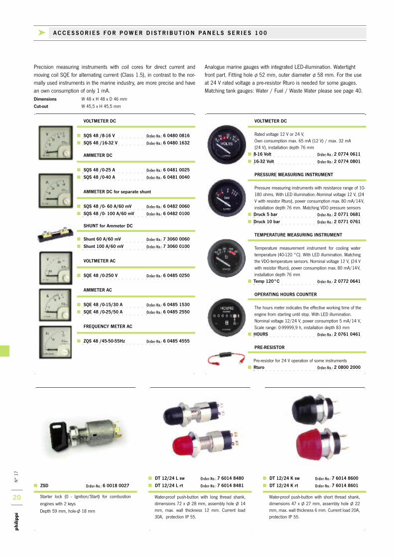
DT 12/24 K sw Order-No.: 7 6014 8600
DT 12/24 K rt Order-No.: 7 6014 8601
DT 12/24 L sw Order-No.: 7 6014 8480
DT 12/24 L rt Order-No.: 7 6014 8481 ZSD Order-No.: 6 0018 0027
Starter lock (0 - Ignition/Start) for combustion
engines with 2 keys
Depth 59 mm, hole-l 18 mm
Precision measuring instruments with coil cores for direct current andmoving coil SQE for alternating current (Class 1.5), in contrast to the nor-mally used instruments in the marine industry, are more precise and havean own consumption of only 1 mA.Dimensions W 48 x H 48 x D 46 mm
Cut-out W 45,5 x H 45,5 mm
Analogue marine gauges with integrated LED-illumination. Watertightfront part. Fitting hole l 52 mm, outer diameter l 58 mm. For the useat 24 V rated voltage a pre-resistor Rturo is needed for some gauges.Matching tank gauges: Water / Fuel / Waste Water please see page 40.
VOLTMETER DC
SQS 48 /8-16 V Order-No.: 6 0480 0816
SQS 48 /16-32 V Order-No.: 6 0480 1632
AMMETER DC
SQS 48 /0-25 A Order-No.: 6 0481 0025
SQS 48 /0-40 A Order-No.: 6 0481 0040
AMMETER DC for separate shunt
SQS 48 /0- 60 A/60 mV Order-No.: 6 0482 0060
SQS 48 /0- 100 A/60 mV Order-No.: 6 0482 0100
SHUNT for Ammeter DC
Shunt 60 A/60 mV Order-No.: 7 3060 0060
Shunt 100 A/60 mV Order-No.: 7 3060 0100
VOLTMETER AC
SQE 48 /0-250 V Order-No.: 6 0485 0250
AMMETER AC
SQE 48 /0-15/30 A Order-No.: 6 0485 1530
SQE 48 /0-25/50 A Order-No.: 6 0485 2550
FREQUENCY METER AC
ZQS 48 /45-50-55Hz Order-No.: 6 0485 4555
VOLTMETER DC
Rated voltage 12 V or 24 V, Own consumption max. 65 mA (12 V) / max. 32 mA (24 V), installation depth 76 mm
8-16 Volt Order-No.: 2 0774 0611
16-32 Volt Order-No.: 2 0774 0801
PRESSURE MEASURING INSTRUMENT
Pressure measuring instruments with resistance range of 10-180 ohms. With LED illumination.-Nominal voltage 12 V, (24V with resistor Rturo), power consumption max. 80 mA/14V,installation depth 76 mm. Matching VDO pressure sensors
Druck 5 bar Order-No.: 2 0771 0681
Druck 10 bar Order-No.: 2 0771 0761
TEMPERATURE MEASURING INSTRUMENT
Temperature measurement instrument for cooling watertemperature (40-120 °C). With LED illumination. Matchingthe VDO-temperature sensors. Nominal voltage 12 V, (24 Vwith resistor Rturo), power consumption max. 80 mA/14V,installation depth 76 mm
Temp 120°C Order-No.: 2 0772 0641
OPERATING HOURS COUNTER
The hours meter indicates the effective working time of theengine from starting until stop. With LED illumination.Nominal voltage 12/24 V, power consumption 5 mA/14 V,Scale range: 0-99999,9 h, installation depth 83 mm
HOURS Order-No.: 2 0761 0461
PRE-RESISTOR
Pre-resistor for 24 V operation of some instruments Rturo Order-No.: 2 0800 2000
Water-proof push-button with short thread shank,dimensions 47 x l 27 mm, assembly hole l 22mm, max. wall thickness 6 mm. Current load 20A,protection IP 55.
Water-proof push-button with long thread shank,dimensions 72 x l 28 mm, assembly hole l 14mm, max. wall thickness 12 mm. Current load30A, protection IP 55.
k ACCES SOR I E S FOR POWER D I S T R I BU T I ON PANE L S S E R I E S 1 0 0
N° 17
21
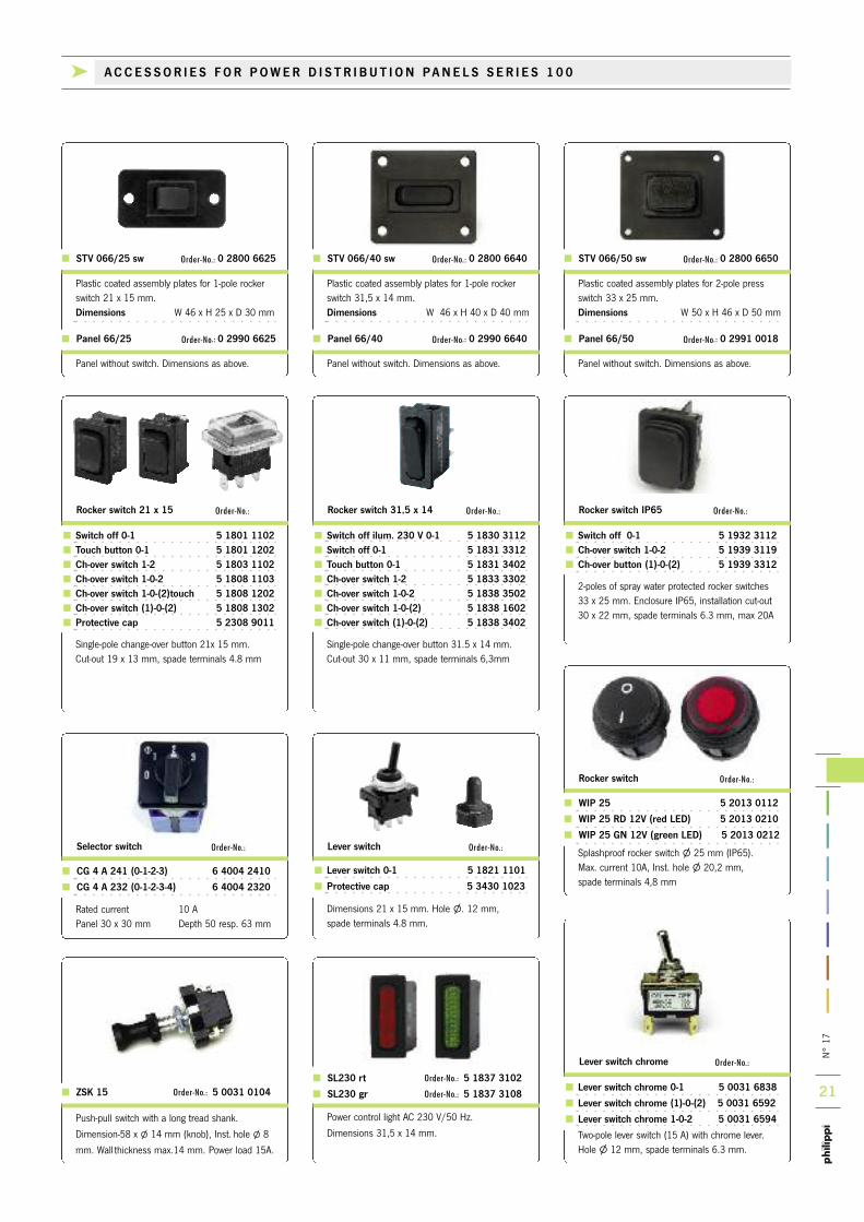
Lever switch 0-1 5 1821 1101
Protective cap 5 3430 1023
Dimensions 21 x 15 mm. Hole l. 12 mm, spade terminals 4.8 mm.
Power control light AC 230 V/50 Hz.
Dimensions 31,5 x 14 mm.
SL230 rt Order-No.: 5 1837 3102
SL230 gr Order-No.: 5 1837 3108
Splashproof rocker switch l 25 mm (IP65). Max. current 10A, Inst. hole l 20,2 mm, spade terminals 4,8 mm
Rocker switch Order-No.:
WIP 25 5 2013 0112
WIP 25 RD 12V (red LED) 5 2013 0210
WIP 25 GN 12V (green LED) 5 2013 0212Lever switch Order-No.:
Panel without switch. Dimensions as above.
Panel 66/50 Order-No.: 0 2991 0018
Panel without switch. Dimensions as above.
Panel 66/40 Order-No.: 0 2990 6640
Panel without switch. Dimensions as above.
Panel 66/25 Order-No.: 0 2990 6625
ZSK 15 Order-No.: 5 0031 0104
Push-pull switch with a long tread shank.
Dimension-58 x l 14 mm (knob), Inst. hole l 8
mm. Wall thickness max.14 mm. Power load 15A.
Lever switch chrome 0-1 5 0031 6838
Lever switch chrome (1)-0-(2) 5 0031 6592
Lever switch chrome 1-0-2 5 0031 6594
Two-pole lever switch (15 A) with chrome lever.Hole l 12 mm, spade terminals 6.3 mm.
Lever switch chrome Order-No.:
Rated current 10 APanel 30 x 30 mm Depth 50 resp. 63 mm
Selector switch Order-No.:
CG 4 A 241 (0-1-2-3) 6 4004 2410
CG 4 A 232 (0-1-2-3-4) 6 4004 2320
Rocker switch IP65 Order-No.:
Switch off 0-1 5 1932 3112 Ch-over switch 1-0-2 5 1939 3119 Ch-over button (1)-0-(2) 5 1939 3312
2-poles of spray water protected rocker switches 33 x 25 mm. Enclosure IP65, installation cut-out 30 x 22 mm, spade terminals 6.3 mm, max 20A
Switch off ilum. 230 V 0-1 5 1830 3112 Switch off 0-1 5 1831 3312 Touch button 0-1 5 1831 3402 Ch-over switch 1-2 5 1833 3302 Ch-over switch 1-0-2 5 1838 3502 Ch-over switch 1-0-(2) 5 1838 1602 Ch-over switch (1)-0-(2) 5 1838 3402
Single-pole change-over button 31.5 x 14 mm. Cut-out 30 x 11 mm, spade terminals 6,3mm
Switch off 0-1 5 1801 1102 Touch button 0-1 5 1801 1202 Ch-over switch 1-2 5 1803 1102 Ch-over switch 1-0-2 5 1808 1103 Ch-over switch 1-0-(2)touch 5 1808 1202 Ch-over switch (1)-0-(2) 5 1808 1302 Protective cap 5 2308 9011
Single-pole change-over button 21x 15 mm. Cut-out 19 x 13 mm, spade terminals 4.8 mm
Rocker switch 31,5 x 14 Order-No.:Rocker switch 21 x 15 Order-No.:
Plastic coated assembly plates for 2-pole pressswitch 33 x 25 mm.Dimensions W 50 x H 46 x D 50 mm
STV 066/50 sw Order-No.: 0 2800 6650
Plastic coated assembly plates for 1-pole rockerswitch 31,5 x 14 mm. Dimensions W 46 x H 40 x D 40 mm
STV 066/40 sw Order-No.: 0 2800 6640
Plastic coated assembly plates for 1-pole rockerswitch 21 x 15 mm. Dimensions W 46 x H 25 x D 30 mm
STV 066/25 sw Order-No.: 0 2800 6625
k ACCES SOR I E S FOR POWER D I S T R I BU T I ON PANE L S S E R I E S 1 0 0
N° 17
22
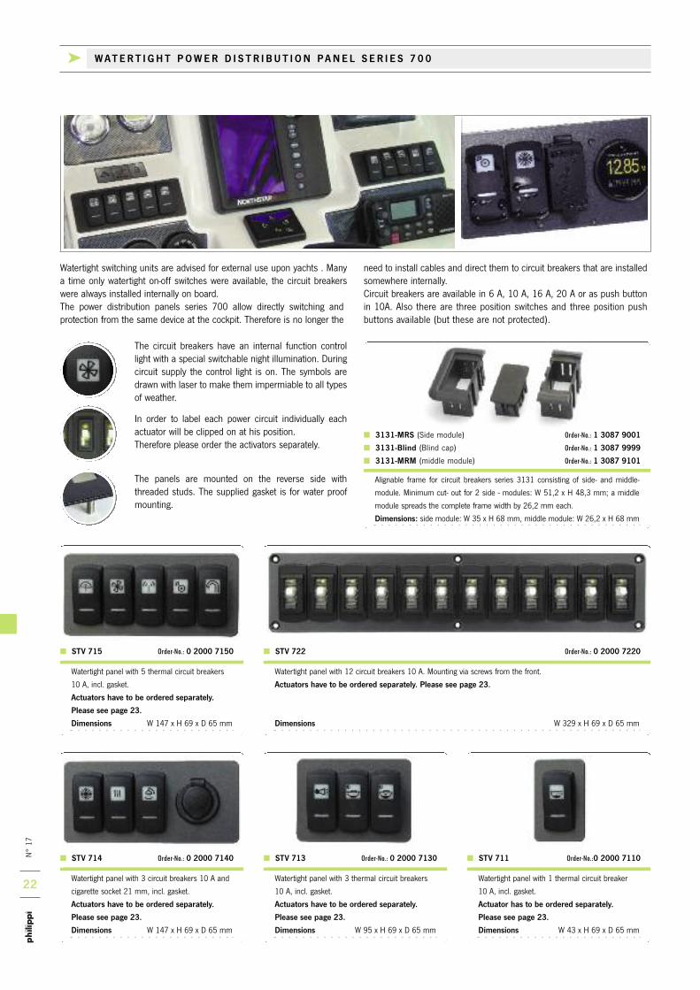
Alignable frame for circuit breakers series 3131 consisting of side- and middle-
module. Minimum cut- out for 2 side - modules: W 51,2 x H 48,3 mm; a middle
module spreads the complete frame width by 26,2 mm each.
Dimensions: side module: W 35 x H 68 mm, middle module: W 26,2 x H 68 mm
3131-MRS (Side module) Order-No.: 1 3087 9001
3131-Blind (Blind cap) Order-No.: 1 3087 9999
3131-MRM (middle module) Order-No.: 1 3087 9101
Watertight panel with 12 circuit breakers 10 A. Mounting via screws from the front.
Actuators have to be ordered separately. Please see page 23.
Dimensions W 329 x H 69 x D 65 mm
STV 722 Order-No.: 0 2000 7220
Watertight panel with 5 thermal circuit breakers
10 A, incl. gasket.
Actuators have to be ordered separately.
Please see page 23.
Dimensions W 147 x H 69 x D 65 mm
Watertight panel with 3 circuit breakers 10 A and
cigarette socket 21 mm, incl. gasket.
Actuators have to be ordered separately.
Please see page 23.
Dimensions W 147 x H 69 x D 65 mm
Watertight panel with 3 thermal circuit breakers
10 A, incl. gasket.
Actuators have to be ordered separately.
Please see page 23.
Dimensions W 95 x H 69 x D 65 mm
Watertight panel with 1 thermal circuit breaker
10 A, incl. gasket.
Actuator has to be ordered separately.
Please see page 23.
Dimensions W 43 x H 69 x D 65 mm
STV 715 Order-No.: 0 2000 7150
STV 714 Order-No.: 0 2000 7140 STV 713 Order-No.: 0 2000 7130 STV 711 Order-No.:0 2000 7110
Watertight switching units are advised for external use upon yachts . Manya time only watertight on-off switches were available, the circuit breakerswere always installed internally on board.The power distribution panels series 700 allow directly switching and protection from the same device at the cockpit. Therefore is no longer the
need to install cables and direct them to circuit breakers that are installedsomewhere internally. Circuit breakers are available in 6 A, 10 A, 16 A, 20 A or as push buttonin 10A. Also there are three position switches and three position pushbuttons available (but these are not protected).
The circuit breakers have an internal function controllight with a special switchable night illumination. Duringcircuit supply the control light is on. The symbols aredrawn with laser to make them impermiable to all typesof weather.
In order to label each power circuit individually eachactuator will be clipped on at his position. Therefore please order the activators separately.
The panels are mounted on the reverse side with threaded studs. The supplied gasket is for water proofmounting.
k WATER T I GHT POWER D I S T R I BU T I ON PANE L S E R I E S 7 0 0

N° 17
23
NEWNEW
Monitors DC voltage on a bright, waterproof,
daylight readable OLED screen.
The front is watertight IP66.
•8-36 V DC, resolution 0,01 V, max. 13 mA
•Reverse polarity protected
•Mounting hole Ø 29 mm, outer-Ø 40 mm
Watertight buzzer for 12 V / 24 V, IP68. Rotating
bezel adjusts alarm volume in a wide range.
•Operating current: 5 mA (12 V) / 12 mA (24 V)
•Aperture hole: Ø 29 mm
•Outer diameter: 35 mm
SUM 29 Order-No.: 7 0010 1070 USD EK Order-No.: 7 0010 1039
Spray nozzle Order-No.: 1 2222 8820
Searchlight Order-No.: 1 2222 8823
Autopilot Order-No.: 1 2222 8824
Trim tab Order-No.: 1 2222 8825
Sailing boat position lights Order-No.: 1 2222 8827
Sailing boat cock pit illumination Order-No.: 1 2222 8828
Sailing boat deck illumination Order-No.: 1 2222 8829
Sailing boat anchor light Order-No.: 1 2222 8830
Socket Order-No.: 1 2222 8841
Blue light Order-No.: 1 2222 8842
Underwater illumination Order-No.: 1 2222 8870
Bimini illumination Order-No.: 1 2222 8871
Step illumination Order-No.: 1 2222 8872
Stern flap Order-No.: 1 2222 8873
Main sail Order-No.: 1 2222 8874
Winch Order-No.: 1 2222 8875
ON / OFF Order-No.: 1 2222 8877
Lift Order-No.: 1 2222 8878
Seat inclination Order-No.: 1 2222 8879
Seat forwards/backwards Order-No.: 1 2222 8880
Neutral Order-No.: 1 2222 8201
Power boat interior illumination Order-No.: 1 2222 8801
Power boat anchor light Order-No.: 1 2222 8802
Power boat cockpit illumination Order-No.: 1 2222 8803
Power boat position lights Order-No.: 1 2222 8804
Power boat bow lantern Order-No.: 1 2222 8843
VHF Order-No.: 1 2222 8805
Refrigerator Order-No.: 1 2222 8806
Anchor winch control Order-No.: 1 2222 8807
Anchor winch up/down Order-No.: 1 2222 8844
Wind screen wiper Order-No.: 1 2222 8808
Bilge pump Order-No.: 1 2222 8809
Fresh water pump Order-No.: 1 2222 8810
Horn Order-No.: 1 2222 8811
Ventilation Order-No.: 1 2222 8812
Instruments illumination Order-No.: 1 2222 8813
Navigation instruments Order-No.: 1 2222 8814
Radio / Tuner Order-No.: 1 2222 8815
Heating system Order-No.: 1 2222 8816
Shower pump Order-No.: 1 2222 8817
Actuators for circuit breakers series E-T-A 3131 / STV700
Circuit breakers series E-T-A 3131
Snap in single pole on/off circuit breaker, water tight (IP 66) with overload protection
and LED control and nightlight Three position switches without protection (max. 20A)!
Cut-out dimensions:37 x 21.1mm Widh:24mm.
Rated voltage DC 10-30 V, Rated current 6...20 A. Delivery without actuator.
3131-AF1ET-0000O0-3Y2-6A Order-No.: 1 3135 1006
3131-AF1ET-0000O0-3Y2-10A Order-No.: 1 3135 1010
3131-AF1ET-0000O0-3Y2-16A Order-No.: 1 3135 1016
3131-AF1ET-0000O0-3Y2-20A Order-No.: 1 3135 1020
Circuit breaker push button function
3131-CF1ET-0000O0-3Y2-10A Order-No.: 1 3135 2010
Three position switch 1-0-2 without protection
3131-BF1NQ-0000O0-2Y2-20A Order-No.: 1 3135 3020
Three position push button (1)-0-(2) without protection
3131-DF1NQ-0000O0-2Y2-20A Order-No.: 1 3135 4020
MVD Order-No.: 7 0010 1733
Dual USB charger switch mount
•Input Voltage Range 9-32 V DC
•Maximum Output Current 4.8 A DC (total)
•Output Voltage 5 V DC ±5%
•Parasitic Current Draw 1 mA
k ACCES SOR I E S FOR POWER D I S T R I BU T I ON PANE L S S E R I E S 7 0 0
NEW

n°
17
24
Tank InterfaceCMT 2
System MonitorPSM
Battery Management-
Shunt SHCDigital SwitchingE-T-A PowerPlex
DC-BatteryMain Switch
FBC/TSC
DC-SwitchingInterface
CMR4
For the interconnection of the P-BUS components we use the watertightM12 connection system which is well known for industrial purposesunder the name Devicenet®. this connection system is also used by thenMEA2000® system, but please don`t connect them directly - due to different CAn-Bus systems and power supply you cannot connect the P-BUS and the nMEA2000® system with one backbone . only by usingthe nMEA2000®-bridge CBn it`s possible to interconnect them. in order to save valuable energy all connected P-BUS components will beswitched to standby mode if all PSM system monitors are in standbymode or switched off.
the PSM system monitor is the central indicating and operating deviceof the electrical system on board. it enables the monitoring and control-ling of all connected philippi PBUS compatible components and furthercomponents connected to PBUS - interfaces. the clear structure of thesystem monitor PSM provides an intuitive and logical operation via thetouchscreen.
the PBUS system design allows to connect more than one sys-tem monitor side by side to obtain information about tanks,
batteries, energy management and AC-power simulta-neously. Alternatively several PSM system monitors
may be installed on board at different locationsto obtain the required information independ-
ently of each other.
the combination of the system moni-tor PSM with a digital shunt SHC as bat-tery monitor for the main battery includingvoltage measurement for a starter battery canbe the first step for this new system. By fittingadditional shunts SHC for further batteries and/orother devices such as tank interfaces or switching interfaces it`s easy to extend the system to your desire. All further connections of PBUS components expand the system monitor PSM to a multifunctional monitor.
k S Y S T E M M O N I T O R P S M
P S M M o n i to r

n°
17
25
P - B U S
CAV FBC, TSC, EM-box SHL, ACE, EM-box
SHC, EM-box CMT 2 CMR 4, E-T-A PowerPlex
NMEA2000®
BridgeTemperatureInterface TPC
AC-InterfaceCAV
Battery ChargerACEEM-Box
Energy-ShuntSHL 312
BATTERY MONITOR
Apart from the current, voltage and capacity displaythe battery level is shown graphically. Further informa-tion as remaining time and statistics are available on
command. if you connect further shunts SHC thesystem monitor PSM can display all information of e.g.
the starter, bow or second service battery.
TANK MONITOR
Different kind of liquids are shown in different coloursindependently from the tank sensor. if the tank level
exceeds or falls below a given threshold the respectivetank will be displayed in red. the names and locations
of the tanks are adjustable individually.
ENERGY MONITOR DC
the ongoing charge or discharge currents of the sour-ces and loads are displayed in an energy scheme.Alternatively the energy up to now charged or usedcan be shown (e.g. the harvest of a solar panel per
season). there`s a sub menu for chargers which dis-plays their specific data and from where you
operate and change the settings.
MAIN SWITCH MONITOR
the battery main switches can be switched by key-press. An optional Pin code protects the systemagainst unauthorised use. the deep discharge protection of the batteries can be activated on
demand.
ENERGY MONITOR AC
the voltage and frequency of the connected sources,the active source and it`s power data will be displayed. there`s a sub menu for gensets and inverters whichshows specific information and from where you have
operational possibilities.
DIGITAL SWITCHING
the switching of consumers in a digital CAn bus system enables a comfortable operation from one
or more locations on the boat. By using the interfaceCMr you can dimm Prebit LED-lights without
interferences.
k S Y S T E M M O N I T O R P S M
n°
17
26
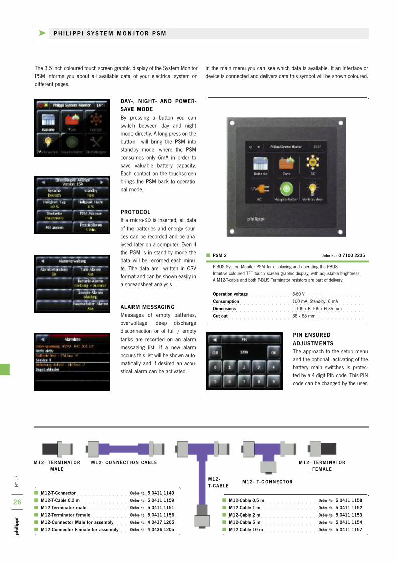
PIN ENSURED ADJUSTMENTSthe approach to the setup menuand the optional activating of thebattery main switches is protec-ted by a 4 digit Pin code. this Pincode can be changed by the user.
the 3,5 inch coloured touch screen graphic display of the System MonitorPSM informs you about all available data of your electrical system on different pages.
in the main menu you can see which data is available. if an interface or device is connected and delivers data this symbol will be shown coloured.
DAY-, NIGHT- AND POWER-SAVE MODEBy pressing a button you canswitch between day and nightmode directly. A long press on thebutton will bring the PSM intostandby mode, where the PSMconsumes only 6mA in order tosave valuable battery capacity.Each contact on the touchscreenbrings the PSM back to operatio-nal mode.
PROTOCOLif a micro-SD is inserted, all dataof the batteries and energy sour-ces can be recorded and be ana-lysed later on a computer. Even ifthe PSM is in stand-by mode thedata will be recorded each minu-te. the data are written in CSVformat and can be shown easily ina spreadsheet analysis.
ALARM MESSAGINGMessages of empty batteries,overvoltage, deep dischargedisconnection or of full / emptytanks are recorded on an alarmmessaging list. if a new alarmoccurs this list will be shown auto-matically and if desired an acou-stical alarm can be activated.
M12-Cable 0,5 m Order-No.: 5 0411 1158
M12-Cable 1 m Order-No.: 5 0411 1152
M12-Cable 2 m Order-No.: 5 0411 1153
M12-Cable 5 m Order-No.: 5 0411 1154
M12-Cable 10 m Order-No.: 5 0411 1157
P-BUS System Monitor PSM for displaying and operating the PBUS. intuitive coloured tFt touch screen graphic display, with adjustable brightness.A M12-t-cable and both P-BUS terminator resistors are part of delivery.
Operation voltage 8-60 V
Consumption 100 mA, Stand-by: 6 mA
Dimensions L 105 x B 105 x H 35 mm
Cut out 88 x 88 mm
M12- TERMINATORMALE
M12- TERMINATORFEMALE
M12- CONNECTION CABLE
M12- T- CONNECTORM12-T- CABLE
M12-T-Connector Order-No.: 5 0411 1149
M12-T-Cable 0,2 m Order-No.: 5 0411 1159
M12-Terminator male Order-No.: 5 0411 1151
M12-Terminator female Order-No.: 5 0411 1156
M12-Connector Male for assembly Order-No.: 4 0437 1205
M12-Connector Female for assembly Order-No.: 4 0436 1205
PSM 2 Order-No.: 0 7100 2235
k P H I L I P P I S Y S T E M M O N I T O R P S M
n°
17
27
MASTERBUSSTUDERNMEA2000®P-BUS P-BUS P-BUS
nEWnEW
nEW nEW nEW
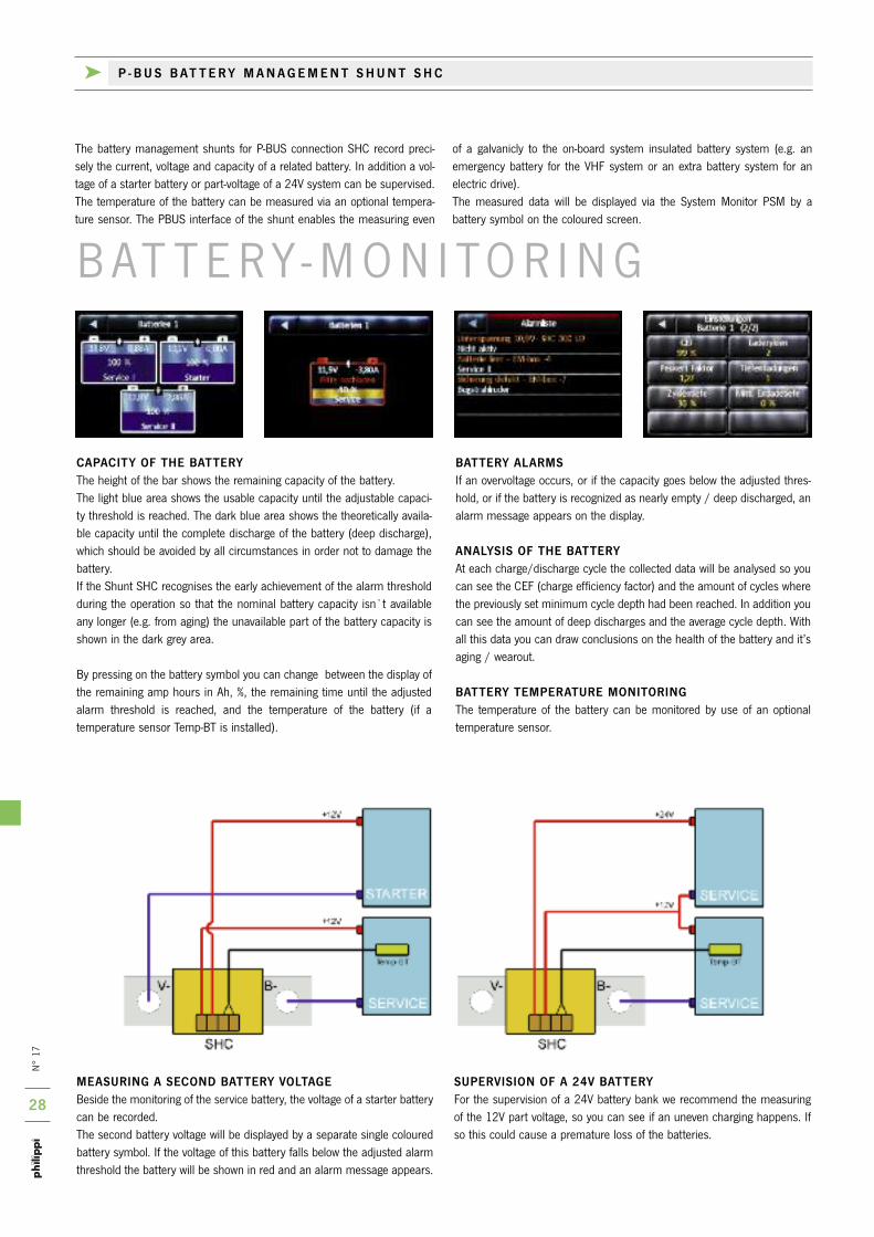
You need the Xcom-CAn interface if you want todisplay the data of the Xtender - inverter / chargercombination. Also it`s possible to enter the setupmenu for the configuration from the PSM by usingthe Xcom-CAn interface. Power supply via the Xtender - network.
Dimensions L 113 x W 76 x H 25 mm
if you got a Mastervolt lithium battery or aMastervolt inverter / charger combination youneed the CMB bridge in order to display the dataon the PSM. Also it`s possible to enter the setupmenu for the configuration from the PSM by usingthe CMB interface.Power supply via the Masterbus® network.
Dimensions H 66 x W 78 x D 32 mm
> CMB order-no.: 0 7100 0030> Xcom CAN order-no.: 7 0006 9042> CBN order-no.: 0 7100 0020
k P - B U S B R I D G E
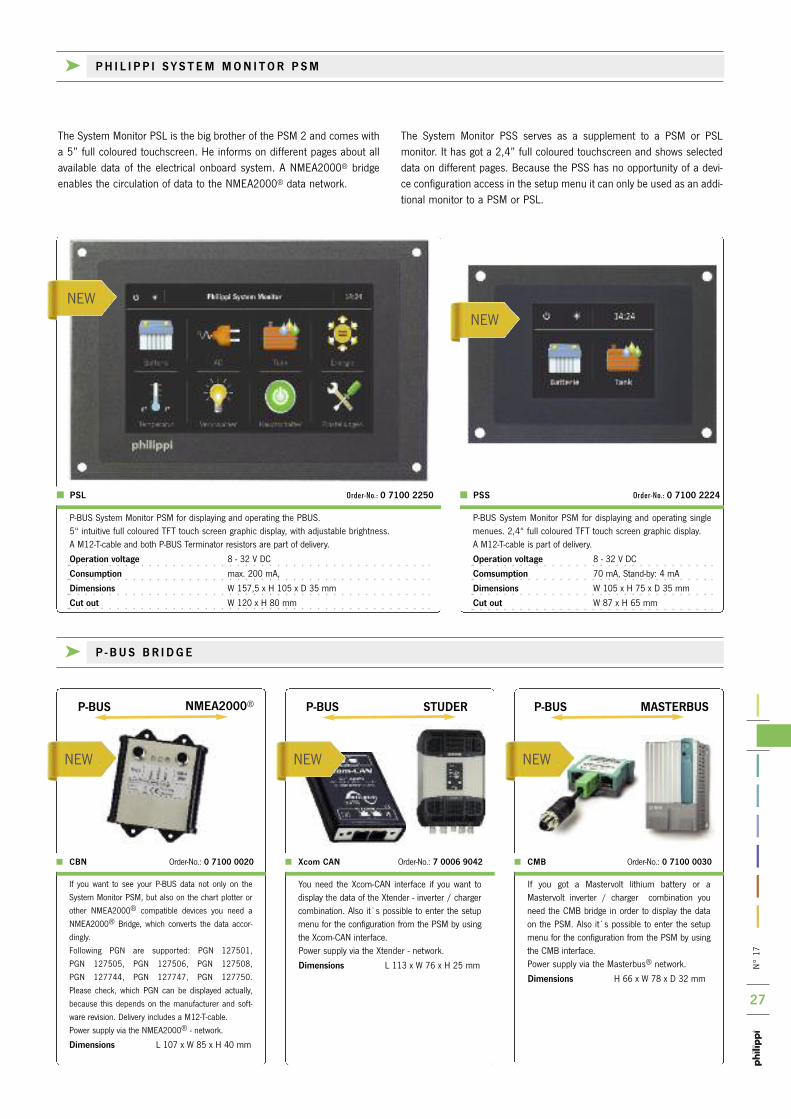
the System Monitor PSL is the big brother of the PSM 2 and comes witha 5” full coloured touchscreen. He informs on different pages about allavailable data of the electrical onboard system. A nMEA2000® bridgeenables the circulation of data to the nMEA2000® data network.
the System Monitor PSS serves as a supplement to a PSM or PSL monitor. it has got a 2,4” full coloured touchscreen and shows selecteddata on different pages. Because the PSS has no opportunity of a devi-ce configuration access in the setup menu it can only be used as an addi-tional monitor to a PSM or PSL.
P-BUS System Monitor PSM for displaying and operating the PBUS. 5“ intuitive full coloured tFt touch screen graphic display, with adjustable brightness.A M12-t-cable and both P-BUS terminator resistors are part of delivery.
Operation voltage 8 - 32 V DC
Consumption max. 200 mA,
Dimensions W 157,5 x H 105 x D 35 mm
Cut out W 120 x H 80 mm
P-BUS System Monitor PSM for displaying and operating singlemenues. 2,4“ full coloured tFt touch screen graphic display.A M12-t-cable is part of delivery.
Operation voltage 8 - 32 V DC
Comsumption 70 mA, Stand-by: 4 mA
Dimensions W 105 x H 75 x D 35 mm
Cut out W 87 x H 65 mm
PSL Order-No.: 0 7100 2250 PSS Order-No.: 0 7100 2224
if you want to see your P-BUS data not only on the
System Monitor PSM, but also on the chart plotter or
other nMEA2000® compatible devices you need a
nMEA2000® Bridge, which converts the data accor-
dingly.
Following PGn are supported: PGn 127501,
PGn 127505, PGn 127506, PGn 127508,
PGn 127744, PGn 127747, PGn 127750.
Please check, which PGn can be displayed actually,
because this depends on the manufacturer and soft-
ware revision. Delivery includes a M12-t-cable.
Power supply via the nMEA2000® - network.
Dimensions L 107 x W 85 x H 40 mm
k P H I L I P P I S Y S T E M M O N I T O R P S M
n°
17
28
B At t E r Y - M o n i to r i n G
MEASURING A SECOND BATTERY VOLTAGEBeside the monitoring of the service battery, the voltage of a starter batterycan be recorded. the second battery voltage will be displayed by a separate single colouredbattery symbol. if the voltage of this battery falls below the adjusted alarmthreshold the battery will be shown in red and an alarm message appears.
SUPERVISION OF A 24V BATTERYFor the supervision of a 24V battery bank we recommend the measuringof the 12V part voltage, so you can see if an uneven charging happens. ifso this could cause a premature loss of the batteries.
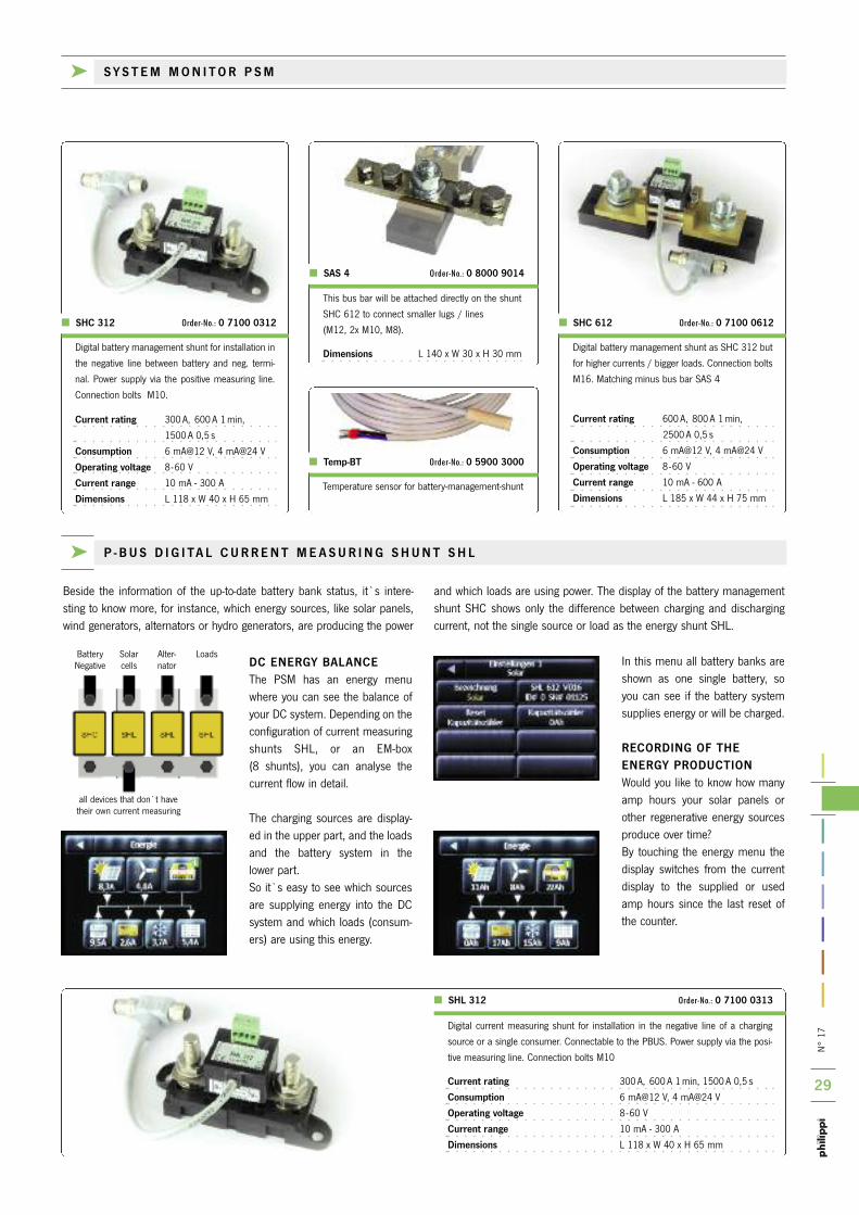
CAPACITY OF THE BATTERYthe height of the bar shows the remaining capacity of the battery.the light blue area shows the usable capacity until the adjustable capaci-ty threshold is reached. the dark blue area shows the theoretically availa-ble capacity until the complete discharge of the battery (deep discharge),which should be avoided by all circumstances in order not to damage thebattery.if the Shunt SHC recognises the early achievement of the alarm thresholdduring the operation so that the nominal battery capacity isn`t availableany longer (e.g. from aging) the unavailable part of the battery capacity isshown in the dark grey area.
By pressing on the battery symbol you can change between the display ofthe remaining amp hours in Ah, %, the remaining time until the adjustedalarm threshold is reached, and the temperature of the battery (if a temperature sensor temp-Bt is installed).
the battery management shunts for P-BUS connection SHC record preci-sely the current, voltage and capacity of a related battery. in addition a vol-tage of a starter battery or part-voltage of a 24V system can be supervised.the temperature of the battery can be measured via an optional tempera-ture sensor. the PBUS interface of the shunt enables the measuring even
of a galvanicly to the on-board system insulated battery system (e.g. an emergency battery for the VHF system or an extra battery system for an electric drive). the measured data will be displayed via the System Monitor PSM by a battery symbol on the coloured screen.
BATTERY ALARMSif an overvoltage occurs, or if the capacity goes below the adjusted thres-hold, or if the battery is recognized as nearly empty / deep discharged, analarm message appears on the display.
ANALYSIS OF THE BATTERYAt each charge/discharge cycle the collected data will be analysed so youcan see the CEF (charge efficiency factor) and the amount of cycles wherethe previously set minimum cycle depth had been reached. in addition youcan see the amount of deep discharges and the average cycle depth. Withall this data you can draw conclusions on the health of the battery and it’saging / wearout.
BATTERY TEMPERATURE MONITORINGthe temperature of the battery can be monitored by use of an optionaltemperature sensor.
k P - B U S B AT T E R Y M A N A G E M E N T S H U N T S H C
n°
17
29
Batterynegative
Solarcells
Alter-nator
all devices that don`t have their own current measuring
Loads
Digital current measuring shunt for installation in the negative line of a charging
source or a single consumer. Connectable to the PBUS. Power supply via the posi-
tive measuring line. Connection bolts M10
Current rating 300 A, 600 A 1 min, 1500 A 0,5 s
Consumption 6 mA@12 V, 4 mA@24 V
Operating voltage 8-60 V
Current range 10 mA - 300 A
Dimensions L 118 x W 40 x H 65 mm
SHL 312 Order-No.: 0 7100 0313
k P - B U S D I G I TA L C U R R E N T M E A S U R I N G S H U N T S H L
temperature sensor for battery-management-shunt
Temp-BT Order-No.: 0 5900 3000
DC ENERGY BALANCEthe PSM has an energy menuwhere you can see the balance ofyour DC system. Depending on theconfiguration of current measuringshunts SHL, or an EM-box (8 shunts), you can analyse thecurrent flow in detail.
the charging sources are display-ed in the upper part, and the loadsand the battery system in thelower part. So it`s easy to see which sourcesare supplying energy into the DCsystem and which loads (consum-ers) are using this energy.
in this menu all battery banks areshown as one single battery, soyou can see if the battery systemsupplies energy or will be charged.
RECORDING OF THE ENERGY PRODUCTIONWould you like to know how manyamp hours your solar panels orother regenerative energy sourcesproduce over time? By touching the energy menu thedisplay switches from the currentdisplay to the supplied or usedamp hours since the last reset ofthe counter.
Beside the information of the up-to-date battery bank status, it`s intere-sting to know more, for instance, which energy sources, like solar panels,wind generators, alternators or hydro generators, are producing the power
and which loads are using power. the display of the battery managementshunt SHC shows only the difference between charging and dischargingcurrent, not the single source or load as the energy shunt SHL.
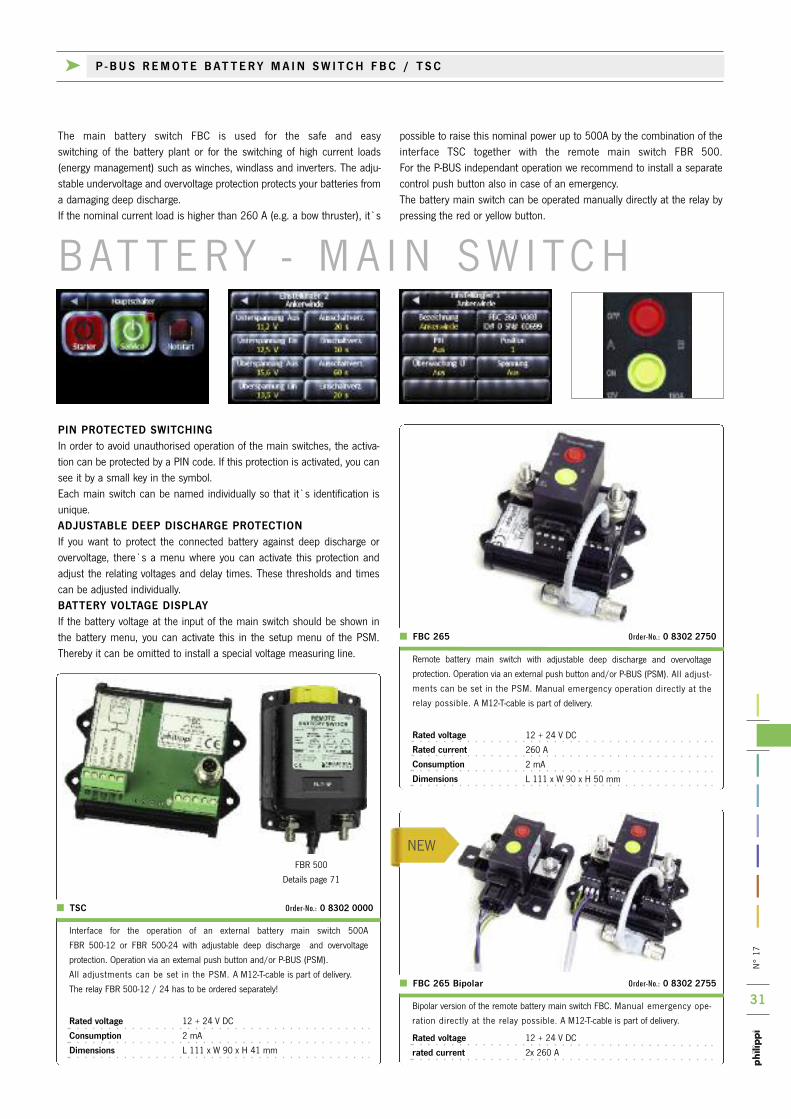
Digital battery management shunt for installation in
the negative line between battery and neg. termi-
nal. Power supply via the positive measuring line.
Connection bolts M10.
Current rating 300 A, 600 A 1 min,
1500 A 0,5 s
Consumption 6 mA@12 V, 4 mA@24 V
Operating voltage 8-60 V
Current range 10 mA - 300 A
Dimensions L 118 x W 40 x H 65 mm
Digital battery management shunt as SHC 312 but
for higher currents / bigger loads. Connection bolts
M16. Matching minus bus bar SAS 4
Current rating 600 A, 800 A 1 min,
2500 A 0,5 s
Consumption 6 mA@12 V, 4 mA@24 V
Operating voltage 8-60 V
Current range 10 mA - 600 A
Dimensions L 185 x W 44 x H 75 mm
SHC 312 Order-No.: 0 7100 0312 SHC 612 Order-No.: 0 7100 0612
this bus bar will be attached directly on the shunt
SHC 612 to connect smaller lugs / lines
(M12, 2x M10, M8).
Dimensions L 140 x W 30 x H 30 mm
SAS 4 Order-No.: 0 8000 9014
k S Y S T E M M O N I T O R P S M

n°
17
30P-BUS AC-interface for Din rail assembly for measuring of a single AC phase
230V / 50Hz. the connection by screw terminals. Connection to the P-BUS via a
M12 t-cable, which is part of delivery.
Current range 16 A (int. shunt)
100 A (via external converter WAC)
Dimensions L 76 x W 53 x H 46 mm
Current transformer max. 100 A sui-
table for AC-interface CAV
Dimensions
L 35 x W 35 x t 15 mm
CAV Order-No.: 0 7100 0230
WAC 100 Order-No.: 0 7100 4626
the AC interface CAV provides the AC performance data for the P-BUS: AC mains voltage V and AC mains current A Used kilowatt-hours kWh since last reset
in combination with an automa-tic switch over unit LAU (seepage 56) there`s the possibilityto display also the different ACsources, their voltages and theactive source.
k P - B U S TA N K I N T E R FA C E C M T 2 / A C I N T E R FA C E C A V
interface for the P-BUS for the integration / measurement of up to 4 different tank
sensors. Connection by plug-in screw terminals. Connection to the P-BUS via a M12-
terminal. A M12-t-cable is part of delivery.
Operation voltage DC 8-30 V
Consumption Stand by : 7,5 mA @ 13 V
Active : 10 mA @ 13 V
Dimensions L 107 x W 85 x H 40 mm
to get the level information of your tank sensors into the P-BUS networkyou need the interface CMt2. it receives the information of up to four sensors, supplies the sensors and provides this information to the
P-BUS. the adjustment of the parameters (like sensor type, tank volume,tank characteristic, alarm level etc.) will be done via the System MonitorPSM.
MANY TANK SENSORS CONNECTABLEYou can connect different tank sensors (also mixed) to the tank interfa-ce CMt 2: matching tank sensors please see page 40: tank sensor 10–180 ohm (Series tGW / tGt) tank sensor 240–33 ohm tank sensor 0–300 ohm (free adjustment) tank sensor 4–20 mA (Pressure sensor tDS) Ultrasonic-tank sensor 0,5–2,5 V (UtV) Ultrasonic-tank sensor: free adjustment of tank depth (UtV 40/80) tank sensor 0–5V (0–10V with hardware modification) Flow sensors DFS tank sensor 0–1 (Switch sensors trS 130 / rSW)
DISPLAY OF % OR LITRES (GALLONS FOR USA)By touching a tank symbol the display of the PSM switches between percent, no unit and litres / gallons.Flow sensor DFS: after having filled up the tank the volume can be adjus-ted by pressing the relating tank symbol for a while.
CONFIGURATION OF THE DISPLAYFor each connected tank sensor there is an individual menu in the setupof the PSM for the following adjustments: i.e. name, place, type of sen-sor, compensation, tank volume, alarm threshold, alarm duration.
COMPENSATION OF THE TANK GEOMETRYif your tank isn`t rectangular, there is a correction / compensationopportunity in order to get the most exact display for each display. if the tank is designed very unusual, the values for 0, 25, 50, 75 and100% can be set in the menu in order to get the optimum display of themeasured tank volume.
INTEGRATION OF A WATER MAKERBy using 2 Flow Sensors DFS the water level can be calculated by measuring both water consumption and water production (water maker).the sum will be displayed on the relating tank symbol on the PSM.
CMT 2 Order-No.: 0 7100 0401
k P - B U S A C I N T E R FA C E C A V
tA n k - M o n i to r i n G
nEW
nEW
n°
17
31
nEW
the main battery switch FBC is used for the safe and easy switching of the battery plant or for the switching of high current loads(energy management) such as winches, windlass and inverters. the adju-stable undervoltage and overvoltage protection protects your batteries froma damaging deep discharge.if the nominal current load is higher than 260 A (e.g. a bow thruster), it`s
possible to raise this nominal power up to 500A by the combination of theinterface tSC together with the remote main switch FBr 500. For the P-BUS independant operation we recommend to install a separatecontrol push button also in case of an emergency. the battery main switch can be operated manually directly at the relay bypressing the red or yellow button.
B At t E r Y - M A i n S W i tC H
PIN PROTECTED SWITCHINGin order to avoid unauthorised operation of the main switches, the activa-tion can be protected by a Pin code. if this protection is activated, you cansee it by a small key in the symbol.Each main switch can be named individually so that it`s identification isunique. ADJUSTABLE DEEP DISCHARGE PROTECTIONif you want to protect the connected battery against deep discharge orovervoltage, there`s a menu where you can activate this protection andadjust the relating voltages and delay times. these thresholds and timescan be adjusted individually. BATTERY VOLTAGE DISPLAYif the battery voltage at the input of the main switch should be shown inthe battery menu, you can activate this in the setup menu of the PSM.thereby it can be omitted to install a special voltage measuring line. remote battery main switch with adjustable deep discharge and overvoltage
protection. operation via an external push button and/or P-BUS (PSM). All adjust-
ments can be set in the PSM. Manual emergency operation directly at the
relay possible. A M12-t-cable is part of delivery.
Rated voltage 12 + 24 V DC
Rated current 260 A
Consumption 2 mA
Dimensions L 111 x W 90 x H 50 mm
Bipolar version of the remote battery main switch FBC. Manual emergency ope-
ration directly at the relay possible. A M12-t-cable is part of delivery.
Rated voltage 12 + 24 V DC
rated current 2x 260 A
FBC 265 Order-No.: 0 8302 2750
FBC 265 Bipolar Order-No.: 0 8302 2755
FBr 500
Details page 71
k P - B U S R E M O T E B AT T E R Y M A I N S W I T C H F B C / T S C
interface for the operation of an external battery main switch 500A
FBr 500-12 or FBr 500-24 with adjustable deep discharge and overvoltage
protection. operation via an external push button and/or P-BUS (PSM).
All adjustments can be set in the PSM. A M12-t-cable is part of delivery.
the relay FBr 500-12 / 24 has to be ordered separately!
Rated voltage 12 + 24 V DC
Consumption 2 mA
Dimensions L 111 x W 90 x H 41 mm
TSC Order-No.: 0 8302 0000

n°
17
32
nEW
k P - B U S S W I T C H I N G I N T E R FA C E C M R 4
Switching interface incl. 4 monostable relays (10 A nominal rating). integrated time
base for the system clock.
4 potential free relay outputs with fuseholder for a fuse / circuit breaker
4 operation inputs for direct switching at the interface
4 PWM-outputs for the dimming function (open-collector and 8V voltage signal )
Connection by screw terminals. M12-t-cable included in delivery..
Operation voltage DC 8-30 V
Consumption Stand by all relays off: 9 mA @ 13 V
Active all relays off: 13 mA @ 13 V
Active all relays on: 85 mA @ 13 V
Current rating / relay: 10 A
Dimensions L 115 x W 105 x H 50 mm
SWITCHING OF LOADS WITH DIMM FUNCTIONVia the System Monitor PSM loads can be switched on / off. there`s a biglibrary of graphic symbols to choose from. they can be named additional-ly.Also the E-T-A Powerplex-System can be operated by sending switchingmessages as well as receiving feedback information.
SWITCHING WITH FEEDBACKBy pressing the symbol button the load is switched on / off. A small green hook symbol shows that the load circuit is turned on.if the fuse protection at the output is blown, a small red flash symbol appe-ars.
DIMMING FUNCTION FOR LED-LIGHTSif the symbol button will be pressed longer, a new menu appears wherethe brightness of the lamp can be adjusted. Premise is a dimmable LEDlamp with a matching control input. For example LED lights from Prebit in the slave version can be connected and be dimmed.
E-T-A PowerplexCompact-Module
E-T-A PowerplexMarine-Module
CMR 4 Order-No.: 0 7100 0044
the switching interface CMr4 is designed to control 4 different load circu-its via the System Monitors PSM-V, PSM2 or PSL. Alternatively followingoperation functions can be realised:
ENERGY MANAGEMENTif the remaining battery capacity is low, you can switch off dedicated loads.the information for the switching operation will be delivered from a batterymanagement shunt SHC (you can choose between selected capacitylevels). You can operate monostable or bi-stable high current solenoids.
CONTROL OF AN AC GENERATORFor the operation of an AC generator with automatic start or start/stop buttons. the information for the switching operation will be delivered froma battery management shunt SHC (adjustment: Generator on/oFF). thisswitching information can be given by one or several shunts as well. to avoid the start of the generator (e.g. while the shore power is connec-ted) you have the possibility to connect a control signal. Also a workingtime can be fixed.
VISUALISATION OF ALARM MESSAGESif an alarm occurs on the PSM display you have the possibility to send thisalarm to an external buzzer or an alarm light at another place.
OPERATION OF PUMPS AT A TANK ALARMif a tank gives a level alarm (e.g. empty / full) a pump can be switched foran adjustable time.
the configuration of the switching interface CMr 4 will be done via thesystem monitor, no additional computer will be needed.
D i G i tA L S W i tC H i n G

n°
17
33
nEW
nEW
k P - B U S T E M P E R AT U R E I N T E R FA C E T P C 4
Following temperature values are interestingonboard of yachts and vehicles:
Air temperatures(inside / outside / battery area / engine room/ stowage space / refrigerator / ice box)
Water temperaturesEngine cooling water sweet and salty / exhaustcollector / sea water / water tank / water heater
Further temperaturesAlternator / gear box / exhaust / cylinder head/ turbocharger / engine block / engine oil
if you want to display important temperaturedegrees you can install a temperature interfacetPC 4. You can connect up to 4 temperaturesensors temp-Ht or temp-Bt. Up to four interfaces tPC 4 can be connected to the P-BUS.in the setup menu you can adjust a thresholdfor each temperature sensor individually, so theSystem Monitor PSM gives an alarm if the temperature falls below or rises above the adjusted limit.
the temperature Monitor tPM 5 shows up to5 temperature values. For the measuring thetemperature sensors temp-Bt or temp-Ht canbe used. the lettering (1-5) can be programmed ondemand to the customers specification.
temperature monitor in built-in housing for up to
5 temperatures. Delivery without temperature
sensors.
Operation voltage DC 8 -32 V
Consumption 8 mA
Dimensions (mm) L 105 x W 105 x t 40
Cut out 88 x 88 mm
interface for 4 temperature sensors
Connection via pluggable screw terminals.
A M12-t-cable is included in delivery.
Operation voltage DC 8 -32 V
Consumption 8 mA
Dimensions (mm) L 107 x W 85 x H 40
TPM 5 Order-No.: 0 8000 1010
TPC 4 Order-No.: 0 7100 0104
temperature sensor for temperature Monitor
tPM 5 and temperature interface tPC 4.
ntC- sensing element, encapsulated in a plastic
housing with PVC- cable 2,8 m.
Application: measuring of temperatures of water
and air between –30°C and +70°C.
temperature sensor for temperature monitor
tPM 5 and temperature interface tPC 4. ntC-sen-
sing element, encapsulated in a brass cable lug.
Hole Ø 4 mm, cable length 32 cm.
Application: temperature measuring between
+30°C and +250°C
Temp-BT Order-No.: 0 5900 3000 Temp-HT Order-No.: 0 5900 3300
k T E M P E R AT U R E M O N I T O R T P M 5
t E M P E r At U r E - M o n i to r i n G
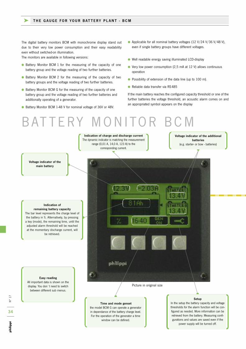
n°
17
34
Applicable for all nominal battery voltages (12 V/24 V/36 V/48 V), even if single battery groups have different voltages.
Well readable energy saving illuminated LCD-display
Very low power consumption (2,5 mA at 12 V) allows continuous operation
Possibility of extension of the data line (up to 100 m).
reliable data transfer via rS485
if the main battery reaches the configured capacity threshold or one of thefurther batteries the voltage threshold, an acoustic alarm comes on andan appropriated symbol appears on the display
the digital battery monitors BCM with monochrome display stand out due to their very low power consumption and their easy readability even without switched-on illumination. the monitors are available in following versions:
Battery Monitor BCM 1 for the measuring of the capacity of one battery group and the voltage reading of two further batteries.
Battery Monitor BCM 2 for the measuring of the capacity of two battery groups and the voltage reading of two further batteries.
Battery Monitor BCM G for the measuring of the capacity of one battery group and the voltage reading of two further batteries and additionally operating of a generator.
Battery Monitor BCM 1-48 V for nominal voltage of 36V or 48V.
Picture in original size
Time and mode gensetthe model BCM G can operate a generator in dependance of the battery charge level. For the operation of the generator a time
window can be defined.
Indication of remaining battery capacity
the bar level represents the charge level ofthe battery in %. Alternatively, by pressing
a key (mode), the remaining time, until theadjusted alarm threshold will be reachedat the momentary discharge current, will
be retrieved.
Easy readingAll important data is shown on thedisplay. You don`t need to switch
between different sub menus.
Setup in the setup the battery capacity and voltagethresholds for the alarm function will be con-figured as needed. More information can beretrieved from the battery. Measuring confi-gurations and values are saved even if the
power supply will be turned off.
Indication of charge and discharge currentthe dynamic indicator is matching the measurement
range (0,01 A, 14,0 A, 123 A) to the corresponding current.
Voltage indicator of the main battery
Voltage indicator of the additional batteries
(e.g. starter- or bow - batteries)
B At t E r Y M o n i to r B C M
k T H E G A U G E F O R YO U R B AT T E R Y P L A N T - B C M
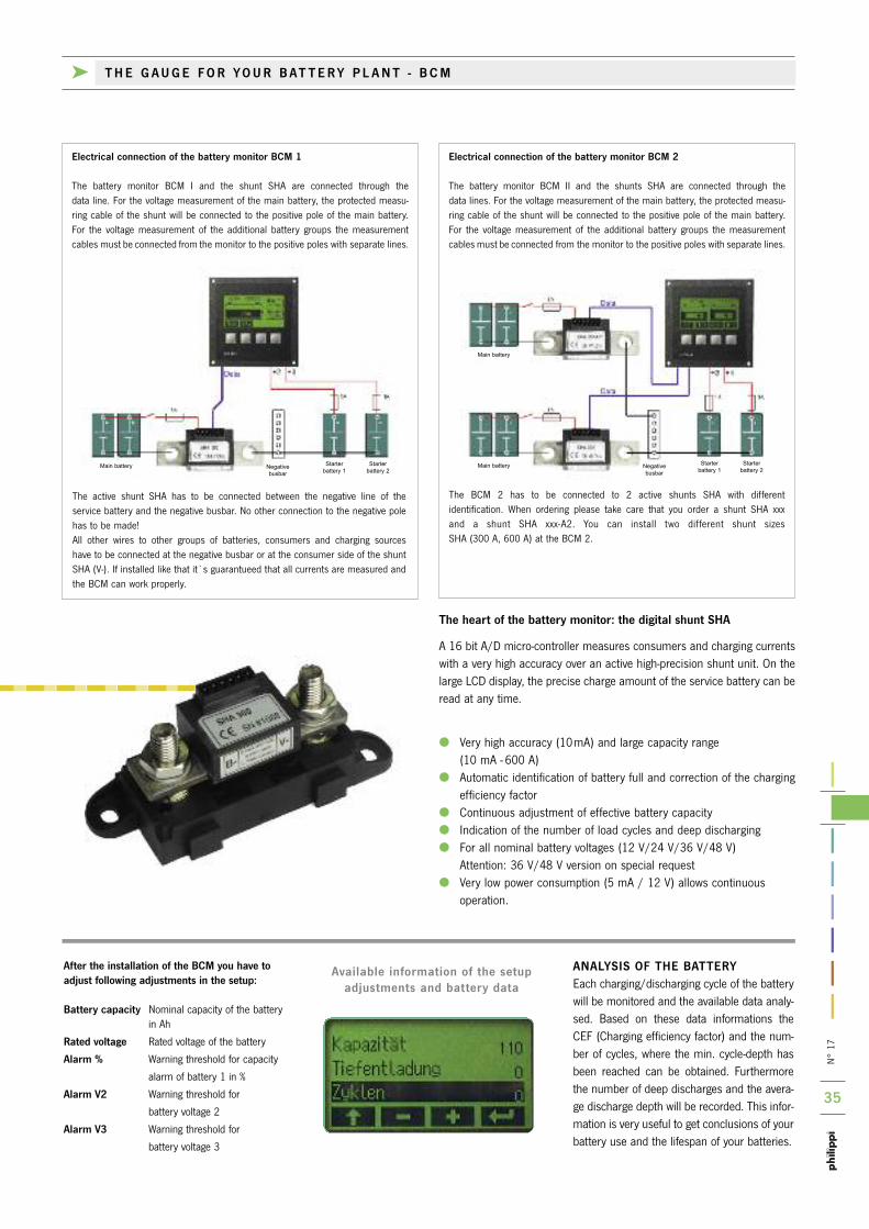
n°
17
35
ANALYSIS OF THE BATTERYEach charging/discharging cycle of the batterywill be monitored and the available data analy-sed. Based on these data informations theCEF (Charging efficiency factor) and the num-ber of cycles, where the min. cycle-depth hasbeen reached can be obtained. Furthermorethe number of deep discharges and the avera-ge discharge depth will be recorded. this infor-mation is very useful to get conclusions of yourbattery use and the lifespan of your batteries.
Available information of the setupadjustments and battery data
After the installation of the BCM you have toadjust following adjustments in the setup:
Battery capacity nominal capacity of the batteryin Ah
Rated voltage rated voltage of the battery
Alarm % Warning threshold for capacity
alarm of battery 1 in %
Alarm V2 Warning threshold for
battery voltage 2
Alarm V3 Warning threshold for
battery voltage 3
The heart of the battery monitor: the digital shunt SHA
A 16 bit A/D micro-controller measures consumers and charging currentswith a very high accuracy over an active high-precision shunt unit. on thelarge LCD display, the precise charge amount of the service battery can beread at any time.
Very high accuracy (10mA) and large capacity range (10 mA - 600 A)
Automatic identification of battery full and correction of the chargingefficiency factor
Continuous adjustment of effective battery capacity indication of the number of load cycles and deep discharging For all nominal battery voltages (12 V/24 V/36 V/48 V)
Attention: 36 V/48 V version on special request Very low power consumption (5 mA / 12 V) allows continuous
operation.
the BCM 2 has to be connected to 2 active shunts SHA with different identification. When ordering please take care that you order a shunt SHA xxx and a shunt SHA xxx-A2. You can install two different shunt sizes SHA (300 A, 600 A) at the BCM 2.
Electrical connection of the battery monitor BCM 1
the battery monitor BCM i and the shunt SHA are connected through the data line. For the voltage measurement of the main battery, the protected measu-ring cable of the shunt will be connected to the positive pole of the main battery.For the voltage measurement of the additional battery groups the measurementcables must be connected from the monitor to the positive poles with separate lines.
Electrical connection of the battery monitor BCM 2
the battery monitor BCM ii and the shunts SHA are connected through the data lines. For the voltage measurement of the main battery, the protected measu-ring cable of the shunt will be connected to the positive pole of the main battery.For the voltage measurement of the additional battery groups the measurementcables must be connected from the monitor to the positive poles with separate lines.
the active shunt SHA has to be connected between the negative line of the service battery and the negative busbar. no other connection to the negative polehas to be made!All other wires to other groups of batteries, consumers and charging sources have to be connected at the negative busbar or at the consumer side of the shunt SHA (V-). if installed like that it`s guarantueed that all currents are measured andthe BCM can work properly.
k T H E G A U G E F O R YO U R B AT T E R Y P L A N T - B C M
Main battery
Main battery
Main batteryNegative busbar
Negative busbar
Starterbattery 1
Starterbattery 2
Starterbattery 1
Starterbattery 2
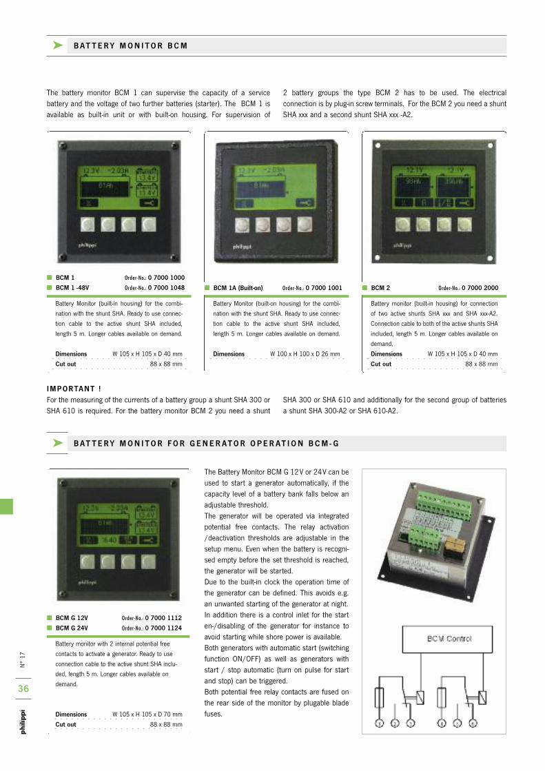
n°
17
36
Battery monitor with 2 internal potential free
contacts to activate a generator. ready to use
connection cable to the active shunt SHA inclu-
ded, length 5 m. Longer cables available on
demand.
Dimensions W 105 x H 105 x D 70 mm
Cut out 88 x 88 mm
BCM G 12V Order-No.: 0 7000 1112
BCM G 24V Order-No.: 0 7000 1124
the Battery Monitor BCM G 12V or 24V can beused to start a generator automatically, if thecapacity level of a battery bank falls below anadjustable threshold. the generator will be operated via integratedpotential free contacts. the relay activation/deactivation thresholds are adjustable in thesetup menu. Even when the battery is recogni-sed empty before the set threshold is reached,the generator will be started.Due to the built-in clock the operation time ofthe generator can be defined. this avoids e.g.an unwanted starting of the generator at night. in addition there is a control inlet for the starten-/disabling of the generator for instance toavoid starting while shore power is available. Both generators with automatic start (switchingfunction on/oFF) as well as generators withstart / stop automatic (turn on pulse for startand stop) can be triggered. Both potential free relay contacts are fused onthe rear side of the monitor by plugable bladefuses.
BCM 1 Order-No.: 0 7000 1000
BCM 1 -48V Order-No.: 0 7000 1048
Battery Monitor (built-in housing) for the combi-
nation with the shunt SHA. ready to use connec-
tion cable to the active shunt SHA included,
length 5 m. Longer cables available on demand.
Dimensions W 105 x H 105 x D 40 mm
Cut out 88 x 88 mm
BCM 1A (Built-on) Order-No.: 0 7000 1001 BCM 2 Order-No.: 0 7000 2000
Battery Monitor (built-on housing) for the combi-
nation with the shunt SHA. ready to use connec-
tion cable to the active shunt SHA included,
length 5 m. Longer cables available on demand.
Dimensions W 100 x H 100 x D 26 mm
Battery monitor (built-in housing) for connection
of two active shunts SHA xxx and SHA xxx-A2.
Connection cable to both of the active shunts SHA
included, length 5 m. Longer cables available on
demand.
Dimensions W 105 x H 105 x D 40 mm
Cut out 88 x 88 mm
IMPORTANT !For the measuring of the currents of a battery group a shunt SHA 300 orSHA 610 is required. For the battery monitor BCM 2 you need a shunt
SHA 300 or SHA 610 and additionally for the second group of batteries a shunt SHA 300-A2 or SHA 610-A2.
k B AT T E R Y M O N I T O R F O R G E N E R AT O R O P E R AT I O N B C M - G
the battery monitor BCM 1 can supervise the capacity of a service battery and the voltage of two further batteries (starter). the BCM 1 is available as built-in unit or with built-on housing. For supervision of
2 battery groups the type BCM 2 has to be used. the electrical connection is by plug-in screw terminals. For the BCM 2 you need a shuntSHA xxx and a second shunt SHA xxx -A2.
k B AT T E R Y M O N I T O R B C M

n°
17
37
Battery monitor with 2 internal potential free
contacts to activate a mono- or bistable relay.
ready to use connection cable to the active
shunt SHA included, length 5 m. Longer cables
available on demand.
Dimensions W 105 x H 105 x D 70 mm
Cut out 88 x 88 mm
recommended bistable high current relay 260 A:
FBR 265 Order-No.: 0 8302 2650
recommended bistable high current relay 500 A:
FBR 500-12V Order-No.: 7 0010 7700
FBR 500-24V Order-No.: 7 0010 7702
recommended monostable relay 70 A:
TR 70-12V Order-No.: 0 8000 7012
TR 70-24V Order-No.: 0 8000 7024
BCM BH 12V Order-No.: 0 7000 1212
BCM BH 24V Order-No.: 0 7000 1224
the battery monitor BCM BH 12 V or 24 V isdesigned to protect the battery bank from deepdischarge. An external high current relay will beoperated by two integrated potential free con-tacts in order to switch on/off the onboard elec-trical system. For the deactivation of the onboardsystem there are three different levels that canbe chosen from: the adjustable capacity thres-hold, the battery reserve threshold and theempty-alarm threshold. Even when a (weak) battery is recognised as empty before the setthreshold is reached, the system shuts down. 1-5 minutes before the system shutdown themonitor will warn by an optical and acousticalalarm in order to provide an opportunity to avoidthe upcoming shutdown - for example by activa-tion of a charger or starting the engine. By pressing a button at the monitor the mainswitch can be reactivated (emergency switch-on). A temperature sensor is available as optionfor temperature measuring of the battery.Monostable as well as bistable relais (only impul-se for on or off) are connectable.
Active shunt for up to 600A nominal current.
Suitable for loads / charging sources of max.
7200W (12V) or 14400W (24V). the shunt SHA
610 is for installation in the negative line between
battery and negative terminal.
Rated current 600 A,
800 A 1 min, 2500 A 0,5 s
Rated voltage 12 V , 24 V, 36 V, 48 V
Consumption 6 mA/12 V, 4 mA/24 V
Operation voltage 8-60 V
Current range 10 mA - 300 A
Dimensions L 185 x W 44 x H 68 mm
Cable connection M 16
Active shunt for up to 300A nominal current.
Suitable for loads / charging sources of max.
3600W (12V) or 7200W (24V). the shunt SHA
300 is for installation in the negative line between
battery and negative terminal.
Rated current 300 A,
600 A 1 min, 1500 A 0,5 s
Rated voltage 12 V , 24 V, 36 V, 48 V
Consumption 6 mA/12 V, 4 mA/24 V
Operation voltage 8-60 V
Current range 10 mA - 300 A
Dimensions L 118 x W 40 x H 65 mm
Cable connection M 10
SHA 610 Order-No.: 0 7000 0610
SHA 610-A2 Order-No.: 0 7000 0612
SHA 300 Order-No.: 0 7000 0300
SHA 300-A2 Order-No.: 0 7000 0302
k A C T I V E S H U N T S H A
this bus bar will be attached directly on the shunt
SHA 610 or SHC 612 to connect smaller lugs /
lines (M12, 2x M10, M8).
Dimensions L 140 x W 30 x H 30 mm
SAS 4 Order-No.: 0 8000 9014
Longer ready made cable (BCM2: cable set) for the
connection between shunt and monitor, if the 5m
cable isn`t long enough. Will be delivered instead of
the 5 m cable (set). other lengths are available.
SHA Kabel 10 m Order-No.: 0 7000 1099
SHA 2 Kabel 10 m Order-No.: 0 7000 1092
Fuse holder for blade fuse to protect voltage
measurement lines e.g. of the BCM.
Blade fuse (1A). included. Flat terminals 6,3mm.
ASH 1-1A Order-No.: 6 0030 3411
Battery temperature sensor for battery monitor
BCM - BH.
More information please see page 33.
Temp-BT Order-No.: 0 5900 3000
k B AT T E R Y M O N I T O R F O R R E M O T E M A I N S W I T C H B C M - B H
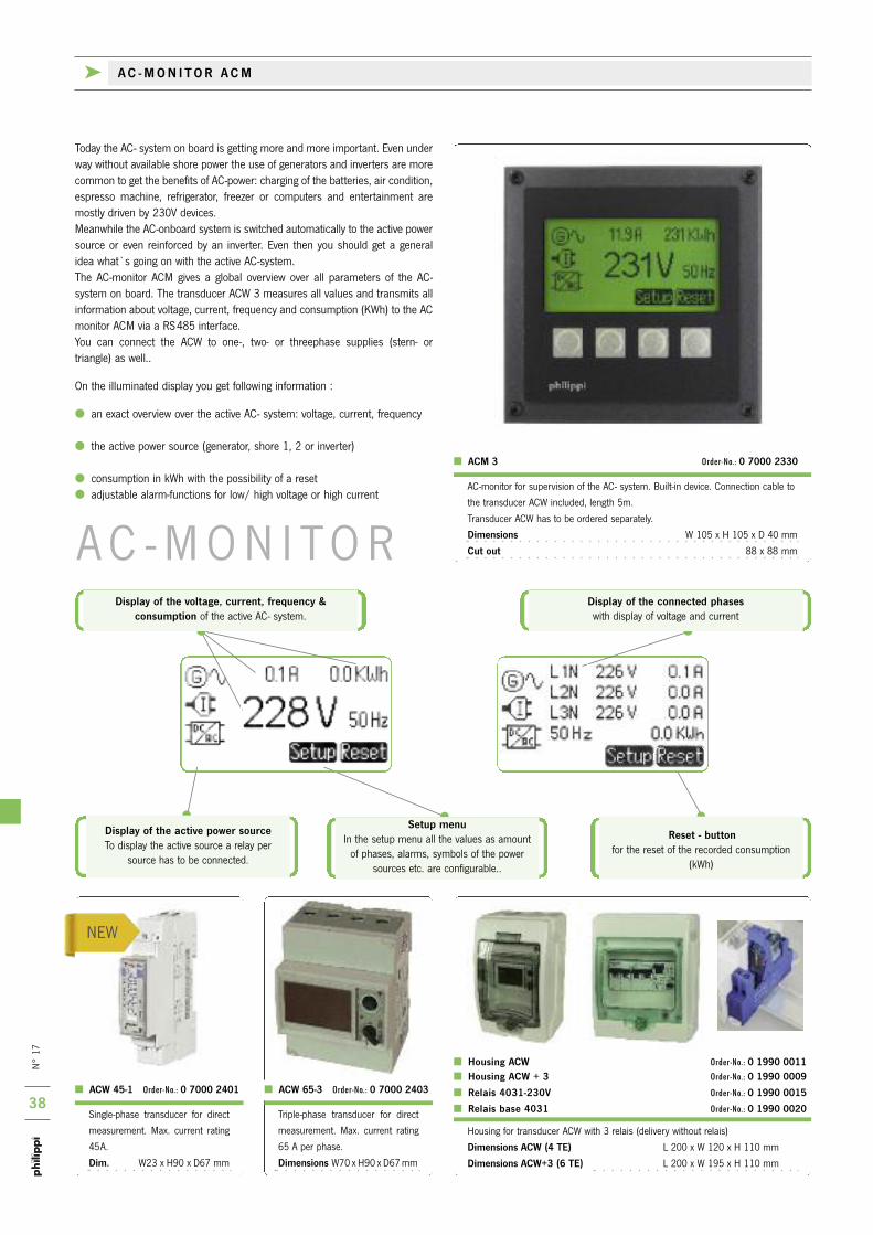
n°
17
38
nEW
Housing for transducer ACW with 3 relais (delivery without relais)
Dimensions ACW (4 TE) L 200 x W 120 x H 110 mm
Dimensions ACW+3 (6 TE) L 200 x W 195 x H 110 mm
Housing ACW Order-No.: 0 1990 0011 Housing ACW + 3 Order-No.: 0 1990 0009
Relais 4031-230V Order-No.: 0 1990 0015
Relais base 4031 Order-No.: 0 1990 0020
ACW 65-3 Order-No.: 0 7000 2403 ACW 45-1 Order-No.: 0 7000 2401
Single-phase transducer for direct
measurement. Max. current rating
45A.
Dim. W23 x H90 x D67 mm
triple-phase transducer for direct
measurement. Max. current rating
65 A per phase.
Dimensions W70 x H90 x D67 mm
today the AC- system on board is getting more and more important. Even underway without available shore power the use of generators and inverters are morecommon to get the benefits of AC-power: charging of the batteries, air condition,espresso machine, refrigerator, freezer or computers and entertainment aremostly driven by 230V devices. Meanwhile the AC-onboard system is switched automatically to the active powersource or even reinforced by an inverter. Even then you should get a generalidea what`s going on with the active AC-system.the AC-monitor ACM gives a global overview over all parameters of the AC-system on board. the transducer ACW 3 measures all values and transmits allinformation about voltage, current, frequency and consumption (kWh) to the ACmonitor ACM via a rS485 interface. You can connect the ACW to one-, two- or threephase supplies (stern- or triangle) as well..
on the illuminated display you get following information :
an exact overview over the active AC- system: voltage, current, frequency
the active power source (generator, shore 1, 2 or inverter)
consumption in kWh with the possibility of a reset adjustable alarm-functions for low/ high voltage or high current
ACM 3 Order-No.: 0 7000 2330
AC-monitor for supervision of the AC- system. Built-in device. Connection cable to
the transducer ACW included, length 5m.
transducer ACW has to be ordered separately.
Dimensions W 105 x H 105 x D 40 mm
Cut out 88 x 88 mm
Reset - buttonfor the reset of the recorded consumption
(kWh)
Display of the active power sourceto display the active source a relay per
source has to be connected.
Setup menuin the setup menu all the values as amount
of phases, alarms, symbols of the powersources etc. are configurable..
Display of the voltage, current, frequency & consumption of the active AC- system.
Display of the connected phaseswith display of voltage and current
A C - M o n i to r
k A C - M O N I T O R A C M
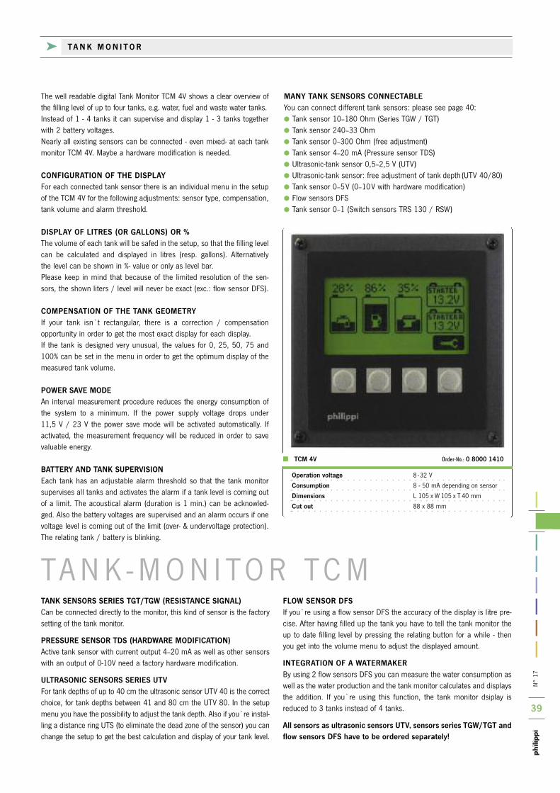
n°
17
39
tA n k - M o n i to r tC MTANK SENSORS SERIES TGT/TGW (RESISTANCE SIGNAL)Can be connected directly to the monitor, this kind of sensor is the factorysetting of the tank monitor.
PRESSURE SENSOR TDS (HARDWARE MODIFICATION)Active tank sensor with current output 4–20 mA as well as other sensorswith an output of 0-10V need a factory hardware modification.
ULTRASONIC SENSORS SERIES UTVFor tank depths of up to 40 cm the ultrasonic sensor UtV 40 is the correctchoice, for tank depths between 41 and 80 cm the UtV 80. in the setupmenu you have the possibility to adjust the tank depth. Also if you`re instal-ling a distance ring UtS (to eliminate the dead zone of the sensor) you canchange the setup to get the best calculation and display of your tank level.
FLOW SENSOR DFSif you`re using a flow sensor DFS the accuracy of the display is litre pre-cise. After having filled up the tank you have to tell the tank monitor theup to date filling level by pressing the relating button for a while - thenyou get into the volume menu to adjust the displayed amount.
INTEGRATION OF A WATERMAKERBy using 2 flow sensors DFS you can measure the water consumption aswell as the water production and the tank monitor calculates and displaysthe addition. if you`re using this function, the tank monitor dsiplay isreduced to 3 tanks instead of 4 tanks.
All sensors as ultrasonic sensors UTV, sensors series TGW/TGT andflow sensors DFS have to be ordered separately!
the well readable digital tank Monitor tCM 4V shows a clear overview of the filling level of up to four tanks, e.g. water, fuel and waste water tanks. instead of 1 - 4 tanks it can supervise and display 1 - 3 tanks togetherwith 2 battery voltages. nearly all existing sensors can be connected - even mixed- at each tankmonitor tCM 4V. Maybe a hardware modification is needed.
CONFIGURATION OF THE DISPLAYFor each connected tank sensor there is an individual menu in the setupof the tCM 4V for the following adjustments: sensor type, compensation, tank volume and alarm threshold.
DISPLAY OF LITRES (OR GALLONS) OR %the volume of each tank will be safed in the setup, so that the filling levelcan be calculated and displayed in litres (resp. gallons). Alternativelythe level can be shown in %- value or only as level bar. Please keep in mind that because of the limited resolution of the sen-sors, the shown liters / level will never be exact (exc.: flow sensor DFS).
COMPENSATION OF THE TANK GEOMETRYif your tank isn`t rectangular, there is a correction / compensationopportunity in order to get the most exact display for each display. if the tank is designed very unusual, the values for 0, 25, 50, 75 and100% can be set in the menu in order to get the optimum display of themeasured tank volume.
POWER SAVE MODEAn interval measurement procedure reduces the energy consumption ofthe system to a minimum. if the power supply voltage drops under 11,5 V / 23 V the power save mode will be activated automatically. ifactivated, the measurement frequency will be reduced in order to savevaluable energy.
BATTERY AND TANK SUPERVISIONEach tank has an adjustable alarm threshold so that the tank monitorsupervises all tanks and activates the alarm if a tank level is coming outof a limit. the acoustical alarm (duration is 1 min.) can be acknowled-ged. Also the battery voltages are supervised and an alarm occurs if onevoltage level is coming out of the limit (over- & undervoltage protection).the relating tank / battery is blinking.
MANY TANK SENSORS CONNECTABLEYou can connect different tank sensors: please see page 40: tank sensor 10–180 ohm (Series tGW / tGt) tank sensor 240–33 ohm tank sensor 0–300 ohm (free adjustment) tank sensor 4–20 mA (Pressure sensor tDS) Ultrasonic-tank sensor 0,5–2,5 V (UtV) Ultrasonic-tank sensor: free adjustment of tank depth (UtV 40/80) tank sensor 0–5V (0–10V with hardware modification) Flow sensors DFS tank sensor 0–1 (Switch sensors trS 130 / rSW)
Operation voltage 8 -32 V
Consumption 8 - 50 mA depending on sensor
Dimensions L 105 x W 105 x t 40 mm
Cut out 88 x 88 mm
TCM 4V Order-No.: 0 8000 1410
k TA N K M O N I T O R

n°
17
40
Panel with rocker switch (0-1) for a singleanalogue gauge l 52 mm.
Dimensions 110 x 72,5 x 40 mm
(90 mm incl. gauge)
TAN 101 Order-No.: 0 2800 0510
Analogue gauge l 52mm:
Fuel for tank sensors series tGt
Water for tank sensors series tGW
For the operation at 12 V DC. operating at
24 V DC requires a resistor "rturo" order
nr.: 2 0800 2000
Fuel 52 Order-No.: 2 0778 0541
Water 52 Order-No.: 2 0778 0601
Type Numbers of Required min. Order-No.:switch cont. tank depth
TGW 200 7 185 mm 6 6011 7091
TGW 250 10 235 mm 6 6011 7092
TGW 300 13 285 mm 6 6011 7093
TGW 350 16 335 mm 6 6011 7094
TGW 400 19 385 mm 6 6011 7095
TGW 450 23 435 mm 6 6011 7104
TGW 500 26 485 mm 6 6011 7096
TGW 600 32 585 mm 6 6011 7097
TGW 700 38 685 mm 6 6011 7098
TGW 800 44 785 mm 6 6011 7099
Flange and gasket are included in delivery!
Type Numbers of Required min. Order-No.:switch cont. tank depth
TGT 200 7 185 mm 6 6011 7080
TGT 250 10 235 mm 6 6011 7081
TGT 300 13 285 mm 6 6011 7082
TGT 350 16 335 mm 6 6011 7083
TGT 400 19 385 mm 6 6011 7084
TGT 450 23 435 mm 6 6011 7103
TGT 500 26 485 mm 6 6011 7085
TGT 600 32 585 mm 6 6011 7086
TGT 700 38 685 mm 6 6011 7087
TGT 800 44 785 mm 6 6011 7088
TGT 900 50 885 mm 6 6011 7089
Flange and gasket are included in delivery!
TRV Order-No.: 6 6011 9000
Tank sensor for water
Cover cap to close the tank during maintenance.
Flange with rubber gasket for fuel GWF,
Flange with rubber gasket for water GWW, food safeResolution 16 mmResistance Range 5-180 ohm Connection cable 2x 0,34 qmm,
length 10 cmInstallation vertical, ± 20°Temperature -10..+70 °CPressure max. 1 barProtection iP 65
the head of the sensor inclusive flange is 32 mm over
the tank surface.
Technical data TGT/TGW
GWF Order-No.: 6 6010 9000
GWW Order-No.: 6 6010 9002
Tank sensor for gasoline/fuel
Adapter flange for the installation of tank sensors tGt
/tGW to a given screw-hole circle matching the SAE-norm.
incl. are gasket and screws. Built-on height: 18 mm
GWA Order-No.: 6 6010 9010
to monitor the fluid levels of all tanks on board the high reso-lution sensor series tGt/tGW are the first choice. the tanksensors are constructed for vertical installation in water andfuel tanks. thanks to it`s flange mounting it`s easy to unscrew and takeout the tank sensor at any time for inspection purposes.
the sensors have reed contacts each 16 mm giving avery high resolution over the entire field instead of common simple systems with few contacts only.
the advantage over the normal sensors with a lever is thespace saving and reliable construction
the electronic is galvanicly insulated from the housing.this is important to avoid galvanic corrosion.
k TA N K M E A S U R I N G
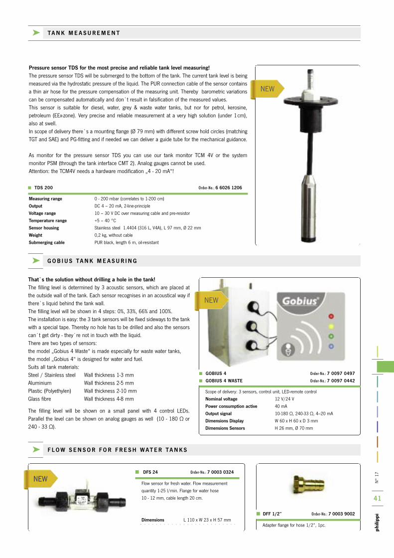
n°
17
41
nEW
nEWnEW
That`s the solution without drilling a hole in the tank!the filling level is determined by 3 acoustic sensors, which are placed atthe outside wall of the tank. Each sensor recognises in an acoustical way ifthere`s liquid behind the tank wall. the filling level will be shown in 4 steps: 0%, 33%, 66% and 100%. the installation is easy: the 3 tank sensors will be fixed sideways to the tankwith a special tape. thereby no hole has to be drilled and also the sensorscan`t get dirty - they`re not in touch with the liquid. there are two types of sensors:the model „Gobius 4 Waste“ is made especially for waste water tanks,the model „Gobius 4“ is designed for water and fuel.Suits all tank materials:Steel / Stainless steel Wall thickness 1-3 mm Aluminium Wall thickness 2-5 mm Plastic (Polyethylen) Wall thickness 2-10 mm Glass fibre Wall thickness 4-8 mm
the filling level will be shown on a small panel with 4 control LEDs. Parallel the level can be shown on analog gauges as well (10 - 180 Ω or 240 - 33 Ω).
Scope of delivery: 3 sensors, control unit, LED-remote control
Nominal voltage 12 V/24 V
Power consumption active 40 mA
Output signal 10-180 Ω, 240-33 Ω, 4–20 mA
Dimensions Display W 60 x H 60 x D 3 mm
Dimensions Sensors H 26 mm, Ø 70 mm
> GOBIUS 4 Order-No.: 7 0097 0497
> GOBIUS 4 WASTE Order-No.: 7 0097 0442
Flow sensor for fresh water. Flow measurement
quantity 1-25 l/min. Flange for water hose
10 - 12 mm, cable length 20 cm.
Dimensions L 110 x W 23 x H 57 mmAdapter flange for hose 1/2”, 1pc.
DFS 24 Order-No.: 7 0003 0324
DFF 1/2” Order-No.: 7 0003 9002
k F L O W S E N S O R F O R F R E S H W AT E R TA N K S
k G O B I U S TA N K M E A S U R I N G
Pressure sensor TDS for the most precise and reliable tank level measuring!the pressure sensor tDS will be submerged to the bottom of the tank. the current tank level is being measured via the hydrostatic pressure of the liquid. the PUr connection cable of the sensor containsa thin air hose for the pressure compensation of the measuring unit. thereby barometric variationscan be compensated automatically and don`t result in falsification of the measured values.this sensor is suitable for diesel, water, grey & waste water tanks, but nor for petrol, kerosine, petroleum (EEx-zone). Very precise and reliable measurement at a very high solution (under 1cm),also at swell. in scope of delivery there`s a mounting flange (Ø 79 mm) with different screw hold circles (matching tGt and SAE) and PG-fitting and if needed we can deliver a guide tube for the mechanical guidance.
As monitor for the pressure sensor tDS you can use our tank monitor tCM 4V or the system monitor PSM (through the tank interface CMt 2). Analog gauges cannot be used.Attention: the tCM4V needs a hardware modification „4 - 20 mA“!
Measuring range 0 - 200 mbar (correlates to 1-200 cm)
Output DC 4 – 20 mA, 2-line-principle
Voltage range 10 – 30 V DC over measuring cable and pre-resistor
Temperature range +5 – 40 °C
Sensor housing Stainless steel 1.4404 (316 L, V4A), L 97 mm, Ø 22 mm
Weight 0,2 kg, without cable
Submerging cable PUr black, length 6 m, oil-resistant
k TA N K M E A S U R E M E N T
> TDS 200 Order-No.: 6 6026 1206
nEW

n°
17
42
UTV
UFT
UTS 25
Distance ring for balancing
of the off zone
tank sensor for waste water tank
with indication of 3/4 level of the
tank. Full indication on 80 mm
before reaching the upper level.
Matching for tank depths from 200
to 400 mm.
Sensor length is 120 mm.
Delivery with flange & gasket.
Analogue gauge matching the ultra-
sonic sensor UtV.
operation at 12 V and 24 V DC.
Float lever for installation on the side of tanks for sensoring of the level. Depen-
ding on the installation position the switch opens or closes if the inside level rises
or falls. Housing -material Polyamid black suitable for oil or diesel.
Max. switching current: 0,5 A. installation from inside to outside.
Same function as float lever rSW. the DSW can be installed from outside without
installing a counternut from inside. the installation is easy, because the DSW has
a gasket ring which can be tightened from outside. Mounting hole: ø 22 - 24 mm.
Gasket 12 mm wide for wall thickness of max. 5 mm. only able to take small fil-
ling pressure. Max. switching current: 0,5 A. installation from outside!
RSW Order-No.: 0 8930 0008
DSW Order-No.: 0 8930 0019
Monitor panel for waste water tanks
with optical and acoustical alarm.
the acoustic alarm is acknowledge-
able by a push button.
Suitable for sensors trS 130 and
rSW / DSW.
Dimensions
L 105 x W 52,5 x D 50 mm
FAF -12V Order-No.: 0 2801 1020 FAF -24V Order-No.: 0 2802 1020
TRS 130 Order-No.: 6 6011 7102
Waste UTV No.: 2 0778 2041
k W A S T E W AT E R TA N K M E A S U R E M E N T
installation hole has to be min. 36 mm,
while using a focus tube it has to be
40 mm.
the contactless measurement of liquid level in tanks using ultrasonictechnology does not require mobile parts any more to be gotten dirty or damaged. Due to this fact they`re suitable especially for the measuringinside a waste water tank.
SYSTEM CAUSED LIMITATIONS:the „off“ zone 5 cm directly underneath the sensor cannot be measuredand the display shows possibly wrong values. the distance ring UtS servesas compensation for this zone. While a boat is under way, the heeling and swell makes a measurementimpossible. By using a focus tube UFt the measurement will be improved.it protects the sensor from dirt and stain and improves the measurement ifthere`s a froth on the liquid surface. Another positive effect is the acousticdecoupling at metal tanks, where a feedback could disturb the measure-ment.SUMMARY: we recommend ultrasonic sensors only for waste water tanks,
especially in connection with a focus tube UFt.
for fuel and water tanks they`re not really recommended because ofthe off zone (5 cm underneath the sensor) if the tank is full or nearlyfull.
While the boat / vehicle is under way you don`t get a reliable measurement.
UTV 20 200 mm 7 0219 3520
UTV 25 250 mm 7 0219 3525
UTV 30 300 mm 7 0219 3530
UTV 35 350 mm 7 0219 3535
UTV 40 400 mm 7 0219 3540
UTV 45 450 mm 7 0219 3545
UTV 50 500 mm 7 0219 3550
UTV 60 600 mm 7 0219 3560
UTV 70 700 mm 7 0219 3570
UTV 80 800 mm 7 0219 3580
Focus tube
UFT 40 400 mm 7 0219 9400
UFT 80 800 mm 7 0219 9800
incl. in delivery is a gasket
Built-on height 6 mm.
Distance ring
UTS 25 25 mm 7 0219 9025
incl. in delivery are a gasket and
5 screws
Input voltage 10 – 30 V
Consumption 50 mA
Output signal 0,5 V - 2,5 V
Switch-on time 5 s (1. measurement)
Averaging time 50 s
Temperature range -40°C to +85°C
Technichal data UTV
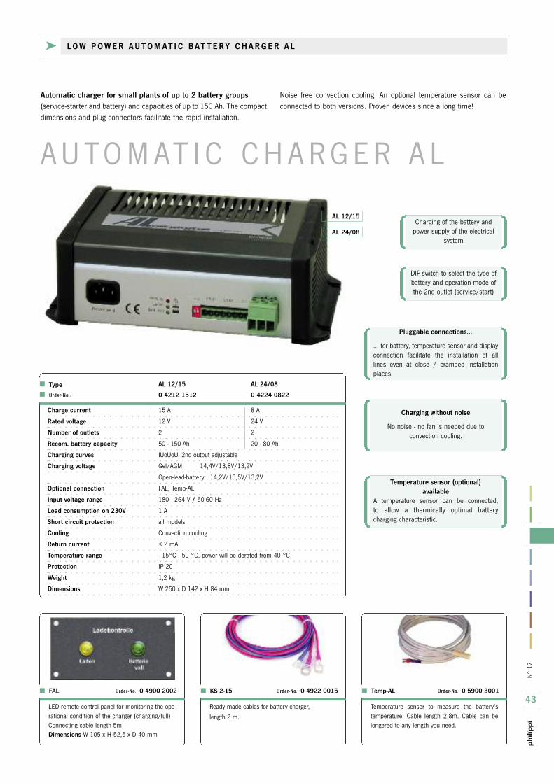
n°
17
43
A U to M At i C C H A r G E r A L
AL 24/08
AL 12/15Charging of the battery and
power supply of the electricalsystem
DiP-switch to select the type ofbattery and operation mode ofthe 2nd outlet (service/start)
Charging without noise
no noise - no fan is needed due to convection cooling.
Pluggable connections…
… for battery, temperature sensor and displayconnection facilitate the installation of alllines even at close / cramped installation places.
Temperature sensor (optional)available
A temperature sensor can be connected,to allow a thermically optimal battery charging characteristic.
ready made cables for battery charger,
length 2 m.
KS 2-15 Order-No.: 0 4922 0015
temperature sensor to measure the battery’stemperature. Cable length 2,8m. Cable can belongered to any length you need.
Temp-AL Order-No.: 0 5900 3001
LED remote control panel for monitoring the ope-rational condition of the charger (charging/full)Connecting cable length 5mDimensions W 105 x H 52,5 x D 40 mm
FAL Order-No.: 0 4900 2002
Charge current 15 A 8 A
Rated voltage 12 V 24 V
Number of outlets 2 2
Recom. battery capacity 50 - 150 Ah 20 - 80 Ah
Charging curves iUoUoU, 2nd output adjustable
Charging voltage Gel/AGM: 14,4V/13,8V/13,2V
open-lead-battery: 14,2V/13,5V/13,2V
Optional connection FAL, temp-AL
Input voltage range 180 - 264 V / 50-60 Hz
Load consumption on 230V 1 A
Short circuit protection all models
Cooling Convection cooling
Return current < 2 mA
Temperature range - 15°C - 50 °C, power will be derated from 40 °C
Protection iP 20
Weight 1,2 kg
Dimensions W 250 x D 142 x H 84 mm
Automatic charger for small plants of up to 2 battery groups(service-starter and battery) and capacities of up to 150 Ah. the compactdimensions and plug connectors facilitate the rapid installation.
noise free convection cooling. An optional temperature sensor can beconnected to both versions. Proven devices since a long time!
Type AL 12/15 AL 24/08
Order-No.: 0 4212 1512 0 4224 0822
k L O W P O W E R A U T O M AT I C B AT T E R Y C H A R G E R A L

n°
17
44
A L 1 2 / 1 5 F I
iCut out 227 x 150 mm
Double pole rCBo leakage pro-tector 16A/30mA to protect the
shore connection.
on/oFF switch and conditionoperation indicator
AC Mains and on-board control LEDsAC socket
When a battery will be discharged and not immediately re-chargedagain, the plates begin to sulphat. if the battery won`t be correctlycharged the sulphating becomes sulphate crystals what results in areduced battery capacity and also reduced life span of the battery.in case of a very strong sulphating great parts of the electrodes canbe permanently damaged. this means, the capacity goes down and also the voltage is lower. in case of a deep discharge the bat-tery got damaged irrevocable. the sulphating process will beegalised by a well controlled charging process with a 4 step charging characteristic.
Shore connection 230V/50Hz,and an extra AC connection at
the rear side terminals.
Connection for batteries andtemperature sensor on the rear
side terminals with screws
W h y i n v e s t i g a t e i n t o a h i g h -
q u a l i t y c h a r g e r t e c h n o l o g y ?
the charger AL 12/15 Fi was designed especially for small installations.it is based on the technique of automatic charger series AL combinedwith a shore power connection unit. this reduces the installation procedure, as only this device and a shore power connector is needed to
get a safe AC system with an AC socket and proper charger on board.the rCBo device and the socket are at the front side. Another AC connection possibility at the rear side provides a the safe connectionof further AC loads 230 V/50 Hz.
Charge current 15 A
Rated voltage 12 V
Charging characteristic iUoUoU-characteristic, Gel: 14,4V/13,8V/13,2V
open lead battery 14,2V/13,5V/13,2V
Number of outlets 2
Recom. battery capacity 50 - 150 Ah
Terminals for FAL, LCM, temp-AL
Input voltage range 180 - 264 V
Frequency 50-60 Hz
Load consumption on 230V 1 A
Weight 3 kg
Dimensions W 250 x H 174 x D 190 mm
Cooling Convection cooling without fan
Return current < 2 mA
Temperature range - 15°C - 50 °C, power derating from 40°C
Protection iP 20
Short circuit protection yes
AL 12/15 FI Order-No.: 0 4312 1512
Operation indicator
Front side: 3 coloured LEDs indicate the charge condition or
a failure condition.
Temperature compensated charging curve
to prevent harmful batterygassing, the maximum chargecurrent is reduced with everyrise in temperature. Up to twotemperature sensors can beconnected to monitor two
battery groups.
k A U T O M AT I C B AT T E R Y C H A R G E R I N C L . S H O R E P O W E R C O N N E C T I O N U N I T
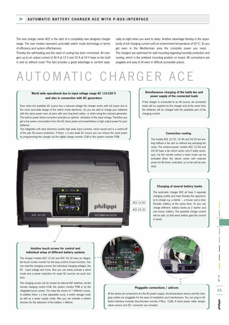
n°
17
45
ACE 24/30
ACE 12/60
Pluggable connections / add-ons
At the device all connections for the AC-power supply, the temperature sensor and the char-ging outlets are pluggable for the ease of installation and maintenance. You can plug in dif-ferent interface modules (touchscreen monitor, P-Bus, CLM). A shore power cable, tempe-rature sensor and DC- connector are included.
Convection cooling
the models ACE 12/25, 12/40 and 24/20 are wor-king without a fan and so without any annoying fannoise. the medium-power models ACE 12/60 and24/30 have a fan which works only if really neces-sary. Via the remote control a silent mode can beactivated (than the device works with reducedpower for 8h timer controlled, so no fan will be nee-ded).
Charging of several battery banks
the automatic charger ACE all have 3 separatecharging outlets and have thereby the opportuni-ty to charge e.g. a starter - , a house- and a bow-thruster- battery at the same time. or you cancharge different battery banks as 2 starter- andone house- battery. the available charge currentwill be split, so that every battery gets the currentit needs.
Simultaneous charging of the batte ries and power supply of the connected loads
if the charger is connected to an AC-source, all connectedloads will be supplied by the charger and at the same timethe batteries will be charged with the available part of thecharging current.
Intuitive touch screen for control and individual setup of different battery systems
the charger models ACE 12/60 and ACE 24/30 have an integra-ted touch screen monitor for the easy control of each function. Youcan read the charging current, the individual charging voltages, theAC - input voltage and more. Also you can easily activate a silentmode and a power reduction for weak AC sources via push but-tons.
the charging curves can be chosen by internal DiP switches, via theremote charging control CLM, the system monitor PSM or by theintegrated touch screen. You have the choice of 7 different curves.in addition there`s a free adjustable curve, a winter storage modeas well as a power supply mode. Also you can activate a refreshfunction for the extension of the battery`s lifetime.
A U to M At i C C H A r G E r A C E
the new charger series ACE is the start of a completely new designed chargerrange. the new models represent up-to-date switch mode technology in termsof efficiency and system effectiveness. thereby the self-heating and the need of cooling has been minimized. All char-gers up to an output current of 40 A at 12 V and 20 A at 24 V have no fan builtin and so without noise! this fact provides a great advantage in comfort espe-
cially at night when you want to sleep. Another advantage thereby is the oppor-tunity of full charging current until an environment temperature of 55°C. So youget even in the Mediterrean area the complete power you need. .the chargers are optimised for wall mounting regarding humidity protection andcooling, which is the prefered mounting position on board. All connections areplugable and easy to fit even in difficult accessible places.
World wide operational due to input voltage range AC 110-230 Vand also in connection with AC generators
Even when the available AC source has a reduced voltage the charger works with full power due tothe most up-to-date design of the switch mode electronic. So you are able to charge your batterieswith the same power even at piers with very long feed cables or while using the onboard generator.the built-in power factor-correction provides an optimal utilisation of the input energy. therefore yougot a low power consumption from the AC shore power and nevertheless a high output power for yourbatteries. the integrated soft start electronic avoids high peak input currents, which would end in a switch-offof the pier AC-source protection. if there`s a very weak AC source you can reduce the input powerby programming the charger via the digital charge monitor CLM or the system monitor PSM.
k A U T O M AT I C B AT T E R Y C H A R G E R A C E W I T H P - B U S - I N T E R FA C E
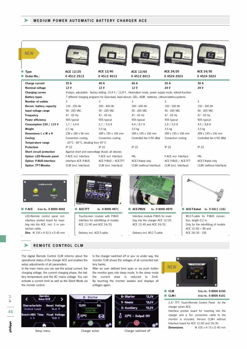
n°
17
46
nEW
nEW
k R E M O T E C O N T R O L C L M
Setup menu Charger active Charger switched off
the digital remote Control CLM informs about theoperational status of the charger ACE and enables thesetup adjustments of all parameters.in the main menu you can see the actual current, thecharging voltage, the current charging phase, the bat-tery temperature and the AC mains voltage. You canactivate a current limit as well as the Silent Mode viathe remote control.
is the charger switched off or you`re under way, themonitor CLM shows the voltages of all connected bat-tery banks. After an user defined time span or via push button the monitor goes into sleep mode. in the sleep modethe current draw is reduced to 3mA. By touching the monitor awakes and displays allvoltages again.
2,4“ tFt- touch-remote Control Panel for thecharger series ACE. interface printed board for inserting into the charger and a 5m connection cable to the monitor is included. Version CLM-i withoutinterface board for ACE 12/60 and 24/30.Dimensions W 105 x H 75 x D 40 mm
CLM Order-No.: 0 8000 4100
CLM-I Order-No.: 0 8000 4101
LED-remote control panel incl.interface printed board for inser-ting into the ACE. incl. 5 m con-nection cable.Dim. W 105 x H 52,5 x D 40 mm
F-ACE Order-No.: 0 8000 4002
M12-t-cable for P-BUS connec-tion, length 0,2 m.only for the retrofitting of modelsACE 12/60 + 80 and ACE 24/30 - 100
ACE-T-Kabel No.: 5 0411 1161
touchscreen module with P-BUSinterface for retrofitting of modelsACE 12/40 and ACE 24/20.
Delivery incl. ACE-t-cable.
ACE-TFT No.: 0 8000 4971
interface module P-BUS for inser-ting into the charger ACE 12/25,ACE 12/40 and ACE 24/20.
Delivery incl. M12 t-cable
ACE-PBUS No.: 0 8000 4970
k M E D I U M P O W E R A U T O M AT I C B AT T E R Y C H A R G E R A C E
Type ACE 12/25 ACE 12/40 ACE 12/60 ACE 24/20 ACE 24/30 Order-No.: 0 4512 2513 0 4512 4013 0 4512 6013 0 4524 2023 0 4524 3023
Charge current 25 A 40 A 60 A 20 A 30 A
Nominal voltage 12 V 12 V 12 V 24 V 24 V
Charging curves 4-steps, adjustable - factory setting: 14,4 V / 13,8 V , hibernation mode, power supply mode, refresh-function
Battery types 7 different charging programs for open-lead, lead-calcium, GEL-, AGM - batteries, Lithium-battery-systems
Number of outlets 3 3 3 3 3
Recom. battery capacity 120 - 250 Ah 200 - 400 Ah 300 - 600 Ah 100 - 200 Ah 150 - 300 Ah
Input voltage range 90 - 265 VAC 90 - 265 VAC 90 - 265 VAC 90 - 265 VAC 90 - 265 VAC
Frequency 47 - 65 Hz 47 - 65 Hz 47 - 65 Hz 47 - 65 Hz 47 - 65 Hz
Power efficiency 90% typical 90% typical 90% typical 90% typical 90% typical
Consumption 230 / 115 V 1,7 / 3,4 A 2,7 / 5,6 A 4,4 / 8,7 A 2,9 / 5,9 A 4,5 / 8,8 A
Weight 2,1 kg 3,5 kg 3,5 kg 3,5 kg 3,5 kg
Dimensions L x W x H 236 x 180 x 96 mm 289 x 195 x 106 mm 289 x 195 x 106 mm 289 x 195 x 106 mm 289 x 195 x 106 mm
Cooling Convection cooling Convection cooling Controlled fan (<50 dBa) Convection cooling Controlled fan (<50 dBa)
Temperature range - 20°C - 60°C, derating from 55°C
Protection iP 22 iP 22 iP 22 iP 22 iP 22
Short circuit protection Against short and overvoltage (fuse): all devices
Option: LED-Remote panel F-ACE incl. interface F-ACE incl. interface FAL F-ACE incl. interface FAL
Option: P-BUS-Interface interface ACE P-BUS ACE P-BUS / ACE-tFt ACE-t-kabel only ACE P-BUS / ACE-tFt ACE-t-kabel only
Option: TFT-Monitor CLM (incl. interface) CLM (incl. interface) CLM-i (without interface) CLM (incl. interface) CLM-i (without interface)
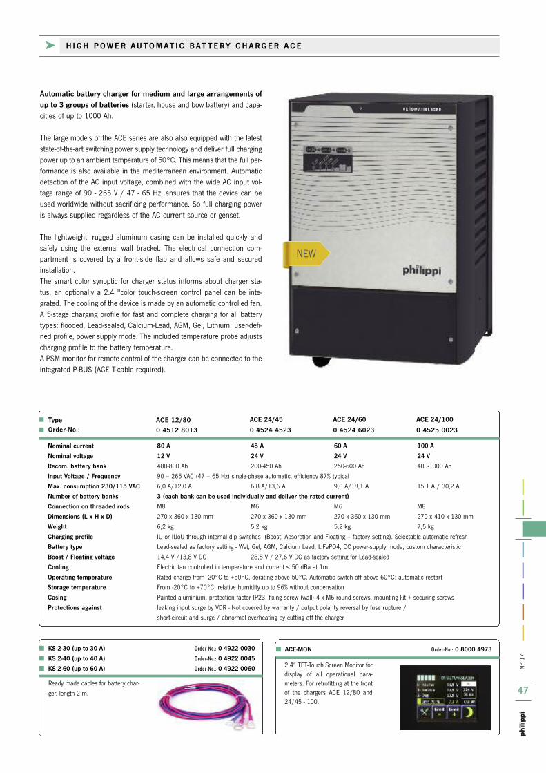
n°
17
47
nEW
KS 2-30 (up to 30 A) Order-No.: 0 4922 0030
KS 2-40 (up to 40 A) Order-No.: 0 4922 0045
KS 2-60 (up to 60 A) Order-No.: 0 4922 0060
ACE-MON Order-No.: 0 8000 4973
ready made cables for battery char-
ger, length 2 m.
2,4“ tFt-touch Screen Monitor fordisplay of all operational para-meters. For retrofitting at the frontof the chargers ACE 12/80 and24/45 - 100.
k H I G H P O W E R A U T O M AT I C B AT T E R Y C H A R G E R A C E
Automatic battery charger for medium and large arrangements ofup to 3 groups of batteries (starter, house and bow battery) and capa-cities of up to 1000 Ah.
the large models of the ACE series are also also equipped with the lateststate-of-the-art switching power supply technology and deliver full chargingpower up to an ambient temperature of 50°C. this means that the full per-formance is also available in the mediterranean environment. Automaticdetection of the AC input voltage, combined with the wide AC input vol-tage range of 90 - 265 V / 47 - 65 Hz, ensures that the device can beused worldwide without sacrificing performance. So full charging poweris always supplied regardless of the AC current source or genset.
the lightweight, rugged aluminum casing can be installed quickly andsafely using the external wall bracket. the electrical connection com-partment is covered by a front-side flap and allows safe and securedinstallation.the smart color synoptic for charger status informs about charger sta-tus, an optionally a 2.4 "color touch-screen control panel can be inte-grated. the cooling of the device is made by an automatic controlled fan.A 5-stage charging profile for fast and complete charging for all batterytypes: flooded, Lead-sealed, Calcium-Lead, AGM, Gel, Lithium, user-defi-ned profile, power supply mode. the included temperature probe adjustscharging profile to the battery temperature.A PSM monitor for remote control of the charger can be connected to theintegrated P-BUS (ACE t-cable required).
Nominal current 80 A 45 A 60 A 100 A
Nominal voltage 12 V 24 V 24 V 24 V
Recom. battery bank 400-800 Ah 200-450 Ah 250-600 Ah 400-1000 Ah
Input Voltage / Frequency 90 – 265 VAC (47 – 65 Hz) single-phase automatic, efficiency 87% typical
Max. consumption 230/115 VAC 6,0 A/12,0 A 6,8 A/13,6 A 9,0 A/18,1 A 15,1 A / 30,2 A
Number of battery banks 3 (each bank can be used individually and deliver the rated current)
Connection on threaded rods M8 M6 M6 M8
Dimensions (L x H x D) 270 x 360 x 130 mm 270 x 360 x 130 mm 270 x 360 x 130 mm 270 x 410 x 130 mm
Weight 6,2 kg 5,2 kg 5,2 kg 7,5 kg
Charging profile iU or iUoU through internal dip switches (Boost, Absorption and Floating – factory setting). Selectable automatic refresh
Battery type Lead-sealed as factory setting - Wet, Gel, AGM, Calcium Lead, LiFePo4, DC power-supply mode, custom characteristic
Boost / Floating voltage 14,4 V /13,8 V DC 28,8 V / 27,6 V DC as factory setting for Lead-sealed
Cooling Electric fan controlled in temperature and current < 50 dBa at 1m
Operating temperature rated charge from -20°C to +50°C, derating above 50°C. Automatic switch off above 60°C; automatic restart
Storage temperature From -20°C to +70°C, relative humidity up to 96% without condensation
Casing Painted aluminium, protection factor iP23, fixing screw (wall) 4 x M6 round screws, mounting kit + securing screws
Protections against leaking input surge by VDr - not covered by warranty / output polarity reversal by fuse rupture /
short-circuit and surge / abnormal overheating by cutting off the charger
Type ACE 12/80 ACE 24/45 ACE 24/60 ACE 24/100 Order-No.: 0 4512 8013 0 4524 4523 0 4524 6023 0 4525 0023
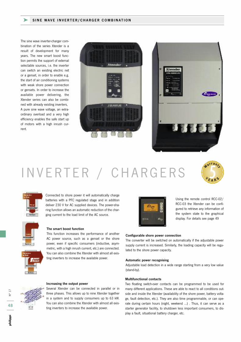
n°
17
48
5
k S I N E W A V E I N V E R T E R / C H A R G E R C O M B I N AT I O N
Y E A R S
Warrant y
i n V E r t E r / C H A r G E r SConnected to shore power it will automatically chargebatteries with a PFC regulated stage and in additiondeliver 230 V for AC supplied devices. the power-sha-ring function allows an automatic reduction of the char-ging current to the load limit of the AC source.
The smart boost functionthis function increases the performance of another AC power source, such as a genset or the shorepower, even if specific consumers (inductive, asym-metric, with a high inrush current, etc.) are connected.You can also combine the Xtender with almost all exis-ting inverters to increase the available power.
Increasing the output powerSeveral Xtender can be connected in parallel or inthree phases. this allows up to nine Xtender togetherin a system and to supply consumers up to 63 kW.You can also combine the Xtender with almost all exis-ting inverters to increase the available power.
Automatic power recognisingAdjustable load detection in a wide range starting from a very low value(stand-by).
Configurable shore power connectionthe converter will be switched on automatically if the adjustable powersupply current is increased. Similarly, the loading capacity will be regu-lated to the shore power capacity.
Using the remote control rCC-02/rCC-03 the Xtender can be confi-gured to retrieve any information ofthe system state to the graphicaldisplay. For details see page 49
Multifunctional contactstwo floating switch-over contacts can be programmed to be used formany different applications. these are able to react to all conditions out-side and inside the Xtender (availability of the shore power, battery volta-ge, fault detection, etc.). they are also time programmable, or can ope-rate during certain hours (night, weekend ...) . thus, it can serve as astarter generator facility, to shutdown less important consumers, to dis-play a fault, situational battery charger, etc.
the sine wave inverter-charger com-bination of the series Xtender is aresult of development for manyyears. the new smart boost func-tion permits the support of externalselectable sources, i.e. the invertercan switch an existing electric netor a genset, in order to enable e.g.the start of air conditioning systemswith weak shore power connectionor gensets. in order to increase theavailable power delivering, theXtender series can also be combi-ned with already existing inverters, A pure sine wave voltage, an extra-ordinary overload and a very highefficiency enables the safe start upof motors with a high inrush cur-rent.

n°
17
49
RCC-02 Order-No.: 7 0006 9020
BTS 01 Order-No.: 7 0006 9003
CAB-RJ45-2 (2m) Order-No.: 7 0006 9014
CAB-RJ45-5 (5m) Order-No.: 7 0006 9015
CAB-RJ45-20 (20m) Order-No.: 7 0006 9016
remote monitor for control and display of theinverter/charger series XtM / XtH. Build-in version. incl. connecting cable 2 m.
Dimensions W130 x H 120 x D 40 mm
remote monitor for control and display of theinverter/charger series XtM / XtH. Build-on version. incl. connecting cable 2 m.
Dimensions L 170 x W 170 x H 45 mm
Add-on module for remote control on/oFF of theinverter/charger series XtM / XtH. For Din rail assembly. incl. connecting cable 3 m.
Dimensions W 45 x H 73 x D 45 mm
RCC-03 Order-No.: 7 0006 9030 RCM 10 Order-No.: 7 0006 9005
information on the condition of the combinedinverter series XtH can be retrieved using thegraphical display of the remote control rCC-02/-03. in addition it can recognize, display andrecord, on time, all fault conditions to potentialproblems.
Using the graphical display of the remote con-trol rCC-02/-03 you can configure many set-tings at the remote rCC-02/-03 for the combi-
ned inverter, such as the charging curves of thebattery charger and the various operatingmodes. Also the programming of two auxiliarycontacts, for example a starting generator faci-lity, shutdown of less important consumers, dis-play a fault, display current conditions of bat-tery charging is possible.
For example there are three generator startingmodes and one generator stopping mode for a
freely adjustable voltage-time combination avai-lable. Furthermore performance factors of thecombined inverters can be added. Using the remote control rCC-02/-03 the inte-grated SD Card can be pre-configured in thecombined inverter externally or update soft-ware, so that the device is always up-to-date.
Battery temperature sensor to adjust the char-ging voltage to the battery temperature.Cable length 3 mDimensions W 58 x H 52 x D 23 mm
XCOM 232i Order-No.: 7 0006 9040
Communikation module CAn/rS-232 with datalogger function for X-tender XtS / XtM / XtH/ Vt.Dimensions L 113 x W 76 x H 25 mm
Communication cable to connect the invertercombination with remote control rCC 02/03, orto build three-phase systems or parallel connec-tion of several devices.
Nominal input voltage 12 V 12 V 12 V 24 V 24 V 24 V
Input voltage range 9,5 V - 17 V 9,5 V - 17 V 9,5 V - 17 V 19 V - 34 V 19 V - 34 V 19 V - 34 V
Output voltage, -frequency Sine 230 V AC (± 2 %), 50 Hz ± 0,05 % (adjustble from 45 to 65 Hz)
Distortion THD < 2 %
Cos a max. 0,1 - 1
Rated power 1500 VA 2000 VA 2500 VA 2000 VA 3000 VA 4500 VA
Max. power 30 min 1500 VA 2000 VA 3000 VA 2400 VA 3500 VA 5000 VA
Max. power 5 sec 3400 VA 4800 VA 7500 VA 6000 VA 9000 VA 12000 VA
max. efficiency 93 % 93 % 93 % 94 % 94 % 94 %
Consumption off / stand by /on 1,2/1,4/8 W 1,2/1,4/10 W 1,7/2,2/14 W 1,4/1,6/9 W 0,8/0,9/9 W 1,8/2,5/20 W
Rated current. 135 A 180 A 225 A 89 A 134 A 178 A
Charging current adjustable 0 - 70 A 0 - 100 A 0 - 160 A 0 - 55 A 0 - 90 A 0 - 140 A
Max. current transfer system 50 A 50 A 50 A 50 A 50 A 50 A
Weight 15 kg 18,5 kg 34 kg 16,2 kg 21,2 kg 40 kg
Dimensions (L x W x H) in mm 322 x 133 x 466 322 x 133 x 466 300 x 230 x 500 322 x 133 x 466 322 x 133 x 466 300 x 230 x 500
Inverter/charger XTM 1500-12 XTM 2000-12 XTH 3000-12 XTM 2400-24 XTM 3500-24 XTH 5000-24 Order-No.: 7 0003 1512 7 0003 2012 7 0003 3012 7 0003 2424 7 0003 3524 7 0003 5024
k S I N E W A V E I N V E R T E R / C H A R G E R C O M B I N AT I O N

n°
17
50
k S I N E - W A V E I N V E R T E R / C H A R G E R C O M B I N AT I O N X P C
the solar charge controller Variotrack complieswith the highest industrial standards, is very flexible and programmable and gives you thereby the most optimal power from your solarplant. if the Variotrack is connected to the batteries and the solar panels, it charges thebatteries automatically and with the highestefficiency of the available solar energy due to aclever algorithm, which searches the highestpossible working level (MPPt). the MaximumPower Point tracking, MPPt, supervises
continuously the solar plant for the optimal voltage in order to receive the maximum available power. this working level variies permanently in dependency of the environmen-tal conditions (solar radiation, temperature) towhich the Variotrack has to adapt itself (tracking). By using the most advanced technology the efficiency is at the highest level:tracking & energy efficiency: > 99% 4-step charging characteristic for a longer
battery lifespan. 8 pre- defined standard battery charging curves.
Completely configurable system: Comprehensive display, setup possibility
and data protocols by using the remote control monitors rCC-02/-03
Compatible to all solar systems Maximum utilisation together with a
Xtender system and a synchronised battery management
Nominal input voltage 12 V 24 V
Input voltage range 9,5 V - 16 V 19 V - 34 V
Output voltage, -frequency Sine 230 V AC (0 / -10 %), 50 Hz ± 0,05 %
Distortion THD < 2 %
Cos phi max. 0,1 - 1
Rated power 1100 VA 1600 VA
Max. power 30 min 1400 VA 2200 VA
Max. power 5 sec 3300 VA 4800 VA
max. efficiency 94 % 95 %
Consumption off/stand by/on 0,5/0,6/4 W 0,8/0,9/7 W
Rated current. 98 A 100 A
Charging current adjustable 0 - 45 A 0 - 37 A
Max. current transfer system 16 A 16 A
Weight 11,7 kg 12,6 kg
Dimensions (L x W x H) in mm 215 x 145 x 410 215 x 145 x 410
Inverter/charger XPC 1400-12 XPC 2200-24 Order-No.: 7 0006 1112 7 0006 1824
CT 35 Order-No.: 7 0006 9001
the sine wave inverter-charger combination of theseries XPC are very interested in pricing. other thenthe series XtM and XtH they don`t have a smart-boost-function, so that the power of the inverter can-
not be added to the shore- or generator power. Almostall functions are adjustable directly on the device,optional there`s a remote control rCC 01 available.
Battery temperature sensor toadjust the charging voltage to thebattery temperature.Cable length 3 mDim. W 58 x H 52 x D 23 mm
RCC 01 Order-No.: 7 0006 9000
remote control for monitoring anddisplay of inverter/charger seriesXPC. incl. connecting cable 20 m.Dimensions:L 112 x B 138 x H 25 mm
k S O L A R C H A R G E C O N T R O L L E R V A R I O T R A C K
max. charging current 65 A 80 A
Battery nominal voltage 12 / 24 / 48 V 12 / 24 / 48 V
max. solar panel voltage 80 V 80 V
max. power of the PV 1000 / 2000 / 4000 W 1250 / 2500 / 5000 W
Weight 5,2 kg 5,5 kg
Dimensions W x D x H 120 x 220 x 310 mm 120 x 220 x 350 mm
Return current < 1 W in night mode
Protection iP 54 iP 54
Special features Protection against wrong connection and pole - changing
VarioTrack VT 65 VT 80
Order-No.: 7 0006 8065 7 0006 8080
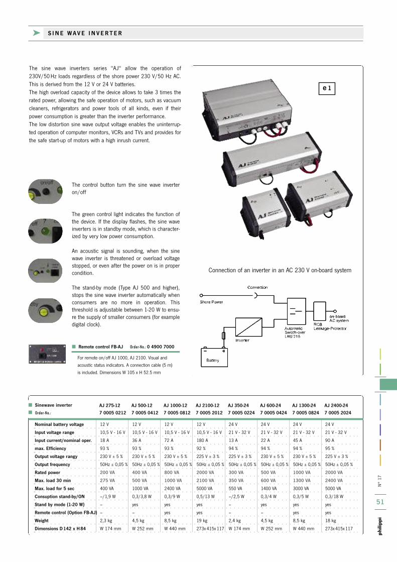
n°
17
51
e 1
k S I N E W A V E I N V E R T E R
Nominal battery voltage 12 V 12 V 12 V 12 V 24 V 24 V 24 V 24 V
Input voltage range 10,5 V - 16 V 10,5 V - 16 V 10,5 V - 16 V 10,5 V - 16 V 21 V - 32 V 21 V - 32 V 21 V - 32 V 21 V - 32 V
Input current/nominal oper. 18 A 36 A 72 A 180 A 13 A 22 A 45 A 90 A
max. Efficiency 93 % 93 % 93 % 92 % 94 % 94 % 94 % 95 %
Output voltage rangy 230 V ± 5 % 230 V ± 5 % 230 V ± 5 % 225 V ± 3 % 225 V ± 3 % 230 V ± 5 % 230 V ± 5 % 225 V ± 3 %
Output frequency 50Hz ± 0,05 % 50Hz ± 0,05 % 50Hz ± 0,05 % 50Hz ± 0,05 % 50Hz ± 0,05 % 50Hz ± 0,05 % 50Hz ± 0,05 % 50Hz ± 0,05 %
Rated power 200 VA 400 VA 800 VA 2000 VA 300 VA 500 VA 1000 VA 2000 VA
Max. load 30 min 275 VA 500 VA 1000 VA 2100 VA 350 VA 600 VA 1300 VA 2400 VA
Max. load for 5 sec 400 VA 1000 VA 2400 VA 5000 VA 550 VA 1400 VA 3000 VA 5000 VA
Consuption stand-by/ON –/1,9 W 0,3/3,8 W 0,3/9 W 0,5/13 W –/2,5 W 0,3/4 W 0,3/5 W 0,3/18 W
Stand by mode (1-20 W) – yes yes yes – yes yes yes
Remote control (Option FB-AJ) – – yes yes – – yes yes
Weight 2,3 kg 4,5 kg 8,5 kg 19 kg 2,4 kg 4,5 kg 8,5 kg 18 kg
Dimensions D 142 x H 84 W 174 mm W 252 mm W 440 mm 273x 415x 117 W 174 mm W 252 mm W 440 mm 273x 415x 117
Sinewave inverter AJ 275-12 AJ 500-12 AJ 1000-12 AJ 2100-12 AJ 350-24 AJ 600-24 AJ 1300-24 AJ 2400-24 Order-No.: 7 0005 0212 7 0005 0412 7 0005 0812 7 0005 2012 7 0005 0224 7 0005 0424 7 0005 0824 7 0005 2024
Connection of an inverter in an AC 230 V on-board system
the control button turn the sine wave inverteron/off
the green control light indicates the function ofthe device. if the display flashes, the sine waveinverters is in standby mode, which is character-ized by very low power consumption.
An acoustic signal is sounding, when the sinewave inverter is threatened or overload voltagestopped, or even after the power on is in propercondition.
the stand-by mode (type AJ 500 and higher),stops the sine wave inverter automatically whenconsumers are no more in operation. thisthreshold is adjustable between 1-20 W to ensu-re the supply of smaller consumers (for exampledigital clock).
Remote control FB-AJ Order-No.: 0 4900 7000
For remote on/off AJ 1000, AJ 2100. Visual and
acoustic status indicators. A connection cable (5 m)
is included. Dimensions W 105 x H 52.5 mm
the sine wave inverters series "AJ" allow the operation of230V/50 Hz loads regardless of the shore power 230 V/50 Hz AC.this is derived from the 12 V or 24 V batteries.the high overload capacity of the device allows to take 3 times therated power, allowing the safe operation of motors, such as vacuumcleaners, refrigerators and power tools of all kinds, even if theirpower consumption is greater than the inverter performance.the low distortion sine wave output voltage enables the uninterrup-ted operation of computer monitors, VCrs and tVs and provides forthe safe start-up of motors with a high inrush current.

N° 17
52
DC/DC Converter 24V/12VPV 3s 7 0020 0003 24 V / 12 V 3 A 6 A 10 mA / 7 mA 87 x 50 x 71 mm 256 g
PV 6s 7 0020 0006 24 V / 12 V 6 A 10 A 10 mA / 7 mA 87 x 50 x 88 mm 318 g
PV 12s 7 0020 0012 24 V / 12 V 12 A 18 A 10 mA / 7 mA 87 x 50 x 126 mm 455 g
PV 18s 7 0020 0018 24 V / 12 V 18 A 21 A 10 mA / 7 mA 87 x 50 x 166 mm 610 g
PV 24s 7 0020 0024 24 V / 12 V 24 A 30 A 10 mA / 9 mA 87 x 50 x 166 mm 610 g
DD 24-12 600 7 0020 0050 24 V / 12 V 50 A 60 A 22 mA / 22 mA 80 x 100 x 300 mm 1100 g
DC/DC Converter 24V/12V with galvanicly isolated outputPV 3i 7 0021 0003 24 V / 12 V 3 A 6 A 11 mA / 3 mA 87 x 50 x 88 mm 318 g
PV 12i 7 0021 0012 24 V / 12 V 12 A 18 A 11 mA / 3 mA 87 x 50 x 166 mm 610 g
PV 24 i 7 0021 0024 24 V / 12 V 24 A 30 A 11 mA / 3 mA 87 x 50 x 216 mm 750 g
DC/DC Converter 12V/12V or 24V/24V with galvanicly isolated outputDDi 12-12 36 7 0022 1103 8-18 V / 13.6 V 3 A 4 A 17 mA / 0 mA 87 x 50 x 88 mm 318 g
DDi 12-12 72 7 0022 1107 8-18 V / 13.6 V 6 A 10 A 17 mA / 0 mA 87 x 50 x 166 mm 610 g
DDi 24-24 240 7 0022 2224 16-36 V / 27.2 V 10 A 12 A 17 mA / 0 mA 87 x 62 x 217 mm 880 g
DC/DC Converter 24V/12VDD 12-24 72 7 0022 1207 12 V / 26.5 V 3 A (24 V) 4 A (24 V) 110 mA / 40 mA 87 x 50 x 88 mm 318 g
DD 12-24 240 7 0022 1228 12 V / 27.6 V 10 A (24 V) 12 A (24 V) 10 mA / 10 mA 87 x 50 x 217 mm 820 g
DD 12-24 600 7 0022 1260 12 V / 27,.6 V 25 A (24 V) 30 A (24 V) 10 mA / 10 mA 125 x 74 x 283 mm 1860 g
DC/DC Converter 48V/12VDD 48-12 108 7 0022 4111 48 V / 13.6 V 9 A (12 V) 11 A (12 V) 15 mA 87 x 50 x 127 mm 420 g
> Type Order-No.: Input-/ Rated power Max. load Quicent current/ Dimensions Weight
Output voltage (ED=33%) Back current L x W x H
Technical data for the models PV (24/12V)
Input voltage range(PV) 17 - 32 V
Output voltage range (PV) 13.6 - 13.9 V
Ripple < 50 mV
Efficiency typ. 93 %
Operation temperature from 30 °C: current decreasing
Converter in a compact housing. Switch mode technology in SMD
technology. Stable aluminium housing with nylon end caps.
Electronic protection against overheating and over-voltage.
Protection against inverted polarity by internal fuse. Connection via
plug contacts 6.3 mm. Supply with assembly clips.
Protection IP 53.
Many navigation devices, radios and receivers cannot be used with a 24 V power supply, because they are designed for 12 V operation only.A DC/DC converter converts an input of 24 V to an output of 12 V forpowering all the equipment which is designed for 12 V supply.
An additional battery for supplying 12 V units together with a charger 12 V isn´ t necessary. Also the harmful drawing of 12 V out of a batteryblock 24 V is unnecessary.
> Efficiency typ. 93 %Small heat development by up to date circuit technology
> Life time warrantyOptimal circuit design makes high durabilitypossible.
> Easy installationSnap on by assembly clips
> Completed galvanic isolated output (Type PV i)Type PVi with galvanic separated output for isolatedpower supply on board of ships and cars .
k D C / D C C O N V E R T E R
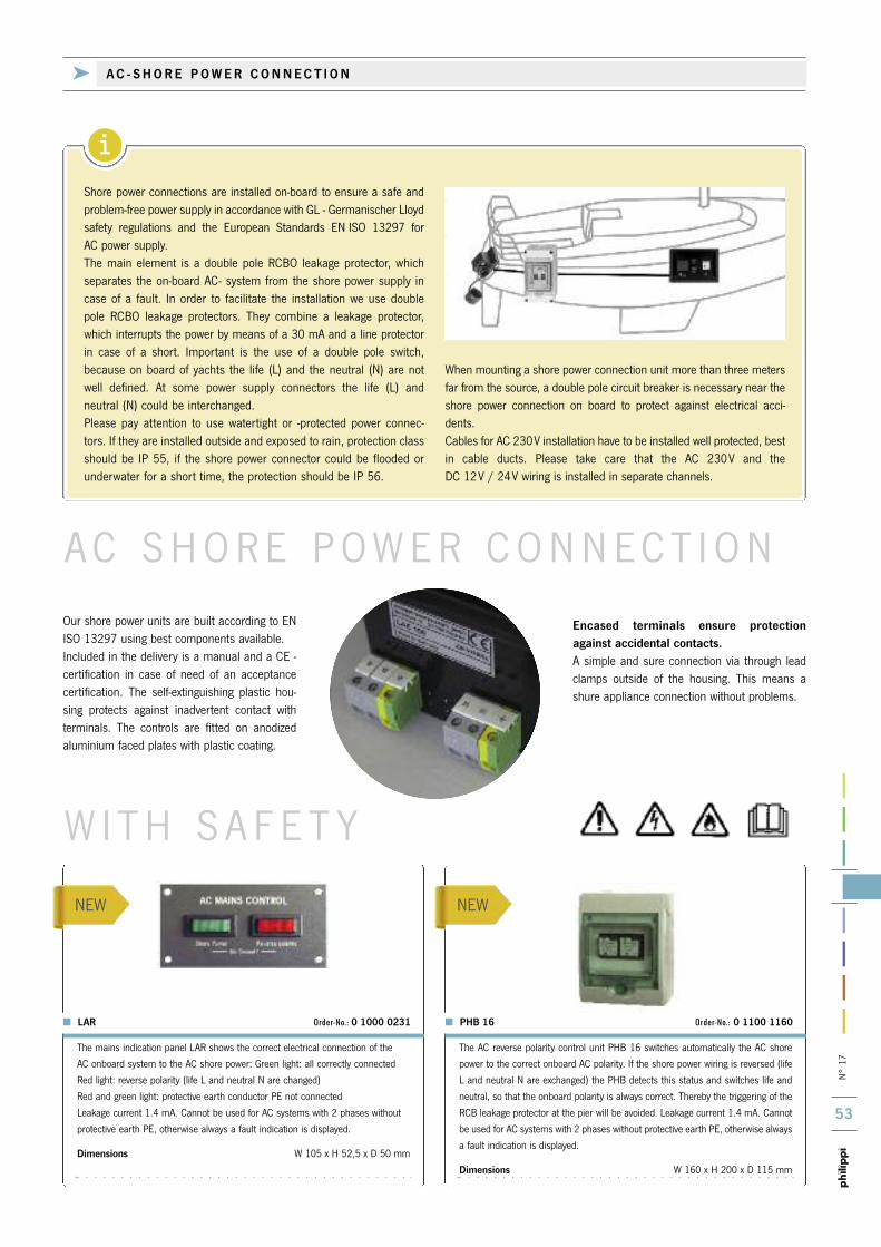
N° 17
53
i
NEW NEW
W I TH S A F E T Y
AC SHORE POWER CONNECT I ON
k A C - S H O R E P O W E R C O N N E C T I O N
Our shore power units are built according to ENISO 13297 using best components available.Included in the delivery is a manual and a CE -certification in case of need of an acceptancecertification. The self-extinguishing plastic hou-sing protects against inadvertent contact withterminals. The controls are fitted on anodizedaluminium faced plates with plastic coating.
Shore power connections are installed on-board to ensure a safe and problem-free power supply in accordance with GL - Germanischer Lloydsafety regulations and the European Standards EN ISO 13297 for AC power supply.The main element is a double pole RCBO leakage protector, whichseparates the on-board AC- system from the shore power supply incase of a fault. In order to facilitate the installation we use doublepole RCBO leakage protectors. They combine a leakage protector,which interrupts the power by means of a 30 mA and a line protectorin case of a short. Important is the use of a double pole switch,because on board of yachts the life (L) and the neutral (N) are notwell defined. At some power supply connectors the life (L) and neutral (N) could be interchanged.Please pay attention to use watertight or -protected power connec-tors. If they are installed outside and exposed to rain, protection classshould be IP 55, if the shore power connector could be flooded orunderwater for a short time, the protection should be IP 56.
When mounting a shore power connection unit more than three metersfar from the source, a double pole circuit breaker is necessary near theshore power connection on board to protect against electrical acci-dents.Cables for AC 230V installation have to be installed well protected, bestin cable ducts. Please take care that the AC 230V and the DC 12V / 24V wiring is installed in separate channels.
Encased terminals ensure protectionagainst accidental contacts.A simple and sure connection via through leadclamps outside of the housing. This means ashure appliance connection without problems.
The mains indication panel LAR shows the correct electrical connection of the
AC onboard system to the AC shore power: Green light: all correctly connected
Red light: reverse polarity (life L and neutral N are changed)
Red and green light: protective earth conductor PE not connected
Leakage current 1.4 mA. Cannot be used for AC systems with 2 phases without
protective earth PE, otherwise always a fault indication is displayed.
Dimensions W 105 x H 52,5 x D 50 mm
LAR Order-No.: 0 1000 0231
The AC reverse polarity control unit PHB 16 switches automatically the AC shore
power to the correct onboard AC polarity. If the shore power wiring is reversed (life
L and neutral N are exchanged) the PHB detects this status and switches life and
neutral, so that the onboard polarity is always correct. Thereby the triggering of the
RCB leakage protector at the pier will be avoided. Leakage current 1.4 mA. Cannot
be used for AC systems with 2 phases without protective earth PE, otherwise always
a fault indication is displayed.
Dimensions W 160 x H 200 x D 115 mm
PHB 16 Order-No.: 0 1100 1160

N° 17
54
iC o n n e c t i o n o f g e n s e t s a n d i n v e r t e r s a c c o r d i n g t o E N / I S O 1 3 2 9 7
LAE 110 Order-No.: 0 1000 1100
Shore power connection unit for 230 V/50 Hz cycles supply and Schuko-Socket.AC control lights show correct shore power connection. 2 circuit breakers 10 A forcharger and heater. Connection at rear side of unit for 230V via through leadclamps.
RCBO Leakage protector RCBO 16A/0,03A 2-poleDimensions W 260 x H 185 x D 100 mmCut-out measurements W 235 x H 160 mm
LAE 101 Order-No.: 0 1000 1010
Shore power connection unit for 230 V/50 Hz cycles supply and Schuko-Socket.AC control lights show correct shore power connection. Connection at rear side ofunit for 230 V via through lead clamps.
RCBO leakage protector RCBO 16A/0,03A 2-poleDimensions W 185 x H 150 x D 100 mmCut-out measurements W 160 x H 125 mm
Shore power connection unit for 230 V/50 Hz cycles supply. AC control lightsshow correct shore power connection. Connection at rear side of unit for 230 Vvia through lead clamps.
RCBO leakage protector RCBO 16A/0,03A 2-poleDimensions W 150 x H 185 x D 100 mmCut-out measurements W 125 x H 160 mm
LAE 100 Order-No.: 0 1000 1003
k S H O R E P O W E R C O N N E C T I O N U N I T S
For additional AC power sources on board, as a generator and/or aninverter, all poles must be separated by a switching device. This willprevent a simultaneous connection of multiple sources in the on-board system. Additionally, the switch over unit must have a voltme-
ter. Control lights show the availability of power sources. During theuse of an inverter the operating of a charger must be excluded because the charger would use the power from the inverter and thebatteries would be discharged unintentionally without any use.
LAE 111 Order-No.: 0 1000 1110
Combined shore/genset or shore/inverter power unit for AC-power 230 V/50 Hz.with double pole switch over, current rating max. 25A, AC control lights show avai-lable sources, voltmeter 250 V. 4 double pole thermal circuit breakers 10 A.Connection at rear side of unit for 230V via through lead clamps.
RCBO Leakage Protector RCBO 25A/0,03A 2-poleDimensions W 260 x H 185 x D 100 mmCut-out measurements W 235 x H 160 mm
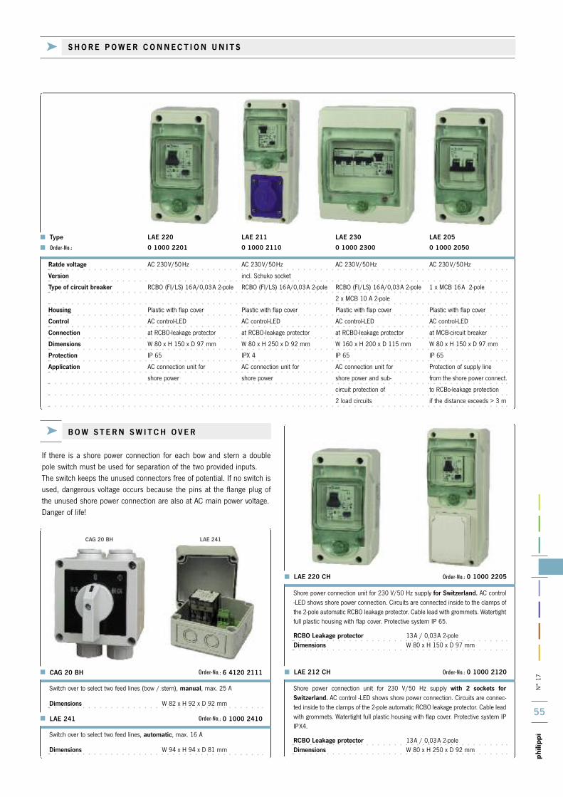
N° 17
55
CAG 20 BH LAE 241
LAE 220 CH Order-No.: 0 1000 2205
Shore power connection unit for 230 V/50 Hz supply for Switzerland. AC control-LED shows shore power connection. Circuits are connected inside to the clamps ofthe 2-pole automatic RCBO leakage protector. Cable lead with grommets. Watertightfull plastic housing with flap cover. Protective system IP 65.
RCBO Leakage protector 13A / 0,03A 2-poleDimensions W 80 x H 150 x D 97 mm
Ratde voltage AC 230V/50Hz AC 230V/50Hz AC 230V/50Hz AC 230V/50Hz
Version incl. Schuko socket
Type of circuit breaker RCBO (FI/LS) 16A/0,03A 2-pole RCBO (FI/LS) 16A/0,03A 2-pole RCBO (FI/LS) 16A/0,03A 2-pole 1 x MCB 16A 2-pole
2 x MCB 10 A 2-pole
Housing Plastic with flap cover Plastic with flap cover Plastic with flap cover Plastic with flap cover
Control AC control-LED AC control-LED AC control-LED AC control-LED
Connection at RCBO-leakage protector at RCBO-leakage protector at RCBO-leakage protector at MCB-circuit breaker
Dimensions W 80 x H 150 x D 97 mm W 80 x H 250 x D 92 mm W 160 x H 200 x D 115 mm W 80 x H 150 x D 97 mm
Protection IP 65 IPX 4 IP 65 IP 65
Application AC connection unit for AC connection unit for AC connection unit for Protection of supply line
shore power shore power shore power and sub- from the shore power connect.
circuit protection of to RCBo-leakage protection
2 load circuits if the distance exceeds > 3 m
LAE 212 CH Order-No.: 0 1000 2120
k S H O R E P O W E R C O N N E C T I O N U N I T S
Shore power connection unit for 230 V/50 Hz supply with 2 sockets forSwitzerland. AC control -LED shows shore power connection. Circuits are connec-ted inside to the clamps of the 2-pole automatic RCBO leakage protector. Cable leadwith grommets. Watertight full plastic housing with flap cover. Protective system IPIPX4.
RCBO Leakage protector 13A / 0,03A 2-poleDimensions W 80 x H 250 x D 92 mm
k B O W S T E R N S W I T C H O V E R
If there is a shore power connection for each bow and stern a doublepole switch must be used for separation of the two provided inputs. The switch keeps the unused connectors free of potential. If no switch isused, dangerous voltage occurs because the pins at the flange plug ofthe unused shore power connection are also at AC main power voltage. Danger of life!
Type LAE 220 LAE 211 LAE 230 LAE 205
Order-No.: 0 1000 2201 0 1000 2110 0 1000 2300 0 1000 2050
LAE 241 Order-No.: 0 1000 2410
CAG 20 BH Order-No.: 6 4120 2111
Switch over to select two feed lines, automatic, max. 16 A
Dimensions W 94 x H 94 x D 81 mm
Switch over to select two feed lines (bow / stern), manual, max. 25 A
Dimensions W 82 x H 92 x D 92 mm
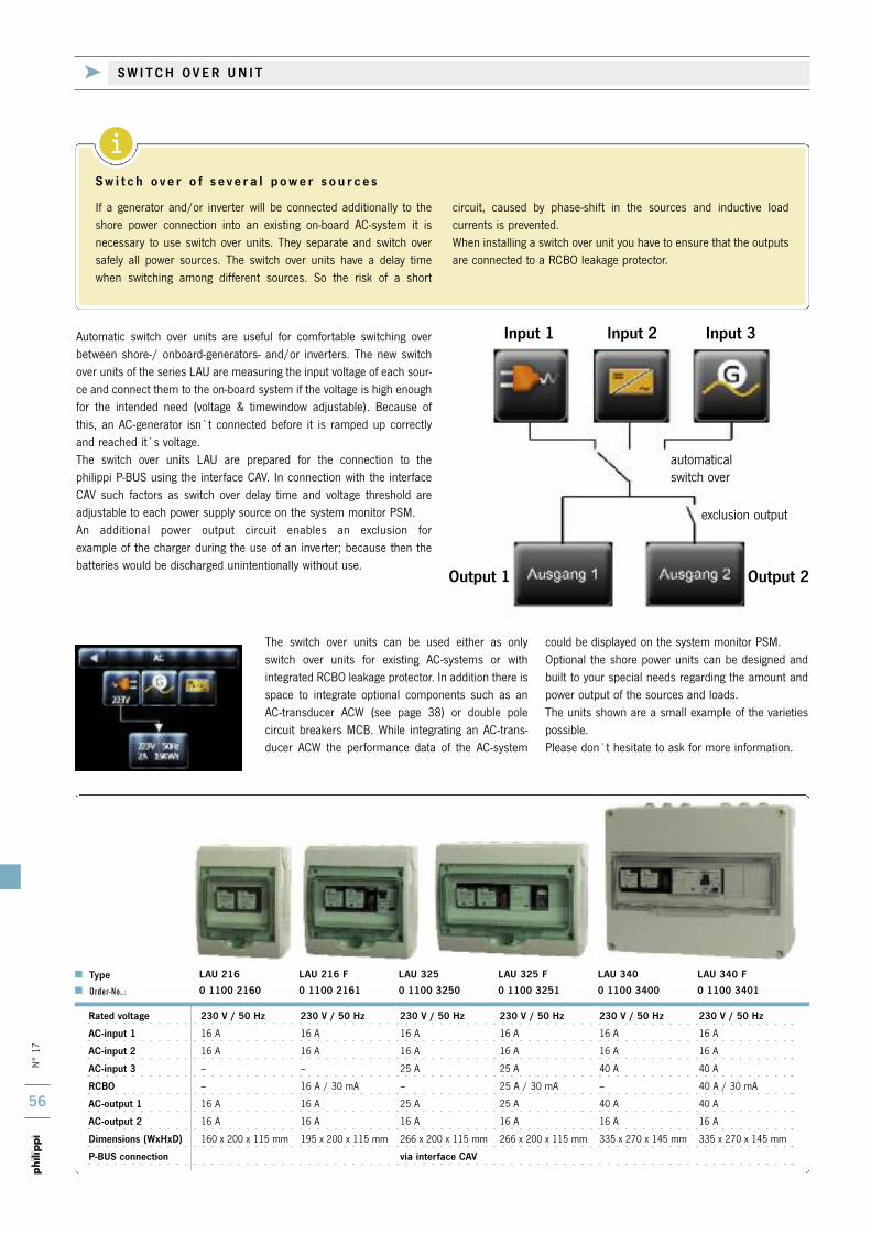
i
N° 17
56
automaticalswitch over
The switch over units can be used either as onlyswitch over units for existing AC-systems or with integrated RCBO leakage protector. In addition there isspace to integrate optional components such as anAC-transducer ACW (see page 38) or double pole circuit breakers MCB. While integrating an AC-trans-ducer ACW the performance data of the AC-system
could be displayed on the system monitor PSM.Optional the shore power units can be designed andbuilt to your special needs regarding the amount andpower output of the sources and loads. The units shown are a small example of the varietiespossible. Please don`t hesitate to ask for more information.
Rated voltage 230 V / 50 Hz 230 V / 50 Hz 230 V / 50 Hz 230 V / 50 Hz 230 V / 50 Hz 230 V / 50 Hz
AC-input 1 16 A 16 A 16 A 16 A 16 A 16 A
AC-input 2 16 A 16 A 16 A 16 A 16 A 16 A
AC-input 3 – – 25 A 25 A 40 A 40 A
RCBO – 16 A / 30 mA – 25 A / 30 mA – 40 A / 30 mA
AC-output 1 16 A 16 A 25 A 25 A 40 A 40 A
AC-output 2 16 A 16 A 16 A 16 A 16 A 16 A
Dimensions (WxHxD) 160 x 200 x 115 mm 195 x 200 x 115 mm 266 x 200 x 115 mm 266 x 200 x 115 mm 335 x 270 x 145 mm 335 x 270 x 145 mm
P-BUS connection via interface CAV
Type LAU 216 LAU 216 F LAU 325 LAU 325 F LAU 340 LAU 340 F
Order-No..: 0 1100 2160 0 1100 2161 0 1100 3250 0 1100 3251 0 1100 3400 0 1100 3401
Automatic switch over units are useful for comfortable switching over between shore-/ onboard-generators- and/or inverters. The new switchover units of the series LAU are measuring the input voltage of each sour-ce and connect them to the on-board system if the voltage is high enoughfor the intended need (voltage & timewindow adjustable). Because ofthis, an AC-generator isn`t connected before it is ramped up correctlyand reached it`s voltage. The switch over units LAU are prepared for the connection to the philippi P-BUS using the interface CAV. In connection with the interfaceCAV such factors as switch over delay time and voltage threshold areadjustable to each power supply source on the system monitor PSM. An additional power output circuit enables an exclusion for example of the charger during the use of an inverter; because then the batteries would be discharged unintentionally without use.
S w i t c h o v e r o f s e v e r a l p o w e r s o u r c e s
If a generator and/or inverter will be connected additionally to theshore power connection into an existing on-board AC-system it isnecessary to use switch over units. They separate and switch oversafely all power sources. The switch over units have a delay timewhen switching among different sources. So the risk of a short
circuit, caused by phase-shift in the sources and inductive load currents is prevented. When installing a switch over unit you have to ensure that the outputsare connected to a RCBO leakage protector.
k S W I T C H O V E R U N I T
Input 1 Input 2
Output 1 Output 2
Input 3
exclusion output

CAG 20 LG Leer CA
N° 17
57
k W AT E R T I G H T C O N N E C T O R F O R S H O R E P O W E R 2 3 0 V / 5 0 H Z
Max. load 63 A 63 A 63 A 63 A 63 AFront/Mounting depth 64 x 64/43 mm 64 x 64/56 mm 64 x 64/56 mm 64 x 64/81 mm 64 x 64/81 mm
Type CA 63 A 291 CA 63 A 211 LG CA 63 A 211 LW CA 63 A 251 CA 63 D 926
Order-No.: 6 4042 2910 6 4042 2110 6 4042 2111 6 4042 2510 6 4042 7980
Max. load 25 A 25 A 25 A 25 A 25 AFront/Mounting depth 48 x 48/44 mm 48 x 48/58 mm 48 x 48/58 mm 48 x 48/86 mm 48 x 48/86 mm
Type CH 16 A 291 CH 16 A 211 LG CH 16 A 211 LW CH 16 A 251 CH 16 D 926
Order-No.: 6 4020 2910 6 4020 2110 6 4020 2111 6 4020 2510 6 4020 7980
Switch Main switch Shore Generator Shore Inverter Shore Generator Inverter Shore Generator Inverter0-1 switch over 1-0-2 switch over 1-0-2 switch over 1-0-2-3 switch over 1-0-2-3, with limit on
use of charger while inverter op.
For assembly on frontplates with a max. thickness of 5 mm. Forbigger thickness pleaseuse blank panel CA.
Blank plate for easy mounting of a rotary selector switch of the series CH 16 forexample in a wooden wall. Delivery without rotary selector switch.
Dimensions W 70 x H 70 x D 3 mm
Leer CA Order-No.: 0 2900 2060
Manual switch over to select two feed lines (shore/genset), max. 25 A
Dimensions W 82 x H 92 x D 92 mm
CAG 20 LG Order-No.: 6 4120 2110
Stainless steel protective clamp to prevent
damage of angular mounted round plug of
the 692 series.
Identical to RS 692-Land GL/DK, but without angular housing (no picture).
Complete plug connector for shore power supply 230 V/50 Hz -16 A (2+PE). Includes coupling socket, flange plug, two protection caps and angular housing.
570 Order-No.: 0 0570 0000
RS 692 Land GL/DK Order-No.: 4 0692 3002
RS 692 Land GL Order-No.: 4 0692 3003
Complete plug connection forshore power connection230V/50Hz -16A "RS 692 Land"includes: coupling socket andflange plug (2 pole + PE), two pro-tective caps and angular housingwith compact dimensions.Ideal for space saving on board.Protective system - IP 67. To protect against inadvertentlydamaging of the coupling plugyou can use the stainless steelprotective clamp 570.Matching shore power cables youfind next page.
k R O TA R Y S E L E C T O R S W I T C H E S F O R A C 2 3 0 V

N° 17
58
The new MP16 shore power system has been designed to hook up yourboat quickly and easily. Based on the world standard CEE connectors thissystem offers a reliable and approved shore power connection. The corrosion resistance stainless steel power inlet adds to the finishingtouch of every boat. Easy locking waterproof cap (IP 56) .
Attention: normal CEE-couplingplugs cannot be used in connec-tion with the MP16-10!
Ready made yellow marine cordsets with watertight moulded con-nectors make these AC connectorsystem the perfect choice!Watertight and rugged.
Shore power organizer bag
MPB Order-No.: 7 0050 7021
Yellow watertight PUR - cable HO7BQ-F. Ideal forshore power cables. Details please see page 93.
H07BQ-F, 3x2,5 mm2 Order-No.: 7 0050 2530
Max. current 16A, tinned lines
H07BQ-F, 3x4 mm2 Order-No.: 7 0051 4030
Max. current 25A, tinned lines
H07BQ-F, 3x6 mm2 Order-No.: 7 0051 6030
Max. current 32A, tinned lines
Black weatherproof neopren isolated cableHO7RN-F, Details please see page 93.
H07RN-F, 3x2,5 mm2 Order-No.: 5 0730 2530
Max. current16A
H07RN-F, 3x2,5 mm2 50m No.: 5 2730 2530
Max. current 16A, cable 50m
Coupling plug for self mounting connecting
cable.(without indication-LED) 16A.
MPS 16-10 Order-No.: 7 0050 1611
Finished manufactured cable with moulded CEEcoupling plug and socket with protecting cap.Yellow weatherproof PUR cable type HO7BQ-F.
MPC 2.5-15 Order-No.: 7 0050 2821
Cable 3x2,5 mm2, 15m, for MP16/10
MPC 2.5-25 Order-No.: 7 0050 2822
Cable 3x2,5 mm2, 25m, for MP16/10
MPC 4-25 Order-No.: 7 0050 2832
Cable 3x4 mm2, 25m, for MP32/16, up to 25A
MPC 6-25 Order-No.: 7 0050 2838
Cable 3x6 mm2, 25m, for MP32/16, up to 32A
Coupling plug for self mounting connecting
cable.(without indication-LED) 32A.
MPS 32-16 Order-No.: 7 0050 3217
Flange plug with stainless steel housing 16A
Outer-l 87 mm, hole-l 48 mm, -depth 52 mm.
Flange plug with stainless steel housing 16A
Outer-l 107 mm, hole-l 75 mm, -depth 100 mm.
MP 16-10 Order-No.: 7 0050 1610
MP 32-16 Order-No.: 7 0050 3216
Integrated in the cord set connec-tor is a LED power indicator light.
k S H O R E P O W E R C O N N E C T O R S
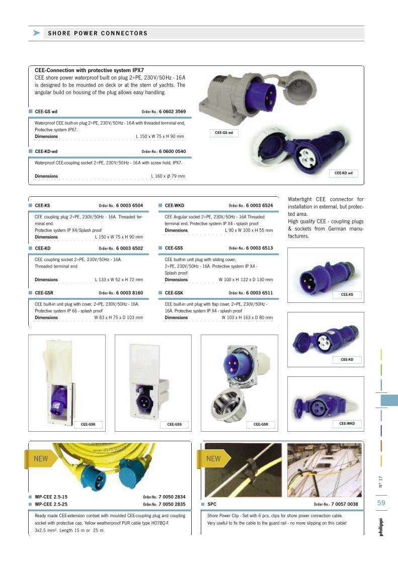
N° 17
59
NEW NEW
Watertight CEE connector forinstallation in external, but protec-ted area.High quality CEE - coupling plugs& sockets from German manu-facturers.
Ready made CEE-extension cordset with moulded CEE-coupling plug and coupling
socket with protective cap. Yellow weatherproof PUR cable type HO7BQ-F.
3x2,5 mm². Length 15 m or 25 m.
> MP-CEE 2.5-15 Order-No.: 7 0050 2834
> MP-CEE 2.5-25 Order-No.: 7 0050 2835
Shore Power Clip - Set with 6 pcs. clips for shore power connection cable.
Very useful to fix the cable to the guard rail - no more slipping on this cable!
> SPC Order-No.: 7 0057 0038
CEE coupling plug 2+PE, 230V/50Hz - 16A. Threaded ter-minal end.Protective system IP X4/Splash proofDimensions L 150 x W 75 x H 90 mm
CEE-KS Order-No.: 6 0003 6504
CEE coupling socket 2+PE, 230V/50Hz - 16A. Threaded terminal end
Dimensions L 133 x W 52 x H 72 mm
CEE-KD Order-No.: 6 0003 6502
CEE Angular socket 2+PE, 230V/50Hz - 16A Threaded terminal end. Protective system IP X4 - splash proofDimensions L 90 x W 100 x H 55 mm
CEE-WKD Order-No.: 6 0003 6524
CEE built-in unit plug with sliding cover, 2+PE, 230V/50Hz - 16A. Protective system IP X4 - Splash proofDimensions W 100 x H 122 x D 130 mm
CEE-GSS Order-No.: 6 0003 6513
CEE built-in unit plug with flap cover, 2+PE, 230V/50Hz -16A. Protective system IP X4 - splash proofDimensions W 103 x H 163 x D 80 mm
CEE built-in unit plug with cover, 2+PE, 230V/50Hz - 16A.Protective system IP 66 - splash proofDimensions W 83 x H 75 x D 103 mm
CEE-GSK Order-No.: 6 0003 6511 CEE-GSR Order-No.: 6 0003 8160
Waterproof CEE-coupling socket 2+PE, 230V/50Hz - 16A with screw hold, IPX7.
Dimensions L 160 x l 79 mm
@ CEE-KD-wd Order-No.: 6 0600 0540
Waterproof CEE built-on plug 2+PE, 230V/50Hz - 16A with threaded terminal end,Protective system IPX7. Dimensions L 150 x W 75 x H 90 mm
@ CEE-GS wd Order-No.: 6 0602 3569
CEE-Connection with protective system IPX7 CEE shore power waterproof built on plug 2+PE, 230V/50Hz - 16Ais designed to be mounted on deck or at the stern of yachts. Theangular build on housing of the plug allows easy handling.
CEE-GS wd
CEE-KD wd
CEE-GSSCEE-GSK CEE-GSR CEE-WKD
CEE-KD
CEE-KS
k S H O R E P O W E R C O N N E C T O R S

N° 17
60
i
To avoid galvanic currents between the hulland the shore power, a galvanic isolator canbe used. Two anti-parallel diodes in the line produce a voltage drop high enough to avoidgalvanic currents.
The galvanic isolator is also suited for yachtswith a GRP hull to avoid galvanic corrosion caused by the shore power connection to thepropulsion.
Waterproof sealed electronics in anodized aluminium
housing
Nominal current 16 A
Peak current 5000 A
Connection terminals 2 x M6
Dimensions (L x W x H) 200 x 120 x 60 mm
Weight 1 kg
GI 16 Order-No.: 7 0009 0016
RTR 25 230//230 0 6025 2323 230 V 230 V 2500 W 21 kg no yes
RTR 25 115//230 0 6025 1123 115 V 230 V 2500 W 21 kg no yes
RTR 25 230//115 0 6025 2311 230 V 115 V 2500 W 21 kg no yes
RTR 25 115-230//230 0 6025 1223 115/230 V 230 V 2500 W 21 kg yes yes
RTR 36 230//230 0 6036 2323 230 V 230 V 3600 W 27 kg no yes
RTR 36 115//230 0 6036 1123 115 V 230 V 3600 W 27 kg no yes
RTR 36 230//115 0 6036 2311 230 V 115 V 3600 W 27 kg no yes
RTR 36 115-230//230 0 6036 1223 115/230 V 230 V 3600 W 27 kg yes yes
Further models on request (Delivery time ca. 3 weeks)
Type Order-No.: Input - Output - Nominal Weight Input-voltage- Inrush current -
voltage voltage power switch over limiting
Isolating transformer with an electric potential 230/230 V allows a gal-vanic isolation of the shore power supply. To operate a network on board with 115 V by a shore power supply of 230 V, an electric transformer of 230/115 V is required.To operate an optional network with an electric potential of 115 V or 230 V on board a selector switch is used to divide the shore power supply.
Housing by salt water resistant aluminium with a plastic coating as surface protection for installation on a wall or the floor. Connection viainternal terminals. Inrush current protection by circuit breaker MCB 16A. Equipped as standard with a professional electronic soft start and inrushcurrent limiting ESB.Dimensions W 410 x D 290 x H 170 mm
G a l v a n i c C o r r o s i o n ( E l e c t r o l y s i s )
Corrosion is an ever present fact of life with boats. The mixing of saltwater and different metals is enough to cause galvanic corrosion. Allmetals when immersed in an electrically conductive fluid (called elec-trolyte) have a specific electrical potential. Given any two metalsimmersed in an electrolyte, when an electrical connection is madebetween them, the current flows from the higher-voltage metal to thelower-voltage metal. The current flowing through the electrolyte isgenerated by an electrochemical reaction that steadily consumes thelower-voltage metal (galvanic corrosion). This process will continue
until the metal with the lowest potential is used up. Corrosion willoccur, even if the metals are on different vessels. With the shorepower based electrical system we have a further nature of galvaniccorrosion. Many of these galvanic currents pass from one boat toanother, or to the dockside, down the grounding wire (green/yellow)of the AC shore power cord. This kind of galvanic couple is easily bro-ken with an isolation transformer on-board. The best solution is toinstall an isolation transformer, which will ensure that the shorepower connection is separated from the hull.
k G A LV A N I C I S O L AT O R
k I S O L AT I N G T R A N S F O R M E R

iN° 17
61
Bilge pump Loads
The heart of each DC- system are the batteries. Depending on the size ofthe boat, the intended use and the standard of comfort each system canbe very differently in size, but the basics are nearly the same:
starter battery only to start the engine ( AGM ) service or main battery for all other consumers (Gel) optional: battery in the bow for the bow thruster / windlass (AGM)
The capacity of the batteries should be high enough because of physio-chemical aspects you should use only 60% of the capacity of a battery in
order to avoid the premature failure of the battery. In any case a deepdischarging must be prevented.If you need several batteries in a bank (parallel connection) you shouldpay attention to the following points:- connect only batteries of the same type, size and age- diagonal current drawing (positive at battery 1, negative at battery 2)- same length of connection cables (+/-) between the batteries- for 24/36/48 V systems (serial connection) installation of one ormore BLA battery equalizer (see page 69) for charge equalisation.
In accordance with the European Standard (EN ISO 10133) a descrip-tion of electrical DC installation is given.An important point deals with the well known fuse protection of indivi-dual switch panel leads and all direct battery leads.One concept effectively places a main fuse as close as possible to thebattery. The large leads from the battery are capable of letting high currents through during a short circuit. This flow of energy between battery and leads can result in overhea-ting and eventually a fire!Even a starter battery stores enough energy to cause a fire in a yacht.That is why the main leads of a battery should not be too far away fromthe next mechanically protected fuse. The picture above shows theconcept of fuse protection to direct battery arrangements.
Every outgoing lead to switch panel, charger, windlass, instruments,heater, etc. must be fuse protected according to it`s cross-section. For example: If a switch panel receives a lead with a 16 mm², asshown on the diagram page 74, it has to be protected by a 50 A fuse.Smaller leads are connected to the fuses on the switch panel and aretherefore not to be considered during the connection of outgoing leadfuses. The battery main fuse switch is placed close to the battery tocut-off on board DC power supply.Loads such as bilge pumps, alarms, navigation instruments areconnected directly to the battery to prevent accidental cut off. Thesecross sections however, are also fuse protected. To protect these crosssections, ETA circuit breakers are suggested or as an alternative, astrip fuse may be set in (page 74f.).
The protection of electrical installations is one of the most important points of interest when dealing with security on board.
Service-batteries
Main switch
Fusing
Main switch
Starter-battery
Battery charger
Electr. diode splitter
Starter
Alternator
Terminal block
Power distribution panel
k B A S I C S O F T H E B AT T E R Y C O N N E C T I O N & P R O T E C T I O N
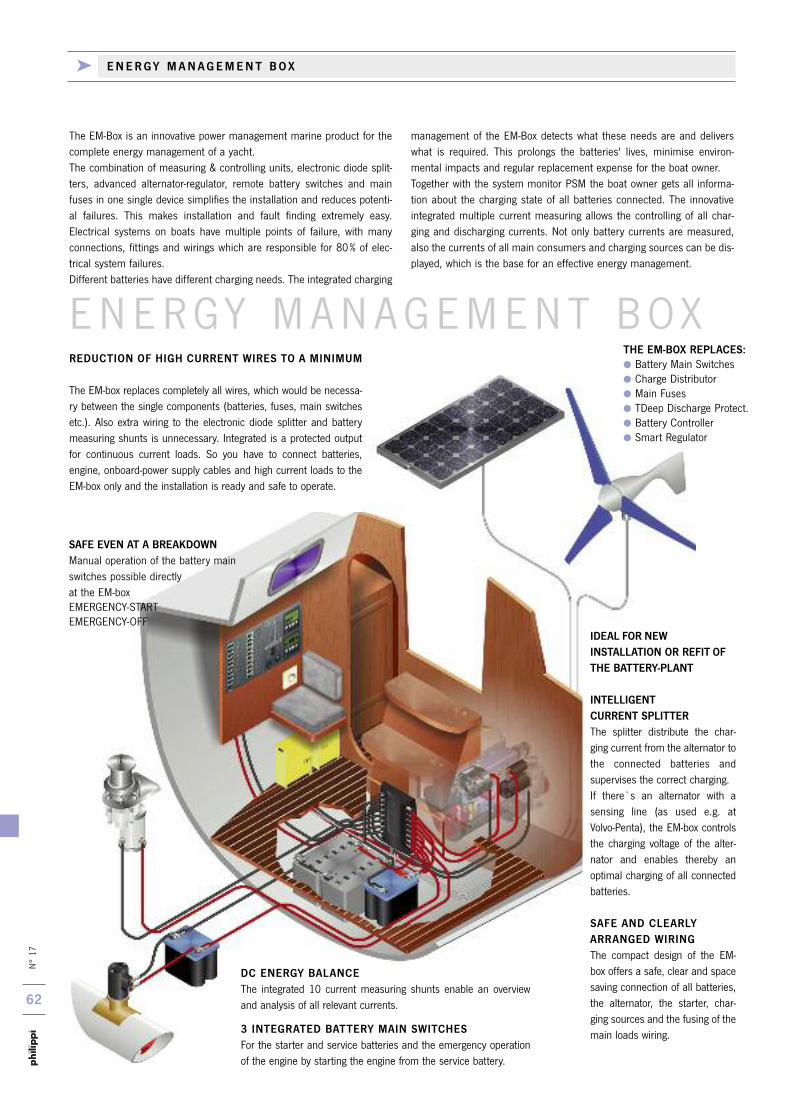
N° 17
62
REDUCTION OF HIGH CURRENT WIRES TO A MINIMUM
The EM-box replaces completely all wires, which would be necessa-ry between the single components (batteries, fuses, main switchesetc.). Also extra wiring to the electronic diode splitter and batterymeasuring shunts is unnecessary. Integrated is a protected outputfor continuous current loads. So you have to connect batteries, engine, onboard-power supply cables and high current loads to theEM-box only and the installation is ready and safe to operate.
DC ENERGY BALANCE The integrated 10 current measuring shunts enable an overviewand analysis of all relevant currents.
3 INTEGRATED BATTERY MAIN SWITCHESFor the starter and service batteries and the emergency operationof the engine by starting the engine from the service battery.
IDEAL FOR NEW INSTALLATION OR REFIT OFTHE BATTERY-PLANT
INTELLIGENTCURRENT SPLITTERThe splitter distribute the char-ging current from the alternator tothe connected batteries andsupervises the correct charging.If there`s an alternator with asensing line (as used e.g. atVolvo-Penta), the EM-box controlsthe charging voltage of the alter-nator and enables thereby anoptimal charging of all connectedbatteries.
SAFE AND CLEARLYARRANGED WIRINGThe compact design of the EM-box offers a safe, clear and spacesaving connection of all batteries,the alternator, the starter, char-ging sources and the fusing of themain loads wiring.
E N E RGY MANAGEMENT BOXTHE EM-BOX REPLACES: Battery Main Switches Charge Distributor Main Fuses TDeep Discharge Protect. Battery Controller Smart Regulator
SAFE EVEN AT A BREAKDOWNManual operation of the battery mainswitches possible directly at the EM-boxEMERGENCY-START EMERGENCY-OFF
The EM-Box is an innovative power management marine product for thecomplete energy management of a yacht.The combination of measuring & controlling units, electronic diode split-ters, advanced alternator-regulator, remote battery switches and mainfuses in one single device simplifies the installation and reduces potenti-al failures. This makes installation and fault finding extremely easy.Electrical systems on boats have multiple points of failure, with manyconnections, fittings and wirings which are responsible for 80% of elec-trical system failures.Different batteries have different charging needs. The integrated charging
management of the EM-Box detects what these needs are and deliverswhat is required. This prolongs the batteries' lives, minimise environ-mental impacts and regular replacement expense for the boat owner.Together with the system monitor PSM the boat owner gets all informa-tion about the charging state of all batteries connected. The innovative integrated multiple current measuring allows the controlling of all char-ging and discharging currents. Not only battery currents are measured,also the currents of all main consumers and charging sources can be dis-played, which is the base for an effective energy management.
k E N E R G Y M A N A G E M E N T B O X
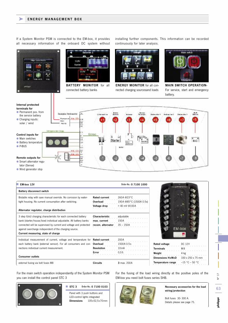
N° 17
63
Battery disconnect switch
Bistable relay with save manual override. No corrosion by water-
tight housing. No current consumption after switching.
Alternator regulator, charge distribution
3 step IUoU charging characteristic for each connected battery
bank (starter/house/bow) individual adjustable. All battery banks
connected will be supervised by current and voltage and protected
against overcharge independent of the charging source.
Current measuring, state of charge
Individual measurement of current, voltage and temperature for
each battery bank (external sensor). For all consumers and con-
nections individual current measurement.
Consumer outlets
external fusing via bolt fuses M8
Rated current 260A @23°C
Overload 190A @85°C (1500A 0.5s)
Voltage drop > 40 mV @100A
Characteristic adjustable
max. current 150A
recom. alternator 35 – 150A
Rated current 200A
Overload 1500A 0.5s
Resolution 10mA
Error 0,5%
Circuits 3 max. 200A
EM-box 12V Order-No.: 0 7100 1000
Necessary accessories for the loadwiring/protection
Bolt fuses 30- 300 A. Details please see page 75.
STC 3 Order-No.: 0 7100 0103
Panel with 3 push buttons andLED-control lights integratedDimensions 105x52,5x70mm
Rated voltage DC 12V
Terminals M8
Weight 4 kg
Dimensions HxWxD 330 x 250 x 75 mm
Temperature range –15 °C – 50 °C
For the main switch operation independantly of the System Monitor PSMyou can install the control panel STC 3
For the fusing of the load wiring directly at the positive poles of the EM-box you need bolt fuses series SHB.
BATTERY MONITOR for allconnected battery banks
ENERGY MONITOR for all con-nected charging sourcesand loads
MAIN SWITCH OPERATION-For service, start and emergencybattery.
If a System Monitor PSM is connected to the EM-box, it providesall necessary information of the onboard DC system without
installing further components. This information can be recordedcontinuously for later analysis.
Internal protected terminals for Permanent pos. from the service battery
Charging inputs:solar / wind
Control inputs for Main switches Battery temperature P-BUS
Remote outputs for Smart alternator regu-lator (Sense)
Wind generator stop
k E N E R G Y M A N A G E M E N T B O X
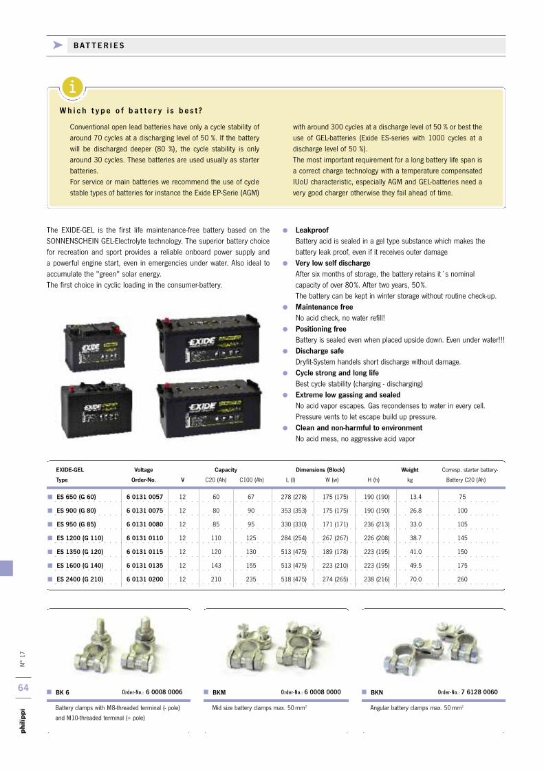
N° 17
64
i
ES 650 (G 60) 6 0131 0057 12 60 67 278 (278) 175 (175) 190 (190) 13.4 75
ES 900 (G 80) 6 0131 0075 12 80 90 353 (353) 175 (175) 190 (190) 26.8 100
ES 950 (G 85) 6 0131 0080 12 85 95 330 (330) 171 (171) 236 (213) 33.0 105
ES 1200 (G 110) 6 0131 0110 12 110 125 284 (254) 267 (267) 226 (208) 38.7 145
ES 1350 (G 120) 6 0131 0115 12 120 130 513 (475) 189 (178) 223 (195) 41.0 150
ES 1600 (G 140) 6 0131 0135 12 143 155 513 (475) 223 (210) 223 (195) 49.5 175
ES 2400 (G 210) 6 0131 0200 12 210 235 518 (475) 274 (265) 238 (216) 70.0 260
EXIDE-GEL Voltage Capacity Dimensions (Block) Weight Corresp. starter battery-
Type Order-No. V C20 (Ah) C100 (Ah) L (l) W (w) H (h) kg Battery C20 (Ah)
LeakproofBattery acid is sealed in a gel type substance which makes the battery leak proof, even if it receives outer damage
Very low self dischargeAfter six months of storage, the battery retains it´s nominal capacity of over 80%. After two years, 50%. The battery can be kept in winter storage without routine check-up.
Maintenance freeNo acid check, no water refill!
Positioning freeBattery is sealed even when placed upside down. Even under water!!!
Discharge safeDryfit-System handels short discharge without damage.
Cycle strong and long lifeBest cycle stability (charging - discharging)
Extreme low gassing and sealedNo acid vapor escapes. Gas recondenses to water in every cell. Pressure vents to let escape build up pressure.
Clean and non-harmful to environmentNo acid mess, no aggressive acid vapor
The EXIDE-GEL is the first life maintenance-free battery based on the SONNENSCHEIN GEL-Electrolyte technology. The superior battery choicefor recreation and sport provides a reliable onboard power supply and a powerful engine start, even in emergencies under water. Also ideal toaccumulate the "green" solar energy. The first choice in cyclic loading in the consumer-battery.
Angular battery clamps max. 50mm2
BKN Order-No.: 7 6128 0060
Mid size battery clamps max. 50mm2
BKM Order-No.: 6 0008 0000
Battery clamps with M8-threaded terminal (- pole)
and M10-threaded terminal (+ pole)
BK 6 Order-No.: 6 0008 0006
Conventional open lead batteries have only a cycle stability ofaround 70 cycles at a discharging level of 50 %. If the batterywill be discharged deeper (80 %), the cycle stability is onlyaround 30 cycles. These batteries are used usually as starterbatteries.For service or main batteries we recommend the use of cyclestable types of batteries for instance the Exide EP-Serie (AGM)
with around 300 cycles at a discharge level of 50 % or best theuse of GEL-batteries (Exide ES-series with 1000 cycles at adischarge level of 50 %). The most important requirement for a long battery life span isa correct charge technology with a temperature compensatedIUoU characteristic, especially AGM and GEL-batteries need avery good charger otherwise they fail ahead of time.
W h i c h t y p e o f b a t t e r y i s b e s t ?
k B AT T E R I E S
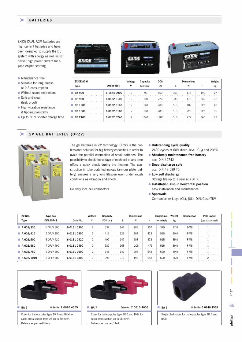
N° 17
65
A 602/335 6 OPzV 300 6 0131 0300 2 337 147 208 357 399 27.0 F-M8 1
A 602/415 5 OPzV 350 6 0131 0350 2 416 126 208 473 515 30.0 F-M8 1
A 602/500 6 OPzV 420 6 0131 0420 2 499 147 208 473 515 35.0 F-M8 1
A 602/580 7 OPzV 490 6 0131 0490 2 582 168 208 473 515 39.0 F-M8 1
A 602/750 6 OPzV 600 6 0131 0600 2 748 147 208 648 690 49.0 F-M8 1
A 602/1010 8 OPzV 800 6 0131 0800 2 998 212 193 648 690 66.0 F-M8 2
2V-GEL Type acc Voltage Capacity Dimensions Height incl. Weight Connection Pole layout
Type DIN 40742 Order-No. V K10 (Ah) L W H terminals kg (see data sheet)
The gel batteries in 2V technology (OPzV) is the pro-fessional solution for big battery-capacities in order toavoid the parallel connection of small batteries. Thepossibility to check the voltage of each cell at any timeoffers a quick check during the lifetime. The con-struction in tube plate technology (armour plate- bat-tery) ensures a very long lifespan even under roughconditions as vibration and shock.
Delivery incl. cell connectors.
Outstanding cycle quality2400 cycles at 60% disch. level (C10) and 20°C
Absolutely maintenance free batteryacc. DIN 40742
Deep discharge safeacc. DIN 43 539 T5
Low self dischargeStorage life up to 1 year at +30°C
Installation also in horizontal positioneasy installation and maintenance
ApprovalsGermanischer LIoyd (GL), (UL), DIN/Gost/TÜV
EXIDE DUAL AGM batteries arehigh current batteries and havebeen designed to supply the DCsystem with energy as well as todeliver high power current for agood engine starting.
Maintenance free Suitable for long breaks at 0 A consumption
Without space restrictions Safe and clean(leak proof)
High vibration resistance & tipping possibility
Up to 50 % shorter charge time
EK 920 6 1874 9900 12 92 860 353 175 190 27
EP 900 6 0132 0100 12 100 720 330 173 240 32
EP 1200 6 0132 0140 12 140 700 513 189 223 45
EP 1500 6 0132 0180 12 180 900 513 223 223 55
EP 2100 6 0132 0240 12 240 1200 518 279 240 72
EXIDE-AGM Voltage Capacity CCA Dimensions Weight
Type Order-No.: V K20 (Ah) (A) L W H kg
Cover for battery poles type BK 6 and BKM for
cable cross section from 25 up to 50 mm2.
Delivery as pair red/black.
Cover for battery poles type BK 6 and BKM for
cable cross section up to 95 mm2.
Delivery as pair red/black.
BA 5 Order-No.: 7 0010 4005 BA 7 Order-No.: 7 0010 4006
Single black cover for battery poles type BK 6 and
BKM
BA 6 Order-No.: 6 0140 4568
k 2 V G E L B AT T E R I E S ( O P Z V )
k B AT T E R I E S
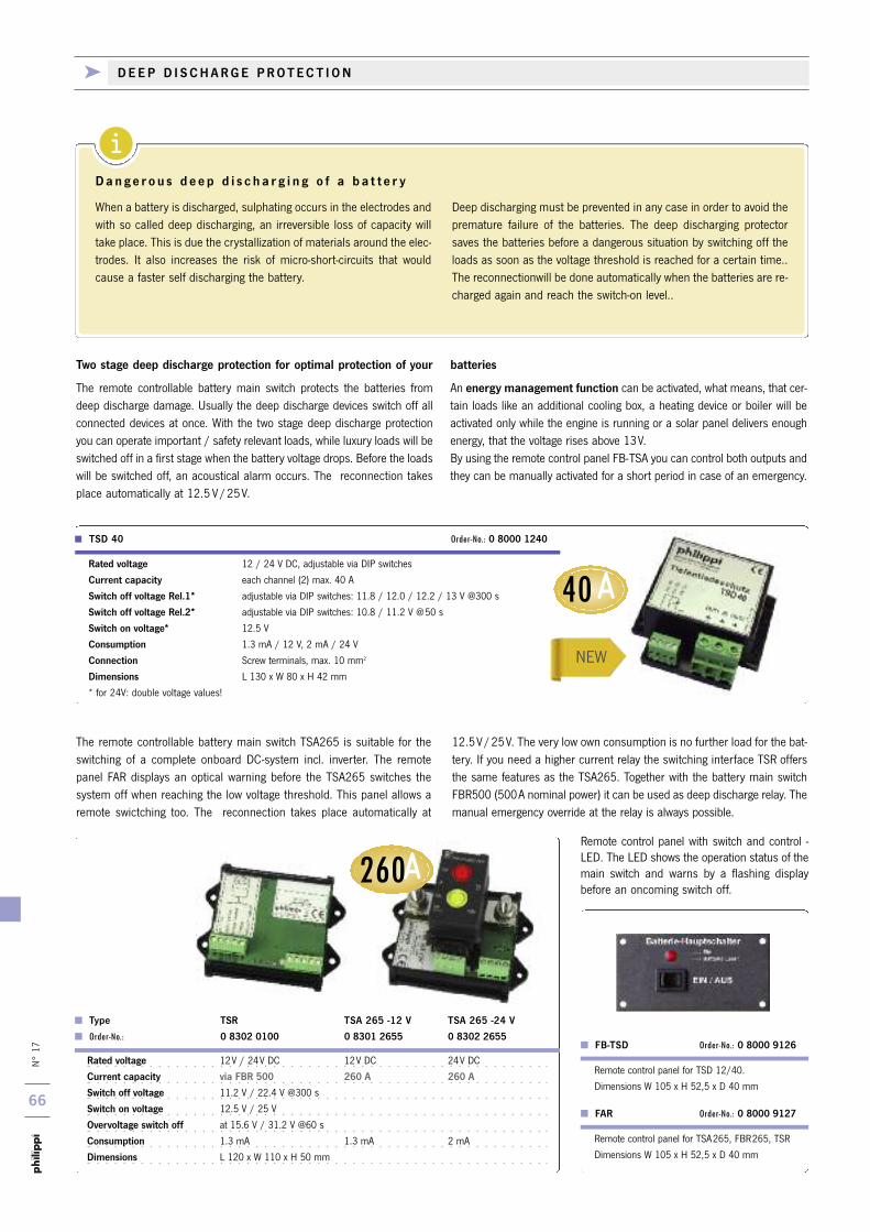
N° 17
66
i
A260
40A
NEW
k D E E P D I S C H A R G E P R O T E C T I O N
When a battery is discharged, sulphating occurs in the electrodes andwith so called deep discharging, an irreversible loss of capacity willtake place. This is due the crystallization of materials around the elec-trodes. It also increases the risk of micro-short-circuits that wouldcause a faster self discharging the battery.
Deep discharging must be prevented in any case in order to avoid thepremature failure of the batteries. The deep discharging protectorsaves the batteries before a dangerous situation by switching off theloads as soon as the voltage threshold is reached for a certain time..The reconnectionwill be done automatically when the batteries are re-charged again and reach the switch-on level..
D a n g e r o u s d e e p d i s c h a r g i n g o f a b a t t e r y
Rated voltage 12V / 24V DC 12V DC 24V DC
Current capacity via FBR 500 260 A 260 A
Switch off voltage 11.2 V / 22.4 V @300 s
Switch on voltage 12.5 V / 25 V
Overvoltage switch off at 15.6 V / 31.2 V @60 s
Consumption 1.3 mA 1.3 mA 2 mA
Dimensions L 120 x W 110 x H 50 mm
Remote control panel with switch and control -LED. The LED shows the operation status of themain switch and warns by a flashing displaybefore an oncoming switch off.
FAR Order-No.: 0 8000 9127
Remote control panel for TSD 12/40.
Dimensions W 105 x H 52,5 x D 40 mm
Remote control panel for TSA265, FBR265, TSR
Dimensions W 105 x H 52,5 x D 40 mm
The remote controllable battery main switch TSA265 is suitable for theswitching of a complete onboard DC-system incl. inverter. The remotepanel FAR displays an optical warning before the TSA265 switches thesystem off when reaching the low voltage threshold. This panel allows aremote swictching too. The reconnection takes place automatically at
12.5V/25V. The very low own consumption is no further load for the bat-tery. If you need a higher current relay the switching interface TSR offersthe same features as the TSA265. Together with the battery main switchFBR500 (500A nominal power) it can be used as deep discharge relay. Themanual emergency override at the relay is always possible.
The remote controllable battery main switch protects the batteries fromdeep discharge damage. Usually the deep discharge devices switch off allconnected devices at once. With the two stage deep discharge protectionyou can operate important / safety relevant loads, while luxury loads will beswitched off in a first stage when the battery voltage drops. Before the loadswill be switched off, an acoustical alarm occurs. The reconnection takesplace automatically at 12.5 V/25V.
An energy management function can be activated, what means, that cer-tain loads like an additional cooling box, a heating device or boiler will beactivated only while the engine is running or a solar panel delivers enoughenergy, that the voltage rises above 13V. By using the remote control panel FB-TSA you can control both outputs andthey can be manually activated for a short period in case of an emergency.
Two stage deep discharge protection for optimal protection of your batteries
Rated voltage 12 / 24 V DC, adjustable via DIP switches
Current capacity each channel (2) max. 40 A
Switch off voltage Rel.1* adjustable via DIP switches: 11.8 / 12.0 / 12.2 / 13 V @300 s
Switch off voltage Rel.2* adjustable via DIP switches: 10.8 / 11.2 V @50 s
Switch on voltage* 12.5 V
Consumption 1.3 mA / 12 V, 2 mA / 24 V
Connection Screw terminals, max. 10 mm2
Dimensions L 130 x W 80 x H 42 mm
* for 24V: double voltage values!
> TSD 40 Order-No.: 0 8000 1240
FB-TSD Order-No.: 0 8000 9126
Type TSR TSA 265 -12 V TSA 265 -24 V
Order-No.: 0 8302 0100 0 8301 2655 0 8302 2655
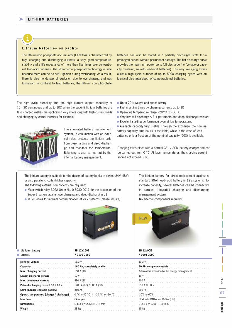
N° 17
67
i
Lithium - battery SB 12V160E SB 12V90E
Order-No.: 7 0101 2160 7 0101 2090
Nominal voltage 13.2 V 13.2 V
Capacity 160 Ah, completely usable 90 Ah, completely usable
Max. charging current 160 A (1C) Automatical limitation by the energy management
Lowest discharge voltage 10 V 10 V
Max. continuous current 480 A (3C) 200 A
Pulse discharging current 10 / 60 s. 1280 A (8C) / 800 A (5C) 350 A @ 30 s
EqPb (Equals lead-acid-battery) 350 Ah 200 Ah
Operat. temperature (charge / discharge) 0 °C to 45 °C / –20 °C to +60 °C -30ºC to 60ºC
Interface CAN-open Bluetooth, CAN-open, CI-Bus (LIN)
Dimensions L 413 x W 226 x H 314 mm L 353 x W 175x H 190 mm
Weight 28 kg 15 kg
Charging takes place with a normal GEL / AGM battery charger and canbe carried out from 0 °C. At lower temperatures, the charging currentshould not exceed 0.1C.
The lithium battery is suitable for the design of battery banks in series (24V, 48V)or also parallel circuits (higher capacity). The following external components are required: Main switch relay BDSA Order-No. 0 8930 0011 for the protection of the Super-B battery against overcharging and deep discharging v (
M12-Cables for internal communication at 24V systems (please inquire)
The lithium battery for direct replacement against astandard 90Ah lead- acid battery in 12V systems. Toincrease capacity, several batteries can be connectedin parallel. Integrated charging and dischargingmanagement system. No external components required!
The integrated battery managementsystem, in conjunction with an exter-nal relay, protects the lithium cellsfrom overcharging and deep dischar-ge and monitors the temperature.Balancing is also carried out by theinternal battery management.
The high cycle durability and the high current output capability of 1C - 3C continuous and up to 10C when the super-B lithium batteries arefast- charged makes the application very interesting with high-current loadsand charging by combi-inverters for example.
Up to 70 % weight and space saving Fast charging times by charging currents up to 1C Operating temperature range –20°C to +60°C Very low self discharge < 3 % per month and deep discharge-resistant Excellent starting performance even at low temperatures Available capacity fully usable. Through the exchange, the nominal battery capacity amp hours is available, while in the case of lead batteries only a fraction of the nominal capacity (60%) is available.
The lithium-iron phosphate accumulator (LiFePO4) is characterized byhigh charging and discharging currents, a very good temperature-stability and a life expectancy of more than five times over conventio-nal lead-acid batteries. The lithium-iron phosphate technology is safebecause there can be no self - ignition during overheating. As a result,there is also no danger of explosion due to overcharging and gas formation. In contrast to lead batteries, the lithium iron phosphate
batteries can also be stored in a partially discharged state for a prolonged period, without permanent damage. The flat discharge curveprovides the maximum power up to full discharge (no "voltage or capa-city break-in", as with lead-acid batteries). The very low aging lossesallow a high cycle number of up to 5000 charging cycles with an identical discharge depth of comparable gel batteries.
L i t h i u m b a t t e r i e s o n y a c h t s
NEW
k L I T H I U M B AT T E R I E S
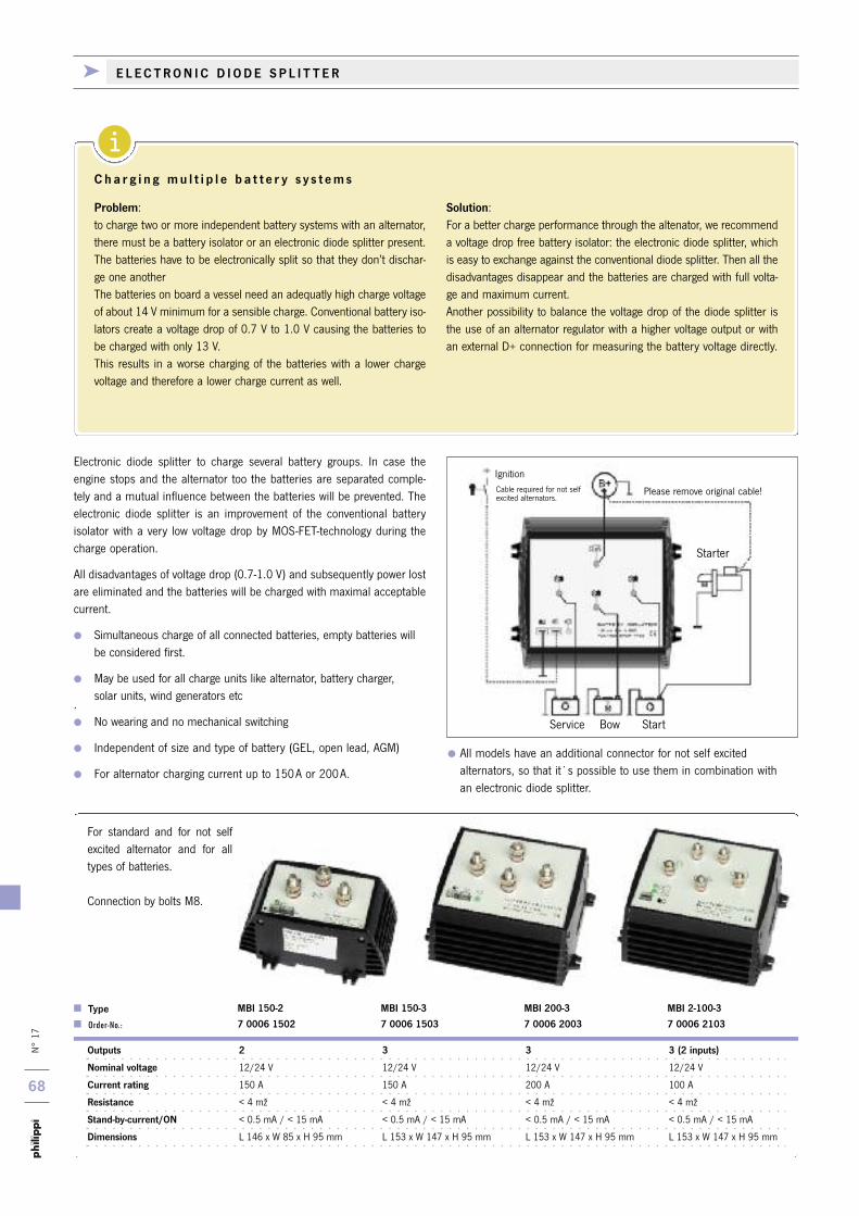
N° 17
68
i
k E L E C T R O N I C D I O D E S P L I T T E R
Outputs 2 3 3 3 (2 inputs)
Nominal voltage 12/24 V 12/24 V 12/24 V 12/24 V
Current rating 150 A 150 A 200 A 100 A
Resistance < 4 mž < 4 mž < 4 mž < 4 mž
Stand-by-current/ON < 0.5 mA / < 15 mA < 0.5 mA / < 15 mA < 0.5 mA / < 15 mA < 0.5 mA / < 15 mA
Dimensions L 146 x W 85 x H 95 mm L 153 x W 147 x H 95 mm L 153 x W 147 x H 95 mm L 153 x W 147 x H 95 mm
Type MBI 150-2 MBI 150-3 MBI 200-3 MBI 2-100-3
Order-No.: 7 0006 1502 7 0006 1503 7 0006 2003 7 0006 2103
Service Bow Start
Starter
Please remove original cable!
IgnitionCable required for not selfexcited alternators.
Electronic diode splitter to charge several battery groups. In case the engine stops and the alternator too the batteries are separated comple-tely and a mutual influence between the batteries will be prevented. The electronic diode splitter is an improvement of the conventional battery isolator with a very low voltage drop by MOS-FET-technology during thecharge operation.
All disadvantages of voltage drop (0.7-1.0 V) and subsequently power lostare eliminated and the batteries will be charged with maximal acceptablecurrent.
Simultaneous charge of all connected batteries, empty batteries will be considered first.
May be used for all charge units like alternator, battery charger, solar units, wind generators etc
. No wearing and no mechanical switching
Independent of size and type of battery (GEL, open lead, AGM)
For alternator charging current up to 150A or 200A.
All models have an additional connector for not self excitedalternators, so that it`s possible to use them in combination with an electronic diode splitter.
For standard and for not selfexcited alternator and for alltypes of batteries.
Connection by bolts M8.
Problem:to charge two or more independent battery systems with an alternator,there must be a battery isolator or an electronic diode splitter present.The batteries have to be electronically split so that they don’t dischar-ge one another The batteries on board a vessel need an adequatly high charge voltageof about 14 V minimum for a sensible charge. Conventional battery iso-lators create a voltage drop of 0.7 V to 1.0 V causing the batteries tobe charged with only 13 V.This results in a worse charging of the batteries with a lower charge voltage and therefore a lower charge current as well.
Solution:For a better charge performance through the altenator, we recommenda voltage drop free battery isolator: the electronic diode splitter, whichis easy to exchange against the conventional diode splitter. Then all thedisadvantages disappear and the batteries are charged with full volta-ge and maximum current.Another possibility to balance the voltage drop of the diode splitter isthe use of an alternator regulator with a higher voltage output or withan external D+ connection for measuring the battery voltage directly.
C h a r g i n g m u l t i p l e b a t t e r y s y s t e m s
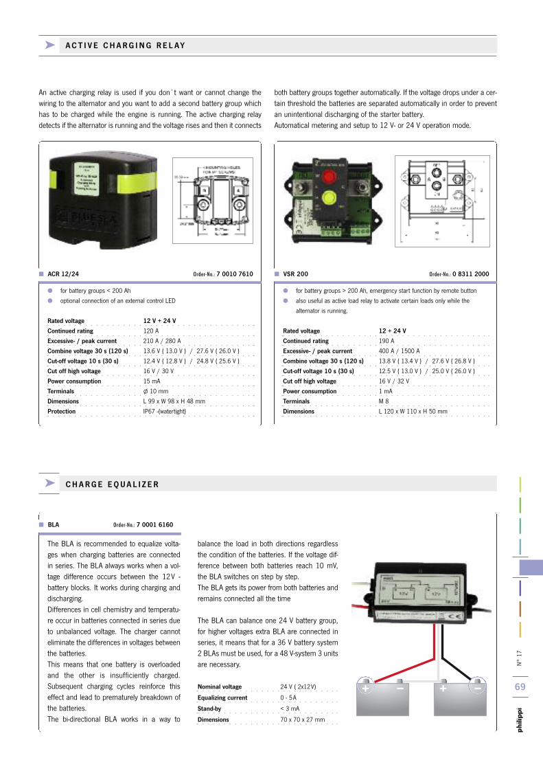
N° 17
69
k C H A R G E E Q U A L I Z E R
for battery groups < 200 Ah
optional connection of an external control LED
Rated voltage 12 V + 24 V
Continued rating 120 A
Excessive- / peak current 210 A / 280 A
Combine voltage 30 s (120 s) 13.6 V ( 13.0 V ) / 27.6 V ( 26.0 V )
Cut-off voltage 10 s (30 s) 12.4 V ( 12.8 V ) / 24.8 V ( 25.6 V )
Cut off high voltage 16 V / 30 V
Power consumption 15 mA
Terminals l 10 mm
Dimensions L 99 x W 98 x H 48 mm
Protection IP67 -(watertight)
ACR 12/24 Order-No.: 7 0010 7610
for battery groups > 200 Ah, emergency start function by remote button
also useful as active load relay to activate certain loads only while the
alternator is running.
Rated voltage 12 + 24 V
Continued rating 190 A
Excessive- / peak current 400 A / 1500 A
Combine voltage 30 s (120 s) 13.8 V ( 13.4 V ) / 27.6 V ( 26.8 V )
Cut-off voltage 10 s (30 s) 12.5 V ( 13.0 V ) / 25.0 V ( 26.0 V )
Cut off high voltage 16 V / 32 V
Power consumption 1 mA
Terminals M 8
Dimensions L 120 x W 110 x H 50 mm
VSR 200 Order-No.: 0 8311 2000
An active charging relay is used if you don`t want or cannot change thewiring to the alternator and you want to add a second battery group whichhas to be charged while the engine is running. The active charging relaydetects if the alternator is running and the voltage rises and then it connects
both battery groups together automatically. If the voltage drops under a cer-tain threshold the batteries are separated automatically in order to preventan unintentional discharging of the starter battery. Automatical metering and setup to 12 V- or 24 V operation mode.
balance the load in both directions regardlessthe condition of the batteries. If the voltage dif-ference between both batteries reach 10 mV,the BLA switches on step by step.The BLA gets its power from both batteries andremains connected all the time
The BLA can balance one 24 V battery group,for higher voltages extra BLA are connected inseries, it means that for a 36 V battery system2 BLAs must be used, for a 48 V-system 3 unitsare necessary.
Nominal voltage 24 V ( 2x12V)
Equalizing current 0 - 5A
Stand-by < 3 mA
Dimensions 70 x 70 x 27 mm
The BLA is recommended to equalize volta-ges when charging batteries are connectedin series. The BLA always works when a vol-tage difference occurs between the 12V -battery blocks. It works during charging anddischarging.Differences in cell chemistry and temperatu-re occur in batteries connected in series dueto unbalanced voltage. The charger cannoteliminate the differences in voltages betweenthe batteries. This means that one battery is overloadedand the other is insufficiently charged.Subsequent charging cycles reinforce thiseffect and lead to prematurely breakdown ofthe batteries.The bi-directional BLA works in a way to
BLA Order-No.: 7 0001 6160
k A C T I V E C H A R G I N G R E L AY
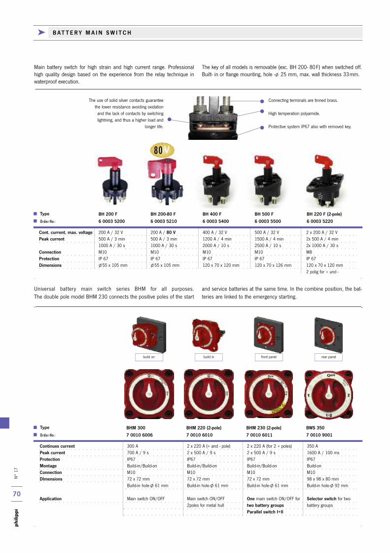
N° 17
70
80V
k B AT T E R Y M A I N S W I T C H
Cont. current, max. voltage 200 A / 32 V 200 A / 80 V 400 A / 32 V 500 A / 32 V 2 x 200 A / 32 VPeak current 500 A / 3 min 500 A / 3 min 1200 A / 4 min 1500 A / 4 min 2x 500 A / 4 min
1000 A / 30 s 1000 A / 30 s 2000 A / 10 s 2500 A / 10 s 2x 1000 A / 30 sConnection M10 M10 M10 M10 M8Protection IP 67 IP 67 IP 67 IP 67 IP 67Dimensions l55 x 105 mm l55 x 105 mm 120 x 70 x 120 mm 120 x 70 x 126 mm 120 x 70 x 120 mm
2 polig for + und -
Type BH 200 F BH 200-80 F BH 400 F BH 500 F BH 220 F (2-pole) Order-No.: 6 0003 5200 6 0003 5210 6 0003 5400 6 0003 5500 6 0003 5220
Main battery switch for high strain and high current range. Professional high quality design based on the experience from the relay technique inwaterproof execution.
The key of all models is removable (exc. BH 200- 80F) when switched off.Built- in or flange mounting, hole -l 25 mm, max. wall thickness 33mm.
Continues current 300 A 2 x 220 A (+ and - pole) 2 x 220 A (for 2 + poles) 350 A Peak current 700 A / 9 s 2 x 500 A / 9 s 2 x 500 A / 9 s 1600 A / 100 ms Protection IP67 IP67 IP67 IP67Montage Build-in/Build-on Build-in/Build-on Build-in/Build-on Build-onConnection M10 M10 M10 M10DImensions 72 x 72 mm 72 x 72 mm 72 x 72 mm 98 x 98 x 80 mm
Build-in hole-l 61 mm Build-in hole-l 61 mm Build-in hole-l 61 mm Build-in hole-l 92 mm
Application Main switch ON/OFF Main switch ON/OFF One main switch ON/OFF for Selector switch for two-2poles for metal hull two battery groups battery groups
Parallel switch I+II
Type BHM 300 BHM 220 (2-pole) BHM 230 (2-pole) BWS 350 Order-No.: 7 0010 6006 7 0010 6010 7 0010 6011 7 0010 9001
Universal battery main switch series BHM for all purposes. The double pole model BHM 230 connects the positive poles of the start
and service batteries at the same time. In the combine position, the bat-teries are linked to the emergency starting.
The use of solid silver contacts guaranteethe lower resistance avoiding oxidationand the lack of contacts by switchinglightning, and thus a higher load and
longer life.
Connecting terminals are tinned brass.
High temperation polyamide.
Protective system IP67 also with removed key.
build on build in front panel rear panel

N° 17
71
k B AT T E R Y M A I N S W I T C H k R E L AY
k R E M O T E B AT T E R Y M A I N S W I T C H
Key operated switch (0-1) for remote control of
FBR 265. The key can be withdrawn in off position.
Rated current 10 A, Mounting hole l 22 mm
Remote control switch (0-1) with LED state indicator
for remote control main switch FBR 265 and
TSA 265.
Matching mounting panel: Panel 711
Order-No.: 0 2990 7110 (please order separately)
CG 4 A 200 Order-No.: 6 4004 2001 RCS 0-1 Order-No.: 7 0010 2155
The installation of a remote control main switch has several advantages:the safe and comfortable switching from a well accessible place which iseasy to reach also in case of an emergency. The wiring system benefits
from an installation of the main switch near the battery. Thus the voltagedrop by longer wires will be avoided and the system works optimal.
Bi-stable remote battery switch with manual override knob. Protection IP 66.
Remote control switch incl. in delivery.
Matching panel for remote switch: panel 711 (please order separately).
Rated voltage 12 V or 24 V
Live Current Rating 500 A @ 20°C, 95 mm2
Intermittent / Cranking Rating 2500 A / 5 s
Consumption 0 mA
Terminal stud size 3/8"-16 (M10)
Dimensions W 139 x H 95 x D 53 mm
Bistable main switch relay with integrated electronic control and LED status indica-
tion. Operation via external switch 0-1 or remote control panel FAR (page 66).
Important: in case of an emergency you can switch the relay manually!
Rated Voltage DC 12 V + 24 V
Live Current Rating DC 260 A @ 20°C, 50 mm2
Intermittent / Cranking Rating DC 400A/5s, 1500 A/0,2s
Operating Current 1 mA
Dimensions, Terminal L 120 x W 110 x H 50 mm, M8
Protection IP 54
FBR 265 Order-No.: 0 8302 2650
FBR 500 -12 Order-No.: 7 0010 7700
FBR 500 -24 Order-No.: 7 0010 7702
Continuous current 140 A 140 AInstallation Flange fitting Directly on batteryConnection M10 M10Dimensions 116 x l 64 mm 116 x l 64 mm
Hole-l 25 mm
Type BH 1000 F BH 1000 B Order-No.: 7 6210 0840 7 6210 0842
Battery main switchfor low-cost applica-tion. Both models with removable key whenswitched off.
Battery isolation relay for small battery plants or general use.
Coil 12 V / 1,8 W 12 V / 1,8 W 24 V / 1,8 W
Current 40 A 50 (70) A 50 (70) A
Connection Flat term. 6.3 mm Flat terminals 9.6 mm / 6.3 mm
Dimensions W 32 x L 29 x H 59 mm
Type REL 40 -12 V TR 70 -12 V TR 70 -24 V
Order-No.: 0 5999 2012 0 8000 7012 0 8000 7024

1170
FSS
1610
SKL-B
ø4
AUS
738
6,4
18,8
N° 17
72
Supply lines of bilge pump, alarm systems and lines for voltage and current measurement devices have to be protected by thermal fuses or -better - thermal circuit breakers. They must be installed as close as
possible to the batteries.The circuit breakers of the series E-T-A 1610 andE-T-A 1170 are the best solution due to the easy plugging possibility.
Fuseholder for circuit breaker or blade fuse to pro-
tect e.g. voltage measuring lines. Flat terminals 6,3
mm.
ASH 1 Order-No.: 6 0030 0341
FSS-Set Order-No: 6 0060 0418
1170-01-8A Order-No: 1 1170 0008
1170-01-15A Order-No: 1 1170 0015
1170-01-25A Order-No: 1 1170 0025
1610-21-5A Order-No: 1 1610 2005
1610-21-10A Order-No: 1 1610 2010
1610-21-15A Order-No: 1 1610 2015
1610-21-20A Order-No: 1 1610 2020
1610-21-25A Order-No: 1 1610 2025
1610-21-30A Order-No: 1 1610 2030
Set of 10 (3A / 5A / 7.5A / 2x10A / 15A / 2x 20A / 25A / 30A) different blade fuses in package.
Compact single pole thermal circuit breaker withpush-to-reset, failsafe, trip free, snap on mecha-nism and separate manual release. Combiningfull feature circuit breaker protection and conve-nient low cost of ownership benefit. Fitted withblade terminals for plug-in mounting and retainingclips. Rated voltage DC 28 V. Special socketsavailable (see below).
Compact single pole thermal circuit breaker withpush-to-reset, failsafe, trip free, snap actionmechanism. Fitted with blade terminals and retai-ning clips, for plug-in mounting . Rated voltageDC 28 V. Special sockets available (see below).
Rail (35 mm), length 1m
NS 35/7.5 Order-No.: 6 2080 1733
Dimensions L 120 x W 44 x H 24 mm
Plug in safe guard clamps for 6/8 circuit breakers E-T-A 1610 or E-T-A 1170. Connection with flat ter-minals. Transparent cover is included. Fuses have tobe ordered separately (see above)
Dimensions L 100 x W 44 x H 24 mm
ASH 8 Order-No.: 6 0010 0590
ASH 6 Order-No.: 6 0010 0600
Connecting band (10-poles, separable) for SKL
SKL-B Order-No.: 1 2222 3201
SKL Order-No.: 1 2222 3301
Bridgeable safeguard clamp for circuit breakers E-T-A 1610 or E-T-A 1170. For DIN rail assembly,connection over flat pin 6.3 mm.
Dimensions L 65 x H 47 x W 8 mm
Plug-in socket attachable on a rail (35 mm) orfor mounting on a flat surface. For circuit breakertypes E-T-A 1170 und 1610. Connection withflat terminals 6,3 mm.
Dimensions W 12,7 x H 47 x D 58 mm.
12-P10 Order-No.: 1 1170 9000
k P R O T E C T I O N O F S M A L L L O A D S

13,5 AUS 3/8-27UNS-2A
27,6
9,5
19
A
1 4 3 2
22,5 AUS
29
46,5
IG1=3/8-27UNS-2A
10,4
N° 17
73
i
ASM 6 Order-No.: 7 0010 5025
ASM 12 Order-No.: 7 0010 5026
Fuse holder for 6 (12) blade fuses and common connection for all slots and in addition negative terminals. Lug terminals l 6 mm facilitate installation. Included is an easy removable transparent cover with label boxes and storage fortwo spare fuses. Maximum current per circuit 30 A, (total 100 A)
Dimensions ASM 6 L 125 x W 84 x H 39 mm
Dimensions ASM 12 L 165 x W 84 x H 39 mm
ASB 6 Order-No.: 7 0010 5028
Fuse holder for 6 blade fuses. Common potential for all slot connections. Lug terminals l 6 mm facilitate the installation. Included is an easy removable transparent cover with label boxes and storage for two spare fuses. Maximum current per circuit. 30 A, (total 100 A).
Single pole thermal circuit breaker with press-to-reset, failsafe, trip-free, snap action mechanism. For panel mounting l 10 mm. Protection caps(optional) particularly available for high humidityand other damp conditions.(see page 75)Rated voltage DC 28 V, AC 250 V. Current ratings6...25 A.Circuit breakers available ex stock
2-5700-IG1-K10-DD-6A No.: 1 2570 0006
2-5700-IG1-K10-DD-8A No.: 1 2570 0008
2-5700-IG1-K10-DD-10A No.: 1 2570 0010
2-5700-IG1-K10-DD-12A No.: 1 2570 0012
2-5700-IG1-K10-DD-16A No.: 1 2570 0016
2-5700-IG1-K10-DD-20A No.: 1 2570 0020
2-5700-IG1-K10-DD-25A No.: 1 2570 0025
E-T-A 2-5700-IG1-K10-DD
Miniaturised single pole thermal circuit breakerwith push-to-reset failsafe, trip-free, snap onmechanism (R-type TO CBE to EN 60934). Panelmounting. Fitting hole l12 mm. Rated voltage DC 28 V, AC 250 V. Current ratings 10A...16 AWidth 11 mm.Available ex stock:
1140-G111-P1M1-10A No.: 1 1141 0010
1140-G111-P1M1-16A No.: 1 1141 0016
E-T-A 1140-G111-P1M1
The use of a circuit breaker instead ofa main switch and separate fuse hasfollowing advantages:
= Less space required, because onlyone item.
= Much easier and faster installa-tion, because no additional wire between switch and fuse is required.
= No change of the fuse after a short.
= The cost of a circuit breaker isn`thigher than for a main switch andhigh power fuse.
W h y u s i n g a
c i r c u i t b r e a k e r ?
k F U S E B L O C K S U P T O 3 0 A
k T H E R M A L C I R C U I T B R E A K E R F O R C U R R E N T S U P T O 2 5 A

i
N° 17
74
k F U S E S & F U S E B L O C K S U P T O 1 2 5 A
MIDI Strip fuse up to 125A.Nominal voltage 32V. Fixing hole distance 30 mm.Dimensions W 42 x H 12 x D 8 mm
Safety fuse block for MIDI- fuses STM up to 125A. Max. 32V with watertight and ignition protected cover IP 66. Terminal stud size M8. Please order fuses separately!
Dimensions L 127 x W 47 x H 41 mm
Safety hub fuse block with integrated negative busbar for small to medium sizeyachts. 4 MIDI fuses type STM (25-125 A) and 6 blade fuses type FSS (1- 25A).Watertight and ignition protected cover provides storage space for 4 spare fuses.Please order fuses separately!
Dimensions L 165 x W 129 x H 48 mm
Small fuse holder for MIDI strip fuses up to 50A .Especially for the protection of lines up to 10 mm2. Connecting terminals M5.
Dimensions L 70 x W 50 x H 22 mm
SHN 1 Order-No.: 7 0010 7720
STM 30 Order-No.: 6 5631 5301
STM 40 Order-No.: 6 5631 5401
STM 50 Order-No.: 6 5631 5501
STM 60 Order-No.: 6 5631 5601
STM 80 Order-No.: 6 5631 5801
STM 100 Order-No.: 6 5631 5901
STM 125 Order-No.: 6 5631 6001
SHF 150 Order-No.: 7 0010 7748
SHM 1 Order-No.: 6 5631 0001
Single Conductor refering to “Germanischer Lloyd“
Conductor-Cross Current Rating Recommended Circuit SectionArea Breaker Rating
mm2 amps amps
1.5 12 10
2.5 17 16
4 23 20
6 29 25
10 40 35
16 54 50
25 71 60
35 87 80
50 105 100
70 135 125
95 165 160
P r o t e c t i o n o f o n b o a r d i n s t a l l a t i o n
An electrical fire is a terrifying situation at anytime, but on board a boat consequences can be catastrophic. E-T-A circuit breakers are designed tominimize the danger of fires in electrical wiring and systems by providing efficient and reliable protection against overload and short circuit condi-tions.At the same time E-T-A circuit breakers are conveniently resetable once thefault has been corrected. This eliminates the need of replacement fuses or the risk of fitting unsuitable temporary fuse replacement. The problems of corrosion and fatigue often associated with fuses are also eliminated. In addition, nearly all circuit breakers on the following pages may be ope-rated as switches.It is particulary important to be sure that the current rating selected for thecircuit breakers is not greater than the current rating of the cables. As a general guide the adjacent table (Germanischer Lloyd) may be followed forsingle conductors in well ventilated areas.
Fuse blocks are useful for loads which don`t need an extra switching function from the distribution panel. They provide a clear,compact and reasonable priced solution for smaller boats or additional requirements.
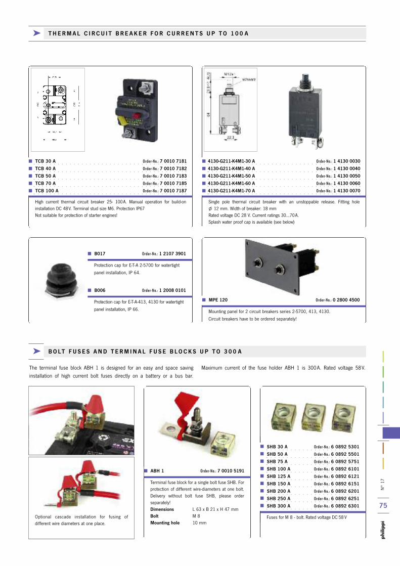
N° 17
75
Protection cap for E-T-A-413, 4130 for watertight
panel installation, IP 66.
B006 Order-No.: 1 2008 0101
Protection cap for E-T-A 2-5700 for watertight
panel installation, IP 64.
Mounting panel for 2 circuit breakers series 2-5700, 413, 4130.
Circuit breakers have to be ordered separately!
B017 Order-No.: 1 2107 3901
MPE 120 Order-No.: 0 2800 4500
High current thermal circuit breaker 25- 100A. Manual operation for build-on installation DC 48V. Terminal stud size M6. Protection IP67Not suitable for protection of starter engines!
TCB 30 A Order-No.: 7 0010 7181
TCB 40 A Order-No.: 7 0010 7182
TCB 50 A Order-No.: 7 0010 7183
TCB 70 A Order-No.: 7 0010 7185
TCB 100 A Order-No.: 7 0010 7187
Single pole thermal circuit breaker with an unstoppable release. Fitting hole l 12 mm. Width of breaker: 18 mmRated voltage DC 28 V. Current ratings 30...70A.Splash water proof cap is available (see below)
4130-G211-K4M1-30 A Order-No.: 1 4130 0030
4130-G211-K4M1-40 A Order-No.: 1 4130 0040
4130-G211-K4M1-50 A Order-No.: 1 4130 0050
4130-G211-K4M1-60 A Order-No.: 1 4130 0060
4130-G211-K4M1-70 A Order-No.: 1 4130 0070
SHB 30 A Order-No.: 6 0892 5301 SHB 50 A Order-No.: 6 0892 5501 SHB 75 A Order-No.: 6 0892 5751 SHB 100 A Order-No.: 6 0892 6101 SHB 125 A Order-No.: 6 0892 6121 SHB 150 A Order-No.: 6 0892 6151 SHB 200 A Order-No.: 6 0892 6201 SHB 250 A Order-No.: 6 0892 6251 SHB 300 A Order-No.: 6 0892 6301
Fuses for M 8 - bolt. Rated voltage DC 58 V
ABH 1 Order-No.: 7 0010 5191
Terminal fuse block for a single bolt fuse SHB. Forprotection of different wire-diameters at one bolt.Delivery without bolt fuse SHB, please order separately!Dimensions L 63 x B 21 x H 47 mmBolt M 8Mounting hole 10 mm
Optional cascade installation for fusing of different wire diameters at one place.
k B O LT F U S E S A N D T E R M I N A L F U S E B L O C K S U P T O 3 0 0 A
The terminal fuse block ABH 1 is designed for an easy and space saving installation of high current bolt fuses directly on a battery or a bus bar.
Maximum current of the fuse holder ABH 1 is 300A. Rated voltage 58V.
k T H E R M A L C I R C U I T B R E A K E R F O R C U R R E N T S U P T O 1 0 0 A
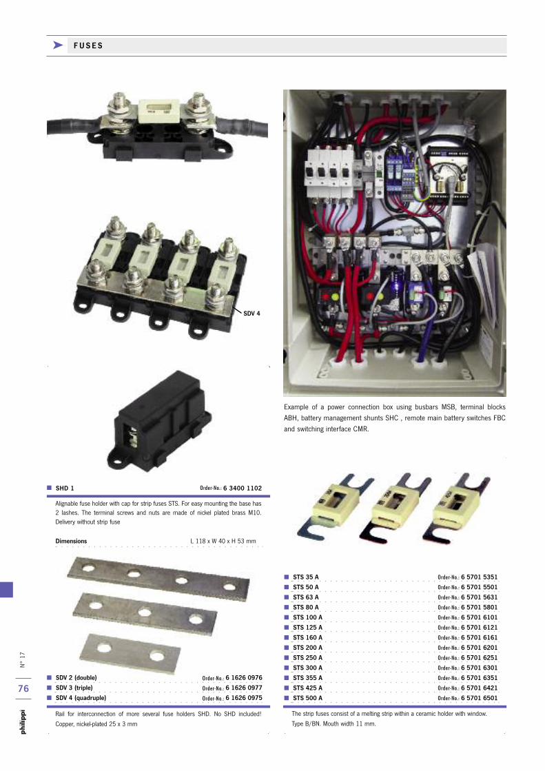
N° 17
76
SDV 4
STS 35 A Order-No.: 6 5701 5351
STS 50 A Order-No.: 6 5701 5501
STS 63 A Order-No.: 6 5701 5631
STS 80 A Order-No.: 6 5701 5801
STS 100 A Order-No.: 6 5701 6101
STS 125 A Order-No.: 6 5701 6121
STS 160 A Order-No.: 6 5701 6161
STS 200 A Order-No.: 6 5701 6201
STS 250 A Order-No.: 6 5701 6251
STS 300 A Order-No.: 6 5701 6301
STS 355 A Order-No.: 6 5701 6351
STS 425 A Order-No.: 6 5701 6421
STS 500 A Order-No.: 6 5701 6501
The strip fuses consist of a melting strip within a ceramic holder with window.
Type B/BN. Mouth width 11 mm.
Rail for interconnection of more several fuse holders SHD. No SHD included!
Copper, nickel-plated 25 x 3 mm
SDV 2 (double) Order-No.: 6 1626 0976
SDV 3 (triple) Order-No.: 6 1626 0977
SDV 4 (quadruple) Order-No.: 6 1626 0975
Alignable fuse holder with cap for strip fuses STS. For easy mounting the base has 2 lashes. The terminal screws and nuts are made of nickel plated brass M10. Delivery without strip fuse
Dimensions L 118 x W 40 x H 53 mm
SHD 1 Order-No.: 6 3400 1102
Example of a power connection box using busbars MSB, terminal blocksABH, battery management shunts SHC , remote main battery switches FBCand switching interface CMR.
k F U S E S
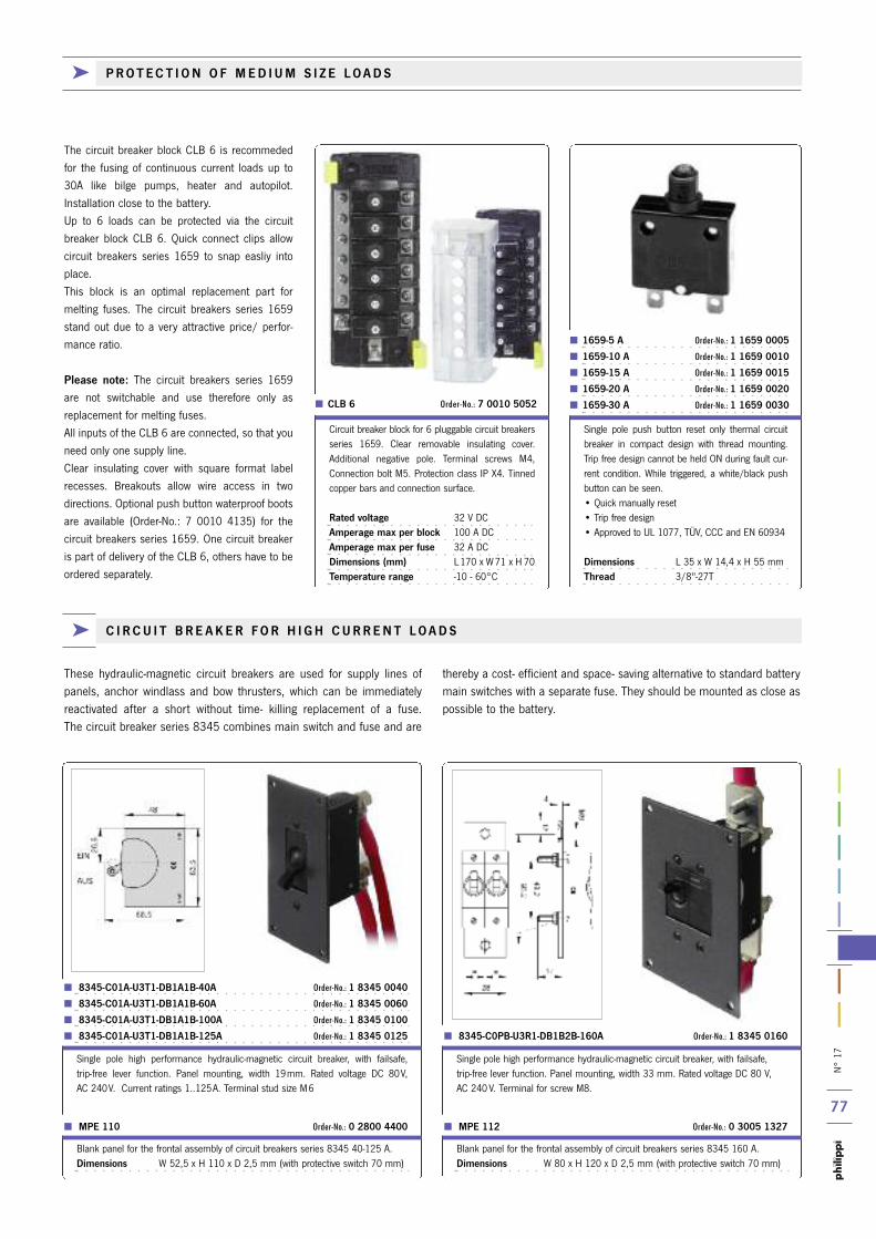
N° 17
77
k P R O T E C T I O N O F M E D I U M S I Z E L O A D S
These hydraulic-magnetic circuit breakers are used for supply lines ofpanels, anchor windlass and bow thrusters, which can be immediately reactivated after a short without time- killing replacement of a fuse. The circuit breaker series 8345 combines main switch and fuse and are
thereby a cost- efficient and space- saving alternative to standard batterymain switches with a separate fuse. They should be mounted as close as possible to the battery.
8345-C01A-U3T1-DB1A1B-40A Order-No.: 1 8345 0040
8345-C01A-U3T1-DB1A1B-60A Order-No.: 1 8345 0060
8345-C01A-U3T1-DB1A1B-100A Order-No.: 1 8345 0100
8345-C01A-U3T1-DB1A1B-125A Order-No.: 1 8345 0125
Single pole high performance hydraulic-magnetic circuit breaker, with failsafe, trip-free lever function. Panel mounting, width 19mm. Rated voltage DC 80V, AC 240V. Current ratings 1..125A. Terminal stud size M6
MPE 110 Order-No.: 0 2800 4400
Blank panel for the frontal assembly of circuit breakers series 8345 40-125 A.Dimensions W 52,5 x H 110 x D 2,5 mm (with protective switch 70 mm)
k C I R C U I T B R E A K E R F O R H I G H C U R R E N T L O A D S
The circuit breaker block CLB 6 is recommededfor the fusing of continuous current loads up to30A like bilge pumps, heater and autopilot.Installation close to the battery.Up to 6 loads can be protected via the circuitbreaker block CLB 6. Quick connect clips allowcircuit breakers series 1659 to snap easliy intoplace.This block is an optimal replacement part for melting fuses. The circuit breakers series 1659stand out due to a very attractive price/ perfor-mance ratio.
Please note: The circuit breakers series 1659are not switchable and use therefore only asreplacement for melting fuses. All inputs of the CLB 6 are connected, so that youneed only one supply line.Clear insulating cover with square format labelrecesses. Breakouts allow wire access in twodirections. Optional push button waterproof bootsare available (Order-No.: 7 0010 4135) for thecircuit breakers series 1659. One circuit breakeris part of delivery of the CLB 6, others have to beordered separately.
CLB 6 Order-No.: 7 0010 5052
1659-5 A Order-No.: 1 1659 0005
1659-10 A Order-No.: 1 1659 0010
1659-15 A Order-No.: 1 1659 0015
1659-20 A Order-No.: 1 1659 0020
1659-30 A Order-No.: 1 1659 0030
Circuit breaker block for 6 pluggable circuit breakersseries 1659. Clear removable insulating cover.Additional negative pole. Terminal screws M4,Connection bolt M5. Protection class IP X4. Tinnedcopper bars and connection surface.
Rated voltage 32 V DCAmperage max per block 100 A DCAmperage max per fuse 32 A DCDimensions (mm) L170 x W71 x H 70 Temperature range -10 - 60°C
Single pole push button reset only thermal circuitbreaker in compact design with thread mounting.Trip free design cannot be held ON during fault cur-rent condition. While triggered, a white/black pushbutton can be seen. • Quick manually reset• Trip free design• Approved to UL 1077, TÜV, CCC and EN 60934
Dimensions L 35 x W 14,4 x H 55 mmThread 3/8"-27T
8345-C0PB-U3R1-DB1B2B-160A Order-No.: 1 8345 0160
Single pole high performance hydraulic-magnetic circuit breaker, with failsafe, trip-free lever function. Panel mounting, width 33 mm. Rated voltage DC 80 V, AC 240 V. Terminal for screw M8.
MPE 112 Order-No.: 0 3005 1327
Blank panel for the frontal assembly of circuit breakers series 8345 160 A.Dimensions W 80 x H 120 x D 2,5 mm (with protective switch 70 mm)
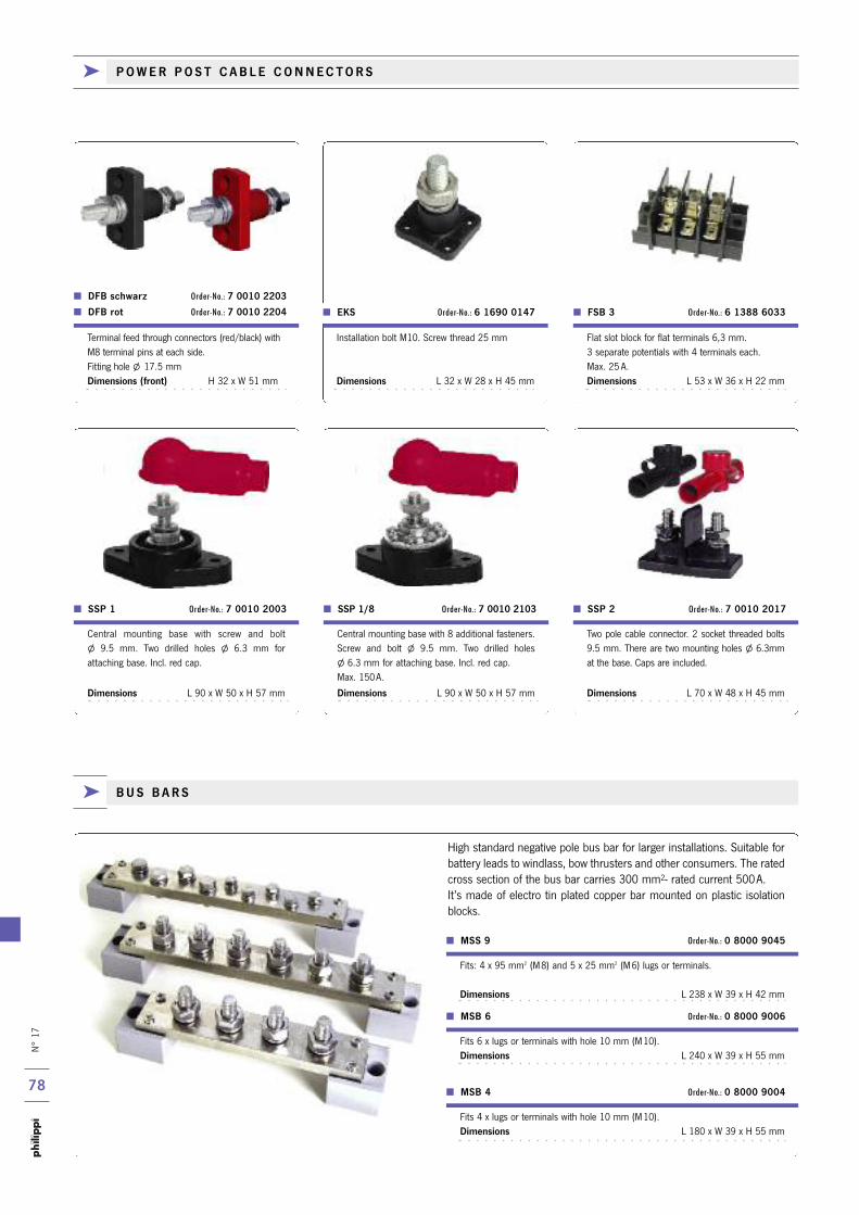
N° 17
78
Fits: 4 x 95 mm2 (M8) and 5 x 25 mm2 (M6) lugs or terminals.
Dimensions L 238 x W 39 x H 42 mm
MSS 9 Order-No.: 0 8000 9045
Fits 4 x lugs or terminals with hole 10 mm (M10). Dimensions L 180 x W 39 x H 55 mm
Fits 6 x lugs or terminals with hole 10 mm (M10). Dimensions L 240 x W 39 x H 55 mm
MSB 4 Order-No.: 0 8000 9004
MSB 6 Order-No.: 0 8000 9006
k P O W E R P O S T C A B L E C O N N E C T O R S
High standard negative pole bus bar for larger installations. Suitable forbattery leads to windlass, bow thrusters and other consumers. The ratedcross section of the bus bar carries 300 mm2- rated current 500A.It’s made of electro tin plated copper bar mounted on plastic isolationblocks.
Two pole cable connector. 2 socket threaded bolts9.5 mm. There are two mounting holes l 6.3mmat the base. Caps are included.
Dimensions L 70 x W 48 x H 45 mm
Central mounting base with 8 additional fasteners.Screw and bolt l 9.5 mm. Two drilled holes l 6.3 mm for attaching base. Incl. red cap.Max. 150A.
Dimensions L 90 x W 50 x H 57 mm
Central mounting base with screw and bolt l 9.5 mm. Two drilled holes l 6.3 mm for attaching base. Incl. red cap.
Dimensions L 90 x W 50 x H 57 mm
SSP 1/8 Order-No.: 7 0010 2103 SSP 1 Order-No.: 7 0010 2003 SSP 2 Order-No.: 7 0010 2017
DFB schwarz Order-No.: 7 0010 2203
DFB rot Order-No.: 7 0010 2204
Flat slot block for flat terminals 6,3 mm. 3 separate potentials with 4 terminals each.Max. 25 A.Dimensions L 53 x W 36 x H 22 mm
Installation bolt M10. Screw thread 25 mm
Dimensions L 32 x W 28 x H 45 mm
FSB 3 Order-No.: 6 1388 6033 EKS Order-No.: 6 1690 0147
Terminal feed through connectors (red/black) withM8 terminal pins at each side.Fitting hole l 17.5 mmDimensions (front) H 32 x W 51 mm
k B U S B A R S

N° 17
79
100A
100A
150A
150A
M20x1,5 Order-No.: 5 0009 1930 M25x1,5 Order-No.: 5 0009 1931
Compact double bus bar with 5 consumer (10-32 screws) and 2 cable - connections (1 / 4 "bolts). For lugs diameter 4 (6) mm²-Incl. removable transparent cover.
Dimensions L 124 x W 66 x H 39 mm
SMS 14 Order-No.: 7 0010 2722
SMS 22 Order-No.: 7 0010 2302
Cover AMS 22 Order-No.: 7 0010 2716
SMS 12 Order-No.: 7 0010 2301
Cover AMS 12 Order-No.: 7 0010 2715
Compact bus bar with 20 outlets and 2 lead connections. (1/4” thread bolts). Forlugs diameter 4 (6) mm². Ideal for connection the negative leads in small networkinstallations. Matching cover AMS 22 for plug-on to the screw bolts.Dimensions L 235 x W 32 x H 32 mm
Compact bus bar with 20 outlets and 2 lead connections. (1/4” thread bolts). Forlugs diameter 4 (6) mm². Ideal for connection the negative leads in small networkinstallations. Matching cover AMS 12 for plug-on to the screw bolts.
Dimensions L 155 x W 32 x H 32 mm
SMS 7 Order-No.: 7 0010 2304
Cover AMS 7 Order-No.: 7 0010 2713
Compact bus bar with 5 outlets and 2 lead connections (1/4” thread bolts). Forlugs diameter 4 (6) mm². Ideal for connection the negative leads in small networkinstallations. Matching cover AMS 7 for plug-on to the screw bolts.
Dimensions L 107 x W 22 x H 22 mm
AZK 25 Order-No.: 6 0780 2407 AZK 60 Order-No.: 6 0780 6407 AZK 100 Order-No.: 6 0781 0410
The junction boxes (AZK) reveal a new dynamic in technic and design. Themoulded technic in the model AZK 25 offers mounting comfort. Because themoulds leading diaphragm are injected, their membranes can be punctured asneeded. The leads are driven through the punctured opening leaving the boxitself water sealed. Model AZK 60 has plenty of room for connection, and has
an accessable segment fitting. The leads are easily placed under the segmentfitting for an organized fit. Junction boxes may be mounted if needed, close toone another on either of the four sides. The AZK 60 and larger, require grom-mets for all connecting leads. All junction boxes are made of impact and flameresistant polystyrene. Square dimensions. Protective system IP 65.
k W AT E R P R O O F J U N C T I O N B O X E S
Grey junction box, with 5 pole high-set terminal10 mm2 (4 x 4 / 4 x 6 / 4 x 10 mm2). IP 65 withIP 54 adaptors and blanking plugs M32, sealrange 13 - 23 mm
Dimensions L 140 x W 140 x H 79 mm
Matching cable screw gland: (M 20x1.5/25x1,5)
Issued for cables l 10- 18 mm
Grey junction box, with 5 pole high-set terminal -6mm2 (4 x 2.5 / 4 x 4 / 3 x 6 mm2). IP 65 withIP 54 adaptors and blanking plugs M25, sealrange 9 - 18.5 mm
Dimensions L 110 x W 110 x H 67 mm
Matching cable screw gland: (M 20x1.5/25x1.5)
Issued for cables l 3- 10 mm
Grey junction box with 5 poles screw terminalsof 2.5 mm2 (4 x 1.5 / 4 x 2.5 mm2), soft sea-ling entry membrane M20. IP 65, seal range 2 - 16 mm
Dimensions L 80 x W 80 x H 52 mm
Matching cable screw gland: (M20x1,5)
k B U S B A R S
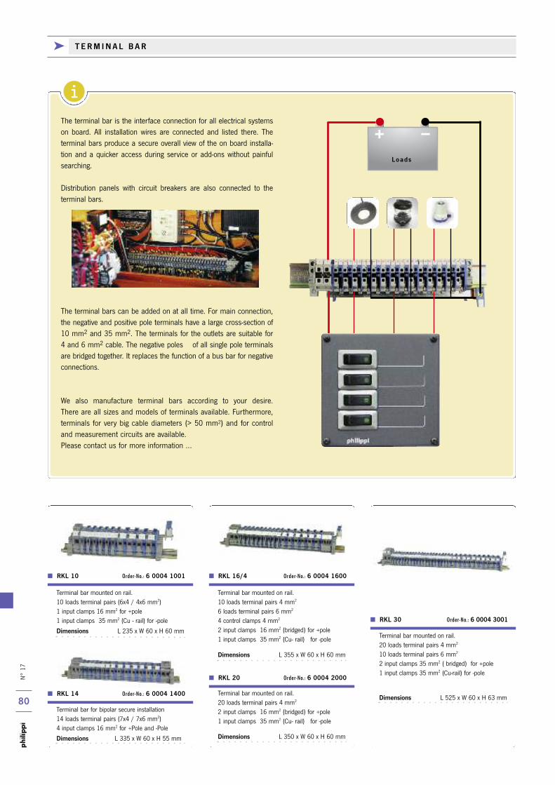
i
N° 17
80
k T E R M I N A L B A R
RKL 10 Order-No.: 6 0004 1001
RKL 14 Order-No.: 6 0004 1400
RKL 16/4 Order-No.: 6 0004 1600
RKL 30 Order-No.: 6 0004 3001
Terminal bar mounted on rail.20 loads terminal pairs 4 mm2
10 loads terminal pairs 6 mm2
2 input clamps 35 mm2 ( bridged) for +pole1 input clamps 35 mm2 (Cu-rail) for -pole
Dimensions L 525 x W 60 x H 63 mm
Terminal bar mounted on rail.10 loads terminal pairs 4 mm2
6 loads terminal pairs 6 mm2
4 control clamps 4 mm2
2 input clamps 16 mm2 (bridged) for +pole1 input clamps 35 mm2 (Cu- rail) for -pole
Dimensions L 355 x W 60 x H 60 mm
Terminal bar for bipolar secure installation 14 loads terminal pairs (7x4 / 7x6 mm2) 4 input clamps 16 mm2 for +Pole and -Pole
Dimensions L 335 x W 60 x H 55 mm
Terminal bar mounted on rail. 10 loads terminal pairs (6x4 / 4x6 mm2) 1 input clamps 16 mm2 for +pole 1 input clamps 35 mm2 (Cu - rail) for -pole
Dimensions L 235 x W 60 x H 60 mm
The terminal bar is the interface connection for all electrical systemson board. All installation wires are connected and listed there. The terminal bars produce a secure overall view of the on board installa-tion and a quicker access during service or add-ons without painful searching.
Distribution panels with circuit breakers are also connected to the terminal bars.
The terminal bars can be added on at all time. For main connection,the negative and positive pole terminals have a large cross-section of10 mm2 and 35 mm2. The terminals for the outlets are suitable for 4 and 6 mm2 cable. The negative poles of all single pole terminalsare bridged together. It replaces the function of a bus bar for negativeconnections.
We also manufacture terminal bars according to your desire. There are all sizes and models of terminals available. Furthermore,terminals for very big cable diameters (> 50 mm2) and for controland measurement circuits are available. Please contact us for more information ...
RKL 20 Order-No.: 6 0004 2000
Terminal bar mounted on rail.20 loads terminal pairs 4 mm2
2 input clamps 16 mm2 (bridged) for +pole1 input clamps 35 mm2 (Cu- rail) for -pole
Dimensions L 350 x W 60 x H 60 mm
Loads
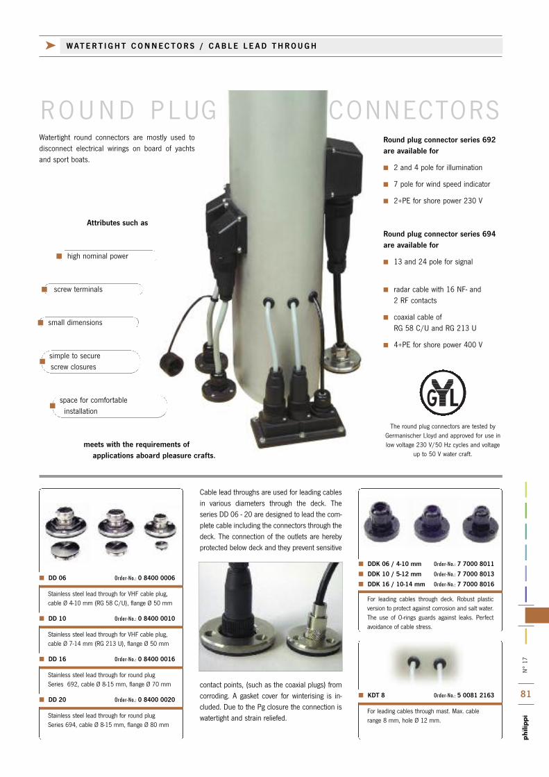
N°
17
81 KDT 8 Order-No.: 5 0081 2163
DDK 06 / 4-10 mm Order-No.: 7 7000 8011
DDK 10 / 5-12 mm Order-No.: 7 7000 8013
DDK 16 / 10-14 mm Order-No.: 7 7000 8016
DD 20 Order-No.: 0 8400 0020
DD 16 Order-No.: 0 8400 0016
DD 10 Order-No.: 0 8400 0010
DD 06 Order-No.: 0 8400 0006
k WATER T I GHT CONNECTORS / C AB L E L E AD THROUGH
The round plug connectors are tested byGermanischer Lloyd and approved for use inlow voltage 230 V/50 Hz cycles and voltage
up to 50 V water craft.
Attributes such as
high nominal power
screw terminals
small dimensions
simple to securescrew closures
space for comfortableinstallation
meets with the requirements of applications aboard pleasure crafts.
Round plug connector series 692are available for
2 and 4 pole for illumination
7 pole for wind speed indicator
2+PE for shore power 230 V
Round plug connector series 694are available for
13 and 24 pole for signal
radar cable with 16 NF- and 2 RF contacts
coaxial cable of RG 58 C/U and RG 213 U
4+PE for shore power 400 V
Watertight round connectors are mostly used todisconnect electrical wirings on board of yachtsand sport boats.
R OUND P LUG CONNECTORS
For leading cables through mast. Max. cablerange 8 mm, hole Ø 12 mm.
For leading cables through deck. Robust plastic version to protect against corrosion and salt water.The use of O-rings guards against leaks. Perfect avoidance of cable stress.
contact points, (such as the coaxial plugs) fromcorroding. A gasket cover for winterising is in-cluded. Due to the Pg closure the connection iswatertight and strain reliefed.Stainless steel lead through for round plug
Series 694, cable Ø 8-15 mm, flange Ø 80 mm
Stainless steel lead through for round plug Series 692, cable Ø 8-15 mm, flange Ø 70 mm
Stainless steel lead through for VHF cable plug, cable Ø 7-14 mm (RG 213 U), flange Ø 50 mm
Stainless steel lead through for VHF cable plug, cable Ø 4-10 mm (RG 58 C/U), flange Ø 50 mm
Cable lead throughs are used for leading cablesin various diameters through the deck. Theseries DD 06 - 20 are designed to lead the com-plete cable including the connectors through thedeck. The connection of the outlets are herebyprotected below deck and they prevent sensitive

N°
17
82
Pg closure with flange ring for assem-bly on a block or angular housing -Series 692. Suitable for leadingthrough a coaxial plug cable with max.22 mm diameter. A screw-on cap isincluded.
Flange Ring Pg 13,5Order-No.: 0 0569 0000
Protecting cap -No.: 0 0565 0000
Protective cap against contact on con-nection side of plug and socket
Block housing for deck fitting with 3flange plugs, sockets or Pg 13,5 closure for cable through deck
Dimensions L 117 x W 56 x T 25 mm
“568” Block housing 3Order-No.: 0 0568 0000
Square housing for vertical fitting ondeck. By use of this housing only thediameter of cable is drilled throughdeck.
Dimensions L 56 x W 53 x H 25 mm
“567” Square housing Order-No.: 0 0567 0000
90° angular housing for horizontal fit-ting of flange plug and socket on deck.
Dimensions L 56 x W 53 x H 36 mm
“566” Angular housingOrder-No.: 0 0566 0000
k ACCES SOR I E S FOR ROUND P LUG CONNECTORS - S E R I E S 6 9 2
No. of poles 2+PE 2 4 7 Protective cover
Max. cross sections 2,5 mm2 2,5 mm2 2,5 mm2 1,5 mm2
Type of connection screwed screwed screwed screwed
Cable bore 10-12 mm 6-8 mm 6-8 mm 6-8 mm
Contact surface Ag Ag Ag Ag
Type of protection IP 66 IP 66 IP 66 IP 66
Housing material PBT-gv PBT-gv PBT-gv PBT-gv PBT
Rated power per contact 16 A 16 A 16 A 10 A
Rated voltage according VDE 0110/72 230 V 50 V 50 V 50 V
Flame-proof according UL-94 self extinguishing non combustible non combustible non combustible non combustible
Coupling plug Order-No.: Order-No.: Order-No.: Order-No.: Order-No.:
4 0209 2904 4 4501 4402 4 0209 4404 4 0217 4007 4 2299 0000
Angle plug Order-No.: Order-No.: Order-No.: Order-No.:
– 4 4501 7402 4 0209 7004 4 0217 7007 4 2299 0000
Coupling socket Order-No.: Order-No.: Order-No.: Order-No.: Order-No.:
4 0210 2904 4 4502 4402 4 0210 4404 4 0218 4007 4 2300 0000
Flange plug Order-No.: Order-No.: Order-No.: Order-No.: Order-No.:
4 0211 3004 4 4503 0002 4 0211 0004 4 0219 0007 4 2301 0000
Flange socket Order-No.: Order-No.: Order-No.: Order-No.: Order-No.:
4 0212 3004 4 4504 0002 4 0212 0004 4 0220 0007 4 2302 0000
Series 692
k WATER T I GHT CONNECTORS
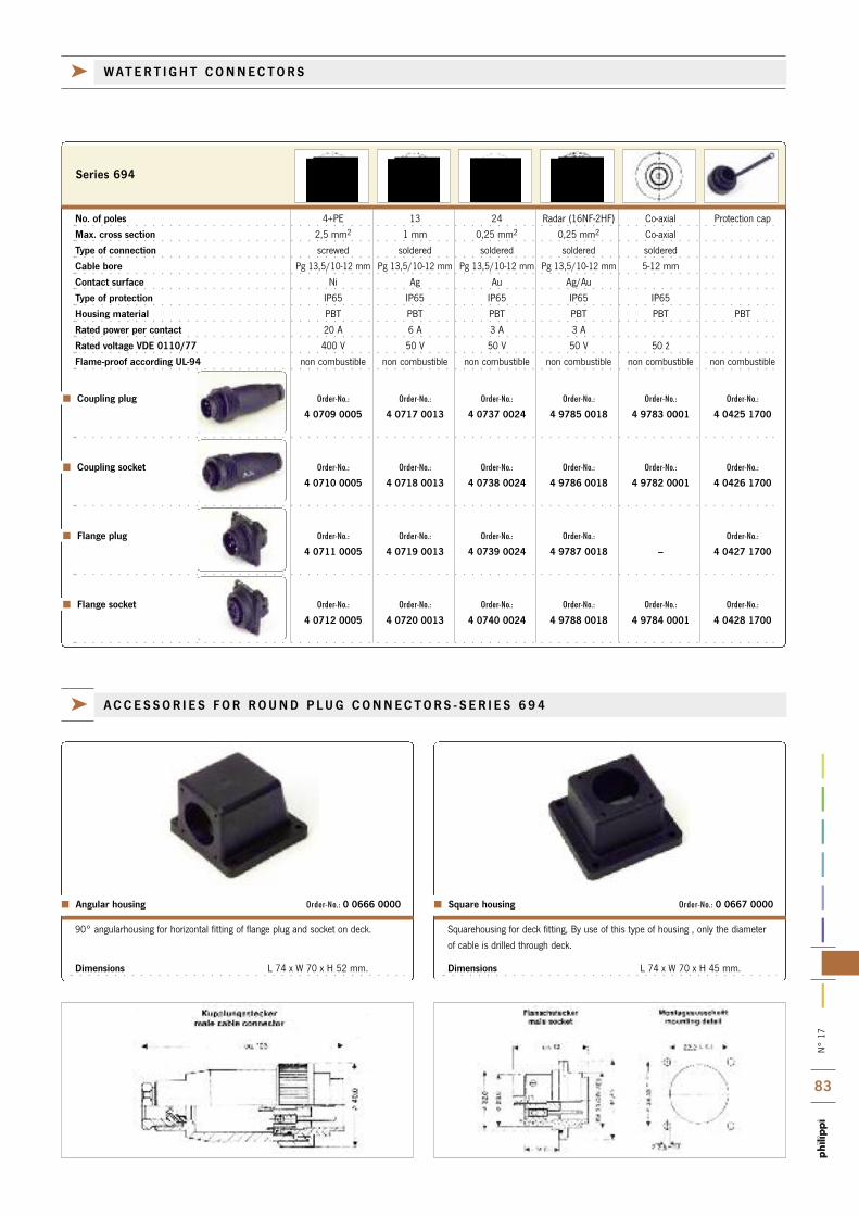
N°
17
83
Squarehousing for deck fitting, By use of this type of housing , only the diameter
of cable is drilled through deck.
Dimensions L 74 x W 70 x H 45 mm.
90° angularhousing for horizontal fitting of flange plug and socket on deck.
Dimensions L 74 x W 70 x H 52 mm.
Square housing Order-No.: 0 0667 0000 Angular housing Order-No.: 0 0666 0000
k ACCES SOR I E S FOR ROUND P LUG CONNECTORS - S E R I E S 6 9 4
No. of poles 4+PE 13 24 Radar (16NF-2HF) Co-axial Protection cap
Max. cross section 2,5 mm2 1 mm 0,25 mm2 0,25 mm2 Co-axial
Type of connection screwed soldered soldered soldered soldered
Cable bore Pg 13,5/10-12 mm Pg 13,5/10-12 mm Pg 13,5/10-12 mm Pg 13,5/10-12 mm 5-12 mm
Contact surface Ni Ag Au Ag/Au
Type of protection IP65 IP65 IP65 IP65 IP65
Housing material PBT PBT PBT PBT PBT PBT
Rated power per contact 20 A 6 A 3 A 3 A
Rated voltage VDE 0110/77 400 V 50 V 50 V 50 V 50 ž
Flame-proof according UL-94 non combustible non combustible non combustible non combustible non combustible non combustible
Coupling plug Order-No.: Order-No.: Order-No.: Order-No.: Order-No.: Order-No.:
4 0709 0005 4 0717 0013 4 0737 0024 4 9785 0018 4 9783 0001 4 0425 1700
Coupling socket Order-No.: Order-No.: Order-No.: Order-No.: Order-No.: Order-No.:
4 0710 0005 4 0718 0013 4 0738 0024 4 9786 0018 4 9782 0001 4 0426 1700
Flange plug Order-No.: Order-No.: Order-No.: Order-No.: Order-No.:
4 0711 0005 4 0719 0013 4 0739 0024 4 9787 0018 – 4 0427 1700
Flange socket Order-No.: Order-No.: Order-No.: Order-No.: Order-No.: Order-No.:
4 0712 0005 4 0720 0013 4 0740 0024 4 9788 0018 4 9784 0001 4 0428 1700
Series 694
k WATER T I GHT CONNECTORS

N°
17
84The contacts may be crimped or soldered. Assembly in the housing is without faste-
ners (snap-in). A hand grip is available as accessory. It can be fittedeither on the
plug or socket part. Connection diameter max. 25 mm2, protection type IP 23.
This is a plug connection in 2-pole version for special applications in thearea of higher current up to 80A / 96V made of heavy duty material.
Cap
Dimensions 38 x 53 x14 mm
Plug, terminal cross-section max. 2,5 mm2 , rated current 16 A
Dimensions Ø 37 x L 84 mm
Height 18 mm
MCS 12V Order-No.: 6 0011 1012
MCS 24V Order-No.: 6 0011 1024 MC CLIP Order-No.: 6 0011 9199
Socket
Dimensions Ø 37 mm
Fitting hole Ø 28 mm
Depth 22 mm
MCF 12V Order-No.: 6 0011 1112
MCF 24V Order-No.: 6 0011 1124
The newest technology in connectors is the MagCode system. A completelynew and revolutionary plug. Contacts are connected and hold together withthe power of magnetic force. As long as the plug and socket are not closed,the contacts are absent of power and prevent a short. Only after bringingboth contact groups together again the circuit will be closed. The MagCode connectors are available in voltage rates of 12 V and 24 V.
The small fitting depth allows a simple mounting in any problem space.Easy to fit is the cap for protection against moist and dirt. High operation safety in case of vibrations or in heavy seas, very important for mobile pho-nes or notebooks, which need an interruption-free power supply. An enco-der prevents connection between 12 V and 24 V.
LB 80 S Coupling plug incl. hand grip Order-No.: 6 1209 8000
LB 80 D Coupling socket Order-No.: 6 1210 8000
LB 80 H Grip only Order-No.: 6 1768 0000
Picture in original size
k H I GH DU T Y P LUG CONNECTORS FOR I N S I D E
Sub-miniature round plug connection with very small dimensions. 3 and 5
pole version. Usable for plug-in data processing in wind measurement, etc.
Housing polyamide (PA 66), bearing tube PBTB. Soldered connection. Gold
plate contacts. Max. cable clamp 4 - 6 mm. IP 67
Dimensions coupling plug, -socket L 57 x Ø 16 mm
Current in each contact (3 pole version) 7 A
Current in each contact (5 pole version) 5 A
Coupling plug Serie 720 - 3pol. Order-No.: 4 9105 0303 Coupling socket Serie 720 - 3pol. Order-No.: 4 9106 0303 Coupling plug Serie 720 - 5pol. Order-No.: 4 9113 0305 Coupling socket Serie 720 - 5pol. Order-No.: 4 9114 0305 Cap for coupling plug Order-No.: 4 2587 0000 Cap for coupling socket Order-No.: 4 2586 0000
k M IN I ATURE CONNECTORS FOR OU T S I D E U S E
k MAGNE T CONNECTORS FOR I N S I D E U S E
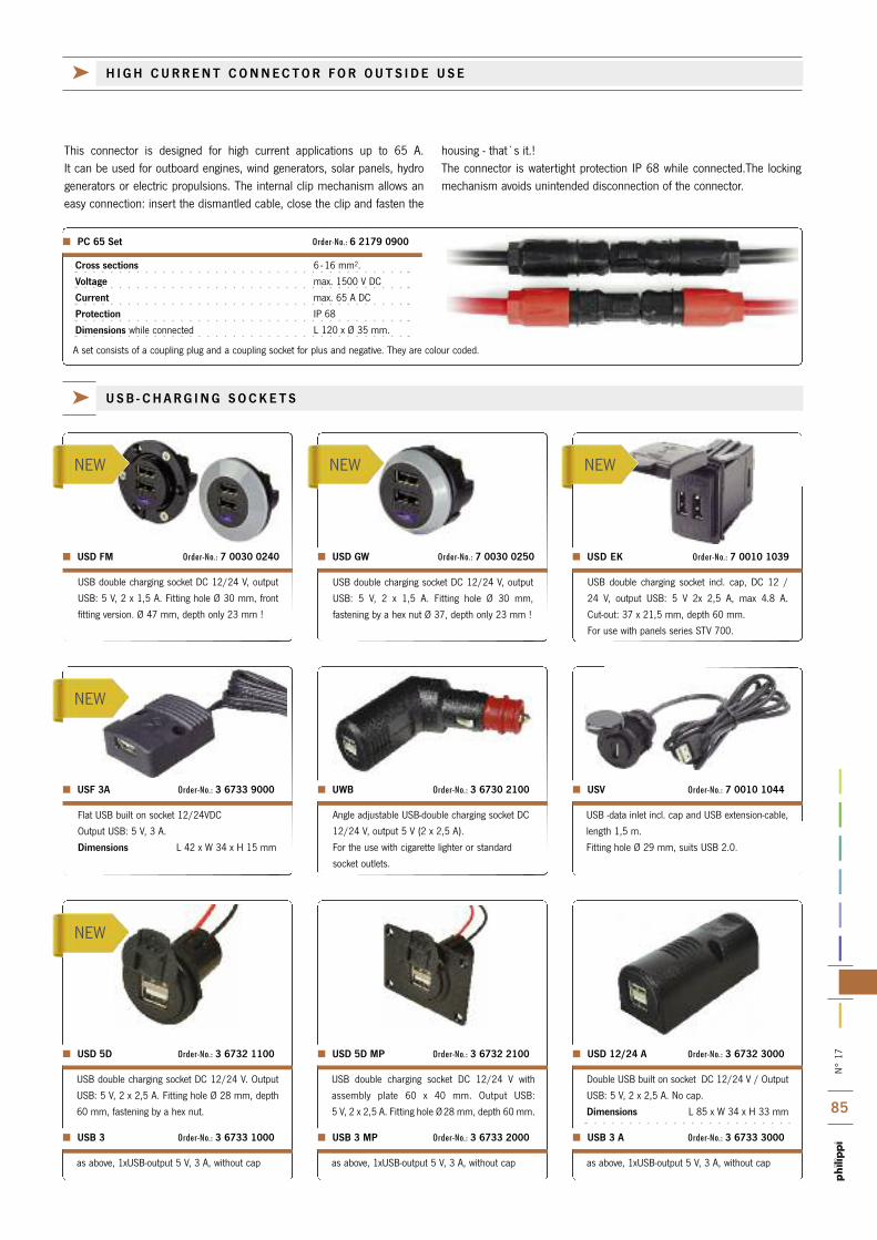
N°
17
85
NEW
NEW
NEW
NEW NEW
USB -data inlet incl. cap and USB extension-cable,
length 1,5 m.
Fitting hole Ø 29 mm, suits USB 2.0.
Angle adjustable USB-double charging socket DC
12/24 V, output 5 V (2 x 2,5 A).
For the use with cigarette lighter or standard
socket outlets.
UWB Order-No.: 3 6730 2100 USV Order-No.: 7 0010 1044
Flat USB built on socket 12/24VDC
Output USB: 5 V, 3 A.
Dimensions L 42 x W 34 x H 15 mm
USF 3A Order-No.: 3 6733 9000
USB double charging socket DC 12/24 V, output
USB: 5 V, 2 x 1,5 A. Fitting hole Ø 30 mm, front
fitting version. Ø 47 mm, depth only 23 mm !
USB double charging socket DC 12/24 V, output
USB: 5 V, 2 x 1,5 A. Fitting hole Ø 30 mm,
fastening by a hex nut Ø 37, depth only 23 mm !
USB double charging socket incl. cap, DC 12 /
24 V, output USB: 5 V 2x 2,5 A, max 4.8 A.
Cut-out: 37 x 21,5 mm, depth 60 mm.
For use with panels series STV 700.
USD FM Order-No.: 7 0030 0240 USD GW Order-No.: 7 0030 0250 USD EK Order-No.: 7 0010 1039
This connector is designed for high current applications up to 65 A. It can be used for outboard engines, wind generators, solar panels, hydrogenerators or electric propulsions. The internal clip mechanism allows aneasy connection: insert the dismantled cable, close the clip and fasten the
housing - that`s it.! The connector is watertight protection IP 68 while connected.The lockingmechanism avoids unintended disconnection of the connector.
k H I GH CURRENT CONNECTOR FOR OU T S I D E U S E
k USB - CHARG ING SOCKE T S
as above, 1xUSB-output 5 V, 3 A, without capas above, 1xUSB-output 5 V, 3 A, without cap
USB 3 A Order-No.: 3 6733 3000 USB 3 Order-No.: 3 6733 1000
as above, 1xUSB-output 5 V, 3 A, without cap
USB 3 MP Order-No.: 3 6733 2000
Double USB built on socket DC 12/24 V / Output
USB: 5 V, 2 x 2,5 A. No cap.
Dimensions L 85 x W 34 x H 33 mm
USB double charging socket DC 12/24 V. Output
USB: 5 V, 2 x 2,5 A. Fitting hole Ø 28 mm, depth
60 mm, fastening by a hex nut.
USD 12/24 A Order-No.: 3 6732 3000 USD 5D Order-No.: 3 6732 1100
USB double charging socket DC 12/24 V with
assembly plate 60 x 40 mm. Output USB:
5 V, 2 x 2,5 A. Fitting hole Ø28 mm, depth 60 mm.
USD 5D MP Order-No.: 3 6732 2100
Cross sections 6 - 16 mm2.
Voltage max. 1500 V DC
Current max. 65 A DC
Protection IP 68
Dimensions while connected L 120 x Ø 35 mm.
A set consists of a coupling plug and a coupling socket for plus and negative. They are colour coded.
PC 65 Set Order-No.: 6 2179 0900

N°
17
86
Coupling for cable extension of powersupply to electrical equiment, lightingand multi-contact connection. Suitablefor normed/standard and universalplugs. Rated voltage 6-24 V, current 16 A.
KP 12/24Order-No.: 3 5762 0000
Waterproof built-in socket with protecti-ve cap. Suitable for normed/standardand universal plugs. Drill diameter Ø 18 mm, panel thickness max. 13 mm, completed with cable length0,3 m.
WSD 12/24Order-No.: 3 5200 5000
Built-in socket with protective cap.Suitable for normed/standard and universal plugs. Connection via flat terminals 6.3mm. Rated voltage 6-24 V,current 16 A.
DSD 12/24Order-No.: 3 5761 2002
Built-in normed socket with protectivecap against dust and spray. Suitable fornormed/standard and universal plugs.Hole-Ø 18 mm. Connection via flat ter-minals 6.3mm. Rated voltage 6-24 V,current 16 A
ESD 12/24Order-No.: 3 5760 7002
Built-in normed socket with protectivecap and assembly plate. Suitable fornormed and universal plugs.Connection via flat terminals 6.3mm.Rated voltage 6-24 V, current 16 A.Dimensions W 60 x H 45 x D 40mm
ESD 12/24 MPOrder-No.: 0 8000 0401
Built-on socket with protective cap.Suitable for normed/standard and uni-versal plugs. Connection via flat termi-nals 6.3mm. Rated voltage 6-24 V, current 16 A.
ASD 12/24Order-No.: 3 5760 8002
Standard plug for all kinds of additionalequipment connection, matches to allnormed plug sockets.Rated voltage 6-24 V, current 15 A.
NS 12/24 -15Order-No.: 3 5300 5001
Universal angle plug with function con-trol light (LED) and integrated fuse. Thetightening collar with bayonet snap-inensures a tight closure.Rated voltage 6-24 V, current 7.5A.Up to max. 1,5 mm2 cable diameter.
UWS 12/24-8AOrder-No.: 3 5773 0000
k CONNECTORS DC 1 2 / 2 4 V
Angle adjustable universal plug withintegrated fuse 8 A. The red adaptorcan be firmly positioned by a bayonetcatch, fitted for cigarette lighter andstandard socket outlets. Rated voltage6-24 V,Up to max 1,5 mm2 cable diameter.
SWS 12/24-8AOrder-No.: 3 6774 2000
Universal plug with integrated fuse 8Awith screw connection and pull relief.The red adaptor can be firmly positio-ned by a bayonet catch. Matches tobuilt in socket 12 and 21 mm. 6-24 V.
SUS 12/24-8 AOrder-No.: 3 6771 2000
Universal plug with integrated LED and pull relief. The red adaptor can befirmly positioned by a bayonet catch.Matches to built in socket 12 and 21 mm
USL 12/24-8 AOrder-No.: 3 6771 1100
Universal plug with screw-on connec-tion, pull relief. The red adaptor can befirmly positioned by a bayonet catch.Suitable for cigarette lighter socketsand normal plug. 6-24 V.
US 12/24-8 AOrder-No.: 3 6771 1000
US 12/24-16 AOrder-No.: 3 6771 1010

N°
17
87
KPB 12/24Order-No.: 3 6787 4000
ZKPZ 12/24Order-No.: 3 6787 9000
VK 12/24Order-No.: 3 6781 4000
WVK 12/24Order-No.: 3 6781 8100
NSA 12/24Order-No.: 3 6787 2900
AK 12/24Order-No.: 3 6787 2000
ZKP 12/24Order-No.: 3 6765 2000
AZS 12V Order-No.: 7 0002 1212
AZS 24V Order-No.: 7 0002 1224
ESD 12V screwOrder-No.: 7 0002 1218
ESD 24V screwOrder-No.: 7 0002 1824
ESD 12V roundOrder-No.: 7 0002 1216
ESD 12 V squareOrder-No.: 7 0002 1206
PSD 12/24 MPOrder-No.: 3 6804 1000
PSD 12/24Order-No.: 3 5790 6100
AZD 12/24Order-No.: 3 6760 4000
DZD 12/24Order-No.: 3 6760 1000
Built-in socket with cover on mountingplate. Suitable for universal plugs.. Rated voltage 6 -24V, max. current rate20A, mounting hole 28 mm,Dimensions W 60 x H 45 x D 60mm
Built-in socket with cover -withoutmounting plate!
Adapter to connect normed plug andcoupling. Socket connector interior Ø21mm (cigarette lighter socket), with flatcable, length 0,25 m. 6-24 V, max. 8 A.
3 pole built-on socket for universalplugs 16 A/6-24 V. Connection via flatterminals 6.3 mm.Dimensions L 85 x W 99 x H 33mm
Extension cord 2 x 0,75 mm2, length1m, for temporary connection with cro-codile clips for the battery poles. Socketconnector interior Ø 21 mmRated voltage 6-24 V, current 8 A.
Twin socket connector for all cigarettelighter sockets. Socket connector interiorØ 21 mm.Integrated exchangable 10Afuse. Flat cable 2x 0,75mm2, 0,25 m.Rated voltage 6-24V, current. 2 x 5 A.
Extension cord with safety universalplug and exchangeable 8 A fuse. Flatcable length 4 m.Rated voltage 6-24 V, current 8 A.
Extension cord 2 x 0,75 mm2 with safe-ty universal plug has an integrated 8 Afuse. Socket connector interiorØ21 mm. Helix cable, length 0,6m to3,0 m. Rated voltage 6-24 V, max. 8 A.
Adapter to connect normed plug andcoupling. Socket connector interior Ø21 mm, 6-24 V, max. 8 A.
Twin socket connector with universalplug, two standard socket outlets toconnect two electric accessoires. TheTÜV certified safety universal plug hasan exchangeable 16 A fuse, with con-tacts to DIN ISO 4165.Rated voltage 6-24 V, current. 2 x 8 A.
Built-on socket for universal plug.16A/6-24VDimensions L 85 x W 34 x H 33mm
Built-in standard socket the size of acigarette plug (21 mm) with protectivecap. Single hole mounting Ø 30 mm,threaded length 13 mm. Connection viaflat terminals 6.3mm.Rated voltage 6 -24 V, current 16 A.Dimensions Ø 36 x D 48 mm
Built-in normed socket the size of acigarette plug (21 mm) with protectivecap, screwed in through its roundassembly plate, suitable for universalplugs. Connection via flat terminals 6.3mm. Rated voltage 6-24 V, current 16A.Dimensions Ø 46 x D 48 mm
k CONNECTORS DC 1 2 / 2 4 V
Built-in normed socket the size of acigarette plug (21 mm) with protectivecap. With rectangular assembly plate,suitable for universal plugs. Connectionvia flat terminals 6.3mm.Rated voltage 6-24 V, current 16 A.Dimensions L 57x W 33 x D 48mm
Built on socket for a maximum currentof 16 A. Suitable for plugs Ø 21 mm.Connection via flat terminals 6.3mm.Rated voltage 6-24 V.
Dimensions L 81x W 55 x D 41mm
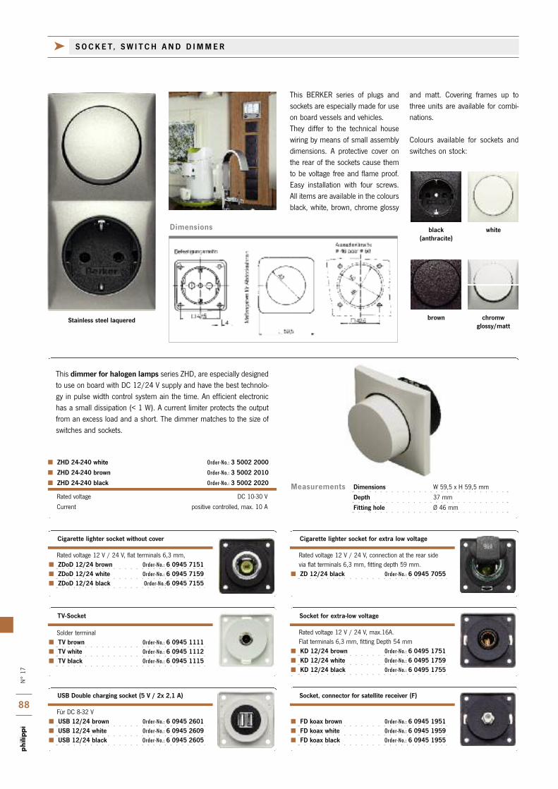
N°
17
88
Measurements
Für DC 8-32 V USB 12/24 brown Order-No.: 6 0945 2601 USB 12/24 white Order-No.: 6 0945 2609 USB 12/24 black Order-No.: 6 0945 2605
FD koax brown Order-No.: 6 0945 1951 FD koax white Order-No.: 6 0945 1959 FD koax black Order-No.: 6 0945 1955
Rated voltage 12 V / 24 V, flat terminals 6,3 mm, ZDoD 12/24 brown Order-No.: 6 0945 7151 ZDoD 12/24 white Order-No.: 6 0945 7159 ZDoD 12/24 black Order-No.:6 0945 7155
USB Double charging socket (5 V / 2x 2,1 A) Socket, connector for satellite receiver (F)
Cigarette lighter socket without cover
Solder terminal TV brown Order-No.: 6 0945 1111 TV white Order-No.: 6 0945 1112 TV black Order-No.: 6 0945 1115
TV-Socket
Rated voltage 12 V / 24 V, connection at the rear sidevia flat terminals 6,3 mm, fitting depth 59 mm.
ZD 12/24 black Order-No.: 6 0945 7055
Cigarette lighter socket for extra low voltage
Rated voltage 12 V / 24 V, max.16A.Flat terminals 6,3 mm, fitting Depth 54 mm
KD 12/24 brown Order-No.: 6 0495 1751 KD 12/24 white Order-No.: 6 0495 1759 KD 12/24 black Order-No.: 6 0495 1755
Socket for extra-low voltage
Dimensions W 59,5 x H 59,5 mm
Depth 37 mm
Fitting hole Ø 46 mm
Rated voltage DC 10-30 V
Current positive controlled, max. 10 A
ZHD 24-240 white Order-No.: 3 5002 2000
ZHD 24-240 brown Order-No.: 3 5002 2010
ZHD 24-240 black Order-No.: 3 5002 2020
This dimmer for halogen lamps series ZHD, are especially designedto use on board with DC 12/24 V supply and have the best technolo-gy in pulse width control system ain the time. An efficient electronichas a small dissipation (< 1 W). A current limiter protects the outputfrom an excess load and a short. The dimmer matches to the size ofswitches and sockets.
This BERKER series of plugs andsockets are especially made for useon board vessels and vehicles. They differ to the technical housewiring by means of small assemblydimensions. A protective cover onthe rear of the sockets cause themto be voltage free and flame proof.Easy installation with four screws.All items are available in the coloursblack, white, brown, chrome glossy
and matt. Covering frames up tothree units are available for combi-nations.
Colours available for sockets andswitches on stock:
Stainless steel laquered chromwglossy/matt
brown
whiteblack(anthracite)
k SOCKE T, SW I TCH AND D IMMER
Dimensions

N°
17
89
16 A/250 V, threaded terminal end, protective cover.Insert socket Ø 49 mm. Fitting depth 46 mm.
ND 230 F brown Order-No.: 6 0961 8551 ND 230 F white Order-No.: 6 0961 8582 ND 230 F black Order-No.: 6 0961 8555
Socket - French standard
ABG brown Order-No.: 6 0911 5151 ABG white Order-No.: 6 0911 5159 ABG black Order-No.: 6 0911 5155
16 A/250 V, threaded terminal end. Fitting depht 10 mm. ES 230 S brwon Order-No.: 6 0936 5551 ES 230 S white Order-No.: 6 0936 5559 ES 230 S black Order-No.: 6 0936 5555 ES 230 S chrome matt Order-No.: 6 0936 5528 ES 230 S chrome glossy Order-No.: 6 0936 5518 ES 230 S stainless steel Order-No.: 6 0936 5525
Double rocker switch
16 A/250 V, threaded terminal end. Fitting depht 10 mm. ET 230 S brown Order-No.: 6 0936 7551 ET 230 S white Order-No.: 6 0936 7559 ET 230 S black Order-No.: 6 0936 7555 ET 230 S chrome matt Order-No.: 6 0936 7528 ET 230 S chrome glossy Order-No.: 6 0936 7518 ET 230 S stainless steel Order-No.: 6 0936 7525
Double button N/O
Construction unit
Height 10 mm DZR brown Order-No.: 6 0918 2551 DZR white Order-No.: 6 0918 2552 DZR black Order-No.: 6 0918 2555
Distance ring
16 A/250 V, threaded terminal end. Fitting depht 10 mm. ES 230 T brown Order-No.: 6 0936 7151 ES 230 T white Order-No.: 6 0936 7159 ES 230 T black Order-No.: 6 0936 7155 ES 230 T chrome matt Order-No.: 6 0936 7128 ES 230 T chrome glossy Order-No.: 6 0936 7118 ES 230 T stainless steel Order-No.: 6 0936 7125
Button, N/O
16 A/250 V, threaded terminal end. Fitting depth 10 mm. ES 230 W brown Order-No.: 6 0936 5651 ES 230 W white Order-No.: 6 0936 5659 ES 230 W black Order-No.: 6 0936 5655 ES 230 W chrome matt Order-No.: 6 0936 5628 ES 230 W chrome glossy Order-No.: 6 0936 5618 ES 230 W stainless steel Order-No.: 6 0936 5625
Rocker switch - universal selective switch
For all sockets and switch types.Dimensions 59,5 x 178,5 mm
ADR 3 brown Order-No.: 6 0918 1951 ADR 3 white Order-No.: 6 0918 1959 ADR 3 black Order-No.: 6 0918 1955 ADR 3 chrome matt Order-No.: 6 0918 1928
Mounting panel for three items
10 A/250 V, threaded terminal end, protective cover.insert socket Ø 49 mm. Fitting depth 46 mm.
ND 230 CH brown Order-No.: 6 0962 5951 ND 230 CH white Order-No.: 6 0962 5952 ND 230 CH black Order-No.: 6 0962 5955
Socket - Swiss standard
Double mounting panel for all sockets and switch types Dimensions 59,5 x119 mm.
ADR 2 brown Order-No.: 6 0918 2651 ADR 2 white Order-No.: 6 0918 2659 ADR 2 black Order-No.: 6 0918 2655 ADR 2 chrome matt Order-No.: 6 0918 2628 ADR 2 chrome glossy Order-No.: 6 0918 2618 ADR 2 stainless steel Order-No.: 6 0918 2625
Double mounting panel
16 A/250 V, threaded terminal end, protective cover Insert socket Ø 46 mm. Fitting depth 36 mm
ND 230 brown Order-No.: 6 0941 8551 ND 230 white Order-No.: 6 0941 8552 ND 230 black Order-No.: 6 0941 8555
Socket - German standard
Single mounting panel for all sockets and switch types. Dimensions 59,5 x 59,5 mm
ADR 1 brown Order-No.: 6 0918 2751 ADR 1 white Order-No.: 6 0918 2759 ADR 1 black Order-No.: 6 0918 2755 ADR 1 chrome matt Order-No.: 6 0918 2728 ADR 1 chrome glossy Order-No.: 6 0918 2718 ADR 1 stainless steel Order-No.: 6 0918 2725
Single mounting panel
Mounting panel with hinged cover for all sockets types.Dimensioms 59,5 x 59,5 mm.
KLD brown Order-No.: 6 0918 2851 KLD white Order-No.: 6 0918 2859 KLD black Order-No.: 6 0918 2855 KLD chrome matt Order-No.: 6 0918 2828 KLD chrome glossy Order-No.: 6 0918 2818 KLD stainless steel Order-No.: 6 0918 2825
Mounting panel
k SOCKE T AND SW I TCH
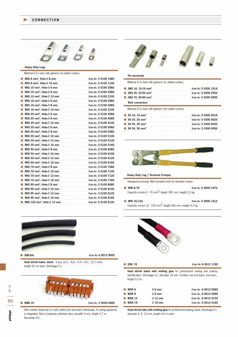
N°
17
90
WSR 6 Ø 6 mm Order-No.: 6 0012 0060
WSR 9 Ø 9 mm Order-No.: 6 0012 0090
WSR 12 Ø 12 mm Order-No.: 6 0012 0120
WSR 19 Ø 19 mm Order-No.: 6 0012 0190
SSB-Set Order-No: 6 0012 9005
Heat shrink tubes, black. 5 pcs. (3,2 / 4,8 / 6,4 / 9,5 / 12,7 mm) length 50 cm each. Shrinkage 2:1.
Wire marker dispenser to mark cables and terminals individually. A cutting applianceis integrated. Reel of polyester adhesive tape, breadth 5 mm, length 2,7 m.Numerals 0-9.
KMS 10 Order-No.: 5 0024 0009
Hexagonal pressing. With turnable tools for diameter choice.
WW 6/70 Order-No.: 5 0000 1070
Capacity crimps 6 - 70 mm2, length 390 mm, weight 2,3 kg.
WW 10/120 Order-No.: 5 0000 1012
Capacity crimps 10 - 120 mm2, length 660 mm, weight 4,3 kg.
Heavy Duty Lug / Terminal Crimper
Material E-Cu tube with galvanic tin plated surface.
RKS 6 mm2, Hole-Ø 8 mm Order-No.: 5 0100 1080
RKS 6 mm2, Hole-Ø 10 mm Order-No.: 5 0100 1100
RKS 10 mm2, Hole-Ø 6 mm Order-No.: 5 0100 2060
RKS 10 mm2, Hole-Ø 8 mm Order-No.: 5 0100 2080
RKS 10 mm2, Hole-Ø 10 mm Order-No.: 5 0100 2100
RKS 16 mm2, Hole-Ø 6 mm Order-No.: 5 0100 3060
RKS 16 mm2, Hole-Ø 8 mm Order-No.: 5 0100 3080
RKS 16 mm2, Hole-Ø 10 mm Order-No.: 5 0100 3100
RKS 25 mm2, Hole-Ø 6 mm Order-No.: 5 0100 4060
RKS 25 mm2, Hole-Ø 8 mm Order-No.: 5 0100 4080
RKS 25 mm2, Hole-Ø 10 mm Order-No.: 5 0100 4100
RKS 35 mm2, Hole-Ø 6 mm Order-No.: 5 0100 5060
RKS 35 mm2, Hole-Ø 8 mm Order-No.: 5 0100 5080
RKS 35 mm2, Hole-Ø 10 mm Order-No.: 5 0100 5100
RKS 35 mm2, Hole-Ø 12 mm Order-No.: 5 0100 5120
RKS 35 mm2, Hole-Ø 16 mm Order-No.: 5 0100 5160
RKS 50 mm2, Hole-Ø 8 mm Order-No.: 5 0100 6080
RKS 50 mm2, Hole-Ø 10 mm Order-No.: 5 0100 6100
RKS 50 mm2, Hole-Ø 12 mm Order-No.: 5 0100 6120
RKS 50 mm2, Hole-Ø 16 mm Order-No.: 5 0100 6160
RKS 70 mm2, Hole-Ø 8 mm Order-No.: 5 0100 7080
RKS 70 mm2, Hole-Ø 10 mm Order-No.: 5 0100 7100
RKS 70 mm2, Hole-Ø 12 mm Order-No.: 5 0100 7120
RKS 70 mm2, Hole-Ø 16 mm Order-No.: 5 0100 7160
RKS 95 mm2, Hole-Ø 8 mm Order-No.: 5 0100 8080
RKS 95 mm2, Hole-Ø 10 mm Order-No.: 5 0100 8100
RKS 95 mm2, Hole-Ø 12 mm Order-No.: 5 0100 8120
RKS 95 mm2, Hole-Ø 16 mm Order-No.: 5 0100 8160
RKS 120 mm2, Hole-Ø 12 mm Order-No.: 5 0100 9120
Material E-Cu tube with galvanic tin- plated surface.
SKS 16, 10-16 mm2 Order-No.: 5 0200 1016
SKS 35, 25-50 mm2 Order-No.: 5 0200 2550
SKS 70, 50-95 mm2 Order-No.: 5 0200 5095
Material E-Cu tube with galvanic tinn plated surface.
SV 16, 16 mm2 Order-No.: 5 0300 0016
SV 25, 25 mm2 Order-No.: 5 0300 0025
SV 35, 35 mm2 Order-No.: 5 0300 0035
SV 50, 50 mm2 Order-No.: 5 0300 0050
Butt connectors
Pin terminals
Heavy Duty Lugs
k CONNECT I ON
Heat shrink tubes with melting glue for professional sealing and polarity identification. Shrinkage 3:1, diameter 19 mm. Content: red and black, one each.,length 0,3 m.
SSK 19 Order-No: 6 0012 1190
Heat shrink tube with melting glue for professional sealing, black, Shrinkage 3:1,diameter 6, 9, 12 mm, length 0,6 m each.

i
N°
17
91
installation and maintenance of your boat electrical system.All lugs, terminals and spades are especially designed for the heavy harsh marine environment to accomplish all requirements. Pure tinned copper terminals, non-insulated or nylon-insulated give the best electrical contact.
Soldered connections of big cross sections are dangerous due tobad soldering joints. In that case the connection has a high resi-stance and danger of fire hazard. For professional result of lug andterminal crimps use only well matching tools. Our high quality toolsare designed to provide exact crimping and are easy to use in
UNI-Crimp WZ 42 Order-No.: 5 0000 0042
Crimp ratchet tool for isolated flat connectors, ratchet mechanism places a single crimp on insulated terminals in three cavities 0,5 - 6,0 mm2.
QKS 1,5-2,5 mm2, hole-Ø 4 mm Order-No.: 5 1630 0004 QKS 1,5-2,5 mm2, hole-Ø 5 mm Order-No.: 5 1630 0005 QKS 1,5-2,5 mm2, hole-Ø 6 mm Order-No.: 5 1630 0006
QKS 4-6 mm2, hole-Ø 4 mm Order-No.: 5 1650 0004 QKS 4-6 mm2, hole-Ø 5 mm Order-No.: 5 1650 0005 QKS 4-6 mm2, hole-Ø 6 mm Order-No.: 5 1650 0006
Ring Terminals. Package 10 pcs
FSI 6,3 mm / 0,5-1 mm2 rot Order-No.: 5 9163 0510
FSI 6,3 mm / 1,5-2,5 mm2 blau Order-No.: 5 9163 1525
FSI 6,3 mm / 4-6 mm2 gelb Order-No.: 5 9163 4060
HKL 3 Order-No.: 6 0022 1413
HKL 5 Order-No.: 6 0022 1415
Flat connectors isolated. Package 10 pcs
Lever clamp 3 / 5 fold for connetion of several wires. 32 A / 450 V, for all kind
of wires 0,25 - 4 mm
ITT 6,3 mm Order-No.: 5 9963 1525
Terminal boots, transparent, for flat connecors Package 10 pcs
AZH 6,3 mm / 1,5-2,5 mm2 Order-No.: 5 9263 1525
Multi stack connector, non isolated Package 10 pcs
FSH 6,3 mm / 1,5-2,5 mm2 Order-No.: 5 9063 1525 FSH 6,3 mm / 4-6 mm2 Order-No.: 5 9063 4060
Flat connectors non isolated. Package 10 pcs
Professional tool for pigtails. Cross sections 6 - 16 mm2.
EWZ 6-16 mm Order-No.: 5 0000 0561
Multible box with an assortment of five different pigtails, nylon-insulated. Revolving
cover for taking out the pigtails alternatively. Cross sections 0,75 - 6 mm2. Package
contains 430 pcs.
Professional tool for pigtails. Cross sections 0,5 - 4 mm2.
EWZ 0,5-4 mm Order-No.: 5 0000 0560
AEH BOX Order-No.: 5 9165 9000
k CONNECT I ON
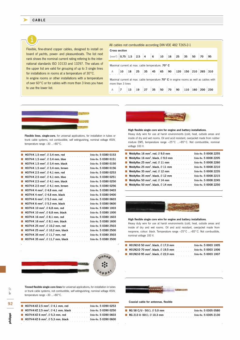
i
N°
17
92
c o p p e r
t inned
Cross section
(mm2) 0,75 1,5 2,5 4 6 10 16 25 35 50 70 95
Maximal current at max. cable temperature. 70° C
A 10 18 25 35 45 65 90 120 150 210 265 310
Maximal current at max. cable temperature 70° C in engine rooms as well as cables withmore than 3 lines
A 7 13 19 27 35 50 70 90 110 160 200 230
RG 58 C/U - 50W, Ø 5,0 mm Order-No.: 5 0305 0580
RG 213 U -50W, Ø 10,3 mm Order-No.: 5 0305 2130
Coaxial cable for antennas, flexible
Weldyflex 16 mm2, red, Ø 9,0 mm Order-No.: 5 0008 2255
Weldyflex 16 mm2, black, Ø 9,0 mm Order-No.: 5 0008 2205
Weldyflex 25 mm2, red, Ø 11 mm Order-No.: 5 0008 2260
Weldyflex 25 mm2, black, Ø 11 mm Order-No.: 5 0008 2210
Weldyflex 35 mm2, red, Ø 12 mm Order-No.: 5 0008 2235
Weldyflex 35 mm2, black, Ø 12 mm Order-No.: 5 0008 2215
Weldyflex 50 mm2, red, Ø 14 mm Order-No.: 5 0008 2245
Weldyflex 50 mm2, black, Ø 14 mm Order-No.: 5 0008 2250
H01N2-D 50 mm2, black, Ø 17,0 mm Order-No.: 5 0003 1005
H01N2-D 70 mm2, black, Ø 19,5 mm Order-No.: 5 0003 1006
H01N2-D 95 mm2, black, Ø 22,0 mm Order-No.: 5 0003 1007
High flexible single core wire for engine and battery installations.Heavy duty wire for use at harsh environments (cold, heat, outside areas and inside of dry and wet rooms. Oil and acid resistant, overjacket made from rubbermixture EM5, temperature range –25°C ...+85°C. Not combustible, nominal voltage 100 V.
High flexible single core wire for engine and battery installations.Heavy duty wire for use at harsh environments (cold, heat, outside areas and inside of dry and wet rooms. Oil and acid resistant, overjacket made from neoprene, colour: black. Temperature range –25°C ...+85°C. Not combustible,nominal voltage 100 V.
HO7V-K 1,5 mm2, Ø 3,4 mm, red Order-No.: 5 0380 0153
HO7V-K 1,5 mm2, Ø 3,4 mm, blue Order-No.: 5 0380 0151
HO7V-K 1,5 mm2, Ø 3,4 mm, black Order-No.: 5 0380 0150
HO7V-K 1,5 mm2, Ø 3,4 mm, brown Order-No.: 5 0380 0156
HO7V-K 2,5 mm2, Ø 4,1 mm, red Order-No.: 5 0380 0253
HO7V-K 2,5 mm2, Ø 4,1 mm, blue Order-No.: 5 0380 0251
HO7V-K 2,5 mm2, Ø 4,1 mm, black Order-No.: 5 0380 0250
HO7V-K 2,5 mm2, Ø 4,1 mm, brown Order-No.: 5 0380 0256
HO7V-K 4 mm2, Ø 4,8 mm, red Order-No.: 5 0380 0403
HO7V-K 4 mm2, Ø 4,8 mm, black Order-No.: 5 0380 0400
HO7V-K 6 mm2, Ø 5,3 mm, red Order-No.: 5 0380 0603
HO7V-K 6 mm2, Ø 5,3 mm, black Order-No.: 5 0380 0600
HO7V-K 10 mm2, Ø 6,8 mm, red Order-No.: 5 0380 1003
HO7V-K 10 mm2, Ø 6,8 mm, black Order-No.: 5 0380 1000
HO7V-K 16 mm2, Ø 8,1 mm, red Order-No.: 5 0380 1603
HO7V-K 16 mm2, Ø 8,1 mm, black Order-No.: 5 0380 1600
HO7V-K 25 mm2, Ø 10,2 mm, red Order-No.: 5 0380 2503
HO7V-K 25 mm2, Ø 10,2 mm, black Order-No.: 5 0380 2500
HO7V-K 35 mm2, Ø 11,7 mm, red Order-No.: 5 0380 3503
HO7V-K 35 mm2, Ø 11,7 mm, black Order-No.: 5 0380 3500
HO7V-K-VZ 2,5 mm2, Ø 4,1 mm, red Order-No.: 5 0390 0253
HO7V-K-VZ 2,5 mm2, Ø 4,1 mm, black Order-No.: 5 0390 0250
HO7V-K-VZ 6 mm2, Ø 5,3 mm, red Order-No.: 5 0390 0603
HO7V-K-VZ 6 mm2, Ø 5,3 mm, black Order-No.: 5 0390 0600
Flexible lines, single-core, for universal applications, for installation in tubes ortrunk cable systems, not combustible, self extinguishing, nominal voltage 450V,temperature range –30 ...+80°C.
Tinned flexible single core lines for universal applications, for installation in tubesor trunk cable systems, not combustible, self extinguishing, nominal voltage 450V,temperature range –30 ...+80°C.
Flexible, fine-strand copper cables, designed to install onboard of yachts, power- and pleasureboats. The list nextrank shows the nominal current rating refering to the inter-national standards ISO 10133 and 13297. The values ofthe upper list are valid for grouping of up to 3 single linesfor installations in rooms at a temperature of 30°C. In engine rooms or other installations with a temperatureof over 60°C or for cables with more than 3 lines you haveto use the lower list.
All cables not combustible according DIN VDE 482 T265-2-1
k CAB L E
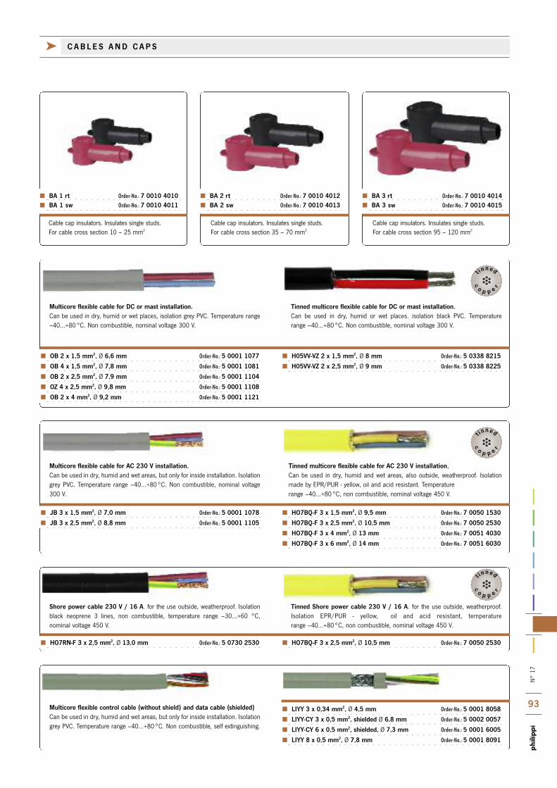
N°
17
93
c
o p p e r
t inned
c
o p p e r
t inned
c
o p p e r
t inned
k CAB L E S AND CAP S
Multicore flexible control cable (without shield) and data cable (shielded)Can be used in dry, humid and wet areas, but only for inside installation. Isolationgrey PVC. Temperature range –40...+80°C. Non combustible, self extinguishing.
LIYY 3 x 0,34 mm2, Ø 4,5 mm Order-No.: 5 0001 8058
LIYY-CY 3 x 0,5 mm2, shielded Ø 6,8 mm Order-No.: 5 0002 0057
LIYY-CY 6 x 0,5 mm2, shielded, Ø 7,3 mm Order-No.: 5 0001 6005
LIYY 8 x 0,5 mm2, Ø 7,8 mm Order-No.: 5 0001 8091
HO7RN-F 3 x 2,5 mm2, Ø 13,0 mm Order-No.: 5 0730 2530 HO7BQ-F 3 x 2,5 mm2, Ø 10,5 mm Order-No.: 7 0050 2530
Shore power cable 230 V / 16 A. for the use outside, weatherproof. Isolationblack neoprene 3 lines, non combustible, temperature range –30...+60 °C, nominal voltage 450 V.
Tinned Shore power cable 230 V / 16 A. for the use outside, weatherproof.Isolation EPR/PUR - yellow, oil and acid resistant, temperature range –40...+80°C, non combustible, nominal voltage 450 V.
OB 2 x 1,5 mm2, Ø 6,6 mm Order-No.: 5 0001 1077
OB 4 x 1,5 mm2, Ø 7,8 mm Order-No.: 5 0001 1081
OB 2 x 2,5 mm2, Ø 7,9 mm Order-No.: 5 0001 1104
OZ 4 x 2,5 mm2, Ø 9,8 mm Order-No.: 5 0001 1108
OB 2 x 4 mm2, Ø 9,2 mm Order-No.: 5 0001 1121
H05VV-VZ 2 x 1,5 mm2, Ø 8 mm Order-No.: 5 0338 8215
H05VV-VZ 2 x 2,5 mm2, Ø 9 mm Order-No.: 5 0338 8225
JB 3 x 1,5 mm2, Ø 7,0 mm Order-No.: 5 0001 1078
JB 3 x 2,5 mm2, Ø 8,8 mm Order-No.: 5 0001 1105
HO7BQ-F 3 x 1,5 mm2, Ø 9,5 mm Order-No.: 7 0050 1530
HO7BQ-F 3 x 2,5 mm2, Ø 10,5 mm Order-No.: 7 0050 2530
HO7BQ-F 3 x 4 mm2, Ø 13 mm Order-No.: 7 0051 4030
HO7BQ-F 3 x 6 mm2, Ø 14 mm Order-No.: 7 0051 6030
Multicore flexible cable for DC or mast installation.Can be used in dry, humid or wet places, isolation grey PVC. Temperature range–40...+80°C. Non combustible, nominal voltage 300 V.
Tinned multicore flexible cable for DC or mast installation.Can be used in dry, humid or wet places. isolation black PVC. Temperature range –40...+80°C. Non combustible, nominal voltage 300 V.
Multicore flexible cable for AC 230 V installation.Can be used in dry, humid and wet areas, but only for inside installation. Isolationgrey PVC. Temperature range –40...+80°C. Non combustible, nominal voltage300 V.
Tinned multicore flexible cable for AC 230 V installation.Can be used in dry, humid and wet areas, also outside, weatherproof. Isolationmade by EPR/PUR - yellow, oil and acid resistant. Temperature range –40...+80°C, non combustible, nominal voltage 450 V.
Cable cap insulators. Insulates single studs. For cable cross section 10 – 25 mm2
Cable cap insulators. Insulates single studs. For cable cross section 35 – 70 mm2
Cable cap insulators. Insulates single studs. For cable cross section 95 – 120 mm2
BA 1 rt Order-No.: 7 0010 4010 BA 1 sw Order-No.: 7 0010 4011
BA 2 rt Order-No.: 7 0010 4012 BA 2 sw Order-No.: 7 0010 4013
BA 3 rt Order-No.: 7 0010 4014 BA 3 sw Order-No.: 7 0010 4015

N°
17
94
NEW
NEW
NEW
NEW
NEW
NEW
NEW
NEW
NEW
Waterproof wall light for inside and outside use.
Very small and efficient, completely encapsulated
electronic. Destinated for the illumination of
shelfs, stowage rooms or for outside illumination.
Light outlet at the side,
DC 8 - 30 V, 5 W, luminous colour 4000 K.
Luminous colour 2700 K on demand.
Dimensions: L 100 x W 50 x H 6 mm
Super flat surface light with power LED,
Housing aluminium style with acrylic glass,
Ø 75 mm, height 10 mm.
Push button for: ON / OFF / Dimming
DC 8 - 30 V, 3 W, luminous colour 2700 K.
Super flat surface light with power LED,
Housing chrome with acrylic glass, Ø 75 mm,
height 10 mm.
Push button for: ON / OFF / Dimming
DC 8 - 30 V, 3 W, luminous colour 2700 K.
Waterproof wall light for inside and outside use.
Very small and efficient, completely encapsulated
electronic. Destinated for the illumination of
shelfs, stowage rooms or for outside illumination.
Light outlet at the side,
DC 8 - 30 V, 1,2 W, luminous colour 4000 K.
Luminous colour 2700 K on demand.
Dimensions: L 60 x W 20 x H 6 mm
Cupboard 7 shelf light with integrated push
button. DC 8 - 30 V, 1 W, 4000 K,
Dimensions L 44 x W 14 x H 7.5 mm
Super flat surface light with power LED,
Square housing 90 x 90 mm, depth 10 mm.
DC 8 - 30 V, 3 W, luminous colour 2700 K
Built on light, 50 power-LEDs produce a constant
and shadowfree illumination.
Push button for: ON / OFF / Dimming
DC 8 - 30 V, 7 W, luminous colour 2700 K.
Dimensions: L 280 x W 20 x H 10 mm.
Spot light 2,5 W with a flexible arm 20 or 30 cm,
Push button at the base for: ON / OFF / Dimming,
Cable outlet underneath the base, Angle of light
22°,
DC 8 - 30 V, 2.5 W, luminous colour 2700 K
The very small flexible spot is designed as an
optimal reading light. The length of the flexible
neck is 20 cm with a diameter of 4 mm, the base-
Ø is 26 mm. The head of the light is very small:
only 7x7x65 mm! Push button at the base: ON /
OFF / 3 step dimming.
DC 8 - 30 V, 1.5 W, luminous colour 4000 K.
LED WL5 Order-No.: 3 9000 5450
LED LRT Alu Order-No.: 3 9000 5254 LED LRT Chrom Order-No.: 3 9000 5256
LED WL1,2 Order-No.: 3 9000 5457 LED SLT Order-No.: 3 9000 5723
LED LQT Order-No.: 3 9000 5674
LED LLT 30 Order-No.: 3 9000 5498 LED MFT Order-No.: 3 9000 5441
LED LBF 20 Order-No.: 3 9000 0968
LED LBF 30 Order-No.: 3 9000 0969
k L ED L I GHT S
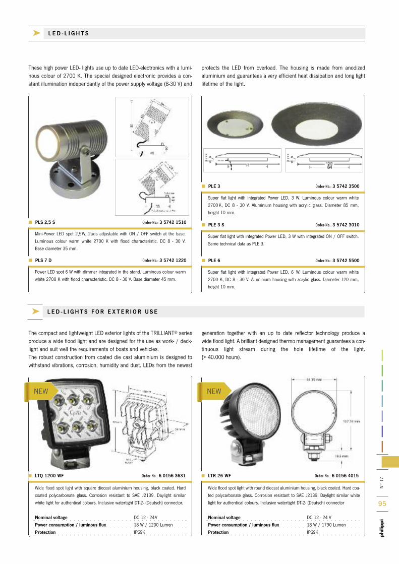
N°
17
95
NEW NEW
k L ED - L I GHT S FOR E X T ER I OR U S E
The compact and lightweight LED exterior lights of the TRILLIANT® seriesproduce a wide flood light and are designed for the use as work- / deck-light and suit well the requirements of boats and vehicles. The robust construction from coated die cast aluminium is designed towithstand vibrations, corrosion, humidity and dust. LEDs from the newest
generation together with an up to date reflector technology produce a wide flood light. A brilliant designed thermo management guarantees a con-tinuous light stream during the hole lifetime of the light. (> 40.000 hours).
Wide flood spot light with square diecast aluminium housing, black coated. Hard
coated polycarbonate glass. Corrosion resistant to SAE J2139. Daylight similar
white light for authentical colours. Inclusive watertight DT-2- (Deutsch) connector.
Nominal voltage DC 12 - 24V
Power consumption / luminous flux 18 W / 1200 Lumen
Protection IP69K
> LTQ 1200 WF Order-No.: 6 0156 3631
Wide flood spot light with round diecast aluminium housing, black coated. Hard coa-
ted polycarbonate glass. Corrosion resistant to SAE J2139. Daylight similar white
light for authentical colours. Inclusive watertight DT-2- (Deutsch) connector
Nominal voltage DC 12 - 24 V
Power consumption / luminous flux 18 W / 1790 Lumen
Protection IP69K
> LTR 26 WF Order-No.: 6 0156 4015
Super flat light with integrated Power LED, 3 W. Luminous colour warm white
2700 K, DC 8 - 30 V. Aluminium housing with acrylic glass. Diameter 85 mm,
height 10 mm.
Mini-Power LED spot 2,5W, 2axis adjustable with ON / OFF switch at the base.
Luminous colour warm white 2700 K with flood characteristic. DC 8 - 30 V.
Base diameter 35 mm.
PLE 3 Order-No.: 3 5742 3500
PLS 2,5 S Order-No.: 3 5742 1510
Super flat light with integrated Power LED, 3 W with integrated ON / OFF switch.
Same technical data as PLE 3.
PLE 3 S Order-No.: 3 5742 3010
Super flat light with integrated Power LED, 6 W. Luminous colour warm white
2700 K, DC 8 - 30 V. Aluminium housing with acrylic glass. Diameter 120 mm,
height 10 mm.
Power LED spot 6 W with dimmer integrated in the stand. Luminous colour warm
white 2700 K with flood characteristic. DC 8 - 30 V. Base diameter 45 mm.
PLE 6 Order-No.: 3 5742 5500 PLS 7 D Order-No.: 3 5742 1220
These high power LED- lights use up to date LED-electronics with a lumi-nous colour of 2700 K. The special designed electronic provides a con-stant illumination independantly of the power supply voltage (8-30 V) and
protects the LED from overload. The housing is made from anodized aluminium and guarantees a very efficient heat dissipation and long lightlifetime of the light.
k L ED - L I GHT S

N°
17
96
PLE A S E A SK FOR THE L AT E S T CATA LOG : I N FO@PH I L I PP I - ON L I N E . D E
WAL L -MOUNTED
CHAR T TAB L E
SUR FACE -MOUNTED
RECES S ED
E X TER I OR
k L ED - L I GHT S
L ED - D ES I GN L I GHTS
k TERMS OF SALE AND DEL IVERY
1.
Offers are without obligation. Right of prior sale and delivery is reserved. We are also reserve the right to amend the design of equipment as well as the utilisation of components with similar technical specifications.
2.
All individual prices are ex-warehouse at Remseck am Neckar or another external warehouse exclucive of packaging. Invoices are based on current actual prices except when otherwise agreed.
3.
Delivery is on the basis of cash on delivery.
4.
Invoices are payable within 30 days net. Interest may be added to out standing payments at the current bank interest rate. We reserve the right to charge costs related to low volume orders or a handling fee thereon.
5.
Deliveries are made at the risk and cost of the customer also when freigth costs are paid by the manufcturer. The costs of packaging at net value will be invoiced to the customer, not, however, returns.
6.
Goods must be checked upon receipt with regard to correctness, completeness, as well as freight damage. In the case of damage the customer must advise the Post Office, transport company, railway, or forwarding agent. Complaints of every natur may be recognised by the manufacturer only within 8 days of receipt of goods.
7.
Warranty is limited to the correct function of the equipment in accordance with the operating instuctions of the manufacturer when the damage is not caused by reason of improper assembly, installation, or incorrect operation. The duration of warranty is 24 months after installation, but expires at the latest 30 months after date of purchase. Warranty includes factory repairs and labour as well as replace-ment of defective components. For repair the equipment must be despatched by pre-paid post to us or one of our affiliated dealers. Costs related to to disassembly and re-installation are the responsibilitiy of the customer. The manu facturer will not be responsible for any consequential loss through contingency claims, penalties for non-performance of contracts, damages or loss arising out of improper operation insofar as they are not attributable to the manufacturerís deliberate or grossly negligent actions.
8.
The goods remain the property of the manufacturer until payment for them has been
completed. In the case of invoiced sales we are entitled to immendiately reclaim our
property when payment is delayed or substantive disimprovement in the financial status
of the customer occurs. Re-possession of the goods does not invalidate the contract
insofar as this is not otherwise stated.
9.
The place of contract is D - 71686 Remseck am Neckar.
The rele vant court jurisdiction district is Ludwigsburg.

kphilippi elektrische systeme gmbh | Neckaraue 19 | D-71686 Remseck am Neckar
Phone +49 7146 / 8744-0 | Fax +49 7146 / 8744-22 | E-Mail [email protected] | www.philippi-online.de
Copyright by philippi elektrische systeme gmbh
Des
ign:
Hild
wei
n Ko
mm
unik
atio
nsde
sign
, Lu
dwig
sbur
g |
Prin
ting:
Sch
wei
kert
, O
bers
ulm
-Esc
hena
u
MA
RIN
E P
OW
ER
SU
PP
LY
SY
ST
EM
S