marine power plants lectures
TRANSCRIPT

Marine Power Plants LecturesDr: Aly Hassan Elbatran
2
Requirements for marine power plants
1. To be approved by classification societies
2. Have as minimum as possible volume and weight
3. Have low fuel consumption
4. Easy maintenance and repair
5. Have to work at heavy duty levels for long periods
3
Selection of marine power plants
1. Good reliability
2. Good maintainability
3. Weight and volume
4. Type of fuel and fuel consumption
5. Cost
6. Vibration and noise
7. Level of experience for personnel
4
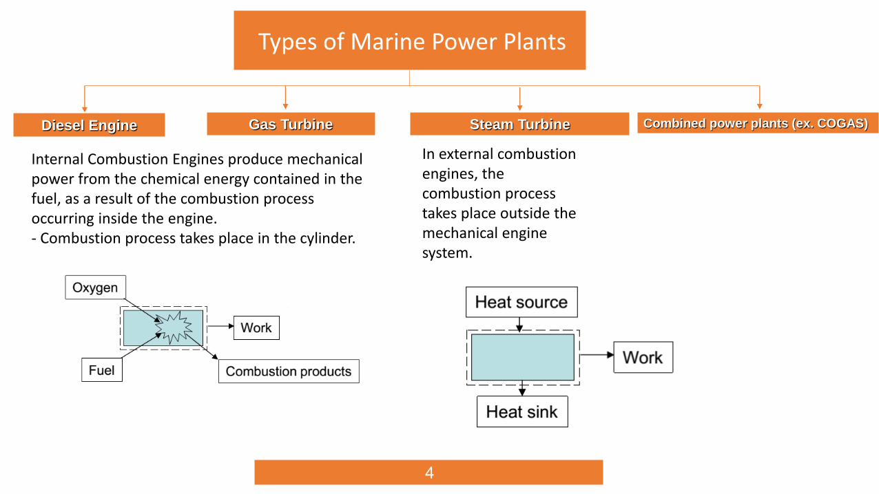
Types of Marine Power Plants
Diesel Engine Gas Turbine
Internal Combustion Engines produce mechanical power from the chemical energy contained in the fuel, as a result of the combustion process occurring inside the engine.- Combustion process takes place in the cylinder.
In external combustion engines, the combustion process takes place outside the mechanical engine system.
Combined power plants (ex. COGAS)Steam Turbine
5
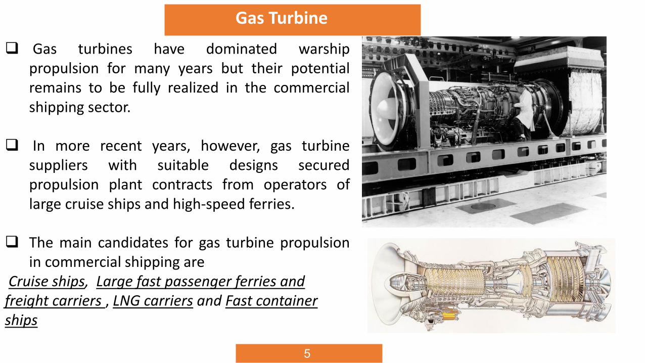
Gas Turbine
Gas turbines have dominated warshippropulsion for many years but their potentialremains to be fully realized in the commercialshipping sector.
In more recent years, however, gas turbinesuppliers with suitable designs securedpropulsion plant contracts from operators oflarge cruise ships and high-speed ferries.
The main candidates for gas turbine propulsionin commercial shipping are
Cruise ships, Large fast passenger ferries and freight carriers , LNG carriers and Fast container ships

6
Advantages of Gas Turbine1. High power-to-weight and power-to-volume ratios; aero-derived gas turbines typically exhibit power-to-weight
ratios at least four times those of medium-speed diesel engines; compactness and weight saving releases
machinery space for extra revenue-earning activities; a General Electric LM2500 aero-derived gas turbine unit
delivering 25 000 kW, for example, measures 4.75 m long, 1.6 m diameter and weighs 3.5 tonnes.
2. Low noise and vibration.
3. Ease of installation and servicing fostered by modular packages integrated with support systems and controls.
4. Modest maintenance costs, low spare part requirements and ease of replacement.
5. Reduced manning levels facilitated by full automation and unmanned machinery space capability.
6. Operational flexibility: swift start-up: no warm-up or idling period required; pick up load very rapidly, at a rate
of about 1 MW per second, idle can typically be reached within 30 s, ; followed by acceleration to full power;
deceleration can be equally as rapid, after which the turbine can be immediately shut down; subsequent restarts,
even after high power shutdown, can be instant with no ‘cool down’ restriction.
7. High availability, underwritten by excellent reliability and rapid repair and/or turbine change options.
7
Advantages of Gas Turbine (cont.)
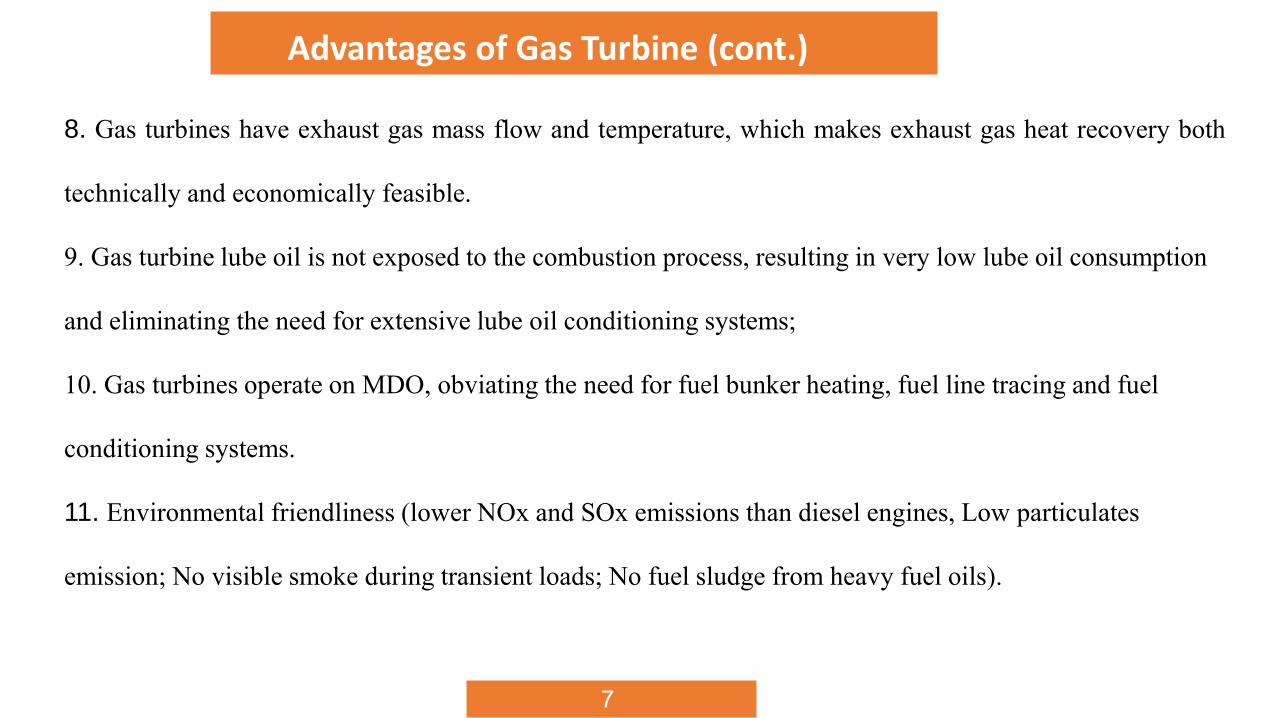
8. Gas turbines have exhaust gas mass flow and temperature, which makes exhaust gas heat recovery both
technically and economically feasible.
9. Gas turbine lube oil is not exposed to the combustion process, resulting in very low lube oil consumption
and eliminating the need for extensive lube oil conditioning systems;
10. Gas turbines operate on MDO, obviating the need for fuel bunker heating, fuel line tracing and fuel
conditioning systems.
11. Environmental friendliness (lower NOx and SOx emissions than diesel engines, Low particulates
emission; No visible smoke during transient loads; No fuel sludge from heavy fuel oils).
8
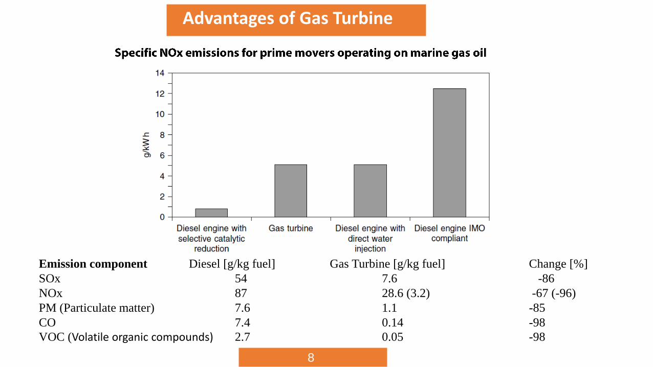
Advantages of Gas Turbine
Emission component Diesel [g/kg fuel] Gas Turbine [g/kg fuel] Change [%]
SOx 54 7.6 -86
NOx 87 28.6 (3.2) -67 (-96)
PM (Particulate matter) 7.6 1.1 -85
CO 7.4 0.14 -98
VOC (Volatile organic compounds) 2.7 0.05 -98
8
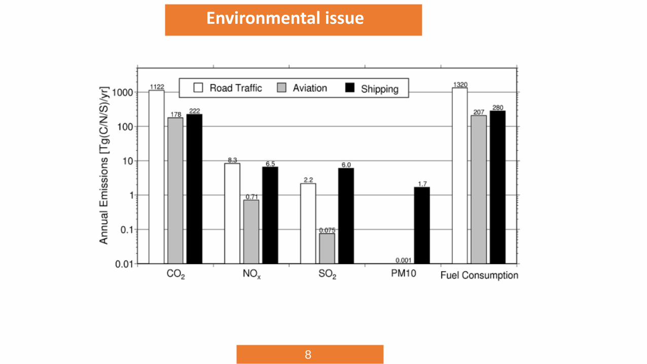
Environmental issue
10
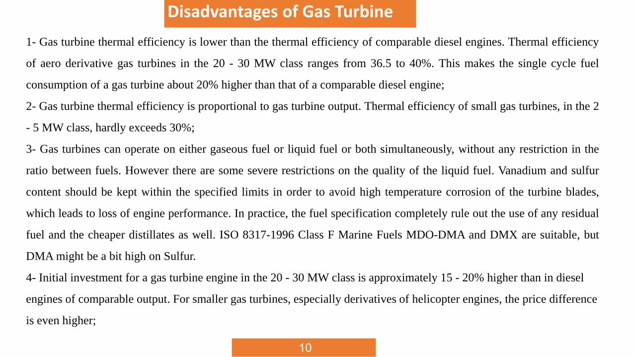
Disadvantages of Gas Turbine
1- Gas turbine thermal efficiency is lower than the thermal efficiency of comparable diesel engines. Thermal efficiency
of aero derivative gas turbines in the 20 - 30 MW class ranges from 36.5 to 40%. This makes the single cycle fuel
consumption of a gas turbine about 20% higher than that of a comparable diesel engine;
2- Gas turbine thermal efficiency is proportional to gas turbine output. Thermal efficiency of small gas turbines, in the 2
- 5 MW class, hardly exceeds 30%;
3- Gas turbines can operate on either gaseous fuel or liquid fuel or both simultaneously, without any restriction in the
ratio between fuels. However there are some severe restrictions on the quality of the liquid fuel. Vanadium and sulfur
content should be kept within the specified limits in order to avoid high temperature corrosion of the turbine blades,
which leads to loss of engine performance. In practice, the fuel specification completely rule out the use of any residual
fuel and the cheaper distillates as well. ISO 8317-1996 Class F Marine Fuels MDO-DMA and DMX are suitable, but
DMA might be a bit high on Sulfur.
4- Initial investment for a gas turbine engine in the 20 - 30 MW class is approximately 15 - 20% higher than in diesel
engines of comparable output. For smaller gas turbines, especially derivatives of helicopter engines, the price difference
is even higher;
11
Gas Turbine Myths and Misunderstandings
In the marine community there are still a lot of myths and misunderstandings about gas turbines.
Myth: Gas turbines have very low torque and cannot be used in mechanical drive applications.
Fact: Gas turbines can develop a very high torque, because the gas generator is aero-dynamically coupled to the
free power turbine. This allows the gas generator to spin up even when the free power turbine is stationary because
moment of inertia of the propeller. When the gas generator develops sufficient air flow, the torque of the free power
turbines overcomes the inertia of propeller.
Myth: Gas turbines are unable to take instant load application.
Fact:
The design of the gas turbine, with the gas generator aero-dynamically coupled to the free power turbine, lends itself
very well to instant application of heavy loads, which occur when a generator suddenly trips off-line. The speed of
the free power turbine might drop momentarily, but the gas generator will generate sufficient airflow to correct free
power turbine speed almost instantly.
12
Gas Turbine Myths and Misunderstandings
Myth:
Gas turbines only run on jet fuel.
Fact:
Gas turbines are perfectly happy to run on any liquid fuel available, as long as the combustion properties are all right.
Technically it is possible to burn well separated residual fuels. However, commonly available residual fuels have high
contents of Sulfur, Vanadium and alkali metals. The marine liquid fuel specifications of the gas turbine manufacturers
have been compiled to ensure satisfactory hot section replacement intervals. Distillate fuels, such as MDO DMX and
DMA (ISO-8217:1996(E), Category ISO-F) are acceptable, provided the Sulfur content is below 1.0%. Higher Sulfur and
alkali metals content will reduce hot section lifetime accordingly. Vanadium content is given as 0.5 ppm maximum to
reach a satisfactory lifetime. Higher Vanadium content will accelerate high temperature corrosion of the turbine
blades. The replacement cost of a prematurely worn hot section will definitely offset the gains of using non-compliant
fuels.
8
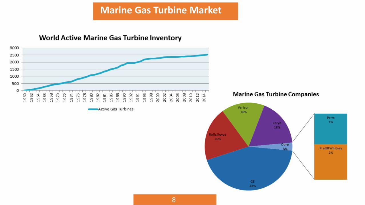
Marine Gas Turbine Market
14
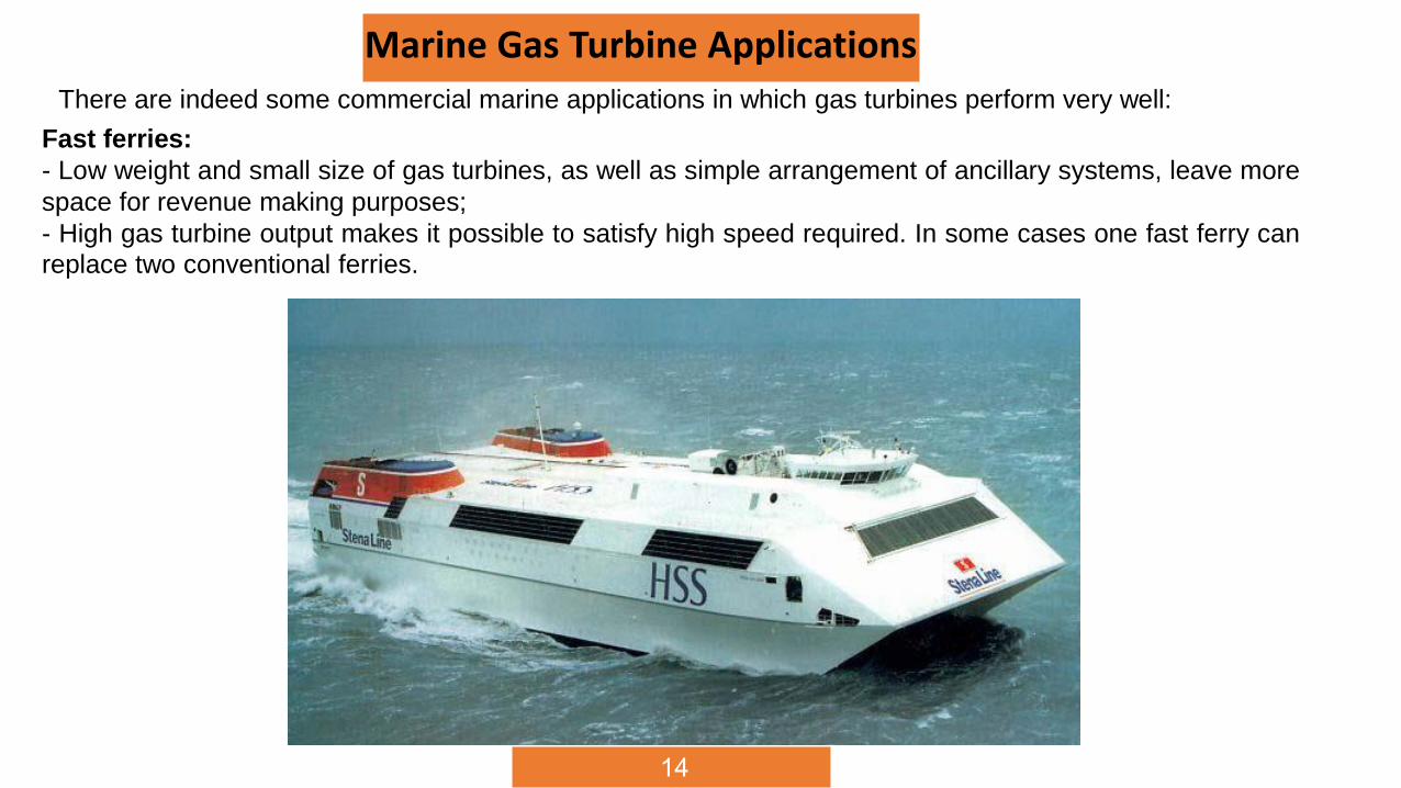
Marine Gas Turbine ApplicationsThere are indeed some commercial marine applications in which gas turbines perform very well:
Fast ferries:
- Low weight and small size of gas turbines, as well as simple arrangement of ancillary systems, leave more
space for revenue making purposes;
- High gas turbine output makes it possible to satisfy high speed required. In some cases one fast ferry can
replace two conventional ferries.
15
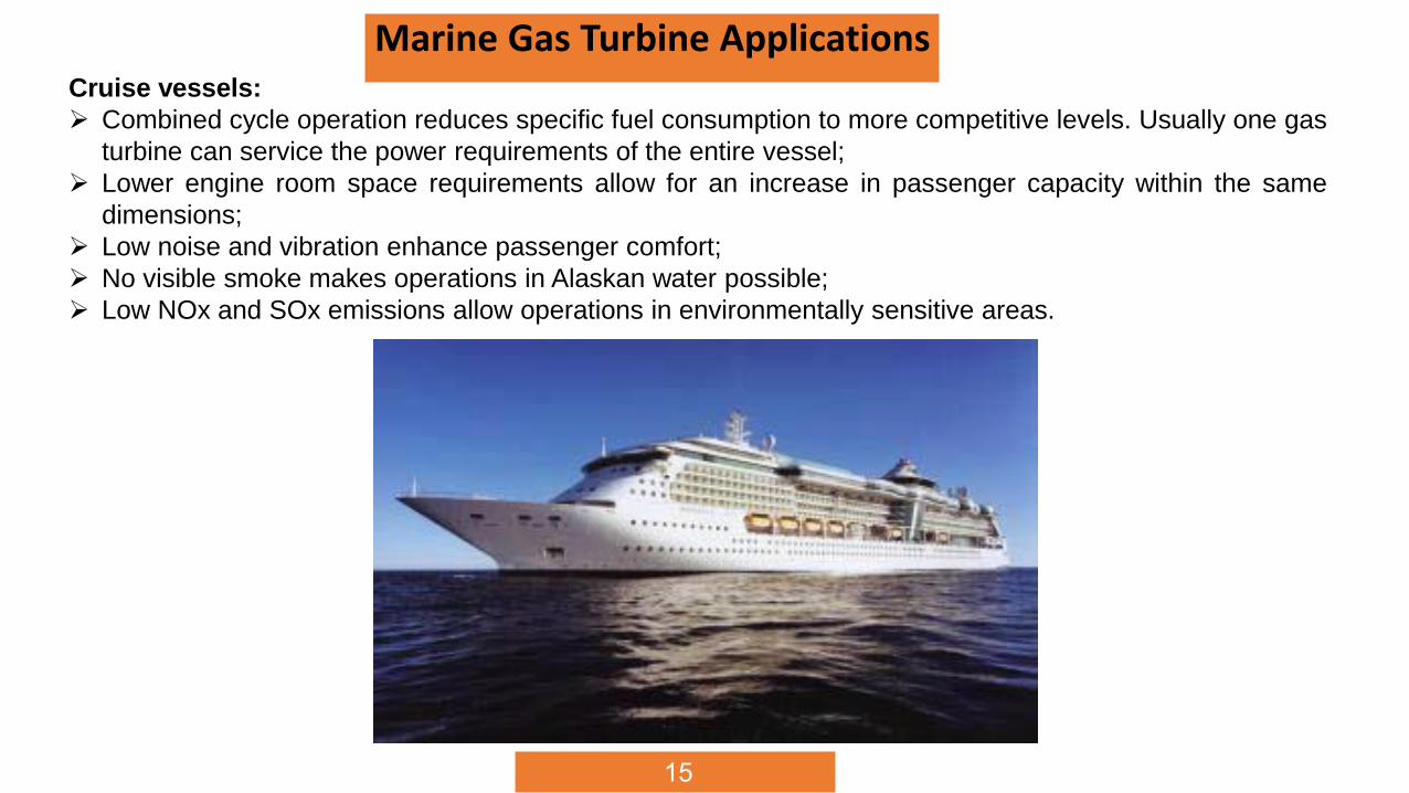
Marine Gas Turbine ApplicationsCruise vessels:
Combined cycle operation reduces specific fuel consumption to more competitive levels. Usually one gas
turbine can service the power requirements of the entire vessel;
Lower engine room space requirements allow for an increase in passenger capacity within the same
dimensions;
Low noise and vibration enhance passenger comfort;
No visible smoke makes operations in Alaskan water possible;
Low NOx and SOx emissions allow operations in environmentally sensitive areas.
16
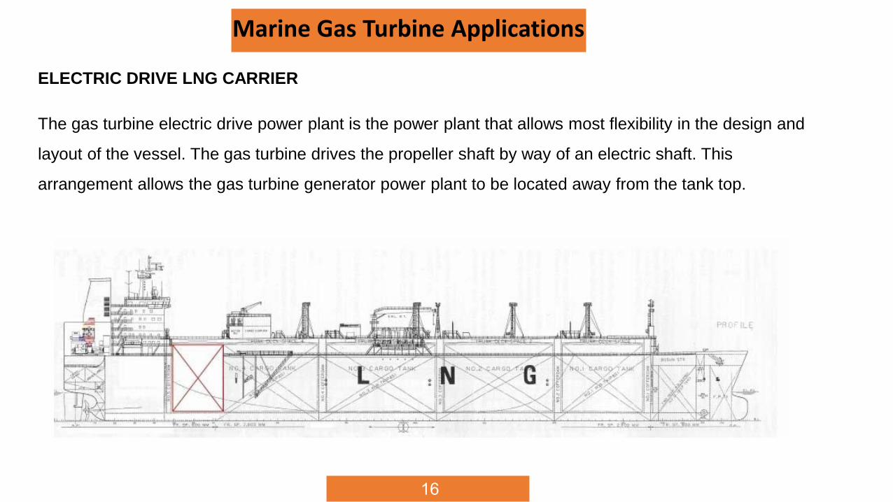
Marine Gas Turbine Applications
The gas turbine electric drive power plant is the power plant that allows most flexibility in the design and
layout of the vessel. The gas turbine drives the propeller shaft by way of an electric shaft. This
arrangement allows the gas turbine generator power plant to be located away from the tank top.
ELECTRIC DRIVE LNG CARRIER
17
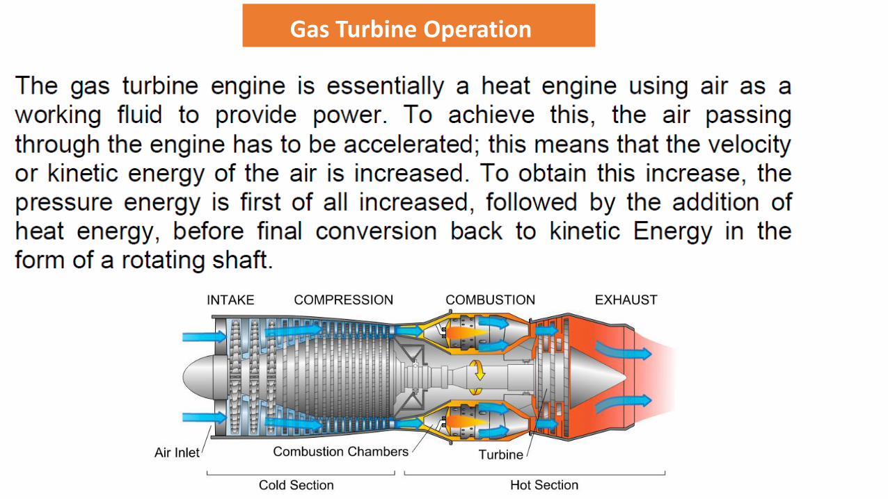
Gas Turbine Operation
18
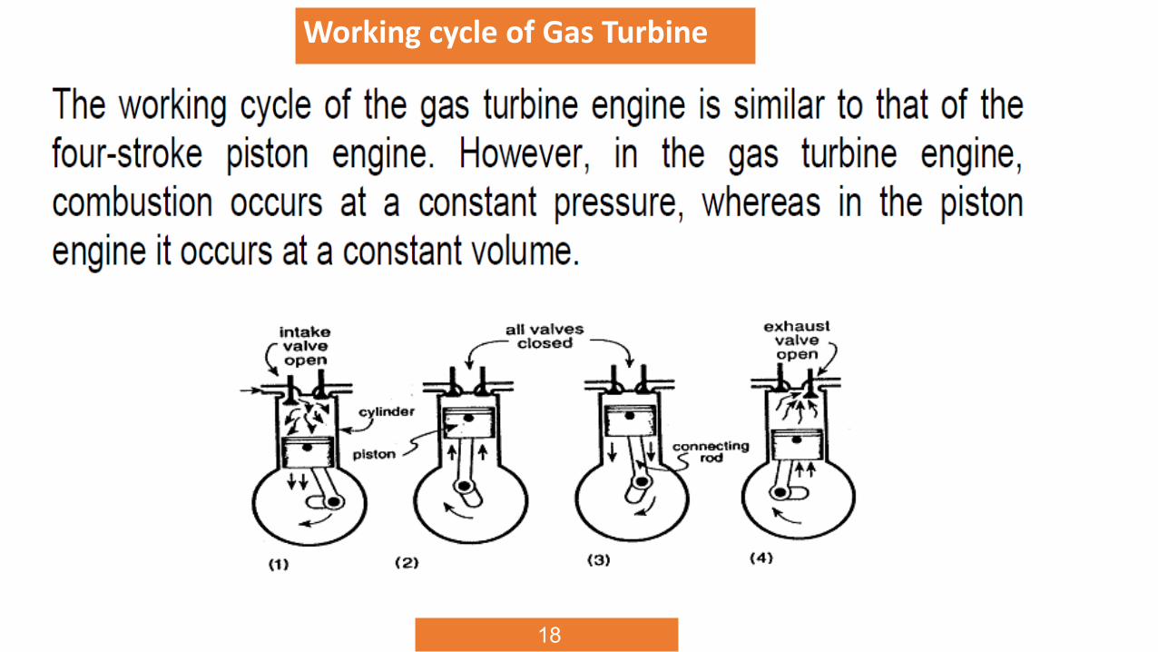
Working cycle of Gas Turbine
19
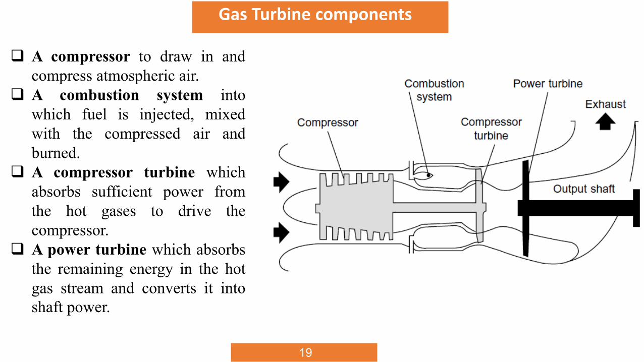
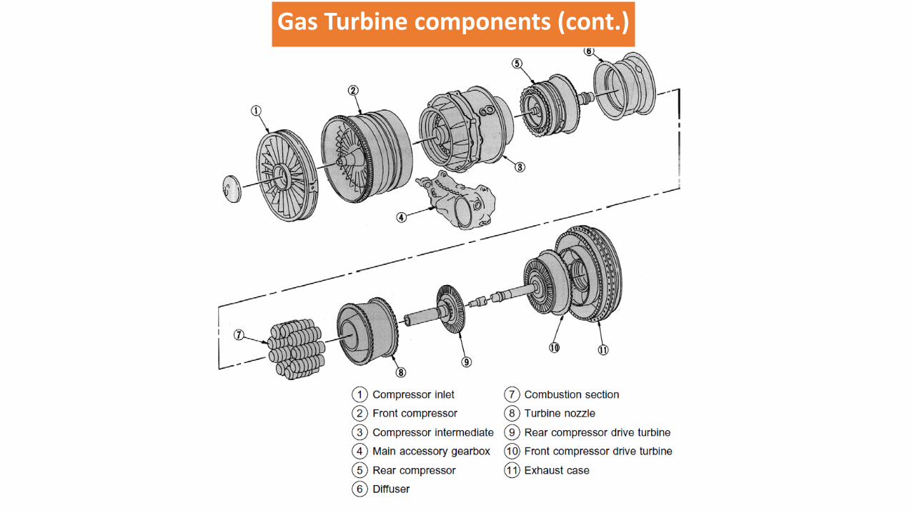
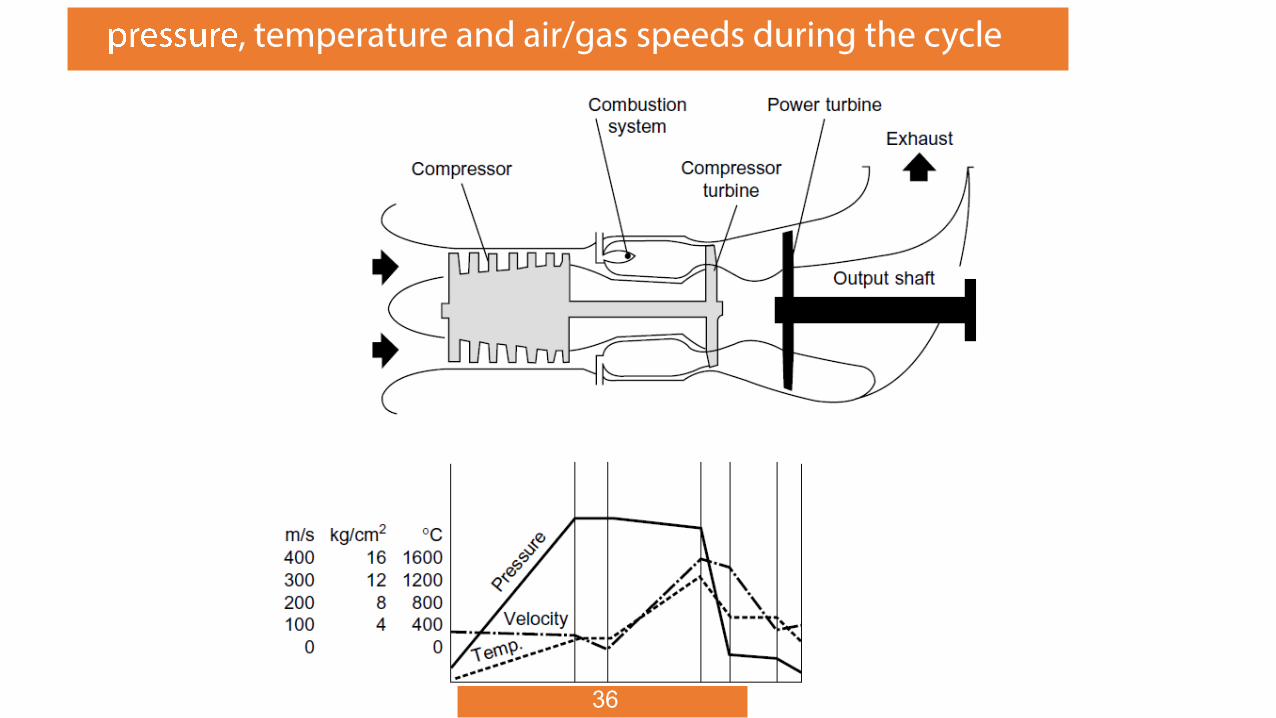
Gas Turbine components
A compressor to draw in and
compress atmospheric air.
A combustion system into
which fuel is injected, mixed
with the compressed air and
burned.
A compressor turbine which
absorbs sufficient power from
the hot gases to drive the
compressor.
A power turbine which absorbs
the remaining energy in the hot
gas stream and converts it into
shaft power.
20
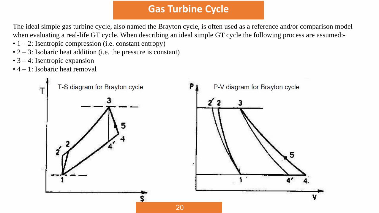
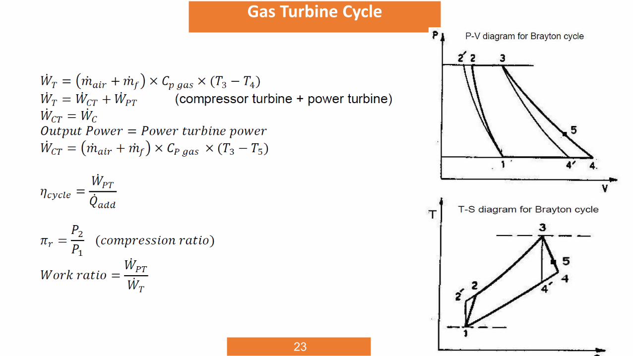
Gas Turbine Cycle
The ideal simple gas turbine cycle, also named the Brayton cycle, is often used as a reference and/or comparison model
when evaluating a real-life GT cycle. When describing an ideal simple GT cycle the following process are assumed:-
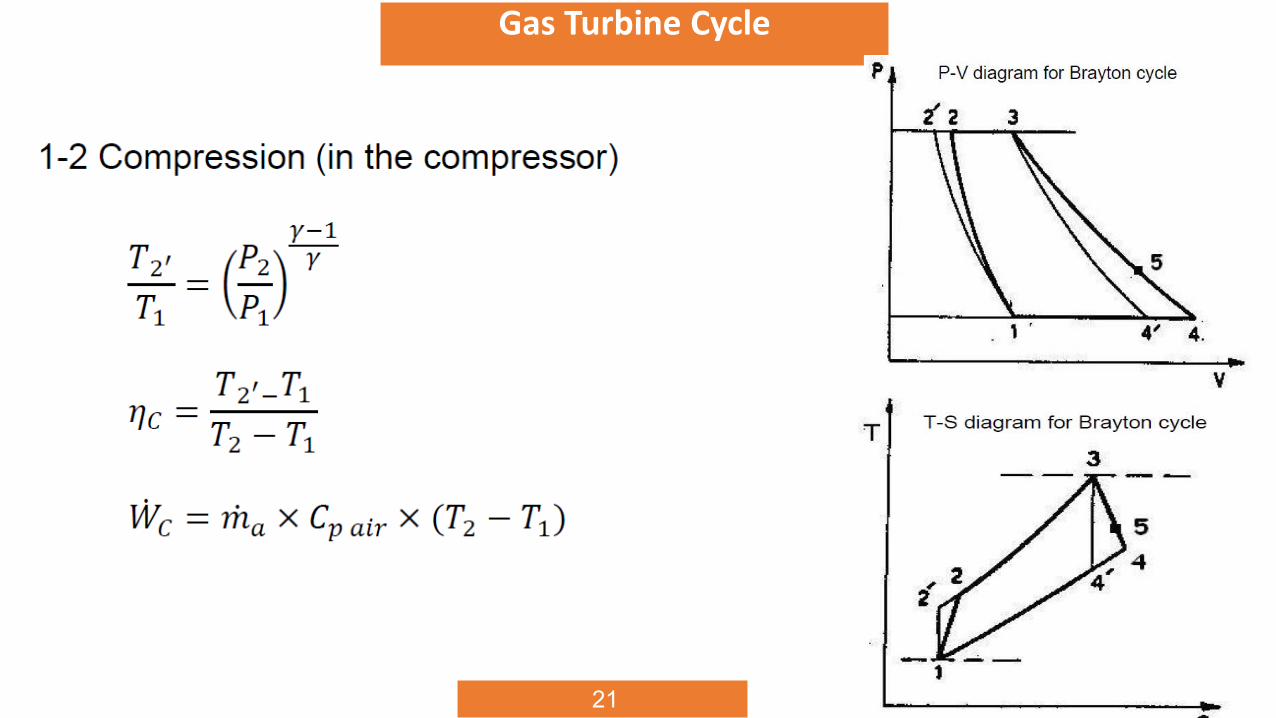
• 1 – 2: Isentropic compression (i.e. constant entropy)
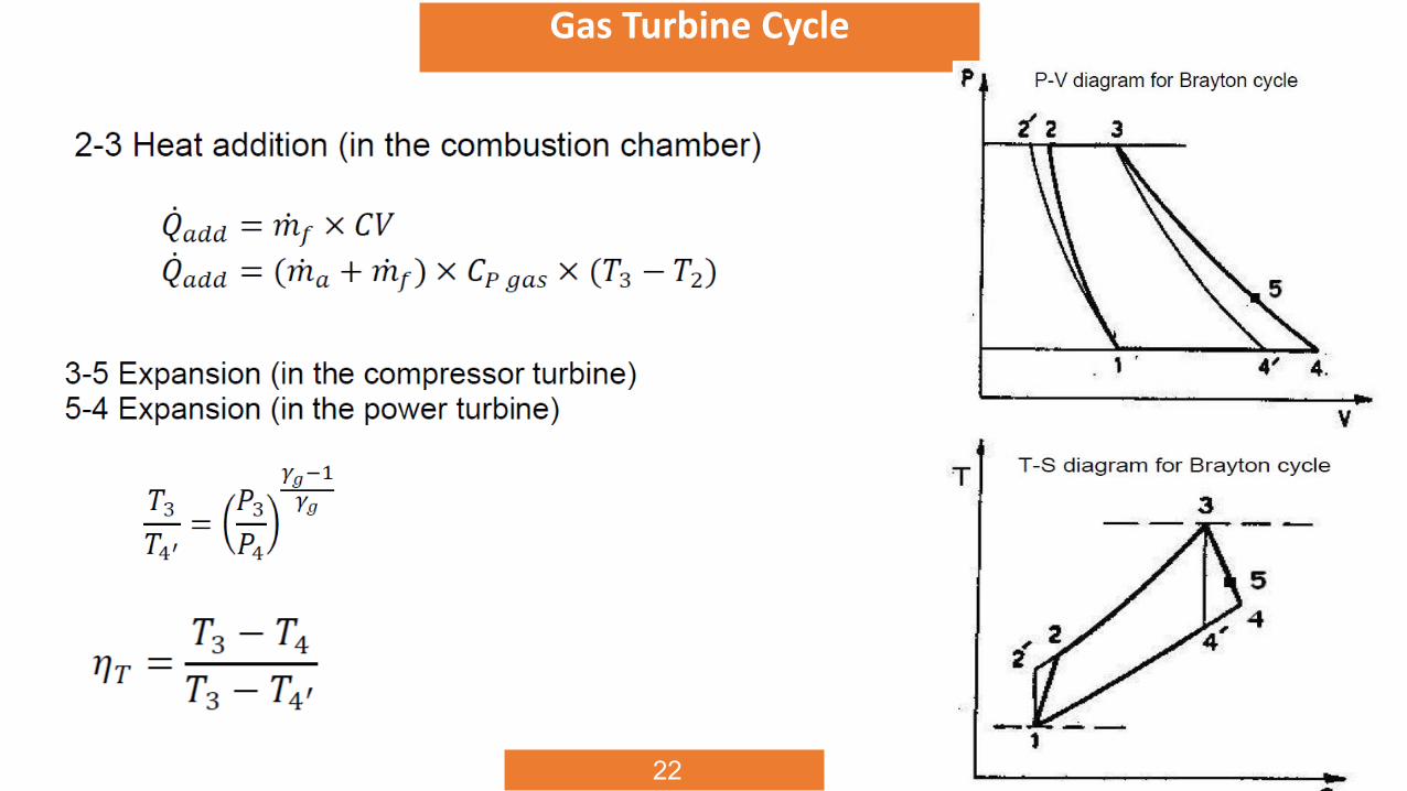
• 2 – 3: Isobaric heat addition (i.e. the pressure is constant)
• 3 – 4: Isentropic expansion
• 4 – 1: Isobaric heat removal
21
Gas Turbine Cycle
22
Gas Turbine Cycle
23
Gas Turbine Cycle
24
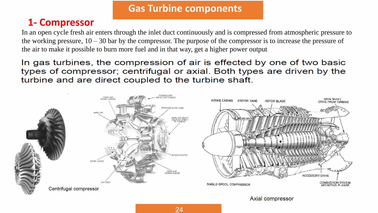
Gas Turbine components
1- CompressorIn an open cycle fresh air enters through the inlet duct continuously and is compressed from atmospheric pressure to
the working pressure, 10 – 30 bar by the compressor. The purpose of the compressor is to increase the pressure of
the air to make it possible to burn more fuel and in that way, get a higher power output
25
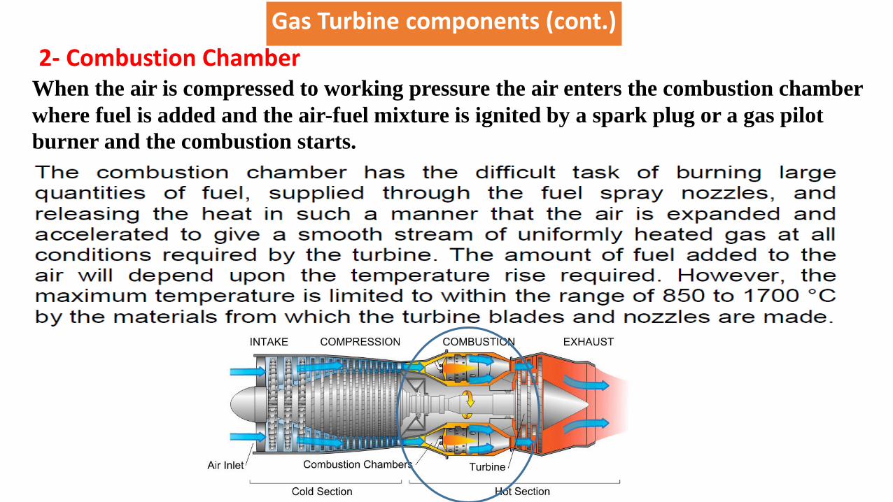
Gas Turbine components (cont.)
2- Combustion ChamberWhen the air is compressed to working pressure the air enters the combustion chamber
where fuel is added and the air-fuel mixture is ignited by a spark plug or a gas pilot
burner and the combustion starts.
26
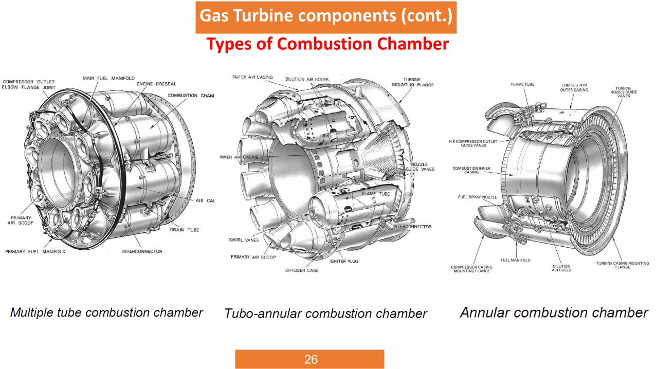
Gas Turbine components (cont.)
Types of Combustion Chamber
28
Gas Turbine components (cont.)
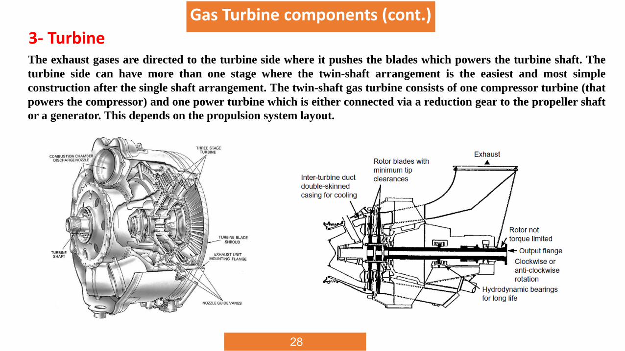
3- TurbineThe exhaust gases are directed to the turbine side where it pushes the blades which powers the turbine shaft. The
turbine side can have more than one stage where the twin-shaft arrangement is the easiest and most simple
construction after the single shaft arrangement. The twin-shaft gas turbine consists of one compressor turbine (that
powers the compressor) and one power turbine which is either connected via a reduction gear to the propeller shaft
or a generator. This depends on the propulsion system layout.
Gas Turbine components (cont.)
30
Gas turbine performance and efficiency (Losses)
The main differences between the Brayton cycle and the real gas turbine cycle is the losses
that occurs during the process.
1- Air friction losses will occur in the compressor, in any application about half of the
energy produced by the turbine is consumed by the compressor and electrical demands of
the accessories.
2- the combustion chamber and the turbine sections; thermal losses occur when heat is
transferring to the surrounding environment, mainly from the combustion chamber and the
turbine side;
3- combustion losses due to incomplete combustion of the added fuel;
4- several mechanical losses in all moving parts like bearings and auxiliary equipment
and pressure losses in all ducts will also occur.
31
Effects on Gas turbine performance and efficiency
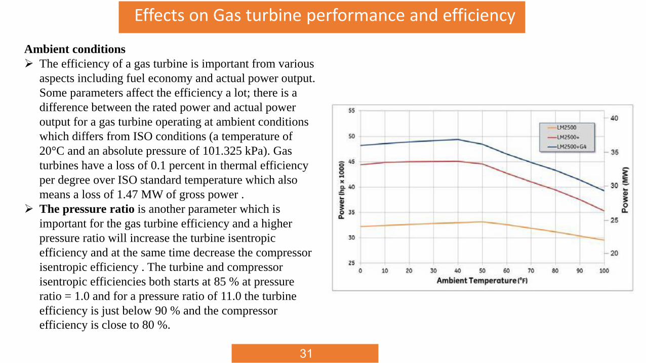
Ambient conditions
The efficiency of a gas turbine is important from various
aspects including fuel economy and actual power output.
Some parameters affect the efficiency a lot; there is a
difference between the rated power and actual power
output for a gas turbine operating at ambient conditions
which differs from ISO conditions (a temperature of
20°C and an absolute pressure of 101.325 kPa). Gas
turbines have a loss of 0.1 percent in thermal efficiency
per degree over ISO standard temperature which also
means a loss of 1.47 MW of gross power .
The pressure ratio is another parameter which is
important for the gas turbine efficiency and a higher
pressure ratio will increase the turbine isentropic
efficiency and at the same time decrease the compressor
isentropic efficiency . The turbine and compressor
isentropic efficiencies both starts at 85 % at pressure
ratio = 1.0 and for a pressure ratio of 11.0 the turbine
efficiency is just below 90 % and the compressor
efficiency is close to 80 %.
32
Gas turbine marine propulsion installation
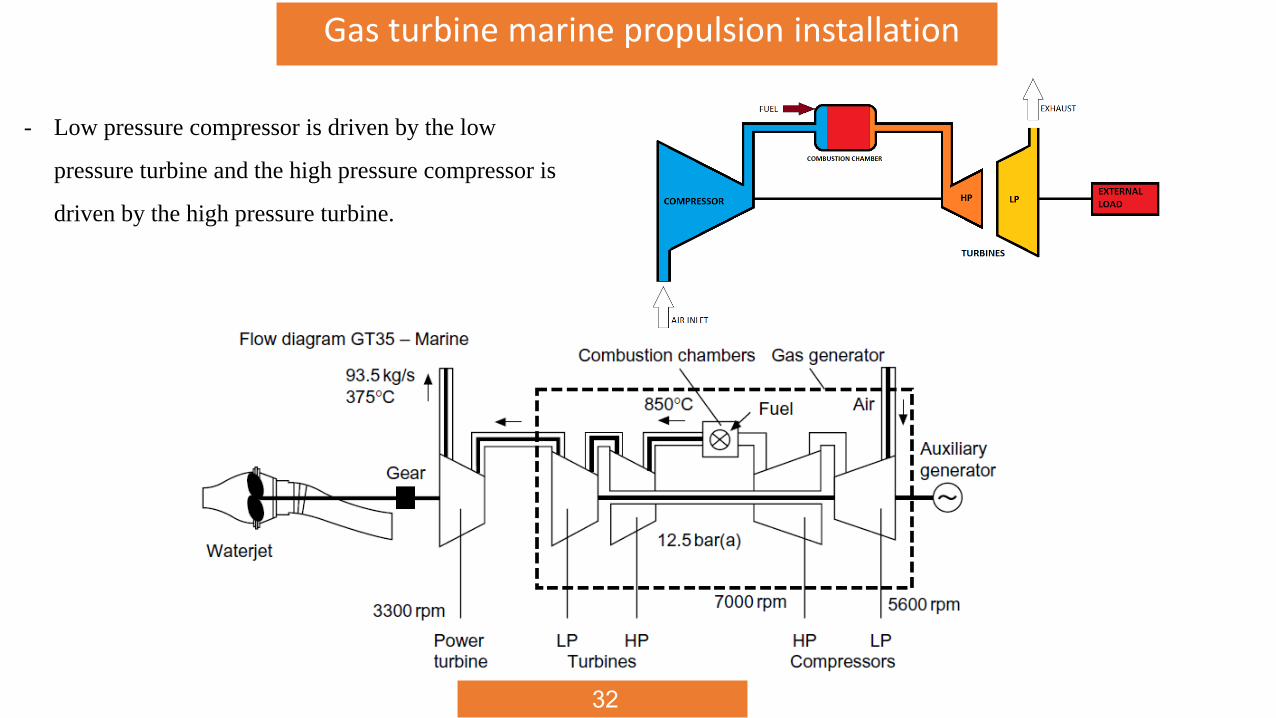
- Low pressure compressor is driven by the low
pressure turbine and the high pressure compressor is
driven by the high pressure turbine.
33
Gas turbine marine propulsion installation
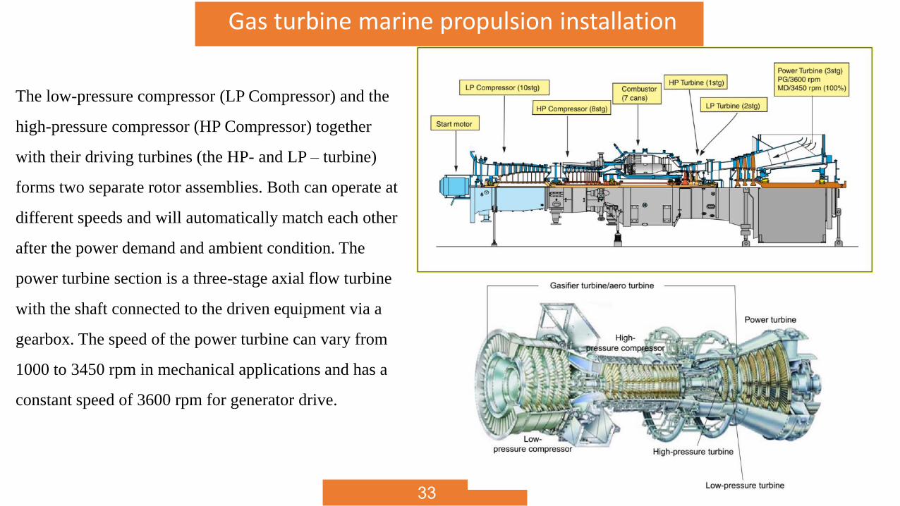
The low-pressure compressor (LP Compressor) and the
high-pressure compressor (HP Compressor) together
with their driving turbines (the HP- and LP – turbine)
forms two separate rotor assemblies. Both can operate at
different speeds and will automatically match each other
after the power demand and ambient condition. The
power turbine section is a three-stage axial flow turbine
with the shaft connected to the driven equipment via a
gearbox. The speed of the power turbine can vary from
1000 to 3450 rpm in mechanical applications and has a
constant speed of 3600 rpm for generator drive.
34
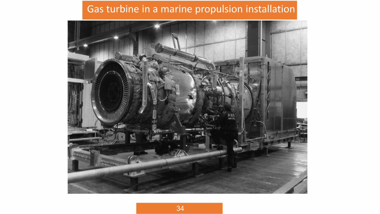
Gas Turbine components (cont.)Gas turbine in a marine propulsion installation
35
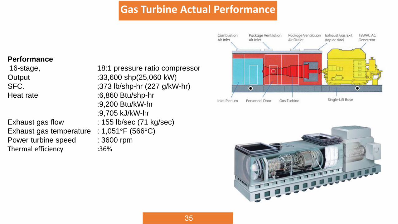
Gas Turbine Actual Performance
Performance
16-stage, 18:1 pressure ratio compressor
Output :33,600 shp(25,060 kW)
SFC. ;373 lb/shp-hr (227 g/kW-hr)
Heat rate :6,860 Btu/shp-hr
:9,200 Btu/kW-hr
:9,705 kJ/kW-hr
Exhaust gas flow : 155 lb/sec (71 kg/sec)
Exhaust gas temperature : 1,051°F (566°C)
Power turbine speed : 3600 rpmThermal efficiency :36%
36
37
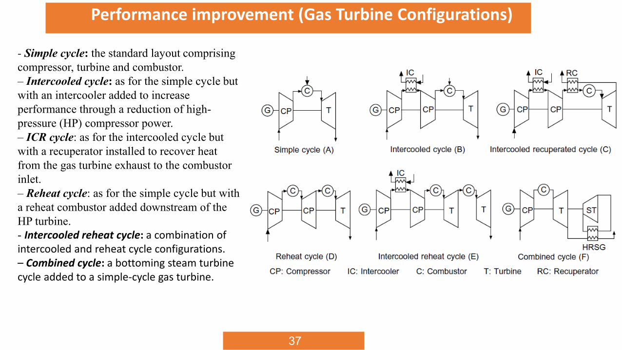
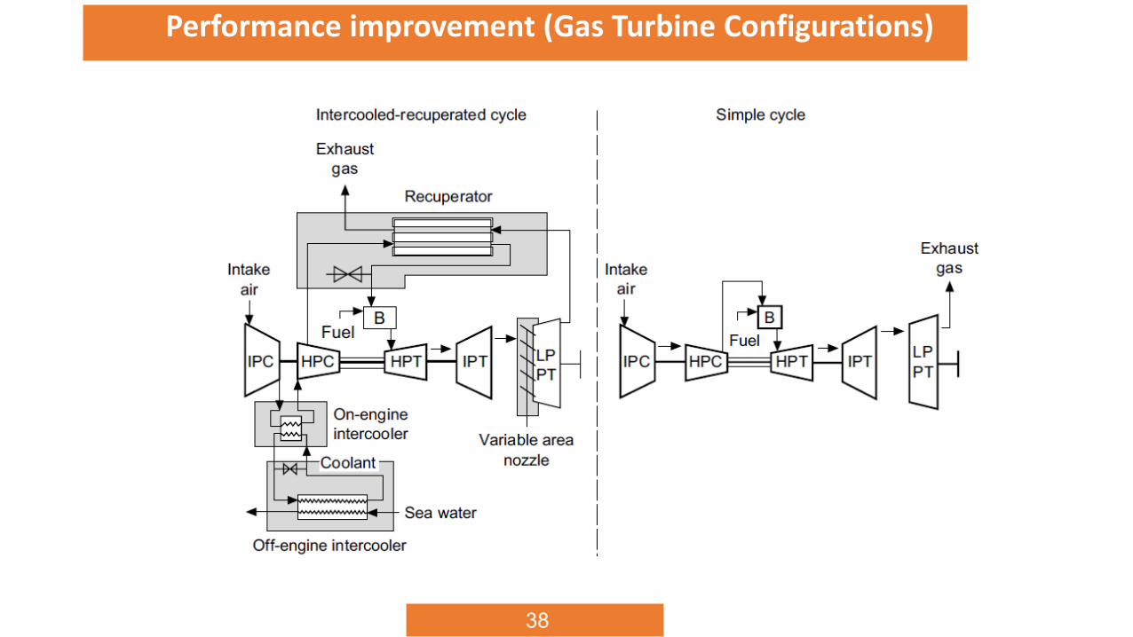
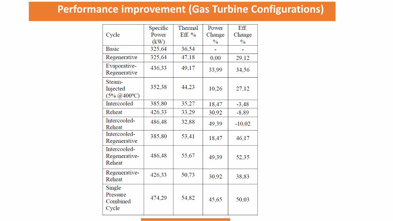
Performance improvement (Gas Turbine Configurations)
- Simple cycle: the standard layout comprising
compressor, turbine and combustor.
– Intercooled cycle: as for the simple cycle but
with an intercooler added to increase
performance through a reduction of high-
pressure (HP) compressor power.
– ICR cycle: as for the intercooled cycle but
with a recuperator installed to recover heat
from the gas turbine exhaust to the combustor
inlet.
– Reheat cycle: as for the simple cycle but with
a reheat combustor added downstream of the
HP turbine.
- Intercooled reheat cycle: a combination of intercooled and reheat cycle configurations.– Combined cycle: a bottoming steam turbine cycle added to a simple-cycle gas turbine.
38
Gas Turbine components (cont.)Performance improvement (Gas Turbine Configurations)
39
Gas Turbine components (cont.)Performance improvement (Gas Turbine Configurations)