marine and petroleum geology - zoltán sylvester · 2019-06-17 · z. sylvester et al. / marine and...
TRANSCRIPT

lable at ScienceDirect
Marine and Petroleum Geology 28 (2011) 716e727
Contents lists avai
Marine and Petroleum Geology
journal homepage: www.elsevier .com/locate/marpetgeo
A model of submarine channel-levee evolution based on channel trajectories:Implications for stratigraphic architecture
Zoltán Sylvester*, Carlos Pirmez 1, Alessandro CantelliShell Projects and Technology, Houston, TX 77001-0481, USA
a r t i c l e i n f o
Article history:Received 28 November 2009Received in revised form2 May 2010Accepted 25 May 2010Available online 2 June 2010
Keywords:Submarine channelsLateral migrationAggradationIncisionChannel-levee systemStratigraphic architectureChronostratigraphic diagramTurbidity current
* Corresponding author.E-mail address: [email protected] (Z. Sylv
1 Present address: Shell Nigeria E&P, Lagos, Nigeria
0264-8172/$ e see front matter � 2010 Elsevier Ltd.doi:10.1016/j.marpetgeo.2010.05.012
a b s t r a c t
Channel-levee systems are frequently interpreted as having a long history of cut-and-fill by channel-shaped features of different scales. Results from a simple geometric model based on a centerlinemigration algorithm combined with a vertical channel trajectory show that an incising-to-aggradingtrajectory of a single channel can produce realistic morphologies similar to systems observed on theseafloor and subsurface, including features such as a basal erosional surface, coeval inner and outerlevees, internal erosional boundaries, and terraces draped by inner levee deposits. Channel migrationresults in composite erosional surfaces that are distinct from topographic surfaces, and their formationdoes not require larger than usual erosional flows. Many submarine channels interpreted as underfitwere probably carved by flows similar to the ones that eroded and deposited the entire channel system.We suggest that the features of most submarine channel-levee systems do not require large temporalvariations in flow magnitude but can be explained by a simpler model whereby incision, migration andaggradation of a single channel form over time results in an apparently complex system.
� 2010 Elsevier Ltd. All rights reserved.
1. Introduction
In recent years, as high-resolution seafloor images and high-quality three-dimensional seismic datasets have increasinglybecome subjects of careful study, substantial progress has beenmade in understanding the morphology, stratigraphy, and evolu-tion of submarine channel-levee systems (e.g., Abreu et al., 2003;Babonneau et al., 2002; De Ruig and Hubbard, 2006; Deptucket al., 2003, 2007; Fildani et al., 2006; Kolla et al., 2007; Normarket al., 1998; Pirmez et al., 2000; Pirmez and Imran, 2003; Strauband Mohrig, 2008). However, some of the complexities that resultfrom long-term channel evolution and the interplay of channelincision, aggradation, lateral migration, and levee deposition, arestill poorly understood. These large, long-lived submarine channelsand valleys are often thought to have a complex history of cut-and-fill and a corresponding multi-scale hierarchy of erosional surfaces(Abreu et al., 2003; Hubbard et al., 2009;Mayall et al., 2006; Samuelet al., 2003). The scales of the erosional surfaces are sometimeslinked to flow size, larger cuts being eroded by larger flows and
ester)..
All rights reserved.
later filled by lower discharge or ‘underfit’ currents (Deptuck et al.,2003; Kolla et al., 2007). An analogous problem is the interpretationof the modern-day Grand Canyon topography: is it the result ofa series of extremely large floods, followed by a dramatic decreasein discharge, or the cumulative effect of long-term erosion bya river with discharges similar to the present-day Colorado River(e.g., Spencer and Pearthree, 2001).
Building on the increasing number of high-resolution seismicstudies that provide better constraints on channel evolution, we setout to investigate the origin of erosional surfaces in slope channelsystems and the relationships between geomorphic evolution andstratigraphic architecture. High-quality three-dimensional seismicdatasets that have been interpreted in detail (e.g., De Ruig andHubbard, 2006; Deptuck et al., 2003, 2007) suggest that:(1) within individual submarine channel systems, channel sizevariability is relatively small, (2) channels migrate in a systematicway and their placement is far from random (Labourdette, 2008;Labourdette and Bez, 2010). Starting from such observations, wehave developed a three-dimensional geometric model for subma-rine channel-levee systems. Our model accounts for lateral channelmigration, incision, aggradation, channel and overbank deposits,cutoffs, and includes a simple depth-dependent facies distribution.While it shares some characteristics with existing three-dimen-sional models of fluvial (Cojan et al., 2005; Pyrcz and Deutsch,

dxdz
channel form 1 channel form 2
erosiondeposition
channel centerpointoverbank
Fig. 1. Simple two-dimensional model of a migrating channel form (with constantdimensions) and flat overbank surface. Surface resulting after one time step (withnegative dz, i.e., erosion) is shown with thick black line.
Z. Sylvester et al. / Marine and Petroleum Geology 28 (2011) 716e727 717
2005; Pyrcz et al., 2009; Willis and Tang, 2010) and submarinechannels (Pyrcz and Strebelle, 2006; Labourdette, 2008;Labourdette and Bez, 2010; McHargue et al., 2011), our modelincludes several important new features: (1) development of valleymorphology through long-term channel erosion; (2) long-termlevee deposition resulting in consistent channel-levee and inner-to-outer levee relationships; and (3) existence of a realisticgeomorphic surfacewith a single, unfilled channel form at all times.This last feature allows us to represent the model results not only inphysical stratigraphic space but in a precise three-dimensionalchronostratigraphic framework as well. The purpose of this paper isto describe this model and discuss the implications for channel-levee morphology and stratigraphy.
Although the model output examples presented here are notspecific to the outcrops visited during the SEPM Research Confer-ence focusing on Stratigraphic Evolution of Deep-Water Architec-ture (Fildani et al., 2009), large-scale geometries generated by ourmodel are comparable to some of the channel-levee systems of theMagallanes Basin exposed in southern Chile. The coarse-grainedchannel deposits of the Cerro Toro Formation are part of a majorchannel-levee system that follows the axis of an elongated forelandbasin (Hubbard et al., 2008). The best subsurface analog for thisformation is the axial channel belt of the Austrian Molasse Basin(De Ruig and Hubbard, 2006; Hubbard et al., 2009). The scale ofthese axial channel belts renders even the largest outcrops toolimited to decipher the channel-belt-scale, three-dimensionalarchitecture, but the channels of the Molasse Basin are well imagedand mapped in three-dimensional seismic data, and show consis-tent channel migration and aggradation. Outcrops of the Tres PasosFormation provide examples of the outcrop expression of laterallymigrating, much smaller sinuous channels (Shultz et al., 2005, theirFig. 19), with details that resemble some of the model outputs.Despite the huge differences in scale, grain size, and basinal setting,both of these channel systems can be modeled through theevolution of a simple channel-overbank surface, a conceptdescribed in the following sections.
2. Two-dimensional model
2.1. Description
As a starting point, we attempt to reproduce a typical strike-oriented cross section of a channel-levee system. Cross sections ofsubmarine channels in 3D seismic data and outcrops often seemhighly complicated, showing a number of erosional surfaces ofdifferent scales (e.g., Campion et al., 2000; Deptuck et al., 2003;Mayall et al., 2006). However, in the few cases where it is possibleto map individual channel forms over relatively large distances suchas on shallow, high-resolution seismic data (Deptuck et al., 2003,2007), channel forms of individual systems tend to have a charac-teristic, relatively constant size and shape. Furthermore, migration ofa single channel shape, with varying degrees of aggradation andlateral migration, seems to create the complex channel stackingpatterns observed in these well-documented case studies. Clark andPickering (1996, their Fig. 8) suggest that various channel complexesresult as a function of lateral versus vertical stacking of a singlechannel through time. If we replace the channel bodies with emptychannel forms cut into a flat ‘overbank’ surface, in a similar mannerto De Ruig and Hubbard (2006, their Fig. 11), this concept can beformulated in the framework of topographic surfaces that changethrough time due to contemporaneous erosion and deposition.
A parabola is used for the parameterization of the erosionalchannel form (Fig. 1). The channel centerpoint is the channelmidpoint at the top. At each time step t, the new location of thecenterpoint is defined by a horizontal component dx and a vertical
component dz applied to the coordinate at the previous time step. Ifdz is positive, the channel form aggrades and its shape and sizeremain the same; if dz is negative, the channel form is stilldescribed by the same parabola, but the distance between thechannel base and the flat overbank surface becomes larger. Theadditional erosional depth is added to the channel form byextending the parabola upward, to the overbank surface (right sideof channel in Fig. 1). This modeling step mimics channel bankerosion through repeated downcutting and bank failure on one sideof a migrating channel, a process that is probably important in mostsubmarine channels and valleys (e.g., Deptuck et al., 2003, theirFig. 10). While several conceptual models that have been previ-ously drawn up illustrate the relative importance of aggradationand lateral migration for large-scale channel architecture (e.g.,Clark and Pickering,1996; Kolla et al., 2007), ourmodel includes thepossibility of channel incision as well.
The parameters x and z define the channel trajectory. The ‘channeltrajectory’ concept is similar to the shoreline trajectory: just likeshoreline trajectories are useful for describing shoreline migrationand the resulting sequence stratigraphic patterns in a dip section(Helland-Hansen and Martinsen, 1996; Kim et al., 2006; Wolinsky,2009), channel trajectories can be used to conceptualize and quan-tify channel evolution in a slope-parallel section. Long-term channelevolution is likely to result in a horizontal channel trajectorycomponent (dx) that changes sign several times as the direction ofmigration changes at a given location. In contrast, some seismicstudies (Deptuck et al., 2003, 2007; Hubbard et al., 2009) suggestthat the vertical component of the channel trajectory is unlikely tochange sign so frequently, and often it consists of a single incision-aggradation cycle, with no clear evidence for numerous large-scalereincisions. For sake of simplicity, the vertical component of thechannel trajectory is modeled here as a single incision-aggradationcycle (Fig. 2). However, if deemed necessary, vertical trajectories ofany complexity, e.g., withmultiple cycles of incision and aggradationcan be modeled. Fig. 2 shows the result from a horizontal channeltrajectory that is sinusoidal through time, combined with one inci-sion-to-aggradation cycle in the vertical dimension.
Although the model described until now is useful for visualizingthe large-scale stratigraphic architecture that corresponds todifferent channel trajectories, it has two important limitations.First, it does not produce realistic levee architectures: the overbanklayers are always horizontal and are only deposited if the channel isaggrading. Second, the parabolic channel form is always concave-up and intersects the overbank area at a sharp angle. This isreasonable if erosion predominates, and the parabola is probablya good approximation of entirely erosional channel forms, butchannel deposits usually do not have the sharp-edged wedge shapeseen in Fig. 1. In fluvial channels, deposition occurs largely on theinner sides of meander bends, and the resulting topographicsurface tends to be smooth and convex-up (e.g., Allen, 1985). Toaccount for this geometry, a depositional channel form, based ona Gaussian curve and inspired by the work of Imran et al. (1998), is

Fig. 2. Stratigraphic architecture (a) resulting from moving a constant channel form through a single incision-aggradation cycle in the vertical direction and several sweep andswing cycles in the horizontal direction, shown in (b). Dashed rectangle in (b) shows the time of aggradation (that is preserved in the stratigraphy). x and z are the coordinates in thehorizontal and vertical directions, respectively.
Z. Sylvester et al. / Marine and Petroleum Geology 28 (2011) 716e727718
used to create convex-up surfaces where deposition occurs (Fig. 3).While Imran et al. (1998) use Gaussians for both deposition anderosion, we prefer the parabola for the erosional shape, mostlybecause quadratic erosional surfaces are easily extended upwards.Deposition takes place where the depositional channel form liesabove the preexisting topography.
To create more realistic levee geometries, during each time step,levee deposits are modeled as wedges that linearly thin away fromthe channel (Fig. 3). Simplified sediment transport equationssuggest exponential decrease of turbidite bed thickness (e.g.,McCave and Swift, 1976), and of fluvial levee thickness (Pizzuto,1987) away from the channel. Therefore, from a theoretical pointof view, exponential thinning of levee layers is preferable to a linearmodel. However, Skene et al. (2002) have shown that, for themajority of the studied submarine channel-levee systems, the
deposition
erosion
initial channel form
new surface = previous surface + depositional form
new surface = previous surface - erosional form
levee deposition
after five steps
Fig. 3. Illustration of five time steps using the enhanced two-dimensional model. Onlylateral migration (no incision/aggradation) is present in this case. The diagrams for thefirst and second time steps illustrate how the algorithm works.
exponential model is statistically indistinguishable from the linearone. Thus, for the purposes of the present model, a linear thinningof the individual levee layers is a reasonable approximation,although the model can be easily modified to include other leveethickness decay functions. Additional details of levee development,such as the enhanced flow stripping and increased deposition onouter banks, with the resulting levee asymmetry (Straub et al.,2008), are not present in the model.
Levee layers drape the preexisting topography, and, as a result,they modify the surface morphology through simple verticalaggradation. In contrast with the channel forms that havea constant surfacemorphology, it is the shape of the levee layer thatstays the same, and the surface expression of the levee layer isvariable, depending on preexisting topography.
During aggradation, overbank deposits close to the channelmust be deposited at the same rate as the channel is aggrading ifthe channel relief is to remain the same over time. This also meansthat the levee thicknesses deposited at each time step have tomatch approximately the dz components of the channeltrajectory.
2.2. Results
If there is no incision or aggradation (dz¼ 0), the two-dimen-sional model should result in a point-bar like overall architecture(Fig. 3). Overbank layers behave as drapes. As a result, the steppederosional relief over the initial left channel margin is preservedduring levee deposition. If the channel migrates laterally, deposi-tion takes place along the inner bank and erosion occurs along theouter bank. The depositional channel form will determine thechannel morphology on the inner bank, and the erosional channelsurface will shape the cutbank. The resulting channel cross sectionbecomes asymmetric. Levee deposits in the resulting modelsdirectly link to fine-grained layers (drapes) that are interbeddedwith the channel deposits (Fig. 3).
Despite the simplicity of this two-dimensional model, complexgeometries and relationships between inner and outer levees resultwhen the channel trajectory is more complicated. If we assume thatthe vertical component of the channel trajectory consists of anincisional phase followed by an aggradational phase, and thehorizontal component includes several cycles of back-and-forthmovement, as a result of channel migration (swing and sweep), thearchitecture will have a number of large, composite and time-transgressive erosional surfaces (Fig. 4; see also Discussion).Erosional remnants on the left side of the system develop duringthe incisional phase (Fig. 5). The remnants form terraces that areoften preserved throughout the evolution of the system; leveedeposits drape these terraces. The next step is to populate thelayers with a sedimentary facies or a rock property (e.g., grain-size

10 m
10 m
100 m
10 m
100 m
10 m
d
e
f
0 10 20 30 40 50 60 70 80 90 100-20
-15
-10
-5
0
5
10
15
20
25
30
500 550 600 650 700 750 800
0
20
40
60
80
100
time
dept
h (m
)
time
step
s
x (m) 500 550 600 650 700 750 800
-20
-15
-10
-5
0
5
10
15
20
25
30
dept
h (m
)
x (m)
a b c
detail in (f)
inner levee
outer levee
12
3 4
5
1
2
3
4
5
12
3 4
5
12
3 4
5
Fig. 4. Example of a cross section generated with the two-dimensional model. (a) Vertical component of the channel trajectory, consisting of an initial incisional phase and a lateraggradational phase, with a number of intervening periods with no vertical displacement. (b) Horizontal component of the channel trajectory: a sinusoidal curve with a drift towardthe right, and a shorter-term back-and-forth movement due to swing and sweep. (c) Combining the vertical and horizontal components gives the actual channel trajectory.(d) Architecture of the channel-levee system built with the trajectory shown in (c). The colors show a depth-dependent facies distribution (green¼ channel lag/base deposits;yellow¼ sand; brown¼ shale). (e) Architecture colored by time (dark red¼ old; white¼ young). Large composite erosional surfaces shownwith thick black lines. Note that no erosionoccurs in the upper left side of the system, despite the complicated architecture that links the outer and inner levees. (f) Detail of the architecture, without any vertical exaggeration.All erosional surfaces shown with thick black lines.
Z. Sylvester et al. / Marine and Petroleum Geology 28 (2011) 716e727 719
distribution, porosity, permeability). Because the model trackselevation above the thalweg at all points in time, it is easy to relatesediment properties to channel topography. An elevation-depen-dent facies model, which assumes decreasing grain size as heightabove channel thalweg increases, is a simple method used here toillustrate the large-scale distribution of facies (Fig. 4d).
3. Three-dimensional model
The two-dimensional model is a useful tool to understand theinfluence of the channel trajectory on the geometries of channeland overbank deposits. However, some of the complexity thatresults from the strong three-dimensionality of sinuous submarine

Fig. 5. Time evolution of the facies architecture of the channel-levee system shown in Fig. 4. Numbers in the upper right corners represent time steps. Facies color code is the sameas in Fig. 4.
Z. Sylvester et al. / Marine and Petroleum Geology 28 (2011) 716e727720
channels is not represented in the 2D model. For example, in realsystems it is common to intercept the same channel several timeswith a cross section, but there can be only one channel formpresent at any time and at any level in the 2D model cross sections.Therefore, the obvious next step is to extend the model to threedimensions.
3.1. Description
The three-dimensional model combines the vertical componentof the channel trajectory with a set of consistently migratingchannel centerlines. For centerline generation, we adopted thekinematic channel evolution model of Yi (2006), where the depth-averaged flow field in a sinuous channel is calculated using steadyflow in a straight channel as the base state. The channel migrationrate is linked to the flow field at each point along the centerline. Themodel can be adopted for simulating both submarine and fluvialchannels (Yi, 2006). Key geometric characteristics of submarinechannels are comparable to those of fluvial channels (Pirmez andImran, 2003), and subtle differences in the plan-view centerlinemigration patterns are unlikely to affect the overall three-dimen-sional morphology and stratigraphy. Instead, the important differ-ences arise from the more pronounced levee development andhigher rates of aggradation in submarine systems (see Discussionbelow). Therefore, any centerline migration model (e.g., Frascatiand Lanzoni, 2009; Howard and Knutson, 1984; Ikeda et al., 1981;Sun et al., 2001; Zolezzi and Seminara, 2001) that produces regu-larly migrating sinuous patterns can be used to illustrate the three-
dimensional complexities of the modeled channel-levee systems.The differences in plan-view migration patterns of fluvial andsubmarine channels, for example meander asymmetry, frequencyof compound meanders and of neck-cutoffs, are still poorlyunderstood and are not the subject of this study.
Centerline migration algorithms, including the one used here,always result in erosion of the outer banks and deposition on theinner banks. However, evidence from flume experiments andseismic data suggest that turbidity currents can also deposit sedi-ment preferentially on the outer banks (Kane et al., 2008; Straubet al., 2008). It is likely that such ‘plastering’ occurs mostly whenthe flows are out of equilibrium with the channel. Outer-bankdeposition, if coupled with erosion of the inner bank, results inreduction of sinuosity (Kane et al., 2008; Straub et al., 2008); if theinner bank erosion is limited or absent and therefore it does notbalance the outer-bank deposition, asymmetric filling of thechannel is the result. This process is not modeled by currentcenterline migration algorithms and it is missing from the channeltrajectory model described here; our model focuses on theprocesses that form, maintain and migrate the channel, rather thanthe flow types likely to be characteristic of channel abandonmentand filling.
For relatively short stretches of the channel system, the verticalcomponent of the channel trajectory is assumed constant. Thisapproach is consistent with observed channel longitudinal depthprofiles that tend to be approximately parallel in along-channelcross sections for several tens of kilometers (e.g., Deptuck et al.,2007). Inclusion of realistic along-channel variations of slope

Z. Sylvester et al. / Marine and Petroleum Geology 28 (2011) 716e727 721
(e.g., knickpoints) would certainly make the model more realisticand would change some of the details of the three-dimensionalarchitecture. However, all presently available centerline modelsassume spatially constant slope along every centerline.
The surfaces corresponding to the erosional channel form, thedepositional channel form, and the levee deposits are calculated foreach time step, using the same parameterizations as in the 2Dmodel. We used Matlab� to generate surfaces and to visualize theresults.
Fig. 6. (a) Cross section from a model generated with 100 centerlines and an incisional- to afacies model. (b) The same cross section colored by time. (c) Chronostratigraphic (Wheeler) dIndus Fan (for context, see Deptuck et al., 2003), showing similarities with the model resultsa result, there is no major relief difference left between the outer and inner levees.
3.2. Results
A model has been generated using one hundred channelcenterlines and one incision-to-aggradation cycle, with a smooth,sinusoidal transition between incision and aggradation (Figs. 6, 7,8aec). The result is a channel-levee system with a compositeerosional surface with scalloped margins (Fig. 9). This erosionalsurface develops during both the incisional and aggradationalphases, and it does not require a change in the characteristic
ggradational vertical channel trajectory. The colors reflect qualitative, depth-dependentiagram. (d) Representative seismic cross section from channel-levee system CLS3 of the. This system has gone through more aggradation than the one shown in (a) and (b); as
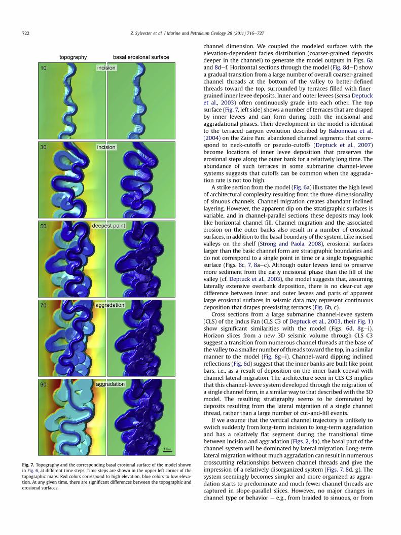
Fig. 7. Topography and the corresponding basal erosional surface of the model shownin Fig. 6, at different time steps. Time steps are shown in the upper left corner of thetopographic maps. Red colors correspond to high elevation, blue colors to low eleva-tion. At any given time, there are significant differences between the topographic anderosional surfaces.
Z. Sylvester et al. / Marine and Petroleum Geology 28 (2011) 716e727722
channel dimension. We coupled the modeled surfaces with theelevation-dependent facies distribution (coarser-grained depositsdeeper in the channel) to generate the model outputs in Figs. 6aand 8def. Horizontal sections through the model (Fig. 8def) showa gradual transition from a large number of overall coarser-grainedchannel threads at the bottom of the valley to better-definedthreads toward the top, surrounded by terraces filled with finer-grained inner levee deposits. Inner and outer levees (sensu Deptucket al., 2003) often continuously grade into each other. The topsurface (Fig. 7, left side) shows a number of terraces that are drapedby inner levees and can form during both the incisional andaggradational phases. Their development in the model is identicalto the terraced canyon evolution described by Babonneau et al.(2004) on the Zaire Fan: abandoned channel segments that corre-spond to neck-cutoffs or pseudo-cutoffs (Deptuck et al., 2007)become locations of inner levee deposition that preserves theerosional steps along the outer bank for a relatively long time. Theabundance of such terraces in some submarine channel-leveesystems suggests that cutoffs can be common when the aggrada-tion rate is not too high.
A strike section from the model (Fig. 6a) illustrates the high levelof architectural complexity resulting from the three-dimensionalityof sinuous channels. Channel migration creates abundant inclinedlayering. However, the apparent dip on the stratigraphic surfaces isvariable, and in channel-parallel sections these deposits may looklike horizontal channel fill. Channel migration and the associatederosion on the outer banks also result in a number of erosionalsurfaces, in addition to the basal boundary of the system. Like incisedvalleys on the shelf (Strong and Paola, 2008), erosional surfaceslarger than the basic channel form are stratigraphic boundaries anddo not correspond to a single point in time or a single topographicsurface (Figs. 6c, 7, 8aec). Although outer levees tend to preservemore sediment from the early incisional phase than the fill of thevalley (cf. Deptuck et al., 2003), the model suggests that, assuminglaterally extensive overbank deposition, there is no clear-cut agedifference between inner and outer levees and parts of apparentlarge erosional surfaces in seismic data may represent continuousdeposition that drapes preexisting terraces (Fig. 6b, c).
Cross sections from a large submarine channel-levee system(CLS) of the Indus Fan (CLS C3 of Deptuck et al., 2003, their Fig. 1)show significant similarities with the model (Figs. 6d, 8gei).Horizon slices from a new 3D seismic volume through CLS C3suggest a transition from numerous channel threads at the base ofthe valley to a smaller number of threads toward the top, in a similarmanner to the model (Fig. 8gei). Channel-ward dipping inclinedreflections (Fig. 6d) suggest that the inner banks are built like pointbars, i.e., as a result of deposition on the inner bank coeval withchannel lateral migration. The architecture seen in CLS C3 impliesthat this channel-levee system developed through the migration ofa single channel form, in a similar way to that describedwith the 3Dmodel. The resulting stratigraphy seems to be dominated bydeposits resulting from the lateral migration of a single channelthread, rather than a large number of cut-and-fill events.
If we assume that the vertical channel trajectory is unlikely toswitch suddenly from long-term incision to long-term aggradationand has a relatively flat segment during the transitional timebetween incision and aggradation (Figs. 2, 4a), the basal part of thechannel system will be dominated by lateral migration. Long-termlateral migrationwithoutmuch aggradation can result in numerouscrosscutting relationships between channel threads and give theimpression of a relatively disorganized system (Figs. 7, 8d, g). Thesystem seemingly becomes simpler and more organized as aggra-dation starts to predominate and much fewer channel threads arecaptured in slope-parallel slices. However, no major changes inchannel type or behavior e e.g., from braided to sinuous, or from

Fig. 8. (a) Basal composite erosional surface of the model shown in Fig. 6. Red colors correspond to high elevation, blue colors to low elevation. (b) Topographic surface at time ofmaximum incision. (c) Topographic surface at the end of aggradation. (def) Horizontal sections through stratigraphy, from base to top. Lines represent stratigraphic surfaces; colorcoding for facies is identical to that of Fig. 4d. Locations of sections are shown in Fig. 6a. (gei) Seafloor-parallel horizon slices through channel-levee system CLS3 (as defined inDeptuck et al., 2003), from base to top, from a volume of seismic coherence (black¼ low coherence; white¼ high coherence). Areas shown in brown are flat-lying inner levees interraces; areas colored in light yellow are zones of channel migration. Compare with the stratigraphic sections in figures (def).
Z. Sylvester et al. / Marine and Petroleum Geology 28 (2011) 716e727 723
frequent filling and cutting to reduced cut-and-fill e are needed forthis transition to take place.
4. Discussion
4.1. Erosional surfaces: basic channel form versus compositesurfaces
Submarine channel systems are often analyzed using a hierar-chical approach (Gardner et al., 2003; Abreu et al., 2003; Campion
et al., 2000; Mayall et al., 2006): individual turbidite beds stack toform channel fills; channels are parts of the fills of larger erosionalfeatures; and all these elements can be located inside an even largererosional form.While hierarchical models are useful to describe thewide range of scales present in these systems and to build reservoirmodels with the appropriate level of detail, it is important torecognize that boundaries between hierarchical levels are oftenarbitrary and that large erosional surfaces do not always reflectsome allogenic influence, but can be the result of channel migration(e.g., Figs. 6 and 8).

Fig. 9. Three-dimensional views of the surfaces shown in map view in Fig. 8aec.(a) Topography at time of maximum incision; (b) Final topography; (c) Basal erosionalsurface. Contour interval is 20 m.
200 m
2000 m
final topographytopography at maximum incisionerosional base
Fig. 10. Example cross sections showing the difference between the basal erosionalsurface, which is a stratigraphic surface, and the topographic surface at the time ofmaximum incision, which is a geomorphologic or time surface.
Z. Sylvester et al. / Marine and Petroleum Geology 28 (2011) 716e727724
The channel trajectory model highlights the fundamentaldifference between erosional surfaces related to a characteristicdischarge, and erosional surfaces that are the result of long-termchannel migration. The first type is the same as the basic channelform of a system, corresponds to a bathymetric feature on theseafloor, and within one system, it is likely to have a relatively lowvariation in size. Systematic channel migration happens at thisscale, as it is driven by the flows that determine the basic channelsize. The second type of surface records the migration through timeof the basic channel form and therefore its scale and geometry isa function of the channel migration history. These larger erosionalsurfaces are time-transgressive and do not exist at any time asbathymetric features on the seafloor. A valley that is larger than thebasic channel form does develop during the incisional phase (e.g.,time step 70 in Figs. 7 and 9a) but there are significant differencesbetween this time surface and the composite basal erosionalsurface (Fig. 10).
4.2. Erosional surfaces and flow size
The channel trajectory model shows that realistic valleys andvalley fill architectures can develop while the average dischargeremains approximately the same. Smaller channels inside a largererosional cut are often interpreted as the result of a major reductionin flow size (Deptuck et al., 2003; Kolla et al., 2007). While this is
clearly a possibility, we suggest that large changes in averagedischarge are not necessary to explain most of the features weobserve in such systems; a long-term switch from somewhaterosional to slightly depositional flows is sufficient. Plan-viewexpressions of slope channels provide evidence that the largeerosional surfaces do not result frommuch larger flows. If the valleysurface was created by high-discharge flows, one would expect tosee a sinuous plan view, with valley walls that are roughly parallelto each other. This is not the case however: most such boundariesare irregular and strongly scalloped (Babonneau et al., 2002;Deptuck et al., 2003; McHargue et al., 2011). Most of these scal-lops result from the widening of the valley wall by the migratingsinuous channel (Fig. 7). Althoughmost of thewidening and scallopdevelopment occurs during incision, new scallops can developduring aggradation as well. A large-discharge channel or valleyshould also undergo at least some lateral migration; however, nosuch large-scale valley migration deposits have been described sofar. Further updip, where the channel-levee systems becomelargely non-depositional submarine canyons, there is evidence thatthe size of the canyons is not related to flow size (Normark andCarlson, 2003).
Flow discharge frequency data is not available from submarinechannels, although indirect evidence based on the thickness andgrain size of overbank deposits suggests relatively little flow vari-ability over time in the case of the Amazon channel-levee system(Pirmez and Imran, 2003). The channel trajectory model shows thatthe complex stratigraphy of a channel-levee system such as seen inthe Indus Fan (Figs. 6, 8) can be reproduced with simple rules. It issufficient to have a single channel size through the entire evolutionof the channel-levee system, suggesting that there is no need forlarge variations in flow size.
4.3. Vertical channel trajectory and reincisions
A necessary condition for the formation of typical channel-leveearchitectures (Figs. 4, 6) is that the vertical channel trajectoryfollows a long-term, relatively smooth cycle of net incision, fol-lowed by net aggradation. Long-term net incision can result fromadjustment to a smooth equilibrium profile during early channelevolution, following e or during e tectonic deformation (Heiniöand Davies, 2007; Clark and Cartwright, 2009), and after channelavulsion events (Pirmez et al., 2000). The cause for a switch to theaggradational phase is still unclear. Once the channel-levee system

0 100 200 300 400 500 600 7000
10
20
30
40
50
60
70
80
90
100
lateral migration (m)
aggr
adat
ion
(m) CF17 to CF10
CF10 to CF5
aggradation =
1/7 x lateral m
igration
Fig. 11. Aggradation plotted against lateral migration for two time intervals, BeninMajor channel-levee system. Measurements, made on maps and along-channelsections of Deptuck et al. (2007), represent the maximum lateral displacements ofchannel bends in plan view (lateral migration), and vertical distances (aggradation)from channel form (CF) 17 to CF 10 and from CF 10 to CF 5. Error bars correspond totwo standard deviations.
Z. Sylvester et al. / Marine and Petroleum Geology 28 (2011) 716e727 725
reaches equilibrium (the bottom of the incision-aggradation cycle,Fig. 4a), the switch to aggradation may be caused by: (a) reducedslope due to structural deformation, (b) relatively small, butsystematic changes in flow properties, as caused by delta pro-gradation or relative sea-level changes. Although the idea thatchannel behavior, that is, the vertical channel trajectory parallelsthe relative sea-level history (e.g., Samuel et al., 2003; McHargueet al., 2011) is attractively simple, adjustment to a smooth equi-librium profile requires no sea-level changes for the incision tooccur. In addition, high-resolution age dating of a channel systemdirectly linked to a delta would be necessary to unequivocallydemonstrate that channel incision occurred during relative sea-level fall and aggradation during relative sea-level rise.
In the two-dimensional and three-dimensional models pre-sented above, we have chosen relatively simple vertical trajectories,consisting of a single cycle of incision and aggradation. This is incontrast with the idea of frequent reincision surfaces. For instance,Mayall et al. (2006) suggest that “repeated cutting and filling isa feature of just about every channel studied.” Samuel et al. (2003)also interpret numerous reincisions in slope valleys of theNileDelta.
In our model, a realistic topographic surface with channel-leveemorphology exists at every time step. In contrast, a cut-and-fillmodel requires a period of erosion, followed by a period of depo-sition, with an ever-changing channel depth. To build the internallycomplex channel-levee systems that we observe in many seismicdatasets, this back-and-forth switch between erosion and deposi-tion would need to occur repeatedly, tens or even hundreds oftimes. Although structural evolution of the slope can have signifi-cant influence over submarine channel evolution (Deptuck et al.,2007), and channel avulsions can result in reincisions (Deptucket al., 2003; Pirmez et al., 2000), it is unlikely that structuraldeformation or avulsions have the periodicity required to producethe frequent and regular back-and-forth switching betweenerosion and deposition associated with cut-and-fill evolution ofchannels. In slope channels, structural changes and avulsions aremore likely responsible for longer-term cycles of incision andaggradation. The longitudinal extent of these reincision surfaces isrestricted to the area affected by the deformation or avulsion, andthe surfaces are composite erosional events of variable size.Channel avulsion results in the introduction of a knickpoint alongthe channel profile, and upstream migration of such knickpointscan lead to channel incision and planform shortening (cutoffs) forat least a few tens of kilometers (Pirmez et al., 2000; Pirmez andFlood, 1995; Heiniö and Davies, 2007). Large composite erosionalsurfaces can also form due to a decrease in the rate of aggradation,without any reincision (Fig. 4). These surfaces will be more exten-sive in a slope-parallel direction than the erosional boundariesforming during relatively stable aggradation combined with lateralmigration (e.g., Fig. 6a, b).
4.4. Lateral migration and aggradation
Deep-marine deposits associated with ancient submarinechannels are often viewed as channel-shaped cuts with sub-hori-zontal fill. Even apparent systematic lateral channel migration isinterpreted as the result of repeated filling, lateral shift, and rein-cision (Kolla et al., 2007, their Fig. 16b; Mayall et al., 2006). Thiscut-and-fill interpretation is at odds with the idea that channels areopen conduits with a clear morphological expression during mostof their lifetime. Channel-shaping turbidity currents, like a river inflood, are likely to cause significant erosion on the outer banks ofthe channel, and deposit sediment on the inner banks. A significantpart of the channel deposits modeled here are inclined strata thatare generally of higher relief, but comparable in geometry to fluvialpoint-bar units.
There is growing evidence that channel migration is a keyprocess that determines the overall architecture of submarinechannel-levee systems. Inclined channel-margin seismic reflec-tions suggesting lateral migration of submarine channels have beendocumented from several systems (Abreu et al., 2003; Babonneauet al., 2010; Deptuck et al., 2007; Flood et al., 2009; Kolla et al.,2007; Posamentier and Kolla, 2003; Schwenk et al., 2005). Sandysubmarine channel deposits with inclined layering and systematiclateral migration have been described from an increasing numberof outcrops (Abreu et al., 2003; Arnott, 2007; Dykstra and Kneller,2009; O’Byrne et al., 2006; Schwarz and Arnott, 2007; Shultzet al., 2005; Wynn et al., 2007). Limited seismic bandwidth mayhave prevented widespread recognition of submarine lateralmigration deposits (Abreu et al., 2003). Sub-horizontal filling ofchannels is only expected after channel abandonment, that is, attimes when cutoffs or avulsions occur (Fig. 6d). Such geometriesmust be more common in environments where avulsions arefrequent and both sinuosity and lateral migration are reduced, suchas in distributive channel systems. Thus, it is possible that many ofthe channels with cut-and-fill geometries seen in outcrop repre-sent sections through ancient submarine aprons rather thansinuous slope channels.
While the large-scale architectures shown here have manysimilarities with fluvial models, there are two key differences:(1) aggradation usually is more important in submarine channelsthan in fluvial ones (Kolla et al., 2007; Peakall et al., 2000; Wynnet al., 2007); and (2) for similar channel size, levees of submarinechannels tend to be thicker than fluvial levees. Ultimately the highrates of overbank deposition and the potential for high aggradationrates reflect that the excess density of turbidity currents relative tothe ambient water is about 50 times smaller than the excess densityof a river compared to the ambient air density (Imran et al., 1999).Turbidity currents frequently overspill their channels and rates ofoverbank deposition are likely to be high (Pirmez and Imran, 2003).High sedimentation rates in both the channel and overbank areaare necessary for significant channel aggradation to occur. Even ifno age data is available, the ratio between lateral migration andchannel aggradation can be measured in well-imaged submarinechannels. For two time intervals in the evolution of the Benin Major

Z. Sylvester et al. / Marine and Petroleum Geology 28 (2011) 716e727726
channel on the Niger Delta slope, lateral migration is onlyw6.7 andw8.2 times larger than vertical aggradation (Fig. 11; see Deptucket al., 2007 for context). These ratios are probably one order ofmagnitude smaller than those characteristic of meandering fluvialchannels (Peakall et al., 2000).
This order-of-magnitude difference between aggradation ratesin fluvial and submarine channels also means that typical point-barlike geometries are less common in submarine channels than influvial systems. Well-defined point-bar geometries only develop ifthe aggradation rate is small relative to the lateral migration. If theaggradation rate is significant, the sand-rich channel-base depositsare laterally thinning onto one or both sides of the channel.However, even in this case, the channel-base deposits may not befilling the channel; instead they aggrade the channel floor whilepreserving the cross-sectional geometry through coeval leveeaggradation. Unfortunately many outcrops only preserve thecoarse-grained remnants from the basal part of the channel andtherefore do not allow an unequivocal reconstruction of channelrelief and morphology at the time of deposition.
4.5. Further work
The simplemodel described here provides valuable insights intochannel-levee architecture and evolution. However, there area number of key points where improvements are clearly possible.First, much remains to be learned about the differences in channelmigration patterns in fluvial and submarine systems and theadaptability and applicability of centerline migration models toturbidity currents. Second, the plan-view and vertical evolution ofchannels should be coupled in a single model with variable along-channel slope. Third, additional work on the relationships betweenchannel-levee topography and the distribution of lithofacies andgrain size will improve the facies and reservoir property volumesthat result from the model.
5. Conclusions
The centerline-based channel trajectory model described heregenerates channel-levee geometries similar to those observed inseismic data and confirms our hypothesis that these systems formas a result of relatively continuous migration of a single channelform. The model suggests that formation of large canyon fills withcomplex stratal geometries does not require a switch from initiallylarge-discharge turbidity currents to low discharge flows. Rather,they can be explained and modeled using a single channel size thatfollows a long-term incision-aggradation cycle. Channel depositsgrade outward into coeval inner levees. Inner levees can continu-ously grade into coeval outer levees if the flow thickness is suffi-ciently large. The three-dimensional geometries of submarinechannel-levee systems can be highly complex, even if there isa single incision-aggradation cycle. Large erosional boundaries arecommon both at the base of the valley and within the valley fill, butthey are not necessarily the result of significant reincisions, andbecause of their composite nature they do not correspond tochronostratigraphic or topographic surfaces. Many, if not most,submarine channel systems have a simpler history of channelincision, aggradation, and flow variability than previously thought.
Acknowledgements
Discussionswith Bradford Prather, Mark Deptuck, CiaranO’Byrne,and Mark Barton were influential in the development of the ideaspresented here. In addition, Mark Deptuck’s seismic mapping ofsubmarine channels was a key ingredient for developing the model.Thanks to Matthew Wolinsky for discussions and help with Matlab
coding, Ao Yi for providing the code for centerline generation,Bradford Prather, Martin Grecula, Keith Campbell, and Daniel Min-isini for reviewing an earlier version of the manuscript, journalreviewers Ian Clark, Andrea Fildani, and Michael Pyrcz forconstructive reviews, Mark Hempton for supporting this work, andShell International Exploration and Production Inc. for the permis-sion to publish it.
References
Abreu, V., Sullivan, M., Pirmez, C., Mohrig, D., 2003. Lateral accretion packages(LAPs): an important reservoir element in deep water sinuous channels. Marineand Petroleum Geology 20, 631e648.
Allen, J.R.L., 1985. Principles of Physical Sedimentology. George Allen & Unwin,272 pp.
Arnott, R., 2007. Stratal architecture and origin of lateral accretion deposits (LADs)and conterminuous inner-bank levee deposits in a base-of-slope sinuouschannel, lower Isaac Formation (Neoproterozoic), East-Central BritishColumbia, Canada. Marine and Petroleum Geology 24, 515e528.
Babonneau, N., Savoye, B., Cremer, M., Klein, B., 2002. Morphology and architectureof the present canyon and channel system of the Zaire deep-sea fan. Marine andPetroleum Geology 19, 445e467.
Babonneau, N., Savoye, B., Cremer, M., Bez, M., 2004. Multiple terraces within thedeep incised Zaire Valley (ZaiAngo Project): are they confined levees?. In:Geological Society London Special Publication, vol. 222 91e114.
Babonneau, N., Savoye, B., Cremer, M., Bez, M., 2010. Sedimentary architecture inmeanders of a submarine channel: detailed study of the present Congo turbi-dite channel (Zaiango project). Journal of Sedimentary Research 80, 852e866.
Campion, K., Sprague, A., Mohrig, D., Lovell, R., Drzewiecki, P., Sullivan, M., Ardill, J.,Jensen, G., Sickafoose, D., 2000. Outcrop expression of confined channelcomplexes. In: GCSSEPM Foundation 20th Annual Research Conference, Deep-Water Reservoirs of the World, pp. 127e150.
Clark, I.R., Cartwright, J.A., 2009. Interactions between submarine channel systemsand deformation in deepwater fold belts: examples from the Levant Basin,Eastern Mediterranean sea. Marine and Petroleum Geology 26, 1465e1482.
Clark, J., Pickering, K., 1996. Architectural elements and growth patterns of submarinechannels: application to hydrocarbon exploration. AAPG Bulletin 80, 194e221.
Cojan, I., Fouche, O., Lopez, S., Rivoirard, J., 2005. Process-based reservoir modellingin the example of meandering channel. In: Leuangthong, O., Deutsch, C.V. (Eds.),Geostatistics Banff 2004. Springer, pp. 611e620.
De Ruig, M.J., Hubbard, S.M., 2006. Seismic facies and reservoir characteristics ofa deep-marine channel belt in the Molasse foreland basin, PuchkirchenFormation, Austria. AAPG Bulletin 90, 735e752.
Deptuck, M.E., Steffens, G.S., Barton, M., Pirmez, C., 2003. Architecture and evolutionof upper fan channel-belts on the Niger Delta slope and in the Arabian Sea.Marine and Petroleum Geology 20, 649e676.
Deptuck, M.E., Sylvester, Z., Pirmez, C., O’Byrne, C., 2007. Migrationeaggradationhistory and 3-D seismic geomorphology of submarine channels in the Pleisto-cene Benin-major Canyon, western Niger Delta slope. Marine and PetroleumGeology 24, 406e433.
Dykstra, M., Kneller, B., 2009. Lateral accretion in a deep-marine channel complex:implications for channellized flow processes in turbidity currents. Sedimen-tology 56, 1411e1432.
Fildani, A., Normark, W.R., Kostic, S., Parker, G., 2006. Channel formation by flowstripping: large-scale scour features along the Monterey East Channel and theirrelation to sediment waves. Sedimentology 53, 1265e1287.
Fildani, A., Hubbard, S.M., Romans, B.W., 2009. Stratigraphic evolution of deep-water architecture e examples of controls and depositional styles from theMagallanes Basin, southern Chile. SEPM Field Trip Guidebook, vol. 10, 73pp.
Flood, R.D., Hiscott, R.N., Aksu, A., 2009. Morphology and evolution of an anasto-mosed channel network where saline underflow enters the Black Sea. Sedi-mentology 56, 807e839.
Frascati, A., Lanzoni, S., 2009. Morphodynamic regime and long-term evolution ofmeandering rivers. Journal of Geophysical Research 114, F02002. doi:10.1029/2008JF001101.
Gardner, M.H., Borer, J.M., Melick, J.J., Mavilla, N., Dechesne, M., Wagerle, R.N., 2003.Stratigraphic process-response model for submarine channels and relatedfeatures from studies of Permian Brushy Canyon outcrops, West Texas. Marineand Petroleum Geology 20, 757e787.
Heiniö, P., Davies, R.J., 2007. Knickpoint migration in submarine channels inresponse to fold growth, western Niger Delta. Marine and Petroleum Geology24, 434e449.
Helland-Hansen, W., Martinsen, O., 1996. Shoreline trajectories and sequences:description of variable depositional-dip scenarios. Journal of SedimentaryResearch 66, 670e688.
Howard, A.D., Knutson, T.R., 1984. Sufficient conditions for river meandering:a simulation approach. Water Resources Research 20, 1659e1667.
Hubbard, S.M., Romans, B.W., Graham, S.A., 2008. Deep-water foreland basindeposits of the Cerro Toro Formation, Magallanes basin, Chile: architecturalelements of a sinuous basin axial channel belt. Sedimentology 55, 1333e1359.

Z. Sylvester et al. / Marine and Petroleum Geology 28 (2011) 716e727 727
Hubbard, S.M., De Ruig, M.J., Graham, S.A., 2009. Confined channel-levee complexdevelopment in an elongate depo-center: deep-water tertiary strata of theAustrian Molasse basin. Marine and Petroleum Geology 26, 85e112.
Ikeda, S., Parker, G., Sawai, K., 1981. Bend theory of river meanders. Part 1. Lineardevelopment. Journal of Fluid Mechanics 112, 363e377.
Imran, J., Parker, G., Katopodes, N., 1998. A numerical model of channel inception onsubmarine fans. Journal of Geophysical Research 103, 1219e1238.
Imran, J., Parker, G., Pirmez, C., 1999. A nonlinear model of flow in meanderingsubmarine and subaerial channels. Journal of Fluid Mechanics 400, 295e331.
Kane, I.A., McCaffrey, W.D., Peakall, J., 2008. Controls on sinuosity evolution withinsubmarine channels. Geology 36, 287e290.
Kim, W., Paola, C., Swenson, J.B., Voller, V.R., 2006. Shoreline response to autogenicprocesses of sediment storage and release in the fluvial system. Journal ofGeophysical Research 111.
Kolla, V., Posamentier, H.W., Wood, L.J., 2007. Deep-water and fluvial sinuouschannelsdcharacteristics, similarities and dissimilarities, and modes offormation. Marine and Petroleum Geology 24, 388e405.
Labourdette, R., 2008. ‘LOSCS’ Lateral Offset Stacked Channel Simulations: towardsgeometrical modelling of turbidite elementary channels. Basin Research 20,431e444.
Labourdette, R., Bez, M., 2010. Element migration in turbidite systems: random orsystematic depositional processes? AAPG Bulletin 94, 345e368.
Mayall, M., Jones, E., Casey, M., 2006. Turbidite channel reservoirsdkey elements infacies prediction and effective development. Marine and Petroleum Geology 23,821e841.
McCave, I., Swift, S.A., 1976. A physical model for the rate of deposition of fine-grained sediments in the deep sea. Geological Society of America Bulletin 87,541e546.
McHargue, T., Pyrcz, M.J., Sullivan, M.D., Clark, J.D., Fildani, A., Romans, B.W.,Covault, J.A., Levy, M., Posamentier, H.W., Drinkwater, N.J., 2011. Architecture ofturbidite channel system on the continental slope: patterns and predicitions 28(3), 728e743.
Normark, W.R., Carlson, P.R., 2003. Giant submarine canyons: is size any clue totheir importance in the rock record? In: Chan, M.A., Archer, A.W. (Eds.),Extreme Depositional Environments: Mega End Members in Geologic TimeGeological Society of America Special Paper 370, pp. 175e190.
Normark, W.R., Piper, D.J.W., Hiscott, R.N., 1998. Sea level controls on the texturalcharacteristics and depositional architecture of the Hueneme and associatedsubmarine fan systems, Santa Monica Basin, California. Sedimentology 45,53e70.
O’Byrne, C., Barton, M., Steffens, G.S., Pirmez, C., Buergisser, H., 2006. Architecture ofa laterally migrating channel complex: Channel 4, Isaac Formation, Wind-ermere Supergroup, Castle Creek North, British Columbia, Canada. In:Steffens, G.S., Nilsen, T.H., Studlick, J.R.J., Shew, R.D. (Eds.), Atlas of DeepwaterOutcrops. AAPG Studies in Geology 56, 115e118.
Peakall, J., McCaffrey, B., Kneller, B., 2000. A process model for the evolution,morphology, and architecture of sinuous submarine channels. Journal of Sedi-mentary Research 70, 434e448.
Pirmez, C., Flood, R., 1995. Morphology and structure of Amazon Channel.Proceedings of the Ocean Drilling Program, Initial Reports 155, 23e45.
Pirmez, C., Imran, J., 2003. Reconstruction of turbidity currents in a meanderingsubmarine channel. Marine and Petroleum Geology 20, 823e849.
Pirmez, C., Beaubouef, R.T., Friedmann, S.J., Mohrig, D.C., 2000. Equilibrium profileand baselevel in submarine channels: examples from Late Pleistocene systemsand implications for architecture in deepwater reservoirs. Deep-Water Reser-voirs of the World, 20th Annual GCSSEPM Foundation Bob F. Perkins ResearchConference, Gulf Coast Section. SEPM 20, 782e805.
Pizzuto, J.E., 1987. Sediment diffusion during overbank flows. Sedimentology 34,301e317.
Posamentier, H.W., Kolla, V., 2003. Seismic geomorphology and stratigraphy ofdepositional elements in deep-water settings. Journal of Sedimentary Research73, 367e388.
Pyrcz, M., Strebelle, S., 2006. Event-based geostatistical modeling: application todeep-water systems. In: Gulf Coast Section e SEPM Twenty-Sixth AnnualResearch Conference, pp. 893e922.
Pyrcz, M.J., Deutsch, C.V., 2005. Conditioning event-based fluvial models. In:Leuangthong, O., Deutsch, C.V. (Eds.), Geostatistics Banff 2004. Springer,pp. 135e144.
Pyrcz, M.J., Boisvert, J.B., Deutsch, C.V., 2009. ALLUVSIM: a program for event-basedstochastic modeling of fluvial depositional systems. Computers & Geosciences35, 1671e1685.
Samuel, A., Kneller, B., Raslan, S., Sharp, A., Parsons, C., 2003. Prolific deep-marineslope channels of the Nile Delta, Egypt. AAPG Bulletin 87, 541e560.
Schwenk, T., Spieß, V., Breitzke,M., Hübscher, C., 2005. The architecture and evolutionof the Middle Bengal Fan in vicinity of the active channelelevee system imagedby high-resolution seismic data. Marine and Petroleum Geology 22, 637e656.
Schwarz, E., Arnott, R.W.C., 2007. Anatomy and evolution of a slope channel-complex set (Neoproterozoic Isaac formation, Windermere Supergroup,Southern Canadian Cordillera): implications for reservoir characterization.Journal of Sedimentary Research 77, 89e109.
Shultz, M.R., Fildani, A., Cope, T.D., Graham, S.A., 2005. Deposition and stratigraphicarchitecture of an outcropping ancient slope system: Tres Pasos Formation,Magallanes Basin, southern Chile. In: Geological Society London Special Publi-cations, vol. 244 27e50.
Skene, K.I., Piper, D.J.W., Hill, P.S., 2002. Quantitative analysis of variations indepositional sequence thickness from submarine channel levees. Sedimen-tology 49, 1411e1430.
Spencer, J.E., Pearthree, P.A., 2001. Headward erosion versus closed basin spill overas alternative causes of Neogene capture of the Ancestral Colorado River by theGulf of California. In: Young, R.A., Spamer, E.E. (Eds.), Colorado River: Origin andEvolution. Grand Canyon Association, Grand Canyon, Arizona, pp. 215e222.
Straub, K.M., Mohrig, D., 2008. Quantifying the morphology and growth of levees inaggrading submarine channels. Journal of Geophysical Research 113, F03012.doi:10.1029/2007JF000896.
Straub, K., Mohrig, D., McElroy, B., Buttles, J., Pirmez, C., 2008. Interactions betweenturbidity currents and topography in aggrading sinuous submarine channels:a laboratory study. Geological Society of America Bulletin 120, 368e385.
Strong, N., Paola, C., 2008. Valleys that never were: time surfaces versus strati-graphic surfaces. Journal of Sedimentary Research 78, 579e593.
Sun, T., Meakin, P., Jøssang, T., 2001. A computer model for meandering rivers withmultiple bed load sediment sizes 1. Theory. Water Resources Research 37,2243e2258.
Willis, B.J., Tang, H., 2010. Three-dimensional connectivity of point-bar deposits.Journal of Sedimentary Research 80, 440e454.
Wolinsky, M.A., 2009. A unifying framework for shoreline migration: 1. Multiscaleshoreline evolution on sedimentary coasts. Journal of Geophysical Research 114,F01008. doi:10.1029/2007JF000855.
Wynn, R.B., Cronin, B.T., Peakall, J., 2007. Sinuous deep-water channels: genesis,geometry and architecture. Marine and Petroleum Geology 24, 341e387.
Yi, A., 2006. Modeling of flow and migration of subaerial and submarine meanderingchannels. Unpublished PhD thesis, University of South Carolina, 163pp.
Zolezzi, G., Seminara, G., 2001. Downstream and upstream influence in rivermeandering. Part 1. General theory and application to overdeepening. Journal ofFluid Mechanics 438, 183e211.