marine & offshore valves - imi pbm
TRANSCRIPT

Air Systems
Ballast Systems
Cooling / Lubrication Systems
Desanitation / Drinking / Water Treatment
Fire Protection Systems
Flare Gas Systems
Injection Water
Marine & Marine & Offshore ValvesOffshore Valves
Instrument Isolation
Pump Skids
Sea-Chest
Storage Tanks Air / Fuel / Bilge / Grey-Black Water
Utility Seawater
Water Flood
www.pbmvalve.com
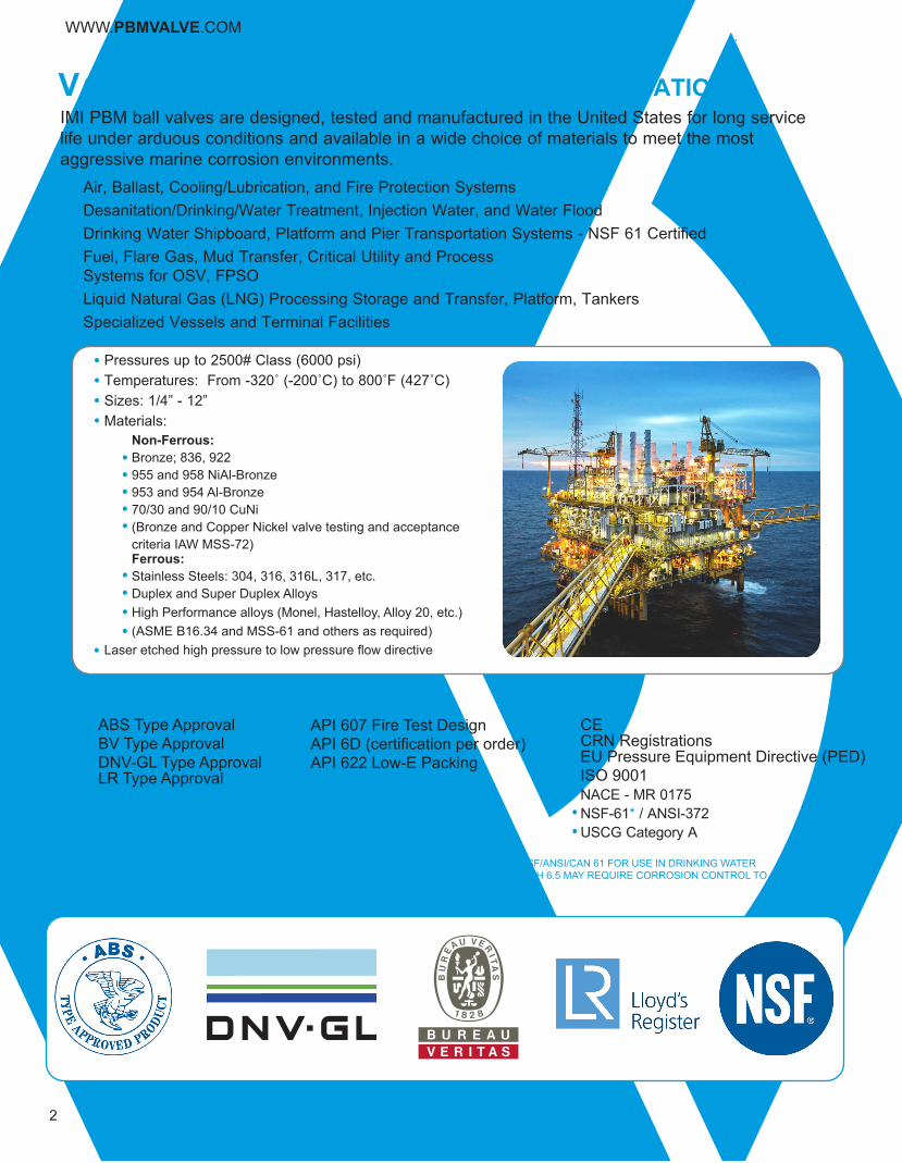
ValVes For Marine and oFFshore applicationsIMI PBM ball valves are designed, tested and manufactured in the United States for long service life under arduous conditions and available in a wide choice of materials to meet the most aggressive marine corrosion environments.
Air, Ballast, Cooling/Lubrication, and Fire Protection SystemsDesanitation/Drinking/Water Treatment, Injection Water, and Water FloodDrinking Water Shipboard, Platform and Pier Transportation Systems - NSF 61 CertifiedFuel, Flare Gas, Mud Transfer, Critical Utility and Process Systems for OSV, FPSOLiquid Natural Gas (LNG) Processing Storage and Transfer, Platform, TankersSpecialized Vessels and Terminal Facilities
2
WWW.PBMVALVE.COM
* COPPER ALLOYS C89833, C8935, AND C87600 HAVE BEEN EVALUATED BY NSF TO NSF/ANSI/CAN 61 FOR USE IN DRINKING WATER SUPPLIES PH OF 6.5 AND ABOVE. DRINKING WATER SUPPLIES THAT ARE LESS THAN PH 6.5 MAY REQUIRE CORROSION CONTROL TO LIMIT LEACHING OF COPPER INTO THE DRINKING WATER
VERI_1101664_COUV_FI_A4_GB.indd 1 4/02/11 15:40:22
ABS Type ApprovalBV Type ApprovalDNV-GL Type ApprovalLR Type Approval
APPROVALS:CECRN RegistrationsEU Pressure Equipment Directive (PED)ISO 9001NACE - MR 0175NSF-61* / ANSI-372USCG Category A
API 607 Fire Test DesignAPI 6D (certification per order)API 622 Low-E Packing
Pressures up to 2500# Class (6000 psi)Temperatures: From -320˚ (-200˚C) to 800˚F (427˚C)Sizes: 1/4” - 12”Materials:
Non-Ferrous:Bronze; 836, 922955 and 958 NiAl-Bronze 953 and 954 Al-Bronze70/30 and 90/10 CuNi(Bronze and Copper Nickel valve testing and acceptance criteria IAW MSS-72)Ferrous:Stainless Steels: 304, 316, 316L, 317, etc.Duplex and Super Duplex AlloysHigh Performance alloys (Monel, Hastelloy, Alloy 20, etc.)(ASME B16.34 and MSS-61 and others as required)
Laser etched high pressure to low pressure flow directive
3FIRE TESTED TO API-607
THERMAL EXPANSIONIndependent bolting for each valve end connection ensures consistent sealing throughout thermal cycles.
ENERGIZED SEAT BACK GASKETSStandard Iconel energized seat back gaskets enhance sealing throughout temperature fluctuations.
LIVE LOADED STEM PACKINGSRobust live loaded stem packing ensures reliable positive seal engagement throughout operating the thermal cycle and pressure range.
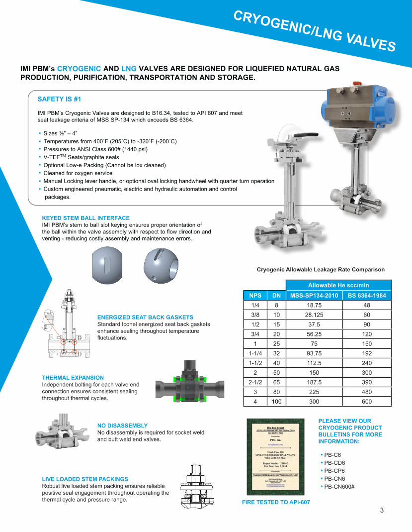
KEYED STEM BALL INTERFACEIMI PBM’s stem to ball slot keying ensures proper orientation of the ball within the valve assembly with respect to flow direction and venting - reducing costly assembly and maintenance errors.
IMI PBM’s CRYOGENIC AND LNG VALVES ARE DESIGNED FOR LIQUEFIED NATURAL GAS PRODUCTION, PURIFICATION, TRANSPORTATION AND STORAGE.
Allowable He scc/minNPS DN MSS-SP134-2010 BS 6364-19841/4 8 18.75 483/8 10 28.125 601/2 15 37.5 903/4 20 56.25 1201 25 75 150
1-1/4 32 93.75 1921-1/2 40 112.5 240
2 50 150 3002-1/2 65 187.5 390
3 80 225 4804 100 300 600
Cryogenic Allowable Leakage Rate Comparison
CRYOGENIC/LNG VALVES
SAFETY IS #1
IMI PBM’s Cryogenic Valves are designed to B16.34, tested to API 607 and meetseat leakage criteria of MSS SP-134 which exceeds BS 6364.
Sizes ½” – 4”Temperatures from 400˚F (205˚C) to -320˚F (-200˚C)Pressures to ANSI Class 600# (1440 psi)V-TEFTM Seats/graphite sealsOptional Low-e Packing (Cannot be lox cleaned)Cleaned for oxygen serviceManual Locking lever handle, or optional oval locking handwheel with quarter turn operationCustom engineered pneumatic, electric and hydraulic automation and control packages.
PLEASE VIEW OUR CRYOGENIC PRODUCT BULLETINS FOR MORE INFORMATION:
PB-C6PB-CD6PB-CP6PB-CN6PB-CN600#
NO DISASSEMBLYNo disassembly is required for socket weld and butt weld end valves.

4
F
E
D
B
A
G
an series 1, 150# class Manual diMensions AN Series seawater valves are 2-piece valves with two flanged end fittings and meet ANSI B16.10 long pattern face to face dimensions. In addition, encapsulated seats facilitate performance in high-velocity applications and support the seats in elevated temperature applications.
notes:1. Standard product is 316 Stainless Steel. Carbon Steel, Bronze and other materials are available upon request. Consult PBM.2. Dimensions meet ASME Standard B16.10 long pattern.3. Stainless Steel valves and Carbon Steel valves have raised face flanges, but are also available with flat faced flanges. Bronze valves have flat face flanges only.4. Drawings are for illustration purposes only. Consult PBM prior to any fabrication or installation work.5. A gear operator is recommended for valves 6” and larger. Consult PBM.6. Dimensions are for ANSI 150# Class valves. Consult PBM for 300# Class.
AN Series 1 Actuated Dimensions
Valve SizePort Dia.
A B D E F GApprox. Weight
(lbs.)Overall Length CL to Face EndCL to Bottom of
FlangeCL to top of
HandleHandle Length
from CLFlange
Dia.in mm in mm in mm in mm in mm in mm in mm lb kg
1/2” DN15 0.62 15.7 4.25 108.0 1.84 46.7 1.62 41.1 3.07 78.0 6.09 154.7 3.50 88.9 6 2.7
3/4” DN20 0.81 20.6 4.62 117.3 2.01 51.1 1.88 47.8 3.14 79.8 6.09 154.7 3.88 98.6 9 4.1
1” DN25 1.00 25.4 5.00 127.0 2.20 55.9 2.06 52.3 3.80 96.5 6.09 154.7 4.25 108.0 10 4.5
1-1/2” DN40 1.50 38.1 6.50 165.1 2.78 70.6 2.38 60.5 5.25 133.4 8.06 204.7 5.00 127.0 20 9.1
2” DN50 2.00 50.8 7.00 177.8 2.99 75.9 2.88 73.2 5.56 141.2 8.06 204.7 6.00 152.4 24 10.9
3” DN80 3.00 76.2 8.00 203.2 3.62 91.9 3.75 95.3 7.08 179.8 12.06 306.3 7.50 190.5 55 24.9
4” DN100 4.00 101.6 9.00 228.6 3.84 97.5 4.50 114.3 9.16 232.7 14.06 357.1 9.00 228.6 100 45.4
6” DN150 6.07 154.2 15.50 393.7 7.33 186.2 6.98 177.3 CF5 CF5 CF5 CF5 11.00 279.4 310 140.6
L
A
JK
C
L
H
WWW.PBMVALVE.COM
B
RTFE OR UHMWPE SEAT MATERIAL
Size ActuatorAir Pressure C H J K L
psig barg in mm in mm in mm in mm NPT
1/2” DN15Double Acting 60, 80 4.1/5.5 6.30 160.1 5.55 141.0 2.80 71.1 1.61 40.9 1/8Spring Return 60, 80 4.1/5.5 6.75 171.6 6.46 164.1 3.17 80.5 1.77 45.0 1/8
3/4” DN20
Double Acting 60, 80 4.1/5.5 6.41 162.8 5.55 141.0 2.80 71.1 1.61 40.9 1/8Spring Return 80 5.5 6.86 174.2 6.46 164.1 3.17 80.5 1.77 45.0 1/8Spring Return 60 4.1 7.57 192.3 8.27 210.1 3.72 94.5 2.07 52.6 1/8
1” DN25
Double Acting 60, 80 4.1/5.5 7.64 194.1 5.55 141.0 2.80 71.1 1.61 40.9 1/8Spring Return 80 5.5 8.80 223.5 8.27 210.1 3.72 94.5 2.07 52.6 1/8Spring Return 60 4.1 9.35 237.5 9.47 240.5 4.17 105.9 2.30 58.4 1/8
1-1/2” DN40
Double Acting 60, 80 4.1/5.5 8.97 227.9 8.27 210.1 3.72 94.5 2.07 52.6 1/8Spring Return 80 5.5 10.02 254.6 10.83 275.1 4.84 122.9 2.68 68.1 1/4Spring Return 60 4.1 11.38 289.1 13.11 333.0 5.39 136.9 2.87 72.9 1/4
2” DN50
Double Acting 60, 80 4.1/5.5 9.28 235.7 8.27 210.1 3.72 94.5 2.07 52.6 1/8Spring Return 80 5.5 10.33 262.3 10.83 275.1 4.84 122.9 2.68 68.1 1/4Spring Return 60 4.1 11.69 296.9 13.11 333.0 5.39 136.9 2.87 72.9 1/4
3” DN80
Double Acting 60, 80 4.1/5.5 12.13 308.1 13.11 333.0 5.39 136.9 2.87 72.9 1/4Spring Return 80 5.5 12.61 320.3 14.65 372.1 5.83 148.1 3.15 80.0 1/4Spring Return 60 4.1 13.50 342.9 17.13 435.1 6.46 164.1 3.44 87.4 1/4
4” DN100
Double Acting 80 5.5 17.26 438.4 13.11 333.0 5.39 136.9 2.87 72.9 1/4Double Acting 60 4.1 17.74 450.6 14.65 372.1 5.83 148.1 3.15 80.0 1/4Spring Return 80 5.5 19.57 497.1 19.69 500.1 7.32 185.9 3.90 99.1 1/4Spring Return 60 4.1 21.82 554.2 22.78 578.6 8.54 216.9 4.29 109.0 1/4
6” DN150
Double Acting 60, 80 4.1/5.5 21.54 547.1 19.69 500.1 7.32 185.9 3.90 99.1 1/4Spring Return 80 5.5 23.79 604.3 22.78 578.6 8.54 216.9 4.29 109.0 1/4Spring Return 60 4.1 28.55 725.2 26.46 672.1 11.42 290.1 5.71 145.0 1/4

5
IMI Critical EngineeringIMI PBM
an series 5, (stainless and carbon)AN Series seawater valves are 2-piece valves with two flanged end fittings and meet ANSI B16.10 long pattern face to face dimensions. In addition, encapsulated seats facilitate performance in high-velocity applications and support the seats in elevated temperature applications.
Size Units Port Dia.
A B C D E J Ext. Locking Handle Locking Handle
Overall Length CL to End Flange Dia. CL to Top of Handle
Handle Length from CL
CL to bottomF G H K Hole Dia.
for Lock150# 300# 150# 300# 150# 300# 150# 300#
1/2” DN15 inch 0.50 4.25 5.50 1.85 2.52 3.50 3.75 2.66 4.15 1.62 1.75 7.19 1.00 5.09 1.62 0.25mm 12.7 108.0 139.7 47.0 64.0 88.9 95.3 67.6 105.4 41.1 44.5 182.6 25.4 129.3 41.1 6.4
3/4” DN20 inch 0.75 4.62 6.00 2.12 2.90 3.88 4.62 2.78 4.15 1.80 2.15 7.34 1.00 5.09 1.62 0.25mm 19.1 117.3 152.4 53.8 73.7 98.6 117.3 70.6 105.4 45.7 54.6 186.4 25.4 129.3 41.1 6.4
1” DN25 inch 1.00 5.00 6.50 2.25 3.15 4.25 4.88 3.09 5.06 2.06 2.38 7.63 1.00 5.09 2.08 0.28mm 25.4 127.0 165.1 57.2 80.0 108.0 124.0 78.5 128.5 52.3 60.5 193.8 25.4 129.3 52.8 7.1
1-1/2” DN40 inch 1.50 6.50 7.50 2.68 3.18 5.00 6.12 4.16 8.03 2.38 3.00 9.50 1.31 8.00 2.58 0.38mm 38.1 165.1 190.5 68.1 80.8 127.0 155.4 105.7 204.0 60.5 76.2 241.3 33.3 203.2 65.5 9.7
2” DN50 inch 2.00 7.00 8.50 3.12 3.84 6.00 6.50 4.46 8.03 2.88 3.12 9.81 1.31 8.00 2.58 0.38mm 50.8 177.8 215.9 79.2 97.5 152.4 165.1 113.3 204.0 73.2 79.2 249.2 33.3 203.2 65.5 9.7
3” DN80 inch 3.00 8.00 11.12 3.57 5.19 7.50 8.25 7.00 12.06 3.50 4.00 11.69 1.50 12.06 3.47 0.38mm 76.2 203.2 282.4 90.7 131.8 190.5 209.6 177.8 306.3 88.9 101.6 296.9 38.1 306.3 88.1 9.7
4” DN100 inch 4.00 9.00 12.00 3.84 5.34 9.00 10.00 7.39 24.06 4.38 4.75 13.03 3.50 24.06 NA NAmm 101.6 228.6 304.8 97.5 135.6 228.6 254.0 187.7 611.1 111.3 120.7 331.0 88.9 611.1 NA NA
Size Units Port Dia.
A B C J S T U V
Overall Length CL to End Flange Dia. CL to bottom Body Width CL to Top of Gear
Op
Handwheel Dia.
OAL Width
150# 300# 150# 300# 150# 300# 150# 300# 150# 300# 150# 300#
6” DN150 inch 6.00 15.50 15.88 7.33 7.70 11.00 12.50 6.75 7.72 13.50 15.53 16.32 12.00 16.28 17.25mm 152.4 393.7 403.4 186.2 195.6 279.4 317.5 171.5 196.1 342.9 394.5 414.5 304.8 413.5 438.2
8” DN200 inch 8.00 18.00 19.75 8.56 9.51 13.50 15.00 8.37 9.38 17.72 18.75 CF CF CF CFmm 203.2 457.2 501.7 217.4 241.6 342.9 381.0 212.6 238.3 450.1 476.3 CF CF CF CF
10” DN250 inch 10.00 21.00 22.38 10.07 CF 16.00 17.50 10.75 CF 21.50 CF CF CF CF CFmm 254.0 533.4 568.5 255.8 CF 406.4 444.5 273.1 CF 546.1 CF CF CF CF CF
12” DN300 inch 12.00 24.00 25.50 12.00 CF 19.00 20.50 12.00 CF 24.00 CF CF CF CF CFmm 304.8 609.6 647.7 304.8 CF 482.6 520.7 304.8 CF 609.6 CF CF CF CF CF
tn series 5 150# class (bronze, aluMinuM bronze, stainless, duplex and carbon)TN adds a trunnion to an AN Series valve.
ANSI Valve with Gear OperatorANSI Valve with Locking Handle ANSI Valve with Ext. Locking Handle
G
F
H
J
A
Port
U
B
K
C
E
A
D
B
VJ
T
J
S
AN SeriesBronze ANSI Prepped for
Actuation
AN SeriesStainless ANSI Valve
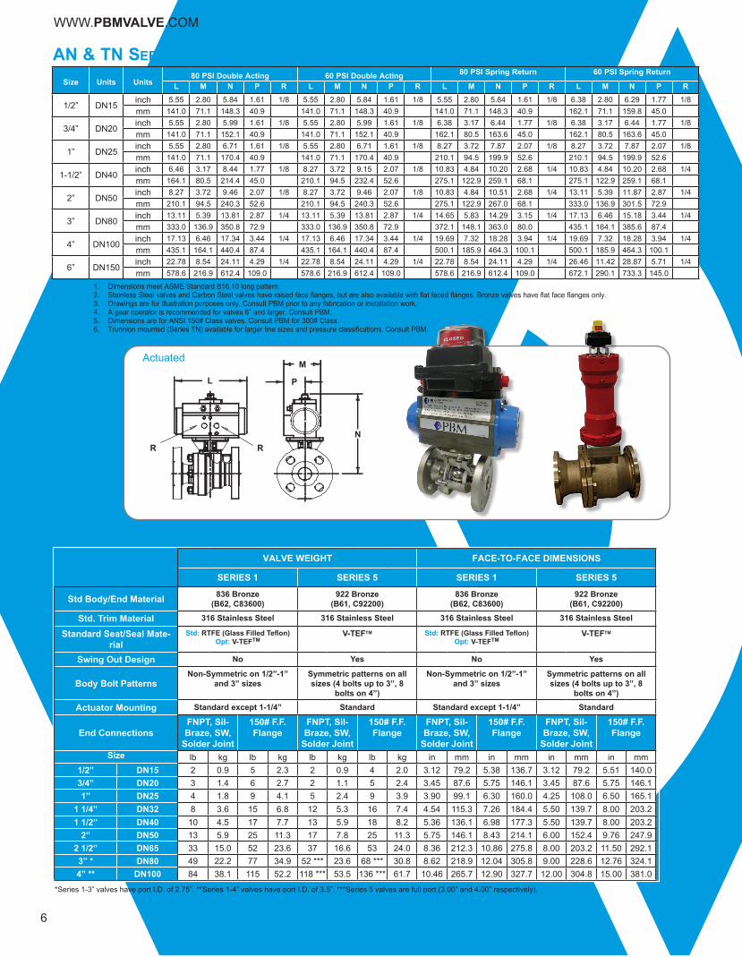
Size Units Units80 PSI Double Acting 60 PSI Double Acting 80 PSI Spring Return 60 PSI Spring Return
L M N P R L M N P R L M N P R L M N P R
1/2” DN15inch 5.55 2.80 5.84 1.61 1/8 5.55 2.80 5.84 1.61 1/8 5.55 2.80 5.84 1.61 1/8 6.38 2.80 6.29 1.77 1/8mm 141.0 71.1 148.3 40.9 141.0 71.1 148.3 40.9 141.0 71.1 148.3 40.9 162.1 71.1 159.8 45.0
3/4” DN20inch 5.55 2.80 5.99 1.61 1/8 5.55 2.80 5.99 1.61 1/8 6.38 3.17 6.44 1.77 1/8 6.38 3.17 6.44 1.77 1/8mm 141.0 71.1 152.1 40.9 141.0 71.1 152.1 40.9 162.1 80.5 163.6 45.0 162.1 80.5 163.6 45.0
1” DN25inch 5.55 2.80 6.71 1.61 1/8 5.55 2.80 6.71 1.61 1/8 8.27 3.72 7.87 2.07 1/8 8.27 3.72 7.87 2.07 1/8mm 141.0 71.1 170.4 40.9 141.0 71.1 170.4 40.9 210.1 94.5 199.9 52.6 210.1 94.5 199.9 52.6
1-1/2” DN40inch 6.46 3.17 8.44 1.77 1/8 8.27 3.72 9.15 2.07 1/8 10.83 4.84 10.20 2.68 1/4 10.83 4.84 10.20 2.68 1/4mm 164.1 80.5 214.4 45.0 210.1 94.5 232.4 52.6 275.1 122.9 259.1 68.1 275.1 122.9 259.1 68.1
2” DN50inch 8.27 3.72 9.46 2.07 1/8 8.27 3.72 9.46 2.07 1/8 10.83 4.84 10.51 2.68 1/4 13.11 5.39 11.87 2.87 1/4mm 210.1 94.5 240.3 52.6 210.1 94.5 240.3 52.6 275.1 122.9 267.0 68.1 333.0 136.9 301.5 72.9
3” DN80inch 13.11 5.39 13.81 2.87 1/4 13.11 5.39 13.81 2.87 1/4 14.65 5.83 14.29 3.15 1/4 17.13 6.46 15.18 3.44 1/4mm 333.0 136.9 350.8 72.9 333.0 136.9 350.8 72.9 372.1 148.1 363.0 80.0 435.1 164.1 385.6 87.4
4” DN100inch 17.13 6.46 17.34 3.44 1/4 17.13 6.46 17.34 3.44 1/4 19.69 7.32 18.28 3.94 1/4 19.69 7.32 18.28 3.94 1/4mm 435.1 164.1 440.4 87.4 435.1 164.1 440.4 87.4 500.1 185.9 464.3 100.1 500.1 185.9 464.3 100.1
6” DN150inch 22.78 8.54 24.11 4.29 1/4 22.78 8.54 24.11 4.29 1/4 22.78 8.54 24.11 4.29 1/4 26.46 11.42 28.87 5.71 1/4mm 578.6 216.9 612.4 109.0 578.6 216.9 612.4 109.0 578.6 216.9 612.4 109.0 672.1 290.1 733.3 145.0
1. Dimensions meet ASME Standard B16.10 long pattern.2. Stainless Steel valves and Carbon Steel valves have raised face flanges, but are also available with flat faced flanges. Bronze valves have flat face flanges only.3. Drawings are for illustration purposes only. Consult PBM prior to any fabrication or installation work.4. A gear operator is recommended for valves 6” and larger. Consult PBM.5. Dimensions are for ANSI 150# Class valves. Consult PBM for 300# Class.6. Trunnion mounted (Series TN) available for larger line sizes and pressure classifications. Consult PBM.
an & tn series 5 actuated
6
NOTES:
WWW.PBMVALVE.COM
VALVE WEIGHT FACE-TO-FACE DIMENSIONS
SERIES 1 SERIES 5 SERIES 1 SERIES 5
Std Body/End Material 836 Bronze(B62, C83600)
922 Bronze(B61, C92200)
836 Bronze(B62, C83600)
922 Bronze(B61, C92200)
Std. Trim Material 316 Stainless Steel 316 Stainless Steel 316 Stainless Steel 316 Stainless Steel
Standard Seat/Seal Mate-rial
Std: RTFE (Glass Filled Teflon)Opt: V-TEFTM
V-TEFTM Std: RTFE (Glass Filled Teflon)Opt: V-TEFTM
V-TEFTM
Swing Out Design No Yes No Yes
Body Bolt PatternsNon-Symmetric on 1/2”-1”
and 3” sizesSymmetric patterns on all sizes (4 bolts up to 3”, 8
bolts on 4”)
Non-Symmetric on 1/2”-1” and 3” sizes
Symmetric patterns on all sizes (4 bolts up to 3”, 8
bolts on 4”)
Actuator Mounting Standard except 1-1/4” Standard Standard except 1-1/4” Standard
End ConnectionsFNPT, Sil-Braze, SW,
Solder Joint
150# F.F. Flange
FNPT, Sil-Braze, SW,
Solder Joint
150# F.F. Flange
FNPT, Sil-Braze, SW,
Solder Joint
150# F.F. Flange
FNPT, Sil-Braze, SW,
Solder Joint
150# F.F. Flange
Size lb kg lb kg lb kg lb kg in mm in mm in mm in mm1/2” DN15 2 0.9 5 2.3 2 0.9 4 2.0 3.12 79.2 5.38 136.7 3.12 79.2 5.51 140.03/4” DN20 3 1.4 6 2.7 2 1.1 5 2.4 3.45 87.6 5.75 146.1 3.45 87.6 5.75 146.11” DN25 4 1.8 9 4.1 5 2.4 9 3.9 3.90 99.1 6.30 160.0 4.25 108.0 6.50 165.1
1 1/4” DN32 8 3.6 15 6.8 12 5.3 16 7.4 4.54 115.3 7.26 184.4 5.50 139.7 8.00 203.21 1/2” DN40 10 4.5 17 7.7 13 5.9 18 8.2 5.36 136.1 6.98 177.3 5.50 139.7 8.00 203.2
2” DN50 13 5.9 25 11.3 17 7.8 25 11.3 5.75 146.1 8.43 214.1 6.00 152.4 9.76 247.92 1/2” DN65 33 15.0 52 23.6 37 16.6 53 24.0 8.36 212.3 10.86 275.8 8.00 203.2 11.50 292.13” * DN80 49 22.2 77 34.9 52 *** 23.6 68 *** 30.8 8.62 218.9 12.04 305.8 9.00 228.6 12.76 324.14” ** DN100 84 38.1 115 52.2 118 *** 53.5 136 *** 61.7 10.46 265.7 12.90 327.7 12.00 304.8 15.00 381.0
bronze 2-Way sp series ValVe coMparison
*Series 1-3” valves have port I.D. of 2.75”. **Series 1-4” valves have port I.D. of 3.5”. ***Series 5 valves are full port (3.00” and 4.00” respectively).
N
L P
M
R R
Actuated

7
IMI Critical EngineeringIMI PBM
A
sp series 1 (836 bronze) SP Series 1 seawater valves are 3-piece valves available in female NPT, socket-weld (for pipe), sil-braze (for pipe) and 150# flanged end fittings.
SizePort
Diameter
A B C D EApprox. Wgt.
Face to Face CL to Face HandleLengthfrom CL
CL to
Top ofHandle
CL to Bottom
Q- S- T- U- L- Q- S-
T- U- L- Q- S- T- U- L- Q- S-
T- U- L-
inch mm inch mm inch mm inch mm inch mm inches mm inch mm inch mm inch mm lb kg lb kg
1/4” DN8 0.62 15.7 3.12 79.2 - - 1.56 39.6 - - 6.09 154.7 3.03 77.0 1.34 34.0 - - 2 0.9 - -
3/8” DN10 0.62 15.7 3.12 79.2 - - 1.56 39.6 - - 6.09 154.7 3.03 77.0 1.34 34.0 - - 2 0.9 - -
1/2” DN15 0.62 15.7 3.12 79.2 5.38 136.7 1.56 39.6 2.69 68.3 6.09 154.7 3.03 77.0 1.34 34.0 1.75 44.5 2 0.9 5 2.3
3/4” DN20 0.81 20.6 3.45 87.6 5.75 146.1 1.72 43.7 2.88 73.2 6.09 154.7 3.15 80.0 1.47 37.3 1.94 49.3 3 1.4 6 2.7
1” DN25 1.00 25.4 3.90 99.1 6.30 160.0 1.95 49.5 3.15 80.0 6.09 154.7 3.53 89.7 1.69 42.9 2.13 54.1 4 1.8 9 4.1
1-1/4” DN32 1.25 31.8 4.54 115.3 7.26 184.4 2.27 57.7 3.63 92.2 8.06 204.7 4.90 124.5 1.57 39.9 2.31 58.7 8 3.6 15 6.8
1-1/2” DN40 1.50 38.1 5.36 136.1 6.98 177.3 2.68 68.1 3.49 88.6 8.06 204.7 5.08 129.0 1.71 43.4 2.50 63.5 10 4.5 17 7.7
2” DN50 2.00 50.8 5.75 146.1 8.43 214.1 2.87 72.9 4.21 106.9 8.06 204.7 5.45 138.4 2.03 51.6 3.00 76.2 13 5.9 25 11.3
2-1/2” DN65 2.50 63.5 8.36 212.3 10.86 275.8 4.18 106.9 5.42 137.7 12.06 306.3 5.50 139.7 2.81 71.4 3.50 88.9 33 15.0 52 23.6
3” DN80 2.75 69.9 8.62 218.9 12.04 305.8 4.31 109.5 6.02 152.9 12.06 306.3 6.82 173.2 3.88 98.6 3.88 98.6 49 22.2 77 34.9
4” DN100 3.50 88.9 10.46 265.7 12.90 327.7 5.23 132.8 6.45 163.8 12.06 306.3 7.32 185.9 4.50 114.3 4.50 114.3 84 38.1 115 52.2
1. SP Series valves with 150# flanges are 3-piece valves that do not meet ANSI face to face dimensions. Use AN Series 2-piece flanged valves if ANSI face to face dimensions are required. 2. Consult PBM for actuator mounting dimensions.3. For flanged valves, flange holes straddle the center line except for the SP Series 1, 1-1/2” valves.
B
C
150# FlangeL-
D
E
NOTES:
sp series 5 (922 bronze)
SizePort
Diameter
A B C D EApprox. Wgt.
Face to Face CL to Face HandleLengthfrom CL
CL to
Top ofHandle
CL to Bottom
Q- S- T- U- L- Q- S-
T- U- L- Q- S- T- U- L- Q- S-
T- U- L-
inch mm inch mm inch mm inch mm inch mm inch mm inch mm inch mm inch mm lb kg lb kg
1/2” DN15 0.50 12.7 3.12 79.2 5.51 140.0 1.56 39.6 2.76 70.1 4.15 105.4 2.63 66.8 0.92 23.4 1.75 44.5 2 0.9 4 2.0
3/4” DN20 0.75 19.1 3.45 87.6 5.75 146.1 1.73 43.9 2.88 73.2 4.15 105.4 2.79 70.9 1.00 25.4 1.94 49.3 2 1.1 5 2.4
1” DN25 1.00 25.4 4.25 108.0 6.50 165.1 2.13 54.1 3.25 82.6 5.09 129.3 3.06 77.7 1.33 33.8 2.13 54.1 5 2.4 9 3.9
1-1/4” DN32 1.37 34.8 5.50 139.7 8.00 203.2 2.75 69.9 4.00 101.6 8.03 204.0 4.38 111.3 1.78 45.2 2.32 58.9 12 5.3 16 7.4
1-1/2” DN40 1.50 38.1 5.50 139.7 8.00 203.2 2.75 69.9 4.00 101.6 8.03 204.0 4.38 111.3 1.78 45.2 2.50 63.5 13 5.9 18 8.2
2” DN50 2.00 50.8 6.00 152.4 9.76 247.9 3.00 76.2 4.88 124.0 8.06 204.7 4.69 119.1 2.15 54.6 3.00 76.2 17 7.8 25 11.3
2-1/2” DN65 2.50 63.5 8.00 203.2 11.50 292.1 4.00 101.6 5.75 146.1 12.06 306.3 6.51 165.4 2.79 70.9 3.50 88.9 37 16.6 53 24.0
3” DN80 3.00 76.2 9.00 228.6 12.76 324.1 4.50 114.3 6.38 162.1 12.06 306.3 6.85 174.0 3.14 79.8 3.75 95.3 52 23.6 68 30.8
4” DN100 4.00 101.6 12.00 304.8 15.00 381.0 6.00 152.4 7.50 190.5 24.06 611.1 9.0 228.6 4.91 124.7 4.91 124.7 118 53.5 136 61.7
NPTQ- S-
SP SeriesBronze 2-Way Flanged Valve
SP SeriesBronze 3-Piece Valve
Solder JointT-
Socket WeldU-

8
ValveSize
B C D G E F
150#FlangeDiam.
ApproximateWeightBall
PortFace-to-Face CL to End CL to Bottom or Side Handle
Lengthfrom CL
CL toTop ofHandleQ-
S-U-
L-Q-S-U-
L- Q-S-U-
L-Q-S-U-
L-
Size inch mm inch mm inch mm inch mm inch mm inch mm inch mm inches mm inch mm inch mm lb kg lb kg
1/2” DN15 0.62 15.7 3.12 79.2 - - 1.56 39.6 - - 2.50 63.5 - - 6.09 154.7 3.03 77.0 3.50 88.9 2 0.9 - -
3/4” DN20 0.81 20.6 3.77 95.8 - - 1.89 48.0 - - 2.50 63.5 - - 6.09 154.7 3.03 77.0 2.38 60.5 3 1.4 - -
1” DN25 1.00 25.4 3.90 99.1 6.28 159.5 1.95 49.5 3.14 79.8 2.44 62.0 3.16 80.3 6.09 154.7 3.53 89.7 4.25 108.0 5 2.3 10 4.5
1-1/2” DN40 1.50 38.1 5.36 136.1 7.00 177.8 2.68 68.1 3.50 88.9 3.38 85.9 3.50 88.9 8.06 204.7 5.05 128.3 5.00 127.0 12 5.4 23 10.4
2” DN50 2.00 50.8 5.75 146.1 8.40 213.4 2.86 72.6 4.20 106.7 3.25 82.6 4.20 106.7 8.06 204.7 5.42 137.7 6.00 152.4 15 6.8 30 13.6
3” DN80 2.75 69.9 8.62 218.9 11.87 301.5 4.31 109.5 5.93 150.6 5.12 130.0 6.00 152.4 12.44 316.0 6.82 173.2 7.50 190.5 49 22.2 93 42.2
4” DN100 3.50 88.9 - - 12.91 327.9 - - 6.45 163.8 - - 6.44 163.6 12.44 316.0 7.21 183.1 9.00 228.6 - - 120 54.4
dp series 1 diMensional data (836 bronze)Diverter Port Valves with Female NPT (Q-), Sil-Braze (S-), Socket weld (U-) and 150# Flanged (L-) End Fittings
notes:1. Male NPT, Solder Joint, Camlock and Grooved end fittings are also available.2. Other flanged end fittings are available upon request.3. 1/2” through 1” valves have 3 bolts, 3/4” valves have 4 bolts, 1-1/4” through 2” valves have 4 bolts, 3” through 4” valves have 8 bolts.4. Flange holes straddle the centerline except for Series 1, 1-1/2” size.5. Drawings are for illustration purposes only. Consult PBM prior to any fabrication or installation work.6. Using a welded connection on the common port of a DP or MP valve may complicate maintenance. Provisions must be made to allow removal of end fittings and body from the line.
Socket Weld
U-
S-NPTQ-
Size
B C D, G E F ApproximateWeightBall
PortFace-to-Face CL to Face
HandleLengthfrom CL
CL toTop ofHandle
Q-S-U-
L-Q-S-U-
L-Q-S-U-
L-
inch mm inch mm inch mm inches mm inch mm inch mm inch mm lb kg lb kg1/2” DN15 0.62 15.7 4.00 101.6 - - 2.00 50.8 - - 6.09 154.7 3.83 97.3 8 3.6 - -
3/4” DN20 0.75 19.1 4.00 101.6 - - 2.00 50.8 - - 6.09 154.7 3.83 97.3 12 5.4 - -
1” DN25 1.00 25.4 4.72 119.9 7.24 183.9 2.36 59.9 3.62 91.9 8.06 204.7 4.99 126.7 12 5.4 19 8.6
1-1/2” DN40 1.50 38.1 6.56 166.6 10.56 268.2 3.28 83.3 5.28 134.1 12.44 316.0 5.42 137.7 33 15.0 46 20.9
2” DN50 2.00 50.8 7.76 197.1 11.94 303.3 3.88 98.6 5.97 151.6 12.06 306.3 5.86 148.8 52 23.6 72 32.7
3” DN80 2.75 69.9 11.06 280.9 14.56 369.8 5.53 140.5 7.28 184.9 12.06 306.3 6.82 173.2 81 36.7 119 54.0
4” DN100 3.00 76.2 - - 17.00 431.8 - - 8.50 215.9 14.06 357.1 8.75 222.3 - - 250 113.4
E
D C A
G
F
A
G
B
Mp series 1 diMensional data (836 bronze)Multi-Port Valves with Female NPT (Q-), Sil-Braze (S-), Socket weld (U-) and 150# Flanged (L-) End Fittings
MP SeriesBronze 3-Way Flanged Valve
DP Series Bronze Diverter Port
Valve
WWW.PBMVALVE.COM

9
torQue charts
Allowable Working Pressures and Temperatures ValveStyle/Series Material Size (inches)
Non-Flanged-20 to 100˚F
-28.9 to 37.8˚C 300˚F 148.9˚C 450˚F 232.2˚C
psig barg psig barg psig barg
SP, DPSeries 5
316 SS/316L 1-1/2” (DN40) and smaller 900 62.1 770 53.1 680 46.9316 SS/316L 2” and larger 720 49.6 620 42.7 540 37.2
C-276 All 600 41.4 520 35.9 450 31.0Carbon Stl. 1-1/2” (DN40) and smaller 900 62.1 770 53.1 680 46.9Carbon Stl. 2” (DN50) and larger 740 51.0 655 45.2 620 42.7
SP, DPSeries 1
316 SS/316L 1-1/2” (DN40) and smaller 900 62.1 770 53.1 680 46.9316 SS/316L 2” (DN50) 575 39.6 490 33.8 430 29.6316 SS/316L 3” (DN80) & 4” (DN100) 850 58.6 720 49.6 640 44.1
836/922/L.F. Bronze 1-1/2” (DN40) and smaller 400 27.6 310 21.4 220 15.2836/922/L.F. Bronze 2” (DN50) 300 20.7 230 15.9 160 11.0836/922/L.F. Bronze 3” (DN80) & 4” (DN100) 350 24.1 270 18.6 190 13.1
SP Series 6
316 SS/316L 3” (DN80) and smaller 720 49.6 620 42.7 540 37.2Carbon Stl. 3” (DN80) and smaller 740 51.0 655 45.2 620 42.7
AN, CNAll
Series
316 SS/316L All
See Flanged Table at Right.C-276 AllCarbon Steel All
Bronze All
CP Series 6
316 SS/316L All 720 49.6 620 42.7 540 37.2C-276 All 600 41.4 520 35.9 450 31.0
922 Bronze All 600 41.4 600 41.4 580 40.0
MPSeries 1
836/922/L.F Bronze 1-1/2” (DN40 and smaller) 400 27.6 310 21.4 220 15.2836/922/L.F Bronze 2” (DN50) 350 24.1 270 18.6 190 13.1836/922/L.F Bronze 3” (DN80) 300 20.7 230 15.9 160 11.0836/922/L.F Bronze 4” (DN100) See Flanged Table at Right
Ductile Iron 1-1/2” (DN40) 550 37.9 470 32.4 400 27.6Ductile Iron 2” (DN50) 500 34.5 430 29.6 370 25.5Ductile Iron 3” (DN80) 450 31.0 380 26.2 330 22.8Ductile Iron 4” (DN100) See Flanged Table at Right
Valid for all flanged valves:ANSI 150# FLANGE
ValveMaterial
-20° to 100° F
-28° to 38° C
300° F
150° C
450° F
232° C
psig barg psig barg psig barg
836 Bronze 225 15.5 180 12.4 135 9.3
Lead-Free Bronze 225 15.5 180 12.4 135 9.3
922 Bronze 225 15.5 195 13.4 160 11.0
955 Bronze 225 15.5 195 13.4 160 11.0
C-276 230 15.9 200 13.8 180 12.4
316/316L S/S 275 19.0 215 14.8 180 12.4
Carbon Steel 285 19.7 230 15.9 185 12.8
Ductile Iron 250 17.2 215 14.8 185 12.8
ANSI 300# FLANGE
Valve Material
-20° to 100° F
-28° to 38° C
300° F
150° C
450° F
232° C
psig barg psig barg psig barg
C-276 600 41.4 520 35.9 475 32.8
316/316L S/S 720 49.6 560 38.6 495 34.1
Carbon Steel 740 51.0 655 45.2 620 42.7
IMI Critical EngineeringIMI PBM
Valve Style/Series
Valve Size (in.)
As Built Torque
Minimum Actuator Sizing vs. Differential Pressure Across Seats
0psig
0 barg
100psig
6.9barg
200psig
13.8 barg
300 psig
20.7 barg
400 psig
27.6barg
500 psig
34.5barg
600psig
41.4barg
700psig
48.3barg
in.-lb N-m in.-lb N-m in.-lb N-m in.-lb N-m in.-lb N-m in.-lb N-m in.-lb N-m in.-lb N-m in.-lb N-m
AllSeries5 & 62-Way
& 3-Way
1/2 32 3.6 64 7.2 64 7.2 64 7.2 64 7.2 64 7.2 64 7.2 64 7.2 64 7.23/4 40 4.5 80 9.0 80 9.0 80 9.0 80 9.0 80 9.0 96 10.8 112 10.8 128 12.71 58 6.6 116 13.1 116 13.1 116 13.1 150 16.9 185 20.9 220 24.9 trun.
1-1/2 154 17.4 308 34.8 308 34.8 440 49.7 580 65.5 715 80.8 trun. trun.2 182 20.6 364 41.1 364 41.1 635 71.7 910 102.8 1180 133.3 trun. trun.
2-1/2 288 32.5 576 65.1 576 65.1 1200 135.6 1600 180.8 trun.3 430 48.6 860 97.2 860 97.2 1560 176.3 trun. trun.4 787 88.9 1570 177.4 2650 2994 2650 299.4 trun. trun.6 1920 217.0 3840 433.9 7100 802.3 Use trunnion above 75 psid.
ANSeries1 & 3
1/2 38 4.3 76 8.6 76 8.6 76 8.6 76 8.63/4 48 5.4 96 10.8 96 10.8 96 10.8 96 10.81 58 6.6 116 13.1 116 13.1 116 13.1 150 16.9
1-1/2 154 17.4 308 34.8 308 34.8 440 49.7 580 65.52 182 20.6 365 41.2 365 41.2 635 71.7 910 102.83 430 48.6 860 97.2 860 97.2 1560 176.3 2050 231.64 787 88.9 1570 177.4 2650 299.4 4300 485.8 6000 677.96 1920 216.9 3840 433.9 7200 813.5 12000 1355.8 trun. trun.
CPSeries 6
These areactuals,
notsizing.
1/2 95 11 95 11 95 11 95 11 95 11 95 11 95 11 101 11 110 123/4 95 11 95 11 95 11 95 11 95 11 95 11 95 11 101 11 110 121 145 16 160 18 160 18 160 18 160 18 170 19 193 22 215 24 238 27
1-1/2 420 47 420 47 420 47 420 47 420 47 477 54 544 61 611 69 677 762 540 61 840 95 840 95 840 95 866 98 1013 114 1162 131 1310 148 1458 1653 1020 115 1320 149 1320 149 1542 174 1984 224 2425 274 2866 324 3307 374 3749 4244 Consult IMI PBM Engineering
MPSeries 1
1/2, 3/4 77 8.7 144 16.3 144 16.3 144 16.3 144 16.3 144 16.31 192 21.7 385 43.5 385 43.5 385 43.5 385 43.5 385 43.5
1-1/2 384 43.4 770 87 770 87 770 87 940 106.2 trun. trun2 432 48.8 865 97.7 865 97.7 865 97.7 1200 135.6 trun. trun.3 576 65.1 1150 129.9 1150 129.9 1620 183 2100 135.64 864 97.6 1700 192.1 3000 339 trun. trun.
SP, DPSeries 1
1/2 48 5 96 6.6 96 6.6 96 6.6 96 6.6 96 6.6 96 6.6 96 6.6 96 6.63/4 60 7 120 8.3 120 8.3 120 8.3 120 8.3 120 8.3 120 8.3 136 136 142 9.81 72 8.1 144 9.9 144 9.9 144 9.9 144 9.9 179 12.3 220 15.2 trun. trun.
1-1/2 168 19 336 23.2 336 23.2 440 30.3 580 40.0 715 49.3 trun.2 192 22 384 26.5 384 25.5 635 43.8 910 62.7 1180 81.4 trun.
2-1/2 300 34 600 41.4 600 41.4 1200 82.7 1600 110.3 trun.3 420 48 860 59.3 860 59.3 1560 107.6 trun.4 540 61 1080 74.5 2500 172.4 trun.

10
WWW.PBMVALVE.COM
1 2 3 4 5 6 7 8 9 10 11 12 13 14 15 16 17 18 19 20S P H L E 5 Q − G − − − 3 4 A − V X X X
AN ANSI A- A 4 B- F(9)CN Cryogenic (ANSI) C- Hastelloy® C-276 B 5 D- GCD Cryogenic 3-way C1 Hastelloy® B2 C 6 J- HCP Cryogenic D- Iron(6) D L- IC6 Cryogenic E- Carbon Steel(6) E M- JDP Diverter Port G- Lead Free Bronze F P- KMP Multi-Port H- 316/316L Stainless G Q- LSP Industrial 2-way HC Alloy 20 H Q1 M
HL 316L Stainless J S- Q(9)HF F316L Forged K T- YH2 317L Stainless L U- ZI- Inconel® 600 M -Z 0M- Monel 400 1N- 922 Bronze 2P- AL6XN 3R- 955 NiAl-Bronze 4S- 953 Al-Bronze 5T- Gr. 5 Titanium 9T2 Gr. 2 Titanium 3T7 Gr. 7 Titanium 4W- Nickel 200 5X- 958 NiAl-Bronze CGZ- 70/30 CuNi HT 71- 90/10 CuNi CT 95- Iconel® 625 TF9- 954 Al-Bronze VT25 254SMO®6Mo UT22 Duplex 2205 F76
EPVIVV
O-RINGMetal None
Ext. Sch 10 buttweld VI
SEAT
Part Number Position
Part Number Code Example
SEAT & SEAL/FILLERS/O-RINGS (IF USED) (4)(9)
END CONNECTION(3) (7-8)
INDUSTRIAL VALVESSIZE (5)
SERIES (6)
PRODUCT (1-2)
MATERIAL(2) (3-4)
3/41
1-1/2
150# Flange300# Flange
TF3/8
34
22-1/2
6
FILLER
BSPTSil-braze1 groove (pipe)
Ext. socket weld
Aluminum 1/4 Ext. Sch 40 buttweld
HT
TF
UTUT
UT
Series 4Series 5Series 61/2
For other end fittings, Consult Factory
Column 8 optionsNon Adjust-O-Seal®Reduced portNon Adjust-O-Seal® & Reduced port
No end fittings
S-TEF®
SEAT/SEAL/MATERIAL CODESCarbon-Graphite
Solder joint (tube)Socket weld (pipe)
EP
CG
TF
Male NPTFemale NPT
1-1/4
HTHT
CT
VIHT VT VI
VT VI
VT EP
UT VI
VT VIVI
NoneNoneEP
TF VT EPUTUTUTTF
VTUT EP
VV
EPEP
Flat-faced flangesBar-stockC-TEF™
V-TEF™VTFE (Cavity Fillers Only)UHMWPE
For other materials, Consult Factory
O-RING MATERIAL CODESEPRFKMFEP Encapsulated FKM
O-RINGS ARE NOT USED IN ALL VALVE PRODUCTS - SEE EACH RESPECTIVE
PAGE
Metal SeatsSuper Duplex 32760
VALVE CONFIGURATION ORDERING INFORMATIONNumber(s) in parentheses indicate valve configuration part number position
Page 2
- - - -● F 00 A
G 02 w/o handles, w/stem actr prep BI 03 CJ 04 DK 05 E
- - L 07 F02 M 08 G
N 09 H5 O 10 I6 P 11 K7 Q 12 L8 R 13 M9 S 14 N
10 T 17 O11 18 Q
U 71 SV 72
- 1A 2BC 24vdc 24vdc 24vdc 24vdc 24vdc -D 20 LE 21F 55 22 M
56 23 ZG 24H 57 25I 58 26J 27K 28L 59 29
60 30M 31N 61 32O 62 33P 34Q 35R 63 36
64 3738
65 39- 66 40A 41B 42C 67 43D 68 44E 45F 69 46G 70 47K Ball with vent hole (downstream) 51(d)L Ball with (2) crown flats 52(d)V Standard width slotted ball 53(d)W 30° V-ball 54(d)X 45° V-ballY 60° V-ball 737 748 759 76
77787980818283848586878889909192
w/manual spring return handle(b)w/fusible link SR handle (165°F)©w/vane actr for 80psig
DA60 psig actr & XP LS & Sol
SR80 psig actr & GP SolSR80 psig actr & GP LS & Sol
w/GP electric actuatorw/XP electric actuatorw/ext lockable oval hand wheel (a)w/ext lockable lever handlew/ext lockable lever handle - Sanitary(a)w/ext lockable oval hand wheel - Sanitary (a)
120vac 120vac 120vac
Aluminum ball
DA80 psig actr & GP SolDA80 psig actr & GP LS & Sol
DA80 psig actr & XP SolDA80 psig actr & XP LS & Sol
w/1.5" bolt-on tank pad
Monel stem, followers & boltingMonel ball, stem, followers & bolting922 Bronze ball, Monel stem & followers,
Silicon Bronze bolting & CuSi fasteners922 Bronze ball w/Monel stem & followers12" extended stem/body bonnet (cryo only)
(1) 1/2" clamp on center opposite stem
Internal / external grounding
(2) 1/2" clamp (1) on center 90° from stem & (1) opposite stem(2) 1/2" clamp (1) upstream 90° from stem & (1) downstreamopposite stem(1) 1/2" BWTE on center 90° from stem(1) 1/2" BWTE on center opposite stem(1) 1/2" BWTE upstream 90° from stem
w/3" bolt-on tank padw/4" bolt-on tank padw/6" bolt-on tank padw/8" bolt-on tank pad
PURGE PORT OPTIONS (●●POSITION 1 ONLY●●)No purge option(s) selected¹
(1) 1/2" clamp upstream 90° from stem
(1) 1/2" clamp on center 90° from stem Tungsten carbide (ball & seat coating)Chrome carbide (ball & seat coating)
w/2" bolt-on tank pad 922 Bronze ball w/Monel stem
Hastelloy C-276 ballC-276 ball, stem & followers
922 Bronze ballLess tank weld pad but with plastic or wood shipping pad
w/1" bolt-on tank pad
DA80 psig actr & position indicator
Flats in open upstream positionFlats in open downstream positionFlats in open upstream & downstream position
SR80 psig actr & XP Sol
SR60 psig actr
- solenoids are not wired to position monitors
Standard Westlock position monitors
Holes in closed downstream positionHoles in closed upstream position
SR60 psig actr & XP SolSR60 psig actr & XP LS & Sol
SR80 psig actr & XP SolSR80 psig actr & XP LS & Sol
SR60 psig actr & GP SolSR60 psig actr & GP LS Sol
No ball options selected position SR80 psig actr & XP LS & SolBALL HOLE & FLAT OPTIONS (●●POSITION 11 ONLY●●)
Ball with vent hole (upstream)
DA60 psig actr & GP LS & SolDA60 psig actr & GP Sol
(1) 1/2" clamp downstream opposite stem PBM, Asco & Westlock combo
(1) 1/4" FNPT upstream 90° from stem (1) 1/4" FNPT downstream opposite stem(2) 1/4" FNPT on center 90° from stem & (1) opposite stem(2) 1/4" FNPT (1) upstream 90° from stem & (1) downstreamopposite stem
(1) 1/2" BWTE downstream opposite stem(2) 1/2" BWTE on center (1) 90° from stem & (1) opposite stem(2) 1/2" BWTE upstream 90° from stem & (1) downstreamopposite stem(1) 1/4" FNPT on center 90° from stem (1) 1/4" FNPT on center opposite stem DA60 psig actr & XP Sol
INDUSTRIAL VALVES
FLUSH TANK OPTIONS (●●POSITION 10 & 11●●)Standard flush tank weld pad 20Ra ID after EP
17-4PH stemMonel ball932 Bronze ballMonel stem & followersMonel ball, stem & followers
OPERATOR OPTIONS (13 & 14)
POLISH OPTIONS (15)
w/handleStainless locking oval hand wheel(a)
Locking lever handle
FLOW PATTERN/TANK PAD/PURGE OPTIONS (10 &11)
BALL / STEM OPTIONS (12)
DIVERTER PORT AND MULTI-PORT VALVESFOR DIVERTER AND MULTI-PORT VALVES, USEPOSITION 10 & 11 TO INDICATE THE FLOW PATTERN -
Standard (316/316L ball & stem)
(16)
5Ra ID5Ra ID / 32Ra OD20Ra ID / 32Ra OD / EPEP ID10 Ra ID / 32Ra OD15Ra ID / 32Ra OD / EP15Ra ID / 32Ra OD10Ra ID / 32Ra OD / EP
LOX & BOLTING OPTIONS
Standard polish20Ra ID32Ra OD20Ra ID / 32Ra OD15Ra ID10Ra ID
15Ra ID after EP10Ra ID after EP
w/stainless oval hand wheel(a)w/45° handlew/gear operatorw/T-handle
SEE PAGE 8 FOR COMMON FLOW PATTERNS w/handle, w/stem actr prep
DA60 psig actr & XP LS+XP SolSR80 psig actr & XP LS
DA80 psig actrDA80 psig actr & GP LSDA80 psig actr & GP SolDA80 psig actr & GP LS & SolDA80 psig actr & XP LS DA80 psig actr & XP SolDA80 psig actr & XP LS & SolDA60 psig actr
SR80 psig actrSR80 psig actr & GP LSSR80 psig actr & GP SolSR80 psig actr & GP LS & Sol
DA80 psig actr, XP LS+XP SolDA60 psig actr & XP LSDA60 psig actr & XP LS+GP Sol
SR60 psig actr & GP LSSR60 psig actr & GP SolSR60 psig actr & GP LS & SolSR60 psig actr & XP LS SR60 psig actr & XP Sol
Special engineering number columns - consult PBM
Example: VXXX suffix at end of
SPECIAL ENGINEERING#(17 - 20)
PBM, Asco & Westlock combo
SR80 psig actr & XP LS
DA60 psig actr & GP LSDA60 psig actr & GP SolDA60 psig actr & GP LS & SolDA60 psig actr & XP LS DA60 psig actr & XP SolDA60 psig actr & XP LS & Sol
No option(s) requiredLOX cleaning per PBMprocedureLOX & CRN boltingCRN bolting
standard PBM part number
Self-flushing ballSelf-flush ball with flats closed downstream
GP - 2004NBY2A2M0200
SR80 actr, XP Prox+XP SolSR60 psig actr & XP Prox
XP - 2007NBY2B2M0200
DA80 psig actr & XP LSDA80 psig actr, XP LS+GP Sol
Standard Asco solenoids (12vac & 24vdc)GP - WT8551A001MSXP - EF8551A001MS
Flats in closed downstream positionFlats in closed upstream position
PBM, Asco & Topworx combo - 120vac
DA60 psig actr & position indicatorSR80 psig actr & position indicatorSR60 psig actr & position indicator
SR60 psig actr & XP LS & Sol
AUTOMATION NOTES(a) for 2" and smaller valves(b) for 1-1/2" and smaller valves(c) for 3" and smaller valves(d) consult PBM for beaconindicators
ABBREVIATION INDEXGP = General PurposeXP = Explosion ProofLS = Limit SwitchSol = Solenoid - N/C
DA60 actr, XP Prox+XP SolSR80 psig actr & XP Prox
DA = Double ActingSR = Spring Return - FCW
Polish Notes
●On ID polished valves, the body, ball, seat retainer (if applicable) and end fittings are polished●On ID/OD polished valves, the body, ball, seat retainer (if applicable) and end fittings are polished●On ID+EP polished valves, the body, ball, seat retainer (if applicable) and end fittings are polished (Stem is EP'd) SR60 actr, XP Prox+XP Sol
SR80 psig actr, XP LS+GP SolSR80 psig actr, XP LS+XP SolSR60 psig actr & XP LSSR60 psig actr & XP LS+GP SolSR60 psig actr & XP LS+XP SolDA80 psig actr & XP ProxDA80 actr, XP Prox+XP SolDA60 psig actr & XP Prox
Standard TopWorx position monitorsGP/XP - TXP-M21GNEM
Standard TopWorx proximity position monitorGP/XP - TXP-P21GNEM
Page 3
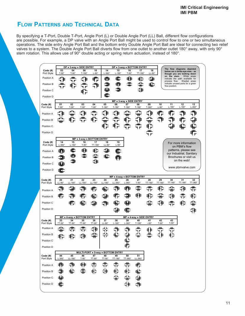
By specifying a T-Port, Double T-Port, Angle Port (L) or Double Angle Port (LL) Ball, different flow configurations are possible. For example, a DP valve with an Angle Port Ball might be used to control flow to one or two simultaneous operations. The side entry Angle Port Ball and the bottom entry Double Angle Port Ball are ideal for connecting two relief valves to a system. The Double Angle Port Ball diverts flow from one outlet to another outlet 180° away, with only 90° stem rotation. This allows use of 90° double acting or spring return actuation, instead of 180°.
FloW patterns and technical data
FLOW
PATTER
NS
For more information on PBM’s flow
patterns, please see our Industrial, Sanitary Brochures or visit us
on the web!
www.pbmvalve.com
DP ● 3-way ● SIDE ENTRY DP ● 3-way ● BOTTOM ENTRY Code (#) 03 04 06 10 14 15 16 17 18 Port Style T-90° T-90° T-180° L-90° L-360° L-180° T-90° TT-180° LL-90°
Position A
Position B
Position C
Position D
MP ● 3-way ● SIDE ENTRY Code (#) 01 02 03 04 05 06 07 08 09 10 11 12 13 Port Style T-90° T-90° T-90° T-90° T-180° T-180° T-180° T-180° T-360° L-90° L-180° L-180° L-360°
Position A
Position B
Position C
Position D
MP ● 3-way ● BOTTOM ENTRY Code (#) 14 15 16 17 18 19 Port Style L-360° L-180° T-90° TT-180° LL-90° L-90°
Position A
Position B
Position C
Position D
MP ● 4-way ● BOTTOM ENTRY Code (#) 20 21 22 23 24 25 26 27 28 29 30 31 32 Port Style LL-90° LL-180° LL-180° LL-180° LL-180° LL-360° L-360° T-90° TT-180° TT-180° TT-180° TT-180° TT-360°
Position A
Position B
Position C
Position D
MP ● 4-way ● BOTTOM ENTRY MP ● 4-way ● SIDE ENTRY Code (#) 33 34 35 36 37 38 39 40 41 42 43 Port Style TT-90° TT-90° TT-90° TT-90° LL-90° L-180° L-360° T-180° ─90° T-90° T-90°
Position A
Position B
Position C
Position D
MULTI-PORT ● 5-way ● BOTTOM ENTRY Code (#) 44 45 46 47 48 49 50 51 Port Style L-360° LL-180° T-90° TT-90° TT-90° TT-180° TT-360° LL-360°
Position A
Position B
Position C
Position D
The flow diagrams depicted below are a birds-eye-view - as though you are looking down on the stem. White areas indicate the path available for process flow. Shaded areas indicate unused ports for a given flow position.
11
IMI Critical EngineeringIMI PBM

www.pbmvalve.com
IMI PBM 1070 Sandy Hill Road, Irwin, PA 15642 USA
Tel: +1 800 967 4PBM / 724 863 0550 Fax: +1 724 864 9255
IMI Critical Engineering Lakeside, Solihull Parkway Birmingham Business Park Birmingham B37 7XZ United Kingdom
Tel: +44 (0)121 717 3700 Fax: +44 (0)121 717 3701
imi-critical.com