maria rosa ruiz - dspace.mit.edu
TRANSCRIPT

Design and Analysis of a Stewart-Platform-Based
Six-Axis Load Cell
by
Maria Rosa Ruiz
Submitted to the Department of Mechanical Engineeringin partial fulfillment of the requirements for the degree of
Bachelor of Science in Mechanical Engineering
at the
MASSACHUSETTS INSTITUTE OF TECHNOLOGY
June 2017
© Massachusetts Institute of Technology 2017. All rights reserved.
Author . . . . . . . . . . . . . . . . . . . . . . . . . . . . . . . . . . . . . . . . . . . . . . . . . . . . . . . . . . . . . .Department of Mechanical Engineering
May 17, 2017
Certified by. . . . . . . . . . . . . . . . . . . . . . . . . . . . . . . . . . . . . . . . . . . . . . . . . . . . . . . . . .H. Harry Asada
Ford Professor of EngineeringThesis Supervisor
Accepted by . . . . . . . . . . . . . . . . . . . . . . . . . . . . . . . . . . . . . . . . . . . . . . . . . . . . . . . . .Rohit Karnik
Associate Professor of Mechanical EngineeringUndergraduate Officer

2
Design and Analysis of a Stewart-Platform-Based Six-Axis
Load Cell
by
Maria Rosa Ruiz
Submitted to the Department of Mechanical Engineeringon May 17, 2017, in partial fulfillment of the
requirements for the degree ofBachelor of Science in Mechanical Engineering
Abstract
In this work, a six-axis load cell based on the geometry of a Stewart platform wasdeveloped. Its geometry and functional requirements were motivated by the needs ofrobotic limbs designed to be attached to human workers to support them in typicallyunergonomic positions. The sensor can measure forces and torques in six degrees offreedom, and can stably support the worker in various hanging positions while stillbeing sensitive to load measurements in different directions. Furthermore, it is madefrom inexpensive, commonly available cantilever beam load cells. In the least accuratedirection, Mx, our measurements were consistently 20% below the nominal appliedload. In the most accurate directions, Fx, My, and Mz, our measurements wereconsistently within 5% of the nominal applied loads. Performance can be optimizedusing the condition number of the transformation matrix. The full-scale version ofthe hex sensor is also designed and optimized based on its condition number.
Thesis Supervisor: H. Harry AsadaTitle: Ford Professor of Engineering
3

4

Acknowledgments
I would like to thank Daniel Gonzalez for being willing to share his impressive amounts
of mechanical engineering knowledge and for being the best mentor I could ask for,
Prof. Harry Asada for his advice and the opportunity to discover robotics research,
and Dr. Barbara Hughey for her help with data analysis and for introducing MIT
and mechanical engineering to me. I would also like to thank my parents and siblings
for their love and encouragement (and financial support), as well as Kath Xu, Melody
Liu, and all my friends for their unfailing confidence in me.
5

6

Contents
1 Motivation 13
1.1 Proposal: Extra Robotic Limbs (XRL) . . . . . . . . . . . . . . . . . 14
1.2 Sensing Between Robot and Human . . . . . . . . . . . . . . . . . . . 15
2 Design of Small Hex Sensor 17
2.1 Functional Requirements . . . . . . . . . . . . . . . . . . . . . . . . . 17
2.2 Design Process . . . . . . . . . . . . . . . . . . . . . . . . . . . . . . 18
2.3 Joint Design . . . . . . . . . . . . . . . . . . . . . . . . . . . . . . . . 20
2.4 Calculating Forces and Torques . . . . . . . . . . . . . . . . . . . . . 20
3 Measurement and Testing 25
4 Results and Analysis 27
4.1 Measured Values Compared to Actual Values . . . . . . . . . . . . . . 27
4.2 Noise . . . . . . . . . . . . . . . . . . . . . . . . . . . . . . . . . . . . 28
4.3 Sources of Error . . . . . . . . . . . . . . . . . . . . . . . . . . . . . . 30
4.3.1 Performance Analysis . . . . . . . . . . . . . . . . . . . . . . . 30
5 Preliminary Work on Full-Size Hex Sensor 33
5.1 Harness Selection . . . . . . . . . . . . . . . . . . . . . . . . . . . . . 33
5.2 Joint Design . . . . . . . . . . . . . . . . . . . . . . . . . . . . . . . . 34
5.3 Geometry Optimization . . . . . . . . . . . . . . . . . . . . . . . . . 35
5.4 Solid Model of Full Scale Hex Sensor . . . . . . . . . . . . . . . . . . 39
7

6 Conclusions and Future Work 41
8

List of Figures
1-1 Example of personal protective equipment, including SCBA system,
worn at the Fukushima site. . . . . . . . . . . . . . . . . . . . . . . . 14
1-2 The XRL in centaur mode, following behind a walking human; the XRL
in mantis mode, supporting the human doing work on the ground; and
the XRL in sitting mode, supporting the human like a chair. . . . . . 15
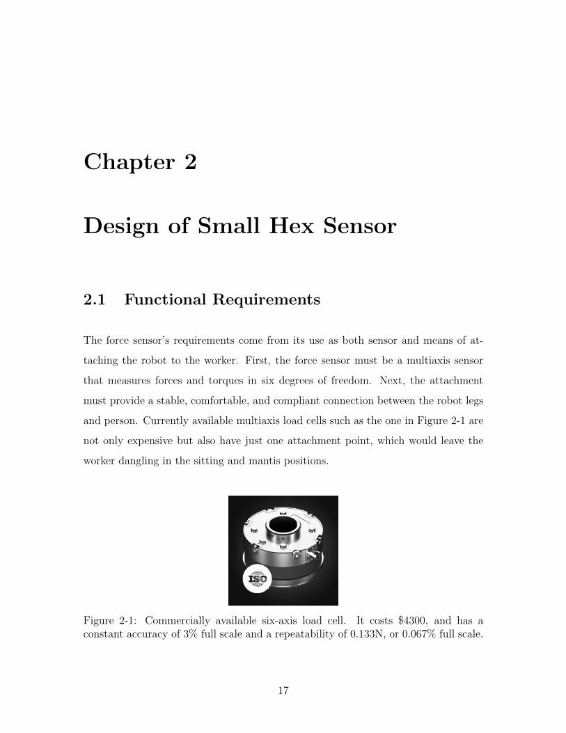
2-1 Commercially available six-axis load cell. It costs $4300, and has a
constant accuracy of 3% full scale and a repeatability of 0.133N, or
0.067% full scale. . . . . . . . . . . . . . . . . . . . . . . . . . . . . . 17
2-2 A typical Stewart platform, where the prismatic joints in the legs give
the top platform six degrees of freedom of motion. . . . . . . . . . . . 18
2-3 The total forces and moments on the load cell in the S-beam configu-
ration on the left are the same as if it were loaded conventionally, as
shown on the left (F = 0 and Msense = FL); therefore, there is no
parasitic loading to distort the readings. . . . . . . . . . . . . . . . . 19
2-4 The small hex sensor’s legs and platform before assembly, and the
completed hex sensor. . . . . . . . . . . . . . . . . . . . . . . . . . . . 20
2-5 Each leg reports an axial force, Nn . . . . . . . . . . . . . . . . . . . 21
2-6 Relevant angles and distances that determine overall geometry . . . . 21
2-7 For each pair of legs, the effective forces and moment at the top of the
triangle can be calculated. . . . . . . . . . . . . . . . . . . . . . . . . 22
9

2-8 The effective forces and moment at the top of each pair of legs can be
transformed again into the effective loads and torques applied at the
center of the top platform. . . . . . . . . . . . . . . . . . . . . . . . . 23
3-1 Test setup: the hex sensor was held in various orientations and known
weights hung from the sensor to test accuracy and repeatability. . . . 26
4-1 Sample plot of measured moment plotted against actual applied mo-
ment. The fit is linear and represents the proportional accuracy of the
measurement in this particular direction. . . . . . . . . . . . . . . . . 28
4-2 Signal readings after hex sensor was preloaded with 1kg and then ze-
roed; the noise range is about +/-0.03kg, or 1.1% FS. Power spectrum
for the signal: signal-to-noise ratio is roughly 30 dB. . . . . . . . . . . 29
5-1 To test rescue harness comfort, a subject was suspended from the ceil-
ing by three attachment points (circled in red) and comfort—especially
how the harness dug into the subject's body—was noted. . . . . . . . 34
5-2 The Yates Voyager 380 rescue harness . . . . . . . . . . . . . . . . . . 34
5-3 A typical D-ring on a rescue harness. The D-ring has three degrees of
freedom and can be approximated as a ball joint. . . . . . . . . . . . 35
5-4 Each pair of legs needs to constrain a total of 14 degrees of freedom,
and the ball joint from the harness attachment point constrained three
of these. Two options for joint combinations are displayed; the ball
joint and pin joint combination was chosen. . . . . . . . . . . . . . . 35
5-5 The six attachment points of each triangular pair of FSHS legs on the
XRL platform were the design parameters varied in the search for the
lowest condition number. . . . . . . . . . . . . . . . . . . . . . . . . . 36
5-6 H1 breaks down axial forces into their x, y, and z components. . . . . 37
5-7 Example plot of condition number; used as part of hill-climbing mini-
mization. . . . . . . . . . . . . . . . . . . . . . . . . . . . . . . . . . . 38
5-8 Diagram of optimal FSHS geometry . . . . . . . . . . . . . . . . . . . 39
10
5-9 Leg design . . . . . . . . . . . . . . . . . . . . . . . . . . . . . . . . . 39
5-10 Pair of legs . . . . . . . . . . . . . . . . . . . . . . . . . . . . . . . . 40
5-11 Solid model of proposed full-size hex sensor . . . . . . . . . . . . . . . 40
6-1 Load lifters are common hiking pack features that transfer weight from
the shoulders to the hips. . . . . . . . . . . . . . . . . . . . . . . . . . 42
6-2 The Second Spine can either be loose and flexible, or, when, pulled
into compression, rigid and load-bearing. . . . . . . . . . . . . . . . . 42
11

12

Chapter 1
Motivation
From cleaning up reactor meltdowns and former weapons production sites to regular
maintenance at nuclear power plants, nuclear site work requires hundreds of hours of
manual labor. Workers at both cleanup sites and normally operating power plants
complete a wide variety of tasks: at cleanup sites, they patch leaks and lay piping to
direct cooling water; during outages, they replace fuel and update equipment [1][6][7].
However, workers can only stay at the site for short time periods. Their per-
sonal protective equipment, which must include a self-contained breathing apparatus
(SCBA) and layers of stifling clothing, is bulky and heavy, making it difficult to ma-
neuver within the site and speeding up fatigue (see Figure 1-1). Because it lacks a
cooling system, the suit quickly becomes uncomfortably hot. Furthermore, workers
are limited by their air supply—even a 60-minute supply may yield only 15 minutes
of work time after exhaustion and time for decontamination steps are factored in [2].
Both outages and cleanup efforts are extremely expensive—outages, for example, last
an average of 35 days, cost the government millions, and force residents to pay more
to use conventionally-produced electricity. Improving the conditions for workers in
hazmat suits by increasing comfort and mobility will improve their work efficiency,
leading to cost savings.
13
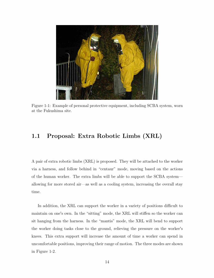
Figure 1-1: Example of personal protective equipment, including SCBA system, wornat the Fukushima site.
1.1 Proposal: Extra Robotic Limbs (XRL)
A pair of extra robotic limbs (XRL) is proposed. They will be attached to the worker
via a harness, and follow behind in “centaur” mode, moving based on the actions
of the human worker. The extra limbs will be able to support the SCBA system—
allowing for more stored air—as well as a cooling system, increasing the overall stay
time.
In addition, the XRL can support the worker in a variety of positions difficult to
maintain on one's own. In the “sitting” mode, the XRL will stiffen so the worker can
sit hanging from the harness. In the “mantis” mode, the XRL will bend to support
the worker doing tasks close to the ground, relieving the pressure on the worker's
knees. This extra support will increase the amount of time a worker can spend in
uncomfortable positions, improving their range of motion. The three modes are shown
in Figure 1-2.
14

Figure 1-2: The XRL in centaur mode, following behind a walking human; the XRLin mantis mode, supporting the human doing work on the ground; and the XRL insitting mode, supporting the human like a chair.
1.2 Sensing Between Robot and Human
The XRL will gather information about the worker's movements and the positions
of their limbs through a combination of a stereo camera on the worker's head for
simultaneous location and mapping and inertial measurement units (IMUs) on the
worker's limbs to capture body kinematics. There will also be a six axis force/torque
sensor at the attachment between robot and human. Although the IMUs can give
the position of the human's limbs in 3D space, the force sensor is an important safety
feature that gives the intentions of the operator: for example, when approaching an
obstacle, a force from the operator towards the robot signals that the operator is
trying to back away, and the robot can react accordingly. This thesis will focus on
the development and characterization of a small prototype force sensor with similar
geometry to the final force sensor, and present a figure of merit for evaluating force
sensors in this configuration.
15

16
Chapter 2
Design of Small Hex Sensor
2.1 Functional Requirements
The force sensor’s requirements come from its use as both sensor and means of at-
taching the robot to the worker. First, the force sensor must be a multiaxis sensor
that measures forces and torques in six degrees of freedom. Next, the attachment
must provide a stable, comfortable, and compliant connection between the robot legs
and person. Currently available multiaxis load cells such as the one in Figure 2-1 are
not only expensive but also have just one attachment point, which would leave the
worker dangling in the sitting and mantis positions.
Figure 2-1: Commercially available six-axis load cell. It costs $4300, and has aconstant accuracy of 3% full scale and a repeatability of 0.133N, or 0.067% full scale.
17

2.2 Design Process
A small, proof-of-concept version of the hex sensor (as the force sensor will now be
referred to) was designed to explore the geometry and method of sensing. Because
the attachment serves as both strap and sensor, the geometry of the attachment
must provide enough information to calculate all forces and torques between two
platforms using only axial force measurements along the connecting legs, and the
area of connection between the loading point and the base of the sensor must be large
to provide stability. A Stewart platform, shown in Figure 2-2, has a similar function,
providing six degrees of freedom of motion with only linear actuators while supporting
a platform. For the hex sensor, individual load cells were integrated into beams placed
into a hexapod configuration connecting two platforms: one representing the harness
attached to the person, and the other the robot.
Figure 2-2: A typical Stewart platform, where the prismatic joints in the legs givethe top platform six degrees of freedom of motion.
Next, different combinations of sensors and materials were considered for the legs,
which needed to measure forces applied axially. Either forces could be measured
directly, or measured strains could be combined with stiffness data to calculate force.
Possibilities for the legs included high-shore, preloaded stretch sensors; high-shore
rubber with strain gauges; and load cells. The stretch sensors recovered too slowly
after being stretched to be practical for a real-time application. Strain sensors cannot
withstand the strains on even the highest shore rubber. Load cells were chosen
18

because they were robust, accurate, and could be used in series with rubber for a
more compliant sensor.
For this hex sensor, 1-kg cantilever beam load cells were used, along with a Phid-
gets 4-Input bridge amplifier. Using the beam in an S-beam configuration allowed
forces to be measured in a straight line through the leg. Figure 2-3 shows how the
loading in the S-beam configuration is the same as when the load cell is loaded con-
ventionally.
Figure 2-3: The total forces and moments on the load cell in the S-beam configurationon the left are the same as if it were loaded conventionally, as shown on the left (F = 0and Msense = FL); therefore, there is no parasitic loading to distort the readings.
Each load cell was calibrated by assembling the leg, hanging 3 known weights
off each leg, and then finding a calibration constant A from the results such that
force = A ∗ voltage.
19

2.3 Joint Design
The joints connecting the legs to each platform had to be chosen to fully constrain
the two platforms. Using the 3D version of Gruebler's equation,
D.O.F. = 6(N − 1)− 5P5 − 4P4 − 3P3 − 2P2 − 1P1 (2.1)
where Pn represents the number of pairs that block n degrees of freedom, we can
calculate that to end up with 0 degrees of freedom for an 8-part mechanism made
from 6 beams and 2 plates, we need to constrain 42 degrees of freedom. For simplicity
and ease of manufacturing, and to ensure that the forces were transmitted purely
axially through the leg, 12 ball joints were used, so P3 = 12. The miniature hexapod
is left with 6 degrees of freedom, because each leg can spin in place, but the rotation
of each leg does not have a statistically significant effect on the measurement. The
ball joints were 3D printed.
Figure 2-4: The small hex sensor’s legs and platform before assembly, and the com-pleted hex sensor.
2.4 Calculating Forces and Torques
The geometry of the hex sensor can be used to calculate the effective forces and
torques at the center of the platform representing the robot from the axial forces felt
by each leg, shown in Figure 2-5. The axial forces are read in as a matrix, N .
20

Figure 2-5: Each leg reports an axial force, Nn
N =(N1 N2 N3 N4 N5 N6
)T(2.2)
The overall geometry is determined by the angles between the legs, and their
distance from the center of the platform, as shown in Figure 2-6.
Figure 2-6: Relevant angles and distances that determine overall geometry
First, we will focus on one pair of legs. The forces felt by these legs are represented
by
Na =(N1 N2
)T(2.3)
A transformation matrix, Ja, converts the forces felt in the pair of load cells to
the effective forces and moments felt at the top of the triangle formed by the pair, as
shown in Figure 2-7. Mz is the only direction of moment that can be distinguished
21

when given axial forces in a plane.
Figure 2-7: For each pair of legs, the effective forces and moment at the top of thetriangle can be calculated.
From the angles labeled in Figure 2-6, Ja can be calculated:
Ja =
cos(θ) sin(β) cos(θ) sin(β)
− sin(θ) − sin(θ)
− cos(θ) cos(β) − cos(θ) cos(β)
Db
2cos(θ) sin(β) −Db
2cos(θ) sin(β)
. (2.4)
The forces and moment at the top of each triangle are
Ftriangle = JaNa (2.5)
where
Ftriangle =(Fx Fy Fz Tz
)T. (2.6)
For the overall hex sensor, J1 converts all the axial forces, N from equation 2.2,
into forces and moment at the top of each pair of legs, perpendicular to the platform
22
but parallel to the triangle's base:
J1 =
Ja 0 0
0 Ja 0
0 0 Ja
(2.7)
This yields
F = J1N (2.8)
where
F = ( Fx1 Fy1 Fz1 Mz1 Fx2 Fy2 Fz2 Mz2 Fx3 Fy3 Fz3 Mz3 )T . (2.9)
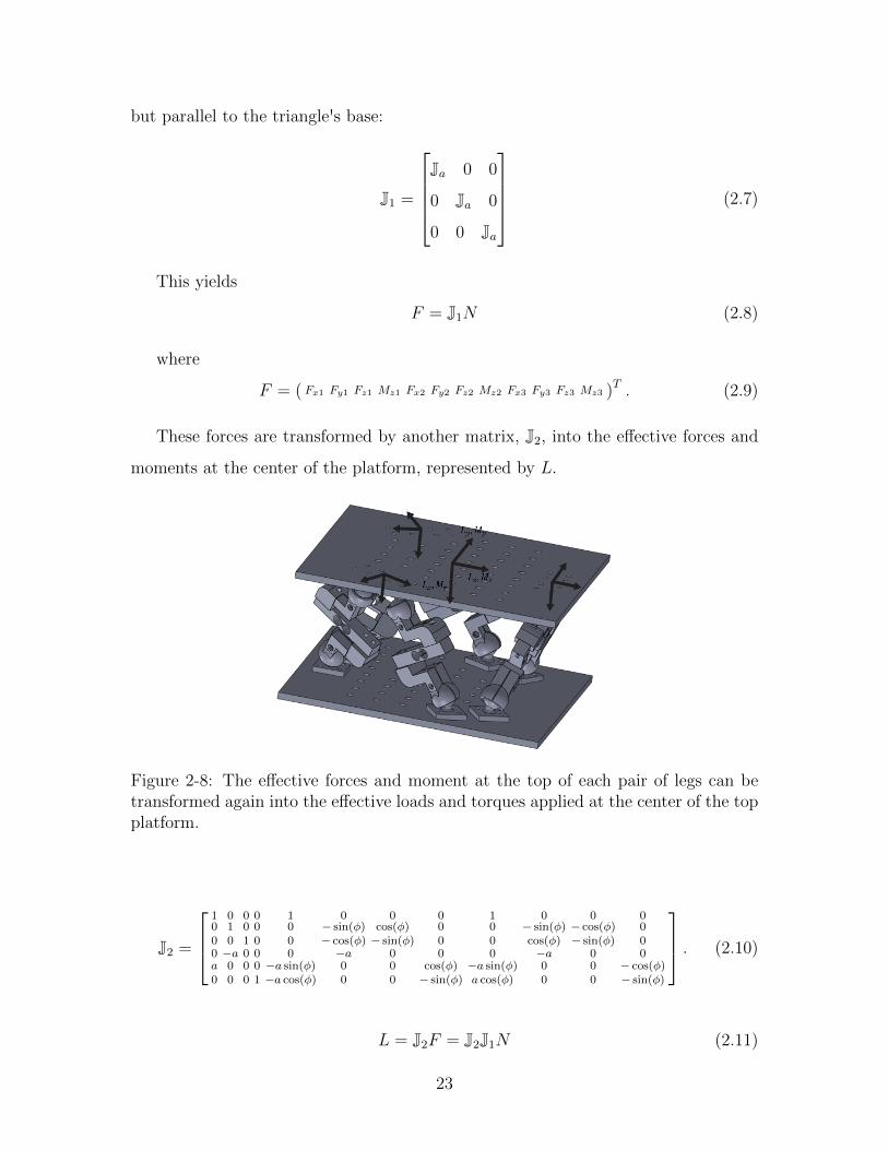
These forces are transformed by another matrix, J2, into the effective forces and
moments at the center of the platform, represented by L.
Figure 2-8: The effective forces and moment at the top of each pair of legs can betransformed again into the effective loads and torques applied at the center of the topplatform.
J2 =
1 0 0 0 1 0 0 0 1 0 0 00 1 0 0 0 − sin(φ) cos(φ) 0 0 − sin(φ) − cos(φ) 00 0 1 0 0 − cos(φ) − sin(φ) 0 0 cos(φ) − sin(φ) 00 −a 0 0 0 −a 0 0 0 −a 0 0a 0 0 0 −a sin(φ) 0 0 cos(φ) −a sin(φ) 0 0 − cos(φ)0 0 0 1 −a cos(φ) 0 0 − sin(φ) a cos(φ) 0 0 − sin(φ)
. (2.10)
L = J2F = J2J1N (2.11)
23

where
L =(Lx Ly Lz Mx My Mz
)T(2.12)
at the center of the platform.
24

Chapter 3
Measurement and Testing
The hex sensor was tested with known weights to determine its accuracy and repeata-
bility. To test force, a series of weights were hung under the center of the platform
representing the robot. To test moment, weights were hung a known distance away
from the center. The hex sensor was always preloaded with a 200g weight to decrease
the effects of play within the joints. Figure 3-1 shows the measurement test setup,
and the applied forces and torques are summarized in Table 3.1. The Python code
zeroed the hex sensor after the preload was applied, read the cantilever load cell val-
ues, and calculated the force or moment with the transformation matrices. Forces
and moments were measured in all 6 degrees of freedom, in both the positive and
negative directions.
Table 3.1: Applied forces and torques during testing.
Applied forces [N] Applied torques [N-m]
0.98 0.06224.90 0.31129.80 0.5601-0.98 -0.0622-4.90 -0.3112-9.80 -0.5601
The noise in the hex sensor's readings was also measured by preloading the sensor
with 1kg, zeroing it, and recording data over 10 seconds.
25

Figure 3-1: Test setup: the hex sensor was held in various orientations and knownweights hung from the sensor to test accuracy and repeatability.
26
Chapter 4
Results and Analysis
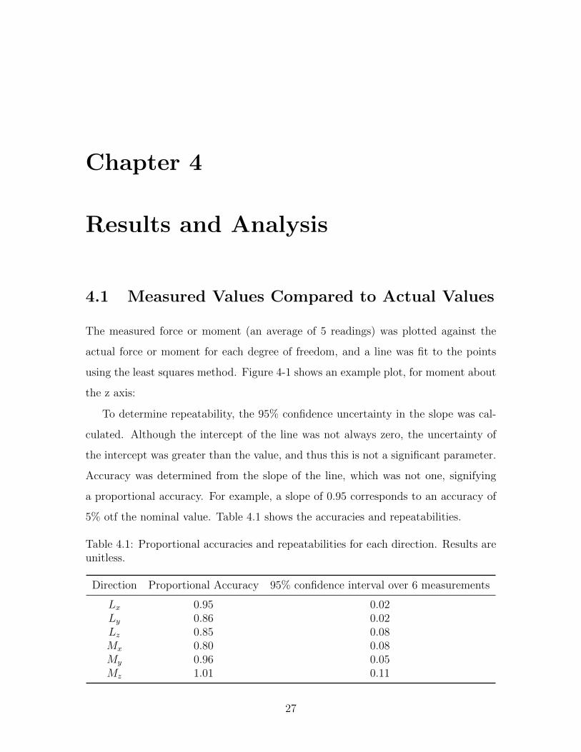
4.1 Measured Values Compared to Actual Values
The measured force or moment (an average of 5 readings) was plotted against the
actual force or moment for each degree of freedom, and a line was fit to the points
using the least squares method. Figure 4-1 shows an example plot, for moment about
the z axis:
To determine repeatability, the 95% confidence uncertainty in the slope was cal-
culated. Although the intercept of the line was not always zero, the uncertainty of
the intercept was greater than the value, and thus this is not a significant parameter.
Accuracy was determined from the slope of the line, which was not one, signifying
a proportional accuracy. For example, a slope of 0.95 corresponds to an accuracy of
5% otf the nominal value. Table 4.1 shows the accuracies and repeatabilities.
Table 4.1: Proportional accuracies and repeatabilities for each direction. Results areunitless.
Direction Proportional Accuracy 95% confidence interval over 6 measurements
Lx 0.95 0.02Ly 0.86 0.02Lz 0.85 0.08Mx 0.80 0.08My 0.96 0.05Mz 1.01 0.11
27
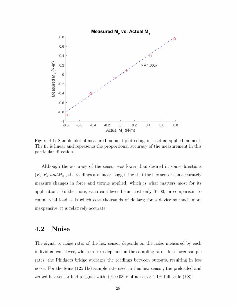
Figure 4-1: Sample plot of measured moment plotted against actual applied moment.The fit is linear and represents the proportional accuracy of the measurement in thisparticular direction.
Although the accuracy of the sensor was lower than desired in some directions
(Fy, Fz, andMx), the readings are linear, suggesting that the hex sensor can accurately
measure changes in force and torque applied, which is what matters most for its
application. Furthermore, each cantilever beam cost only $7.00, in comparison to
commercial load cells which cost thousands of dollars; for a device so much more
inexpensive, it is relatively accurate.
4.2 Noise
The signal to noise ratio of the hex sensor depends on the noise measured by each
individual cantilever, which in turn depends on the sampling rate—for slower sample
rates, the Phidgets bridge averages the readings between outputs, resulting in less
noise. For the 8-ms (125 Hz) sample rate used in this hex sensor, the preloaded and
zeroed hex sensor had a signal with +/- 0.03kg of noise, or 1.1% full scale (FS).
28

The power spectrum for the signal was also plotted up to the Nyquist frequency,
62.5 Hz, which is the highest frequency that can be unambiguously measured. The
signal-to-noise ratio is about 20 dB. The power spectrum is relatively flat, meaning
there are no unwanted periodic signals corrupting the data.
Figure 4-2: Signal readings after hex sensor was preloaded with 1kg and then zeroed;the noise range is about +/-0.03kg, or 1.1% FS. Power spectrum for the signal: signal-to-noise ratio is roughly 30 dB.
29
4.3 Sources of Error
First, the load cells have a repeatability error of 0.05% FS, or about 0.5g, a couple of
orders of magnitude less than the measured error. Therefore, the load cells themselves
cannot account for most of the measured error.
Next, to ensure that the error did not come from inaccurately assembling the hex
sensor, the attachment angles were varied slightly in the code to predict the effect
of errors in assembly. Even varying the angle of attachment up to an unrealistic 5
degrees did not change the output by more than 6%, suggesting that the assembly
process is not responsible for most of the error.
Finally, the ball joints were 3D printed, resulting in rough surfaces within the ball
joint. Furthermore, the socket assembly allowed play if not tightened enough, but
compressed the ball, creating more friction, if overtightened. This could cause the
load to not be perfectly axially transmitted.
4.3.1 Performance Analysis
The geometry of the hex sensor can also be analyzed to determine its effects on the
sensitivity of the sensor in different directions. We can evaluate the effectiveness of
the geometry through the evaluation of the overall transformation matrix J:
J = J2J1 (4.1)
We want the errors in the measurement of the axial forces to be magnified as little
as possible by the transformation matrix [8]. For forces applied to each leg such that
N is a unitary matrix, the tip of the output vector of forces and moments will be
inside an ellipsoid defined by the singular value decomposition of J, similar to how
manipulability is determined by the shape of the velocity ellipsoid.
J = UΣVT (4.2)
where U and V are orthogonal matrices composed of the eigenvectors of JJT and
30
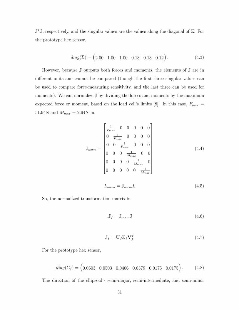
JTJ, respectively, and the singular values are the values along the diagonal of Σ. For
the prototype hex sensor,
diag(Σ) =(
2.00 1.00 1.00 0.13 0.13 0.12). (4.3)
However, because J outputs both forces and moments, the elements of J are in
different units and cannot be compared (though the first three singular values can
be used to compare force-measuring sensitivity, and the last three can be used for
moments). We can normalize J by dividing the forces and moments by the maximum
expected force or moment, based on the load cell's limits [8]. In this case, Fmax =
51.94N and Mmax = 2.94N-m.
Jnorm =
1Fmax
0 0 0 0 0
0 1Fmax
0 0 0 0
0 0 1Fmax
0 0 0
0 0 0 1Mmax
0 0
0 0 0 0 1Mmax
0
0 0 0 0 0 1Mmax
(4.4)
Lnorm = JnormL (4.5)
So, the normalized transformation matrix is
.Jf = JnormJ (4.6)
Jf = UfΣfVTf (4.7)
For the prototype hex sensor,
diag(Σf ) =(
0.0503 0.0503 0.0406 0.0379 0.0175 0.0175). (4.8)
The direction of the ellipsoid’s semi-major, semi-intermediate, and semi-minor
31
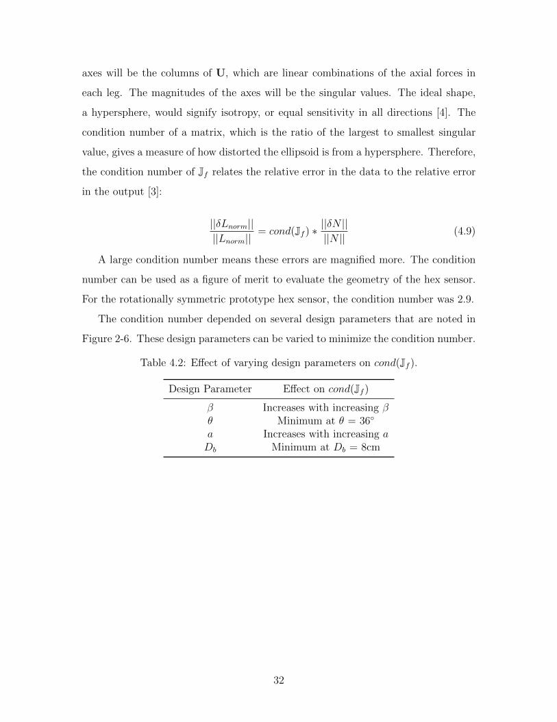
axes will be the columns of U, which are linear combinations of the axial forces in
each leg. The magnitudes of the axes will be the singular values. The ideal shape,
a hypersphere, would signify isotropy, or equal sensitivity in all directions [4]. The
condition number of a matrix, which is the ratio of the largest to smallest singular
value, gives a measure of how distorted the ellipsoid is from a hypersphere. Therefore,
the condition number of Jf relates the relative error in the data to the relative error
in the output [3]:
||δLnorm||||Lnorm||
= cond(Jf ) ∗||δN ||||N ||
(4.9)
A large condition number means these errors are magnified more. The condition
number can be used as a figure of merit to evaluate the geometry of the hex sensor.
For the rotationally symmetric prototype hex sensor, the condition number was 2.9.
The condition number depended on several design parameters that are noted in
Figure 2-6. These design parameters can be varied to minimize the condition number.
Table 4.2: Effect of varying design parameters on cond(Jf ).
Design Parameter Effect on cond(Jf )
β Increases with increasing βθ Minimum at θ = 36◦
a Increases with increasing aDb Minimum at Db = 8cm
32
Chapter 5
Preliminary Work on Full-Size Hex
Sensor
Next, the learnings from the small hex sensor were applied to the full-size hex sensor
(FSHS) that will connect the XRL to the worker via the harness.
5.1 Harness Selection
The XRL will be mounted to a vertical platform; the FSHS will connect the platform
and the harness worn by the worker. The harness should comfortably hold the worker
in the sitting and mantis positions. A rescue harness was chosen for its ability to
support the wearer in multiple directions. The hex sensor design requires that the
sensor be attached to the harness in three places: either with two connections at
the shoulders and one at the lower back, or two at the hips and one at the upper
back. Through tests it was found that the former—two shoulder connections and one
lumbar connection—was the most comfortable. Figure 5-1 shows a rescue harness
with the attachments in this configuration.
The Yates Voyager 380 rescue harness was chosen for its D-ring location.
33

Figure 5-1: To test rescue harness comfort, a subject was suspended from the ceilingby three attachment points (circled in red) and comfort—especially how the harnessdug into the subject's body—was noted.
Figure 5-2: The Yates Voyager 380 rescue harness
5.2 Joint Design
The FSHS differs from the smaller version in that the legs could only be connected
to the worker's harness at three points instead of six points. The harness's included
D-rings allow movement with six degrees of freedom, so they were approximated as
three ball joints. A typical D-ring is shown in Figure 5-3.
Using Equation 2.1 again, we must constrain 42 degrees of freedom. This time,
P3 = 3 represents our 3 ball joint attachments. There are 33 degrees of freedom
left, or 11 degrees of freedom per pair of legs. Figure 5-4 shows some possible joint
34

Figure 5-3: A typical D-ring on a rescue harness. The D-ring has three degrees offreedom and can be approximated as a ball joint.
combinations to reach this constraint. Two ball joints and a pin joint were chosen.
Note that the 11 degrees of freedom per pair of legs made it impossible to have a
symmetric set of joints.
Figure 5-4: Each pair of legs needs to constrain a total of 14 degrees of freedom, andthe ball joint from the harness attachment point constrained three of these. Twooptions for joint combinations are displayed; the ball joint and pin joint combinationwas chosen.
5.3 Geometry Optimization
Similar to the small hex sensor, the FSHS has a transformation matrix that turns
the axial forces in each leg into the force/torque output. The design parameters for
the FSHS are the attachment locations on the XRL (the attachment locations on the
35
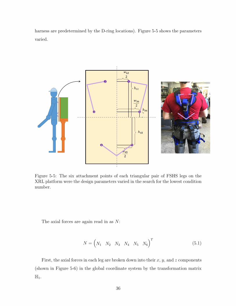
harness are predetermined by the D-ring locations). Figure 5-5 shows the parameters
varied.
Figure 5-5: The six attachment points of each triangular pair of FSHS legs on theXRL platform were the design parameters varied in the search for the lowest conditionnumber.
The axial forces are again read in as N :
N =(N1 N2 N3 N4 N5 N6
)T(5.1)
First, the axial forces in each leg are broken down into their x, y, and z components
(shown in Figure 5-6) in the global coordinate system by the transformation matrix
H1.
36
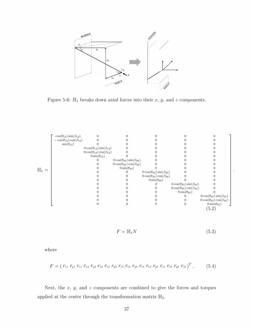
Figure 5-6: H1 breaks down axial forces into their x, y, and z components.
H1 =
cos(θ12) sin(β12) 0 0 0 0 0− cos(θ12) cos(β12) 0 0 0 0 0
sin(θ12) 0 0 0 0 00 cos(θ12) sin(β12) 0 0 0 00 cos(θ12) cos(β12) 0 0 0 0
0 sin(θ12) 0 0 0 00 0 cos(θ36) sin(β36) 0 0 00 0 cos(θ36) cos(β36) 0 0 00 0 sin(θ36) 0 0 00 0 0 cos(θ36) sin(β36) 0 00 0 0 cos(θ36) cos(β36) 0 00 0 0 sin(θ36) 0 00 0 0 0 cos(θ45) sin(β45) 00 0 0 0 cos(θ45) cos(β45) 00 0 0 0 sin(θ45) 00 0 0 0 0 cos(θ45) sin(β45)0 0 0 0 0 cos(θ45) cos(β45)0 0 0 0 0 sin(θ45)
.
(5.2)
F = H1N (5.3)
where
F = ( Fx1 Fy1 Fz1 Fx2 Fy2 Fz2 Fx3 Fy3 Fz3 Fx4 Fy4 Fz4 Fx5 Fy5 Fz5 Fx6 Fy6 Fz6 )T . (5.4)
Next, the x, y, and z components are combined to give the forces and torques
applied at the center through the transformation matrix H2.
37
H2 =
1 0 0 1 0 0 1 0 0 1 0 0 1 0 0 1 0 00 1 0 0 1 0 0 1 0 0 1 0 0 1 0 0 1 00 0 1 0 0 1 0 0 1 0 0 1 0 0 1 0 0 10 0
w122
0 0−w12
20 0
−w362
0 0−w45
20 0
w452
0 0w362
h122
0 0h122
0 0h362
0 0h−45
20 0
h−452
0 0h362
0 0−w12
20 0
w122
0 0w362
0 0w452
0 0−w45
20 0
−w362
0 0
. (5.5)
L = H2F (5.6)
where
L =(Lx Ly Lz Mx My Mz
)T. (5.7)
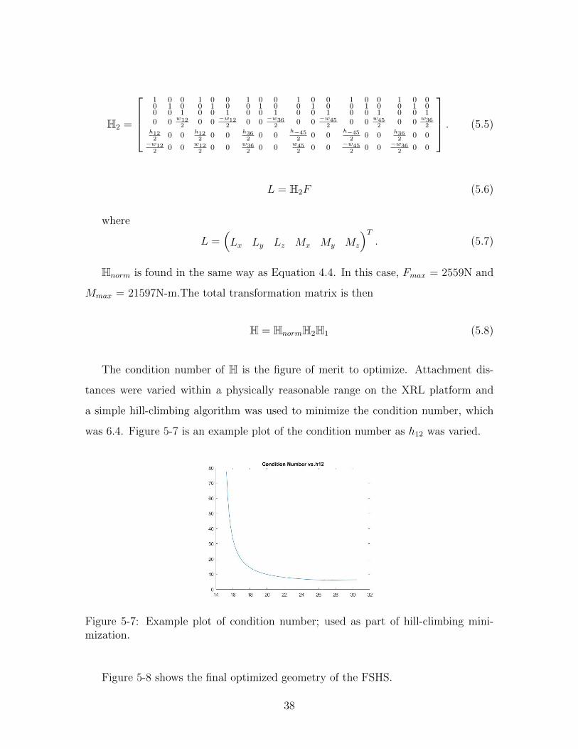
Hnorm is found in the same way as Equation 4.4. In this case, Fmax = 2559N and
Mmax = 21597N-m.The total transformation matrix is then
H = HnormH2H1 (5.8)
The condition number of H is the figure of merit to optimize. Attachment dis-
tances were varied within a physically reasonable range on the XRL platform and
a simple hill-climbing algorithm was used to minimize the condition number, which
was 6.4. Figure 5-7 is an example plot of the condition number as h12 was varied.
Figure 5-7: Example plot of condition number; used as part of hill-climbing mini-mization.
Figure 5-8 shows the final optimized geometry of the FSHS.
38
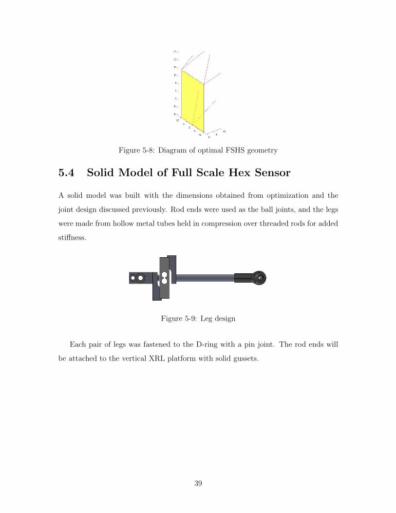
Figure 5-8: Diagram of optimal FSHS geometry
5.4 Solid Model of Full Scale Hex Sensor
A solid model was built with the dimensions obtained from optimization and the
joint design discussed previously. Rod ends were used as the ball joints, and the legs
were made from hollow metal tubes held in compression over threaded rods for added
stiffness.
Figure 5-9: Leg design
Each pair of legs was fastened to the D-ring with a pin joint. The rod ends will
be attached to the vertical XRL platform with solid gussets.
39

Figure 5-10: Pair of legs
Figure 5-11: Solid model of proposed full-size hex sensor
40
Chapter 6
Conclusions and Future Work
This work presents the design and analysis of a prototype hexapod-based multiaxis
force sensor with a geometry that allows it to be used as both a load cell and at-
tachment between extra robot limbs and their human operator. A figure of merit,
the condition number, is used to compare the effectiveness of different geometries. A
full-scale hex sensor (FSHS) is then designed using the condition number to guide
the geometry.
The small hex sensor will be used to implement real-time force sensing, and com-
bined with a small-scale set of XRL to create a prototype human follower. However,
most future work will focus on the FSHS. The effect of attaching the FSHS to a
compliant harness instead of a rigid platform will be studied, especially the possible
movement of the attachment points due to the stretchiness of the fabric and the re-
sulting loss of accuracy of the measured forces. The compliant harness will also act
as a spring, introducing a resonant frequency than can be pinpointed with a Fourier
transform. The design may need to be altered to ensure the resonant frequency is
higher than typical walking frequencies. Finally, safety features must be considered
for situations in which the XRL motors fail and the worker is left carrying the weight
of the XRL by himself, or in which the worker slips and applies a sudden force on the
sensors. Possible harness alterations to protect the worker in case of motor failure
include load lifters like those found on hiking backpacks that can be tightened in case
of an emergency to transfer the weight of the XRL from the shoulders to the waist
41
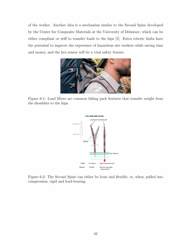
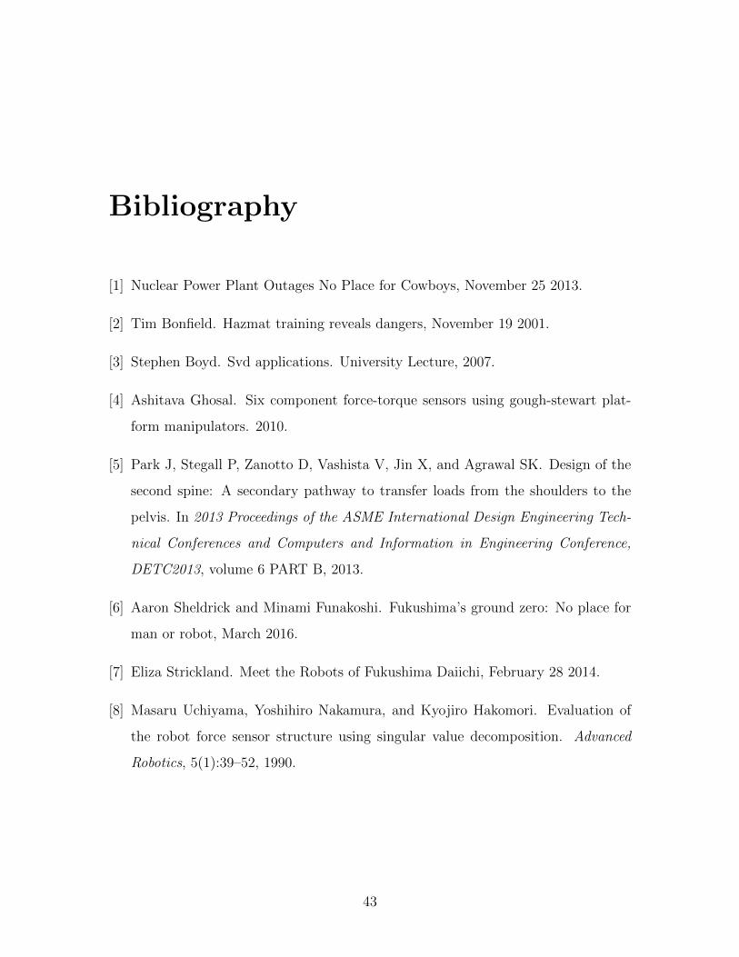
of the worker. Another idea is a mechanism similar to the Second Spine developed
by the Center for Composite Materials at the University of Delaware, which can be
either compliant or stiff to transfer loads to the hips [5]. Extra robotic limbs have
the potential to improve the experience of hazardous site workers while saving time
and money, and the hex sensor will be a vital safety feature.
Figure 6-1: Load lifters are common hiking pack features that transfer weight fromthe shoulders to the hips.
Figure 6-2: The Second Spine can either be loose and flexible, or, when, pulled intocompression, rigid and load-bearing.
42
Bibliography
[1] Nuclear Power Plant Outages No Place for Cowboys, November 25 2013.
[2] Tim Bonfield. Hazmat training reveals dangers, November 19 2001.
[3] Stephen Boyd. Svd applications. University Lecture, 2007.
[4] Ashitava Ghosal. Six component force-torque sensors using gough-stewart plat-
form manipulators. 2010.
[5] Park J, Stegall P, Zanotto D, Vashista V, Jin X, and Agrawal SK. Design of the
second spine: A secondary pathway to transfer loads from the shoulders to the
pelvis. In 2013 Proceedings of the ASME International Design Engineering Tech-
nical Conferences and Computers and Information in Engineering Conference,
DETC2013, volume 6 PART B, 2013.
[6] Aaron Sheldrick and Minami Funakoshi. Fukushima’s ground zero: No place for
man or robot, March 2016.
[7] Eliza Strickland. Meet the Robots of Fukushima Daiichi, February 28 2014.
[8] Masaru Uchiyama, Yoshihiro Nakamura, and Kyojiro Hakomori. Evaluation of
the robot force sensor structure using singular value decomposition. Advanced
Robotics, 5(1):39–52, 1990.
43