march, rad1oa television news...
TRANSCRIPT
RAD1Oa TELEVISION
NEWS
MARCH, 1950
RADIOinELECTRONIC
TELEVISION
RADAR
ELECTRONICS
RESEARCH
COMMUNICATIONS
MAINTENANCE
RAD10h
RRDIO
TryJe M.ek RvÑate.M l'yten, eft I,
ELECTRONICS COMMUNICATIONS TELEVISION RESEARCH
MARCH, 1950
MAINTENANCE
MICROWAVE STANDING WAVE DETECTORS Samuel Freedman 3
STRAIN GAUGE LINK Alvin B. Kaufman 7
U.H.F. TV CONVERTER DESIGN Nicholas Simopoulos IO
CRYSTAL SAVERS Harold E. Bryan 12
MICROWAVE TRANSMISSION LINES J. Racker 14
MAGNETIC FLUX COMPARATOR Edwin N. Kaufman 20
TE00 WAVES IN RECTANGULAR WAVE GUIDES 32
DEPARTMENTS NEWS BRIEFS 22 PERSONALS 26
NEW PRODUCTS 24 TECHNICAL BOOKS 29
RADIO -ELECTRONIC ENGINEERING is published each month as a special edition in a limited number of copies of RADIO & TELEVISION NEWS, by the Ziff -Davis Publishing Company, 185 N. Wabash Avenue, Chicago 1, Illinois.
VOLUME 14, NUMBER 3, Copyright, 1950, Ziff -Davis Publishing Company
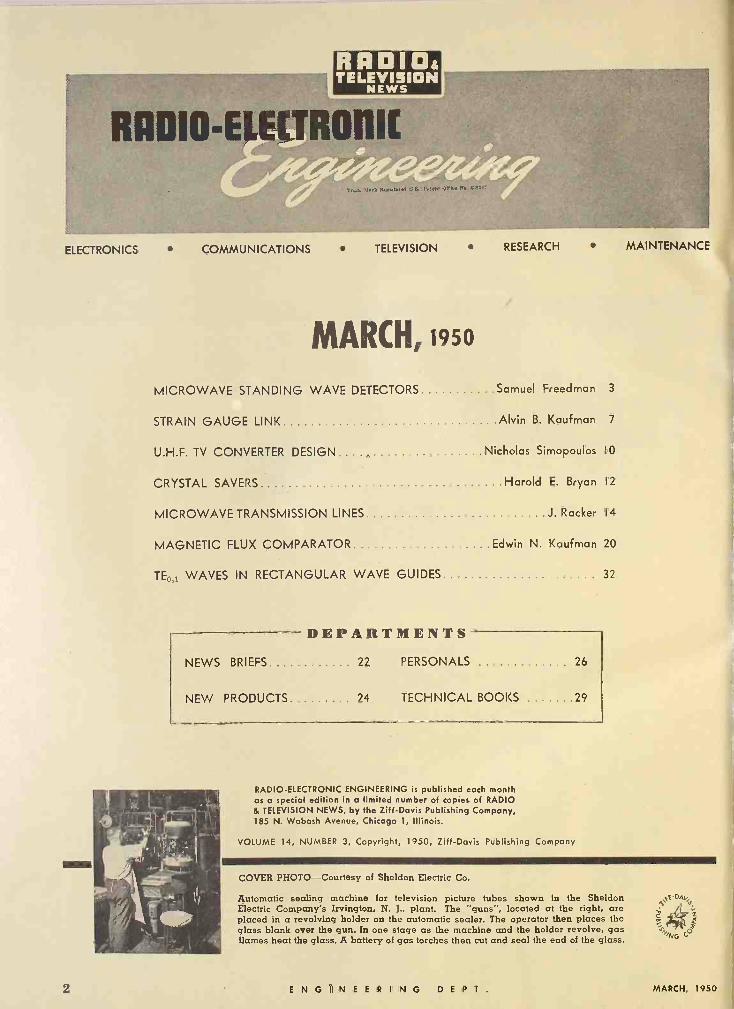
COVER PHOTO-Courtesy of Sheldon Electric Co.
Automatic sealing machine for television picture tubes shown in the Sheldon Electric Company's Irvington, N. J., plant. The "guns", located at the right, are placed in a revolving holder on the automatic sealer. The operator then places the glass blank over the gun. In one stage as the machine and the holder revolve, gas flames heat the glass. A battery of gas torches then cut and seal the end of the glass.
e,
°a
2 ENGINEERING D E P T. MARCH, 1950
i
i
MICROWAVE
STANDING WAVE
DETECTORS By SAMUEL FREEDMAN
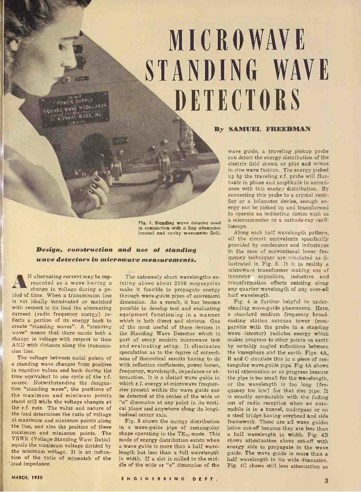
Fig. 1. Standing wave detector used in conjunction with a flap attenuator (center) and cavity wavemeter (left).
Design, construction and use of standing wave detectors in microwave measurements.
AN alternating current may be rep- resented as a wave having a change in voltage during a pe-
riod of time. When a transmission line is not ideally terminated or matched with respect to its load the alternating current (radio frequency energy) re- flects a portion of its energy back to create "standing waves". A "standing wave" means that there exists both a change in voltage with respect to time AND with distance along the transmis- sion line.
The voltage between nodal points of a standing wave changes from positive to negative values and back during the time equivalent to one cycle of the r.f. source. Notwithstanding the designa- tion "standing wave", the positions of the maximum and minimum points stand still while the voltage changes at the r.f. rate. The value and nature of the load determines the ratio of voltage at maximum and minimum points along the line, and also the position of these maximum and minimum points. The VSWR (Voltage Standing Wave Ratio) equals the maximum voltage divided by the minimum voltage. It is an indica- tion of the ratio of mismatch of the
' load impedance.
The extremely short wavelengths ex- isting above about 2500 megacycles make it feasible to propagate energy through wave -guide pipes of convenient dimension. As a result, it has become possible to develop test and evaluating equipment functioning in a manner which is both direct and obvious. One of the most useful of these devices is the Standing Wave Detector which is part of every modern microwave test and evaluating setup. It eliminates speculation as to the degree of correct- ness of theoretical results having to do with reflection coefficients, power losses, frequency, wavelength, impedance or at- tenuation. It is a slotted wave guide in which r.f. energy at microwave frequen- cies present within the wave guide can be detected at the center of the wide or "a" dimension at any point in its verti- cal plane and anywhere along its longi- tudinal center axis.
Fig. 3 shows the energy distribution in a wave -guide pipe of rectangular shape operating in the TE0,, mode. This mode of energy distribution exists when a wave guide is more than a half wave- length but less than a full wavelength in width. If a slot is milled in the mid- dle of the wide or "a" dimension of the
wave guide, a traveling pickup probe can detect the energy distribution of the electric field shown as plus and minus in sine wave fashion. The energy picked up by the traveling r.f. probe will fluc- tuate in phase and amplitude in accord- ance with this energy distribution. By connecting this probe to a crystal recti- fier or a bolometer device, enough en- ergy can be picked up and transformed to operate an indicating device such as a microammeter or a cathode-ray oscil- loscope.
Along each half wavelength pattern, all the circuit equivalents specifically provided by condensers and inductance in the case of conventional lower fre- quency techniques are simulated as il- lustrated in Fig. 2. It is in reality a microwave transformer making use of inversion capacitive, inductive and transformation effects existing along any quarter wavelength of any over-all half wavelength.
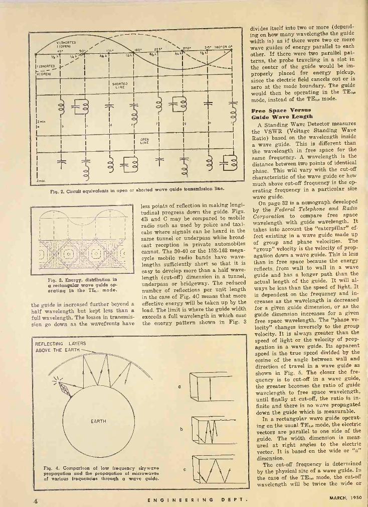
Fig. 4 is further helpful in under- standing wave -guide phenomena. Here, a standard medium frequency broad- casting station antenna tower (com- parable with the probe in a standing wave detector) radiates energy which makes progress to other points on earth by suitably angled reflections between the ionosphere and the earth. Figs. 4A, B and C simulate this in a piece of rec- tangular wave -guide pipe. Fig 4A shows total attenuation or no progress because the pipe is too small for the wavelength, or the wavelength is too long (fre- quency too low) for that size pipe. It is exactly comparable with the fading out of radio reception when an auto- mobile is in a tunnel, underpass or on a steel bridge having overhead and side framework. These are all wave guides below cut-off because they are less than a half wavelength in width. Fig. 4B shows attentuation above cut-off with energy able to propagate in the wave guide. The wave guide is more than a half wavelength in its wide dimension. Fig. 4C shows still less attenuation as
MARCH, 1950 E N G I N E E R I N G D E P T. 3
V(SHORTED I (OPEN) / 45 90 % I. e
/0 r1 /4 a
(SHORTED TL I
FV(OPENI' I I
Sp a
I
I SHORTED I L NE
0
I60 20* S/! a
\ 270 315 360.OR
J/q,. 7/6 aI. X
I \\ 1
I I
II
OPEN LINE
T
Fig. 2. Circuit equivalents in open or shorted wave guide transmission line.
\ 1I II
fl1
_ -- r-s x
5 -,----7. 'z'-,-----,-'sY xiilk ' i Ì 11.1Ì1O i li' ¡Hp,' . II i( '_ ...) *1, . ,__J, II, 1 ,_ I#Y _- III;_sc -I ii-=- -l'Iii a = 'I-- -- -- g_,-- - -
Fig. 3. Energy, distribution in a rectangular wave guide op- erating in the TE0,, mode.
the guide is increased further beyond a half wavelength but kept less than a full wavelength. The losses in transmis- sion go down as the wavefronts have
less points of reflection in making longi- tudinal progress down the guide. Figs. 4B and C may be compared to mobile radio such as used by police and taxi- cabs where signals can be heard in the same tunnel or underpass while broad- cast reception in private automobiles cannot. The 30-40 or the 152-162 mega- cycle mobile radio bands have wave- lengths sufficiently short so that it is
easy to develop more than a half wave- length (cut-off) dimension in a tunnel, underpass or bridgeway. The reduced number of reflections per unit length in the case of Fig. 4C means that more effective energy will be taken up by the load. The limit is where the guide width exceeds a full wavelength in which case the energy pattern shown in Fig. 3
REFLECTING LAYERS
ABOVE THE EARTH
b
`C \N\
Fig. 4. Comparison of low frequency skywave propagation and the propagation of microwaves of various frequencies through a wave guide.
divides itself into two or more (depend- ing on how many wavelengths the guide width is) as if there were two or more
wave guides of energy parallel to each
other. If there were two parallel pat- terns, the probe traveling in a slot in
the center of the guide would be im-
properly placed for energy pickup, since the electric field cancels out or is
zero at the mode boundary. The guide would then be operating in the mode, instead of the TE,,, mode.
Free Space Versus Guide Wave Length
A Standing Wave Detector measures the VSWR (Voltage Standing Wave Ratio) based on the wavelength inside
a wave guide. This is different than the wavelength in free space for the same frequency. A wavelength is the
distance between two points of identical phase. This will vary with the cut-off
characteristic of the wave guide or how
much above cut-off frequency is the op-
erating frequency in a particular size
wave guide. On page 32 is a nomograph developed
by the Federal Telephone and Radio
Corporation to compare free space wavelength with guide wavelength. It takes into account the "caterpillar" ef-
fect existing in a wave guide made up of group and phase velocities. The "group" velocity is the velocity of prop- agation down a wave guide. This is less than in free space because the energy reflects from wall to wall in a wave guide and has a longer path than the actual length of the guide. It will al- ways be less than the speed of light. It is dependent on the frequency and in-
creases as the wavelength is decreased for a given guide dimension, or as the guide dimension increases for a given free space wavelength. The "phase ve-
locity" changes inversely to the group velocity. It is always greater than the speed of light or the velocity of prop- agation in a wave guide. Its apparent speed is the true speed divided by the cosine of the angle between wall and direction of travel in a wave guide as shown in Fig. 5. The closer the fre- quency is to cut-off in a wave guide, the greater becomes the ratio of guide wavelength to free space wavelength, until finally at cut-off, the ratio is in-
finite and there is no wave propagated down the guide which is measurable.
In a rectangular wave guide operat- ing on the usual TE,,, mode, the electric vectors are parallel to one side of the guide. The width dimension is meas-
ured at right angles to the electric vector. It is based on the wide or "a" dimension.
The cut-off frequency is determined by the physical size of a wave guide. In the case of the TE,,, mode, the cut-off wavelength will be twice the wide or
4 ENGINEERING D E P T. MARCH, 1950
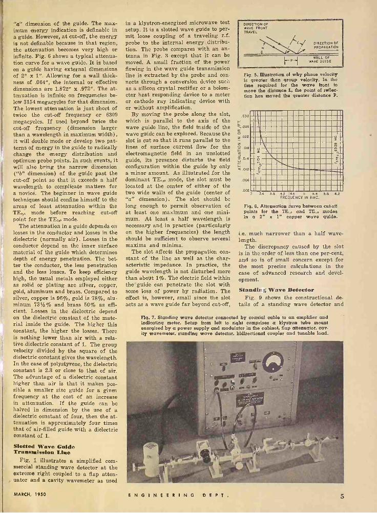
"a" dimension of the guide. The max- imum energy indication is definable in a guide. However, at cut-off, the energy is not definable because in that region, the attenuation becomes very high or infinite. Fig. 6 shows a typical attenua- tion curve for a wave guide. It is based on a guide having external dimensions of 2" x 1". Allowing for a wall thick- ness of .064", the internal or effective dimensions are 1.872" x .972". The at- tenuation is infinite on frequencies be- low 3154 megacycles for that dimension. The lowest attenuation is just short of twice the cut-off frequency or 6309 megacycles. If used beyond twice the cut-off frequency (dimension larger than a wavelength in maximum width), it will double mode or develop two pat- terns of energy in the guide to radically change the energy distribution and optimum probe points. In such events, it will also bring the narrow dimension ("b" dimension) of the guide past the cut-off point so that it exceeds a half wavelength to complicate matters for a novicè. The beginner in wave guide techniques should confine himself to the areas of least attenuation within the TEO,r mode before reaching cut-off point for the TE2,O mode.
The attenuation in a guide depends on losses in the conductor and losses in the dielectric (normally air). Losses in the conductor depend on the inner surface material of the guide which determines depth of energy penetration. The bet- ter the conductor, the less penetration and the less losses. To keep efficiency high, the usual metals employed either as solid or plating are silver, copper, gold, aluminum and brass. Compared to silver, copper is 96%, gold is 78%, alu- minum 731% and brass 50% as effi- cient. Losses in the dielectric depend on the dielectric constant of the mate- rial inside the guide. The higher this constant, the higher the losses. There is nothing lower than air with a rela- tive dielectric constant of 1. The group velocity divided by the square of the dielectric constant gives the wavelength. In the case of polystyrene, the dielectric constant is 2.3 or close to that of air. The advantage of a dielectric constant higher than air is that it makes pos- sible a smaller size guide for a given frequency at the cost of an increase in attenuation. If the guide can be halved in dimension by the use of a dielectric constant of four, then the at- tenuation is approximately four times that of air -filled guide with a dielectric constant of 1.
Slotted Wave Guide Transmission Line
Fig. 1 illustrates a simplified com- mercial standing wave detector at the extreme right coupled to a flap atten- uator and a cavity wavemeter as used
in a klystron -energized microwave test setup. It is a slotted wave guide to per- mit loose coupling of a traveling r.f. probe to the internal energy distribu- tion. The probe compares with an an- tenna in Fig. 3 except that it can be moved. A small fraction of the power flowing in the wave guide transmission line is extracted by the probe and con- nects through a conversion device such as a silicon crystal rectifier or a bolom- eter heat responding device to a meter or cathode ray indicating device with or without amplification.
By moving the probe along the slot, which is parallel to the axis of the wave guide line, the field inside of the wave guide can be explored. Because the slot is cut so that it runs parallel to the lines of surface current flow for the electromagnetic field in an unslotted guide, its presence disturbs the field configuration within the guide by only a minor amount. As illustrated for the dominant TE1,o mode, the slot must be located at the center of either of the two wide walls of the guide (center of "a" dimension). The slot should be long enough to permit observation of at least one maximum and one mini- mum. At least a half wavelength is necessary and in practice (particularly on the higher frequencies) the length should be sufficient to observe several maxima and minima.
The slot affects the propagation con- stant of the line as well as the char- acteristic impedance. In practice, the guide wavelength is not disturbed more than about 1%. The electric field within the' guide can penetrate the slot with some loss of power by radiation. The effect is, however, small since the slot acts as a wave guide far beyond cut-off,
DIRECTION OF WAVE FRONT TRAVEL
DIRECTION OF
PROPAGATION
P WALL OF WAVE GUIDE
Fig. 5. illustration of why phase velocity is greater than group velocity. In the time required for the wave front to move the distance L, the point of reflec- tion has moved the greater distance P.
.030
\.026 m a z .022
z O .018 I-
2 .014
I- < .010
.006
i
002 3 3.4 3.6 42 4.E 5 5.4 56 62
FREQUENCY IN KMC.
Fig. 6. Attenuation curve between cutoff points for the TE,,o and M. modes in a 2" x 1" copper wave guide.
i.e. much narrower than a half wave- length.
The discrepancy caused by the slot is in the order of less than one per -cent, and so is of small concern except for the most precise calculations in the case of advanced research and devel- opment.
Standirr ; Wave Detector Fig. 9 shows the constructional de-
tails of a standing wave detector and
Fig. 7. Standing wave detector connected by coaxial cable to an amplifier and indicating meter. Setup from left to right comprises a klystron tube mount energized by a power supply and modulator in the cabinet, flap attenuator, cav- ity wavemeter, standing wave detector, bidirectional coupler and tunable load.
MARCH, 1950 ENGINEERING D E P T. 5
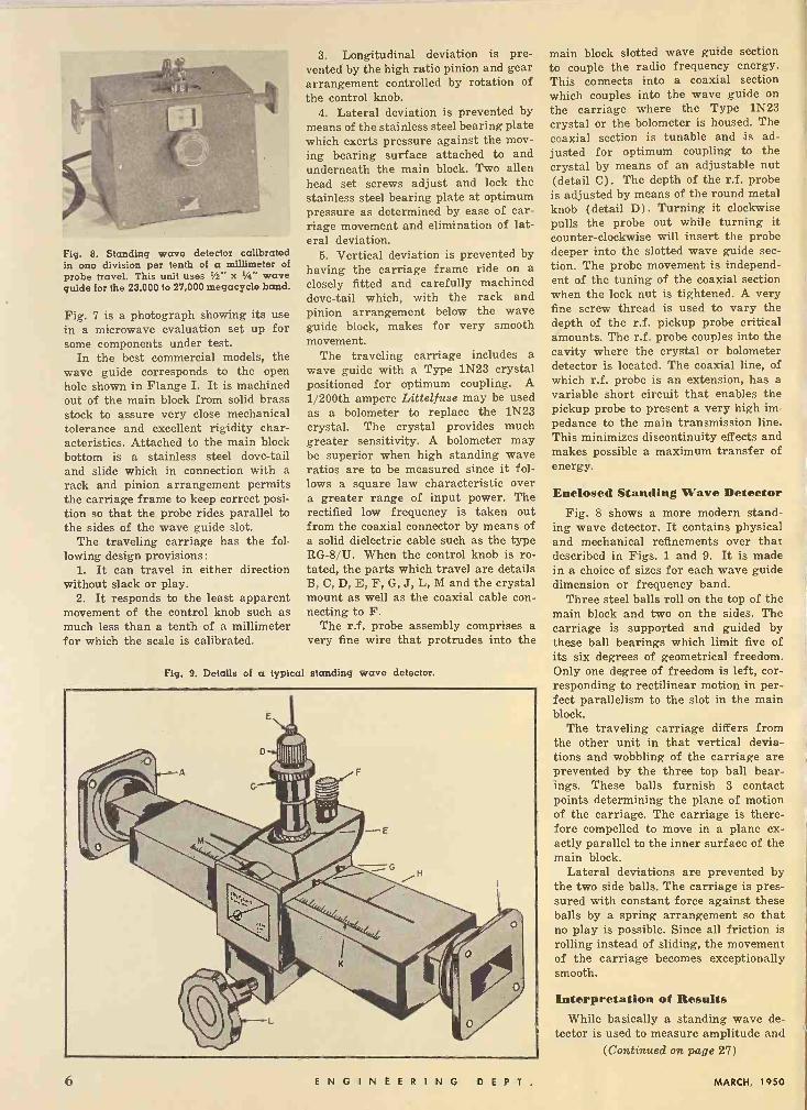
Fig. 8. Standing wave detector calibrated in one division per tenth of a millimeter of probe travel. This unit uses Vs" x 1/4" wave guide for the 23,000 to 27,000 megacycle band.
Fig. 7 is a photograph showing its use in a microwave evaluation set up for some components under test.
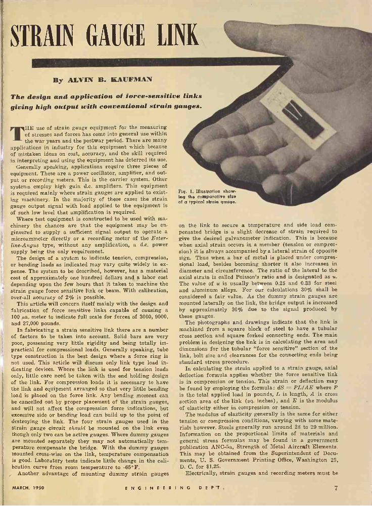
In the best commercial models, the wave guide corresponds to the open hole shown in Flange I. It is machined out of the main block from solid brass stock to assure very close mechanical tolerance and excellent rigidity char- acteristics. Attached to the main block bottom is a stainless steel dove -tail and slide which in connection with a rack and pinion arrangement permits the carriage frame to keep correct posi- tion so that the probe rides parallel to the sides of the wave guide slot.
The traveling carriage has the fol- lowing design provisions:
1. It can travel in either direction without slack or play.
2. It responds to the least apparent movement of the control knob such as much less than a tenth of a millimeter for which the scale is calibrated.
3. Longitudinal deviation is pre- vented by the high ratio pinion and gear arrangement controlled by rotation of the control knob.
4. Lateral deviation is prevented by means of the stainless steel bearing plate which exerts pressure against the mov- ing bearing surface attached to and underneath the main block. Two allen head set screws adjust and lock the stainless steel bearing plate at optimum pressure as determined by ease of car- riage movement and elimination of lat- eral deviation.
5. Vertical deviation is prevented by having the carriage frame ride on a closely fitted and carefully machined dove -tail which, with the rack and pinion arrangement below the wave guide block, makes for very smooth movement.
The traveling carriage includes a wave guide with a Type 1N23 crystal positioned for optimum coupling. A 1/200th ampere Littelfuse may be used as a bolometer to replace the 1N23 crystal. The crystal provides much greater sensitivity. A bolometer may be superior when high standing wave ratios are to be measured since it fol- lows a square law characteristic over a greater range of input power. The rectified low frequency is taken out from the coaxial connector by means of a solid dielectric cable such as the type RG -8/U. When the control knob is ro- tated, the parts which travel are details B, C, D, E, F, G, J, L, M and the crystal mount as well as the coaxial cable con- necting to F.
The r.f. probe assembly comprises a very fine wire that protrudes into the
Fig. 9. Details of a typical standing wave detector.
main block slotted wave guide section to couple the radio frequency energy. This connects into a coaxial section which couples into the wave guide on
the carriage where the Type 1N23 crystal or the bolometer is housed. The coaxial section is tunable and is ad- justed for optimum coupling to the crystal by means of an adjustable nut (detail C). The depth of the r.f. probe is adjusted by means of the round metal knob (detail D). Turning it clockwise pulls the probe out while turning it counter -clockwise will insert the probe deeper into the slotted wave guide sec- tion. The probe movement is independ- ent of the tuning of the coaxial section when the lock nut is tightened. A very fine screw thread is used to vary the depth of the r.f. pickup probe critical amounts. The r.f. probe couples into the cavity where the crystal or bolometer detector is located. The coaxial line, of which r.f. probe is an extension, has a variable short circuit that enables the pickup probe to present a very high im- pedance to the main transmission line. This minimizes discontinuity effects and makes possible a maximum transfer of energy.
Enclosed Standing Wave Detector Fig. 8 shows a more modern stand-
ing wave detector. It contains physical and mechanical refinements over that described in Figs. 1 and 9. It is made in a choice of sizes for each wave guide dimension or frequency band.
Three steel balls roll on the top of the main block and two on the sides. The carriage is supported and guided by these ball bearings which limit five of its six degrees of geometrical freedom. Only one degree of freedom is left, cor- responding to rectilinear motion in per- fect parallelism to the slot in the main block.
The traveling carriage differs from the other unit in that vertical devia- tions and wobbling of the carriage are prevented by the three top ball bear- ings. These balls furnish 3 contact points determining the plane of motion of the carriage. The carriage is there- fore compelled to move in a plane ex- actly parallel to the inner surface of the main block.
Lateral deviations are prevented by the two side balls. The carriage is pres- sured with constant force against these balls by a spring arrangement so that no play is possible. Since all friction is rolling instead of sliding, the movement of the carriage becomes exceptionally smooth.
Interpretation of Results While basically a standing wave de-
tector is used to measure amplitude and (Continued on page 27)
6 ENGINEERING D E P T. MARCH, 1950
STRAIN GAUGE LINK
By ALVIN B. KAUFMAN
The design and application of force -sensitive links giving high output with conventional strain gauges.
THE use of strain gauge equipment for the measuring of stresses and forces has come into general use within the war years and the postwar period. There are many
applications in industry for this equipment which because of mistaken ideas on cost, accuracy, and the skill required in interpreting and using the equipment has deterred its use.
Generally speaking, applications require three pieces of equipment. These are a power oscillator, amplifier, and out- put or recording meters. This is the carrier system. Other systems employ high gain d.c. amplifiers. This equipment is required mainly where strain gauges are applied to exist- ing machinery. In the majority of these cases the strain gauge output signal with load applied to the equipment is of such low level that amplification is required.
Where test equipment is constructed to be used with ma- chinery the chances are that the equipment may be en- gineered to supply a sufficient signal output to operate a
E! microammeter directly or a recording meter of the Ester - line -Angus type, without any amplification, a d.c. power supply being the only requirement.
The design of a system to indicate tension, compression, or bending loads as indicated may vary quite widely in ex- pense. The system to be described, however, has a material cost of approximately one hundred dollars and a labor cost depending upon the few hours that it takes to machine the strain gauge force sensitive link or beam. With calibration, over-all accuracy of 2% is possible.
This article will concern itself mainly with the design and fabrication of force sensitive links capable of causing a 100 µa. meter to indicate full scale for forces of 3000, 9000, and 27,000 pounds.
In fabricating a strain sensitive link there are a number of factors to be taken into account. Solid bars are very poor, possessing very little rigidity and being totally im- practical for compressional loads. Generally speaking, tube type construction is the best design where a force ring is not used. This article will discuss only link type load in- dicating devices. Where the link is used for tension loads only, little care need be taken with the end holding design of the link. For compression loads it is necessary to have the link and equipment arranged so that very little bending load is placed on the force link. Any bending moment can be cancelled out by proper placement of the strain gauges, and will not affect the compression force indications, but excessive side or bending load can build up to the point of destroying the link. The four strain gauges used in the strain gauge circuit should be mounted on the link even though only two can be active gauges. Where dummy gauges are mounted separately they may not automatically tem- perature compensate the bridge. With the dummy gauges mounted cross -wise on the link, temperature compensation is good. Laboratory tests indicate little change in the cali- bration curve from room temperature to -65°F.
Another advantage of mounting dummy strain gauges
Fig. 1. Illustration show- ing the comparative size of a typical strain gauge.
on the link to secure a temperature and side load com- pensated bridge is a slight decrease of strain required to give the desired galvanometer indication. This is because when axial strain occurs in a member (tension or compres- sion) it is always accompanied by a lateral strain of opposite sign. Thus when a bar of metal is placed under compres- sional load, besides becoming shorter it also increases in diameter and circumference. The ratio of the lateral to the axial strain is called Poisson's ratio and is designated as u. The value of u is usually between 0.25 and 0.33 for steel and aluminum alloys. For our calculations 30% shall be considered a fair value. As the dummy strain gauges are mounted laterally on the link, the bridge output is increased by approximately 30% due to the signal produced by these gauges.
The photographs and drawings indicate that the link is
machined from a square block of steel to have a tubular cross section and square forked connecting ends. The main problem in designing the link is in calculating the area and dimensions for the tubular "force sensitive" section of the link, bolt size and clearances for the connecting ends being standard stress procedure.
In calculating the strain applied to a strain gauge, axial deflection formula applies whether the force sensitive link is in compression or tension. This strain or deflection may be found by employing the formula: dS = PL/AE where P is the total applied load in pounds, L is length, A is cross section area of the link (sq. inches), and E is the modulus of elasticity either in compression or tension.
The modulus of elasticity generally is the same for either tension or compression conditions, varying with some mate- rials however. Steels generally run around 28 to 29 million. Information on the proportional limits of materials and general stress formulas may be found in a government publication ANC -5a, Strength of Metal Aircraft Elements. This may be obtained from the Superintendent of Docu- ments, U. S. Government Printing Office, Washington 25, D. C. for $1.25.
Electrically, strain gauges and recording meters must be
MARCH, 1950 ENGINEERING D E P T. 7
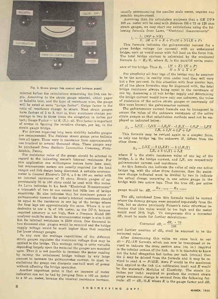
Fig. 2. Strain gauge link control and balance panel.
selected before the calculations concerning the link can be- gin. According to the strain gauge selected, either paper or bakelite base, and the type of resistance wire, the gauge will be rated at some "gauge factor". Gauge factor is the ratio of resistance change to strain. Most strain gauges have factors of 2 to 3, that is, their resistance change per- centage is two to three times the elongation in inches per inch; Gauge Factor = (d R,IR,) /dS. This factor is important of course in figuring the resistive change, per leg, in the strain gauge bridge.
For devices requiring long term stability bakelite gauges are recommended. The Baldwin strain gauge price bulletin lists all types. These vary in resistance from approximately one hundred to several thousand ohms. These gauges may be purchased from Baldwin Locomotive. Company, Phila- delphia, Penna.
The resistance value of the gauge should be selected in regard to the indicating meter's internal resistance. For this application one milliampere meters have been used, but microampere meters are usually required for the load ranges and link design being discussed. A suitable microam- meter is General Electric's DP -9, a 0 to 100 µa. meter with an internal resistance of 75 ohms. Strain gauges of ap- proximately 50 to 150 ohms could be used with this meter. As Laws indicates in his book "Electrical Measurements" a mismatch of two to one causes but little loss of bridge sensitivity. He also indicates that for maximum power or galvanometer current the meter's internal resistance should be equal to the resistance in one leg of the bridge where the four legs are approximately the same. Where it is not desirable to use a / of 1% meter, as the DP -9, because required accuracy is not high, then a Simpson Model 260 analyzer could be used. Its microammeter range is also 0-100 but its internal resistance is 2500 ohms. One thousand to two thousand ohm gauges would be required and the bridge supply voltage would be much higher than that required for lower ohmage gauges.
In any case the wattage capabilities of the different strain gauges regulates the maximum voltage that may be applied to the bridge. This wattage rating is quite variable depending largely upon the material the gauges are mounted upon. Thus it is not possible to increase the meter reading by raising the unbalanced bridge voltage by any large amount to increase the galvanometer current. In most in- stallations the gauge can dissipate one-half watt of power without affecting the bridge operation.
Another important point is that an increase of meter indication can not be had by jumping from a 100 µa. meter to a 50 µa. meter, because the internal resistance increase,
gauge would be: dR,- 2
The dR, calculated from this formula would be correct where the dummy gauges were mounted separately from the link, but as shown previously Poisson's ratio otherwise in- dicates that this value would be too high and the meter would read 30% high. To compensate this a corrected dR, must be made for further calculations:
Corrected dR, = dR, 70 100
and further mention of dR, shall be assumed to be the corrected value. After determining this value we come back to our
dS = PL/AE formula which can now be transposed or re- vised to indicate the cross section area (sq. in.) required in the tubular section of the link. As it is desirable to know not the total elongation but inches per inch (strain) then the L may be deleted from the formula and it may be re- vised to read A = P/dSE. Here P would be the maximum load, applied to the link (i.e. calibration load) and E would be the material's Modulus of Elasticity. The strain (in inches per inch) required to produce the correct strain gauge resistance change is secured from the following for- mula: dS = dR,/R,K where K is the gauge factor and dR,
usually accompanying the smaller scale meter, negates any possible improvement.
Assuming then for calculation purposes that a GE DP -9 100 µa. meter will be used with Baldwin SR -4 75 or 120 ohm strain gauges, we may start our calculations using the fol- lowing formula from Laws, "Electrical Measurements":
la (MP + NX ) R, (M+N+X +P) (M -FN) (X +P)
This formula indicates the galvanometer current for a given bridge voltage (or current) with an unbalanced bridge, such as would occur with full load on the force link. The total bridge current is calculated by the condensed formula Is = EB/R, where R, is the parallel series resist-
ance of the bridge. Thus R, _ (M -E X) (N + P) M+N±X ±P
For simplicity all four legs of the bridge may be assumed to be the same; in reality even under load they will vary but a few per -cent. In this situation with four similar legs, all of the above formulas may be dispensed with, the total bridge resistance always being equal to the resistance of one leg. Assuming a 10 volt bridge supply and determining the bridge current would leave only one unknown, the value of resistance of the active strain gauges or conversely (if this were known) the galvanometer current.
The galvanometer current formula can be transposed to secure the value of the unknown resistance of the active strain gauges so that substitution methods need not be em- ployed as indicated below:
RM - I bNX - I,NX - I,R,N - I,R°X - I,R,P - I,PX I,R, + I,N + I,P + I,P
This formula may be revised again to a simpler form, as only one bridge leg, the unknown M, differs from the other three:
Rbr-I,XX-2 (I,XX) -3 (I,R,X) I,R, + 2 (I,X) + IbX
where X is the static resistance value of one leg of the bridge, Ib is the bridge current, and I,R, are respectively galvanometer current and resistance.
As this formula can indicate the value of only one active bridge leg, with the other three dummies, then the resist- ance change indicated must be divided by two to indicate the actual change occurring in one active gauge in the bridge with two active legs. Thus the true dR, per active
R,r static --Rif loaded
8 ENGINEER! N G DEPT.MARCH. 1950
is the change in resistance of one of the strain gauges, as previously calculated. R, is the nominal resistance of the gauge. There is little need to note that regardless of the length of the strained area, the strain remains the same, and that the tubular section of the link can be made any length desirable.
Now that the area of the tubular section of the link has been determined it is a comparatively simple matter to calculate its ID and OD. For the design shown in the drawing it was thought advisable to use a % inch ID which could be drilled conveniently and then machine the outside. The outside diameter for the given area may be found with the
following formula: OD = Y
area of ID + Link area .7864
where area may be found with: Area = .7854d'. The material the link may be machined from may be
selected from ANC -6a or other references. It must have a proportional stress loading in pounds per square inch higher than the stress placed on the link so as to not cause any permanent set in the material and consequent change in calibration, with full load. Knowing the smallest cross section area of the link and the pounds applied, the stress on the material may easily be determined. This would be: Stress (psi) _ [Applied lbs (to link) ]/[Sq. inches (of link) ]. Any steel of any heat treat can be used so long as its Modulus of Elasticity is that of the value used in the calculations. Therefore if it is necessary to change steels because of exceeding the proportional limits it would not be necessary to re -calculate if the new steel or heat treatment did not affect the E.
When the link is machined it is necessary to hold the tolerances quite close if accurate results are to be achieved. A variation of plus or minus one thousandth of an inch on these link diameters can cause the calculated results to differ from empirical tests by several per -cent. It is preferable to allow + or - tolerances in a direction that would, were error present, make the link area smaller rather than larger.
In considering the design of the link it is better to err in the direction of excessive sensitivity than lower sensi- tivity. It is always practical to shunt the meter down and secure full scale indication, but it is not always possible to raise the meter reading. Either of these two conditions can be corrected to a certain amount by varying the bridge supply voltage.
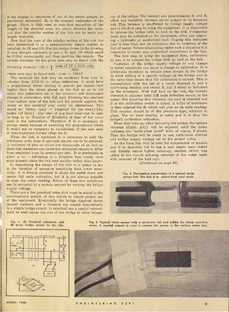
There are a few practical notes that must be added to the constructional section of this article to insure proper use of the equipment. Electrically the bridge diagram shows several resistors and a rheostat not needed theoretically in a simple bridge circuit. In practical use a special network must be used across one side of the bridge to allow balanc-
Fig. 4. (A) Practical schematic and (B) basic bridge circuit for the link.
ing of the bridge. The resistor and potentiometer R, and R. allow any variation between strain gauges to be balanced out. This balance is unaffected by bridge supply voltage and is the first step in using the equipment. It is imperative to balance the bridge with no load on the link. Frequently loads may be indicated on the equipment, after just remov- ing a hydraulic or mechanical load. Usually this indicated load is true load, not an indication due to hystersis of the link of meter. Before rebalancing under such a situation it is necessary to loosen any mechanical connections to the link.
The first step in using the equipment then, calibration or use, is to balance the bridge with no load on the link.
Variation of the bridge supply voltage or any change in meter sensitivity can cause a change in calibration. It is preferable therefore to include some circuit in the bridge to allow setting of a specific voltage on the bridge and at the same time insure that the calibration is correct. This is accomplished with the aid of a series rheostat R. and a calibrating resistor and switch R. and S wired as indicated on the schematic. With full load on the link, the battery rheostat is adjusted until full scale deflection occurs on the meter. Not touching this rheostat, the load is removed and S or the calibration switch is closed. A value of resistance is then selected for R. which will give an on scale reading. This resistor should be of the precision type, soldered in place. The on scale reading is noted and it is then the bridge's calibration indication.
From that time on, after balancing the tridge, the battery rheostat (Calib. Adj.) will be adjusted until the meter indicates the "calibration point" with, of course, S closed. Then the bridge will be ready to use, calibration checked and bridge supply voltage set to the proper value.
As the force link may be used for compression or tension and it is desirable not to use a zero center scale meter and thereby secure higher accuracy, another switch was added to the circuit allowing reversal of the meter leads with reversal of the load sign.
(Continued on page 26)
Fig. 3. Mechanical construction of a typical strain gauge link. The link is n shined from solid stock.
Fig. 5. Typical strain gauge with a protective felt pad hiding the strain sensitive wires. A special cement is used to cement the gauge to the surface under test.
MARCH, 1950 ENGINEERING DEPT. 9

U.H.F. TV
CONVERTER DESIGN
By
NICHOLAS T. SIMOPOULOS
Design and development of a tuner or converter for use in the u.h.f. range of 450 to 900 megacycles.
WITH the forthcoming allocation of television channels between 450 to 900 megacycles, there
arises the problem of continuous track- ing for television "front ends" at the above frequencies. This article describes a patented tuning unit which covers this band.
The author had worked with wide range tuners during World War II in the Special Projects Laboratory at Wright Field, Dayton, Ohio for pan- oramic adapter use. As a result of a study of the problem, a tuner was de- veloped which gave a tuning ratio of more than four to one.
The tuner described in this article
800
700
500
400
300
is a prototype of the one to be put into production. The tuning unit has numer- ous possibilities, finding uses in fre- quency meters, signal generators, and frequency modulated altimeters, in ad- dition to its use in the r.f. and local oscillator sections of television receivers.
A purely mathematical treatment is very difficult due to the fact that induc- tance and capacity both change with rotation of the rotor. The range of the tuner is covered in a 90° angular change of the rotor. An important advantage is its simplicity of construction. There are no wiping contacts.
A typical tuner installation in a con- verter is shown in Fig. 6. A tuner for a
Fig. 2. Curve showing change in oscillator frequency vs. angular position of rotor. Effects of added capacity are also indicated.
CHANGE VERSUS ROTOR
I IN OSCILLATOR ANGULAR
AND ADDED
I
FREQUENCY POSITION OF CAPACITY
I
Ac= 3 Puld.
A, .0
Ác4.5 uuld.- -
A,1.8 Plad.
HIGH RANGE TUNER
LOW RANGE TUNER
ROTATION IN DEGREES 70 80
Fig. 1. A tuner of the type described in this article for use in a signal generator.
signal generator use is shown in Fig. 1. A breakdown of the parts used in the tuner of Fig. 1 is shown in Fig. 7. A curve showing changes in frequency ver- sus angular position of the rotor is shown in Fig. 2.
The tuner used with the oscillator of the converter shown in Fig. 1 measures 3% inches over-all with an opening of 5AG" by 13 " on either side of the center web of the rotor. The outside diameter of the rotor is %", and the spacing of the rotor to stator is 0.007" on the radius.
A typical circuit diagram is shown in Fig. 3B. A 6F4 type tube was used in the oscillator circuit and worked rather well in this application with some exceptions. Planar type electrodes lend themselves to easy mounting and low lead inductances. A type 5767 "rocket" tube was used on one tuner but due to its cathode construction and size, did not prove successful. A planar type tube with straps brought out at the tube electrodes (to reduce lead inductance) would prove useful in conjunction with these tuners. However, as mentioned before, the 6F4 tube gives satisfactory results.
Tuners may be made to track very closely by adjusting the shunting capac- ity of the tuner and if necessary the angular position of the rotor. The tuner has a bandwidth of approximately 5.1 mc. Experimental measurements give a Q of 70 at 360 mc.
Development models of the tuners are available at present for experimental use only.
10 ENGINEERING D E P T. MARCH, 1950
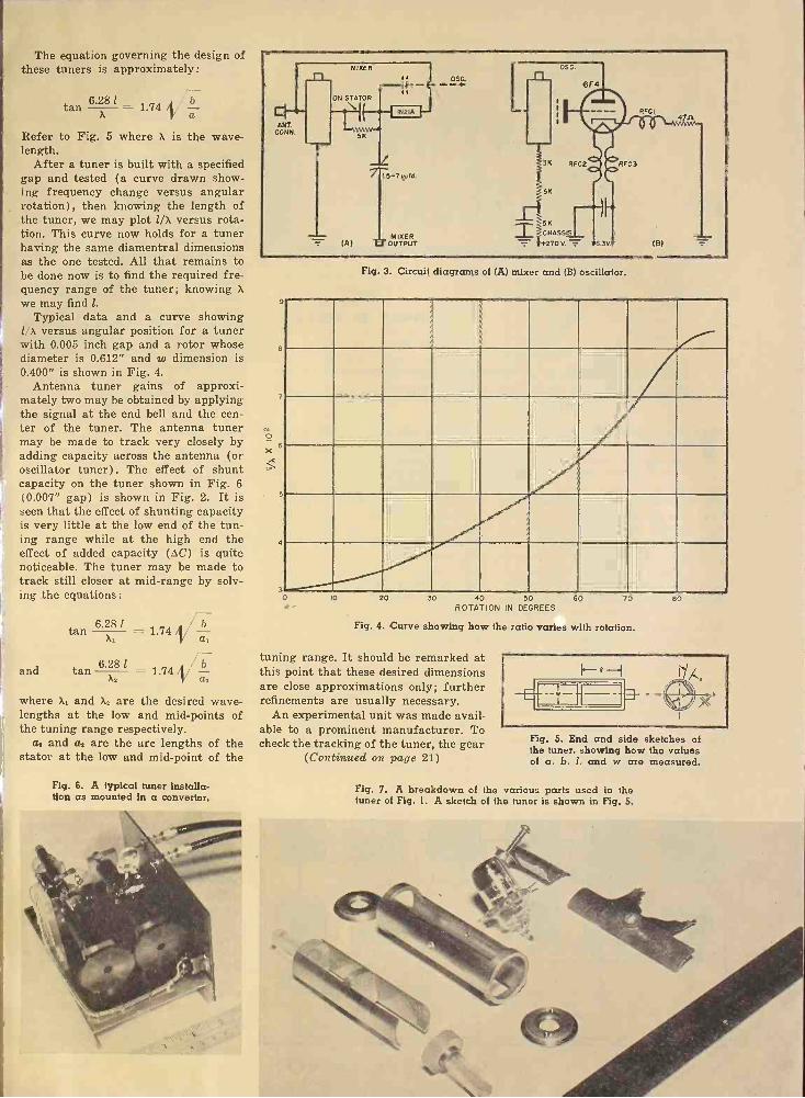
The equation governing the design of these tuners is approximately:
6.281 tan = 1.74 it
Refer to Fig. 5 where X is the wave- length.
After a tuner is built with a specified gap and tested (a curve drawn show- ing frequency change versus angular rotation), then knowing the length of the tuner, we may plot 1/a versus rota- tion. This curve now holds for a tuner having the same diamentral dimensions as the one tested. All that remains to be done now is to find the required fre- quency range of the tuner; knowing X
we may find 1.
Typical data and a curve showing 1/x versus angular position for a tuner with 0.005 inch gap and a rotor whose diameter is 0.612" and w dimension is 0.400" is shown in Fig. 4.
Antenna tuner gains of approxi- mately two may be obtained by applying the signal at the end bell and the cen- ter of the tuner. The antenna tuner may be made to track very closely by adding capacity across the antenna (or oscillator tuner). The effect of shunt capacity on the tuner shown in Fig. 6 (0.007" gap) is shown in Fig. 2. It is seen that the effect of shunting capacity is very little at the low end of the tun- ing range while at the high end the effect of added capacity (AC) is quite noticeable. The tuner may be made to track still closer at mid -range by solv- ing the equations:
tan 6.X8 l 1.74 N a b
and tan 6.81 1.74
where X, and X, are the desired wave- lengths at the low and mid -points of the tuning range respectively.
a, and a, are the arc lengths of the stator at the low and mid -point of the
Fig. 6. A typical tuner installa- tion as mounted in a converter.
9
e
7
ó 6
5
4
Fig. 3. Circuit diagrams of (A) mixer and (B) oscillator.
z
3 o IO 20 30 40 50 60
ROTATION IN DEGREES 70
Fig. 4. Curve showing how the ratio varies with rotation.
tuning range. It should be remarked at this point that these desired dimensions are close approximations only; further refinements are usually necessary.
An experimental unit was made avail- able to a prominent manufacturer. To check the tracking of the tuner, the gear
(Continued on page 21)
80
Fig. 5. End and side sketches of the tuner, showing how the values of a, b, 1, and w are measured.
Fig. 7. A breakdown of the various parts used in the tuner of Fig. 1. A sketch of the tuner is shown in Fig. 5.
\ \ CRYSTAL
SAVERS
By HAROLD E. BRYAN
Several methods of obtaining crystal control of a large number of channels using only a few crystals.
THE problem of frequency stabil- ity in transmitters and receivers has become increasingly impor-
tant in the past few years. The tend- ency toward the use of higher frequen- cies, together with the increase in the number of occupied channels, has made the need for stability combined with flexibility more and more apparent. For example, in one of the v.h.f. bands there are 280 channels, any one of which must be instantly available to the receiver operator. These channels are spaced at intervals of 100 kilocycles, which re- quires high stability and makes crystal control almost mandatory.
Up until the last few years it has been common practice to obtain the nec- essary stability by means of low fre- quency crystals, multiplying to the desired output frequency. This works fine from the standpoint of stability, but leaves much to be desired in versa- tility. If operation is required on six channels, six crystals are required. This
is not too difficult a problem up to ten or fifteen channels, but is impracticable when operation is necessary on one hun- dred or more channels. Not only would the large number of crystals be expen- sive and space consuming, but there is not an unlimited supply of natural quartz suitable for manufacture of the crystals indefinitely.
In order to get around this difficulty, the so-called frequency synthesizers, or "crystal savers", have been developed. By means of these circuits, large num- bers of crystal controlled channels may be obtained with the use of a relatively few crystals. The chief disadvantage lies in the fact that in some cases very complex circuits are required. In many cases, however, they may be relatively simple and inexpensive. Amateurs in particular should be interested in the application of crystal savers to their problems.
Actually, there is nothing basically new and startling about frequency syn-
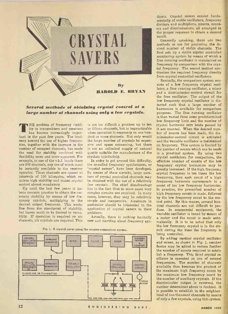
Fig. L A crystal saver using the counter -comparison system.
CRYSTAL OSCILLATOR FREQUENCY
CRYSTAL OSCILLATOR FREQUENCY.
HARMONIC GENERATOR
HARMONIC îENERATOR
O RECEIVER OR TRANSMITTER
MIXER I - VARIABLE
SCILLAToe
FILTER
-1
MISER DISCRIM- INATOR
a COUNTER
CONTROL CIRCUIT
TUNING
T ® 1223911 'MOTOR
T- 7- L - -J
CRYSTAL OSCILLATOR
._ a
I (\
thesis. Crystal savers consist funda- mentally of stable oscillators, frequency dividers and multipliers, mixers, count- ers and discriminators, all arranged in the proper sequence to obtain a desired result.
Generally speaking, there are two methods in use for producing the de- sired number of stable channels. The first sets up a stable crystal controlled monitoring system by means of which a free running oscillator is maintained on frequency by comparison with the crys- tal frequency. The second method syn- thesizes the required frequency directly from crystal controlled oscillators.
Basically, the comparison system con- sists of a low frequency crystal oscil- lator, a free running oscillator, a mixer and a discriminator -control circuit for the free oscillator. The output of the low frequency crystal oscillator is dis- torted such that a large number of harmonics is available for comparison purposes. The free running oscillator is then varied from some predetermined low frequency limit and the number of crystal harmonic zero beats passed by it are counted. When the desired num- ber of counts has been made, the dis- criminator -control circuit is activated and the variable oscillator is maintained on frequency. This system is limited by the number of counts which can be made in a practical system. By using two crystal oscillators for comparison, the effective number of counts of the low frequency crystal harmonics may be greatly increased. If the high frequency crystal frequency is ten times the low frequency, then each count of a high frequency harmonic corresponds to a count of ten low frequency harmonics. In practice, the prescribed number of high frequency counts is made, followed by the low frequency count to the con- trol point. By this means, several hun- dred channels are not difficult to pro- duce. In commercial equipment, the variable oscillator is tuned by means of a motor and the count is made auto- matically. It is to be noted that only the low frequency crystal is in the cir- cuit during the time the frequency is being controlled.
By adding another crystal oscillator and mixer, as shown in Fig. 1, another factor may be added to reduce further the number of counts required to estab- lish a frequency. This third crystal os- cillator is operated on one of several frequencies. The number of channels available then becomes the product of the maximum high frequency count by the maximum low frequency count by the number of auxiliary crystals. If the discriminator output is reversed, the number determined above is doubled. It is possible to establish in the neighbor- hood of one thousand channels by means of only a few crystals, using this system.
12 ENGINEERING D E P T. MARCH, 1950
i
One difficulty with this type of circuit is that all control frequencies are pres- ent at all times. Thus any disturbance which could cause a change in variable oscillator frequency greater than the difference between harmonics would cause the control to take place on an adjacent channel. When this occurs, there is no indication that it has hap- pened, with the resulting improper operation and consequent confusion.
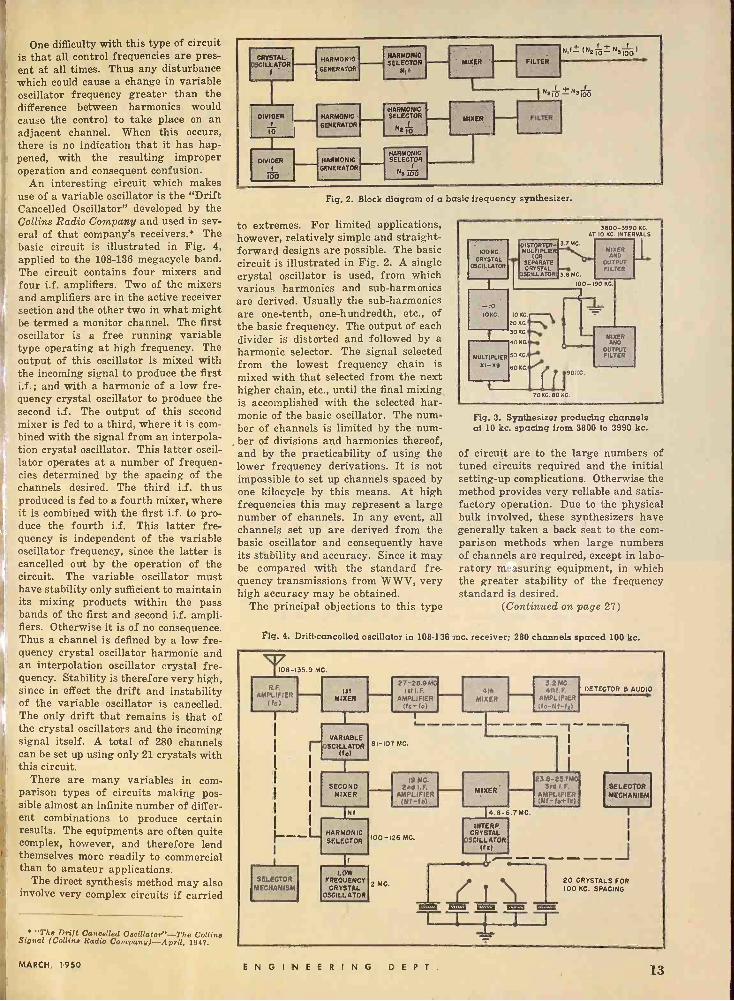
An interesting circuit which makes use of a variable oscillator is the "Drift Cancelled Oscillator" developed by the Collins Radio Company and used in sev- eral of that company's receivers.* The basic circuit is illustrated in Fig. 4, applied to the 108-136 megacycle band. The circuit contains four mixers and four i.f. amplifiers. Two of the mixers and amplifiers are in the active receiver section and the other two in what might be termed a monitor channel. The first oscillator is a free running variable type operating at high frequency. The output of this oscillator is mixed with the incoming signal to produce the first i.f.; and with a harmonic of a low fre- quency crystal oscillator to produce the second i.f. The output of this second mixer is fed to a third, where it is com- bined with the signal from an interpola- tion crystal oscillator. This latter oscil- lator operates at a number of frequen- cies determined by the spacing of the channels desired. The third i.f. thus produced is fed to a fourth mixer, where it is combined with the first i.f. to pro- duce the fourth i.f. This latter fre- quency is independent of the variable oscillator frequency, since the latter is cancelled out by the operation of the circuit. The variable oscillator must have stability only sufficient to maintain its mixing products within the pass bands of the first and second i.f. ampli- fiers. Otherwise it is of no consequence. Thus a channel is defined by a low fre- quency crystal oscillator harmonic and an interpolation oscillator crystal fre- quency. Stability is therefore very high, since in effect the drift and instability of the variable oscillator is cancelled. The only drift that remains is that of the crystal oscillators and the incoming signal itself. A total of 280 channels can be set up using only 21 crystals with this circuit.
There are many variables in com- parison types of circuits making pos- sible almost an infinite number of differ- ent combinations to produce certain results. The equipments are often quite complex, however, and therefore lend themselves more readily to commercial than to amateur applications.
The direct synthesis method may also involve very complex circuits if carried
"The Drift Cancelled Oacillator"-The Collins Signal (Collins Radio Company)-Agril, 1947.
CRYSTAL ILL ATOR
DIVIDER
00
HARMONIC
GENERATOR
HARMONIC
GENERATOR
HARMONIC GENERATOR
HARMONIC SELECTOR
NI f
HARMONIC SELECTOR
N210
HARMONIC SELECTOR
N3100
FILTER
MISER
Fig. 2. Block diagram of a basic frequency synthesizer.
to extremes. For limited applications, however, relatively simple and straight- forward designs are possible. The basic circuit is illustrated in Fig. 2. A single crystal oscillator is used, from which various harmonics and sub -harmonics are derived. Usually the sub -harmonics are one -tenth, one -hundredth, etc., of the basic frequency. The output of each divider is distorted and followed by a harmonic selector. The signal selected from the lowest frequency chain is mixed with that selected from the next higher chain, etc., until the final mixing is accomplished with the selected har- monic of the basic oscillator. The num- ber of channels is limited by the num- ber of divisions and harmonics thereof, and by the practicability of using the lower frequency derivations. It is not impossible to set up channels spaced by one kilocycle by this means. At high frequencies this may represent a large number of channels. In any event, all channels set up are derived from the basic oscillator and consequently have its stability and accuracy. Since it may be compared with the standard fre- quency transmissions from W W V, very high accuracy may be obtained.
The principal objections to this type
AT
3.7MC.
3000-3990 10 RC INTERVALS
KC
OtsTORTER- 100 KC
CRYSTAL OSCILLATOR
MULTIPLIER IOR
SEPARATE CRYSTAL -
MIXER AND
OUTPUT FILTER
05GILL ATOR 3.6MC.
t 100 -190 KC.
10
IDES. IOW .
20KGA-N, 3oK0.04...
MI ER 40KGe- AND
OUTPUT MULTIPLIER 30KC.e FILTER
XI -x9
70K0. 60.15.
Fig. 3. Synthesizer producing channels at 10 kc. spacing from 3800 to 3990 kc.
of circuit are to the large numbers of tuned circuits required and the initial setting -up complications. Otherwise the method provides very reliable and satis- factory operation. Due to the physical bulk involved, these synthesizers have generally taken a back seat to the com- parison methods when large numbers of channels are required, except in labo- ratory m: .surfing equipment, in which the greater stability of the frequency standard is desired.
(Continued on page 27)
Fig. 4. Drift -cancelled oscillator in 108-136 mc. receiver; 280 channels spaced 100 kc.
108-135.9 MC
27-28.9 MG 3.2 MC. R.F. Ist Ist I.F. 41h 4th). F. DETECTOR 8 AUDIO
AMPLIF,ER MIXER AMPLIFIER MIXER AMPLIFIER Id) (fc - fol Ifc-Nf-I,)
SELECTOR MECHANISMS
VARIABLE r OSCILLATOR Ito)
SECOND MIXER
'NI
HARMONIC SELECTOR
LOW FREOUENCY
CRYSTAL OSCILLATOR
-----,----1 81-107 MC.
19 MC. 23.8-257M) 2nd I.F. H 3rd 1 F. SELECTOR
MIXER AMPLIFIER (Nf-f o)
AMPLIFIER (Nt- for fx)
MECHANISM
100-126 MC.
2 MC.
a.8-6.7 MC.
INTERP CRYSTAL
OSCILLATOR (rX) 1
_Z1 ® ® ® ® ® T- 20 CRYSTALS FOR 100 KC. SPACING
MARCH, 1950 ENGINEERING D E P T. 13

MICROWAVE
TRANSMISSION
LIN[S By J. RACKER
Federal Telecommunication Laboratories
Fig. 1. Typical r.f. terminal of micro- wave link showing transmission line connections. Outputs of individual units are connected to a flexible, dielectric coaxial cable, which in turn is connected to air -dielectric lines.
A discussion of methods of transmitting microwave energy, with particular emphasis on wave guides.
TRANSMISSION of energy at mi- crowave frequencies is effected through the propagation of elec-
tromagnetic waves. Transmission lines, used at these frequencies, therefore function primarily to guide these elec- tromagnetic waves and the study of these lines is closely linked with wave theory. As a matter of fact, at the higher frequencies (about 7000 mc. and above) it is possible to confine micro- waves to such a narrow beam that transmission of energy from one point to another can be achieved efficiently without the use of physical lines. This article will be concerned with the prac- tical problem of how to select the op- timum transmission line system for any given application. Sufficient theory will be introduced to enable the engineer to understand the reason for the choices involved.
As indicated in the introductory arti- cle to this series, "Microwave Tech- niques", two basic types of transmission lines are used, i.e., coaxial lines and wave guides. Coaxial lines are nor- mally used for frequencies up to about 2500 mc. This figure is based upon a number of factors including size, atten- uation, and cost of the lines. It will be shown that the size of the wave guides (such as those shown in Fig. 4) varies inversely with frequency (hence they are employed almost universally for fre- quencies above 2500 mc.) while the size of a coaxial line increases with fre- quency for constant attenuation, all other factors remaining equal. At about 2500 mc. the size of the coaxial line is increased to the point that it becomes comparable to a wave guide designed for this frequency, for equivalent line attenuation.
At microwaves, transmission lines may be used for one of two functions. The first is the one normally associated with transmission lines and that is for the transfer of energy from one point to another. Sections of these lines can be used to obtain inductive and capaci- tive reactances, transformers, and fil- ters. This aspect will be considered separately in the next article. This arti- cle will cover the use of lines for the point-to-point transmission of micro- wave power such as would be required to connect transmitter to antenna, or antenna to receiver.
Coaxial Lines
Coaxial lines are familiar to most en- gineers since they have been used exten- sively in FM and television as well as other u.h.f. applications. Since they are used extensively, a large number of standard type cables is available at rea- sonable cost. Consequently coaxial cable is used whenever possible. It is impor- tant to understand the relationship be- tween size, attenuation, power ratings, characteristic impedance, etc., of these cables, since in many cases the informa- tion supplied by the manufacturer will cover the u.h.f range only (up to about 500 mc.) and it will be necessary for the microwave engineer to estimate the line characteristics at higher frequencies.
There are two sources of power loss in a microwave line. One is due to the line attenuation and the other to mis- match either between line and load or as a result of impedance variation within the line. The attenuation of a coaxial line is given by':
ar=a + ad 0.435(Rdr
+D3) Jf + 2.78 Jk pf . (1)
where ar a,
a4
is the total attenuation is the attenuation due to the high frequency resistance of the conductors is the attenuation due to the dielectric losses
14 ENGINEERING D E P T. MARCH, 1950
R, & R: are equal to the ratios of the d.c. resistance of con- ductor used to the d.c. re- sistance of copper
Z. is the characteristic imped- ance of the line
ci is the diameter of the inner conductor
D is the diameter of the outer conductor
f is the frequency in mc. p is the power factor of the
dielectric k is the dielectric constant
The first part of Eqt. (1) is the at- tenuation of the line caused by the high frequency resistance of the conductors, and as indicated in this equation, the condúctor attenuation increases as the diameters d and D decrease, and as the square root of frequency. In order to keep the attenuation constant as the frequency increases, it is therefore nec- essary to increase the conductors' diam- eters. It should be noted that the ratio of Did must be kept constant for a given characteristic impedance, and that the inner conductor, having the smaller diameter, contributes a major part of the conductor losses.
The sécond part of Eqt. (1) repre- sents losses due to the dielectric. In the u.h.f. region the conductor losses are the major part of the total line attenua- tion. However, since the dielectric losses increase directly as the frequency, in- stead of as the square root of frequency, a point will be reached in the microwave band where the dielectric losses become
i comparable and then exceed the con- ductor attenuation. To reduce the dielec- tric loss, the dielectric constant, k, can be decreased. This is done by using air, rather than the usual polyethylene, as the dielectric. Air dielectric lines should
, be used only when absolutely necessary t since they are more expensive, more dif-
ficult to handle (most are rigid instead of flexible), introduce mismatch losses due to discontinuities, and require spe- cial dehydrating and constant pressure apparatus to maintain uniform opera- tion for all ambient conditions.
The power rating of a polyethylene dielectric cable is a function of the max- imum temperature which the insulation can safely withstand. The power -han- dling capability of the cable is limited by the rate at which the cable can dis- sipate the heat generated by conductor and dielectric losses and is therefore in- versely proportional to the line attenua- tion. For the purposes of this article, the following relation between power rating and attenuation is sufficient:
P = K,Iar (2) where K. is a constant for any given cable.
Knowing the power rating and atten- uation of a cable for any u.h.f. fre-
quency, it is readily possible through the use of Eqts. (1) and (2) to estimate its power rating at any desired micro- wave frequency.
Losses Due to Mismatch It has been shown in the previous
article that when a line is terminated in its characteristic impedance, no re- flections occur, and all the power trans- mitted down the line is absorbed by the load. (Of course loss in power will re- sult if the generator is not matched to the load, but this factor is not due to the transmission line. The assumption will be made that the generator is matched to the line.) However if the load is not equal to the characteristic impedance, reflections occur-setting up standing waves-and losses due to mismatch re- sult.
The ratio of reflected to incident waves for any arbitrary load Z, is given by:
V: Z,/Z.-1 V, Z,/Z, + 1
where V. is reflected wave voltage, and V, incident wave voltage. Since the load may be complex, this equation may con- tain complex quantities and the ratio of V:/V: will not only give the relative magnitude but also the relative phase between the two quantities.
As power varies with the square of voltage, the impedance being held con- stant, the per -cent power reflected from an arbitrary load is :
% power reflected = (ÿl) X 100.. (4)
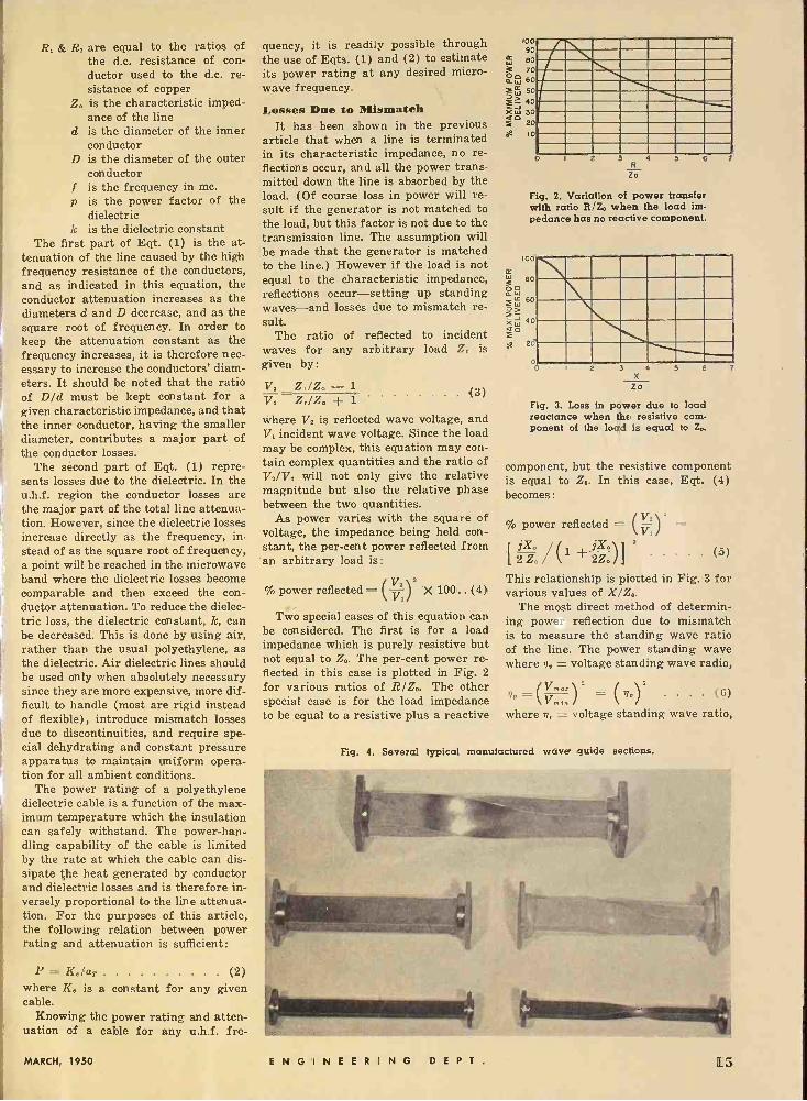
Two special cases of this equation can be considered. The first is for a load impedance which is purely resistive but not equal to Zo. The per -cent power re- flected in this case is plotted in Fig. 2 for various ratios of RIZ0. The other special case is for the load impedance to be equal to a resistive plus a reactive
(3)
100 90
m 60 3 70 áW 60
W 50
J40 Xt.: 30 0
20
at to
o 2 3 4
Zó
S 6
Fig. 2. Variation of power transfer with ratio R/Zo when the load im- pedance has no reactive component.
100
,r 60
áw w 60
xw 40 o
20
0 0
7
3 4 X zo
Fig. 3. Loss in power due to load reactance when tilt, resistive com- ponent of the load is equal to Zo.
component, but the resistive component is equal to Zo. In this case, Eqt. (4) becomes :
% power reflected = (V=) Vi
[241(1o/ \1 + Zo/111 3
This relationship is plotted in Fig. 3 for various values of X/Z,,.
The most direct method of determin- ing -powe-- reflection due to mismatch is to measure the standing wave ratio of the line. The power standing wave where n, = voltage standing wave radio,
(5)
Vmax
P (Vmt)Z = (+/v)Z . . . . (6)
where n, = voltage standing wave ratio,
Fig. 4. Several typical manufactured wave guide sections.
MARCH, 1950 ENGINEERING D E P T. 15
100
50
10
5
5 10 50 100 500 IK r15 STANDING WAVE RATIO IN POWER
Fig. 5. Per -cent power reflected vs. standing wave ratio in power.
Fig. 6. Undercutting center conductor where bead support is inserted to main- tain constant characteristic impedance.
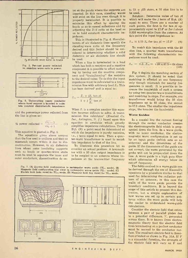
and the percentage power reflected from the line is given as:
% power reflected - Vi-- 1 1.64, + 1
. (7)
This equation is plotted in Fig. 5. The equations given above assume
that the line used is uniform and that no mismatch occurs within it due to dis- continuities. However, in air dielectric lines where some insulating supports such as beads or quarter -wave stubs must be used to separate the inner and outer conductors, discontinuities do ex-
ist at the points where the supports are inserted. In this case, standing waves will exist on the line even though it is properly terminated. It is possible to minimize this effect by spacing the beads so as to cancel reflections and by adjusting the D/d ratio at the bead so
as to hold constant characteristic im- pedance.
This is illustrated in Fig. 6. Manufac- turers of air dielectric lines specify the standing -wave ratio at the frequency desired and this factor should be con- sidered in determining whether a solid dielectric or air dielectric line should be used.
When a line is terminated in a load which has both a resistive and a reactive component it is possible to effect match- ing by tuning out the reactive compo- nent and "transforming" the resistive to the desired value. To do this the input impedance must be calculated to a trans- mission line with arbitrary load Z,. This has been derived' and is equal to :
Z, jZ° tan ßl - 1 jZ - tanßl
(8)
When Z, is a complex number this equa- tion becomes difficult to solve. A trans- mission line calculator' (Emeloid Co. Inc., Arlington, N. J.) based upon this equation is available which greatly simplifies impedance calculations. Using Eqt. (8) a point must be determined at which the impedance is purely resistive, i.e., j term equal to zero. Then a quar- ter -wave transformer is used to match this impedance to that of the line.
To illustrate this procedure let us consider an actual problem. A transmit- ter with a 50 ohm output impedance is to be coupled to an antenna whose im- pedance at the transmitter frequency
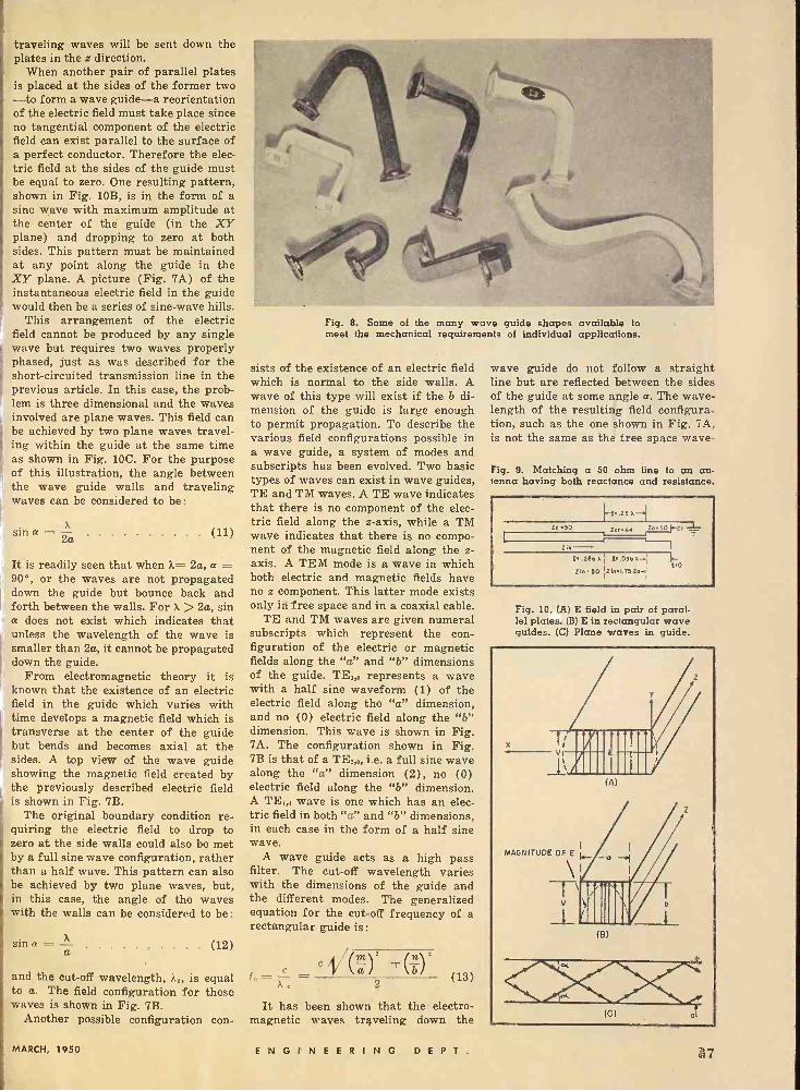
Fig. 7. (A) Electric field configuration in rectangular wave guide (TE0 mode). (B) Magnetic field configuration (top view) in rectangular wave guide (TE° mode). (C) Electric field (side view) for TE..o mode. (D) Magnetic field (top view) for TE_,o mode.
I [ i 1
is '75 j25 ohms, a 50 ohm line is to be used.
Solution: Determine value of tan ßl which will make the j term of Eqt. (8) equal to zero. There are a number cf such points, the first is for tan ßl ap- proximately equal to 17.5° or for l about 0.036 wavelengths from the antenna. At this point the input impedance is :
Z,° 1.75 Z. for tan ßl = 17.5° . (9)
To match this impedance with the 50 ohm line, a quarter wave transformer with the following characteristic im- pedance must be used:
Z°, = 27, _ 50 X 87.5 = 64 ohms (10)
Fig. 9 depicts the matching section of this system. It should be noted that matching is effected at one frequency only though mismatch for nearby fre- quencies is small. It is possible to in- crease the bandwidth of such a system by using two quarter -wave transformers and matching in steps. For example, one transformer would bring the 50 ohm impedance up to 68 ohms, the second to 87.5 ohms. The smaller the impedance steps, the broader the bandwidth.
Wave Guides In a coaxial line the current flowing
through the center conductor creates the electromagnetic field which is prop- agated down the line. In a wave guide, with no inner conductor, the electro- magnetic wave configuration is set up by an input probe (which acts as an antenna) and the dimensions of the guide. If the dimensions of the guide are not correct, the wave generated by the probe will not be propagated down the line. A wave guide is a high pass filter which attenuates all energy below its cut-off frequency.
The fields evolved in a wave guide can be derived through the use of Maxwell's equations by a procedure similar to that used for determining the radiation pat- tern of an antenna; in this case the walls of the wave guide provide the boundary conditions. It is beyond the scope of this article to present this der- ivation, but a simple explanation of how waves are set up in certain pat- terns within the wave guide will help the reader to understand wave -guide calculations.
Consider the electric field that exists between a pair of parallel plates due to a potential difference, V, generated across them. It is known from electro- magnetic theory that the electric field lines terminating on a perfect conductor must be normal to the conductor sur- face. The resultant electric field is there- fore oriented as shown in Fig. 10A. If V is a sinusoidal function, the strength of the electric field will vary as V and
16 ENGINEERING D E P T. MARCH, 1950
traveling waves will be sent down the plates in the z direction.
When another pair of parallel plates is placed at the sides of the former two -to form a wave guide-a reorientation of the electric field must take place since no tangential component of the electric field can exist parallel to the surface of a perfect conductor. Therefore the elec- tric field at the sides of the guide must be equal to zero. One resulting pattern, shown in Fig. 10B, is in the form of a sine wave with maximum amplitude at the center of the guide (in the XY plane) and dropping to zero at both sides. This pattern must be maintained at any point along the guide in the XY plane. A picture (Fig. 7A) of the instantaneous electric field in the guide would then be a series of sine -wave hills.
This arrangement of the electric field cannot be produced by any single wave but requires two waves properly phased, just as was described for the short-circuited transmission line in the previous article. In this case, the prob- lem is three dimensional and the waves involved are plane waves. This field can be achieved by two plane waves travel- ing within the guide at the same time as shown in Fig. 10C. For the purpose of this illustration, the angle between the wave guide walls and traveling waves can be considered to be:
X sin a =- 2a
It is readily seen that when a.= 2a, a =- 90°, or the waves are not propagated down the guide but bounce back and forth between the walls. For X > 2a, sin a does not exist which indicates that unless the wavelength of the wave is smaller than 2a, it cannot be propagated down the guide.
From electromagnetic theory it is known that the existence of an electric field in the guide which varies with time develops a magnetic field which is transverse at the center of the guide but bends and becomes axial at the sides. A top view of the wave guide showing the magnetic field created by the previously described electric field is shown in Fig. 7B.
The original boundary condition re- quiring the electric field to drop to zero at the side walls could also be met by a full sine wave configuration, rather than a half wave. This pattern can also be achieved by two plane waves, but, in this case, the angle of the waves with the walls can be considered to be:
sins = a (12)
and the cut-off wavelength, Jin, is equal to a. The field configuration for these waves is shown in Fig. 7B.
Another possible configuration con -
Fig. 8. Some of the many wave guide shapes available to meet the mechanical requirements of individual applications.
sists of the existence of an electric field which is normal to the side walls. A wave of this type will exist if the b di- mension of the guide is large enough to permit propagation. To describe the various field configurations possible in a wave guide, a system of modes and subscripts has been evolved. Two basic types of waves can exist in wave guides, TE and TM waves. A TE wave indicates that there is no component of the elec- tric field along the z-axis, while a TM wave indicates that there is no compo- nent of the magnetic field along the z- axis. A TEM mode is a wave in which both electric and magnetic fields have no z component. This latter mode exists only iti free space and in a coaxial cable.
TE and TM waves are given numeral subscripts which represent the con- figuration of the electric or magnetic fields along the "a" and "b" dimensions of the guide. TE,,° represents a wave with a half sine waveform (1) of the electric field along the "a" dimension, and no (0) electric field along the "b" dimension. This wave is shown in Fig. 7A. The configuration shown in Fig. 7B is that of a TE2,,, i.e. a full sine wave along the "a" dimension (2), no (0) electric field along the "b" dimension. A TE,,, wave is one which has an elec- tric field in both "a" and "b" dimensions, in each case in the form of a half sine wave.
A wave guide acts as a high pass filter. The cut-off wavelength varies with the dimensions of the guide and the different modes. The generalized equation for the cut-off frequency of a rectangular guide is:
rml' rn1' f°
Xe` - c \ a / \ b / (13)
It has been shown that the electro- magnetic waves traveling down the
wave guide do not follow a straight line but are reflected between the sides of the guide at some angle a. The wave- length of the resulting field configura- tion, such as the one shown in Fig. 7A, is not the same as the free space wave -
Fig. 9. Matching a 50 ohm line to an an- tenna having both reactance and resistance.
Zo.50
I
I to
Zrn-
.25 a-.1
zol.6< 1z°sonJ-
R.2861 1.0]6).-, Zin5o ÌZinI.75Zo+1
Fig. 10. (A) E field in pair of paral- lel plate:.. (B) E in rectangular wave guides. (C) Plane waves in guide.
MARCH, 1950 ENGINEERING D E P T. I;
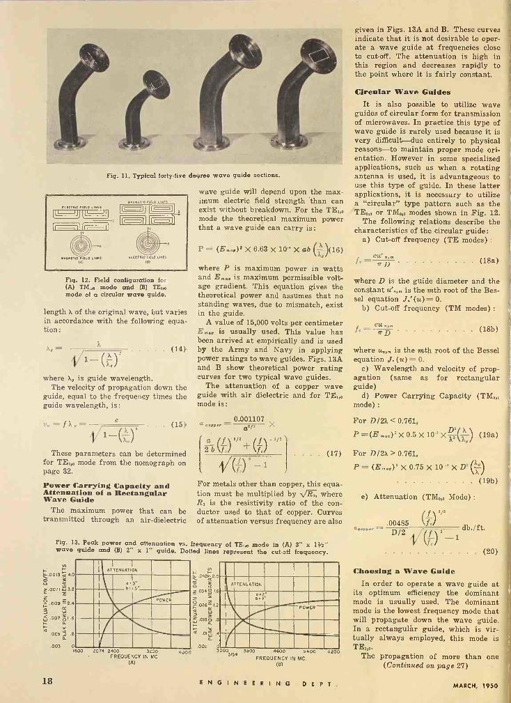
Fig. 11. Typical forty-five degree wave guide sections.
ELECTRIC HELO LINES
MAGNETIC FIELD LINES IA)
Na6NETlc FIELD LINES (o) (I )
(7-1
( L ELECTRIC FIELD LINES
I91
Fig. 12. Field configuration for (A) TM,F, mode and (B) TE,,D mode of a circular wave guide.
length X of the original wave, but varies in accordance with the following equa- tion :
x, - (14)
where X, is guide wavelength. The velocity of propagation down the
guide, equal to the frequency times the guide wavelength, is :
Iv = J -
wave guide will depend upon the max- imum electric field strength than can exist without breakdown. For the TE,,0 mode the theoretical maximum power that a wave guide can carry is:
P = (E,D,)' X 6.63 X 10-' X ab (D)(16)
where P is maximum power in watts and E,,,, is maximum permissible volt- age gradient. This equation gives the theoretical power and assumes that no standing waves, due to mismatch, exist in the guide.
A value of 15,000 volts per centimeter E... is usually used. This value has been arrived at empirically and is used by the Army and Navy in applying power ratings to wave guides. Figs. 13A and B show theoretical power rating curves for two typical wave guides.
The attenuation of a copper wave guide with air dielectric and for TE,,, mode is:
0.001107 (15) a roPeT - a'' X
These parameters can be determined for TE,,, mode from the nomograph on page 32.
Power Carrying Capacity and Attenuation of a Rectangular Wave Guide
The maximum power that can be transmitted through an air -dielectric
ab (f) ,/2 + (f)-1 /1/(1) -1
For metals otherthan copper, this equa- tion must be multiplied by VR,, where R, is the resistivity ratio of the con- ductor used to that of copper. Curves of attenuation versus frequency are also
. . (17)
Fig. 13. Peak power and attenuation vs. frequency of TE,., mode in (A) 3" x 112" wave guide and (B) 2" x 1' guide. Do ted lines represent the cut-off frequency.
1-; 1-.0013 á 4.0 m a 4 z.00!) 2 3.2
ti .009 2.4
w .007;OI.6 I_ n. F y 4
005 w .6 a
ATTENUATION
R.3"
POWER
.003 01600 2074 2400 3200
FREOUENCY IN MC
(A)
4./00
In ti F- u_ .042á2.0
3 0 4 Z.034, I.6
2 2 °.026-- I2
Ee 4 0 3 Z .0160 .8
a I- Y
01W .4 a
.002 0 3000
3154
ATTENUATION
POW ER
3000 4600 5400 FREQUENCY IN MC.
(B)
o200
given in Figs. 13A and B. These curves indicate that it is not desirable to oper- ate a wave guide at frequencies close to cut-off. The attenuation is high in this region and decreases rapidly to the point where it is fairly constant.
Circular Wave Guides It is also possible to utilize wave
guides of circular form for transmission of microwaves. In practice this type of wave guide is rarely used because it is very difficult-due entirely to physical reasons-to maintain proper mode ori- entation. However in some specialized applications, such as when a rotating antenna is used, it is advantageous to use this type of guide. In these latter applications, it is necessary to utilize a "circular" type pattern such as the TED or TM0,, modes shown in Fig. 12.
The following relations describe the characteristics of the circular guide:
a) Cut-off frequency (TE modes) :
cu' (18a)
where D is the guide diameter and the constant u'N,,, is the mth root of the Bes- sel equation JN' (u) = 0.
h) Cut-off frequency (TM modes) :
(18b)
where uN4 is the mth root of the Bessel equation JN(u)= 0.
c) Wavelength and velocity of prop- agation (same as for rectangular guide)
d) Power Carrying Capacity (TM,,, mode) :
For D/2X < 0.761,
P=(Em,r)'X0.5X10'XA() (19a)
For D/2X > 0.761,
P=(Em,.)'X0.75X10'XD'(2`--°) (19b) ï)
e) Attenuation (TM,,, Mode) :
.00485 (jT) db./ft.
(f )Z-i (20)
D/2
Choosing a Wave Guide In order to operate a wave guide at
its optimum efficiency the dominant mode is usually used. The dominant mode is the lowest frequency mode that will propagate down the wave guide. In a rectangulár guide, which is vir- tually always employed, this mode is TE,,,.
The propagation of more than one (Continued on page 27)
18 ENGINEERING D E P T. MARCH, 1950

TWO-WAY RADIO COMMUNICATION
FOR MOTORCYCLES
MADE POSSIBLE WITH .
Equipment by Tubes by
ppOrO l
AFFILIATE '
nd `
ET SYLcN1AFELECTRIC £ink Radio a v
The long arm of the Law is just that much longer through the combined skill of Link-Vetric and Sylvania. In designing this compact two-way radio for the Los Angeles Motorcycle Police, one quality was paramount ... faultless performance under the toughest conditions. Nothing must fail when the call comes through!
Link-Vetric uses Sylvania low -drain miniature tubes because every step in their manufacture is quality controlled, ensuring longer life under the most adverse conditions. From Regular Glass Tubes to the famous Lock -ins ... from Miniatures to tiny Sub - Miniatures, Sylvania tubes give the perfection that can really take punishment. Sylvania Electric Products Inc., Emporium, Pa.
I SYLV, ELE(;
NIA RIC
IADIO TUBES; CATHODE RAY TUBES, ELECTRONIC DEVICES, FLUORESCENT LAMPS. FIXTURES. SIGN TUBING, WIRING DEVICES; LIGHT BULBS; PHOTOLAMPS
Highway bumps and rutted by -ways often have to be taken at high-speed. Sylvania tubes defy sudden shock, constant vibra- tion. Maintenance work cut to a minimum.
Neatly installed either side of the rear fender, the two-way radio keeps patrol- men in constant touch with headquarters. All police calls are urgent calls ... abso- lute reliability is essential. Sylvania tubes are chosen wherever necessity demands the highest standards.
MARCH, 1950 ENGINEERING D E P T. 19
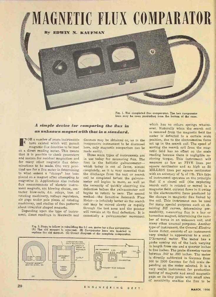
MAGNETIC FLUX COMPARATOR By EDWIN N. KAUFMAN
Fig. L The completed flux comparator. The two comparator bars may be seen protruding from the bottom of the case.
A simple device for comparing the flux in an unknown magnet with that in a standard.
FOR a number of years instruments have existed which will permit magnetic flux densities to be read
on a direct reading meter. This means that it is possible to check generators and motors for residual magnetism and for many other magnetic flux deter- minations to be made. One very prac- tical use for a flux meter is determining to what extent a "charge" has been placed on a magnet after attempting to magnetize it. Applications also include flux measurements of electric instru- ment magnets, arc blowing chutes, con- tactor blow -outs, d.c. relays, iron of rotating machinery, voltage regulators, air gaps under pole pieces of rotating machinery, and studies of flux patterns about irregular shaped magnets.
Depending upon the type of instru- ment, direct readings in Maxwells and
Gausses may be obtained or, as in the inexpensive instrument to be discussed here, only magnetic comparison can be made easily.
Three main types of instruments are in use today for measuring flux. The first is the ballistic galvanometer- which today is out of favor, almost completely, as it is very essential that the discharge from the test or search coil be completed before the galvano- meter coil begins to move, as well as the necessity of quickly observing the deflection before the galvanometer coil begins to return to zero. The second method-the Sensitive Research Flux Meter-is infinitely better as the search coil may be moved slowly or rapidly through the test area and the pointer will remain at its final deflection. It is essentially a galvanometer movement
Fig. 2. Steps to follow in rebuilding the 0-1 ma. meter for a flux comparator. (A) The old magnet is removed. (B) Comparator bars are inserted to replace the old magnet. (C) Circuit diagram of the complete comparator.
COMPARATOR BARS GOLD ROLLED STEEL
(KEEP AS 2\0 1MA MOVEMENT 5 m
Q\ 3 SHORT AS
POSSIBLE) SOOOR
NSTRUMEN T O) CASE CUTOUT w I Q
CALIBRATION
REMOVE MAGNE wESTON MODEL 301
TYPICAL TEST U. -MAGNET TOME CHECKED
MAGNET
(A) 181 (C)
which has no return springs whatso- ever. Naturally when the search coil is removed from the magnetic field the meter is deflected to a certain scale position, due to the electromotive force set up in the search coil. The speed of moving the search coil from the mag- netic field has no effect on the scale reading because there is negligible re- storing torque. This instrument will measure as low as FIVE lines per square centimeter and as high as 50 MILLION lines per square centimeter with an accuracy of of 1%. This type of instrument operates on the principle that if a closed coil (the exploring search coil) is rotated or moved in a magnetic field, current flows in it owing to the electromotive force produced by the change in magnetic flux linked by the coil. This instrument can be used for many special purposes such as ob- taining BH curves, determining per- meability, measuring flux in a bar or horseshoe magnet, determining the num- ber of turns in an unknown coil, and many other unusual purposes. Another type of instrument, the General Electric Gauss Meter, consists of an instrument very similar in appearance to a small D'Arsonval meter. The meter has a probe coming out of the back varying in length from one and a quarter inches to five inches. The probe diameter varies between .052 to .090 inches. The meter is directly calibrated in Gausses from 100 to 5000 Gausses for full scale de- pending on the meter selected. It is a very useful instrument for production testing of magnets and small magnetic gaps as its tiny probe with small area of sensitivity enables the flux to be
20 ENGINEERING D E P T. MARCH, 1950
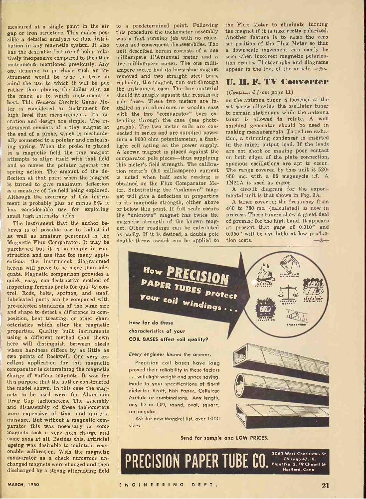
measured at a single point in the air gap or iron structure. This makes pos- sible a detailed analysis of flux distri- bution in any magnetic system. It also has the desirable feature of being rela- tively inexpensive compared to the other instruments mentioned previously. Any one desiring to purchase such an in- strument would be wise to bear in mind the use to which it will be put rather than placing the dollar sign as the mark as to which instrument is best. This General Electric Gauss Me- ter is considered an instrument for high level flux measurements. Its op- eration and design are simple. The in- strument consists of a tiny magnet at the end of a probe, which is mechanic- ally connected to a pointer and restrain- ing spring. When the probe is placed in a magnetic field the tiny magnet attempts to align itself with that field and so moves the pointer against the spring action. The amount of the de- flection at that point when the magnet is turned to give maximum deflection is a measure of the field being explored. Although the accuracy of this instru- ment is probably plus or minus 5% it has considerable use for exploring small high intensity fields.
The instrument that the author be- lieves is of possible use to industrial as well as amateur personnel is the Magnetic Flux Comparator. It may be purchased but it is so simple in con- struction and use that for many appli- cations the instrument diagrammed herein will prove to be more than ade- quate. Magnetic comparison provides a quick, easy, non-destructive method of inspecting ferrous parts for quality con- trol. Rods, bolts, springs, and small fabricated parts can be compared with pre -selected standards of the same size and shape to detect a difference in com- position, heat treating, or other char- acteristics which alter the magnetic
I properties. Quality built instruments using a different method than shown here will distinguish between steels whose hardness differs by as little as two points of Rockwell. One very ex- cellent application for this magnetic comparator is determining the magnetic charge of various magnets. It was for this purpose that the author constructed the model shown. In this case the mag- nets to be used were for Aluminum Drag Cup tachometers. The assembly and disassembly of these tachometers were expensive of time and quite a nuisance. But without a magnetic com- parator this was necessary as some magnets took a very high charge and some none at all. Besides this, artificial ageing was desirable to maintain reas- onable calibration. With the magnetic comparator as a check numerous un- charged magnets were charged and then discharged by a strong alternating field
to a predetermined point. Following this procedure the tachometer assembly was a fast running job with no rejec- tions and consequent disassemblies. The unit described herein consists of a one milliampere D'Arsonval meter and a five milliampere meter. The one milli- ampere meter had its horseshoe magnet removed and two straight steel bars, replacing the magnet, run out through the instrument case. The bar material should fit snugly against the remaining pole faces. These two meters are in- stalled in an aluminum or wooden case with the two "comparator" bars ex- tending through the case (see photo- graph). The two meter coils are con- nected in series and are supplied power thru a 5000 ohm potentiometer, a flash- light cell acting as the power supply. A known magnet is placed against the comparator pole pieces-thus supplying this meter's field strength. The calibra- tion meter's (5.0 milliampere) current is noted when half scale reading is obtained on the Flux Comparator Me- ter. Substituting the "unknown" mag- net will give a deflection in proportion to its magnetic strength, either above or below this point. If full scale occurs the "unknown" magnet has twice the magnetic strength of the known mag- net. Other readings can be calculated as easily. If it is desired, a double pole double throw switch can be applied to
the Flux Meter to eliminate turning the magnet if it is incorrectly polarized. Another feature is to raise the zero set position of the Flux Meter so that a downscale movement can easily be seen when incorrect magnetic polariza- tion occurs. Photographs and diagrams appear in the text of the article. -.0--
U. H. F. TV Converter (Continued from page 11)
on the antenna tuner is loosened at the set screw allowing the oscillator tuner to remain stationary while the antenna tuner is allowed to rotate. A well shielded generator should be used in making measurements. To reduce radia- tion, a trimming condenser is inserted in the mixer output lead. If the leads are not short or making poor contact on both edges of the plate connection, spurious oscillations are apt to occur. The range covered by this unit is 520- 950 mc. with a 55 megacycle i.f. A 1N21A is used as mixer.
A circuit diagram for the experi- mental unit is that shown in Fig. 3A.
A tuner covering the frequency from 460 to 750 mc. (calculated) is now in process. These tuners show a great deal of promise for the high band. It appears at present that gaps of 0.010" and 0.050" will be available at low produc- tion costs. +®+
How far do these
characteristics of your COIL BASES affect coil quality?
Every engineer knows the answer.
Precision coil bases have long proved their reliability in these factors ... with light weight and space saving. Made to your specifications of finest dielectric Kraft, Fish Paper, Cellulose Acetate or combinations. Any length, any ID or OD, round, oval, square, rectangular.
Ask for new Mandrel list, over 1000 sizes.
Send for sample and LOW PRICES.
PRECISION PAPER TUBE 2063
Chicago West Ch4ar7,
111.
leston St.
Plant No. 2, 79 7, III. S. Hartford, Conn.
MARCH, 1950 ENGINEERING D E P T. 21

at the ör, gas-
- cent early ,,per
the
Fa wór... serves were a levi rise of $100,000,00
r at" of $
ted f; 1 r of prey k $9 x0',000, and a cue
aie of $2,265,000 in system dings of '' " government ,A
'o
TV USED IN MEDICAL EDUCATION
A new method of applying television to medical teaching developed by Wil- liam L. Norvell, manager of Remington Rand's television department, was re-
cently demonstrated during the Third Annual Clinical Session of the Amer- ican Medical Association in Washing- ton, D. C.
With Vericon, a system of closed-cir- cuit television, the visual images of var- ious internal organs of the body can now be televised for group study without resorting to surgery. The system in- corporates a special optical link de- vised by Mr. Norvell and interposed between the eyepiece of a standard gastroscope and the pickup tube of the television camera.
IRE SPRING CONFERENCE
Saturday, April 29th is the date set for the Cincinnati Section of the Insti- tute of Radio Engineers Fourth Annual Spring Technical Conference at the Engineering Society Headquarters in Cincinnati.
The theme of the conference will be "Television" and sessions will be held morning and afternoon and exhibits will be on display. The day's proceed' ings will be climaxed by a banquet fea- turing a prominent speaker.
TELREX APPOINTS ENGINEERS
Telrex, Inc., of Asbury Park, New Jersey, has announced three recent ap- pointments to its Engineering Staff. Those appointed are: Dr. H. Giuliani as Chief Chemical and Mechanical En- gineer, Mr. Irvin Guttman as Chief Electronics Project Engineer and Sales Engineer, and Mr. Joseph P. Stephanile as Associate Electronics Engineer.
Dr. Giuliani formerly conducted re- search and development work at the Sheffield Engineering School, Yale Uni -
sta - , es in cash money
rtaih officers high f>$ r ran 0c$ 0 ivally.
uneratfo álss princ uclb disco nuing th plan heretofore in effect provid
' for the purchase of sigle pr annuiti
versity, and will direct many phases of plant development at Telrex.
Mr. Guttman was formerly asso- ciated with several prominent Elec- tronics engineering firms as well as the U. S. Signal Corps Laboratories in Eatontown and Belmar in various en- gineering capacities.
Previously engaged in technical and engineering work with several Govern- ment installations, Mr. Stephanile joined Telrex in June and is conducting expe- rimental work on new equipment.
DR. ULREY RETIRES
Dr. Dayton Ulrey, an early researcher into vacuum tube design and well-known as an administrator and teacher, has
retired as Chief Engineer of the Lan- caster, Pa., plant of the RCA Tube Department.
Dr. Ulrey's contributions to radio and television research include the de- velopment of processes for creating vacuum -tight metal -to -glass seals, the vital principle used in today's metal - coned television picture tubes. He was also responsible for important studies in the production of high vacuum, par- ticularly the absorption and evolution of gases by glass and metals. Dr. Ulrey is shown examining one of the many intricate electron tubes which is the result of his development work.
RCA has announced that Dr. Ulrey will be retained as consultant to the company.
REVISE WWV SERVICES
A new series of technical radio broad- cast services over radio stations WWV, Beltsville, Md., and WWVH, Maui, Ter-
ritory of Hawaii, has been inaugurated by the National Bureau of Standards.
Revised services will not differ greatly from those given in the past, and include: (1) standard radio fre- quencies of 2.5, 5, 10, 15, 20, 25, 30, and 35 megacycles, (2) time announce- ments at 5 -minute intervals by voice and International Morse code, (3) standard time intervals of 1 second, 4, and 5 minutes, (4) standard audio frequencies of 440 cycles and 600 cycles, (5) radio propagation disturbance warnings by International Morse code consisting of the letters W, U, or N, indicating warning, unstable conditions, or normal, respectively.
Radio station WWVH, recently estab- lished in Hawaii, broadcasts on an experimental basis on 5, 10, and 15 megacycles. The program of broadcasts on the three frequencies is essentially the same as that of station WWV.
Reports on reception are welcomed, and further information on these serv- ices, as well as forms on which to submit such reports, may be obtained on request from the National Bureau of Standards, Washington 25, D. C.
10th ANNIVERSARY FOR WRGB
General Electric's television station WRGB at Schenectady, N. Y., recently celebrated its 10th. anniversary which marked the beginning of a new, com- pletely modernized station containing the latest General Electric equipment throughout.
The studio has been enlarged to make room for a new master control room which acts as a control center for the entire system and is the distribution point for programs from the local stu- dio, network programs which are brought from New York via the GE microwave relay and from the WRGB mobile pickup equipment.
At WRGB's master control panel, Stanley Godell is shown controlling the
quality of the photo being transmitted. This control panel is part of the sta- tion's new equipment, including cam- eras, control and transmitting equip- ment made at the General Electric Company's Electronics Park plant in
22 ENGINEERING D E P T. MARCH, 1950
Syracuse, N. Y. Installation of the new facilities was completed on the eve of WRGB's 10th anniversary.
TV TUBE PRODUCTION INCREASES
Sylvania Electric Products Inc., New Yolk, is expecting to set a new record in television tube production ìn 1950. With six television picture tubes per minute now coming off conveyorized production lines, production is now run- ning 33fe times last year's rate.
Photograph shows a cleaning and in- side -coating station under a conveyor
in the Ottawa, Ohio, picture -tube plant where both metal and glass tubes are processed side -by -side.
Sylvania's second new plant in Sen- eca Falls, N. Y., is reported to be near completion and both plants will produce standard and "gray -face" tubes and the new "short" and rectangular -face types.
I.R.E. AWARDS
Announcement has been made of the I.R.E. awards which will be presented at the annual I.R.E. Convention in New York. The awards and recipients are as follows:
Browder J. Thompson Memorial Prize, Joseph F. Hull and Arthur W. Randals.
Editor's Award, E. J. Barlow. Morris Liebmann Memorial Prize,
Otto H. Schade. Harry Diamond Memorial Award,
Andrew V. Haeff. Medal of Honor, Frederick E. Ter -
man. In addition to the above, thirty Fellow
awards will be presented.
REFLECTION OF RADIO WAVES
A system whereby radio waves are being reflected around a mountain in Pennsylvania has been reported by A. A. Johnson, manager of central station engineering for the Westinghouse Elec- tric Corporation.
A microwave communication system recently installed between a sub -station and generating plant of the Pennsyl-
vania Electric Company at Johnstown has shown the reflection principle to be both efficient and economical.
Since the sub -station and generating plant were 12 miles apart with a large hill between, microwaves were reflected around it. In operation the microwaves are beamed at a large aluminum re- flector sheet placed some two miles from the sub -station. This sheet, which meas- ures 20 ft. square, is mounted on a 50 -foot tower and is in the "line of sight" of both the sub -station and the generating plant. Microwaves striking this mirror-like reflector are deflected around the side of the mountain to the receiving apparatus.
ELECTRON DIFFRACTION INSTRUMENT
An electron diffraction instrument which can "see" film surfaces as thin as two millionths of an inch is being used in the development of new and improved lubricants and catalysts at the California Research Corporation (subsidiary of Standard Oil Company of California) at Richmond, California.
The instrument, developed by General Electric, is said to be the most sensitive device yet developed for observing chem- ical and physical changes in extremely thin films. Before development of this equipment, the only means of studying these very thin films was by x-ray dif-
fraction or chemical analysis, which show only one chemical composition. Electron diffraction photographs will reveal a very thin surface layer of an- other material.
Shown is the GE electron diffraction instrument in use. According to Cali- fornia Research engineers, the electron diffraction method permits a truer eval- uation of surface-active materials, and may lead to the discovery of new lubri- cants or lubricant additives. Another important advantage of this method is the speed with which the analysis of surfaces and thin films can be made.
SAFEGUARD FOR ATOMIC LABS
An instrument which measures simul- taneously the extent of beta and gamma contamination on hands and feet of those engaged in handling radioactive material, while compensating automat -
(Continued on page 29)
Over 1000 Sizes
PARAMOUNT SPIRAL WOUND PAPER TUBES
Square Rectangular Triangular Round and Half -Round
With a wide range of stock arbors ... plus the specialized ability to engineer special tubes .. .
PARAMOUNT can produce the exact shape and size you need for coil forms or other uses. Hi -Dielectric, Hi -Strength. Kraft, Fish Paper, Red Rope, or any combination, wound on automatic machines. Tol- erances plus or minus .002'. Made to your speci- fications or engineered for YOU.
Inside Perimeters from .592' to 19.0'
PARAMOUNT PAPER TUBE CORP. 613 LAFAYETTE ST., FORT WAYNE 2, IND.
Manufacturers of Paper Tubing for the Electrical Industry
MARCH, 1950 ENGINEERING DEPT. 23
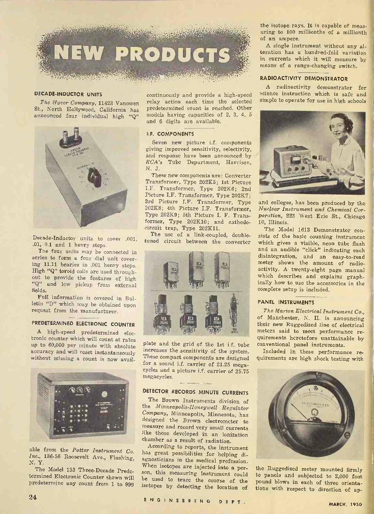
DECADE -INDUCTOR UNITS
The Hycor Company, 11423 Vanowen St., North Hollywood, California has announced four individual high "Q"
Decade -Inductor units to cover .001, .01, 0.1 and 1 henry steps.
The four units may be connected in series to form a four dial unit cover- ing 11.11 henries in .001 henry steps. High "Q" toroid coils are used through- out to provide the features of high "Q" and low pickup from external fields.
Full information is covered in Bul- letin "D" which may be obtained upon request from the manufacturer.
PREDETERMINED ELECTRONIC COUNTER
A high-speed predetermined elec- tronic counter which will count at rates up to 60,000 per minute with absolute accuracy and will reset instantaneously without missing a count is now avail-
able from the Potter Instrument Co. Inc., 136-56 Roosevelt Ave., Flushing, N. Y.
The Model 133 Three -Decade Prede- termined Electronic Counter shown will predetermine any count from 1 to 999
continuously and provide a high-speed relay action each time the selected predetermined count is reached. Other models having capacities of 2, 3, 4, 5
and 6 digits are available.
I.F. COMPONENTS
Seven new picture i.f. components giving improved sensitivity, selectivity, and response have been announced by RCA's Tube Department, Harrison, N. J.
These new components are: Converter Transformer, Type 202K5; 1st Picture I.F. Transformer, Type 202K6; 2nd Picture I.F. Transformer, Type 202K7; 3rd Picture I.F. Transformer, Type 202K8; 4th Picture I.F. Transformer, Type 202K9; 5th Picture I. F. Trans- former, Type 202K10; and cathode - circuit trap, Type 202K11.
The use of a link -coupled, double - tuned circuit between the converter
7en
plate and the grid of the 1st i.f. tube increases the sensitivity of the system. These compact components are designed for a sound i.f. carrier of 21.25 mega- cycles and a picture i.f. carrier of 25.75 megacycles.
DETECTOR RECORDS MINUTE CURRENTS
The Brown Instruments division of the Minneapolis -Honeywell Regulator Company, Minneapolis, Minnesota, has designed the Brown electrometer to measure and record very small currents like those developed in an ionization chamber as a result of radiation.
According to reports, the instrument has great possibilities for helping di- agnosticians in the medical profession. When isotopes are injected into a per- son, this measuring instrument could be used to trace the course of the isotopes by detecting the location of
the isotope rays. It is capable of meas- uring to 100 millionths of a millionth of an ampere.
A single instrument without any al- teration has a hundred -fold variation in currents which it will measure by means of a range -changing switch.
RADIOACTIVITY DEMONSTRATOR
A radioactivity demonstrator for science instruction which is safe and simple to operate for use in high schools
and colleges, has been produced by the Nuclear Instrument and Chemical Cor- poration, 223 West Erie St., Chicago 10, Illinois.
The Model 1613 Demonstrator con- sists of the basic counting instrument which gives a visible, neon tube flash and an audible "click" indicating each disintegration, and an easy -to -read meter shows the amount of radio- activity. A twenty-eight page manual which describes and explains graph- ically how to use the accessories in the complete setup is included.
PANEL INSTRUMENTS
The Marion Electrical Instrument Co., of Manchester, N. H. is announcing their new Ruggedized line of electrical meters said to meet performance re- quirements heretofore unattainable by conventional panel instruments.
Included in these performance re- quirements are high shock testing with
the Ruggedized meter mounted firmly to panels and subjected to 2,000 foot pound blows in each of three orienta- tions with respect to direction of ap-
24 ENGINEERING D E P T, MARCH, 1950
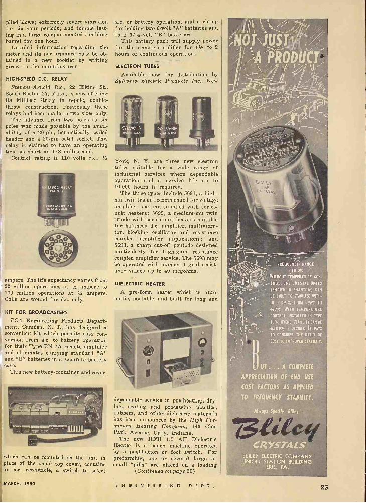
plied blows; extremely severe vibration for six hour periods; and tumble test- ing in a large compartmented tumbling barrel for one hour.
Detailed information regarding the meter and its performance may be ob- tained in a new booklet by writing direct to the manufacturer.
HIGH-SPEED D.C. RELAY
Stevens -Arnold Inc., 22 Elkins St., South Boston 27, Mass., is now offering its Millisec Relay in 6 -pole, double - throw construction. Previously these relays had been' made in two sizes only.
The advance from two poles to six poles was made possible by the avail- ability of a 20 -pin, hermetically sealed header and a 20 -pin octal socket. This relay is claimed to have an operating time as short as 1/3 millisecond.
Contact rating is 110 volts d.c., 3/2
MOeLiSEC RELAY
5fY[.5 eFM0O 'NL, M10510,
[i
ampere. The life expectancy varies from 22 million operations at 3/2 ampere to 100 million operations at 3/4 ampere. Coils are wound for d.c. only.
KIT FOR BROADCASTERS
RCA Engineering Products Depart- ment, Camden, N. J., has designed a convenient kit which permits easy con- version from a.c. to battery operation for their Type BN -2A remote amplifier and eliminates carrÿing standard "A" and "B" batteries in a separate battery case.
This new battery -container and cover,
which can be mounted on place of the usual top cover, contains an a.c. receptacle, a switch to select
the unit in
a.c. or battery operation, and a clamp for holding two 6 -volt "A" batteries and four 673 -volt "B" batteries.
This battery pack will supply power for the remote amplifier for 11/2 to 2
hours of continuous operation.
ELECTRON TUBES
Available now for distribution by Sylvania Electric Products Inc., New
York, N. Y. are three new electron tubes suitable for a wide range of industrial services where dependable operation and a service life up to 10,000 hours is required.
The three types include 5691, a high - mu twin triode recommended for voltage amplifier use and supplied with series - unit heaters; 5692, a medium -mu twin triode with series -unit heaters suitable for balanced d.c. amplifier, multivibra- tor, blocking oscillator and resistance coupled amplifier applications; and 5693, a sharp cut-off pentode designed particularly for high -gain resistance coupled amplifier service. The 5693 may be operated with number 1 grid resist- ance values up to 40 megohms.
DIELECTRIC HEATER
A pre -form heater which is auto- matic, portable, and built for long and
dependable service in pre -heating, dry- ing, sealing and processing plastics, rubbers, and other dielectric materials has been announced by the High Fre- quency Heating Company, 143 Glen Park Avenue, Gary, Indiana.
The new HFH 1.5 AH Dielectric Heater is a bench machine operated by a pushbutton or foot switch. For preforming, one or several large or small "pills" are placed on a loading
(Continued on page 30)
FREQUENCY. RANGE
1100 MC
WITHOUT TEMPERATURE CON-
TROI, BH6 CRYSTAL UNITS
(SHOWN IN PHANTOM) CAN
BE BUILT TO STABILIZE WITH-
IN ±.0015% FROM -55'C TO
+90'C. WITH TEMPERATURE
CONTROL, INSTALLED IN TYPE
1 ¡COT OVENS, STABILITY CAN BE
±.0001% IF DESIRED. 1T PAYS
TO CONSIDER THE RATIO OF
-B COST TO IMPROVED STABILITY.
J UT ... A COMPLETE
APPRECIATION OF END USE
COST FACTORS AS APPLIED
TO FREQUENCY STABILITY.
ACS.. BLILEY ELECTRIC COMPANY UNION STATION BUILDING
ERIE, PA.
MARCH, 1950 ENGINEERING D E P T. 25
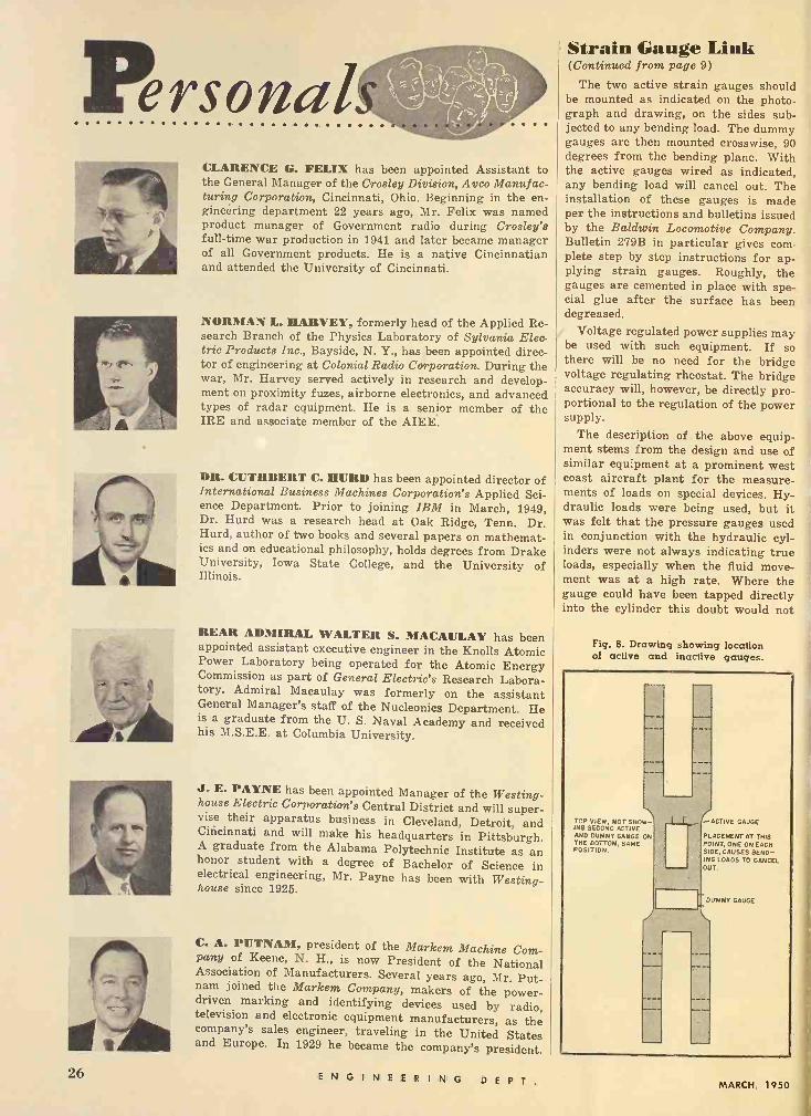
CLARENCE G. FELIX has been appointed Assistant to the General Manager of the Crosley Division, Avco Manufac- turing Corporation, Cincinnati, Ohio. Beginning in the en- gineering department 22 years ago, Mr. Felix was named product manager of Government radio during Crosley's full-time war production in 1941 and later became manager of all Government products. He is a native Cincinnatian and attended the University of Cincinnati.
NORMAN L. HARVEY, formerly head of the Applied Re- search Branch of the Physics Laboratory of Sylvania Elec- tric Products Inc., Bayside, N. Y., has been appointed direc- tor of engineering at Colonial Radio Corporation. During the war, Mr. Harvey served actively in research and develop- ment on proximity fuzes, airborne electronics, and advanced types of radar equipment. He is a senior member of the IRE and associate member of the AIEE.
DR. CUTHBERT C. HURD has been appointed director of International Business Machines Corporation's Applied Sci- ence Department. Prior to joining IBM in March, 1949, Dr. Hurd was a research head at Oak Ridge, Tenn. Dr. Hurd, author of two books and several papers on mathemat- ics and on educational philosophy, holds degrees from Drake University, Iowa State College, and the University of Illinois.
REAR ADMIRAL WALTER S. MACAULAY has been appointed assistant executive engineer in the Knolls Atomic Power Laboratory being operated for the Atomic Energy Commission as part of General Electric's Research Labora- tory. Admiral Macaulay was formerly on the assistant General Manager's staff of the Nucleonics Department. He is a graduate from the U. S. Naval Academy and received his M.S.E.E. at Columbia University.
J. E. PAYNE has been appointed Manager of the Westing- house Electric Corporation's Central District and will super- vise their apparatus business in Cleveland, Detroit, and Cincinnati and will make his headquarters in Pittsburgh. A graduate from the Alabama Polytechnic Institute as an honor student with a degree of Bachelor of Science in electrical engineering, Mr. Payne has been with Westing- house since 1925.
C. A. PUTNAM, president of the Markem Machine Com- pany of Keene, N. H., is now President of the National Association of Manufacturers. Several years ago, Mr. Put- nam joined the Markem Company, makers of the power - driven marking and identifying devices used by radio, television and electronic equipment manufacturers, as the company's sales engineer, traveling in the United States and Europe. In 1929 he became the company's president.
Strain Gauge Link (Continued from page 9)
The two active strain gauges should be mounted as indicated on the photo- graph and drawing, on the sides sub- jected to any bending load. The dummy gauges are then mounted crosswise, 90 degrees from the bending plane. With the active gauges wired as indicated, any bending load will cancel out. The installation of these gauges is made per the instructions and bulletins issued by the Baldwin Locomotive Company. Bulletin 279B in particular gives com- plete step by step instructions for ap- plying strain gauges. Roughly, the gauges are cemented in place with spe- cial glue after the surface has been degreased.
Voltage regulated power supplies may be used with such equipment. If so there will be no need for the bridge voltage regulating rheostat. The bridge accuracy will, however, be directly pro- portional to the regulation of the power supply.
The description of the above equip- ment stems from the design and use of similar equipment at a prominent west coast aircraft plant for the measure- ments of loads on special devices. Hy- draulic loads were being used, but it was felt that the pressure gauges used in conjunction with the hydraulic cyl- inders were not always indicating true loads, especially when the fluid move- ment was at a high rate. Where the gauge could have been tapped directly into the cylinder this doubt would not
Fig. 6. Drawing showing location of active and inactive gauges.
TOP VIEW, NOT SHOW- ING SECOND ACTIVE AND DUMMY GAUGE ON THE BOTTOM, SANE POSITION.
I I ACTIVE GAUGE
PLACEMENT AT THIS POINT, ONE ON EACH SIDE, CAUSES BEND- ING LOADS TO CANCEL Our.
DUMMY GAUGE
96 ENGINEERING D E P T, MARCH, 1950
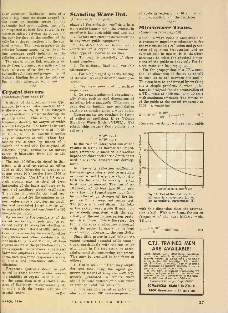
have occurred. Calibration tests of a special jig, using the strain gauge link, did show up serious errors in the hydraulic load computations, but only as suspected at high flow rates. A re- striction existed between the gauge and the cylinder through the smallest of the cylinder outlet connections and the con- necting hose. This back pressure on the cylinder became much higher than the line pressure could indicate, as the cylinder piston was forced down rapidly.
The strain gauge link operating di- rectly from the mover can indicate true load, whereas other devices such as hydraulic cylinders and gauges may not indicate binding loads in the cylinder, jig, or other associated equipment.
Crystal Savers . (Continued from page 13)
A circuit of the direct synthesis type, adapted to the 75 meter amateur band, is illustrated in Fig. 3. A 100 kilocycle crystal oscillator is used to develop the primary signal. This is applied to a frequency divider, the output of which is at 10 kilocycles. The latter is in turn multiplied so that harmonics at 10, 20, 30, 40, 50, 60, 70, 80, and 90 kilocycles may be obtained at will. These har- monics are selected by means of a switch and mixed with the original 100 kilocycle signal, producing an output every 10 kilocycles from 100 to 190 kilocycles.
The 100-190 -kilocycle signal is then mixed with another signal at either 3700 or 3800 kilocycles to produce an output every 10 kilocycles from 3800 to 3990 kilocycles. The 3.7 and 3.8 mega- cycle signals may be obtained from harmonics of the basic oscillator or by means of auxiliary crystal oscillators. The latter is probably the most eco- nomical method for the amateur or ex- perimenter since a distorter, an ampli- fier and associated tuned circuits will be required to derive them from the 100 kilocycle oscillator.
By increasing the complexity of the circuit somewhat, outputs may be ob- tained every 10 kilocycles starting at 3805 kilocycles instead of 3800. Adapta- tions can also readily be made for other frequencies and other amateur bands. The main thing to watch in any of these crystal savers is the production of spu- rious signals. Since several mixers and harmonic amplifiers are used in any of them, such unwanted responses are easy to obtain and sometimes difficult to eliminate.
Frequency synthesis should be wel- comed by those amateurs who demand the stability of crystal oscillators but at the same time wish a certain de- gree of flexibility not economically at- tainable with the usual methods of crystal control. 0.,..
Standing Wave Bet. (Continued from page 6)
phase of the reflection coefficient in a wave guide transmission line system, in practice it has such additional uses as:
1. To measure effect of discontinuities in any wave guide equipment.
2. To determine rectification char- acteristics of a crystal, bolometer or other type of detector or rectifier.
3. To measure directivity of direc- tional couplers.
4. To calibrate fixed and variable attenuators.
5. For simple rapid quantity testing of standard wave guide component pro- duction.
6. For measurement of normalized impedances.
7. To predetermine and experiment- ally check position and dimensions of matching irises and stubs. This may be expanded to include any constriction existing or developing in a wave guide.
Measurements are obtained in terms of reflection coefficient K or Voltage Standing Wave Ratio (VSWR). The relationship between these values is as follows:
VSWR -1 K - VSWR 1 In the case of interpretations of the
results in terms of normalized imped- ance, reference is made to a standard impedance chart such as the Smith chart used in advanced research and develop- ment.
In measuring reflection coefficients, the signal generator should be as stable as possible and the probe should dis- turb the fields in the wave guide the least possible amount. The use of an attenuator of not less than 20 db. pre- vents the tube (signal generator) from being affected by changes of the -im- pedance for a component under test. The probe will least disturb the fields in the slotted wave guide if minimum probe depth consistent with the sen- sitivity of the output measuring equip- ment is employed. This is the reason for tuning the coaxial structure connected with the probe. It can thus be kept small without decreasing the sensitivity.
Since little power is available at the output terminal (coaxial cable connec- tion), particularly with the use of an attenuator in the test setup, it neces- sitates sensitive measuring equipment. This may be provided in the form of either:
1. Use of an audio frequency ampli- fier and modulating the signal gen- erator by means of a square wave sep- arately generated. A square wave should be used instead of a sine wave in order to avoid FM behavior.
2. The use of a sensitive galvanom- eter (not over .001 microampere/mm
of scale deflection on a 10 cm. scale) and c.w. conditions in the oscillator.
Microwave Trans. (Continued from page 18)
mode in a wave guide is undesirable as it results in impedance mismatches for the various modes; reflection and gener- ation of spurious frequencies; and an over-all loss in power. It is therefore necessary to select the physical dimen- sions of the guide so that only the de- sired mode can be propagated.
For the propagation of a TE1,o mode the "a" dimension of the guide should be such as to fall between a/2 and X.
This can best be understood by working out a simple problem. A wave guide must be designed for the propagation of a TE:,o mode at 3000 me. (X = 10 cm.) with maximum efficiency. The dimension of the guide at the cut-off frequency of 3000 mc. would be:
3 10° =3 2x0" ; x=5 cm. . . (21)
However, we do not want to use a guide
25 303
e i 1..
.Ixq >
s
054 >
º
$
i i 00
2 3 NORMALIZED SUSCEPTANCE
Fig. 14. Plot of the distance from minimum to susceptance (d:) vs. the normalized susceptance (B).
with this dimension since the attenua- tion is high. With a = 5 cm., the cut-off frequency of the next highest mode, TE:,o is:
3 X'° 0 _ 6000 mc (22)
C.T.I. TRAINED MEN ARE AVAILABLE!
Each month C.T.I. graduates ambitious young men who have completed an in- tensive course in Radio and Television maintenance and repairing. Their train- ing has been practical. They've learned by working on modern equipment under personal, expert supervision.
It you need a trained technician, we invite you to write for an outline of our course, and for a prospectus of the grad- uate. (No fees, of course). Address:
Placement Manager, Dept. P1064
COMMERCIAL TRADES INSTITUTE
1400 Greenleaf Chicago 26
MARCH, 1950 ENGINEERING D E P T. 27

CLARENCE G. FELIX has been appointed Assistant to the General Manager of the Crosley Division, Avco Manufac- turing Corporation, Cincinnati, Ohio. Beginning in the en- gineering department 22 years ago, Mr. Felix was named product manager of Government radio during Crosley's full-time war production in 1941 and later became manager of all Government products. He is a native Cincinnatian and attended the University of Cincinnati.
NORMAN L. HARVEY, formerly head of the Applied Re- search Branch of the Physics Laboratory of Sylvania Elec- tric Products Inc., Bayside, N. Y., has been appointed direc- tor of engineering at Colonial Radio Corporation. During the war, Mr. Harvey served actively in research and develop- ment on proximity fuzes, airborne electronics, and advanced types of radar equipment. He is a senior member of the IRE and associate member of the AIEE.
DR. CUTHBERT C. HURD has been appointed director of International Business Machines Corporation's Applied Sci- ence Department. Prior to joining IBM in March, 1949, Dr. Hurd was a research head at Oak Ridge, Tenn. Dr. Hurd, author of two books and several papers on mathemat- ics and on educational philosophy, holds degrees from Drake University, Iowa State College, and the University of Illinois.
REAR ADMIRAL WALTER S. MACAULAY has been appointed assistant executive engineer in the Knolls Atomic Power Laboratory being operated for the Atomic Energy Commission as part of General Electric's Research Labora- tory. Admiral Macaulay was formerly on the assistant General Manager's staff of the Nucleonics Department. He is a graduate from the U. S. Naval Academy and received his M.S.E.E. at Columbia University.
J. E. PAYNE has been appointed Manager of the Westing- house Electric Corporation's Central District and will super- vise their apparatus business in Cleveland, Detroit, and Cincinnati and will make his headquarters in Pittsburgh. A graduate from the Alabama Polytechnic Institute as an honor student with a degree of Bachelor of Science in electrical engineering, Mr. Payne has been with Westing- house since 1925.
C. A. PUTNAM, president of the Markem Machine Com- pany of Keene, N. H., is now President of the National Association of Manufacturers. Several years ago, Mr. Put- nam joined the Markem Company, makers of the power - driven marking and identifying devices used by radio, television and electronic equipment manufacturers, as the company's sales engineer, traveling in the United States and Europe. In 1929 he became the company's president.
Strain Gauge Link (Continued from page 9)
The two active strain gauges should be mounted as indicated on the photo- graph and drawing, on the sides sub- jected to any bending load. The dummy gauges are then mounted crosswise, 90 degrees from the bending plane. With the active gauges wired as indicated, any bending load will cancel out. The installation of these gauges is made per the instructions and bulletins issued by the Baldwin Locomotive Company. Bulletin 279B in particular gives com- plete step by step instructions for ap- plying strain gauges. Roughly, the gauges are cemented in place with spe- cial glue after the surface has been degreased.
Voltage regulated power supplies may be used with such equipment. If so there will be no need for the bridge voltage regulating rheostat. The bridge accuracy will, however, be directly pro- portional to the regulation of the power supply.
The description of the above equip- ment stems from the design and use of similar equipment at a prominent west coast aircraft plant for the measure- ments of loads on special devices. Hy- draulic loads were being used, but it was felt that the pressure gauges used in conjunction with the hydraulic cyl- inders were not always indicating true loads, especially when the fluid move- ment was at a high rate. Where the gauge could have been tapped directly into the cylinder this doubt would not
Fig. 6. Drawing showing location of active and inactive gauges.
TOP VIEW, NOT SHOW- ING SECOND ACTIVE AND DUMMY GAUGE ON THE BOTTOM, SAME POSITION.
L -ACTIVE GAUGE
PLACEMENT AT THIS POINT, ONE ON EACH SIDE, CAUSES BEND- ING LOADS TO CANCEL OUT.
DUMMY GAUGE
26 ENGINEERING D E P T. MARCH, 1950
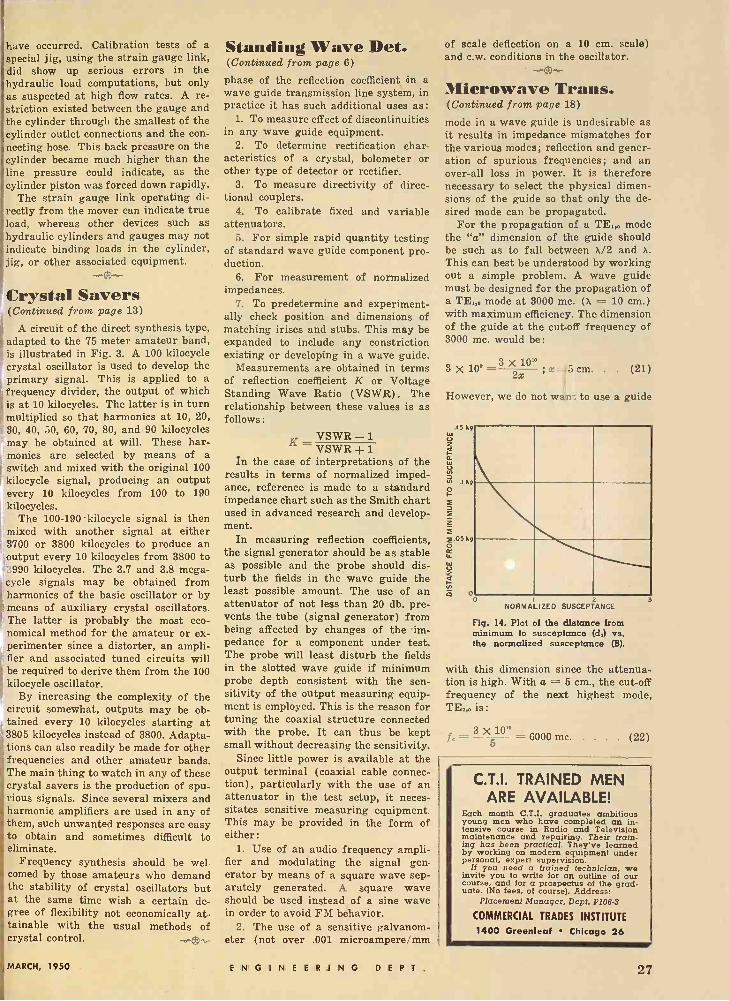
have occurred. Calibration tests of a special jig, using the strain gauge link, did show up serious errors in the hydraulic load computations, but only as suspected at high flow rates. A re- striction existed between the gauge and the cylinder through the smallest of the cylinder outlet connections and the con- necting hose. This back pressure on the cylinder became much higher than the line pressure could indicate, as the cylinder piston was forced down rapidly.
The strain gauge link operating di- rectly from the mover can indicate true load, whereas other devices such as hydraulic cylinders and gauges may not indicate binding loads in the cylinder, jig, or other associated equipment.
b-g- Crystal Savers (Continued from page 13)
A circuit of the direct synthesis type, adapted to the 75 meter amateur band, is illustrated in Fig. 3. A 100 kilocycle crystal oscillator is used to develop the primary signal. This is applied to a frequency divider, the output of which is at 10 kilocycles. The latter is in turn multiplied so that harmonics at 10, 20, 30, 40, 50, 60, 70, 80, and 90 kilocycles may be obtained at will. These har- monics are selected by means of a
rswitch and mixed with the original 100 kilocycle signal, producing an output every 10 kilocycles from 100 to 190 kilocycles.
The 100-190 kilocycle signal is then mixed with another signal at either 3700 or 3800 kilocycles to produce an output every 10 kilocycles from 3800 to 3990 kilocycles. The 3.7 and 3.8 mega- cycle signals may be obtained from harmonics of the basic oscillator or by means of auxiliary crystal oscillators. The latter is probably the most eco- nomical method for the amateur or ex- perimenter since a distorter, an ampli- fier and associated tuned circuits will be required to derive them from the 100 kilocycle oscillator.
By increasing the complexity of the circuit somewhat, outputs may be ob- tained every 10 kilocycles starting at 3805 kilocycles instead of 3800. Adapta- tions can also readily be made for other frequencies and other amateur bands. The main thing to watch in any of these crystal savers is the production of spu- rious signals. Since several mixers and harmonic amplifiers are used in any of them, such unwanted responses are easy to obtain and sometimes difficult to eliminate.
Frequency synthesis should be wel- comed by those amateurs who demand the stability of crystal oscillators but at the same time wish a certain de- gree of flexibility not economically at- tainable with the usual methods of crystal control. .,
Standing Wave Det. (Continued from page 6)
phase of the reflection coefficient in a wave guide transmission line system, in practice it has such additional uses as:
1. To measure effect of discontinuities in any wave guide equipment.
2. To determine rectification char- acteristics of a crystal, bolometer or other type of detector or rectifier.
3. To measure directivity of direc- tional couplers.
4. To calibrate fixed and variable attenuators.
5. For simple rapid quantity testing of standard wave guide component pro- duction.
6. For measurement of normalized impedances.
7. To predetermine and experiment- ally check position and dimensions of matching irises and stubs. This may be expanded to include any constriction existing or developing in a wave guide.
Measurements are obtained in terms of reflection coefficient K or Voltage Standing Wave Ratio (VSWR). The relationship between these values is as follows :
VSWR -1 K VSWR -}- 1
In the case of interpretations of the results in terms of normalized imped- ance, reference is made to a standard impedance chart such as the Smith chart used in advanced research and develop- ment.
In measuring reflection coefficients, the signal generator should be as stable as possible and the probe should dis- turb the fields in the wave guide the least possible amount. The use of an attenuator of not less than 20 db. pre- vents the tube (signal generator) from being affected by changes of the im- pedance for a component under test. The probe will least disturb the fields in the slotted wave guide if minimum probe depth consistent with the sen- sitivity of the output measuring equip- ment is employed. This is the reason for tuning the coaxial structure connected with the probe. It can thus be kept small without decreasing the sensitivity.
Since little power is available at the output terminal (coaxial cable connec- tion), particularly with the use of an attenuator in the test setup, it neces- sitates sensitive measuring equipment. This may be provided in the form of either:
1. Use of an audio frequency ampli- fier and modulating the signal gen- erator by means of a square wave sep- arately generated. A square wave should be used instead of a sine wave in order to avoid FM behavior.
2. The use of a sensitive galvanom- eter (not over .001 microampere/mm
of scale deflection on a 10 cm. scale) and c.w. conditions in the oscillator.
Microwave Trans. (Continued from page 18)
mode in a wave guide is undesirable as it results in impedance mismatches for the various modes; reflection and gener- ation of spurious frequencies; and an over-all loss in power. It is therefore necessary to select the physical dimen- sions of the guide so that only the de- sired mode can be propagated.
For the propagation of a TE,,° mode the "a" dimension of the guide should be such as to fall between X/2 and X.
This can best be understood by working out a simple problem. A wave guide must be designed for the propagation of a TE,,° mode at 3000 mc. (X = 10 cm.) with maximum efficiency. The dimension of the guide at the cut-off frequency of 3000 mc. would be:
3X10°=3 2'°;x=5cm. (21)
However, we do not wan: to use a guide
.13 35
L
n
.1 33
E
E
.
E
E.053.9
E
`i
3 °o z a
Fig. 14. Plot of the distance from minimum to susceptance (d,) vs. the normalized susceptance (B).
with this dimension since the attenua- tion is high. With a = 5 cm., the cut-off frequency of the highest mode, TE,,, is :
next
f 3 X'° 10 = 6000 mc (22)
C.T.I. TRAINED MEN ARE AVAILABLE!
Each month C.T.I. graduates ambitious young men who have completed an in- tensive course in Radio and Television maintenance and repairing. Their train- ing has been practical. They've learned by working on modern equipment under personal, expert supervision.
If you need a trained technician, we invite you to write for an outline of our course, and for a prospectus of the grad- uate. (No fees, of course). Address:
Placement Manager, Dept. P1064
COMMERCIAL TRADES INSTITUTE
1400 Greenleaf Chicago 26
MARCH, 1950 ENGINEERING D E P T. 27

INPUT 070aq 123'
ca
LOAD
SUSCEPTANCE
Fig. 15. Use of susceptance B to match load to wave guide.
and this mode will therefore not be propagated for a = 5 cm. and f = 3000 mc. However, if we increase the "a" dimension to 10 cm., then the cut-off frequency of the TE,,0 mode would be 3000 mc., and this mode could propagate. We therefore choose a width which is some point between a = 5 cm. and a =- 10 cm. For minimum attenuation this point should be as close to 10 cm. as possible, consistent with bandwidth re- quirements and allowing a safe margin.
The "b" dimension is subject to a compromise on many points. It must be small enough to eliminate the prop- agation of "n" modes. It is made as large as possible to minimize attenua- tion and increase power handling capa- bility. In practice the ratio of b to a is kept to about 0.5.
Standard sized wave guides are avail- able to meet virtually every applica- tion. Table I lists the standard sizes together with their wavelength range, attenuation factors, and Army -Navy type numbers.
Impedance Matching in Wave Guides
The principles outlined previously for matching coaxial lines apply also to wave guides. Any obstruction placed in the guide will cause reflection of some of the energy, setting up standing waves. Thus in effect such an obstruc- tion can be considered to be an imped- ance and since, in general, it cannot absorb energy, it will be in the form of an inductive or capacitive reactance. The impedance of such an obstruction can be determined by measuring the magnitude and phase of the incident
and reflected waves and introducing these values in Eqt. (3).
In order to do this it is necessay to know the characteristic impedance of the guide. The characteristic impedance of wave guides has been variously de- fined, and the parameter used in match- ing problems is frequently called the "specific wave impedance." This im- pedance is:
Zrs = µ` X 377
377 ;° for air (TE waves). . . (23a)
= 1 k, x 377 _
377 for air (TM waves). . . (23b) 2
Fig. 16. One method of connect- ing two wave guides together.
The value of Z. obtained from these equations is used for normalizing load equations. (An equation is "normalized" by dividing through by Z0, for example, the normalized version of R -{- jX is R/Zo -{- jX/Z0). In wave guide match- ing it is more convenient to use admit- tances, rather than impedances, and the normalized input admittance, Y, to a matched line is represented by Y = 1
{ jB, where B is the normalized sus- ceptance of the reflecting element. This element may be the load or a matching element simulating an inductance or capacitance.
The following procedure is used to match wave guides. Consider the system
Table I. List of standard wave guides and connectors.
Dimensions inches
Army -Navy type number
Cutoff wavelength em
Usable wavelength range for
TEI,o (cm.)
Connectors Attenuation in brass db./ft. choke flange
1a3 a 0.081 wall RG -48/U 14.4 7.6-11.8 UG-54/U UG-53/U 0.012 @ 10 cm.
1 x2 x 0.064 wall RG -49 /U 9.5 5.15-7.6 UG-148 /U UG-149 /U 0.021 p 6 cm.
34xlYi x 0.064 wall RG -50/U 6.97 3.66-5.15 UG-150/U contacttype 0.036 5 cm.
%a13 a 0.064 wall
x 1
x 0.050 wall
RG -51 /U
RG -52/U
5.7
4.57
3.0-4.26
2.4-3.66
UG-52/U
UG-40/U
UG-51/U
UG-39/U
0.50 p 3.6 cm.
0.076 ® 3.2 cm.
illustrated in Fig. 15. The wave guide is connected to the load and it is found that a certain standing wave ratio (voltage) exists. A susceptance B must be placed in the guide which is equal to:
Tlo'/' - 1 _ B 7/0'/'
(24)
Then to match the load to the line impedance, it should be placed at a position determined by:
90 - tan'' IBI d, - 720 2
l° (25)
where d, is the distance between the reflecting element and a voltage min- imum. If the reflecting element is in- ductive (B is negative) it should be placed at a distance d, on the load side of a minimum, while if capacitive it should be placed at a distance d, on the generator side of a minimum. The dis- tance d, is plotted against B in Fig. 14.
As a typical example of impedance matching with a reflecting element, consider a 1" x Y2" rectangular guide with X = 3.2 cm. feeding a load that gives a standing wave ratio of 5 to 1 in the guide. With the chosen wave guide and wavelength, the wavelength in the guide is hp = 1.764" and 1p/a = .96. It is desired to correct this mis- match with a reflecting element.
1. From Eqt. (24) the susceptance B must be equal to 0.82.
2. From Fig. 14 this susceptance should be located at a distance d, = .070 X, _ .123" toward the load (B is nega- tive) from a voltage minimum. For minimum frequency sensitivity the sus- ceptance (usually in the form of a window) should be placed as near the load as possible, yet not so near that there will be interaction of the higher modes.
In this latter section as well as in the section dealing with matching of coaxial lines, the use of matching ele- ments has been discussed, but the de- tails of how to design such elements have not been covered. This subject will be covered in the next article in this series entitled "Microwave Com- ponents" which has been tentatively scheduled for the April issue of RADIO - ELECTRONIC ENGINEERING.
BIBLIOGRAPHY
1. Racker, Joseph, "Microwave Techniques". RADIO -ELECTRONIC ENGINEERING, February, 1950.
2. Zimmerman, Karl, "High Frequency Cable Design", Electronics, February, 1948.
3. Smith, Philip, H., "An Improved Transmis- sion Line Calculator", Electronics, January, 1944.
4. Sherbin, Leonard, E., "Wave Guide Data", Electronics, January, 1947.
28 ENGINEERING D E P T, MARCH, 1950
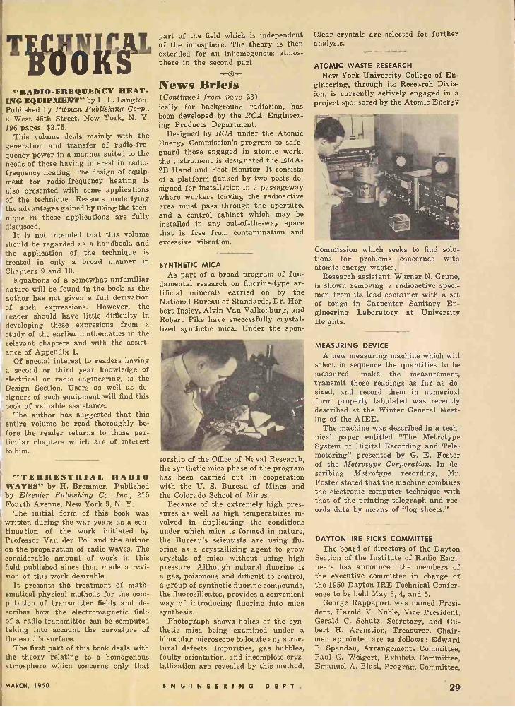
"RADIO -FREQUENCY HEAT- ING EQUIPMENT" by L. L. Langton. Published by Pitman Publishing Corp., 2 West 45th Street, New York, N. Y. 196 pages. $3.75.
This volume deals mainly with the generation and transfer of radio -fre- quency power in a manner suited to the needs of those having interest in radio - frequency heating. The design of equip- ment for radio -frequency heating is also presented with some applications of the technique. Reasons underlying the advantages gained by using the tech- nique in these applications are fully discussed.
It is not intended that this volume should be regarded as a handbook, and the application of the technique is treated in only a broad manner in Chapters 9 and 10.
Equations of a somewhat unfamiliar nature will be found in the book as the author has not given a full derivation of such expressions. However, the reader should have little difficulty in developing these expresions from a study of the earlier mathematics in the relevant chapters and with the assist- ance of Appendix 1.
Of special interest to readers having a second or third year knowledge of electrical or radio engineering, is the Design Section. Users as well as de- signers of such equipment will find this book of valuable assistance.
The author has suggested that this entire volume be read thoroughly be- fore the reader returns to those par- ticular chapters which are of interest to him.
"TERRESTRIAL RADIO WAVES" by H. Bremmer. Published by Elsevier Publishing Co. Inc., 215 Fourth Avenue, New York 3, N. Y.
The initial form of this book was written during the war years as a con- tinuation of the work initiated by Professor Van der Pol and the author on the propagation of radio waves. The considerable amount of work in this field published since then made a revi- sion of this work desirable.
It presents the treatment of math- ematical -physical methods for the com- putation of transmitter fields and de- scribes how the electromagnetic field of a radio transmitter can be computed taking into account the curvature of the earth's surface.
The first part of this book deals with the theory relating to a homogenous atmosphere which concerns only that
part of the field which is independent of the ionosphere. The theory is then extended for an inhomogenous atmos- phere in the second part.
News Briefs (Continued from page 23) ically for background radiation, has been developed by the RCA Engineer- ing Products Department.
Designed by RCA under the Atomic Energy Commission's program to safe- guard those engaged in atomic work, the instrument is designated the EMA- 2B Hand and Foot Monitor. It consists of a platform flanked by two posts de- signed for installation in a passageway where workers leaving the radioactive area must pass through the aperture, and a control cabinet which may be installed in any out-of-the-way space that is free from contamination and excessive vibration.
SYNTHETIC MICA As part of a broad program of fun-
damental research on fluorine -type ar- tificial minerals carried on by the National Bureau of Standards, Dr. Her- bert Insley, Alvin Van Valkenburg, and Robert Pike have successfully crystal- lized synthetic mica. Under the spon-
sorship of the Office of Naval Research, the synthetic mica phase of the program has been carried out in cooperation with the U. S. Bureau of Mines and the Colorado School of Mines.
Because of the extremely high pres- sures as well as high temperatures in- volved in duplicating the conditions under which mica is formed in nature, the Bureau's scientists are using flu- orine as a crystallizing agent to grow crystals of mica without using high pressure. Although natural fluorine is a gas, poisonous and difficult to control, a group of synthetic fluorine compounds, the fluorosilicates, provides a convenient way of introducing fluorine into mica synthesis.
Photograph shows flakes of the syn- thetic mica being examined under a binocular microscope to locate any struc- tural defects. Impurities, gas bubbles, faulty orientation, and incomplete crys- tallization are revealed by this method.
Clear crystals are selected for further analysis.
ATOMIC WASTE RESEARCH
New York University College of En- gineering, through its Research Divis- ion, is currently actively engaged in a project sponsored by the Atomic Energy
Commission which seeks to find tions for problems concerned atomic energy wastes.
Research assistant, Werner N. Grune, is shown removing a radioactive speci- men from its lead container with a set of tongs in Carpenter Sanitary En- gineering Laboratory at University Heights.
solu- with
MEASURING DEVICE
A new measuring machine which will select in sequence the quantities to be measured, make the measurement, transmit these readings as far as de- sired, and record them in numerical form properly tabulated was recently described at the Winter General Meet- ing of the AIEE.
The machine was described in a tech- nical paper entitled "The Metrotype System of Digital Recording and Tele - metering" presented by G. E. Foster of the Metrotype Corporation. In de- scribing Metrotype recording, Mr. Foster stated that the machine combines the electronic computer technique with that of the printing telegraph and rec- ords data by means of "log sheets."
DAYTON IRE PICKS COMMITTEE
The board of directors of the Dayton Section of the Institute of Radio Engi- neers has announced the members of the executive committee in charge of the 1950 Dayton IRE Technical Confer- ence to be held May 3, 4, and 5.
George Rappaport was named Presi- dent, Harold V. Noble, Vice President, Gerald C. Schutz, Secretary, and Gil- bert H. Arenstien, Treasurer. Chair- men appointed are as follows: Edward P. Spandau, Arrangements Committee, Paul G. Weigert, Exhibits Committee, Emanuel A. Blasi, Program Committee,
MARCH, 1950 ENGINEERING D E l T. 29
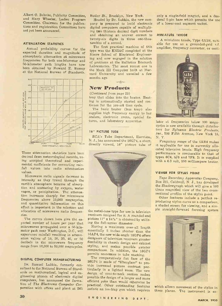
Albert O. Behnke, Publicity Committee, and Mary Wheeler, Ladies Program Committee. Chairmen for the publica- tions and registration Committees have not yet been announced.
ATTENUATION STATISTICS
Annual probability curves for the expected duration and magnitude of atmospheric attenuation at microwave frequencies for both one -kilometer and 50 -kilometer path lengths have now been obtained by Howard E. Bussey at the National Bureau of Standards.
500
450
¢ó O
400 W ú 2 } 350 WW
j 0
300
o á 250
é
UI
Q
W 2 150
QA
50
18,000
Wo.rfin,/pn, OC d0-. polo,
20,000 30000 40,000 RAP/0 FREOUEN:Y. NEOACY0LES
50 000
These attenuation statistics have been derived from meteorological records, us- ing accepted theoretical and experi- mental coefficients for converting rain- fall values into radio attentuation values.
Microwave radio signals decrease in intensity as they travel through the earth's atmosphere because of absorp- tion and scattering by oxygen, water vapor, or precipitation. The attenua- tion increases sharply for microwave frequencies above 10,000 megacycles, and quantitative information on this effect is important in the selection and allocation of microwave radio frequen- cies.
The curves shown here give the ex- pected number of hours per year that microwaves propagated over a 50 -kilo- meter path near Washington, D.C., will experience rainfall resulting in attenu- ation values of 10, 20, 30, 40, or 50 decibels in the microwave frequency range from 10,000 to 50,000 megacycles.
DIGITAL COMPUTER MANUFACTURING
Dr. Samuel Lubkin, formerly con- sultant to the National Bureau of Stand- ards on mathematical, logical and en- gineering phases of electronic digital computers, has announced the forma- tion of The Electronic Computer Cor- poration with offices and plant at 265
Butler St., Brooklyn, New York. Headed by Dr. Lubkin, the new com-
pany is prepared to build electronic digital computers capable of multiply- ing two thirteen decimal digit numbers and obtaining an answer correct to twenty-six digits in three one -thou- sandths of a second.
The first practical machine of this type was the ENIAC completed at the Moore School of Electrical Engineer- ing and now engaged in the solution of problems at the Ballistics Research Laboratories. The most recent one is the Mark III Computer built at Har- vard University and unveiled a few months ago.
New Products (Continued from page 25) tray that slides into the heater. Heat- ing is automatically started and con- tinues for the pre-set time cycle.
The basic heater (less tray) also supplies high frequency energy to bar sealers, electronic ovens, special fix- tures, and laboratory apparatus.
16" PICTURE TUBE
RCA's Tube Department, Harrison, N. J., has announced the 16GP4, a short, directly viewed, 16" picture tube of
the metal -cone type for use in television receivers designed for it. A rounded -end picture 11" x 14%" is obtained by utiliz- ing the full -screen diameter.
Having a maximum over-all length essentially 5 inches shorter than the 16AP4, the new wide-angle 16GP4 offers designers of television receivers greater flexibility in chassis design and cabinet styling, and makes possible greater compactness. In addition, the 16GP4 permits economies in tube stocking.
The comparatively flat face of the 16GP4 is made of "filterglass" to pro- vide increased picture contrast par- ticularly in a lighted room. The new design of cone -to -neck section makes possible the design of a longer and more efficient yoke than would otherwise be practical. Other outstanding features include an ion -trap gun which requires
only a single -field magnet, and a duo - decal 5 -pin base which permits the use of a lower -cost segment socket.
MINIATURE TRIODE
A miniature triode, Type 6AB4, suit- able for use as a grounded -grid r.f. amplifier, frequency converter, or oscil-
lator at frequencies below 300 mega- cycles is now available through distribu- tors for Sylvania Electric Products, Inc., 500 Fifth Avenue, New York 18, N. Y.
Frequency range of the 6AB4 makes it applicable for use in currently allo- cated television bands. High frequency performance is comparable to that of types 6C4, 6J6 and 7F8. It is supplied with a 6.3 volt, 150 milliampere heater.
VIEWER FOR STYLUS POINT
Tape Recording Apparatus Company, Box 221, Caldwell, N. J., has developed the Shadowgraph which will give a 500 times magnified view of the two cross- sectional profiles of the stylus point.
Other features include a perfect re- producing stylus curve as a comparison, a shaded screen for viewing, and a sim- ple straight -forward focusing system
which allows movement of the stylus in three planes. The instrument is en -
30 E N G I N E E R I N G D E P T. MARCH, 1950
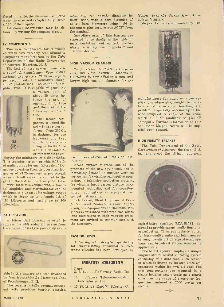
closed in a leather -finished tempered masonite case and occupies only 121h" x 15" of floor space.
Additional information may be ob- tained by writing the company direct.
TV COMPONENTS
Two new components for television receivers have recently been offered to equipment manufacturers by the Tube Department of the Radio Corporation of America, Harrison, N. J.
The first of these new components is a sound-i.f. transformer Type 206K1 designed to operate at 21.25 megacycles per second with the miniature sharp - cutoff pentode 6AU6 as sound-i.f. am- plifier tube. It is capable of providing
a voltage gain of about 35 times be- tween the grid of one sound-i.f. tube and the grid of the following sound-i.f. tube.
The second com- ponent, a sound -dis- criminator trans- former Type 207K1, is designed for use between the last
RCA sound-i.f. stage uti- 206K1 lizing a 6AU6 tube
and the sound -dis- criminator stage em-
ploying the miniature twin diode 6AL5. This transformer can provide 0.08 volt
f audio output for each kilocycle of fre- i uency deviation from its operating fre- quency of 21.25 megacycles per second, when a 1 -volt signal is applied to the g rid of the last sound-i.f. amplifier tube.
With these two components, a sound- i.f. amplifier and discriminator can be designed to give an audio -voltage output which is linear up to a bandwidth of 150 kilocycles and usable up to 300 kilocycles.
BALL BEARING
A Micro Ball Bearing reported to represent a 33% reduction in size from the smallest of its type previously avail -
207K1
¡,,,.-'-^---
able in this country has been developed by New Hampshire Ball Bearings, Inc., of Peterborough, N. H.
The bearing is fully ground, consist- ent with precision bearing practice,
measuring 1/4" outside diameter by 3/32" wide, with a bore diameter of 5/64", both diameters being held to tolerances plus zero, minus .0002" from the nominal.
Immediate uses of this bearing are reported to be chiefly in the fields of instrumentation and control, partic- ularly in widely used "Synchro" and "Servo" devices.
HIGH VACUUM CHAMBER
Pacific Universal Products Corpora- tion, 168 Vista Avenue, Pasadena 8, California is now offering a new and larger high vacuum chamber for the
vacuum evaporation of metals and die- lectrics.
Front surface mirrors, one of the products of the new equipment, are in increasing demand in nuclear work as periscopes, for viewing radioactive proc- essing, in television projection systems, for viewing large screen picture tubes mounted vertically, and for countless mirror applications in electrical and optical instruments.
Bob Frazer, Chief Engineer of Paci- fic Universal Products, is shown super- vising the equipment's initial tests. En- gineers confronted with problems which lend themselves to high vacuum treat- ment are invited to communicate with the company.
CASTING RESIN
A casting resin designed specifically for encapsulating subminiature elec- tronic circuits has been developed by
PHOTO CREDITS Page 3, 5, 6 DeMornay Budd, Inc.
14 Federal Telecommunication Laboratories, Inc.
15, 17, 18, 28..Carl W. Schutter Co.
Melpar, Inc., 452 Swann Ave., Alex- andria, Virginia.
Melpak IV is recommended by the
manufacturers for audio or video ap- plications where size, weight, tempera- ture, moisture, or rough handling is a problem. Especially noteworthy is the wide temperature range of the resin which is -85°F (ambiE:nt) to +320°F (hotspot). Further information on this and other Melpak resins will be sup- plied upon request.
HIGH-FIDELITY SPEAKER
The Tube Department of the Radio Corporation of America, Harrison, N. J. has announced the 15 -inch, duo -cone,
high-fidelity speaker, RCA -515S1, de- signed to provide exceptionally fine tonal reproduction. It is particularly suited for high -quality radio and television re- ceivers, low -distortion reproducing sys- tems, and broadcast station monitoring applications.
The 515S1 speaker employs a unique magnet structure and vibrating system consisting of a dual cone, each section of which is driven by its own voice coil operating within its own air gap. The two cone -sections are mounted in a single housing and vibrate as a single cone over the range of cross -over fre- quencies centered at 2000 cycles per second.
MARCH, 1950 ENGINEERING D E P T. 31

TE().1 WAVES IN RECTANGULAR WAVE GUIDES Nomograph for determining wavelength and group velocity in a guide, knowing free -space wavelength and guide width.
.5 n a rectangular wave guide for a TE,,, wave (trans- _
-100 verse electric), the electric vectors are parallel to one 6 -. _ side of the guide; the width dimension is measured at right _ angles to the electric vector. The wavelength within the _ - 80 guide and the group velocity are determined by the fol- "7
lowing equations: 8 - - 70 - - Group Velocity .9
V1 - (k/2b)' - 60 Velocity of Light - - - 1.0
Wavelength in Guide Phase Velocity - 50
- 40
30
20
15
2 - 0
z- - W 8 J W
6
- 5
4
- 3
2
Wavelength in Free Space Velocity of Light
= 1/V1 - (X/2b)' where J. = wavelength in free space in centimeters
15 b = width of the guide in centimeters -
Example: A rectangular wave guide with a width of 10 centimeters has a radio -frequency wave of 10 centimeters (free space wavelength) fed into it. A straight line con- necting 10 on the GUIDE WIDTH scale with 10 on the WAVELENGTH IN FREE SPACE scale will intersect the RATIO scales
at
and
Wavelength in Guide Wavelength in Free Space
Group Velocity Velocity of Light
w o 7 C)
z
x CD
z w J w > 4
w v 4 CL Oc tn
W 22.5-
E 1.5- z -
o .4
.7
-.8
o IL' 1.01 .99
cr ell
1.001
o H
.995 cc
.999
1.15
.866
2
3
S
6
8
O -
20
30
40
60 Courtesy of Federal Telephone and Radio Corporation.
e
32 ENGINEERING D E P T. MARCH, 1950
YOU Neèd M
Radio Parts and Equipment ...
16 Range Meter
Speake Tester Continuity Tester
generator. 6 -Tube Radio
ALL KITS ARE YOURS TO KEEP Each of the hundreds of Radio parts and other items I send my students is theirs "for keeps.' You may use this equipment In your Radio and Television service work and save many dollars by not having to buy expensive "ready- made" test equipment. Each of my 8 kits will help you advance and learn important steps in Radio and Television servicing.
CALVIN SKINNER of New Orleans, La. tells us he makes 85 to 810 In spare time re- pairing radios. He Is now also working with his own Television set.
My Training Includes:
Radio Servicing Television
F MFrequency Modulation
Public Address and High
Frequency Applications
IIRAY9E RRY March, 1950
LOREN D. SAUCIER of Coloma. Mich. re- ports that my training has made It possible for him to repair large numbers of Radio and Television receivers.
NOW IS THE TIME To Get Into This Fast Growing Industry-Prepare For A Fine Paying Job Or Your Own Business! If you want to get into Radio -Television and Electronics .. . you owe it to yourself to get the facts about my training. I have trained hundreds of men to become outstanding service tech- nicians-and I'm ready to do the same for you. Whether your goal is a fine paying job in one of Radio's many branches- or a successful Radio and Television business of your own-you need the kind of training I oferl My training is practical and down to earth. YOU NEED NO PREVIOUS EXPERIENCE. You'll be astonished at your rapid progress. I start you with. basic fundamentals and give you plenty ¿I practical shop -bench training with many kits of parts I send you. This is the training that sticks with you and makes money hr you on the job!
Get Paid For Spare Time While Learning Soon after you start training I send you my famous BUSINESS BUILDERS that show you how to make money in spare time doing interesting Radio jobs. Look at the useful and valuable equipment you get while training with me (illustrated at left)-I send you these 8 big kits of Radio parts and equipment and help you build step-by-step a power- ful 6 -tube superhet radio, a 16 -range test meter, plus other mighty. useful equipment for Radio and Television servicing. You will perform over 175 fascinating experiments While training. You will learn about Television-so that you will be qualified to step into this fast growing, profitable field. I also send you many valuable service manuals, diagrams and my book telling exactly how to set up your own Television and Radio shop. I want you to learn all about my training-and that is why I urge you to clip and mail the coupon below for my two big FREE Radio books. I employ no salesmen-and nobody will call on you. The important thing is to act now and get the facts.
HAVE A BUSINESS OF YOUR OWN
A profitable Radio and Television Service Shop may be started with little capital. I will show you how to get started and how to build your small business. At left is pictured one of my graduates, Mr. Merrit C. Sperry of Fairmont, Minnesota in his own shop. The way is also open for you to build a good - SERVICE BUSINESS FOR YOURSELF.
RADIO AND TELEVISION INDUSTRY BOOMING
You couldn't pick a better time to get into Radio -Tele- vision and Electronics. New Television stations are going on the air to serve every major city-hundreds of new AM and FM Radio broadcasting stations are also on the air to serve practically every community in America. All this creates new and bigger opportunities for the trained man who knows Radio -Television and Electronics. Good Radio and Television service men are needed NOW!
- - These Two Big F REE
Rat TR ORE1
Ise ` Radio Books Eii, EE IL
Just mall coupon for a FREE sample Sprayberry Lesson and my big FREE book, "How To Make Money In Radio -Television and Electronics." Learn why my really practical training Is best of all for you. Discover what's ahead for you in the fast moving Radio -Television and Elec- tronics Industry. No obligation. Don't delay-the future Is too important to you.. Mail the coupon now-and count on me for fast action.
A C A D E M Y OF R A Dt O 11I N. CANAL, DEPT. 25-G. CHICAGO 6, §611
VETERANS THIS TRAINING
AVAILABLE
TO YOU UNDER
THE G.I. BILL
SPRAYBERRY ACADEMY of RADIO, Dept.25-G 111 North Canal St., Chicago 6, III. Please rush my FREE copies of "How To Make Money In Radio - Television and Electronics" and "How To Read Radio Diagrams and Symbols."
Name Age
Address .
City.. State
( ) Check here if you are a Veteran.
19