march 17, 2011 permits & enforcement 250 william howard ... · march 17, 2011 mr. paul r....
TRANSCRIPT
Air Products and Chemicals, Inc.7201 Hamilton BoulevardAllentown, PA 18195-1501Telephone (610) 481-4911
March 17, 2011
Mr. Paul R. TedtmanHamilton County Department of Environmental ServicesPermits & Enforcement250 William Howard Taft Road, 1st FloorCincinnati, OH 45219-2660
Subject: Middletown Cogeneration FacilityMiddletown, OHBest Available Technology Assessment
Dear Mr. Tedtman:
As required by OEPA regulation, Air Products and Chemicals, Inc. (Air Products) is providing the attached Best Available Technology (BAT) assessment regarding its proposed Middletown Cogeneration Facility.
Please contact me if you have any questions regarding this submittal. Thank you.
Sincerely,
Frederick LashAir Products and Chemicals, Inc.North American Environmental GroupLead Environmental Specialist

Page 1 of 15
Middletown CogenerationControl Technology Assessment
1. Project Design Basis
The Middletown Cogeneration project will be installing a combustion turbine and two auxiliary boilers to recovery energy from blast furnace gas at the AK Steel Middletown, OH integrated steel facility. Associated with the cogeneration project will be other minor air sources such as the cooling tower, acid tanks and roadway/parking fugitive emissions and flare for emergency use. The OEPA regulations (OAC 3745-31-05) require the application of “best available technology” (BAT) be applied on non-exempt new stationary sources. The following sections discuss how the Middletown Cogeneration project meets this requirement.
2. BAT as it Relates to New Source Performance Standards.
New Source Performance Standards (NSPS) have been developed by the US EPA for specific source categories. These standards are codified in the Code of Federal Regulations (CFR) under Part 60 (40 CFR Part 60). Those standards that apply to this project are noted below:
Subpart A – General Provisions Subpart Db (Standards of Performance for Industrial-Commercial-Institutional Steam
Generating Units) – applicable to the new boilers. Subpart KKKK (Standards of Performance for Stationary Combustion Turbines) –
applicable to the combustion turbine.
Subpart KKKK was recently promulgated on July 6, 2006 while subpart Db was revised on June 13, 2007 and again on January 28, 2009. Subpart KKKK regulates emissions of NOx and SO2, while Subpart Da regulates NOx, SO2 and Particulates (PM). The project will utilize technology to comply with applicable limits from these recent federal best demonstrated technology regulations and proposes that this constitutes BAT for these pollutants.
3. BAT as it Relates to MACT Standards.
National Emission Standards for Hazardous Air Pollutants (NESHAP) have been developed by the US EPA for specific source categories. These standards are codified in the Code of Federal Regulations (CFR) under Part 63 (40 CFR Part 63). Those standards that apply to this project are noted below:
Subpart YYYY (National Emission Standards for Hazardous Air Pollutants for Stationary Combustion Turbines) – applicable to the combustion turbine.
Subpart DDDDD (National Emission Standards for Hazardous Air Pollutants for Industrial, Commercial, and Institutional Boilers and Process Heaters) - applicable to the new boilers.

Middletown CogenerationControl Technology Assessment
Page 2 of 15
Subpart YYYY was recently promulgated on March 5, 2004 and the most recent revision was on April 20, 2006. Subpart DDDDD was promulgated on September 13, 2004, was most recently signed by the EPA Administrator on February 21, 2011. Subpart YYYY exempts diffusion flame gas-fired turbines from its emission limitations. Subpart DDDDD specifically exempts boiler or process heater units that receive 90 percent or more of volume of fuel (based on an annual average) from blast furnace gas. Therefore, the project will utilize technology which comply with applicable limits from these recent federal best demonstrated technology regulations and proposes that this further constitutes BAT for these pollutants.
4. Recent Permits Issued for Blast Furnace Gas (BFG) Combustion Sources.
There are limited recent permits for sources burning BFG. As stated, there are no turbines in the United States that currently burn BFG. The project was able to identify two recent permits issued for boilers that burn BFG. The emission rates in lb/MMBtu are provided below for comparison to the Middletown Cogeneration project.
Recent Permits for BFG BoilersArcelor Mittal 1 USS 2 Middletown Cogeneration
East Chicago, IN Granite City, IL Middletown, OH561 MMBtu/hr 505 MMBtu/hr 700 3 MMBtu/hr
lb/MMBtu lb/MMBtu lb/MMBtuNOx 0.050 0.05 0.10CO 0.138 0.15 0.11PM 0.050 0.1 0.01
1 August 2010 Draft permit 2 July 2008 Final permit3 Two units - each is rated at nominal 350 MMBtu/hr
5. Evaluation of BAT to Middletown Cogeneration Sources
The following sections discuss how the turbine and boilers comply with the OEPA BAT requirement for each relevant pollutant.
5.1. Particulate (PM/PM10/PM2.5) Control
In promulgating both Subparts Db and KKKK, EPA determined that particulate emissions from gas-fired units were not a concern and did not propose limits for particulates from gas-fired sources.
Emissions of particulate matter (PM), particulate matter less than 10 micrometers in diameter (PM10) and particulate matter less than 2.5 micrometers (PM2.5) from combustion results from inert solids (ash) contained in the fuel, unburned fuel hydrocarbons which agglomerate to form particles and in the turbine from formation of ammonia sulfates from the SCR system.
Middletown CogenerationControl Technology Assessment
Page 3 of 15
Clean fuels are required for combustion turbines in order to prevent damage to the turbine blades (and other high-precision turbine components). Therefore, the project will utilize a wet electrostatic precipitator (ESP) to remove potential particulate from the BFG, prior to combustion in the turbine. The boilers, though not as sensitive as a turbine, do require clean fuels to prevent fouling of the burners and the AK water scrubber provides this cleansing of BFG before combustion in the boilers. Natural gas is an inherently clean fuel with little to no particulates.
We are not aware of any add-on particulate controls utilized for a gas-fired combustion system. Neither an ESP nor fabric filters are considered to be technically feasible options for controlling emissions after combustion turbine or boilers because of the high exhaust flow rates and low particulate loading associated with turbine exhaust. A review of the EPA RBLC database showed no listing of any post combustion control of particulates for combustion turbines or gas-fired boilers.
Finally, both the ArcelorMittal and US Steel facilities have much higher emission rates (lb/MMBtu) and annual tonnages for particulates compared to the Middletown project (See Table 2 above). Both these projects were recently permitted and determined that no add-on particulate controls were warranted.
5.2. Nitrogen Oxides (NOx) Control for Combustion Turbine
For the turbine, the project will comply with the NOx limit in Subpart KKKK to demonstrate BAT. In addition, the project has chosen to install SCR to further reduce NOx emissions below Subpart KKKK levels. SCR is the most effective control technology for NOx on combustion turbines.
5.3. Nitrogen Oxides (NOx) Control for Boilers
For the boiler, the project will comply with the applicable NOx requirements in Subpart Da and OAC rule 3745-110-03(D) NOx - Reasonably Available Control Technology (RACT) to demonstrate BAT.
The boilers are specifically being designed to reduce NOx while combusting the primary fuel –BFG. Combustion of BFG in boilers has inherently lower NOx levels than natural gas and other fuels. These inherently lower NOx levels have made add-on NOx controls not necessary or practical for BFG boilers.
Commercial use of selective non-catalytic reduction (SNCR) has never been applied on a package boiler. SNCR has to be applied in a certain temperature region and have a fairly large residence time in that region for the reactions to occur properly. The size/structure and furnace configuration of package style boilers does not typically allow for a the long residence time in the proper temperature zone, so in the majority of cases the reactions could not come to completion for NOx reduction while maintaining reasonable levels of ammonia slip. Finally, the
Middletown CogenerationControl Technology Assessment
Page 4 of 15
NOx levels for these units are already at the levels typically achieved (0.1 lb/MMBtu) by SNCR and therefore SNCR would not achieve any lower emission rate.
Also, the project is not aware of any application of SCR on a BFG fired boiler as these units have inherently lower NOx levels compared to other gas-fired units.
5.4. Sulfur Dioxide (SO2) Control
The combustion of BFG (and to a much lesser extent natural gas) creates sulfur dioxide by the oxidation of the sulfur species in the fuel. SO2 emissions from any combustion process are directly related to the sulfur content of the fuel being combusted. Emissions can be controlled either by limiting the sulfur content of the fuel or by scrubbing the SO2 from the exhaust gas.
The BFG sulfur is mostly carbonyl sulfide (COS) – approximately 95%, with the remainder being H2S. For post combustion the sulfur will be in the form of SO2.
5.4.1. Sulfur in Blast Furnace Gas (BFG) Basis
At 100 ppmvd total sulfur (as H2S and COS), the baseline BFG flow to the gas turbine contains approximately 0.8 tons per day of contained sulfur as S (based on 578 tons of SO2 from turbine). This is one of the single most important parameters in selecting viable sulfur removal technologies, often much more important than sulfur concentration. Technologies like LO-CAT, for example, have been demonstrated to have >95% removal with 50 to 100,000 ppmv (or more) sulfur in the feed stream. Feasibility breakpoints for sulfur removal tend to be more dependent on the mass flow of sulfur in the gas stream rather than the concentration.
Sulfur removal is not commonly done on BFG prior to combustion; we are unaware of any commercial steel mill that removes sulfur from BFG prior to combustion. But small scale sulfur removal technology does exist, most likely at great cost and substantial process risk.
In addition to the mass and concentration of sulfur, the chemical form of sulfur present is very important to selecting appropriate control technologies. Based on the data available, there is a wide variation in the ratio of H2S to carbonyl sulfide (COS) in AK Steel BFG. In a typical BFG stream, most of the sulfur will likely be in the form of COS. Of the nine samples taken by Air Products in October 2008, more than 90 mole% of the sulfur was COS. However, in some BFG sampling conducted by AK Steel over 50% of the sulfur was H2S. Any technology considered must be capable of removing COS as well as H2S, or the COS must be hydrolyzed to H2S. Most sulfur removal technologies are much more effective for H2S than for COS.
5.4.2. Potential Pre-Combustion Control Technologies
An extensive search for sulfur removal technologies, including scavengers, LO-CAT, Shell Paques, SulFerox, CrystaSulf, was performed. The following provides an evaluation of the technical feasibility and operational issues with each of the various technologies.
Middletown CogenerationControl Technology Assessment
Page 5 of 15
COS HydrolysisAs stated, COS hydrolysis will not remove sulfur, but is a necessary step in the control process as the controls considered require the conversion of COS to H2S. COS hydrolysis units are typically effective in the 300 to 1000 ppmv sulfur range, more concentrated than the BFG subject stream. Typically, COS is hydrolyzed in a fixed-bed catalytic reactor with steam, at temperatures in the 350° to 400° F range. In addition to the fixed-bed reactor, pre-heaters, and exit gas cooling would be required. Because of the relatively high gas volumetric flow rate, this reactor would need to be quite large (>2500ft3) and therefore quite costly. While this is a demonstrated technology, these units have been notorious for catalyst poisoning due to chlorides and entrained liquids in the feed stream. The costs to convert COS to H2S in order to remove sulfur is the same regardless of H2S removal technology selected. The cost for a COS hydrolysis system was developed and is discussed below and tables 2A and 2B in Attachment 1. The annualized cost for this system is approximately $2 million dollars and this alone results in a cost in excess of $6,000 per ton of sulfur conversion (or $3,681 per ton of SO2 without any removal –just to convert COS to H2S).
Liquid and Solid ScavengersScavengers can be very effective removing H2S, although very few of them work on COS. This technology is often used on smaller exhaust flow streams for the removal of 100 ppmv or more of sulfur. Merichem shows a range of 1-6 MMSCFD for scavengers equipment cost analysis. Scavenger systems are generally eliminated from viable control options for streams above 100-300 lbs/day of contained sulfur regardless of gas flow rate or sulfur concentration. While flow has some impact on capital costs, the operating costs are largely due to the consumption of scavenger media.
Scavengers are rarely used where the sulfur (as S) that needs to be removed is more than a few hundred pounds a day, due to cost reasons. All of the scavengers that the project is aware of are single use; they cannot practically be regenerated. This means once the scavenger is saturated with sulfur, it must be changed out and land-filled. Even the most effective scavenger has limited capacity for sulfur – rarely more than 0.2-0.25 lbs of sulfur per pound of scavenger. At 1800 lb/day of contained S, we would consume in the range of 7000-9000 lbs per day of scavengers. This is costly and generates more than 1000 tons/year of solid waste which must be land-filled. Merichem suggests a media cost of $3.50/lb S for solid scavengers. That alone represents $7000 per ton S or $3500 / ton SO2 removed. This is only the reagent cost and does not include the following:
Capital and operating costs for COS hydrolysis – approximately $2,500 per ton of SO2 –for conversion to H2S not removed.
Capital and other operating costs for scavenger system. Waste disposal costs.
Liquid scavengers are even more expensive, costing approximately $5,000 per ton of reagent. Additional capital and operating costs added to this value will make this control not cost effective. Also, liquid carryover into the gas turbine could be a problem, with added liquid carryover controls further driving up the cost of this technology.
Middletown CogenerationControl Technology Assessment
Page 6 of 15
Shell Paques / THIOPAQThis is a biological process that uses sulfur oxidizing bacteria to convert H2S to solid sulfur. It does little COS removal (minimal data available) and therefore would require a hydrolysis system in conjunction with this process to be effective. It is much less demonstrated than LO-CAT on syngas streams and has fewer installations overall. The biological aspect is a major concern. It has lower chemical costs than LO-CAT but no other advantages that can be demonstrated. There are potential unknown technical risks due to a lack of experience in syngas relative to LO-CAT.
CrystaSulfThis process is by far the least demonstrated of the sulfur technologies we have evaluated. It is basically a liquid-phase Claus process in a hydrocarbon medium (as opposed to aqueous for LO-CAT, THIOPAQ, etc.) It was developed to eliminate perceived operating problems with LO-CAT and others, many of which are now solved. Compared to LO-CAT, this process is substantially more complex and requires a source of SO2 as a reagent, (which is a very toxic gas, hazardous to ship and costly to generate on site). Thus, it will be more costly to implement than LO-CAT. There are no known units operating today, but at least two commercial plants were built and subsequently shut down. It has never been commercially demonstrated on syngas. It has some potential advantages but these do not out-weigh the lack of experience. And finally it does not remove COS. Based on the fact that we are not aware of any existing full-scale installations, this process is not commercially feasible and will not be considered further.
LO-CATLO-CAT is an iron redox process from Merichem with well over 100 plants in operation. They have designed plants with as low as 40-100 ppmv H2S in the feed. The Middletown Cogeneration unit would be the largest gas flow for any LO-CAT plant at 213 MMSCFD, but they have demonstrated a plant at 201 MMSCFD. They routinely achieve 99+% sulfur removal, with exit levels of H2S often in the range of 1-5 ppmv. LO-CAT does not remove COS; and therefore hydrolysis would be required. It produces a solid sulfur product that can be land-filled. It is likely that Merichem would support the use of LO-CAT for BFG sulfur removal and may even provide a process warranty.
Based on operating experience, commercial availability and process complexity, none of these technologies would be BAT for sulfur removal for the Middletown Cogeneration facility. Of these technologies, LO-CAT is by far the best demonstrated on syngas streams from various sources (but not BFG). Merichem has provided a full experience list. LO-CAT was chosen as the best demonstrated and the most cost-effective removal process, relative to all the other technologies. Based on the projects initial evaluation, no alternative would have a lower potential capital and operating cost for this application.
To further the investigation, we have obtained a detailed budgetary quotation on the LO-CATprocess.
5.4.3. Cost Evaluation of LO-CAT

Middletown CogenerationControl Technology Assessment
Page 7 of 15
A cost evaluation for Sulfur removal was completed utilizing the LO-CAT technology based on preliminary Sulfur removal process information for the Middletown project. To conduct the cost analysis we used the format and recommended factors from OEPA Engineering Guide 46 –“Guidance for Estimating Capital and Annual Costs for Air Pollution Control Systems.” From Guide 46 we utilized factors for a Gas Absorber (which the Sulfur removal system mostly closely resembles). All equipment costs were based on scaling from information obtained from previous projects and/or studies ducted by Air Products. The installation costs were based on utilizing the overall install factor of the plant based on the completed design estimate for the overall Middletown Cogeneration Facility.
Various components are needed for the capital and operating cost analysis such as:1) Taking the stream from the interstage of the Fuel Gas Compressor2) Running it through a trim heater to get the temperature close to 300°F3) Injecting steam into the gas stream to provide the necessary water for hydrolysis to occur4) Running through a COS Hydrolysis catalyst in order to convert the COS to H2S5) Reducing the temperature to ~120°F via an economizer and trim cooler in order to get the
necessary temperature to run the stream through the LO-Cat H2S removal system6) Running the stream through the LO-CAT (Iron-Redox) system to remove up to 95% of
the Sulfur present in the gas stream7) Sending the stream back to the economizer to elevate the gas temperature to the
appropriate temperatures8) Sending the stream through a trim steam heater before introduction back into the
compressor. This is necessary in order to maintain the temperature out of the FGC (GT inlet temperature)
The operating costs were based on the following:1) Additional operating labor due to the complex system as well as corresponding site
overhead2) COS catalyst replacement every 3 years3) Chemical usage in the LO-Cat system4) Annual maintenance cost for the additional equipment5) Property Tax / Insurance / G&A and Ops Overhead impacts due to increase capital /
operating costs
Annual performance impacts were based on the following:1) Increase in Fuel Gas Compressor power requirements due to increased pressure drop
from the new equipment2) Increased plant auxiliary power for the operation of the LO-CAT system3) Steam usage for the steam heater which is no longer available for power generation
resulting in loss revenues4) Steam usage for the injection of steam of hydrolysis which is no longer available for
power generation resulting in loss revenues
The results of this analysis are presented in Attachment 1. In summary, the cost to remove the Sulfur is estimated to be $28,632 per ton SO2 removed. This is based on approximately 578tons/year of Sulfur as SO2.basis and removal of 549 tons (Note – the 578 tons of SO2 is the
Middletown CogenerationControl Technology Assessment
Page 8 of 15
equipment potential for the turbine based on 100 ppmvd S in BFG case. This is a maximum case for conservative purposes. This cost far exceeds is way beyond any value that would be economically feasible for this project.
5.4.4. Post Combustion Control
The only add-on control technology currently utilized to control sulfur dioxide emissions from combustion sources is a flue gas desulfurization system. Flue gas desulfurization (FGD) is a term that may refer to any chemical process used to remove SO2 from combustion exhaust gases. An FGD application usually operates by contacting the exhaust gas with an alkaline slurry or solution that absorbs and subsequently reacts with the acidic sulfur components. FGD technologies may be wet, semi-dry, or dry depending on the state of the reagent as it leaves the absorber vessel. Wet, calcium-based processes, which use lime (CaO) or limestone (CaCO3) as the alkaline reagent, are the most common FGD processes in utility boiler applications but are impractical for the Middletown Cogeneration project.
FGD (wet or dry) as an add-on control would not be feasible for use at the facility. FGD applications are mass-transfer processes that rely on concentration differentials to absorb SO2
from a gas stream into the liquid or onto a solid. Because of the inherently low concentrations of SO2 (under 150 ppm) in BFG compared to coal plants (SO2 concentrations in the 1,000 to 10,000 ppm) where these technologies have been utilized, these scrubbing processes would not be effective. The SO2 levels from the Middletown Co-Generation project are significantly less than the “controlled” levels from most FGD systems.
Another obvious problem is the generation of a waste stream (solid and/or wastewater). Currently there is a very minimal water discharge that will be sent to the local wastewater treatment facility. With a wet scrubber the obvious problem is the generation of a water waste stream that would require its own wastewater treatment system. Finally, operating any FGD system would add a large energy penalty that would make the project economically not viable.
There are no pre or post combustion controls that are feasible for SO2 control. The ArcelorMittal and US Steel facilities have similar emission rates for SO2 and they were recently permitted with no SO2 controls.
5.4.5. Summary for SO2
Based on the evaluation of available sulfur removal process, the project does not believe any of the systems are an engineering viable choice for this specific project. All of the processes have some technical, energy or environmental issues with trying to apply them to the BFG process stream.
Ignoring the engineering issues, we have developed a cost analysis for the most cost-effective of the technologies, the LO-CAT process. The cost per ton of SO2 removed would be at least $28,632. This cost far exceeds any value that would be Best Available Technology or even economically feasible for this project.

Middletown CogenerationControl Technology Assessment
Page 9 of 15
Also as part of this evaluation, it is documented that any sulfur control system would require a COS hydrolysis system and that the cost of this process step on an annualized basis would be approximately $2 million dollars and this alone results in a cost in excess of $6,000 per ton of sulfur conversion (or $3,681 per ton of SO2 without any removal).
5.5. Carbon Monoxide (CO) Control for Boiler
The Project is proposing to utilize good combustion practice as the control for CO emissions from the boilers. This is the highest level of control identified for any similar projects that have not had to undergo PSD or NSR review. Also the 0.114 lb/MMBtu proposed for the Middletown Cogen unit is one of the lowest levels found for BFG boilers and is lower than units with similar low NOx levels such as the US Steel Granite City (permit issued January 30, 2008) and the AcelorMittal, East Chicago facility(draft permit issued in August 2010).
5.6. Carbon Monoxide (CO) Control for Combustions Turbine
Based on a review of the U.S. EPA’s RACT/BACT/LAER Clearinghouse database and URS’s recent permitting experience, two CO control options were examined for the proposed combustion turbines: 1) catalytic oxidation; and 2) good combustion practices. The Project is proposing to utilize good combustion practice as the control for CO emissions. This is the highest level of control identified for any similar projects that have not had to undergo PSD or NSR review, or synthetic minor limits to avoid such review.
5.6.1. CO Control EvaluationAs identified, there are only two options for control of CO emissions from the combustion turbine: 1) catalytic oxidation; and 2) good combustion practices and each is discussed below.
Catalytic OxidationIn catalytic oxidation, exhaust gas passes through a catalyst bed (typically platinum/rhodium) where oxidation of CO to CO2 takes place. The catalyst has an operating temperature in the range of 500F - 1200F and an optimum temperature range of 650F - 1100F. Control efficiency increases with increasing temperature from approximately 650F - 1100F, but additional increases in temperature above 1100F have no positive effect on removal efficiency. The operating temperature of the catalyst must be maintained below 1200F to prevent rapid thermal aging of the catalyst and possible sintering, both of which lead to reduced catalyst activity and diminished performance. Based on published data, catalytic oxidation is capable of reducing CO levels by 70 to 90 percent from natural gas-fired turbines.
Oxidation catalysts are nonselective and will oxidize other compounds present in the exhaust gas stream. For example, SO2 will be further oxidized to reactive sulfur trioxide that will lead to corrosive conditions within and downstream of the catalytic oxidation system. Fuels with any appreciable amounts of sulfur commonly have corrosion issues.
Combustion ControlsCO is formed in the combustion process due to the incomplete oxidation of the carbon in the fuels. Good combustion practice involves combusting the fuel as efficiently and completely as
Middletown CogenerationControl Technology Assessment
Page 10 of 15
possible to reduce potential formation of CO emissions. Good combustion practices or combustion control involve utilization of proper air-to-fuel ratio and turbine design to achieve good mixing and turbulence, adequate temperature and sufficient residence time.
Add-on controls for CO are not practical for this project due to the presence of sulfur in the exhaust gases and use of selective catalytic reduction (SCR) to control NOx. Oxidation catalysts are nonselective and will oxidize other compounds present in the exhaust gas stream. Theaddition of an oxidation catalyst would cause a roughly 25% increase in ammonium bisulfate formation (sulfur trioxide reacting with the ammonia used within the SCR). Ammonium bisulfate is a very fine, sticky potentially corrosive particle. The issues with this added ammonium bisulfate formation are:
The increased levels of ammonium bisulfate would foul the cold end of the HRSG and cause severe operational problems. This would lead to higher pressure drops across the system and a requirement to conduct periodic inspections and cleaning to prevent system downtime.
The ammonium bisulfate will impact SCR design and performance, since the SCR must be located downstream of the CO catalyst. The formation of ammonium salts within the SCR catalyst will, at a minimum, mask the active sites of the catalyst and will reduce the activity of the catalysts. Surface fouling on the SCR can be reversed by cleaning, however; formation of bisulfate within the active pours of the catalyst can causemacroscopic plugging which will irreparably damage the catalyst.
When combined with moisture, the ammonium salts are very corrosive and will cause damage and shorten the life of the heat exchangers.
The addition of CO catalyst would obviously increase Greenhouse Gas (GHG) emissions of CO2. Given the proposed cap and trade rules for GHG, this would not only be an environmental issue, but would impose a cost penalty on an annual basis.
Based on the evaluation of oxidation catalyst, the project does not believe this is an engineering viable choice for this specific project. There is technical, energy and environmental issues with trying to apply the catalyst to the BFG process stream (with an SCR).
5.6.2. Cost Evaluation
Although the Project does not believe it is viable to install an oxidation catalyst on this system, we have developed a cost analysis for applying an oxidation catalyst on the gas turbine. We have tried to incorporate engineering design features to maintain the required reliability of the HRSG and SCR system based on recommendations from the HRSG and catalyst vendors as to potential plugging/corrosion issues.
As with the sulfur analysis, to conduct the cost analysis for oxidation catalyst, we used the format and recommended factors from OEPA Engineering Guide 46 – “Guidance for Estimating Capital and Annual Costs for Air Pollution Control Systems.” From Guide 46 for the oxidation catalyst removal system, the closest operating unit in the Guide 46 was a Carbon Adsorption system. Average cost factors for this system were utilized.
Middletown CogenerationControl Technology Assessment
Page 11 of 15
To thoroughly address the questions, we asked both the Burns and McDonnell (engineering firmcontracted by Air Products and Chemicals, Inc.) and potential vendors to confirm the design basis and operating issues associated with the installation of an oxidation catalyst for this particular system. The basis for the majority of the responses is a January 27, 2011 email from Vogt (oxidation catalyst vendor) to Burns and McDonnell. Burns and McDonnell utilized these responses, along with their extensive experience with oxidation catalyst systems to compile the appropriate cost and operating factors.
The sources of cost information utilized for this effort is consistent with evaluations that are typically performed for this type of large capital projects, including the use of values from Engineering Guide no. 46, to help assist in making decisions on project scope and corresponding financial impacts. These costs can generally be classified into three categories: 1) Basic Equipment, 2) Facilities/buildings, and 3) Annualized operating costs. The basis and assumptions used are summarized below:
Basic Equipment
The basic equipment capital cost is estimated at $1,548,760. This is based on a capital cost of $648,760 for the CO catalyst, $700,000 additional cost for HRSG modifications to facilitate clean-out, and $200,000 increased cost for the SCR catalyst system modifications. These estimates are based on the Vogt email. The $200,000 is documented in the February 3, 2011 email from Burns & McDonnell.
Site Preparation and Facilities/buildings
Site PreparationThe $100,000 site preparation cost was calculated as 1.5% of a $6.7 Million total project site prep cost. Total site prep cost was determined by ACPI from contractor quotations. The 1.5% factor is based on a prorated share of total project capital adjusted for specific installation complexity.
Facilities/buildingsPer vendor information, the CO catalyst footprint would be approximately 17 ft. x 5 ft and this appears in an email (see Attachment 1) from Burns and McDonnell. To accommodate this amount of catalyst storage, Air Products estimated it would require an additional 10 ft by 20 ft of warehouse storage.
The building cost estimate of $158/sq ft. based on the final APCI construction cost estimate as prepared by Burns & McDonnell. Given that final contractor bids have not been awarded, detailed economic information is still proprietary at this time.
Engineering Guide 46 Adjustment FactorsAn adjustment factor from Engineering Guide 46 of “2” instead of “1” was used for Engineering/supervision due to the high end of Custom equipment.
Middletown CogenerationControl Technology Assessment
Page 12 of 15
For instrumentation and controls, an adjustment factor of “1.0” was selected from the list as being most representative as automated controls are utilized as this CO catalyst is new equipment for Air Products and is a large system compared to the definition attached to the 0.5 number (Small-capacity standard equipment, duplication of typical system).
An adjustment factor of “2” was used for the Construction fee because the overall contracting strategy for development of the Middletown Cogeneration facility is to utilize multiple contractors with Architect and Engineering (A&E) firm’s supervision. There will be a site prep contractor, civil, mechanical, electrical and catalyst loading contract supervised by the A&E. A factor of 2 for this type of work arrangement is conservative.
An adjustment factor of “5” was used for Contingency because, based on the definitions, the CO catalyst will need to be guaranteed of efficiencies and operating specifications which has a cost adjustment factor between 5 & 10. Utilizing 5 provides $131,250 of contingency which on the overall capital cost is only 7.7%. In reality, for this level of effort the contingency should be higher (in the 15-20% range) which would be a factor of 10 or even higher. We have adjusted this factor up to 10 which gives an overall contingency of 15% which is still low for this type of effort. The CO catalyst addition, should not add any additional cost for operators/supervision for the planned staffing of the plant.
Annualized operating costs
CO CatalystThe CO catalyst is typically guaranteed by vendors to last, in continued operation, for three years. The capital estimate basis of $625K was based on a CO catalyst volume to allow 3 years of continuous operation until replacement is required. Based on the January 27, 2011 email from Vogt the CO catalyst replacement is estimated at $370,200 ($111,060 annual).
Due to the presence of the CO catalyst an additional cost for replacing the SCR Catalyst will be required. Without CO catalyst, the 3 year SCR catalyst replacement costs are $260K on an annualized basis. Due to the increased fouling in the SCR catalyst as a result of the additional SO3 formation (due to the presence of the CO catalyst), an additional $75K worth of SCR catalyst is required to try and maintain the SCR catalyst performance at the required level. The design criteria of this plant is to combust BFG and provide steam to AK Steel, therefore high on-line availability is a requirement. The SCR catalyst replacement cost has been set at $75,000 per year.
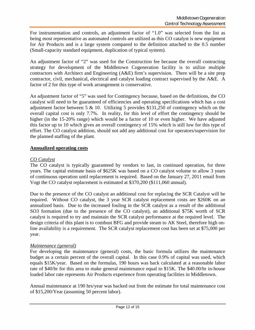
Maintenance (general)For developing the maintenance (general) costs, the basic formula utilizes the maintenance budget as a certain percent of the overall capital. In this case 0.9% of capital was used, which equals $15K/year. Based on the formulas, 190 hours was back calculated at a reasonable labor rate of $40/hr for this area to make general maintenance equal to $15K. The $40.00/hr in-house loaded labor rate represents Air Products experience from operating facilities in Middletown.
Annual maintenance at 190 hrs/year was backed out from the estimate for total maintenance cost of $15,200/Year (assuming 50 percent labor).
Middletown CogenerationControl Technology Assessment
Page 13 of 15
Because of the increased capital budgets shown in Table 3-A, the annual cost of maintenance has increased proportionally. In the latest version of Table 3-B, the labor hours calculation was eliminated and the total estimated annual labor cost was listed. Maintenance materials were estimated as 100% of the maintenance labor cost.
The annual general maintenance cost of $38,400 is based on 0.9% of the revised total capital budget of $4,262,000.
Maintenance (additional)After consulting with the catalyst vendors, Vogt has provided an estimate for CO2 cleaning for the project. From Vogt’s email dated January 27, 2011, annual inspections and cleaning is estimated between $45,000 - $80,000 and broken down as follows:
1) Annual inspection by VPI: $5,0002) Recommended Annual CO2 cleaning: $40,000-$75,000.
Maintenance materials were estimated as 100% of the maintenance labor cost with an average total HRSG cleaning cost of $62,500 per year used in the analysis.
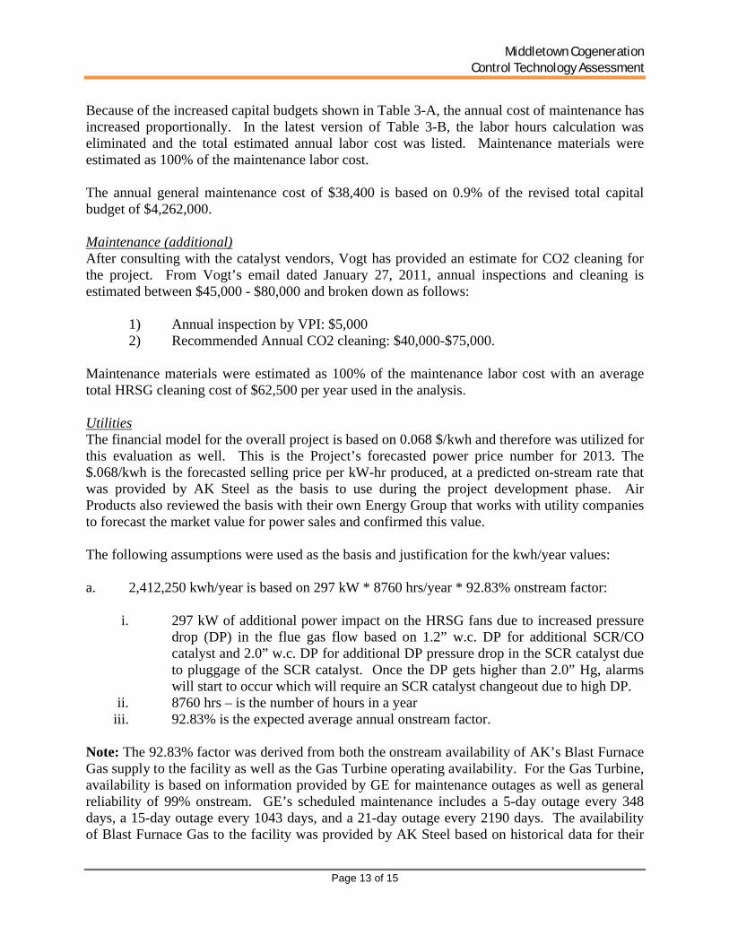
UtilitiesThe financial model for the overall project is based on 0.068 $/kwh and therefore was utilized for this evaluation as well. This is the Project’s forecasted power price number for 2013. The $.068/kwh is the forecasted selling price per kW-hr produced, at a predicted on-stream rate that was provided by AK Steel as the basis to use during the project development phase. Air Products also reviewed the basis with their own Energy Group that works with utility companies to forecast the market value for power sales and confirmed this value.
The following assumptions were used as the basis and justification for the kwh/year values:
a. 2,412,250 kwh/year is based on 297 kW * 8760 hrs/year * 92.83% onstream factor:
i. 297 kW of additional power impact on the HRSG fans due to increased pressure drop (DP) in the flue gas flow based on 1.2” w.c. DP for additional SCR/CO catalyst and 2.0” w.c. DP for additional DP pressure drop in the SCR catalyst due to pluggage of the SCR catalyst. Once the DP gets higher than 2.0” Hg, alarms will start to occur which will require an SCR catalyst changeout due to high DP.
ii. 8760 hrs – is the number of hours in a yeariii. 92.83% is the expected average annual onstream factor.
Note: The 92.83% factor was derived from both the onstream availability of AK’s Blast Furnace Gas supply to the facility as well as the Gas Turbine operating availability. For the Gas Turbine, availability is based on information provided by GE for maintenance outages as well as general reliability of 99% onstream. GE’s scheduled maintenance includes a 5-day outage every 348 days, a 15-day outage every 1043 days, and a 21-day outage every 2190 days. The availability of Blast Furnace Gas to the facility was provided by AK Steel based on historical data for their

Middletown CogenerationControl Technology Assessment
Page 14 of 15
downtime which includes a 1-day outage every 42 days as well as general reliability of 99% onstream.
The 297 kW value was calculated by multiplying the 3.2” W.c. additional pressure drop by 92.73 kW/w.c. The 92.73 kW/w.c. parameter was developed by GE to adjust the output losses of gas turbines for additional exhaust back pressure.
Additional dp: 1.2” w.c. through the SCR (ref Vogt e-mail). Up to 2” w.c. additional dP due to ammonium bisulfate salt formations plugging the tubes. The 306 kW is based on GE’s quoted reduction in kW for each 1” w.c. additional backpressure.
b. 365,818 kwh/year is based on 45 kW * 8760 hrs/year * 92.83% onstream factor
i. The 45kW is the estimated performance impact in energy loss to increase the feed water temperature from current design of 240°F to 253°F. The feedwater temperature needs to increase to maintain the flue gas above the acid gas dewpoint temperature of the flue gas which increases due to increased oxidation of sulfur from the catalyst.
c. 10,486,771 kwh/year is based on 1290 kW * 8760 hrs/year * 92.83%
i. 1290kW is estimated from the lost power generation revenue due to plant availability due to plugging/cleaning issues. We estimated an extra 1.1% downtime. Therefore estimate is based on design of 117.3 MW * 1.1% * 1000 kw/Mw.
ii. 1.1% of additional downtime is based on 2 days/year of additional downtime per year for planned inspections and CO2 spray cleans and an additional 2 days/year for unplanned downtime due to problems occurring for high pressure drop in the HRSG or other problems.
Note: The 117.3 mW value is the averaged annual net power generation capacity of the plant. This is derived per the power generated from to the Gas Turbine Generator (99.44 mW) and Steam Turbine Generator (52.91 mW), less the power consumptions in the plant (35 mW). It determines the additional power generation opportunity losses due to the increased down-time imposed by HRSG plugging/cleaning.
The four additional down-time days is based on information from Vogt and other SCR/HRSG vendors. The CO2 cleaning is included in the annual maintenance total of $80k, indicated in the spreadsheet. Vogt estimates 2-3 days to do the inspection/cleaning. Unscheduled downtime is included for unplanned outages due to high sulfur fuel slugs.
Waste DisposalThe plan is to send spent SCR catalyst for valuable metal reclamation as opposed to landfill disposal. As a result, there will be no associated catalyst disposal costs and we are removing the $15,000 charge from our initial assessment.
Middletown CogenerationControl Technology Assessment
Page 15 of 15
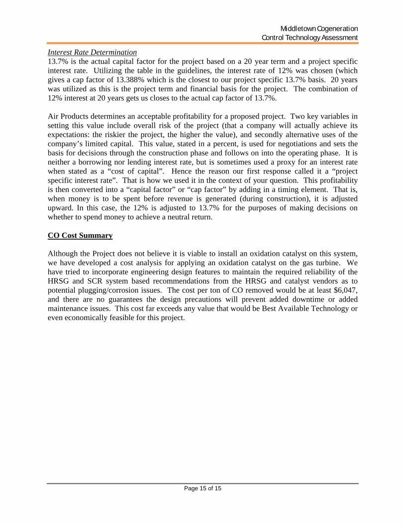
Interest Rate Determination13.7% is the actual capital factor for the project based on a 20 year term and a project specific interest rate. Utilizing the table in the guidelines, the interest rate of 12% was chosen (which gives a cap factor of 13.388% which is the closest to our project specific 13.7% basis. 20 years was utilized as this is the project term and financial basis for the project. The combination of 12% interest at 20 years gets us closes to the actual cap factor of 13.7%.
Air Products determines an acceptable profitability for a proposed project. Two key variables in setting this value include overall risk of the project (that a company will actually achieve its expectations: the riskier the project, the higher the value), and secondly alternative uses of the company’s limited capital. This value, stated in a percent, is used for negotiations and sets the basis for decisions through the construction phase and follows on into the operating phase. It is neither a borrowing nor lending interest rate, but is sometimes used a proxy for an interest rate when stated as a “cost of capital”. Hence the reason our first response called it a “project specific interest rate”. That is how we used it in the context of your question. This profitability is then converted into a “capital factor” or “cap factor” by adding in a timing element. That is, when money is to be spent before revenue is generated (during construction), it is adjusted upward. In this case, the 12% is adjusted to 13.7% for the purposes of making decisions on whether to spend money to achieve a neutral return.
CO Cost Summary
Although the Project does not believe it is viable to install an oxidation catalyst on this system, we have developed a cost analysis for applying an oxidation catalyst on the gas turbine. We have tried to incorporate engineering design features to maintain the required reliability of the HRSG and SCR system based recommendations from the HRSG and catalyst vendors as to potential plugging/corrosion issues. The cost per ton of CO removed would be at least $6,047, and there are no guarantees the design precautions will prevent added downtime or added maintenance issues. This cost far exceeds any value that would be Best Available Technology or even economically feasible for this project.

Attachment 1
Cost Tables
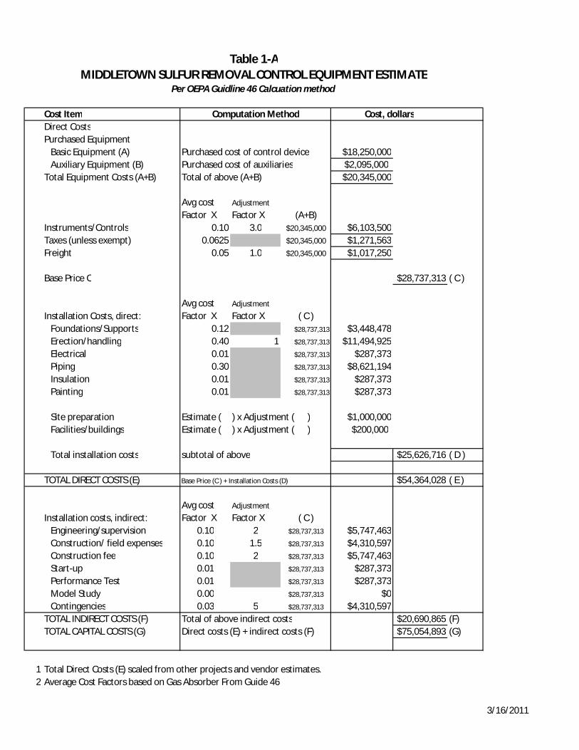
MIDDLETOWN SULFUR REMOVAL CONTROL EQUIPMENT ESTIMATE
Cost Item Computation Method Cost, dollarsDirect CostsPurchased Equipment
Basic Equipment (A) Purchased cost of control device $18,250,000Auxiliary Equipment (B) Purchased cost of auxiliaries $2,095,000
Total Equipment Costs (A+B) Total of above (A+B) $20,345,000
Avg cost Factor X
Adjustment
Factor X (A+B)Instruments/Controls 0.10 3.0 $20,345,000 $6,103,500Taxes (unless exempt) 0.0625 $20,345,000 $1,271,563Freight 0.05 1.0 $20,345,000 $1,017,250
Base Price C $28,737,313 ( C )
Installation Costs, direct:Avg cost Factor X
Adjustment
Factor X ( C )Foundations/Supports 0.12 $28,737,313 $3,448,478Erection/handling 0.40 1 $28,737,313 $11,494,925Electrical 0.01 $28,737,313 $287,373Piping 0.30 $28,737,313 $8,621,194Insulation 0.01 $28,737,313 $287,373Painting 0.01 $28,737,313 $287,373
Site preparation Estimate ( ) x Adjustment ( ) $1,000,000Facilities/buildings Estimate ( ) x Adjustment ( ) $200,000
Total installation costs subtotal of above $25,626,716 ( D )
TOTAL DIRECT COSTS (E) Base Price (C ) + Installation Costs (D) $54,364,028 ( E )
Installation costs, indirect:Avg cost Factor X
Adjustment
Factor X ( C )Engineering/supervision 0.10 2 $28,737,313 $5,747,463Construction/ field expenses 0.10 1.5 $28,737,313 $4,310,597Construction fee 0.10 2 $28,737,313 $5,747,463Start-up 0.01 $28,737,313 $287,373Performance Test 0.01 $28,737,313 $287,373Model Study 0.00 $28,737,313 $0Contingencies 0.03 5 $28,737,313 $4,310,597
TOTAL INDIRECT COSTS (F) Total of above indirect costs $20,690,865 (F)TOTAL CAPITAL COSTS (G) Direct costs (E) + indirect costs (F) $75,054,893 (G)
1 Total Direct Costs (E) scaled from other projects and vendor estimates.2 Average Cost Factors based on Gas Absorber From Guide 46
Per OEPA Guidline 46 Calcuation method
Table 1-A
3/16/2011
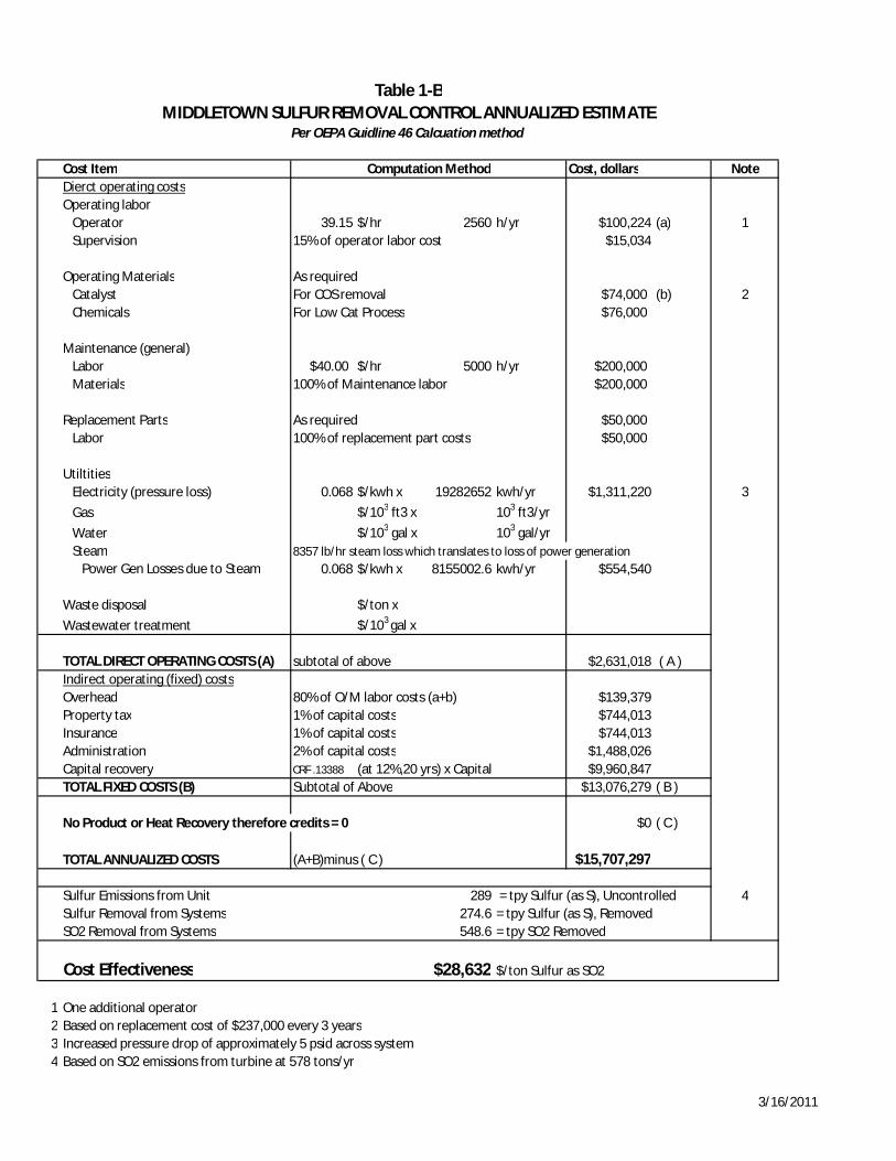
Cost Item Computation Method Cost, dollars NoteDierct operating costsOperating labor
Operator 39.15 $/hr 2560 h/yr $100,224 (a) 1Supervision 15% of operator labor cost $15,034
Operating Materials As requiredCatalyst For COS removal $74,000 (b) 2Chemicals For Low Cat Process $76,000
Maintenance (general)Labor $40.00 $/hr 5000 h/yr $200,000Materials 100% of Maintenance labor $200,000
Replacement Parts As required $50,000Labor 100% of replacement part costs $50,000
UtiltitiesElectricity (pressure loss) 0.068 $/kwh x 19282652 kwh/yr $1,311,220 3Gas $/103 ft3 x 103 ft3/yrWater $/103 gal x 103 gal/yrSteam 8357 lb/hr steam loss which translates to loss of power generation
Power Gen Losses due to Steam 0.068 $/kwh x 8155002.6 kwh/yr $554,540
Waste disposal $/ton xWastewater treatment $/103 gal x
TOTAL DIRECT OPERATING COSTS (A) subtotal of above $2,631,018 ( A )Indirect operating (fixed) costsOverhead 80% of O/M labor costs (a+b) $139,379Property tax 1% of capital costs $744,013Insurance 1% of capital costs $744,013Administration 2% of capital costs $1,488,026Capital recovery CRF .13388 (at 12%,20 yrs) x Capital $9,960,847TOTAL FIXED COSTS (B) Subtotal of Above $13,076,279 ( B )
No Product or Heat Recovery therefore credits = 0 $0 ( C )
TOTAL ANNUALIZED COSTS (A+B)minus ( C ) $15,707,297
Sulfur Emissions from Unit 289 = tpy Sulfur (as S), Uncontrolled 4Sulfur Removal from Systems 274.6 = tpy Sulfur (as S), RemovedSO2 Removal from Systems 548.6 = tpy SO2 Removed
Cost Effectiveness $28,632 $/ton Sulfur as SO2
1 One additional operator2 Based on replacement cost of $237,000 every 3 years3 Increased pressure drop of approximately 5 psid across system4 Based on SO2 emissions from turbine at 578 tons/yr
MIDDLETOWN SULFUR REMOVAL CONTROL ANNUALIZED ESTIMATETable 1-B
Per OEPA Guidline 46 Calcuation method
3/16/2011
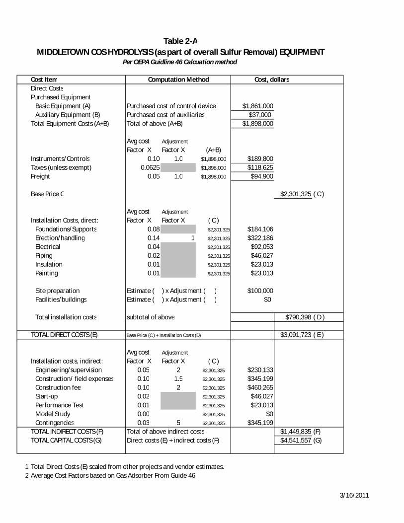
Cost Item Computation Method Cost, dollarsDirect CostsPurchased Equipment
Basic Equipment (A) Purchased cost of control device $1,861,000Auxiliary Equipment (B) Purchased cost of auxiliaries $37,000
Total Equipment Costs (A+B) Total of above (A+B) $1,898,000
Avg cost Factor X
Adjustment
Factor X (A+B)Instruments/Controls 0.10 1.0 $1,898,000 $189,800Taxes (unless exempt) 0.0625 $1,898,000 $118,625Freight 0.05 1.0 $1,898,000 $94,900
Base Price C $2,301,325 ( C )
Installation Costs, direct:Avg cost Factor X
Adjustment
Factor X ( C )Foundations/Supports 0.08 $2,301,325 $184,106Erection/handling 0.14 1 $2,301,325 $322,186Electrical 0.04 $2,301,325 $92,053Piping 0.02 $2,301,325 $46,027Insulation 0.01 $2,301,325 $23,013Painting 0.01 $2,301,325 $23,013
Site preparation Estimate ( ) x Adjustment ( ) $100,000Facilities/buildings Estimate ( ) x Adjustment ( ) $0
Total installation costs subtotal of above $790,398 ( D )
TOTAL DIRECT COSTS (E) Base Price (C ) + Installation Costs (D) $3,091,723 ( E )
Installation costs, indirect:Avg cost Factor X
Adjustment
Factor X ( C )Engineering/supervision 0.05 2 $2,301,325 $230,133Construction/ field expenses 0.10 1.5 $2,301,325 $345,199Construction fee 0.10 2 $2,301,325 $460,265Start-up 0.02 $2,301,325 $46,027Performance Test 0.01 $2,301,325 $23,013Model Study 0.00 $2,301,325 $0Contingencies 0.03 5 $2,301,325 $345,199
TOTAL INDIRECT COSTS (F) Total of above indirect costs $1,449,835 (F)TOTAL CAPITAL COSTS (G) Direct costs (E) + indirect costs (F) $4,541,557 (G)
1 Total Direct Costs (E) scaled from other projects and vendor estimates.2 Average Cost Factors based on Gas Adsorber From Guide 46
MIDDLETOWN COS HYDROLYSIS (as part of overall Sulfur Removal) EQUIPMENTPer OEPA Guidline 46 Calcuation method
Table 2-A
3/16/2011
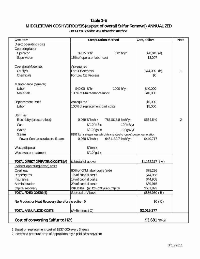
Cost Item Computation Method Cost, dollars NoteDierct operating costsOperating labor
Operator 39.15 $/hr 512 h/yr $20,045 (a)Supervision 15% of operator labor cost $3,007
Operating Materials As requiredCatalyst For COS removal $74,000 (b) 1Chemicals For Low Cat Process $0
Maintenance (general)Labor $40.00 $/hr 1000 h/yr $40,000Materials 100% of Maintenance labor $40,000
Replacement Parts As required $5,000Labor 100% of replacement part costs $5,000
UtiltitiesElectricity (pressure loss) 0.068 $/kwh x 7861013.8 kwh/yr $534,549 2Gas $/103 ft3 x 103 ft3/yrWater $/103 gal x 103 gal/yrSteam 8357 lb/hr steam loss which translates to loss of power generation
Power Gen Losses due to Steam 0.068 $/kwh x 6481130.7 kwh/yr $440,717
Waste disposal $/ton xWastewater treatment $/103 gal x
TOTAL DIRECT OPERATING COSTS (A) subtotal of above $1,162,317 ( A )Indirect operating (fixed) costsOverhead 80% of O/M labor costs (a+b) $75,236Property tax 1% of capital costs $44,958Insurance 1% of capital costs $44,958Administration 2% of capital costs $89,915Capital recovery CRF .13388 (at 12%,20 yrs) x Capital $601,893TOTAL FIXED COSTS (B) Subtotal of Above $856,960 ( B )
No Product or Heat Recovery therefore credits = 0 $0 ( C )
TOTAL ANNUALIZED COSTS (A+B)minus ( C ) $2,019,277
Cost of converting Sulfur to H2S $3,681 $/ton
1 Based on replacement cost of $237,000 every 3 years2 Increased pressure drop of approximately 5 psid across system
MIDDLETOWN COS HYDROLYSIS (as part of overall Sulfur Removal) ANNUALIZEDPer OEPA Guidline 46 Calcuation method
Table 1-B
3/16/2011
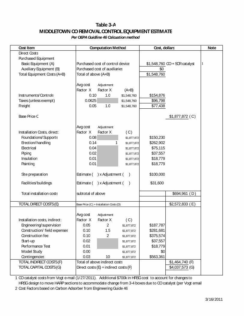
MIDDLETOWN CO REMOVAL CONTROL EQUIPMENT ESTIMATE
Cost Item Computation Method Cost, dollars NoteDirect CostsPurchased Equipment
Basic Equipment (A) Purchased cost of control device $1,548,760 CO + SCR catalyst 1
Auxiliary Equipment (B) Purchased cost of auxiliaries $0Total Equipment Costs (A+B) Total of above (A+B) $1,548,760
Avg cost Factor X
Adjustment
Factor X (A+B)Instruments/Controls 0.10 1.0 $1,548,760 $154,876Taxes (unless exempt) 0.0625 $1,548,760 $96,798Freight 0.05 1.0 $1,548,760 $77,438
Base Price C $1,877,872 ( C )
Installation Costs, direct:Avg cost Factor X
Adjustment
Factor X ( C )Foundations/Supports 0.08 $1,877,872 $150,230Erection/handling 0.14 1 $1,877,872 $262,902Electrical 0.04 $1,877,872 $75,115Piping 0.02 $1,877,872 $37,557Insulation 0.01 $1,877,872 $18,779Painting 0.01 $1,877,872 $18,779
Site preparation Estimate ( ) x Adjustment ( ) $100,000
Facilities/buildings Estimate ( ) x Adjustment ( ) $31,600
Total installation costs subtotal of above $694,961 ( D )
TOTAL DIRECT COSTS (E) Base Price (C ) + Installation Costs (D) $2,572,833 ( E )
Installation costs, indirect:Avg cost Factor X
Adjustment
Factor X ( C )Engineering/supervision 0.05 2 $1,877,872 $187,787Construction/ field expenses 0.10 1.5 $1,877,872 $281,681Construction fee 0.10 2 $1,877,872 $375,574Start-up 0.02 $1,877,872 $37,557Performance Test 0.01 $1,877,872 $18,779Model Study 0.00 $1,877,872 $0Contingencies 0.03 10 $1,877,872 $563,361
TOTAL INDIRECT COSTS (F) Total of above indirect costs $1,464,740 (F)TOTAL CAPITAL COSTS (G) Direct costs (E) + indirect costs (F) $4,037,573 (G)
1 CO catalyst costs from Vogt e-mail (1/27/2011). Additional $700k in HRSG cost to account for changes toHRSG design to move HARP sections to accommodate change from 3-4 boxes due to CO catalyst (per Vogt email
2 Cost Factors based on Carbon Adsorber from Engineering Guide 46
Table 3-A
Per OEPA Guidline 46 Calcuation method
3/16/2011

Cost Item Computation Method Cost, dollars NoteDirect operating costsOperating labor
Operator 39.15 $/hr 0 h/yr $0 (a) 1Supervision 15% of operator labor cost $0
Operating Materials As requiredCatalyst CO Catalyst $111,060 2Catalyst Additional SCR Catalyst $75,000 3Chemicals $0
Maintenance (general)Labor Estimated Maintenance Labor $19,200 (b)Materials 100% of Maintenance Labor Cost $19,200
Maintenance (Additional due to Ammonium Bisulfate Fouling on the Tubes)Labor Estimated Maintenance Labor $31,250 (c)Materials 100% of Maintenance Labor Cost $31,250
Replacement Parts As required $3,000Labor 100% of replacement part costs $3,000
UtilitiesElectricity (pressure loss) 0.068 $/kwh x 2,412,250 kwh/yr $164,033 4Electricity (Pwr Gen impact due to Higher Temp) 0.068 $/kwh x 365,818 kwh/yr $24,876 5Lost Power Gen due to Additional Downtime 0.068 $/kwh x 10,486,771 kwh/yr $713,100 6Steam
Waste disposal $/ton x Catalyst $0Wastewater treatment $/103 gal xTOTAL DIRECT OPERATING COSTS (A) subtotal of above $1,194,969 ( A )Indirect operating (fixed) costsOverhead 80% of O/M labor costs (a+b+c) $40,360Property tax 1% of capital costs $40,376Insurance 1% of capital costs $40,376Administration 2% of capital costs $80,751Capital recovery CRF .13388 (at 12%,20 yrs) x Capital $540,550TOTAL FIXED COSTS (B) Subtotal of Above $742,413 ( B )
No Product or Heat Recovery therefore credits = 0 $0 ( C )
TOTAL ANNUALIZED COSTS (A+B)minus ( C ) $1,937,382
CO Emissions from Unit 356 = tpy CO, Uncontrolled 7CO Removal - 90% Removal 320.4 = tpy CO, Removed
Cost Effectiveness $6,047 $/ton of CO removed12
3
4
567
Additional 1.2" wc DP (clean) due to CO Catalyst + another 2" wc for periodic clogging of catalyst
Performance Impact for increase in FW temp from 240 to 253°F
From Facility Emission tab
Table 3-BMIDDLETOWN CO REMOVAL CONTROL ANNUALIZED ESTIMATE
Per OEPA Guidline 46 Calcuation method
Assume no added labor for normal operationFrom Vogt email, catalyst replacement is $350,000 and labor cost is $20,200 for total of $370,200 every 3 years. Based on 6 changeouts over 20 years annual cost estimate.From Vogt on 20% more catalyst volume volume required due to ammonium bisulfate salts plugging and deactivating catalyst. Assuming same $/cuft cost (average of SCR bids for project).
2 days/year for planned inspections + 2 days/year of forced downtime due to high DP or other means. 1.1% on
3/16/2011
Attachment 2
Basis Documentation
"Parsons, Megan"<[email protected]>
02/03/2011 12:01 PM
To "[email protected]"<[email protected]>, "Lash,Frederick W."<[email protected]>
cc "Hensinger,Yvonne M." <[email protected]>,55607 <[email protected]>, 55807<[email protected]>
Subject CO Catalyst costs
Eric,Per our conversation –BMcD received firm HRSG bids for the project, including a breakout of SCR catalyst costs. Vogtindicated that the SCR would cost 20% more if CO catalyst is included (ref Vogt e-mail previously sent). 20% of the average of SCR catalyst bids received is equal to $200,000. Assuming replacement of SCRcatalyst every 3 yrs, this is an annual cost of $66,000….installed approx $75,000. To verify, Vogtindicated in a phone call that the increased SCR catalyst cost would amount to approx $75,000/yr. Vogtalso indicated that the increased depth of the catalyst (SCR and CO) would be 5 ft. deep…the vendordwgs received from the HRSG proposals indicate a 18-20’ wide HRSG. Therefore, we anticipate approxanother 5x20’ of catalyst for storage. The cost for the add’l building sqft is from the final APCI estimate,as prepared by BMcD. The building costs were from vendor quotations.
Megan Parsons, PEDevelopment Engineer, Energy DivisionBurns & McDonnellDirect: 816-823-7101Main: 816-333-9400Fax: 816-333-3690www.burnsmcd.com
"Parsons, Megan"<[email protected]>
01/27/2011 09:39 PM
To "Lash,Frederick W." <[email protected]>,"[email protected]"<[email protected]>,
cc "Leis, Darrell" <[email protected]>
bcc
Subject FW: FW: Air Products Middletown CO catalyst
See comments from Vogt below. Their anticipated costs have increased sincethey have looked at the actual design more closely. I'll work in the morningto re-summarize this to directly answer the questions, but wanted to get thisin front of you ASAP so you know where we're at...Vogt does not have catalyst volume for SCR or CO, I'm going to need to chasethis down with cat vendors tomorrow AM, and will try to get CO cat disposalcost or at least materials from them.
Megan Parsons, PEDevelopment Engineer, Energy DivisionBurns & McDonnellDirect: 816-823-7101Main: 816-333-9400Fax: 816-333-3690www.burnsmcd.com
-----Original Message-----From: [email protected] [mailto:[email protected]]Sent: Thursday, January 27, 2011 5:05 PMTo: Parsons, MeganSubject: Re: FW: Air Products Middletown CO catalyst
Megan,
Below is a summary of our conversation.
A) CO Catalyst and frame (initial cost): $648,7601) CO Catalyst cost: $550,000 for catalyst and frame. This is a
budgetary number.2) Additional 5 ft of ductwork: $40,000. This includes the cost
foradditional access doors, platforms, and ductwork.
3) Installation cost for CO catalyst frame (before steam blowsandfirst fire): 6 workers for 7 days (8 hour days) at a rate of $85/hour =$28,560
4) Scaffolding cost for installing CO catalyst frame: $10,0005) Installation cost for CO catalyst blocks (after steam blows):
5workers for 3 days (8 hour days) at a rate of $85/hour = $10,200
6) Scaffolding cost for installing CO catalyst frame: $10,000
B) Replacement CO Catalyst (after 3 year warranty): $370,2001) CO Catalyst cost: $350,000 for catalyst. This is a budgetary
number.2) Installation cost for CO catalyst blocks (after steam blows):
5workers for 3 days (8 hour days) at a rate of $85/hour = $10,200
3) Scaffolding cost for installing CO catalyst frame: $10,000
C) Additional SCR catalyst to accommodate CO catalyst: 20% increase in SCRcatalyst cost
1) The additional SO2->SO3 conversion added by the CO catalystwillincrease the salting temperature of the SCR. The margin between operatingtemperature and the salting temperature in some cases is only 5°F.The salting on the catalyst will mask the catalyst and lead todeactivation. Additional catalyst may help but we will need to knowexactly how much SO3 is entering the catalyst. Theestimatewas 15-20% additional catalyst volume which roughly equates to 15-20%increase in cost to provide the margin to over come the masking effect ofthe salts.
2) The preferred solution would be to move the CO and SCR into ahigher temperature zone of the HRSG to increase the operating marginbetween the salting temperature and the operatingtemperature.The effects of this are listed in the HRSG section
3) SCR catalyst warranty: 3 years. I assume that Burns &McDonnellcan account for these replacement costs.
D) Annual Inspections and cleaning: $45,000 - $80,0001) Annual inspection by VPI: $5,0002) Recommended Annual CO2 cleaning: $40,000. This is an average
cost. In some cases with heavy salt formation on the tubes, these costshave been up to $75,000.
E) HRSG design consideration: $700,0001) Additional gas side pressure drop for CO catalyst: 1.2 inwc2) Additional gas side pressure drop for extra SCR catalyst
required: 0.2 inwc3) Expected gas side pressure drop to develop annually: 1-2
inwc.This assumes that the finning on the modules in the last box would becomeplugged.
4) SCR catalyst would need to be moved into higher temperatureregion. Currently, it's behind HP evaporator 1. We would have to splitthe HP evaporator 1 surface into 2 modules harps. This isbecausethe temperatures in front of HP Evaporator 1 could reach 850°F. This wouldcreate SS frames for the CO and SCR catalyst. These costs would beexcessive. Therefore, a more practical solution would beto splitthe HP Evaporator 1 into 2 modules. The two-wide three-box deep designwould become 4 boxes deep. Burns & McDonnell can account for the increasederection costs associated with the addition of twoboxes.
5) The $700,000 is combination of Alternate No.8 option (withrespect to the base design) and adding two module harps and associatedpiping.
Please let me know if you have additional questions.
Kind regards,
Jeremy A. WilliamsAccount Manager
Vogt Power Internationaloffice: +1 (502) 899-4579cell: +1 (502) 418-9494email: [email protected]
"Parsons, Megan" <mparsons@burnsmc d.com> To "[email protected]" 01/26/2011 02:31 <[email protected]> PM cc Subject FW: Air Products Middletown CO catalyst ***************************************************************************