marc caumont, sylvie ponthieu to cite this version
TRANSCRIPT
HAL Id: ineris-00972199https://hal-ineris.archives-ouvertes.fr/ineris-00972199
Submitted on 3 Apr 2014
HAL is a multi-disciplinary open accessarchive for the deposit and dissemination of sci-entific research documents, whether they are pub-lished or not. The documents may come fromteaching and research institutions in France orabroad, or from public or private research centers.
L’archive ouverte pluridisciplinaire HAL, estdestinée au dépôt et à la diffusion de documentsscientifiques de niveau recherche, publiés ou non,émanant des établissements d’enseignement et derecherche français ou étrangers, des laboratoirespublics ou privés.
Safety provisions and LPGMarc Caumont, Sylvie Ponthieu
To cite this version:Marc Caumont, Sylvie Ponthieu. Safety provisions and LPG. 15. Hazards Symposium ”The Processits Safety and the Environment”, Apr 2000, Manchester, United Kingdom. �ineris-00972199�
2000-32 V'B
SAFETY PROVISIONS AND LPG
Marc CAUMONT and Sylvie PONTHIEUInstitut National de l'Environnement Industriel et des Risques,Parc Technologique ALATA , BP 2, 60550 Verneuil-en-Halatte, France
The safety of an industrial site depends in particular on the characteristics of thesafety devices employed and the equipment installed.In France, the safety evaluation of an installation is carried out, in particular, throughhazard analysis. However, the absence of objective criteria for safety deviceevaluation makes the task difficult . Different pieces of equipment that assure the,same function don't necessarily have the same safety level.Consequently, INERIS undertook a study including:- an outline of the various practices based on an inventory of French regulation and acomparison with regulations applied in other European countries,- an accidentology allowing one to focus on some important safety devices,- a description of the various devices that can be encountered on a L.P.G site,accompanied by a collection of descriptive boards of safety devices used withL.P.G.,- a presentation of the concept of devices that are " Important For Safety ", withdefinitions of commonly-used terms,- a presentation of some approaches for taking into account safety devices in theevaluation of the risks or specific methods used for the evaluation of a L.P.G. site.
Keywords : L.P.G., safety device
INTRODUCTIONIn 1997 there were 95 establishments in France storing at least 300 cubic metres (m3) of LPG(exclusively butane and propane) not including the underground storage sites.Some 90% of these 95 sites were created between 1956 and 1975.These sites have over 300,000 m3 of storage capacity made up as follows :
• Mounded tanks : 23,600 m3 (10 sites),• Above ground spherical tanks : 220,000 m3 (68 sites),• Cylindrical tanks : 27,000 m3 (49 sites),• Cryogenic tanks : 60,000 m3 (3 tanks on a single site).
Four operators account for 54 of these sites ; chemical firms and refineries operate 15 of them.The remaining 26 sites are where LPG is used as a utility for heating plants, industrialfurnaces, and so on, for a variety of activities.There are at least about 182 spheres (100 containing butane and 82 propane), 200 horizontaltanks and 2 vertical cryogenic tanks (35,000 and 20,000 m3). The capacity of the spheresvaries from 300 to 5.000 m3. Mounded tanks include horizontal tanks some of which havesubstantial capacity (3,000 m3) and spheres (from 1,000 to 3,500 m3). In France there are also23 industrial sites (essentially in the chemical industry) storing products similar to LPG (forexample, butadiene) with tank capacities ranging from 80 to 9,000 m3.
In the current situation of technological change INERIS is undertaking a study for the FrenchMinistry of Environment (MATE) in the following five areas :
• A description of the different types of industrial facilities in France using LPG,specifying the different industrial practices involved,
• An inventory of the principal current regulatory requirements in different Europeancountries (notably the UK, the Netherlands, Belgium and Italy) and a comparison withFrench requirements,
• The feedback of experience based upon an analysis of industrial accidents involvingLPG,
• Identifying systems which are important to safety,• An evaluation of the consequences of various accident scenarios according to the safety
systems present on the installation.
This study is still in progress. Hereafter some extracts of the sections covering an overview ofFrench LPG sites, the comparison of regulations and the feedback of experience are brieflypresented.
OVERVIEW OF FRENCH INDUSTRIAL SITES UTILISING LPGThe French sites utilising LPG can be subdivided into 7 main categories :
• Refineries (producing and storing LPG and distributing it to "buffer" and/or operatingsites) ;
• "Buffer" sites (receiving and storing LPG and distributing it to operating sites) ;• Operating sites (receiving and storing LPG and distributing to clients and to "local
depots") consisting of :•> fillin g centres (distributing LPG in bulk, "packaging" and distributing cylinders) ;• intermediate depots (distributing only bulk LPG) ;
• So-called "local depots" (receiving and storing LPG and distributing it in bulk toclients), which are similar to the intermediate depots but store smaller quantities(storage capacity < 120 m3).
• Industrial sites employing LPG as a utility for an industrial process (for example,heating plants, industrial furnaces, and so on).
• Chemical sites employing LPG as a raw material.• The cosmetic industry employing LPG as a propellant gas (aerosols).

In the following we shall disregard industrial sites employing LPG as a raw material, utility orpropellant gas. Some characteristics of the different types of French industrial site whereactivities are entirely or partly focused on LPG are given in the following table :
Type ofsite
Refinery
"Buffer"site
Fillin gcentre
Intermediatedepot
Localdepot
Type oflocation
Largeindustrialcomplex
Largeindustrialcomplex
Industrialzone orsuburbanzone
Industrialzone orsuburbanzoneSuburbanzone
Type of tank
Spheres (> 10)horizontaltanks (>10)
SpheresRefrigeratedtanksUndergroundcavitiesSpheres (< 10)Horizontaltanks (< 10)
Spheres (1 or2)Horizontaltanks (<4)1 horizontaltank (volume< 120 m3)
LPG entry
(Internal)
PipeShip
PipeWagonsTrucks
WagonsTrucks
Trucks
LPGdespatch
PipeShipsWagonsTrucks
WagonsTrucks
Trucks
Trucks
Trucks
Remarks
Despatchesfrequentlymade byindependentsitesEntry bytruck veryrare.
ForpackagedLPG, thecylindersaredespatchedby truck.
Siteworkforc
e>100(firemenon thesite)
>20
About 20
Of theorder of 2
Overview of French LPG sites
This table illustrates the general trends for the various industrial configurations that exist. Ofcourse, there are exceptions, notably concerning the number and type of storage tanks.
TANK EQUIPMENTFor the tanks themselves, French regulations require to mound them (for capacity greater then500 mJ). This makes it possible to reduce safety distances for major accident scenarios. Quitea number of the existing spheres have been "mounded" by being covered with "TEXSOL"(special blend of sand and synthetic fibres). Use of this technique has allowed continued useof sites that were threatened by housing developments. More than a dozen industrial .siteshave used this technique for protecting their spheres.

Apart from the safety fundamentals - proper pressure vessel design, provision for hydraulicand seismic loading, and so on - the strategies applied with respect to tank auxiliaries havethe following objectives :
• to limit any spread of product,• to protect the tanks against any thermal effects,• to a lesser degree, to protect the tanks from impact missiles.
The safe state for tanks is attained by remote controlled safety valves on each connections thatclose automatically if gas or a flame is detected on site. In addition, the liquid outletconnections are fitted with internal remote controlled safety valves (usually hydraulicallyoperated). Bunds are the rule around above ground tanks.Thermal and mechanical protection is attained by adding one metre of earth or an equivalentthickness of TEXSOL (60 centimetres). For above ground tanks, protection against thermaleffects is provided by a spray system (10 Iitres/m2.min).Regarding the protection against missile impact, mounded tanks (under earth or TEXSOL).are inherently safe. Above ground tanks - most French LPG tanks are of this type - do notmeet this safety objective apart from a few rare exceptions (when tanks are protected by aconcrete wall or dome)
INVENTORY AND COMPARISON OF LPG REGULATIONS
GENERALThe different regulations or '"reference documents" specific to LPG facilities weresummarised for five countries : the Netherlands, the United Kingdom, Italy, Belgium andFrance.Of the five countries considered, only Belgium(1), Italy(2) and France( j ) have specificregulations for LPG facilities. The respective sources are given in chapter referneces.In the Netherlands, the directive "LPG distribution depots"(4) serves as the basis for definingthe regulatory requirements governing the issue and renewal of licences for operating suchinstallations.In the United Kingdom, two reference documents*5* may be used, one from the Health &Safety Executive, and the other from the British Institute of Petroleum. However these twodocuments provide guidance and do not have the force of law.It may be noted that general or particular legislation not specific to LPG facilities may containrequirements that also apply to such facilities. Such legislation is disregarded in this study.Our inventory was drawn up using, first, the above documents and, secondly, informationobtained from industry and government representatives in the countries concerned.Notwithstanding this, the inventory should not be regarded as exhaustive.Apart from the classification of products, the main items dealt with in these regulations are :
• Rules for the location of tanks<• Distances from establishment boundaries• Distances between tanks
• Protection of water• Fire lighting measures• Gas detection• Control valves• Relief valves• Level measurements• Pressure measurements• Temperature measurements

As an example, the following table summarises the situation as to the regulatory requirementsfor safety valves on liquid outlets from tanks.
France
Netherlands(recommended)
United Kingdom(recommended)
Belgium
Italy
l sl valveMotorised,inside the tankManual,as close to tank aspossible,1st flange weldedMotorised,or excess flowvalve,or non-return valveMotorisednon-return valveLiquid outlet :manualLiquid outlet:manual
2nu valveMotorised
Motorised,as close as possibleto 1 st valve
Motorised,if 1st valve manual
Excess flow valveNon-return valve
CommentsFail safe
Fail safe
Fire safe
Fail safe
Fire safeValves designedforP > 40 bar
Summary of regulatory requirements for valves on liquid outlets
This comparison reveals appreciable differences in approach between the different countriesconsidered. In France for example, internal valves are required on liquid outlets while theother countries considered have opted for safety devices outside the tank.
LPG ACCIDENTSAccidents are unfortunately a prime consideration from the safety standpoint, whether interms of prevention, protection or control. The accident analysis performed is based mainly oninformation available in the "ARIA " database(6). It was done for each zone of activity - forexample storage, transfer (loading/unloading), cylinder filling , etc., and also for each type ofphenomenon : BLEVE (Boiling Liquid Expanding Vapour Explosion), explosion and fire.The following summary refers only to the analysis of accidents occurring during LPG transferoperations involving tanker trucks or w7agons.

REVIEW OF ACCIDENTS OCCURRING DURING LPG LOADING OR UNLOADING
Statistical analysisThe statistical analysis of LPG accidents occurring during loading or unloading covers asample of 33 events, most of the data being taken from the ARIA database. These events tookplace in the period 1951 to 1998. Although the sample is on the small side, we shall try todeduce the main trends. A breakdown of where the accidents took place is shown below.
Fillingcenter or
depot31% .-—-
TÏIIIIndustrialclients
13%
Others16%
Privatepremises
^ 40%
Distribution of accidents by type of location
It wil l be seen that the processes of unloading LPG on private premises and industrial sites (inbulk) alone account for over half (53%) of the events listed. In both these circumstances,transfer is practically always done using equipment carried on the tanker trucks (pumps, hoseson reels; etc.). It should be borne in mind that a truck serving private clients (capacity limitedto 6 or 9 tonnes) fills up at the fillin g centre or depot and then delivers supplies to an averageof 10 clients. The number of unloading operations by these trucks at private premises farexceeds the number of their loading operations at LPG centres.Ten accident events are listed in connection with operations at these LPG centres. The twoearliest events (Port Newmark in 1951 and Brinkley in 1957) shown in the "others" categorycould probably be included with them.No particular analysis of the geographical location of the accidents was done since thosereported by the different sources are strongly influenced by the availability of information. Infact the proportion of the accidents taking place in Europe and North America is very highcompared with other parts of the world. Here it is interesting to note that countries, likeRussia, apparently had very few accidents. As a result the list is not exhaustive since anumber of accidents probably took place with no report being published either by the mediaor the international organisations.As to the time distribution of the events, the number of cases reported appears to rise steadilyas time passes : 50% of the accidents have been in the last 10 years. This observation isprobably related to the growth of safety policies and the enhanced media attention foraccidents and incidents that impose a wider circulation of information.

Phenomena observedThese have been classified into five categories :
Phenomenon1. Liquid spreading on the ground2. Gas phase leak without ignition
Jet (or pool) fire4. Gas or vapour explosion5. BLEVEofatank
Phenomena used as a basis for classifying accidents
It is worth noting that phenomena 1 and 2 can be precursors of 3 or 4, while the flare (or pool)fire can be the precursor of 5 (a BLEVE). In other words, a leak of flammable product(whether liquefied or not) may ignite well after it spreads. The following figure shows thedifferent phenomena involved. The phenomenon shown in the following classification is themost significant one noted during the accident (for a leak followed by a fire, this type ofaccident is placed in the fire category).
Gas leakSpreading liquid
0%without ignition
20%
Jet or pool fire20%
Explosion24%
BLEVE36%
Distribution of events by observed phenomena
Thus it can be seen that the main phenomenon characterising accidents during LPG transferoperations is a leak followed by ignition of the cloud formed, which in most cases (60%)leads to the effect of overpressure (24%) or a fireball (BLEVE : 36%). However ignitiondidn't occurred in 20% of the cases reported.The two phenomena of fire and explosion (including BLEVE). which of course regularlyoccur together, account for more than two thirds of the accidents (80%).I-or the cases listed it wil l be seen that a leak is usually accompanied by the formation of acloud that drifts with the prevailing wind. The ignition of this cloud at a distance (possibly ata considerable distance) is followed by a "flame return" that can cause fire under the road orrail tanker or tankers or its immediate vicinity.

The known BLEVEs listed in the literature result, in all the cases listed above, from a fireheating the tank, leading to an increase in pressure and mechanical failure. This phenomenontherefore affects ordinary above ground tanks, i.e., those where the shell has littl e or noprotection from thermal effects. Among the accidents listed, inadequate means of protectionare regularly identified as decisive in the development of an accident sequence towards aBLEVE.Explosions of flammable gases are the result of a gas leak followed by ignition of the cloud ifthis is wholly or partly enclosed in a confined space. A large number of experiments haveshown that the ignition of a gas cloud in free space, in the case of LPG, does not generatesignificant overpressure that is harmful to the environment. This is confirmed by accidentreports. Indeed this condition of partial containment is probably the reason why mostexplosions of combustible gas (with the appearance of overpressure effects) concernproduction units, where there is usually a high density of equipment (with seals, valves, etc.)in a small volume, or leaks on customer's premises, for example when the cloud has entered adwelling. Of course in these cases the explosion of the cloud could cause damage and leaks tothe other tanks or mobile tankers (the domino effect).Finally we may note that only one of the listed events mentions an incident that did not giverise to a leak and that no report mentions the presence of LPG in the liquid phase on the" round.
The severity of accidentsThis was evaluated simply by dividing the accidents into two categories :
• Accidents not resulting in casualties.• Accidents resulting in casualties.
Some 55% of the accidents did not result in casualties. In 15 of the listed cases there werecasualties (injury or death) and the phenomena responsible are shown in the figure below.
BLEVEOthers 13%33%
Fire34%
Causes of injury or death
Fire (excluding fireballs) is the main cause of casualties with 5 accidents. The victims werepeople present in the gas cloud when it ignited. The "other"" category (5 cases) mainlycontains accidents for which there is no information as to the cause of casualties (4 cases) and.in the 5th case, the operator had a fall following a leakage of LPG.These 1 5 accidents were responsible for a total of 236 victims with 26 deaths and 210 injured.It is worth pointing out that two events resulting in a BLEVE alone accounted for 14 deathsand 144 injured.
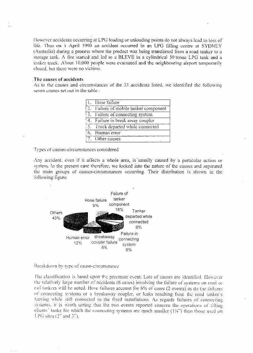
However accidents occurring at LPG loading or unloading points do not always lead to loss oflife. Thus on 1 April 1990 an accident occurred in an LPG fillin g centre at SYDNEY(Australia) during a process where the product was being transferred from a road tanker to astorage tank. A fire started and led to a BLEVE in a cylindrical 50 tonne LPG tank and atanker truck. About 10,000 people were evacuated and the neighbouring airport temporarilyclosed, but there were no victims.
The causes of accidentsAs to the causes and circumstances of the 33 accidents listed, we identified the followingseven causes set out in the table :
1.2.
4.5.6.7.
Hose failureFailure of mobile tanker componentFailure of connectingFailure in break awayTruck departed whileHuman errorOther causes
systemcouplerconnected
Types of causes-circumstances considered
Any accident, even if it affects a whole area, is "usually caused by a particular action orsystem. In the present case therefore, we looked into the nature of the causes and separatedthe main groups of causes-circumstances occurring. Their distribution is shown in thefollowing figure.
Others43%
Hose failure9%
Human error Breakaway12% coupler failure
6%
Failure oftanker
component1 8 % Tanker
departed whileconnected
6%
Failure inconnecting
system6%
Breakdown by type of cause-circumstance
The classification is based upon the precursor event. Lots of causes are identified. Howeverthe relatively large number of accidents (6 cases) involving the failure of systems on road orrail tankers wil l be noted. Hose failures account for 6% of cases (2 events) as do the failuresof connecting systems or a breakaway coupler, or leaks resulting from the road tanker'sleaving while still connected to the fixed installations. As regards failures of connectingsystems, it is worth noting that the two events reported concern the operations of fillingclients' tanks for which the connecting systems are much smaller (VA") than those used onLPG sites (2" and 3").
Human error, which could also have been identified as a major cause in the case of tankersdeparting when still connected, covers two types of error in this classification :
• Opening the wrong line, allowing product to discharge to atmosphere (2 accidents inGermany).
• Operator error leading to the bursting of a hose, for example the accident at Divonnes-les-Bains or the discharge of product when liquid was being taken from a client's tank(the accident at Mouans-Sartoux).
Feedback of experienceIn view of the small number of accidents listed, and taking into consideration the variety ofpossible scenarios, we must point out that the preventive, protective or control measuresreferred to in this paragraph are not the only ones taken at loading or unloading facilities onFrench LPG sites.The accidents listed are usually characterised :
• by a leak either from the road or rail tanker or from the fixed installation,• by the ignition of the cloud, often outside the site,• by the means of control, notably spray systems, frequently inoperative either through
their design or as a result of damage when the accident sequence began.
From these facts it is clear that the objectives as regards measures of prevention, protectionand control should be :
• to employ high quality and reliable systems,• to minimise any accidental releases of product,• to cool tanks to prevent their bursting in the event of ignition.
The measures described below are guided by these objectives.
For the fixed installationHoses
A few accidents have occurred on site during the transfer of liquefied gases. A good numberof these involved hoses, a technique no longer employed on French LPG sites except for oneor two where they are used for the gas phase. For both loading and unloading operations onLPG sites, articulated metal arms are the rule both for road and rail tankers.Each transfer arm is usually fitted with two automatic isolating devices and the transfer zonesare under continuous surveillance for gas leaks or heat sources. These aspects are describedbelow.It wil l be noted that hoses are still used for the operations of loading and unloading liquefiedtoxic gases such as ammonia, chlorine, and so on.
One-wax valvesThese are useful only when tanker trucks or wagons are being unloaded. In thesecircumstances the one-way valve can substantially limi t the quantities of product dischargedto the atmosphere from the fixed installations. This passive system has the advantage of ashort response time but serves no purpose in the case of fire or increased temperature. To beeffective, it should be fitted as close as possible to the base of the arm. just before or after themotorisée! valve at that point.

Brcakaw'ay couplerThe causes of accidents include the unexpected movement of the road or rail tanker duringloading or unloading. Whatever the cause of the movement of the tanker whose product isbeing transferred, the presence of breakaway coupler ensures that the mechanically weakpoint of the system consisting of the road or rail tanker, its pipework, the articulated arm andthe fixed installation, lies between two automatic isolating valves.The breakaway coupler should have the following two characteristics :
• It should create a weak point in the transfer arm that wil l fail under abnormal stress.• An automatically closing isolating valve is positioned at both sides of this weak point.
This arrangement can limi t the amount of LPG discharged to the atmosphere, if the valve isopen, to a few hundred grammes.It wil l be noted that two accidents arising from malfunctions of such breakaway coupler arelisted in this study. They occured before the system has been modified.
Gas and fire detectorsProduct transfer systems should be located in areas where there is continuous detection of :
• gas
- flame• heat
It is of course extremely difficul t to determine the best detection positions particularly forflames and gas.
Gas detectionGases are usually detected using sensors with two alarm concentration levels : 20% and 50%of the Lower Flammable Limi t for the gases, and which generally lead to :
• 20% LFL : audible and visible alarm,• 50% LFL : audible and visible alarm, with the site setup in safe condition by closing the
motorised safety valves at the base of the arms and all motorised safety valves of alltypes on the site, and possibly automatic spraying of the installations.
Flame detectionThis can involve flame detectors (of the infrared or other type). Detection of flames by asensor should, besides raising an alarm, at least put the site in a safe condition and possiblyinitiate automatic spraying of the installations.
Detection of heatDue consideration should be given to the potential ignition of a flammable gas cloud, asindicated by the accidents listed in this study. To limi t the consequences of such an event eachmotorised valve at the base of the arm (and indeed all the motorised valves on the site) shouldbe placed in a safe position automatically in the event of any rise in temperature in theirimmediate vicinity. If the valves are operated pneumatically, this objective can be achieved byintroducing a compressed air supply pipe which, over the last few metres before the actuator,is made of a meltable material. Then any substantial rise in temperature (about 80°C) in thevicinity of the valve wil l melt its supply pipe and lead to the automatic closure of themotorised valve.

For mobile tankersRailway tankers
Rail tankers have two nozzles at the bottom of the tank, one for the liquid phase and one forthe gas phase (fitted with an extension tube opening into the gas phase). Each nozzle has :
• a stop valve, inside the tanker, which can only be opened and kept open by pulling onthe operating lever ; this is done by introducing a hook secured to the valve operatinglever (or to the extension cable) and to the rail track, in order to maintain a continuouspull on the valve operating lever ;
• a manual valve.
Removal of the hook, for any reason, leads to the automatic closure of the stop valve underthe effect of the closure springs it contains.Three types of hook may be encountered :
• mechanical,• pneumatic.• electromagnetic.
The hooks, whether of mechanical or other design, are automatically released if the rail tankershould be accidentally moved, causing the automatic closure of the valves at the bottom of therail tanker. However the motorised hooks (pneumatic or electromagnetic) have the advantagethat they can be operated by gas or fire detectors and by pressing an emergency stop button,which means that the placing of the rail tankers being loaded or unloaded in a safe conditioncan be incorporated in the general process of placing the site in a safe condition.Mechanical hooks on the other hand, if a leak should occur without wagon movement, canonly be operated by a cable some 30 metres in length (usually) and on condition that the cableis not in the gas cloud.Finally, we should mention an original technique-which, instead of fixing up the hook on therail, employs a pneumatic hook-retaining bar, a technique that has been systematically appliedto sites. The system consists of a bar parallel to the rail and near to it, held in this position bybeing clamped axially by a pneumatic jack. The hook is then secured to this bar rather than tothe rail.Any detection of gas, flames or heat (by the meltable pipe supplying compressed air to thejack that retains the bar) or actuation of one of the emergency stop buttons on the site, releasesthe hook retaining bar, thus causing the automatic and instantaneous closure of the valve orvalves at the bottom of the rail tanker or wagons.
Where the hooks are motorised or attached to a bar retained in position pneumatically, it is nolonger necessary to use a chain or cable to remotely operate the hook.Some of the advantages of motorised hooks are the following :
• They have been proven on a number of sites.• These systems are integrated into the site safety scheme, since they operate
automatically if gas or flame is detected or an emergency stop actuated.• They are fail safe devices, since in the event of an anomaly they take up a safe position.• These devices are easilv tested.
Tanker truckslivery nozzle (liquid or gas) on road tankers (small and large bulk carriers) is fitted with aninternal safety valve usually operated hydraulically. These valves close automatically in caseof tire thanks to the presence of a fuse plug. However the closure of these safety devicescannot be integrated into the automatic site safety scheme. This aspect deserves closeattention.
( 'oo/ing systems on mobile tankersFaulty operation or weaknesses of cooling systems in installation are often blamed whenscenarios develop catastrophically (into a BLEVE). LPG loading and unloading units are notusually fitted with fixed spray systems. Only those sites where fixed tanks have beenmounded are usually fitted with such systems, the embankment of fixed tanks (on existingsites) releasing substantial amounts of firefighting water. Both rail and road tankers are veryfrequently fitted with a sunscreen. Small tanker trucks (that fill up at LPG sites) are providedwith a rear locker containing the different components to be protected. Rail tankers are fittedwith skirts at the bottom where the tanker is secured to the chassis. The effectiveness of fixedspray systems could therefore be significantly and adversely affected by these arrangements.Accordingly spray systems should combine fixed installations (headers) and judiciouslylocated fire hydrants so as to be able to spray all the road or rail tankers involved as well aslocal areas not cooled by the fixed installations.In order to help the cooling of rail tankers, it is preferable not to place two trains side by sidebecause in that case effective spraying of the arms (between the two trains) and the wagonnozzles is extremely difficul t if not practically impossible.The time taken to start up fixed systems (fixed headers) should be as short as possible.Automatic spraying, initiated by the gas or flame detection systems (at the very least) wouldprobably ensure effectiveness.
LESSONSExcept in the two cases of accidents concerning failure of the breakaway coupler, one cannote that the installations blamed in the accident reports were not usually fitted with the safetysystems described above.In concluding this chapter on the feedback of experience concerning LPG loading andunloading operations, it may be noted that in the absence of satisfactory safety arrangementson these installations, two main phenomena may occur :
• explosion or ignition of a gas cloud following the accidental release of LPG to theatmosphere ,
• a BLEVE in a mobile tanker.
CONCLUSION
This study is intended to provide the French Ministry of Environment with a reference baseregarding regulatory trends in a few neighbouring countries concerning the best industrialpractice. It may also provide guidance for developing French regulations for LPG.

References(1 ) - Belgium"Arrêté royal concernant les dépôts, en réservoirs fixes non réfrigérés, de gaz propane et degaz butane liquéfiés commerciaux ou leurs mélanges" - 21 October 1968
(2) - ItalyApprovazione délia regola teenica di prevenzione incendi per la progettazione, la costruzione.Tinstallazione e Tesercizio dei depositi di G.P.L. in serbatoi fissi dicapacità complessivasuperiore a 5 mJ e/o in recipienti mobili di capacité complessiva superiore a 5.000 kg"Ministerial Decree of 13 October 1994 (Ministry of the Interior) -
(3) - France• " Arrêté du 9 novembre 1972, règles d'aménagement et d'exploitation des dépôts
d'hydrocarbures liquéfiés" - - Ministère de l'industrie• "Arrêté du 09 novembre 1989, relatif aux conditions d'éloignement auxquelles est
subordonnée la délivrance de l'autorisation des nouveaux réservoirs de gaz combustiblesliquéfiés" - Ministère de l'Aménagement du Territoire et de l'Environnement
• "Arrêté ministériel du 10 mai 1993 (Ministère de l'Aménagement du Territoire et derEnvironnement), relatif au stockage de gaz inflammables liquéfiés sous pression" -Ministère de l'Aménagement du Territoire et de l'Environnement
(4) - The Netherlands"LPG distribution depots (Butane, propane, and their mixtures thereof)" Directive issued bythe Committee on the Prevention of Disasters due to Hazardous Materials (CPR) - 1994
(5) - United Kingdom• "The storage of LPG at fixed installations, brochure SHG 34 (1987)" - Health & Safety
Executive — UK• "'Liquefied Petroleum Gas - part 9 (February 1987)" - British Institute of Petroleum - UK
(6) - ARIAdatabase of the French Ministry of Environment - Direction de la Prévention des Pollutions etdes Risques - Service de l'Environnement Industriel - Bureau d'Analyse des Risques etPollutions Industrielles