mapdccd - cluster driver wiring diagram · web viewdccd dash light cluster driver - general...
TRANSCRIPT
DCCD DASH LIGHT CLUSTER DRIVER - GENERAL INFORMATION
Cluster drivers for Generation 2 MapDCCD controllers show: Real time DCCD lock Operation mode Fault codes
Cluster drivers for Generation 1 MapDCCD controllers show: Real time DCCD lock
The MapDCCD Cluster Driver modules are specific to either Generation 1 or 2 MapDCCD controllers.
By default, we ship modules for Generation 2 MapDCCD controllers.
Tell us if you require a module for your Generation 1 MapDCCD controller.

DASH CLUSTER DRIVER
Supplied with loomfor Gen 2 controller
DASH CLUSTER
LOCKED
▼
▼
▼
▼
Digital (White)
Power (Red)
Ground (Black)
AUTO Mode Lamp (Optional)
UNLOCKED
▼
AUTO
LOCK
▼
▼
▼
Analog
CLUSTER DRIVERS FOR GENERATION 2 MAPDCCD CONTROLLERS
* Requires MapDCCD Firmware Version 2.8 or higher** Consult your Subaru wiring diagram for cluster lamp connections
MapDCCDCONTROLLER
Gen 2

DASH CLUSTER DRIVER
Supplied with loomfor Gen 1 controller
DASH CLUSTER
LOCKED
▼
▼
▼
▼
Digital
Power (Red)
Ground (Black)
AUTO Mode Lamp (Optional)
UNLOCKED
▼
AUTO
LOCK
▼
▼
▼
Analog (White)
Connect to the same Signal Ground that MapDCCD is using
Connect to the same 12v ignition switched power that MapDCCD is using
CLUSTER DRIVERS FOR GENERATION 1 MAPDCCD CONTROLLERS
* Consult your Subaru wiring diagram for cluster lamp connections
The cluster driver power and ground connections must be spliced into nearby power and signal ground.
The Cluster Driver analogue input (thin white wire) connects to the MapDCCD Data-logging Output (thin white wire)
MapDCCDCONTROLLER
Gen 1
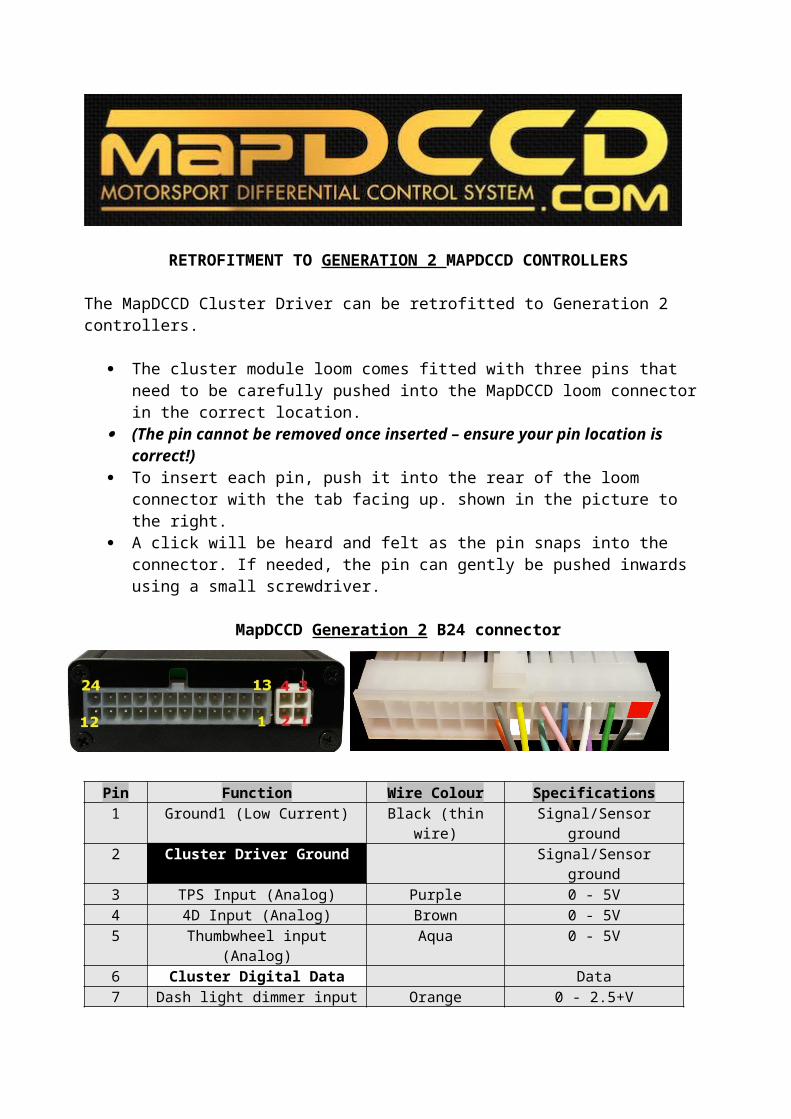
RETROFITMENT TO GENERATION 2 MAPDCCD CONTROLLERS
The MapDCCD Cluster Driver can be retrofitted to Generation 2 controllers.
The cluster module loom comes fitted with three pins that need to be carefully pushed into the MapDCCD loom connector in the correct location.
(The pin cannot be removed once inserted – ensure your pin location is correct!) To insert each pin, push it into the rear of the loom connector with the tab facing up.
shown in the picture to the right. A click will be heard and felt as the pin snaps into the connector. If needed, the pin can
gently be pushed inwards using a small screwdriver.
MapDCCD Generation 2 B24 connector
Pin Function Wire Colour Specifications1 Ground1 (Low Current) Black (thin wire) Signal/Sensor ground2 Cluster Driver Ground Signal/Sensor ground3 TPS Input (Analog) Purple 0 - 5V4 4D Input (Analog) Brown 0 - 5V5 Thumbwheel input (Analog) Aqua 0 - 5V6 Cluster Digital Data Data7 Dash light dimmer input Orange 0 - 2.5+V89
10111213 Cluster Driver Power 12V battery power14 RPM input (Pulses) Green 0 - 2.5+V15 Data logging output (Analog) White (thin wire) 0 - 5V16 Speed Sensor Input (Pulses) Blue 0 - 2.5+V17 Brake Input (Digital) Pink 0 - 2.5+V18 Handbrake Input (Digital) Yellow 0 - 2.5+V19 ABS Input (Digital) Grey 0 - 2.5+V
20-24