manuscript ajs & jmr ss en aspect ratio ii paper 210311 1st rev v2 full text.pdf
TRANSCRIPT
Published in: Journal of Constructional Steel Research, 67(10), 1545-1553.
DOI: http://dx.doi.org/10.1016/j.jcsr.2011.03.027
1
Steel silos with different aspect ratios:
II – behaviour under eccentric discharge
A.J. Sadowski & J.M. Rotter
Abstract
The phenomenon of eccentric discharge is widely recognised as the most dangerous
condition for thin-walled metal silos and the cause of many catastrophic buckling
failures. A realistic pressure model for this condition appears in a regulating standard
for the first time in EN 1991-4 (2006) on Actions on Silos and Tanks. However the
structural consequences of its application are currently largely unknown. The
behaviour of a silo subjected to these pressures is certainly very dependent on the
aspect ratio of the silo, the granular solid properties and the discharge channel
geometry.
This paper explores the behaviour of four thin-walled cylindrical silos with stepwise-
varying wall thickness and aspect ratios varying from intermediate to very slender,
subject to the codified EN 1991-4 eccentric discharge pressures. It is shown that a silo
design that was found to be very safe under the EN 1991-4 concentric discharge
pressures becomes very unsafe under eccentric discharge. Further, as it is known that
the aspect ratio has an important effect on the flow pattern in discharging granular
solids, and that slender silos exhibit very different flow patterns from squat silos, it is
currently not certain whether a suitable range of aspect ratio over which the codified
eccentric discharge model is to be applied has been prescribed in the standard.
This paper is the second of a pair. In the first, the behaviour of a set of example silos
under the EN 1991-4 concentric discharge condition was studied. The same example
silos are studied here under eccentric discharge.
Keywords: eccentric discharge; silos, aspect ratio; shell buckling; finite element
analysis; shells under unsymmetrical pressures.

Published in: Journal of Constructional Steel Research, 67(10), 1545-1553.
DOI: http://dx.doi.org/10.1016/j.jcsr.2011.03.027
2
1. Introduction
The phenomenon of eccentric discharge is widely understood to be the most serious
loading condition for a thin-walled metal silo, and the cause of many catastrophic
buckling failures in the past. The associated patterns of normal pressures and
frictional tractions exerted by the eccentrically flowing granular solid are known to
produce very unsymmetrical patterns of stresses in the silo wall, which precipitate
early buckling failure (Rotter, 1986; 2001a; 2001b; Sadowski & Rotter, 2010; 2011).
With recent advances in the power of both computers and the finite element method,
it is now possible to undertake nonlinear analyses of thin metal silos under complex
load patterns that were extremely difficult only a decade ago.
Key:
1) Internal (taper) pipe flow
2) Mixed flow
3) Eccentric taper pipe flow
4) Eccentric parallel pipe flow
Stationary Stationary
Flow channel
boundary
Retaining
silo
1
Squat
silo
Stationary Stationary
Flow channel
boundary 1
Slender
silo
Stationary Stationary
Flowing
Flow channel
boundary
Effective
hopper
Effective
transition
2
Very slender
silo
Stationary
Flowing
Flow channel
boundary
Effective
transition
3
EN 1991-4
eccentric discharge
flow model
Stationary
Flowing 4
Fig. 1 – Aspect ratio effects in different flow patterns, after EN 1991-4 (2006)
In the companion paper, it was stated that the classification of silos in the European
standard EN 1991-4 (2006) on Actions on Silos and Tanks is made on the basis of
their aspect ratio (height to diameter, H/D), which greatly influences the distribution
of axisymmetric pressures in the silo under mass flow. The aspect ratio is also known
to have an important influence on the possible patterns of mixed and pipe flow (Fig.
1), with squat silos having significantly different pipe flow regimes from slender ones
(Hampe, 1987; Rotter, 2001a; EN 1991-4, 2006). The flow pattern in turn influences
the pressures exerted by both the static and flowing solid components on the silo wall,

Published in: Journal of Constructional Steel Research, 67(10), 1545-1553.
DOI: http://dx.doi.org/10.1016/j.jcsr.2011.03.027
3
and thus the structural behaviour of the silo. The numerous studies that tried to predict
the pressures in the silo numerically based on an assumption of a particular flow
pattern (e.g. Holst et al., 1999a; 1999b; Ayuga et al. 2001; Sanad et al. 2001) have
above all demonstrated the great difficulty involved in doing so reliably.
2. The EN 1991-4 eccentric discharge pressure model
The recent European standard EN 1991-4 (2006) provides a reasonably realistic
pressure distribution for silos under eccentric discharge (Fig. 2). This model assumes
a parallel-sided flow channel (No. 4 in Fig. 1) with a truncated circular cross-section
forming against the silo wall throughout the height of the silo, termed eccentric
parallel pipe flow (Rotter, 2001a). It is prescribed for application as a separate load
case on all but the very squattest of silos (H/D > 0.4) if the capacity is large enough or
where large filling or discharge eccentricities are expected. The size of the channel is
defined in terms of the ratio of the flow channel radius to full silo radius, kc = rc/R. EN
1991-4 recommends that three specific channel sizes be investigated, kc = 0.25, 0.40
and 0.60, though a National Annex may prescribe different values.
Increased channel edge
pressures, phae
Decreased flow channel
pressures, phce
R
rc
ec
Static Janssen/Reimbert
pressures, phse
Section modelled
with FEA
R – silo radius
ec – eccentricity of
flow channel
rc – flow channel
radius
θc – wall contact angle
w.r.t silo centre
ψ – wall contact angle
w.r.t channel centre
kc = rc/R – flow
channel size
θc
θc
ψ
Fig. 2 – Circumferential cross-section of eccentric flow channel horizontal pressures,
after EN 1991-4 (2006)
In the EN 1991-4 model, the ‘flowing’ solid exerts a low normal pressure on the silo
wall at the centre of the flow channel (phce) and a high normal pressure at the ‘edges’
of the flow channel (phae), based on a simplified interpretation of experimental
observations (Jenike, 1967; Rotter, 1986; Chrisp et al., 1988; Chen, 1996). The high

Published in: Journal of Constructional Steel Research, 67(10), 1545-1553.
DOI: http://dx.doi.org/10.1016/j.jcsr.2011.03.027
4
edge pressures were chosen so that the integral of the rise in pressure is equal to that
of the fall in pressure. The ‘static’ solid is then assumed to follow either the
axisymmetric Janssen or modified Reimbert pressure distribution (phse), implying that
the Janssen equilibrium condition must be met irrespective of the non-uniformity of
the pressures. This makes the pressures dependent on the silo aspect ratio but
independent of the size of the flow channel. The EN 1991-4 model is a simplified
version of the original derivation of Rotter (1986, 2001b), where the static solid
pressure was instead derived rigorously by mechanics, making it a function of the
flow channel size. Further, for each normal pressure component there is a
corresponding frictional traction following the relation pw = µph (i.e. pwce, pwae and
pwse) where µ is the fully-developed wall friction, taken as the lower characteristic
value in EN 1991-4 to emphasise the unsymmetrical nature of the normal pressure
component.
As noted above, the EN 1991-4 eccentric discharge pressure pattern is based on a
parallel-sided flow channel throughout the height of the silo. This is actually unlikely
to occur because the channel size must reduce as it approaches the outlet, and also
usually spreads out somewhat near the surface (Rotter, 2001a). Nonetheless, the
channel has been defined with straight vertical sides (No. 4 in Fig. 1) in EN 1991-4 to
produce a simple model for design calculations. In slender silos, the effects of this
error are confined to a small part of the structure, but in squatter silos this error covers
a significant part of the silo and results in quite unrealistic imposed pressure patterns,
especially when combined with the modified Reimbert distribution for static pressures
(phse).
The structural response of silo structures of different geometry to this pressure pattern
remains largely unknown because the pattern was only recently codified and very few
experiments have ever been conducted to explore this failure mode. It is probable that
the computational prediction of the structural behaviour depends on the geometry of
the silo, the size and position of the flow channel, the assumed material properties of
the granular solid and the type of computational analysis. The present study is an
investigation of the most influential of these factors: the silo aspect ratio.

Published in: Journal of Constructional Steel Research, 67(10), 1545-1553.
DOI: http://dx.doi.org/10.1016/j.jcsr.2011.03.027
5
The first known studies of the EN 1991-4 eccentric discharge model are those of
Sadowski & Rotter (2010; 2011), who performed a full set of computational analyses
according to EN 1993-1-6 (2007): LA, LBA, MNA, GNA, GMNA, GNIA and
GMNIA, the definitions of which may be found in the companion paper. They studied
only metal silos with slender aspect ratios (H/D > 2) with stepped walls and always
assuming the largest recommended flow channel size of kc = rc/R = 0.60. They
showed that the mechanics of behaviour of the shell under this load pattern is highly
complex and that the predicted buckling modes correspond well to those observable in
the field. Rather surprisingly, a slender silo that is subject to the EN 1991-4 eccentric
discharge pressures was found to exhibit a higher buckling strength when analysed
with a geometrically nonlinear analysis (GNA) than with a linear bifurcation analysis
(LBA). On average, the lowest GNA load proportionality factor was found to be
approximately 44% higher than the lowest LBA linear buckling eigenvalue. However,
these explorations were clearly very limited in that they studied only a single flow
channel size and two aspect ratios in the slender range which, as will be shown in this
paper, are far from representing the full range of possible behaviours under this
particularly complex load condition.
3. Scope of the present study
The companion paper introduced the design of five example silos with varying aspect
ratios in the range 0.65 ≤ H/D ≤ 5.20, linked by a common storage capacity of 510
m3. The silos were assigned identification acronyms based on their slenderness
category according to EN 1991-4 (2006): ‘squat’ Silo Q (H/D = 0.65), ‘intermediate’
Silo I (H/D = 1.47), ‘boundary’ Silo B (H/D = 2.06), ‘slender’ Silo S (H/D = 3.00)
and ‘very slender’ Silo VS (H/D = 5.20). The reader may consult the companion
paper to find full details of the structural design, modelling procedure and subsequent
analysis, which are employed again in the present study of eccentric discharge.
The aspect ratios of all but the squattest of the example silos were chosen to be in a
range where an eccentric pipe flow pattern might be physically possible (Nos 3 & 4 in
Fig. 1). Eccentric pipe flow is known to occur in slender silos storing densely packed
or slightly cohesive solids (Rotter, 2001a; Zhong et al., 2001), but it is no longer
credible in squat silos which exhibit fully internal and mixed flow patterns where the

Published in: Journal of Constructional Steel Research, 67(10), 1545-1553.
DOI: http://dx.doi.org/10.1016/j.jcsr.2011.03.027
6
channel spreads progressively outwards from the outlet (Nos 1 & 2 in Fig. 1).
Consequently, the very squat Silo Q (H/D = 0.65) was omitted from the present study.
Nonetheless, it will be shown here that the structural behaviour of a silo of low aspect
ratio under the EN 1991-4 eccentric pipe flow model is significantly different from
that of a slender silo. This issue was not considered in the authors' earlier work
(Sadowski & Rotter, 2010; 2011) and was not discussed by the code drafting
committee for EN 1991-4.
The geometry of the EN 1991-4 eccentric discharge pressure model is shown in Fig.
2. The flow channel wall contact angles θc and ψ (Eqs 1 and 2), the area ratio Ac/Atot
(Eq. 3) and the dimensionless eccentricity ec/R (Eq. 4) are each a function of the
assumed dimensionless size of the channel kc = rc/R and the friction properties of the
solid and the silo wall only. The general definition of the flow channel geometry is
thus independent of the aspect ratio of the silo.
( )1 21cos 1
2
cc c
c
eRk
e Rθ −
= − +
(1)
1 1sin sin c
ck
ψ θ− =
(2)
The angle ψ approaches 90º when the wall is very smooth (Rotter, 1986).
( ) ( ){ }21/ sin
c tot c c c cA A k kπ ψ θ ψ θ
π= − + − − (3)
( ), ,
/ 1 1 1tan tan
lower lowerc c c
i upper i upper
e R k kµ µ
φ φ
= − + − −
(4)
where cc
rk
R= .
In the present study, Silos VS, S, I and B were analysed under each of the three flow
channel sizes recommended by EN 1991-4: kc = rc/R = 0.25, 0.40 and 0.60. The
values of the dimensionless geometric parameters are summarised in Table 1 and Fig.
3, assuming the same granular solid properties as those initially used in design. For
the smallest flow channel (kc = 0.25), the region of low pressure covers less than 6%
of the wall perimeter, while for the largest flow channel (kc = 0.60) it rises only to

Published in: Journal of Constructional Steel Research, 67(10), 1545-1553.
DOI: http://dx.doi.org/10.1016/j.jcsr.2011.03.027
7
16%. Thus all three recommended channel sizes have a relatively small wall contact
perimeter.
Table 1 – Summary of flow channel properties for any of the four design silos
kc = rc / R Dimensionless flow channel size 0.25 0.40 0.60
ec / R Dimensionless eccentricity 0.808 0.688 0.517
θc / π (%) Percentage perimeter contact 5.7 9.7 16.0
Ac / Atot (%) Percentage channel area 5.8 14.8 33.4
kc = 0.40 kc = 0.60 Concentric, kc = 0.00
R
Centre
kc = 0.25
rc
ec
rc
ec
rc
ec
ψ θc
Fig. 3 – Comparison of the geometry of four different EN 1991-4 discharge
conditions (independent of aspect ratio), drawn to scale
The full set of EN 1993-1-6 global numerical analysis calculations were performed
with ABAQUS (2009) for each channel size on every silo (LA, LBA, MNA, GNA,
GMNA, GNIA & GMNIA). The modelling procedure, material properties,
imperfection form and amplitudes were taken to be same as for the concentric
discharge calculations presented in the companion paper (Type A axisymmetric weld
depression of Rotter & Teng, 1989). A single axis of symmetry in the EN 1991-4
eccentric discharge model permitted half of the silo to be modelled. The modelling of
a conical roof at the top boundary (inclined at 15° to the horizontal) was required to
realistically restrict out of round displacements at this location which develop due to
the unsymmetrical pattern of loading. Such displacements would adversely affect the
stress patterns in the silo (Calladine, 1983).
4. Stress patterns under eccentric discharge
The only known previous computational studies of stresses in metal silos under the
eccentric discharge pressure model of EN 1991-4 and its precursors (Rotter, 1986;

Published in: Journal of Constructional Steel Research, 67(10), 1545-1553.
DOI: http://dx.doi.org/10.1016/j.jcsr.2011.03.027
8
2001b; Sadowski & Rotter, 2010; 2011) explored the resulting characteristic
distribution of axial membrane stresses and identified two critical locations for
buckling failure (Fig. 4). In the first location, high compressive axial membrane
stresses develop in the silo wall adjacent to the centre of the flow channel at
approximately midheight, possibly causing predominantly elastic local buckling. In
the second location, very high axial compression develops at the base of the silo
adjacent to the edge of the flow channel, potentially causing a local plastic buckle.
Fig. 4 – Illustration of the critical locations under eccentric pipe flow in slender silos
Fig. 5 – Example of an observed elastic ‘midheight channel’ buckle in a slender silo
in service caused by eccentric pipe flow (photo courtesy of J.M. Rotter)
Compressive Tensile
Channel
edge
Channel
centre
Stationary solid
(high pressure)
Flowing solid
(low pressure)
Opposite the
channel
Critical location #1:
High (but usually not
highest) compression causes
a ‘midheight’ buckle across
the flow channel;
predominantly elastic,
well reported in service
Axial membrane stress resultant
Flow
channel
centreline
& axis of
symmetry
Critical location #2:
Very high compression
may cause a buckle
adjacent to the ‘edge’ of
the flow channel at the
bottom of the silo;
predominantly plastic,
no known observations

Published in: Journal of Constructional Steel Research, 67(10), 1545-1553.
DOI: http://dx.doi.org/10.1016/j.jcsr.2011.03.027
9
In slender silos, the axial compression at the base is usually much greater than that
near midheight, but buckling at the base attributable to eccentric discharge is
unknown as a field observation. By contrast, the midheight buckle has been widely
reported (e.g. Fig. 5) and often precipitates catastrophic buckling failure. The reasons
for this are explored in what follows.
Fig. 6 – Summary schematic of failure mode locations on the four design silos
analysed under eccentric discharge, drawn to scale
VS, kc = 0.25
3 mm
4 mm
5 mm
6 mm
7 mm
LBA
GNA
GNIA
GMNIA
GMNA
Flow
channel
centreline
& axis of
symmetry
VS, kc = 0.40
3 mm
4 mm
5 mm
6 mm
7 mm
LBA
GNA
GMNA
GNIA
GMNIA
VS, kc = 0.60
3 mm
4 mm
5 mm
6 mm
7 mm
LBA
GNA
GMNA
GNIA
GMNIA
S, kc = 0.25
3 mm
4 mm
5 mm
6 mm
LBA
GNA
GMNA
GNIA
GMNIA
S, kc = 0.40
3 mm
4 mm
5 mm
6 mm
LBA
GNA
GMNA
GNIA
GMNIA
S, kc = 0.60
3 mm
4 mm
5 mm
6 mm
LBA
GNA
GMNA
GNIA
GMNIA
GNA
GMNA
GMNIA
B, kc = 0.25
3 mm
4 mm
5 mm
6 mm
LBA
GNIA
GNIA
B, kc = 0.40
3 mm
4 mm
5 mm
6 mm
LBA
GNA
GMNA
GMNIA
GNA
GMNA
GNIA
GMNIA
B, kc = 0.60
3 mm
4 mm
5 mm
6 mm
LBA
I, kc = 0.25
5 mm
3 mm
4 mm
LBA
GNA
GMNA
GNIA
GMNIA
I, kc = 0.40
5 mm
3 mm
4 mm
LBA
GNA
GMNA
GMNIA
GNIA
GMNIA
I, kc = 0.60
5 mm
3 mm
4 mm
GNIA
GMNIA
LBA
GNA
GMNA
GMNIA
Key:
Predominantly elastic local ‘midheight’ buckle
Predominantly plastic local ‘base edge’ buckle
Global ‘diamond’ buckling mode
VS – Very Slender – H/D = 5.20, Janssen distribution in static solid
S – Slender – H/D = 3.00, Janssen distribution in static solid
B – Boundary – H/D = 2.06 , Janssen distribution in static solid
I – Intermediate – H/D = 1.47, Mod. Reimbert distribution in static solid

Published in: Journal of Constructional Steel Research, 67(10), 1545-1553.
DOI: http://dx.doi.org/10.1016/j.jcsr.2011.03.027
10
5. Predicted failure modes
Four silo designs under three flow channel sizes were analysed using seven different
analysis types, resulting in 84 different sets of unsymmetrical stress patterns, each
with six stress resultants as well as buckling modes and failure mechanisms. The
volume of results, and their complexity, makes it difficult to provide a brief
description with adequate explanation of the mechanics and the phenomena. A
general schematic summary was therefore prepared (Fig. 6) and each failure mode
classified as a ‘midheight’ buckling mode (e.g. Fig. 7a), a ‘base edge’ buckling mode
(e.g. Fig. 7b) or a ‘diamond’ buckling mode (e.g. Fig. 7c). A plastic collapse
mechanism caused by circumferential bending (e.g. Fig. 7d) was found to be similar
in location and form for every MNA analysis, regardless of silo or channel size, and is
thus not marked in Fig. 6. Lastly, a peculiar result was obtained in the GMNIA
analyses of Silo I for the two larger channel sizes kc = 0.40 and 0.60 (e.g. Fig. 7e),
where both buckling locations associated with eccentric discharge (Fig. 4) became
critical at the same load factor.
The ‘midheight’ buckling mode prediction appears to be ubiquitous, regardless of the
aspect ratio of channel size. The ‘base edge’ buckling mode was not obtained in any
analysis of the two most slender Silos VS and S, though it was predicted in the
squatter Silos B and I. A realistic silo with a stepped wall construction has a thinner
wall near midheight and thus lower buckling resistance than at the base. This partly
explains why the ‘midheight’ buckle is widely observed in field observations of
eccentric discharge failures.
The predominantly plastic ‘base edge’ buckling mode is associated with a high
channel edge pressure (phae, Fig. 2) coupled with high axial stress. This plastic
stability mode corresponds to the elephant’s foot failure described by Rotter (1990,
2006) and covered by the provisions of EN 1993-1-6 (2007). However, this high local
pressure is most unlikely to occur at this location as the flow channel cannot have the
same geometry near the base (Chen et al., 2007), and the EN 1991-4 (2006) pressure
model is clearly in error there (Sadowski, 2010). Moreover, the static solid near the
base has a high stiffness and is known to significantly enhance the buckling strength
(Rotter & Zhang, 1990; Knödel et al., 1995). As this stiffness is omitted from the

Published in: Journal of Constructional Steel Research, 67(10), 1545-1553.
DOI: http://dx.doi.org/10.1016/j.jcsr.2011.03.027
11
present study, the predictions of this failure mode may be safely ignored. Further, it
may be advisable to restrict the application of the EN 1991-4 eccentric discharge
pressure mode, in its current form, to the analysis of slender silos (H/D ≥ 2.0). The
authors believe that a different model for eccentric discharge pressures should be
devised for squatter silos, based on a flow channel of varying geometry (Sadowski,
2010).
Fig. 7 – Examples of predicted failure modes, not shown to scale
6. The effect of geometric nonlinearity
The ‘midheight’ buckling mode has been referred to extensively in this paper and was
already identified by Rotter (1986, 2001b) and Sadowski & Rotter (2010; 2011).
However, the commonest location for this buckle is just above an increase in wall
thickness. It is often located in the thinnest strake with the lowest buckling resistance.

Published in: Journal of Constructional Steel Research, 67(10), 1545-1553.
DOI: http://dx.doi.org/10.1016/j.jcsr.2011.03.027
12
For the three most slender Silos VS, S and B, the linear LBA ‘midheight’ buckle was
always predicted to occur at the base of the thinnest strake regardless of flow channel
size. By contrast, with the smallest channel size of kc = 0.25, a nonlinear GNA
analysis of the same three silos predicts that this buckling mode occurs instead in one
of the lower thicker strakes. Thus the characteristic distribution of axial membrane
stresses responsible for the ‘midheight’ peak (Fig. 4) has not yet developed for such a
small channel.
The axial membrane stress resultant distributions through the centre of the channel in
Silo S at buckling are shown in Fig. 8. The LA analyses consistently predict an
approximately midheight peak, regardless of channel size. By contrast, as the channel
size grows, the GNA analyses exhibit a progressive growth and displacement of the
peak compressive membrane stress resultant, and a strong peak is only established for
channel sizes larger than kc = 0.40. The axial stresses are higher in the thinner strakes
and the buckling resistance is lower: thus the buckles should always occur in the
thinner strakes. However, this is not the case for kc = 0.25 and the critical buckle is
found at the base of the 5 mm strake (Fig. 6), corresponding to a slight compressive
peak visible in Fig. 8 at a depth of approximately z/H = 0.77.
Fig. 8 – Silo S: Distribution of LA and GNA axial membrane stress resultants at
buckling through the centre of the channel

Published in: Journal of Constructional Steel Research, 67(10), 1545-1553.
DOI: http://dx.doi.org/10.1016/j.jcsr.2011.03.027
13
Fig. 9 – Silo S: Contour plots of LA and GNA compressive axial stresses at buckling,
with corresponding load factors (darkest regions shown high compression, solid white
regions show tension)

Published in: Journal of Constructional Steel Research, 67(10), 1545-1553.
DOI: http://dx.doi.org/10.1016/j.jcsr.2011.03.027
14
The difference between the LA and GNA axial stress distributions for Silo S is
illustrated in Fig. 9, which shows a global greyscale contour plot of the compressive
axial stresses at buckling for the four channel sizes, with corresponding LBA and
GNA load factors. This figure has been altered to darken regions of highest axial
compression and to remove graphical artefacts caused by the ABAQUS software,
though some still remain. The characteristic pattern of axial stresses which cause the
‘midheight’ buckle (Fig. 4) can be seen in all the LBA analyses (except kc = 0.00), but
only for the large channel sizes (kc = 0.40 and 0.60) in the GNA analyses. This pattern
is furthermore associated with a massive fall in the corresponding LBA load factor
from the concentric value of 7.85 (kc = 0.00) to less than a half for kc ≥ 0.25. By
contrast, the GNA analysis for the small channel (kc = 0.25) produces a global stress
state at buckling that is only slightly different from that at kc = 0.00. There is a local
perturbation of the stress state in the vicinity of the flow channel, but the GNA load
factor is only reduced from 7.77 to 4.11. A significantly larger channel size of kc =
0.40 is required to produce the characteristic stress pattern that causes the ‘midheight’
buckle and to cause a drop in the GNA load factor to below unity. It is, perhaps,
unexpected that the GNA factor is still approximately 60% higher than the LBA
factor when both analyses predict a ‘midheight’ buckle.
Similar observations may be made for Silos VS and B. Thus, geometric nonlinearity
has a powerful beneficial effect on the buckling strength assessment of a slender silo
under eccentric discharge, causing the silo to be more resistant to asymmetries in the
applied load patterns. It appears that buckling strength predictions of the ‘midheight’
buckle always give particularly low load factors, making this buckling mode an
excellent candidate to use in developing a conservative design procedure for this
particularly problematic load condition. It may however be prudent to restrict the
recommended sizes of flow channels in the EN 1991-4 standard to mid-size ones or
larger (e.g. kc ≥ 0.40) in order to ensure that the ‘midheight’ buckling mode is the
outcome. Significantly more research is needed to explore the mechanics of the
nonlinear behaviour of cylindrical shells under unsymmetrical strip-like load patterns.

Published in: Journal of Constructional Steel Research, 67(10), 1545-1553.
DOI: http://dx.doi.org/10.1016/j.jcsr.2011.03.027
15
7. Load proportionality factors
The full set of load proportionality factors is summarised in Fig. 10. Each entry has
been normalised by the LBA factor (listed in the figure) for the corresponding silo and
flow channel size. Entries with a black diamond above them relate to a kink on the
load-displacement path (e.g. Fig. 11) in the absence of a clear limit point or
bifurcation, as stated in EN 1993-1-6 (2007). A number of important trends may be
identified on this figure, as follows.
Fig. 10 – Summary of computed load proportionality factors normalised by the
respective LBA load factor for each separate silo and flow channel
Firstly, each of the LBA factors under eccentric discharge falls far below unity and is
only a fraction of the predicted LBA factor under concentric discharge (see
companion paper). This represents a massive loss in buckling strength even for the
smallest flow channel size of kc = 0.25, despite the small perimeter of the region of
low pressure zone (less than 6% of the wall parameter: Table 1). One of the main
conclusions of the companion paper was the very significant conservatism of the EN
1993-1-6 structural design rules for metal silos under axisymmetric loading. Under
the eccentric discharge pressure pattern, all conservatism has been wiped out.

Published in: Journal of Constructional Steel Research, 67(10), 1545-1553.
DOI: http://dx.doi.org/10.1016/j.jcsr.2011.03.027
16
Secondly, the increase in buckling strength from LBA to GNA may be as high as a
factor of 9, showing that geometric nonlinearity provides an important strengthening
effect. This strength gain is highest for the smallest channel and the two most slender
Silos VS and S. For the larger channels and the squatter Silos B and I, the strength
gain is more modest, though still significant (around a factor of 2).
Fig. 11 – Silo VS: Load-axial deflection paths under eccentric discharge with kc =
0.60 (the node being followed is at the top of the silo cylinder at the centre of the flow
channel)
Lastly, the introduction of axisymmetric weld depressions, combined with geometric
nonlinearity, was found to increase the buckling load factor further from GNA to
GNIA. This effect is especially strong for the smallest and medium-sized channels,
where in one case the GNIA load factor is 17 times the perfect shell GNA value.
Furthermore, the load-deflection path of the imperfect slender silo under eccentric
discharge shows a kink in the curve at a certain load factor, with no reported negative
eigenvalues in the tangent stiffness matrix (Fig. 11). At this load factor, the silo
undergoes a smooth transition from pre- to post-buckling states as a direct result of a
high imperfection amplitude which eliminates the bifurcation point (Yamaki, 1984).
Published in: Journal of Constructional Steel Research, 67(10), 1545-1553.
DOI: http://dx.doi.org/10.1016/j.jcsr.2011.03.027
17
This behaviour occurs for a wide range of aspect ratios where the flow channel is
quite large. It shows that the axisymmetric weld depression is an inappropriate choice
of imperfection for the eccentric discharge load condition.
8. The effect of axisymmetric weld imperfections
In the companion paper on concentric discharge, it was shown that the Type A
axisymmetric weld depression of Rotter and Teng (1989) leads to a significant loss of
linear stiffness of the equilibrium path and a high reduction in the buckling load factor
for each of the example silos considered here. For the Very Slender Silo VS, for
example, the load factor drops from 9.07 (LBA) to 4.40 (GNIA), while the
introduction of material plasticity reduces this load factor further to 3.77 (GMNIA).
Furthermore, the failure mode for the imperfect Silo VS was predicted to be a global
‘diamond’ buckling mode, showing signs of interactions between adjacent weld
depressions (e.g. Fig 7c).
In this paper, it has been shown that the ‘midheight’ buckling mode is a ubiquitous
prediction for the three perfect slender Silos VS, S and B (H/D ≥ 2.0) under eccentric
discharge (Figs 4 & 5), and is associated with very low LBA and GNA load factors.
However, GNIA analyses of the same silos predicted instead the ‘diamond’ buckling
mode for the smallest flow channels, kc = 0.25 and 0.40 (Figs 6 & 12). Each instance
of the ‘diamond’ buckling mode was additionally found to be associated with high
GNIA load factors that are significantly above the corresponding GNA factor, but
only slightly below the corresponding GNIA factor under concentric discharge. Thus
the finding that the imperfect shell turns out to be stronger than the perfect shell runs
counter to expectations and contradicts the conceptual basis of EN 1993-1-6 where a
geometric imperfection is intended to have a detrimental effect on the structure. The
reasons for this are explained in what follows.

Published in: Journal of Constructional Steel Research, 67(10), 1545-1553.
DOI: http://dx.doi.org/10.1016/j.jcsr.2011.03.027
18
Fig. 12 – GNIA incremental buckling modes and load factors for Silo VS (black dots
represent the centre of the flow channel)
Published in: Journal of Constructional Steel Research, 67(10), 1545-1553.
DOI: http://dx.doi.org/10.1016/j.jcsr.2011.03.027
19
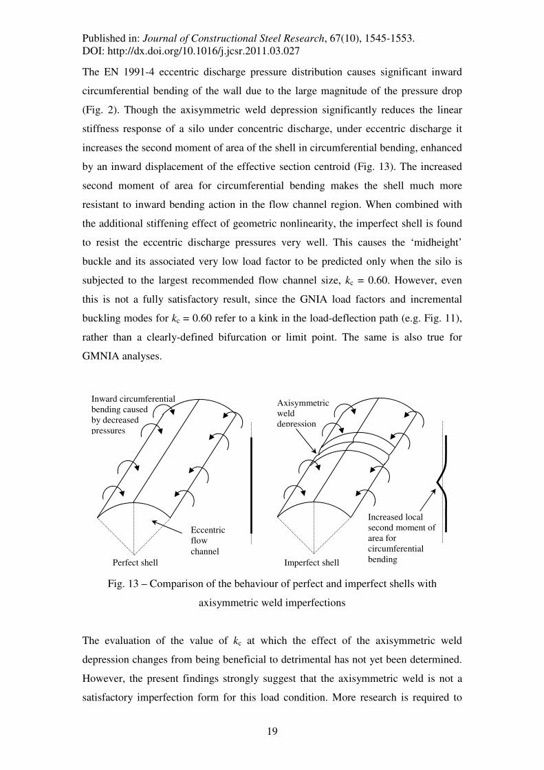
The EN 1991-4 eccentric discharge pressure distribution causes significant inward
circumferential bending of the wall due to the large magnitude of the pressure drop
(Fig. 2). Though the axisymmetric weld depression significantly reduces the linear
stiffness response of a silo under concentric discharge, under eccentric discharge it
increases the second moment of area of the shell in circumferential bending, enhanced
by an inward displacement of the effective section centroid (Fig. 13). The increased
second moment of area for circumferential bending makes the shell much more
resistant to inward bending action in the flow channel region. When combined with
the additional stiffening effect of geometric nonlinearity, the imperfect shell is found
to resist the eccentric discharge pressures very well. This causes the ‘midheight’
buckle and its associated very low load factor to be predicted only when the silo is
subjected to the largest recommended flow channel size, kc = 0.60. However, even
this is not a fully satisfactory result, since the GNIA load factors and incremental
buckling modes for kc = 0.60 refer to a kink in the load-deflection path (e.g. Fig. 11),
rather than a clearly-defined bifurcation or limit point. The same is also true for
GMNIA analyses.
Fig. 13 – Comparison of the behaviour of perfect and imperfect shells with
axisymmetric weld imperfections
The evaluation of the value of kc at which the effect of the axisymmetric weld
depression changes from being beneficial to detrimental has not yet been determined.
However, the present findings strongly suggest that the axisymmetric weld is not a
satisfactory imperfection form for this load condition. More research is required to
Perfect shell Imperfect shell
Increased local
second moment of
area for
circumferential
bending
Axisymmetric
weld
depression
Inward circumferential
bending caused
by decreased
pressures
Eccentric
flow
channel

Published in: Journal of Constructional Steel Research, 67(10), 1545-1553.
DOI: http://dx.doi.org/10.1016/j.jcsr.2011.03.027
20
determine a realistic and deleterious imperfection form for slender silos under the EN
1991-4 eccentric discharge pressures.
9. The effect of material plasticity
In the companion paper, it was shown that the analysis of a silo under concentric
discharge results in a stress state corresponding to uniform axial compression and
internal pressure. Plasticity was thus found to be widespread and interacting closely
with the buckling mode, so that all GMNA and many GMNIA analyses predicted the
elastic-plastic elephant’s foot buckling mode.
The effect of material plasticity appears to be very limited in eccentric discharge
predictions, where the buckling phenomenon has been shown to be predominantly
elastic and caused by locally elevated stress concentrations. High stresses may occur
in the buckled regions leading to local yielding in the perfect structure, which slightly
reduces the predicted buckling strength. Similarly, regions immediately adjacent to
the axisymmetric weld depressions are usually subject to very high local stresses,
leading to yielding in the vicinity of the weld depressions in GMNIA analyses.
Nevertheless, this effect is very minor, though it always reduces the buckling strength.
10. Conclusions
The following conclusions may be drawn based on the results of this study:
1) It was shown in the companion paper that the example silos exhibit significant
reserves of strength under concentric discharge, by over a factor of two
beyond the partial safety factor of the EN 1993-1-6 structural assessment.
However, those same designs have been shown to be completely inadequate
under the EN 1991-4 eccentric discharge condition. Further, this finding has
been shown to be valid throughout a range of slendernesses from very slender
to those bordering on squat.
2) The dominant predicted buckling mode in slender silos under the EN 1991-4
eccentric discharge pressures is the predominantly elastic ‘midheight’
buckling mode. This mode is also widely seen in practice.

Published in: Journal of Constructional Steel Research, 67(10), 1545-1553.
DOI: http://dx.doi.org/10.1016/j.jcsr.2011.03.027
21
3) The most common predicted buckling mode of silos with low aspect ratios
under eccentric discharge is the predominantly plastic ‘base edge’ buckling
mode. This mode is not known to have been observed in practice. The reason
is probably that the EN 1991-4 eccentric discharge model is based on the
assumption of parallel-sided eccentric pipe flow, which is unlikely to develop
in squatter silos. The computational analysis of squat silos under eccentric
discharge therefore requires further study, first in the development of a
pressure model for an appropriate unsymmetrical flow pattern and then
structural analyses to follow this.
4) The predicted buckling strength of a silo under the EN 1991-4 eccentric
discharge pressures is significantly higher when analysed with a geometrically
nonlinear analysis (GNA) than with a linear analysis (LBA). The gain in
strength may be very large (~ 9×) for smaller flow channels (kc = rc/R ≈ 0.25).
5) To obtain the pattern of stresses characteristic of eccentric pipe flow in a
geometrically nonlinear analysis, the flow channel is required to be quite large
(kc ≥ 0.40). In linear analyses, a smaller channel with kc = 0.25 was sufficient.
Geometric nonlinearity therefore produces an important stiffening effect in
silos of all aspect ratios, and its mechanics require further study.
6) Axisymmetric weld depressions have been found to lead to significant strength
gains, especially for smaller flow channels (kc ≤ 0.40). This imperfection form,
so deleterious under axisymmetric loading, has been found to increase the
circumferential bending stiffness of the shell and to enhance the buckling
strength significantly. Only very large flow channels still cause buckling
across the flow channel at midheight when weld depressions are present.
These findings indicate that different imperfection forms are needed when
studying eccentric discharge, and that the underlying assumption of EN 1993-
1-6, that deeper imperfections cause lower buckling loads, is seriously in error
for this load condition.
References
ABAQUS (2009). “ABAQUS Version 6.9” Dassault Systèmes Simulia Corp.,
Providence, RI, USA.

Published in: Journal of Constructional Steel Research, 67(10), 1545-1553.
DOI: http://dx.doi.org/10.1016/j.jcsr.2011.03.027
22
Ayuga F., Guaita M., Aguado P.J. & Cuoto A. (2001). “Discharge and the
Eccentricity of the Hopper Influence on the Silo Wall Pressures.” Jrnl of Eng. Mech.,
ASCE, 127(10), 1067-1074.
Calladine C. R. (1983). “Theory of Shell Structures” Cambridge University Press,
Cambridge.
Chen J.F. (1996). “Granular Solid - Structure interaction in Silos” PhD Thesis, The
University of Edinburgh, UK.
Chen J.F., Rotter J.M., Ooi J.Y. & Zhong Z. (2007). “Correlation between the flow
pattern and wall pressures in a full scale silo.” Engineering Structures, 29, 2308-2320.
Chrisp T.M., Wood J.G.M. & Blacker M.J. (1988). “Comparison of model and full-
scale test results with simplified and finite element analyses of eccentrically
discharged silos” Silos - Forschung und Praxis, University of Karlsruhe, Germany.
EN 1991-4 (2006). “Eurocode 1: Actions on Structures, Part 4: Silos and Tanks.”
European Committee for Normalisation, Brussels.
EN 1993-1-6 (2007). “Eurocode 3: Design of Steel Structures, Part 1-6: Strength and
Stability of Shell Structures.” Comité Européen de Normalisation, Brussels.
EN 1993-4-1 (2007). “Eurocode 3: Design of Steel Structures, Part 4-1: Silos.”
Comité Européen de Normalisation, Brussels.
Hampe E. (1987). “Silos, Band 1 - Grundlagen.” VEB Verlag für Bauwerke, Berlin.
Holst J.M.F.G., Ooi J.Y., Rotter J.M. & Rong G.H. (1999a). “Numerical Modelling of
Silo Filling. I: Continuum Analyses.” Jrnl of Eng. Mech., ASCE, 125(1), 94-103.
Holst J.M.F.G., Ooi J.Y., Rotter J.M. & Rong G.H. (1999b). “Numerical Modelling of
Silo Filling. II: Discrete Element Analyses.” Jrnl of Eng. Mech., ASCE, 125(1), 104-
110.
Published in: Journal of Constructional Steel Research, 67(10), 1545-1553.
DOI: http://dx.doi.org/10.1016/j.jcsr.2011.03.027
23
Jenike A.W. (1967). “Denting of Circular Bins with Eccentric Drawpoints” J. of the
Struct. Div., ASCE, 93 (ST1) 27-35.
Knödel, P., Ummenhofer, T. & Schulz, U. (1995). “On the Modelling of Different
Types of Imperfections in Silo Shells.” Thin-Walled Structures, 23, 283-293.
Rotter J.M. (1986). “The analysis of steel bins subject to eccentric discharge.” Proc.
of the 2nd
Int. Conf. on Bulk Materials Storage, Handling and Transportation,
IEAustralia, Wollongong, 264-271.
Rotter J.M. (1990). “Local inelastic collapse of pressurised thin cylindrical steel shells
under axial compression.” Jrnl of Struct. Eng., ASCE, 116(7), 1955-1970.
Rotter J.M. (2001a). “Guide for the Economic Design of Circular Metal Silos.”, Spon
Press, London & New York.
Rotter J.M. (2001b). “Pressures, Stresses and Buckling in Metal Silos containing
Eccentrically Discharging Solids.” Festschrift Richard Greiner, Celebration volume
for the 60th
birthday of Prof. Richard Greiner, TU Graz, Austria, October, 85-104.
Rotter J.M. (2006). “Elephant’s foot buckling in pressurised cylindrical shells.”,
Stahlbau, Vol 75, Heft 9, 742-747.
Rotter J.M. & Teng J.G. (1989). “Elastic stability of cylindrical shells with weld
depressions.” Jrnl of Struct. Eng., ASCE, 115(5), 1244-1263.
Rotter J.M. & Zhang Q. (1990). “Elastic buckling of imperfect cylinders containing
granular solids.” Jrnl of Struct. Eng., ASCE, 116(8), 2253-2271.
Sadowski A.J. (2010). “Modelling of Failures in Thin-Walled Metal Silos under
Eccentric Discharge.” PhD Thesis, The University of Edinburgh, UK.

Published in: Journal of Constructional Steel Research, 67(10), 1545-1553.
DOI: http://dx.doi.org/10.1016/j.jcsr.2011.03.027
24
Sadowski A.J. & Rotter J.M. (2010). “A Study of Buckling in Steel Silos under
Eccentric Discharge Flows of Stored Solids.” Jrnl of Eng. Mech., ASCE, 136(6), 769-
776.
Sadowski A.J. & Rotter J.M. (2011). “Buckling of very slender metal silos under
eccentric discharge.” Engineering Structures, 33(4), 1187-1194.
Sanad A.M., Ooi J.Y., Holst J.M.F.G. & Rotter J.M. (2001). “Computations of
Granular Flow and Pressures in a Flat-Bottomed Silo.” Jrnl of Eng. Mech., ASCE,
127(10), 1033-1043.
Yamaki N. (1984). “Elastic Stability of Circular Cylindrical Shells.” Elsevier Applied
Science Publishers, Amsterdam.
Zhong Z., Ooi J.Y. & Rotter J.M. (2001). “The Sensitivity of Silo Flow and Wall
Stresses to Filling Method.” Engineering Structures, 23, 756-767.