manufacturing of custom-made parts for assembly of large
TRANSCRIPT

Procedia Engineering 132 ( 2015 ) 1006 – 1013
1877-7058 © 2015 The Authors. Published by Elsevier Ltd. This is an open access article under the CC BY-NC-ND license (http://creativecommons.org/licenses/by-nc-nd/4.0/).Peer-review under responsibility of the Scientific Committee of MESIC 2015doi: 10.1016/j.proeng.2015.12.589
ScienceDirectAvailable online at www.sciencedirect.com
The Manufacturing Engineering Society International Conference, MESIC 2015
Manufacturing of custom-made parts for assembly of large aircraft components
A. Gómeza, V. Olmosb, J. Racerob, J. Ríosa, R. Aristac, F. Masc,*
aDept. of Mechanical Engineering, Universidad Politécnica de Madrid, José Gutiérrez Abascal, 2, 28006 Madrid, Spain bFIDETIA, Avda. Reina Mercedes s/n, 41012 Sevilla
cAirbus Group. Carretera A8010, km.4, 41020 Sevilla, Spain
Abstract
The manufacturing of custom-made parts requires the development of strategies integrating design and manufacturing. The need for custom-made parts is increasing constantly due to its application in different industrial sectors: medical prosthesis, car parts, aircraft parts, etc. Under such context, this paper describes a part of the MISTRAL (Methods of InverSe engineering To develop RApid prototyping tooLs) project. Taking a file with clouds of points as main input, the aim was to generate CAD models and machining process plans for custom-made parts. The parts are different for every aircraft produced, since they have to fit in with large components, whose real geometry is subject to variable deformation states in the assembly process. This paper presents a prototype development carried out mainly in CATIA v5. The developed solution was tested with a typical family of parts. © 2016 The Authors. Published by Elsevier Ltd. Peer-review under responsibility of the Scientific Committee of MESIC 2015.
Keywords: surface reconstruction; custom-made manufacturing; reverse engineering; CAD VBA macro development
1. Introduction
Manufacturing in the aerospace sector involves the assembly of components with large dimensions and shapes that cause significant deformations under their own weight. Therefore, the tolerances of the physical part-to-part interface differ from the estimated during the design process. That is particularly significant for components
* Corresponding author. Tel.: +34 619 215 699 E-mail address: [email protected]
© 2015 The Authors. Published by Elsevier Ltd. This is an open access article under the CC BY-NC-ND license (http://creativecommons.org/licenses/by-nc-nd/4.0/).Peer-review under responsibility of the Scientific Committee of MESIC 2015

1007 A. Gómez et al. / Procedia Engineering 132 ( 2015 ) 1006 – 1013
belonging to the wings structures and their joints with the fuselage [1]. Fig. 1 shows custom-made components in an aircraft.
Fig. 1. An example of ad hoc aircraft interface parts.
Consequently, the geometry of the interfaces between components of this type is specific for each produced aircraft. Parts manufactured using only the aircraft model Digital Mock-Up (DMU) will not fit properly in the available physical space of a specific aircraft. To solve this problem a possible solution is to machine ad hoc parts using reverse engineering techniques [2], [3].
In general, the process to obtain these parts involves capturing the geometry of the contact surfaces, typically by a process called photogrammetry, which obtains the coordinates of a number of points [4]. Once the geometric data is obtained, the rest of the system is independent of the point coordinates capturing method. Geometric captured information needs to be filtered to discard wrong data or noise [5]. The next step is to reconstruct the part CAD model from such data [6], [7]. This approach is used in different types of components ranging from aircraft parts, both structural and engine parts, to human prosthesis [8], [9].
Within the described context, this work focuses on the development of a semiautomatic process, implemented into a commercial CAD/CAM system (CATIA v5), whose main input is a file containing coordinates of points, to create a part 3D model and its corresponding machining NC code. The work is part of the MISTRAL research project.
Fig. 2. Activity diagram of the complete process in MISTRAL.
1.1. The MISTRAL Project
MISTRAL is a collaborative research project involving several organizations and led by AIRBUS Group. One subpart of MISTRAL deals with the development of a solution to create a 3D model from data of a cloud of points, define the machining process and the ISO NC program to manufacture ad hoc aeronautical components. Due to the industrial constraints, such development had to be carried out into the commercial software system CATIA v5. At the early stages of the project, the required process was divided into three different blocks, as shown in Fig. 2. The system requires two main inputs: measures of the physical parts, currently obtained by photogrammetry and probing, and reference digital models of the machining process and auxiliary geometry. The outputs are digital models of the reconstructed surface and 3D part, as well as the machining process and the NC ISO program code.
Measures from probing

1008 A. Gómez et al. / Procedia Engineering 132 ( 2015 ) 1006 – 1013
The antecedent of this work was a set of modules, comprising different black-box software tools. Such tools were not fully integrated within CATIA v5. Several utilities: the filtering of the points cloud data, the surface reconstruction, the final 3D part creation, the definition of the machining process and the NC code generation; required new approaches and a partial or complete new development.
1.2. Objective
The main target was to develop an automatic prototype solution to design and manufacture ad hoc aeronautical parts, e.g.: splice, upper butt-strap, corner fitting, build door and crown fittings. The solution had to be implemented into CATIA v5, the commercial software used in the design of the aircraft aero structures. The splice part family was selected for this subpart of MISTRAL, to identify the main requirements and to test and validate the adopted approach and the developed software solution. The main input is a file containing the coordinates of each point of the point cloud. Such file could be obtained by different scanning methods, and that was out of the scope of the project.
2. Methodology
The development was divided into three main modules, each one corresponding to the blocks depicted in the Fig. 2. The section 2.1 presents the overall process to be executed and supported by the three main modules, which are also described. The section 2.2 presents the implementation of the three defined modules.
2.1. Process
The overall procedure comprises several phases. Currently, once the components to join are correctly positioned, geometric data are captured into point clouds using photogrammetry. The point clouds are filtered and some key surfaces are generated from them. Then the final 3D geometry of the part is created. Once the design activities of the process are finalised, the manufacturing activities are carried out. Machining operations adapted to the final 3D part design are created by means of a set of user pre-defined macros, then the machining process is simulated and when approved, the ISO NC code for the machining process is generated, simulated and validated.
Filtering faulty points: The first module of the development deals with the captured geometric data. The main input of the system is the
set of points captured from the surface of the junction interface where the part will fit in. These points are currently captured by photogrammetry, using target sheets stuck to the surface. The sheets coordinates are calculated and stored. These captured points are grouped into sets called point clouds, each cloud is related with one element to be reconstructed: a surface or the reference drills of a surface.
Independently of the method used to capture the point clouds, the captured data must be checked and filtered to eliminate possible wrong measures. Physical defects, for instance, in the case of the current method, small air bubbles under any sheet, may cause wrong measures [5]. The cloud points have to pass three filters. The first one checks if points are between two theoretical surfaces separated by a reference distance. The second filter checks the cloud smoothness: the ratio of values of flatness of given sections of the cloud with and without every point within a reference tolerance. The number of sections is adjustable. The third filter checks the curvature at each point. The curvature at each point is estimated before reconstructing the surface itself, by calculating the curvature radius of the curves that contain the point and its neighbors [9]. The minimum obtained value must be larger than a defined reference parameter.
Creating the part 3D digital model: In the second module, the 3D digital part is generated. Filtered points are used to reconstruct key surfaces and the
drill grids position over them. The geometry required in the module 2 is generated in different operations. During the process, a new CATIA file is automatically created. The file is used as a working document, to create and load geometry and to perform the required operations. At the end of the module, the proper elements are copied to the output files. Fig. 3 shows the flow diagram followed in the module 2, with the input and output objects.
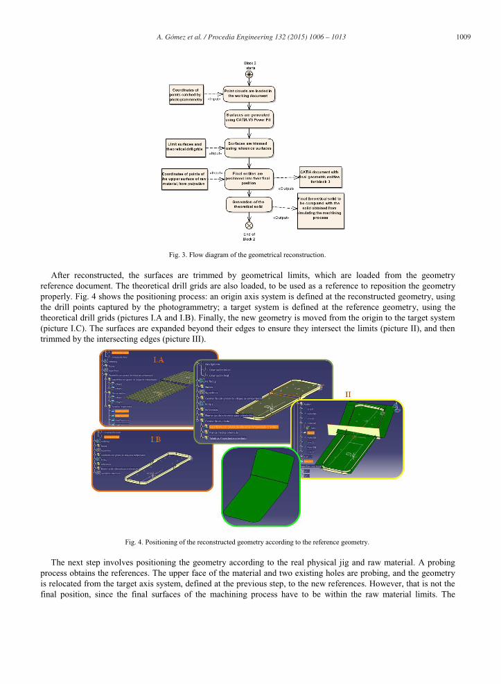
1009 A. Gómez et al. / Procedia Engineering 132 ( 2015 ) 1006 – 1013
Fig. 3. Flow diagram of the geometrical reconstruction.
After reconstructed, the surfaces are trimmed by geometrical limits, which are loaded from the geometry reference document. The theoretical drill grids are also loaded, to be used as a reference to reposition the geometry properly. Fig. 4 shows the positioning process: an origin axis system is defined at the reconstructed geometry, using the drill points captured by the photogrammetry; a target system is defined at the reference geometry, using the theoretical drill grids (pictures I.A and I.B). Finally, the new geometry is moved from the origin to the target system (picture I.C). The surfaces are expanded beyond their edges to ensure they intersect the limits (picture II), and then trimmed by the intersecting edges (picture III).
Fig. 4. Positioning of the reconstructed geometry according to the reference geometry.
The next step involves positioning the geometry according to the real physical jig and raw material. A probing process obtains the references. The upper face of the material and two existing holes are probing, and the geometry is relocated from the target axis system, defined at the previous step, to the new references. However, that is not the final position, since the final surfaces of the machining process have to be within the raw material limits. The
1010 A. Gómez et al. / Procedia Engineering 132 ( 2015 ) 1006 – 1013
geometry is perpendicularly moved a distance towards the inside of the material limits. The distance is given by the reconstruction criteria: “minimum weight” for thinner parts, or “minimum shaving” for thicker parts with less machining required.
The module 2 has two outputs. The final geometrical entities generated in the working CATPart document are copied to a new document, which is the input to the next module. These entities are the final surfaces, the edge curves, the directions tangent to those curves, the drill points and the drill axis. Fig. 5 shows the final entities reconstructed for one of the parts. Fig. 6 shows the theoretical solid 3D model to be obtained from the machining process.
Fig. 5. Final geometrical entities generated. Fig. 6. Theoretical volume to be obtained by machining.
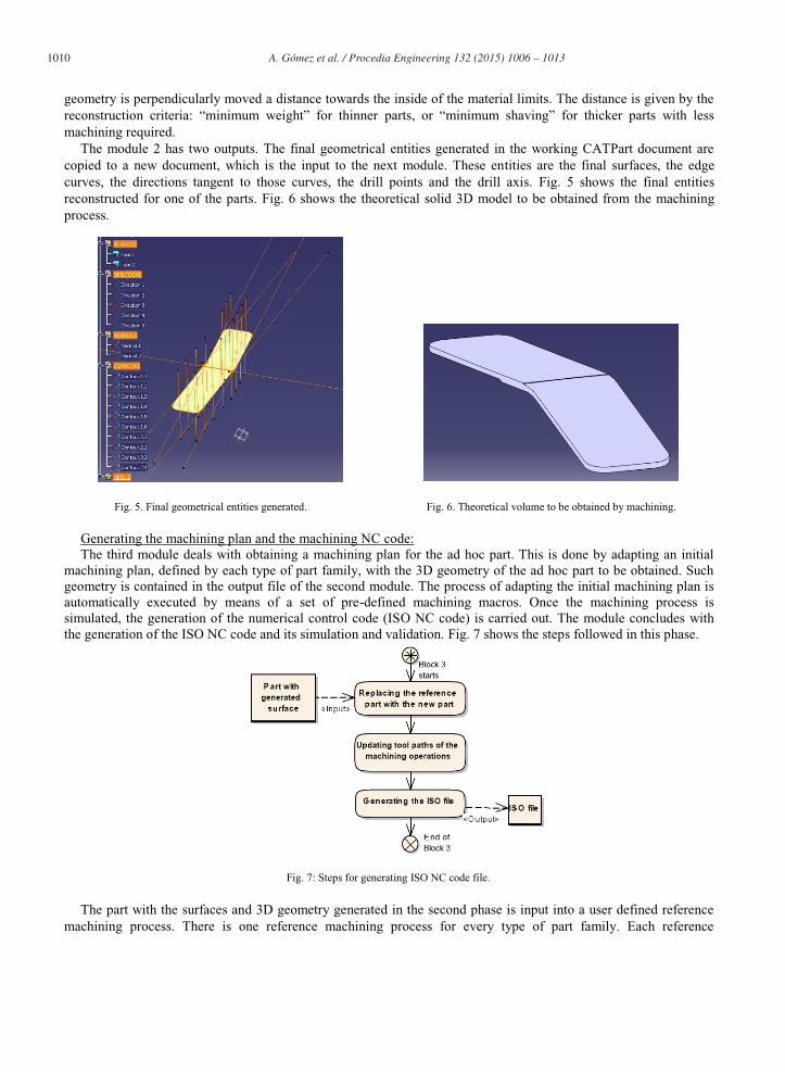
Generating the machining plan and the machining NC code: The third module deals with obtaining a machining plan for the ad hoc part. This is done by adapting an initial
machining plan, defined by each type of part family, with the 3D geometry of the ad hoc part to be obtained. Such geometry is contained in the output file of the second module. The process of adapting the initial machining plan is automatically executed by means of a set of pre-defined machining macros. Once the machining process is simulated, the generation of the numerical control code (ISO NC code) is carried out. The module concludes with the generation of the ISO NC code and its simulation and validation. Fig. 7 shows the steps followed in this phase.
Fig. 7: Steps for generating ISO NC code file.
The part with the surfaces and 3D geometry generated in the second phase is input into a user defined reference machining process. There is one reference machining process for every type of part family. Each reference
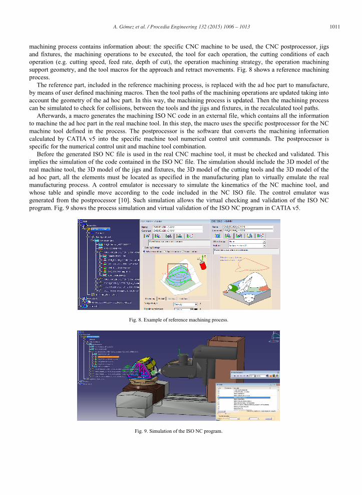
1011 A. Gómez et al. / Procedia Engineering 132 ( 2015 ) 1006 – 1013
machining process contains information about: the specific CNC machine to be used, the CNC postprocessor, jigs and fixtures, the machining operations to be executed, the tool for each operation, the cutting conditions of each operation (e.g. cutting speed, feed rate, depth of cut), the operation machining strategy, the operation machining support geometry, and the tool macros for the approach and retract movements. Fig. 8 shows a reference machining process.
The reference part, included in the reference machining process, is replaced with the ad hoc part to manufacture, by means of user defined machining macros. Then the tool paths of the machining operations are updated taking into account the geometry of the ad hoc part. In this way, the machining process is updated. Then the machining process can be simulated to check for collisions, between the tools and the jigs and fixtures, in the recalculated tool paths.
Afterwards, a macro generates the machining ISO NC code in an external file, which contains all the information to machine the ad hoc part in the real machine tool. In this step, the macro uses the specific postprocessor for the NC machine tool defined in the process. The postprocessor is the software that converts the machining information calculated by CATIA v5 into the specific machine tool numerical control unit commands. The postprocessor is specific for the numerical control unit and machine tool combination.
Before the generated ISO NC file is used in the real CNC machine tool, it must be checked and validated. This implies the simulation of the code contained in the ISO NC file. The simulation should include the 3D model of the real machine tool, the 3D model of the jigs and fixtures, the 3D model of the cutting tools and the 3D model of the ad hoc part, all the elements must be located as specified in the manufacturing plan to virtually emulate the real manufacturing process. A control emulator is necessary to simulate the kinematics of the NC machine tool, and whose table and spindle move according to the code included in the NC ISO file. The control emulator was generated from the postprocessor [10]. Such simulation allows the virtual checking and validation of the ISO NC program. Fig. 9 shows the process simulation and virtual validation of the ISO NC program in CATIA v5.
Fig. 8. Example of reference machining process.
Fig. 9. Simulation of the ISO NC program.
1012 A. Gómez et al. / Procedia Engineering 132 ( 2015 ) 1006 – 1013
2.2. Implementation
The modules were mainly implemented within CATIA v5, except the algorithms for the filtering of the photogrammetry cloud points. The points filtering step was develop as an autonomous application, which can be executed independently of any other application, so it is possible to execute it in a computer without having CATIA installed. This approach allowed creating a file with the filtered and ordered cloud of points and importing it into CATIA v5. The file with the coordinates of the cloud points could also be obtained from different scanning systems.
The digital part reconstruction was programmed by means of macros using the CATIA VBA Application Programming Interface. The developed code uses classes and functions from the Part Design area: some of them belonging to the class HybridShapeFactory, to create non solid geometry, and others from ShapeFactory, to operate with solids. Using Visual Studio, a prototype application was developed, incorporating the module 2 functionalities.
The use of the command Power Fit (to generate NURBS surfaces from point clouds) and the curvature analysis were automated with the function “StartCommand” and using the Windows API to capture the open dialog boxes. A CATPart file with all the ad hoc part 3D geometry is created by executing the prototype application.
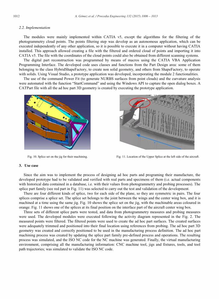
Fig. 10. Splice set on the jig for their machining. Fig. 11. Location of the Upper Splice at the left side of the aircraft.
3. Use case
Since the aim was to implement the process of designing ad hoc parts and programing their manufacture, the developed prototype had to be validated and verified with real parts and specimens of them (i.e. actual components with historical data contained in a database, i.e. with their values from photogrammetry and probing processes). The splice part family (see red part in Fig. 11) was selected to carry out the test and validation of the development.
There are four different kinds of splice, two for each side of the plane, so they are symmetric in pairs. The four splices comprise a splice set. The splice set belongs to the joint between the wings and the center wing box, and it is machined at a time using the same jig. Fig. 10 shows the splice set on the jig, with the machinable areas coloured in orange. Fig. 11 shows one of the splices at its final position on the interface part of the aircraft center wing box.
Three sets of different splice parts were tested, and data from photogrammetry measures and probing measures were used. The developed modules were executed following the activity diagram represented in the Fig. 2. The measured points were filtered. The filtered points were used to create the ad hoc part surfaces. The created surfaces were adequately trimmed and positioned into their final location using references from probing. The ad hoc part 3D geometry was created and correctly positioned to be used in the manufacturing process definition. The ad hoc part machining process was created by updating the splice part family pre-defined process and operations. The resulting process was simulated, and the ISO NC code for the NC machine was generated. Finally, the virtual manufacturing environment, comprising all the manufacturing information: CNC machine tool, jigs and fixtures, tools, and tool path trajectories; was simulated to validate the ISO NC code.

1013 A. Gómez et al. / Procedia Engineering 132 ( 2015 ) 1006 – 1013
4. Results and Discussion
The prototype was tested for specimens of the splice part family. Different issues arose along the development and testing process, mainly dealing with geometry computation. The testing process allowed identifying the issues that needed further development to make the prototype more generic in the coding solution and robust. The development is independent of the technique used to generate the file with the clouds of points.
The execution of the three sets of splice components resulted in correct outcomes, proving that the implementation of the proposed system into the software CATIA v5 is feasible. Although, the developed solution allows obtaining adequate results, some changes and adjustments in the prototype are still required in order to get a better performance. The accuracy used in the surface reconstruction of the part geometry is in the order of hundredths of millimetre.
5. Conclusions
This work presents a semiautomatic process for manufacturing custom-made parts, implemented into the commercial system CATIA v5. Its originality resides in the development to automate the part geometry reconstruction.
A prototype was developed, and although a limited number of tests were performed, it demonstrates that the designed system can be implemented with adequate results. Tests also showed that an adaptation of some involved reference files is required.
A future work is to test, and eventually to adapt, the prototype-developed code to a wider set of custom-made part families. The scope of the MISTRAL project comprises a wider set of part families. The designed activity and flow diagram would be the same, but sections of the developed code needs to be adapted to each part family.
Acknowledgements
The MISTRAL project was funded by the FEDER-INNTERCONECTA program, which is coordinated by The Centre for Industrial Technological Development (CDTI, in Spanish). Authors thank their colleagues from FIDETIA, FADA-CATEC and AIRBUS Group for their contributions and kind collaboration.
References
[1] M. Saadat, C. Creting, Dimensional variations during Airbus wing assembly, Assembly Automation, 22 (2002), pp. 270-276. [2] Z. Yu, Research into the engineering application of reverse engineering technology, Journal of Materials Processing Technology, 139 (2003),
pp. 472-475. [3] J. Jamshidi, et al., Manufacturing and assembly automation by integrated metrology systems for aircraft wing fabrication, J. of Engineering
Manufacture, 224 (2010), pp. 25-36. [4] T. Liu et.al., Photogrammetric techniques for aerospace applications, Progress in Aerospace Sciences 54 (2012), pp. 1–58 [5] O. Schall et.al., Robust Filtering of Noisy Scattered Point Data, Eurographics Symposium on Point-Based Graphics, 2005. [6] Z. Yin, Reverse engineering of a NURBS surface from digitized points subject to boundary conditions, Computers & Graphics, 28 (2004),
pp. 207–212. [7] S.-H. Bae, NURBS surface fitting using orthogonal coordinate transform for rapid product development, Computer Aided Design, 34 (2002),
pp. 683-690. [8] J. Gao, et al., An integrated adaptive repair solution for complex aerospace components through geometry reconstruction, Int. J. Adv.
Manufacturing Technology, 36 (2008), pp. 1170-1179. [9] J.-N. Lee, et al., Developing the custom-made femoral component of knee prosthesis using CAD/CAM, Life Science Journal, 10 (2013), pp.
259-264. [10] ICAM. (2015). Control Emulator, G-Code machine simulation, Emulation. Retrieved March 6, 2015, from
http://www.icam.com/html/products/control_emulator.php