manufacturing & assembly for vacuum technology · brazing & soldering vacuum brazing...
TRANSCRIPT

1EN/MME- CAS June 2017
Manufacturing & Assembly
for Vacuum Technology
S. Atieh, G. Favre, S. Mathot
(For the EN/MME group)

2EN/MME- CAS June 2017
Outline:
Manufacturing
Introduction
Precision turning
Precision milling
Affected layer
Diamond tools ultraprecision
Milling (Machine) center
Ceramic machining
Cutting fluids
Avoided or less appropriate techniques
Sheet metal forming
Assembly
TIG welding
MIG welding
Electron and Laser welding
Welding defects
Brazing & Soldering
Vacuum brazing
Ceramic / metal vacuum brazing
Vacuum soldering
Diffusion brazing & Diffusion bonding
Present trends and future perspectives
Final remarks - comments

3EN/MME- CAS June 2017
Manufacturing – Introduction
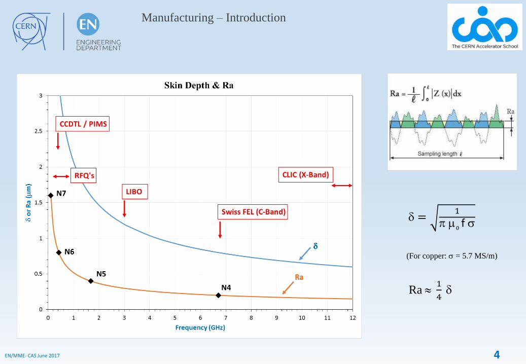
° An interpretation of the Taniguchi curves,
made in 1983, depicting the general
improvement of machine accuracy
capability with time during much of the
twentieth century.
4EN/MME- CAS June 2017
Manufacturing – Introduction
d =1
p m0f s
(For copper: s = 5.7 MS/m)
Ra 1
4d
5EN/MME- CAS June 2017
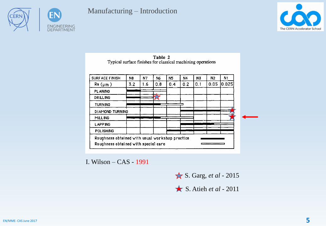
I. Wilson – CAS - 1991
S. Garg, et al - 2015
S. Atieh et al - 2011
Manufacturing – Introduction

6EN/MME- CAS June 2017
Manufacturing – Precision turning
° For axial-symmetry part
° Continuous process (single edge remove all the material)
• Chip control for process reliability and workpiece quality
• Chatter geometry + surface quality control
• Achievable performance on state-of-the-art equipment
• Shape accuracy 10 µm
• Roughness < Ra 0.2 µm (OFE Cu)
7EN/MME- CAS June 2017
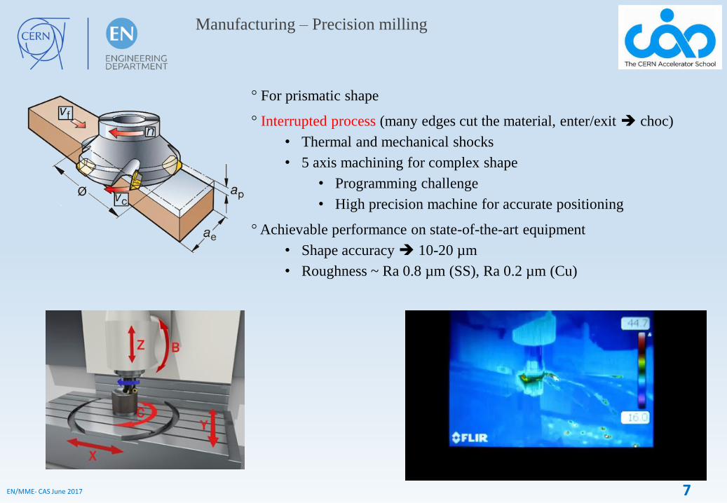
° For prismatic shape
° Interrupted process (many edges cut the material, enter/exit choc)
• Thermal and mechanical shocks
• 5 axis machining for complex shape
• Programming challenge
• High precision machine for accurate positioning
° Achievable performance on state-of-the-art equipment
• Shape accuracy 10-20 µm
• Roughness ~ Ra 0.8 µm (SS), Ra 0.2 µm (Cu)
Manufacturing – Precision milling

8EN/MME- CAS June 2017
ap
Recrystallized
layer
Mechanical
modified
properties
Affected layer
(0-100 µm)
Vc : speed rate (m.min-1)
f : feed rate (mm.tr-1)
ap : depth of cut (mm)
rε : nose radius (mm)
EM : state of matter (annealing, stress
relieving, ¼ hard)
EM Visible affected layer in case of hard turning parameters. (ap = 2 mm, f = 0.35 mm.tr -1, Vc = 300 m.min-1)
1st results : typical parameters for RF cavities
• Tool : VCGT160404, ap = 0.3 mm, f = 0.05 mm.tr -1 , Vc =160 m.min-1, EM = ¼ hard ;
• No recrystallized layer observed ;
• Study on going : development of a way of characterizing affected layer by microscopic analysis ;
- EBSD / BS (Band Slope) criterion : use to distinguish identical crystalline structure with different
density of dislocation => Density of dislocation more significant under surface than in the bulk.
- Nano-hardness measurement and FIB to correlate and validate results
Manufacturing – Affected layer
° To be considered, mainly if coating is needed after machining.
° Each machining process has “its” damaged layer!

9EN/MME- CAS June 2017
Manufacturing – Diamond tools ultraprecision
Turning / Milling (For non ferrous metals only!)
5 µm

10EN/MME- CAS June 2017
° Diamond cutting is greatly restricted in ferrous material machining because there is a high chemical reactivity
between diamond and iron that causes a catastrophic tool wear. The wear process involves the initial
transformation of tetrahedral diamond into hcp graphite (graphitization) catalysed by the clean surface of iron
and ambient oxygen (oxidation). Finally, there is a diffusion of graphitic carbon into the iron workpiece, quickly
eroding the diamond surface. At this stage, diamond tool wear is unstable and impossible to predict with an
exact value.
Simulation of graphitic diffusion in orthogonal
machining. Carbon atoms are shown in cyan
color and iron atoms are shown in ochre colour
(Narulkar, Bukkapatnam, Raff, & Komanduri,
2009).
° Diamond turning / milling needs dedicated machine!
Manufacturing – Diamond tools ultraprecision
Turning / Milling (For non ferrous metals only!)

11EN/MME- CAS June 2017
Manufacturing – Milling (Machine) Center
HL-LHC - D2Q4 winding prototype
Hermle C42U (CERN)

12EN/MME- CAS June 2017
Manufacturing – Ceramic machining
Diamond tool (cutter)

13EN/MME- CAS June 2017
Manufacturing – Cutting fluids
Ideally, oil-free fluids, fully water soluble, and efficiently removed by solvents – To be tested!
° If possible, finishing by dry-machining or
using ethanol as cutting fluid.
° Example:Mineral oil-based coolant, Blasocut
BC 35 LF SW, without additives containing
sulphur, chlorine, zinc or phosphor. Qualified,
by the CERN surface treatment service, as
adapted for UHV parts produced by milling
and turning.

14EN/MME- CAS June 2017
Manufacturing – Avoided or less appropriate techniques
° Polishing – Or with appropriate material (SiC*, Alumina*, Diamond) , Chemical polishing
* Caution in case of RF field
° Water, Laser, Plasma cutting – Only for rough machining
° Grinding (abrasive) cutting, honing machining
° Electrical Discharge Machining** (EDM)
** Mainly with wire, and if the wire contains Zn (Brass)!
** Non ideal surface state for vacuum!
Charmilles Technologies Robofil 510 (CERN)

15EN/MME- CAS June 2017
Manufacturing – Sheet metal forming
° Spinning – Pressing – Deep drawing – Hydroforming ….
° Extrusions:
Significantly reduces
deformations and easier
the welding operation.

16EN/MME- CAS June 2017
Assembly – TIG welding
° Tungsten Inert Gas welding (gas tungsten arc welding)

17EN/MME- CAS June 2017
Assembly – TIG welding
° Tungsten Inert Gas welding (gas tungsten arc welding)
Weld preparation
Correct Incorrect
VacuumVacuum
Vacuum Vacuum
Vacuum
Vacuum Vacuum
Vacuum Vacuum
* Air side welding can be accepted if discontinue (for mechanical reinforcement).
Vacuum
Vacuum Vacuum

18EN/MME- CAS June 2017
Assembly – MIG welding
° Metal Inert Gas welding (gas metal arc welding)

19EN/MME- CAS June 2017
Assembly – Electron and Laser welding
° Electron beam machine
(Vacuum chamber)
° Laser beam machine
(Gas protection)
20EN/MME- CAS June 2017
Assembly – Electron and Laser welding
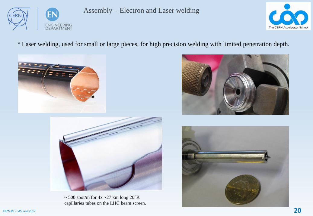
° Laser welding, used for small or large pieces, for high precision welding with limited penetration depth.
~ 500 spot/m for 4x ~27 km long 20°K
capillaries tubes on the LHC beam screen.

21EN/MME- CAS June 2017
Assembly – Electron and Laser welding
° Electron beam welding, for high precision welding or high penetration depth. Welding of large pieces is
limited or need special adaptations.

22EN/MME- CAS June 2017
Welding defects*
Hot cracking
Non metallic inclusions
(Base material defects)
Shrinkage holes/voids
Lack of fusion
Quality of the welding procedure AND of the base materials (purity) are important.
(* see S. Sgobba lecture)

23EN/MME- CAS June 2017
Assembly – Brazing & Soldering
° Brazing & Soldering: Assembly with a filler metal having a melting point lower than for the assembled materials
° Soldering: Melting point of the filler metal < 450 °C, Brazing: > 450 °C.
° Allow the assembly of different metals and no-metals (ceramics).
° Allow high precision assembly.
° Mechanical resistance generally less than for welding.
° Wetting of the filler metal obtained using a flux or with vacuum / reductive atmosphere (and coating if needed).
Time
Tem
per
atu
re
Vacuum brazing & solderingAir brazing & soldering

24EN/MME- CAS June 2017
Assembly – Vacuum brazing
° Main advantage: Oxide reduction at high temperature / low O2 partial pressure
Gibbs energy of metal oxide formations:
→
G = H – TS H = U + PV
For the reaction: 2
OCu 4O2
Cu 2
STHG 0 BTAG 0
TdT
pCTdTpCG
0
At equilibrium, for the production of one mole of O2:
P
PORT
TG Teq ).,(2ln0
)(2
If : ).,(2
)(2
TeqOP
TOP
).,(2
)(2
TeqOP
TOP
→
→
The oxide is stable
The oxide decompose
For CuO2, A= -169881 and B= 74.43 [Source: CRC Handbook]
At 800°C, G = -90 kJ G = -180 kJ for 1 mole of O2.
With G = -180 kJ,
With P = 760 Torr,
9107.1.)(2 P
PO eq
)(6103.1.)(
2
TorreqO
P

25EN/MME- CAS June 2017
Assembly – Vacuum brazing

26EN/MME- CAS June 2017
2OCu 4O
2Cu 2
For CuO2, A= -169881 and B= 74.43 [Source: CRC Handbook]
At 800°C, G = -90 kJ G = -180 kJ for 1 mole of O2.
With G = -180 kJ,
With P = 760 Torr,
9107.1.)(2 P
PO eq
)(6103.1.)(
2
TorreqO
P
Assembly – Vacuum brazing
2O Al
3
43
O2
Al 3
2
For Al2O3, A= -1689572 and B= 328.66 [Source: CRC Handbook]
At 800°C, G = -1337 kJ G = -891 kJ for 1 mole of O2.
With G = -893 kJ,
With P = 760 Torr,
44104.3.)(2 P
PO eq
)(41105.2.)(
2
TorreqO
P Ellingham diagram

27EN/MME- CAS June 2017
Assembly – Vacuum brazing
° Wetting is generally excellent.
° Brazing on large surfaces possible.
° Allow very good thermal and electrical contacts.
° Assembly clean and UHV compatible.
(Filler metal and material with low vapor pressures!)
° Dissimilar materials can be join.
° Allow high precision assembly with little or no
distortion of the components
But:
° Heat treatment can affect the properties of
the base materials.
° Mechanical tolerances are tight
Filler metal seen on
the vacuum side
Filler Metal Gap Ideal Brazing Temp.
(mm) (mm) (°C)
Cu 0-0.05 0.025 >1083
Ag-Cu (Pd) 0-0.05 0.025 795 - 820
Au-Cu 0.03-0.1 0.05 >920
Ni-Cr 0.03-0.1 0.05 >1050

28EN/MME- CAS June 2017
Assembly – Vacuum brazing
° Joint configuration:
- Groove, no gap (Ra 0.8 µm)
- Groove on a diameter
- Chamfer
- Foil
- Paste

29EN/MME- CAS June 2017
Assembly – Vacuum brazing
° Dissimilar metals:
Nb – Stainless steel
Cu – Stainless steel - Ti
Mo – Stainless steel
Be - Cu – Stainless steel
Glidcop - CuNi Cu – W

30EN/MME- CAS June 2017
Assembly – Ceramic / metal vacuum brazing
° Ceramic (Alumina) / metal brazing:
First process = Mo-Mn metallization
Mo + MnO (Mn) powder on alumina (Al2O3) @ T > 1200 °C and PH2O / PH2 > 10-4 induce:
- Mo reduction and MnO/Al2O3/SiO2… vitreous phase formation.
- Interaction with the Alumina base material and the binder.
- Sintering of the Mo powder in the vitreous phase during cooling.
- Formation of Mo-Mn layer strongly adhering the support.
- Ni layer added to improve the brazing.

31EN/MME- CAS June 2017
° Ceramic (Alumina) / metals brazing: First process = Mo-Mn metallization
Metal thermal expansion AND metal yield strength should be take into account for Metal / Alumina brazing.
Métal TCF
Niobium
Platine
Tantale
Cuivre
Titane
Kovar
Nickel
CuNi
Fe-42Ni
Monel
Invar
Molybdène
Inox 304
Inconel 600
Tungstène
88
33
28
20
8.8
7.7
6.7
4.8
4.5
4.0
3.7
3.5
2.9
2.1
2.0
Higher Thermomechanical Compatibility Factor
(TCB) means reduced stress after brazing.
Assembly – Ceramic / metal vacuum brazing

32EN/MME- CAS June 2017
° Brazing on MoMn metallized Alumina
Cu – Alumina (up to diameter 400 mm!)
Ti – Alumina – Cu
Kovar (Dilver) – Alumina
Assembly – Ceramic / metal vacuum brazing

33EN/MME- CAS June 2017
° Ceramic / metal brazing:
Second process = Active Brazing
- Brazing alloy containing reductive metal: Ti, Zr, Be, …
- At brazing temperature, under high vacuum, strong interaction
with oxides (alumina), carbide, nitrite, ….
- Complex chemical reactions formed at the ceramic / brazing
metal interface. Ex.: SiC/Ti > Ti3SiC2, Ti5Si3C, Ti5Si3Cx,….
- ↑ Interaction (wetting) possible with several types of ceramics.
- ↓ Possible formation of brittle phases.
- Example of Active Brazing Alloys:
CuSil ABA (Ag 63, Cu 35.25, Ti 1.75)
Silver ABA (Ag 92.75, Cu 5, Al 1, Ti 1.25)
Gold ABA (Au 96.4, Ni 3, Ti 0.6)
Ellingham diagram
TiO2
ZrO2
2 BeO
Al2O3
Assembly – Ceramic / metal vacuum brazing

34EN/MME- CAS June 2017
° Active brazing on ceramics
AlN – Dilver
Sapphire
(F 115 mm)
Dilver
Alumina
Nb
Diamond (F 5 mm) – Ti
Carbon – CuSil ABA – CuNi
Assembly – Ceramic / metal vacuum brazing

35EN/MME- CAS June 2017
° Active brazing on ceramics
ZrO2 – Ti
Alumina – Monel
Alumina – Ti
Alumina – Ti
Alumina – Cu
Assembly – Ceramic / metal vacuum brazing

36EN/MME- CAS June 2017
Assembly – Vacuum soldering
° High purity SnAg or SnPb solders can be used in vacuum …
- Typical solders:
SnAg (eutectic): m.p. 221°C
SnPb (eutectic): m.p. 183°C
- Wetting acceptable on:
Cu and Ag

37EN/MME- CAS June 2017
Assembly – Vacuum soldering
° Example: Vacuum soldering of High Temperature Superconductor (HTS) tapes for the LHC current leads.
HTS tapes soldering – SnAg HTS stacks soldering – SnPb
38EN/MME- CAS June 2017
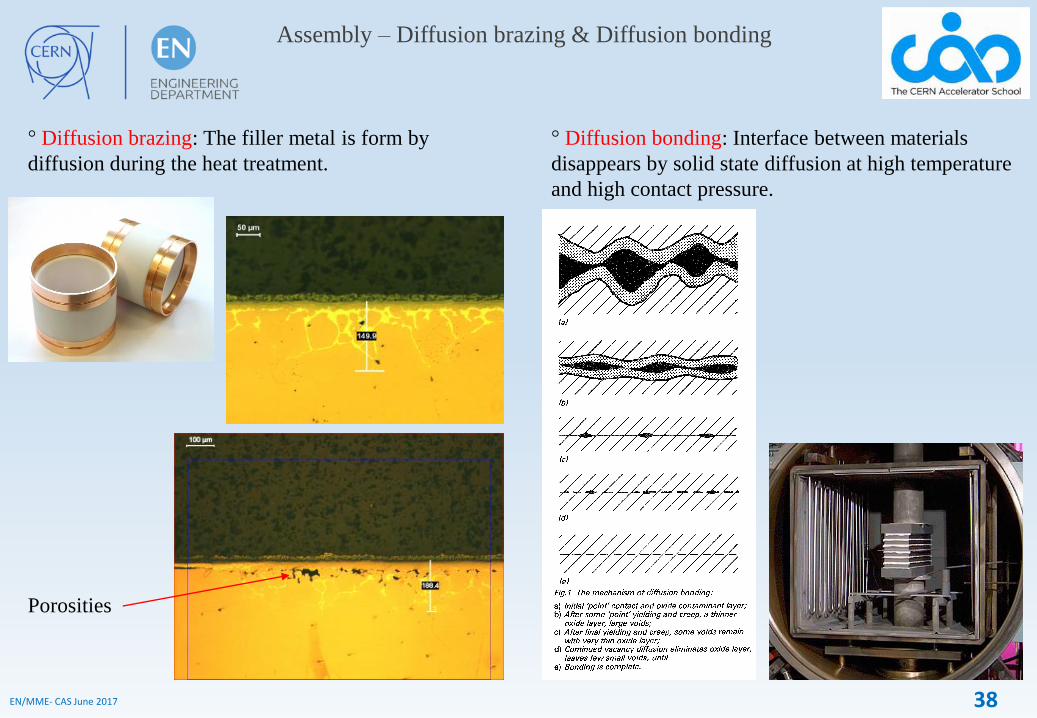
Assembly – Diffusion brazing & Diffusion bonding
° Diffusion brazing: The filler metal is form by
diffusion during the heat treatment.
Porosities
° Diffusion bonding: Interface between materials
disappears by solid state diffusion at high temperature
and high contact pressure.

39EN/MME- CAS June 2017
Assembly – Diffusion brazing & bonding
° Brazing & Partial Diffusion Bonding:
a b c
a
b
c
40EN/MME- CAS June 2017
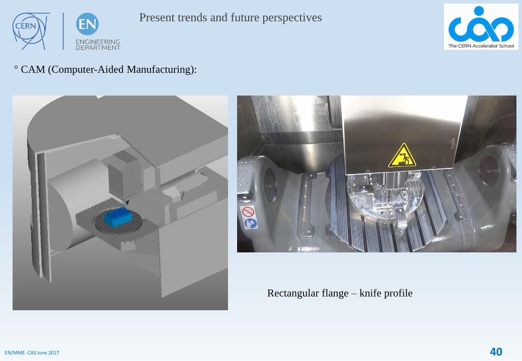
Present trends and future perspectives
° CAM (Computer-Aided Manufacturing):
Rectangular flange – knife profile

41EN/MME- CAS June 2017
Present trends and future perspectives
° Metal Additive Manufacturing:
(Contact: Romain Gérard (EN/MME))

42EN/MME- CAS June 2017
Present trends and future perspectives
° Metal Additive Manufacturing:
Beam Screen FCC
TE-VSC
Ti6Al4V Flexible ring HL LHC
TE-VSC
Ti6Al4V spring HL-LHC
TE-VSC
(Contact: Romain Gérard (EN/MME))
° Qualification for UHV is still in progress (degassing, porosities, …)

43EN/MME- CAS June 2017
Present trends and future perspectives
° Explosion welding:

44EN/MME- CAS June 2017
Present trends and future perspectives
° Magnetic Pulse Welding:

45EN/MME- CAS June 2017
Present trends and future perspectives
° High-velocity forming:
Application to Copper and Niobium for superconducting RF cavities (ex. CRAB).
° Advantages:
- Geometrical precision ( 150 µm instead of 600-800 µm
for deep drawing or spinning).
- Increased metal formability.
- Better surface finishing.
- High reproducibility.
- Reduced cost and time for forming and post-processing.
- Economic for large series production.
46EN/MME- CAS June 2017
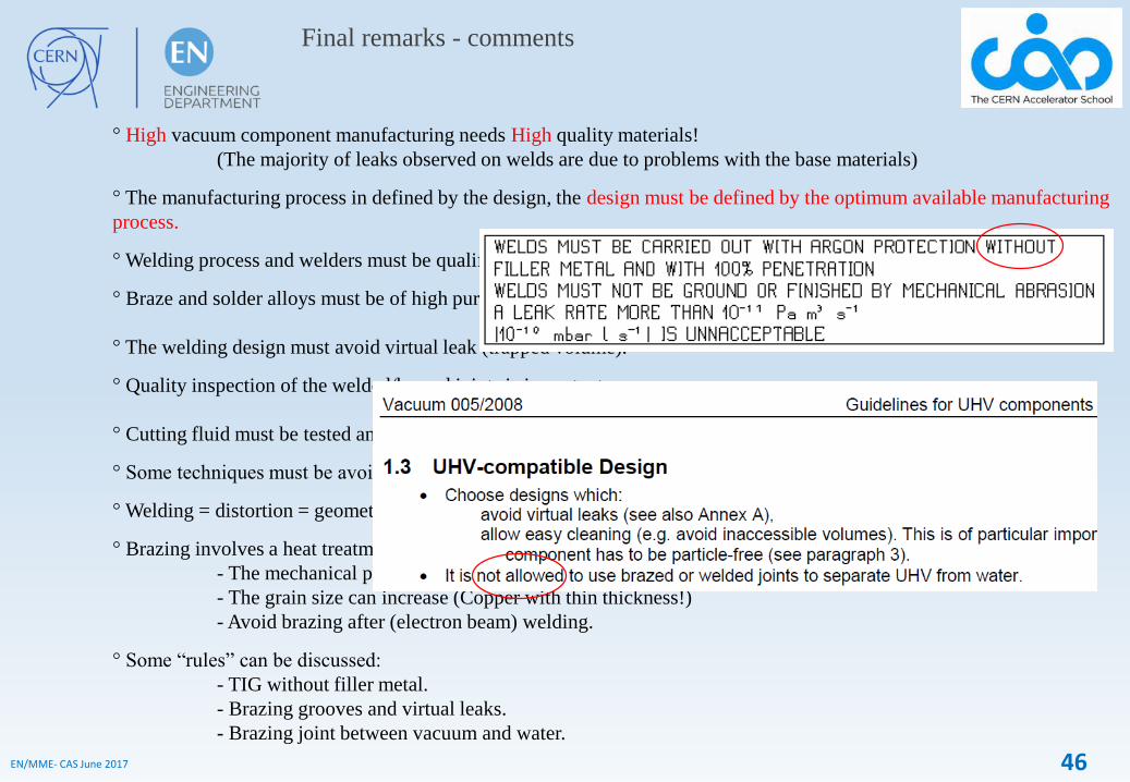
Final remarks - comments
° High vacuum component manufacturing needs High quality materials!
(The majority of leaks observed on welds are due to problems with the base materials)
° The manufacturing process in defined by the design, the design must be defined by the optimum available manufacturing
process.
° Welding process and welders must be qualified.
° Braze and solder alloys must be of high purity.
° The welding design must avoid virtual leak (trapped volume).
° Quality inspection of the welded/brazed joints is important.
° Cutting fluid must be tested and approved.
° Some techniques must be avoided / tested (air brazing/soldering, EDM, grinding, additive manufacturing,….).
° Welding = distortion = geometrical consideration. Minimum of welds!
° Brazing involves a heat treatment of the complete assembly!
- The mechanical properties are modified.
- The grain size can increase (Copper with thin thickness!)
- Avoid brazing after (electron beam) welding.
° Some “rules” can be discussed:
- TIG without filler metal.
- Brazing grooves and virtual leaks.
- Brazing joint between vacuum and water.