manually operated and pneumatically actuated valves …€¦ · safety sign in accordance with din...
TRANSCRIPT

• Operating manual• Installation instructions for partly completed machinery 0570.821-10/22 – ORIGINAL
Diaphragm ValvesManually Operated and
Pneumatically Actuated ValvesSISTO-KB / -KBS
SISTO-10 / -10S / -10MSISTO-16RGA
SISTO-16TWA / HWA / DLUSISTO-16 / -16S
SISTO-20 / -20M / -20TWCSISTO-BSISTO-C
Check ValvesRSK / RSKS
Pneumatic ActuatorsLAP Piston Actuators
LAD Diaphragm Actuators
1. Declaration of Conformity ...................................................................................................................................... 22. Safety ....................................................................................................................................................................... 3 2.1 Marking of instructions in the operating manual / installation instructions for partly completed machinery ... 3 2.2 Non-compliance with safety instructions ........................................................................................................ 3 2.3 Safety awareness .......................................................................................................................................... 3 2.4 Safety information for the operator/user ........................................................................................................ 3 2.5 Safety information for maintenance, inspection and installation work ........................................................... 3 2.6 Unauthorised modification and manufacture of spare parts .......................................................................... 3 2.7 Unauthorised modes of operation .................................................................................................................. 33. General information ................................................................................................................................................ 34. Transport and storage ............................................................................................................................................ 4 4.1 Corrosion protection............................................................................................................... ....................... 4 4.2 Transport ........................................................................................................................................................ 4 4.3 Storage .......................................................................................................................................................... 45. Description of the valves and actuators ............................................................................................................... 4 5.1 Marking .......................................................................................................................................................... 4 5.2 Drawings/documentation ............................................................................................................................... 5 5.3 List of components……………………………………………………………………………………………… ....... 9 5.4 Function ........................................................................................................................................................116. Installation ............................................................................................................................................................. 12 6.1 General ........................................................................................................................................................ 12 6.2 Installation position ...................................................................................................................................... 12 6.3 Installation instructions ................................................................................................................................ 12 6.4 Valves with actuator and pneumatic actuators on valves from other manufacturers ................................... 13 6.5 Insulation ..................................................................................................................................................... 137. Operation / Commissioning / Start-up / Shutdown ............................................................................................ 13 7.1 Operation / Commissioning / Start-up .......................................................................................................... 13 7.2 Shutdown ..................................................................................................................................................... 158. Servicing / Maintenance ....................................................................................................................................... 15 8.1 Safety instructions ....................................................................................................................................... 15 8.2 Maintenance ................................................................................................................................................ 16 8.3 Replacing the diaphragm ............................................................................................................................. 19 8.4 Replacing the valve disc .............................................................................................................................. 19 8.5 Valve reassembly ......................................................................................................................................... 199. Trouble-shooting ................................................................................................................................................... 19 9.1 General ........................................................................................................................................................ 19 9.2 Faults / Remedies ........................................................................................................................................ 1910. Tightening torques ................................................................................................................................................ 2011. Supplementary information to the operating manual with a view to Directive 94/9/EC (ATEX100) .............. 23


2. Safety
This operating manual / These installation instructions for partly completed machinery contain important information which must be observed during installation, operation and maintenance.
Not only must the general safety instructions laid down in this chap-ter on ”Safety” be complied with, but also the safety instructions outlined under specific headings.
2.1 Marking of instructions in the operating ma nual/installation instructions for partly completed machinery
The safety instructions contained in the operating manual/installa-tion instructions for partly completed machinery whose non-obser-vance might jeopardise the safety of persons, property and the envi-ronment are specially marked with the general hazard sign, namely
safety sign in accordance with DIN 4844 - W 9.The electrical danger warning symbol is
safety sign in accordance with DIN 4844 - W 8.
Safety instructions whose non-observance could result in damage to the valve or the pneumatic actuator and their functions have been marked with the word
CAUTION
Instructions attached directly to the valve or the pneumatic actuator (e.g. nominal pressure) must always be complied with and be kept in a perfectly legible condition at all times.
2.2 Non-compliance with safety instructions
Non-compliance with safety instructions can jeopardize the safety of personnel, the environment and the valve or the pneumatic actuator itself. Non-compliance with these safety instructions will also lead to forfeiture of any and all rights to claims for damages.
Non-compliance can, for example, have the following conse-quences:
- Failure of important valve or pneumatic actuator / system functions,- Failure of prescribed maintenance and servicing practices,- Hazard to persons by electrical, mechanical and chemical effects,- Hazard to the environment due to leakage of hazardous substances.
2.3 Safety awareness
It is imperative to comply with the safety instructions contained in the operating manual/installation instructions for partly completed machinery, the relevant national health and safety regulations and the operator‘s own internal work, operation and safety regulations.
2.4 Safety information for the operator/user
The valves are intended for use in areas which cannot be ac-cessed by unauthorised persons. Operation of the valves in areas which can be accessed by unauthorised persons is only permitted if appropriate protective devices are fitted at the site. This is the responsibility of the integrator or operator.
3
Any hot or cold valve components (e. g. body components or hand-wheel) that could pose a hazard must be equipped with a guard by the operator.
Guards which are fitted to prevent accidental contact with moving parts (e.g. coupling) must not be removed whilst the unit is opera-ting.
Electrical hazards must be eliminated. (For details please refer to VDE regulations and the safety regulations laid down by the local energy supply companies, for instance).
The operator has to ensure that the guards for live components are regularly checked for any damage. The valve must never be opera-ted without appropriate protection.
Standard SISTO diaphragm valves are designed in such a way that any rupture of the diaphragm will be indicated by fluid handled escaping from a leakage indication hole in the valve bonnet or from the stem protection below the handwheel. This must be taken into account when planning the system.
Design variants with re-pluggable leakage indication hole in fully sealed valves can be agreed with the manufacturer.
2.5 Safety information for maintenance, inspection and installation work
The operator is responsible for ensuring that all maintenance, inspection and installation work be performed by skilled and trained personnel.
Work on the valve must only be carried out after valve pressure has been released and the valve has been allowed to cool down and drained completely. The temperature of the fluid in all the valve‘s chambers must be lower than the fluid‘s vaporisation temperature.
Work on valves or pneumatic actuators must only be carried out during standstill. The shutdown procedure described in the opera-ting manual / installation instructions for partly completed machinery must be adhered to without fail.
As soon as the work is complete, all safety-relevant and protective equipment must be re-installed and/or re-activated.
Please observe all instructions set out in Section 7 „Commissioning/ Start-up“ before returning the equipment to service.
2.6 Unauthorised modification and manufacture of spare parts
Modifications or alterations of the valve or pneumatic actuator are only permitted after consultation with the manufacturer. Original spare parts and accessories authorised by the manufacturer ensure safety. The use of other parts can invalidate any liability of the ma-nufacturer for resulting damage.
2.7 Unauthorised modes of operation
The warranty relating to the operating reliability and safety of the valve and the pneumatic actuator is only valid if the equipment is used in accordance with its intended use as described in Section 3, General information, of the operating manual / installation instruc-tions for partly completed machinery. The limits stated in the techni-cal literature must not be exceeded under any circumstances.
3. General informationThis operating manual / these installation instructions for partly completed machinery apply to all diaphragm valves, pneumatic actuators and check valves of SISTO Armaturen S.A. as described in Section 5, unless reference is made to other operating manuals in individual cases.
Only correct installation, maintenance or repair will ensure smooth operation of the valves and the pneumatic actuators.
The manufacturer shall not accept any liability for the valves and the pneumatic actuators if this operating manual / these installation instructions for partly completed machinery are not complied with.

4.1 Corrosion protection
As a standard, valves and pneumatic actuators made of non-corro-sion-resistant materials are coated with a primer offering adequate corrosion protection under ambient conditions normally encountered in buildings.If the equipment is intended for use in a corrosion-inducing at-mosphere, the user must apply a protective coating on site.
All valves with PTFE, TFM or PFA lining are corrosion-protected to category C2, durability „L“, in accordance with DIN EN ISO 12944.
4.2 TransportSuitable precautions shall be taken to prevent damage during trans-port.
Ensure sufficient stability. Use transporting and moving equipment which complies with the standards.
CAUTION The valves must never be suspended by the handwheel or by the actuator, if any.
Valves with actuators shall be transported by means of ropes at-tached to the line connection ports, taking into account the centre of gravity.
Use any lifting lugs provided.
For the valve or pneumatic actuator weights refer to the relevant manufacturer documentation (type series booklet - > Section 5.2.).
After delivery and prior to installation, check the valve or pneumatic actuator for potential damage acquired in transit.
4.3 Storage
Storage/temporary storage of the valves or pneumatic actuators must ensure that even after a prolonged period of storage the function of the valve or pneumatic actuator will not be impaired. The following requirements must be met:
- Storage is performed with the valve in the closed position (to protect the seating surfaces against damage),
- Measures are taken to protect the equipment against dirt, humidi-ty, frost and corrosion (e.g. by using foils or caps; indoor storage).
Ensure sufficient stability. Use transporting and moving equipmentwhich complies with the standards.
5. Description of the valves and pneumatic actuators
5.1 Marking5.1.1 Marking of the valvesThe valves are marked in accordance with Pressure Equipment Directive:
- Manufacturer- Year of construction (valves for industrial and sterile applications)- Type or order number- DN- PN or max. permissible pressure/temperature- Material
The CE marking on the valve indicates that the valve is in conformity with the European Pressure Equipment Directive (not on SISTO-16TWA, SISTO-16RGA, SISTO-20M and SISTO-20TWC).
5.1.2 Marking of the pneumatic actuators
The name plate indicates the following information:
- Type series designation- Actuator size, spring code, stroke- Pmax (max. control pressure), date of manufacture- Ident. number
Spring-loaded actuators are additionally marked with a sign reading „WARNING: Loaded spring, do not disassemble!“.
As regards the design, production and inspection, valves manuf-actured by SISTO Armaturen S.A. are subject to a QA system in accordance with DIN EN ISO 9001 as well as, up to 19.07.2016, the European Pressure Equipment Directive 97/23/EC, from 19.07.2016 onwards the European Pressure Equipment Directive 2014/68/EU and, if applicable, the Machinery Directive 2006/42/EC. Compliance with these requirements, however, is based on normal, static loading, e.g.
- Flow velocities typical of the fluid handled- Typical temperature gradients
Valves manufactured by SISTO Armaturen S.A. are not designed for use in systems handling unstable fluids.
Other than normal loads and operating conditions (temperature, pressure, special corrosive, chemical or abrasive influences, etc.) must be specified fully and clearly in the purchase order, so that the valve manufacturer can prepare and suggest suitable measures. Such measures may influence
- Material selection- Wall thickness- Variants
CAUTION The valves and pneumatic actuators must not be operated outside the permissible operating range. The application li-mits are indicated on the name plate or in the applicable type series booklet. The pressure/temperature ratings, in particular, must not be exceeded. Operation outside the above-mentioned conditions will result in overloads the valves and pneumatic actuators cannot withstand.
Non-observance of this warning may cause personal injury and damage to property, for example:
- Injuries resulting from fluid leakage (cold/hot, toxic, under pres-sure …)
- Impairment of the valve/pneumatic actuator’s function or their destruction.
The descriptions and instructions set forth in the operating manual/installation instructions for partly completed machinery refer to the standard models but are also applicable to variants.
For valves equipped with actuators from other manufacturers, the operating manual of the actuator must be adhered to without fail.
The operating manual/installation instructions for partly completed machinery do not take into account- Any eventualities and events which might occur during installati-
on, operation and maintenance,- Local regulations; the operator must ensure that such regulati-
ons are strictly observed by all, including the personnel called in for installation.
CAUTION Valves or pneumatic actuators must only be opera-ted by skilled personnel.
Incorrect operation of a valve or pneumatic actuator may have adverse effects on the entire system, for example:
- Leakage of the fluid handled- System/machine brought to a standstill- Impairment / reduction / increase of the system’s / machine’s
function / effect.
For any queries you may have or in the case of damage, please contact the manufacturer.
For any queries and repeat orders, in particular for purchasing spa-re parts, please specify the type series and/or variant details, the order number, as well as the year of construction, if possible.
The technical data (operating data) of the valves or pneumatic ac-tuators are specified in the technical literature (type series booklet, valve characteristic, chemical resistance chart, etc.) of the respecti-ve valve or pneumatic actuator (cf. Section 5).
CAUTION The operating manual/installation instructions for partly completed machinery must be kept for the entire life cycle of the equipment.
When assembling components from various manufactures, the operating manuals of the individual components must also be complied with.
4. Transport and storageThe valves and pneumatic actuators are ready for operation upon delivery. The connection ports are closed with suitable material (caps, plugs, covers).
4

200915553951
100
443
926.1554.2961621.2
550.2550.1165901.1902.1/920.1
621.1
5
SISTO-10/-10S SISTO-10M
SISTO-KB/-KBSDN 15-40 Design
SISTO-KB/-KBSDN 125-200 Design
SISTO-16RGA
200165932.1550.6550.2443100
926.1554.2961621.2621.1553901.1
531.1550.1
920.1160.4566.1932.2
544.1902.1920.2
580.1940.1636.1314.1531.2
SISTO-KB/-KBSDN 50-100 Design
621.2961
621.1200165553
901.1902.1/920.1
100
926.1554.2
550.2550.1
915
443
SISTO-16/SISTO-16SSISTO-16TWA/HWA/DLUSISTO-20/ SISTO-20TWC
961926.1554.2
200550.2550.1
165901.1
100
621.2621.1553915951443500
SISTO-20M DN 25-50
550.1
100443
553
165200621.1
961
926.1
951
550.5
554.1
550.2
621.2
915901.1
100443553
901.1165200961926.1
554.1
SISTO-20M DN 10-20
926.1550.5961621.2621.1200165553915951901.1554.1443100
550.2550.1
5.2 Drawings / Documentation
The sectional drawings below provide examples of the general design/configuration of the valves and pneumatic actuators. For illustrations relating to specific type series and further information please refer to the respective type series booklets.
5.2.1 Diaphragm valves with handwheel for industry and building services
Type series DN PN Material Type series booklet No. *)SISTO-KB 015-200 10 see Type series booklet 8651.1SISTO-KBS 015-200 10 see Type series booklet 8651.101SISTO-10 015-300 10 see Type series booklet 8641.1 SISTO-10S 015-200 10 see Type series booklet 8641.101SISTO-10M Rp ½“-3“ 10 see Type series booklet 8641.102SISTO-16TWA / HWA / DLU 015-200 16 see Type series booklet 8635.33SISTO-16 015-200 16 see Type series booklet 8635.1SISTO-16S 015-200 16 see Type series booklet 8635.101SISTO-20 015-200 16 see Type series booklet 8643.1SISTO-20M 010-050 16 see Type series booklet 8638.12 Rp 3/8“ - 2“ SISTO-16RGA 015-080 16 see Type series booklet 8638.1 Rp 1/2“-3“SISTO-20TWC 015-200 16 see Type series booklet 8638.120
*) Available for download at www.sisto.lu
Sectional drawings

5.2.3. Diaphragm valves with pneumatic piston actuator for industry and building services, or pneumatic piston actuator without valve
Type series DN PN Material Type series booklet No. *)SISTO-KB/-KBS 015-200 10 see Type series booklet 8651.1 / 8651.101SISTO-10/-10S 015-300 10 see Type series booklet 8641.1 / 8641.101SISTO-16/-16S/-20 015-200 16 see Type series booklet 8635.1 / 8635.101 / 8643.1SISTO-LAP see Type series booklet 9210.1
901.5901.3920.7
412.5141.1
310.1400.1
920.3902.2
920.10
160.2
400543.1595.1412.4
176.1410.1
932.3209920.8558.1
901.3
543.1
595.1
160.2914.1547.1209.1141.1950.1
310.1176.1410.1932.3209.1920.8
412.5412.4
400.1920.3902.2
920.10558.1
6
SISTO-LAD-OF
SISTO-LAD-AZ
SISTO-LAP-AZ
SISTO-LAP-SF
412.7412.6443.4
412.7412.6
443.4
547.5950.1
209
412.7
901.2920.911
412.1
151.2
840
443.4
550
151.1
165
200.3
595.2593766.1
595.2
593766.1
901.5160.2
400.1
412.5
209.1950.1310.1412.4410.1932.3
920.8
840
920.9
200412.13915
920.12
595.1
543.1
141.1
176.1920.3902.2
920.10
621.4
166.1553
901.1
100
901.3
443
558.1
5.2.2. Diaphragm valves with pneumatic diaphragm actuator for industry and building services or pneumatic diaphragm actuator without valve
Type series DN PN Material Type series booklet No. *)SISTO-KB/-KBS 015-100 10 see Type series booklet 8651.1 / 8651.101SISTO-10/-10S 015-125 10 see Type series booklet 8641.1 / 8641.101SISTO-16/-16S/-20 015-125 16 see Type series booklet 8635.1 / 8635.101 / 8643.1Sectional drawings
SISTO-diaphragm valve withmounted SISTO-LAD-SF
Sectional drawings
SISTO diaphragm valve withmounted SISTO-LAP-OF
*) Available for download at www.sisto.lu
Piston 300 Piston 500

443
554.4 951
547.5
950.1
209
901.2920.911
200.3
151.2
443.2554.4
151.1
412.1165
100
553915
901.1/902+920.1
685.1
920.3
920.5 920.18
412.7913.1
7
SISTO-B DN 06-10 SISTO-B DN 32-50 SISTO-B DN 15-25
160.5
514.1
901.1920.1554.1553443100
961
412.8
200
165
961
544.1
825.2
165915562.1
100
200
443
901.1412.2
932.2160.5
412.8
553554.1
544.1
825.2412.8
915412.2
553554.1
100
961562.2
550.3550.2200165562.1
901.1443
SISTO-B DN 65-100
961
621.2621.1
200553165
901.1/902.1+920.1
554.1100
920.2554.2
550.3550.1915951443
160.3
595.1
547.1 621
950.1
920.
412.553901.1
554209.1
100
554.1165
176.2412.443
SISTO-B DN 100 - ML 226 Variante Edelstahl
920.2
904
5
200.1553
951
310.
902 +920.
100
961412.1
940550.5314840514.
92554
SISTO-B DN 100
547.1160.3209.2950.1
920.7176.2920.6932.1915412.2901.1554.1165
484.1920.17
554.3
595.1
412.1
412.2
562.1553
100
5.2.4. Diaphragm valves with handwheel or pneumatic actuator, or pneumatic actuator for sterile processes
Type series DN PN Material Type series booklet No. *)SISTO-B 006-100 10 see Type series booklet 8646.1
Sectional drawings
SISTO-B with handwheel
SISTO-B with mounted LAP-SF
SISTO-B LAP-SF DN 06-10 Compressed air 5-7 bar
SISTO-B LAP-SF DN 15-50 Compressed air 5-7 bar
SISTO-B LAD-SF DN 65-100 Compressed air 4-6 bar
*) Available for download at www.sisto.lu

8
MD 30 MD 40 MD 65
160.5544.1
412.14165901.1
915443
961
200
825.2
553100
160.5932.2
961
165562.1915901.1951443
544.1
825.2412.14
200
554.1
553100
412.2
160.5514.1
901.1553443100
961412.8
200
165915
554.1
926.1
554.2
550.2550.1915951443
961
621.2
200
553
165901.1554.1
100
926.1
554.2
412.1
550.2
550.1
915
951443
961
621.2
200
553
165901.1554.1
100
621.5
961940.1
544.1314.1
200
562.1
901.1951
443
580.2
160.9
132.2310.5
412.1553
915
165100
621.5
961940.1544.1314.1
200
562.1
901.1951
443
580.2
160.9
132.2
310.5
412.1
553
915
165
100
MD 92 MD 115 MD 168 MD 202
554.1
580.1
554.1
554.1
562.1
932.2
950.1
554.3
920.6
412.3553901.1554.1165
209.2
160.3547.1
595.1209.1
176.2412.1
443100
950.1
412.3
176.2
932.4
553
901.1
165443
547.1160.3
209.2
595.1
412.1209.1562.1412.2
100
578.1 950.1 160.3 209.2 950.2
920.7 176.2 920.6
932.4 901.1 554.1
165 412.3
915
412.1
547.1
920.17554.3595.1
209.1562.1
553443100
547.1160.3
950.1
209.2
412.1176.2
951443100
209.1
578.1
920.17
595.1
165
901.1554.1
554.5554.3
412.3
553
915
950.1
595.1
165 951 443
412.1
160.3
578.1
100554.1901.1
553
825.3547.1
209.2 554.5
554.3
209.1
554.4
915
920.17
920.6
412.3
412.12
59-18.1
580.2825.3
412.15160.2
412.12
88-5.1950.1950.2310.4
209.2412.5310.3920.6412.12209.1562.1553951443
412.16578.1
920.17
412.16595.2
593
766.1
176.1
412.1165
412.2
915100
412.3
59-18.1580.2
825.3412.15
160.2
412.12
88-5.1950.1
950.2
310.4
209.2
412.5310.3
920.6
412.12209.1562.1553951443
412.16578.1
920.17412.16
595.2
593766.1
176.1
412.1165
412.2
915100
412.3
901.3
MD 30 MD 40 MD 65
MD 92 MD 115 MD 168 MD 202
920.6
141.1
141.1
176.1
920.7
915
554.1
915 951
412.3
920.6
554.1554.1
5.2.4. Diaphragm valves with handwheel or pneumatic actuator, or pneumatic actuator for sterile processes
Type series DN PN Material Type series booklet No. *)SISTO-C 006-100 16 see Type series booklet 8644.1Sectional drawings
SISTO-C with handwheel
SISTO-C with mounted LAP-SF
*) Available for download at www.sisto.lu

Part No. Description
100 Body101 Upper body102 Lower body132.1 Intermediate piece132.2 Intermediate piece141.1 Cylinder141.2 Cylinder151.1 Lower housing section151.2 Upper housing section151.3 Lower housing section160.1 Cover160.2 Top end cap160.3 Cover160.4 Handwheel cover160.5 Handwheel cover160.6 Bearing cover160.7 Cover160.8 Bearing cover 160.9 Bearing cover165 Bonnet166.1 Yoke168.1 Yoke168.2 Yoke176.1 Bottom end cap176.2 Bottom176.3 Bottom188 Fixing plate188.1 Bracket200 Stem200.1 Stem200.2 Stem200.3 Stem201 Actuator stem202 Sliding stem209 Piston rod209.1 Lower piston rod209.2 Upper piston rod209.3 Upper piston rod209.4 Upper Piston rod310.1* Plain bearing310.3 Plain bearing310.4 Plain bearing310.5 Plain bearing314.1 Thrust bearing314.2 Thrust bearing314.3 Thrust bearing400.1* Gasket410.1* Seal/ wiper set411.1 Joint ring411.2* Joint ring411.3 Joint ring411.4 Joint ring412.1* O-ring
* Recommended spare parts
Part No. Description
412.2 O-ring412.3 O-ring412.4* O-ring412.5 O-ring412.6* O-ring412.7* O-ring412.8 O-ring412.9 O-ring412.10 O-ring412.11 O-ring412.12 O-ring412.13 O-ring412.14 O-ring412.15 O-ring412.16 O-ring443* Diaphragm443.1* Backing diaphragm443.2* Diaphragm443.3* Diffusion-proof foil443.4* Actuator diaphragm484.1 Spring plate484.2 Spring plate485.1 Stem coupling485.2 Stem coupling500 Ring511 Backing ring514.1 Threaded disc527.1 Locating sleeve528.1 Protection sleeve531.1 Locking sleeve531.2 Locking sleeve543.1 Spacer bush544.1 Threaded bush544.2 Threaded bush544.3 Threaded bush547.1 Guide bush547.2 Guide bush547.3 Guide bush547.4 Guide bush547.5 Guide bush547.6 Guide bush547.7 Guide bush547.8 Guide bush550 Diaphragm plate550.1 Bearing disc550.2 PTFE-disc550.3 Bearing disc550.4 PTFE-ring550.5 Identification disc550.6 Segmental disc 553 Compressor554.1 Washer554.2 Washer
100 411.2 746 160.1 901.1
9
RSK/RSKS
5.2.5. Check valves for industry and building services
Type series DN PN Material Type series booklet No. *)
RSK/RSKS 025-300 16 see Type series booklet 8675.1
Sectional drawings
5.3 List of components
*) Available for download at www.sisto.lu

Part-No. Description
900.5 Screw900.6 Screw901.1 Hexagon head bolt901.2 Hexagon head bolt901.3 Hexagon head bolt901.4 Hexagon head bolt901.5 Hexagon head bolt901.6 Hexagon head bolt901.7 Hexagon head bolt902.1 Stud902.2 Stud902.3 Stud902.4 Stud903.1 Screwed plug904.2 Grub screw904.3 Grub screw904.4 Grub screw911 Compressed air port913.1 Vent plug914.1 Hexagon socket head cap screw915 Floating nut920.1 Nut920.2 Nut920.3 Nut920.5 Nut920.6 Nut920.7 Nut920.8 Nut920.9 Nut920.10 Nut920.11 Nut920.12 Nut920.13 Nut920.14 Nut920.15 Nut920.16 Nut920.17 Nut920.18 Nut920.19 Nut925 Square nut926.1 Prevailing torque nut926.2 Prevailing torque nut932.1 Circlip932.2 Circlip932.3 Circlip933.1 Split pin940.1 Parallel key950.1 Spring950.2 Spring950.3 Spring951 Support spiral961 Handwheel970.1 Type plate970.2 Danger sign970.3 Stainless steel plate
Part-No. Description
554.3 Washer554.4 Washer554.5 Washer 557.1 Guide disc558.1 Safety washer558.2 Safety washer558.3 Safety washer558.4 Safety washer558.5 Safety washer558.6 Safety washer558.7 Safety washer558.8 Safety washer562.1 Parallel pin562.2 Parallel pin566.1 Grooved pin566.2 Grooved pin572.1 Contact piece578.1 Spring guide579.1 Anti-twist protection580.1 Cap580.2 Cap59-18.1 Hook593* Piston seal595.1* Piston assembly595.2 Piston595.3 Piston621.1 Position indicator, lower part621.2 Position indicator, upper part621.3 Position indicator621.4 Position indicator621.5 Position indicator636.1 Lubricating nipple685.1 Cover729.1 Intermediate flange734.1 Cable gland740 Valve746* Valve disc766.1 Guide band767.1 Rod guide809.1 LAP809.2 LAD809.3 E-Drive812.1 Plug81-29.1 Terminal814.1 Limit switch814.2 Limit switch825.1 Adapter825.2 Adapter825.3 Adapter840 Coupling88-5.1 Silencer900.1 Screw900.2 Screw900.3 Screw900.4 Screw
* Recommended spare parts
10

The functional unit of the pneumatic piston actuator without valve consists of the bottom end cap (176.1), cylinder (141.1), top end cap (160.2), piston (595.1/595.2), spring (950), piston rod (209.1) and piston rod (209.2).
5.4.4 Diaphragm valves with handwheel or pneumatic actua- tor for sterile processes
Diaphragm valves with pneumatic diaphragm actuator or pneumatic diaphragm actuators without valves are available in spring-to-close (SF = fail-close), spring-to-open (OF = fail-open) and double-acting (AZ) design.
The valves/actuators are automatically taken to their fail-safe positions as soon as the control air is intentionally or unintentio-nally released. The visible moving parts of the valve (both manual and automatic actuation) also serve as position indicators for the valve.
Diaphragm valves for sterile processes are either of the SISTO-C or SISTO-B type.The valves consist of the pressure-retaining parts, i.e. body (100) and bonnet (165), and the functional unit. The body (100) and actuator or bonnet (165) are connected by hexagon head bolts (901).
The functional unit of diaphragm valves with handwheel consists of the bonnet (165), handwheel (961), stem (200), compressor (553) and the diaphragm (443).
The functional unit of SISTO-C diaphragm valves with pneumatic actuator consists of a pneumatic piston actuator (SF = fail-close, OF = fail-open, AZ = double-acting). The piston actuator (165) consists of the bonnet with a G 1/8“ control air port (DIN ISO 228-1), cover (160), compressor (553), piston rod (209), position indicator (621), piston (595) and the diaphragm (443).
The functional unit of SISTO-B diaphragm valves with pneumatic actuator consists of the pneumatic piston actuator (SF, OF+AZ). The piston actuator (165) consists of the bonnet with a G 1/8“ control air port (DIN ISO 228-1), compressor (553), piston rod (209), bottom end cap (176.1), cover (160), piston (595), spring (950.), spring plate (484) and the diaphragm (443). Manually actuated diaphragm valves of the series SISTO-C in the upper part size MD30 and SISTO-B in the upper part size ML32 are equipped with an integrated, adjustable end position limitation in the direction of closing. At the factory, this end position limitation in the shut position is adjusted with the excess length X of the pressure piece (443) in relation to the hood (165). This adjustment ensures the sealing function in the shut position and, at the same time, imple-ments overload protection for the diaphragms (443).
5.4 Function
5.4.1 Diaphragm valve with handwheel for industry and building services
The valves consist of the pressure-retaining parts, i.e. body (100) and bonnet (165), and the functional unit.The body (100) and the upper valve section or bonnet (165) are connected by hexagon head bolts (901.1) or studs (902.1) and nuts (920.1).
The functional unit consists of the bonnet (165), handwheel (961), stem (200), compressor (553) with square nut (925) or floating nut (915) and the diaphragm (443).
5.4.2 Diaphragm valves with pneumatic diaphragm actua- tor for industry and building services, or pneumatic diaphragm actuators without valves
Diaphragm valves with pneumatic diaphragm actuator or pneu-matic diaphragm actuators without valves are available in spring-to-close (SF = fail-close), spring-to-open (OF = fail-open) and double-acting (AZ) design.
The valves/actuators are automatically taken to their fail-safe positions as soon as the control air is intentio-nally or unintentionally released. The visible moving parts of the valve (both manual and automatic actuation) also serve as position indicators for the valve.
The valves consist of the pressure-retaining parts, i.e. body (100) and bonnet (165), and the functional unit.The body (100) and actuator or bonnet (165) are connected by hexagon head bolts (901) or studs (902) and nuts (920).
The functional unit of the pneumatic diaphragm actuator without valve consists of the lower actuator housing section with interface (151.1), upper actuator housing section (151.2), actuator dia-phragm (443.4), diaphragm plate (550), spring (950), stem (200.3) and the sliding stem (202).
The functional unit of the diaphragm actuator consists of the bonnet (165), actuator housing sections (151.1/151.2), actuator diaphragm (443.4) with diaphragm plate (550), spring (950) (for OF and SF designs), stem (200.3), sliding stem (202), compressor (553) with floating nut (915) and the diaphragm (443).
5.4.3 Diaphragm valves with pneumatic piston actuator for industry and building services
Diaphragm valves with pneumatic piston actuator or pneumatic piston actuators without valves are available in spring-to-close (SF = fail-close), spring-to-open (OF = fail-open) and double-acting (AZ) design.
The valves/actuators are automatically taken to their fail-safe positions as soon as the control air is intentio-nally or unintentionally released. The visible moving parts of the valve (both manual and automatic actuation) also serve as position indicators for the valve.
Diaphragm valves with pneumatic piston actuators are available in spring-to-close (SF), spring-to-open (OF) and double-acting (AZ) design.
The valves consist of the pressure-retaining parts, i.e. body (100) and bonnet (165) with yoke (166.1), and the functional unit. The body (100) and the actuator or bonnet (165) with yoke (166.1) are connected by bolts (901.1) or studs (902.1) and nuts (920.1).
The functional unit of the piston actuator consists of the bonnet (165) with yoke (166.1), bottom end cap (176.1), top end cap (160.2), cylinder (141.1), piston (595.1/595.2), spring (950), for OF and SF designs, piston rod (209.1), compressor (553) with floating nut (915) and the diaphragm (443).
11
961
160.5
443165
200
514.1
412.8
x = 2 mm
SISTO-C MD30 description
x = 1,7 mm
SISTO-B ML32 description

6.2 Installation position
The valve bodies are marked with an arrow indicating flow direction, if necessary. The valves must be installed such that the flow direction of the fluid corresponds to the direction shown by the arrow on the valve. If no directional arrow is indicated on the valve, the valve can be installed in any position.
6.2.1 Diaphragm valves
Diaphragm valves can be installed in any position. However, the best installation position is with the stem pointing vertically upwards.
6.2.2 Check valves
RSK/RSKS swing check valves must always be installed such that the flow direction of the fluid corresponds to the direction shown by the arrow on the cover (160).
6.2.3 Special designs
For positioning and installing special valve designs please contact the consultant, construction company or operator.
6.3 Installation instructions
6.3.1 Flanged valves
The mating flange faces must be clean and undamaged.
The gaskets on the mating faces must be properly cen-tered. Use only fasteners and sealing elements made of approved materials. Valves with PTFE/TFM/PFA lining must not be used in combination with metallic seals. Valves with soft rubber lining or PTFE/TFM/PFA lining do not require flange gaskets due to the pro-perties of the materials used, provided that the mating flanges of the piping comply with the same technical codes as the valves. Always use all flange bolt holes provided when connecting valve and pipe flanges.
Use suitable tools to tighten the bolts evenly and crosswise to the torques stipulated for the flanged connection in accordance with the gasket manufacturer‘s instructions.
6.3.2 Welding instructions
Responsibility for welding the valves into the piping and for any heat treatment required lies with the commissioned company or the plant operator.
CAUTION When welding valves with butt or socket weld ends into the piping or when performing welding jobs on a pipeline after the valves have been installed (pipeline installation) make sure that no contamination enters the valve body, to prevent damage to linings or diaphragms.
CAUTION When welding the valve into the pipeline, take special precautions e.g. welding in several steps and at high welding speed, so that the temperature rise in the middle of the valve body does not exceed the max. permissible operating temperature. The upper valve section including diaphragm must be removed prior to welding the valve body into the piping.
CAUTION To prevent scorching, welding cables must not be attached to valves whose functional valve elements or valve surface have to meet specific roughness requirements.
For changing this factory setting, the hand wheel (961) together with the cover (160.5) must be removed upwards from the spindle. After adjusting the desired end position of the valves by actuating the spindle (200), the plate with threaded holes (514.1) must be adjusted by clockwise rotation until it is installed on the hood (165). By re-attaching the hand wheel using the plate with threaded holes (514.1) equipped with an O-ring (412.8) and the spindle (200), this adjustment is secured. After fitting the cover (160.5), the hand wheel (961) is secured on the spindle (200).
5.4.5 Check valves for industry and building services
Swing check valves for industry and building services
RSK/RSKS swing check valves consist of the body (100), cover (160), joint ring (411) and the valve disc (746). The cover (160) and body (100) are connected by hexagon head bolts (901). The upper end of the valve disc (746) is clamped tightly between the cover (160) and the body (100), allowing the lower end to move freely in the swing check valve‘s flow path. This ensures that the valve disc (746) is pressed against the seat in one direction, shutting off the flow.
6. Installation6.1 General
Responsibility for positioning and installing the valves or the pneu-matic actuators always lies with the engineering company, construc-tion company or operator/user.
Planning and installation errors may impair the reliable function of the valves or pneumatic actuators and pose a substantial safety hazard. Compliance with the following requirements is of particular importance:
CAUTION The piping shall be laid in such a way as to prevent detrimental thrust and torsional forces from being transmitted to the valve bodies in installed and operating condition, to avoid impair-ment of valve function and/or valve rupture.
CAUTION The caps on the connection ports shall be removed immediately prior to installation.
CAUTION The flanged ends of the flanged valves described in this manual comply with flange standard EN 1092-1 / -2, incl. finish of sealing surfaces for elastomer or fluoroelastomer gaskets. Do not paint any parts which are relevant to the function of the valve, such as moving stems and position indicator compon-ents. Do not use valve handwheels as footholds.
For safety reasons, valves and piping systems operated at high (>50 °C) or low (<0 °C) temperatures must be insulated, or a warning sign must point out the risk of personal injury involved when touching the hot or cold components
In keeping with German energy-saving regulations (EnEV) we recommend that valves handling warm fluids should be insulated to save energy. Insulating plastic-coated valves will extend the service life of the valves‘ plastic coating.
Valves and pneumatic actuators with external moving elements must be fitted with protective covers, or other suitable measures must be taken to prevent accidents.
Valves used as dead-end valves in a pipeline should be protected against unauthorised or unintentional opening, to prevent personal injury and/or damage to property and the environment.
12

7.1.3 Functional check prior to commissioning
Check the shut-off function of the installed valve prior to commissio-ning / start-up by opening and closing it several times.If required, evenly re-tighten the cover/bonnet bolting as well as the bolting at the mating flanges (see Section 10).
CAUTION Before re-tightening the bonnet/cover bolting open the valve by two full handwheel turns to prevent jamming.
7.1.4 Valves with actuator
On valves with electric or pneumatic actuators, the strokes / actuating forces must be limited.
Electrical actuators are factory-set ready for operation. They shall be wired as follows:
Valve „CLOSED“ travel-dependent, valve „OPEN“ travel-dependent.
CAUTION Changing to force-dependent limit switching may reduce the service life of the diaphragm.
The wiring diagrams are located in the terminal boxes.
For pneumatic actuators, the control pressures specified in the order shall be complied with. Non-observance may damage the actuator.
Closing and opening torques or actuating forces shall be enquired from the manufacturer, if necessary.
7.1.5 Manual override of pneumatically actuated valves by fitted emergency handwheel in the event of auxili- ary energy failure
Manual override on double-acting actuators (LAP-AZ):
Drawing (example):
If the auxiliary energy supply fails, the actuator can be operated ma-nually by means of the emergency handwheel (961) mounted on the pneumatic actuator (LAP).
On valves with socket weld ends, the insertion depth given in the applicable technical code must be complied with. A gap between the pipe end and the socket base is to prevent impermissible stres-ses in the weld.
6.4 Valves with actuator
Valves with gearboxes or actuators as well as pneumatic actuators mounted on valves from other manufacturers must be installed with the stem in the vertical position. If this condition cannot be met, adequately support the valve on site or consult the manufacturer.
Electrical connection shall be effected by suitably trained personnel only.
6.5 Insulation
If the valve is to be insulated, make sure that the insulation does not impair the function of the valve. SISTO Armaturen S.A. recom-mends to make sure that the sealing areas at the bonnet joints and at the stem passage are easily accessible and visible.
7. Operation / Commissioning / Start-up / Shutdown
(Please also refer to Section 6, Installation)
7.1 Operation / Commissioning / Start-up
7.1.1 General
Prior to commissioning / start-up compare the material, pressure and temperature data on the valves with the operating conditions of the piping to check the material’s chemical resistance and stability under load.
Surge pressures, which might occur, must not exceed the max. permissible pressure. Safety measures are required to be taken by the operator.
In new systems and particularly after repair, the complete piping system must be thoroughly flushed with the valves fully open so that particles and/or welding beads that might damage the valves are removed.
The responsibility for the media and method used for cleaning the piping system lies with the party carrying out the cleaning.
Venting the valve by undoing, e.g., the bonnet/cover bolting is dangerous and therefore not permitted. To pre-vent damage to the valve material or joint seals, the usual start-up and shutdown velocities must be adhered to.
7.1.2 Valve actuation
Viewed from above, the manually operated valves are closed by turning the handwheel in clockwise direction, and opened by tur-ning the handwheel in anti-clockwise direction. Valve variants which deviate from this rule are marked accordingly.
CAUTION Valves with handwheels must only be actuated by hand. As the valve can be damaged by applying excessive force, it the use of levers for turning the handwheel is not allowed.
Shut-off valves are normally used in such a way that they are either fully open or fully closed.
If, while opening or closing the valve, a resistance can be felt, the valve is in its final position and the operation must be stopped. Continued actuation may result in increased wear of the valve.
13
.
.
.
.
.

In normal operation, the emergency handwheel is disengaged from the pneumatic actuator. For the pneumatic actuator to be operated via the emergency handwheel in emergencies, the two systems must be connected with each other as described below.
Turn the handwheel (961) in clockwise direction to position the upper stem (200.2) incl. coupling (485.1) on the upper piston rod (209.4). Connect the coupling (485.1) and the piston rod (209.4) with the spring cotter (933.1) supplied. The actuator can now be moved to the closed position by turning the handwheel (961) clockwise and to the open position by turning the handwheel anti-clockwise.
NOTE Risk of system malfunction Automatic operation of the pneumatic actuator with the manual override engaged could result in valve damage and/or system malfunction.
NOTE Risk of system malfunctionThe spring cotter (933.1) must be removed before the actuator is returned to normal operation. Turn the handwheel (961) anti-clock-wise until the stem (200.2) has been returned to its initial position. Finally, remove the spring cotter (933.1) and insert it into the bore provided in the yoke (168.2) below the anti-rotation device fitted on the stem.
Manual override on spring-to-open actuators (LAP-OF):
Drawing (example):
If the auxiliary energy supply fails, the actuator can be manually operated in closing direction by means of the emergency hand-wheel (961) mounted on the pneumatic actuator (LAP).
In normal operation, the emergency handwheel is without function.
To operate the pneumatic actuator via the emergency handwheel in emergencies, proceed as follows:
Turn the handwheel (961) in clockwise direction. The stem (200.2) will compress the spring pack via the piston (595.2), thus closing the valve. The emergency handwheel cannot be used to actuate a mechanically blocked valve.
NOTE Risk of system malfunction Activating automatic operation of the pneumatic actuator before having returned the manual override to its initial position could result in valve damage and/or system malfunction.Valve travel would be restricted, resulting in a reduced volume flow through the valve.
NOTE Risk of system malfunction Before reactivating normal operation, turn the handwheel (961) anti-clockwise to return the stem (200.2) to its initial position up to the stop.
Manual override on spring-to-close actuators (LAP-SF):
Drawing (example):
If the auxiliary energy supply fails, the actuator can be manually operated in opening direction by means of the emergency hand-wheel (961) mounted on the pneumatic actuator (LAP).
In normal operation, the emergency handwheel is without function. To operate the pneumatic actuator via the emergency handwheel in emergencies, proceed as follows:
Turn the handwheel (961) in anti-clockwise direction. The threaded bush (544.3) will contract the spring pack (950.1) via the upper piston rod (209.4), thus opening the valve. The emergency hand-wheel cannot be used to close a mechanically blocked valve.
NOTE Risk of system malfunction Activating automatic operation of the pneumatic actuator before having returned the manual override to its initial position could result in valve damage and/or system malfunction.Valve travel would be restricted, preventing the valve from reaching the fully closed position and providing tight shut-off.
NOTE Risk of system malfunction Before reactivating normal operation, turn the handwheel (961) clockwise to return the threaded bush (544.3) to its initial position up to the stop.
Manual override with travel stop in closing direction on double-acting actuators (LAP-AZ):
Drawing (example):
14
209.4
595.2950.1
200.2
961
.
.
.4
..

Manual override with travel stop in opening direction on spring-to-close actuators (LAP-SF):Drawing (example):
For the emergency handwheel to be actuated, the two locked nuts (920.15) must be loosened first. Then proceed as described in the Section on „Manual override on spring-to-close actuators“.
To set the travel stop, first loosen the two nuts (920.15) and screw them to the upper limit position. The actuator must be in the „CLOSED“ position. Then turn the handwheel in closing direction until the required travel limit is reached. Now screw the two nuts (920.15) downwards up to the stop and lock firmly.
NOTE Risk of system malfunctionVibrations may result in the locked nuts working loose. The travel stop, therefore, needs to be checked regularly.
7.2 Shutdown
In the event of prolonged shutdowns, SISTO Armaturen S.A. recom-mends draining from the piping fluids which change their physical condition due to changes in concentration, polymerisation, crystalli-sation, solidification, etc. If required, flush the piping with the valves fully opened.
8. Servicing / maintenance
8.1 Safety instructions
Servicing and maintenance work must only be performed by com-petent personnel taking into account the relevant health and safety regulations.It is imperative that the below safety instructions and the general information on safety as per Section 2, Safety, be observed for all servicing and maintenance work to be performed at the valves and pneumatic actuators.
CAUTION Always use suitable spare parts and reliable, safe tools to ensure proper functioning of the valve or pneumatic actua-tor.
8.1.1 Dismantling of valves
Before removing the complete valve from the pipe, or before repair or maintenance work on the valve itself, i.e.- before undoing the flange bolting between the valve and the pipe- before removing the cover/bonnet- before removing any drain or vent plugs- before removing a bolted-on actuatorvalve pressure must be released and the valve must be allowed to cool down such that the temperature is below the fluid‘s vapori-sation temperature in all areas in contact with the fluid in order to effectively prevent any risk of scalding.
For actuating the emergency handwheel refer to the Section on „Manual override on double-acting actuators“.
To set the travel stop, loosen the nut (920.14) which locks the loca-ting sleeve (527.1) in position. The actuator must be in the „OPEN“ position. The travel stop in closing direction can now be positioned as required by turning it clockwise. Now screw the nut (920.14) down against the locating sleeve (527.1) and lock firmly.
NOTE Risk of system malfunction Vibrations may result in the locked nut working loose. The travel stop, therefore, needs to be checked regularly.
Manual override with travel stop in opening direction on spring-to-open actuators (LAP-OF):
Drawing (example):
For the emergency handwheel to be actuated, the two nuts (920.16) must be loosened and screwed to the upper limit position. Then proceed as described in the Section on „Manual override on spring-to-open actuators“.
To set the travel stop, first loosen the two nuts (920.16) and screw them to the upper limit position. The actuator must be in the „CLOSED“ position. Then turn the handwheel in closing direction until the required travel limit is reached. Now screw the two nuts (920.16) downwards up to the stop and lock firmly.
NOTE Risk of system malfunction Vibrations may result in the locked nuts working loose. The travel stop, therefore, needs to be checked regularly.
15
.
. 5

Never open a valve under pressure (danger to life).If toxic or easily inflammable fluids were handled or fluids whose residues may cause corrosion when coming into contact with atmospheric humidity,drain the valve and flush or vent it.If required, wear safety clothing and a protective mask!
Depending on the installation position, fluid residues may be left in the valve; these must be collected and properly disposed of.Prior to any transport, flush and drain the valve thoroughly. If you have any questions please contact the manufacturer.
For actuated valves, also observe the following additional instructions:
If actuators powered by an external source of energy (electric or pneumatic) need to be removed from the valves or dismantled, the energy supply must be shut down prior to starting any work and the instructions in Sections 3, 8.1.1 and the operating manual of the actuator must be observed.
Actuators with integrated spring mechanism contain pre-loaded springs. They shall only be dismantled with extreme caution, using the requisite locking devices.
If you have any questions please contact the manufacturer.
8.2 Maintenance
All valve and pneumatic actuator components have been designed to be largely maintenance-free. The materials of the sliding parts have been selected for minimum wear.
On any diaphragm valve, the diaphragm is the highest stressed component.On RSK/RSKS swing check valves, the valve disc is the highest stressed component.
The highest stressed components (diaphragm, valve disc) are not only subjected to mechanical stress but also to wear caused by the fluid handled. We recommend to regularly check these wear parts at intervals to be individually stipulated depending on service condi-tions and actuation frequency.
- To check the diaphragm, remove the upper valve section from the valve body. See Section 8.3, Replacing the diaphragm.- To check the valve disc, remove the cover from the valve body. See Section 8.4, Replacing the valve disc.
We recommend to regularly check these wear parts at intervals to be individually stipulated depending on service conditions and actuation frequency and replace them if required.
The operator/user is responsible for fixing appropriate inspection and servicing intervals as required by the service conditions of the valves and the pneumatic actuators.
The service life of the valves and pneumatic actuators can be prolonged by:
- actuating the valve (open-close) at least once or twice a year to check its function, and- lubricating the movable parts with standardised lubricants to DIN 51825 which are suitable for the application of the valve.
The safety instructions in Sections 2 and 8.1 and the notes in Sec-tion 9 shall be observed.
16
8.3 Replacing the diaphragm
8.3.1 Replacing the diaphragm of diaphragm valves with handwheel for industry and building services
Undo the hexagon head bolts (901.1) or the studs (902.1) and nuts (920.1) to remove the upper valve section. Unscrew the diaphragm (443) from the compressor (553) and the floating nut (915) by turning it anti-clockwise. When fitting the replacement diaphragm refer to the material marking on the diaphragm.
Proceed as follows to fit the new diaphragm (443):
• The contact surfaces of the diaphragm inside the body and the bonnet must be clean and dry.
• Turn the handwheel (961) in clockwise direction to take the upper valve section (165) to the closed position.
• On valves with support spiral (951) make sure to place the sup-port spiral into the bonnet and verify that the last winding of the support spiral protrudes beyond the sealing lip. The last winding of the support spiral must not end on a compressor ridge.
• Remove any protection from the fastening grub screw of the diaphragm.
• Screw in the diaphragm as far as it will go, i.e. until it rests against the compressor (553), then back it off by a maximum of 180° to ensure it is correctly aligned.
• Turn the handwheel (961) in anti-clockwise, i.e. opening, direc-tion until the diaphragm rests against the bonnet. Do not turn any further.
• On SISTO-16/20 valves, make sure that the centring boss of the diaphragm aligns with the „pocket“ in the valve body.
• Now place the bonnet (165) onto the body (100) and tighten the bonnet (165) fastening bolts by hand.
• Tighten the bonnet bolts evenly and crosswise in accordance with the tightening torques table.
The required torques are given in Section 10.
Diaphragms marked „MD 40“ and featuring a fastening button on the back of the diaphragm are buttoned into the compressor (553) by means of this button. Simultaneous pulling and turning on one side will easily remove the diaphragm (443) from the compressor.
When fitting the bonnet with the diaphragm on the body make sure that the sealing protrusion of the diaphragm is positioned normal to the flow direction. 8.3.1.1. Fitting multi-part PTFE and TFM diaphragms with
backing rings (see Section 8.3.1)
The metal backing ring used for multi-part diaphragms must be aligned such that its grooved face rests against the back of the plastic diaphragm. Mounted in this way, the ring‘s smaller face will point towards the bonnet flange.8.3.2 Replacing the diaphragm of diaphragm valves with pneumatic diaphragm actuators for industry and building services
The valve bonnet can only be removed together with the actuator. For this purpose, spring-to-close (SF) actuators must be opened by supplying compressed air, whereas pressure must be released from spring-to-open (OF) and double-acting (AZ) actuators.

SF Unscrew the nuts (920.5) from the sliding stem (202).OF Using the locked nut (920), unscrew the Loctite-secured
piston rod (209) from the stem (200). SF+OF Evenly undo the four nuts (920) on the tie bolt until the spring
(950) tension is relieved. Remove the upper actuator housing section (151.2).
SF Unscrew the Loctite-secured coupling (840) together with the piston rod (209) from the stem (200).
SF+OF Pull off the upper diaphragm plate (550). Replace the de-fective actuator diaphragm (443.4). Reassembly is affected in reverse order to dismantling. Connect the actuator to the compressed air supply.
Double-acting design – air-to-close/air-to-open (AZ)- Vent the actuator and disconnect it from the compressed air
supply.- Unscrew all nuts (920) from the upper actuator housing section
(151.2).- Using the locked hexagon nut (920), unscrew the Loctite-secured
piston rod (209) from the stem (200).- Pull off the upper diaphragm plate (550).- Replace the defective actuator diaphragm (443.4).- Reassembly is affected in reverse order to dismantling.- Connect the actuator to the compressed air supply.
Note:When tightening the coupling (840)/piston rod (209) on the stem (200), make sure to secure the connection with Loctite „medium“ again and verify that the bolt holes of the diaphragm align with the bolt holes of the lower actuator housing section (151.1). The actuator diaphragm must be free from creases. Stem (200) rotation is prevented by a flat end joint in the compressor (553).
CAUTION The nuts (920) act as travel stops in closing direction. They should be set so as to ensure hat the valve shuts off tightly at the relevant operating pressure. If during the functional test with the valve installed in the pipeline and subjected to line pressure the nut (920) or the nut (920) is found to abut the upper actuator housing section (151.2), run the actuator to the open position and unscrew the nuts (920) by half a turn from the piston rod (209). Then lock the nut (920) again, holding the lower nut (920) tightly in position.
8.3.3 Replacing the diaphragm of diaphragm valves with pneumatic piston actuators, type LAP, for industry and building services (see Section 5.2.3)
Replacing the diaphragm is described in Section 8.3.2. Before replacing the diaphragm please read Section 8.3.2 carefully and proceed accordingly.
Removing the pneumatic actuator from a valve / Mounting the pneumatic actuator on a valve
Dismantling- Vent the actuator and disconnect it from the compressed air
supply.- Loosen the hexagon nut (920.8) by approx. 1 turn.- Unscrew the hexagon nut (4 nos.) (920.3).- Turn the coupling (840) clockwise, using a suitable tool, until
the piston rod (209) is fully unscrewed.- Lift the actuator off the yoke (166.1).
Safety information- Further dismantling of the spring-loaded actuators
may only be carried out at the supplying factory.- Actuators of the spring-to-open and spring-to- close type are fitted with a spring mechanism. The
studs (902), which serve as tie bolts, must never be cut through or unscrewed.
Undo the hexagon head bolts (901.1) or studs (902.1) and nuts (920.1) to remove the upper valve section with the actuator. Unscrew the diaphragm (443) from the compressor (553) and nut (915) by turning it anti-clockwise. When fitting the replacement diaphragm refer to the material marking on the diaphragm.
Proceed as follows to fit the new diaphragm (443):
• The contact surfaces of the diaphragm inside the body and the bonnet must be clean and dry.• Take the upper valve section with bonnet (165) to the closed position (by releasing the pressure of spring-to-close actuators, or - in the case of double-acting actuators and spring-to-open actuators - by applying compressed air to the upper pneumatic airport). • On valves with spiral-supported diaphragm, make sure to place the support spiral (951) into the bonnet and verify that the last winding of the support spiral protrudes beyond the sealing lip. The last winding of the support spiral must not end on a com- pressor ridge.• Remove any protection from the fastening grub screw of the diaphragm.• Screw in the diaphragm as far as it will go, i.e. until it rests against the compressor (553), then back it off by a maximum of 180° to ensure it is correctly aligned.• Once the diaphragm rests against the compressor, never screw it in further to avoid overloading of the diaphragm. • The upper valve section must be taken to the open position before the bonnet (165) is fitted (see Section 8.3.2, Para. 1).• On SISTO-16/20 valves, make sure that the centring boss of the diaphragm aligns with the „pocket“ in the valve body.• Now place the bonnet (165) onto the body (100) and tighten the bonnet (165) fastening bolts by hand.• Run the actuator (SF/OF/AZ) to the closed position and tighten the bonnet bolts evenly and crosswise in accordance with the tightening torques table.• Run the actuator (SF/OF/AZ) to the open position and verify the tightening torques of the bonnet bolts if necessary.
The required torques are given in Section 10.
- For mounting multi-part PTFE and TFM diaphragms see Section 8.3.1.1.
- Diaphragms marked „MD 40“ and featuring a fastening button on the back of the diaphragm are buttoned into the compressor (553) by means of this button. Simultaneous pulling and turning on one side will easily remove the diaphragm (443) from the compressor.
When fitting the bonnet with the diaphragm on the body make sure that the sealing protrusion of the diaphragm is positioned normal to the flow direction.
Replacing the actuator diaphragm of LAD diaphragm actuators for industry and building services (see Section 5.2.2)
Spring-to-close (SF) and spring-to-open (OF) designs
CAUTION These actuators feature pre-loaded springs!
SF+OF Vent the actuator and disconnect it from the compressed air supply. Undo four opposite nuts (920.3) and replace the four hexagon head bolts (901.2) by suitable tie bolts. Tighten the four nuts (920.1) firmly on the tie bolts as far as they will go. Unscrew the remaining nuts (920.1) around the actuator housing from the hexagon head bolts (901.2).
17

Installation of the pneumatic actuator
Installation of pneumatic actuator type LAP- Use a stud (902.2) to align the actuator with the bolt circle of the yoke (166.1) and place the actuator on the yoke (166.1) (Important: note position of com- pressed air supply port!).- Tighten the nuts (920.6) crosswise.- Screw the coupling (840) onto the piston rod (209) by 3 to 4 turns. If necessary, use compressed air supply to move the piston rod (209) (OF/AZ) carefully in clo- sing direction.- Take the actuator to the open position using the com- pressed air supply. Screw the coupling (840) onto the piston rod (209) as far as it will go, then back it off one full turn.- Lock the coupling (840) in position with the nut (920.8).- Connect the actuator to the compressed air supply.
CAUTION If during the functional test with the valve installed in the pipeline and subjected to line pressure the nut (920) is found to abut the yoke (166.1), the valve probably does not shut off tightly. To remedy the fault, run the actuator to the open position, undo the nut (920) and unscrew the stem (200) from the coupling (840) by approx. one half-turn. Lock the coupling (840) in position with the nut (920).
8.3.4 Replacing the diaphragm of diaphragm valves with handwheel or pneumatic actuator for sterile processes
Replacing the diaphragm of SISTO-C
On any diaphragm valve, the diaphragm is the highest stressed component. The diaphragm is not only subjected to mechanical stress but also to wear caused by the fluid handled. We recom-mend to regularly check the diaphragm at intervals to be indivi-dually stipulated depending on service conditions and actuation frequency. To check the diaphragm, remove the bonnet from the valve body.
- Take the valve to the open position.
- Undo the hexagon head bolts (901) to dismantle the bonnet (165).
- Take the valve to the closed position (by turning the handwheel (961) of manually operated valves clockwise, by applying com-pressed air to the upper control air port of double-acting actuators and spring-to-open actuators, or by releasing the pressure of spring-to-close actuators).
- Turn diaphragms (443) with fastening thread anti-clockwise to dismantle. Diaphragms marked “MD 30” and “MD 40” with an “N” added after the indication of the elastomer quality and featuring a fastening button on the back of the diaphragm are buttoned into the compressor (553) by means of this button. Simultaneous pulling and turning on one side will easily remove the diaphragm (443) from the compressor.
Proceed as follows to fit the new diaphragm (443):
• The contact surfaces of the diaphragm inside the body and the bonnet must be clean and dry.
• Take the upper valve section with the bonnet (165) to the closed position as described above. (Close manually actuated upper valve sections by turning the handwheel (961) in clock-wise direction).
• On valves with support spiral (951) make sure to place the support spiral into the bonnet and verify that the last winding of the support spiral protrudes beyond the sealing lip.
The last winding of the support spiral must not end on a com-pressor ridge.
• Remove any protection from the fastening grub screw of the diaphragm.
18
• Screw in the diaphragm as far as it will go, i.e. until it rests against the compressor (553), then back it off by a maximum of 180° to ensure it is correctly aligned.
• Once the diaphragm rests against the compressor, never screw it in further to avoid overloading of the diaphragm.
• The upper valve section must be taken to the open position before the bonnet (165) is fitted (by applying compressed air to the lower control air port of double-acting actuators and spring-to-close actuators, or releasing the pressure of spring-to-open actuators).
• On handwheel-actuated valves, turn the handwheel (961) in anti-clockwise, i.e. opening, direction until the heat barrier of the diaphragm rests against the bonnet. Do not turn any further.
• Always make sure that the arrow on the protruding identifica-tion tongue of the diaphragm (443) points in the flow direction of the valve seat. This requirement must be met for the valve to provide reliable shut-off. The diaphragm must not be fitted with the arrow pointing at right angles to the flow direction, i.e. parallel to the weir inside the body (100).
• Now place the bonnet (165) onto the body (100) and tighten the bonnet (165) fastening bolts by hand.
• On the upper valve sections of handwheel-actuated valves, tighten the bonnet (165) bolts evenly and crosswise in accor-dance with the tightening torques table.
• On valves fitted with actuators (SF/OF/AZ), run the actuator to the closed position and tighten the bonnet bolts evenly and crosswise in accordance with the tightening torques table.
• On valves fitted with actuators (SF/OF/AZ), run the actuator to the open position and verify the tightening torques of the bonnet bolts if necessary.
The required torques are given in Section 10.
- For mounting multi-part PTFE and TFM diaphragms see Sec- tion 8.3.1.1.
- Make sure to evenly tighten the hexagon head bolts (901) crosswise when fastening the bonnet (165) on the body (100).
Replacing the diaphragm of SISTO-B
On any diaphragm valve, the diaphragm is the highest stressed com-ponent. The diaphragm is not only subjected to mechanical stress but also to wear caused by the fluid handled. We recommend to regularly check the diaphragm at intervals to be individually stipulated depending on service conditions and actuation frequency. To check the diaphragm, remove the bonnet from the valve body.
- Take the valve to the open position.
- Undo the hexagon head bolts (901.1) to dismantle the bonnet (165).
Proceed as follows to fit the new diaphragm (443):
• The contact surfaces of the diaphragm inside the body and the bonnet must be clean and dry.
• Take the upper valve section with the bonnet (165) to the closed position as described above. (Close manually actuated upper valve sections by turning the handwheel (961) in clockwise direction).
• On valves with spiral-supported diaphragm, make sure to place the support spiral (951) into the bonnet and verify that the last winding of the support spiral protrudes beyond the sealing lip. The last winding of the support spiral must not end on a compressor ridge.
• Remove any protection from the fastening grub screw of the diaphragm.
• Screw in the diaphragm as far as it will go, i.e. until it rests against the compressor (553), then back it off by a maximum of 180° to ensure it is correctly aligned.
• Once the diaphragm rests against the compressor, never screw it in further to avoid overloading of the diaphragm.
• The upper valve section must be taken to the open position before the bonnet (165) is fitted (by applying compressed air to the lower control air port of double-acting actuators and spring-to-close actuators, or releasing the pressure of spring-to-open actuators).

19
9.2.2 Leakage at the cover/bonnet bolting
Possible causes:
- Compressive-stress relaxation- Gasket has settled as a result of high temperature fluctuations- Impermissible pressure loads- Poor maintenance- Deterioration of sealing elements due to poor resistance to temperature or fluid handled
Remedial action
> Re-tighten the hexagon head bolts (901) at the bonnet/cover> Replace the sealing element (411, joint ring) after having removed the bonnet/cover bolting (902). Clean the sealing surfaces carefully before inserting a new gasket.
9.2.3 Leakage caused by diaphragm rupture
Possible cause
- Ruptured diaphragm
Remedial action
> Replace the defective diaphragm, see Section 8.3.
9.2.4 Seat leakage
Possible cause
- Foreign matter at the weir- Foreign matter in/on the diaphragm lip or damage- Stop nut for closed position incorrectly adjusted
Remedial action
- Remove foreign matter from the weir and replace diaphragm if necessary.- Remove foreign matter in/at the diaphragm lip and replace diaphragm if necessary- Re-adjust stop nut or replace diaphragm if necessary.
If you have any questions please contact the manufacturer.
• On handwheel-actuated valves, turn the handwheel (961) in anti-clockwise, i.e. opening, direction until the diaphragm rests against the bonnet. Do not turn any further.
• Now place the bonnet (165) onto the body (100) and tighten the bonnet (165) fastening bolts by hand.
• On the upper valve sections of handwheel-actuated valves, tigh-ten the bonnet (165) bolts evenly and crosswise in accordance with the tightening torques table.
• On valves fitted with actuators (SF/OF/AZ), run the actuator to the closed position and tighten the bonnet bolts evenly and crosswise in accordance with the tightening torques table
• On valves fitted with actuators (SF/OF/AZ), run the actuator to the open position and verify the tightening torques of the bonnet bolts if necessary.
The required torques are given in Section 10.
- For mounting multi-part PTFE and TFM diaphragms see Section 8.3.1.1.
8.4 Replacing the valve disc
Undo the hexagon head bolts (901) to dismantle the cover (160.1). The valve disc (746) is now lying loosely in the body (100) and can be replaced. When replacing the valve disc, thoroughly clean all sealing surfaces before fitting the new disc. The replacement valve disc (746) is fitted in reverse order. Make sure to centre the valve disc (746) in the cover (160.1). Evenly tighten the hexagon head bolts (901) crosswise.
8.5 Valve reassembly
Valve reassembly shall be effected in reverse order to dismantling.To maintain functional reliability, new sealing elements shall be used whenever the valve is reassembled.After reassembly and prior to commissioning/start-up, the valves must be subjected to a leak test to DIN EN 12266. ObserveSection 6.3.1.
9. Trouble-shooting9.1 General
SISTO valves and pneumatic actuators are robust in design. Nevertheless, malfunctions e.g. caused by maloperation, lack of maintenance or improper use cannot be ruled out completely.All repair and maintenance work shall be performed by competent personnel using suitable tools and original spare parts.
We recommend to have this work performed by our service person-nel.
The safety instructions in Sections 2 and 8 shall be complied with.
9.2 Faults > Remedies
9.2.1 Leakage at the mating flanges
Possible causes:
- Contaminations/solids in the fluid- Erosion, corrosion, abrasion- Excessive loads from pipeline forces or thermal stresses
Remedial action
> Dismantle, clean, replace sealing elements

10. Tightening torques (Nm) of bonnet/cover bolting (Tightening torques only apply to the valve‘s temperature range between +5 and +40ºC)
SISTO-KB/-KBSLining Diaphragm Nominal diameter (DN)Coating 015 020 025 032 040 050 065 080 100 125 150 200Without coating EPDM, NBR, Hard lining CSM, IIR 6 6 12 12 12 30 35 45 45 50 60 70Coated
Soft lining EPDM, NBR, 5 5 10 10 10 25 30 40 35 40 45 50 CSM, IIR
SISTO-10/-10S/-10MLining Diaphragm Nominal diameter (DN)Coating 015 020 025 032 040 050 065 080 100 125 150 200 250 300Without coating EPDM, NBR, Hard lining CSM, IIR 6 6 8 15 15 25 35 50 35 45 65 75 75 75 CoatedWithout coatingHard lining PTFE 8 8 10 18 18 30 40 55 40 50 70 85 85 85Coated (2 layer)
Soft lining EPDM, NBR 6 6 8 13 13 22 35 45 35 40 50 60 60 60 CSM, IIR
Soft lining PTFE 6 6 8 15 15 25 35 50 35 40 55 65 65 65 (2-teilig)
SISTO-16 / SISTO-16TWA/HWA/DLU
Nominal diameter (DN) 15 15 20 25 25 32 40 50 65 80 100 125 150 200
Diaphragm-Ø 40 65 65 65 65 92 92 115 168 168 202 202 280 280
Lining 4hole 2hole 4hole 2hole 4hole 4holeCoating Diaphragm
Without coating EPDM, NBR, 3 10 4 10 4 10 10 15 20 20 40 40 50 50Coated CSM, IIRWithout coating PTFE, TFM 4 20 15 20 15 25 25 40 55 55 80 80 100 100Coated (2 layer)Hard lining EPDM, NBR, 10 6 10 6 12 12 18 24 24 48 48 60 60 CSM, IIRHard lining PTFE, TFM 18 13 18 13 22 22 36 50 50 70 70 90 90 (2 layer)Soft lining EPDM, NBR, 8 5 8 5 10 10 15 20 20 40 40 50 50 CSM, IIRSoft lining PTFE, TFM 10 6 10 6 12 12 18 24 24 48 48 60 60 (2 layer)
1)
1)
20
1)
1) Hard lining = NR-H; PFA; PTFE; TFM Coating = ECTFE; Rilsan Soft lining = IIR; CSM

SISTO-20
Nominal diameter (DN) 15 15 15 20 25 32 40 50 65 80 100 125 150 200 Diaphragm-Ø 40 65 65 65 65 92 92 115 168 168 202 202 280 280 Lining 4hole 2hole 4hole 4hole 4hole Coating Diaphragm
Without coating EPDM, NBR, 3 10 4 4 4 10 10 15 20 20 40 40 50 50 Coated CSM, IIR
Without coating PTFE, TFM 4 20 15 15 15 25 25 40 55 55 80 80 100 100 Coated (2 layer)
Hard lining EPDM, NBR, 10 6 6 6 12 12 18 24 24 48 48 60 60 CSM, IIR
Hard lining PTFE, TFM 18 13 13 13 22 22 36 50 50 70 70 90 90 (2 layer)
Soft lining EPDM, NBR, 8 5 5 5 10 10 15 20 20 40 40 50 50 CSM, IIR
Soft lining PTFE, TFM 10 6 6 6 12 12 18 24 24 48 48 60 60 (2 layer)
PFA/PTFE/ EPDM, NBR, 3 6 6 6 12 12 18 24 24 48 48 60 60 TFM CSM, IIR
PFA/PTFE/ PTFE, TFM 4 13 13 13 22 22 36 50 50 70 70 90 90 TFM (2 layer)
SISTO-16S Nominal diameter (DN) 15 15 20 20 25 25 32 40 50 65 80 100 125 150 200
Diaphragm-Ø 40 65 65 65 65 65 65 92 115 168 168 202 202 280 280 Lining 4hole 2hole 2hole 4hole 2hole 4hole 2holeCoating Diaphragm Without coating EPDM, NBR, 10 10 4 10 4 10 10 15 15 20 40 40 50 50Coated CSM, IIR
Without coating PTFE, TFM 20 20 15 20 15 20 25 40 40 55 80 80 100 100Coated (2 layer)
Hard lining EPDM, NBR, 10 10 6 10 6 10 12 18 18 24 48 48 60 60 CSM, IIR
Hard lining PTFE, TFM 18 18 13 18 13 18 22 36 36 50 70 70 90 90 (2 layer) Soft lining EPDM, NBR, 10 10 5 10 5 10 10 15 15 20 40 40 50 50 CSM, IIR
Soft lining PTFE, TFM 10 10 6 10 6 10 12 18 18 24 48 48 60 60 (2 layer)
PFA/PTFE/ EPDM, NBR, 3 6 6 10 12 18 18 24 48 48 60 60TFM CSM, IIR
PFA/PTFE/ PTFE, TFM 4 13 13 18 22 36 36 50 70 70 90 90TFM (2 layer)
1)
1)
1) Hard lining = NR-H; PFA; PTFE; TFM Coating = ECTFE; Rilsan Soft lining = IIR; CSM
21
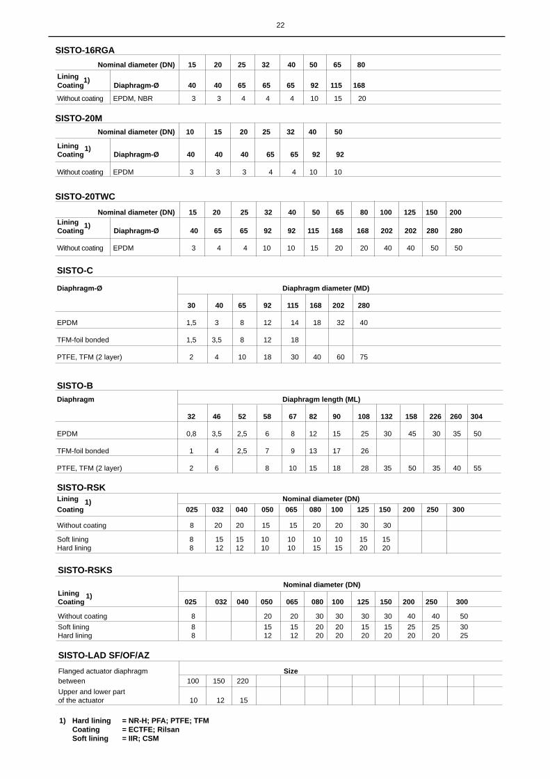
22
SISTO-RSKLining Nominal diameter (DN)Coating 025 032 040 050 065 080 100 125 150 200 250 300 Without coating 8 20 20 15 15 20 20 30 30
Soft lining 8 15 15 10 10 10 10 15 15Hard lining 8 12 12 10 10 15 15 20 20
SISTO-C
Diaphragm-Ø Diaphragm diameter (MD) 30 40 65 92 115 168 202 280 EPDM 1,5 3 8 12 14 18 32 40
TFM-foil bonded 1,5 3,5 8 12 18
PTFE, TFM (2 layer) 2 4 10 18 30 40 60 75
SISTO-BDiaphragm Diaphragm length (ML) 32 46 52 58 67 82 90 108 132 158 226 260 304 EPDM 0,8 3,5 2,5 6 8 12 15 25 30 45 30 35 50
TFM-foil bonded 1 4 2,5 7 9 13 17 26 PTFE, TFM (2 layer) 2 6 8 10 15 18 28 35 50 35 40 55
SISTO-16RGA Nominal diameter (DN) 15 20 25 32 40 50 65 80 Lining Coating Diaphragm-Ø 40 40 65 65 65 92 115 168
Without coating EPDM, NBR 3 3 4 4 4 10 15 20
SISTO-20M Nominal diameter (DN) 10 15 20 25 32 40 50
Lining Coating Diaphragm-Ø 40 40 40 65 65 92 92
Without coating EPDM 3 3 3 4 4 10 10
SISTO-20TWC Nominal diameter (DN) 15 20 25 32 40 50 65 80 100 125 150 200 Lining Coating Diaphragm-Ø 40 65 65 92 92 115 168 168 202 202 280 280
Without coating EPDM 3 4 4 10 10 15 20 20 40 40 50 50
SISTO-LAD SF/OF/AZFlanged actuator diaphragm Sizebetween 100 150 220 Upper and lower partof the actuator 10 12 15
SISTO-RSKS Nominal diameter (DN)Lining Coating 025 032 040 050 065 080 100 125 150 200 250 300
Without coating 8 20 20 30 30 30 30 40 40 50Soft lining 8 15 15 20 20 15 15 25 25 30Hard lining 8 12 12 20 20 20 20 20 20 25
1)
1)
1)
1) Hard lining = NR-H; PFA; PTFE; TFM Coating = ECTFE; Rilsan Soft lining = IIR; CSM
1)
1)

23
11. Addition of the operating instructions, which corresponds to the 94/9/EC Directive (ATEX100)
Security This symbol refers to safety precautions, which must be respected in reference to the use of valves in potentially explosive atmospheres according to the 94/9/EC Directive (ATEX 100a) to avoid personal injuries and damages to property.
♦ You have to mind that inadmissible operating methods are avoided if the valves are used in potentially explosive at-mospheres. In particular, the overstepping of the limitated operating maximum temperature is unacceptable.
♦ The user is bound to only install and use explosion-proof working material in potentially explosive atmospheres.
Installation♦ In principle valves have to be included in the equipotential setting of the system if they are used in potentially explosive
atmospheres.♦ The pneumatic actuators chamber of the type series SISTO-LAP and SISTO-LAD has to be connected to an not explo-
sive air valve or an air tank for ventilating during the use in potentially explosive atmospheres.
Operation ♦ The system and thereby the interior of the valve, which comes into contact with the medium, should always be filled
with conveyed material during the valve‘s use, so that no explosive atmosphere can be created there. The user has to install appropriate monitoring measures if he is not able to guarantee that, see ATEX 100a, appendix II, section 1.5.5 and EN 1127-1.
♦ The surface temperature of the valve‘s body corresponds to the temperature of the transported material. In each case the system‘s user is responsible for the observance of the working temperature. The highest authorized temperature of the material depends on the temperature class in each case.
♦ The heating of the valves components by the environment or by sun radiation shall be avoided.♦ Additional mechanical load on the products (for example external forces and torques) must be avoided.
Maintenance♦ The user is responsible for maintenance works so that no ignition sources appear (for example electrostatic discharge,
mechanically created spark).♦ The user should periodically verify the equipment tightness of the body and the different tightness ranges for example
with the help of a maintenance program. ♦ In principle, dust and dirt should be avoided on all valve surfaces.♦ You have to use a wet cotton cloth to avoid electrostatic discharge while you are cleaning plastic surfaces and plastic-
coated surfaces.♦ The spare parts must be exclusively original SISTO parts.
Declaration♦ Valves are components and they do not have their own potential source of ignition and are thus not covered by the
94/9/EC Directive and must not be indicated by the reference ATEX.
If the instructions laid down for “safety, installation, operation and maintenance/servicing” are not complied with, proper operation of the valve within the meaning of Directive 94/9/EC (ATEX 100a) is not ensured. In this case, the valves must not be used in potentially explosive atmospheres.
The use of faulty valves in potentially explosive atmospheres is not authorized in each case.

SISTO Armaturen S.A.18, rue Martin Maas • 6468 Echternach • (Luxembourg)Tel. (+352) 32 50 85-1• Fax (+352) 32 89 56 • e-mail: [email protected]
0570
.821
-10/
22 -
OR
IGIN
AL
11.0
2.20
16sa
les
docu
men
t, no
tech
nica
l doc
umen
t,al
tera
tions
are
sub
jet t
o te
chni
cal d
evel
opm
ent