manuale operativo eng rev08 2011 parte 2 - …pbpanel.com/en/elfinder/files/m2/operators...
TRANSCRIPT

Operator’s handbook rev08 Operator’s handbook rev08 Operator’s handbook rev08 --- 2011 2011 2011
OPERATOR’S HANDBOOKOPERATOR’S HANDBOOK
Simpo PDF Password Remover Unregistered Version - http://www.simpopdf.com

OPERATOR’S HANDBOOK SUMMARYOPERATOR’S HANDBOOK SUMMARY PART 1 - INSTALLATION HANDBOOK
1.1. Walls built with PSM panel 1.1.1 Foundation anchoring 1.1.2 Storing on the construction site 1.1.3 Identifying the components 1.1.4 Assembling of the panels 1.1.5 Further installation indications 1.1.6 Placement of reinforcement meshes 1.1.7 Electrical and plumbing installation
1.2. Shotcrete application 2.1 Introduction 2.2 Concrete Mix Design 2.3 Application of shotcrete on walls 2.4 Shotcrete curing2.5 Finishes 2.6 Other indications 2.7 Precautions 2.8 Fastenings objects to partitions
1.3 Walls built with PDM double panel 1.3.1 Foundations 1.3.2 Installing double panels 1.3.3 Placing reinforcements on double panels 1.3.4 Completing the panels 1.3.5 Casting operations
1.4 Slabs with PSS1 panel 1.4.1 Installation of single panel slab 1.4.2 Completing single panel slab
1.5 Joist slabs with PSSG slab panel 1.5.1 Slabs with PSSG slab panel1.5.2 Installing PSSG slab panel 1.5.3 Completing the PSSG slab panels 1.5.4 Calculations and verifications of PSSG slab panel
1.6 Staircases, landings and balconies 1.6.1 Use of staircase and landing panels 1.6.2 Balcony construction 1.7 Cladding and partition walls 1.7.1 Panel installation 1.7.2 Completing on site 1.8 Insulating cover with EMMEDUE panels 1.8.1 Installation of the Emmedue insulating cover panel
PART 2. RICAPITULATION OF OPERATING STEPS 2.1 Walls built with PSM panel 2.2 Shotcrete application 2.3 Walls built with PDM double panel 2.4 Slabs built with PSS1 panel 2.5 Slabs built with PSSG slab panel 2.6 Staircases, landings and balconies 2.7 Cladding and partition walls 2.8 Insulating covers with PST-C panel
PART 3. CONSTRUCTION DETAILS
Simpo PDF Password Remover Unregistered Version - http://www.simpopdf.com

PART 1:PART 1:
INSTALLATION MANUAL INSTALLATION MANUAL
Operator’s handbook rev08 Operator’s handbook rev08 Operator’s handbook rev08 --- 2011 2011 2011
Simpo PDF Password Remover Unregistered Version - http://www.simpopdf.com

Pag. 4 Cap.1.1 - Walls built with PSM panel
Operator’s h
andbook r
ev08 - 2
011
CHAPTER 1.1CHAPTER 1.1
WALLS BUILT WITH PSM PANELWALLS BUILT WITH PSM PANEL
1.1.1 FOUNDATION ANCHORING1.1.1 FOUNDATION ANCHORINGThe anchoring of the panels on the foundations should take place by forese-eing the placement of rebars of number, length and diameter according to the calculated stress at the base of the panel.(Indicative rebars may be a 6-8mm (0.24-0.32 in) diameter for intervals of 30-40 cm(12-16 in) and for an exterior length of 40 cm(16 in).
Simpo PDF Password Remover Unregistered Version - http://www.simpopdf.com

Pag. 5
Operator’s h
andbook r
ev08 - 2
011
Cap.1.1 - Walls built with PSM panel
1.1.2 STORING 1.1.2 STORING ONON THETHE CONSTRUCTIONCONSTRUCTION SITESITEAn area inside the site, preferably covered, shall be designated for depositing panels from the manufacturer. The panels must be layed down carefully on a flat surface, which is not pliable, so they can be vertically stacked. We recom-mend not to lay the elements directly on the ground to prevent them from get-ting dirty, which could lead to problems of plaster adhesion. It is also advisable to protect them from the rain for the same reasons. The panels must not be ex-
posed to sunlight for long periods of time in order to prevent chang-ing the polystyrene appearance. Moreover, the panels should be bound carefully to make sure they are not accidentally moved by the wind.
1.1.3 IDENTIFYING 1.1.3 IDENTIFYING THETHE COMPONENTSCOMPONENTSThe panels are delivered to the site with an identification issued by the manu-facturer that reports the element height. The panel layout comes with the pan-els and provides instruc-tions for laying the com-ponents correctly. The panel layout, for each elevation, reports the design for the various alignments of the struc-ture, as well as the layout in the floor panel plans. Instructions on cutting to obtain dimensions that are not standard are also provided. (Fig.1)
Fig. 1 –Panel layout
Simpo PDF Password Remover Unregistered Version - http://www.simpopdf.com

Pag. 6 Cap.1.1 - Walls built with PSM panel
Operator’s h
andbook r
ev08 - 2
011
1.1.4 ASSEMBLING 1.1.4 ASSEMBLING OFOF THETHE PANELSPANELSEmmedue panels are an-chored to the foundation bars by pliers and steel wires. In order to ensure the continuity among the components, pan-els are equipped, on both sides, with an overlapping mesh wing that enables the operator to join adjacent pan-els.At this stage, to achieve proper heat insulation, no empty spaces should be left
between the joints of polystyrene cores.During assembling the main open-ings for doors and balconies have to be taken under consideration in advance.Minor openings can be addressed after assembling panels by using cutting instruments, such as circular saws, shears and even knives and pliers.
Simpo PDF Password Remover Unregistered Version - http://www.simpopdf.com

Pag. 7
Operator’s h
andbook r
ev08 - 2
011
Cap.1.1 - Walls built with PSM panel
1.1.51.1.5 FURTHERFURTHER INSTALLATIONINSTALLATION INDICATIONSINDICATIONSWe recommend to begin the layout from a building corner and proceed by completing each single room that makes up the project. Proper assembly re-quires scrupulously checking wall flatness and corner verticality using a simple plumb line.To ensure flatness, we recommend the use of aluminium box profiles of 4 me-ters (13 ft.) of length and adjustable diagonal pillars to anchor firmly into the ground. In particular, for normal landings, one box is enough to place near the panel top plates and inclined pillars at an interval of about one every 3 m.(10 ft). We recommend placing the diagonal pillars on one side to completely free the other and be able to proceed faster during the rendering process.
Only after applying the first layer of structural plaster on the accessible part of the panel’s surface, proceed by removing the pillars and applying the structural plaster on the surface formerly covered by the pillars.The indications mentioned above help avoid dangerous eccentricities at the end of the work.Moreover, in order to correct the finished wall’s verticality, one would use an excessive quantity of finishing, resulting in wasting of time and materials.
Simpo PDF Password Remover Unregistered Version - http://www.simpopdf.com

Pag. 8 Cap.1.1 - Walls built with PSM panel
Operator’s h
andbook r
ev08 - 2
011
1.1.61.1.6 PLACEMENTPLACEMENT OFOF REINFORCEMENTREINFORCEMENT MESHESMESHESAngular meshes (RG1)All the building internal and external corners, either vertical or horizontal, are reinforced with angular meshes (RG1), which are attached to the structural mesh of the panels.
Flat Meshes (RG2)The openings are all braced, on both sides, by positioning a flat meshwork (RG2) at 45° on each corner.The window and door lintels, according to their length and the window sills, whose span is longer than 1,2 m. (4 ft). shall be additionally reinforced from both sides.
Simpo PDF Password Remover Unregistered Version - http://www.simpopdf.com

Pag. 9
Operator’s h
andbook r
ev08 - 2
011
Cap.1.1 - Walls built with PSM panel
U Meshes (RU)
Along the perimeter of the door and window openings, reinforcement U mesh or, as an alternative, double angular mesh (RG1) shall be placed with sealing panel.
The assembling of the frames requires the polystyrene to be cut out in the ar-eas of the frame fastening points, to enable the correct insertion of metallic clamps inside the panel’s mesh.
Building with PDM walls Building with PSM walls
For specific types of frames ,special requirements, or to ensure the absence of thermal bridges along the opening’s perimeter, no reinforcement meshes may be applied. (see details).
Simpo PDF Password Remover Unregistered Version - http://www.simpopdf.com

Pag. 10 Cap.1.1 - Walls built with PSM panel
Operator’s h
andbook r
ev08 - 2
011
1.1.71.1.7 ELECTRICALELECTRICAL ANDAND PLUMBINGPLUMBING INSTALLATIONINSTALLATION
The steps to install the flexible electrical piping as well as the rigid plumbing piping, are done after completing the assembling of the panels and before the application of structural plaster .The traces shall be directly obtained in the polystyrene core, preferably using a jet of hot air instead of an open flame, in order to avoid reducing excessively the thickness of the polystyrene and ensuring so, the presence of wall insula-tion for at least 4 cm.(1.6 in).If under extraordinary circumstances, it is not possible to insert the units into
the walls, casings shall be created. Any cuts on the mesh correspond-ing to electric boxes or other acces-sories with dimensions greater than standard, shall be restored with flat reinforcement mesh RG2 before the application of the structural plaster.
Simpo PDF Password Remover Unregistered Version - http://www.simpopdf.com

Pag. 11
Operator’s h
andbook r
ev08 - 2
011
Cap.1.1 - Walls built with PSM panel
Flexible pipes are easily placed under the meshwork, whereas rigid ones are placed after cutting the mesh. Consequently, the meshwork area needs to be restored by placing an additional reinforcement mesh (RG2) connected to the panel meshwork.
Note: Copper pipes should be isolated from the steel mesh using felt,PVC or similar
Simpo PDF Password Remover Unregistered Version - http://www.simpopdf.com

Pag. 12 Cap.1.2 - Shotcrete application
Operator’s h
andbook r
ev08 - 2
011
CHAPTERCHAPTER 1.2 1.2
SHOTCRETE SHOTCRETE APPLICATIONAPPLICATION 1.2.1 INTRODUCTION 1.2.1 INTRODUCTIONEmmedue’s single panel used as a supporting element is completed by apply-ing cement-sand structural plaster on both sides for an average thickness of 3.5 cm (1.38 in). The panel forms a reinforced concrete wall with an expanded polystyrene core.
1.2.2 CONCRETE MIX 1.2.2 CONCRETE MIX DESIGNDESIGNThe cement-sand plaster used is dosed with a volumetric ratio of 1:4. Starting from the resistance curves obtained in relation to both the amounts of cement and plaster settling, it may be derived that the concrete may be mixed with approx. 267 kg (589 lbs.) of cement for each cubic yard of mixture.For each cubic yard, the specified weight for each of the materials in the mix-ture is as follows:
The quantity of water should vary according to the humidity of the aggregates. In any case the workability, measured by the Abram’s cone, should be S2 (slump 5 cm.(2 in.)).
1.2.3 APPLICATION 1.2.3 APPLICATION OFOF SHOTCRETESHOTCRETE ONON WALLSWALLSPlaster will be applied by means of special plaster spraying equipment.It is essential that plaster is malleable and applied vigorously so as to remove the air between the underlying materials - polystyrene and plaster - and com-pact with a uniform surface.The maximum thickness of the first layer should be approx.2.5 cm. (1 in.) while the layer of smooth plaster with fine sand, if required, should not exceed 0.6 cm-1.2 cm(0.25-0.5 in).Plastering excessively large areas is a practice to be avoided.
Cemento : 350 Kg (772 lbs) Sabbia : 1600 Kg (3527 lbs) Acqua : 160 litri
Simpo PDF Password Remover Unregistered Version - http://www.simpopdf.com

Pag. 13
Operator’s h
andbook r
ev08 - 2
011
Cap.1.2 - Shotcrete application
Following the panels’ assembling, a required bracing meshwork will be in-stalled and the cut meshwork will be restored. This will provide a continuous structure, where specified additional reinforcements will be placed. At this stage, structural plastering operations may commence.
On both sides of vertical panels a layer of structural plaster (Rck = 25 Mpa (3556 PSI)) should be sprayed for an average thickness of approx. 2.5cm ( 1 in.) The second layer should be applied only after the first one is sufficiently har-dened. At the end of the curing process the resulting structural plaster should
have a resistance of 25 MPa.
Simpo PDF Password Remover Unregistered Version - http://www.simpopdf.com

Pag. 14 Cap.1.2 - Shotcrete application
Operator’s h
andbook r
ev08 - 2
011
In case of rain, it is recommended to interrupt the work and cover what has already been done in or-der to prevent the fresh structural plaster from washing away. The shotcrete should not be ap-plied when the outside tempera-ture is less than 4ºC, when tem-peratures are high (>30ºC) and when there is ventilation. The layer of structural plaster should be kept damp or protected with anti-evaporating materials for at least 3 days.In order to ensure that the layer of concrete is perfectly flat, guides of plaster shall be preliminarily formed on site, at intervals of about 1.5 m.(5 ft.) or, alternatively, metallic profiles will be used at that end. Those are to be removed from the fresh concrete to avoid the subsequent formation of cracks due to the material’s interruption.Soon after the shotcrete application is finished, one may remove the guides. The day after, the pillars u-sed for the alignment and plumbing of the panels, may be removed. Those that are used on structurally weak points, (in between two openings for example) are to be left in place until the curing process achieves a higher degree of completion.
Simpo PDF Password Remover Unregistered Version - http://www.simpopdf.com

Pag. 15
Operator’s h
andbook r
ev08 - 2
011
Cap.1.2 - Shotcrete application
1.2.4 SHOTCRETE 1.2.4 SHOTCRETE CURINGCURINGA regular plaster curing process is crucial to obtain the necessary struc-tural quality of the elements. In order to avoid an excessive evaporation from the plaster surfaces, after the surface is completed, keep con-stantly wet the walls and the ceilings for at least 2 days from the moment of the application of the plaster layer. This procedure will favour the natural hydration process of the cement, and will reduce hair cracking due to hy-draulic shrinkage. Whenever anti-evaporating films are used, it is important to preventively check for any adhesion problems for the subsequent finish application. .1.2.51.2.5 FINISHESFINISHESIn order to avoid or if needed correct the appearance of hair cracks, one should apply the finishing layer only after the curing process has been completed.1.2.61.2.6 OTHEROTHER INDICATIONSINDICATIONSThe use of a plaster sprayer for the applica-tion of the structural plaster increases the compactness and homogeneity, reducing the level of shrinkage and improves the struc-ture’s water resistance and durability. Polystyrene does not constitute special waste and can be disposed of in bins for RSU plastics. The steel can be recovered and taken to au-thorized collection centres..
Simpo PDF Password Remover Unregistered Version - http://www.simpopdf.com

Pag. 16 Cap.1.2 - Shotcrete application
Operator’s h
andbook r
ev08 - 2
011
1.2.71.2.7 PRECAUTIONSPRECAUTIONS::
�Do not overload partition walls on one side only. Instead, apply plaster on both sides alternatively.
�Whenever a panel may lack an overlapping mesh because of eventual nec-essary cuts, it is necessary to restore the continuity of adjacent panels by the use of a flat mesh (min. width 23 cm (9 in.));
�Additional plasticizers will generally reduce the risk of cracks; �Highly-flexible coverings or paints may prevent the creation of cracks on the
plaster;1.2.81.2.8 FASTENINGFASTENING OBJECTSOBJECTS TOTO PARTITIONSPARTITIONSA.Light objects:
2.5 cm (1 in.) long screws, pins or similar devices may be used. (Fig. 1).
B. Heavy objects:
(Shelves, water-tanks, toilets, etc.). We recommend the use of plastic anchors with 2-2.5cm (1-3/4 in.) long screws or similar devices (Fig.1)
C. Very heavy objects:
During construction, metal pins may be inserted in plaster an-chors. Also threaded pins may be fastened with epoxy resin (Fig.3).
Simpo PDF Password Remover Unregistered Version - http://www.simpopdf.com
Pag. 17
Operator’s h
andbook r
ev08 - 2
011
Cap.1.3 - Walls built with PDM panel
CHAPTER 1.3CHAPTER 1.3
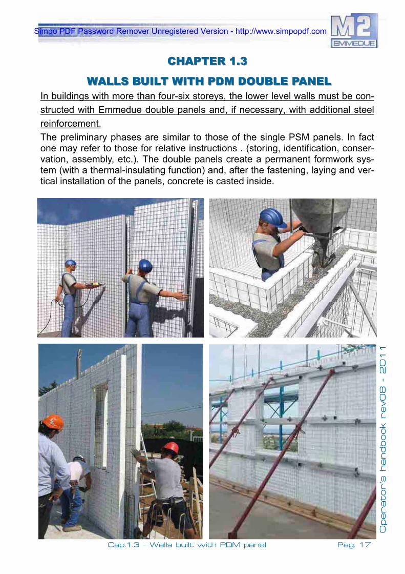
WALLSWALLS BUILTBUILT WITHWITH PDMPDM DOUBLEDOUBLE PANELPANELIn buildings with more than four-six storeys, the lower level walls must be con-structed with Emmedue double panels and, if necessary, with additional steel reinforcement.The preliminary phases are similar to those of the single PSM panels. In fact one may refer to those for relative instructions . (storing, identification, conser-vation, assembly, etc.). The double panels create a permanent formwork sys-tem (with a thermal-insulating function) and, after the fastening, laying and ver-tical installation of the panels, concrete is casted inside.
Simpo PDF Password Remover Unregistered Version - http://www.simpopdf.com

Pag. 18 Cap.1.3 - Walls built with PDM panel
Operator’s h
andbook r
ev08 - 2
011
1.31.3.1.1 FOUNDATIONSFOUNDATIONSThe reinforcements shall be placed tak-ing special care when aligning, due to the moderate thickness of the inter-spaces (from 10-30 cm.(3.9 to 11.8 in.)) of the double panels that are normally used.The number, diameter and length of the reinforcement bars depend on the stress on the base of the panels (as de-duced by relative calculations). The ex-ternal distance of the rebars should be meticulously maintained, in order to avoid problems during the panel inser-tion in place. It is best to use closed re-inforcements at the head in order to fa-cilitate the insertion from above, of the panels.
The rebars, if properly placed, help to keep the panels properly aligned and upright. If the panels are against the earth or otherwise stressed on the vertical plane, the rebars design should take that stress under consideration always in accordance with the structural analy-sis.At the panel base, regulator boards must be placed firmly into the ground to ensure alignment and help with the positioning of the reinforcement elements
Simpo PDF Password Remover Unregistered Version - http://www.simpopdf.com

Pag. 19
Operator’s h
andbook r
ev08 - 2
011
Cap.1.3 - Walls built with PDM panel
1.31.3.2.2 INSTALLINGINSTALLING DOUBLEDOUBLE PANELSPANELSPanel assembly should take place only after having verified the conformity to the project instructions and to the assembly abacus of the elements supplied . It should be verified that after moving and storage procedures, the panels and internal mesh are still intact and that they are properly positioned (distance of the slabs). The panels are equipped on production with appropriate steel rein-forcement; if additional reinforcement is required, in accordance with the struc-tural designs, we recommend placing it on site and fixing it at the base and at the head of the panel. The additional bars should be placed inside the mesh in order to ensure adequate cover. All procedures should follow the indications of the structural designs and take place under the supervision of the project supervisor. The panels should be placed on site from above, one after the other, avoiding any horizontal movement that could be hindered or made difficult by the rein-forcement bars.Panels’ placement should be accompanied by the insertion of connection brackets, laid according to the project design, that will serve to make the sub-sequent concrete filling continuous. For that purpose, Emmedue produces ap-propriate SPD. At this point extra care should be taken to ensure the alignment and verticality of the panels. Also the perfect fit of consecutive panels should be ensured. Cases of out of plumb panels will create weak structural points and empty spaces between consecutive panels may create thermal bridges. To guarantee the continuity of the components, Emmedue panels are equipped on both sides with an overlapping mesh enabling so the joining of adjacent panels.
Simpo PDF Password Remover Unregistered Version - http://www.simpopdf.com

Pag. 20 Cap.1.3 - Walls built with PDM panel
Operator’s h
andbook r
ev08 - 2
011
Sealing between one panel and the next can be carried out using pneumatic machines produced by Emmedue, or by manually binding them. The bonds are carried out along the overlapped wires at the rate of about one every 25 cm.(10 in.) (one link every four).The indications mentioned above help avoid dangerous eccentricities at the completion of the structure. Such circumstances, if not kept under control, could have unfavourable repercussions for the out of plumb effect that induces bending action (the P-Delta effect). Moreover, to bring the finished wall back to vertical position you would use excessive finishing material resulting in burden-some waste of time and product. During assembly procedures, it is important to keep in mind the project open-ings according to the indications of the assembly abacus. Be warned that any modification of the openings or the creation of new ones, constitutes a struc-tural modification and is a procedure with serious implications. In order to insert additional reinforcements at the head of doors and windows one may exploit the support of the transversal connectors.
Simpo PDF Password Remover Unregistered Version - http://www.simpopdf.com

Pag. 21
Operator’s h
andbook r
ev08 - 2
011
Cap.1.3 - Walls built with PDM panel
1.31.3..33 PLACINGPLACING REINFORCEMENTSREINFORCEMENTS ONON DOUBLEDOUBLE PANELSPANELSIn correspondence to all the junctions as well as next to the opening and end portions of the walls, adequate reinforcements shall be placed using vertical reinforcement bars. The reinforcements may be clamped (and entirely inserted into the panel) or confined with U rods and inserted externally. In any case, wall continuity must be ensured, even on joints, in order to resist to the shear forces estimated by the structural analysis. Besides horizontal and vertical reinforcements to place in the wall panels and/or cross panels, normal reinforcements used for the PSM constructions shall be placed. (flat and angular meshes.)
Pic.1-2Details of reinforcements insertion at the points of wall intersections and wall corners.
stirrup ø5/25
var.
RG1
2ø16
stirr
up ø
5/25
var.
RG1
RG1RG1
stirr
up ø
5/25
2ø16
var.
Simpo PDF Password Remover Unregistered Version - http://www.simpopdf.com

Pag. 22 Cap.1.3 - Walls built with PDM panel
Operator’s h
andbook r
ev08 - 2
011
1.31.3.4.4 COMPLETINGCOMPLETING THETHE PANELSPANELSBefore casting procedures, make sure that the walls are positioned correctly, perfectly aligned, plumbed and blocked sufficiently to cope with the dynamic ac-tions of concrete casting. To that effect, be advised that thanks to the 30 kg/mc density of the PDM’s polystyrene the panel is capable of withstanding most of the thrust caused by the concrete casting procedure. Further reinforcement may be obtained with metallic trusses embracing the panel from both sides. It is therefore necessary the placement of props on both sides that, besides vertical-ity, ensure stability during the casting procedure. The centre distance of such components may be about 10 ft. The function of trusses may very well be per-formed by an aluminium box profile, wood walls, boards connected with metal ties, iron wires or round bars with clamps. If slabs or bars passing through the panels are used, it is best to cover them with plastic sheaths to reduce expo-sure to the casting and be able to simply unthread once the procedure is fin-ished and avoid cutting.It is important that the first row of reinforcement is placed at the panel base
where there is greater thrust. For a typical wall height 2.7m.(8.9 ft.), 4 horizontal rows of reinforcement may be placed starting from the base and proceeding in subsequent in-tervals of 0.4,0.7,1 m.(1.3, 2.3, 3.3 ft.) Usually, the level of the casting does not reach the panel top but stops at about 30cm.(1.1 ft.) lower in order to place the reinforcement rebars from the panel to the next level. The filling will be com-
pleted at the same time as the floor casting. The stiffeners shall be connected to each other at an average interval of 50 cm.(1.6 ft.) . If a casting-block is present, the emerging part of the panel must be secured, at a centre distance of about 1.6 ft., to the mesh and/or upper rods of the floor to avoid damages that can be caused by the concrete thrust.
Simpo PDF Password Remover Unregistered Version - http://www.simpopdf.com

Pag. 23
Operator’s h
andbook r
ev08 - 2
011
Cap.1.3 - Walls built with PDM panel
In correspondence to the panel edges, covers with boards and inclined pillars fixed firmly on the ground must be carried out.Do the same in correspondence to the openings (doors and windows), where a crowning contrasted by pillars (horizontal and vertical) must be placed at about every 1m (3.3 ft.) 1.31.3..55 CASTINGCASTING OPERATIONSOPERATIONSThe indications, known to the technicians, about the correct procedures to fol-low when casting and all inspections to carry out before, during and after the procedures will be omitted. Other aspects are reported though that should be kept in mind, when using Emmedue panels.First of all, the mix design should contain aggregates of a maximum diameter of 1.2 cm (0.47 in.), a high workability (slump S5) and mechanical resistance usually greater than 25 Mpa (3556 PSI) and in any case corresponding to that of the project designs.The casting procedures can be carried out with buckets or with the use of an auto-pump; for the latter, an appropriate casting tube of rectangular section may be fabricated, in order to better convey the concrete in between the walls without waste of material. The casting procedures must proceed gradually, fill-ing the panels with concrete layers of a maximum thickness of 80 cm (2.6 ft.) for each pass and letting it set for a few minutes. The velocity of casting along the walls should not be superior to 3 m of height/hour (9 ft of height/hour).
Simpo PDF Password Remover Unregistered Version - http://www.simpopdf.com

Pag. 24 Cap.1.4 - Slabs built with PSS! panel
Operator’s h
andbook r
ev08 - 2
011
1.41.4..1 INSTALLATION OF SINGLE PANEL SLABS1 INSTALLATION OF SINGLE PANEL SLABSBasicaly the same instructions relative to the vertical single panels are ap-plied , meaning that it is necessary to proceed first with the correct placement of the components and afterwards with their joi-ning (along the overlap-ping meshes).
At the end one should p r o c e e d w i t h t h e connection of walls by the means of steel bars and/or reinforcement meshes RG1. The panels that fun-ction as slabs, are placed with the wave paralel to the minimum span of the covering area. Panels are supported by bridges made of boards and props , placed at intervals of aproximately 60 cm (23.62 in.). A camber of 0,25 cm (0.1 in) should be formed for every meter of slab length.
CHAPTER 1.4CHAPTER 1.4
SLABS WITH PSS1 PANELSLABS WITH PSS1 PANEL
Simpo PDF Password Remover Unregistered Version - http://www.simpopdf.com

Pag. 25
Operator’s h
andbook r
ev08 - 2
011
Cap.1.4 - Slabs built with PSS! panel
1.4.21.4.2 COMPLETINOCOMPLETINO SINGLESINGLE PANELPANEL SLABSSLABSOnce the assembly of the slab props is finished and after the application of shotcrete on the walls, it is time to apply the first layer of structural plaster on the ceiling. After at least 24 hours have passed from the moment the
shotcrete is applied, the casting of concrete on the slab floor may take place. During the casting procedure, the opera-tors should keep in mind to walk only on the board bridges supported by the props that are found underneath.The designer should verify in advance the slab reinforcements, that if nee-ded may be completed with
additional steel bars in accordance with the structural analysis . The concrete to be used should be of a resistance of Rck � 25 MPa with a maximum aggre-gate diameter of 12mm (0.5 in) and a grade of workability S4. The concrete slab thickness will vary between 4 and 6 cm (1.6 and 2.4 in). Once the concre-te slab’s curing has taken place, the props are gradually removed, starting from the center and proceeding towards the extremes, gradually loading so, the slab.
After that, the shotcrete application may be completed on the ceiling and where the prop boards where placed.The second layer of plaster on the ceiling is ap-plied the same way it was applied to the walls.
Simpo PDF Password Remover Unregistered Version - http://www.simpopdf.com

Pag. 26 Cap.1.5 - Slabs built with PSSG panel
Operator’s h
andbook r
ev08 - 2
011
1.5.11.5.1 JOISTJOIST SLABSSLABS WITHWITH PSSGPSSG SLABSLAB PANELPANELThis type of panel completes the field of ap-plication of the single wavy PSS1 panel, sin-ce it allows for greater span constructions up to 8-9 m (26-30 ft). The panels function as lightweight formwork and create resistant components of unidirectional behaviour that are finished on site. The concrete fills in the joists and forms an upper slab of variable thickness of 4 to 6 cm.(1.6 to 2.4 in.) depen-ding on the specific conditions.(loads,spans ecc.). Concrete with a resistance of 25 Mpa is to be used, always in accordan-ce with the structural design and with aggregates of maximum diameter of 12 mm (0.47 in).
1.5.2 INSTALLING PSSG 1.5.2 INSTALLING PSSG SLABSLAB PANELSPANELSThe reinforcements that are present in the panel, allow for prop placement at intervals of 1,20-1,30 meters (3.9-4.1 ft.). The height of the props at the center of the slab is increased in order to form a camber of aproximately 0,25 cm (0.1 in.) for every meter (3.3 ft) of span.The steel bars to be placed internaly in the joists, are put in place when the slab panel lies on the ground.The bars may reach the site already bent and of the right length in order to be anchored to the walls.
CHAPTER 1.5CHAPTER 1.5
SLABS WITH PSSG PANELSSLABS WITH PSSG PANELS
Simpo PDF Password Remover Unregistered Version - http://www.simpopdf.com

Pag. 27
Operator’s h
andbook r
ev08 - 2
011
Cap.1.5 - Slabs built with PSSG panel
See the indications given for the single slab panel, meaning that it is neces-sary to proceed first by joining the single components and afterwards by joining them with the walls using steel bars and/or reinforcement meshes. Joist rein-forcements, to be placed before casting the concrete, are to be verified for the specific conditions of loads or structural formations such as cantilevers and/or slabs. Apart from those reinforcements, at the points of the wall supports rein-forcement meshes are to be placed, before the rendering.. Once the casting is done and the props are gradually removed, (Time of removal according to indi-cations by the project supervisor) the application of plaster on the ceiling is in order.
1.5.31.5.3 COMPLETINGCOMPLETING THETHE PSSGPSSG SLABSLAB PANELSPANELS..
Simpo PDF Password Remover Unregistered Version - http://www.simpopdf.com

Pag. 28 Cap.1.5 - Slabs built with PSSG panel
Operator’s h
andbook r
ev08 - 2
011
1.5.4 CALCULATIONS 1.5.4 CALCULATIONS ANDAND VERIFICATIONSVERIFICATIONS OFOF THETHE PSSGPSSG SLABSLABPANELPANEL..Follows a series of diagrams and tables that may be used for the designing of the
slabs. The limit state theory has been used in order to perform the calculations and
verifications.
Be advised that for the designing of slabs and according to Italian regulations, the mi-
nimum thickness ought to be greater than 1/25 of the calculation span and a function
of the loads so as to obtain deflections compatible with the end use of the slab.
Moments and Shear force of a PSSG LIMIT STATE VERIFICATION
Joist interaxis i = cm 56 Joist width l = cm 10 Assumed reinforcement as an example 2+2 Ø12/ joist Cls Rck 30 Mpa
SLAB HEIGHT Self weight
(without plaster)
Limit Moment Limit Shear
SLAB Single joist Single joist
TYPE joist slabKg/mq
MRd+ MRd- VRd1 VRd2
h (cm) s (cm) (kNm) (kNm) (kN) (kN)
PSSG 12+4 12 4 160 11,2 -10,4 10,8 56,4
PSSG 14+4 14 4 170 12,9 -12 11,6 64,5
PSSG 16+4 16 4 180 14,5 -13,7 12,4 72,5
PSSG 18+4 18 4 190 16,2 -15,4 13,2 80,6
PSSG 20+4 20 4 200 17,8 -17,1 13,9 88,7
PSSG 22+4 22 4 210 19,5 -18,8 14,7 96,7
PSSG 24+4 24 4 220 21,1 -20,4 15,4 104,5
PSSG 26+4 26 4 230 22,8 -22,1 16 112,8
Simpo PDF Password Remover Unregistered Version - http://www.simpopdf.com

Pag. 29
Operator’s h
andbook r
ev08 - 2
011
Cap.1.5 - Slabs built with PSSG panel
q
L
PSSG slab panel preliminary design The following diagram may be used for an instant rough designing of the EMME-DUE slab. The designing of the slab is a function of the calculation span and of the loads. The different curves represent different sections of the PSSG panel where the first number identifies the height of the joist slab in EPS and the second number stands for the concrete slab, assuming additional reinforcement of 2+2 Ø 12/ joist.
Simpo PDF Password Remover Unregistered Version - http://www.simpopdf.com

Pag. 30 Cap.1.6 - Staircases, Landings and Balconies
Operator’s h
andbook r
ev08 - 2
011
CHAPTER 1.1.6CHAPTER 1.1.6
STAIRCASES, LANDINGS AND BALCONIESSTAIRCASES, LANDINGS AND BALCONIES
1.6.1 USE OF STAIRCASE AND LANDING PANEL1.6.1 USE OF STAIRCASE AND LANDING PANELThe staircase panel is used to build staircase slabs for up to 6 meter (19.7 ft) spans (live load of 400kg/m2)(81 lbs/ft²). First the staircase panel is placed, the reinforcement bars are positioned in it’s cavities and the panel is bound to the extremes of the upper mesh. Afterwards, the cavities are filled with concrete containing aggregates of a maximum diameter of 12 mm(0.47 in) and a resi-stance of Rck �25 MPa ( 3556 PSI) or in any case what the designer has deter-mined.The casting of the concrete in the joists may take place only after the appro-priate props are placed beneath the stair slab. The supports are formed by bo-ards or wooden beams at intervals of 80-100 cm (2.7-3.3 in). Next, one may proceed by applying the plaster on the lower surface of the stair slab and afterwards by casting the mortar on the upper surface with a medium thickness of 2,5 cm (1 in.), creating so, the base for the coating . (marble, tiles, ecc.)For spans that exceed the length of 4 meters(13.12 ft), it is advisable to create points of continuity between the beam and the mortar that lies above, by cutting out portions of polystyrene at the meeting point of tread and riser,in a
in order to form the tread . The staircase panel, allows the building of staircases of conventional di-mensions and it e-xcells for it’s extraordi-nary ease of installa-tion and structural light weight.
Simpo PDF Password Remover Unregistered Version - http://www.simpopdf.com

Pag. 31
Operator’s h
andbook r
ev08 - 2
011
Cap.1.6 - Staircases, Landings and Balconies
1.6.21.6.2 BALCONY CONSTRUCTIONBALCONY CONSTRUCTION
Balconies may be built by using slab paneIs that are completed if needed with additional reinforcement bars, anchored on the slab panel itself. The number and diameter of such reinforcements and the thicknes of the concrete slab, de-pend on the length of the cantilever and the quantity of dead and live load that are considered in the calculation assumptions. Only after the curing is comple-ted, one may advance with the removal of the props and the application of the plaster on the ceiling.
Simpo PDF Password Remover Unregistered Version - http://www.simpopdf.com

Pag. 32 Cap.1.7 - Cladding and Partition walls
Operator’s h
andbook r
ev08 - 2
011
CHAPTERCHAPTER 1.7 1.7
CLADDINGCLADDING ANDAND PARTITIONPARTITION WALLSWALLS
1.7.1 PANEL 1.7.1 PANEL INSTALLATIONINSTALLATIONA preliminary marking of partition tracks is in order along all the wall sides. Special attention is needed for the plumbing and alignment .The fixing of the panels may take place by using c shaped steel sections, of width equal to the thicknes of the panel, that are fixed on the supporting structure with pressure nails or rebars. In case of rebars, they would first have to be fixed on the sup-porting structure at an adequate depth and sealed with epoxy resine at inter-vals of aproximately 40 cm (1.3 ft). The rebars are then bound to both sides of the panel perimeter.The rebars may be of a diameter of aproximately 6 mm (1/4 in) and a length of aproximately 50 cm (19.7 in).
The anchorage length, the diame-ter and intervals of the rebars, ha-ve to be verified according to the effective static scheme and the for-ces in action. Present indications have to be ve-rified for specific types of partition walls or loads that are out of the ordinary standards.
Simpo PDF Password Remover Unregistered Version - http://www.simpopdf.com

Pag. 33
Operator’s h
andbook r
ev08 - 2
011
Cap.1.7 - Cladding and Partition walls
Should it be necessary to create joints, an elastic membrane or a stripe of pol-ystyrene should be placed, before installing the panels. The width of such com-ponents should be greater than that of the rendered panel thickness making it so that the plaster of the panel hasn’t got any point of contact with the panel from which it should be separate. In that case, the rebars would have to be a-ble to move freely in their cavities. The panels should be installed, preferably before casting the screed. Also, when rebars are used, those are placed first on one side of the future position of the panel, then the holes are drilled for the rebars on the other side and at last , the panel is placed. After fixing the panels on the rebars from one side, proceed with anchoring the rebars on the other side and fixing them to the panels. As for the positioning of the reinforcement meshes and the installation of piping, make reference to pre-vious paragraphs. Extra attention should be paid to the plumbing and alignment of the panels be-fore the impending rendering. In order to guarantee the necessary durability, it is adviseable for exterior walls to use zinc coated steel.1.7.2 COMPLETING 1.7.2 COMPLETING ONON SITESITEIn order to render the walls, any type of cement based plaster, even premixed, may be used, for a thickness of 2-2,5 cm (0.8-1 in). Standard procedures and manufacturer’s indications are to be applied.To avoid the appearence of cracks it is adviseable to apply the plaster in two consecutive layers.The first layer should slightly cover the mesh and the second layer should be applied only af-ter the first layer has gained some resistance. An eventual final layer of rende-ring should be applied only after the curing of the plaster has been completed.
Simpo PDF Password Remover Unregistered Version - http://www.simpopdf.com

Pag. 34 Cap.1.8 - Insulating covers with PST-C panel
Operator’s h
andbook r
ev08 - 2
011
CHAPTERCHAPTER 1.8 1.8
INSULATING INSULATING COVERCOVER WITHWITH EMMEDUEEMMEDUE PANELSPANELS
1.8.1 INSTALLATION 1.8.1 INSTALLATION OFOF THETHE EMMEDUEEMMEDUE INSULATINGINSULATING COVERCOVERPANELPANELThe fixing of the panels is achieved through the use of cement based a-dhesive mortar. The adhesive is ap-plied in stripes and points. Follows the mechanical fixing by me-ans of tailspin anchoring with steel nails and plastic heads appropriate for the supporting structure where they will be used. The length of the nail should be enough to penetrate the supporting layer for at least 70 mm (2.75 in). The anchorings should always be used following the manu-facturer’s indications.
Simpo PDF Password Remover Unregistered Version - http://www.simpopdf.com

Pag. 35
Operator’s h
andbook r
ev08 - 2
011
Cap.1.8 - Insulating covers with PST-C panel
Flat meshes should be placed at each corner at an angle of 45° degrees. Whe-rever there are mesh interruptions it is necessary to restore continuity by atta-ching stripes of flat meshes on the specific area. The same procedure is to be followed where panels have no overlapping meshes. In order to follow a correct procedure of rendering, it is advisable to avoid working under temperatures that are lower than +5°C or higher than +30°C. Al-ways keep clean supporting surfaces from dirt, dust, incoherent parts, ecc. and always verify in advance it’s correct alignment. Once the plaster’s curing period has passed, proceed by applying the final smoothing layer where a thin mesh of glass fiber or plastic material may be u-sed.
Simpo PDF Password Remover Unregistered Version - http://www.simpopdf.com

Simpo PDF Password Remover Unregistered Version - http://www.simpopdf.com

PART 2:PART 2:
OPERATING OPERATING STEPS SUMMARY STEPS SUMMARY
Operator’s handbook rev08 Operator’s handbook rev08 Operator’s handbook rev08 --- 2011 2011 2011
Simpo PDF Password Remover Unregistered Version - http://www.simpopdf.com

Pag. 38 Chap. 2.1 - Walls built with PSM panels
Operator’s h
andbook r
ev08 - 2
011
CHAPTER 3.1CHAPTER 3.1 WALLS BUILT WITH PSM PANELS WALLS BUILT WITH PSM PANELS
3.1.13.1.1 PREPARATIONPREPARATION OFOF REBARSREBARS ININ THETHE FOUNDATIONSFOUNDATIONS
O
perator’s h
andbook r
ev08 - 2
011
OO
PERATIN
G S
TEPS S
UM
MARY
PSM
WALLS
THE MAIN THE MAIN OPERATINGOPERATING STEPSSTEPS : : 1. Anchoring to foundations 2. Assembling the panels 3. Alignment and plumb setting out of panels 4. Placing door and window false frames 5. Installation of plumbing and electric system 6. Application of shotcrete
The panels are placed over a reinforced concrete foundation slab or strip foundation beam. The size and characteristics of the foundations should be determined by specific structural calculations, based on the geotechnical a-nalysis of the site.
Simpo PDF Password Remover Unregistered Version - http://www.simpopdf.com

Pag. 39
Operator’s h
andbook r
ev08 - 2
011
Chap.2.1 - Walls built with PSM panels
METHOD 1 PLACING THE REBARS BEFORE CASTING THE CONCRETE
METHOD 2 PLACING THE REBARS AFTER CASTING THE CONCRETE
NOTA BENE: For the correct positioning of the rebars, consider a distance equal
to:Panel thickness +2 cm(0.8 in) for ø2,5 mesh.
O
perator’s h
andbook r
ev08 - 2
011
OO
PERATIN
G S
TEPS S
UM
MARY
PSM
WALLS
Simpo PDF Password Remover Unregistered Version - http://www.simpopdf.com
Pag. 40 Chap. 2.1 - Walls built with PSM panels
Operator’s h
andbook r
ev08 - 2
011
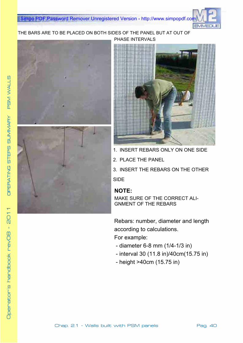
THE BARS ARE TO BE PLACED ON BOTH SIDES OF THE PANEL BUT AT OUT OF PHASE INTERVALS
1. INSERT REBARS ONLY ON ONE SIDE
2. PLACE THE PANEL
3. INSERT THE REBARS ON THE OTHER
SIDE
Rebars: number, diameter and length according to calculations. For example: - diameter 6-8 mm (1/4-1/3 in) - interval 30 (11.8 in)/40cm(15.75 in) - height >40cm (15.75 in)
NOTE:MAKE SURE OF THE CORRECT ALI-GNMENT OF THE REBARS
O
perator’s h
andbook r
ev08 - 2
011
OO
PERATIN
G S
TEPS S
UM
MARY
PSM
WALLS
Simpo PDF Password Remover Unregistered Version - http://www.simpopdf.com

Pag. 41
Operator’s h
andbook r
ev08 - 2
011
Chap.2.1 - Walls built with PSM panels
3.1.2 ASSEMBLING THE PANELS 3.1.2 ASSEMBLING THE PANELS
One may begin from a corner and proceed along both sides paying attention to maintain perpendicularity. If this method is adopted, one has to proceed by completing single rooms.
In case of long walls, another procedure to be used is the following: Begin from a wall and continue by placing perpendicular walls on a frontal advance-ment.
O
perator’s h
andbook r
ev08 - 2
011
OO
PERATIN
G S
TEPS S
UM
MARY
PSM
WALLS
Simpo PDF Password Remover Unregistered Version - http://www.simpopdf.com

Pag. 42 Chap. 2.1 - Walls built with PSM panels
Operator’s h
andbook r
ev08 - 2
011
CONNECTING PANELS ON THE REBARS
CUTS: In order to perform cuts according to the panel layout, one may use instruments like bolt cutters or angle grinders.
O
perator’s h
andbook r
ev08 - 2
011
OO
PERATIN
G S
TEPS S
UM
MARY
PSM
WALLS
Simpo PDF Password Remover Unregistered Version - http://www.simpopdf.com

Pag. 43
Operator’s h
andbook r
ev08 - 2
011
Chap.2.1 - Walls built with PSM panels
CONNECTING ADJACENT PANELS
Pneumatic stapler
Preliminary bond One every meter
Bonding with stitiche: 1 every 4 stitches.
Before applying the stitches, make sure that the panels fit per-fectly.
It is possible to pre-assemble more consecutive panels and place them all together.
O
perator’s h
andbook r
ev08 - 2
011
OO
PERATIN
G S
TEPS S
UM
MARY
PSM
WALLS
Simpo PDF Password Remover Unregistered Version - http://www.simpopdf.com

Pag. 44 Chap. 2.1 - Walls built with PSM panels
Operator’s h
andbook r
ev08 - 2
011
PLACING REINFORCEMENT MESHES
WALL HORIZONTAL SECTIONS
O
perator’s h
andbook r
ev08 - 2
011
OO
PERATIN
G S
TEPS S
UM
MARY
PSM
WALLS
Simpo PDF Password Remover Unregistered Version - http://www.simpopdf.com

Pag. 45
Operator’s h
andbook r
ev08 - 2
011
Chap.2.1 - Walls built with PSM panels
VARIOUS TYPES OF MANUAL STA-PLERS
PLACING REINFOR-CEMENT MESHES
O
perator’s h
andbook r
ev08 - 2
011
OO
PERATIN
G S
TEPS S
UM
MARY
PSM
WALLS
Simpo PDF Password Remover Unregistered Version - http://www.simpopdf.com

Pag. 46 Chap. 2.1 - Walls built with PSM panels
Operator’s h
andbook r
ev08 - 2
011
3.1.33.1.3 PLUMBINGPLUMBING ANDAND SCAFFOLDINGSCAFFOLDING OFOF WALLSWALLS
Before scaffolding the walls,Make sure they are plumbed.
1 scaffold every 3 me-ters(9 ft)
It is adviseable to scaffold on the internal side with conventional construction equipment
Scaffold stretcher
O
perator’s h
andbook r
ev08 - 2
011
OO
PERATIN
G S
TEPS S
UM
MARY
PSM
WALLS
Simpo PDF Password Remover Unregistered Version - http://www.simpopdf.com

Pag. 47
Operator’s h
andbook r
ev08 - 2
011
Chap.2.1 - Walls built with PSM panels
3.1.43.1.4 PLACINGPLACING COUNTERFRAMESCOUNTERFRAMES FORFOR DOORDOOR ANDAND WINDOWSWINDOWS
PLACING FLAT MESHES
In case of external doors, leave at least 4 cm (1.6 in) of polystyrene to avoid thermal bridges.
Locally remove polystyrene to an-chor counterframe
Place flat meshes at 45°, at a distance of less than 1 cm (0.4 in.) from the opening’s edge
DOORS
Flat mesh at 45°
O
perator’s h
andbook r
ev08 - 2
011
OO
PERATIN
G S
TEPS S
UM
MARY
PSM
WALLS
Simpo PDF Password Remover Unregistered Version - http://www.simpopdf.com

Pag. 48 Chap. 2.1 - Walls built with PSM panels
Operator’s h
andbook r
ev08 - 2
011
WINDOWS
Leave at least 4 cm (1.6 in) of pol-ystyrene to avoid thermal bridges.
Flat mesh at 45°
O
perator’s h
andbook r
ev08 - 2
011
OO
PERATIN
G S
TEPS S
UM
MARY
PSM
WALLS
Simpo PDF Password Remover Unregistered Version - http://www.simpopdf.com

Pag. 49
Operator’s h
andbook r
ev08 - 2
011
Chap.2.1 - Walls built with PSM panels
The polystyrene should be melted by a hot air jet.
3.1.53.1.5 INSERTINGINSERTING INSTALLATION’SINSTALLATION’S CHANELSCHANELS
After that, the positioning of the chanels may take place.
When it is necessary to cut out the mesh, a restoration is in order with a flat mesh,after inserting the chanels.
Restoration with a flat mesh
O
perator’s h
andbook r
ev08 - 2
011
OO
PERATIN
G S
TEPS S
UM
MARY
PSM
WALLS
Simpo PDF Password Remover Unregistered Version - http://www.simpopdf.com

Pag. 50 Chap.2.2 - Application shotcrete
Operator’s h
andbook r
ev08 - 2
011
3.2.13.2.1 BEFOREBEFORE THETHE SHOTCRETESHOTCRETE APPLICATIONAPPLICATION
By placing the scaffolds on the internal side, it is possible to rapidly apply the shotcrete on the external side.
Do not forget to place reinforcement meshes before applying shotcrete.
O
perator’s h
andbook r
ev08 - 2
011
OO
PERATIN
G S
TEPS S
UM
MARY
SHOTCRETE
CHAPTER 3.1 CHAPTER 3.1 SHOTCRETE APPLICATION SHOTCRETE APPLICATION
Verify correct alignment of walls
NOTE:Remember that the plumbing of walls is ab-solutely necessary.
Simpo PDF Password Remover Unregistered Version - http://www.simpopdf.com

Pag. 51
Operator’s h
andbook r
ev08 - 2
011
Chap.2.2 - Application shotcrete
Place screed rails at intervals of 1,5 meters (5 ft).
3.2.23.2.2 POSITIONINGPOSITIONING OFOF SCREEDSSCREEDS
Screed rails Screed rails made with plaster
O
perator’s h
andbook r
ev08 - 2
011
OO
PERATIN
G S
TEPS S
UM
MARY
SHOTCRETE
Screed rails
Simpo PDF Password Remover Unregistered Version - http://www.simpopdf.com

Pag. 52 Chap.2.2 - Application shotcrete
Operator’s h
andbook r
ev08 - 2
011
3.2.3 SHOTCRETE3.2.3 SHOTCRETE
The shotcrete to be applied may be a premixed type or prepared on site. In any case it must have the following characteristics:
SHOTCRETE PREPARED ON SITE PREMIXED SHOTCRETE
Mix Design
�� Portland type cement �� Sand of a diameter 0-6 mm (0-1/4 in) �� CEMENT/SAND(in volume) = 1/4 �� ACQUA/CEMENTO (in weight) < 0,52
TYPE
Eventual admixtures
�� Cement based �� Rck > 25 MPa (3556 PSI)
�� fluidifiers�� Hydro repellers �� Polypropylene fibers
The shotcrete should be applied on the walls in two consecutive layers, the first of which, will be sufficient to cover the steel mesh.
Use of a Turbosol type pump Use of M2 renderer
O
perator’s h
andbook r
ev08 - 2
011
OO
PERATIN
G S
TEPS S
UM
MARY
SHOTCRETE
Simpo PDF Password Remover Unregistered Version - http://www.simpopdf.com

Pag. 53
Operator’s h
andbook r
ev08 - 2
011
Chap.2.2 - Application shotcrete
3.2.4 VARIOUS 3.2.4 VARIOUS RECOMMENDATIONSRECOMMENDATIONS
Always start rendering from bottom to top
Leave space between the screed and the pla-ster
OK!!
Not correct
Once the plastering procedure is finished, maintain the walls damp for at le-ast 48 hours and wait for at least 28 days before applying an eventual fini-shing/colouring layer.
O
perator’s h
andbook r
ev08 - 2
011
OO
PERATIN
G S
TEPS S
UM
MARY
SHOTCRETE
Not correct
Simpo PDF Password Remover Unregistered Version - http://www.simpopdf.com

Pag. 54 Chap.2.3 - Walls built with PDM panels
Operator’s h
andbook r
ev08 - 2
011
CHAPTER 3.3CHAPTER 3.3WALLSWALLS BUILTBUILT WITHWITH DOUBLEDOUBLE PANELPANEL
MAINMAIN OPERATINGOPERATING STEPSSTEPS::1. Placing rebars in foundations 2. Assembling of the panels - preliminary step - Initial step - connecting adjacent panels - various additions - Cutting the panels 3. Scaffolding the panels 4. Filling the walls with concrete 5. Placing on site of M2 slab panel 6. Installation and rendering
3.33.3.1.1 PLACINGPLACING REBARSREBARS ININ FOUNDATIONSFOUNDATIONS
The dimensions and reinforcements of the foundations are to be derived from the structural calculations. The smoothness of the surface of the foundations is very important for the correct placement of the panels.
O
perator’s h
andbook r
ev08 - 2
011
OO
PERATIN
G S
TEPS S
UM
MARY
PDM
WALLS
Simpo PDF Password Remover Unregistered Version - http://www.simpopdf.com

Pag. 55
Operator’s h
andbook r
ev08 - 2
011
Chap.2.3 - Walls built with PDM panels
The anchorage rebars must have the following characteristics:
�� Filleted U type to better enable the panel insertion
�� Diameter from structural calcula-tions
�� Height from structural calcula-tions
�� Intervals from structural calcula-tions
�� Width equal to concrete wall width minus 5 cm.(2 in)
Verify the correct alignment of the rebars that has to have a tollerance of +/-1cm (0.4 in). Eventual errors of alignment could cause difficulty in placing the panels.
Lay the tracks of at least one of the external perimeters of the panel on the foundations plane.
Screed boards
3.33.3.2.2 ASSEMBLINGASSEMBLING THETHE PANELSPANELS
PRELIMINARY FASE
O
perator’s h
andbook r
ev08 - 2
011
OO
PERATIN
G S
TEPS S
UM
MARY
PDM
WALLS
The width measured externally has to be non greater than the concrete wall width minus 5 cm (2 in).
Simpo PDF Password Remover Unregistered Version - http://www.simpopdf.com

Pag. 56 Chap.2.3 - Walls built with PDM panels
Operator’s h
andbook r
ev08 - 2
011
INITIAL PHASE Begin assembling the panels starting prefera-bly from a corner. Once the corner panels 1 and 2 are in place (cuts should be made on the panels), pro-ceed by placing panel 3.
Panel 1
Panel 2
Panel 3
At this point the additional reinforce-ments (the part supplied by the manu-facturer) are inserted in order to connect panel 3 with panel 1
Panel 3
Make sure from the start that the panels are aligned and plumbed.
Caution: Insert eventual vertical additional reinforcements according to structural calculations.
O
perator’s h
andbook r
ev08 - 2
011
OO
PERATIN
G S
TEPS S
UM
MARY
PDM
WALLS
Simpo PDF Password Remover Unregistered Version - http://www.simpopdf.com

Pag. 57
Operator’s h
andbook r
ev08 - 2
011
Chap.2.3 - Walls built with PDM panels
3.33.3..33 CONNECTINGCONNECTING ADJACENTADJACENT PANELSPANELS
Bond 1/ml
Next, connect the panels with 1 stitch every 4 meshes, using manual or pneumatic staplers.
For the correct placement of the panels, refer to the panel layout supplied by Emmedue’s techni-cal staff.
Place scaffolds on the walls to counter the action of the wind
First connect the panels using wire, making it so that the bonds correspond to connec-tors.
O
perator’s h
andbook r
ev08 - 2
011
OO
PERATIN
G S
TEPS S
UM
MARY
PDM
WALLS
Simpo PDF Password Remover Unregistered Version - http://www.simpopdf.com

Pag. 58 Chap.2.3 - Walls built with PDM panels
Operator’s h
andbook r
ev08 - 2
011
3.33.3..44 VARIOUSVARIOUS ADDITIONSADDITIONS
Angular me-shes and ad-ditional rein-forcements(supplied by panel manu-facturer)
Insert connection reinforcements (supplied by panel manufacturer) and vertical 2Ø16 reinforcements corresponding to every intersection and corner. Place flat meshes at 45° at the edges of openings and angular meshes at the corners and crossings.
Flat meshes
O
perator’s h
andbook r
ev08 - 2
011
OO
PERATIN
G S
TEPS S
UM
MARY
PDM
WALLS
Simpo PDF Password Remover Unregistered Version - http://www.simpopdf.com

Pag. 59
Operator’s h
andbook r
ev08 - 2
011
Chap.2.3 - Walls built with PDM panels
3.33.3..55 CUTTINGCUTTING THETHE PANELSPANELS
To perform eventual cuts according to the panel layout one may use angle grinders with appropriate discs to cut through the steel.
CORNER CONSTRUCTION PHASE
INTERSECTION CONSTRUCTION PHASE�� Cut of the internal panel plates and of the internal Ø5 mm mesh.
�� Assembling of the panels. �� Connection through angular me-
shes.
�� Cutting the polystyrene plates �� Assembling of the panels �� Connection through angular me-
shes
Size of plate cut: Width of concrete pla-te+thickness of EPS
Size of plate cut: Width of perpendicu-lar concrete plate.
O
perator’s h
andbook r
ev08 - 2
011
OO
PERATIN
G S
TEPS S
UM
MARY
PDM
WALLS
Simpo PDF Password Remover Unregistered Version - http://www.simpopdf.com

Pag. 60 Chap.2.3 - Walls built with PDM panels
Operator’s h
andbook r
ev08 - 2
011
3.33.3..66 PLUMBINGPLUMBING ANDAND SCAFFOLDINGSCAFFOLDING THETHE WALLSWALLS
1. Control the perfect plumbing of the walls
2. Position supporting components for the casting phase
3. Place scaffolds for the walls
In order to reduce thermal bridges, one may cover all opening’s perimeter with polystyrene plates of 2-3 cm (0.8-1.2 in) thickness.Such plates, if rendered, should be co-vered by meshes. In any case, before the casting, always prepare frames for conventional sealing.
Frame to seal the openings
O
perator’s h
andbook r
ev08 - 2
011
OO
PERATIN
G S
TEPS S
UM
MARY
PDM
WALLS
Simpo PDF Password Remover Unregistered Version - http://www.simpopdf.com

Pag. 61
Operator’s h
andbook r
ev08 - 2
011
Chap.2.3 - Walls built with PDM panels
3.33.3..77 FILLINGFILLING THETHE WALLWALL PANELSPANELS WITHWITH CONCRETECONCRETE
In order to facilitate the filling opera-tion and avoid concrete segregation, it is advisable to use a casting tube of adequate size.
The recommended characteristics of the concrete are the following:
�� Maximum diameter of 12 mm �� workability S5 �� Rck > 25 MPa (3556 PSI)
The casting should be interrupted at 30 cm (11.8 in) below the ceiling level, in order to secure the anchorage of the rebars.
3.33.3..88 INSTALLATIONSINSTALLATIONS ANDAND RENDERINGRENDERING
Regarding the installations, refer to chapters 3.1 and 3.2 of the present ma-nual.
O
perator’s h
andbook r
ev08 - 2
011
OO
PERATIN
G S
TEPS S
UM
MARY
PDM
WALLS
Simpo PDF Password Remover Unregistered Version - http://www.simpopdf.com

Pag. 62 Chap.2.4 - Floors built with PSS1 panels
Operator’s h
andbook r
ev08 - 2
011
3.4.13.4.1 INSTALLINGINSTALLING PSSPSS11 SINGLESINGLE PANELPANEL SLABSLAB
CHAPTER 3.4CHAPTER 3.4SLABSSLABS BUILTBUILT WITHWITH PSSPSS11 SINGLESINGLE PANELPANEL
O
perator’s h
andbook r
ev08 - 2
011
OO
PERATIN
G S
TEPS S
UM
MARY
PSS1 S
LABS
The slab is connected to the walls through steel bars and/or reinforcement meshes.
The installation of the PSS1 panel is similar to that of the sin-gle panel.
Simpo PDF Password Remover Unregistered Version - http://www.simpopdf.com

Pag. 63
Operator’s h
andbook r
ev08 - 2
011
Chap.2.4 - Floors built with PSS1 panels
O
perator’s h
andbook r
ev08 - 2
011
OO
PERATIN
G S
TEPS S
UM
MARY
PSS1 S
LABS
Place the panels on props placed at intervals of 60 cm (23.6 in).
Walk exclusively on wooden bridge boards laying on the post
Simpo PDF Password Remover Unregistered Version - http://www.simpopdf.com

Pag. 64 Chap.2.5 - Floors built with PSSG panels
Operator’s h
andbook r
ev08 - 2
011
3.5.13.5.1 INSTALLINGINSTALLING THETHE PSSGPSSG SLABSSLABS
When using panels with steel reinforcements to enhance self support, place the interruption components at intervals of 1,2 m(3.9 in).
CHAPTERCHAPTER 3.5 3.5SLABSSLABS BUILTBUILT WITHWITH PSSGPSSG PANELPANEL
O
perator’s h
andbook r
ev08 - 2
011
OO
PERATIN
G S
TEPS S
UM
MARY
PSS1 S
LABS
Simpo PDF Password Remover Unregistered Version - http://www.simpopdf.com

Pag. 65
Operator’s h
andbook r
ev08 - 2
011
Chap.2.5 - Floors built with PSSG panels
3.5.23.5.2 INSTALLING M2 INSTALLING M2 SLABSLAB PANELPANEL
For the correct positioning of the panels refer to the panel layout supplied by the Emmedue technical staff.
Place the slab on the internal plate of double panel, unless a reinforced stripe is required by the structural calculation.
It is recommended to use omega shaped steel bars in order to ensure the neces-sary covering for the rein-forcements
Before casting the slab concrete, place the wall rebars.
O
perator’s h
andbook r
ev08 - 2
011
OO
PERATIN
G S
TEPS S
UM
MARY
PSSG S
LABS
Simpo PDF Password Remover Unregistered Version - http://www.simpopdf.com

Pag. 66 Chap.2.5 - Floors built with PSSG panels
Operator’s h
andbook r
ev08 - 2
011
3.5.33.5.3 COMPLETINGCOMPLETING MM22 SLABSSLABS
Insert an EPS stripe to ensure the homogeneity of thermal insulation.
O
perator’s h
andbook r
ev08 - 2
011
OO
PERATIN
G S
TEPS S
UM
MARY
PSSG S
LABS
Reinforcement rebars for the upper level walls.
Slab completion by casting the concrete.
Insert joist reinforce-ments according to structural calculations. NOTE: Place appro-priate supports in cor-respondance of beams and/or slab interrup-tions.
Simpo PDF Password Remover Unregistered Version - http://www.simpopdf.com

Simpo PDF Password Remover Unregistered Version - http://www.simpopdf.com

Pag. 67
Operator’s h
andbook r
ev08 - 2
011
Chap.2.6 - Stairs, landings and balconies
Beam to be reinforced and cast on site
Before installing the staircase panel, insert adequate reinforcements in each beam.
CHAPTERCHAPTER 3.6 3.6STAIRCASES, STAIRCASES, LANDINGSLANDINGS ANDAND BALCONIESBALCONIES
O
perator’s h
andbook r
ev08 - 2
011
OOPERATIN
G S
TEPS S
UM
MARY
PSSC S
TAIR
CASE
Simpo PDF Password Remover Unregistered Version - http://www.simpopdf.com

Pag. 68 Chap.2.6 - Stairs, landings and balconies
Operator’s h
andbook r
ev08 - 2
011
Before casting place slab interrup-tion components at intervals of 1 meter (3.3 ft).
Complete by applying cement based plaster.
O
perator’s h
andbook r
ev08 - 2
011
OOPERATIN
G S
TEPS S
UM
MARY
PSSC S
TAIR
CASE
,
Simpo PDF Password Remover Unregistered Version - http://www.simpopdf.com

Pag. 69
Operator’s h
andbook r
ev08 - 2
011
Chap.2.7- Claddings and partitions built with PST panels
CHAPTERCHAPTER 3.7 3.7
CLADDINGCLADDING ANDAND PARTITIONPARTITION WALLSWALLSFor the installation of cladding and partitioning panels, apply the same indica-tions provided for the PSM single panel.
EXAMPLE OF CLADDING ANCHORAGE: Supporting panel and insertion of dry wall component.
O
perator’s h
andbook r
ev08 - 2
011
OO
PERATIN
G S
TEPS S
UM
MARY
PSST
Simpo PDF Password Remover Unregistered Version - http://www.simpopdf.com

Pag. 70 Chap.2.7- Claddings and partitions built with PST panels
Operator’s h
andbook r
ev08 - 2
011
O
perator’s h
andbook r
ev08 - 2
011
OO
PERATIN
G S
TEPS S
UM
MARY
PSST
The panels will be appropriately an-chored on the supporting structure:
Through welded steel bars Through anchored steel bars and lesser C steel section.
Through L shaped steel plate.
Simpo PDF Password Remover Unregistered Version - http://www.simpopdf.com

Pag. 71
Operator’s h
andbook r
ev08 - 2
011
Chap.2.8 - Cladding coat built with PST-C panel
CHAPTERCHAPTER 3.8 3.8INSULATING INSULATING COVERSCOVERS WITHWITH PST PST--CC PANELPANEL
3.8.13.8.1 MAINMAIN APPLICATIONAPPLICATION PHASESPHASES::Phase 1: Applying the adhesive mortar on the panel The mortar should be layed in stripes along the perimeter and in spots in the central area. Avoid applying excessive quantities of mortar on the borders that could create problems in fitting together the panels.
Phase 2: Placing the panels Make sure of the perfect fitting of the pa-nels and proceed by binding together the overlapping meshes at intervals of one bond every four stitches along the verti-cal direction of the mesh.
Phase 3: Application of the mechani-cal fixing. Before the hardening of the adhesive mortar starts, proceed by applying the appropriate anchorings in the form of steel nails with plastic discs. The number of anchorings should be 5 for every sqm. The depth of anchoring on the support should be at 5 cm (2 in). (see pic.2 and 3)
Phase 4: Placing additional meshes Flat meshes at 45° should be placed at all edges. Wherever there is a mesh in-terruption the continuity of the mesh should be restored with stripes of flat me-shes.
Picture 2 Picture 3
O
perator’s h
andbook r
ev08 - 2
011
OO
PERATIN
G S
TEPS S
UM
MARY
INSULATIN
G C
OVERS
Picture 1
Simpo PDF Password Remover Unregistered Version - http://www.simpopdf.com

Pag. 72 Chap.2.8 - Cladding coat built with PST-C panel
Operator’s h
andbook r
ev08 - 2
011
Phase 5: Plaster application Proceed by applying the first layer of plaster with a screed pump. The la-yer thickness should be enough to cover the mesh. Once the necessary hardening time has passed, proceed by applying the second layer in order to achieve a to-tal thickness of 2 cm (0.78 in).( See pic. 4)
Phase 6: Applying the finishing la-yer. Once the curing of the plaster is complete, proceed by applying a final thin smoothing layer.
Figura 4
O
perator’s h
andbook r
ev08 - 2
011
OO
PERATIN
G S
TEPS S
UM
MARY
INSULATIN
G C
OVERS
Simpo PDF Password Remover Unregistered Version - http://www.simpopdf.com

Simpo PDF Password Remover Unregistered Version - http://www.simpopdf.com

PART 3:PART 3:
CONSTRUCTION DETAILS CONSTRUCTION DETAILS
Operator’s handbook rev08 Operator’s handbook rev08 Operator’s handbook rev08 --- 2011 2011 2011
Simpo PDF Password Remover Unregistered Version - http://www.simpopdf.com

Simpo PDF Password Remover Unregistered Version - http://www.simpopdf.com

Simpo PDF Password Remover Unregistered Version - http://www.simpopdf.com

Simpo PDF Password Remover Unregistered Version - http://www.simpopdf.com

Simpo PDF Password Remover Unregistered Version - http://www.simpopdf.com

Simpo PDF Password Remover Unregistered Version - http://www.simpopdf.com

Simpo PDF Password Remover Unregistered Version - http://www.simpopdf.com

Simpo PDF Password Remover Unregistered Version - http://www.simpopdf.com

Simpo PDF Password Remover Unregistered Version - http://www.simpopdf.com

Simpo PDF Password Remover Unregistered Version - http://www.simpopdf.com

Simpo PDF Password Remover Unregistered Version - http://www.simpopdf.com

Simpo PDF Password Remover Unregistered Version - http://www.simpopdf.com

Simpo PDF Password Remover Unregistered Version - http://www.simpopdf.com

ANCHORAGE ON SLAB FOUNDATION
ANCHORAGE ON SLAB FOUNDATION
d
Simpo PDF Password Remover Unregistered Version - http://www.simpopdf.com

ANCHORAGE ON STRIP FOUNDATION
ANCHORAGE ON STRIP FOUNDATION
Simpo PDF Password Remover Unregistered Version - http://www.simpopdf.com

H1
concrete Rbk 15 N/mmq
big dimensionwashed gravel
geotexture concrete slab
1+1Ø
14/2
5
basement wall
1Ø14
/25
insulating layer
drainage
rain water collection tube
Simpo PDF Password Remover Unregistered Version - http://www.simpopdf.com

S
var.VAR.var.25
st.ø5/25var.
RG1
2ø16
st.ø
5/25
var.
var. 25var.25 VAR.
RG1
RG1RG1
st.ø
5/25
2ø16
25
var.
Simpo PDF Password Remover Unregistered Version - http://www.simpopdf.com

1Ø 8
/30
L=23
0
SLABPLASTER
st. ø8/304 Ø12
L =3
0 cm
L =
50
cmd
PSSG
H
LIMIT POINT OF CASTINGPhase 1
Simpo PDF Password Remover Unregistered Version - http://www.simpopdf.com

L =3
0 cm
Lmin
= 5
0 cm PDM
1Ø 8
/30
L=23
0
st. ø8/304 Ø12
d
DETAIL EXTERIOR SLAB ANCHORING
LIMIT POINT OF CASTINGPhase 1
SLABPSSG
PLASTER
DETAIL EXTERIOR SLAB ANCHORING
ESimpo PDF Password Remover Unregistered Version - http://www.simpopdf.com

Simpo PDF Password Remover Unregistered Version - http://www.simpopdf.com

Simpo PDF Password Remover Unregistered Version - http://www.simpopdf.com

Section Z-Zscale 1:10
1+1ø8(1+1ø12
if L>200cm)
1+1ø
8/30
L=2
60
2+2ø12st.ø8/30
L
LINTEL OVER DOOR AND WINDOW
LINTEL OVER DOOR AND WINDOW
L =3
0 cm
Lmin
= 5
0 cm
PLASTER
PDM
1Ø 8
/30
L=23
0
st. ø8/304 Ø12
LIMIT POINT OF CASTINGPhase 1
d
SLABPSSG
Simpo PDF Password Remover Unregistered Version - http://www.simpopdf.com

30
MSimpo PDF Password Remover Unregistered Version - http://www.simpopdf.com

30
PSSG ROOFTOP
FSimpo PDF Password Remover Unregistered Version - http://www.simpopdf.com

st.Ø5/20
low. 2 Ø10/joist
upp. 1 Ø10/joist
LANDING h=18 cmrip. 1+2Ø10/joist
1Ø10/joist
2Ø10/joist
Anchoring staircase with landing
Anchoring staircase with foundationsstaircase panel
st.Ø5/20
low. 2 Ø10/joistupp. 1 Ø10/joist
polystyrene density 15Kg/mcelectrowelded mesh
reinforcements and casting to
SECTION EMMEDUE STAIRCASE
be completed on site
SECTION EMMEDUE STAIRCASE
1Ø10/joist
2Ø10/joist
P
O
Simpo PDF Password Remover Unregistered Version - http://www.simpopdf.com

Pag. 74 Chap. 2.1 - Walls built with PSM panels
Operator’s h
andbook r
ev08 - 2
011
Simpo PDF Password Remover Unregistered Version - http://www.simpopdf.com