manual - · pdf file1.4.5 tcc (terminal control computer) ... serial communication with the...
TRANSCRIPT
© DESIGNA Verkehrsleittechnik GmbHSubject to technical modification without prior notice
Manual
System PM100
Automatic Pay StationAPS 100 COMPACT
Ticket / CHIPMASTER
Version 1.20


AKS 100 COMPACT Structure of the pay station
DESIGNA Verkehrsleittechnik GmbH page 3
Contents
1 Structure of the pay station..................................................................................51.1 Overview ........................................................................................................51.2 Housing..........................................................................................................51.3 Control elements at the door........................................................................6
1.3.1 Buttons ........................................................................................................................... 61.3.2 Display............................................................................................................................ 6
1.4 Inner structure of the pay station.................................................................71.4.1 Main switch..................................................................................................................... 71.4.2 Power component 24 V.................................................................................................. 71.4.3 Multicon.......................................................................................................................... 81.4.4 The Chipmaster unit (CME) ......................................................................................... 111.4.5 TCC (Terminal Control Computer)............................................................................... 131.4.6 Coin processing unit MVE............................................................................................ 151.4.7 Note processing ........................................................................................................... 171.4.8 Receipt printer .............................................................................................................. 181.4.9 Unit heating .................................................................................................................. 19
2 Technical data .....................................................................................................20
3 Functioning of the pay station ...........................................................................21
4 Erection of the pay station .................................................................................224.1 Wall mounting .............................................................................................224.2 Erection with stand .....................................................................................234.3 Connections of the APS 100 COMPACT ....................................................24
4.3.1 Power supply................................................................................................................ 244.3.2 Connection up the intercom ......................................................................................... 244.3.3 DESINET connection ................................................................................................... 25
5 Initial commissioning..........................................................................................255.1 First check of the pay station.....................................................................255.2 Function test................................................................................................25
6 Maintenance.........................................................................................................266.1 Daily care and checks.................................................................................266.2 Monthly maintenance..................................................................................276.3 Quarterly maintenance................................................................................276.4 Replace the ribbon cassette of the ticket printer (ticket systems only)..28
7 Appendix ..............................................................................................................297.1 Payment possibilities..................................................................................29
7.1.1 Cash payment .............................................................................................................. 297.1.2 ec-/credit cards for payment (optional)......................................................................... 297.1.3 Electronic purse (optional) ........................................................................................... 297.1.4 Discounting (ticket punch, discounter) (optional) ......................................................... 29
7.2 Special features...........................................................................................307.2.1 Language synthesiser .................................................................................................. 30
7.3 Payment unit................................................................................................31

Structure of the pay station APS 100 COMPACT
page 4 © DESIGNA Verkehrsleittechnik GmbH
Overview of versions
Version 1.0 03.06.1998 JB, Eh Compilation of the documentVersion 1.1 10.03.1999. Ba Revision, new housingVersion 1.2 30.10.1999- Ba Revision, new printer

AKS 100 COMPACT Structure of the pay station
DESIGNA Verkehrsleittechnik GmbH page 5
1 Structure of the pay station
1.1 OverviewThe automatic pay station APS 0100 COMPACT is available for two different systems: for ticketsystems for processing parking tickets with magnetic strips, and for the Chipmaster system,which uses parking chips. The systems differ only in the way the tickets or chips are processed.For this reason, the manual refers to tickets and parking chips.
Illustration 1: Complete overview of the COMPACT pay station
1.2 HousingThe housing is made from elo-galvanised sheet steel, the door consists of stainless steel. Thestandard version of the unit is powder coated in Pantone 320C (turquoise blue). Other coatingsare possible as options. The components required to operate the unit are mounted on a frame.
In the basic version, the pay station is supplied without stand and without lighting unit. Amounting kit is required for wall mounting. If required by the customer, a stand and/or a lightingunit over the pay station can also be fitted.
The front door is double locked with a bar lock. The bar lock is secured by means of a securitycylinder lock.
Structure of the pay station APS 100 COMPACT
page 6 © DESIGNA Verkehrsleittechnik GmbH
1.3 Control elements at the door1.3.1 Buttons
The control elements are mounted in the middle of the pay station housing. The buttons havethe following function:
• Cancellation buttonThe cancellation button interrupts the current pay station procedure. The pay station paysback any paid money, or codes a credit note on the ticket/card/chip and returns theticket/card/chip.
• Information buttonThe information button forms a link to the intercom centre and makes a call tone be heardin the main intercom centre.
• Receipt buttonBy pressing the receipt button, the customer can obtain a receipt of the paid parking feeafter completing payment.A receipt is produced automatically for payment by credit card or when a paid ticket is in-serted into the magnetic card reader a second time.
Optional:
• Language switchThis button can be used to change the language used in the display. The possible lan-guages are indicated by the flags next to the button. The language texts are downloadedfrom the BFR by pressing the button, and are then shown in the display. The system canmanage up to 4 languages.
Optional for ticket systems:
• Lost ticketWith this button, the customer can request a replacement ticket at a special rate (normallythe daily rate). This button can be blocked or released from the data control centre to ruleout any risk of misuse, for example this button can be released for individual customersafter checking the situation by means of the intercom.
1.3.2 Display
A liquid crystal display (LCD) 2 x 20 characters is integrated in the pay station. The charactersare 10 mm high. The display is illuminated from behind by LEDs. All instructions necessary foroperation (user guide, money amounts, fault messages) are shown in plain text.As an option, a display with space for 4 x 20 characters is available, which indicates the sumsof money in the local currency and Euro.
Illuminated arrows help the car park customer through all transactions at the automatic paystation.

AKS 100 COMPACT Structure of the pay station
DESIGNA Verkehrsleittechnik GmbH page 7
1.4 Inner structure of the pay stationThe inner structure of the pay station is arranged in three areas. On the left, depending on thesystem, there is the magnetic card reader or parking chip reader. The control electronic (->TCC) is fastened on a mounting plate together with the power supply and the connection termi-nals. In the middle is the coin processing unit and right on the right the receipt printer, togetherwith the options note processing and money card reader.The individual components of the pay station are described below.
1.4.1 Main switch
The main switch is located in the rear left-hand section of the pay station. This switch is used toswitch the pay station on and off. In the lower position, the switch disconnects the pay stationfrom the power mains for all poles. When this switch is switched on, the pay station is suppliedwith electricity and the TCC loads its program.
CAUTION:The mains filter, terminal strip and optional illumination unit are not disconnected fromthe mains!
Illustration 2: Main switch and terminal strip
1.4.2 Power component 24 V
The power component is located towards the back, over the main switch. It provides the func-tion modules of the pay station with 24 V DC power supply. An illuminated display (power) indi-cates that the power component is working.The DC power supply is distributed to the modules via the terminal strip positioned under thepower component.
Power component
Thermostat
Main switch
Structure of the pay station APS 100 COMPACT
page 8 © DESIGNA Verkehrsleittechnik GmbH
Depending on the version, a magnetic card reader or parking chip reader is installed inthe pay station.
1.4.3 Multicon
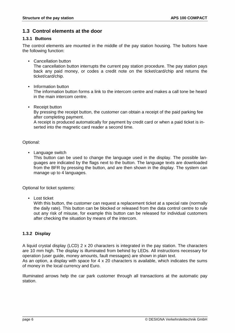
The magnetic card read is used together with the ticket slide or with the options ticket printerand/or transport component, and is called Multicon.Depending on the scope of functions, the magnetic card reader can be equipped optionally withadditional reading heads for the side track as per ISO and for the special track for discounting.
llustration 3: magnetic track reader
1.4.3.1 Magnetic card readerThe magnetic card reader pulls the tickets and cards in, reads the data, writes (codes) the databack on the ticket or card in changed form and then returns the card if required.
Depending on the design of the Multicon, paper tickets can be processed together with plasticcards with middle track and optionally also side track (credit cards, bank and ec cards).
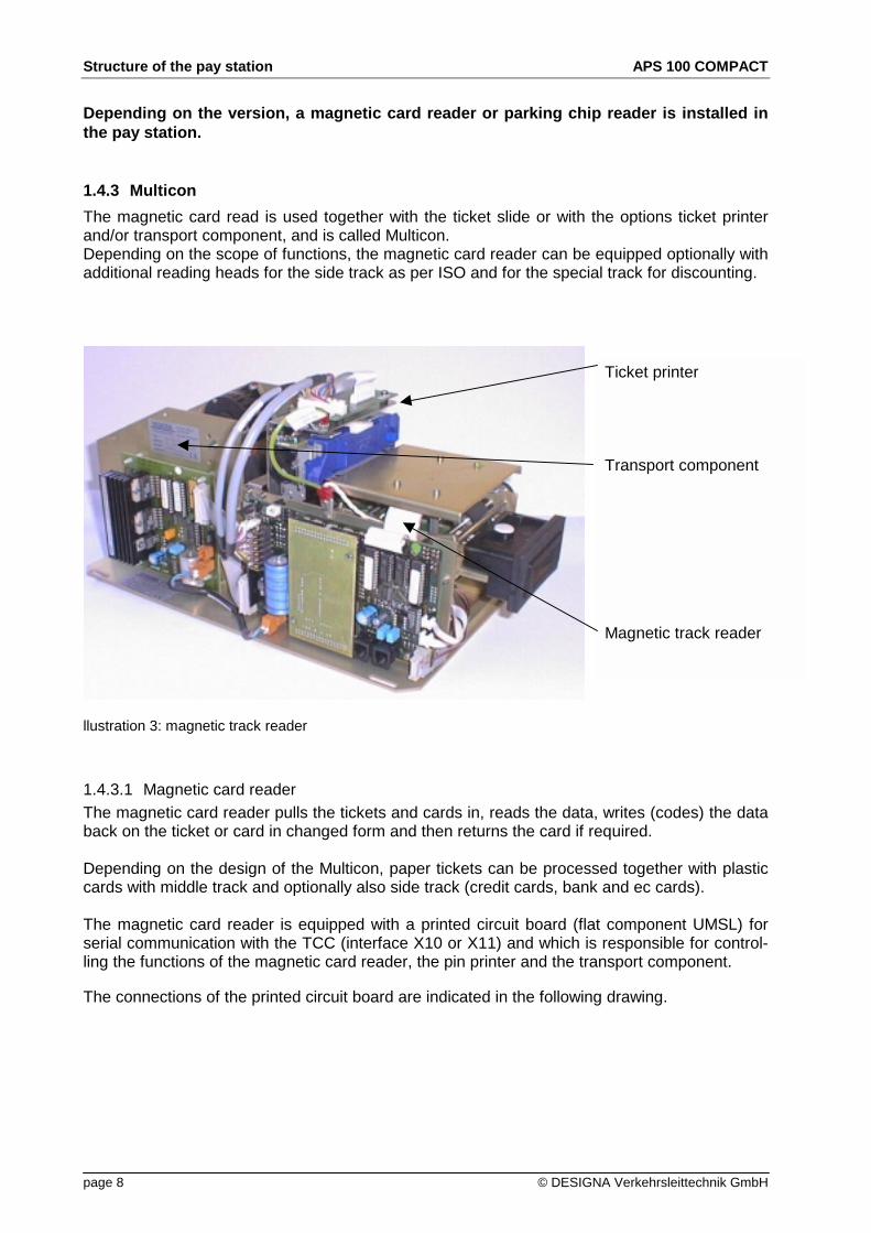
The magnetic card reader is equipped with a printed circuit board (flat component UMSL) forserial communication with the TCC (interface X10 or X11) and which is responsible for control-ling the functions of the magnetic card reader, the pin printer and the transport component.
The connections of the printed circuit board are indicated in the following drawing.
Ticket printer
Transport component
Magnetic track reader
AKS 100 COMPACT Structure of the pay station
DESIGNA Verkehrsleittechnik GmbH page 9
serial Port
not used
light barriersending
light barrierrecieving
motor
Testiicket
Printer
TBG
power LED not used connection pre-amplifier
Illustration 4: Flat component magnetic card reader (UMSL)
1.4.3.2 Ticket printerThe paper tickets (cardboard) are printed in plain text with figures 0 – 9 and capital letters. Thepin printer can only be used in combination with a magnetic card reader, as this controls thetransport of the ticket into the correct printing position.
1.4.3.3 Transport component (TBG) (optional)Three different transport components can be used optionally:
• Transport component TBG I offers the possibility of ticket supply, it is present when the paystation has the option "lost ticket". TBG 1 does not allow for processing of credit cards or valuecheques.
• TBG II supports the processing of credit cards, value and time cheques. It has an integratedticket filter so that the tickets can either be transported into a ticket store or, by changing thefilter over, collected in a collector (e.g. value and time cheques). If the ticket is "parked" in theticket store, then the magnetic reader is free to process a credit card or ec card.
• TBG III has the same features as TBG II but also allows for the additional production oftickets from a belt (lost ticket). However, the processing of value and time checks and the op-tion "lost ticket" are mutually exclusive.
The connections of the printed circuit board in TBG III are shown in the following illustration:

Structure of the pay station APS 100 COMPACT
page 10 © DESIGNA Verkehrsleittechnik GmbH
UMSL main circuit board
24 V DC (main pcb)
Illustration 5: flat component UTBG 2 (assembling side)
Illustration 6: flat component UTBG 2 (soldering side)
light barrier bottom
light barrier middle
Light barrier top
endposition flap
blade
motor2
motor1
Flap
AKS 100 COMPACT Structure of the pay station
DESIGNA Verkehrsleittechnik GmbH page 11
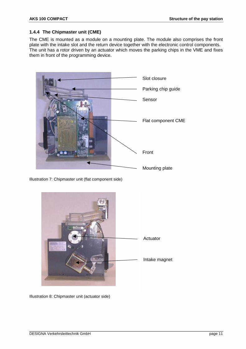
1.4.4 The Chipmaster unit (CME)
The CME is mounted as a module on a mounting plate. The module also comprises the frontplate with the intake slot and the return device together with the electronic control components.The unit has a rotor driven by an actuator which moves the parking chips in the VME and fixesthem in front of the programming device.
Illustration 7: Chipmaster unit (flat component side)
Illustration 8: Chipmaster unit (actuator side)
Slot closure
Parking chip guide
Sensor
Flat component CME
Front
Mounting plate
Actuator
Intake magnet
Structure of the pay station APS 100 COMPACT
page 12 © DESIGNA Verkehrsleittechnik GmbH
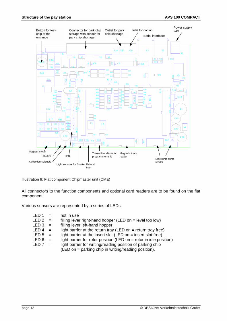
Illustration 9: Flat component Chipmaster unit (CME)
All connectors to the function components and optional card readers are to be found on the flatcomponent.
Various sensors are represented by a series of LEDs:
LED 1 = not in useLED 2 = filling lever right-hand hopper (LED on = level too low)LED 3 = filling lever left-hand hopperLED 4 = light barrier at the return tray (LED on = return tray free)LED 5 = light barrier at the insert slot (LED on = insert slot free)LED 6 = light barrier for rotor position (LED on = rotor in idle position)LED 7 = light barrier for writing/reading position of parking chip
(LED on = parking chip in writing/reading position).
Outlet for parkchip shortage
Stepper motor
shutter
D 17
C 18
R 14
R 5
D 2
D 7
R11
L3
D 9
X1
X17
C 51
R 71
X5
C 46
X2
IC10
X15 X16
C 30C 29
R 36
C43
R 45
D 4
D 5
R17
R 35
R 34
C31
R 39
R16
R9R7
C24
D 10
R 8
C44
D 16D 14
D 12
R 19
D 15
C49
R 18
C52
D 13
C55L1
C38
X6
R 30
X7
C 48
TAST1
R 57
R 44
D 11
X10
R10
IC8
LED
7
F1
C 42
T2
R 43R 70
R38
R 31
D 3
X12
C20
C 22
C 36
X11
R 2
X4X8
X9
R 1
R 13
C 34
R21
IC5
R 67
IC3
LED
1
C 28
R 4
C 25
C26
R22
C 40
C 47
R 24
R 27
R 33
C 37
R 48
L2
R20
C 19
C 27
C39
R 23
Q2
R69
X14
X18
X13
R 32
R 60
R 15
C 33
R 3
IC4
R 68
R 29
R 25
D18
C35
R 26
Q1
R 28
R 59
R 58
R 12
T5
R37
IC12
R 41
IC1
D 6
R 40
R 47
R 46R 42
C 41
R 62
C32
C50
C 54
C23
T1
R 49
R54
R 6
R 55
R 52
R 50
D 8
R 51
R 53
T3T4
IC9
C45
R 64
R 65
R 63
R 61
R 66
IC14
IC7
IC2
IC6
C 53
R 56
IC11
X3
IC13
C21
Button for test-chip at theentrance
Connector for park chipstorage with sensor forpark chip shortage
Inlet for coding
Serial interfaces
Power supply24V
Collection solenoid
Transmitter diode forprogrammer unit
Light sensors for Shutter Refund tray
Magnetic trackreader
Electronic pursereader
LED

AKS 100 COMPACT Structure of the pay station
DESIGNA Verkehrsleittechnik GmbH page 13
1.4.5 TCC (Terminal Control Computer)
The TCC controls all actions inside and outside the Parkmaster 100 units and monitors all func-tions.
1.4.5.1 Technical DesignThe TCC is installed in a sheet steel housing and contains all connectors for the peripheralequipment.The technical data for the TCC (type KCC) are as follows:
Power supply 24V DC
Processor Motorola 68EN302, 20MHz
Memory 2 MB RAM(1 MB Flash RAM for program, 1 MB S-RAM for data)
Data security Integrated Goldcap capacitor for 2-3 days data preservationOptional lithium battery for approx. 1 year data preservation
Serial interfaces 9x RS 232 (including 2 optoelectronic couplers)1x RS 232 for DEBUG1x RS 485 for the car park network DESINETwith integrated, connectable final resistance
Parallel interface 12 inputs and 12 outputs for direct 24V control.The inputs and outputs are 0V active, i.e. in activated state 0V arepresent or must be triggered with0V. The outputs can be loadedwith max. 0.5 A.
Dimensions approx. 250 x 150 x 30 mm
Weight approx. 1000g
Temperature Operation 0 to 50 °CStorage -20 to 70 °C
Structure of the pay station APS 100 COMPACT
page 14 © DESIGNA Verkehrsleittechnik GmbH
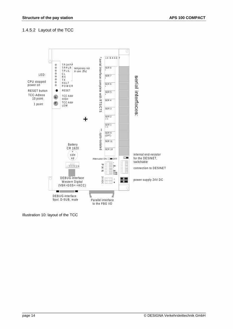
1.4.5.2 Layout of the TCC
Illustration 10: layout of the TCC
1 0 B A S E T
SER 8*
SER 7*
SER 6*
SER 5*
SER 4
SER 3
SER 2* **
SER 1* **
SER 9(OPT)
SER 11
SER 10
*:serial interface complete w
ith RTS
/CTS
**: opto-isolated
T P J A P PT P P L RT P L ILC LR XT XH A L TP O W E R
R ES ET
TC C A ddrH IGHTC C A ddrLO W
+s id eu p
Ba tte ryC R 1620
D E B U G
Attenuator ON OFF
P H
N
-+
24 VD
C
conne ction to D ESIN E T
in te rna l end-res is to rfo r the D E SIN ET, sw itch ab le
pow er supply 24V D C
LE D :
C PU stoppe dpow er o n
R ES ET buttonTC C -Adre ss
10 p oint
1 po in t
D EB U G -in ter face9po l. D -SU B, m ale
D EB U G -in ter faceW es te rn D ig ita l
(VB K=G SS <->KC C )
Pa ralle l in terfaceto th e FBG I/O
tem porary notin use (ffu)

AKS 100 COMPACT Structure of the pay station
DESIGNA Verkehrsleittechnik GmbH page 15
1.4.6 Coin processing unit MVE
Illustration 11: coin processing
The MVE is equipped with a coin tester to test all inserted coins or tokens. The accepted coinsare then sorted into the corresponding hoppers or into the end cassette, and the change is paidout from the intermediate store of the pay station.
The coin tester sends the coins directly to the hoppers via the sorting shaft so that only fourdifferent types of coin can be stored in the hoppers. It is not possible to allocate one type ofcoin to two hoppers.
Coin insert with slot closure
Coin tester
Sorting shaft
Hopper (4x)
Coin filter
Coin end cassette
Structure of the pay station APS 100 COMPACT
page 16 © DESIGNA Verkehrsleittechnik GmbH
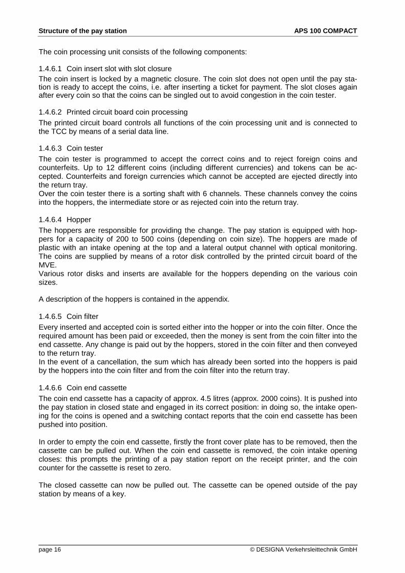
The coin processing unit consists of the following components:
1.4.6.1 Coin insert slot with slot closureThe coin insert is locked by a magnetic closure. The coin slot does not open until the pay sta-tion is ready to accept the coins, i.e. after inserting a ticket for payment. The slot closes againafter every coin so that the coins can be singled out to avoid congestion in the coin tester.
1.4.6.2 Printed circuit board coin processingThe printed circuit board controls all functions of the coin processing unit and is connected tothe TCC by means of a serial data line.
1.4.6.3 Coin testerThe coin tester is programmed to accept the correct coins and to reject foreign coins andcounterfeits. Up to 12 different coins (including different currencies) and tokens can be ac-cepted. Counterfeits and foreign currencies which cannot be accepted are ejected directly intothe return tray.Over the coin tester there is a sorting shaft with 6 channels. These channels convey the coinsinto the hoppers, the intermediate store or as rejected coin into the return tray.
1.4.6.4 HopperThe hoppers are responsible for providing the change. The pay station is equipped with hop-pers for a capacity of 200 to 500 coins (depending on coin size). The hoppers are made ofplastic with an intake opening at the top and a lateral output channel with optical monitoring.The coins are supplied by means of a rotor disk controlled by the printed circuit board of theMVE.Various rotor disks and inserts are available for the hoppers depending on the various coinsizes.
A description of the hoppers is contained in the appendix.
1.4.6.5 Coin filterEvery inserted and accepted coin is sorted either into the hopper or into the coin filter. Once therequired amount has been paid or exceeded, then the money is sent from the coin filter into theend cassette. Any change is paid out by the hoppers, stored in the coin filter and then conveyedto the return tray.In the event of a cancellation, the sum which has already been sorted into the hoppers is paidby the hoppers into the coin filter and from the coin filter into the return tray.
1.4.6.6 Coin end cassetteThe coin end cassette has a capacity of approx. 4.5 litres (approx. 2000 coins). It is pushed intothe pay station in closed state and engaged in its correct position: in doing so, the intake open-ing for the coins is opened and a switching contact reports that the coin end cassette has beenpushed into position.
In order to empty the coin end cassette, firstly the front cover plate has to be removed, then thecassette can be pulled out. When the coin end cassette is removed, the coin intake openingcloses: this prompts the printing of a pay station report on the receipt printer, and the coincounter for the cassette is reset to zero.
The closed cassette can now be pulled out. The cassette can be opened outside of the paystation by means of a key.

AKS 100 COMPACT Structure of the pay station
DESIGNA Verkehrsleittechnik GmbH page 17
After being removed from the automatic pay station, the cassette cannot be pushed backin again immediately, but must be emptied first (i.e. opened and sealed again). Then it ispossible to push the cassette back in again
All individual elements of the coin processing unit can be easily replaced. In addition, the leadcables of all elements are equipped with connectors which facilitate a quick change.
1.4.7 Note processing
Note processing is installed as an option in the right-hand section of the automatic pay station.
The note reader is mounted on a mounting plate. Various readers can be used as required.
1.4.7.1 Note reader BNA
The note reader BNA is available in various versions
BNA 50-X is available with a free-fall storage device for approx. 500 notes, in which the banknotes are collected without being stacked. The "X" stands for a figure which indicates howmany types of notes the reader will take. 2 stands for 4 notes, 3 for 6 notes and 4 for 13 notes.The standard version only accepts one bank note per payment, as it is not possible to return anote once it has been paid into the end cassette. If several notes are to be accepted, this ispossible by means of a "software intermediate store" (software licence); here the notes aretaken immediately into the end cassette. In the case of cancellation of the payment transaction,the value already booked off the ticket is recoded as credit note and subtracted from the park-ing fee at the next payment transaction. It is also possible to limit acceptance of individual banknotes from a certain sum, e.g. a DM 50.00 note can only be used for payment when the fee isDM 30.00 or more.
BNA 51-X is available in the versions of BNA50-X, but in this type the notes are collected in astacking cassette.
BNA 52-X has a stacking cassette and an intermediate storage cassette which can store up to15 notes per payment transaction: in the case of a cancellation, exactly these same notes arethen returned to the customer.
The stacking end cassette of the note reader has a capacity for approx. 1000 notes.
1.4.7.2 Note reader WBA-SS
Note tester WBS-AA can recognise up to 4 notes. The standard version can process one noteper payment transaction. It can also be equipped with a software intermediate storage for ac-ceptance of several bank notes. The standard WBA reader has a locking safety stacking endcassette for approx. 400 notes.

Structure of the pay station APS 100 COMPACT
page 18 © DESIGNA Verkehrsleittechnik GmbH
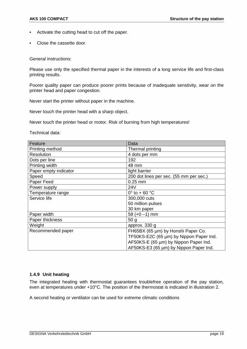
1.4.8 Receipt printer
The thermal printer is used for producing receipts of payment transactions with credit cards orelectronic purses (money card, quick card, etc.) or on request.
Illustration 12: receipt printer
Cutter Threading-in button
The thermal printer has a sensor which detects when there is no more paper, producing a mes-sage to the data control centre. The paper has DESIGNA Ident. number7 232 120 550.
Changing the receipt paper for the thermal printer.
• Open the pay station door.
• Remove the old paper roll, place a new roll on the shaft and set it back in the holder.
• Cut the paper off smoothly and at right angles to the rolling direction.
• Thread the paper into the intake slot until you feel a slight counterpressure.
• Press the thread-in button and the paper is pulled into the printer. Hold this button until thepaper is pushed out of the output slot (in the pay station door).
AKS 100 COMPACT Structure of the pay station
DESIGNA Verkehrsleittechnik GmbH page 19
• Activate the cutting head to cut off the paper.
• Close the cassette door.
General instructions:
Please use only the specified thermal paper in the interests of a long service life and first-classprinting results.
Poorer quality paper can produce poorer prints because of inadequate senstivity, wear on theprinter head and paper congestion.
Never start the printer without paper in the machine.
Never touch the printer head with a sharp object.
Never touch the printer head or motor. Risk of burning from high temperatures!
Technical data:
Feature DataPrinting method Thermal printingResolution 4 dots per mmDots per line 192Printing width 48 mmPaper empty indicator light barrierSpeed 200 dot lines per sec. (55 mm per sec.)Paper Feed 0.25 mmPower supply 24VTemperature range 0° to + 60 °CService life 300,000 cuts
50 million pulses30 km paper
Paper width 58 (+0 –1) mmPaper thickness 50 gWeight approx. 330 gRecommended paper FH65BX (65 µm) by Honshi Paper Co.
TF50KS-E2C (65 µm) by Nippon Paper Ind.AF50KS-E (65 µm) by Nippon Paper Ind.AF50KS-E3 (65 µm) by Nippon Paper Ind.
1.4.9 Unit heating
The integrated heating with thermostat guarantees troublefree operation of the pay station,even at temperatures under +10°C. The position of the thermostat is indicated in illustration 2.
A second heating or ventilator can be used for extreme climatic conditions

Technical data APS 100 COMPACT
page 20 © DESIGNA Verkehrsleittechnik GmbH
2 Technical data
Power supply:110/230V AC at 60/50Hz
Power consumption:Electronic 300VAAnti-freeze heating 250WLighting 36W
Temperature:Storage -25 to +80 °COperation -20 to +50 °C
(optional: ventilation or second heating)
Noise level< 70 dB (A)
Weight:approx. 150 Kg (depending on version)
Dimensions: Height: 1900 mmWidth: 700 mmDepth: 500 mm (without illumination unit) 530 mm (with illumination unit)
Control voltage:24V DC1 A max.
Control inputs/outputs:0V active0.5A max.

AKS 100 COMPACT Functioning of the pay station
DESIGNA Verkehrsleittechnik GmbH page 21
3 Functioning of the pay station
The customer inserts his ticket/parking chip in the pay station. The reader reads the data on theticket/parking chip and calculates the parking fee to be paid. The sum is shown in the display.
If there is not enough change in the pay station, the message appears "please pay thecorrect amount". In this case, no change is produced when the customer pays too much.
The coin slot opens to accept coins and tokens.
The amount in the display decreases with every inserted coin (token, note, etc.). Once thepayment is completed, the display shows a message, e.g. "Thank You"
If the parking fee is paid by credit card, a receipt is automatically printed and the credit cardreturned to the customer.
For pay stations with ticket system, the ticket is printed with the current time and date; at thesame time the authorisation to drive out of the car park within the courtesy period (period be-tween payment and inserting the ticket at the exit) is magnetically coded on the ticket. Theticket is then returned. For pay stations with Chipmaster system, the same procedure takesplace but without the printing stage.
Any change to be paid out is provided in the return tray.
The payment procedure can be interrupted at any time by pressing the "cancellation" button.The coins inserted up to now are ejected into the return tray.
Inserted and booked notes are only returned during cancellation in pay stations equipped withnote readers and intermediate storage cassette. If the pay station is configured with a softwareintermediate cassette, then the value of the inserted notes is coded on the ticket or parking chipand taken into account in the next payment transaction.
A receipt can be requested by pressing the button "receipt", as long as the ticket or parkingchip is in the automatic pay station. The receipt is automatically produced if the ticket or parkingchip is inserted in the pay station again within the paid period.

Erection of the pay station APS 100 COMPACT
page 22 © DESIGNA Verkehrsleittechnik GmbH
4 Erection of the pay station
Before the units in the Parkmaster 100 system are installed, the building itself should be com-pleted. Dirt, dust and construction machinery can endanger the sensitive electronic and me-chanical components, and impair reliable operation!
Before installation, check that the wiring is correct and that the foundation plate has been set.
The pay station is available in various versions. It can be mounted to a wall, erected on a standor base.
4.1 Wall mounting• Unpack the unit near the erection site to avoid any damage during transport.
• Mark the holes for the frame and drill the holes (see drawing).
Kabelzufuehrung/Ausbruch in der Kasse: cable feed point/leadthrough in the pay stationSenkung: countersunkWinkel: angle
Illustration 13: Wall-mounting of APS 100 COMPACT
cable feed point / leadthrou in pay station
aps rear wall
countersunk DIN 74 Bm10 (8x)
angle

AKS 100 COMPACT Erection of the pay station
DESIGNA Verkehrsleittechnik GmbH page 23
• Fasten the mounting frame with heavy-duty plugs and align exactly with a spirit level(horizontal and vertical).
• Open the unit door and pull the cables through the opening in the back wall.
• Lift the pay station onto the wall holder and secure.
• Remove the transport safeguards for the Multicon/parking chip reader and the receipt
printer.
• Check the positions of the components to the intake and outlet slots in the door, and ad-just if necessary.
4.2 Erection with stand
Illustration 14: Foundation drawing APS 100 COMPACT
Reaction plugs must be used for erection without foundation plate!
• Unpack the unit near to the erection site to avoid damage during transport.
• Unscrew the attachment bolts out of the foundation plate.
foundation frame
leave cable min. 2 m out of thefoundation frame
Erection of the pay station APS 100 COMPACT
page 24 © DESIGNA Verkehrsleittechnik GmbH
• Position and place the unit at its intended location.
• Open the cover plate and pull the cables through the bottom opening.
• Position the pay station and attach to the foundation plate by means of the supplied U-
steel profiles (horizontal and vertical).
• Remove the transport safeguards for Multicon/parking chip reader and receipt printer.
• Check the positions of the components to the intake and output slots and adjust if neces-sary.
• Secure the cover plate with a screw to prevent it being removed.
If a foundation plate has not been set in the ground, then use shear connector anchors. Ensurethat the unit has a proper stand, as it can tip over if not fastened properly.
4.3 Connections of the APS 100 COMPACT
All connecting work may only be carried out in disconnected state !
On the mounting plate of APS 100 COMPACT there is a terminal strip which takes all incominglines.
4.3.1 Power supply
The power supply (230V/50Hz, single phase) is to be kept separate from the sub-distribution. Itis safeguarded by means of 10/16A automatic fuses. The lead should consist of cable typeNAM 3(5)x1.5mm² or a corresponding underground cable with a cross section of min. 1.5 mm².The wire cross section is to be adjusted to the valid standards for the routed cable length.
Three fused terminals are to be provided for the power supply. The fuses are divided into oper-ating system, heating and illumination, with separate power supply if required. For example, inthis case a short circuit in the illumination would not cause failure in the electronic components.If only one phase is provided in the power supply, then the fuse terminals are to be bridged inthe connection side.
4.3.2 Connection up the intercom
The wiring of the intercom system is kept separate from the data network and is star-shaped.The data and intercom lines should be kept separate to prevent cross-talk on the NF line (inter-com line) and to keep the line to the intercom system as short as possible. A standard cable2x2x0.6 mm can be used as lead here.

AKS 100 COMPACT Initial commissioning
DESIGNA Verkehrsleittechnik GmbH page 25
4.3.3 DESINET connection
When connecting up the DESINET; please also observe theDESINET installation instructions !
The car park line is routed to the terminal strip. The screened line is to be routed directly to theconnection plate.
The cable should be stripped as short as possible and placed as short as possible on the termi-nal "protective earth"; in addition the cable sheath can be screwed directly to the sheet metal ofthe mounting plate with a metal cable clip. If the line cable is not earthed in this unit but insteadthe sheath is ground through, then the connection between the lines must be carried out ascarefully and solidly as possible. The line wires are to be routed as short as possible to the ter-minals.
The wires are twisted to the terminal and secured here with end splices (observe polarity!!).
The DESINET lines must be screened as described under all circumstances, as oth-erwise the statutory regulations containing electromagnetic compatibility cannot befulfilled! !5 Initial commissioning
5.1 First check of the pay station
The installed TCC can have been supplied with a different unit address than that re-quired at its actual location or adjusted at the data control centre.
In this case, the unit will not go ONLINE!!!!
• In this case, the unit address of the TCC must be adjusted. To do so, switch the pay stationoff and adjust the actuator for the TCC address on the TC (see illustration 10) with a smallscrewdriver (in normal decimal writing), then switch the pay station on again.
5.2 Function test
• Open the unit door and pull out the unit door switch (fastened to the pay station door) toclose the door contact again, and the pay station is in normal operating mode.
• Switch unit on. It now proceeds with a self-test which checks the program memorised in
the RAM. If the TCC has no program memorised or if the program is defect, the TCC willrequest a program download from the data control centre (the test is concluded after thecleaning movement of the Multicon/parking chip reader and the cutting phase of the re-ceipt printer).
• Now insert the function card/chip no. 2 "TCC in service“ .

Maintenance APS 100 COMPACT
page 26 © DESIGNA Verkehrsleittechnik GmbH
• Insert function card/chip No. 5 "Fill tubes" and fill each hopper with 10 coins.
• Insert function card/chip No. 11 "Empty coin tubes and reset counter".
• Unlock coin cassette and remove.
• Recount the number of coins and check accounting print (all values = 0!).
• Replace cassette, lock and switch the unit off.
• Close unit door.
6 Maintenance
6.1 Daily care and checks
• Check that the ticket/parking chip intake is correctly positioned: the ticket inlet should be inline with the front plate.
• Insert a ticket/parking chip in the unit and watch the display. Press the cancellation buttonand remove the ticket/parking chip.
• Check that the heating functions. Turn the thermostat until the heating switches on. As soonas the heating produces warmth, reset the thermostat to its original position.
• If a second person is there, you can check the function of the intercom. Press the informa-tion button at the APS. A signal must sound in the data control centre. Then check the voicetransfer.
• Check that the coin slot works easily.
• Check the roll of paper in the receipt printer. If you can see that it will soon need to bechanged, then put a new roll at the ready.
For ticket systems:
• Check that the magnetic card reader is clean. If the unit is severely contaminated from paperdust, paper chips etc., then blow it clean carefully with compressed air. Ensure that no paperremains are blown into the ticket guides.
• Insert the cleaning card which is impregnated with isopropyl alcohol into the magnetic cardreader to clean the transport path and magnetic heads. You can order the card fromDESIGNA under article no. 7 232 148 800

AKS 100 COMPACT Maintenance
DESIGNA Verkehrsleittechnik GmbH page 27
6.2 Monthly maintenance
In addition to the daily care of the unit, the following tasks are to be carried out at monthlymaintenance intervals:
• Check that all connectors are correctly and firmly in position.
• Check that the closure of the coin slot works easily, apply a little oil if necessary.
• Clean the coin tester on the inside with a little isopropyl alcohol or spirit. To do so, carefullyopen the coin tester and clean the path taken by the coins.
• Clean the coin filter with a soft, lint-free cloth and isopropyl-alcohol or spirit.
• Clean the unit on the inside and outside with a soft cloth and a mild cleaning agent. If neces-sary, vacuum clean the unit from the inside (vacuum clean the mounting plate carefully).
• Clean the display with a soft cloth and glass cleaner.
For ticket systems
• Clean the transport rollers of the magnetic card reader with isopropyl alcohol or spirit and alint-free cloth.
• If present, apply a little resin-free oil to the blade and eccentric unit of the transport compo-
nent (recommended: Ballistol Spray, DESIGNA Ident No. 8 815 057 000).
• If the system is equipped with a ticket printer, apply a little resin-free oil to the transport spin-dle.
6.3 Quarterly maintenance
Quarterly maintenance is recommended in addition to every third monthly maintenance. Thefollowing tasks are to be carried out in addition to the monthly maintenance and care:
For ticket systems:
• Check the belt tension of the drive belt of the magnetic card reader.

Maintenance APS 100 COMPACT
page 28 © DESIGNA Verkehrsleittechnik GmbH
6.4 Replace the ribbon cassette of the ticket printer (ticket systems only)
Remove the printer from its holding rail and remove the ribbon cassette upwards; to do so,push the holder up and remove the cassette.
Illustration 15: ticket printer
Insert the new ribbon cassette, ensuring that the ribbon is guided between knob and sheetmetal as shown, and runs around the metal pin. The ribbon cassette should engage firmly inposition. Then tighten the ribbon with the knob.
Finally, replace the printer in its guide.
Holder
Knob
Metal pin

AKS 100 COMPACT Appendix
DESIGNA Verkehrsleittechnik GmbH page 29
7 Appendix
7.1 Payment possibilities
7.1.1 Cash payment
Cash payments with coins, notes or tokens are possible in the PM 100 system. The automaticpay station APS 100 COMPACT accepts up to 12 different coins. The pay station returns up to4 different types of coin as change. Note readers BNA 5SX or WBA-SS which can be used asoptional features in the system process up to 13 different notes, depending on the machinetype.
7.1.2 ec-/credit cards for payment (optional)
If a transport component is integrated in the system, then ec/credit cards can be used in ticketsystems for payment of short term tickets and for belated payment of SP cards. An extra creditcard reader is installed in parking chip pay stations.Due parking fees are reported automatically by the pay station to the BFR, collected here andcan then be accounted for at the end of the month, for example. The total amount is then auto-matically entered in the database of the BFR. PM100's software allows for accounting per list orby means of data carrier exchange with the bank (software licence).
7.1.3 Electronic purse (optional)
If a reader for the electronic purse is integrated at the automatic or manual pay station, then thecustomer can pay for his ticket with the money card.
7.1.4 Discounting (ticket punch, discounter) (optional)
Short term parking tickets can be discounted in various ways:- by punching a discount marking using a punch (for magnetic tickets only)- by applying magnetic, counterfeit-proof discount marks to the magnetic strip or parking chip - using a discounting unit
- using special keys at the manual pay station.
The discount marks are recognised by the writing/reading unit in the pay station on paymentand taken into account on calculating the fee rate. The rate stipulates how the discount marksare to be evaluated.
Remarks on the ticket system:
In order to use discount marks on the magnetic track of the ticket, a special Multicon is re-quired, together with special tickets with a broad (12 mm) magnetic strip. For discounting bymeans of a punch, a standard Multicon and standard tickets will suffice.
Optional payment of parking tickets with an ec/credit card cannot be combined with the option"discount marks on the magnetic track".

Appendix APS 100 COMPACT
page 30 © DESIGNA Verkehrsleittechnik GmbH
7.2 Special features
7.2.1 Voice synthesiser
It is possible to connect up a voice synthesiser. The voice synthesiser can be used to give theuser special instructions by acoustic text messages, which would not be possible without lan-guage synthesiser.When a certain action is carried out at the automatic pay station, the synthesiser receives apulse and produces the specified text file.
AKS 100 COMPACT Appendix
DESIGNA Verkehrsleittechnik GmbH page 31
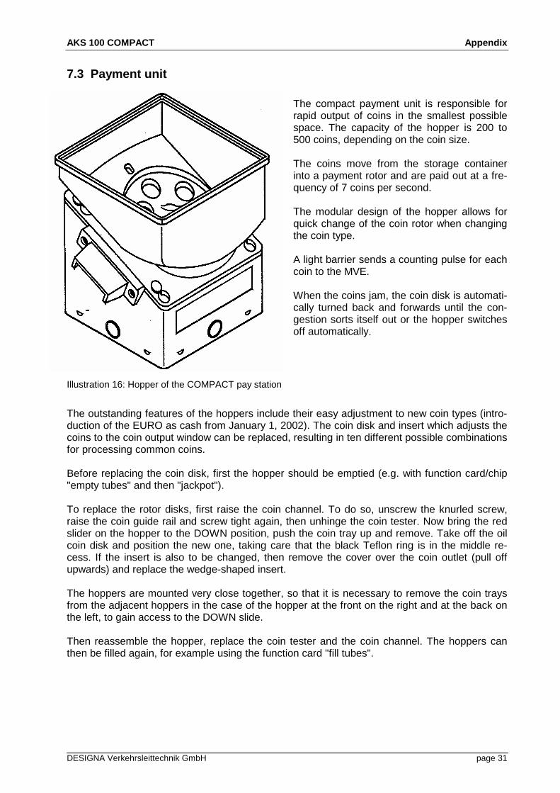
7.3 Payment unit
The compact payment unit is responsible forrapid output of coins in the smallest possiblespace. The capacity of the hopper is 200 to500 coins, depending on the coin size.
The coins move from the storage containerinto a payment rotor and are paid out at a fre-quency of 7 coins per second.
The modular design of the hopper allows forquick change of the coin rotor when changingthe coin type.
A light barrier sends a counting pulse for eachcoin to the MVE.
When the coins jam, the coin disk is automati-cally turned back and forwards until the con-gestion sorts itself out or the hopper switchesoff automatically.
Illustration 16: Hopper of the COMPACT pay station
The outstanding features of the hoppers include their easy adjustment to new coin types (intro-duction of the EURO as cash from January 1, 2002). The coin disk and insert which adjusts thecoins to the coin output window can be replaced, resulting in ten different possible combinationsfor processing common coins.
Before replacing the coin disk, first the hopper should be emptied (e.g. with function card/chip"empty tubes" and then "jackpot").
To replace the rotor disks, first raise the coin channel. To do so, unscrew the knurled screw,raise the coin guide rail and screw tight again, then unhinge the coin tester. Now bring the redslider on the hopper to the DOWN position, push the coin tray up and remove. Take off the oilcoin disk and position the new one, taking care that the black Teflon ring is in the middle re-cess. If the insert is also to be changed, then remove the cover over the coin outlet (pull offupwards) and replace the wedge-shaped insert.
The hoppers are mounted very close together, so that it is necessary to remove the coin traysfrom the adjacent hoppers in the case of the hopper at the front on the right and at the back onthe left, to gain access to the DOWN slide.
Then reassemble the hopper, replace the coin tester and the coin channel. The hoppers canthen be filled again, for example using the function card "fill tubes".