manual sentron expansion module pac...
TRANSCRIPT

Introduction 1
Safety instructions
2
Description
3
Installation
4
Parameter assignment/Addressing
5
Configuring
6
Maintenance, service and disposal
7
Interrupt, error, and system messages
8
Troubleshooting/FAQs
9
Technical data
10
Dimension sheets
11
Appendix
A
ESD directives
B
List of abbreviations
C
SENTRON
Expansion module PAC PROFIBUS DP
Manual
02/2009 A5E01168846B-05

Legal information Warning notice system
This manual contains notices you have to observe in order to ensure your personal safety, as well as to prevent damage to property. The notices referring to your personal safety are highlighted in the manual by a safety alert symbol, notices referring only to property damage have no safety alert symbol. These notices shown below are graded according to the degree of danger.
DANGER indicates that death or severe personal injury will result if proper precautions are not taken.
WARNING indicates that death or severe personal injury may result if proper precautions are not taken.
CAUTION with a safety alert symbol, indicates that minor personal injury can result if proper precautions are not taken.
CAUTION without a safety alert symbol, indicates that property damage can result if proper precautions are not taken.
NOTICE indicates that an unintended result or situation can occur if the corresponding information is not taken into account.
If more than one degree of danger is present, the warning notice representing the highest degree of danger will be used. A notice warning of injury to persons with a safety alert symbol may also include a warning relating to property damage.
Qualified Personnel The device/system may only be set up and used in conjunction with this documentation. Commissioning and operation of a device/system may only be performed by qualified personnel. Within the context of the safety notes in this documentation qualified persons are defined as persons who are authorized to commission, ground and label devices, systems and circuits in accordance with established safety practices and standards.
Proper use of Siemens products Note the following:
WARNING Siemens products may only be used for the applications described in the catalog and in the relevant technical documentation. If products and components from other manufacturers are used, these must be recommended or approved by Siemens. Proper transport, storage, installation, assembly, commissioning, operation and maintenance are required to ensure that the products operate safely and without any problems. The permissible ambient conditions must be adhered to. The information in the relevant documentation must be observed.
Trademarks All names identified by ® are registered trademarks of the Siemens AG. The remaining trademarks in this publication may be trademarks whose use by third parties for their own purposes could violate the rights of the owner.
Disclaimer of Liability We have reviewed the contents of this publication to ensure consistency with the hardware and software described. Since variance cannot be precluded entirely, we cannot guarantee full consistency. However, the information in this publication is reviewed regularly and any necessary corrections are included in subsequent editions.
Siemens AG Industry Sector Postfach 48 48 90026 NÜRNBERG GERMANY
A5E01168846B-05 Ⓟ 02/2009
Copyright © Siemens AG 2009. Technical data subject to change

PAC PROFIBUS DP Manual, 02/2009, A5E01168846B-05 3
Table of contents
1 Introduction................................................................................................................................................ 9
1.1 Purpose of this document ..............................................................................................................9 1.2 Orientation aids..............................................................................................................................9 1.3 Scope of delivery of the PAC PROFIBUS DP expansion module .................................................9 1.4 Latest information and correction sheet.......................................................................................10 1.5 Further documentation.................................................................................................................10
2 Safety instructions ................................................................................................................................... 11 2.1 Safety notes .................................................................................................................................11
3 Description............................................................................................................................................... 13 3.1 Area of application .......................................................................................................................13 3.2 Features .......................................................................................................................................14 3.3 Structure.......................................................................................................................................15 3.4 PROFIBUS functions ...................................................................................................................15 3.4.1 Functions with limited support......................................................................................................15 3.4.2 Unsupported functions .................................................................................................................16
4 Installation ............................................................................................................................................... 17 4.1 Procedure for installation and commissioning .............................................................................17 4.2 Unpacking ....................................................................................................................................18 4.3 Installation and connection ..........................................................................................................18 4.4 Measures to be performed prior to start-up .................................................................................21
5 Parameter assignment/Addressing.......................................................................................................... 23 5.1 Measured variables......................................................................................................................23 5.2 Cyclic data traffic..........................................................................................................................24 5.2.1 Introduction ..................................................................................................................................24 5.2.2 Basic type 1..................................................................................................................................25 5.2.3 Basic type 2..................................................................................................................................26 5.2.4 Basic type 3..................................................................................................................................26 5.2.5 Free choice of measured variables..............................................................................................28 5.2.6 Status information in the cyclic channel.......................................................................................28 5.2.7 Control bytes................................................................................................................................30 5.3 Acyclic data traffic ........................................................................................................................31 5.3.1 Introduction ..................................................................................................................................31 5.3.2 Content of the DPV1 data records...............................................................................................31 5.3.3 System diagnostics DS1..............................................................................................................33 5.3.4 Basic type 1 and basic type 2 DS51 ............................................................................................34 5.3.5 Status of the output signals DS68 ...............................................................................................35 5.3.6 Status of the DS69 input signals..................................................................................................35 5.3.7 Minimum and maximum current values DS72.............................................................................36

Table of contents
PAC PROFIBUS DP 4 Manual, 02/2009, A5E01168846B-05
5.3.8 Minimum and maximum voltage values DS73............................................................................ 36 5.3.9 Minimum and maximum power values DS74.............................................................................. 37 5.3.10 Minimum and maximum line frequency and THD values DS76 ................................................. 38 5.3.11 Status and diagnostics DS92...................................................................................................... 39 5.3.12 Commands DS93........................................................................................................................ 39 5.3.13 Current measured values, voltage measured values, and power measured values DS94........ 40 5.3.14 Working hours counter and universal counter DS95 .................................................................. 42 5.3.15 Settings for the SENTRON PAC DS131..................................................................................... 42 5.3.16 Limit value settings DS132.......................................................................................................... 44 5.3.17 Current DS202 ............................................................................................................................ 46 5.3.18 Voltage DS203 ............................................................................................................................ 47 5.3.19 Power DS204 .............................................................................................................................. 48 5.3.20 Energy counter DS205................................................................................................................ 48 5.3.21 Average power values over a demand period DS206 ................................................................ 49 5.3.22 I&M device identification DS255 ................................................................................................. 50 5.3.23 Addressing parameter................................................................................................................. 52 5.4 Reading and writing data record with SIMATIC S7 .................................................................... 53 5.5 Reading and writing data record with other PROFIBUS DP masters......................................... 53 5.6 Protocol sequence for read data record and write data record................................................... 53 5.7 Reading data records DS51 and DS205..................................................................................... 56 5.8 Data formats................................................................................................................................ 58 5.8.1 Energy counters .......................................................................................................................... 58 5.8.2 Limits ........................................................................................................................................... 58 5.8.3 Digital inputs status and digital outputs status............................................................................ 59
6 Configuring .............................................................................................................................................. 61 6.1 Default settings ........................................................................................................................... 61 6.2 Configuration scenarios .............................................................................................................. 61 6.3 Changing the address ................................................................................................................. 62 6.4 Configuring by means of the GSD file......................................................................................... 63 6.5 Information and settings on the SENTRON PAC Power Monitoring Device .............................. 70
7 Maintenance, service and disposal .......................................................................................................... 73 7.1 Cleaning ...................................................................................................................................... 73 7.2 Repair.......................................................................................................................................... 73 7.3 Disposal....................................................................................................................................... 74 7.4 Firmware updates ....................................................................................................................... 74
8 Interrupt, error, and system messages .................................................................................................... 75 8.1 Process interrupts ....................................................................................................................... 75 8.2 Diagnostics concept .................................................................................................................... 76 8.2.1 Diagnostic interrupt ..................................................................................................................... 76 8.2.2 Structure of the device status...................................................................................................... 78 8.2.3 Structure of the device-specific diagnostics................................................................................ 79 8.2.4 Device-specific diagnostic messages ......................................................................................... 81 8.3 Diagnostics LED.......................................................................................................................... 83

Table of contents
PAC PROFIBUS DP Manual, 02/2009, A5E01168846B-05 5
9 Troubleshooting/FAQs............................................................................................................................. 85 9.1 Power failure during firmware update ..........................................................................................85
10 Technical data ......................................................................................................................................... 87 10.1 Standards.....................................................................................................................................87 10.2 Technical data..............................................................................................................................87 10.3 Communication interface .............................................................................................................89 10.4 Labeling........................................................................................................................................91
11 Dimension sheets .................................................................................................................................... 93 11.1 Dimension sheets ........................................................................................................................93
A Appendix.................................................................................................................................................. 95 B ESD directives ......................................................................................................................................... 97
B.1 Electrostatic sensitive devices (ESD) ..........................................................................................97 C List of abbreviations................................................................................................................................. 99
C.1 Abbreviations ...............................................................................................................................99 Glossary ................................................................................................................................................ 101 Index...................................................................................................................................................... 103
Tables
Table 5- 1 Structure of basic type 1 ..............................................................................................................25 Table 5- 2 Basic type 2 transfers the following input data ............................................................................26 Table 5- 3 Length of basic type 3..................................................................................................................26 Table 5- 4 Basic type 3 transfers the following input data: ...........................................................................27 Table 5- 5 Structure of the 4 bytes of the status information - static diagnostics .........................................29 Table 5- 6 Structure of the control bytes .......................................................................................................30 Table 5- 7 Data records of the SENTRON PAC devices addressed via slot number 1 ...............................32 Table 5- 8 DPV1 data records for the PAC PROFIBUS DP expansion module...........................................32 Table 5- 9 Structure of data record DS1 - read access only.........................................................................33 Table 5- 10 Structure of data record DS51 - read access only.......................................................................34 Table 5- 11 Structure of data record DS68 - read access and write access ..................................................35 Table 5- 12 Structure of data record DS69 - read access only.......................................................................35 Table 5- 13 Structure of data record DS72 - read access only.......................................................................36 Table 5- 14 Structure of data record DS73 - read access only.......................................................................36 Table 5- 15 Structure of data record DS74 - read access only.......................................................................37 Table 5- 16 Structure of data record DS76 - read access only.......................................................................38 Table 5- 17 Structure of data record DS92 - read access only.......................................................................39 Table 5- 18 Structure of data record DS93 - write access only ......................................................................39
Table of contents
PAC PROFIBUS DP 6 Manual, 02/2009, A5E01168846B-05
Table 5- 19 Structure of data record DS94 - read access only...................................................................... 40 Table 5- 20 Structure of data record DS95 - read access and write access.................................................. 42 Table 5- 21 Structure of data record DS131 - read access and write access................................................ 42 Table 5- 22 Structure of data record DS132 - read access and write access................................................ 44 Table 5- 23 Structure of data record DS202 - read access only.................................................................... 46 Table 5- 24 Structure of data record DS203 - read access only.................................................................... 47 Table 5- 25 Structure of data record DS204 - read access only.................................................................... 48 Table 5- 26 Structure of data record DS205 - read access and write access................................................ 48 Table 5- 27 Structure of data record DS206 - read access only.................................................................... 49 Table 5- 28 Structure of data record DS255, IM0 data read access only ...................................................... 50 Table 5- 29 Structure of data record DS255, IM1 data - read access and write access ............................... 51 Table 5- 30 Structure of data record DS255, IM2 data - read access and write access ............................... 51 Table 5- 31 Structure of data record DS255, IM3 data - read access and write access ............................... 51 Table 5- 32 Structure of data record DS255, IM4 data - read access and write access ............................... 52 Table 5- 33 Meanings of the most important function numbers..................................................................... 55 Table 5- 34 Causes for sending Error Code 1 ............................................................................................... 55 Table 5- 35 Energy counters available in Float format................................................................................... 58 Table 5- 36 Available limit values................................................................................................................... 59 Table 5- 37 Scheme: Input statuses and output statuses of the SENTRON PAC Power Monitoring
Device ......................................................................................................................................... 60 Table 6- 1 Factory settings........................................................................................................................... 61 Table 6- 2 Composition of the file name ...................................................................................................... 63 Table 6- 3 GSD file extensions..................................................................................................................... 64 Table 6- 4 Name of the GSD file, e.g. .......................................................................................................... 64 Table 6- 5 Example of how to proceed......................................................................................................... 65 Table 6- 6 Communication status with meaning .......................................................................................... 71 Table 8- 1 Structure of the device diagnostics ............................................................................................. 75 Table 8- 2 Structure of the diagnostic interrupts of the SENTRON PAC Power Monitoring Device -
slave diagnostics......................................................................................................................... 76 Table 8- 3 Structure of the diagnostic interrupts of the SENTRON PAC Power Monitoring Device -
device diagnostics....................................................................................................................... 76 Table 8- 4 Structure of the diagnostic interrupts of the SENTRON PAC Power Monitoring Device -
interrupt messages...................................................................................................................... 77 Table 8- 5 Structure of the status specifier and the alarm specifier............................................................. 77 Table 8- 6 Structure of status 1 in byte 0 ..................................................................................................... 78 Table 8- 7 Structure of status 2 in byte 1 ..................................................................................................... 79 Table 8- 8 Structure of status 3 in byte 2 ..................................................................................................... 79 Table 8- 9 Device diagnostics data Yes/No: Structure of the device diagnostics in byte 10 ....................... 80

Table of contents
PAC PROFIBUS DP Manual, 02/2009, A5E01168846B-05 7
Table 8- 10 Communication faults: Structure of the device diagnostics in byte 11 and the interrupt message in byte 18......................................................................................................................80
Table 8- 11 Violation of the limits: Structure of the device diagnostics in byte 12 and the interrupt message in byte 19......................................................................................................................80
Table 8- 12 Invalid values and invalid settings: Structure of the device diagnostics in byte 13 and the interrupt message in byte 20........................................................................................................81
Table 8- 13 Implemented device diagnostic interrupts ...................................................................................81 Table 8- 14 Status and fault display by the LED.............................................................................................83 Table 10- 1 The device meets the following standards...................................................................................87 Table 10- 2 Mechanical data for the PAC PROFIBUS DP expansion module ...............................................87 Table 10- 3 Electrical data for the PAC PROFIBUS DP expansion module...................................................88 Table 10- 4 Ambient and environmental conditions........................................................................................88 Table 10- 5 Technical data for the communication interface ..........................................................................89 Table 10- 6 Pin assignment for the PROFIBUS connection ...........................................................................90 Table A- 1 Errors, comments, and suggestions for improvements ...............................................................96 Table C- 1 Meaning of abbreviations.............................................................................................................99
Figures
Figure 3-1 Schematic view of the side and front of the PAC PROFIBUS DP expansion module.................15 Figure 4-1 Mounting the PAC PROFIBUS DP expansion module................................................................20 Figure 5-1 Parameterizing the PAC PROFIBUS DP expansion module - example 1: Add basic type 1
to slot 1.........................................................................................................................................25 Figure 5-2 Configuring the PAC PROFIBUS DP expansion module - example 2: Inserting measured
variables.......................................................................................................................................28 Figure 5-3 Power Monitoring Device: Modular concept ................................................................................52 Figure 5-4 DPV1 message frame format read request .................................................................................54 Figure 5-5 DPV1 message frame format read response ..............................................................................54 Figure 5-6 DPV1 message frame format write request.................................................................................54 Figure 5-7 DPV1 message frame format write response ..............................................................................54 Figure 5-8 DPV1 message frame format interrupt response ........................................................................54 Figure 5-9 DPV1 error message frame .........................................................................................................54 Figure 5-10 Example: Reading DS51..............................................................................................................57 Figure 6-1 Configuring the integration of PROFIBUS using STEP 7 and the GSD file ................................62 Figure 6-2 Setting the PROFIBUS address on the SENTRON PACxxxx .....................................................70 Figure 10-1 9-pin sub D socket .......................................................................................................................90 Figure 10-2 The PAC PROFIBUS DP expansion module with label ..............................................................91 Figure 11-1 Side view and front view with sub D socket.................................................................................93

Table of contents
PAC PROFIBUS DP 8 Manual, 02/2009, A5E01168846B-05
Figure 11-2 Bottom view and top view with sub D socket connector and the dimensions of the pin contact between the PAC PROFIBUS DP expansion module and the SENTRON PAC ........... 93

PAC PROFIBUS DP Manual, 02/2009, A5E01168846B-05 9
Introduction 11.1 Purpose of this document
This manual is intended for: ● Planners ● Plant operators ● Commissioning engineers ● Service and maintenance personnel This manual contains: ● Details of the design of the PAC PROFIBUS DP expansion module ● Permissible conditions of use for the PAC PROFIBUS DP expansion module
Required basic knowledge General knowledge of the field of automation and basic knowledge of PROFIBUS are required to understand this manual.
1.2 Orientation aids
General information The manual includes the following orientation aids: ● Table of contents ● List of figures and tables ● List of abbreviations ● Glossary ● Index
1.3 Scope of delivery of the PAC PROFIBUS DP expansion module
Description The package includes: ● The PAC PROFIBUS DP expansion module ● The operating instructions for the PAC PROFIBUS DP expansion module

Introduction 1.4 Latest information and correction sheet
PAC PROFIBUS DP 10 Manual, 02/2009, A5E01168846B-05
1.4 Latest information and correction sheet
Up-to-the-minute information You can obtain further assistance by calling the following numbers: Technical Assistance: Phone: +49 (0) 911-895-5900 (8°° —17°° CET) Fax: +49 (0) 911-895-5907
On the Internet at: E-mail: Technical assistance (mailto:[email protected]) Internet: Technical assistance (http://www.siemens.de/lowvoltage/technical-assistance)
Correction sheet A correction sheet is included at the end of the manual. Please use it to record your suggestions for improvements, additions and corrections, and return the sheet to us. This will help us to improve the next edition of the manual.
1.5 Further documentation
Overview You can find more information, e.g. parameters, values, and setting options for the SENTRON PAC Power Monitoring Device in the following manuals: ● Manual for the SENTRON PAC Power Monitoring Device ● Operating instructions for the SENTRON PAC Power Monitoring Device You can find more information on SIMATIC in the following manuals: ● SIMATIC NET "PROFIBUS Network Manual" ● SIMATIC "Configuring Hardware and Connections with STEP 7" ● "SIMATIC PCS 7 Block Library PAC3200" ● "SENTRON PAC3200 block library for SIMATIC WinCC" Support (http://support.automation.siemens.com) You can find more information on PROFIBUS in the: PROFIBUS RS485-IS User and Installation Guide (http://www.profibus.com/pall/meta/downloads/article/00332/) You can find more information on the PAC PROFIBUS DP expansion module in the operating instructions for the PAC PROFIBUS DP expansion module.

PAC PROFIBUS DP Manual, 02/2009, A5E01168846B-05 11
Safety instructions 22.1 Safety notes
General safety notes
DANGER
Danger! High voltage Will cause death or serious injury. Turn off and lock out all power supplying this device before working on this device.
NOTICE Damage due to moisture Moisture or wetness can affect the operating capability of the PAC PROFIBUS DP expansion module. Make sure that no moisture or wetness can find its way into the PAC PROFIBUS DP expansion module. Do not operate the PAC PROFIBUS DP expansion module in an environment affected by high humidity or wetness. Note the environmental requirements of the SENTRON PAC Power Monitoring Device.

Safety instructions 2.1 Safety notes
PAC PROFIBUS DP 12 Manual, 02/2009, A5E01168846B-05

PAC PROFIBUS DP Manual, 02/2009, A5E01168846B-05 13
Description 33.1 Area of application
The PAC PROFIBUS DP expansion module is designed for use with a SENTRON PAC Power Monitoring Device. The guidelines for the SENTRON PAC Power Monitoring Device also apply to the PAC PROFIBUS DP expansion module.
Area of application of the PAC PROFIBUS DP expansion module The PAC PROFIBUS DP expansion module connects the SENTRON PAC Power Monitoring Device to the PROFIBUS network. This integrates the SENTRON PAC Power Monitoring Device into power management systems and automation systems, e.g.: ● TIA environment ● SIMATIC, with, for example:
– The block libraries display the measured values in faceplates and make these available in the SIMATIC S7 for further processing.
– SIMATIC S7 CPUs contain system function blocks (SFB52, SFB53, SFB54). With these, the CPUs can read and write the data records, and read the alarm messages.
Description 3.2 Features
PAC PROFIBUS DP 14 Manual, 02/2009, A5E01168846B-05
3.2 Features You can use the PAC PROFIBUS DP expansion module to access the SENTRON PAC Power Monitoring Devices during operation.
Overview Features include: ● Communication based on the PROFIBUS DP master-slave principle:
The PAC PROFIBUS DP expansion module provides the PROFIBUS DP master with measured values of the SENTRON PAC Power Monitoring Device. It receives information, e.g. commands, from the PROFIBUS DP master, and forwards this information to the SENTRON PAC Power Monitoring Device.
● Function: PROFIBUS DP slave ● Communication with the class 1 master and the class 2 masters ● Cyclic data transfer ● Acyclic data transfer ● Specific GSD file for every Power Monitoring Device type. This allows correct integration
into the controller. ● Automatic detection of the baud rate ● Clock synchronization depending on the device type ● Setting the PROFIBUS address:
– At the device – With parameterization software – Per PROFIBUS
● Generation of diagnostic interrupts and process interrupts ● Diagnostics also via the local display ● Status display via LED ● To ensure galvanic isolation between the SENTRON PAC Power Monitoring Device and
the PROFIBUS.

Description 3.3 Structure
PAC PROFIBUS DP Manual, 02/2009, A5E01168846B-05 15
3.3 Structure
Structure of the PAC PROFIBUS DP expansion module
(1) Sub D socket (2) Screw for mounting the PAC PROFIBUS DP expansion module on the
SENTRON PAC Power Monitoring Device (3) Ventilation slots (4) LED
Figure 3-1 Schematic view of the side and front of the PAC PROFIBUS DP expansion module
3.4 PROFIBUS functions
3.4.1 Functions with limited support
Functions with limited support You can operate the SENTRON PACxxxx Power Monitoring Device downstream of a Y link only in DPV0 mode. For this purpose, configure the SENTRON PACxxxx in the HW Config as a DPV0 slave. All acyclic services and interrupts are switched off, as is usual with DPV0. As a result, the SENTRON PACxxxx does not supply any interrupts. Instead of interrupts, the master evaluates the device diagnostics messages.

Description 3.4 PROFIBUS functions
PAC PROFIBUS DP 16 Manual, 02/2009, A5E01168846B-05
3.4.2 Unsupported functions
Unsupported functions The following PROFIBUS functions are not supported: ● SYNC / UNSYNC ● FREEZE / UNFREEZE
PAC PROFIBUS DP Manual, 02/2009, A5E01168846B-05 17
Installation 44.1 Procedure for installation and commissioning
The following system configuration information must be available: ● Installation location of the device ● Planned PROFIBUS address
Procedure 1. Mount the SENTRON PAC Power Monitoring Device and the PAC PROFIBUS DP
expansion module. 2. Connect the SENTRON PAC Power Monitoring Device. 3. Connect the PAC PROFIBUS DP expansion module to the PROFIBUS network. 4. Check all connections and settings. 5. Apply supply voltage to the SENTRON PAC Power Monitoring Device. The
SENTRON PAC Power Monitoring Device and expansion module are then ready for operation.
6. Parameterize the SENTRON PAC Power Monitoring Device as described in the manual for the SENTRON PACxxxx Power Monitoring Device.
7. Set the planned PROFIBUS address on the SENTRON PAC Power Monitoring Device. 8. Configure the PAC PROFIBUS DP expansion module. The STEP 7 HW Config, for
example, can be used as the configuring tool. – Assign the SENTRON PAC Power Monitoring Device to the PROFIBUS network. – Link the device-specific GSD file for the PAC PROFIBUS DP expansion module. – Select the basic types or the desired measured variables for the SENTRON PAC
Power Monitoring Device. – Transfer the parameter assignment to the PROFIBUS DP master.
See also Unpacking (Page 18) Installation and connection (Page 18) Measures to be performed prior to start-up (Page 21) Cyclic data traffic (Page 24) Default settings (Page 61) Configuration scenarios (Page 61) Changing the address (Page 62) Configuring by means of the GSD file (Page 63)

Installation 4.2 Unpacking
PAC PROFIBUS DP 18 Manual, 02/2009, A5E01168846B-05
4.2 Unpacking Observe the ESD guidelines. Open the packaging with care. Do not use excessive force.
Checks After receiving the module, and before installing it, you should make the following checks: ● Check the packaging for damage. ● Make sure that the package contents are complete. ● Check the module for external damage. Please contact your Siemens sales partner in the following cases: ● The packaging is damaged ● The contents of the package are not complete ● The module is damaged
Storage Store the PAC PROFIBUS DP expansion module in a dry place.
NOTICE Formation of condensation Store the device in the service room for at least two hours before applying voltage to the device for the first time. This will equalize the temperature and prevent the formation of condensation.
See also Electrostatic sensitive devices (ESD) (Page 97)
4.3 Installation and connection
Tools To install the PAC PROFIBUS DP expansion module you will need the following tool: ● A PZ1 cross-tip screwdriver, 2.9 mm, 0.5 Nm cal. ISO 6789
Assembly Install the PAC PROFIBUS DP expansion module before operating the SENTRON PAC. Observe the ESD guidelines.

Installation 4.3 Installation and connection
PAC PROFIBUS DP Manual, 02/2009, A5E01168846B-05 19
CAUTION Impairment and endangering of operation Damaged components can impair and endanger operation. Never use damaged components.
CAUTION Faulty sub D connector and faulty connector to the SENTRON PAC Power Monitoring Device Dirty or bent pins can affect the function of the connectors. The connectors can be destroyed. Do not allow the pins to become dirty. Make sure that: • There are no metal parts between the pins. • There are no metal parts adhering to the pins. • The pins do not bend. Do not touch the pins.
NOTICE Do not cover the ventilation slots If the ventilation slots are covered, the PAC PROFIBUS DP expansion module can overheat. Make sure that the ventilation slots are not covered.
Installation 4.3 Installation and connection
PAC PROFIBUS DP 20 Manual, 02/2009, A5E01168846B-05
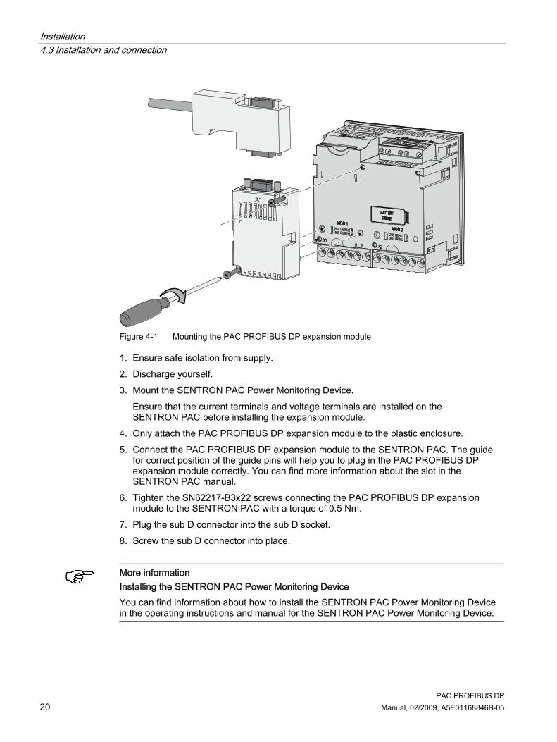
Figure 4-1 Mounting the PAC PROFIBUS DP expansion module
1. Ensure safe isolation from supply. 2. Discharge yourself. 3. Mount the SENTRON PAC Power Monitoring Device.
Ensure that the current terminals and voltage terminals are installed on the SENTRON PAC before installing the expansion module.
4. Only attach the PAC PROFIBUS DP expansion module to the plastic enclosure. 5. Connect the PAC PROFIBUS DP expansion module to the SENTRON PAC. The guide
for correct position of the guide pins will help you to plug in the PAC PROFIBUS DP expansion module correctly. You can find more information about the slot in the SENTRON PAC manual.
6. Tighten the SN62217-B3x22 screws connecting the PAC PROFIBUS DP expansion module to the SENTRON PAC with a torque of 0.5 Nm.
7. Plug the sub D connector into the sub D socket. 8. Screw the sub D connector into place.
More information Installing the SENTRON PAC Power Monitoring Device You can find information about how to install the SENTRON PAC Power Monitoring Device in the operating instructions and manual for the SENTRON PAC Power Monitoring Device.
Installation 4.4 Measures to be performed prior to start-up
PAC PROFIBUS DP Manual, 02/2009, A5E01168846B-05 21
The following general points must be observed when connecting: ● Equipotential bonding of the PAC PROFIBUS DP expansion module ● Bus terminating resistors
Note Bus terminating resistor There is no bus terminating resistor in the PAC PROFIBUS DP expansion module. The bus terminator is provided by the PROFIBUS adaptor plug, which includes a bus terminating resistor. You can find more information in the operating instructions for the PROFIBUS adaptor plug.
Please note: ● The PROFIBUS installation guidelines in "PROFIBUS RS485-IS User and Installation
Guideline" ● The "SIMATIC NET PROFIBUS Network Manual"
See also Further documentation (Page 10) Safety notes (Page 11) Electrostatic sensitive devices (ESD) (Page 97) Unpacking (Page 18) Measures to be performed prior to start-up (Page 21)
4.4 Measures to be performed prior to start-up
Checks Once you have correctly installed the PAC PROFIBUS DP expansion module, you should carry out the following checks: 1. Check that the PAC PROFIBUS DP expansion module is connected to the
SENTRON PAC Power Monitoring Device correctly. 2. Check that the connector of the PROFIBUS cable is plugged into the sub D socket of the
PAC PROFIBUS DP expansion module correctly and screwed down tightly. 3. Check that the ventilation slots are not covered.

Installation 4.4 Measures to be performed prior to start-up
PAC PROFIBUS DP 22 Manual, 02/2009, A5E01168846B-05

PAC PROFIBUS DP Manual, 02/2009, A5E01168846B-05 23
Parameter assignment/Addressing 55.1 Measured variables
The measured variables and status information of the SENTRON PAC are available to the higher-level power management system or automation system via PROFIBUS.
Information on the measured variables The measured variables include, for example: ● The measured values ● The maximum/minimum values of the measured values ● The energy values The status information includes, for example: ● The set limit values ● The device statuses You can find a detailed description of the measured variables in the manuals of the relevant SENTRON PACxxxx. In this manual, you will find the measured variables for PROFIBUS DP. The measured variables and status information are offered both in cyclic data traffic and acyclic data traffic. In cyclic data traffic, the measured variables and status information are offered as: ● Pre-defined structure, the basic types ● Individual measured variables In acyclic data traffic, the measured variables and status information are offered as data records.
Note Block libraries for SIMATIC The SENTRON PACxxxx offers extensive and diverse measured variables and status information. The SENTRON PACxxxx block libraries for SIMATIC simplify and facilitate integration into the TIA environment and and the SIMATIC environment.
See also Introduction (Page 9) Energy counters (Page 58) Further documentation (Page 10)
Parameter assignment/Addressing 5.2 Cyclic data traffic
PAC PROFIBUS DP 24 Manual, 02/2009, A5E01168846B-05
5.2 Cyclic data traffic
5.2.1 Introduction
Description In cyclic data traffic, each message frame transfers an optional number of user data. Cyclic data exchange is especially suitable for transferring information that is required continuously and quickly. The time interval between two message frames depends on: ● The number of nodes ● The data volume ● The baud rate All available data types that PROFIBUS can transfer are defined in the GSD file for the SENTRON PAC Power Monitoring Device. There are three basic types with predefined measured variables for time-saving commissioning and efficient data transfer. The user can also define individual measured variables to be transferred.
Choosing the basic type You can configure each SENTRON PAC Power Monitoring Device individually. During the configuration process, you use the PROFIBUS DP configuring tool to select the following from the GSD file: ● A suitable combination of basic type 1, basic type 2 and other measured variables ● A suitable combination of basic type 3, and other measured variables
Note Note the quantity structure The maximum quantity structure of the SENTRON PACxxxx for PROFIBUS is 244 bytes of input data and 2 bytes of output data.
See also Standards (Page 87) Further documentation (Page 10)
Parameter assignment/Addressing 5.2 Cyclic data traffic
PAC PROFIBUS DP Manual, 02/2009, A5E01168846B-05 25
5.2.2 Basic type 1
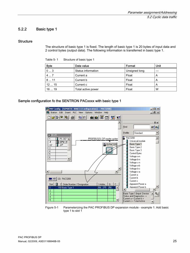
Structure The structure of basic type 1 is fixed. The length of basic type 1 is 20 bytes of input data and 2 control bytes (output data). The following information is transferred in basic type 1.
Table 5- 1 Structure of basic type 1
Byte Data value Format Unit 0 ... 3 Status information Unsigned long — 4 ... 7 Current a Float A 8 ... 11 Current b Float A 12 ... 15 Current c Float A 16 ... 19 Total active power Float W
Sample configuration fo the SENTRON PACxxxx with basic type 1
Figure 5-1 Parameterizing the PAC PROFIBUS DP expansion module - example 1: Add basic
type 1 to slot 1

Parameter assignment/Addressing 5.2 Cyclic data traffic
PAC PROFIBUS DP 26 Manual, 02/2009, A5E01168846B-05
See also Status information in the cyclic channel (Page 28) Control bytes (Page 30) Basic type 2 (Page 26) Basic type 1 and basic type 2 DS51 (Page 34)
5.2.3 Basic type 2
Structure Basic type 2 is an extension of basic type 1. This means that you can easily add basic type 1 and basic type 2 during the project design phase. You can also use basic type 2 as a separate unit. The structure of basic type 2 is fixed. Basic type 2 is 24 bytes.
Table 5- 2 Basic type 2 transfers the following input data
Byte Data value Format Unit 0 ... 3 Voltage a-b Float V 4 ... 7 Voltage b-c Float V 8 ... 11 Voltage c-a Float V 12 ... 19 Active energy import tariff 1 Double Float Wh 20 ... 23 Total power factor Float —
See also Basic type 1 (Page 25) Basic type 1 and basic type 2 DS51 (Page 34)
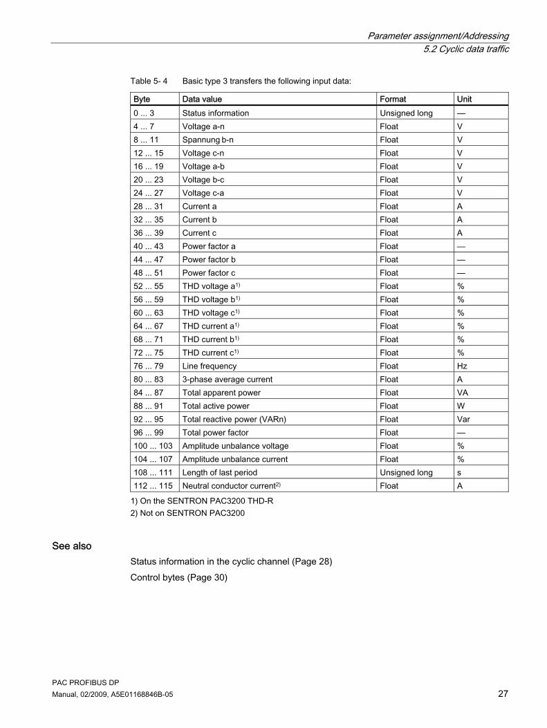
5.2.4 Basic type 3
Structure The structure of basic type 3 is fixed. Basic type 3 contains the control bytes.
Table 5- 3 Length of basic type 3
Device Length in byte SENTRON PAC3200 112 SENTRON PAC4200 116
Parameter assignment/Addressing 5.2 Cyclic data traffic
PAC PROFIBUS DP Manual, 02/2009, A5E01168846B-05 27
Table 5- 4 Basic type 3 transfers the following input data:
Byte Data value Format Unit 0 ... 3 Status information Unsigned long — 4 ... 7 Voltage a-n Float V 8 ... 11 Spannung b-n Float V 12 ... 15 Voltage c-n Float V 16 ... 19 Voltage a-b Float V 20 ... 23 Voltage b-c Float V 24 ... 27 Voltage c-a Float V 28 ... 31 Current a Float A 32 ... 35 Current b Float A 36 ... 39 Current c Float A 40 ... 43 Power factor a Float — 44 ... 47 Power factor b Float — 48 ... 51 Power factor c Float — 52 ... 55 THD voltage a1) Float % 56 ... 59 THD voltage b1) Float % 60 ... 63 THD voltage c1) Float % 64 ... 67 THD current a1) Float % 68 ... 71 THD current b1) Float % 72 ... 75 THD current c1) Float % 76 ... 79 Line frequency Float Hz 80 ... 83 3-phase average current Float A 84 ... 87 Total apparent power Float VA 88 ... 91 Total active power Float W 92 ... 95 Total reactive power (VARn) Float Var 96 ... 99 Total power factor Float — 100 ... 103 Amplitude unbalance voltage Float % 104 ... 107 Amplitude unbalance current Float % 108 ... 111 Length of last period Unsigned long s 112 ... 115 Neutral conductor current2) Float A
1) On the SENTRON PAC3200 THD-R 2) Not on SENTRON PAC3200
See also Status information in the cyclic channel (Page 28) Control bytes (Page 30)

Parameter assignment/Addressing 5.2 Cyclic data traffic
PAC PROFIBUS DP 28 Manual, 02/2009, A5E01168846B-05
5.2.5 Free choice of measured variables
Procedure In cyclic mode, you can specify other individual measured variables to be transferred.
Figure 5-2 Configuring the PAC PROFIBUS DP expansion module - example 2: Inserting measured
variables
5.2.6 Status information in the cyclic channel
Status information In cyclic data traffic, the status information is sent on every data exchange at the beginning of a basic type 1 and basic type 3 data structure. You can add the status information during the configuration phase. The status information is treated as diagnostics data for the device.
Parameter assignment/Addressing 5.2 Cyclic data traffic
PAC PROFIBUS DP Manual, 02/2009, A5E01168846B-05 29
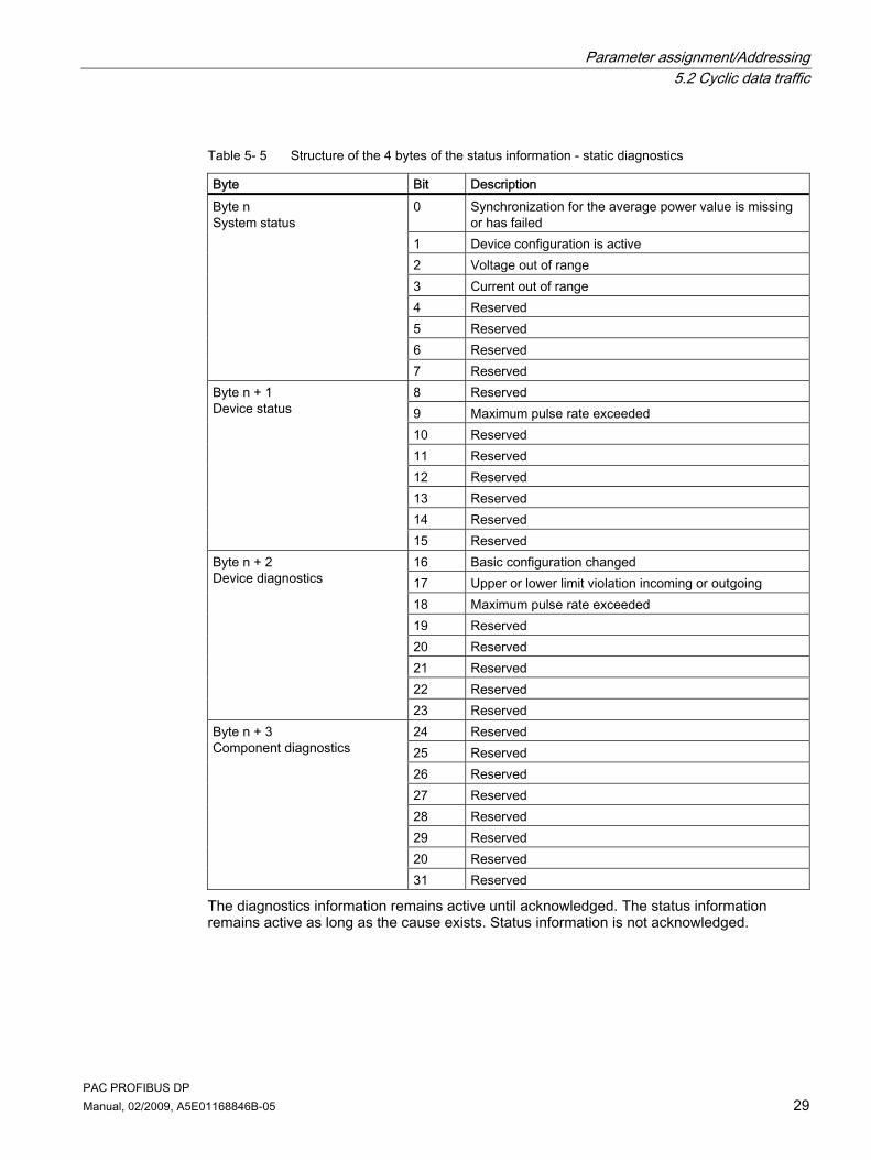
Table 5- 5 Structure of the 4 bytes of the status information - static diagnostics
Byte Bit Description 0 Synchronization for the average power value is missing
or has failed 1 Device configuration is active 2 Voltage out of range 3 Current out of range 4 Reserved 5 Reserved 6 Reserved
Byte n System status
7 Reserved 8 Reserved 9 Maximum pulse rate exceeded 10 Reserved 11 Reserved 12 Reserved 13 Reserved 14 Reserved
Byte n + 1 Device status
15 Reserved 16 Basic configuration changed 17 Upper or lower limit violation incoming or outgoing 18 Maximum pulse rate exceeded 19 Reserved 20 Reserved 21 Reserved 22 Reserved
Byte n + 2 Device diagnostics
23 Reserved 24 Reserved 25 Reserved 26 Reserved 27 Reserved 28 Reserved 29 Reserved 20 Reserved
Byte n + 3 Component diagnostics
31 Reserved
The diagnostics information remains active until acknowledged. The status information remains active as long as the cause exists. Status information is not acknowledged.

Parameter assignment/Addressing 5.2 Cyclic data traffic
PAC PROFIBUS DP 30 Manual, 02/2009, A5E01168846B-05
5.2.7 Control bytes
Description The control bytes are delivered with basic type 1 and basic type 3 as standard. Alternatively, you can add the control bytes during the configuration phase. These commands can be used to clear the memory contents or to change the tariff, for example. When you set a bit, the function belonging to the bit is activated. You must reset the control bit afterwards. The class 1 master sends these commands to the PROFIBUS DP slave.
Structure
Table 5- 6 Structure of the control bytes
Byte Bit Activation Description 0 Rising edge transition1) Reset the maximum values 1 Rising edge transition1) Reset the minimum values 2 Rising edge transition1) Reset energy counters 3 Rising edge transition1) Acknowledge device diagnostics 4 Rising edge transition1) Synchronization of the demand period 5 — Reserved 6 — Reserved
Byte n
7 — Reserved 8 Rising edge transition1) Switch to high tariff (HT) 9 Rising edge transition1) Switch to low tariff (LT) 10 Level sensitive Switch output 0.0: • ON = 1
• OFF = 0
11 Level sensitive Switch output 0.12): • ON = 1 • OFF = 0
12 — Reserved 13 — Reserved 14 — Reserved
Byte n + 1
15 — Reserved
1) Only a change from 0 to 1 activates this function, e.g., changing bit 8 from 0 to 1 brings about a changeover to the highest tariff. The value 1 or a reset from 1 to 0 has no effect.
2) SENTRON PAC4200 and higher
NOTICE Only one set of control bytes There can only be one set of control bytes per device. If you add basic type 1 or basic type 3 during the parameterization stage, then you must not add control bytes separately.

Parameter assignment/Addressing 5.3 Acyclic data traffic
PAC PROFIBUS DP Manual, 02/2009, A5E01168846B-05 31
See also Basic type 1 (Page 25)
5.3 Acyclic data traffic
5.3.1 Introduction
Requirements For acyclic data traffic, you require a DPV1-enabled class 1 master or a DPV1-enabled class 2 master.
Description In addition to cyclic data traffic, acyclic data can be transferred, e.g. parameters, diagnostics information, commands, further data. Acyclic data transfer takes place in parallel with cyclic data traffic. You can use acyclic data traffic with the following methods: ● The SENTRON PACxxxx block libraries for SIMATIC display the measured values in
faceplates and make these available in the SIMATIC S7 for further processing. ● SIMATIC S7 CPUs contain system function blocks (SFB52, SFB53, SFB54). With these,
the CPUs can read and write the data records individually, and read the alarm messages. ● Every other PROFIBUS DP master can implement the data records.
Note Acyclic connections to masters The expansion module supports up to five acyclic connections simultaneously: up to four with class 2 masters and one with a class 1 master.
5.3.2 Content of the DPV1 data records
Definition of the DPV1 data records The DPV1 data records are defined in a similar way to the SENTRON VL / WL circuit breakers. The system has a modular design.

Parameter assignment/Addressing 5.3 Acyclic data traffic
PAC PROFIBUS DP 32 Manual, 02/2009, A5E01168846B-05
Data records for the SENTRON PAC devices
Table 5- 7 Data records of the SENTRON PAC devices addressed via slot number 1
Data record number Description SENTRON PAC3200 only
SENTRON PACxxxx
Access
DS1 System diagnostics X X R DS51 Basic type 1 and basic type 2 X X R DS68 Status of the output signals X — RW DS69 Status of the input signals X — R DS72 Minimum and maximum current values X — R DS73 Minimum and maximum voltage values X — R DS74 Minimum and maximum power values X — R DS76 Minimum and maximum line frequency, THD values X — R DS92 Status and diagnostics X — R DS93 Commands X X W DS94 Current measured values, voltage measured values,
and power measured values X — R
DS95 Working hours counter and universal counter X — RW DS131 Settings for the SENTRON PAC X — RW DS132 Limit value settings X — RW DS202 Current X — R DS203 Voltage X — RW DS204 Power X — R DS205 Energy counters X X RW DS206 Average power values over a demand period X — R DS255 I&M device identification X X IM0: R
IM1 to IM4: RW
Data records for the PAC PROFIBUS DP expansion module In addition, there is a data record for the PAC PROFIBUS DP expansion module itself. You address this via slot number 0.
Table 5- 8 DPV1 data records for the PAC PROFIBUS DP expansion module
Data record number Description Access DS255 I&M data records RW
Abbreviation Meaning R Read W Write RW Read and write

Parameter assignment/Addressing 5.3 Acyclic data traffic
PAC PROFIBUS DP Manual, 02/2009, A5E01168846B-05 33
See also Addressing parameter (Page 52)
5.3.3 System diagnostics DS1
DS1 Data record DS1 contains the data for system diagnostics.
Table 5- 9 Structure of data record DS1 - read access only
Byte Bit position Length in bits Format Description 0 — 32 Unsigned char Header 4 — 32 Unsigned long Reserved 8 — 16 Unsigned short Reserved 10 — 8 Unsigned char Length of the diagnostics signal 11 — 8 Unsigned char Status type of the diagnostics 12 — 8 Unsigned char Slot number of the diagnostics 13 — 8 Unsigned char Specifier for the diagnostics
0 1 Bit Reserved 1 1 Bit Reserved 2 1 Bit Reserved 3 1 Bit Reserved 4 1 Bit Reserved 5 1 Bit Reserved 6 1 Bit Reserved
14
7 1 Bit The device diagnostics data is available.
0 1 Bit Internal communication not ready 1 1 Bit Internal communication is faulty 2 1 Bit Reserved 3 1 Bit Data invalid - internal fault
(CRC error) 4 1 Bit Reserved 5 1 Bit Data invalid - internal fault (frame
error) 6 1 Bit Data invalid - internal fault (timeout)
15
7 1 Bit Firmware PAC,Module incompatible

Parameter assignment/Addressing 5.3 Acyclic data traffic
PAC PROFIBUS DP 34 Manual, 02/2009, A5E01168846B-05
Byte Bit position Length in bits Format Description 0 1 Bit Voltage out of range 1 1 Bit Current out of range 2 1 Bit Maximum pulse rate exceeded 3 1 Bit Limit violations 4 1 Bit Reserved 5 1 Bit Reserved 6 1 Bit Reserved
16
7 1 Bit Reserved 0 1 Bit Output not remote operated 1 1 Bit Invalid val. for Op.Hrs/Univ.Cnt1) 2 1 Bit Invalid value for energy counter 3 1 Bit Invalid settings for PMD1) 4 1 Bit Invalid setting for limits1) 5 1 Bit Reserved (invalid data for DSxx) 6 1 Bit Reserved (invalid data for DSxx)
17
7 1 Bit Reserved (invalid data for DSxx) Total bytes: 18
1) On SENTRON PAC3200 only
5.3.4 Basic type 1 and basic type 2 DS51
DS51 Data record DS51 contains basic type 1 and basic type 2.
Table 5- 10 Structure of data record DS51 - read access only
Byte Number of bits
Format Description
0 32 Struct Header 4 32 Unsigned long Reserved 8 16 Unsigned short Reserved 10 160 Struct Basic type 1 30 192 Struct Basic type 2 Total bytes: 54
See also Basic type 1 (Page 25) Basic type 2 (Page 26) Reading data records DS51 and DS205 (Page 56)

Parameter assignment/Addressing 5.3 Acyclic data traffic
PAC PROFIBUS DP Manual, 02/2009, A5E01168846B-05 35
5.3.5 Status of the output signals DS68
DS68 Data record DS68 contains the output signals.
Table 5- 11 Structure of data record DS68 - read access and write access
Byte Number of bits
Format Description
0 32 Struct Header 4 32 Unsigned long Reserved 8 16 Unsigned short Reserved 10 32 Unsigned long Status of the digital outputs (bit-coded) 14 32 Unsigned long Reserved 18 32 Unsigned long Reserved 22 32 Unsigned long Reserved Total bytes: 26
See also Digital inputs status and digital outputs status (Page 59)
5.3.6 Status of the DS69 input signals
DS69 Data record DS69 contains the output signals.
Table 5- 12 Structure of data record DS69 - read access only
Byte Number of bits
Format Description
0 32 Struct Header 4 32 Unsigned long Reserved 8 16 Unsigned short Reserved 10 32 Unsigned long Status of the digital inputs (bit-coded) 14 32 Unsigned long Reserved 18 32 Unsigned long Reserved 22 32 Unsigned long Reserved Total bytes: 26
See also Digital inputs status and digital outputs status (Page 59)

Parameter assignment/Addressing 5.3 Acyclic data traffic
PAC PROFIBUS DP 36 Manual, 02/2009, A5E01168846B-05
5.3.7 Minimum and maximum current values DS72
DS72 Data record DS72 contains the maximum and minimum current values.
Table 5- 13 Structure of data record DS72 - read access only
Byte Number of bits
Format Description
0 32 Struct Header 4 32 Unsigned long Reserved 8 16 Unsigned short Reserved 10 32 Float Maximum current a 14 32 Float Maximum current b 18 32 Float Maximum current c 22 32 Float Max. 3-phase average current 26 32 Float Minimum current a 30 32 Float Minimum current b 34 32 Float Minimum current c 38 32 Float Min. 3-phase average current Total bytes: 42
5.3.8 Minimum and maximum voltage values DS73
DS73 Data record DS73 contains the maximum and minimum voltage values.
Table 5- 14 Structure of data record DS73 - read access only
Byte Number of bits Format Description 0 32 Struct Header 4 32 Unsigned long Reserved 8 16 Unsigned short Reserved 10 32 Float Maximum voltage a-n 14 32 Float Maximum voltage b-n 18 32 Float Maximum voltage c-n 22 32 Float Max. voltage a-b 26 32 Float Max. voltage a-c 30 32 Float Max. voltage c-a 34 32 Float Max. 3-phase average voltage ph-n 38 32 Float Max. 3-phase average voltage ph-ph 42 32 Float Minimum voltage a-n

Parameter assignment/Addressing 5.3 Acyclic data traffic
PAC PROFIBUS DP Manual, 02/2009, A5E01168846B-05 37
Byte Number of bits Format Description 46 32 Float Minimum voltage b-n 50 32 Float Minimum voltage c-n 54 32 Float Min. voltage a-b 58 32 Float Min. voltage b-c 62 32 Float Min. voltage c-a 66 32 Float Min. 3-phase average voltage ph-n 70 32 Float Min. 3-phase average voltage ph-ph Total bytes: 74
5.3.9 Minimum and maximum power values DS74
DS74 Data record DS74 contains the maximum and minimum power values.
Table 5- 15 Structure of data record DS74 - read access only
Byte Number of bits
Format Description
0 32 Struct Header 4 32 Unsigned long Reserved 8 16 Unsigned short Reserved 10 32 Float Maximum apparent power a 14 32 Float Maximum apparent power b 18 32 Float Maximum apparent power c 22 32 Float Maximum active power a 26 32 Float Maximum active power b 30 32 Float Maximum active power c 34 32 Float Maximum reactive power a 38 32 Float Maximum reactive power b 42 32 Float Maximum reactive power c 46 32 Float Maximum power factor a 50 32 Float Maximum power factor b 54 32 Float Maximum power factor c 58 32 Float Max. total apparent power 62 32 Float Max. total active power 66 32 Float Max. total reactive power 70 32 Float Max. total power factor 74 32 Float Minimum apparent power a 78 32 Float Minimum apparent power b 82 32 Float Minimum apparent power c 86 32 Float Minimum active power a

Parameter assignment/Addressing 5.3 Acyclic data traffic
PAC PROFIBUS DP 38 Manual, 02/2009, A5E01168846B-05
Byte Number of bits
Format Description
90 32 Float Minimum active power b 94 32 Float Minimum active power c 98 32 Float Minimum reactive power a 102 32 Float Minimum reactive power b 106 32 Float Minimum reactive power c 110 32 Float Minimum power factor a 114 32 Float Minimum power factor b 118 32 Float Minimum power factor c 122 32 Float Min. total apparent power 126 32 Float Min. total active power 130 32 Float Min. total reactive power 134 32 Float Min. total power factor Total bytes: 138
5.3.10 Minimum and maximum line frequency and THD values DS76
DS76 Data record DS76 contains the maximum and minimum line frequency values and the THD values.
Table 5- 16 Structure of data record DS76 - read access only
Byte Number of bits
Format Description
0 32 Struct Header 4 32 Unsigned long Reserved 8 16 Unsigend short Reserved 10 32 Float Maximum THD-R voltage a 14 32 Float Maximum THD-R voltage b 18 32 Float Maximum THD-R voltage c 22 32 Float Maximum THD-R current a 26 32 Float Maximum THD-R current b 30 32 Float Maximum THD-R current c 34 32 Float Max. line frequency 38 32 Float Min. line frequency Total bytes: 42

Parameter assignment/Addressing 5.3 Acyclic data traffic
PAC PROFIBUS DP Manual, 02/2009, A5E01168846B-05 39
5.3.11 Status and diagnostics DS92
DS92 Data record DS92 contains status information and diagnostic information.
Table 5- 17 Structure of data record DS92 - read access only
Byte Number of bits
Format Description
0 32 Struct Header 4 32 Unsigned long Reserved 8 16 Unsigned short Reserved 10 32 Unsigned long Device diagnostics and device status (bit-
coded) 14 32 Unsigned long Limit violations (bit-coded) 18 32 Unsigned long Relevant parameter changes counter 22 32 Unsigned long Counter all parameter changes 26 32 Unsigned long Counter limit violations Total bytes: 30
5.3.12 Commands DS93
DS93 Data record DS93 contains command information.
Table 5- 18 Structure of data record DS93 - write access only
Byte Bit position
Number of bits
Format Description
0 — 32 Struct Header 4 — 32 Unsigned long Reserved 8 — 16 Unsigned short Reserved 10 — 8 Unsigned char Command counter
0 11) Bit Reset the maximum values 1 11) Bit Reset the minimum values 2 11) Bit Resetting the energy counters 3 11) Bit Acknowledge device diagnostics 4 11) Bit Synchronization of the demand period 5 1 Bit Reserved 6 1 Bit Reserved
11
7 1 Bit Reserved

Parameter assignment/Addressing 5.3 Acyclic data traffic
PAC PROFIBUS DP 40 Manual, 02/2009, A5E01168846B-05
Byte Bit position
Number of bits
Format Description
0 11) Bit Switch to high tariff (HT) 1 11) Bit Switch to low tariff (LT) 2 12) Bit Switch output 0.0 3) (if parameterized) 3 12) Bit Switch output 0.1 3) 4) (if parameterized) 4 1 Bit Reserved 5 1 Bit Reserved 6 1 Bit Reserved
12
7 1 Bit Reserved 0 11) Bit Reset the device to the factory settings 1 11) Bit Reset the device
(no change to the IP address) 2 1 Bit Reset the PAC PROFIBUS DP expansion
module to the default 3 1 Bit Reserved 4 1 Bit Reserved 5 1 Bit Reserved 6 1 Bit Reserved
13
7 8 Bit Reserved 14 — 8 Unsigned char Reserved Total bytes: 15
1) "1" means: The action is executed. "0" means: The action is not executed.
2) "1" means: Signal = 1 "0" means: Signal = 0
3) If parameterized and available 4) Not on SENTRON PAC3200
5.3.13 Current measured values, voltage measured values, and power measured values DS94
DS94 Data record DS94 contains the current measured values, the voltage measured values, and the power measured values.
Table 5- 19 Structure of data record DS94 - read access only
Byte Number of bits
Format Description
0 32 Struct Header 4 32 Unsigned long Reserved 8 16 Unsigned short Reserved

Parameter assignment/Addressing 5.3 Acyclic data traffic
PAC PROFIBUS DP Manual, 02/2009, A5E01168846B-05 41
Byte Number of bits
Format Description
10 32 Float Voltage a-n 14 32 Float Voltage b-n 18 32 Float Voltage c-n 22 32 Float Voltage a-b 26 32 Float Voltage b-c 30 32 Float Voltage c-a 34 32 Float Current a 38 32 Float Current b 42 32 Float Current c 46 32 Float Apparent power a 50 32 Float Apparent power b 54 32 Float Apparent power c 58 32 Float Active power a 62 32 Float Active power b 66 32 Float Active power c 70 32 Float Reactive power a 74 32 Float Reactive power b 78 32 Float Reactive power c 82 32 Float Power factor a 86 32 Float Power factor b 90 32 Float Power factor c 94 32 Float THD-R voltage a 98 32 Float THD-R voltage b 102 32 Float THD-R voltage c 106 32 Float THD-R current a 110 32 Float THD-R current b 114 32 Float THD-R current c 118 32 Float Line frequency 122 32 Float 3-phase average voltage ph-n 126 32 Float 3-phase average voltage ph-ph 130 32 Float 3-phase average current 134 32 Float Total apparent power 138 32 Float Total active power 142 32 Float Total reactive power 146 32 Float Total power factor 150 32 Float Amplitude unbalance voltage 154 32 Float Amplitude unbalance current 158 32 Float Active tariff Total bytes: 162

Parameter assignment/Addressing 5.3 Acyclic data traffic
PAC PROFIBUS DP 42 Manual, 02/2009, A5E01168846B-05
5.3.14 Working hours counter and universal counter DS95
DS95 Data record DS95 contains the value of the working hours counter and the value of the configurable universal counter.
Table 5- 20 Structure of data record DS95 - read access and write access
Byte Number of bits
Format Description
0 32 Struct Header 4 32 Unsigned long Reserved 8 16 Unsigned short Reserved 10 32 Unsigned long Working hours counter1) 14 32 Unsigned long Universal counter1) Total bytes: 18
1) 0xFFFFFFFF means: No action. Every other value is accepted.
5.3.15 Settings for the SENTRON PAC DS131
DS131 Data record DS131 contains setting parameters for the SENTRON PAC Power Monitoring Device.
Table 5- 21 Structure of data record DS131 - read access and write access
Byte Number of bits
Format Description
0 32 Struct Header 4 32 Unsigned long Reserved 8 16 Unsigned short Reserved 10 32 Unsigned long Connection type:
• 0 = 3P4W • 1 = 3P3W • 2 = 3P4WB • 3 = 3P3WB • 4 = 1P2W
14 32 Unsigned long Voltage measurement using voltage transformers Yes/No
18 32 Unsigned long Primary voltage 22 32 Unsigned long Secondary voltage

Parameter assignment/Addressing 5.3 Acyclic data traffic
PAC PROFIBUS DP Manual, 02/2009, A5E01168846B-05 43
Byte Number of bits
Format Description
26 32 Unsigned long Current measurement using current transformers1)
= Yes 30 32 Unsigned long Primary current 34 32 Unsigned long Secondary current 38 32 Unsigned long Inverted current Yes/No 42 32 Unsigned long Line frequency 46 32 Float Zero point suppression (% rated current) 50 32 Unsigned long Demand period 54 32 Unsigned long Synchronization 58 32 Unsigned long Digital input 0.0 usage type 62 32 Unsigned long Reserved 66 32 Unsigned long Digital input 0.0
Use of counter information 70 32 Unsigned long Digital input 0.0
Weight of the counter information (pulses per kWh / kvarh)
74 32 Unsigned long Digital output 0.0 Vector group assignment
78 32 Unsigned long Digital output 0.0 usage type 82 32 Unsigned long Digital output 0.0 vector group assignment 86 32 Unsigned long Reserved 90 32 Unsigned long Digital output 0.0 source of counter signal 94 32 Unsigned long Digital output 0.0
Weight of the counter information (pulses per 1000 Wh / VARh)
98 32 Unsigned long Digital output 0.0 pulse length 102 32 Unsigned long Dialog language 106 32 Unsigned long Phase labels IEC/UL 110 32 Unsigned long Universal counter source 114 32 Unsigned long Display refresh cycle 118 32 Unsigned long Display contrast 122 32 Unsigned long Display backlight level 126 32 Unsigned long Display backlight dimmed 130 32 Unsigned long Display time until dimmed Total bytes: 134
1) This parameter is read-only.
See also Further documentation (Page 10)

Parameter assignment/Addressing 5.3 Acyclic data traffic
PAC PROFIBUS DP 44 Manual, 02/2009, A5E01168846B-05
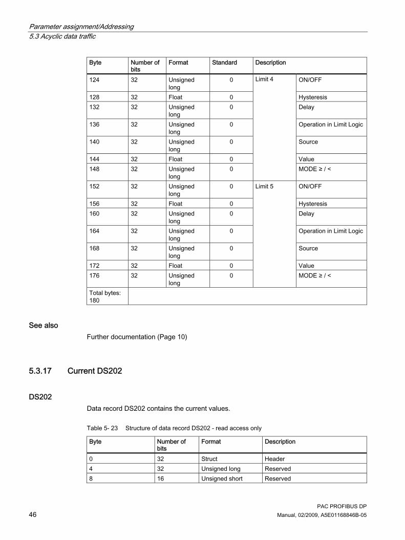
5.3.16 Limit value settings DS132
DS132 Data record DS132 contains parameters for setting the limit values.
Table 5- 22 Structure of data record DS132 - read access and write access
Byte Number of bits
Format Standard Description
0 8 Unsigned char
- Header coordination
1 8 Unsigned char
0x00 Header reserved
2 8 Unsigned char
- Header slot number
3 8 Unsigned char
0x00 Header sub-slot number
4 32 Unsigned long
0x00 Reserved
8 16 Unsigned short
0x00 Reserved
10 8 Unsigned char
0x01 Index of the limit value data record
11 8 Unsigned char
0x00 Reserved
12 32 Unsigned long
0 ON/OFF
16 32 Float 0 Hysteresis 20 32 Unsigned
long 0 Delay
24 32 Unsigned long
0 Operation in Limit Logic
28 32 Unsigned long
0 Source
32 32 Float 0 Value 36 32 Unsigned
long 0
Limit 0
MODE ≥ / <

Parameter assignment/Addressing 5.3 Acyclic data traffic
PAC PROFIBUS DP Manual, 02/2009, A5E01168846B-05 45
Byte Number of bits
Format Standard Description
40 32 Unsigned long
0 ON/OFF
44 32 Float 0 Hysteresis 48 32 Unsigned
long 0 Delay
52 32 Unsigned long
0 Operation in Limit Logic
56 32 Unsigned long
0 Source
60 32 Float 0 Value 64 32 Unsigned
long 0
Limit 1
MODE ≥ / <
68 32 Unsigned long
0 ON/OFF
72 32 Float 0 Hysteresis 76 32 Unsigned
long 0 Delay
80 32 Unsigned long
0 Operation in Limit Logic
84 32 Unsigned long
0 Source
88 32 Float 0 Value 92 32 Unsigned
long 0
Limit 2
MODE ≥ / <
96 32 Unsigned long
0 ON/OFF
100 32 Float 0 Hysteresis 104 32 Unsigned
long 0 Delay
108 32 Unsigned long
0 Operation in Limit Logic
112 32 Unsigned long
0 Source
116 32 Float 0 Value 120 32 Unsigned
long 0
Limit 3
MODE ≥ / <
Parameter assignment/Addressing 5.3 Acyclic data traffic
PAC PROFIBUS DP 46 Manual, 02/2009, A5E01168846B-05
Byte Number of bits
Format Standard Description
124 32 Unsigned long
0 ON/OFF
128 32 Float 0 Hysteresis 132 32 Unsigned
long 0 Delay
136 32 Unsigned long
0 Operation in Limit Logic
140 32 Unsigned long
0 Source
144 32 Float 0 Value 148 32 Unsigned
long 0
Limit 4
MODE ≥ / <
152 32 Unsigned long
0 ON/OFF
156 32 Float 0 Hysteresis 160 32 Unsigned
long 0 Delay
164 32 Unsigned long
0 Operation in Limit Logic
168 32 Unsigned long
0 Source
172 32 Float 0 Value 176 32 Unsigned
long 0
Limit 5
MODE ≥ / <
Total bytes: 180
See also Further documentation (Page 10)
5.3.17 Current DS202
DS202 Data record DS202 contains the current values.
Table 5- 23 Structure of data record DS202 - read access only
Byte Number of bits
Format Description
0 32 Struct Header 4 32 Unsigned long Reserved 8 16 Unsigned short Reserved

Parameter assignment/Addressing 5.3 Acyclic data traffic
PAC PROFIBUS DP Manual, 02/2009, A5E01168846B-05 47
Byte Number of bits
Format Description
10 32 Float Current a 14 32 Float Current b 18 32 Float Current c 22 32 Float THD-R current a 26 32 Float THD-R current b 30 32 Float THD-R current c 34 32 Float 3-phase average current Total bytes: 38
5.3.18 Voltage DS203
DS203 Data record DS203 contains the voltage values.
Table 5- 24 Structure of data record DS203 - read access only
Byte Number of bits Format Description 0 32 Struct Header 4 32 Unsigned long Reserved 8 16 Unsigned short Reserved 10 32 Float Voltage a-n 14 32 Float Voltage b-n 18 32 Float Voltage c-n 22 32 Float Voltage a-b 26 32 Float Voltage b-c 30 32 Float Voltage c-a 34 32 Float THD-R voltage a 38 32 Float THD-R voltage b 42 32 Float THD-R voltage c 46 32 Float 3-phase average voltage ph-n 50 32 Float 3-phase average voltage ph-ph Total bytes: 54

Parameter assignment/Addressing 5.3 Acyclic data traffic
PAC PROFIBUS DP 48 Manual, 02/2009, A5E01168846B-05
5.3.19 Power DS204
DS204 Data record DS204 contains the power values.
Table 5- 25 Structure of data record DS204 - read access only
Byte Number of bits Format Description 0 32 Struct Header 4 32 Unsigned long Reserved 8 16 Unsigned short Reserved 10 32 Float Apparent power a 14 32 Float Apparent power b 18 32 Float Apparent power c 22 32 Float Active power a 26 32 Float Active power b 30 32 Float Active power c 34 32 Float Reactive power a 38 32 Float Reactive power b 42 32 Float Reactive power c 46 32 Float Power factor a 50 32 Float Power factor b 54 32 Float Power factor c 58 32 Float Total apparent power 62 32 Float Total active power 66 32 Float Total reactive power 70 32 Float Total power factor Total bytes: 74
5.3.20 Energy counter DS205
DS205 Via data record DS205, the master can read out and set all energy counters in Double Float format.
Table 5- 26 Structure of data record DS205 - read access and write access
Byte Number of bits
Format Description
0 32 Struct Header 4 32 Unsigned long Reserved 8 16 Unsigned short Reserved

Parameter assignment/Addressing 5.3 Acyclic data traffic
PAC PROFIBUS DP Manual, 02/2009, A5E01168846B-05 49
Byte Number of bits
Format Description
10 64 Double Float Active energy import tariff 11) 18 64 Double Float Active energy import tariff 21) 26 64 Double Float Active energy export tariff 11) 34 64 Double Float Active energy export tariff 21) 42 64 Double Float Reactive energy import tariff 11) 50 64 Double Float Reactive energy import tariff 21) 58 64 Double Float Reactive energy export tariff 11) 66 64 Double Float Reactive energy export tariff 21) 74 64 Double Float Apparent energy tariff 11) 82 64 Double Float Apparent energy tariff 21) Total bytes: 90
1) 0xFFFFFFFFFFFFFFFF means: No action. Every other value is accepted.
See also Reading data records DS51 and DS205 (Page 56)
5.3.21 Average power values over a demand period DS206
DS206 Data record DS206 contains the average power values over a demand period.
Table 5- 27 Structure of data record DS206 - read access only
Byte Number of bits
Format Description
0 32 Struct Header 4 32 Unsigned long Reserved 8 16 Unsigned short Reserved 10 32 Float Cumulated active power import 14 32 Float Cumulated reactive power import 18 32 Float Cumulated active power export 22 32 Float Cumulated reactive power export 26 32 Float Max. active power in last period 30 32 Float Min. active power in last period 34 32 Float Max. reactive power in last period 38 32 Float Min. reactive power in last period 42 32 Unsigned long Length of last period in ms 46 32 Unsigned long Time stamp instantaneous period in s Total bytes: 50

Parameter assignment/Addressing 5.3 Acyclic data traffic
PAC PROFIBUS DP 50 Manual, 02/2009, A5E01168846B-05
5.3.22 I&M device identification DS255 Data record DS255 contains the I&M data for the unique identification of a SENTRON PAC Power Monitoring Device.
Addressing the I&M data records I&M data records for the SENTRON PACxxxx:
Address slot number 1 and index 255.
I&M data records for the PAC PROFIBUS DP expansion module:
Address slot number 0 and index 255.
You address slot number 0 with the diagnostics address you have defined in the properties of the DP slave in the HW Config, for example.
Table 5- 28 Structure of data record DS255, IM0 data read access only
Byte Number of bits Format Standard Description 0 8 Unsigned char 0x08 Extended function NUM 1 8 Unsigned char 0x00 Reserved 2 16 Unsigned short 65000 I&M index:= I&M 0 4 80 10 bytes 0x00 I&M header I&M data block 0 14 16 Unsigned short 42 IM0 manufacturer's ID1) 16 160 Char 20 — IM0 order number 36 128 Char 16 — IM0 serial number 52 16 Unsigned short — IM0 hardware version 54 32 1*char
3*unsigned short — IM0 firmware version
58 16 Unsigned short 0x0000 IM0 counter for changes 60 16 Unsigned short F600 IM0 profile ID 62 16 Unsigned short 0x00 IM0 Specific Profile ID 64 16 Unsigned short 0x0101 IM0 version of the I&M data 66 16 Unsigned short 001E IM0 supported I&M data Total bytes: 68
1) Standard: 42. "42" stands for Siemens AG.

Parameter assignment/Addressing 5.3 Acyclic data traffic
PAC PROFIBUS DP Manual, 02/2009, A5E01168846B-05 51
Table 5- 29 Structure of data record DS255, IM1 data - read access and write access
Byte Number of bits Format Standard Description 0 8 Unsigned char 0x08 Extended function NUM 1 8 Unsigned char 0x00 Reserved 2 16 Unsigned short 65001 I&M index:= I&M 1 4 80 10 bytes 0x00 I&M header I&M data block 1 14 256 Char 32 20h IM1 plant identifier 46 176 Char 22 20h IM1 location identifier Total bytes: 68
Table 5- 30 Structure of data record DS255, IM2 data - read access and write access
Byte Number of bits Format Standard Description 0 8 Unsigned char 0x08 Extended function NUM 1 8 Unsigned char 0x00 Reserved 2 16 Unsigned short 65002 I&M index:= I&M 2 4 80 10 bytes 0x00 I&M header I&M data block 2 14 128 Char 16 "YYY-MM-DD" IM2 installation date 30 304 Char 38 00h Reserved Total bytes: 68
Table 5- 31 Structure of data record DS255, IM3 data - read access and write access
Byte Number of bits Format Standard Description 0 8 Unsigned char 0x08 Extended function NUM 1 8 Unsigned char 0x00 Reserved 2 16 Unsigned short 65003 I&M index:= I&M 3 4 80 10 bytes 0x00 I&M header I&M data block 3 14 432 Char 54 20h IM3 comment Total bytes: 68
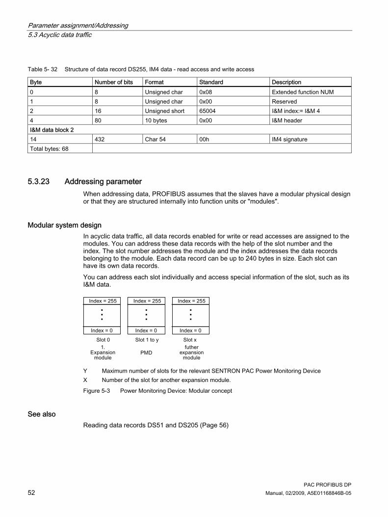
Parameter assignment/Addressing 5.3 Acyclic data traffic
PAC PROFIBUS DP 52 Manual, 02/2009, A5E01168846B-05
Table 5- 32 Structure of data record DS255, IM4 data - read access and write access
Byte Number of bits Format Standard Description 0 8 Unsigned char 0x08 Extended function NUM 1 8 Unsigned char 0x00 Reserved 2 16 Unsigned short 65004 I&M index:= I&M 4 4 80 10 bytes 0x00 I&M header I&M data block 2 14 432 Char 54 00h IM4 signature Total bytes: 68
5.3.23 Addressing parameter When addressing data, PROFIBUS assumes that the slaves have a modular physical design or that they are structured internally into function units or "modules".
Modular system design In acyclic data traffic, all data records enabled for write or read accesses are assigned to the modules. You can address these data records with the help of the slot number and the index. The slot number addresses the module and the index addresses the data records belonging to the module. Each data record can be up to 240 bytes in size. Each slot can have its own data records. You can address each slot individually and access special information of the slot, such as its I&M data.
Y Maximum number of slots for the relevant SENTRON PAC Power Monitoring Device X Number of the slot for another expansion module.
Figure 5-3 Power Monitoring Device: Modular concept
See also Reading data records DS51 and DS205 (Page 56)

Parameter assignment/Addressing 5.4 Reading and writing data record with SIMATIC S7
PAC PROFIBUS DP Manual, 02/2009, A5E01168846B-05 53
5.4 Reading and writing data record with SIMATIC S7 The SIMATIC S7 and other PROFIBUS DP masters offer functions for reading and writing data records.
SIMATIC S7 The SIMATIC S7 offers the following system function blocks: ● SFB 52 "RDREC" (read record): Read a data record ● SFB 53 "WRREC" (write record): Write data record ● SFB 54 "RALRM" (read alarm): Read alarm The description, functional principle, and use of the system function blocks is contained in the manuals for the SIMATIC and the STEP 7 Online Help.
5.5 Reading and writing data record with other PROFIBUS DP masters
PROFIBUS DP master Other PROFIBUS DP masters offer the following functions from the PROFIBUS Guideline "Communication and Proxy Function Blocks according to IEC 61131-3": ● Function block "RDREC" (read record): Read a data record ● Function block "WRREC" (write record): Write data record ● Function block "RALRM" (read alarm): Read alarms
5.6 Protocol sequence for read data record and write data record
Fundamentals The class 1 master has send authorization and corresponds cyclically over the MS0 channel consecutively with slave 1, slave 2 etc. by means of request and response. Following this, it passes the send authorization to the class 2 master. The class 2 master can establish an acyclic connection with any slave in the remaining time of the programmed cycle, and exchange data with this slave over the MS2 channel. At the end of the current cycle time, it returns the send authorization to the class 1 master. The class 1 master can exchange acyclic data with slaves in a similar way over the MS1 channel. Different data records have been defined for the SENTRON PAC Power Monitoring Device. Each data record has a maximum length of 200 bytes. This supports the routing property of the acyclic data. The DPV1 protocol is used for acyclic data exchange between a PROFIBUS DP class 1 master or a class 2 master and the slave. The DPV1 protocol is downward compatible. This allows you to connect PROFIBUS DP-V0 and PROFIBUS DP-V1 devices on one segment.
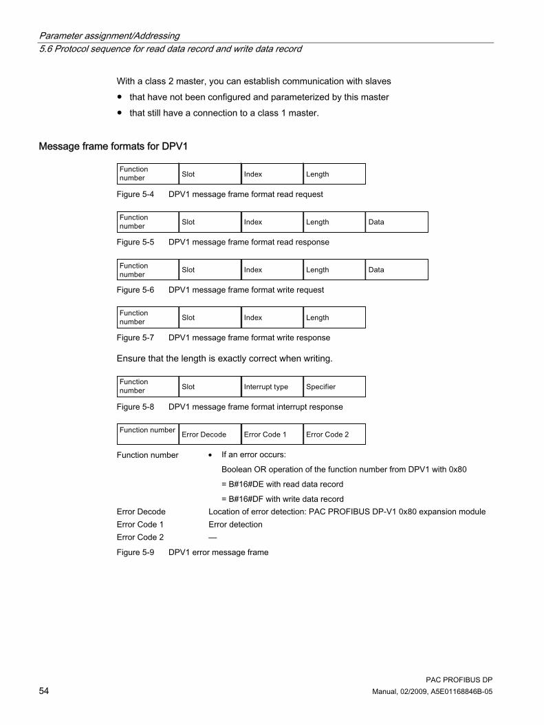
Parameter assignment/Addressing 5.6 Protocol sequence for read data record and write data record
PAC PROFIBUS DP 54 Manual, 02/2009, A5E01168846B-05
With a class 2 master, you can establish communication with slaves ● that have not been configured and parameterized by this master ● that still have a connection to a class 1 master.
Message frame formats for DPV1
Figure 5-4 DPV1 message frame format read request
Figure 5-5 DPV1 message frame format read response
Figure 5-6 DPV1 message frame format write request
Figure 5-7 DPV1 message frame format write response
Ensure that the length is exactly correct when writing.
Figure 5-8 DPV1 message frame format interrupt response
Function number • If an error occurs:
Boolean OR operation of the function number from DPV1 with 0x80
= B#16#DE with read data record
= B#16#DF with write data record Error Decode Location of error detection: PAC PROFIBUS DP-V1 0x80 expansion module Error Code 1 Error detection Error Code 2 —
Figure 5-9 DPV1 error message frame

Parameter assignment/Addressing 5.6 Protocol sequence for read data record and write data record
PAC PROFIBUS DP Manual, 02/2009, A5E01168846B-05 55
Note The structures of the error message frame and the error codes comply with the PROFIBUS standard. You can find further information in IEC 61158 and the "PROFIBUS Profile Guidelines Part 1: Identification & Maintenance Functions".
Function numbers
Table 5- 33 Meanings of the most important function numbers
Function number Meaning 0x48 Idle 0x51 Data Transport 0x56 Resource Manager Response 0x57 Initiate 0x58 Abort 0x5C Alarm Acknowledge (on MS1 only) 0x5E Read 0x5F Write
Causes
Table 5- 34 Causes for sending Error Code 1
Error Code 1 Error Meaning 0xA0 Reading error Occurs during read access to a DSx with "Write only"
access authorization 0xA1 Write error Occurs during write access to a DSx with "Read only"
access authorization 0xA9 The function is not supported Occurs during write access to IM0 data 0xB0 Invalid index Occurs when DSx not implemented, e.g.:
• If the index in the I&M header of the DS255 is invalid. • If the Extendet_Func_Num 0x08 in the I&M header of
the DS255 is missing.
0xB1 "Write" length error Occurs when length specification for Write DSx is incorrect 0xB2 Invalid slot Occurs when invalid slot specified for Read and Write DSx

Parameter assignment/Addressing 5.7 Reading data records DS51 and DS205
PAC PROFIBUS DP 56 Manual, 02/2009, A5E01168846B-05
Error Code 1 Error Meaning 0xB5 Status conflict Occurs in the following cases:
• Read DS255 without previous indexing • Read DSx without previous indexing • Read DSx, if this DSx has not previously been initialized
via Write DSx.1)
0xC2 Temporarily not possible. Occurs in the following cases: • Write DS.
The PAC PROFIBUS DP expansion module is busy with another job.
• Read DS. The PAC PROFIBUS DP expansion module is busy with the current job.
1) SENTRON PAC4200 and higher
See also Addressing parameter (Page 52) Reading data records DS51 and DS205 (Page 56)
5.7 Reading data records DS51 and DS205 In the case of SENTRON PACxxxx, data records DS51 and DS205 are read with the CALL mechanism in the same way as the I&M data of DS255. This does not apply for the SENTRON PAC3200.
Note Further information You can find further information on the CALL mechanism in IEC 61158-6, Chapter 6, and the "PROFIBUS Profile Guidelines Part 1: Identification & Maintenance Functions".
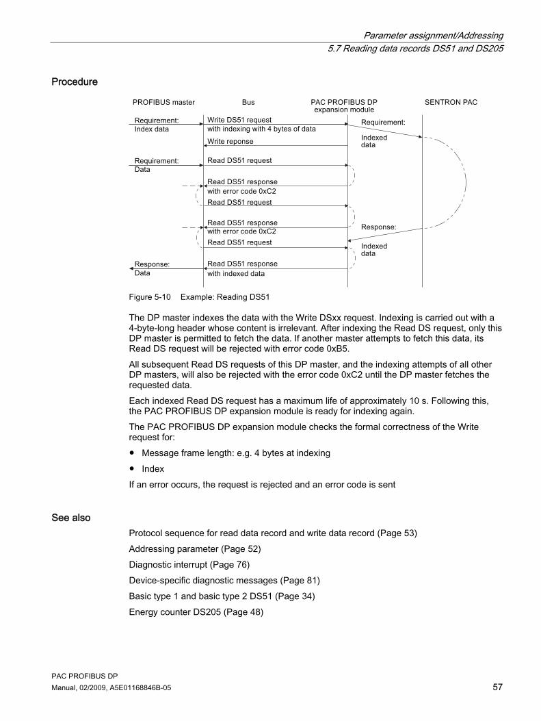
Parameter assignment/Addressing 5.7 Reading data records DS51 and DS205
PAC PROFIBUS DP Manual, 02/2009, A5E01168846B-05 57
Procedure
Figure 5-10 Example: Reading DS51
The DP master indexes the data with the Write DSxx request. Indexing is carried out with a 4-byte-long header whose content is irrelevant. After indexing the Read DS request, only this DP master is permitted to fetch the data. If another master attempts to fetch this data, its Read DS request will be rejected with error code 0xB5. All subsequent Read DS requests of this DP master, and the indexing attempts of all other DP masters, will also be rejected with the error code 0xC2 until the DP master fetches the requested data. Each indexed Read DS request has a maximum life of approximately 10 s. Following this, the PAC PROFIBUS DP expansion module is ready for indexing again. The PAC PROFIBUS DP expansion module checks the formal correctness of the Write request for: ● Message frame length: e.g. 4 bytes at indexing ● Index If an error occurs, the request is rejected and an error code is sent
See also Protocol sequence for read data record and write data record (Page 53) Addressing parameter (Page 52) Diagnostic interrupt (Page 76) Device-specific diagnostic messages (Page 81) Basic type 1 and basic type 2 DS51 (Page 34) Energy counter DS205 (Page 48)

Parameter assignment/Addressing 5.8 Data formats
PAC PROFIBUS DP 58 Manual, 02/2009, A5E01168846B-05
5.8 Data formats
5.8.1 Energy counters
Energy counters in Float format The SENTRON PACxxxx Power Monitoring Devices supply the measured variables listed in the table below in Float and Double Float format via PROFIBUS. The values can be more easily evaluated in Float in the SIMATIC, for example. High statuses of the energy counters are resolved in Float format with up to 7 decimal places.
Table 5- 35 Energy counters available in Float format
Name Format Value range Active energy import tariff 1 Float Overflow 1.0e+12 Active energy import tariff 2 Float Overflow 1.0e+12 Active energy export tariff 1 Float Overflow 1.0e+12 Active energy export tariff 2 Float Overflow 1.0e+12 Reactive energy import tariff 1 Float Overflow 1.0e+12 Reactive energy import tariff 2 Float Overflow 1.0e+12 Reactive energy export tariff 1 Float Overflow 1.0e+12 Reactive energy export tariff 2 Float Overflow 1.0e+12 Apparent energy tariff 1 Float Overflow 1.0e+12 Apparent energy tariff 2 Float Overflow 1.0e+12
In the GSD file, the measured variables in Double Float format are indicated by (D), and the measured variables in Float format by (F).
Note Resetting the energy counters If you carry out calculations with these measured variables in Float format, e.g. to calculate the daily or monthly consumption, inaccuracies arise in the case of values with more than 7 representable digits. You can ensure the accuracy of the measured values by resetting the energy counters before the counter value exceeds 7 digits.
See also Measured variables (Page 23)
5.8.2 Limits The SENTRON PAC3200 offers limit values. These limit values are available via the PROFIBUS in the "Limit Violations" measured variable.

Parameter assignment/Addressing 5.8 Data formats
PAC PROFIBUS DP Manual, 02/2009, A5E01168846B-05 59
Limit values of the SENTRON PAC3200 Power Monitoring Device
Table 5- 36 Available limit values
Name Byte Bit Format Value range Access Limit value logic 0 0 Bit 0, 1 R Limit value 0 0 Bit 0, 1 R Limit value 1 1 Bit 0, 1 R Limit value 2 2 Bit 0, 1 R Limit value 3 3 Bit 0, 1 R Limit value 4 4 Bit 0, 1 R Limit value 5
3
5 Bit 0, 1 R
R Read; read access
Note Limit violations can trigger diagnostic interrupts.
Limit values of other SENTRON PACxxxx Power Monitoring Devices You can find the limit values for the SENTRON PACxxxx Power Monitoring Devices in the relevant manual.
See also Structure of the device-specific diagnostics (Page 79) Device-specific diagnostic messages (Page 81)
5.8.3 Digital inputs status and digital outputs status
Input statuses and output statuses of the SENTRON PAC Power Monitoring Device The following are available via the PROFIBUS: ● The input status of the internal input of the SENTRON PACxxxx Power Monitoring Device
in the measured variable "Digital inputs status" ● The output status of the internal output of the SENTRON PACxxxx Power Monitoring
Device in the measured variable "Digital outputs status"

Parameter assignment/Addressing 5.8 Data formats
PAC PROFIBUS DP 60 Manual, 02/2009, A5E01168846B-05
Table 5- 37 Scheme: Input statuses and output statuses of the SENTRON PAC Power Monitoring Device
Bit 7 Bit 6 Bit 5 Bit 4 Bit 3 Bit 2 Bit 1 Bit 0 Byte 0 MSB — — — — — — — Byte 1 — — — — — — — — Byte 2 — — — — — — — — Byte 3 — — — — — — DI / DO 0.11) 2) DI /DO 0.01) 2) , LSB
1) = Read access 2) "0" = OFF; "1" = ON1)
Abbreviation Meaning LSB Least significant byte MSB Most significant byte
See also Status of the output signals DS68 (Page 35) Status of the DS69 input signals (Page 35)

PAC PROFIBUS DP Manual, 02/2009, A5E01168846B-05 61
Configuring 66.1 Default settings
Factory default settings
Table 6- 1 Factory settings
Parameter Value Address 126 Baud rate in bit/s Automatic recognition Type of SENTRON PAC Power Monitoring Device connected
Automatic recognition
Language The communication parameters are displayed in the language set on the SENTRON PAC Power Monitoring Device. Default setting: English
6.2 Configuration scenarios In the SIMATIC environment you can configure the SENTRON PAC Power Monitoring Device and the PAC PROFIBUS DP expansion module in the following way. ● Integration of the SENTRON PAC Power Monitoring Device via PROFIBUS using
STEP 7 and the device-specific GSD file

Configuring 6.3 Changing the address
PAC PROFIBUS DP 62 Manual, 02/2009, A5E01168846B-05
Configuring the integration of PROFIBUS using STEP 7 and the GSD file
Figure 6-1 Configuring the integration of PROFIBUS using STEP 7 and the GSD file
Note Configuration with other tools You can also use configuration tools from other manufacturers for the configuration.
6.3 Changing the address
Setting a unique address Every device requires a unique address. The address is stored in the PAC PROFIBUS DP expansion module. Address 126 is used for commissioning purposes only. It must not be used for data communication.

Configuring 6.4 Configuring by means of the GSD file
PAC PROFIBUS DP Manual, 02/2009, A5E01168846B-05 63
Change the address of each device before you begin transferring data. You can change the address: ● Via the menu of the SENTRON PAC Power Monitoring Device ● With SENTRON powerconfig via the Ethernet interface ● With the PROFIBUS configuring software, e.g., STEP 7 ● Via the PROFIBUS interface by means of a class 2 master
CAUTION
Address change on device immediately valid When you change the address of the PROFIBUS DP slave on the SENTRON PAC, the PAC PROFIBUS DP expansion module is automatically restarted as soon as you quit the menu. The new address is then active. Reconfigure the PROFIBUS DP master with the new address. Communication is interrupted until this change takes effect.
6.4 Configuring by means of the GSD file
Task of the GSD file The GSD file is a text file in ASCII format. It describes the following for the individual SENTRON PAC devices: ● The measured variables ● The status information ● The control information ● The communication characteristics The GSD file makes this data available to the class 1 master. The GSD file is the basis for the configuration of a device. PROFIBUS devices have a unique PROFIBUS ID number and a GSD file. The GSD file is matched to the SENTRON PAC Power Monitoring Device.
Naming convention of the GSD file The name of the GSD file contains the following information:
Table 6- 2 Composition of the file name
Places Meaning 1 ... 2 "SI" for Siemens 3 ... 4 Version of the GSD file, e.g. "01" for the first version 5 ... 8 Identification number; this is assigned by PI.

Configuring 6.4 Configuring by means of the GSD file
PAC PROFIBUS DP 64 Manual, 02/2009, A5E01168846B-05
Language of the GSD file The GSD file is language-dependent.
Table 6- 3 GSD file extensions
Language-dependent GSD file extension Language GSE English (ANSI) GSG German GSF French GSI Italian GSP Portuguese GSS Spanish GSD Language-neutral (English IEC)
Assignment of the GSD file to the device and firmware version of the expansion module
Table 6- 4 Name of the GSD file, e.g.
Name of the GSD file Meaning SIEM8163.GSx GSD file for the SENTRON PAC3200 Power
Monitoring Device with a PAC PROFIBUS DP-V0 expansion module with the firmware version 1.0.1
SI018163.GSx Version "01" of the GSD file for the SENTRON PAC3200 Power Monitoring Device with a PAC PROFIBUS DP-V1 expansion module with the firmware version 2.0.0
SI018173.GSx Version "01" of the GSD file for the SENTRON PAC4200 Power Monitoring Device with a PAC PROFIBUS DP expansion module with the firmware version 3.0.0
Note Latest version of the GSD file You can find the latest version of the GSD file in each case on the Internet Online service and support (http://www.siemens.com/automation/service&support).
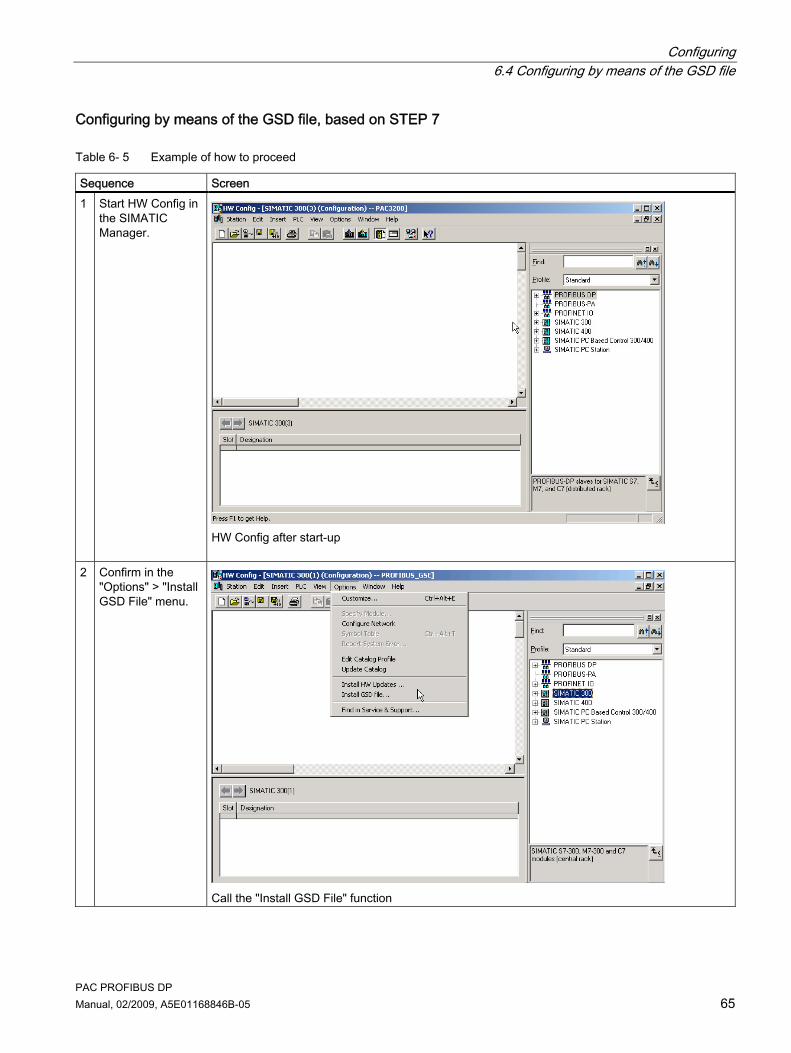
Configuring 6.4 Configuring by means of the GSD file
PAC PROFIBUS DP Manual, 02/2009, A5E01168846B-05 65
Configuring by means of the GSD file, based on STEP 7
Table 6- 5 Example of how to proceed
Sequence Screen 1 Start HW Config in
the SIMATIC Manager.
HW Config after start-up
2 Confirm in the "Options" > "Install GSD File" menu.
Call the "Install GSD File" function
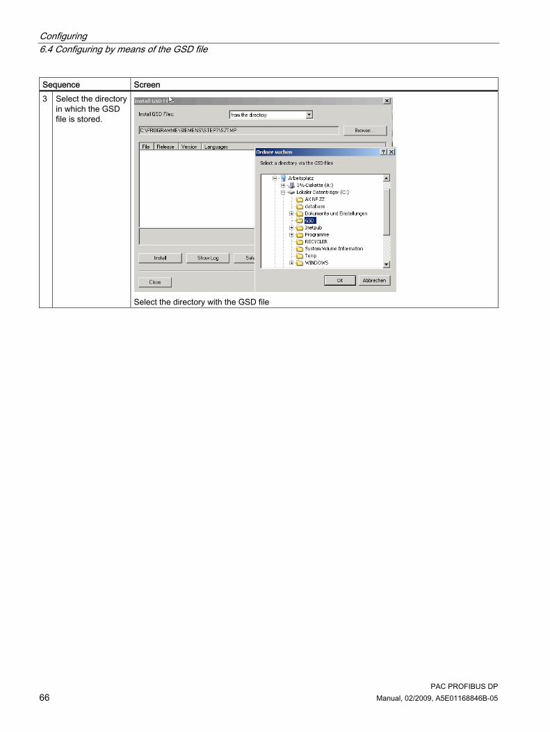
Configuring 6.4 Configuring by means of the GSD file
PAC PROFIBUS DP 66 Manual, 02/2009, A5E01168846B-05
Sequence Screen 3 Select the directory
in which the GSD file is stored.
Select the directory with the GSD file

Configuring 6.4 Configuring by means of the GSD file
PAC PROFIBUS DP Manual, 02/2009, A5E01168846B-05 67
Sequence Screen 4 Install the GSD file.
Installing GSD file
On successful completion of the installation of the GSD file, the following message is displayed:
Installation of the GSD file successfully completed

Configuring 6.4 Configuring by means of the GSD file
PAC PROFIBUS DP 68 Manual, 02/2009, A5E01168846B-05
Sequence Screen 5 Add a rack and
insert in it the modules that are required, e.g., the CPU with PROFIBUS DP interface. After inserting the CPU, a window is opened. Enter the address of the PROFIBUS master here.
Setting the PROFIBUS address of the master
6 Select the SENTRON PAC Power Monitoring Device in the hardware tree: "PROFIBUS DP" > "Additional Devices" > "SENTRON" > "PACxxxx"
Add the Power Monitoring Device to HW Config

Configuring 6.4 Configuring by means of the GSD file
PAC PROFIBUS DP Manual, 02/2009, A5E01168846B-05 69
Sequence Screen 7 Drag the
SENTRON PACXXXX Power Monitoring Device from the hardware tree to the PROFIBUS DP master system 1. Set the address of the PAC PROFIBUS DP expansion module.
Set the address of the PAC PROFIBUS DP expansion module
8 Click on the icon for the SENTRON PAC Power Monitoring Device.
HW Config with the integrated PAC PROFIBUS DP expansion module

Configuring 6.5 Information and settings on the SENTRON PAC Power Monitoring Device
PAC PROFIBUS DP 70 Manual, 02/2009, A5E01168846B-05
NOTICE Do not use the universal module Because of the predefined data types and the available measured values, the use of the STEP 7 universal module in the configuration is not supported.
See also Default settings (Page 61) Latest information and correction sheet (Page 10)
6.5 Information and settings on the SENTRON PAC Power Monitoring Device
When the PAC PROFIBUS DP expansion module is mounted on the SENTRON PAC Power Monitoring Device, you can read information about the PAC PROFIBUS DP expansion module, and set its address, on a separate screen form on the Power Monitoring Device.
Information and settings on the SENTRON PACxxxx Power Monitoring Device Depending on the version of the device, you call the following in the main menu of the Power Monitoring Device: ● SENTRON PAC "Settings" > "PROFIBUS Module" ● SENTRON PAC "Settings" > "Expansion Module" > "MODx" > "PROFIBUS Module" You then see the following screen:
Figure 6-2 Setting the PROFIBUS address on the SENTRON PACxxxx
You will find the following information listed in the upper half of the screen form: ● The order number ● The serial number of the PAC PROFIBUS DP expansion module ● The firmware version of the PAC PROFIBUS DP expansion module ● In the "DIAG" field, you can see the communication status of the PAC PROFIBUS DP
expansion module:

Configuring 6.5 Information and settings on the SENTRON PAC Power Monitoring Device
PAC PROFIBUS DP Manual, 02/2009, A5E01168846B-05 71
Table 6- 6 Communication status with meaning
Status Meaning BAUD_SRCH Searches the PROFIBUS master for the baud rate. WAIT_PRM The PAC PROFIBUS DP expansion module is waiting for parameterization or
a request from the master. PRM_FAULT Incorrect parameterization; e.g. wrong GSD file WAIT_CFG Parameterization is OK. The PAC PROFIBUS DP expansion module is waiting
for configuration. CFG_FAULT Incorrect configuration message frame, e.g. an incorrect measured variable
has been configured. DATA_EXCH Configuration is OK. Data is exchanged with a class 1 master. CON_MC2 Configuration is OK. The connection with a class 2 master has been
established.
"PROFIBUS ADDRESS": Each expansion module requires a unique address. The address 126 is the default for startup purposes. Change this address! Valid address area: 1 ... 126

Configuring 6.5 Information and settings on the SENTRON PAC Power Monitoring Device
PAC PROFIBUS DP 72 Manual, 02/2009, A5E01168846B-05
PAC PROFIBUS DP Manual, 02/2009, A5E01168846B-05 73
Maintenance, service and disposal 77.1 Cleaning
Description The PAC PROFIBUS DP expansion module is maintenance-free.
NOTICE Damage due to detergents Detergents can damage the device. Do not use detergents.
NOTICE Faulty connector Be careful not to bend the pins of the connector. Bent pins can destroy the connector.
1. Use only a dry, lint-free, antistatic cloth to clean the housing. 2. Clean the pins carefully using a brush.
7.2 Repair
Procedure
NOTICE Loss of certification and warranty If you open the module, the module certification will be lost and the Siemens warranty will be invalidated. Only the manufacturer is permitted to carry out repairs on the module. Return faulty or damaged modules to Siemens for repair or replacement.
If the module is faulty or damaged, proceed as follows: 1. Discharge yourself. 2. Remove the module. 3. Pack the module in a suitable manner to prevent it from being damaged during transport. 4. Return the module to Siemens. You can obtain the address from:
– Your Siemens sales partner – Technical Assistance
Maintenance, service and disposal 7.3 Disposal
PAC PROFIBUS DP 74 Manual, 02/2009, A5E01168846B-05
See also Latest information and correction sheet (Page 10) Electrostatic sensitive devices (ESD) (Page 97)
7.3 Disposal
Disposal and recycling Dispose of or recycle the module in accordance with the applicable laws and regulations in your country.
7.4 Firmware updates
SENTRON powerconfig
Note Performing a firmware update Before updating the firmware, consult Technical Assistance to confirm that it is necessary. Update the firmware only if absolutely necessary.
You update the firmware with the configuration software SENTRON powerconfig . Additional information on updating the firmware can be found in the online help for SENTRON powerconfig.
See also Power failure during firmware update (Page 85)

PAC PROFIBUS DP Manual, 02/2009, A5E01168846B-05 75
Interrupt, error, and system messages 88.1 Process interrupts
Information about the process interrupts The process interrupts report to the master SENTRON PACxxxx events that are defined as alarms and that occur during operation of the SENTRON PAC Power Monitoring Device. If several of these events occur simultaneously, only the last event is reported to the master as a process interrupt. In the SIMATIC environment, SFB 54 reads the process interrupt messages.
SENTRON PAC events You can find more information about the events in the manual of the SENTRON PACxxxx Power Monitoring Device.
Structure of the process interrupts
Table 8- 1 Structure of the device diagnostics
Byte 0 Byte 1 Byte 2 Byte 3 Byte 4 to byte x Sign-Len Length of the tag in bytes
Interrupt type1) Slot2) Specifier3) Event messages4)
1) "0x02" for the process interrupts 2) Slot number 0 for the PAC PROFIBUS DP expansion module;
Slot number 1 for the SENTRON PACxxxx Slot number x for a further expansion module
3) You can find further information in the Chapter "Diagnostic interrupt" in the table "Structure of the status specifier and the alarm specifier"
4) Please consult Support for more information on the event messages.

Interrupt, error, and system messages 8.2 Diagnostics concept
PAC PROFIBUS DP 76 Manual, 02/2009, A5E01168846B-05
8.2 Diagnostics concept
8.2.1 Diagnostic interrupt
Diagnostic information The following PROFIBUS DP diagnostic information is available: 1. Slave diagnostics in accordance with standard 2. Enhanced diagnostics
– Device diagnostics with diagnostic interrupts The PAC PROFIBUS DP expansion module reports device diagnostics to the master in the form of interrupts. The master must acknowledge the interrupts. Device faults or parameter errors are interrupt sources for diagnostic interrupts.
In the SIMATIC environment, SFB 54 reads the diagnostic interrupt messages.
Structure of the diagnostic interrupts
Table 8- 2 Structure of the diagnostic interrupts of the SENTRON PAC Power Monitoring Device - slave diagnostics
To standard Byte 0 Byte 1 Byte 2 Byte 3 Byte 4 Byte 5
High byte Low byte 81 63
Device status 1 to 3 PROFIBUS address of the master1)
Manufacturer's ID2) 1) This is the address of the master that has parameterized the slave and that has read and write access to the slave. If the value here is FFH, the slave has not been parameterized. 2) The manufacturer's ID identifies the slave model, e.g., "8163H" for the SENTRON PAC3200.
Table 8- 3 Structure of the diagnostic interrupts of the SENTRON PAC Power Monitoring Device - device diagnostics
To standard Manufacturer-specific Byte 6 Byte 7 Byte 8 Byte 9 Byte 10 Byte 11 Byte 12 Byte 13 Sign-Len Length of device diagnostics in bytes
Status type1)
Slot2) Specifier3) Device diagnostics data Yes/No
Communication faults
Violation of the limits
Invalid values and invalid settings
1) "0x81" for the status messages 2) Slot number 0 for the PAC PROFIBUS DP expansion module; Slot number 1 for the SENTRON PACxxxx Slot number x for a further expansion module 3) You can find further information in the table "Structure of the status specifier and the alarm specifier"
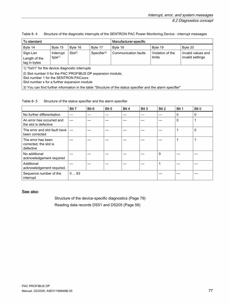
Interrupt, error, and system messages 8.2 Diagnostics concept
PAC PROFIBUS DP Manual, 02/2009, A5E01168846B-05 77
Table 8- 4 Structure of the diagnostic interrupts of the SENTRON PAC Power Monitoring Device - interrupt messages
To standard Manufacturer-specific Byte 14 Byte 15 Byte 16 Byte 17 Byte 18 Byte 19 Byte 20 Sign-Len Length of the tag in bytes
Interrupt type1)
Slot2) Specifier3) Communication faults Violation of the limits
Invalid values and invalid settings
1) "0x01" for the device diagnostic interrupts 2) Slot number 0 for the PAC PROFIBUS DP expansion module; Slot number 1 for the SENTRON PACxxxx Slot number x for a further expansion module 3) You can find further information in the table "Structure of the status specifier and the alarm specifier"
Table 8- 5 Structure of the status specifier and the alarm specifier
Bit 7 Bit 6 Bit 5 Bit 4 Bit 3 Bit 2 Bit 1 Bit 0 No further differentiation — — — — — — 0 0 An error has occurred and the slot is defective
— — — — — — 0 1
The error and slot fault have been corrected
— — — — — — 1 0
The error has been corrected, the slot is defective
— — — — — — 1 1
No additional acknowledgement required
— — — — — 0 — —
Additional acknowledgement required.
— — — — — 1 — —
Sequence number of the interrupt
0 ... 63 — — —
See also Structure of the device-specific diagnostics (Page 79) Reading data records DS51 and DS205 (Page 56)
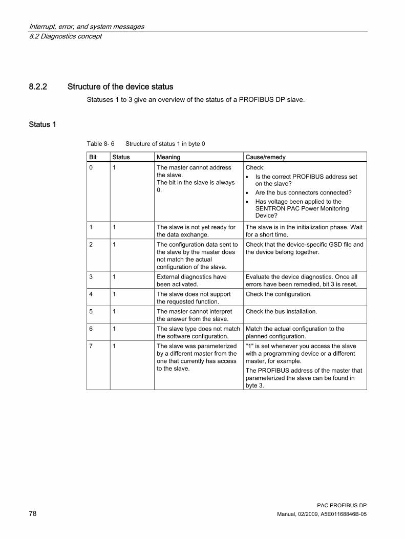
Interrupt, error, and system messages 8.2 Diagnostics concept
PAC PROFIBUS DP 78 Manual, 02/2009, A5E01168846B-05
8.2.2 Structure of the device status Statuses 1 to 3 give an overview of the status of a PROFIBUS DP slave.
Status 1
Table 8- 6 Structure of status 1 in byte 0
Bit Status Meaning Cause/remedy 0 1 The master cannot address
the slave. The bit in the slave is always 0.
Check: • Is the correct PROFIBUS address set
on the slave? • Are the bus connectors connected? • Has voltage been applied to the
SENTRON PAC Power Monitoring Device?
1 1 The slave is not yet ready for the data exchange.
The slave is in the initialization phase. Wait for a short time.
2 1 The configuration data sent to the slave by the master does not match the actual configuration of the slave.
Check that the device-specific GSD file and the device belong together.
3 1 External diagnostics have been activated.
Evaluate the device diagnostics. Once all errors have been remedied, bit 3 is reset.
4 1 The slave does not support the requested function.
Check the configuration.
5 1 The master cannot interpret the answer from the slave.
Check the bus installation.
6 1 The slave type does not match the software configuration.
Match the actual configuration to the planned configuration.
7 1 The slave was parameterized by a different master from the one that currently has access to the slave.
"1" is set whenever you access the slave with a programming device or a different master, for example. The PROFIBUS address of the master that parameterized the slave can be found in byte 3.

Interrupt, error, and system messages 8.2 Diagnostics concept
PAC PROFIBUS DP Manual, 02/2009, A5E01168846B-05 79
Status 2
Table 8- 7 Structure of status 2 in byte 1
Bit Status Meaning Cause/remedy 0 1 Parameters have to be
reassigned to the slave. Check: • The parameter assignment • The configuration • Whether the device-specific GSD file
and the Power Monitoring Device go together.
1 1 There is a diagnostic message.
Clear the fault.
2 1 The bit in the slave is always set to "1".
-
3 1 Response monitoring is enabled for this slave.
-
4 1 The slave has received the "FREEZE" control command.
The "FREEZE" function is not supported. Check the configuration.
5 1 The slave has received the "SYNC" control command.
The "SYNC" function is not supported. Check the configuration.
6 0 This bit is always set to "0". - 7 1 The slave is deactivated. It
has been removed from the current process.
Activate the slave from the master if necessary.
Status 3
Table 8- 8 Structure of status 3 in byte 2
Bit Status Meaning 0 ... 6 0 These bits are always set to "0". 7 1 There are more device diagnostic messages than can be displayed in the
diagnostic message frame.
8.2.3 Structure of the device-specific diagnostics The device diagnostics identify problems that occur while the SENTRON PAC Power Monitoring Device is running.

Interrupt, error, and system messages 8.2 Diagnostics concept
PAC PROFIBUS DP 80 Manual, 02/2009, A5E01168846B-05
Structure
Table 8- 9 Device diagnostics data Yes/No: Structure of the device diagnostics in byte 10
Bit Status Meaning 0 0 Reserved 1 0 Reserved 2 0 Reserved 3 0 Reserved 4 0 Reserved 5 0 Reserved 6 0 Reserved
1 The device diagnostics data is available. 7 0 The device diagnostics data is not available.
Table 8- 10 Communication faults: Structure of the device diagnostics in byte 11 and the interrupt message in byte 18
Bit Status Message 0 1 Internal communication not ready 1 1 Internal communication is faulty 2 0 Reserved 3 1 Data invalid - internal fault (CRC error) 4 0 Reserved 5 1 Data invalid - internal fault (frame error) 6 1 Data invalid - internal fault (timeout) 7 1 Firmware PAC,Module incompatible
Table 8- 11 Violation of the limits: Structure of the device diagnostics in byte 12 and the interrupt message in byte 19
Bit Status Message 0 1 Voltage out of range 1 1 Current out of range 2 1 Maximum pulse rate exceeded 3 1 Limit violations 4 0 Reserved 5 0 Reserved 6 0 Reserved 7 0 Reserved

Interrupt, error, and system messages 8.2 Diagnostics concept
PAC PROFIBUS DP Manual, 02/2009, A5E01168846B-05 81
Table 8- 12 Invalid values and invalid settings: Structure of the device diagnostics in byte 13 and the interrupt message in byte 20
Bit Status Message 0 1 Output not remote operated 1 1 Invalid val. for Op.Hrs/Univ.Cnt1) 2 1 Invalid value for energy counter 3 1 Invalid settings for PMD1) 4 1 Invalid settings for limits1) 5 0 Reserved (invalid data for DSxx) 6 0 Reserved (invalid data for DSxx) 7 0 Reserved (invalid data for DSxx)
1) On SENTRON PAC3200 only
See also Device-specific diagnostic messages (Page 81) Diagnostic interrupt (Page 76) Limits (Page 58)
8.2.4 Device-specific diagnostic messages
SENTRON PAC diagnostic messages You can call the device diagnostic interrupts online, in STEP 7 in the SIMATIC Manager, for example.
Table 8- 13 Implemented device diagnostic interrupts
Message Meaning Remedy Internal communication not ready Communication between the expansion
module and the SENTRON PAC Power Monitoring Device is not ready, e.g., during the initialization phase.
—
Firmware PAC,Module incompatible The firmware of the SENTRON PAC Power Monitoring Device and of the PAC PROFIBUS DP expansion module are not compatible.
Update the firmware.
Internal communication fault A permanent communication error has occurred between the SENTRON PAC Power Monitoring Device and the expansion module.
Replace the expansion module.
Data invalid The actual data for the expansion module are not up-to-date.
The data are updated automatically. If the message does not disappear, replace the expansion module.

Interrupt, error, and system messages 8.2 Diagnostics concept
PAC PROFIBUS DP 82 Manual, 02/2009, A5E01168846B-05
Message Meaning Remedy Voltage out of range The measured voltage is at least 20 %
over the normal value. Check: • The voltage converter ratio • The setting of the rated voltage If these settings are correct and the error persists, there is a safety problem. Switch the device off.
Current out of range The measured current is at least 20 % over the normal value.
There is a measuring error. If the error persists, check the following: • The dimensioning of the current
transformer. • The settings for the current
transformer on the SENTRON PAC.
Maximum pulse rate exceeded The maximum frequency of the pulse output does not represent the measured energy.
Check whether: • The number of parameterized
pulses is too low. • The parameterized pulse is too
long. If necessary, adjust the relevant settings.
Limit violations Since the last readout, at least one of the set limit violations has changed. • Limit value exceeded • Limit value no longer exceeded
—
Output not remote operated Data record DS68 has been sent to change the status of the digital output, but the parameter "Digital output, action" is not at "remote operated"
Set "remote output" in the "Action" field of the "Digital Output" (24.0) screen form on the SENTRON PAC.
Invalid val. for Op.Hrs/Univ.Cnt.1) Data record DS98 contains an invalid value for the working hours counter or the universal counter.
Check: • The settings on the SENTRON PAC• The values
Invalid value for energy counter Data record DS205 contains an invalid value for the energy counter.
Check: • The settings on the SENTRON PAC• The values
Invalid settings for PMD1) Data record DS131 contains invalid settings for the Power Monitoring Device.
Check: • The settings on the SENTRON PAC• The values
Invalid settings for limits1) Data record DS132 contains an invalid value for the limit violations.
Check: • The settings on the SENTRON PAC• The values
Reserved (invalid data for DSxx) Data record DSxx contains: • An invalid offset • Incorrect number of registers
Check: • The offset • The number of registers
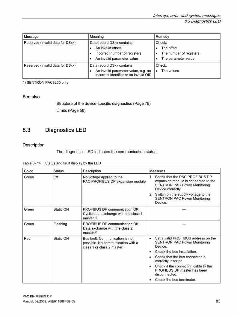
Interrupt, error, and system messages 8.3 Diagnostics LED
PAC PROFIBUS DP Manual, 02/2009, A5E01168846B-05 83
Message Meaning Remedy Reserved (invalid data for DSxx) Data record DSxx contains:
• An invalid offset • Incorrect number of registers • An invalid parameter value
Check: • The offset • The number of registers • The parameter value
Reserved (invalid data for DSxx) Data record DSxx contains: • An invalid parameter value, e.g. an
incorrect identifier or an invalid OID
Check: • The values.
1) SENTRON PAC3200 only
See also Structure of the device-specific diagnostics (Page 79) Limits (Page 58)
8.3 Diagnostics LED
Description The diagnostics LED indicates the communication status.
Table 8- 14 Status and fault display by the LED
Color Status Description Measures Green Off No voltage applied to the
PAC PROFIBUS DP expansion module 1. Check that the PAC PROFIBUS DP
expansion module is connected to the SENTRON PAC Power Monitoring Device correctly.
2. Switch on the supply voltage to the SENTRON PAC Power Monitoring Device.
Green Static ON PROFIBUS DP communication OK. Cyclic data exchange with the class 1 master.1)
—
Green Flashing PROFIBUS DP communication OK. Data exchange with the class 2 master.2)
—
Red Static ON Bus fault. Communication is not possible. No communication with a class 1 or class 2 master.
• Set a valid PROFIBUS address on the SENTRON PAC Power Monitoring Device.
• Check the bus installation. • Check that the bus connector is
correctly inserted. • Check if the connecting cable to the
PROFIBUS DP master has been disconnected.
• Check the bus terminator.

Interrupt, error, and system messages 8.3 Diagnostics LED
PAC PROFIBUS DP 84 Manual, 02/2009, A5E01168846B-05
Color Status Description Measures Red Flashing Parameter assignment error:
• The slave has not been parameterized or has been wrongly parameterized.
• An incorrect station address has been assigned.
• An incorrect GSD file has been used.
The red LED does not go off until a master is connected to the network
• Check the communication and the parameter assignment.
• Check the PROFIBUS address. • Check whether the GSD file matches
the firmware version and the hardware version of the expansion module.
Communication between the PAC PROFIBUS DP expansion module and the SENTRON PAC Power Monitoring Device has been interrupted.
Check the operating capability of the SENTRON PAC Power Monitoring Device.
The orange LED lights up briefly, e.g. during the initialization phase • The LED turns green when
communication has been restored.
The usual diagnostics options on the master, e.g., error OB8x, are available for use.
Orange Static ON
The LED lights up orange for a longer time: An internal fault has occurred.
• Restart the device. • Replace the expansion module and/or
the device.
Orange Flashing No parameters for the expansion module are displayed on the SENTRON PAC. Hardware fault on the expansion module or the SENTRON PAC Power Monitoring Device, e.g.: • 12 V too weak or not present • SRAM fault • Flash fault • EEPROM fault
Replace the PAC PROFIBUS DP expansion module and/or the SENTRON PAC Power Monitoring Device.
Green, red, orange
Flashing A firmware update is active. Allow the firmware update to run to the end! The firmware update lasts approximately 8 to 13 minutes. Do not interrupt the operation!
1) A parallel connection to a class 2 master has no effect on the green status of the LED. 2) This is only the case if there is no connection to the class 1 master.
PAC PROFIBUS DP Manual, 02/2009, A5E01168846B-05 85
Troubleshooting/FAQs 99.1 Power failure during firmware update
Effect and measures
CAUTION Power failure during firmware update disables the functionality of the expansion module The firmware update lasts approximately 8 to 13 minutes. To update the firmware of the expansion module, connect the SENTRON PAC and the PAC PROFIBUS DP expansion module to a fail-safe power supply. If the power fails despite this security measure, try to start the firmware update of the PAC PROFIBUS DP expansion module again in SENTRON powerconfig.
See also Firmware updates (Page 74) Latest information and correction sheet (Page 10)

Troubleshooting/FAQs 9.1 Power failure during firmware update
PAC PROFIBUS DP 86 Manual, 02/2009, A5E01168846B-05
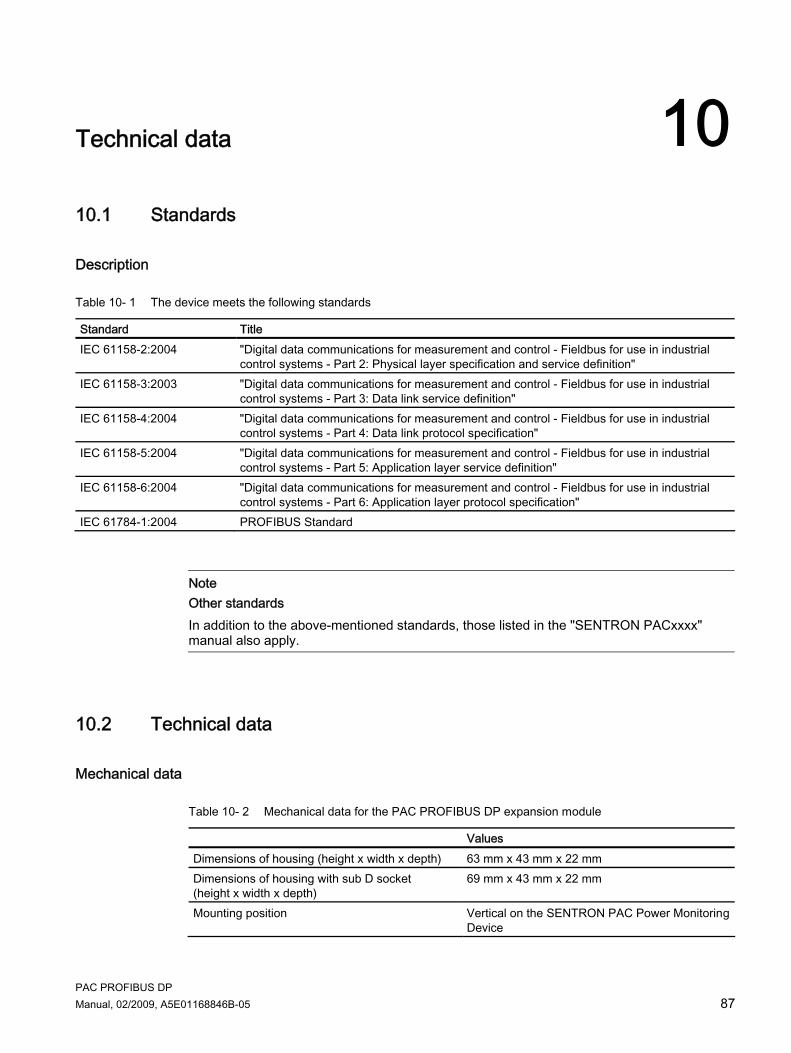
PAC PROFIBUS DP Manual, 02/2009, A5E01168846B-05 87
Technical data 1010.1 Standards
Description
Table 10- 1 The device meets the following standards
Standard Title IEC 61158-2:2004 "Digital data communications for measurement and control - Fieldbus for use in industrial
control systems - Part 2: Physical layer specification and service definition" IEC 61158-3:2003 "Digital data communications for measurement and control - Fieldbus for use in industrial
control systems - Part 3: Data link service definition" IEC 61158-4:2004 "Digital data communications for measurement and control - Fieldbus for use in industrial
control systems - Part 4: Data link protocol specification" IEC 61158-5:2004 "Digital data communications for measurement and control - Fieldbus for use in industrial
control systems - Part 5: Application layer service definition" IEC 61158-6:2004 "Digital data communications for measurement and control - Fieldbus for use in industrial
control systems - Part 6: Application layer protocol specification" IEC 61784-1:2004 PROFIBUS Standard
Note Other standards In addition to the above-mentioned standards, those listed in the "SENTRON PACxxxx" manual also apply.
10.2 Technical data
Mechanical data
Table 10- 2 Mechanical data for the PAC PROFIBUS DP expansion module
Values Dimensions of housing (height x width x depth) 63 mm x 43 mm x 22 mm Dimensions of housing with sub D socket (height x width x depth)
69 mm x 43 mm x 22 mm
Mounting position Vertical on the SENTRON PAC Power Monitoring Device

Technical data 10.2 Technical data
PAC PROFIBUS DP 88 Manual, 02/2009, A5E01168846B-05
Values Housing design VDT 3400 structure 36 Tolerances According to DIN 16901:1982-11 Weight 45 g Connector to SENTRON PAC Power Monitoring Device
14-pin connector
Length of cable Dependent on baud rate. More information about cable lengths can be found in section 21.1 of standard IEC 61158-2:2004 and IEC 61158-2:2003
Power supply Power supplied by SENTRON PACxxxx Cooling Passive air cooling in form of ventilation slots Flammability class V-0
Electrical data
Table 10- 3 Electrical data for the PAC PROFIBUS DP expansion module
Values ANSI TIA/EIA-485-A1) Protective circuit for PROFIBUS interface, galvanically isolated from the device
5 V ± 5 %
Maximum current (of 5 V on PROFIBUS DP connector)
10 mA, maximum
Electrical isolation between the SENTRON PAC Power Monitoring Device and the PROFIBUS DP interface
500 V
Galvanic isolation In expansion module Insulating voltage Max. 500 V 1) Formerly RS 485
Ambient and environmental conditions
Table 10- 4 Ambient and environmental conditions
Ambient and environmental conditions Values Degree of protection in accordance with DIN EN 60529 IP20 Permissible degree of pollution 2 in accordance with
IEC 61010-1:2001 Recycling symbol > PC / ABC <
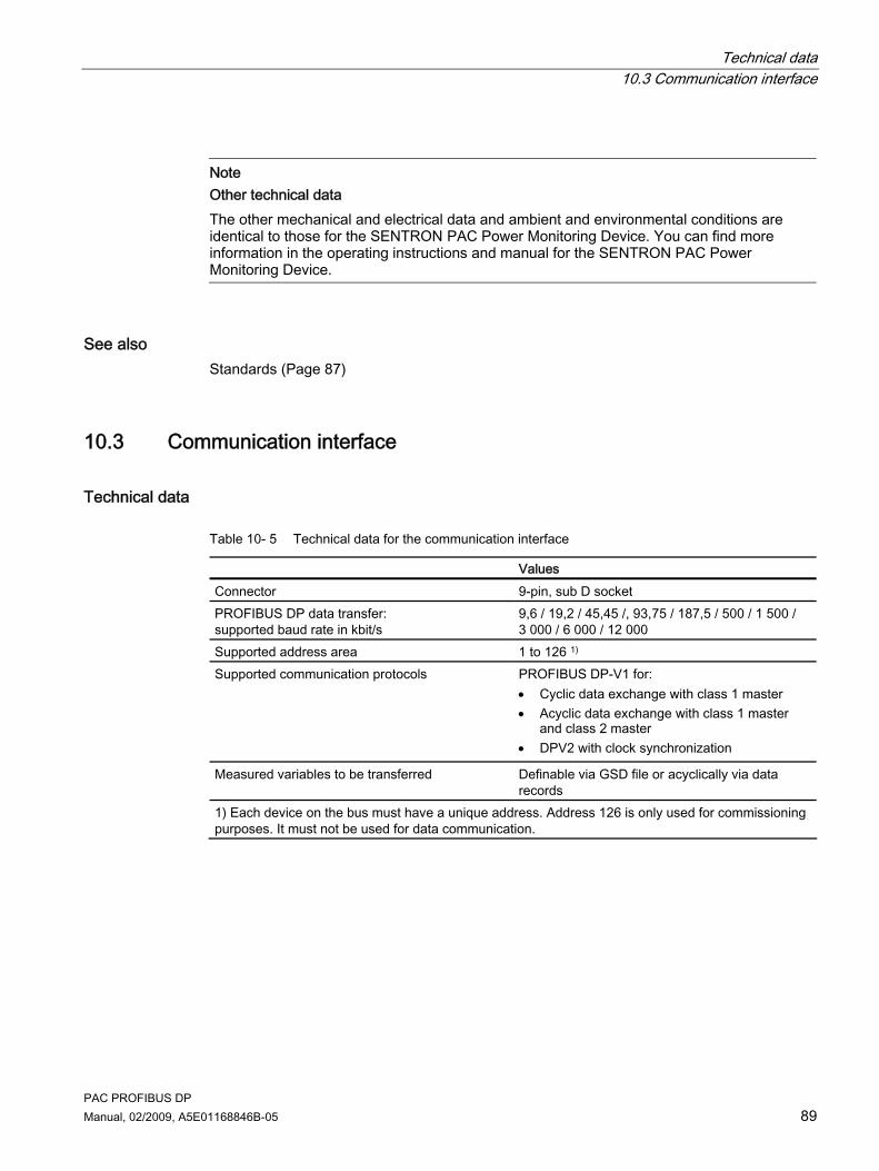
Technical data 10.3 Communication interface
PAC PROFIBUS DP Manual, 02/2009, A5E01168846B-05 89
Note Other technical data The other mechanical and electrical data and ambient and environmental conditions are identical to those for the SENTRON PAC Power Monitoring Device. You can find more information in the operating instructions and manual for the SENTRON PAC Power Monitoring Device.
See also Standards (Page 87)
10.3 Communication interface
Technical data
Table 10- 5 Technical data for the communication interface
Values Connector 9-pin, sub D socket PROFIBUS DP data transfer: supported baud rate in kbit/s
9,6 / 19,2 / 45,45 /, 93,75 / 187,5 / 500 / 1 500 / 3 000 / 6 000 / 12 000
Supported address area 1 to 126 1) Supported communication protocols PROFIBUS DP-V1 for:
• Cyclic data exchange with class 1 master • Acyclic data exchange with class 1 master
and class 2 master • DPV2 with clock synchronization
Measured variables to be transferred Definable via GSD file or acyclically via data records
1) Each device on the bus must have a unique address. Address 126 is only used for commissioning purposes. It must not be used for data communication.
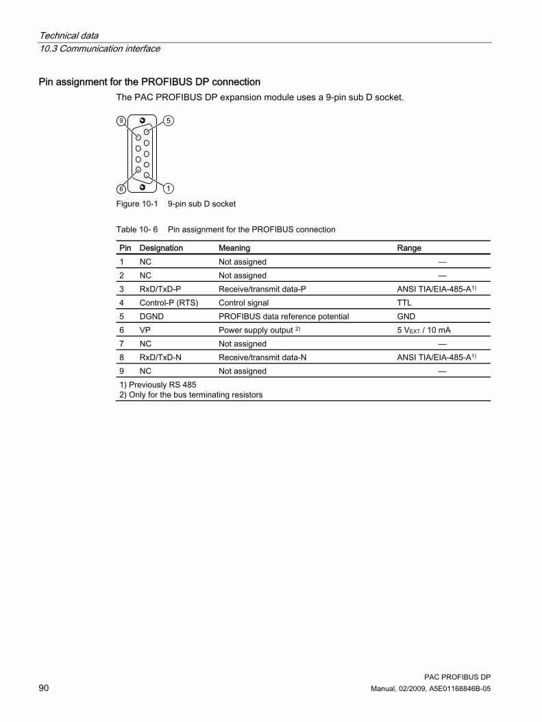
Technical data 10.3 Communication interface
PAC PROFIBUS DP 90 Manual, 02/2009, A5E01168846B-05
Pin assignment for the PROFIBUS DP connection The PAC PROFIBUS DP expansion module uses a 9-pin sub D socket.
Figure 10-1 9-pin sub D socket
Table 10- 6 Pin assignment for the PROFIBUS connection
Pin Designation Meaning Range 1 NC Not assigned — 2 NC Not assigned — 3 RxD/TxD-P Receive/transmit data-P ANSI TIA/EIA-485-A1) 4 Control-P (RTS) Control signal TTL 5 DGND PROFIBUS data reference potential GND 6 VP Power supply output 2) 5 VEXT / 10 mA 7 NC Not assigned — 8 RxD/TxD-N Receive/transmit data-N ANSI TIA/EIA-485-A1) 9 NC Not assigned — 1) Previously RS 485 2) Only for the bus terminating resistors

Technical data 10.4 Labeling
PAC PROFIBUS DP Manual, 02/2009, A5E01168846B-05 91
10.4 Labeling
Description The graphic below shows the positioning of the label on the housing of the PAC PROFIBUS DP expansion module.
(1) Nameplate
Figure 10-2 The PAC PROFIBUS DP expansion module with label

Technical data 10.4 Labeling
PAC PROFIBUS DP 92 Manual, 02/2009, A5E01168846B-05

PAC PROFIBUS DP Manual, 02/2009, A5E01168846B-05 93
Dimension sheets 1111.1 Dimension sheets
PAC PROFIBUS DP expansion module
Figure 11-1 Side view and front view with sub D socket
Figure 11-2 Bottom view and top view with sub D socket connector and the dimensions of the pin
contact between the PAC PROFIBUS DP expansion module and the SENTRON PAC
All dimensions are specified in mm.

Dimension sheets 11.1 Dimension sheets
PAC PROFIBUS DP 94 Manual, 02/2009, A5E01168846B-05

PAC PROFIBUS DP Manual, 02/2009, A5E01168846B-05 95
Appendix A
Correction sheet Have you noticed any errors while reading this manual? If so, please use this form to tell us about them. We welcome comments and suggestions for improvement.

Appendix
PAC PROFIBUS DP 96 Manual, 02/2009, A5E01168846B-05
Fax response From (please complete): To SIEMENS AG I IA CD MM 3 92220 Amberg / Germany
Name Company/Department Address
_________________________________________________________________________________ Fax: +49 (0)9621-80-3337 Manual title:
Table A- 1 Errors, comments, and suggestions for improvements

PAC PROFIBUS DP Manual, 02/2009, A5E01168846B-05 97
ESD directives BB.1 Electrostatic sensitive devices (ESD)
ESD components are destroyed by voltage and energy far below the limits of human perception. Voltages of this kind occur as soon as a device or an assembly is touched by a person who is not electrostatically discharged. ESD components which have been subject to such voltage are usually not recognized immediately as being defective, because the malfunction does not occur until after a longer period of operation.
ESD guidelines
CAUTION Electrostatic sensitive devices Electronic modules contain components that can be destroyed by electrostatic discharge. These modules can be easily destroyed or damaged by improper handling. • You must discharge your body electrostatically immediately before touching an
electronic component. To do this, touch a conductive, grounded object, e.g., a bare metal part of a switch cabinet or the water pipe.
• Always hold the component by the plastic enclosure. • Electronic modules should not be brought into contact with electrically insulating
materials such as plastic film, plastic parts, insulating table supports or clothing made of synthetic fibers.
• Always place electrostatic sensitive devices on conductive bases. • Always store and transport electronic modules or components in ESD-safe conductive
packaging, e.g. metallized plastic or metal containers. Leave the component in its packaging until installation.
CAUTION Storage and transport If you have to store or transport the component in non-conductive packaging, you must first pack the component in ESD-safe, conductive material, e.g., conductive foam rubber, ESD bag.
The diagrams below illustrate the required ESD protective measures for electrostatic sensitive devices.

ESD directives B.1 Electrostatic sensitive devices (ESD)
PAC PROFIBUS DP 98 Manual, 02/2009, A5E01168846B-05
(1) ESD seat (2) ESD standing position (3) ESD seat and ESD standing position Protective measures a Conductive floor b ESD table c ESD footwear d ESD smock e ESD bracelet f Cubicle ground connection

PAC PROFIBUS DP Manual, 02/2009, A5E01168846B-05 99
List of abbreviations CC.1 Abbreviations
Overview
Table C- 1 Meaning of abbreviations
Abbreviation Meaning ANSI American National Standards Institute CAN Controller Area Network CE Communautés Européennes CEI Commission Electrotechnique Internationale CISPR Comité international spécial des perturbations radioélectriques CRC Cyclic Redundancy Check CSA Canadian Standards Association DIN Deutsches Institut für Normierung e. V. DP Distributed I/Os DR Data record ESD Electrostatic sensitive devices EIA Electronic Industries Alliance EMC Electromagnetic compatibility EN European Standard EU European Union FCC Federal Communications Commission GSD Device master data HT High Tariff HW Config "Hardware configuration" module in the SIMATIC Manager I&M Information and Maintenance ID Identification number IEC International Electrotechnical Commission IEEE Institute of Electrical and Electronics Engineers IP International Protection ISM Industrial, Scientific and Medical ISO International Organization for Standardization LED Light Emitting Diode LSB Least Significant Bit LT Low Tariff MSB Most Significant Bit MS0 Cyclic Master Slave Communication (master class 1)

List of abbreviations C.1 Abbreviations
PAC PROFIBUS DP 100 Manual, 02/2009, A5E01168846B-05
Abbreviation Meaning MS1 Acyclic Master Slave Communication (master class 1) MS2 Acyclic Master Slave Communication (master class 2) NAFTA North American Free Trade Agreement NEMA National Electrical Manufacturers Association PAC Power Analysis & Control PMD Power Monitoring Device PI PROFIBUS user organization RALRM Read alarm RDREC Read record RET_VAL Return value: "Return value" RMS Root Mean Square RMS RS Formerly: Radio Selector; now usually: Recommended Standard SFB System function block SFC System function TIA Totally Integrated Automation THD Total Harmonic Distortion Total Harmonic Distortion THD-R Relative THD UL Underwriters Laboratories Inc. VDE Association of Electrical Engineering, Electronics and Information Technology
(Germany) RLO Result of logic operation WRREC Write record

PAC PROFIBUS DP Manual, 02/2009, A5E01168846B-05 101
Glossary
Baud rate The baud rate is the rate of data transmission. It indicates the number of bits transferred in one second. All nodes on a PROFIBUS subnet must support the selected baud rate.
Bus Shared transmission path over which all devices on the communication bus are connected. It has two defined ends. In the case of PROFIBUS, the bus is a twisted pair or optical fiber cable.
Bus system All nodes physically connected to a bus cable form a bus system.
Class 1 DP master The class 1 DP master handles user data traffic with the DP slaves assigned to it.
Class 2 DP master The DP master provides services such as reading the input data, output data, diagnostics, and control bytes.
Cycle time The cycle time of a PROFIBUS segment is made up of the number of nodes. It is set, for example, in STEP 7 in the HW Config.
Cyclic execution The DP master accesses the DP slaves regularly. In doing so, the DP master reads the input data of the slaves and forwards output data to the slaves.
Diagnostics The detection, localization, visualization and further evaluation of errors, disturbances and messages. Diagnostics offers monitoring functions that automatically run while the system is in operation. This reduces startup times and standstill times. Plant availability increases.
Glossary
PAC PROFIBUS DP 102 Manual, 02/2009, A5E01168846B-05
Equipotential bonding Electrical connection (equipotential bonding conductor) which brings the bodies of electronic equipment and foreign conductive bodies to an equal or approximately equal potential. This prevents disruptive or dangerous voltages between these bodies.
Master When a master is in possession of the token, it can send data to other nodes and request data from other nodes.
Nodes Device which can send, receive or amplify data on the bus, e.g., PROFIBUS DP master, PROFIBUS DP slave.
PROFIBUS PROCESS FIELDBUS, a European process and fieldbus standard defined in the PROFIBUS standard EN 50170, Volume 2 PROFIBUS. This standard specifies the operational, electrical and mechanical properties of a bit-serial field bus system. PROFIBUS is a bus system that connects PROFIBUS-compatible automation systems and field devices together at the cell level and field level.
PROFIBUS address Every device on the communication bus receives a unique PROFIBUS address. The device on the communication bus is identified on PROFIBUS with this address. The factory address setting for the PAC PROFIBUS DP expansion module is address 126. Addresses 1 to 126 are permissible.
Slave A slave can only exchange data after being requested to by the master.

PAC PROFIBUS DP Manual, 02/2009, A5E01168846B-05 103
Index
" "DIAG" field, 70 "RALRM" function block, 53 "RDREC" function block, 53 "WRREC" function block, 53
A Active energy export, 58 Active energy import, 58 Active energy import tariff 1, 26 Acyclic data traffic, 31, 52 Acyclic data transfer, 14 Address, 61, 62
Change, 63 Address area
Supported, 89 Valid, 71
Ambient conditions, 88 ANSI TIA/EIA 485 A protective circuit, 88 Apparent energy, 58 Apply supply voltage, 17 Area of application, 13 Assembly, 17, 18 Average power values over a demand period, 32, 49
B Basic type, 24 Basic type 1, 24, 25, 26, 30, 32, 34 Basic type 2, 24, 26, 32, 34
Length of message, 26 Basic type 3, 24, 26, 30 Baud rate, 14, 24, 61, 71, 89 Block libraries for SIMATIC, 23, 31 Bottom view, 93 Bus connector, 78 Bus fault, 83 Bus installation, 78 Bus traffic, 14
C CALL mechanism, 56
Class 1 master, 71, 83 Class 2 master, 31, 71, 83 Cleaning, 11, 73 Clear memory contents, 30 Clock synchronization, 14 Command information, 39 Commands, 30, 32 Commissioning, 62 Communication, 81, 84
Status, 70 Communication error
Permanent, 81 Communication faults, 80 Communication interface, 89 Communication parameters, 61 Communication protocols
Supported, 89 Communication status, 83 Component diagnostics, 29 Condensation, 18 Conductive floor, 98 Configuration message frame
Incorrect, 71 Configure, 17 Connector, 89
Defective, 73 Connector to SENTRON PAC Power Monitoring Device, 88 Control bytes, 25, 26, 30 Cooling, 88 Correction sheet, 95 Cross-tip screwdriver, 18 Cubicle ground connection, 98 Current, 25 Current measured values, 32, 40 Current out of range, 82 Current terminals, 20 Current values, 32, 36, 46 Cyclic data exchange, 83 Cyclic data traffic, 24, 28 Cyclic data transfer, 14
D Data exchange
Cyclic, 83 Data invalid, 81 Data traffic

Index
PAC PROFIBUS DP 104 Manual, 02/2009, A5E01168846B-05
Acyclic, 31 Cyclic, 24, 28
Data volume, 24 Default settings, 61 Degree of protection, 88 Detergents
Damage, 73 Device diagnostic interrupts, 81 Device diagnostics, 29, 30, 76, 78, 79
Structure, 80 Device diagnostics data, 80 Device status, 29 Diagnostic information, 29, 39, 76 Diagnostic interrupts, 59, 76 Diagnostic message frame, 79 Diagnostic messages, 81 Diagnostics address, 50 Diagnostics LED, 83 Digital data communications for measurement and control, 87 Digital inputs status, 35, 59 Digital outputs status, 35, 59 Dimensions of housing, 87 Discharge, 20, 73, 97 Disposal, 74 Double Float format, 58 DPV1 data record, 31 DPV1-enabled master, 31
E Edge transition, 30 Electrical data, 88 Electrical isolation, 88 Electrostatic sensitive devices, 97 Endangering of operation, 19 Energy counter, 48 Energy counters, 32, 58
Reset, 30 Energy values, 23 Enhanced diagnostics, 76 Environmental conditions, 88 Error Code 1, 55 Error message frame, 54 ESD bracelet, 98 ESD footwear, 98 ESD guidelines, 97 ESD Guidelines, 18 ESD protective measures, 97 ESD seat, 98 ESD smock, 98 ESD standing position, 98
ESD table, 98
F Factory settings, 61 Fail-safe power supply, 85 Fault display, 83 Features, 14 Firmware incompatible, 81 Firmware update, 84, 85
Duration, 85 Firmware updates, 74 Firmware version of the expansion module, 70 Flammability class, 88 Float format, 58 Front view, 93 Functions with limited support, 15
G Galvanic isolation, 88 GSD file, 14, 17, 78, 79
Language, 64 GSDF file, 24, 63 Guide pin, 20
H Hardware fault, 84 High tariff, 30 Housing design, 88 Humidity, 11 HW Config, 65
I I&M data, 50 I&M data records, 32, 50 I&M device identification, 32 IM0 data, 50 IM1 data, 51 IM2 data, 51 IM3 data, 51 IM4 data, 52 Index, 52 Index 255, 50 Initialization phase, 78 Input data, 25, 26, 27 Input signals, 35 Installation location, 17

Index
PAC PROFIBUS DP Manual, 02/2009, A5E01168846B-05 105
Insulating voltage maximum, 88
Intended use, 13 Interrupt message, 77, 81 Interrupt type, 77 Invalid settings, 81, 82 Invalid values, 81
L Labeling, 91 Language, 61 LED, 15, 83 Length of cable, 88 Level sensitive, 30 Limit value settings, 32 Limit values, 59 Limit violations, 82 Line frequency, 32 Line frequency values, 38 Loss of warranty, 73 Low tariff, 30
M Manufacturer's ID, 76 Master, 76, 78
Class 1, 54, 71, 83 Class 2, 31, 71, 83
Master-slave principle, 14 Maximum pulse rate exceeded, 82 Maximum values
Reset, 30 Maximum/minimum values, 23 Measured variables, 23, 24
free choice, 28 Mechanical data, 87 Message frame, 24 Message frame formats, 54 Minimum values
Reset, 30 Modular system design, 52 Moisture, 11 Mounting position, 87
N Nameplate, 91 Number of nodes, 24
O Order number, 70 Orientation aids, 9 Output data, 25 Output not remote operated, 82 Output signals, 35
P Packaging, 18 Parameter assignment, 84 Parameter assignment error, 84 Parameterize, 17 Parameters for setting the limit values, 44 Perform checks, 18 Permissible degree of pollution, 88 Pin, 19, 73 PIN assignment, 90 Power failure, 85 Power measured values, 32, 40 Power supply, 88
Fail-safe, 85 Power values, 32, 37, 48 Process interrupts
Structure, 75 PROFIBUS adaptor plug, 21 PROFIBUS address, 17, 71, 78, 83 PROFIBUS address of the master, 76 PROFIBUS connection, 90 PROFIBUS DP master, 63 PROFIBUS DP Master, 14, 17 PROFIBUS DP slave, 14, 63 PROFIBUS functions, 16 PROFIBUS ID number, 63 PROFIBUS network, 17 Pulse rate, 29
Q Quantity structure, 24
R Reactive energy export, 58 Reactive energy import, 58 Recycling, 74 Recycling symbol, 88 Repair, 73 Required basic knowledge, 9 Response monitoring, 14, 79

Index
PAC PROFIBUS DP 106 Manual, 02/2009, A5E01168846B-05
RS 485 protective circuit, 88
S S7-V1 system diagnostics, 33 Safe isolation from supply, 20 SENTRON PAC events, 75 Serial number, 70 Setting parameters, 42 SFB 52 "RDREC", 53 SFB 53 "WRREC", 53 SFB 54 "RALRM", 53 Side view, 93 SIMATIC environment, 61 SIMATIC Manager, 65 Slave, 76, 78, 84 Slave diagnostics in accordance with standard, 76 Slot, 76 Slot number, 52 Slot number 0, 50 Slot number 1, 50 Specifier, 76, 77 station address
Incorrect, 71 Status 1, 78 Status 2, 79 Status 3, 79 Status and diagnostics, 32 Status display, 83 Status information, 23, 25, 28, 29, 39 Status of the input signals, 32 Status of the output signals, 32 Status type, 76 STEP 7, 81 Storage, 97 Structure, 15 Structure of the device diagnostics, 80 Structure of the process interrupts, 75 Sub D connector, 19, 20 Sub D socket, 15, 20, 21, 87, 89, 93 Support
Technical, 73 Switch outputs, 30 Switching tariff, 30 System function blocks, 53 System function blocks (SFB53/54), 31 System status, 29
T Technical data, 89
Technical support, 73 Temperature compensation, 18 THD values, 32, 38 Tightening torque, 20 Tolerances, 88 Tools, 18 Top view, 93 Total active power, 25 Total power factor, 26 Transport, 97
U Universal counter, 32, 42 Unpacking, 18 Update firmware, 81
V Valid address area, 71 Ventilation slots, 15, 19, 21, 88 Violation of the limits, 80 Voltage measured values, 32, 40 Voltage out of range, 82 Voltage ph-ph, 26 Voltage terminals, 20 Voltage values, 32, 36, 47
W Weight, 88 Wetness, 11 Working hours counter, 32, 42
Y Y link, 15